Isuzu N-Series. Service manual - part 1297


  Index      Isuzu     Isuzu N-Series - service and repair manual


Search            


Content   ..  1295  1296  1297  1298   ..


Isuzu N-Series. Service manual - part 1297


Adjustment

1. Adjustment of front hub bearing.
To adjust front hub bearing in axial
retightening force, tighten fastening
nut with wrench, and loosen knuckle
nut for about 120毅 . Rotate the hub
clockwise and anti-clockwise, make
sure that roller against the tapered
face of bearing outer race properly,
then tighten nut to the position where
the rabbet aims the split pin hole.
Check the hub if it can rotate freely
and don't swing a lot. Now, distort
the split pin and fix it.
2. Adjustment of clearance between
knuckle and front axle. The clearance
is adjusted via adjusting shim, it
should less than 0.1mm, and the
number of shim should not more than

2 pieces.
3. Adjustment of toeing-in. The toe鄄
ing-in can be adjusted via adjusting
tie rod. Park the vehicle on a flat
ground, jack up its header and orient
front wheels just as vehicle run for鄄
ward. Loosen locking nuts of tie rod,
rotate the tie rod utile the toeing-in fit
the sp ecified size. Then tighten the
locking nuts with torque of 107 ~
127N窑m.

Steering system

General structure

The steering system of this series of
truck is non-power steering system.
The s teering system composed of
steering control mechanism, linkage
mechanism and steering gear. See
the figure on the right.

Operation inspection for ste -
ering mechanism

1. Put front wheels on a swivel table.
2. Rotate steering wheel clockwise
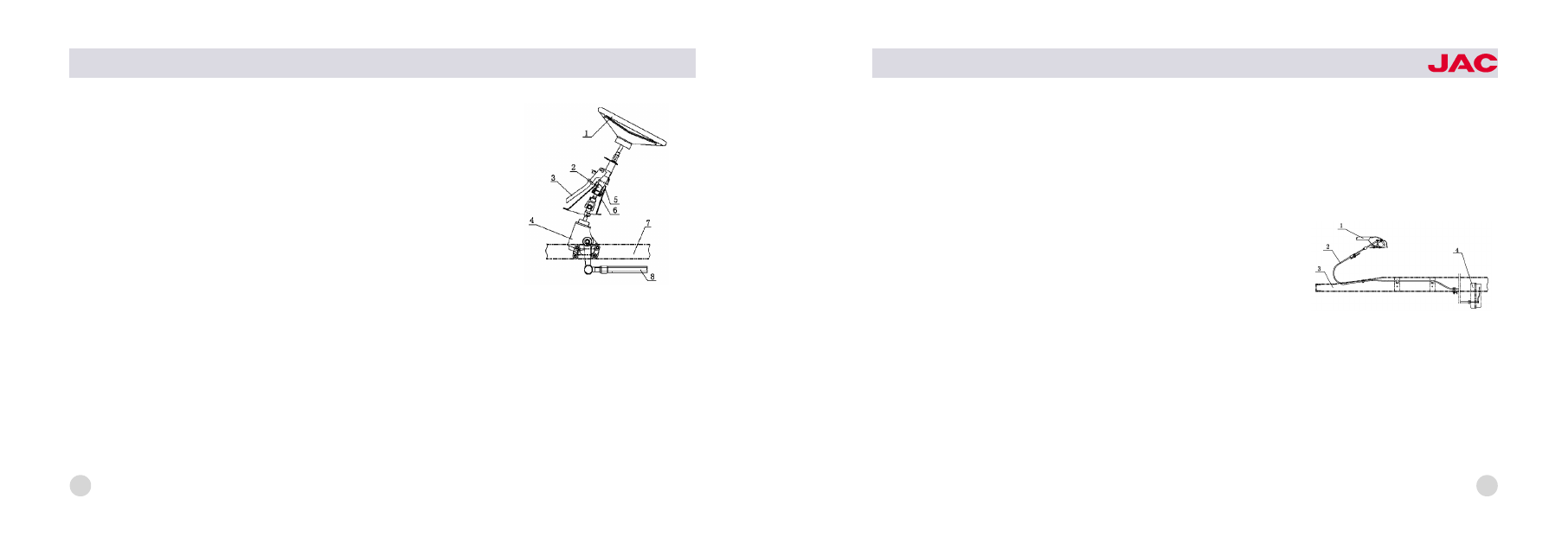
1尧steering wheel;

2尧steering shaft and

universal joint assembly
3尧adjustable bracket; 4尧steering gear
5尧dust cover;

6尧column cover

7尧longitudinal member; 8尧drag link

steering system

40

HFC1020

series trucks

and anti -clockwise to its limit posi鄄
tion, to detect if it is fluent.
3. Let engine run in idle speed and
check steering wheel for free play.
The limit value of this free play is 10~
15mm. Rotate the adjusting screw
clockwise to decrease the free play,
while rotate anti -clockwise to in鄄
crease.
4. When engine run in idle speed,
the torque of steering wheel should
be around 19.5N.

Use & Maintenance

1. Don't steer when parking, since it
will shorten useful life of parts.
2. Check free play of steering wheel
every 1000km (always let engine run
in idle speed when do this opera鄄
tion). The limit value of this free play

is 10~15mm. Rotate adjusting screw
if the free play beyond this limit. Ro鄄
tate it clockwise to decrease the free
play, while rotate anti -clockwise to
increase.
3. Check steering gear box for oil
level every 3000km. Oil level should
not be 20mm below the lower edge
of filler hole. Disassemble and clean
steering wheel two times every year
at beginning of spring and autumn,
replace oil and adjust seasonally.
4. The free play of steering play
should not be too small, since a
small free play will make it hard to
return and bring a worse stability in
high speed.
5. Fill the steering gear box with hy鄄
perbolic -gear oil, don't mix it add

other oil.

Brake system

The brake system of this series truck
is composed of parking brake sys鄄
tem and running brake system.

Parking brake system

General Structure
The parking brake system includes
control lever, pull wire, and parking
brake, as the last figure. Parking

1尧control lever 2尧pull wire
3尧frame

4尧parking brake

parking brake system
control mechanism

41

brake, which is mounted next to
transmission, is center drum brake. It
can act on drive shaft when vehicle
is parking. Also it can operate with
running brake together in emer鄄
gence. The control handle is con鄄
nected with brake by cable whose
core is a steel wire of 椎3.5mm. The
parking brake is composed of back
plate, brake shoe set with pad, ad鄄
justing bolt set, and return spring.

Adjustment

Normally, the clearance between
parking brake drum and brake pad
is 0.65mm, and it is homogeneous in
upper and lower parts. The pad
should be replaced often. Following
these steps.
1. Jacking up rear axle until one

wheel deviate from ground.
2. Release the brake handle com鄄
pletely, shift gears to neutral position.

3. Rotate brake drum until the hole
gets its lowest position. Insert a
screwdriver through this hole to stir
the adjusting nut upward until brake

drum braked completely Then return
the adjusting nut for 2~6 teeth. See
the right figure.
Adjusted according to these steps,
vehicle can parking on road with
20% gradient and can not start even
transmission shifted to 2nd.
Use & Check
Check and adjust the clearance be鄄
tween brake pad and drum.

adjustment of the clearance between

brake pad and drum

42

HFC1020

series trucks

Running brake system

General Structure
The running brake system is hdraulic.

It is composed of vacuum booster,
vacuum cylinder, master cylinder,
control mechanism, brake tube, front
brake and rear brake. It is sensitive
and reliable, and it is simple to ma鄄
nipulate. See the last figure.
If you feel braking power is not suffi鄄
cient when brake pedal is depressed
completely and oil level is normal,
there may be air in brake system.
Bleed system in the following se鄄
quence. Firstly, bleed RR brake;
secondly, bleed LR brake; thirdly,
bleed RF brake; then bleed LF
brake. Following these steps:
1. Clean air -drain screw of main
cylinder and wheel cylinder;
2. Remove oil -drain plug of main
cylinder or reservoir and fill it with

brake fluid until fluid level reach the
edge.
3. Depress the brake pedal several
times before hold it depressed and
release the air-drain screw to bleed.
Repeat doing this until air in tube be
bled completely. Keep a little oil left,
or air can reenter the system.
4. Fill reservoir with brake fluid.

1尧control mechanism
2尧vacuum booster
3尧master Cylinder 4尧reservoir
5尧vacuum cylinder 6尧brake tube
7尧front & Rear brake

running brake system

43

Schematic diagram hydrostatic

brake system

Note When Use Brake Fluid
1. The specified brake fluid of this

series truck is synthetic brake fluid of
class JG3 (GB10830).
2. Never use mixed brake fluid.
3. Synthetic brake fluid is good at
sopping up. They should be storage
in a clean sealed dry container, keep
away from water, organic solvent,
petroleum, and dust. Otherwise the
vehicle's capability of brake would
be cut down seriously.
4. Clean system with alcohol before
replacing brake fluid with different
brand. Following these if alcohol is
unavailable.
渊1冤 After drain all old brake fluid, fill
reservoir with new fluid near to the
opening and bleed system again, in
order to sweep old fluid away.
渊2冤 Fill system with brake fluid.

5. Brake pedal's free play should be
5 ~8mm after adjusted, or it will
cause main booster work abnormally
and make brake drum over hot.

Running brake

1. General Structure
The running brake is hydraulic drum,
both front and rear are two leading
shoe brake. It is composed of bottom
plate, wheel cylinder, brake shoe set
with pad, and return spring set.
2. Adjustment of Running Brake
The clearance between pad and
drum will be bigger and bigger due
to wear. In order to ensure brake
work well, adjust it regularly follow
these steps.
Jack up the wheel which you want to
adjust and remove the seal plug. Dial

1尧 brake pedal 2尧vacuum booster
and main cylinder assembly
3尧reservoir

4尧 connection hose

5尧rear brake 6尧vacuum cylinder
7尧intake manifold 8尧front brake
9尧 vacuum check valve
10尧connect to vacuum-alarm

44

要要

要hydraulic tube

vacuum tube

HFC1020

series trucks

the adjusting gear of wheel cylinder
piston accord the arrow near the ad鄄
justing hole on bottom plate that with
special adjusting screw and at the
same time rotate the brake drum until
the drum can not rotated by hands.
Then rotate the adjusting gear back
for 5 ~9 teeth, keep the pad 0.2 ~
0.45mm away from the drum, so that
the drum can rotate freely again.
3. Use & Check
Replace the pad which is worn out or
damaged. Before installed, the new
pad should be ground. Make sure
that the new pad has not oil coat, al鄄
so has not crack and chap and other
flaw.
The clearance should be adjusted in
every time of maintenance. Check

drums with hands for temperature ev鄄
ery time you park, adjust the clear鄄
ance if the temperature is too high.
Check wheel cylinders for leak, and
replace the leather gasket if leak is
detected. Protect drums from being
wrong result from over heat and oth鄄
er reasons.

Vacuum booster

1. General Structure
Booster of this series truck is dual
diaphragm vacuum booster, which is
composed of return spring, control
valve, rubber diaphragm, noise elim鄄
ination board, and so on.
2. Adjustment
Booster have been adjusted in fac鄄
tory, don't disassemble it and protect
the diaphragm from been damaged.

Wheel & Spare wheel riser

Wheel

1. General
Every truck has seven wheels, one of
which is spare and mounted under鄄
neath rear frame. One kind of tire
whose specified pressure is 460 ~
490Kpa is 6.50-15 type..
2. Use & Check
In order to use for a longer time,
please charge tire according to
specified pressure value. Never drive
when pressure is insufficient. It is
normal that pressure increases dur鄄
ing the travel, and don't try to reduce
it by deflating. Check the tire pres鄄
sure when tire is not hot. If the two
center patterns on tire tread touch a鄄
gainst ground under fully loaded, the

45

pressure is normal.
Clean the rust and other dirty on rim
before installed. It should be talced
on the surface between inner tube
and outer tire. Wheel nuts should be
tightened for two steps. Tighten all of
them first before tighten them with
specified torque according to diago鄄
nal sequence.
Check wheel nuts regularly, and
retighten them with torque if loose is
detected.
3. Transposition of Wheel
In order to make tires wore uniformly,
exchange wheels each other accord鄄
ing to the next figure.

Spare wheel riser

1. General Structure & Use
The spare wheel riser is driven by
catenary suspension internal geared
wheel, see the next figure. It is
mounted underneath the frame. To
operate it, fix it on the frame and
tighten it with hand before rock back
for 15 degree.
2. Maintenance of Riser
Check riser for loose every time be鄄
fore drive. Check chain and carrier

spring for crack and replace if nec鄄
essary. In order to prevent it from
rust, grease the gearing regularly, so
that it can be easily to operate.

1尧frame
2尧spare wheel riser assembly
3尧eccentric wheel 4尧spare wheel
5尧chain 6尧carrier

spare wheel riser set

diagram for exchange position

46

HFC1020

series trucks

47

Electrical equipment


Content   ..  1295  1296  1297  1298   ..