Isuzu N-Series. Service manual - part 1295


  Index      Isuzu     Isuzu N-Series - service and repair manual


Search            


Content   ..  1293  1294  1295  1296   ..


Isuzu N-Series. Service manual - part 1295


bling and little operating noise.
2. Accelerating wire drawing:
It operates by the soft wire drawing.
And it has traits of reliable structure尧
convenient layout尧 little frictional re鄄
sistance and stable transmission.
3. Hand throttle wire drawing:
Using with the foot throttle can quick鄄
en the preheating of the engine or in鄄
crease the idling speed.

Using and adjustment

1. Check the chucking position of the
linkage rod and the accelerator
mechanism for rightness and reliabil鄄
ity, check the direction of the wire
drawing for straight and check on
the cornering for smooth transition.
2. The pedal should be depressed
easily and to the extreme position

without jamming. When releasing the
pedal, it should be returned freely.
3. When depressing the pedal, if the
free play is too big or the opening
extent of the accelerator is not e鄄
nough, adjust the position of bolts.

Fuel supply system

Brief description of the struc鄄
ture

Fuel supply system is composed of
fuel tank尧 fuel filter尧 fuel pump尧 fuel
injection pump尧 fuel inlet line and fu鄄
el return line. The schematic diagram
of fuel supply system is shown in the
below figure.

The function of the fuel supply sys鄄
tem is to inject the specified quantity
diesel fuel of specified pressure and
good atomization into the cylinder at
the correct time with definite interval
of injection according to the operat鄄
ing requirement, and take good com鄄
pression ignition with the air rapidly.
Its operating state has important in鄄
fluence on the power and economical

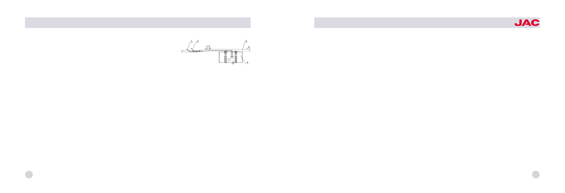
1尧fuel return line; 2尧fuel inlet line;
3尧frame; 4尧fuel tank

schematic diagram of

fuel supply system

24

HFC1020

series trucks

performance of the engine.
1. Diesel fuel filter: the filter which is
mounted on the left side of the en鄄
gine body can filter out impurity of
small particle to ensure the cleaning
of diesel fuel.
2. Fuel tank: the fuel tank volume of
this series trucks is 90 liters, the tank
cap has lock. And install the filter
gauze inside the fuel filler port to pre鄄
vent impurity of large particle enter鄄
ing into the fuel tank, set oil drain
plug on the bottommost position of
the fuel tank to drain the deposit and
water on the bottom of tank when
cleaning the fuel tank.

Using and maintenance

1. Check the chucking position of
pipeline interface for sealing, reliabil鄄

ity and air leakage.
2. Clean or replace the filter element
of diesel fuel filter periodically ac鄄
cording to rules in the operating
specification of the engine.

25

27

Chassis

Clutch

Brief description of the struc鄄
ture

The clutch equipped for this series
truck is single -plate dry type di鄄
aphragm spring clutch, outside di鄄
ameter of the driven plate is 椎254.
The hydraulic control unit of the
clutch is composed of the clutch
pedal尧oil storage cup尧 release cylin鄄
der (master cylinder)尧 wheel cylinder
and oil pipe. It is shown in the below
figure.

The clutch pressure plate and cover
assembly is fixed to the pressure
cover with a diaphragm spring
through a set of rivet and press out

the pressure plate on the outside
edge. The diaphragm spring is both
pressure element and release ele鄄
ment. Because the diaphragm spring
has good nonlinear characteristic,
the pressure of the diaphragm spring
keep steady, transfer the engine
torque stably, and the releasing force
is small, if equipped with hydraulic
control unit the force should be less.
The two -stage torsion damper and
autocompensation absorbing shock
deoscillator have been fixed on the
driven plate assembly to decrease
the idling vibration and vibration at
ordinary speed commendably. The
spline of the inner hole on the driven
plate is involute type, the small inter鄄
tooth space尧 stable transmission and

1尧pedal 2尧piston 3尧push rod
4尧release cylinder 5尧oil storage cup
6尧oil pipe 7尧air bleed plug
8尧wheel cylinder

9尧release fork

10尧release bearing

schematic diagram of the

hydraulic control unit on the clutch

28

HFC1020

series trucks

wavy spring mounted between two
friction linings effectively decrease
the impact force because of fast
linkage of the clutch. The release
bearing of the clutch is radial thrust
bearing with closed spherical sur鄄
face. It does not need to add oil.
And after wear the clearance can be
eliminated automatically.

Adjustment of the clutch operat鄄
ing system

1. Adjust the limit screw of the clutch
pedal (below figure) to make sure
that the free play of the pedal is 3耀
5mm.
2. Adjust the master cylinder of the
clutch: loosen the locknut on the
push rod of the master cylinder, ro鄄
tate the end of the push rod to con鄄

tact gently with the piston of the
master cylinder, then rotate the push
rod for 3/4 circle in the contrary di鄄
rection, tighten the locknut of the
push rod, now the clearance be鄄
tween the push rod and the piston is
about 0.5耀1mm.
3. Adjust wheel cylinder of the clutch
Take off the return spring of the re鄄
lease fork, push the wheel cylinder
piston to the bottom of the cylinder,
loosen the locknut on the push rod,
push the release fork towards the
backside of the engine to the posi鄄
tion where the release bearing and
the release fork contact barely, turn
the spherical nut until it contacts with
the release fork, then turn back the
spherical nut on the push rod for 3

circles, tighten the nut, install the re鄄
turn spring of the release fork.

4. Bleed air from wheel cylinder of
the clutch
Having air or oil leakage in the hy鄄
draulic pipeline of the clutch is unal鄄
lowed, or else, it can result in the
disability of the pedal尧 deficiency of

clutch pedal

29

the effective travel and incomplete
release of the clutch etc. So the
clutch can not work normally. The
work of air bleeding should be com鄄
pleted by two person in the best, one
person depress the clutch pedal in
the cab, the other bleed the air in the
wheel cylinder. The schematic dia鄄
gram of air bleeding for the clutch
wheel cylinder is shown below.
Take off the rubber cap of the air
bleed screw on the wheel cylinder,
link a plastic pipe on the air bleed
screw, put the other end of the pipe
into the container filled with brake
fluid, depress the clutch pedal sever鄄
al times, fill the master cylinder and
hydraulic pipeline with brake fluid,
then loosen the air bleed screw, air

bubble can be puffed from the oil
ring if there are air in the pipeline.
Depress the clutch pedal several

times again when the pedal has not
reached the floor in the cab, keep
the pressure state of the pedal,
loosen the air bleed screw again and
bleed the air. Repeat the abovemen鄄
tioned operation until the air bubble
disappear from the container filled
with brake fluid, tighten the air bleed
valve and cover the rubber cap. In
the progress of air bleeding, com鄄
pensate the brake fluid into the oil
storage cup until the fluid level reach
the sign of MAX.
Sometimes shortly after air bleeding,
the pedal is disable and found that
there is air bubble discharge when
bleeding air again, the reason is that
there is unsealed place in the
pipeline from the master cylinder to

1尧release fork

2尧dust cover

3尧copper washer 4尧wheel cylinder
5尧wrench

6尧soft plastic pipe

7尧container

8尧braking fluid

schematic diagram of air

bleedingfor clutch wheel cylinder

30

HFC1020

series trucks

the wheel cylinder. In maintenance,
check the aluminum washer on the
oil inlet pipe union of the wheel cylin鄄
der for warp, the washer can not be
replaced by the steel cushion. The
air should be bled after every dis鄄
mantlement of the master cylinder尧
the wheel cylinder or the oil pipe.

Maintenance and adjustment

Long time use or incorrect adjust鄄
ment and incomplete air bleeding of
the clutch can bring the halfway re鄄
lease of the clutch, let the clutch on
the half contact state for a long time,
aggravate the wear of the clutch
pressure plate and friction linings.
The decrepitation尧 burnt and exfolia鄄
tion of the friction lining, and the
burnout of the release bearing also

can result in the abnormal operation
of the clutch. When maintaining, all
kinds of clearance of the clutch must
be adjusted.

Transmission

Brief description of the struc鄄
ture

The transmission equipped for the
chassis of this series truck is manual
discontinuously variable transmission
with fixed shaft gear, and it has five
driving gear position and one reverse
gear position. The synchronizer has
been equipped on the second尧 the
third尧 the fourth and the fifth gear
position. And the synchronizer is
synchromesh gear system. The syn鄄
chronizer for the first gear hositlon

and the reverse gear is holding mesh
gear. Using of the synchronizer on
the transmission can make the shift鄄
ing operation conveniently, decrease
the wear and shock on the gear end,
extend the service life of the gear
tooth, shorten the shifting time, in鄄
crease the average vehicle speed
and reduce the working intensity of
the driver. The gear shifting operation
is accomplished with the shifting
control device of the transmission,
which is shown in the figure on the
next page.

Shifting control device of the
transmission

The shifting control device of the
transmission is long distance soft ca鄄
ble type with high floor and short

31


Content   ..  1293  1294  1295  1296   ..