Isuzu N-Series. Service manual - part 1185


  Index      Isuzu     Isuzu N-Series - service and repair manual


Search            


Content   ..  1183  1184  1185  1186   ..


Isuzu N-Series. Service manual - part 1185


SRS 9B-23

Steering Wheel

Precautions on Service Work

WARNING:

FOLLOW PRECAUTIONS ABOUT SAFETY WHEN
HANDLING DEPLOYED SRS AIRBAG ASSEMBLY.
METAL SURFACE OF SRS AIRBAG ASSEMBLY
WILL BE VERY HOT DIRECTLY AFTER DEPLOY-
MENT. DO NOT TOUCH IT FOR 30 MINUTES AFTER-
WARD. DO NOT PUT THE DEPLOYED SRS AIRBAG
ASSEMBLY NEAR FLAMMABLE MATERIALS. FAIL-
URE TO FOLLOW THIS MAY CAUSE FIRE OR INJU-
RY. IF THE DEPLOYED SRS AIRBAG ASSEMBLY
NEEDS TO BE MOVED BEFORE IT COOLS DOWN,
WEAR GLOVES AND GRASP THE SRS AIRBAG OR
TRIM COVER TO MOVE.

WARNING:

WHEN CARRYING UNDEPLOYED SRS AIRBAG AS-
SEMBLY, BE SURE TO TURN THE TRIM COVER TO-
WARD OUTSIDE TO REDUCE THE POSSIBILITY OF
INJURY IN CASE OF AIRBAG DEPLOYMENT. ALSO,
NEVER GRASP THE HARNESS OR CONNECTOR
OF SRS AIRBAG TO CARRY IT.
WHEN STORING UNDEPLOYED SRS AIRBAG AS-
SEMBLY, OR LEAVE IT UNATTENDED ON WORK-
BENCH OR SOMEWHERE ELSE, BE SURE TO TURN
THE TRIM COVER UPWARD TO REDUCE THE POS-
SIBILITY OF INJURY IN CASE OF AIRBAG DEPLOY-
MENT.

Caution:

If deployment occurs, replace the coil assembly.

Removal

1. Stop the function of SRS. (Refer to “Procedure to

stop the function of SRS”.)

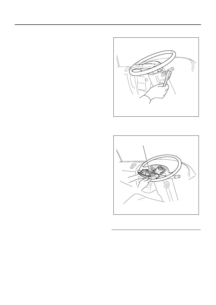
2. Loosen the mounting bolt from the back of steering

wheel assembly using TORX

®

 driver or equivalent

to remove SRS airbag assembly.

3. Disconnect the 2-pole connector (yellow) and horn

harness located in the back of airbag assembly
and remove the airbag.

Legend

1. Airbag harness connector

4. Remove the nut which installs steering wheel.

N9A0044E

1

N9A0045E

9B-24 SRS

5. Put the setting marks on steering wheel and shaft

in order to reassemble parts to the original position.

Legend

1. Setting mark

6. Set tires in straight position before removing steer-

ing wheel. Install the steering wheel puller (5-8840-
2035-0) to steering wheel and remove it.

7. After removing the cover of harness through hole,

put wire into wheel to remove steering wheel.

Caution:

Steering shaft has function as shock absorber. Do not
apply a force in the direction of steering wheel shaft.
When removing the steering wheel, use special tool.

Installation

1. Make sure that tires are in the straight position.
2. While checking the engagement in canceller of

flasher, install steering wheel straight and align the
setting marks.

N9A0050E

1

N9A0051E

SRS 9B-25

Legend

1. Front of steering wheel
2. Steering wheel
3. Connector holder portion
4. Airbag harness

5. Connector
6. Back side of SRS airbag
7. Forward direction of SRS airbag

3. Tighten the mounting nut which installs steering

wheel to the specified torque.

Tighten:
Nut to 42.0 

± 6.8 N⋅m (4.3 ± 0.7 kg⋅m / 31.0 ± 5.0 lb⋅ft)

4. Put the harness through the harness through hole

and assembly the cover.

5. Connect the 2-pole connector (yellow) and horn

harness located in the back of SRS airbag.

6. Secure the connector and harness.
7. Install the SRS airbag to steering wheel and tighten

the bolt to the specified torque.

Tighten:
Bolt to 8.0 

± 2.0 N⋅m (0.8 ± 0.2 kg⋅m / 5.9 ± 1.5 lb⋅ft)

WARNING:

NEVER USE SRS AIRBAG OF OTHER VEHICLE. BE
SURE TO CONFIRM THE PART NUMBER TO USE
APPROPRIATE SRS AIRBAG.

8. Resume the function of SRS. (Refer to “Procedure

to resume the function of SRS”.)

Special tool

5-8840-2035-0 Steering wheel puller

1

2

4

5

6

3

7

N9A0046E

N9A0050E

9B-26 SRS

N9A0052E


Content   ..  1183  1184  1185  1186   ..