Content .. 1153 1154 1155 1156 ..
Isuzu N-Series. Service manual - part 1155
8-332 CAB AND CHASSIS ELECTRICAL
Installation
To install, follow the removal steps in the reverse order.
Warning Light Bulb, Indicator Light Bulb and Il-
lumination Light Bulb
Removal
Preparation:
Disconnect the battery ground cable.
1. Meter Assembly
Refer to “METER ASSEMBLY” in this section.
2. Socket and Bulb
Hold the bulb socket by hand and rotate it counter-
clockwise to remove them from the meter body.
3. Bulb
Pull out the bulb from the socket.
Installation
To install, follow the removal steps in the reverse order.
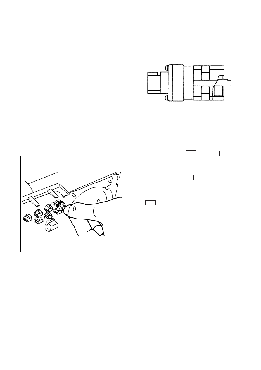
Vehicle Speed Sensor
The vehicle speed sensor is installed on the rear portion
of the transmission or transfer case.
The number of pulses generated is four pulses per one
rotation of the pinion shaft.
Inspection
1. Connect a resistance of 390
Ω±5%, 2W between
connector terminal 1
and battery (+) terminal
and connect the connector terminal 2
to the
battery (
−) terminal.
Caution:
Be extremely careful not to connect the battery (+) ter-
minal to the connector 3
.
This may damage the vehicle speed sensor.
2. Rotate the shaft of the vehicle speed sensor slowly
and measure the voltage between 3
and 2
with a digital tester.
The voltage, with one rotation of shaft, fluctuates four
times in the following range: 10 to 14V
↔ 24 or less.
Replace the sensor when the result of inspection is
found abnormal.
Legend
1. Meter Assembly
2. Meter Glass
3. Meter Plate
4. Warning Lens
N8A0344E
N8A0345E
J-32
J-32
J-32
J-32
J-32