Isuzu N-Series. Service manual - part 112


  Index      Isuzu     Isuzu N-Series - service and repair manual


Search            


Content   ..  110  111  112  113   ..


Isuzu N-Series. Service manual - part 112


SERVICE INFORMATION 00-21

• NPS

• Wishbone Suspension

Notice:
Turn the steering wheel with the brake pedal depressed
using brake pedal pusher.

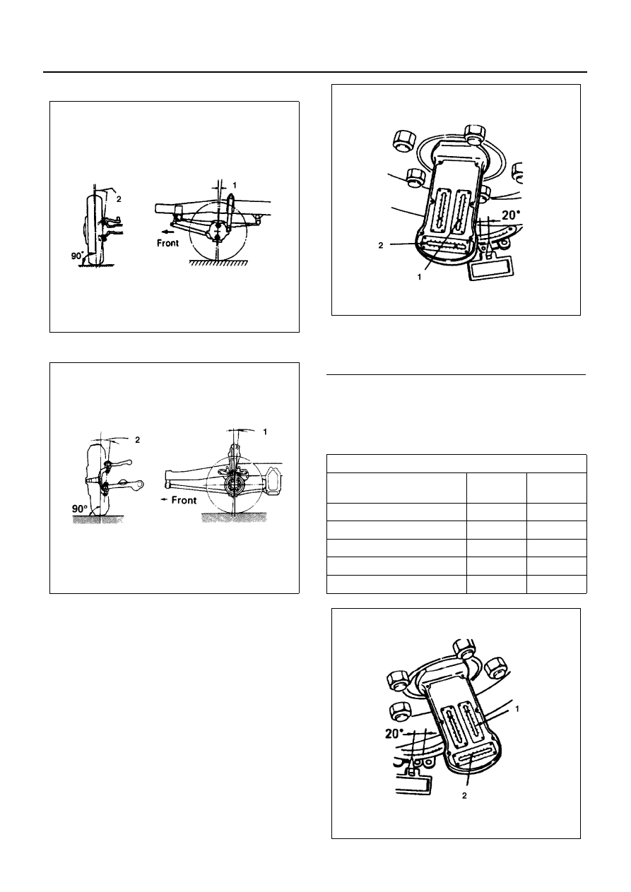
2. When the front wheels are turned 20 degrees, cal-

ibrate the caster and king pin scales to zero turning
the camber, caster and king pin gauge adjuster.

3. Turn the steering wheel in the opposite direction

until the front wheels are steered 20 degrees in the
opposite direction. Reading of the caster and king
pin scales directly indicates the caster and king pin
inclination angles being checked.

N3A0028E

N3A0029E

Legend

1. Caster angle
2. King pin inclination

Caster Angle and King Pin Inclination

(deg.)

Caster 

Angle

King Pin 

Inclination

NHR

1

°30′±1°

7

°15′

NKR Rigid Suspension

3

°00′±1°

12

°00′

NPR, NQR

2

°45′±1°

12

°00′

Wishbone Suspension

1

°00′±1°

9

°45′±30′

NPS

2

°00′±1°

7

°15′

N3A0030E

N3A0031E

00-22 SERVICE INFORMATION

Adjustment
Rigid Suspension
The camber, caster and king pin inclination are built into
front end and are not adjustable. If the camber, caster or
king pin inclination is found to be out of alignment, check
to locate the cause of trouble against the listing below
and replace the parts necessary.

• Front springs for weakening 
• Front I-beam (axle case) for distortion
• Bushing in king pin, King pin bearings for wear or

determination

Wishbone Suspension

1. Set the jack under the cross member of the sus-

pension and then raise the lower link with the jack
and retain the jack with applied in the place.

2. Remove the shock absorber.
3. Attach the fulcrum pin and loosen the bolts to the

degree that it will not fall a part to adjust the camber
angle using the shims.

Camber Angle
If the number of shims are evenly increased both at fore
and aft, the camber angle becomes acute, while if de-
creased, the angle becomes obtuse.
Caster Angle
When the caster angle is obtuse, increase the number
of shims at the fore side, while the angle is acute, in-
crease the number of shims at the aft side.

Thickness of Shims Available
0.8 mm (0.031 in), 1.6 mm (0.063 in), 3.2 mm (0.126 in)
Conditions Where The Shims are Used
Numbers of Shims: 4 or less
Thickness: 9.6 mm (0.378 in) or less
Difference of Thickness (between Front and Rear): 4.8
mm (0.189 in) or less
In case the shim has already reached at the limitation in
its number or its thickness, decrease the number of
shims at the aft side to adjust the obtuse caster angle,
while decrease the number at the fore side to adjust the
acute caster angle.

Notice:
Since the number of shims needed for caster angle ad-
justment varies depending on the conditions of the car,
perform the adjustment procedures which are the most
suitable for the car conditions.

4. Tighten the mounting bolts of the front shock ab-

sorber.

Tighten:

• Shock absorber bolt and nut to

Upper: 21 N

⋅m (2.1 kg⋅m / 16 lb⋅ft)

Lower: 103 N

⋅m (10.5 kg⋅m / 76 lb⋅ft)

Legend

1. Caster angle
2. King pin inclination

N3A0033E

N3A0034E

SERVICE INFORMATION 00-23

Measurement of Side Slippage
When inspection and adjustments of toe-in, camber,
caster and king pin inclination are completed, check for
side slippage using a side slip tester.
Roll the wheels over the side slip tester as slowly as
possible and take reading on the tester, If the amount of
side slippage is in excess of 5 mm per 1 m, recheck the
wheel alignment.
Side Slippage
Limit: 5.0 (0.197) Per 1m

Front and Rear Suspension

Suspension Function

Check the following items.

• Leaf spring breakage
• Body inclination
• Reduction of ground clearance

Lubrication

Lubricate the following points with multi- purpose type
grease.

• Spring Pin (NPS only)

N3A0035E

N3A0036E

N3A0037E

N3A0039E

00-24 SERVICE INFORMATION

• Shackle Pin (NPS only)

• Upper Arm (for Wishbone Suspension)

Wheel and Tires

Wheel Nut Retightening

Retighten the wheel nuts to specified torque in se-
quence as shown in the figure.

Tighten:

• Front wheel nut to

NHR / NKR single tire, NKR flat low: 167 N

⋅m (17

kg

⋅m / 123 lb⋅ft)

Except above models: 441 N

⋅m (45 kg⋅m / 325 lb⋅ft)

• Rear wheel nut to

NHR / NKR single tire: 167 N

⋅m (17 kg⋅m / 123 lb⋅ft)

NHR dual tire, NKR flat low: 294 N

⋅m (30 kg⋅m / 217

lb

⋅ft)

Except above models: 441 N

⋅m (45 kg⋅m / 325 lb⋅ft)

N3A0040E

N3A0041E

N3A0042E

N3A0043E


Content   ..  110  111  112  113   ..