Isuzu N-Series. Service manual - part 111


  Index      Isuzu     Isuzu N-Series - service and repair manual


Search            


Content   ..  109  110  111  112   ..


Isuzu N-Series. Service manual - part 111


SERVICE INFORMATION 00-17
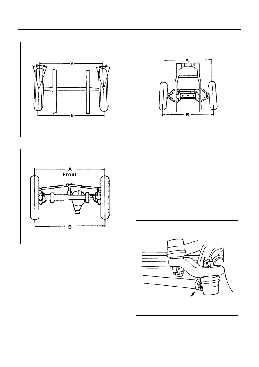
• Rigid Suspension

• NPS

• Wishbone Suspension

Adjustment

1. Loosen the lock nuts on the tie rod or outer truck

rod ends.

2. Adjust length of the tie rod by turning the connect-

ing rod on outer truck rod.

3. Tighten the lock nuts to specified torque.

Tighten:

• Lock nut to

Rigid Suspension, NPS: 113 N

⋅m (11.5 kg⋅m / 183

lb

⋅ft)

Wishbone Suspension: 167 N

⋅m (17.0 kg⋅m / 123

lb

⋅ft)

• Rigid Suspension

N3A0012E

N3A0013E

N3A0014E

N3A0015E

00-18 SERVICE INFORMATION

• NPS

• Wishbone Suspension

Turning Radius

1. Position a suitable piece of wood equivalent in

thickness to the turning radius gauge under each
rear wheel.

2. Position each front wheel on a turning radius

gauge by aligning the tire center line with the cen-
ter of the turning radius gauge.

3. Turn the steering wheel clockwise or counterclock-

wise until the front wheels are locked.

Notice:
Turn the steering wheel with the brake pedal depressed
using brake pedal pusher.
Reading of the turning radius gauge directly indicates
the steering angle.

Steering Angle

N3A0016E

N3A0017E

Wishbone Suspension Model

(deg.)

Vehicle Model

Outer

Inner

NKR (7.00-15 Tire)

35.0

38.0

Rigid Suspension Model

(deg.)

Vehicle Model

Outer

Inner

NHR

33.0

37.5

NKR (7.00-15 Tire)

29.5

38.5

NKR (7.00-16 Tire)

27.9

35.5

NPR (7.00-16 Tire)

35.0

47.5

NPR, NQR (7.50-16 Tire)

32.7

42.5

NQR (8.25-16 Tire)

30.0

36.5

NPS

29.8

37.5

N3A0018E

N3A0018E

SERVICE INFORMATION 00-19

Adjustment

1. Loosen the lock nuts on the steering knuckle or the

axle case.

2. Adjust projecting height of the stopper bolts.
3. Tighten the lock nuts to specified torque.

Tighten:

• Stopper bolt to

Rigid suspension: 186 N

⋅m (19.0 kg⋅m / 137 lb⋅ft)

NPS: 49 N

⋅m (5.1 kg⋅m / 36 lb⋅ft)

Wishbone suspension: 82 N

⋅m (8.4 kg⋅m / 61 lb⋅ft)

• Rigid Suspension

• NPS

• Wishbone Suspension

Camber Angle

All Model except NPS
Toe-in can be checked on the gauge simultaneously.

1. When inspection of turning radius is completed,

calibrate the scale of the turning radius gauge to
zero.

2. Remove the front hub cap.

Install camber, caster and king pin inclination
gauge on end of the knuckle spindle horizontally.

Notice:
When removing hub cap, take care so as not to cause
damage to gauge fitting face at end of the spindle. If end
of the spindle has been scratched or damaged, correct
before setting the gauge.

N3A0020E

N3A0021E

Legend

1. Camber angle

N3A0022E

N3A0023E

00-20 SERVICE INFORMATION

NPS
Remove the free wheel hub lock cover assembly, then
install gauge adapter on end of the knuckle spindle. In-
stall camber, caster and king pin inclination gauge on
end of gauge adapter.
Gauge Adapter: 5-8840-2188-0

3. Reading of the camber scale directly indicates the

camber angle (1).

• NHR, NKR, NPR and NQR

• NPS

Caster Angle and King Pin Inclination

The caster angle and king pin inclination can be
checked on the gauge simultaneously.

1. When inspection of camber angle is completed,

calibrate the scale of the turning radius gauge to
zero and turn the steering wheel clockwise (coun-
terclockwise for checking caster angle (1) and king
pin inclination (2) on the left side front wheel) until
the front wheels are steered 20 degrees from the
straight-ahead position.

• Rigid Suspension

Legend

1. Camber angle
2. Gauge adapter
3. Wheel alignment tester

Camber Angle

(deg.)

NHR Rigid Suspension

1

°15′±45′

Rigid Suspension (except NHR)

0

°15′±45′

Wishbone Suspension, NPS

0

°15′±45′

N3A0024E

N3A0025E

N3A0026E

N3A0027E


Content   ..  109  110  111  112   ..