Isuzu engine 4j series. Service manual - part 52


  Index      Isuzu     Isuzu engine 4j series - manual


Search            


Content   ..  50  51  52  53   ..


Isuzu engine 4j series. Service manual - part 52


6A1 – 76  4JB1/4JB1T/4JB1TC/4JG2 - ENGINE

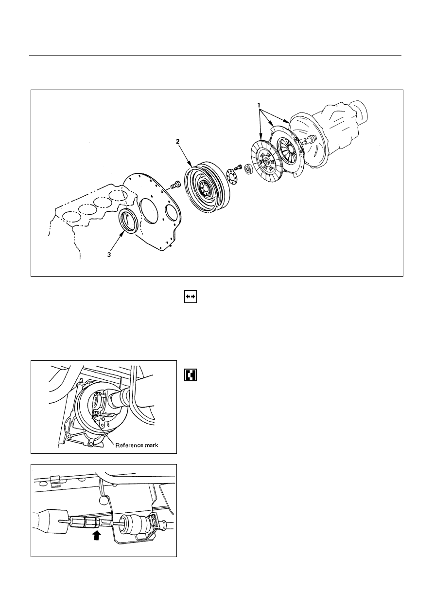
CRANKSHAFT REAR OIL SEAL (Gear & Belt Drive Type)

REMOVAL

Preparation:

Disconnect battery ground cable

1. Transmission and Clutch Assembly

Raise vehicle and support with suitable safely.

1) Transmission

!

Transmission

Reference mark the flange yoke to the parking brake
drum.

Disconnect the propeller shaft at flange yoke.

Put aside the propeller shaft and tie it to the frame so
that it does not interface with servicing work.

"

Parking Brake Cable

Move the joint cover.

Disconnect the joint bolt.

Remove the clip then disconnect the cable from the
bracket.

6A1-76-1.tif

6A1-76-2.tif

6A1-76-3.tif

Removal steps

1.  Transmission and clutch Assembly
2. Flywheel
3.  Rear oil seal

Installation steps

To install, follow the removal steps in the
reverse order.

4JB1/4JB1T/4JB1TC/4JG2 – ENGINE  6A1 – 77

#

Wiring Connector

Disconnect the wiring connectors from the car speed
sensor, the neutral switch and the back-up light switch.

$

Shift Cable and Select Cable

Disconnect the shift cable and select cable on the
transmission side.

%

Clutch Slave Cylinder

Remove the clutch pipe fixing clips and the clip
bracket (Right hand drive models only).

Remove the slave cylinder assembly with the flexible
hose attached, and then tie it to the frame so that it
does not interface with servicing work.

&

Exhaust Brake Assembly

'

Front Exhaust Pipe

6A1-77-1.tif

6A1-77-2.tif

6A1-77-3.tif

6A1-77-4.tif

6A1 – 78  4JB1/4JB1T/4JB1TC/4JG2 - ENGINE

(

Transmission Assembly

NOTE:

The exhaust pipe bracket, the gear control bracket
and the clips are sometimes installed in the wrong
position or direction confusedly. To prevent incorrect
installation of these parts, put a correct installation
mark on them.

Support the transmission with mission jack.

CAUTION:

To prevent the falling of the transmission, tie it firmly
to the jack with a chain or belt.

Do not allow transmission to hang unsupported from
clutch. Damage to the clutch assembly will result.

Remove the nuts of the transmission mounting bracket
on the crossmember side.

Engine and transmission angles may need to be
adjusted for removal.

Hold the rear section of the engine by the jack or hoist.

CAUTION:

When lifting the engine by the jack, use wood blockes
to prevent any possible damage to the oil pan.

Remove transmission fastening bolts.

Pull out the transmission assembly rearward.

)

Mounting Bracket

6A1-78-1.tif

4JB1/4JB1T/4JB1TC/4JG2 – ENGINE  6A1 – 79

2) Clutch

Raise vehicle and support with suitable safety stands.

CAUTION:

Do not let clutch fluid remain on a painted surface,
Wash it off immediately.

!

Pressure Plate Assembly

"

Driven Plate Assembly

Use the pilot aligner to prevent the driven plate
assembly from falling free.
Pilot Aligner: 5-5825-3001-0

Mark the flywheel and pressure plate lug for alignment
when installing.

Loosen the pressure plate assembly fixing bolts.

2. Flywheel

3. Rear Oil Seal

With the oil seal pushed in deep, install the special tool
as shown in the illustration to remove the oil seal.

Rear oil seal Remove: 5-8840-2360-0

NOTE:

Take care not to damage the crankshaft or oil seal
retainer when removing oil seal.

6A1-79-1.tif

6A1-79-2.tif


Content   ..  50  51  52  53   ..