Harley Davidson 1986-2003 XL/XLH Sportster. Service Manual - page 17


  Главная      Harley Davidson     Harley Davidson 1986-2003 XL/XLH Sportster. Service Manual


Search            copyright infringement  


Content      ..     15      16      17      18     ..


Harley Davidson 1986-2003 XL/XLH Sportster. Service Manual - page 17


CAUTION

While the cylinder is removed, use care when
working around the cylinder studs to avoid
bending or damaging them. A bend could
cause a stud failure later during engine oper-
ation.

10. Remove the pistons and rings as described in this chap-
ter.
11. Repeat Steps 1-10 for the remaining cylinder.

Inspection

To obtain an accurate cylinder bore measuremnt, the cyl-

inder must be secured between torque plates. Torque plates
are available from several sources. This arrangement simu-
lates the distortion imparted on a cylinder when it is
clamped down by the cylinder head and the cylinder bolts
are tightened to the specified torque. Measurements made
without the engine torque plate can vary by 0.001 in. (0.025
mm). If you do not have access to the torque plates, refer
service to a dealership.
1. Remove all gasket residue from both cylinder gasket
surfaces.
2. Thoroughly clean the cylinder with solvent and dry with
compressed air.
3. Lightly coat the cylinder bore with clean engine oil to
prevent rust.
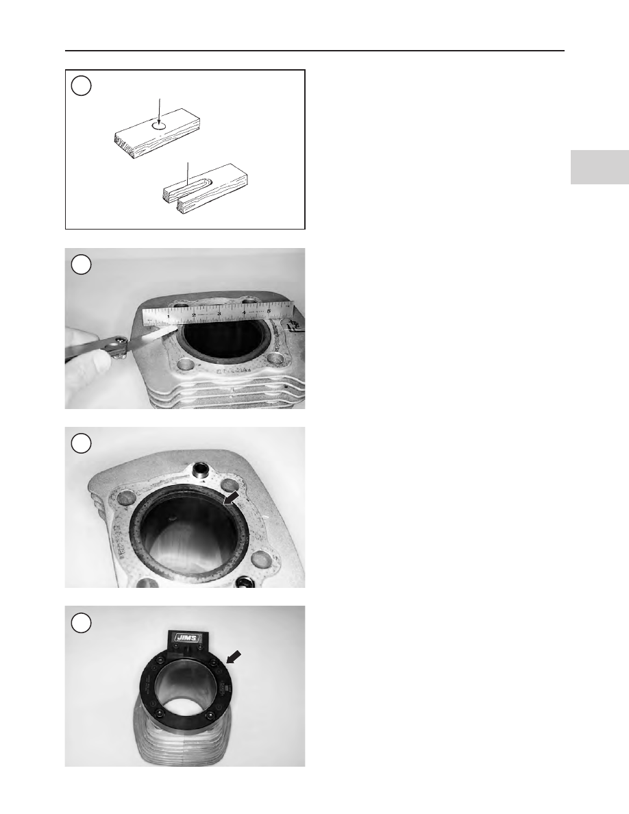
4. Check the top (Figure 102) and bottom cylinder block
gasket surfaces with a straightedge and feeler gauge. Re-
place the cylinder and piston if the following warp limits
are exceeded:

a. Top cylinder surface: 0.006 in. (0.152 mm).
b. Bottom cylinder surface: 0.008 in. (0.203 mm).

5. Check the cylinder walls (Figure 103) for scuffing,
scratches or other damage.
6. Install the torque plates onto the cylinder (Figure 104)
following the manufacturer’s instruction.
7. Measure the cylinder bore at the points shown in Figure
105
. Initial measurement should be made at a distance of
0.500 in. (12.7 mm) below the top of the cylinder. The
0.500 in. (12.7 mm) depth represents the start of the ring
path area; do not take readings that are out of the ring path
area.
8. Measure in two axes—in line with the piston pin and at
90

°

to the pin. If the taper or out-of-round is greater than

specifications (Table 2), rebore the cylinders to the next
oversize and install new pistons and rings. Rebore both cyl-
inders even though only one may be worn.
9. Have a dealer or machine shop confirm all cylinder mea-
surements before ordering replacement parts.

CAUTION

Hot soapy water is the only solution that will
completely clean the cylinder walls. Solvent
and kerosene cannot wash fine grit out of the
cylinder crevices. Residual abrasive grit in

ENGINE TOP END

181

4

101

102

103

104

Drill hole in center

Cut away portion

the cylinder wall will cause premature engine
wear.

10. After the cylinders have been serviced, wash each cyl-
inder in hot, soapy water. This is the only way to clean the
cylinder walls of the fine grit material left from the boring
or honing job. After washing the cylinder bore, run a clean
white cloth through it. If the cloth shows traces of grit or oil,
the cylinder is not clean enough. Repeat until the cloth co-
mes out clean. When the cylinder wall is clean, dry with
compressed air and then lubricate with clean engine oil to
prevent the cylinder wall from rusting. Repeat for the other
cylinder.

Studs and bolts

The cylinder studs and cylinder head bolts must be in

good condition and properly cleaned prior to installing the
cylinders and cylinder heads.

1. Examine the cylinder head bolts (Figure 106) for head
or thread damage. Replace if necessary.

2. Examine the cylinder studs for bending, looseness or
damage. Replace loose or damaged studs as described in
the

Cylinder Studs

in Chapter Five. If the studs are in good

condition, perform Step 3.

CAUTION

The cylinder studs, cylinder head bolts and
washers are made of hardened material. Do
not substitute these items with a part made of
a lower grade material.

3. Cover the crankcase openings with shop rags to prevent
debris from falling into the engine.

4. Remove all carbon residue from the cylinder studs and
cylinder head bolts as follows:

a. Apply solvent to the cylinder stud and mating cylin-

der head bolt threads and thread the bolt onto the
stud.

b. Hand turn the cylinder head bolt back and forth to

loosen and remove carbon residue from the threads.
Remove the bolt from the stud. Blow both thread sets
with compressed air.

182

CHAPTER FOUR

105

Bolt

Torque plate

Cylinder

Torque plate

Nut

Top

Torque plate

Middle

Bottom

c. Repeat until both thread sets are free of all carbon res-

idue.

d. Spray the cylinder stud and cylinder head bolt with

electrical contact cleaner and blow dry.

e. Set the cleaned bolt aside and install it on the same

stud when installing the cylinder head.

5. Repeat Step 4 for each cylinder stud and cylinder head
bolt set.

Installation

Refer to Figure 98.

1. Install the pistons and rings as described in this chapter.

2. Check that all of the piston pin retaining rings (Figure
107
) have been properly installed.
3. Remove all gasket residue and clean the cylinders as de-
scribed in

Inspection

in this section.

4. Install the dowel pin (A, Figure 108), if removed. Install
new O-ring
5. Install a new cylinder base gasket (B, Figure 108) onto
the crankcase. Make sure all holes line up properly.
6. Turn the engine over until the piston is at top dead center
(TDC).
7. Lubricate the cylinder bore and piston liberally with
clean engine oil.
8. Slide the protective hoses off of the cylinder studs.
9. Position each piston ring so the end gap of adjacent rings
is at least 90

°

apart (Figure 109). Ring gaps must not be

within 10

°

of the piston’s thrust face.

10. Compress the rings using a ring compressor (Figure
110
).

ENGINE TOP END

183

4

106

107

108

109

110

11. Install the cylinders in their original positions. Align
the cylinder with the cylinder studs and slide it down (Fig-
ure 111
) until it is over the top of the piston. Continue slid-
ing the cylinder down and past the rings. Once the rings are
positioned in the cylinder, remove the ring compressor.

12. Continue to slide the cylinder down until it bottoms on
the crankcase.

13. Repeat to install the remaining cylinder.

14. Install the cylinder heads as described in this chapter.

PISTONS AND PISTON RINGS

Refer to Figure 98.

Piston and Piston Rings Removal

1. Remove the cylinder head and cylinder as described in
this chapter.

2. Stuff clean shop rags into the crankcase opening to pre-
vent objects from falling into the crankcase.

3. Install a hose around each stud to protect the piston and
studs from damage.

4. Install a piston holding tool to stabilize the piston. Con-
struct the tool from wood as shown in Figure 101.

5. Lightly mark the pistons with an

F

(front) or

R

(rear) so

they may be installed into the correct cylinder.

WARNING

Because the piston pin retaining rings are
highly compressed in the piston pin ring
groove, safety glasses must be worn during
their removal and installation.

6. It is necessary to remove the retaining ring (Figure 112)
on one side to remove the piston. Using a suitable tool, pry
the retaining ring out of the piston. Place a finger over the
hole to help prevent the ring from flying out during re-
moval. Mark the piston rings so they can be reinstalled in
their original connecting rods.

7. Support the piston and push out the piston pin (Figure
113
). If the piston is difficult to remove, use a homemade
tool as shown in Figure 114.

NOTE

If reusing the piston rings, identify and store
the rings in a container so they can be rein-
stalled in their original ring grooves and on
their original pistons.

8. Remove the old rings using a ring expander tool (Figure
115
) or spread them with your fingers (Figure 116) and re-
move them.

9. Inspect the pistons, piston pins and pistons rings as de-
scribed in this section.

184

CHAPTER FOUR

111

112

113

114

Pin

Piston pin

Piston
pin

Pipe

Nut

Washer

Threaded
rod

Piston Inspection

CAUTION

Do not damage the piston when removing
carbon deposits. Do not use a wire brush to
clean the ring grooves or piston sides. Do not
remove carbon from the piston sides above
the top ring groove or from the top of the cyl-
inder bore. Carbon removal from these areas
may cause increased oil consumption.

1. Carefully clean the carbon from the piston crown (Fig-
ure 117
) with a soft scraper. Do not remove or damage the
carbon ridge around the circumference of the piston above
the top ring.

2. Using a broken piston ring, remove all carbon deposits
from the piston ring grooves (Figure 118). Do not remove
aluminum from the piston ring grooves when cleaning
them.

3. After cleaning the piston, examine the crown. The
crown should show no signs of wear or damage. If the
crown appears pecked or spongy-looking, check the spark
plug, valves and combustion chamber for aluminum de-
posits. If aluminum deposits are found, the engine is over-
heating.

4. Examine each ring groove for burrs, dented edges or
other damage. Pay particular attention to the top compres-
sion ring groove as it usually wears more than the others. If
the oil ring groove is worn or if the oil ring assembly is tight
and difficult to remove, the piston skirt may have collapsed
due to excessive heat and is permanently deformed. Re-
place the piston if damaged.

5. Check the piston skirt for cracks or other damage. If the
piston skirt is worn or scuffed unevenly from side-to-side,
the connecting rod may be bent or twisted. If a piston shows
signs of partial seizure such as aluminum build-up on the
piston skirt, replace the piston.

6. Inspect the retaining ring groove (Figure 119) on each
side for wear, cracks or other damage. If the grooves are
questionable, check the retaining ring fit by installing a new
retaining ring into each groove, then attempt to move the
retaining ring from side-to-side. If the retaining ring has

ENGINE TOP END

185

4

115

116

117

118

119

any side play, the groove is worn and the piston must be re-
placed.
7. If piston replacement is required, select a new piston as
described in

Piston Clearance

in this section. If the piston,

rings and cylinder are not damaged and are dimensionally
correct, they can be reused.

Piston Pin Inspection

The piston pins used on 883 and 1200 models are differ-

ent. The 1200 model piston pins are marked with a
V-groove in one end of the pin (Figure 120). The 883
model pins are not marked. When purchasing replacement
piston pins, note the difference.
1. Clean the piston pin in solvent and dry thoroughly.
2. Replace the piston pins if cracked, pitted or scored.
3. If the piston pins are visually okay, check their clearance
as described in

Piston Pin Bushing Replacement

in this

section.

Piston Clearance

Piston dimensions are not provided by the manufacturer.

The cylinder bore must be machined to the correct dimen-
sion to provide the desired piston clearance. Refer to Table
for cylinder bore dimension.

Piston Pin Bushing

Inspection

All models are equipped with a bushing (Figure 121) at

the small end of the connecting rod. The bushing is reamed
to provide correct piston pin clearance.
1. Inspect the piston pin bushing for wear or damage. Also
check the bushing for a loose fit; the bushing must be a tight
fit in the connecting rod.
2. Measure the piston pin outer diameter where it rides in
the bushing (Figure 122).
3. Measure the piston pin bushing inner diameter.
4. Subtract the pin outer diameter from the bushing inner
diameter to obtain the piston pin clearance.
5. Replace the pin and bushing if the clearance meets or
exceeds the service limit in Table 2.

Replacement

1. The following tools are required to replace and ream the
piston pin bushings. The clamp tool is only required if the
bushing is being replaced with the crankcase assembled. If
these tools are not available, have a shop with the proper
equipment perform the procedure.

a. Connecting rod clamp tool (part No. 1284 or HD-

95952-33C).

b. Connecting rod bushing tool (part No. 95970-32C).
c. Bushing reamer tool (part No. 1726-2).

d. Connecting rod bushing hone (part No. HD-35102).

e. Honing oil.

2. Remove two of the plastic hoses protecting the cylinder
studs (B, Figure 100).

3. Install the connecting rod clamping tool as follows:

a. Install the clamp portion of the connecting rod

clamping tool around the connecting rod so the slots

186

CHAPTER FOUR

120

“V” groove

121

122

engage the cylinder head studs. Do not damage the
studs.

b. Position the threaded cylinders with the knurled end

facing up and install the cylinders onto the studs.
Tighten the clamp securely.

c. Alternately tighten the thumbscrews on the side of

the connecting rod. Do not turn only one thumb-
screw, as this will move the connecting rod off center
and tightening the other thumbscrew will cause the
connecting rod to flex or bend.

4. Cover the crankcase opening to keep bushing particles
from falling into the engine.
5. Assemble the removal tool per the manufacturer’s in-
structions (Figure 123) and remove the bushing.

CAUTION

When installing the new bushing, align the oil
slot in the bushing (A,

Figure 124

) with the

oil hole in the connecting rod (B).

6. Replace the bushing using the connecting rod bushing
tool (C, Figure 124) following the tool manufacturer’s in-
structions. The new bushing must be flush with both sides
of the connecting rod.
7. Ream the piston pin using the bushing reamer tool (Fig-
ure 125
) following the manufacturer’s instructions.
8. Hone the new bushing to obtain the piston pin clearance
specified in Table 2. Use honing oil, not engine oil, when
honing the bushing to size.
9. Install the piston pin through the bushing. The pin
should move through the bushing smoothly. Confirm pin
clearance using a micrometer and bore gauge.

CAUTION

If the bushing clearance is less than 0.00125
in. (0.0317 mm), the pin may seize on the rod,
causing engine damage.

10. Remove the shop rags from the crankcase openings
making sure no debris falls into the opening and replace
them with clean rags.

Inspection

1. Clean the piston ring grooves of all carbon residue as de-
scribed in

Piston Inspection

in this section.

2. Inspect the ring grooves for burrs, nicks, or broken or
cracked lands. Replace the piston if necessary.
3. Insert one piston ring into the top of its cylinder and tap
it down about 1/2 in. (12.7 mm) with the piston to square it
in the bore. Measure the ring end gap with a feeler gauge
(Figure 126) and compare with specifications in Table 2.
Replace the piston rings as a set if any one ring end gap
measurement is excessive. Repeat for each ring.
4. Roll each compression ring around its piston groove as
shown in Figure 127. The ring should move smoothly with
no binding. If a ring binds in its groove, check the groove
for damage. Replace the piston if necessary.

ENGINE TOP END

187

4

123

124

125

126

Installation

Each piston is equipped with three piston rings: two com-

pression ring (Figure 128) and one oil ring assembly (Fig-
ure 129
). The top compression ring is not marked. The
second compression ring must be installed with its dot mark
facing up.

Used piston rings must be installed on their original pis-

tons and in their original grooves.

CAUTION

When installing oversize compression rings,
check the number to make sure the correct
rings are being installed. The ring numbers
should be the same as the piston oversize
number.

1. Wash the piston in hot, soapy water. Then rinse with
cold water and blow dry. Make sure the oil control holes in
the lower ring groove are clear and open.
2. Clean the piston rings carefully and dry with com-
pressed air.
3. Install the oil ring assembly as follows:

a. The oil ring consists of three rings: a ribbed spacer

ring (A, Figure 129) and two steel rings (B).

b. Install the spacer ring into the lower ring groove. Butt

the spacer ring ends together. Do not overlap the ring
ends.

CAUTION

Expand the rings just enough to install
them. Expanding them too much distorts the
rings.

c. Insert one end of the first steel ring into the lower

groove so that it is below the spacer ring. Then spiral
the other end over the piston crown and into the
lower groove. To protect the ring end from scratch-
ing the side of the piston, place a piece of shim stock
or a thin, flat feeler gauge between the ring and pis-
ton.

d. Repeat sub-step c to install the other steel ring above

the spacer ring.

CAUTION

When installing the compression rings, use a
ring expander as shown in

Figure 115

. Do

not expand the rings any more than necessary
to install them.

4. Install the second compression ring as follows:

a. The second compression ring has a dot mark (Figure

130).

b. Install the second compression ring so that the dot

mark faces upward.

5. Install the top compression ring as follows:

a. The top compression ring is not marked.
b. New upper compression rings can be installed with

either side facing up. Used upper compression rings

188

CHAPTER FOUR

127

128

129

130

should be installed with their original top side facing
up.

6. Check ring side clearance with a feeler gauge as shown
in Figure 131. Check side clearance in several spots around
the piston. If clearance meets or exceeds service limit in Ta-
ble 2
, note the following:

a. If the ring grooves were not cleaned, remove the

rings and clean the grooves. Then reinstall the rings
and recheck clearance.

b. If reusing the old rings, replace the rings and or the

piston.

c. If using new rings, replace the piston.

7. Stagger the ring gaps around the piston as shown in Fig-
ure 132
. The ring gaps must not be within 10

°

of the pis-

ton’s thrust face centerline.

Piston Installation

1. Cover the crankcase openings with a clean shop towel to
avoid dropping debris into the engine.
2. Install a new piston pin retaining ring into one groove in
the piston. Make sure the ring seats in the groove com-
pletely.
3. Coat the connecting rod bushing and piston pin with as-
sembly oil.

NOTE

The piston markings described in Step 4 are
for original equipment pistons. If installing
aftermarket pistons, follow the manufac-
turer’s directions for piston alignment and in-
stallation.

4. Place the piston onto the connecting rod with the arrow
mark facing forward (Figure 133). Install used pistons on
their original connecting rods; refer to the marks made on
the piston during removal. Oversize pistons must be in-
stalled in the cylinder (front or rear) that they were origi-
nally fitted to during the boring process.
5. Insert the piston pin through the piston. Hold the rod so
that the lower end does not take any shock. Push the piston
pin in until it contacts the retaining ring on the opposite
side.
6. Install the remaining new piston pin retaining ring (A,
Figure 134). Make sure the ring end gap does not coincide
with the notch on the side of the piston (B, Figure 134).
Make sure the retaining ring seats in the groove completely.
7. Install the cylinders as described in

Cylinder

section in

this chapter.

OIL TANK AND OIL LINES

Hose Clamps

CAUTION

Discard removed hose clamps. Do not attempt
to reuse removed clamps.

ENGINE TOP END

189

4

131

132

133

The oil hoses are secured by band-type hose clamps (A,

Figure 135). Use diagonal pliers or other suitable tool to sep-
arate the clamp bands, then remove the clamp. Use hose
clamp pliers (part No. HD-97087-65B or equivalent) to
compress the clamp bands during installation.

NOTE

End cutting pliers (B,

Figure 135

) may be

modified to compress the band clamps. Make
sure to test the performance of the tool by

checking the fit and integrity of the installed
clamp.

Oil Lines

Refer to Figures 136-138 for hose identification and

routing. Replace all band-type clamps with new ones as de-
scribed in this section. The threaded hose end fittings are

190

CHAPTER FOUR

134

135

136

OIL HOSE ROUTING (1986-1990 MODELS)

Air cleaner

Oil tank

Transmission
vent line

Oil filter

Main oil feed

Oil tank return
Vent line

Oil pump

Frame (front)

not replaceable; the fittings and hose are available only as a
unit assembly.

Oil Tank

NOTE

An improved oil tank is available to replace
the oil tank on 1986-1993 models.

Removal/installation

Refer to Figures 136-138 when performing the follow-

ing procedure.

1. Drain the oil tank (Chapter Three).

2. Remove the battery (Chapter Twelve).

3. Detach the ignition module connector from the battery
tray by pushing the connector up (Chapter Twelve).

4. Unscrew the fasteners and remove the battery tray. Note
the location of the positive battery cable retainer.

5. Remove the electrical component panel from the frame
(Chapter Twelve).

6. Refer to Figure 139. Detach the vapor valve clip, dis-
connect the upper end of the valve from the hose and move
the vapor valve out of the way.

ENGINE TOP END

191

4

137

OIL HOSE ROUTING

(1991-1993 MODELS)

Oil tank

Transmission

Feed

Vent

Return

Starter

Gear case cover

Oil pump

Oil filter
mount

7. On California models, move the carbon canister purge
hose out of the vapor valve bracket groove (Chapter Ten or
Chapter Eleven).
8. On top of the oil tank cut the wiring harness cable strap.
9. Remove the oil tank mounting locknuts.
10. Mark and identify the oil hoses before detaching them
from the oil tank. Move the oil tank sufficiently for access
to the oil hoses, then disconnect the oil hoses from the oil
tank.
11. Remove the oil tank.
12. If necessary, remove the rubber stud mounts from the
oil tank. Replace them if damaged.
13. Reinstall the oil tank by reversing the removal steps
while noting the following:

a. Tighten the oil tank mounting locknuts to 36-60

in.-lb. (4-7 N•m).

b. Make sure the long end of the vapor valve points up.

192

CHAPTER FOUR

138

OIL HOSE ROUNTING (1994-2003 MODELS)

Filler cap
and dipstick

Oil tank

Transmission

Gear case cover

To “A”

Return

Vent

Feed

Oil pump

Starter

Oil filter

139

Vapor valve

Table 1 GENERAL ENGINE SPECIFICATIONS

Type

45°,V-twin, air-cooled

Bore and stroke

883 models

3.000 × 3.812 in.
(76.2 × 96.8 mm)

1100 models

3.350 × 3.812 in.
(85.1 × 96.8 mm)

1200 models

3.498 × 3.812 in.
(88.85 × 96.8 mm)

Displacement

883 models

53.9 cu. in. (883 cc)

1100 models

67.2 cu. in. (1102 cc)

1200 models

73.3 cu. in. (1203 mm)

Compression ratio

All models except 1998-2003 1200S models

9.0:1

1998-2003 1200S models

10.0:1

Compression pressure (at sea level)

approx. 120 psi (828 kPa)

Horsepower

1986-1990

883 models

52 @ 6000 rpm

1100 models

62 @ 6000 rpm

1200 models

68 @ 6000 rpm

1991-1997

883 models

55 @ 6000 rpm

1200 models

65 @ 5200 rpm

1998-2003

883 models

57 @ 6000 rpm

1200 models (except 1200S models)

66 @ 5200 rpm

1200S models

69 @ 5500 rpm

Torque

1986-1990

883 models

53 ft.-lb. (72 N•m) @ 4250 rpm

1100 models

63 ft.-lb. (85.4 N•m) @ 4000 rpm

1200 models

72 ft.-lb. (97.6 N•m) @ 4500 rpm

1991-1992

883 models

55 ft.-lb. (74.5 N•m) @ 4500 rpm

1200 models

71.5 ft.-lb. (97 N•m) @ 4000 rpm

1993-1997

883 models

50 ft.-lb. (68 N•m) @ 4600 rpm

1200 models

71 ft.-lb. (96 N•m) @ 4000 rpm

1998-2003

883 models

53 ft.-lb. (72 N•m) @ 4500 rpm

1200 models (except 1200S models)

72 ft.-lb. (97.6 N•m) @ 4000 rpm

1200S models

76 ft.-lb. (103 N•m) @ 4000 rpm

Table 2 ENGINE SERVICE SPECIFICATIONS

New

Service Limit

in. (mm)

in. (mm)

Connecting rods

Piston pin clearance

0.00125-0.00175

0.002

(0.0318-0.0445)

(0.0508)

Cylinder

Taper

0.002
(0.0508)

Out-of-round

0.003
(0.076)

Gasket surface warp

Top

0.006
(0.152)

Bottom

0.008
(0.203)

Cylinder bore diameter (883 models)*

Standard

3.0005

3.0035

(76.213)

(76.289)

(continued)

ENGINE TOP END

193

4

Table 2 ENGINE SERVICE SPECIFICATIONS

New

Service Limit

in. (mm)

in. (mm)

Cylinder bore diameter (883 models)*

(continued)
Oversize

0.005 in. (0.13 mm)

3.0048

3.0078

(76.322)

(76.398)

0.010 In. (0.25 mm)

3.0098

3.0128

(76.449)

(76.525)

0.020 in. (0.51 mm)

3.0198

3.0228

(76.703)

(76.779)

0.030 in. (0.76 mm)

3.0298

3.0328

(76.957)

(77.033)

0.040 in. (1.02 mm)

3.0398

3.0428

(77.211)

(77.287)

Cylinder bore diameter (1100 models)*

Standard

3.3505

3.3535

(85.103)

(85.179)

Oversize

0.005 in. (0.13 mm)

3.3548

3.3578

(85.212)

(85.288)

0.010 In. (0.25 mm)

3.3598

3.3628

(85.339)

(85.415)

0.020 in. (0.51 mm)

3.3698

3.3728

(85.593)

(85.669)

0.030 in. (0.76 mm)

3.3798

3.3828

(85.847)

(85.923)

0.040 in. (1.02 mm)

3.3898

3.3928

(86.101)

(86.177)

Cylinder bore diameter (1200 models)*

Standard

3.4978

3.5008

(88.844)

(88.920)

Oversize

0.005 in. (0.13 mm)

3.502

3.505

(88.951)

(89.027)

0.010 in. (0.25 mm)

3.507

3.510

(89.078)

(89.154)

0.020 in. (0.51 mm)

3.517

3.520

(89.332)

(89.408)

0.030 in. (0.76 mm)

3.527

3.530

(89.586)

(89.662)

Cylinder head

Gasket surface warp

0.006

0.006

(0.152)

(0.152)

Valve guide fit in head

0.0033-0.0020

(0.084-0.051)

Valve seat fit in head

0.0035-0.0010

(0.089-0.025)

Piston (883 and 1100 models)

Compression ring end gap

0.010-0.023

0.032

(0.254-0.584)

(0.813)

Oil control ring rail end gap

0.010-0.053

0.065

(0.254-1.346)

(1.651)

Compression ring side clearance

Top

0.0020-0.0045

0.0065

(0.051-0.114)

(0.165)

Second

0.0020-0.0045

0.0065

(0.051-0.114)

(0.165)

Oil control ring side clearance

0.0014-0.0074

0.0094

(0.036-0.188)

(0.239)

Piston (1200 models)

Compression ring end gap

0.007-0.020

0.032

(0.178-0.508)

(0.813)

Oil control ring rail end gap

0.009-0.052

0.065

(0.229-1.321)

(1.651)

(continued)

194

CHAPTER FOUR

Table 2 ENGINE SERVICE SPECIFICATIONS

New

Service Limit

in. (mm)

in. (mm)

Piston (1200 models)

Compression ring side clearance

Top

0.0020-0.0045

0.0065

(0.051-0.114)

(0.165)

Second

0.0016-0.0041

0.0065

(0.041-0.104)

(0.165)

Oil control ring side clearance

0.0016-0.0076

0.0094

(0.041-0.193)

(0.239)

Rocker arm

Shaft fit in bushing

0.0005-0.0020

0.0035

(0.013-0.051)

(0.089)

End clearance

0.003-0.013

0.025

(0.08-0.33)

(0.635)

Bushing fit in rocker arm

0.0040-0.0020

(0.102-0.051)

Rocker arm shaft

Shaft fit in cover

0.0007-0.0022

0.0035

(0.018-0.056)

(0.089)

Valves

Guide-to-valve stem clearance

Intake

0.0008-0.0026

0.0035

(0.020-0.066)

(0.089)

Exhaust

0.0015-0.0033

0.0040

(0.038-0.084)

(0.102)

Seat width

0.040-0.062

0.090

(1.016-1.575)

(2.286)

Stem protrusion from cylinder

valve pocket

1.975-2.011

2.031

(50.165-51.079)

(51.587)

Valve spring free length

Outer spring

2.105-2.177

2.105

(53.467-55.296)

(53.467)

Inner spring

1.926-1.996

1.926

(48.92-50.70)

(48.92)

*+-0.0002 in. (0.005 mm)

Table 3 VALVE SPRING COMPRESSION SPECIFICATIONS

Compression

length

Pressure

in. (mm)

lb. (kg)

Outer spring

Intake

Closed

1.751-1.848 (44.46-46.94)

72-92 (32.7-41.7)

Open

1.286-1.383 (32.66-35.13)

183-207 (83.0-93.9)

Exhaust

Closed

1.751-1.848 (44.47-46.94)

72-92 (32.7-41.7)

Open

1.332-1.429 (33.83-36.30)

171-195 (77.6-88.5)

Inner spring

Intake

Closed

1.577-1.683 (40.05-42.74)

38-49 (17.24-22.23)

Open

1.112-1.218 (28.44-30.94)

98-112 (44.45-50.80)

Exhaust

Closed

1.577-1.683 (40.06-42.75)

38-49 (17.24-22.23)

Open

1.158-1.264 (29.41-32.11)

91-106 (41.3-48.1)

ENGINE TOP END

195

4

Table 4 ENGINE TORQUE SPECIFICATIONS

ft.-lb.

in.-lb.

N•m

Breather valve retaining screw

35-55

4-6

Cylinder head bolts*
Engine mounts

Engine bolts

25-30

34-41

Frame bolts

30-35

41-47

Lower rocker cover bolts

5/16 in.

15-18

20-24

1/4 in.

120-156

14-18

Oil tank mounting locknuts

36-60

4-7

Pushrod tube seal plate bolts

15-18

20-24

Rocker cover bolts

120-156

14-18

Spark plug

11-18

15-24

*Refer to text.

196

CHAPTER FOUR


Content      ..     15      16      17      18     ..