Harley Davidson 1986-2003 XL/XLH Sportster. Service Manual - page 16


  Главная      Harley Davidson     Harley Davidson 1986-2003 XL/XLH Sportster. Service Manual


Search            copyright infringement  


Content      ..     14      15      16      17     ..


Harley Davidson 1986-2003 XL/XLH Sportster. Service Manual - page 16


d. Make sure that each pushrod is seated in the top of its

respective tappet.

11. Install the rocker covers as described in this chapter.

12. Install the intake manifold as described in Chapter Ten
or Chapter Eleven.

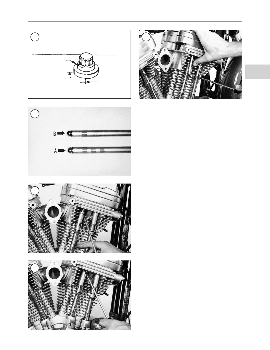
13. On 1986-1990 models, position the upper pushrod
covers using the following procedure:

a. Push the upper pushrod cover up (Figure 53) and

seat it in the cylinder head (Figure 54).

b. Position the spring cap retainer as shown in Figure

55. Place a screwdriver under the retainer and lift the
screwdriver up slightly and slide the retainer into po-
sition.

14. Install the top center engine mount assembly (Figure
56
) as follows:

a. Install the top center engine mount bolts and washers

through the engine mount.

b. Place the shim, if used, onto the top center engine

mount bolts as shown in Figure 56.

NOTE

Three different shim thicknesses are avail-
able: 0.030 in. (0.076 mm), 0.060 in. (1.52
mm) and 0.090 in. (2.27 mm). If the engine
cases, cylinder heads, top center engine
mount or frame were not replaced, the origi-
nal thickness shim can be installed. If one of
these major components was replaced, a dif-
ferent thickness shim may be required.

c. Install the top center engine mount onto the engine.

Insert the two engine mount bolts through the frame
so that the shim does not fall off.

d. Place the nut plate into position (Figure 56) and

thread the engine mount bolts into the nut plate hand
tight.

e. Install the VOES.

f. Tighten the engine bolts to 25-30 ft.-lb. (34-41 N•m).

g. Tighten the frame bolts to 30-35 ft.-lb. (41-47 N•m).

15. Install the top front engine mount bracket (Figure 57)
as follows:

ENGINE TOP END

165

4

51

Match mark

90°

Match mark

52

53

54

55

166

CHAPTER FOUR

56

TOP CENTER ENGINE MOUNT

1. Bolt
2. Washer (1986-1991 models)
3. Locknut (1992-2003 models)
4.` Vacuum-operated electric

switch (all models except
1998-2003 1200S models)

5. Top center engine bracket

(1986-1994 models)

6. Top center engine bracket

(1995-2003 models)

7. Nut plate
8. Frame
9. Shim

10. Washer
11. Bolt
12. Locknut

13A. Bolt (1986-1991 models)
13B. Bolt (1992-2003 models)

14. Lockwasher (1986-1994 models)/

Washer (1995-2003 models)

15. VOES ground wire

(1986-1993 models)

16. Ignition bracket

(1986-1994 models)

17. Bolt
18. Washer (1986-1994 models)

a. Install the front upper mounting bracket and fasteners

as shown in Figure 57. Tighten all of the bolts
hand-tight only.

b. Tighten the engine bolts to 25-30 ft.-lb. (34-41 N•m).

c. Tighten the frame bolts to 30-35 ft.-lb. (41-47 N•m).

16. Install the carburetor and intake manifold as described
in Chapter Ten or Chapter Eleven.

17. On all models except 1998-2003 1200S models, con-
nect the VOES vacuum hose to the fitting on the carburetor
(Figure 58) and connect the VOES electrical connector at
the ignition module.

ENGINE TOP END

167

4

57

TOP FRONT ENGINE MOUNT

1. Bolt
2. Lockwasher
3. Washer
4. Frame downtube
5. Nut plate
6. Engine
7. Bolt
8. Nut
9. Top front engine bracket

10. Stud

58

168

CHAPTER FOUR

59

CYLINDER HEAD

1. Valve keepers
2. Upper collars
3. Inner valve spring
4. Outer valve spring
5. Valve stem seal
6. Lower collar
7. Valve guide
8. Cylinder head
9. Valve seat

10. Valve
11. Bolt (long)
12. Bolt (short)
13. Head gasket

18. Install the choke knob, and on 1986-1994 models, the
ignition switch bracket. Connect the ignition switch wires
(Chapter Twelve).
19. Reinstall the ignition coil bracket and the throttle cable
clip (where equipped).
20. Install the ignition coil as described in Chapter Twelve.
21. Install the horn as described in Chapter Twelve.
22. Install the spark plugs (Chapter Three).
23. Reconnect the spark plug wires.
24. Install the backplate and air filter assembly as de-
scribed in Chapter Ten or Chapter Eleven.
25. Install the exhaust system as described in Chapter Ten
or Chapter Eleven.
26. Install the fuel tank as described in Chapter Ten and
Chapter Eleven.

VALVES AND VALVE COMPONENTS

Due to the number of special tools, it is generally more

practical to remove the cylinder head and entrust valve ser-
vice to a dealership or machine shop. The following proce-
dures describe how to check for valve component wear and
to determine what type of service is required.

Refer to Figure 59.

Valve Removal

CAUTION

All component parts of each valve assembly
must be kept together. Do not mix with like
components from other valves or excessive
wear may result.

1. Remove the cylinder head(s) as described in this chap-
ter.
2. Install a valve spring compressor over the valve retainer
with other end of the tool placed against valve head (Figure
60
).
3. Tighten the valve spring compressor until the split valve
keepers separate. Remove the split keepers (Figure 61).
4. Loosen the valve spring compressor and remove from
the head. Lift off the valve collar (Figure 62).
5. Remove the valve springs (Figure 63).

CAUTION

Remove any burrs from the valve stem
grooves (

Figure 64

) before removing the

valve; otherwise, the valve guides will be
damaged.

6. Push the valve stem (Figure 65) down through the valve
seal, then remove the valve.
7. Remove the lower valve collar (Figure 66) and seal as-
sembly (Figure 67).
8. Repeat Steps 2-7 and remove the remaining valve.

ENGINE TOP END

169

4

60

61

62

63

Valve Inspection

Refer to Table 2. Replace components not within toler-

ance.
1. Clean the valves with a wire brush and solvent.
2. Inspect the contact surface of each valve (Figure 68) for
burning. Minor roughness and pitting can be removed by
lapping the valve as described in this section. Excessive un-
evenness to the contact surface is an indication that the
valve is not serviceable. Replace the valve if damaged.
3. Inspect the valve stems (Figure 65) for wear.
4. Measure the valve stem outer diameter (Figure 69). Re-
cord the outer diameter for each valve.
5. To clean the valve guides, perform the following:

a. Lightly hone the valve guide using valve guide hone

(part No. HD-34723). Lubricate the hone with hon-
ing oil. Do not use motor oil. Drive the hone with an
electric drill (500-1200 rpm).

b. Soak the head in hot, soapy water and clean the

guides using a valve guide brush (part No.
HD-34751).

c. Repeat for each valve guide.
d. Rinse the head in cold water and blow dry.

6. Measure each valve guide (A, Figure 70) at top, center
and bottom using a small hole gauge. Record the inner
diameter for each valve guide.
7. Subtract the measurement made in Step 4 from the mea-
surement made in Step 6. The difference is the valve
guide-to-valve stem clearance. Replace any guide and
valve not within tolerance.

NOTE

The manufacturer does not list specific valve
guide inner diameter and valve stem outer
diameter measurements. Service wear is de-
termined by measuring the valve stem clear-
ance measurement.

8. Measure the valve spring free length (Figure 71). Re-
place the spring if it has sagged to the service limit.
9. Measure valve spring compression using a compression
tool (Figure 72) and compare to specifications in Table 3.
Replace weak or damaged springs.
10. If any one valve has a spring that is worn or damaged as
determined in Steps 8-9, replace the valve springs as a set.
11. Check the valve spring retainers and split keepers. Re-
place worn or damaged parts as required.
12. Inspect valve seats (B, Figure 70). If worn or burned,
they must be reconditioned. Seats and valves in near-per-
fect condition can be reconditioned by lapping with fine
carborundum paste.

Valve Guide Replacement

When

guides

are

worn

so

there

is

excessive

stem-to-guide clearance or valve tipping, they must be re-
placed. Replace all of the guides at the same time.

170

CHAPTER FOUR

64

Deburr

Valve stem

65

66

67

1. Make sure to have the following tools available before
starting this procedure:

a. Driver handle and remover (part No. HD-34740 or

equivalent). By itself, this tool is used to remove the
valve guides. This tool, along with the valve guide in-
stallation tool, is used to install the valve guides.

b. Valve guide installation tool (part No. HD-34731A

or equivalent). Part of HD-34731A is a sleeve that
indicates when correct valve guide installation posi-
tion is achieved. If this specific tool is not used,
measuring valve guide position before removal is
necessary so the new guide can be installed in the
same position

c. Valve

guide

reamer

(part

No.

HD-39932,

HD-39932-CAR or equivalent). This tool is used to
ream the valve guides after they have been installed
in the cylinder head.

d. Valve guide hone (part No. HD-34723 or equivalent).

This tool is used to hone the valve guides after ream-
ing them to size.

e. Valve

guide

brush

(part

No.

HD-34751

or

equivalent). This tool is used to clean the valve
guides after honing them.

f. Honing oil. Only honing oil should be used when

honing the valve guides.

2. Place the cylinder head on a wooden surface so that the
combustion chamber faces down.
3. Shoulderless valve guides are used. Before removing
the guides, note and record the shape of the guide that pro-
jects into the combustion chamber. Measure the distance
from the top of the guide to the cylinder head surface as

ENGINE TOP END

171

4

68

69

70

71

72

shown in Figure 73. Record this distance for each valve
guide so that the guides can be installed to the same dimen-
sion.
4. The guides can be either driven or pressed out. Remove
the valve guides as follows:

CAUTION

The correct size valve guide removal tool
must be used when removing the valve
guides; otherwise, the tool may mushroom
the end of the guide. A mushroomed guide
will widen the guide bore in the cylinder head
as it passes through it.

a. Support the cylinder head so the combustion cham-

ber faces down. If driving out the guides, place the
cylinder head on a piece of wood. If you are pressing
the guides out, support the cylinder head in a press so
that the valve guide is perpendicular to the press ta-
ble.

b. Insert the driver handle and remover in the top of the

valve guide.

c. Press or drive out the valve guide through the com-

bustion chamber.

d. Repeat to remove the remaining valve guides.

5. Clean the valve guide bores in the cylinder head.
6. Because the valve guides are a press fit in the cylinder
head, the new guide’s outer diameter must be sized with the
valve guide bore in the cylinder head. This is because the
guide bore in the cylinder is sometimes enlarged during
guide removal. Determine valve guide sizes as follows:

a. Measure the valve guide bore inner diameter in the

cylinder head. Record the bore inner diameter.

b. The new valve guide outer diameter must be

0.0020-0.0033 in. (0.051-0.083 mm) larger than the
guide bore in the cylinder head. When purchasing
new valve guides, measure the new guide outer
diameter with a micrometer. If the new guide outer
diameter is not within these specifications, oversize
valve guide(s) will be required.

7. Apply a thin coating of molylube or white grease to the
valve guide outer diameter prior to installation.

CAUTION

When installing oversize valve guides, be
sure to match each guide to its respective bore
in the cylinder head.

8. Install the new valve guide using the valve guide instal-
lation tool. Make sure to press or drive the guide into the
cylinder head to the depth recorded prior to removing the
guide. If using the HD-34731A installation tool, press or
drive the guide into the head until the tool bottoms on the
cylinder head surface. Verify the installed height after
removing the tools.
9. Because replacement valve guides are sold with their in-
ner diameter smaller than the valve stem, each guide must
be reamed to fit the valve stem. Use the valve guide reamer.

Use honing oil on the reamer when reaming the guide.
Ream the guide to within 0.0001-0.0005 in. (0.013-0.025
mm) of the finished valve guide inner diameter. Refer to
Table 2 for valve stem clearances and service limits.

CAUTION

When honing the valve guides, keep the valve
stem clearance specifications. Excessive hon-
ing may produce out-of-spec valve stem
clearance.

10. Hone the valve guide using the valve guide honet. Lu-
bricate the hone with honing oil. Do

not

use motor oil.

Drive the hone with an electric drill at speeds between
500-1200 rpm. Hone the guide until the valve stem clear-
ance specified in Table 2 is obtained and with a crosshatch
pattern of 60

°

.

11. Repeat for each valve guide.

12. Soak the cylinder head in a container filled with hot,
soapy water. Clean the valve guides using the valve guide
brush. Do not use a steel brush. Do not use cleaning sol-
vent, kerosene or gasoline, as these chemicals will not re-
move all of the abrasive and minute particles produced
during the honing operation. Repeat this step until the
valve guides have been thoroughly cleaned. Rinse the cyl-

172

CHAPTER FOUR

73

74

inder head and valve guides in clear, cold water and dry
with compressed air.
13. After cleaning and drying the valve guides, apply clean
engine oil to the guides to prevent rust.
14. Reface the valve seats to make them concentric with
the new valve guides. Refer to the

Valve Seat Recondition-

ing

section in this section.

Valve Seat Inspection

CAUTION

Because of the close operating tolerances
within the valve assembly, the valve stem and
guide must be within tolerance; otherwise,
the inspection results will be inaccurate.

1. Clean the valves of all carbon, then clean the valve as
described in the

Valve Inspection

in this section.

2. The most accurate method of checking the valve seat
width and position is to use machinist’s dye. To check the
valve seat with machinist’s dye, perform the following:

NOTE

Install the valves in their original locations
when performing the following.

a. Thoroughly clean the valve face and valve seat with

contact cleaner.

b. Apply a thin layer of machinist’s dye evenly on the

valve face.

c. Insert the valve into its guide.
d. Support the valve by hand and tap the valve up and

down in the cylinder head (Figure 74). Do not rotate
the valve or the reading will be false.

e. Remove the valve and examine the impression left by

the machinist’s dye. If the impression left in the dye
(on the valve or in the cylinder head) is not even and
continuous and the valve seat width (Figure 75) is
not even and continuous within the specification (Ta-
ble 2
), recondition the cylinder head valve seat as de-
scribed in this section.

3. Examine the valve seat in the cylinder head (Figure 75).
It should be smooth and even with a polished seating sur-
face.
4. If the valve seat is okay, install the valve as described in
this chapter.
5. If the valve seat is not correct, recondition the valve seat
as described in this section.

Valve Seat Reconditioning

A valve cutter set (part No. HD- 35758-B or equivalent)

is required to recondition the valve seats. If these tools, or
their equivalents, are not available, refer the work to a deal-
ership.

While the valve seats for both the intake and exhaust

valves are machined to the same angles, different cutter
sizes are required.

NOTE

The manufacturer recommends cutting the
valve seat to restore it to factory specifica-
tions. Follow the manufacturer’s instructions
when using valve facing equipment.

The valve seat angles are shown in Figure 76.

1. Clean the valve guides as described under

Valve Inspec-

tion

in this section.

2. Rotate and insert the solid pilot into the valve guide.
Make sure the pilot is correctly seated.

CAUTION

Valve seat accuracy will depend on a cor-
rectly sized and installed pilot.

3. Using the 46

°

cutter tool, descale and clean the valve

seat with one or two turns.

CAUTION

Measure the valve seat contact in the cylinder
head (

Figure 75

) after each cut to make sure

ENGINE TOP END

173

4

75

Valve seat
width

76

Cylinder head

Seat

Valve

60°

Margin

46° cutting

45° grinding

31°

0.040-0.062 in.
(1.02-1.58 mm)

the contact area is correct and to avoid re-
moving too much material. Excessive cutting
will sink the valve too far into the cylinder
head, requiring replacement of the valve seat.

4. If the seat is still pitted or burned, turn the 46

°

cutter ad-

ditional turns until the surface is clean.
5. Remove the pilot from the valve guide.
6. Measure the valve seat (Figure 75 and Figure 76). Re-
cord the measurement to use as a reference point when per-
forming the following.
7. Install the 31

°

cutter onto the solid pilot and lightly cut

the seat to remove 1/4 of the existing valve seat.
8. Install the 60

°

cutter onto the solid pilot and lightly cut

the seat to remove the lower 1/4 of the existing valve seat.
9. Measure the valve seat. Then fit the 46

°

cutter onto the

solid pilot and cut the valve seat to the specified seat width
listed in Table 2.
10. Remove the solid pilot from the cylinder head.
11. Inspect the valve seat-to-valve face impression as fol-
lows:

a. Clean the valve seat with contact cleaner.
b. Apply a thin layer of machinist’s dye evenly on the

valve face.

c. Insert the valve into its guide.
d. Support the valve by hand and tap the valve up and

down in the cylinder head (Figure 74). Do not rotate
the valve or the reading will be false.

e. Remove the valve and examine the impression left by

the machinist’s dye.

f. Measure the valve seat width (Figure 75 and Figure

76). Refer to Table 2 for the correct seat width.

g. The valve contact area should be approximately in

the center of the valve seat area.

12. If the contact area is too high on the valve, or if it is too
wide, use the 31

°

cutter and remove a portion of the top area

of the valve seat material to lower or narrow the contact
area.
13. If the contact area is too low on the valve, or if it is too
wide, use the 60

°

cutter and remove a portion of the lower

area to raise and widen the contact area.
14. After the desired valve seat position and angle is ob-
tained, use the 46

°

cutter tool and very lightly clean off any

burrs that may have been caused by the previous cuts.
15. Clean the valve seat and valve face. Insert the valve
into the valve guide. With the valve seated in the head, mea-
sure the valve stem protrusion (the distance from the end of
the valve stem to the valve pocket in the cylinder head.) If
valve stem protrusion exceeds the service limit in Table 2,
the valve seat or the cylinder head must be replaced.
16. Repeat Steps 1-15 for all remaining valve seats.
17. Thoroughly clean the cylinder head and all valve com-
ponents in solvent, then clean with detergent and hot water
and finish with a final rinsing in cold water. Dry with com-
pressed air. Then apply a light coat of engine oil to all
non-aluminum metal surfaces to prevent rust.

Valve Lapping

Valve lapping restores the valve seal without machining

if the amount of wear or distortion is not excessive.

1. Apply a light coating of fine grade valve lapping com-
pound on seating surface of the valve.

2. Insert the valve into the head.

3. Wet the suction cup of the lapping stick and place it onto
the head of the valve. Lap the valve to the seat by spinning
tool between your hands while lifting and moving the valve
around the seat 1/4 turn at a time.

4. Wipe off the valve and seat frequently to check progress
of lapping. Lap only enough to achieve a precise seating
ring around valve head.

5. Closely examine the valve seat in the cylinder head. It
should be smooth and even with a smooth, polished seating
ring.

6. Thoroughly clean the valves and cylinder head in sol-
vent to remove all grinding compound. Any compound left
on the valves or the cylinder head will end up in the engine
and cause premature and rapid engine wear.

7. After the lapping has been completed and the valve as-
semblies have been reinstalled into the head, the valve seal
should be tested. Check the seal of each valve by pouring
solvent into each of the intake and exhaust ports (Figure
77
). There should be no leaks past the seat. If leaks occur,
the combustion chamber will appear wet. If fluid leaks past
any of the seats, disassemble that valve assembly and repeat
the lapping procedure until there are no leaks.

Valve Seat Replacement

Due to the number of special tools needed to replace the

valve seats, it is generally more practical to refer this work
to a dealership.

174

CHAPTER FOUR

77

Port

Solvent

Combustion
chamber

Valve

Valve Installation

CAUTION

The cylinder heads, valve seats and valves
must be thoroughly cleaned before reassem-
bling the cylinder head. Any lapping com-
pound left on the cylinder head or valves will
result in excessive engine wear.

1. Coat the valve stem with clean engine oil and insert the
valve into its valve guide in the cylinder head.

2. Install the lower collar (Figure 66) so that the flat side
faces down.

3. Install new valve guide seals as follows:

a. Place a protective cover, such as cling wrap, over the

end of the valve stem making sure to cover the valve
keeper groove on valve stem.The protective cover
prevents the valve stem keeper groove from tearing
the valve stem seal.

b. Wipe the protective cover with clean engine oil and

place a new valve guide seal on the cover.

c. Tap the seal into place using a valve seal installation

tool and driver handle (Figure 78). The oil seal is in-
stalled when the installation tool bottoms on the
lower collar. If the tools are not available, use a
socket and hammer and tap the seal into place so it
bottoms against the lower collar (Figure 66).

d. If a seal must be removed after installation, discard it

and install a new seal.

4. Install the valve springs (Figure 63). Then install the
upper valve spring collar (Figure 62).
5. Push down on the upper valve spring collar with the
valve spring compressor (Figure 60) and install the valve
keepers (Figure 61). After releasing tension from the com-
pressor, lightly tap the upper retainer with a plastic hammer
to make sure the keepers (Figure 79) are seated.
6. Repeat to install the remaining valve guide seals and
valves.

PUSHRODS AND COVERS

CAUTION

Make sure to mark the location of each
pushrod before removing it. The pushrods
must be installed in their original position.

Removal/Installation

NOTE

The carburetor was removed for clarity in the
following figures. It is not necessary to re-
move the carburetor.

1986-1990 models

1. Remove the air filter backplate as described in Chapter
Ten or Chapter Eleven.
2. Using a screwdriver, pry the spring cap retainer out of
the pushrod assembly (Figure 80).
3. Remove the rocker covers as described in this chapter
for access to the pushrods (Figure 81).
4. Mark the pushrods so they can be installed in their origi-
nal positions, then remove the pushrods (Figure 81).

ENGINE TOP END

175

4

79

78

VALVE SEAL INSTALLATION

1. Drive handle
2. Valve seat installation tool
3. Valve guide seal
4. Valve guide
5. Lower guide

5. Remove the pushrod cover assembly (Figure 82).
6. Discard the upper and lower O-rings (Figure 83).
7. To disassemble and reassemble the cover assembly, pro-
ceed as follows:

a. Remove the lower pushrod cover (Figure 84).
b. Remove the middle O-ring (Figure 85).
c. Remove the washer (Figure 86).
d. Remove the spring (Figure 87).
e. Remove the cover spring cap (Figure 88).
f. Clean all the parts. Discard the O-rings. Inspect the

spring and replace if necessary.

g. Reassemble the cover assembly by reversing the pre-

ceding steps.

8. Install the pushrod cover assembly (Figure 82 )using
new O-rings at the lower and upper ends as described in

Cylinder Head

in this chapter.

176

CHAPTER FOUR

80

81

82

1. O-ring
2. Pushrod
3. Upper pushrod cover
4. Spring cap retainer
5. Cap
6. Spring
7. Spacer
8. O-ring
9. Lower pushrod cover

10. O-ring
11. Spacer
12. Tappet guide
13. O-ring
14. Tappet
15. Bolt
16. Washer
17. O-ring

PUSHROD AND

TAPPET ASSEMBLY

(1986-1990 MODELS)

83

9. Install the pushrods and rocker cover as described in this
chapter.
10. Push the upper pushrod cover up (Figure 89) and seat
it in the cylinder head (Figure 90).
11. Position the spring cap retainer as shown in Figure 91.
Place a screwdriver under the retainer and lift the screw-
driver up slightly and slide the retainer into position.
12. Install the air filter backplate as described in Chapter
Ten or Chapter Eleven.

1991-2003 models

1. Remove the air filter backplate as described in Chapter
Eleven.

ENGINE TOP END

177

4

84

85

86

87

88

90

89

2. For access to the pushrods (Figure 92), remove the
rocker covers as described in this chapter.

3. Mark the pushrods so they can be installed in their origi-
nal positions, then remove the pushrods (Figure 92).

4. Loosen the Allen bolt securing the retainer plate (Figure
93
), then remove the pushrod cover assembly (Figure 94).

5. Inspect the pushrod cover components (Figure 95). Dis-
card the seal and O-ring.

6. Install the pushrod cover by reversing the removal steps
while noting the following:

a. Install a new seal and O-ring.

b. Insert the upper end of the cover tube into the cylin-

der head first, then align the lower end with the tappet
hole in the crankcase.

c. Align the index hole in the retainer plate with the lo-

cating pin in the crankcase.

d. Tighten the Allen bolt to 15-18 ft.-lb. (20-24 N•m).

7. Install the air filter backplate as described in Chapter
Eleven.

Inspection

1. Clean the pushrods in solvent and dry using compressed
air.

2. Inspect the pushrods (Figure 96) for:

a. Bending.

b. Cracks.

c. Excessively worn or damaged ball ends.

3A. On 1986-1990 models, if replacement is required, a
new pushrod may be selected by matching the identifying
color code bands on the pushrod.

CAUTION

If a valve train component has been replaced
on 1986-1990 models, or if the cylinder head,
valves and seats have been reconditioned or
replaced, the length of each pushrod must be
checked and adjusted. This procedure should
be referred to a dealership as special tools
are required. In addition, the pushrods must
be installed in their original positions by fol-
lowing the marks made during disassembly. If
the pushrods were not marked, the length
must be checked by a dealership.

3B. On 1991-2003 models, if replacement is required note
that the pushrods are different lengths and may be identi-
fied as follows:

a. The exhaust pushrods are marked with three pink

bands (A, Figure 97) and are 10.800 in. (274.32 mm)
long.

b. The intake pushrods (B, Figure 97) are marked with

a single brown band and are 10.746 in. (272.94 mm)
long.

c. Confirm pushrod length.

178

CHAPTER FOUR

92

93

94

91

CYLINDER

Both cylinders can be removed with the engine mounted

in the frame.

Removal

Refer to Figure 98.

1. Remove all dirt and debris from both cylinders. Mark
the cylinder to ensure it is installed in its original position.
2. Remove the cylinder head as described in this chapter.
3. Remove the O-rings around the dowel pins (Figure 99).
If necessary, also remove the dowel pins.
4. Turn the engine over until the piston is at bottom dead
center (BDC).
5. Loosen the cylinder by tapping around the perimeter
with a rubber or plastic mallet.
6. Pull the cylinder straight up and off the piston and cylin-
der studs.
7. Stuff clean shop rags into the crankcase opening (A,
Figure 100) to prevent objects from falling into the crank-
case.
8. Install a hose around each stud (B, Figure 100) to pro-
tect the piston and studs from damage.
9. Install a piston holding tool (C, Figure 100) to stabilize
the piston. The tool may be constructed from wood as
shown in Figure 101.

ENGINE TOP END

179

4

95

PUSHROD/TAPPET

ASSEMBLY (1991-2003 MODELS)

1. Pushrod
2. Seal
3. Cover
4. O-ring
5. Retainer plate
6. Bolt
7. Washer
8. Tappet
9. Crankcase

10. Locating pin
11. Pin (1991-1999 models)
12. O-ring (1991-1999 models)
13. Plate (1991-1999 models)
14. Washer (1991-1999 models)
15. Allen bolt (1991-1999 models)
16. Antirotation bolt

(2000-2003 models)

96

97

180

CHAPTER FOUR

98

PISTON AND CYLINDER

1. Top compressionn ring
2. Second compression ring

3A. Oil control ring
3B. Oil control expander ring
3C. Lower oil ring

4. Bushing

5. Connecting rod
6. Retaining ring
7. Piston pin
8. Piston
9. Cylinder

10. Base gasket

99

100


Content      ..     14      15      16      17     ..