Daewoo Matiz (2003 year). Service manual - part 184


  Index      Daewoo     Daewoo Matiz - service and repair manual 2003 year


Search            


Content   ..  182  183  184  185   ..


Daewoo Matiz (2003 year). Service manual - part 184


6E – 10  STEERING WHEEL AND COLUMN

D105A511

D

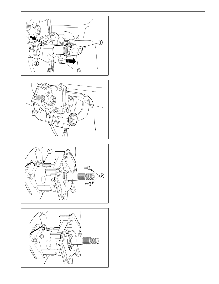
Remove the lock cylinder by pressing down the
detent spring with a 2.5MM allen wrench, or other
suitable tool, and pulling the lock cylinder out of the
switch cylinder housing (2).

D105A512

Installation Procedure

Important: To install the ignition lock cylinder the igni-
tion position should be designated I.

1. Install the ignition lock cylinder.

2. Connect the electrical connector for the immobilizer

detection coil.

3. Install the steering wheel. Refer to “Steering Wheel”

in this section.

D105A513

SWITCH HOUSING

(Left–Hand Drive Shown, Right–Hand
Drive Similar)
Removal Procedure

1. Remove the steering wheel. Refer to “Steering

Wheel” in this section.

2. Remove the turn signal switch and windshield wiper

switch. Refer to “Turn Signal Switch and Lever/Wiper
Switch and Lever” in this section.

3. Remove the switch housing.

D

Disconnect the horn electrical connector (1).

D

Remove the screws retaining the switch housing
(2).

D105A514

Installation Procedure

1. Install the switch housing with the screws.

2. Connect the horn electrical connector.

3. Install the turn signal switch and windshield wiper

switch. Refer to “Turn Signal Switch and Lever/Wiper
switch and Lever” in this section.

4. Install the steering wheel. Refer to “Steering Wheel”

in this section.

STEERING WHEEL AND COLUMN  6E – 11

D105A515

STEERING COLUMN

(Left–Hand Drive Shown, Right–Hand
Drive Similar)
Removal Procedure

1. Remove the steering wheel. Refer to “Steering Wheel”

in this section.

Caution: Disconnect the negative battery cable and
let the vehicle sit for 1 minute to deactivate the air-
bag (For vehicle with SIR)
2. Remove the turn signal switch and wiper switch. Re-

fer to “Turn Signal Switch and Lever/Wiper Switch
and Lever in this section.

3. Remove the switch housing. Refer to “Switch Hous-

ing” in this section.

D105A516

4. Remove the ignition switch. Refer to “Ignition Switch”

in this section.

5. Remove the ignition lock cylinder. Refer to “Ignition

Lock Cylinder” in this section.

6. Remove the steering column.

D

Match–mark on the intermediate shaft and the
steering column shaft (1).

D

Remove the intermediate shaft upper pinch bolt
(2).

D

Remove the steering column lower nuts (3).

D

Remove the steering column upper nuts (4).

D15A517B

D15A518B

Installation Procedure

Important: Align the match–mark on the intermediate
shaft and the steering column shaft.

1. Install the steering column.

D

Install the intermediate shaft upper pinch bolt (1).

Tighten

Tighten the pinch bolt to 21–29 N

S

m (16–22 lb-ft).

D

Install the steering column lower nuts (2).

Tighten

Tighten the nuts to 15–20 N

S

m (11–15 lb-ft).

D

Install the steering column upper nuts (3).

Tighten

Tighten the nuts to 15–20 N

S

m (11–15 lb-ft).

2. Install the ignition lock cylinder. Refer to “Ignition Lock

Cylinder” in this section.

3. Install the ignition switch. Refer to “Ignition Switch” in

this section.

4. Install the switch housing. Refer to “Switch Housing”

in this section.

5. Install the turn signal switch and wiper switch. Refer

to  “Turn Signal Switch and Lever/Wiper Switch and
Lever” in this section.

6. Install the steering wheel. Refer to “Steering Wheel”

in this section.

6E – 12  STEERING WHEEL AND COLUMN

D105A520

INTERMEDIATE SHAFT COVER AND
INTERMEDIATE SHAFT

(Left–Hand Drive Shown, Right–Hand
Drive Similar)

Removal Procedure

1. Remove the intermediate shaft.

D

In order to install the intermediate shaft correctly,
match–mark the intermediate shaft to the steering
column. (1).

D

Remove the intermediate shaft upper pinch bolt
(2).

D

Remove the intermediate shaft lower pinch bolt
(3).

D15A521A

Installation Procedure

1. Install the intermediate shaft with the bolts.

Tighten

D

Tighten the intermediate shaft lower pinch bolt to
21–29 N

S

m (16–22 lb-ft) (1).

D

Tighten the intermediate shaft upper pinch bolt to
21–29 N

S

m (16–22 lb-ft) (2).

Notice: Check the lower pinch bolt position correctly.

STEERING WHEEL AND COLUMN  6E – 13

UNIT REPAIR

D105A701

D15A702A

D15A703A

STANDARD STEERING COLUMN

Disassembly Procedure

1. Remove the steering column from the vehicle. Refer

to “Steering Column” in this section.

Caution: Be careful not to impact on the steering
column shaft. Plastic sleeve may be broken that is
installed to secure the driver at the accident.

2. Remove the steering column shaft from the steering

column.

D

Remove the retaining ring (1).

D

Remove the washer (2).

D

Remove the spring (3).

D

Remove the washer (4).

D

Remove the locking of the alignment spacer (5).

D

Push strongly the steering column shaft downward
(6).


Content   ..  182  183  184  185   ..