Daewoo Matiz (2003 year). Service manual - part 182
6E – 2 STEERING WHEEL AND COLUMN
DESCRIPTION AND OPERATION
STEERING WHEEL AND COLUMN
In addition to the steering function, the steering column
provides safety and security.
Caution: To ensure energy-absorbing action, it is
important to use only the specified screws, bolts,
and nuts, tightened to the specified torque.
The energy-absorbing column is designed to compress
in a front-end collision to lessen the chance of driver in-
jury.
The ignition switch and the lock are mounted on the col-
umn, allowing the ignition and steering operations to be
locked to inhibit theft of the car.
The column levers trigger the turn signals, the headlight
beams, and the windshield washer and wipers.
Notice: Apply a thin coat of lithium grease to all friction
points when reassembling to ensure proper operation.
The column may be easily disassembled and assembled.
D15A001A
D
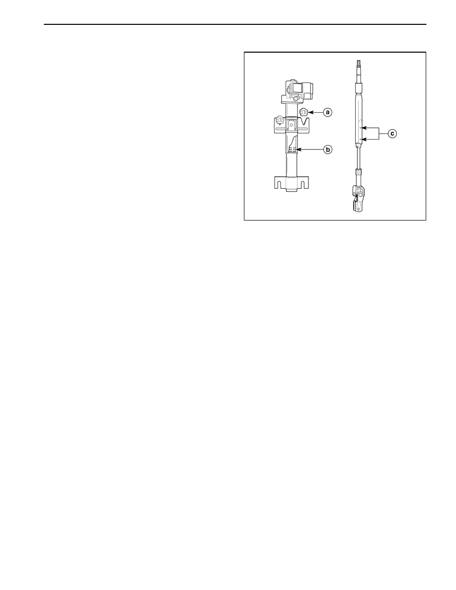
Safety Device
A. Steering Column Upper Bracket.
B. Steering Column.
C. Steering Column Shaft.