Dodge Dakota (2011 year). Instruction - part 10


  Index      Dodge     Dodge Dakota (2011 year) - instruction in english


Search            copyright infringement  


Content      ..     8      9      10      11     ..


Dodge Dakota (2011 year). Instruction - part 10


If the signal is too weak to train, replace the battery in the
handheld transmitter.

NOTE:

Some gate operators and garage door openers

may require you to replace Step 3 with procedures noted
in the “Gate Operator/Canadian Programming” section.

4. Press and hold the just-trained HomeLink

威 button. If

the indicator(s) blink rapidly for two seconds and then
remains constant, continue with the next section: “Pro-
gramming A Rolling Code System”.

NOTE:

After training a HomeLink

威 channel, if the

garage door does not operate with HomeLink

威 and the

garage door opener was manufactured after 1995, the
garage door opener may have rolling code. If so, proceed
to Step 5 “Programming A Rolling Code System.”

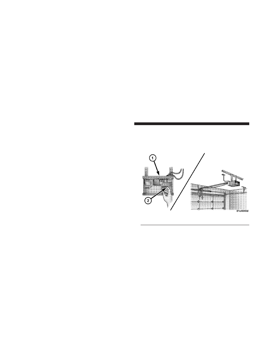
5. Programming A Rolling Code System

At the garage door opener motor (in the garage), locate
the “Learn” or “Training” button.

This can usually be found where the hanging antenna
wire is attached to the garage door opener motor (it is
NOT the button normally used to open and close the
door).

1 — Garage Door Opener
2 — Training Button

156

UNDERSTANDING THE FEATURES OF YOUR VEHICLE

6. Firmly press and release the LEARN or TRAINING
button. The name and color of the button may vary by
manufacturer.

NOTE:

You have 30 seconds in which to initiate the next

step after the LEARN button has been pressed.

7. Return to the vehicle and press the programmed
HomeLink

威 button twice (holding the button for two

seconds each time). If the device is plugged in and
activates, programming is complete.

If the device does not activate, press the button a third
time (for two seconds) to complete the training.

If you are have any problems, or require assistance,
please call toll-free 1–800–355–3515 or, on the Internet at
www.HomeLink.com for information or assistance.

To program the remaining two HomeLink

威 buttons,

repeat each step for each remaining button. DO NOT
erase the channels.

Gate Operator/Canadian Programming
Canadian radio-frequency laws require transmitter sig-
nals to “time-out” (or quit) after several seconds of
transmission – which may not be long enough for
HomeLink

威 to pick up the signal during programming.

Similar to this Canadian law, some U.S. gate operators are
designed to “time-out” in the same manner.

It may be helpful to unplug the device during the cycling
process to prevent possible overheating of the garage
door or gate motor.
If you are having difficulties programming a garage door
opener or a gate operator, replace “Programming
HomeLink,” Step 3, with the following:
3. Continue to press and hold the HomeLink

威 button,

while you press and release (“cycle”), your handheld
transmitter every two seconds until HomeLink

威 has

successfully accepted the frequency signal. The indica-
tor(s) will change from a slow flash to a rapid flash
when trained.

3

UNDERSTANDING THE FEATURES OF YOUR VEHICLE

157

If you unplugged the device for training, plug it back in
at this time.

Then proceed with Step 4 under, “Programming
HomeLink

威,” earlier in this section.

Using HomeLink

To operate, press and release the programmed
HomeLink

威 button. Activation will now occur for the

trained device (i.e., garage door opener, gate operator,
security system, entry door lock, home/office lighting,
etc.,). The handheld transmitter of the device may also be
used at any time.

Reprogramming A Single HomeLink

姞 Button

To reprogram a channel that has been previously trained,
follow these steps:

1. Turn the ignition switch to the ON/RUN position.

2. Press and hold the desired HomeLink

威 button for

20 seconds until the indicator(s) starts to flash. Do not
release the button.

3. Without releasing the button, proceed with Program-
ming HomeLink

威, Step #2, and follow all remaining

steps.

Security
It is advised to erase all channels before you sell or turn
in your vehicle.

To do this, press and hold the two outside buttons for
20 seconds until the indicators begin to flash. Note that
all channels will be erased. Individual channels cannot be
erased.

The HomeLink

威 Universal Transceiver is disabled when

the Vehicle Theft Alarm is active.

158

UNDERSTANDING THE FEATURES OF YOUR VEHICLE

Troubleshooting Tips
If you are having trouble programming HomeLink

威, here

are some of the most common solutions:

• Replace the battery in the original transmitter.
• Press the LEARN button on the garage door opener to

complete the training for Rolling Code.

• Did you unplug the device for training and remember

to plug it back in?

If you have any problems, or require assistance, please
call toll-free 1–800–355–3515 or, on the Internet at
www.HomeLink.com, for information or assistance.

General Information
This device complies with FCC rules part 15 and Industry
Canada RSS-210. Operation is subject to the following
two conditions:

1. This device may not cause harmful interference.

2. This device must accept any interference that may be
received including interference that may cause undesired
operation.

NOTE:

The transmitter has been tested and it complies

with FCC and IC rules. Changes or modifications not
expressly approved by the party responsible for compli-
ance could void the user’s authority to operate the
device.

The term “IC” before the certification/registration num-
ber only signifies that Industry Canada technical specifi-
cations were met.

3

UNDERSTANDING THE FEATURES OF YOUR VEHICLE

159

ELECTRICAL POWER OUTLETS
This vehicle has two 12 Volt (13 Amp) auxiliary power
outlets that can provide power for accessories designed
for use with standard power outlet adapters. One power
outlet is located in the instrument panel (below the
temperature control setting knob) and one is located
inside the full-size center console.

When the optional Cigar Lighter heating element is used,
it heats when pushed in and pops out automatically
when ready for use. To preserve the heating element, do
not hold the lighter in the heating position.

NOTE:

To ensure proper operation a MOPAR

威 knob

and element must be used.

CAUTION!

• Do not exceed the maximum power of 160 Watts

(13 Amps) at 12 Volts. If the 160 Watt (13 Amp)
power rating is exceeded the fuse protecting the
system will need to be replaced.

• Power outlets are designed for accessory plugs

only. Do not insert any other object in the power
outlets as this will damage the outlet and blow the
fuse. Improper use of the power outlet can cause
damage not covered by your warranty.

Instrument Panel Outlet

160

UNDERSTANDING THE FEATURES OF YOUR VEHICLE

WARNING!

To avoid serious injury or death:
• Only devices designed for use in this type of

outlet should be inserted into any 12 Volt outlet.

• Do not touch with wet hands.

• Close the lid when not in use and while driving

the vehicle.

• If this outlet is mishandled, it may cause an

electric shock and failure.

Power Outlet Fuse Locations

1 — #22 Fuse 20 A Yellow Cigar Lighter Front Console
2 — #28 Fuse 20 A Yellow Power Outlet Center Console

3

UNDERSTANDING THE FEATURES OF YOUR VEHICLE

161

CAUTION!

• Many accessories that can be plugged in, draw

power from the vehicle’s battery, even when not in
use (i.e., cellular phones, etc.). Eventually, if
plugged in long enough, the vehicle’s battery will
discharge sufficiently to degrade battery life
and/or prevent the engine from starting.

• Accessories that draw higher power (i.e., coolers,

vacuum cleaners, lights, etc.), will discharge the
battery even more quickly. Use these only inter-
mittently and with greater caution.

• After the use of high power draw accessories, or

long periods of the vehicle not being started (with
accessories still plugged in), the vehicle must be
driven a sufficient length of time to allow the
generator to recharge the vehicle’s battery.

CUPHOLDERS
If your vehicle has bucket seats with a center console,
there are three cupholders located on the console.

A two-cavity cupholder is available on all Crew Cabs,
with rear seats mounted on the floor.

Front Cup Holders — Crew Cab

162

UNDERSTANDING THE FEATURES OF YOUR VEHICLE

REAR CRATE ’N GO

姞 STORAGE — IF EQUIPPED

The rear Crate ’n Go

威 storage, located under the rear seat

lower cushion, consists of two removable, collapsible
storage crates.

To open the crates, lift upward on the crate handles and
engage the crate end flaps.

Rear Cup Holders — Crew Cab

Open Crate

1 — Crate Handles
2 — Crate End Flaps
3 — Release Lever

3

UNDERSTANDING THE FEATURES OF YOUR VEHICLE

163

To remove the crate, press on the release lever, located on
the ends of the base, and lift up on the crate.

To install the crate into the base, insert the crate into the
inboard slot and push down on the outboard side of the
crate, then snap into place.

To collapse the crate, push the crate end flaps inward to
disengage. Push the sides inward and snap into place.

WARNING!

Do not sit or stand on this crate. It may collapse
causing serious injury.

CAUTION!

Do not lift up on the “End Flaps” to open the crate,
damage to the “End Flaps” may occur.

NOTE:

The maximum loading capacity for the small

crate is 30 lbs (13.6 kg) and 50 lbs (22.6 kg) for the large
crate.

Insert Crate

164

UNDERSTANDING THE FEATURES OF YOUR VEHICLE

Plastic Grocery Bag Retainers
Retainer hooks, which will hold plastic grocery bag
handles, are built into the back panel of the cab.

CONSOLE FEATURES — IF EQUIPPED

Floor Console Features
The Floor Console between the driver’s and front pas-
senger’s seat has the following features:

• Miscellaneous storage compartments.
• Three cupholders (two removable).
• iPod/Phone storage bin.
• 12 Volt power outlet inside storage compartment.
• Side open armrest lid.
• Tissue holder and two pen holders.

Grocery Bag Retainers

3

UNDERSTANDING THE FEATURES OF YOUR VEHICLE

165

• Coin slots (located under the instrument panel center

stack).

WARNING!

Do not operate this vehicle with a console compart-
ment lid in the open position. Cellular phones, music
players, and other handheld electronic devices
should be stowed while driving. Use of these devices
while driving can cause an accident due to distrac-
tion, resulting in death or injury.

Storage Compartments
Some miscellaneous storage compartments and cuphold-
ers are both removable and dishwasher safe (upper rack
of dishwasher only) for cleaning purposes. Various stor-
age compartments provide versatile and useful storage.
A coin holder is also provided inside the driver side
storage bin.

Floor Console

166

UNDERSTANDING THE FEATURES OF YOUR VEHICLE

Power Outlet And Portable Phone Storage
The console is equipped with a power outlet and an
iPod/phone storage bin. The phone storage bin can be
used when easy access to the phone is needed. Also, the
power outlet inside the console compartment can be used
to charge the phone while it is being stored in the bin. The
power outlet may be used for any portable item with a
standard 12 Volt power plug.

Side Open Armrest Lid
Pressing the button on the left side of the console opens
the console armrest lid. The armrest lid will remain open
until the armrest lid is closed instructionly, by pressing the
lid back into place. Two pen holders are provided on the
inside of the armrest lid. A tissue holder is also provided
on the inside of the armrest lid, which holds a pocket-size
soft pack of tissue.

CARGO AREA FEATURES

Rear Cargo Area Utility Rails — If Equipped

CAUTION!

The maximum load per cleat should not exceed
320 lbs (145 kg) and the angle of the load on each
cleat should not exceed 60 degrees above horizontal,
or damage to the cleat or cleat rail may occur.

There are four adjustable cleats that can be used to assist
in securing cargo. Each cleat must be located and tight-
ened down in one of the detent’s, along either rail, in
order to keep cargo properly secure.

3

UNDERSTANDING THE FEATURES OF YOUR VEHICLE

167

To move the cleat to any position on the rail, turn the nut
counterclockwise, approximately three turns. Then pull
out on the cleat and slide it to the detent nearest the
desired location. Make sure the cleat is seated in the
detent and tighten the nut.

To remove the cleats from the utility rail, remove the end
cap by pushing up on the locking tab, located on the
bottom of the end cap. Slide the cleat off the end of the
rail.

1 — Utility Rail Detent’s
2 — Utility Rail Cleat
3 — Cleat Retainer Nut

Utility Rail End Cap

168

UNDERSTANDING THE FEATURES OF YOUR VEHICLE

REAR WINDOW FEATURES

Rear Window Defroster — If Equipped

The rear window defroster button is located on the
right-side of the Air Conditioning and Heater

Control, below the A/C (snowflake) button. Press this
button to turn on the rear window defroster and the
heated outside mirrors (if equipped). An indicator in the
button will illuminate when the rear window defroster is
on. The rear window defroster automatically turns off
after approximately 10 minutes. For an additional five
minutes of operation, press the button a second time.

NOTE:

To prevent excessive battery drain, use the rear

window defroster only when the engine is operating.

CAUTION!

Failure to follow these cautions can cause damage to
the heating elements:
• Use care when washing the inside of the rear

window. Do not use abrasive window cleaners on
the interior surface of the window. Use a soft cloth
and a mild washing solution, wiping parallel to
the heating elements. Labels can be peeled off
after soaking with warm water.

• Do not use scrapers, sharp instruments, or abra-

sive window cleaners on the interior surface of the
window.

• Keep all objects a safe distance from the window.

3

UNDERSTANDING THE FEATURES OF YOUR VEHICLE

169

Sliding Rear Window — If Equipped
A locking device in the center of the window helps to
prevent entry from the rear of the vehicle. Squeeze the
lock to release the window.

SLIDE-IN CAMPERS

Camper Applications
Certain truck models are not recommended for slide-in
campers. To determine if your vehicle is excluded, please
refer to the Consumer Information Truck-Camper Load-
ing document, located in your Owner’s Instruction packet or
available from your authorized dealer. For safety reasons,
follow all instructions on this important document.

General Information
The Manufacturer’s Warranty does not apply to body
modifications and special equipment, such as a camper
unit, heaters, stoves, refrigerators, etc., supplied by
manufacturers other than Chrysler Group LLC. For war-
ranty coverage and service on these items, contact the
applicable manufacturer.

Sliding Rear Window Latch

170

UNDERSTANDING THE FEATURES OF YOUR VEHICLE

To mount a camper unit with an overhang, the tailgate
can be removed. Unlatch the tailgate and remove the
support cables from the retainer pins. Raise the right side
of the tailgate until the lower right side pivot clears the
hanger bracket. Then slide the tailgate to the right to
remove.

Carbon Monoxide Warning-Vehicles Equipped
With A Cap Or Slide-In Campers
To avoid inhaling carbon monoxide, which is deadly, the
exhaust system on vehicles equipped with “Cap Or
Slide-In Campers” should extend beyond the overhang-
ing camper compartment and be free of leaks.

TAILGATE

Tailgate Removal
To simplify mounting a camper unit with an overhang,
the tailgate can be removed quickly. Follow these steps:

1. Open the tailgate to a 45 degree angle.

2. Unclip and remove the cables from the box while
maintaining a 45 degree angle.

3. Lift the tailgate off of the pivot on the passenger side
by pulling upward and rearward at the same time.

4. Slide the tailgate to the passenger side while making
sure clearance from the box and taillight is maintained.

To reinstall the tailgate, do the following:

1. Slide the tailgate onto the driver’s side pivot.

2. Hold the tailgate at a 45 degree angle and insert it into
the passenger side pivot.

3. Clip the cables to the box.

3

UNDERSTANDING THE FEATURES OF YOUR VEHICLE

171


Content      ..     8      9      10      11     ..