Dodge 5500 Chassis Cab (2008 year). Instruction - part 8


  Index      Dodge     Dodge 5500 Chassis Cab (2008 year) - instruction in english


Search            copyright infringement  


Content      ..     6      7      8      9     ..


Dodge 5500 Chassis Cab (2008 year). Instruction - part 8


WARNING!

Persons who are unable to feel pain to the skin
because of advanced age, chronic illness, diabetes,
spinal cord injury, medication, alcohol use, exhaus-
tion or other physical condition must exercise care
when using the seat heater. It may cause burns even
at low temperatures, especially if used for long
periods of time.

Do not place anything on the seat that insulates
against heat, such as a blanket or cushion. This may
cause the seat heater to overheat.

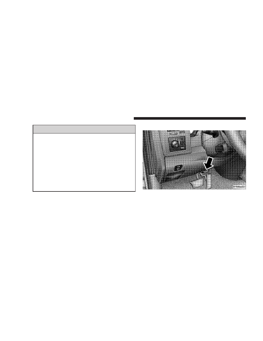
TO OPEN AND CLOSE THE HOOD

To open the hood, two latches must be released. First pull
the hood release lever located below the steering wheel at
the base of the instrument panel. Once the hood is
released you must reach into the opening beneath the
center of the grille and push up the latch to release the
safety catch before raising the hood.

Hood Release Lever

120

UNDERSTANDING THE FEATURES OF YOUR VEHICLE

To prevent possible damage, do not slam the hood to
close it. Use a firm downward push at the front center of
the hood to ensure that both latches engage.

WARNING!

If the hood is not fully latched, it could fly up when
the vehicle is moving and block your forward vision.
Be sure all hood latches are latched fully before
driving.

Secondary Latch

UNDERSTANDING THE FEATURES OF YOUR VEHICLE

121

3

LIGHTS

Interior Lights

Courtesy and dome lights are turned on when the front
doors are opened, when the dimmer control (rotating
wheel on the right side of the switch) is rotated to the
upward detent position, or if equipped, when the UN-
LOCK button is pressed on the key fob. When a door is

Headlight Switch Location

Dimmer Control

122

UNDERSTANDING THE FEATURES OF YOUR VEHICLE

open and the interior lights are on, rotating the dimmer
control all the way down to the OFF detent will cause all
the interior lights to go out. This is also known as the

9Party9 mode because it allows the doors to stay open for
extended periods of time without discharging the vehi-
cle’s battery.

The brightness of the instrument panel lighting can be
regulated by rotating the dimmer control up (brighter) or
down (dimmer). When the headlights are ON you can
supplement the brightness of the odometer, trip odom-
eter, radio and overhead console by rotating the control
up until you hear a click. This feature is termed the
“Parade” mode and is useful when headlights are re-
quired during the day.

Club Cab/Quad Cab models may have an optional
switched dome lamp that may be operated by pressing
the lens.

Battery Saver

To protect the life of your vehicle’s battery, Load Shed-
ding is provided for both the interior and exterior lights.

If the ignition is off and any door is left ajar for 10
minutes or the dimmer control is rotated upwards for 10
minutes, the interior lights will automatically turn off.

If the headlamps remain on while the ignition is cycled
off, the exterior lights will automatically turn off after 8
minutes. If the headlamps are turned on and left on for 8
minutes while the ignition is off, the exterior lights will
automatically turn off.

NOTE:

Battery Saver mode is cancelled if the ignition is

ON.

UNDERSTANDING THE FEATURES OF YOUR VEHICLE

123

3

Headlamp Delay

To aid in your exit, your vehicle is equipped with a
headlamp delay that will leave the headlamps on for 90
seconds. This delay is initiated when the ignition is
turned OFF while the headlamp switch is on, and then
the headlamp switch is cycled off. Headlamp delay can
be cancelled by either turning the headlamp switch ON
then OFF or by turning the ignition ON.

The Headlight delay time is programmable on vehicles
equipped with the Electronic Vehicle Information Center
(EVIC). For details, refer to “Headlamp Off Delay”,
under “Personal Settings (Customer Programmable Fea-
tures),” under “Electronic Vehicle Information Center
(EVIC)” in Section 3 of this instruction.

Headlights, Parking Lights, Panel Lights

When the headlight switch is rotated to the first
position, the parking lights, taillights, side marker
lights, license plate light and instrument panel

lights are all turned on. The headlights will turn ON
when the switch is rotated to the second position.

Light Switch Rotation

124

UNDERSTANDING THE FEATURES OF YOUR VEHICLE

Your vehicle is equipped with plastic headlight lenses
that are lighter and less susceptible to stone breakage
than glass headlights.

Plastic is not as scratch resistant as glass and therefore
different lens cleaning procedures must be followed.

To minimize the possibility of scratching the lenses and
reducing light output, avoid wiping with a dry cloth. To
remove road dirt, wash with a mild soap solution fol-
lowed by rinsing.

Do not use abrasive cleaning components, solvents, steel
wool or other abrasive materials to clean the lenses.

Daytime Running Lights (Canada Only and Fleet
Vehicles)

The headlights on your vehicle will illuminate when the
engine is started and the transmission is in any gear

except park. This provides a constant

9Lights ON9 con-

dition until the ignition is turned OFF. The lights illumi-
nate at less than 50% of normal intensity. If the parking
brake is applied the Daytime Running Lights will turn
off. Also, if a turn signal is activated, the DRL lamp on the
same side of the vehicle will turn off for the duration of
the turn signal activation. Once the turn signal is no
longer active, the DRL lamp will illuminate

Lights-on Reminder

If the headlights, parking lights, or cargo lights are left
on, after the ignition is turned off, a chime will sound
when the driver’s door is opened.

Fog Lights — If Equipped

The foglights are turned ON by placing the head-
light rotary control in the parking light or head-
light position and pushing in the headlight rotary

control. The fog lights will operate only when the parking
lights are ON or when the vehicle headlights are ON low

UNDERSTANDING THE FEATURES OF YOUR VEHICLE

125

3

beam. An indicator light located in the instrument cluster
will illuminate when the fog lights are on. The fog lights
will turn off when the switch is pushed a second time,
when the headlight switch is rotated to the OFF position,
or the high beam is selected.

Multifunction Control Lever

The multifunction control lever is located on the left side
of the steering column.

Turn Signals
Move the lever up or down to signal a right-hand or
left-hand turn.

The arrow on either side of the instrument cluster flashes
to indicate the direction of the turn, and proper operation
of the front and rear turn signal lights. If a defective bulb
or wiring circuit is detected for the turn signal system, the
arrow indicators will flash at a faster rate. If an indicator
fails to light when the lever is moved, it would suggest
that the switch or indicator lamp is defective.

You can signal a lane change by moving the lever
partially up or down.

Turn Signal Auto-Mode
Tap the multi-function control lever once and the turn
signal (left or right) will flash 3 times, and automatically
turn off.

Turn Signal Lever

126

UNDERSTANDING THE FEATURES OF YOUR VEHICLE

Passing Light
You can signal another vehicle with your headlights by
partially pulling the multifunction lever toward the steer-
ing wheel. This will cause the high beam headlights to
turn on until the lever is released.

High Beam / Low Beam Select Switch
Pull the multifunction control lever fully toward the
steering wheel to switch the headlights from HIGH or
LOW beam.

High Beam / Low Beam

UNDERSTANDING THE FEATURES OF YOUR VEHICLE

127

3

WINDSHIELD WIPERS AND WASHERS

Windshield Wipers

The wipers and washers are operated by a switch in the
multifunction control lever. Turn the end of the handle to
select the desired wiper speed.

Intermittent Wiper System
The intermittent feature of this system was designed for
use when weather conditions make a single wiping cycle,
with a variable pause between cycles, desirable. For
maximum delay between cycles, rotate the control knob
into the upper end of the delay range.

The delay interval decreases as you rotate the knob until
it enters the LOW continual speed position. The delay
can be regulated from a maximum of about 15 seconds
between cycles, to a cycle every 2 seconds. The delay
intervals will double in duration when the vehicle speed
is 10 mph (16 km) or less.

Windshield Wiper / Washer Switch

128

UNDERSTANDING THE FEATURES OF YOUR VEHICLE

WARNING!

Sudden loss of visibility through the windshield
could lead to an accident. You might not see other
vehicles or other obstacles. To avoid sudden icing of
the windshield during freezing weather, warm the
windshield with defroster before and during wind-
shield washer use.

Windshield Washers

To use the washer, push in on the washer knob on the end
of the multifunction control lever and hold while spray is
desired. If the washer knob is depressed while in the
delay range, the wiper will operate for several seconds
after the washer knob is released. It will then resume the
intermittent interval previously selected. If the washer
knob is pushed, for a period greater than 1 second, while
in the OFF position, the wiper will wipe approximately
three wipes, after the wash knob is released.

To prevent freeze-up of your windshield washer system
in cold weather, select a solution or mixture that meets or
exceeds the temperature range of your climate. This
rating information can be found on most washer fluid
containers.

UNDERSTANDING THE FEATURES OF YOUR VEHICLE

129

3

TILT STEERING COLUMN

To tilt the column, pull rearward on the lever below the
turn signal control and move the wheel up or down, as
desired. Push the lever forward to lock the column firmly
in place.

WARNING!

Tilting the steering column while the vehicle is
moving is dangerous. Without a stable steering col-
umn, you could lose control of the vehicle and have
an accident. Adjust the column only while the ve-
hicle is stopped. Be sure it is locked before driving.

Tilt Steering Control Lever

130

UNDERSTANDING THE FEATURES OF YOUR VEHICLE

DRIVER ADJUSTABLE PEDALS — IF EQUIPPED

The power adjustable accelerator and brake pedals allow
the driver to establish a comfortable position relative to
the steering wheel and pedals.

Adjustment

1. Position the driver seat so that you are at least 10
inches (254 mm) away from the airbag located in the
center of the steering wheel.

2. Fasten and adjust the seatbelts.

3. Move the adjustable pedal switch, located to the left of
the steering column near the parking brake release, in the
direction you desire to move the pedals.

4. The pedals cannot be adjusted when the vehicle is in
R (Reverse) or when the Speed Control is SET.

Adjustable Pedals Switch

UNDERSTANDING THE FEATURES OF YOUR VEHICLE

131

3

CAUTION!

Do not place any article under the adjustable pedals
or impede its ability to move as it may cause damage
to the pedal controls. Pedal travel may become lim-
ited if movement is stopped by an obstruction in the
adjustable pedal’s path.

ELECTRONIC SPEED CONTROL — IF EQUIPPED

When engaged, this device takes over accelerator opera-
tion at speeds greater than 35 mph (56 km/h). The
controls are mounted on the steering wheel.

NOTE:

The Electronic Speed Control System has been

designed to shut down if multiple speed control switch
buttons (i.e. SET and CANCEL) are operated simulta-
neously in order to ensure proper operation. The system
can be reactivated by pushing the speed control switch
ON/OFF button and re-establishing the desired vehicle
SET speed.

132

UNDERSTANDING THE FEATURES OF YOUR VEHICLE

To Activate

Push the ON/OFF button to the ON position. An indi-
cator light in the instrument cluster illuminates when the
system is on.

To Set At A Desired Speed

When the vehicle has reached the desired speed, press
and release the SET button. Release the accelerator and
the vehicle will operate at the selected speed.

To Deactivate

A soft tap on the brake pedal, normal braking, clutch
pressure while slowing the vehicle, or pressing the CAN-
CEL button will deactivate speed control without erasing
the memory. Pushing the ON/OFF button to the OFF
position or turning off the ignition erases the memory.

WARNING!

Leaving the Speed Control ON when not in use is
dangerous. You could accidentally set the system to
cause it to go faster than you want. You could lose
control and have an accident. Always leave the sys-
tem OFF when you aren’t using it.

To Resume Speed

To resume a previously set speed, push and release the
RESUME button. Resume can be used at any speed above
30 mph (50 km/h).

To Vary The Speed Setting

When the speed control is on, speed can be increased by
pressing and holding the ACCEL button. When the
button is released, a new set speed will be established.

UNDERSTANDING THE FEATURES OF YOUR VEHICLE

133

3

Tapping the ACCEL button once will result in a 2 mph
(3km/h) speed increase. Each time the button is tapped,
speed increases so that tapping the button three times
will increase speed by 6 mph (10 km/h), etc.

Tapping the DECEL button once will result in a 1 mph (2
km/h) speed decrease. Each time the button is tapped,
speed will decrease. For example, tapping the button 3
times will decrease the speed by 3 mph (5 km/h), etc.

To decrease speed while the speed control is on, press
and hold the DECEL button. Release the button when the
desired speed is reached, and the new speed will be set.

To Accelerate For Passing

Depress the accelerator as you would normally. When the
pedal is released, the vehicle will return to the set speed.

NOTE:

When driving uphill, at elevations above 2,000

ft. (610 meters), or when the vehicle is heavily loaded
(especially when towing) the vehicle may slow below the

SET speed. If the vehicle speed drops below 35 mph (56
km/h), the speed control will automatically disengage. If
this happens, you can push down on the accelerator
pedal to maintain the desired speed.

Vehicles equipped with a 6–speed instruction transmission
should be operated in 4th or 5th gear under the above
conditions.

WARNING!

Speed Control can be dangerous where the system
can’t maintain a constant speed. Your vehicle could
go too fast for the conditions, and you could lose
control. An accident could be the result. Don’t use
Speed Control in heavy traffic or on roads that are
winding, icy, snow-covered, or slippery.

134

UNDERSTANDING THE FEATURES OF YOUR VEHICLE

OVERHEAD CONSOLE WITH
COMPASS/TEMPERATURE MINI-TRIP COMPUTER
— IF EQUIPPED

This optional overhead console consists of the following:

• Courtesy Lights
• Compass/Temperature Mini-Trip Computer (CMTC)

This overhead console allows you to choose between a
compass/temperature display and one of four trip con-
ditions being monitored.

US/M Button

Use this button to change the display from U.S. to metric
measurement units.

UNDERSTANDING THE FEATURES OF YOUR VEHICLE

135

3


Content      ..     6      7      8      9     ..