Haima M3. A/C, Restraint System, Body Accessories, Electrical System. Instruction - part 6


  Index      Haima     Haima M3. A/C, Restraint System, Body Accessories, Electrical System. Instruction


Search            copyright infringement  


Content      ..     4      5      6      7     ..


Haima M3. A/C, Restraint System, Body Accessories, Electrical System. Instruction - part 6


Body and Accessories 3C-33 


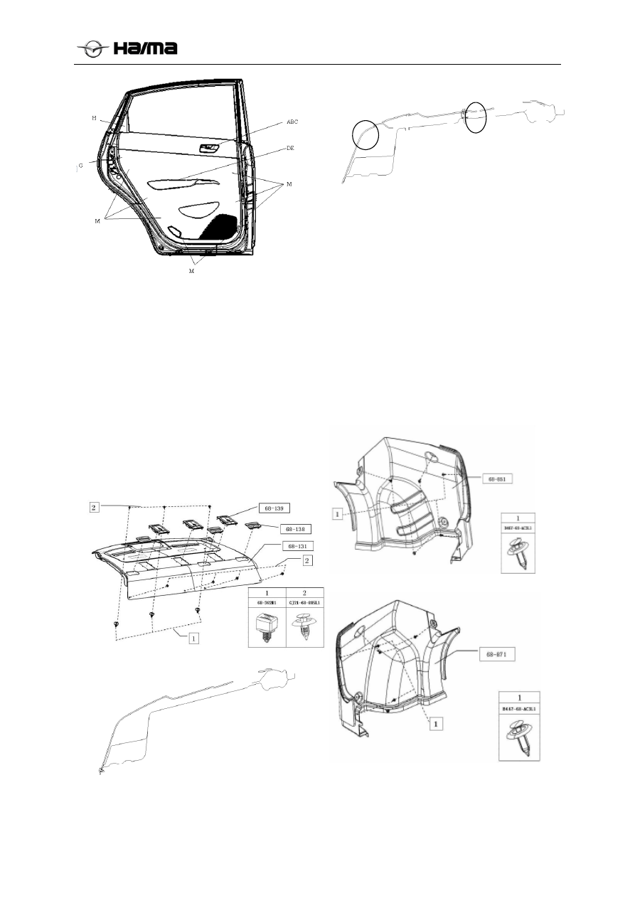
Removal/Installation of Interior Rear 
Parcel Shelf 

1.  Disconnect the negative cable of the battery. 

2.  Remove the rear doorsill. (Refer to Removal/ 

Installation of Doorsills of Four Doors) 

3.  Remove the door opening weatherstrips. 

(Refer to the Removal/ Installation of Door 
Opening Weatherstrip) 

4.  Remove the rear wheel cover trim plate. 

(Refer to Removal/ Installation of Rear Wheel 
Cover Trim Plate, Trimming) 

5.  Remove the left and right C-pillar trim plates 

(Refer to Removal/Installation of C-Pillar 
Trim Plate) 


6.  Loosen 7 clips (4 lower clips and 3 upper 

clips) from the position ② of the body. 


7.  Remove the patch cord behind the high-

mounted brake lamp and then the rear parcel 
shelf.  

Perform the installation in reverse order of the 
removal. 

Removal/Installation of Side Trim Plates 
of the Trunk 

1.  Remove the trunk mat and the foam toolbox.  

2.  Remove the rear trim plate of the trunk. 

(Refer to the Removal/Installation of Rear 
Trim Plate of the Trunk) 

3.  Remove the snap fasteners. (5 in total in the 

figure) 


Right side 


Left side 


-------------------------------------------------------------------------------------------------------------------------------------------------------------


Body and Accessories 3C-34 


4.  Pull and remove the side trim plates of the 

trunk.  

5.  Perform the installation in reverse order of the 

removal. 

Removal/Installation of Trunk Lid Trim 
Plate 

Use a fastening screw puller to pull the clip ① 
from the body. 


Ceiling  


Removal/Installation of Ceiling 

1.  Disconnect the negative cable of the battery. 

2.  Remove doorsills of four doors. (Refer to the 

Removal/Installation of Doorsills of Four 
Doors) 

3.  Remove the door opening weatherstrips. 

(Refer to the Removal/Installation of Door 
Opening Weatherstrip) 

4.  Remove the A-pillar trim plate. ( Refer to the 

Removal/Installation of A-Pillar Trim Plate, 
Trimming) 

5.  Remove the B-pillar lower trim plate. (Refer 

to the Removal/Installation of B-Pillar Lower 
Trim Plate, Trimming) 

6.  Remove the B-pillar upper trim plate . (Refer 

to the Removal/Installation of B-Pillar Upper 
Trim Plate, Trimming) 

7.  Remove the rear wheel cover trim plate. 

(Refer to Removal/Installation of Rear Wheel 
Cover Trim Plate, Trimming) 

8.  Remove the C-pillar trim plate. (Refer to the 

Removal/Installation of C-Pillar Trim Plate, 
Trimming) 

9.  Remove the interior lamp. (Refer to the 

Removal/Installation of Interior Lamp, 
Interior Lighting System, Electrical Section) 

10.  Remove screws and then the sun visor, the 

sun visor mount and the auxiliary handle.  

11.  If the vehicle is equipped with a sunroof, 

please remove the sunroof trim strip at first 
(by using the method same as that of 
removing and installing the door opening 
weatherstrips). 

12. 

Remove the front seats. (Refer to 
Removal/Installation of Front Seats, Seats) 

-------------------------------------------------------------------------------------------------------------------------------------------------------------


Body and Accessories 3C-35 


13.  Remove the rear seat cushion. (Refer to the 

Removal/Installation of Front Seats, Seats) 

14.  Remove the clips and take out the ceiling. 

Without sunroof 


With sunroof 


Floor Coverings 

Removal/Installation of Floor Coverings 

1.  Disconnect the negative cable of the battery. 

2.  Remove doorsills of four doors. (Refer to the 

Removal/Installation of Doorsills of Four 
Doors) 

3.  Remove the door opening weatherstrips. 

(Refer to the Removal/Installation of Door 
Opening Weatherstrip) 

4.  Remove the mounting bolt from the lower 

anchorage point of the front seat belt.  

5.  Remove the B-pillar lower trim plate. (Refer 

to the Removal/Installation of B-Pillar Lower 
Trim Plate, Trimming) 

6.  Remove the A-pillar lower trim plate. (Refer 

to the Removal/Installation of A-Pillar Lower 
Trim Plate, Trimming) 

7.  Remove the rear wheel cover trim plate. 

(Refer to Removal/Installation of Rear Wheel 
Cover Trim Plate, Trimming) 

8.  Remove the front seats. (Refer to the 

Removal/Installation of Front Seats, Seats) 

9.  Remove the rear seat cushion. (Refer to 

Removal/Installation of Rear Seats, Seats) 

10.  Remove the auxiliary fascia console. (Refer to 

the Removal/Installation of Auxiliary Fascia 
Console, Instrument Panel and Control Panel) 

Remove clips, harness clips, filler cover plate, and 
then remove the floor coverings.  


1.  Take out the floor coverings from the front 

passenger door.  

2.  Perform the installation in reverse order of the 

removal. 

Seats 

Removal/Installation of Front Seats 

With side airbags 

Warning: 

  Improperly handling the front seat may 

trigger the side airbag unexpectedly, resulting 
in personal injury; therefore, please read the 
maintenance warning carefully before 
handling it. (Refer to  the Maintenance 
Warning, Airbag System, Section T) 

Turn the ignition switch to the LOCK position. 

Disconnect the negative cable of the battery and 

wait for over 1min to have the standby power 
exhausted.  

Perform the removal in the order shown in the 
following table.  

Perform the installation in reverse order of the 
removal. 


-------------------------------------------------------------------------------------------------------------------------------------------------------------


Body and Accessories 3C-36 


Side airbag module connector  
(Refer to the Removal Instruction) 
(Refer to the Installation Instruction) 

Seat belt buckle switch connector 
(Refer to the Installation Instruction) 

SBR switch connector (only for the front
passenger seat) 

4 Front 

seat 

Removal instruction for side airbag 
module connector 

  Remove the connector from the seat cushion 

frame and then disconnect the side airbag 
module connector. 

Installation instruction for side airbag 
module connector 

1.  Before connecting the side airbag harness 

connector, please confirm the side airbag 
module harness connector at the vehicle side 
passes below the mobile cable.  


2.  Fix them on the cushion frame after the 

connectors are connected.  

Installation instruction for seat belt buckle switch 
connector 

  Before connecting with the seat belt buckle 

switch connector (the vehicle harness 
connector), please confirm the seat belt 
buckle switch harness connector do pass 
below the mobile cable.  


Installation instruction for SBR switch connector 


Before connecting with the SBR buckle 
switch connector (the vehicle harness 
connector), please confirm the SBR switch 
harness connector do pass below the mobile 
cable. 


Without side airbags 

Disconnect the negative cable of the battery. 

Perform the removal in the order shown in the 
following table. 

Perform the installation in reverse order of the 
removal. 


1

Seat belt buckle switch connector (only for the 
driver side) 

(Refer to the Installation Instruction)


3

Front seat


Installation instruction for seat belt buckle switch 
connector 


Before connecting with the seat belt buckle 
switch connector (the vehicle harness 
connector), please confirm the seat belt 
buckle switch harness connector do pass 
below the mobile cable. 

Side airbag module 
harness connector 

Side airbag module 
connector 

Mobile cable 

Seat belt buckle switch connector

Mobile cable

Mobile cable

SBR switch connector 

-------------------------------------------------------------------------------------------------------------------------------------------------------------


Body and Accessories 3C-37 


Seat belt buckle switch connector

Mobile cable 

-------------------------------------------------------------------------------------------------------------------------------------------------------------


Body and Accessories 3C-38 


Disassembly/Assembly of Driver Seat (Without Side Airbag) 

Perform the disassembly in the order shown in the table. 

Perform the assembly in reverse order of the disassembly. 


1


Headrest


9


Seat back


2


1# guide rod (FR)


 10


Seat back frame


3


2# guide rod (FR)


 11


4


Recliner handle


 12


5


4# front side protective cover


 13


6


Front seat belt buckle


 14


7


Front seat cushion


 15


8


Cushion base plate


 16


-------------------------------------------------------------------------------------------------------------------------------------------------------------


Body and Accessories 3C-39 


Disassembly/Assembly of Driver Seat (With Side Airbag) 

Warning: 

  Improperly handling the front seat may trigger the side airbag unexpectedly, resulting in 

personal injury; therefore, please read the maintenance warning carefully before handling it. 
(Refer to  the Maintenance Warning, Airbag System, Section T) 


1


Headrest


9


Outer cover, driver seat (right)


2


1# guide rod (FR)


 10


Seat back frame


3


2# guide rod (FR)


 11


Side airbag


4


Recliner handle


 12


Seat back frame


5


Trim cover, height adjustment 
handle


 13


front seats cushion (left)


6


Height adjustment handle


 14


Inner cover, driver seat (left)


7


Outer cover, recliner (left)


15


Inner cover, driver seat (right)


8


Front seat belt buckle


16


Seat frame


-------------------------------------------------------------------------------------------------------------------------------------------------------------


Body and Accessories 3C-35 


Removal/Installation of Rear Seat 

Perform the removal in the order shown in the 
table. 

Perform the installation in reverse order of the 
removal. 


1


Rear seat cushion


2


Rear seat back


Disassembly/Assembly of Rear Seat 

1.  Perform the disassembly in the order shown in 

the table. 

2.  Perform the assembly in reverse order of the 

disassembly. 


1


Rear seat cushion


2


Rear seat back


Removal/Installation of Rear Seat 

Perform the removal in the order shown in the 
table. 

Perform the installation in reverse order of the 
removal. 


1


Rear seat cushion


2


Rear seat back (left)


2


Rear seat back(right)


-------------------------------------------------------------------------------------------------------------------------------------------------------------


Body and Accessories 3C-36 


Disassembly/Assembly of Rear Seat 

3.  Perform the disassembly in the order shown in the table.  

Perform the assembly in reverse order of the disassembly. 


1


Headrest


 11

Rear seat back (right)


2


1# guide rod (FR)


 12

Rear seat back frame assembly (right)


3


2# guide rod (FR)


 13

Rear seat back hinge (right)


4


Seat back unlock button (left)


 14

Rear seat intermediate armrest


5


Seat back unlock trim cover (left)


 15

Intermediate armrest plate


6


Seat cushion


 16

Rear seat back central hinge


7


Seat cushion turnover mechanism


8


Rear seat back (left)


9


Rear seat back frame assembly (left)


10


Rear seat back hinge (left)


-------------------------------------------------------------------------------------------------------------------------------------------------------------


Electrical System 3D-1


Chapter 19 

Electrical System 

Table of Contents 

 Electrical System ································································································· 3D-3 

Precautions for Using Fuses ··············································································· 3D-3 

Removal/Installation of Fuse ·············································································· 3D-3 

Removal/Installation of Ignition Switch ································································· 3D-3 

Checking the Ignition Switch···················································································· 3D-4 

Removal/Installation of Cigar Lighter ··································································· 3D-4 

Removal instruction for Cigar Lighter Socket ·························································· 3D-4 

Removal/Installation of Clock Spring·········································································· 3D-4 

Removal/Installation of Combination Switch ··························································· 3D-5 

Disassembly/Assembly of Combination Switch ························································ 3D-5 

Removal/Installation of Hazard Warning Lamp Switch ··············································· 3D-5 

Common faults and troubleshooting methods for the hazard warning lamp switch ··············· 3D-6 

Removal/Installation of Left Switch Block······························································ 3D-6 

Removal/Installation of Door Switch ·········································································· 3D-7 

Front door ···································································································· 3D-7 

Rear door ····································································································· 3D-7 

Checking the Door Switch ················································································· 3D-7 

Removal/Installation of Main Power Window Switch················································· 3D-7 

Removal/Installation of Auxiliary Power Window Switch············································ 3D-8 

Removal/Installation of Electric Rearview Mirror Switch ············································ 3D-8 

Removal/Installation of Brake Lamp Switch···························································· 3D-8 

Removal/Installation of Clutch Switch··································································· 3D-8 

Vehicle Lighting System ························································································· 3D-8 

Headlamps···································································································· 3D-8 

Headlamp Focusing ························································································· 3D-9 

Removal/Installation of High/Low Beam Bulb ························································· 3D-9 

Removal/Installation of Front Turn Signal Lamp······················································· 3D-9 

Removal/Installation of Front Position Lamp Bulb ···················································· 3D-10 

Removal/Installation of Front Side Signal Lamp ······················································· 3D-10 

Removal/Installation of Bulbs of Front Fog Lamps and Daytime Running Lamps ··············· 3D-11 

Rear Combination Lamp ························································································· 3D-11 

Maintenance/Installation of Rear Combination Lamp ················································· 3D-11 

Maintenance/Installation of Bulbs ········································································ 3D-12 

Tail Trim Plate Lamp ······················································································· 3D-12 

Removal/Installation of Tail Trim Plate Lamp Bulb ··················································· 3D-12 

-------------------------------------------------------------------------------------------------------------------------------------------------------------


Electrical System 3D-2


High-mounted Brake Lamp················································································ 3D-13 

Removal/Installation of Interior Lamp ··································································· 3D-13 

Wipers and Washers······························································································· 3D-15 

Removal/Installation of Wiper Blade····································································· 3D-15 

Removal/Installation for Wiper Arm ····································································· 3D-15 

Removal/Installation of Wiper Motor ···································································· 3D-16 

Removal/Installation of Washer Reservoir ······························································ 3D-16 

Removal/Installation of Washer Motor··································································· 3D-17 

Removal/Installation of Washer Nozzle·································································· 3D-17 

Cleaning the nozzle ························································································· 3D-17 

Removal/Installation of Washer Pipe····································································· 3D-18 

Removal/Installation of Combination Instrument ······················································ 3D-18 

Removal/Installation of Combination Instrument ······················································ 3D-18 

Removal/Installation of Audio Assembly······································································ 3D-22 

Audio system components ················································································· 3D-22 

Maintenance Instruction·························································································· 3D-24 

On-vehicle Maintenance ··················································································· 3D-24 

Remote Control System ·························································································· 3D-25 

Replacement of the BCM host ············································································ 3D-25 

Function Description························································································ 3D-30 

Immobilizer System······························································································· 3D-34 

Removal/Installation of Immobilizer····································································· 3D-34 

DTC Analysis List ·························································································· 3D-33 

Removal/Installation of Parking Distance Control Host (PDC Host) and Sensors ······················ 3D-33 

Installation···································································································· 3D-错误!未定义书签。

Removal/Installation of PDC Sensors / Sheaths ····························································3D-34


-------------------------------------------------------------------------------------------------------------------------------------------------------------


Electrical System 3D-3


Electrical System 

Precautions for Using Fuses  

After the blowout cause is determined and the fault 
is removed, replace the blown fuse with a new one 
of the specified rating. The fuse may blow out 
again if the fault is not removed before the 
replacement.  

Removal/Installation of Fuse 

1.  Remove the negative cable of the battery. 

2.  Remove the main fuse box cover. 

3.  Remove the bad fuse and replace it with a 

new one of the same rating. 

4.  The installation is in reverse order of the 

removal. 


Removal/Installation of Ignition Switch 

1.  Remove the negative cable of the battery. 

2.  Remove the steering column cover plate. 

3.  Perform the removal in the order shown in the 

table. 

4.  The installation is in reverse order of the 

removal. 


1


Connector 


2


Clamp bolt


3


Ignition switch


Ignition Switch Circuit Schematic 


Ignition Switch Circuit Schematic 


Electrical Diagram of Ignition Switch 
Connector 

-------------------------------------------------------------------------------------------------------------------------------------------------------------


Electrical System 3D-4


Checking the Ignition Switch 

1.  Remove the negative cable of the battery. 

2.  Remove the steering column cover plate. 

3.  Disconnect the ignition switch connector. 

4.  Use an ohmmeter to check the continuity 

between the wiring terminals of the ignition 
switch. If it does not comply with the 
technical requirements, replace the ignition 
switch.  

Removal/Installation of Cigar Lighter 

1.  Remove the negative cable of the battery. 

2.  Perform the removal in the order shown in the 

table. 

3.  The installation is in reverse order of the 

removal. 


1


Cigar lighter plug


2


Cigar lighter jacket


3


Cigar lighter socket


Removal instruction for Cigar Lighter 
Socket 

1.  Use a flat-end screwdriver wrapped with 

adhesive tape to press the boss on the clamp 
and rotate the cigar lighter socket at the same 
time.  


2.  Pull it out while pressing the snap ring.  


Checking the Cigar Lighter  

1.  Turn the ignition switch to the ACC position. 

2.  Ensure the cigar lighter can be used after 

being pressed for 10-20s. 

3.  If the cigar lighter cannot be used normally, 

replace the cigar lighter socket. 

Removal/Installation of Clock 
Spring 

1.  Disconnect the negative cable of the battery. 

2.  Remove the driver side airbag module (Refer 

to the Removal/Installation of Driver Side 
Airbag Module, Section T). 

3.  Remove the steering wheel. (Refer to the 

Removal/Installation of Steering Wheel and 
Steering Column, Section N). 

4.  Remove the clock spring connector. 

5.  Remove 3 mounting screws.  

6.  Remove the clock spring. 

7.  The installation is in reverse order of the 

removal. 


Hole 

Hole 

Instrume
nt panel

Snap ring 

Cigar lighter socket 

Cigar lighter socket

Section view 

Latch 

-------------------------------------------------------------------------------------------------------------------------------------------------------------


Electrical System 3D-5


Removal/Installation of Combination 
Switch 

1.  Disconnect the negative cable of the battery. 

2.  Remove the driver side airbag module (Refer 

to the Removal/Installation of Driver Side 
Airbag Module, Section T). 

3.  Remove the steering wheel. (Refer to the 

Removal/Installation of Steering Wheel and 
Steering Column, Section N). 

4.  Remove the steering column cover plate. 

5. Remove the clock spring. (Refer to 

Removal/Installation of Clock Spring, Section 
T). 

6.  Perform the removal in the order shown in the 

table. 

7.  The installation is in reverse order of the 

removal. 


1


Connector


2


Screw 


3


Combination switch


Disassembly/Assembly of Combination 
Switch 


1


Screw 


2


Wiper and washer switch


3


Lighting switch


4


Combination switch body


Removal/Installation of Hazard Warning 
Lamp Switch 

1.  Disconnect the negative cable of the battery. 

2.  Remove the instrument panel. 

3.  Pull it forward while pressing the hazard 

warning lamp switch to remove it.  

4.  Disconnect the hazard warning lamp switch 

connector. 

5.  Remove the hazard warning lamp switch. 

6.  The installation is in reverse order of the 

removal. 


Circuit Schematic for Hazard Warning Lamp 

Switch  


Hazard Warning Lamp Switch Connector 

Diagram (viewed from the wiring terminal) 


Connector


Terminal

Position

Signal output terminal

Backlight power

0 Red

1 Red

Red


-------------------------------------------------------------------------------------------------------------------------------------------------------------


Electrical System 3D-6


Common faults and troubleshooting 
methods for the hazard warning lamp 
switch  

1.  Common fault: Button stuck or having 

abnormal noise. 

Cause analysis: The motion and guide position of 
the switch is not lubricated by grease, making the 
button’s guide rib rubbing and interfering with the 
guide slot of the casing.  

Troubleshooting method: Apply proper amount of 
grease around the button’s guide rib.  

2.  Common fault: It is difficult to assemble the 

connector.  

Cause analysis: The pin is warped; there are fins 
and burrs on the connector. 

Troubleshooting method: Remove the fins and 
burrs; use tool to correct the pin and recheck it 
with the special gauge.  

3.  Common fault: The backlight symbol has 

nonuniform light transmission; there is 
shadow and light leak.  

Cause analysis:  

a.  The connector LED is not welded at the 

center of the switch symbol.  

b.  The improper setting of the parameters of 

CNC engraving machine make the backlight 
symbol coating incompletely carved.  

Troubleshooting method:  

a.  Adjust the LED position to have it located 

below the symbol’s center. 

b.  Replace the switch button. 

Removal/Installation of Left Switch Block 

1.  Disconnect the negative cable of the battery. 

2.  Open the left storage box. 

3.  Put one hand into the left storage box, press 

and hold the left switch block circlip and push 
it outward. 

4.  Remove the left switch block connector.  

5.  The installation is in reverse order of the 

removal. 


Circuit Schematic for Left Switch Block 


Connector Diagram for Left Switch Block 


Definition of Left Switch Block Pins 


-------------------------------------------------------------------------------------------------------------------------------------------------------------


Electrical System 3D-7


Removal/Installation of Door Switch  

Front door 

1.  Disconnect the negative cable of the battery. 

2.  Perform the removal in the order shown in the 

table. 

3.  The installation is in reverse order of the 

removal.


1


Screw 


2


Connector 


3


Door switch


Rear door 

1.  Disconnect the negative cable of the battery. 

2.  Perform the removal in the order shown in the 

table. 

3.  The installation is in reverse order of the 

removal. 


1


Bolt


2


Connector 


3


Door switch


Checking the Door Switch 

1.  Remove the door switch. 

2.  Use an ohmmeter to check the continuity 

between the door switch wiring terminal and 
the body ground. If it does not comply with 
the requirements, replace the door switch. 


Removal/Installation of Main Power 
Window Switch 

1.  Remove the negative cable of the battery. 

2.  Remove the left front door switch panel 

(Refer to the Removal/Installation of Left 
Front Door Switch Panel for details). 

2.  Disconnect the main power window switch 

connector. 

3.  Use a screwdriver to remove 3 mounting 

screws. 

4.  The installation is in reverse order of the 

removal. 


Circuit Schematic for Main Power Window 

Switch 

Continuity

Switch 

position

Wiring terminal


Body ground

Tighten

Loosen

-------------------------------------------------------------------------------------------------------------------------------------------------------------


Content      ..     4      5      6      7     ..