Haima M3. A/C, Restraint System, Body Accessories, Electrical System. Instruction - part 5


  Index      Haima     Haima M3. A/C, Restraint System, Body Accessories, Electrical System. Instruction


Search            copyright infringement  


Content      ..     3      4      5      6     ..


Haima M3. A/C, Restraint System, Body Accessories, Electrical System. Instruction - part 5


Body and Accessories 3C-17 


avoid damage.  


Warning: 

● 

Please wear gloves when using the scraper, or 
else your hand may be injured. 

Notice:  

● 

The rear window trim strip is replaceable. 

3.  Use a blade to cut off the flange of the rear 

window trim strip. 


If the rear window is not to be reused: 

Notice:  

●  If the sealant of certain part is difficult to be 

removed, you can use the piano string (as 
shown in the figure) to conduct the steps 
listed under the “If the rear window is to be 
reused”. 

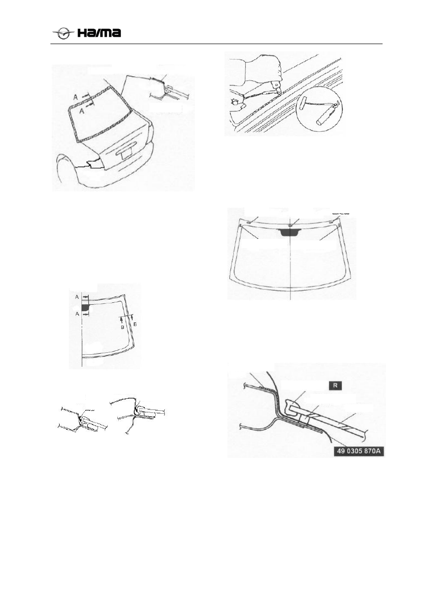
1.  Use the tool shown in the figure to insert the 

steel wire into the sealant. 

2.  Cut the sealant by pulling the tool around the 

glass.  


3.   Remove the rear window.  

If the rear window is to be reused: 

1.  Use a awl to pierce the sealant from the inside 

to the outside, with a small hole formed. 
(Excluding the positions with fixators and 
distance blocks) 


Warning: 

●  Please wear gloves when using the piano 

string, or else your hand may be injured. 

2.  Pull the SST(piano string) through the small 

hole. 


3.  Wrap both ends of the piano string on the 

handle. 

Notice:  

●  A complete piano string should be adopted to 

prevent it from being fractured when cutting 
the sealant. 

4.  Cut the sealant along the glass edge together 

with another person. Don’t make the body 
scratched.  

Adhesive tape

A-A section

Centerline

A-A section

B-B section 

Flange

Flange 

Fixator 

Fixator 

Fixator

Distance block Distance block


Adhesive tape 

Trim strip  

Sealant  

Glass 

-------------------------------------------------------------------------------------------------------------------------------------------------------------


Body and Accessories 3C-18 


5.  Remove the rear window. 

6.  Remove the distance blocks and fixators. 


7.  Remove the rear window. 

Installing the rear window 

Warning: 

● 

Please wear gloves when using the scraper, or 
else your hand may be injured.  

Caution: 

●  In order to prevent the sealant against 

cracking or prevent the glass from being 
pushed out by the air flow when closing the 
door, please have all windows open, until the 
sealant is completely hardened. 


1.  Use a blade to cut off the used sealant on the 

windshield frame, with a layer of about 1-
2mm{0.04-0.07in} thick left. If the sealant of 
certain part is fully removed, please apply 
some prime paint on it after the grease is 
removed, let it dry for 30min and then apply 
some fresh sealant to form a coating of 
2mm{0.08in} thick. 


2.  Clean the marginal zone of 50.0mm{1.97in} 

wide along the circle between the glass and 
the body. 

3.  Align the trim strip lower corner with the 

windshield lower corner. (1) 

4.  Install the lower corner from the outer corner. 

(2) 

5.  Align the marks on the trim strip with the 

ceramic borderline. (3) 

6.  Install it from the lower edge to the upper 

edge and both sides. Take care not to pull out 
the corner. (4) 


7.  Paste a piece of weatherstrip at the position 

19.0mm{0.75in} distant from the edge along 
the lower edge of the glass. 


8.  Install the distance block into the hole. 

9.  Install the glass temporarily on the body and 

adjust the gap between the glass and the body.  

10.  Make a mark on the glass above V-groove of 

the distance block. 

11.  Ensure the gap between the upper edge and 

the body is 6mm{0.24in} and that between 
the side edge and the body is 5mm{0.20in}. 

Distance 
block


Distance block


Distance 
block

Fixator 

Fixator 

Ceramic borderline


Weatherstrip


Centerline


-------------------------------------------------------------------------------------------------------------------------------------------------------------


Body and Accessories 3C-19 


12.  Remove the rear window. 

13.  As shown in the figure, install the fixator on 

the body. 


14.  As shown in the figure, install the fixator and 

the distance block on the glass. 


Caution: 

●  Keep the bonding part free from any greasy 

dirt and dust. Don’t touch the surface by hand; 
otherwise, the bonding material cannot stick 
the glass well with the body surface, resulting 
in leakage. 

15.  Use a brush to apply the prime paint on the 

bonding area between the glass and the body, 
as shown in the figure. Only the special prime 
paint for glass can be applied on the glass and 

only the special prime paint for body can be 
applied on the pedestal. Let the paint dry for 
about 30min. 


16.  After the prime paint gets dry, apply a layer of 

sealant (thickness: 14.0mm{0.55in}, width: 
8.0mm{0.31in}) around to fill up the gap 
between the weatherstrip and the glass. 


17.  Align the mark on the glass with the V-groove 

of the distance block and install the glass on 
the vehicle. 

18.  Press the glass inside by force to compress the 

sealant. 

19.  Ensure the gap between the upper edge and 

the body is 6mm{0.24in} and that between 
the side edge and the body is 9mm{0.35in}. 

Sealing Material Hardening Time 

Temperature

Surface 

hardening time 

Interval required 

before the vehicle 

can be used 

5℃{41℉}

About 1.5h 

About 12h 

20℃{68℉}

About 1h 

About 4h 

35℃{95℉}

About 10min 

About 2h 

20. 

Install the ceiling. (Refer to the 
Removal/Installation of Ceiling, Ceiling) 

21.  Install the high-mounted brake lamp. 


Fixator


Fixator


Distance block


Centerline


Centerline


Body


A-A section

B-B section

C-C section


-------------------------------------------------------------------------------------------------------------------------------------------------------------


Body and Accessories 3C-20 


Sliding Sunroof 


Removal/Installation of Deflector 

1.  Fully open the glass plate. 

2.  Remove the sliding sunroof unit to facilitate 

the removal of the fixator. (Refer to the 
Removal/Installation of Sliding Sunroof Unit) 

3.  Perform the removal in the order shown in the 

following table. 

4.  Perform the installation in reverse order of that 

shown in the table. 


1


Deflector 
Refer to the Removal Instruction 


2


Fixator 


Removal Instruction for Deflector 

●  Use a flat-end screwdriver wrapped with 

adhesive tape to remove the deflector.  


Removal/Installation of Glass Plate 

1.  Fully close the glass plate. 

2.  Fully open the sun visor. 

3.  Remove the screws and remove the glass 

plate. 


4.  Remove the weatherstrip of the glass plate.  


5.  Perform the installation in reverse order of the 

removal. 

6.  Adjust the position of the glass plate. (Refer 

to Adjusting the Glass Plate) 

Adjusting the Glass Plate 


1.  Fully close the glass plate. 

2.  Measure the clearance and height between the 

glass plate and the body.  

Clearance 


3.  If incorrect, loosen the mounting screw of the 

glass plate and relocate the glass plate. 

4.  Tighten the mounting screw of the glass plate. 

5.  Insert a preset card between the weatherstrip 

and the body. Ensure the sunroof is fully 

Screwdriver wrapped with 
adhesive tape


Push


Screw

Glass plate


Weatherstrip

A-A section

-------------------------------------------------------------------------------------------------------------------------------------------------------------


Body and Accessories 3C-21 


closed (some resistance can be felt when 
moving the preset card). If it not fully closed, 
repeat the steps 3 and 4 and readjust the 
position of the glass plate. 


Removing the front drain hose 

1. Remove the ceiling. (Refer to the 

Removal/Installation of Ceiling, Ceiling) 

2.  Remove the front wall grille. (Refer to the 

Removal/Installation of Front Wall Grille) 

3.  Remove the A-pillar trim plate. 

4.  Remove the front drain hose from the sunroof 

outer frame. 

5.  Remove the front drain hose from the clip. 

6.  Pull the front drain hose into the carriage.  

7.  Remove the front drain hose. 


Installing the front drain hose 

Caution: 

●  If certain part of the front drain hose is 

clamped or bent, the water inside the hose 
may not be drained, thus entering the carriage. 
During and after the installation of the trim 
plate and the ceiling, be sure to keep the front 
drain hose unobstructed. In case of any 
problem, deal with it immediately.  

1.  Apply some soapy water on the mounting 

position of the front drain hose. 

2.  Insert one end of the front drain hose into the 

sunroof frame.  

3.  Install the front drain hose into the clip along 

the pillar. 

4.  Insert the front drain hose plug into the 

hinged pillar hole. Install the front drain hose 
head into the clip. (Only for the right drain 
hose). It is located at the front drain basin. 

5. Install the ceiling. (Refer to the 

Removal/Installation of Ceiling, Ceiling) 

6.  Install the front wall grille. (Refer to the 

Removal/Installation of Front Wall Grille, 
Front Wall Grille) 

7.  Nstall the A-pillar trim plate. 

Removing the rear drain hose 

1.  Remove the high-mounted brake lamp. 

2.  Remove the C-pillar trim plate. 

3. Remove the ceiling. (Refer to the 

Removal/Installation of Ceiling, Ceiling) 

4.  Remove the side trim plates of the trunk. 

(Refer to the Removal/Installation of Trunk 
Side Trim Plate, Trim Plates) 

5.  Remove the rear drain hose from the sunroof 

outer frame. 

6.  Remove the rear drain hose from the clip. 

7.  Pull the front drain hose into the carriage. 

8.  Remove the rear drain hose. 


Installing the rear drain hose  

Caution: 

●  If certain part of the rear drain hose is 

clamped or bent, the water inside the hose 
may not be drained, thus entering the carriage. 
During and after the installation of the trim 
plate and the ceiling, be sure to keep the rear 
drain hose unobstructed. In case of any 
problem, deal with it immediately. 

1.  Apply some soapy water on the mounting 

position of the rear drain hose. 

2.  Insert one end of the rear drain hose into the 

sunroof frame. 

Preset card


Weatherstrip

Rubber 
ring


Body


Clip 

A-A section

Rubber ring 

Body

-------------------------------------------------------------------------------------------------------------------------------------------------------------


Body and Accessories 3C-22 


3.  Install the front drain hose into the clip along 

the pillar. The hose should be straightened. 

4.  Insert the rear drain hose plug into the rear 

pillar hole. 

5.  Install the side trim plates of the trunk. (Refer 

to the Removal/Installation of Trunk Side 
Trim Plate, Trim Plates) 

6. Install the ceiling. (Refer to the 

Removal/Installation of Ceiling, Ceiling) 

7.   Install the high-mounted brake lamp. 

8.  Install the C-pillar trim plate. 

Removal/Installation of Sliding Sunroof 
Unit 

1.   Disconnect the negative cable of the battery. 

2.  Remove the high-mounted brake lamp. 

3. Remove the ceiling. (Refer to the 

Removal/Installation of Ceiling, Ceiling) 

4. Remove the glass plate. (Refer to 

Removal/Installation of Glass Plate) 

5.  Remove the front and rear drain hoses from 

the sliding sunroof frame. 

6.  Remove the ceiling harness from the sliding 

sunroof frame. 


7.  Remove the bolts and nuts and remove the 

sunroof.  


8.  Perform the installation in reverse order of the 

removal. 

9.  Adjust the position of the glass plate. (Refer 

to Adjusting the Glass Plate) 

Disassembly of Sliding Sunroof Unit 

1.  Remove the screw and then the rain gutter. 


2.  Remove the sun visor fixator. 

3.  Slide the sun visor backward and remove it 

from the sunroof outer frame. 


4.  Remove the bolts and then the rear rain gutter.  


5.  Slide the rain gutter support backward and 

remove it from the sunroof outer frame.  


Clip 

Ceiling harness

Sun visor 
fixator 

Sun visor

Bolt 

Rear rain gutter

Bolt 

Nuts 

Nuts 

Screw

Rain gutter

Sunroof Unit 

Rain gutter 
support 

-------------------------------------------------------------------------------------------------------------------------------------------------------------


Body and Accessories 3C-23 


6.  Remove the sunroof motor. (Refer to 

Removing the Sunroof Motor) 

7.  Remove the set screw. 

8.  Slide the guide rail backward and remove it 

from the sunroof outer frame. 


9. Remove the deflector. (Refer to the 

Removal/Installation of Deflector) 

Assembly of Sliding Sunroof Unit 

1. Install the deflector. (Refer to the 

Removal/Installation of Deflector) 

2.  Slide the guide rail forward and install it into 

the sunroof outer frame.  

3.  Install the set screw. 


4.  Move the guide rail by hand until it is tilted 

up.  

5.  Move the linkage inside the guide rail by 

hand until the mark A is aligned with the mark 
B.  


6.   Install the sunroof motor. (Refer to Installing 

the Sunroof Motor) 

7.  Slide the rain gutter support forward and 

insert it into the sunroof outer frame.  


8.  Clean the residual repair sealant with the 

unleaded gasoline. . 

9.  Install the screws and then the rear rain gutter. 


10.  Slide the sun visor forward and install it into 

the outer frame. 

11.  Install the sun visor fixator. 


Set screw 

Guide rail 

Set screw 

Guide rail 

Guide rail 

Mark A 

Mark B 

Linkage 

Rain gutter 
support 

Sun visor 
fixator 

Sun visor  

Bolt 

Rear rain 
gutter 

-------------------------------------------------------------------------------------------------------------------------------------------------------------


Body and Accessories 3C-24 


12.  Install the screw and then the rain gutter. 


Removing the Sliding Sunroof Motor 

1.  Disconnect the negative cable of the battery. 

2.  Remove the high-mounted brake lamp. 

3. Remove the ceiling. (Refer to the 

Removal/Installation of Ceiling, Ceiling) 

4.  Disconnect the connector. 

5.  Remove the screw and then the sunroof motor. 


Installing the Sliding Sunroof Motor 

1.  Connect the sunroof motor connector. 

2.  Connect the sunroof switch connector. 

3.  Connect the negative cable of the battery. 

4.  Turn the ignition switch to the ON position. 

5.  Press the Close end of the slide switch until 

the sunroof motor stops. 

6.  Disconnect the sunroof switch connector. 

7.  Install the screw and then the sunroof motor. 

8. Install the ceiling. (Refer to the 

Removal/Installation of Ceiling, Ceiling) 

9.  Install the high-mounted brake lamp. 

Checking the Sunroof Motor 

Motor 

Remove the sunroof motor. (Refer to Removing 

the Sunroof Motor) 

1.  Connect the positive cable of the battery with 

the pin of the sunroof motor and check the 
operating condition of the motor. 

B+: Battery positive voltage 


Pin 

2A 2B 

Operating condition of motor 

B+ 

GND

Turn left (closed/tilted up) 

GND 

B+ 

Turn right (open/tilted down) 


2.   If incorrect, replace the sunroof motor. 

Limit Switch 

1. Remove the ceiling. (Refer to the 

Removal/Installation of Ceiling, Ceiling) 

2.  Disconnect the connector. 

3.  Use an ohmmeter to check the continuity 

between the pins of the sunroof motor. 


Screw  

Rain gutter  

Sunroof motor 

Screw 

Connector 

Open/tilted 
down 

Closed/tilted 
up 

Turn right   

Turn left     

Glass plate 

position

Continuity

Pin 

Fully open

Fully 

closed


Tilted up

-------------------------------------------------------------------------------------------------------------------------------------------------------------


Body and Accessories 3C-25 


4.  If incorrect, replace the sunroof motor. 

Sunroof relay 

1. Remove the ceiling. (Refer to the 

Removal/Installation of Ceiling, Ceiling) 

2.   Connect the sunroof switch connector. 

3.  Connect the negative cable of the battery. 

4.  Refer to the following indicators to check the 

voltage of the relay pins. 

5. Please 

disconnect 

the 

sunroof relay connector 

before checking the Pin 1F. 

6.  If incorrect, check the parts and relevant 

harness listed under the “Inspection Section”.  

7.  If the parts and relevant harness are normal but 

the system still cannot operate normally, 
replace the sunroof relay. 


TERMNAL NO  TERMNAL NAME 

CONTENTS OF SGNAL 

1 FREE 

------------- 

2 GND 

GROUND 

IGN 

GN SW SIGNAL 
GNTON SW SGNAL 

UP 

OPERATON SWTCH (TLT UP) 

OPEN 

OPERATON SWTCH(SLDE OPEN) 

+B 

+B POWER SUPPLY 
+B PCWER 

7 FREE 

--------------- 

8 FREE 

--------------- 

9 FREE 

--------------- 

10 

CLOSE 

OPERATON SWTCH (SLDE CLOSE/ DOWN) 


Notice:  

●  The sunroof switch is located together with 

the reading lamp.  

1.  Disconnect the negative cable of the battery. 

2. 

Remove the reading lamp. 
(Removal/Installation of Reading Lamp, 
Interior Lighting System, Section T) 

3.  Perform the installation in reverse order of the 

removal. 

Checking the sliding sunroof switch 

1. Remove the sliding sunroof switch. 

(Removal/ Installation of Reading Lamp, 
Interior Lighting System, Section T) 

2.  Use an ohmmeter to check the continuity 

between the pins of the sliding sunroof switch. 

3.  If incorrect, replace the sliding sunroof switch. 


-------------------------------------------------------------------------------------------------------------------------------------------------------------


Body and Accessories 3C-26 


Removal/Installation of Instrument Panel 

1.  Disconnect the negative cable of the battery. 

2.  Remove the left lower panel assembly 

(MA12-64-280). 

3.  Remove the left storage box assembly 

(MA12-64-610). 

4.  Remove the glove box (MA12-64-030). 

5.  Remove the airbag module from the steering 

wheel and remove the steering wheel from the 
steering column. (Refer to 
Removal/Installation of Steering Wheel). 

6.  Remove the steering column cover from the 

steering column. 

7.  Remove the steering column. (Refer to 

Removal/I nstallation of Steering Column). 

8.  Remove the left switch block. (Refer to 

Removal/ Installation of Left Switch Block) 

9.  Remove the combination instrument mask 

assembly and then the combination 
instrument.  

10.  Remove the central air outlet panel assembly, 

the CD panel assembly and the A/C controller 
successively.  

11.  Remove the auxiliary fascia console. (Refer to 

the Removal/Installation of Auxiliary Fascia 
Console). 

12.  Remove the connection between the engine 

hood opening cable and the trim cover.  

13.  Remove the A-pillar trim plate. (Refer to 

Removal/I nstallation of A-Pillar Trim Plate). 

14.  Remove the left and right side panels. 

15.  Disconnect every connector. 

16.  Remove the mounting bolts connected with 

the body. (As shown in the figure) 


17.  Remove the instrument panel body assembly 

(MA22-60-410) from the vehicle. 

(1) Make the instrument panel slowly titled 

forward.  

(2)  Lift up the instrument panel while it is tilting 

forward.  

(3)  Remove the instrument panel from the front 

passenger door.  

18. Remove the harness mounted on the 

instrument panel support. (Refer to the 
harness part) 

19.  Perform the installation in reverse order of the 

removal. 


Disassembly/Assembly of Instrument 
Panel Body Assembly  

1.  Perform the disassembly in the order shown 

in the following table. 

2.  Perform the assembly in reverse order of the 

removal. 


-------------------------------------------------------------------------------------------------------------------------------------------------------------


Body and Accessories 3C-27 


1  Side air vent assembly (left)(right) 

2  Instrument panel harness assembly 

3  Instrument panel support assembly 

4  Central A/C duct assembly  

5 Defroster 

6  Side defrosting grille (left) 

7 Iron 

support 

Combination instrument mask mounting
bracket 

9 Sensor 

manhead 

10  Glove box baffle  

11  Defrosting air duct bracket - middle 

12 

Front positioning bracket, instrument
panel 

13 Instrument 

panel 

body 

Removal/Installation of Left Lower Panel 

2.1 Use a flat-end screwdriver wrapped with 

adhesive tape to pry up the upper end of the 
left lower panel and remove the clip A. 

2.2 Rotate downward to make the guide pin 

separated from the instrument panel body. 

2.3  If a interior temperature sensor is equipped, 

remove the sensor. 

2.4  Pull out the left lower panel in the direction 

shown in the figure.  


2.5  Perform the installation in reverse order of the 

removal. 

Removal/Installation of Left Storage Box 

3.1  Open the left storage box, pull it out in the 

direction shown in the figure while rotating, 
to make it separated from the rotating shaft.  

3.2   Remove the left storage box. 


3.3.  Perform the installation in reverse order of the 

removal. 

Removal/Installation of Glove Box 

4.1. Rotate the glove box stop block inside to 

loosen and remove it. 

4.2.  Open the glove box, pull it up while rotating, 

to make it separated from the rotating shaft. 

4.3.  Remove the glove box. 


4.4 

Perform the installation in reverse order of 

the removal. 

Removal/Installation of Steering Column 
Cover 

6.1 Use a flat-end screwdriver wrapped with 

adhesive tape to pry up the upper cover of the 
steering column to make it separated from the 
lower cover. 

6.2  Pull out the steering column dust pad and turn 

it upside down, and remove the steering 
column upper cover. 

6.3 Remove screws and the steering column 

lower cover.  

6.4  Perform the installation in reverse order of the 

removal. 


Stop block


-------------------------------------------------------------------------------------------------------------------------------------------------------------


Body and Accessories 3C-28 


Removal/Installation of Combination 
Instrument Mask 

9.1  Remove the self-tapping screw and use a flat-

end screwdriver wrapped with adhesive tape 
to pry up the combination instrument mask.  

9.2 Remove the combination instrument mask 

assembly. 


9.3  Perform the installation in reverse order of the 

removal. 

Removal/Installation of Central Air 
Outlet Panel 

10.1 Use a flat-end screwdriver wrapped with 

adhesive tape to pry up the hazard warning 
lamp switch and remove the connector. 

10.2 Move up the remove the central air outlet 

assembly and pull out the iron clip and the 
plastic clip respectively to make it separated 
from the A/C duct.  

10.3 Perform the installation in reverse order of the 

removal. 


Removal/Installation of Front Passenger 
Airbag Cover Plate  

1.  Remove the instrument panel body assembly 

from the vehicle. 

2.  Turn the instrument panel body assembly over 

and remove the screws for connecting the 
airbag module and the instrument panel cross 
member. 


3.  Remove 9 screws for connecting the front 

passenger airbag cover plate and the 
instrument panel body. 


4.  Use a flat-end screwdriver wrapped with 

adhesive tape to pry up the plastic clips 
successively front the rear end. 

5.  Pull it out, as shown in the figure. 


6.  The installation is in reverse order of the 

removal. 

Removal/Installation of Auxiliary Fascia 
Console 

11.1 Remove the ashtray.  

11.2 Remove the gear shift panel assembly. 

a)  Unscrew the shift lever ball head (this 

operation is unnecessary for the AT model). 

b)  Use a flat-end screwdriver wrapped with 

adhesive tape to pry up the plastic clips 
successively front the rear end. 

c)  Pull out the gear shift panel assembly, as 

shown in the figure. 


-------------------------------------------------------------------------------------------------------------------------------------------------------------


Body and Accessories 3C-29 


11.3 Remove 2 self-tapping screws for connecting 

the front end of the auxiliary fascia console 
body and the instrument panel body. 


11.4 Pull up the hand brake, remove its small cover 

plate and then the self-tapping screws.  


11.5 Open the armrest box cover (this operation is 

unnecessary for the low configuration model), 
take out the gasket from the bottom of the 
armrest box and remove the bolts.  


11.5 Remove the left and right cap screws, remove 

the auxiliary fascia console body in the 
direction shown in the figure, lift it up slowly 
and remove the auxiliary fascia console.  

Disassembly/Assembly of Auxiliary Fascia 
Console Assembly  

Perform the disassembly in the order shown in the 
following table.  

Perform the installation in reverse order of the 
removal. 


1


Rear ashtray


2


Mounting plate, rear ashtray


3


Rear trim plate assembly


4


Rotating shaft card


5


Rotating shaft


6


Armrest box cover plate assembly


7


Switch snap fastener


8


Sound-absorbing sponge 

9


Armrest box pad


10

Auxiliary fascia console body


Removal/Installation of  Left/Right Cover 

Remove the screw. 

Pull the sun visor body to the direction shown by 
the arrow and loosen the mount on the body. 


Perform the installation in reverse order of the 
removal. 

Interior Trimming 

Removal/Installation of A-Pillar Trim 
Plate 

Turn over the joint panel.  

Use a fastening screw puller to loosen the clips A 
and B.  

Pull up the A-pillar trim plate. 


Mount 

Screw 

Sun visor body 

-------------------------------------------------------------------------------------------------------------------------------------------------------------


Body and Accessories 3C-30 


Perform the installation in reverse order of the 
removal. 

Removing the B-pillar Lower Trim Plate  

Remove the front and front doorsill footboards. 

Remove the front and rear doorsill footboards. 

Pull the position marked with A and remove one 
side of the B-pillar lower trim plate. 


Installing the B-pillar Lower Trim Plate 

Insert the position B of the B-pillar lower trim 
plate into the square hole of the B-pillar upper trim 
plate. 

Align the clip A of the B-pillar lower trim plate 
with the body hole and beat it in. 

Install the weatherstrips of the front and rear door 
frames.  

Install the inner footboard of the rear doorsill. 

Removal/Installation of B-Pillar Upper 
Trim Plate 

Remove the fixator from the front seat belt. (Refer 
to Removal/Installation of Front Seat Belt, Seat 
Belts) 

Remove the B-pillar lower trim plate. (Refer to the 
Removal/Installation of B-Pillar Lower Trim Plate) 

Pull open the upper end of the front/rear door 
frame weatherstrips. Use a phillips screwdriver to 

remove the self-tapping screw B. 

Use a fastening screw puller to loosen the clip A.  


Perform the installation in reverse order of the 
removal. 

Removal/Installation of Inner Footboard 
of Front Doorsill 

Pull the front doorsill footboard assembly to 
separate the clips A and B from the body. 


Perform the installation in reverse order of the 
removal. 

Removal/Installation of Rear Doorsill 
Footboard 

1.  Pull the rear doorsill inner footboard to 

separate the clips A and B from the body. 


Perform the installation in reverse order of the 
removal. 

-------------------------------------------------------------------------------------------------------------------------------------------------------------


Body and Accessories 3C-31 


Removal/Installation of C-Pillar Trim 
Plate 

Turn over the joint panel.  

Use a fastening screw puller to remove the clips A 
and B. 

Pull up the C-pillar trim plate. 


Perform the installation in reverse order of the 
removal. 

Removal/Installation of Front Door Trim 
Plate 


1.  Disconnect the negative cable of the battery. 

2.  Remove the screw cap A. 

3.  Remove the self-tapping screw B. 


4.  Remove the screw cap C. 

5.  Remove the screw D. 

6.  Remove the inner handle E. 


7.  Disconnect the power window main switch 

and auxiliary switch plugs. (Only for the 
driver side) 

8.  Remove the switch panel F. 

9.  Remove the coin box pad G. 

10.  Remove the screw H. 


11.  Remove the screw J. 

12.  Disconnect the courtesy lamp main switch 

and auxiliary switch plugs. 

13.  Remove the door lamp (courtesy lamp cover) 

K. 


14.  Remove the front door trim triangle L 

15.  In order to loosen 9 clips M, you should put 

your hand into the opening of the door trim 
plate map bag to pull the door trim plate 
outward.  

-------------------------------------------------------------------------------------------------------------------------------------------------------------


Body and Accessories 3C-32 


16.  Perform the installation in reverse order of the 

removal. 


Removal/Installation of Rear Door Trim 
Plate 


1.  Disconnect the negative cable of the battery. 

2.  Remove the screw cap A. 

3.  Remove the screw B. 

4.  Remove the inner handle C. 


5.  Remove the coin box pad D 

6.  Remove the screw E. 


7.  Disconnect the power window switch plug.  

8.  Remove the switch panel F. 

9.  Remove the screw G. 

10.  Remove the rear door trim triangle H. 

11.  In order to loosen 8 clips M, you should put 

your hand into the opening at the bottom of 
the door trim plate to pull the door trim plate 
outward. 


12.  Perform the installation in reverse order of the 

removal. 

-------------------------------------------------------------------------------------------------------------------------------------------------------------


Content      ..     3      4      5      6     ..