Vauxhall Vivaro C (2023 year). Manual in english - page 3
 

  Index      Manuals     Vauxhall Vivaro C (2023 year). Manual in english


Search            copyright infringement  


Content      ..     1      2      3      4      ..


Vauxhall Vivaro C (2023 year). Manual in english - page 3


70

Storage

Lashing eyes

The lashing eyes are designed to

secure items against slippage, e.g.

using lashing straps or luggage net.
Lashing eyes may be located on the

vehicle floor. The number and

location of the lashing eyes may vary

depending on the vehicle.

Cargo management system

Flap behind the passenger seat

Depending on version, a partition

behind the front seats protects the

driver and front passengers against

the risk of load movement.
There may be a flap in the partition

behind the passenger seat which can

be removed to accommodate long

objects.
If the outer passenger seat is folded

and the flap is open, the centre seat

has to stay free.

Removing the flap

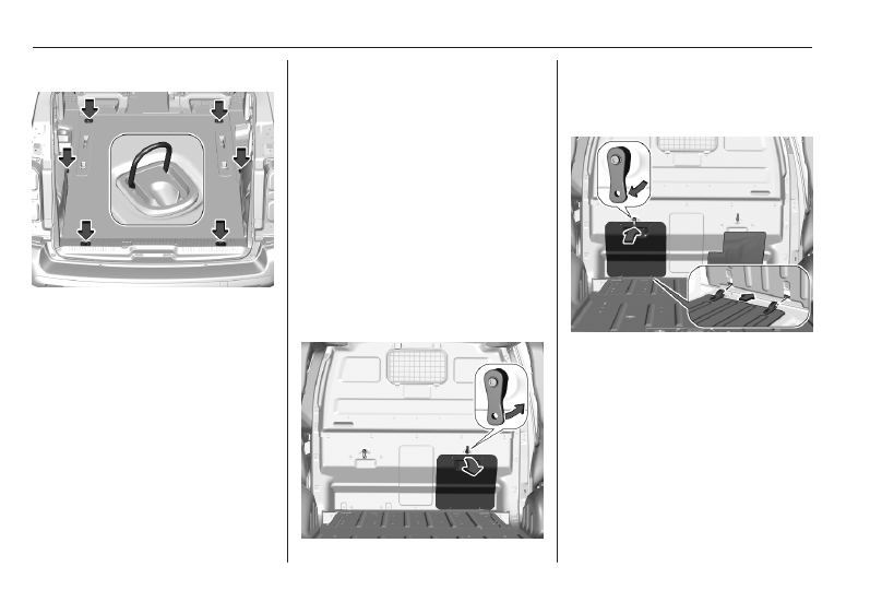
1. Release the locking device, lower

the flap and then remove it.

2. Stow the flap behind the driver's

seat.

Turn the locking device upwards.

Put the hinges of the flap in their

housing, lift the flap and close the

locking device.
Storage

71

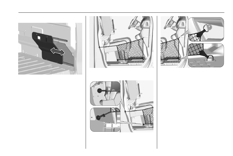
Sliding the flap

Slide the flap to the side. It is kept in

position by magnets.

Fitting the protective net

The protective net must be installed

whenever the bench seat of the front

passenger side is folded and the

partition flap is open.

1. Lift the seat cushion of the bench

seat of the front passenger side.
Seat folding 

3

 36.

2. Fix the net like shown on the

picture.

3. Fit the attachment in the opening.

To lock the attachment turn it

clockwise a quarter turn.

4. Attach the hooks to the lashing

eyes in the glovebox and on the

floor.

After transportation remove the

protective net and fold down the seat.

Second row bench seat in the

commercial vehicle

The bench seat in the second row can

be folded to increase the load

compartment.

72

Storage

9

Warning

When seats are being adjusted or

folded, keep hands and feet away

from the moving area. Risk of

injury.
Ensure that there are no objects

on the anchor points or rails.
Never adjust seats while driving as

they could move uncontrollably.
Drive only with engaged seats and

backrests.

Folding

1. Tilt the head restraints to the front.

Pull the loop upwards to unlock

the bench seat.

2. Raise the bench seat taking the

handle and fold the bench seat to

the front until it is engaged.

Unfolding

1. To restore the bench seat to the

original position pull the loop to

unlock it.

2. Take the handle to fold the bench

seat to the back until it is engaged

in the original position.
Tilt up the head restraints.

Safety net

Safety net behind the seats

Depending on version, the safety net

can be installed behind the second

row seats, the third row seats or

behind the front seats.
To increase the loading capacity the

seats behind the safety net can be

folded or removed.
Rear seats 

3

 39.

Seat backrests in front of the safety

net must be raised up.
Passengers must not be transported

behind the safety net.

Storage

73

Installation in the roof frame

1. There are installation openings on

both sides in the roof frame. If

present, open the covers.

2. Suspend and engage the rod of

net at one side, compress rod and

suspend and engage at the other

side.

Installation on the floor

1. a) Installation with lashing eyes

Attach the hooks of safety net

straps in the lashing eyes.
Lashing eyes 

3

 70.

b) Installation with rear seats on

rails

Insert the fixings in the floor

anchorages on both sides. To lock

the fixings turn them clockwise a

quarter turn. Place them as close

as possible to the end of the rail.
c) Installation with fixed rear seats

Insert the fixings in the floor

anchorages on both sides.

74

Storage

It is possible to install the safety

net together with folded seats.
Folded seats 

3

 39.

2. Tension both straps by pulling at

the loose end.

Safety net on the floor

Attached to the lashing eyes on the

rear floor, it allows objects to be held

down.
Lashing eyes 

3

 70.

Additional storage

features

Folding tray

Trays may be located on the

backrests of the front seats.
Fold down the tray. The tray contains

a cupholder and a strap to secure

objects.
Do not place any hard or heavy

objects on the tray.

Storage

75

Document tray in the centre

seatback

The front centre passenger seat

backrest can contain a document

tray.
Fold down the tray. The document

tray contains a storage compartment

and a swivelling shelf.
Return the swivelling shelf to its

original position before raising the

tray.

Table

Multifunctional table

The multifunctional table can be

positioned in second or third row.

To move the multifunctional table pull

the handle in the front without going

beyond the point of resistance. Slide

the multifunctional table forwards or

backwards. Release the handle when

it is in the desired position. Make sure

that the multifunctional table is

securely engaged.

76

Storage

Storage compartment in the

multifunctional table

Press the cover to open the storage

compartment.
The maximum permitted load is 3 kg.

Unfolding

To unfold the multifunctional table pull

the handle on the top. Pull the rear

part to the vertical position until it

engages.

On the two sides there are tables

located. Pull the table fully up and

then move it into the horizontal

position.
Each table can bear a maximum load

of 10 kg.

Caution

To avoid damaging the table tops

never unfold the table when it is

between individual seats.

Storage

77

Folding

To staw the table use the handle to

move it back in the folded position.
To fold the multifunctional table pull

the handle and move the rear part

downwards until it engages.

Removing

To remove the multifunctional table

pull the handle in the front beyond the

point of resistance. Remove the

multifunctional table.

Refitting

The multifunctional table can be fitted

in two positions.

78

Storage

The handle in the front has to be in the

tightened position. Place the rear of

the multifunctional table on the rail

and tip the front down. Slide the

multifunctional table until it engages.

9

Warning

Never use the multifunctional table

in the unfolded position while the

vehicle is in motion. Any objects

on the table will turn into

projectiles in the event of a sudden

stop or collision.
Ensure that the multifunctional

table is correctly folded before

moving or removing it.
Never use the tables as seats or

lean on them.
Check that there is no object

obstructing the rail and preventing

locking.

Roof rack system

Roof rack

For safety reasons and to avoid

damage to the roof, the vehicle

approved roof rack system is

recommended. For further

information contact your workshop.
Follow the installation instructions

and remove the roof rack when not in

use.
The roof load is the combined weight

of the roof rack and the load.
Loading information 

3

 79.

Mounting

Fasten the roof rack according to the

installation instructions delivered with

the roof rack.

The number and location of the

mounting points may vary depending

on the vehicle:

Vehicles with glass panel

Mount two roof bars using the

mounting points marked in the

picture.
Permissible roof load L1, L2, L3 max.

100 kg.

Storage

79

Vehicles without glass panel

Mount three roof bars using the

mounting points marked in the

picture.
Permissible roof load L1, L2, L3 max.

150 kg.

Mount the roof rack using the

mounting points marked in the

picture.
Permissible roof load L1 max.

140 kg.
Permissible roof load L2, L3 max.

170 kg.
Vehicle dimensions 

3

 354

Loading information

9

Warning

Always make sure that the load in

the vehicle is securely stowed.

Otherwise objects can be thrown

around inside the vehicle and

cause personal injury or damage

to the load or car.

● Heavy objects in the load

compartment should be placed

against the seat backrests. Make

sure that the backrests are

80

Storage

securely engaged. If objects can

be stacked, heavier objects

should be placed at the bottom.

● Prevent sliding of loose objects

by securing them with straps

attached to the lashing eyes.
Lashing eyes 

3

 70.

● Do not allow the load to protrude

above the upper edge of the

backrests.

● Do not place any objects on the

rear luggage cover or the

instrument panel, and do not

cover the sensor on top of the

instrument panel.

● The load must not obstruct the

operation of the pedals, parking

brake and gear selector, or

hinder the freedom of movement

of the driver. Do not place any

unsecured objects in the interior.

● Do not drive with an open load

compartment.

● The payload is the difference

between the permitted gross

vehicle weight (see identification

plate) and the EC kerb weight.
Identification plate 

3

 349.

To calculate the payload, enter

the data for your vehicle in the

weights table at the front of this

manual.
The EC kerb weight includes

weights for the driver (68 kg),

luggage (7 kg) and all fluids (fuel

tank 90% full).
Optional equipment and

accessories increase the kerb

weight.

● Driving with a roof load increases

the sensitivity of the vehicle to

cross-winds and has a

detrimental effect on vehicle

handling due to the vehicle's

higher centre of gravity.

Distribute the load evenly and

secure it properly with retaining

straps. Adjust the tyre pressure

and vehicle speed according to

the load conditions. Check and

retighten the straps frequently.
Do not drive faster than 75 mph.

Instruments and controls

81

Instruments and

controls

Instrument panel overview ........... 83
Controls ....................................... 85

Steering wheel adjustment ........ 85

Steering wheel controls ............. 85

Horn ........................................... 86

Pedestrian safety alert ............... 86

Steering column controls ........... 86

Windscreen wiper and washer . . 86

Rear window wiper and

washer ...................................... 88

Outside temperature .................. 89

Clock ......................................... 89

Power outlets ............................. 89

Warning lights, gauges and indi‐

cators ........................................... 91

Speedometer ............................. 91

Odometer .................................. 92

Trip odometer ............................ 92

Tachometer ............................... 93

Fuel gauge ................................ 93

High voltage battery gauge ....... 94

Power indicator gauge ............... 94

Comfort consumption gauge ..... 95

Engine coolant temperature

gauge ....................................... 95

Engine oil level monitor ............. 96

Service display .......................... 96

Control indicators ...................... 97

Turn lights .................................. 99

Seat belt reminder ..................... 99

Airbag and belt tensioners ......... 99

Airbag deactivation .................. 100

Charging system ..................... 100

Malfunction indicator light ........ 100

Service vehicle soon ............... 100

Stop engine ............................. 100

System check .......................... 101

Brake system ........................... 101

Parking brake .......................... 101

Electric parking brake .............. 101

Electric parking brake fault ...... 101

Automatic operation of electric

parking brake off .................... 101

Antilock brake system (ABS) ... 102

Gear shifting ............................ 102

Lane departure warning .......... 102

Electronic Stability Control and

Traction Control system ......... 102

Engine coolant temperature .... 102

Preheating ............................... 103

Exhaust filter ............................ 103

AdBlue ..................................... 103

Deflation detection system ...... 103

Engine oil pressure .................. 103

Low fuel ................................... 104

Charging cable connected ....... 104

Vehicle ready ........................... 104

Reduced engine power ........... 104

Autostop .................................. 104

Exterior light ............................ 104

Low beam ................................ 104

High beam ............................... 104

High beam assist ..................... 104

LED headlights ........................ 105

Front fog lights ......................... 105

Rear fog light ........................... 105

Rain sensor ............................. 105

Cruise control .......................... 105

Semi-adaptive cruise control ... 105

Pedestrian safety alert fault ..... 105

Side blind spot alert ................. 105

Active emergency braking ....... 105

Speed limiter ........................... 105

Door open ................................ 105

Displays ..................................... 106

Driver Information Centre ........ 106

Info Display .............................. 112

Head-up display ...................... 113

Vehicle messages ...................... 115

Warning chimes ....................... 115

Vehicle personalisation .............. 116

82

Instruments and controls

Telematics services ................... 120

Emergency call ........................ 120

Vauxhall Connect .................... 121

ERA GLONASS ....................... 121

Instruments and controls

83

Instrument panel overview

84

Instruments and controls

1

Power windows ..................... 27

2

Exterior mirrors ..................... 24

3

Side air vents ...................... 216

4

Selective ride control .......... 245

5

Turn lights ........................... 127
Headlight flash .................... 125
High beam ........................... 124
Exit lighting .......................... 131

6

Head-up display controls .... 113

7

Steering wheel controls ........ 85

8

Steering wheel paddles ........ 85

9

Instruments ........................... 91
Driver Information Centre .... 106

10 Button for Driver

Information Centre .............. 106
Windscreen wiper and

washer .................................. 86
Rear wiper and washer ......... 88

11 Head-up display .................. 113
12 Air vents .............................. 216
13 Control elements for Info

Display ................................ 112

14 Info Display ......................... 112
15 Climate control system ........ 207
16 Storage compartment ........... 67
17 Storage compartment ........... 67
18 AUX input
19 Power outlet .......................... 89
20 Airbag deactivation ............... 51
21 USB port ............................... 89
22 Seat heating .......................... 37
23 Electronic Stability Control

and Traction Control ........... 244
Tyre deflation detection

system ................................. 322
Stop-start system ................ 224
Heated windscreen ............... 29
Electric child locks ................. 14
Central locking system .......... 10

24 Hazard warning flashers ..... 126
25 Manual transmission ........... 238

Automatic transmission ....... 234

26 Power button ....................... 221
27 Automatic locking .................. 14

28 Ignition switch ..................... 220
29 Control elements for

Infotainment system

30 Steering wheel adjustment . . . 85
31 Fuse box ............................. 317
32 Horn ...................................... 86
33 Cruise control ...................... 246

Speed limiter ....................... 250
Semi-adaptive cruise

control ................................. 253

34 Bonnet release lever ........... 299
35 Anti-theft alarm system ......... 21

Lane departure warning ...... 274
Side blind spot alert ............ 268
Parking assist ...................... 265
Temperature

preconditioning ................... 214
Headlight range adjustment 125
High beam assist ................ 124

Instruments and controls

85

Controls

Steering wheel adjustment

Unlock lever, adjust steering wheel,

then engage lever and ensure it is

fully locked.
Do not adjust steering wheel unless

vehicle is stationary and steering

wheel lock has been released.

Steering wheel controls

The menus and functions of the

Driver Information Centre can be

selected via the rotary knob on the left

steering wheel stalk.
Driver Information Centre 

3

 106.

Infotainment system can be operated

via the steering wheel controls.

Steering wheel paddles

On vehicles with automatic

transmission, gearshifting can be

operated via + or -.
Automatic transmission 

3

 234.

Manual mode 

3

 234.

86

Instruments and controls

Horn

Press 

d

.

Pedestrian safety alert

The sound of the pedestrian safety

alert is generated to indicate the

vehicle presence to pedestrians. It is

active up to 19 mph.

Steering column controls

Cruise control, semi-adaptive cruise

control and speed limiter are

operated via the driver assistance

control on the left side of the steering

column.
Cruise control 

3

 246.

Speed limiter 

3

 250.

Semi-adaptive cruise control 

3

 253.

Windscreen wiper and

washer

Windscreen wiper with adjustable

wiper frequency

2

: fast

1

: slow

INT : interval wiping

0

: off

For a single wipe when the

windscreen wiper is off, press the

lever down.
Do not use if the windscreen is frozen.
Switch off in car washes.

Instruments and controls

87

To activate interval wiping mode the

next time ignition is switched on,

press the lever downwards to position

0 and back to INT.

Windscreen wiper with rain

sensor

2

: fast

1

: slow

INT

: interval wiping

0

: off

AUTO : automatic wiping with rain

sensor

In AUTO position, the rain sensor

detects the amount of water on the

windscreen and automatically

regulates the frequency of the

windscreen wiper. To deactivate the

automatic wiping mode, press the

lever downwards to AUTO again.
If ignition is switched off for more than

a minute, automatic wiping mode is

deactivated. To activate automatic

wiping mode the next time ignition is

switched on, press the lever

downwards to AUTO again.
For a single wipe when the

windscreen wiper is off, pull the lever

briefly towards you.
Do not use if the windscreen is frozen.
Switch off in car washes.

Windscreen washer

Washer fluid is sprayed onto the

windscreen and the wiper wipes a few

times.
Washer fluid 

3

 302.

88

Instruments and controls

Functionality of the rain sensor

Keep the sensor free from dust, dirt

and ice.
Control indicator 

y


3

 86.

Rear window wiper and

washer

Rear window wiper

0 : off

S

: intermittent operation

R

: rear window washer

Do not use if the rear window is

frozen.
Switch off in car washes.
The rear window wiper comes on

automatically when the windscreen

wiper is switched on and reverse gear

is engaged.

Activation or deactivation of this

function can be changed in the

Vehicle personalisation menu 

3

 116.

Rear window washer

Set to 

R

.

Washer fluid is sprayed onto the rear

window and the wiper wipes a few

times.
The rear window washer system is

deactivated when the fluid level is

low.
Washer fluid 

3

 302.

Instruments and controls

89

Outside temperature

Illustration shows an example.
If outside temperature drops to 3 °C,

a warning message is displayed in the

Driver Information Centre.

9

Warning

The road surface may already be

icy even though the display

indicates a few degrees above 0

°C.

Clock

Illustration shows an example.
Date and time are shown in the Info

Display.
The adjustment of date and time is

described in the Infotainment system

section.
Info Display 

3

 112.

Power outlets

A 12 V power outlet is located in the

glovebox.

90

Instruments and controls

A 12 V power outlet is located in the

centre console.

A 12 V  power outlet may be located

at the lower left side of the B-pillar.

A 12 V  power outlet may be located

on the third row left side trim.

Another 12 V  power outlet may be

located at the lower left side of the D-

pillar.
Do not exceed the maximum power

consumption of 120 W.

A 220 V power outlet may be located

underneath the front passenger seat.
Do not exceed the maximum power

consumption of 120 W.
With ignition off, the power outlets are

deactivated. Additionally the power

outlets are deactivated in the event of

low vehicle battery voltage.
Electrical accessories that are

connected must comply with the

electromagnetic compatibility

requirements laid down in

DIN VDE 40 839.
Do not connect any current-delivering

accessories, e.g. electrical charging

devices or batteries.

Instruments and controls

91

Do not damage the outlet by using

unsuitable plugs.
Stop-start system 

3

 224.

USB port

A USB port is located in the

instrument panel.
A USB port may be located within the

compartment located above the

glovebox.
A further USB port may be located in

the rear console.
The USB ports are prepared for

charging external devices and

provide a data connection to the

Infotainment system.

Notice

The sockets must always be kept

clean and dry.

Warning lights, gauges

and indicators

Speedometer

Indicates vehicle speed.

92

Instruments and controls

Odometer

The total recorded distance is

displayed in miles.

Trip odometer

The recorded distance since the last

reset is displayed in the Driver

Information Centre.

Baselevel instrument cluster

Trip odometer counts up to

9,999.9 miles without automatic

reset.
Press 

F

 for 2 seconds to reset

trip odometer.

Midlevel instrument cluster

Trip odometer counts up to

9,999.9 miles without automatic

reset.
Press SET 000 for 2 seconds to reset

trip odometer.

Instruments and controls

93

Uplevel instrument cluster

Trip odometer counts up to

1,999.9 miles and resets then

automatically.
Press 000 for 2 seconds to reset trip

odometer.
Driver Information Centre 

3

 106.

Tachometer

Displays the engine speed.
Drive in a low engine speed range for

each gear as much as possible.

Caution

If the needle is in the red warning

zone, the maximum permitted

engine speed is exceeded. Engine

at risk.

Fuel gauge

Displays the fuel level in the tank.
Never run the fuel tank dry.

The arrow indicates the vehicle side

where the fuel filler flap is located.
Because of the fuel remaining in the

tank, the top-up quantity may be less

than the specified tank capacity.
Baselevel cluster

A scale consisting of white segments

shows the fuel level.
If the control indicator 

r

 illuminates

yellow, refuel the tank immediately.

94

Instruments and controls

Midlevel and uplevel instrument

cluster

If the control indicator 

2

 illuminates

yellow, refuel the tank immediately.

High voltage battery gauge

The high voltage battery gauge

displays the charging level of the high

voltage battery.

Power indicator gauge

The power indicator gauge informs

about the current energy situation of

the vehicle.
Charge : High voltage battery is

being charged with energy

resulting from braking or

deceleration of the vehicle

Eco

: An optimum in energy is

accessible in all driving

modes

Power : Vehicle is driven in a

dynamic driving style with

focus on performance

Instruments and controls

95

Comfort consumption

gauge

The comfort consumption gauge

informs about the current electric

consumption caused by the following

thermal consumers:

● heating
● air conditioning
● heated windscreen
● heated rear window
● heated seats

If the drive mode Eco mode is

selected, the performance of the

thermal consumers is reduced. The

needle of the comfort consumption

gauge is in the ECO zone.

Engine coolant temperature

gauge

Displays the coolant temperature.

Caution

If engine coolant temperature is

too high, stop vehicle, switch off

engine. Danger to engine. Check

coolant level.

Baselevel cluster

A scale consisting of white segments

shows the engine coolant

temperature.
If the engine coolant temperature is

too high, the control indicator 

V

illuminates red.
Switch off engine immediately.

96

Instruments and controls

Midlevel and uplevel instrument

cluster

70 °C

: engine operating

temperature not yet

reached

90 °C

: normal operating

temperature

red zone : temperature too high
Control indicator 

2

 illuminates if

coolant temperature is too high.
Switch off engine immediately.

Engine oil level monitor

The state of the engine oil level is

displayed in the Driver Information

Centre for a few seconds following

the service information after switching

on the ignition.
A proper state of engine oil level is

confirmed.
If engine oil level is low, 

T

 flashes

and warning message is indicated in

the Driver Information Centre.

Depending on the version, 

D

flashes in the Driver Information

Centre. Confirm engine oil level by

using the oil dipstick and top up

engine oil respectively.
Engine oil 

3

 300.

A fault of measurement is indicated

by 

E

 or a message in the Driver

Information Centre together with

T

. Check engine oil level manually

by using the dipstick.

Service display

The service system informs when to

change the engine oil and filter or a

vehicle service is required. Based on

driving conditions, the interval at

which an engine oil and filter change

is required can vary considerably.
Service information 

3

 344.

A required service due is displayed in

the Driver Information Centre for

several seconds after switching on

the ignition.
If no service is required for the next

1800 miles or more no service

information appears in the display.
If service is required within the next

1800 miles, 

A

 illuminates temporary

as reminder. Simultaneously, the

remaining distance or time duration is

indicated for several seconds.

Depending on the version, the

distance travelled since the due date

is indicated in the Driver Information

Centre.
If service is required in less than

600 miles, 

A

 flashes and then

illuminates permanently. Remaining

distance or time duration is indicated

for several seconds. Simultaneously,

the remaining distance or time

duration is indicated for several

seconds. Depending on the version,

Instruments and controls

97

the distance travelled since the due

date is indicated in the Driver

Information Centre.
Overdued service is indicated by a

message in the Driver Information

Centre which indicates the overdued

distance. 

A

 flashes and then

illuminates permanently until service

is executed. Additionally, the control

indicator 

C

 or SERVICE

illuminates.

Reset of service interval

After each service, the service

indicator must be reset to ensure

proper functionality. It is

recommended to seek the assistance

of a workshop.
If service is executed by yourself,

operate as following:

● switch off ignition
● press and hold 

F

G

 or

CHECK

● switch on ignition, the distance

indication begins a countdown

● when the display indicates =0,

release the button and

A

 disappears

Retrieving service information

To retrieve the status of the service

information at any time press 

F

,

G

 or CHECK.

The service information is displayed

for a few seconds.
Instrument cluster 

3

 106.

Service information 

3

 344.

Control indicators

The control indicators described are

not present in all vehicles. The

description applies to all instrument

versions. Depending on the

equipment, the position of the control

indicators may vary. When the

ignition is switched on, most control

indicators will illuminate briefly as a

functionality test.
The control indicator colours mean:
red

: danger, important reminder

yellow : warning, information, fault

green : confirmation of activation

blue

: confirmation of activation

white : confirmation of activation

grey

: system paused, at least one

system limitation has been

detected

Control indicators are located in the

Driver Information Centre.
Driver Information Centre 

3

 106.

Overview

The numbers in the overview table

indicate what to do, when a control

indicator illuminates or flashes.
1 : only for information

2 : information and warning

3 : seek the assistance of a

workshop

4 : stop engine and seek the

assistance of a workshop

5 : have the cause of the fault

remedied immediately by a

workshop

6 : stop vehicle, do not continue the

journey and seek the assistance

of a workshop

98

Instruments and controls

1

1

Turn lights 

3

 99

a

2

Seat belt reminder

3

 99

d

5

Airbag and belt

tensioners 

3

 99

H

2

Airbag activated

3

 100

g

2

Airbag deactivated

3

 100

S

4

Charging system

3

 100

W

5

Malfunction indicator

light 

3

 100

X

2

System check 

3

 101

C

5

Service vehicle soon

3

 100

STOP 4

Stop engine 

3

 100

READY 1

Vehicle ready 

3

 104

i

5

Service vehicle soon

3

 100

h

1 /

5

Parking brake 

3

 101

i

2

Antilock brake system

(ABS) 

3

 102

ZY

2

Gear shifting 

3

 102

Q

2

Lane departure

warning 

3

 102

+

1 /

3

Exhaust filter 

3

 103

v

1

Cruise control 

3

 105

Q

1

Semi-adaptive cruise

control 

3

 105

5

1

Speed limiter 

3

 105

J

2 /

5

Electronic Stability

Control and Traction

Control system 

3

 102

V

4

Engine coolant temper‐

ature high 

3

 102

z

1

Preheating 

3

 103

B

1

AdBlue 

3

 103

q

2 /

3

Tyre deflation detec‐

tion system 

3

 103

T

4

Engine oil pressure

3

 103

r

2

Low fuel 

3

 104

j

2

Charging cable

connected 

3

 104

n

1

Autostop 

3

 104

1

1

Exterior light 

3

 104

D

1

Low beam 

3

 104

A

1

High beam 

3

 104

B

1

High beam assist

3

 104

G

1

Front fog lights 

3

 105

H

1

Rear fog light 

3

 105

y

1

Rain sensor 

3

 105

,

2

Side blind spot alert

3

 105

K

3

Pedestrian safety alert

fault 

3

 105

Instruments and controls

99

m

2 /

3

Active emergency

braking 

3

 105

O

2

Door open 

3

 105

N

2

High voltage battery

gauge 

3

 94

M

2

Reduced engine power

3

 104

Turn lights

1

 flash green.

Flash

Turn lights or the hazard warning

flashers are activated.
Rapid flashing: failure of a turn light or

associated fuse, failure of turn light on

trailer.
Bulb replacement 

3

 307.

Turn lights 

3

 127.

Seat belt reminder

a

 illuminates or flashes in the

instrument cluster and, depending on

version, in the overhead console for

the second seat row.

After the ignition has been switched

on, 

a

 illuminates until the seat belt

has been fastened.
When driving faster than 12 mph and

a seat belt is unfastened,

a

 flashes

and a chime is audible.
After two minutes, the chime goes off

and 

a

 illuminates constantly until the

seat belt is fastened.

No visual and audible feedback is

given for removable seats.

Airbag and belt tensioners

d

 illuminates yellow.

When the ignition is switched on, the

control indicator illuminates for

several seconds. If it does not

illuminate, does not extinguish after

several seconds or illuminates whilst

driving, there is a fault in the airbag

system. Seek the assistance of a

workshop. The airbags and belt

pretensioners may fail to trigger in the

event of an accident.
Deployment of the belt pretensioners

or airbags is indicated by continuous

illumination of 

d

.

9

Warning

Have the cause of the fault

remedied immediately by a

workshop.

Belt pretensioners 

3

 42.

Airbag system 

3

 46.

100

Instruments and controls

Airbag deactivation

H

 ON illuminates yellow.

The front passenger airbag is

activated.

g

OFF illuminates yellow.

The front passenger airbag is

deactivated.
Airbag deactivation 

3

 51.

Charging system

S

 illuminates red.

Illuminates when the ignition is

switched on and extinguishes shortly

after the engine starts.

Illuminates when the engine is

running

Stop, switch off engine. Vehicle

battery is not charging. Engine

cooling may be interrupted. The

brake servo unit may cease to be

effective. Seek the assistance of a

workshop.

Malfunction indicator light

W

 illuminates or flashes yellow.

Illuminates when the ignition is

switched on and extinguishes shortly

after the engine starts.

Illuminates when the engine is

running

Fault in the emission control system.

The permitted emission limits may be

exceeded. Seek the assistance of a

workshop immediately.

Flashes when the engine is

running

Fault that could lead to catalytic

converter damage. Ease up on the

accelerator until the flashing stops.

Seek the assistance of a workshop

immediately.

Service vehicle soon

C

 or SERVICE illuminates yellow.

Illuminates briefly when the ignition is

switched on.
May illuminate together with other

control indicators and a

corresponding message in the Driver

Information Centre.
Seek the assistance of a workshop

immediately.

Stop engine

STOP illuminates red.
Illuminates briefly when the ignition is

switched on.

Instruments and controls

101

Illuminates together with other control

indicators, accompanied by a warning

chime and a corresponding message

in the Driver Information Centre.
Stop engine immediately and seek

the assistance of a workshop.

System check

X

 illuminates yellow.

Illuminates together with STOP.
A major engine fault has been

detected.
Stop engine as soon as possible and

seek the assistance of a workshop.

Brake system

h

 illuminates red.

The brake fluid level is too low.

9

Warning

Stop. Do not continue your

journey. Consult a workshop.

Parking brake

h

 illuminates red.

Illuminates when the manual parking

brake is applied and ignition is

switched on 

3

 240.

Electric parking brake

j

 illuminates or flashes red.

Illuminates

Electric parking brake is applied

3

 240.

Flashes

Electric parking brake is not applied

automatically. The application or the

release are faulty.

9

Warning

Have the cause of the fault

remedied immediately by a

workshop.

Electric parking brake fault

k

 illuminates yellow.

Illuminates

Electric parking brake has a fault

3

 240.

9

Warning

Have the cause of the fault

remedied immediately by a

workshop.

Automatic operation of

electric parking brake off

o

 illuminates yellow.

Illuminates

Automatic operation is deactivated or

faulty. In the event of a fault, 

o

illuminates together with other control

indicators or it is accompanied by a

corresponding message in the Driver

Information Centre.
Activate automatic operation again or

have the cause remedied by a

workshop in the event of a fault.
Automatic operation 

3

 240.


Content      ..     1      2      3      4      ..