Airbus A320. AIRCRAFT CHARACTERISTICS AIRPORT AND MAINTENANCE PLANNING (2016-2023) - page 19

A320 INSTRUCTOR SUPPORT
NORMAL OPERATION
-
The FCU and MCDU have to be used according to following rules so as to ensure:
• safe operation (proper entries made),
• safe inter pilot communication (know each other intentions) and
• comfortable operation (use “available hands” where there are).
• The FCU:
➩ When AP is ON, PF selects targets and modes; he announces them.
➩ When AP is OFF, PF asks PNF for selection; PNF confirms.
In case PNF is using R/T with ATC, PF may do it himself but must announce it to PNF.
• THE MDCU: the same rule applies. A systematic crosscheck must be carried out.
Low altitude time consuming entries into MCDU are to be avoided below 10000 ft and restricted to those which
are essential, which are short and which bring obvious operational advantages: tower wind on PERF APPR,
DIR TO, RADNAV entry, LATE CHANGE of RWY, ACTIVATE SEC FPLN, ENABLE ALTN.
• Any entry on the FCU must be confirmed by a CHECK of the related TARGET and MODE on PFD/FMA. Any
major entry on the MCDU must be cross-checked.
-
Be aware that when you act on the FCU or MCDU, you give an ORDER to the AP/FD. This means that you expect
the aircraft to fly accordingly.
• Keep always in your mind those 2 questions:
➩ WHAT DO I EXPECT THE A/C TO FLY NOW ?
➩ WHAT DO I EXPECT THE A/C TO FLY NEXT ?
• If the aircraft does NOT obey to your order
➩ Possibly SELECT the TARGET you wish, if previously MANAGED
➩ Or set AP OFF, and FLY the A/C manually according to your expectation.
-
The FMA indicates which of AP/FD/ATHR is ON and the operating modes. The pilot must watch the FMA, as well
as the guidance Targets in order to know whether the AP/FD/ATHR work according to his intent, and what will
happen next.
PF must watch the FMA and announce Mode Changes to PNF
-
To set the AP OFF, use the I/D (Instinct Disconnect p/b) on the stick.
The instinctive override action on the stick consists in pushing or pulling the stick while AP is ON; this action sets
the AP OFF. It is to be used as per design intent, that is in case of an instinctive reaction (to an AP hard over for
example).
-
When you hand fly the aircraft with FDs ON, the FD bars or FPD symbol give you lateral and vertical orders
according to the active modes which YOU HAVE CHOSEN. As a consequence:
⇒ Fly with FD or FPD centered.
⇒ If you do NOT follow FD orders, set it OFF.
It is strongly recommended to set both FDs OFF; this ensures the ATHR SPEED mode, if ATHR ON.
DATE: JAN 2001
Page 111
UDY0102
A320 INSTRUCTOR SUPPORT
NORMAL OPERATION
-
The AP can be engaged WITHIN the normal flight envelope, 5” (100 ft) after lift off.
It may be used:
• down to the A/C landing roll out in case of AUTOLAND, within the limitations provided in FCOM,
• down to MDA in other approaches.
-
It may also be used in case of:
• Engine failure without any restriction including AUTOLAND, within the demonstrated limits,
• Abnormal configuration, down to 500 ft AGL; extra vigilance is required in those configurations and the pilot
must be ready to take over should the aircraft deviate from its intended and safe flight path. (Abnormal
configuration includes slats/flaps abnormal).
DATE: JAN 2001
Page 112
UDY0102
A320 INSTRUCTOR SUPPORT
NORMAL OPERATION
21 - USE OF ATHR
!
Principle
The ATHR computer (within the FG) interfaces directly with the engine computer: the FADEC.
The ATHR sends to the FADEC the thrust targets necessary:
-
To acquire and maintain a target speed when in SPEED mode.
-
To get a specific thrust setting (CLB, IDLE …) when in THRUST mode.
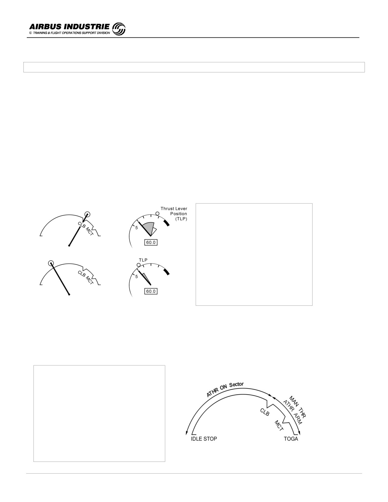
When the ATHR is ON, the thrust lever position determines the MAXIMUM THRUST which can be commanded by the
ATHR when in SPEED or THRUST mode. Thus the thrust levers with ATHR ON act like a thrust limiter or as a thrust
rating panel.
The thrust levers are not BACK DRIVEN by the ATHR computer; they are positioned by the pilot in a specific detent on
the thrust lever range.
The monitoring cues of the ATHR system are THE REAL ENERGY CUES of the A/C:
- Speed, acceleration or deceleration
materialized by the speed trend
vector.
- N1 and N1 command on N1 gauge.
Thrust lever position (TLP)
determines maximum Thrust for
ATHR
In other words the thrust lever position is NOT a monitoring cue of the proper functioning of the ATHR; with a
conventional Autothrottle, thrust lever position should Not be either considered as a cue since in many hazardous
cases, the thrust lever position is misleading (Eng fail, thrust lever jammed …).
!
How to use it?
In ALL ENGINE OPERATIVE situation.
The ATHR may be ON, only when the
thrust levers are in between IDLE STOP
and CLB detent.
When thrust levers are BEYOND the CLB
detent, the thrust is controlled MANUALLY
to the thrust lever position and the ATHR is
armed.
DATE: JAN 2001
Page 113
UDY0102
A320 INSTRUCTOR SUPPORT
NORMAL OPERATION
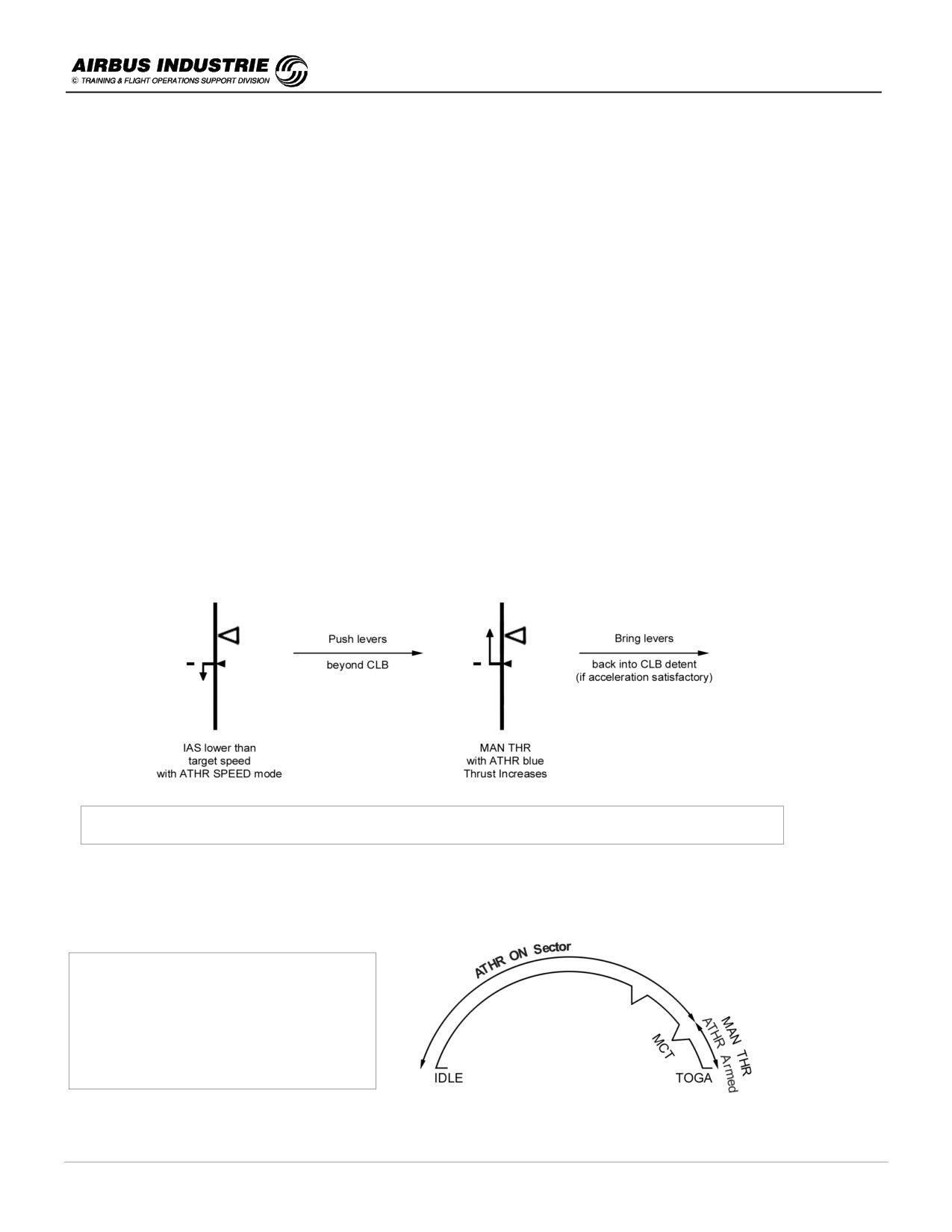
ATHR armed means that the ATHR is ready to be back ON, when the pilot sets the thrust levers back into the CLB
detent (or below). ATHR is displayed blue in the FMA.
At T/O the thrust levers are set either full forward to TOGA or in the FLX detent; the thrust is controlled manually to the
thrust lever position, and the ATHR is armed; thus it is indicated blue on FMA.
After T/O when reaching the THR RED ALT, the thrust levers are set back by the crew in the CLB detent, which sets
the ATHR ON. MAX CLB will therefore be the maximum normal thrust setting, which will be commanded by the ATHR
in CLB, CRZ or DES and APPR if required.
If one thrust lever is set BELOW CLB detent, the FMA outputs a message LVR ASYM to remind this fact to the crew
(e.g. this configuration might be required by a high vibration level on one engine).
But if ALL thrust levers are set BELOW CLB detent with ATHR ON, then a REPETITIVE ECAM CAUTION is triggered,
because there is NO OPERATIONAL REASON to be in that situation, and to limit the ATHR authority on all the
engines, permanently:
➔ AUTO FLT AUTOTHRUST LIMITED caution comes up on ECAM.
In such a case,
➔ either bring all thrust levers back into CLB detent
➔ or set ATHR OFF.
If you set all thrust levers BEYOND CLB detent while the ATHR is ON, you control the thrust manually to the thrust
lever position. FMA displays MAN THR white and ATHR gets armed. LVR CLB flashes on FMA as a reminder. This
technique is most efficient when the A/C speed drops significantly below the target.
Once you are satisfied with the A/C speed or acceleration, bring the thrust levers back into CLB detent. ATHR is back
ON.
Speed drop in approach - Recommended Recovery Technique
NOTE:
When you use this technique during approach, to regain VAPP for example, move the thrust levers forward of CLB
detent but don't go beyond MCT. Indeed, in most cases it is useless and you risk hitting the TOGA stop which will
engage the Go Around mode.
In EO Situation:
Exactly the same principles apply, except
that ATHR may be ON only when the
trust levers are set between IDLE STOP
and MCT.
WITH ONE ENGINE INOPERATIVE
In case of EO, the levers will be in MCT detent, throughout the rest of the flight, because MCT is the maximum thrust,
which may be normally commanded by the ATHR for climb or acceleration through all flight phases such as CLB, CRZ,
DES, APPR.
DATE: JAN 2001
Page 114
UDY0102
A320 INSTRUCTOR SUPPORT
NORMAL OPERATION
Set ATHR OFF
ATHR may be set OFF either by pressing the I/D on the thrust levers or by pressing the ATHR P/B on the FCU, or by
bringing all thrust levers back to Idle.
The normal procedure to set ATHR OFF is to press the I/D:
-
If this is done without precautions while the thrust levers are in CLB detent, the thrust will increase to MAX CLB
thrust. This may cause an undesired thrust change: e.g. during approach, the ATHR, being in SPEED mode,
commands N1 around 55 %. If the pilot presses the I/D, the ATHR is set OFF and the thrust goes to MAX CLB
which perturbates the approach.
-
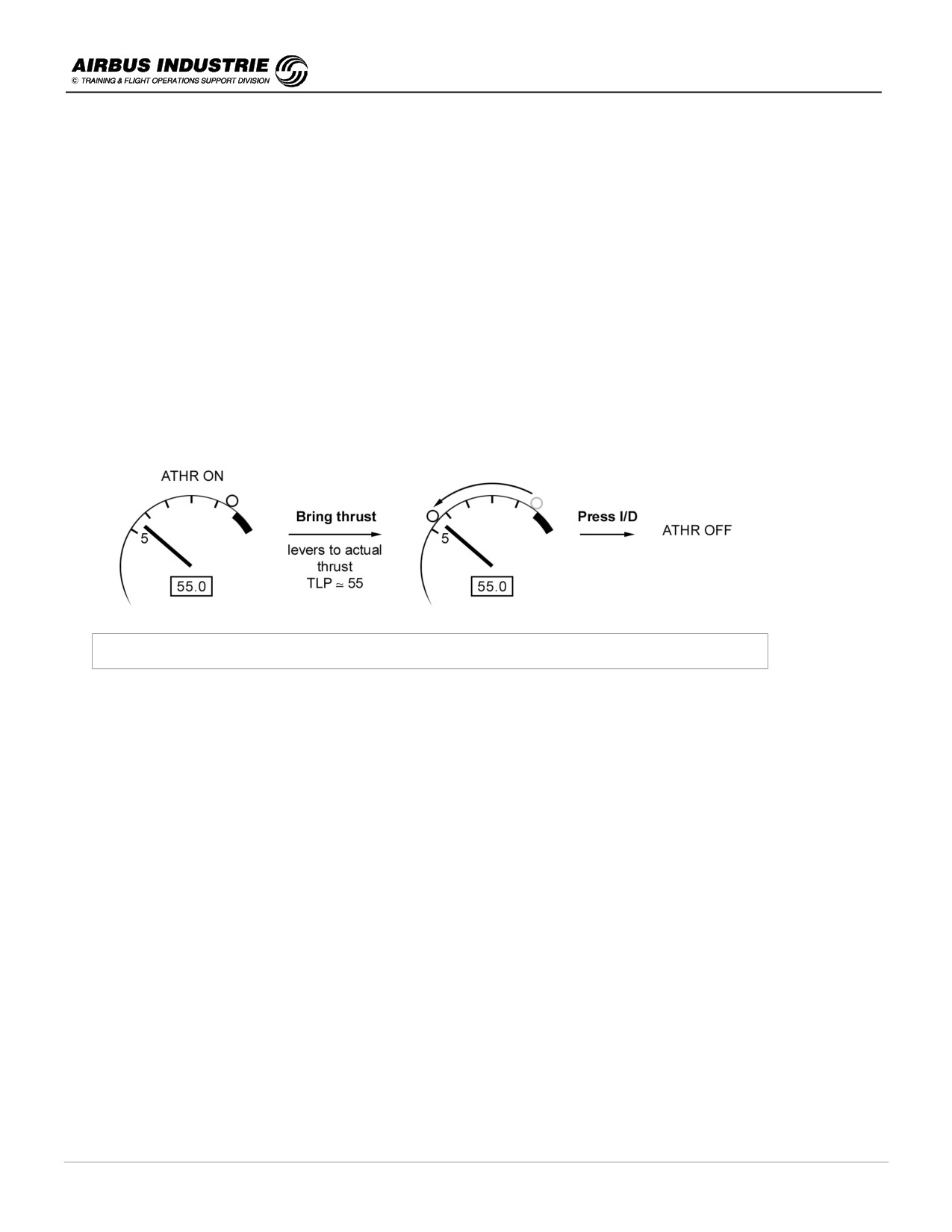
So the recommended technique to set ATHR OFF is:
• bring back thrust levers roughly to the current thrust setting using the TLP symbol on thrust gauge,
• press the I/D.
This technique minimizes the thrust discontinuities, when setting ATHR OFF.
Set ATHR to OFF - Recommended Technique
You may also set ATHR OFF by setting thrust levers back to IDLE stop.
This is commonly used in descent when ATHR is on THR IDLE or at landing. Indeed during the FLARE with ATHR ON,
thrust levers are set in the CLB detent. Thus when thrust reduction is required to land, bring thrust levers to the IDLE
stop smoothly. This action retards the thrust and sets ATHR OFF.
The “RETARD” call out is a reminder to do so; it comes in the flare at 20 ft, except if autoland where it comes at 10 ft.
Note that once thrust levers are set back to idle and ATHR is OFF. You can set it back to ON by pressing the ATHR P/B
on the FCU and bringing back thrust levers into the applicable detent. Don't delay this last action in order to avoid the
ECAM “Autothrust limited” message.
It is NOT recommended to set ATHR OFF with the ATHR P/B located on the FCU.
This is considered as an UNVOLUNTARY ATHR OFF command (as if it was due to a failure - creating an ECAM
action).
DATE: JAN 2001
Page 115
UDY0102
A320 INSTRUCTOR SUPPORT
NORMAL OPERATION
Consequently, the THRUST is frozen and remains LOCKED at the value it had when the pilot has pressed the ATHR
P/B, as long as the thrust levers remain in the CLB or MCT detent. If the pilot moves the thrust levers out of the detent,
the thrust is manually controlled and thus unlocked.
An ECAM caution and FMA message are triggered during thrust lock:
-
THR LK amber on FMA. ECAM caution is:
AUTO FLT ATHR OFF
ENG THR LOCKED
THR LEVERS ……………… MOVE
In that case, whenever you move the thrust levers out of the detent, you recover full manual control and THR LK is
removed from FMA.
Don’t use this feature, unless I/D inoperative.
A FLOOR
When the aircraft AOA increases BEYOND a threshold called ALPHA FLOOR, which means that the A/C has
decelerated a lot (below ALPHA PROT speed), the ATHR is set ON automatically and sends TOGA thrust, regardless
of thrust lever position.
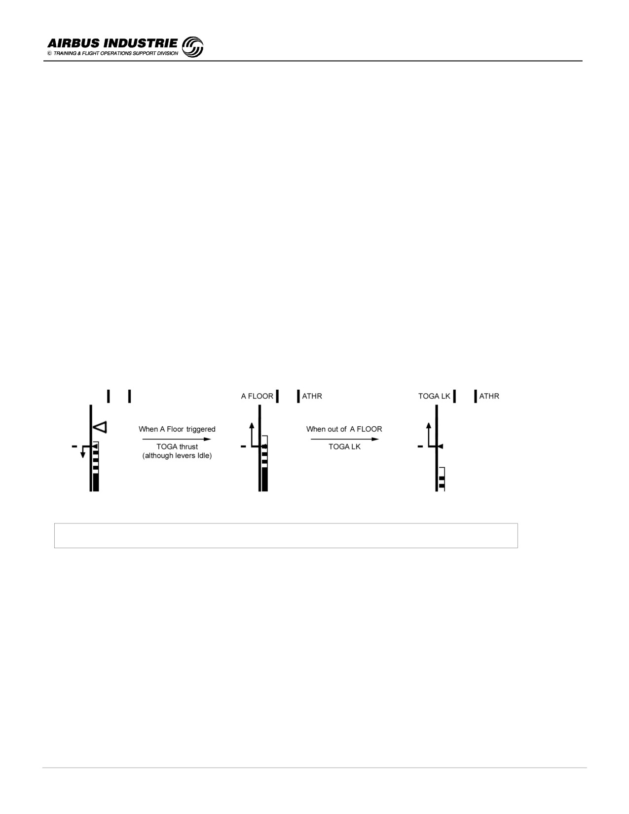
Example:
A/C in descent with the thrust levers manually set at IDLE. Suppose that the A/C decelerates, while hand flying with FD
OFF as indicated on FMA:
Speed scale and FMA indications in a typical A.FLOOR case
When the speed decreases so that AOA reaches the ALPHA FLOOR threshold, ATHR engages and sends TOGA
thrust despite the fact that the thrust levers are in Idle position.
Suppose that now the A/C re-accelerates.
When the speed increases so that the AOA gets below the ALPHA FLOOR threshold, TOGA thrust is maintained or
locked in order to allow the pilot to reduce the thrust when he JUDGES it to be necessary.
-
FMA displays TOGA LK, meaning that TOGA thrust is locked.
-
The only way to recover the desired thrust is to set ATHR OFF using the I/D.
-
A FLOOR is available when FBW is in NORMAL LAW from lift off to 100 ft R/A at landing. It is inhibited if one
engine is unserviceable.
DATE: JAN 2001
Page 116
UDY0102
A320 INSTRUCTOR SUPPORT
NORMAL OPERATION
!
When to use ATHR ?
-
ATHR is recommended throughout the flight. It may be used in most failures cases such as:
• Engine failure including autoland and
• Abnormal configurations.
-
At take off, set thrust levers to FLX/TOGA as required.
The thrust is then manually controlled and ATHR is armed (e.g. MAN TOGA).
-
At THR RED ALT, set thrust levers to CLB detent. ATHR is ON and operates in a mode, THR or SPEED,
associated to AP/FD vertical mode.
You may keep the ATHR ON throughout the flight.
-
During APPROACH, hold the thrust levers. Whenever additional thrust is required, push on the levers, not
exceeding MCT detent. MAN THR is on FMA and thrust increases.
When enough acceleration is obtained, bring the thrust levers back into CLB notch. ATHR is back ON. Keep
hands on levers.
-
FLARE and LANDING
When thrust retardation is required, bring the thrust levers smoothly to IDLE stop. ATHR is then OFF.
The “RETARD” call out comes up as a reminder as long as levers are above idle.
-
FOR GO AROUND
Set all thrust levers to TOGA. The thrust is manually controlled to TOGA; MAN TOGA on FMA, ATHR is
armed.
Additionally SRS / GA TRK modes engage, Go Around phase activates and Missed Approach + previously
flown approach become the active F.PLN.
In case of a Go Around at low weight, or at a higher height, once TOGA is set and the A/C is established in
pitch, you may consider to set the thrust levers back into MCT or CLB detent if very high climb performance is
achieved.
-
ENGINE FAILURE
Set LIVE engine thrust lever to MCT as per FMA LVR MCT message and ECAM caution.
-
MONITOR ATHR with: FMA - SPEED / SPEED TREND on PFD - N1/N1 command (EPR) on ECAM E/W-D.
NOTE:
During approach the ATHR operates in SPEED mode. There is NO automatic RETARD except in AUTOLAND.
This explains why the RETARD call out comes at 20 ft in all cases, except AUTOLAND where it comes at 10 ft.
DATE: JAN 2001
Page 117
UDY0102
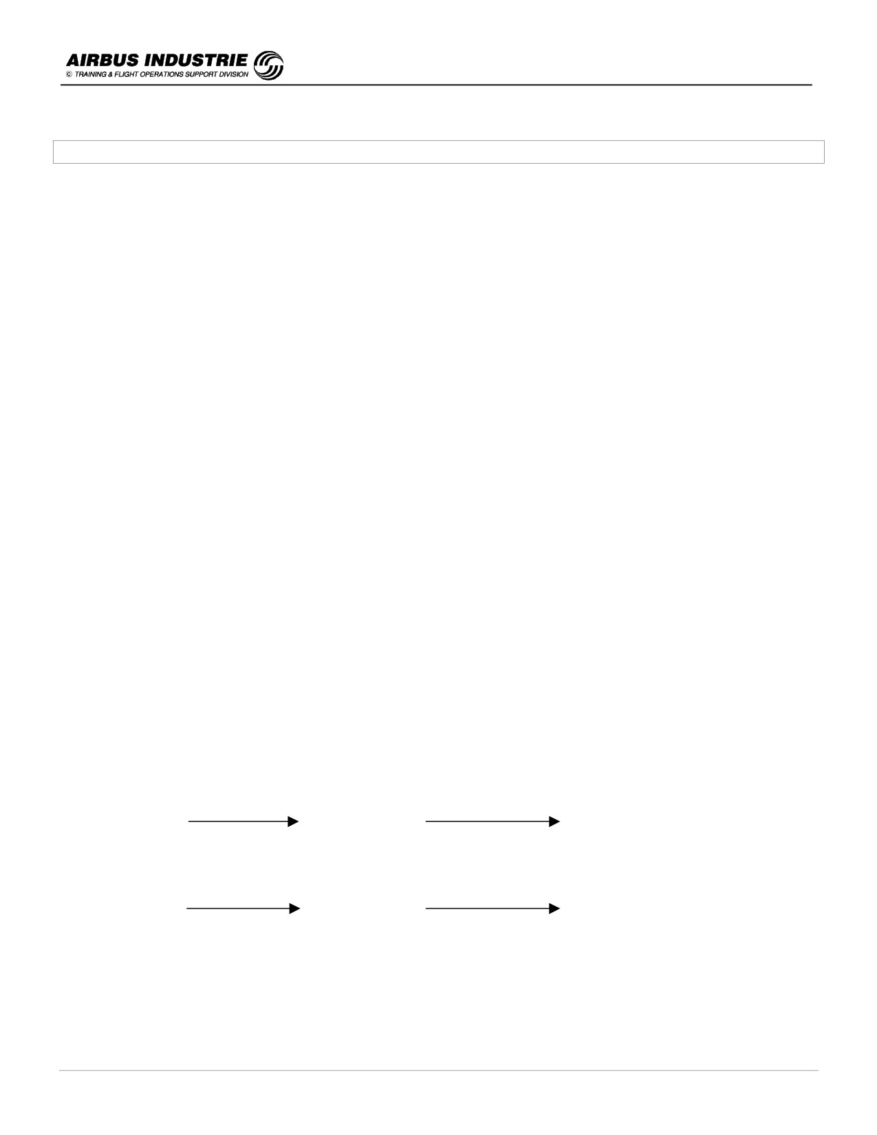
A320 INSTRUCTOR SUPPORT
NORMAL OPERATION
22 - FLIGHT DIRECTOR / AUTOPILOT / ATHR - MODE CHANGES AND REVERSIONS
!
Mode Change / Reversion Objectives
AP/FD and ATHR operate in given modes. The choice of a mode is a strategic decision of the pilot.
The modes are therefore manually engaged by the pilot; but they may change automatically as per built in logics
dictated by:
-
the integration of AP/FD/ATHR,
-
the integration of FMS within AP/FD/ATHR,
-
the logical sequence of modes and
-
the so called « mode » reversions.
The integration of AP / FD / ATHR follows the logic, the pilots apply, to control the aircraft. Indeed, there is:
A DIRECT RELATION BETWEEN A/C PITCH CONTROL and ENG THRUST CONTROL in order
-
to manage the A/C energy,
-
if AP/FD pitch mode controls a vertical trajectory (e.g. ALT, V/S, FPA, G/S etc.),
➥ the ATHR controls a SPEED,
-
if AP/FD pitch mode controls a speed (e.g. OP CLB, OP DES etc.),
➥ the ATHR controls a THRUST (THR CLB, THR IDLE)
-
if NO AP/FD pitch mode - i.e. AP OFF and FD OFF,
➥ the ATHR controls a SPEED.
Thus, when there is an AP/FD pitch mode change, there is an associated ATHR mode change.
NOTE:
This explains why on FMA, the ATHR mode and the AP/FD vertical mode columns are adjacent.
The logical sequence of modes:
-
It is
« normal » for an A/C to climb towards a given altitude; thus it is logical that if a pilot selects a V/S mode
towards a target altitude, or if he wishes to climb towards a target altitude in OP CLB, the AP/FD provides the order
to climb, capture and then track this altitude.
Thus when you engage those modes you will simultaneously and automatically ARM the NEXT LOGICAL mode.
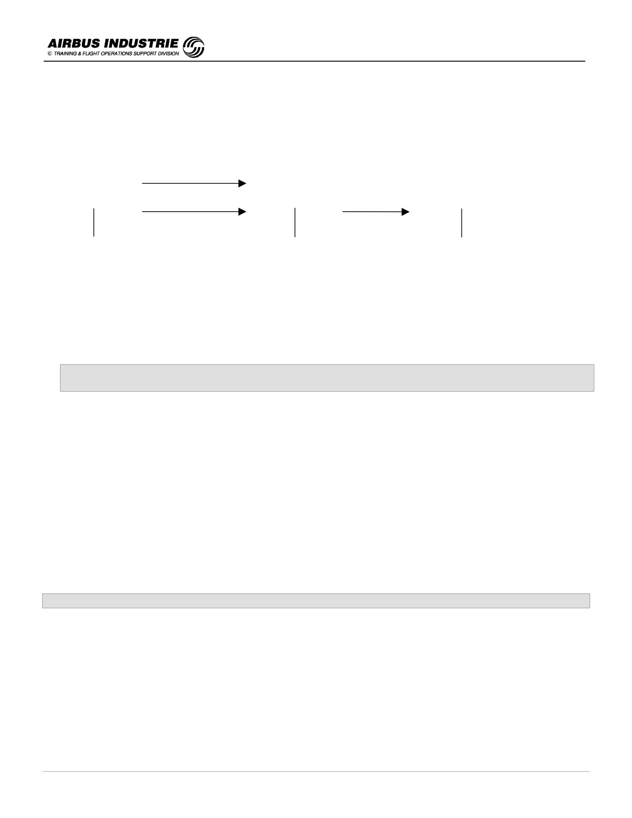
For example:
V/S + 2000
ALT *
ALT
ALT
Capture conditions
Tracking conditions
OP CLB
ALT *
ALT
ALT
The modes then change sequentially.
DATE: JAN 2001
Page 118
UDY0102
A320 INSTRUCTOR SUPPORT
NORMAL OPERATION
-
The pilot may also in some cases ARM himself a mode in advance, because he wishes the AP/FD to intercept
a given trajectory.
Typically NAV, LOC - G/S, APPNAV - FINAL may be ARMED by the pilot.
When the capture or tracking conditions occur, then the modes will change sequentially: e.g.
HDG
NAV
NAV
ALT
HDG
ALT
LOC *
ALT
LOC
G/S
LOC
G/S
G/S
etc.
As a summary, such LOGICAL MODE CHANGES occur when modes are ARMED and indicated BLUE on PFD.
The integration of FMS within AP/FD/ATHR
When a pilot has defined a FPLN, the FMS considers this FPLN as a WHOLE, that is LATERAL + VERTICAL FPLN.
Consequently the FG will guide the A/C along the FPLN as a WHOLE, that is:
-
along the LAT FPLN (NAV - APP NAV modes) and
-
along the VERT FPLN (CLB - DES - FINAL modes).
Vertical Managed modes can only be used,
if Lateral Managed NAV mode is used.
But if the pilot elects to fly away from the lateral FPLN, the FG will no longer guide along the vertical FPLN.
Thus, if for example:
-
HDG (TRK) mode is selected, while NAV is engaged along with CLB or DES modes, then CLB/DES mode will
disengage and a mode reversion will occur.
The mode reversions
The mode reversions are automatic mode changes which occur somehow unexpectedly, but which ensure a
COHERENT AP/FD/ATHR operation following pilot interventions:
-
the pilot CHANGES the FCU ALT TARGET in specific conditions,
-
the pilot ENGAGES a mode on ONE AXIS which automatically DISENGAGES the associated mode on the
OTHER AXIS and
-
the pilot HANDFLIES the A/C with FD ON, but does NOT follow the FD ORDERS thus leading the A/C to the
border of the Flight Envelope.
In all those cases a MODE CHANGE or REVERSION WILL OCCUR.
DATE: JAN 2001
Page 119
UDY0102
A320 INSTRUCTOR SUPPORT
NORMAL OPERATION
!
MODE REVERSION MECHANIZATION
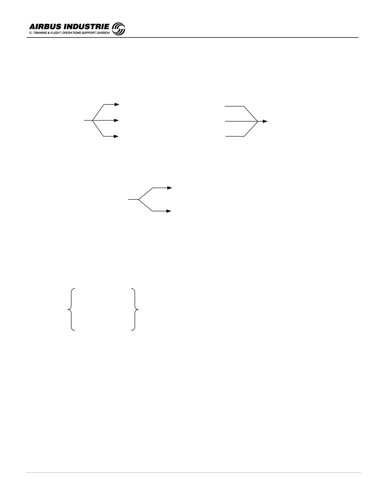
A. The pilot CHANGES the FCU ALT TARGET making the active VERTICAL MODE impossible:
DOWN, while OPCLB (CLB)
FCU ALT change
while ALT*
V/S (FPA)
UP, while OPDES (DES)
This reversion to V/S (FPA) mode on current V/S target, does not modify the PITCH behavior of the A/C. It leaves it to
the pilot to change it as required.
B. The pilot engages a mode on one axis, which DISENGAGES the ASSOCIATED mode on the OTHER AXIS.
LOC - G/S
This happens in 2 cases
OF COMMON MODES
NAV - CLB or DES
APPNAV - FINAL
The logic is as follows:
In CLIMB:
If CLB/NAV are engaged and then if HDG or TRK mode is selected
⇒ CLB reverts to OP CLB
In DES:
DES/NAV or,
If
FINAL APPR or
are engaged and then if HDG or TRK mode is
selected
LOC - G/S
⇒ DES or FINAL or G/S revert to V/S.
This reversion does not modify the PITCH behavior of the A/C.
It leaves it to the pilot to decide what to do next, according to circumstances.
Note that HDG may be either manually selected by the pilot, or automatically in case NAV is engaged and the A/C flies
into a LAT FPLN DISCONTINUITY (LAT DISCONT AHEAD message).
NOTE:
In case of LOC - G/S or FINAL APPR modes, if V/S (FPA) is selected, the lateral mode reverts to HDG (TRK).
DATE: JAN 2001
Page 120
UDY0102
A320 INSTRUCTOR SUPPORT
NORMAL OPERATION
C. The pilot hand flies the A/C with FD ON, and does NOT follow the FD PITCH ORDERS
This reversion is an ATHR MODE REVERSION effective when the ATHR is in THRUST MODE (THR IDLE, THR CLB)
and the A/C reaches the BORDERS of the SPEED ENVELOPE (VLS, VMAX), because the pilot does not handfly the
FD pitch orders:
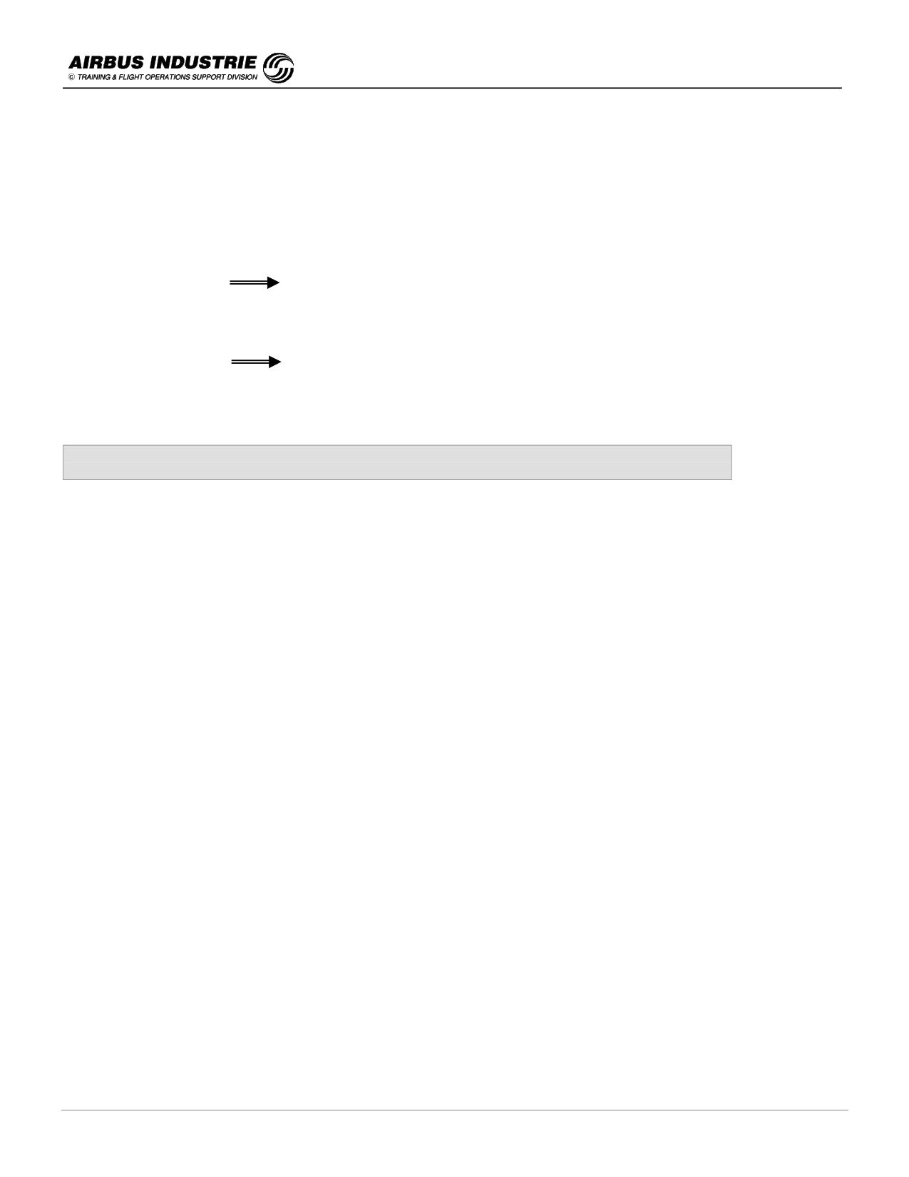
-
If | THR IDLE | OPEN DES (DES) | and the pilot pitches the aircraft Up, the speed decreases.
Reaching VLS
ATHR REVERTS TO SPEED MODE.
-
If | THR CLB | OPEN CLB (CLB) | and the pilot pitches the aircraft DOWN, the speed will increase.
Reaching VMAX
ATHR REVERTS TO SPEED MODE.
The ATHR in SPEED mode automatically readjusts the thrust to regain the target speed.
On latest aircraft versions, FD bars are REMOVED, since they are NOT FOLLOWED by the crew.
THE MODE REVERSIONS, which are sometimes unexpected, are an ADDITIONAL REASON TO
PROPERLY MONITOR THE FMA.
DATE: JAN 2001
Page 121
UDY0102
A320 INSTRUCTOR SUPPORT
NORMAL OPERATION
23 - FMS NAVIGATION ACCURACY - CROSSCHECK, POSITION UPDATE, GPS
!
General
The FIRST and ESSENTIAL function of the FMS is NAVIGATION; which is to compute the FMS position as accurately
as possible.
The validity of all the other FMS functions depends upon the accuracy of the FMS position.
Furthermore, the ACCURACY of the FMS position dictates the strategy which the pilot will apply in the use of Autopilot
/ Flight Director modes as well as on the type of display to be used on the ND.
Auto Pilot / Flight Director modes (managed or selected).
FMS NAV ACCY →
ND modes (Arc - Rose NAV / Rose VOR - ILS, raw data).
EGPWS (ON/OFF).
FMS NAV ACCY check is a Periodic Drill
to be achieved throughout the flight.
!
Reminder of key points in aircraft position computation
Without GPS Primary
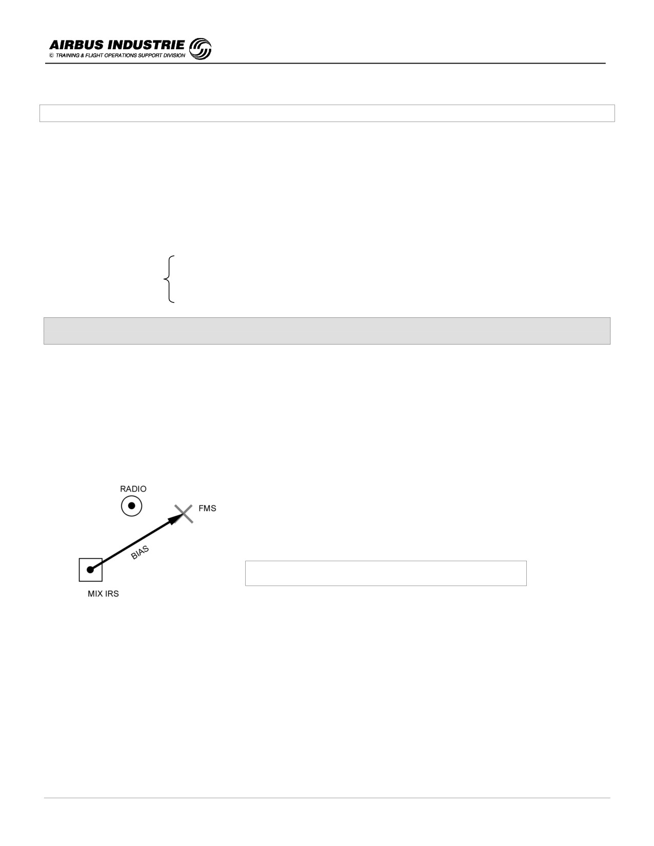
The FMS position is derived from the 3 IRS positions which are blended into a MIX IRS position and from a RADIO
position whenever 2 DMEs, or a VOR/DME, or a GPS supplemental are available. The GPS supplemental is
considered as an additional kind of navaid; it is accepted if it falls within a circle around the radio or the MIX IRS
position.
When a RADIO position is available, the FMS position tends towards the Radio position.
FMGS Position Calculation Principle
Hence the FMS continuously computes:
-
the FMS position out of MIX IRS and RADIO positions,
-
the BIAS between MIX IRS and FMS position, so as to benefit from the latest update when the RADIO position
becomes unavailable and
-
the ESTIMATED POSITION ERROR (EPE) of its own position.
The ESTIMATED POSITION ERROR (EPE) is an ESTIMATE; this means that the FMS considers the instantaneously
available navigation means used in the elaboration of the FMS position, applies specified tolerances to each one of
them and processes the EPE. Those tolerances assume that the navigation means work properly; but they ignore
possible excessive drifts of the IRSs, or erroneous locations of navaids within the Nav Data Base, for example.
DATE: JAN 2001
Page 122
UDY0102

A320 INSTRUCTOR SUPPORT
NORMAL OPERATION
Consequently the HIGH / LOW accuracy information provided on PROG page are INDICATORS to the crew of the
POTENTIAL ACCY of the FMS position versus a specified accuracy criteria.
The EPE is an ESTIMATE.
HIGH/LOW and thus NAV ACCY UPGRADED/DNGRADED messages are merely
INDICATORS to the crew of the estimated accuracy of the FMS position
versus required criteria.
With GPS Primary
-
The GPS directly interfaces with the IRSs which output a GPIRS position.
When a GPIRS position is available, it supersedes the RADIO position if available, so that the FMS position tends
to the GPIRS position.
The GPS provides 2 essential data, additionally to position (Lat/Long/Alt):
-
The ACCURACY of the Lat/Long position: it is a direct function of the satellite constellation in view of the aircraft. If
the satellites are low on the horizon, or if their respective position is unfavorable, the resulting accuracy will be
poor. It is provided as a "Figure of Merit".
This accuracy can be computed with a high probability of confidence.
-
The INTEGRITY, which is a direct function of the number of satellites in view of the aircraft, allows a defectuous or
erroneous satellite to be rejected. If 5 or more satellites are in view, several combinations of those satellite signals
may be used to process “several positions” and to carry out reasonableness tests on the satellite signals
themselves.
Therefore if the GPS position (or GPIRS position) fullfills the INTEGRITY and ACCURACY criteria, this means that this
position is the BEST RAW DATA position available.
GPS PRIMARY = ACCURACY + INTEGRITY CRITERIA met ➾ GPIRS = RAW DATA
!
Some details on the information provided:
PROG Page:
-
Indicates GPS PRIMARY.
-
Indicates the value of the Estimated Navigation Accuracy in green. It is either the one as computed by the GPS
when GPS PRIMARY is available, or the EPE when GPS PRIMARY is LOST.
-
Indicates the Required Navigation Accuracy in blue. To day it is either the Navigation accuracy criteria as required
in cruise, TMA or approach area, or it can be manually inserted.
-
If the Estimated Nav Accy is less than the Required Nav Accy, HIGH accuracy is displayed (or LOW if vice versa).
These indications will allow the RNP concept (required nav performance) linked to FANS to be addressed.
NOTE:
RNP is equivalent to required navigation accuracy.
DATE: JAN 2001
Page 123
UDY0102
A320 INSTRUCTOR SUPPORT
NORMAL OPERATION
SELECTED Navaid page:
DESELECT GPS prompt:
-
it is provided in order to allow the crew to prevent the FMS from using the GPS data for position computation,
should a major problem occur with GPS. GPS PRIMARY LOST message is then displayed on MCDU and ND.
The GPS can be reselected later on the same page.
GPS PRIMARY prediction page:
-
GPS PRIMARY allows the crew to carry out approaches down to MDA 250 ft AGL.
GPS PRIMARY criteria (INTEGRITY + ACCURACY) depends upon the SATELLITE CONSTELLATION status at a
given time, in a given location; this is predictable (ephemerides).
Therefore, it is most valuable for crews to know if GPS PRIMARY will be available at DESTINATION, or at ALTN.
This information is provided on GPS PRED page when the A/C is fitted with IRS Honeywell.
ND / MCDU messages:
-
GPS PRIMARY- When GPS PRIMARY is again available. This message is clearable.
GPS PRIMARY LOST: when GPS PRIMARY is lost. Clearable on MCDU but not on ND.
!
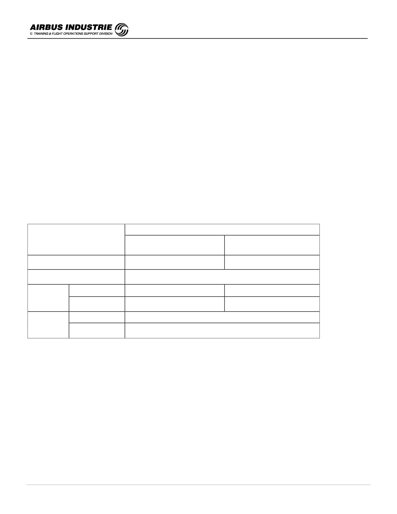
Summary
FMS POSITION
FLIGHT PHASE
WITHOUT GPS PRIMARY
GPS PRIMARY
(no GPS or GPS suplemental)
On ground before T/O
MIX IRS
GP IRS
T/O
Updated at runway threshold (shift)
With Navaids
Tends to RADIO
GP IRS
GPS
AVAIL
Without Navaids
MIX IRS + BIAS
GP IRS
GPS
With Navaids
Tends to RADIO
PRIM
Without Navaids
MIX IRS + BIAS
LOST
NOTE:
When GPS is supplemental (hybrid function), it is considered as a navaid, thus it is part of the Radio Position.
NOTE:
FMS/GPS POSITION DISAGREE message comes up from time to time when [FM - GPS] ≥ 0.5 NM in LAT or LONG.
This occurs due to different reference co-ordinates being used in New Data Base, in T/O or LOC update cases.
DATE: JAN 2001
Page 124
UDY0102
A320 INSTRUCTOR SUPPORT
NORMAL OPERATION
!
Operational Consequences
General rules:
-
Use HIGH / LOW as INDICATORS.
-
Periodically CROSSCHECK NAV ACCY. Once in climb, every 45 mn in cruise and before TOD, reaching TMA and
IAF, and whenever a navigation doubt occurs.
-
Use NAV ACCY DNGRADED message as an indication to crosscheck the navigation accuracy.
➔ If GPS is PRIMARY, crosscheck is not necessary.
➔ If GPS PRIMARY is LOST, crosscheck is necessary.
Consequences of the crosscheck:
-
The result of the NAV ACCY crosscheck determines the operational consequences. It is not the role of NAV ACCY
UP/DN GRADED messages or HIGH/LOW indications which are merely indicators, and must be used to trigger a
crosscheck.
-
The operational consequences of the nav accy crosscheck are:
If the crosscheck is POSITIVE or GPS is PRIMARY:
• AP/FD Lateral / Vertical Managed modes MAY BE USED,
• ND ARC and ROSE NAV modes ARE USED by both PF & PNF with needles, when required and
• EGPWS is set to ON.
If the crosscheck is NEGATIVE:
• AP/FD Lateral / Vertical Managed modes may be used WITH CARE except in Approach where selected
modes have to be used.
• ND ARC and ROSE NAV may be used WITH CARE and WITH RAW DATA by PF and PNF except in
approach where PF has to refer to raw data systematically.
• Be prepared to switch to selected modes and to ROSE VOR/ILS, if you have a doubt.
• EGPWS must be set to OFF.
NOTE:
Whenever a doubt arises, revert to selected modes and raw data only, to avoid any confusion. On the other hand one
must be aware that, in cruise for example, if no navaid available and no GPS primary, the EPE continuously rises
without any damageable consequence. The FMS position slowly drifts along with the drift of the IRSs, while its position
is affected by the latest determined bias.
DATE: JAN 2001
Page 125
UDY0102
A320 INSTRUCTOR SUPPORT
NORMAL OPERATION
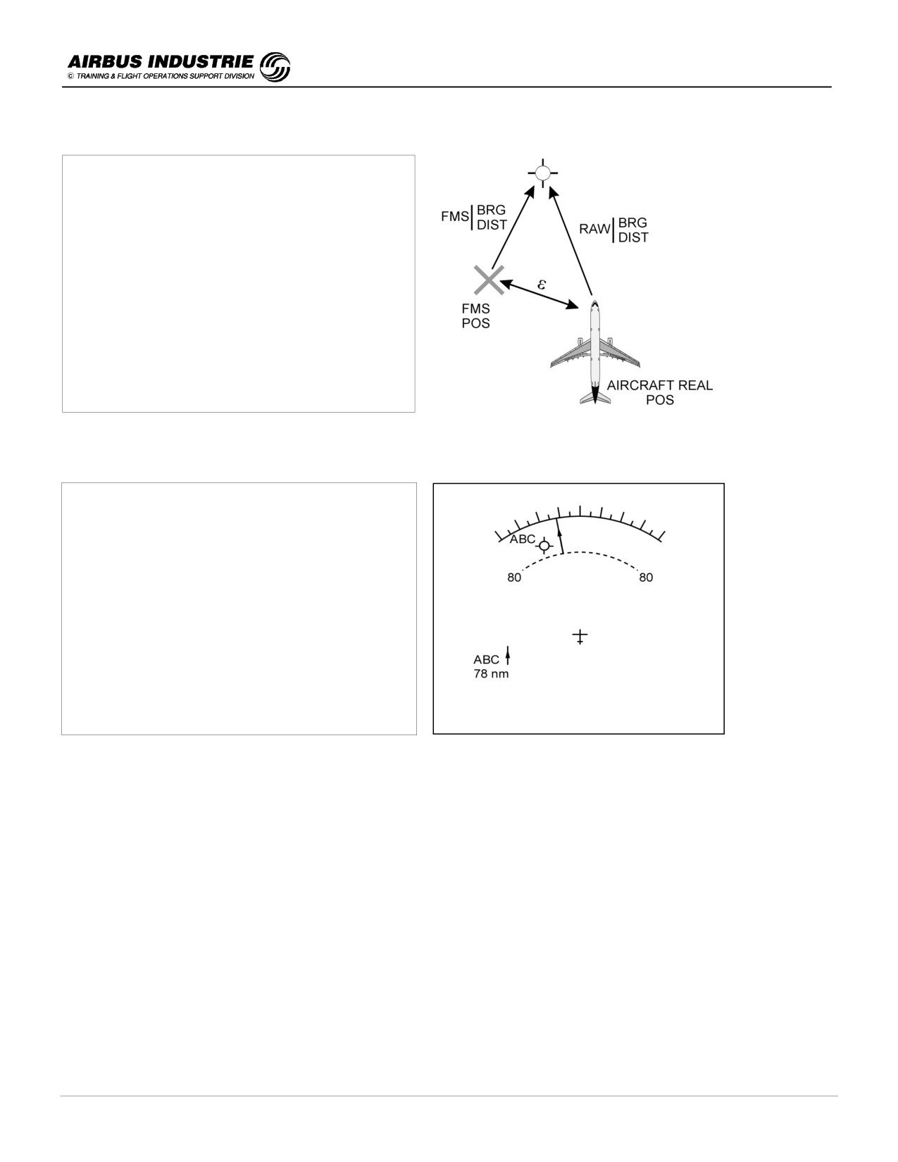
Navigation accuracy crosscheck technique:
The principle consists in comparing the
Bearing/Distance:
- as calculated by the FMS position and given
navaid stored in the FMS data base,
- as directly provided by the Raw Data received
from the navaid which materializes the relative
position of the aircraft with the navaid.
The difference allows the error [ε] to be quantified.
-
Technique used in the various flight phases:
En Route:
- On ND use the relative position of the pointer
with the navaid symbol and the DME distance
versus the distance to the navaid symbol
materialized by the range markers. This allows a
quick visual nav accy crosscheck. Possibly use
RADAR MAP image when flying over oceans
and reaching islands or a coast line.
FMS NAV ACCY
cross check principle
Note:
It is also possible to use raw data provided on the DDRMI, which is associated to the tuned navaid on RAD NAV page,
to compare with FM computed data by entering VOR name on PROG page (BRG/DIST TO).
-
In Descent, TMA and approach:
• insert destination or arrival VOR/DME ident on NAVAID and on PROG pages (BRG/DIST field) on PF side and
• compare DME and Needle Bearing on ND, to BRG/DIST on PROG page and determine the difference.
DATE: JAN 2001
Page 126
UDY0102
A320 INSTRUCTOR SUPPORT
NORMAL OPERATION
Strategy in Non Precision Approach:
- A Non Precision Approach is flown using AP/FD managed modes and ND ARC or ROSE NAV, display modes only
if the FMS NAV ACCY crosscheck is POSITIVE or GPS is PRIMARY.
• In case of no GPS available, the reference navaid raw data of the NPA must be displayed, at least on PF side.
[e.g. VOR/DME approach. The VOR/DME raw data (pointer + DME) must be selected on PF side].
• In case of GPS PRIMARY, this is not compulsory.
-
In case the NAV ACCY DNGRADED msg comes up, proceed immediately with a NAV ACCY CROSS CHECK:
• if POSITIVE, continue as before and
• if NEGATIVE, revert to SELECTED MODES, and SELECT ROSE VOR at least on PF side.
-
In case of GPS PRIMARY, two types of approaches are flown:
• the NPA defined with a VOR, VOR/DME, TAC, ADF… (also called overlay approaches):
➔ although not compulsory, it is recommended to select the associated needles on the ND.
➔ in case GPS PRIMARY LOST msg comes up, proceed immediately with a NAV ACCY CROSS CHECK
and adapt your strategy as if no GPS is available.
• The NPA is a GPS defined approach:
➔ the raw data is the FMS position and
➔ in case GPS PRIMARY LOST msg comes up, the approach must be interrupted.
!
Position Update on PROG page
This function is to be used EXCEPTIONALLY in case a MAJOR MAPSHIFT occurs, or in case of an obvious major
position error, noticed by specific messages such as CHECK A/C POSITION, FM1/FM2 POS MISMATCH…
After having analyzed the situation, the UPDATE will be decided or not.
The RECOMMENDED TECHNIQUE is to carry out an UPDATE OVER a beacon by pressing the UPDATE prompt
once, estimating that the A/C overflies the beacon, using the associated needle.
The potential induced error at FL390 is approximately 4 to 5 NM. When a position update is achieved, the EPE is
automatically set to a higher value, and Navigation Accuracy is Low.
However this update will allow the FMS to resume its normal navigation function.
DATE: JAN 2001
Page 127
UDY0102
A320 INSTRUCTOR SUPPORT
NORMAL OPERATION
NOTE:
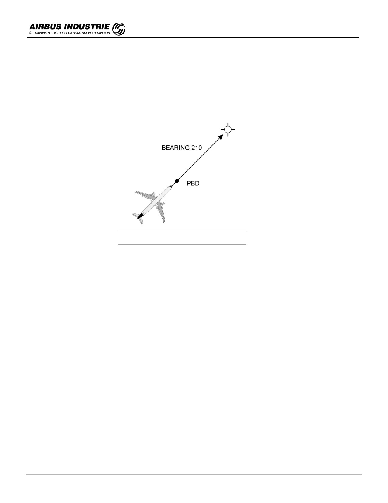
Another technique which may be used WITH CARE is to update on a BRG/DIST from the beacon. Insert P/B/D in the
update field and when you reach it, press UPDATE.
The potential induced error is by far lower when DIST is over 60 NM.
Be careful with the bearing value you insert. Be aware that you have to insert a BEARING (do not make a 180° error).
Exceptional position update technique
DATE: JAN 2001
Page 128
UDY0102

A320 INSTRUCTOR SUPPORT
NORMAL OPERATION
24 - FLIGHT CONTROLS - HIGHLIGHTS ON HANDLING CHARACTERISTICS
The relation between the pilot input on the stick and the aircraft response is called the CONTROL LAW which
determines the HANDLING CHARACTERISTICS of the A/C.
The Fly by wire system accommodates for 3 sets of control laws depending upon the integrity and redundancy status
of the computers, peripherals and of hydraulic generation. These 3 sets are: NORMAL LAW - ALTERNATE LAW -
DIRECT LAW.
!
Normal Law
The Normal Law is most commonly available and accomodates single failures.
The handling characteristics of the normal law within normal flight envelope are:
-
the aircraft is STABLE and MANEUVERABLE,
regardless of A/C IAS,
-
same response is obtained from the aircraft consistently,
Altitude, GW and CG.
-
the efforts on stick are balanced in pitch and roll.
The handling characteristics of the normal law at the border of the flight envelope are:
-
full authority given to the pilot to achieve Maximum Performance of the A/C,
-
allow an instinctive / immediate reaction from the pilot in emergency and
-
reduce the potential to overcontrol / overstress the aircraft.
In general, when the pilot acts on the stick, he directly orders an aircraft response (pitch or roll rate, or…). Thus the
aircraft directly achieves the pilot orders; there is no longer a need to “bracket” on the stick as on a non fly by wire
aircraft where the pilot had to continuously adjust the stick and trim so as to get the desired aircraft behaviour.
CHARACTERISTICS IN PITCH
When acting on the stick the pilot commands a constant G load maneuver and the aircraft response is G Load / Pitch
rate. The pilot order is therefore consistent with the aircraft response “naturally” expected by the pilot, Pitch rate at low
speed / Flight Path rate or G at high speed.
Hence STICK FREE, the A/C maintains the flight path even in case of speed changes. Furthermore, STICK FREE in
case of Configuration changes, or thrust variations, etc… the pitching moment effects are reduced by the feedbacks in
the control law itself and compensated for by precommands. With STICK FREE in turbulence, small deviations do
occur on the flight path but with a tendancy of the A/C to regain a steady condition.
As a consequence the A/C is a STABLE PLATFORM and AUTOTRIMMED; it needs to be flown with minor corrections
from the pilot on the stick, when the A/C deviates from its intended flight path.
Don’t fight with the stick; if you feel you overcontrol, release the stick.
The pitch law as described here above is NOT best suited for TAKE OFF and FLARE, where stable flight path is NOT
what the pilot naturally expects.
DATE: JAN 2001
Page 129
UDY0102
A320 INSTRUCTOR SUPPORT
NORMAL OPERATION
Hence the computers adapt AUTOMATICALLY the control laws to the flight phases, transparently to the pilot:
GROUND LAW
➔ the control law is DIRECT law and
FLARE LAW,
➔ the control law is PITCH law.
As a consequence, those maneuvers are achieved most naturally. The Flare, for example, requires a permanent AFT
pressure on the stick from the pilot to achieve a progressive flare, and the derotation consists in smoothly flying the
NLG down with a small aft pressure on the stick.
LATERAL CHARACTERISTICS
When acting laterally on the stick, the pilot orders and gets, most naturally, a ROLL RATE.
Hence STICK FREE, he orders 0 roll rate; thus the current bank angle is maintained within ± 33°.
As a consequence, the A/C is LATERALLY STABLE and NO AILERON TRIM is required.
But the lateral law is also a mixture of ROLL and YAW demand with:
-
Automatic Turn coordination,
-
Automatic Yaw damping and
-
Yaw damper initial response to a major aircraft assymetry.
During a Normal Turn (bank within ± 33°), in level flight:
-
move the stick laterally only since there is pitch compensation in turn,
-
the more you move the stick laterally, the greater the resulting roll rate (e.g. 15°/sec at max deflection) and
-
you don’t need to use the rudder.
In case of Steep Turns (bank angle greater than 33°), you have to hold a lateral pressure on the stick to keep the bank
and an aft pressure on the stick to keep level flight.
Indeed spiral stability is reintroduced and pitch compensation is suppressed beyond 33°, since there is no operational
reason to fly with such high bank angles for a lengthy period of time in normal circumstances.
REACTION TO ENGINE FAILURE
If an engine failure occurs and the pilot maintains stick free, the natural tendency of the A/C to roll and yaw is
CONTAINED by the lateral normal law.
STICK FREE, the A/C will reach approximately 5° constant bank, a constant side slip, and a slowly diverging heading
rate.
DATE: JAN 2001
Page 130
UDY0102
A320 INSTRUCTOR SUPPORT
NORMAL OPERATION
The lateral behaviour of A/C is quite safe !
But the pilot is then the BEST to adapt the lateral trimming technique to the experienced circumstances.
Actually the most effective flying technique performancewise with engine failure at T/O is to fly CONSTANT HDG with
ROLL SURFACES RETRACTED. This dictates the amount of Rudder required, and the RESIDUAL SIDE SLIP
resulting from that technique.
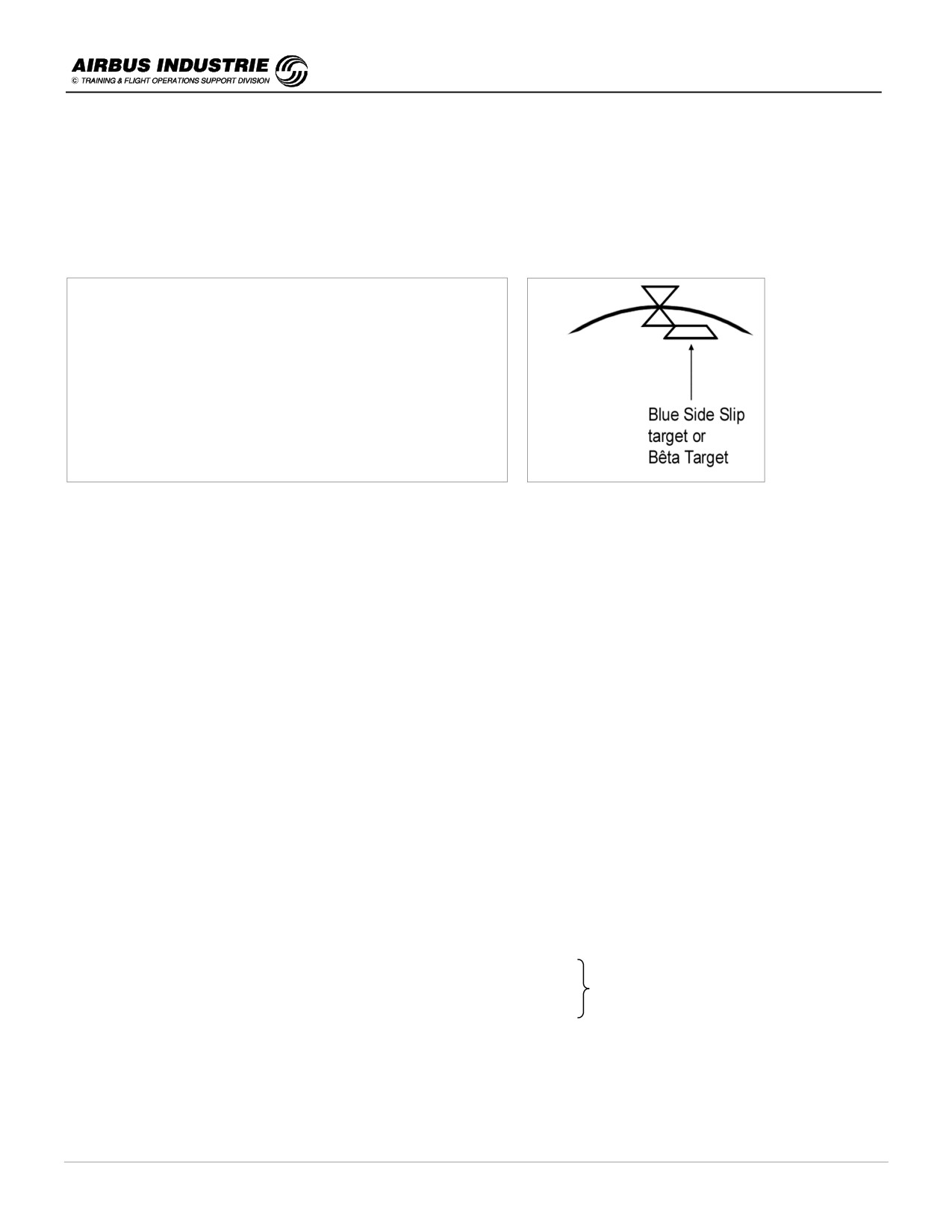
Hence in order to indicate the amount of rudder required to
fly properly with an EO at T/O, the measured SIDE SLIP
index is SHIFTED on the PFD by the residual side slip
computed value, and displayed in blue instead of yellow,
and called BETA TARGET; by pressing the rudder pedal to
center the BETA TARGET index, the pilot will fly with the
RESIDUAL SLIP as required by the EO condition. Thus the
A/C will fly at constant heading with roll surfaces retracted.
As a summary, in case of engine failure at T/O:
-
smoothly pitch the A/C down to keep safe speed (as per SRS),
-
no hurry to react on the pedals, since the A/C is laterally safe,
-
center the Beta target with rudder pedals and
-
zero the residual heading drift with small lateral stick inputs.
PROTECTIONS
One of the essential tasks of a pilot is to keep the A/C within the normal flight envelope, for safe and high performance
flight completion.
This task is not very easy on older generation aircraft when encountering dangerous or hazardous situations, such as
windshear.
The purpose of the protection provided is:
-
to give FULL AUTHORITY to the aircrew to CONSISTENTLY achieve the BEST POSSIBLE A/C performance in
those extreme conditions,
-
to reduce the risks of overcontrolling or overstressing the A/C and
-
to provide the pilot with AN INSTINCTIVE and IMMEDIATE PROCEDURE to achieve the best possible
performance when required.
The following protections are provided:
BANK ANGLE PROT
(max 67° - corresponding to a 2.5 g turn)
LOAD FACTOR PROT
(max 2.5 g in clean)
these 3 are
MAX PITCH PROT
(30° Nose Up - 15° Nose Dn)
linked
HIGH AOA PROT
(for BEST AERODYNAMIC PERFORMANCE)
HIGH SPEED PROT
(not to overshoot design speed limits)
These protections have NOT been designed to allow pilots to exceed the NORMAL FLT ENVELOPE, which is
considered as VIOLATION. These protections have been designed to assist pilots in emergency situations, where
under stress conditions only an instinctive and rapid reaction will save the situation. The protections make this reaction
possible. See chapter 22.
DATE: JAN 2001
Page 131
UDY0102
A320 INSTRUCTOR SUPPORT
NORMAL OPERATION
!
Alternate Law
In some cases of double failure, the integrity and redundancy of the computers and peripherals are not high enough to
achieve the Normal law with its protection.
The degration is progressive depending upon the availability of remaining peripherals or computers.
The ALTERNATE LAW characteristics (triggered usually in case of 2 failures) are:
-
Pitch Law = same as normal law with FLARE in DIRECT,
-
Lateral Law = Roll Direct,
-
most protections lost except:
➔ Load factor protection and
➔ Bank angle protection if roll normal still available.
What happens at the border of the flight envelope ?
It is as on a NON PROTECTED A/C:
-
in high speed, natural aircraft static stability is restored with OVER SPEED WARNING and
-
in low speed, the auto pitch trim stops at Vc prot (below VLS) and natural longitudinal static stability is restored,
with STALL WARNING at 1.03 VS1g.
NOTE:
In certain failure cases such as loss of VS1g computation or loss of 2ADRs, the longitudinal static stability cannot be
restored at low speed; in case of loss of 3ADRs it cannot be restored both at low and high speed.
The yaw is either yaw alternate associated to roll direct or mechanical yaw all through pedals and rudder trim.
As a summary with ALTN law:
-
within the Normal Flight Envelope, the handling characteristics are the same in pitch as with the normal law and
-
outside the Normal Flight Envelope, the pilot must take proper preventive actions to avoid loss of control, or high
speed excursions as he would do it on any non protected A/C.
Note that, in ALTN law VMO is reduced to 320 kt and that A.FLOOR is inhibited.
!
Direct law
In case of triple failure (e.g. IR or DOUBLE IR (2nd not self detected)), direct law is triggered:
-
elevator deflection is proportional to stick deflection; the maximum deflection is a function of CONF and CG,
-
aileron and spoiler deflections are proportional to stick deflection but vary with the A/C CONF and
-
pitch trim is commanded manually.
As a summary with DIRECT law:
The handling characteristics are those of a very good natural aircraft quasi independent of CONF and CG, and
thus obviously with no protections, no automatic pitch trim, but with overspeed or stall warnings.
NOTE:
Refer to FCOM 1.27.30 for complete information.
DATE: JAN 2001
Page 132
UDY0102
A320 INSTRUCTOR SUPPORT
NORMAL OPERATION
!
Indications
The degradation of control laws is indicated on ECAM as well as on PFD.
On ECAM:
in ALTN:
ECAM EW/D
FLT CTL ALTN LAW (PROT LOST)
MAX
SPEED 320
in DIRECT:
ECAM EW/D
FLT CTL DIRECT LAW (PROT LOST)
MAX
SPEED 320/.77
MAN PITCH TRIM USE
On PFD:
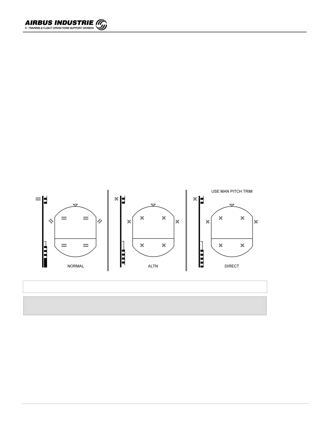
The flight control status awareness of the crew is enhanced on the PFD.
Indeed the availability of PROTECTIONS is outlined by specific symbols = (green), and by the specific formatting of the
low speed information on speed scale, in normal law.
When protections are lost, amber crosses X are displayed instead of the green protection symbols =.
When automatic pitch trim is no longer available, this is indicated as USE MAN PITCH TRIM amber message below
the FMA.
Fly By Wire status awareness through the PFD
Just by watching his main instrument the PFD,
the pilot is immediately aware of the control law status and ops consequences
DATE: JAN 2001
Page 133
UDY0102
A320 INSTRUCTOR SUPPORT
NORMAL OPERATION
!
Additional information regarding control laws
THE MECHANICAL BACK UP
The purpose of the mechanical back up is to be able to achieve all safety objectives in MMEL dispatch condition, thus
to cover a TEMPORARY TOTAL ELEC LOSS, or a TEMPORARY LOSS OF 5 FBW COMPUTERS, or to cover the
loss of BOTH ELEVATORS, or a total loss of AILERONS and SPOILERS.
In case of such MOST IMPROBABLE FAILURE, the mechanical B/UP allows the pilot to SAFELY STABILIZE THE
AIRCRAFT using the RUDDER and MAN PITCH TRIM while reconfiguring the systems.
Pitch control is through Pitch Trim Wheel. Act smoothly on it since the effect of the THS is very important due to its
large surface.
Lateral control is through RUDDER: the rudder induces a significant roll with a slight delay. So apply some rudder to
turn, and wait for the reaction; when you wish to stabilize wings level, anticipate.
The problem here is NOT TO FLY THE A/C ACCURATELY, but to KEEP THE A/C IN A SAFE STABILIZED
ATTITUDE, allowing the lost systems to be restored.
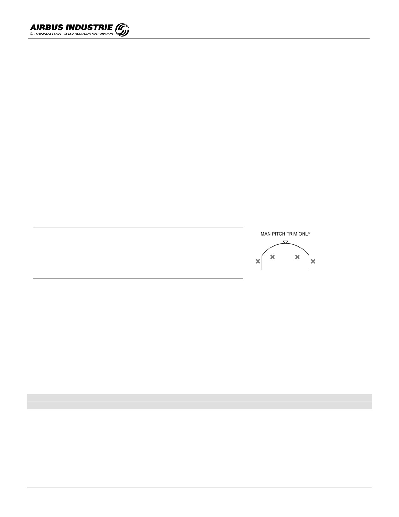
The pilot is immediately aware of the MECHANICAL B/UP by the red message on the PFD: MAN PITCH TRIM ONLY.
NOTE:
Mechanical B/UP is effectively most improbable with the FBW
architecture.
Let us keep in mind that in case of total ELEC failure, the ELAC 1
and SEC 1 are fed either by CSM-G or BAT and you will fly in ALTN
law!
ABNORMAL ATTITUDES
Suppose that for any reason the A/C is FAR OUTSIDE the NORMAL FLIGHT envelope and reaches some
ABNORMAL ATTITUDES, the normal controls are actually modified so as to allow the crew to best efficiently regain
normal attitudes (a typical reason would be a mid air collision …).
The so called ABNORMAL ATTITUDE law is:
-
pitch ALTN with load factor protection (without autotrim) and
-
lateral Direct Law with yaw alternate.
These abnormal laws are triggered when Pitch (50° up, 30° down), Bank (125°), AOA (30°, -10°), Speed (440, 60)
Mach (0,96; 0,1) are reaching extreme values.
As for aerodynamic upsets, it is MOST IMPROBABLE that they make the aircraft reach such attitudes, because the
FBW PROTECTION would have reacted FAR IN ADVANCE thus minimizing the effect of such upsets.
The FBW architecture and control laws explain why upset recovery maneuvers need not to be trained on Airbus
protected A/C.
DATE: JAN 2001
Page 134
UDY0102
A320 INSTRUCTOR SUPPORT
NORMAL OPERATION
!
Side Stick and Priority P/B
* When the pilot acts on the stick, he actually sends an order (an electrical signal) to the FBW computer. Thus
if the PNF acts on the stick as well, both signals or orders are added.
Thus, as on any other aircraft type, PF and PNF shall not act on the stick simultaneously.
If the PNF (or training captain) needs to take over, he must press on the priority P/B and announce
"I have controls".
In case of a pilot who collapses on the stick, or in case of a mechanical side stick failure leading to a jammed
stick (there is no ECAM caution associated), the "failed" stick order is added to the "non failed" side stick
order.
In such a case, the pilot will press the priority P/B during at least 30 sec. in order to deactivate the "failed"
side stick.
* In case of a SIDE STICK FAULT ECAM warning due to an electrical failure, the affected side stick order sent
to the computer is forced to zero; in other words the affected side stick is deactivated, which explains why
there is no associated procedure to that warning.
NOTE:
When a side stick is deactivated by the opposite side stick priority P/B, it can be reactivated by pressing its own
priority P/B.
DATE: JAN 2001
Page 135
UDY0102

A320 INSTRUCTOR SUPPORT
NORMAL OPERATION
25 - FLIGHT CONTROLS - HIGHLIGHTS ON THE PROTECTIONS
One of the essential tasks of the crew is to keep the A/C within the LIMITS of the NORMAL FLT ENVELOPE.
But circumstances bring pilots to violate those limits, because of EXTREME SITUATIONS, or mishandling or
mismanagement of the A/C.
Protections have been built so as:
-
to give FULL AUTHORITY to the crew to CONSISTENTLY achieve the BEST ACHIEVABLE A/C
PERFORMANCE in extreme conditions,
-
to REDUCE the RISKS of overcontrolling / overstressing the A/C and
-
to provide an INSTINCTIVE, IMMEDIATE procedure to the crew to achieve that BEST POSSIBLE
PERFORMANCE.
!
Bank angle protections
± 67° in Normal Flight envelope (2.5 g level flight).
± 45° in High Speed protection.
The Bank protections prevents ANY MAJOR UPSET or pilot mishandling to bring the A/C in high bank situations where
the recovery technique is complex due to the difficulty to properly assess the situation thus to readily react. It provides
full authority to the crew to achieve MOST EFFICIENTLY any required roll maneuver.
!
High speed protection
Beyond the design speeds VD/MD, which are greater that VMO/MMO, there are potentially aircraft control problems,
structural problems due to high air loads. Therefore the margin between VMO/MMO and VD/MD must be such that any
possible overshoot of the normal flight envelope does not cause any major problem.
In order to protect the A/C against dangerous phenomena which might be encountered in a dive or a vertical upset, the
high speed protection adds a positive NOSE UP G demand to the stick order. Incidently, this has allowed the margin
betwen VMO/MMO and VD/MD to be reduced.
Thus in a dive:
-
STICK FREE, the A/C will slightly overshoot VMO/MMO and fly back towards the envelope and
-
STICK FULL FORWARD, the A/C will significantly overshoot VMO/MMO without reaching VD/MD; at around
VMO + 16 / MMO + 0.04 the stick nose down authority is smoothly reduced to zero which does not mean that the
aircraft stabilizes at that speed.
Thus the pilot has full authority to achieve a high speed / steep dive escape maneuver when required with a REFLEX
action on the stick.
NOTE:
OVERSPEED warning is provided.
DATE: JAN 2001
Page 136
UDY0102
A320 INSTRUCTOR SUPPORT
NORMAL OPERATION
!
Load factor protection
On commercial aircraft high load factors are encountered in evasive maneuvers from potential collision, or CFIT etc.
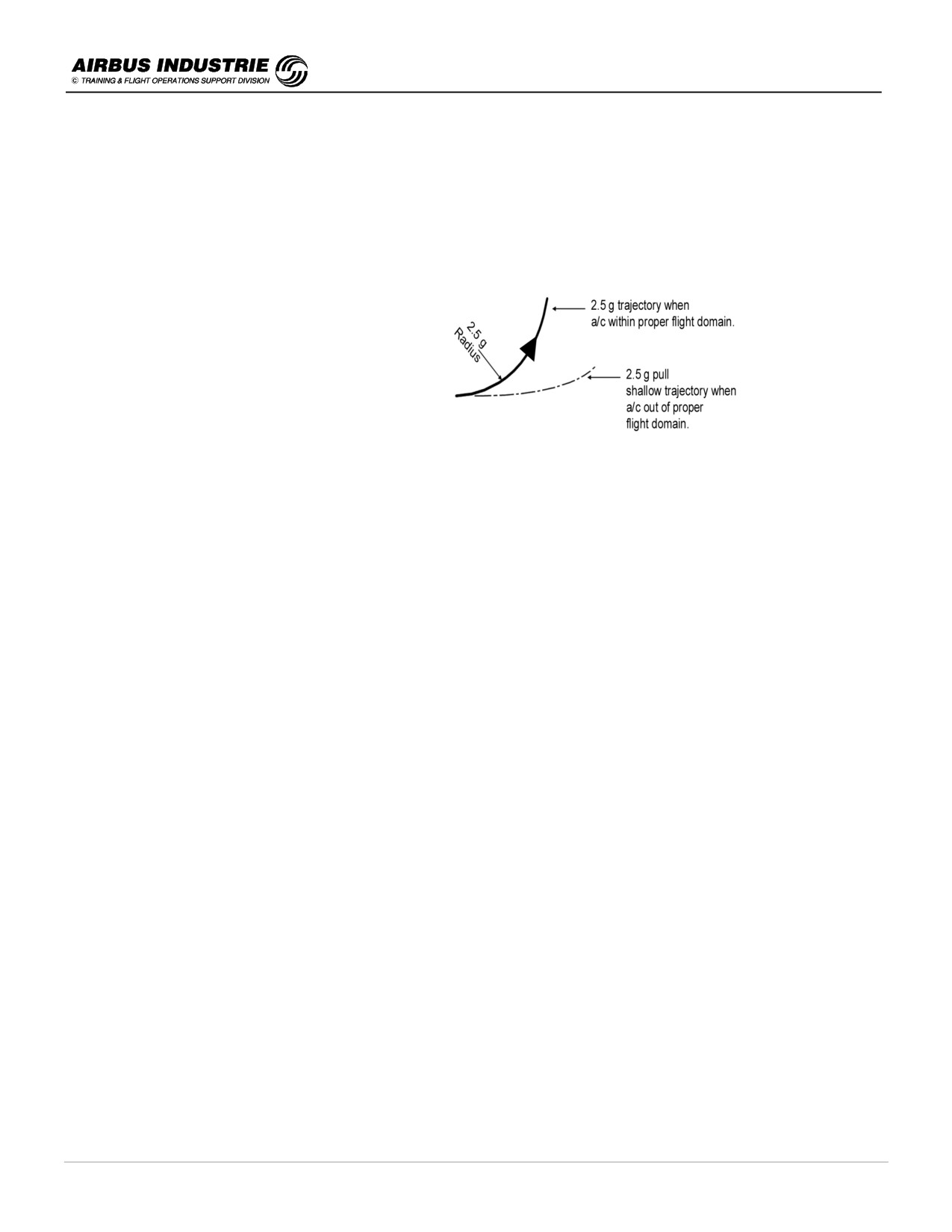
Pulling “g” is efficient as long as the resulting maneuver is actually flown with this g number; if the A/C is unable to fly
this trajectory or maneuver, pulling "g" is detrimental for the performance.
On commercial aircraft the maximum load allowed structurally is:
-
2.5 g in clean CONFIG
-
2.0 g with FLAPS extended
On most commercial A/C, the flight domain where an efficient 2.5 g maneuver is possible, is very remote.
Furthermore no G load continuous information is provided in cockpits, which leads to the fact that airline pilots are not
used to control this parameter .
This is, by the way, substantiated by the experience which shows, that in emergency situations, the reaction on a yoke
or stick is initially HESITANT; then LATER it is AGGRESSIVE.
With the LOAD FACTOR PROTECTION, the pilot may IMMEDIATELY and INSTINCTIVELY pull full AFT STICK:
-
the A/C will initially fly a 2.5 g maneuver without loss of time; then if the pilot still has to keep full aft stick because
not clear from danger, the HIGH AOA PROT will take over. The load factor protection enhances the high AOA
protection.
The G LOAD PROT allows an IMMEDIATE REACTION thus escape, without any risk of overstressing the A/C.
The experience also shows that an immediate 2.5 g reaction provides a LARGER OBSTACLE CLEARANCE than a
maneuver achieved HESITANTLY, with a high G load delayed reaction (2 sec delay).
!
High Pitch Attitude protection
Excessive pitch attitudes caused by upsets or undue maneuvres lead to hazardous situations:
-
too high Nose Up
➔ very rapid loss of energy and
-
too low Nose Dn
➔ very rapid gain of energy.
Furthermore no emergency situation requires to fly at attitudes greater than [+ 30°, - 15°].
DATE: JAN 2001
Page 137
UDY0102
A320 INSTRUCTOR SUPPORT
NORMAL OPERATION
Hence the pitch attitude protection will prevent any upset to pitch the A/C beyond those limits.
Furthermore the pitch attitude protection ENHANCES the high speed, high load factor and high AOA
protections.
!
High AOA protection
The high AOA protection gives full authority to the pilot to achieve consistently the best lift achievable by the aircraft, by
pulling full aft stick in dangerous situations which is instinctive, while minimizing the risks of stalls or loss of control.
The high AOA protection is an AERODYNAMIC protection:
-
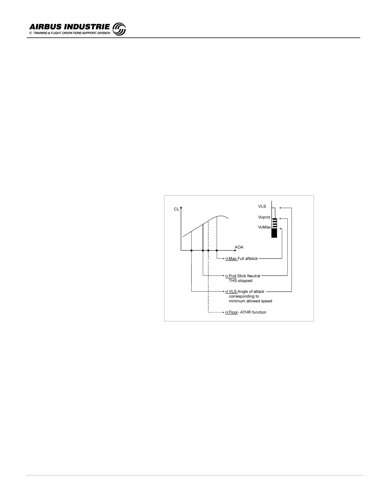
if the pilot exceeds the normal flight envelope for any reason, the pilot will be aware of that fact because the auto
pitch trim stops; the A/C will sink down to maintain its current angle of attack (α PROT, strong static stability),
which is a significant change in the A/C behaviour.
-
if he then pulls full aft stick, he commands MAX AOA which nearly corresponds to ALPHA CL Max; furthermore if
the speed brakes were extended, they automatically retract.
Additionally to this aerodynamic protection 3
ENERGY features enhance it:
- if ATHR is in speed mode, it will not allow
the speed to drop below VLS even if the
target speed is below VLS,
- a LOW ENERGY aural warning is triggered
when the a/c energy level drops below a
given threshold. Function of IAS,
ACCEL/DECEL, FPA etc.
e.g. if the a/c decelerates at 1 kt/s and the
FPA = - 3°, the warning will come up at
approx VLS - 8 kt. If the FPA = - 4°, the
warning will come up at approx VLS - 2 kt.
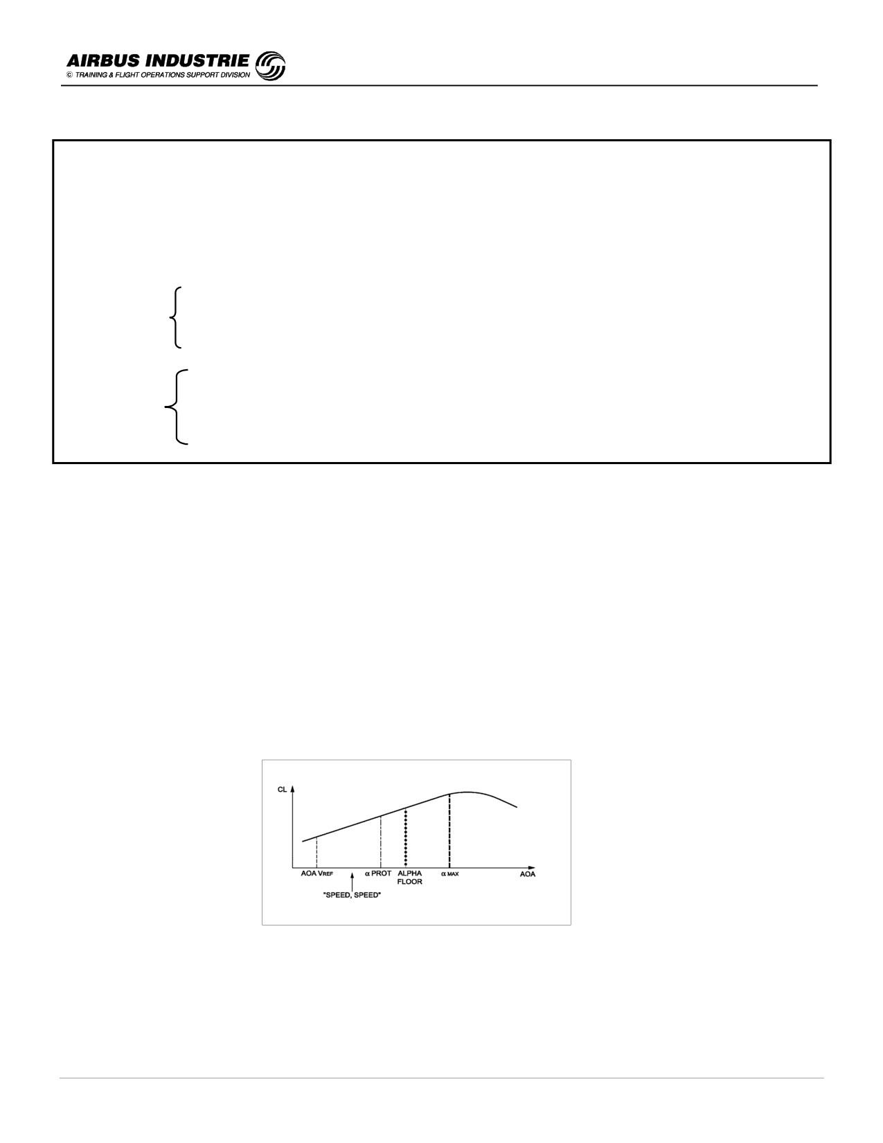
This warning SPEED - SPEED - SPEED drives the pilot towards the SPEED scale so as to re-adjust the thrust. It
comes up just before A.FLOOR engages. It is available below 2000 ft RA, if FLAP ≥ 2.
-
If the AOA still increases or the speed still drops, the angle of attack reaches ALPHA FLOOR threshold, where the
ATHR sends TOGA thrust and engages except if one Engine Out.
DATE: JAN 2001
Page 138
UDY0102
A320 INSTRUCTOR SUPPORT
NORMAL OPERATION
In case of an emergency situation such as Windshear or CFIT, where the pilot wishes to get the BEST
PERFORMANCE of the A/C, he is fully assisted to achieve this goal by:
-
the ATHR which adds thrust to maintain the Speed above VLS,
-
the Low Energy Speed - Speed warning which enhances pilot awareness,
-
the ALPHA FLOOR which provides TOGA thrust,
-
the HIGH AOA protection which provides maximum aerodynamic lift and
-
the automatic Speed Brake retraction which minimizes the drag.
Procedures in case of GPWS / SHEAR
Thrust Levers TOGA
Pull Full Aft stick *
Maintain wings level initially
(*) for shear fly SRS, till full aft stick.
This gives you MAX LIFT / MAX THRUST / MINI DRAG, immediately.
Consequently the resulting CFIT escape maneuvers are BY FAR more efficient.
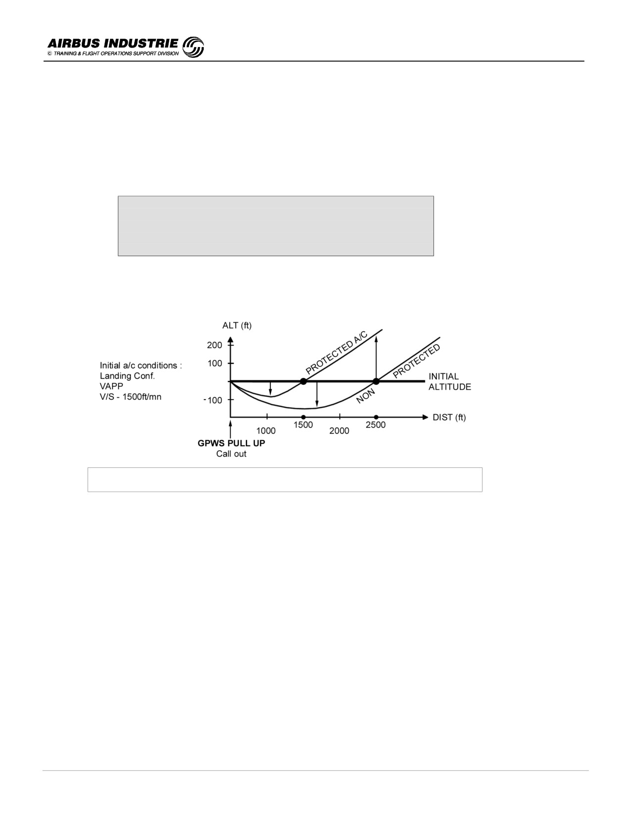
CFIT escape maneuvers on Protected and Non Protected A/C
These are typical trajectories flown either by all PROTECTED A/C (A320, 330 or 340), or by all NON PROTECTED
A/C
(A310, B737, B747, B777 !), when the pilot applied the escape procedure after hearing the GPWS PULL UP
Warning.
This demonstrates the efficiency of the protection which ensures a 50% lower duck under, a 50% shorter bucket
distance, a more than doubled safety margin in terms of reaction time and a significant altitude gain (≅ 250ft).
These characteristics are common to all protected A/C. This is because the escape procedure is simple to achieve,
and allows the pilot to fly the A/C at a constant AOA close to the max AOA, whereas it is most difficult to fly the stick
shaker AOA on a non protected aircraft.
DATE: JAN 2001
Page 139
UDY0102
A320 INSTRUCTOR SUPPORT
NORMAL OPERATION
26 - PREDICTIVE AND REACTIVE WINDSHEAR
!
General
During take off and landings, windshear and microbursts have been the cause of numerous aircraft accidents.
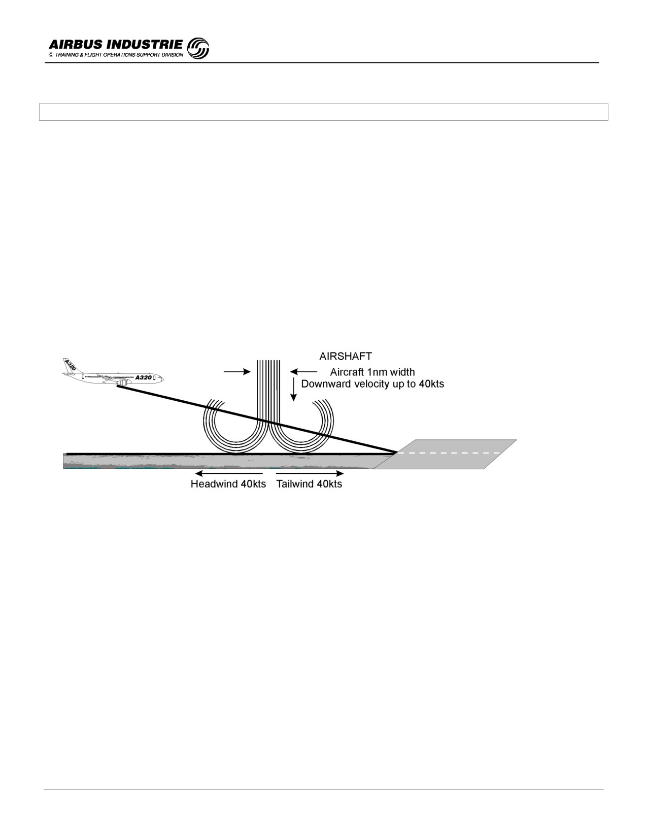
This type of phenomena is mostly due to cool shaft of air, like a cylinder, between ½ NM to 1,5 NM width that is moving
downward. When the air encounters the ground, it mushrooms in a horizontal direction curling inward at its edges.
The downward airmass velocity in such narrow shafts ranges from 20 kts to 40 kts; when it reaches the ground, the
outflow resulting winds vary from front to back with velocities ranging from 20 kts to 80 kts.
The microbursts affect the aircraft safety for 2 reasons:
1. The aircraft flies in the airmass. When the airmass moves downward so does the aircraft. The aircraft flight path is
thus severely affected.
2. The aircraft lift is related to the relative velocity of the air traveling over the wing. When the wind varies suddenly
from front to back, the lift significantly reduces which causes the aircraft to descend, or to reach very high AOA.
The windshear and microbursts are thus a hazardeous phenomenon for an aircraft at take off and landing. Thus the
strategy adopted to prevent catastrophic consequences is:
1. Increase crew awareness of potential microburst or windshear so as to delay take off or landing.
⇒ PREDICTIVE WINDSHEAR SYSTEM.
2. Inform the crew of unexpected airmass variations.
⇒ FPV sudden drop, Approach Target Speed variations (GS mini).
3. Warn the crew of significant loss of energy.
⇒ Low energy warning (SPEED, SPEED, SPEED), REACTIVE WINDSHEAR SYSTEM.
4. Provide efficient tools to escape out of the shear or get through.
⇒ ALPHA FLOOR (TOGA from ATHR), SRS pitch order (AP, FD) high AOA protection, GS mini.
DATE: JAN 2001
Page 140
UDY0102
A320 INSTRUCTOR SUPPORT
NORMAL OPERATION
!
Increase crew awareness of POTENTIAL microburst or windshear
The best strategy is to AVOID microbursts, thus delay T/O or APPR. In order to do so, the pilot needs to be advised
that such phenomena will be encountered.
PREDICTIVE WINDSHEAR (PWS)
When the airshaft of a microburst reaches the ground, it mushrooms outward carrying with it a large number of falling
raindrops. The RADAR is able to measure the velocity of the water droplets, thus to assess wind variations.
As it scans across the windshear, it will detect raindrops moving toward it at one range, and raindrops moving away
from it at a greater range. The principle of the measure is the detection of the doppler frequency shift on the reflected
microwave pulses caused by the shear.
The radar can thus determine THE WIDTH of the SHAFT and THE SEVERITY of THE SHEAR by the droplet velocity
variations. When the SEVERITY exceeds a given threshold, windshear alerts are triggered.
The PWS operates AUTOMATICALLY when the A/C is below 2300 ft AGL, whether the radar is set On or Off.
An alert is issued (ICON and/or AURAL) if a SHEAR is DETECTED within 5 NM, at an altitude AT or BELOW 1500 ft
AGL.
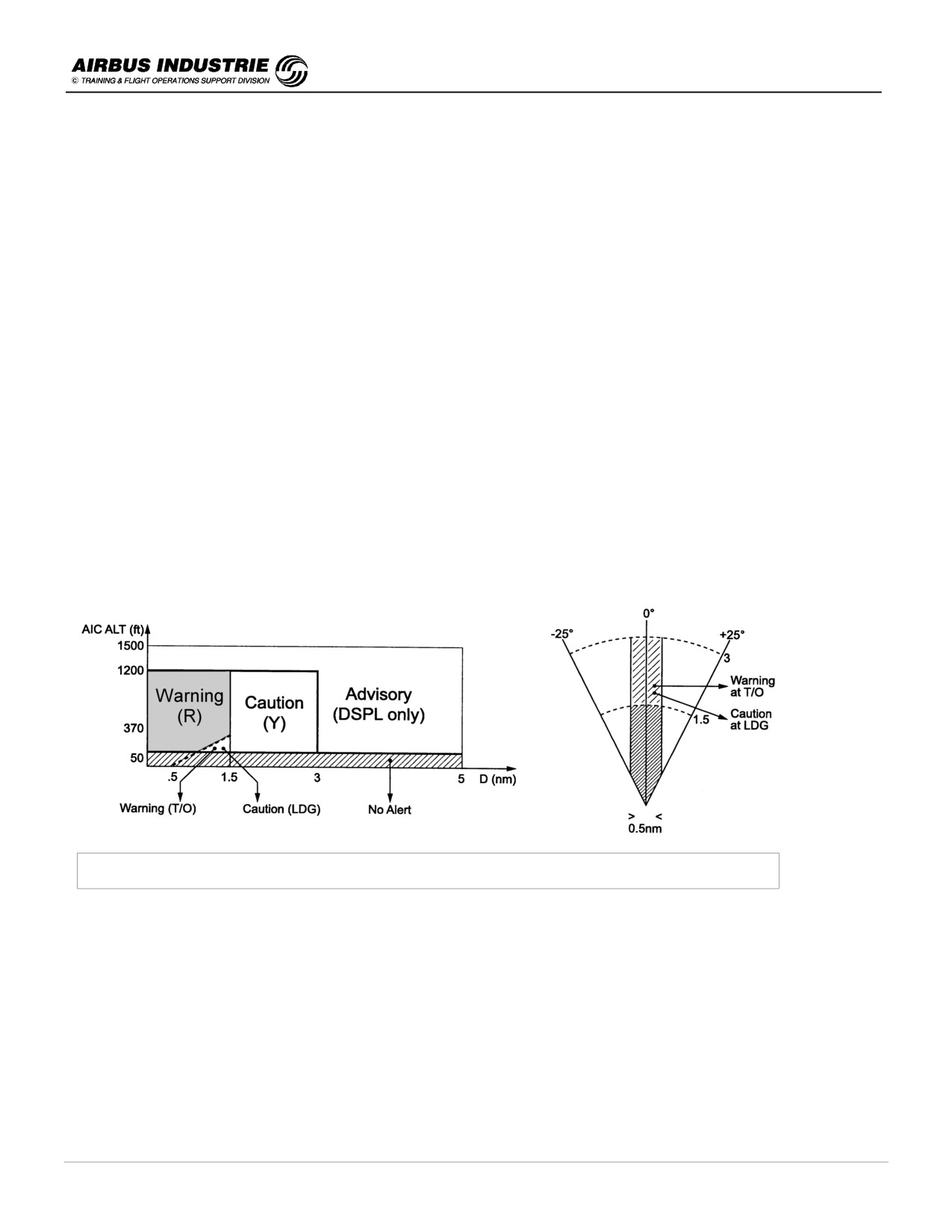
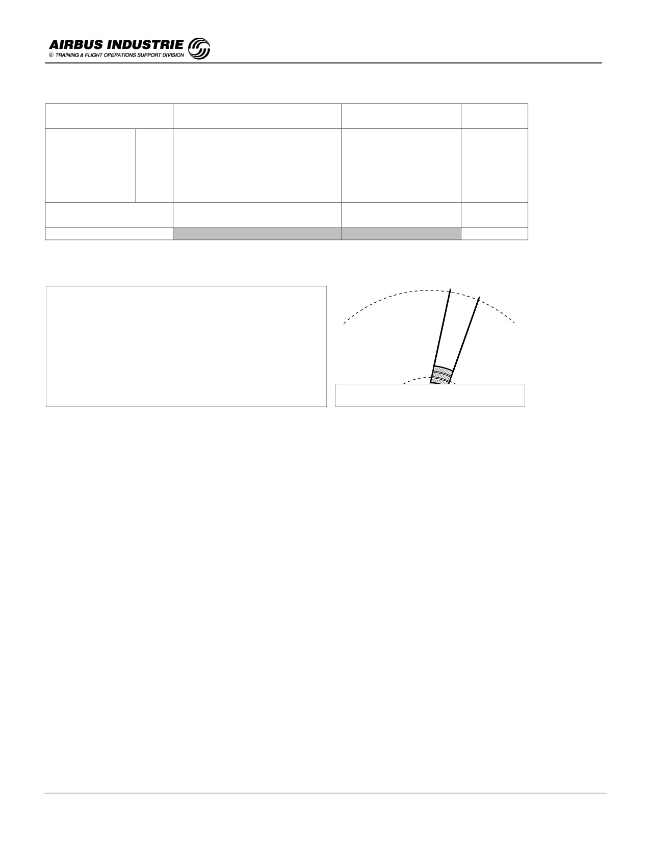
There are 3 types of alert levels: ADVISORY, CAUTION and WARNING function of the A/C altitude, flight phase (T/O
or Landing) and proximity of the microburst.
Windshear caution - Warning Areas at Take off and Landing
WINDSHEAR CAUTION and WARNING AREAS at T/O and Landing (warning is inhibited at IAS < 100 kt till 50 ft on
Lift off.
DATE: JAN 2001
Page 141
UDY0102
A320 INSTRUCTOR SUPPORT
NORMAL OPERATION
VISUAL
ALERT LEVEL
AURAL MESSAGE
VISUAL PFD
ND
WARNING
T/O
"WINDSHEAR AHEAD" (twice)
-------
------------------------------------------
WINDSHEAR AHEAD
Windshear
LDG
"GO AROUND WINDSHEAR
(red)
ICON
AHEAD"
WINDSHEAR AHEAD
CAUTION
"MONITOR RADAR DISPLAY"
ICON
(amber)
ADVISORY
ICON
The aural messages have priority over TCAS and GPWS, but are overridden by Reactive W/S and stall warning.
- Windshear ICON = Red + Black sectors and 2
Yellow radial lines.
-
Here a W/S is detected 2 NM ahead with a right
hand bearing.
Icon as depicted on ND
NOTE:
If the ND range is > 10 NM, a message W/S SET RNGE 10 NM (windshear, set range 10 NM) is provided.
NOTE:
A PWS OFF/AUTO switch is provided on the radar CTL panel. If set to OFF, PRED W/S OFF appears green or amber
on ECAM MEMO, once engines are running.
!
Procedure linked to PWS
-
Predictive windshear alert = highly probable windshear
-
At take off
➔ Delay Take Off or Reject during T/O Run
➔ If during Take Off roll or initial climb
-
TOGA
-
Monitor closely SPEED/SPEED TREND
-
Ensure that Flight Path clears any shear suspected area
-
If within the shear do NOT modify A/C configuration
-
At landing
➔ In case of ADVISORY ICON or CAUTION
-
Delay landing or Divert
-
Watch Radar and evaluate severity
DATE: JAN 2001
Page 142
UDY0102
A320 INSTRUCTOR SUPPORT
NORMAL OPERATION
-
Envisage CONF3
-
Use Managed speed and consider a VAPP increase
-
Use autopilot with ILS to help for an earlier detection of vertical path deviation
-
Be prepared for RECOVERY
➔ In case of GO AROUND WINDSHEAR AHEAD message
-
TOGA
-
Keep Configuration till out of shear
-
Follow SRS till full aft stick if necessary
!
Inform the crew of unexpected airmass variations
There are several cues provided on the EFIS, which assist the pilot in determining significant airmass variations
symptomatic of potential presence of microburst. These are available essentially in approach.
The cues are:
-
IAS trend arrow
-
IAS target during approach (GS mini)
-
FPV
-
Wind information on ND
During an approach the PF monitors essentially the PFD:
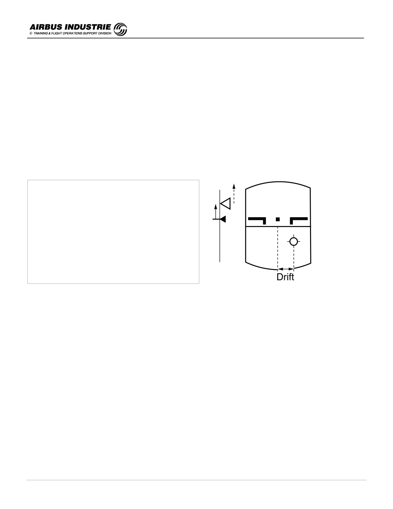
➔ The target speed during approach (GS mini), along with IAS trend arrow advises him immediately of a strong
headwind gust, or of a tailwing gust. If the ATHR is on, the resulting thrust management is therefore significantly
improved (here on the fig. - Head wind gust).
➔ The FPV position relative to the center of the PFD advises him of the wind direction.
If the PF flies a constant track and notices that the relative position of the FPV versus the center of the PFD varies
rapidly, he is going to deduce that the A/C experiences a wind direction change (here on the fig. - Wind from the
left leading to a drift to the right).
➔ A sudden FPV downward movement is the first cue, which allows the pilot to suspect that the A/C is going through
a downdraft.
PROCEDURE
➔ MONITOR THE ENERGY CUES, SPEED TREND, SPEED TARGET MOVEMENT in approach and FPV in
SUSPECTED SHEAR CONDITIONS.
➔ IN CASE OF SIGNIFICANT ENERGY LOSS
(FPV sinks down, Large SPEED TREND
down arrow …), GET PREPARED FOR RECOVERY.
DATE: JAN 2001
Page 143
UDY0102

A320 INSTRUCTOR SUPPORT
NORMAL OPERATION
!
Warn the crew of significant loss of energy
Two features are provided to the crew to achieve that goal:
1. the LOW ENERGY warning provided below 2000 ft R/A in CONF ≥ 2 and
2. the REACTIVE WINDSHEAR warning provided at take off and landing up to 1300 ft R/A in CONF ≥ 1.
NOTE:
At landing, the reactive windshear is inhibited below 50 ft.
The LOW ENERGY WARNING advises the pilot of a lack of energy (speed, thrust) which limits the maneuverability
capability of the A/C; if not taken care of rapidly, ALPHA FLOOR will then take over. Low energy warning is processed
by FCPC.
The energy level of the aircraft is translated into a value of Angle of Attack function of the A/C SPEED,
ACCELERATION, FLIGHT PATH ANGLE. This Angle of Attack value is compared to a threshold; when it overshoots
this threshold "SPEED, SPEED, SPEED" repetitive message is triggered. This warning drives the PF eyes to the
Speed Scale asking for rapid reaction.
Here are some typical values of the speed at which the warning could occur in two different circumstances:
DECEL
FPA
Warning at
- 1 kt/s
- 3°
VLS - 7 kt
- 1 kt/s
- 4°
VLS - 1 kt
Warning comes below VLS depending upon Low energy level.
In shear conditions this is the first warning to come up PRIOR TO ALPHA FLOOR.
The REACTIVE WINDSHEAR WARNING is provided by the Flight Envelope computer, which computes actual and
predicted energy level of the aircraft as an Equivalent Angle of Attack.
This Equivalent Angle of Attack is a function of detected HEAD/TAILWIND CHANGE conditions, MEAN WIND
COMPONENT, DETECTED DOWN DRAFT WIND, filtered by R/A value.
This Equivalent Angle of Attack is compared to a threshold function of the A/C configuration.
When the threshold is reached a "WINDSHEAR WINDSHEAR WINDSHEAR" aural warning is triggered, with an
associated WINDSHEAR red message on PFD.
The crew reaction to such a warning has to be immediate.
DATE: JAN 2001
Page 144
UDY0102
A320 INSTRUCTOR SUPPORT
NORMAL OPERATION
PROCEDURE
IF "SPEED - SPEED - SPEED" WARNING COMES UP
➔ WATCH SPEED SCALE and
➔ ADD THRUST.
IF REACTIVE WIND SHEAR WARNING COMES UP
•
BEFORE V1 - STOP (if significant SPD/SPD trend variations).
TAKE OFF
•
AFTER V1
- TOGA / FOLLOW SRS till full aft stick and KEEP CONF
IN FLIGHT
•
TOGA / FOLLOW SRS till full aft stick and KEEP A/C CONF
or in
- monitor FLIGHT PATH and SPEED,
APPROACH
- if AP ON, it automatically disengages at AOA PROT + 1°,
- if no FD, pitch to 17.5° initially and adjust for MINIMUM HEIGHT LOSS.
!
Efficient tools to escape
To assist the crew to escape, there are:
1. the ALPHA FLOOR which is function of the ATHR,
2. the SRS AP/FD pitch law and
3. the Fly By Wire High Angle of Attack protection.
ALPHA FLOOR condition is processed by FCPC and triggered by FMGC which engages ATHR and sends TOGA on
all engines.
ALPHA FLOOR provides an ADDITIONAL LEVEL of ENERGY when the A/C AOA gets very high.
ALPHA FLOOR is fully automatic and available from LIFT OFF to 100 ft R/A at Landing.
It is INHIBITED in case of ENG FAILURE.
ALPHA FLOOR is indicated on FMA as A.FLOOR which changes into TOGA LK when the A/C angle of attack has
decreased. The only means to get rid of TOGA LK (which means that TOGA thrust is locked) is to set ATHR OFF. (see
chapt. 18).
SRS AP/FD pitch law
The SRS pitch mode is used in T/O and GO AROUND so as to ensure the BEST A/C CLIMB PERFORMANCE, with
ALL ENG OPERATIVE and ENG FAILURE.
However it also ensures a MINIMUM CLIMB OUT FLIGHT PATH ANGLE, in order to cope with DOWNDRAFT or
WINDSHEAR situations.
This explains why the PROCEDURE asks the PF to FOLLOW THE FD PITCH BAR (or set AP ON) and POSSIBLY TO
PULL FULL AFT STICK so as to obey the SRS orders and thus minimize height losses.
DATE: JAN 2001
Page 145
UDY0102
A320 INSTRUCTOR SUPPORT
NORMAL OPERATION
The HIGH ANGLE of ATTACK protection
The HIGH ANGLE of ATTACK protection allows the PF to pull FULL AFT STICK if needed, either to follow the SRS FD
BARS or to rapidly counteract a down movement of the FPV / a height loss / a deviation below the final path or G/S, or
a GPWS warning.
Pulling full aft stick provides:
-
MAXIMUM LIFT
-
MINIMUM DRAG by automatic retraction of the speed brakes, should
those be extended.
For details see chap. 22.
DATE: JAN 2001
Page 146
UDY0102
A320 INSTRUCTOR SUPPORT
NORMAL OPERATION
27 - EGPWS AND GPWS
!
Technical Background
The Enhanced GPWS incorporates the functions of the basic GPWS with the following added features:
➔ Terrain Clearance Floor (TCF),
➔ Terrain Look Ahead Alerting and
➔ Terrain Awareness Display (TAD).
The purpose of the Enhanced GPWS functions is to provide a better situational awareness to the crew through the
TAD, and to give earlier CAUTION and WARNING to the pilot to initiate a safe recovery maneuver.
The computer incorporates a world wide TERRAIN DATA BASE with varying degrees of resolution. It has also an
airport data base (coordinates of runway center point of all hard surface runway longer than 3500 ft). The earth is
divided into grid sets with the record of the highest terrain altitude in each element of the grid. The resolution of the
data base is a function of the geographic location. It is a HIGH RESOLUTION GRID around an airport, and SMALL
RESOLUTION GRID away from airport. There are 5 levels of resolution (from 15 arc sec. to 5 mn arc or 5 NM).
Having an FMS (and possibly a GPS) on board, the EGPWS determines present position, track and ground speed,
which will be used to advise the crew of any potential conflict with terrain. When the terrain violates specific computed
boundaries on the projected flight path of the A/C, the associated threats will be announced to the crew.
a.)
Terrain Clearance Floor (TCF)
The TCF alert function adds an additional element of protection to the standard GPWS by alerting the pilot of
possible premature descent, (for example for NPAs), regardless of aircraft configuration.
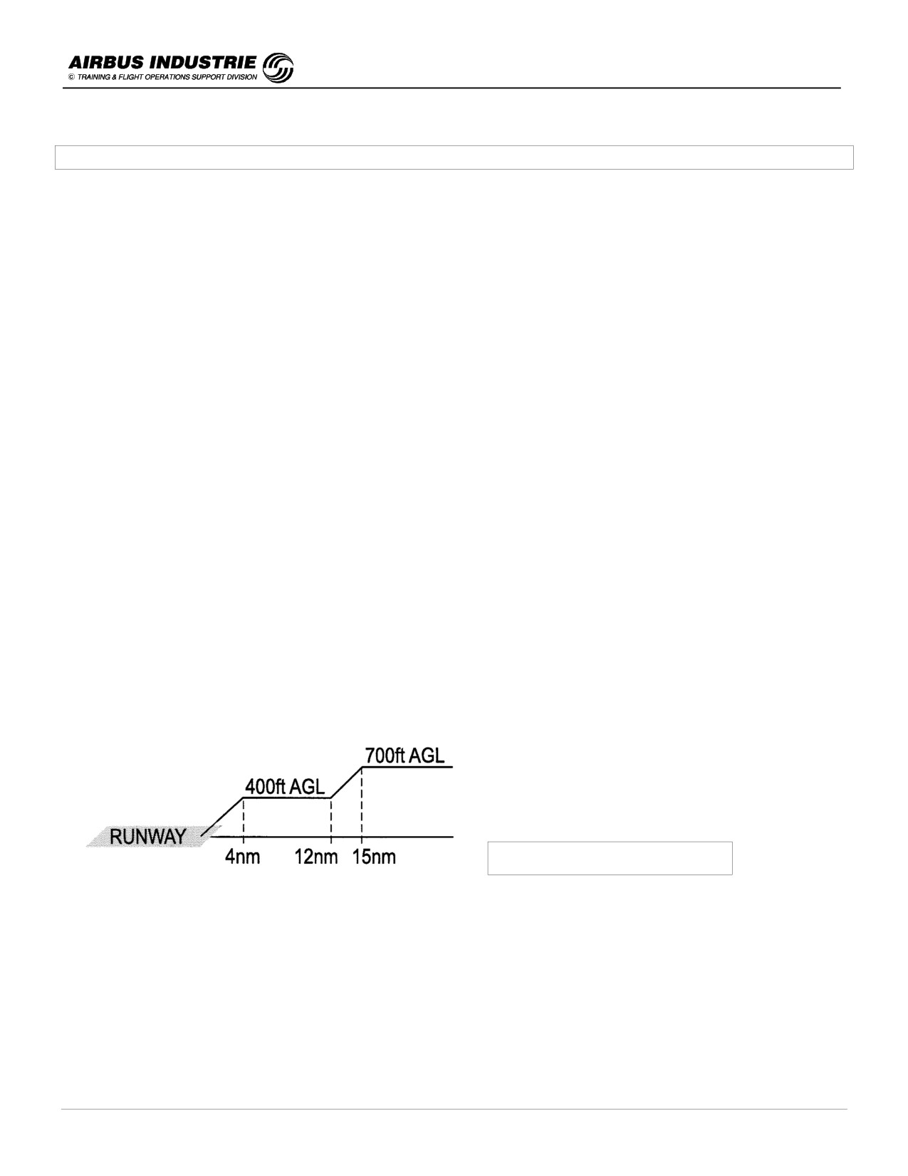
It creates an increasing terrain clearance altitude envelope around an airport, directly related to the distance
from the runway. When the aircraft enters this envelope, an alert is triggered.
The alert is a function of A/C position, of the nearest airport location and of current Radio Altitude measure
(R/A). It protects the A/C against an attempt to land on "no airfield".
The TCF is available in ALL FLIGHT PHASES and is a complement to the basic GPWS mode 4.
➔ AURAL MSG - TOO LOW TERRAIN (2)
➔ GPWS red light illuminates (see note in § b).
TCF Alert Envelope
NOTE:
As a reminder, the GPWS mode 4 TOO LOW TERRAIN alert is inhibited with the landing gear down.
DATE: JAN 2001
Page 147
UDY0102
A320 INSTRUCTOR SUPPORT
NORMAL OPERATION
b.)
Terrain Look Ahead Alerting
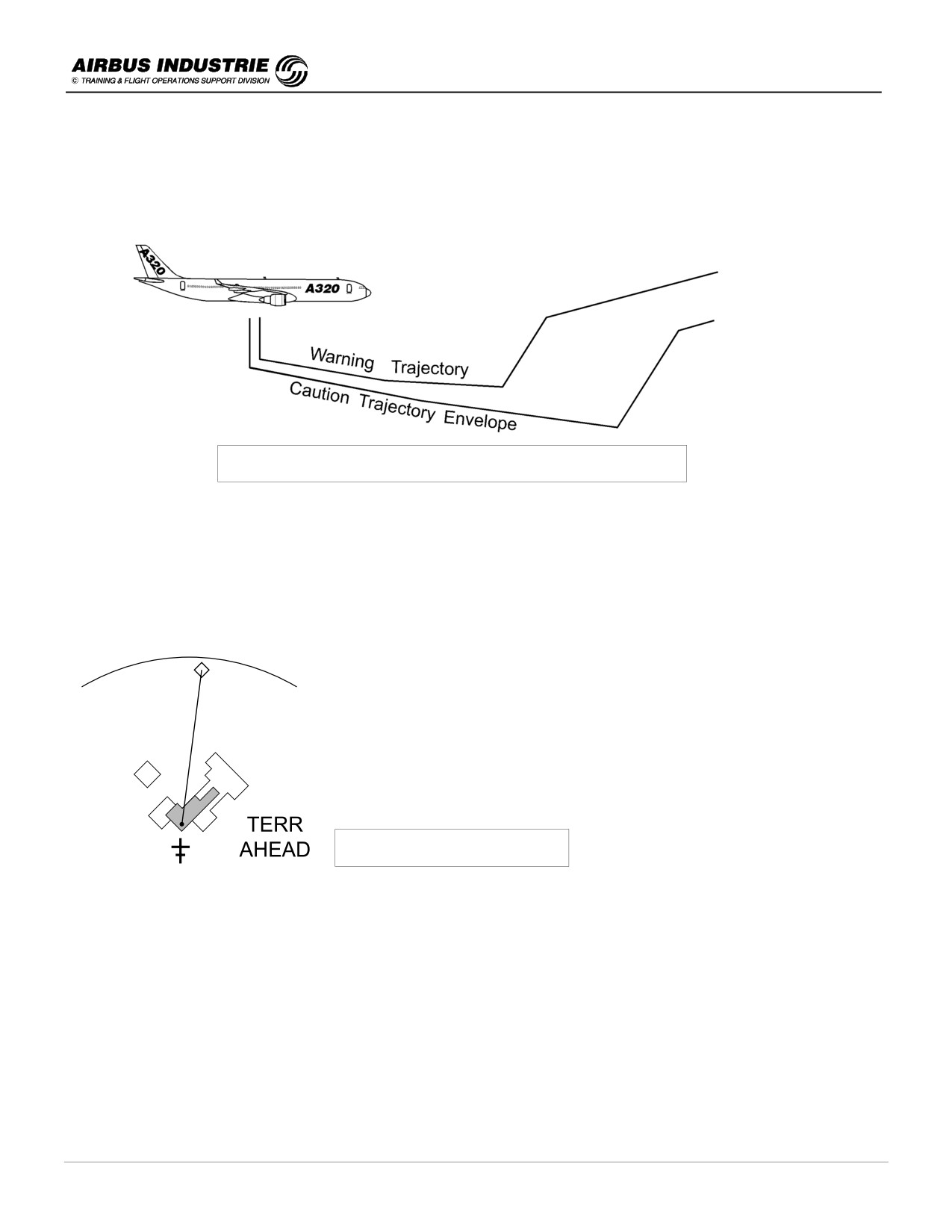
The Terrain Alerting algorithms compute two trajectory envelopes from the A/C position, speed and track, which
originate below the A/C as an added margin for safety. When the boundaries of these two envelopes conflict with the
terrain data, alerts are triggered.
Terrain Look Ahead Alerting envelopes
When the CAUTION ENVELOPE conflicts with the terrain:
➔ GPWS RED LIGHT (see NOTE below),
➔ TERRAIN AHEAD (amber) on ND,
➔ TERRAIN data displayed on ND with SOLID YELLOW areas and
➔ Aural "TERRAIN AHEAD" repeated every 7 sec.
This caution gives typically 60 sec reaction time prior to potential terrain conflict.
Typical Terrain Display on ND
When the WARNING ENVELOPE conflicts with the terrain:
➔ GPWS RED LIGHT (see NOTE below),
➔ TERRAIN AHEAD (RED) on ND,
➔ TERRAIN data displayed on ND with SOLID RED areas
➔ Aural "TERRAIN AHEAD, PULL UP" repeated continuously.
This warning gives typically 30 sec reaction time.
NOTE:
-
The EGPWS has priority over the PWS.
-
In case an airport is not stored in the EGPWS data base, the EGPWS uses the smallest resolution; this may cause
early and unexpected TERRAIN AHEAD / TERRAIN AHEAD / PULL UP alerts with terrain display popping up on
the ND. This must be reported to the Airline Operations.
DATE: JAN 2001
Page 148
UDY0102
A320 INSTRUCTOR SUPPORT
NORMAL OPERATION
Furthermore, when operating from/to airports known as not being in the data base, set EGPWS TERR P/B OFF on
the overhead panel when the A/C is within 15 NM from that airport.
-
If TERR ON ND P/B is pressed OFF, and a caution or warning is triggered, terrain data are automatically displayed
on the ND, and the TERR ON ND light comes up.
-
On latest EGPWS version, the GPWS / G/S lights located on the left and right main instrument panels next to the
PFD are replaced by PULL UP / GPWS light. PULL UP red light comes up when TCF or TAD alerts are triggered.
c.)
Terrain Awareness Display (TAD)
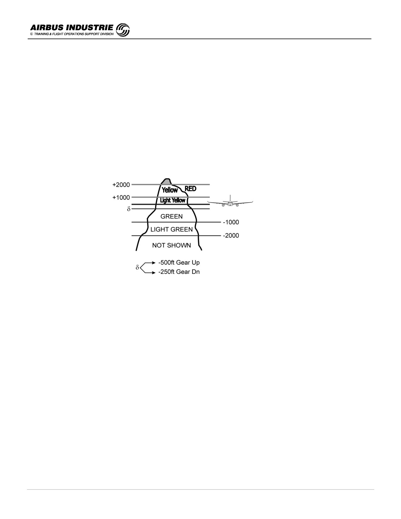
The TAD displays an image of the surrounding terrain in varying density dot patterns of Green, Yellow and
Red.
The display is generated by comparing the A/C altitude to terrain data in the EGPWS data base; thus those
patterns represent a SPECIFIC TERRAIN SEPARATION with respect to the aircraft.
The terrain is not shown if more than 2000 ft. below the A/C altitude or if its elevation is within 400 feet of the
runway elevation nearest the A/C.
d.)
Recall of the basic GPWS mode 1 to 5 functions.
Mode 1: Excessive Descent Rate
WARNS THAT THE A/C DESCENT RATE WITH RESPECT TO ALTITUDE AGL IS EXCESSIVE.
AVAILABLE in ALL FLIGHT PHASES.
Alert:
1) - SINK RATE (twice)
2) - then PULL UP (continuously)
3) - GPWS RED LIGHT
Mode 2: Excessive closure to Terrain
WARNS THE PILOT OF RAPIDLY RISING TERRAIN WITH RESPECT TO THE A/C.
Alert:
1) - TERRAIN - TERRAIN
2) - then PULL UP (continuously)
3) - GPWS RED LIGHT
Mode 2A active during climb out, cruise, initial approach when Flaps are not in landing conf and A/C not on G/S
center line.
Mode 2B is desensitized to permit landing maneuvers close to terrain WITHOUT UNDUE alerts. It is
automatically triggered when Flaps in Ldg Conf or ILS G/S within 2 dots.
With LDG GEAR dn and flaps ldg conf, PULL UP call is suppressed.
Mode 3: Altitude Loss After T/O
WARNS THE PILOT OF A SIGNIFICANT ALTITUDE LOSS AFTER T/O OR LOW ALTITUDE GO AROUND (>
245 ft) with gear or flaps not in landing conf.
Alert:
1) - DON'T SINK
2) - GPWS RED LIGHT
DATE: JAN 2001
Page 149
UDY0102
A320 INSTRUCTOR SUPPORT
NORMAL OPERATION
Mode 4: Unsafe Terrain Clearance
WARNS THE PILOT FOR INSUFFICIENT TERRAIN CLEARANCE AS A FUNCTION OF THE PHASE OF
FLIGHT, SPEED AND/OR A/C CONFIGURATION.
Alert:
TOO LOW TERRAIN
TOO LOW GEAR
(500 ft R/A)
TOO LOW FLAPS
(245 ft R/A)
GPWS RED LIGHT
Actually this mode is divided into three submodes:
• 4A
Cruise approach with Gear Up. This provides alerting cruise for flight into Terrain where terrain is not
rising significantly or A/C not descending rapidly:
TOO LOW TERRAIN - TOO LOW GEAR (if R/A < 500, IAS < 190).
• 4B
Cruise approach with Gear Down and Flaps not in landing Conf:
TOO LOW TERRAIN - TOO LOW FLAPS (if R/A < 245, IAS < 160)
• 4C
After T/O or low altitude Go Around when Gear or Flaps are not in landing conf. It alerts the crew that
the terrain is rising MORE STEEPLY than the A/C is climbing. A MINIMUM TERRAIN CLEARANCE
(MTC) is defined and increases with R/A up to 500 ft if IAS ≤ 190 kts and up to 1000 ft if IAS increases
to 250 kts: TOO LOW TERRAIN.
Mode 5: Excessive G/S deviation
WARNS THE PILOT WHENEVER THE A/C DESCENDS BELOW THE GLIDE SLOPE.
Alert:
GLIDE SLOPE / GLIDE SLOPE with G/S amber light
It starts below 1000 ft AGL, and the loudness and rate of the message increases. Below 150 ft AGL it is
desensitized to reduce nuisance alerts. Pressing the G/S P/B stops the alert and turns off the amber G/S; in case
of a new violation the alert comes back again.
!
Commands and Controls Specifics
EGPWS functions (TFC - TAD - Terrain Look Ahead Alerting).
-
Commanded ON on the overhead panel by TERR P/B is set next to the other GPWS P/Bs.
The last 2 EGPWS functions provide displays on ND which are incompatible with the Radar display. Therefore on
the main instrument panel, there is a specific P/B whether to display the terrain or not.
-
TERR on ND P/B next to each ND
When ON, the radar image is suppressed; TILT indication goes OFF and TERR comes up instead on ND. The
image of the terrain has a "texture" different from the radar image, and the sweeping starts from the middle of the
screen ("curtain sweep").
When OFF, the terrain data is not displayed on ND unless an alert comes up where the terrain "pops up" (and
supersedes PWS message).
GPWS basic functions - particulars
For GPWS, the landing configuration is by DEFAULT FLAPS FULL. If landing is to be peformed in FLAPS 3 (for go
around climb performance reasons or in case of windshear). LDG FLAP 3 p/b should be selected ON on OVHD panel.
Flap mode is then inhibited when CONFIG 3 is selected.
In this case ECAM LDG MEMO displays FLAPS ……… 3 rather than FLAP ……… FULL.
Note that on MCDU PERF APP page, LDG CONF selection does compute VLS and associated deceleration prediction
but is not connected to GPWS.
NOTE:
The GPWS red light on the main instrument panel indicates an alert triggered by any mode of the GPWS or EGPWS
(TAD and TCF).
On latest GPWS / EGPWS versions, the GPWS / G/S lights located on the left and right main instrument panels next to
the PFD are replaced by PULL UP / GPWS lights. The PULL UP red light comes up when GPWS MODE 1 and 2 alerts
are triggered, as well as when EGPWS TAD or TCF alerts are triggered. The GPWS amber light comes up when the
other GPWS mode alerts are triggered.
DATE: JAN 2001
Page 150
UDY0102

A320 INSTRUCTOR SUPPORT
NORMAL OPERATION
!
Procedures
a.)
Precautions:
-
EGPWS specific functions: TAD, TERRAIN LOOK AHEAD ALERTING and TFC may be used ONLY IF NAV
ACCY IS CHECKED GOOD.
Hence if NAV ACCY CHECK IS NEGATIVE (or GPS NOT PRIMARY AND NAV ACCY CHECK IS
NEGATIVE), set EGPWS OFF.
-
TAD function is to be used for TERRAIN AWARENESS, BUT NOT FOR NAVIGATION.
NOTE:
On early EGPWS versions, EGPWS must be inhibited if A/C is pin programmed with QFE, until the EGPWS is
modified.
On certain A/C versions, EGPWS is automatically inhibited when ACCY LOW, with TERR STBY green on ECAM
memo.
b.)
Procedures themselves:
Check that TERR P/B and GPWS P/B are pressed IN on OVHD panel.
or vice
In approach:
TERR ON ND pressed IN on PF side (terrain suspected)
TERR ON ND OFF on PNF side when RADAR REQUIRED
versa
If NAV ACCY CHECK IS NEGATIVE (and GPS not primary), set EGPWS OFF.
IN CASE OF ANY WARNING INCLUDING "PULL UP"
"WHOOP, WHOOP PULL UP" "TERRAIN WHOOP WHOOP PULL UP"
"TERRAIN AHEAD PULL UP"
IMMEDIATELY AND WITH NO ARGUMENTS
" TOGA
" PULL FULL AFT STICK
" CHECK SPD BRK RETRACT
" INITIALLY WINGS LEVEL
(When situation requires, TURNING IS TO BE ENVISAGED)
IN CASE OF ANY TERRAIN / DESCENT / CONFIGURATION ALERTS
"TERRAIN AHEAD" "SINK RATE" "DON'T SINK"
"TOO LOW TERRAIN - GEAR - FLAPS" " G/S"
IMMEDIATELY AND WITH NO ARGUMENTS
" ADJUST FLIGHT PATH or GO AROUND or
" CLIMB and TURN AS NECESSARY or
" ADJUST CONFIGURATION or GO AROUND
" RE-ESTABLISH ON G/S or PRESS G/S P/B IF UNDUE ALERT.
DATE: JAN 2001
Page 151
UDY0102
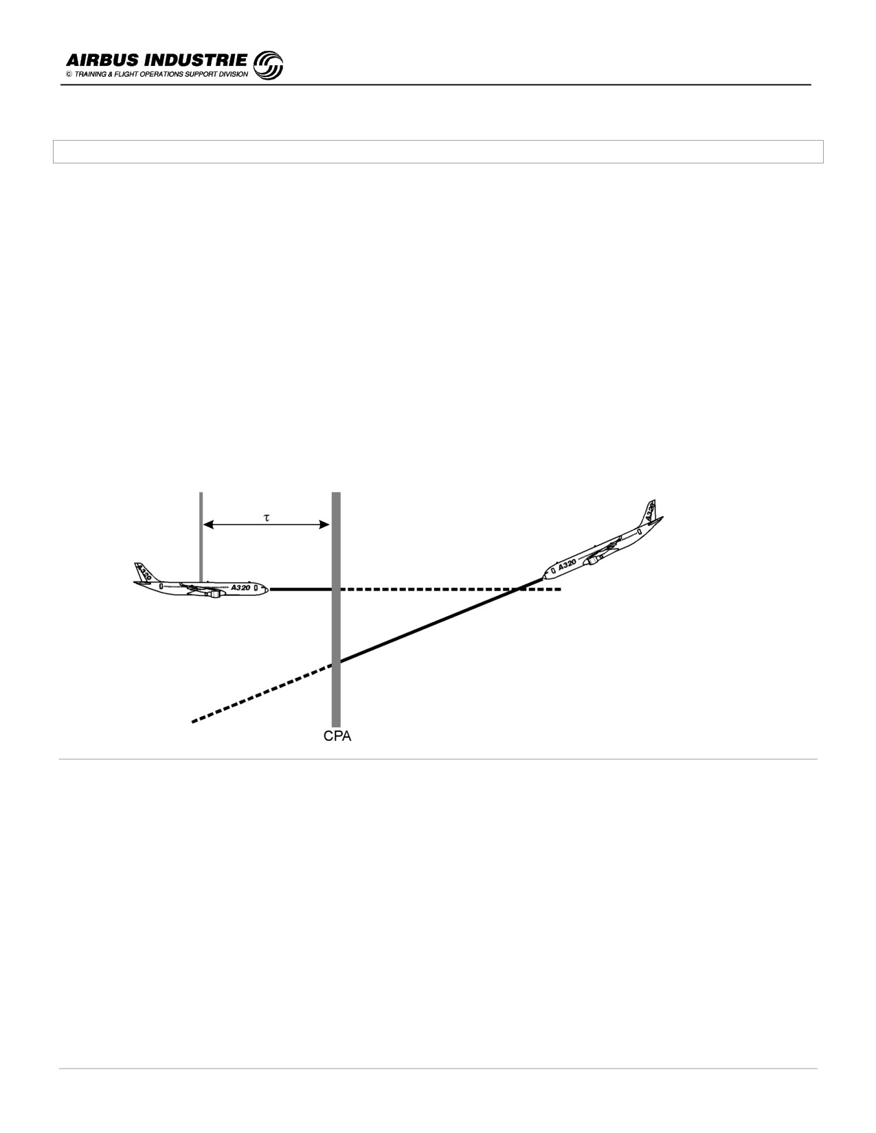
A320 INSTRUCTOR SUPPORT
NORMAL OPERATION
28 - TCAS II
1.
Some technical background
The TCAS monitors the airspace surrounding the aircraft by interrogating the transponder of other aircraft.
The reply of the transponders allow the following to be calculated:
-
the BEARING/RANGE to the intruder
-
the closure rate and
-
the RELATIVE ALTITUDE DIFFERENCE and the V/S of the intruder (if mode C-S available).
From that data, the TCAS II predicts the TIME TO (τ) and the SEPARATION AT the intruder's closest point of
approach (CPA).
If the TCAS II predicts that the SEPARATION is BELOW SAFE BOUNDARIES → TRAFFIC ADVISORY (TA) is
triggered and informs the crew that the INTRUDER is in the VICINITY.
If the TCAS II predicts a COLLISION THREAT → RESOLUTION ADVISORY (RA) is triggered to maintain a safe
separation between the aircraft. The RA is COORDINATED between the aircraft and the intruder, both using an ATC
mode S. The RAs are thus COMPLEMENTARY.
➔ In case of a RESOLUTION ADVISORY, the crew must FOLLOW IT PROMPTLY and SMOOTHLY.
The crew should NEVER MANEUVER in the OPPOSITE DIRECTION of the RA since maneuvers are
coordinated.
➔ Always attempt to VISUALLY CLEAR the airspace before maneuvering the aircraft in response to a TCAS
ADVISORY. The purpose of the TA is to advise the crew to ATTEMPT TO GET VISUAL CONTACT with the
intruder. NO EVASIVE ACTION should be SOLELY BASED on the TA.
The maximum range of intruder detection depends upon TCAS and DMC standards.
-
TCAS II maximum range is 40 NM.
-
TCAS 2000 maximum range is 80 NM.
With DMC pre V40 standard, intruder may be displayed with ND ranges selected at or below 40 NM.
DATE: JAN 2001
Page 152
UDY0102
A320 INSTRUCTOR SUPPORT
NORMAL OPERATION
With DMC V40, intruders may be displayed for any selected range; thus with TCAS 2000 up to 80 NM.
NOTE:
Some TCAS are programmed with specific aircraft limitations (max. alt. when A/C climbs at 1500 ft/mn …). Some RAs
(climb, increase climb …) are inhibited if RA maneuver cannot be achieved safely.
On some other TCAS this does not exist and has to be achieved manually by selecting TA on the Ctl panel (e.g.
Engine Out, Ldg Gear extended…), thus inhibiting RA.
NOTE:
The TCAS may work only if the intruder's A/C is equipped with a transponder; if the intruder has a Non Altitude
Reporting transponder (NAR), then only TAs may be issued based on closure rate. In that case, NAR traffic is not
displayed above 14500 ft.
NOTE:
Some TCAS are automatically set in STD BY on ground. Other TCAS are wired to INHIBIT display of traffic called "ON
GROUND TRAFFIC" (below 400 ft AGL).
When ATC is set to AUTO, when the aircraft is on ground, it still emits in mode S.
NOTE:
TCAS II can track up to 45 aircraft, display up to 30, co-ordinate up to 3 at once; this is within ± 9900 ft and 30 NM
range.
DATE: JAN 2001
Page 153
UDY0102
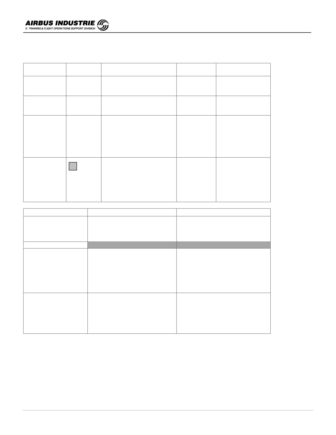
A320 INSTRUCTOR SUPPORT
NORMAL OPERATION
2.
Display of advisories, Aural messages, consequential actions
TYPE OF COLLISION
ACTION
INTRUDER
DISPLAY
AURAL
THREAT
No THREAT
◊
↑
Relative altitude > 1200 ft
TRAFFIC
- 17
Range > 6 NM
or OTHERS
(w)
NO THREAT
◊
↑
Relative altitude < 1200 ft
PROXIMATE
- 10
and Range < 6 NM
(w)
Considered as NO THREAT
TRAFFIC
τ between 20 sec
ESTABLISH
ADVISORY
•
↑
(< 550 ft) and 45 sec
VISUAL CONTACT
(TA)
- 09
(> 10000 ft)
NO EVASIVE
"TRAFFIC"
(Y)
MANEUVER
POTENTIAL THREAT
SOLELY ON
DISPLAY
↑
PREVENTIV
RESOLUTION
- 06
τ between 20 sec (>500 ft)
E "MONITOR
ADVISORY
(R )
and 35 sec (>20000 ft)
V/S"
FOLLOW RA
(RA)
+ V/S PFD
COLLISION THREAT
CORRECTIV
SHOOTHLY and
Requires ATC mode C with
E
FIRMLY
the intruder
"CLIMB,
DESCEND"
TYPE of RA
AURAL
ACTIONS
DON'T ALTER YOUR FLIGHT
PATH
PREVENTIVE RA
"MONITOR VERTICAL SPEED"
(red sector on PFD V/S)
CORRECTIVE RA
CLIMB
"CLIMB, CLIMB"
CROSS OVER CLIMB
"CLIMB, CROSSING CLIMB"
(green and red sector on PFD V/S)
V/S RECTRICTED CLB
"REDUCE CLIMB"
SMOOTHLY and FIRMLY (0.25 g)
DESCEND
"DESCENT, DESCENT"
FOLLOW GREEN SECTOR
CROSS OVER DES
"DESCENT, CROSSING
WITHIN 5 sec.
V/S RESTRICTED DES
DESCENT"
"REDUCE DESCENT"
CHANGE from CLB to
"DESCEND, DESCEND, NOW"
DES
(green and red sector on PFD V/S)
CHANGE from DES to
"CLIMB, CLIMB, NOW"
FIRMLY (0.35 g) FOLLOW GREEN
CLB
SECTOR WITHIN 2.5 sec
INCREASE CLB (DES)
"INCREASE CLIMB (DESCENT)"
RATE
The TAs and RAs are provided when the relative altitude between two aircraft are:
- less than respectively 850 ft / 750 ft below FL300,
- less than respectively 1200 ft / 800 ft above FL300.
When clear of conflict, "CLEAR OF CONFLICT" aural message comes up; if initially in level flight, or in climb, or in
descent, resume initial conditions unless otherwise advised by ATC.
NOTE:
All RAs are converted to TAs below 500 ft AGL. TA aural is inhibited below 400 ft AGL.
DATE: JAN 2001
Page 154
UDY0102
A320 INSTRUCTOR SUPPORT
NORMAL OPERATION
3.
Specifics of the control boxes
Mode selector
TA
TA ONLY on ND. RAs are converted into TAs.
TA triggered when τ < 20 sec regardless of altitude.
GPWS, Stall warnings, windshear warning have priority.
TA/RA
All intruders and advisories provided if ATC is ON and ALT RPT is ON.
Traffic Selector
THRT
Non Threat and Proximate intruders displayed only if at least one TA/RA is triggered.
ALL
Non Threat and Proximate intruders FULL TIME displayed within ± 2700 ft.
ABV/BLW Non Threat Traffic displayed within ± 9900ft, ± 2700 ft (e.g. ABV: if + 9900 ft, - 2700 ft).
4.
Procedures
-
In climb select ABOVE.
-
In cruise select ALL or BELOW if cruise altitude within 2000 ft from FL410.
-
In descent select BELOW.
-
In heavy traffic TMA select THRT.
-
In specific cases such as landing on converging runways or take off towards an identified traffic, flying towards
an area where undesired RA will be triggered, select TA.
-
In case of ENG failure or A/C degraded performance select TA.
-
Once the aircraft is on ground, set TCAS to OFF (with transponder to AUTO and aircraft on ground, mode S is
still transmitted; thus the TCAS of the aircraft in flight detect the signal from the aircraft on ground).
DATE: JAN 2001
Page 155
UDY0102

A320 INSTRUCTOR SUPPORT
NORMAL OPERATION
In case of a TA, always attempt to visually clear the airspace before maneuvering the A/C. Else no
evasive maneuver based solely on TA displayed on ND.
With a TA, it is a good practice for the PF (or Cpt) to announce to the PNF or (F/O) "I have
controls, you watch outside".
In case of PREVENTIVE RA "Monitor Vertical Speed"
-
maintain Flight Path and keep V/S out of Red Sector.
In case of CORRECTIVE RA "CLIMB" "DESCENT"
-
Smoothly and promptly react HAND FLYING to follow Green V/S Sector
-
Set AP and ATHR OFF - maneuver 0.25 g maximum.
In case of CORRECTIVE RA "CLB (DES) NOW" "INCREASE V/S
-
Firmly HAND FLY the V/S Green Sector (AP and ATHR OFF 0.35 g).
-
Set AP and ATHR OFF - maneuver 0.35 g maximum.
In case of "CLIMB" "CLIMB NOW" "INCREASE CLIMB" in Final Approach - GO AROUND.
In all cases try to establish visual contact and advise ATC.
When "CLEAR of CONFLICT" resume level flight, climb or descend unless otherwise directed
by ATC.
NOTE:
A new version of TCAS II is now available and called TCAS II change 7.
It includes the following improvements:
• All TAs aural are inhibited below 500 ft AGL (instead of 400 ft, for consistency with the logic of RA reversion to TA
at 500 ft).
• Multi aircraft management is improved especially during climb and descent (up to 30 aircraft).
• Covers the cases where the intruder does not follow an RA.
• Suppresses nuisance RAs at higher altitudes, thus allowing proper RVSM operation (TA - RA triggered if ∆ ALT
less than respectively 850 ft / 700 ft up to FL 420).
• RA aural warnings are more explicit:
-
Preventive RA: “monitor V/S" is changed to "maintain V/S maintain"
or "maintain V/S crossing, maintain".
-
Corrective RA: "Reduce Climb" or "reduce Descent" is changed to
"adjust V/S adjust".
• The preventive RA on PFD is more explicit by providing a Green band, which justifies the change in the aural RA
warnings.
• Finally surveillance is increased to 10.000 ft.
• The TCAS signal emitted by aircraft on ground are automatically eliminated.
DATE: JAN 2001
Page 156
UDY0102

A320 INSTRUCTOR SUPPORT
NORMAL OPERATION
29 - USE OF RADAR
!
Technical Background
The latest radars transmit at extremely high frequencies in the X band (8 to 12.5 khz); this makes it possible to build
highly directional antennas, small enough to fit in the nose cones of the A/C. The characteristics of such X band radars
are: GOOD RESOLUTION - GOOD RETURN.
The latest radars have 2 functions: WEATHER DETECTION / AVOIDANCE and MAPPING.
The mapping function is secondary. It uses a PENCIL BEAM which allows a larger range than a FAN BEAM. The
pencil beam is such that ground targets which generate LARGE DIFFERENCES IN SIGNAL are easily mapped
(mountain, cities, coast lines…), whereas those which generate EVEN DIFFERENCES IN SIGNAL are difficult to
resolve (calm sea, even ground).
The Weather Radar (WX) detects PRECIPITATION DROPLETS: RAIN DROPS / WET HAIL / WET SNOW / WET
TURBULENCE etc.
The strength of the echo is a function of the drop size, composition and amount. Water particles reflect 5 times as
much as ice particles of the same size.
Consequently CLOUDS/FOG/CLEAR AIR TURB/LIGHTHING/WIND… are NOT detected by radar.
THE WEATHER RADAR IS TO BE USED
TO DETECT/ANALYZE/AVOID SIGNIFICANT WEATHER.
It is NOT a PILOT OPERABLE TERRAIN or COLLISION
AVOIDANCE SYSTEM.
The pilot has several tools to operate the radar:
-
the TILT of the antenna,
-
the GAIN of the receiver (automatic or manual) and
-
the MODE of operation (WX, WX + T, MAP).
Some radars provide a Ground Clutter Suppression function which is operative in WX mode and suppresses 85% of
stationary targets or ground targets - GCS.
Some radars provide RCT function which is used temporarily to help to detect weather or build ups presence BEYOND
existing detected weather.
EFFECTIVE TILT MANAGEMENT IS THE SINGLE, MOST EFFECTIVE KEY TO GET A MORE
INFORMATIVE WEATHER RADAR DISPLAY.
The antenna is stabilized. The angle between the weather radar antenna and the local HORIZON is the TILT.
When the pilot selects a TILT ANGLE on the radar CTL PNL, displayed on ND, this angle is the one between THE
RADAR ANTENNA AND HORIZON REGARDLESS of THE A/C PITCH/BANK if within the stabilization limits (typically
± 15° pitch, ± 35° bank).
The stabilization of the antenna is achieved using IRS data.
DATE: JAN 2001
Page 157
UDY0102

A320 INSTRUCTOR SUPPORT
NORMAL OPERATION
The WET TURBULENCE is characterized by a wide velocity variance between the rain drops.
The return velocity variance of the droplets is measured by the Doppler principle. Indeed the velocity variance of the
droplets creates a return signal frequency shift due to the relative motion between the A/C and the droplets.
When the shift is beyond a given threshold, turbulence is detected.
TURBULENCE CAN BE DETECTED UP TO 50 NM, ONLY IF WET.
The GAIN CONTROL is mostly used in AUTO or CAL.
However the analysis of weather, or the adjustment of map returns may require a JUDICIOUS use of Gain.
IN WEATHER MODE, DETECTION OR EVALUATION OF BUILD UP SHALL ALWAYS START
IN AUTO/CAL GAIN MODE.
IF GAIN IS THEN USED MANUALLY FOR DEEPER ANALYSIS OF WEATHER IT MUST BE
RESET TO AUTO/CAL ONCE ANALYSIS COMPLETED.
The gain reduction allows the detection of the strongest part of a cell displayed in red on ND. Indeed by slowly reducing
the gain, the red areas (level 3 return) slowly turn into yellow areas (level 2 returns), while yellow areas turn into green
ones (level 1 return).
The red area which is the latest to turn into yellow is the strongest part of the build up. THIS STRONGEST AREA HAS
TO BE AVOIDED BY THE GREATEST DISTANCE.
!
Some Weather Considerations
An FAA advisory circular regarding thunderstorms (AC 00-24B) provides most valuable guidelines on how to fly with
regard to thunderstorms.
"Thunderstorms gather every weather hazard known to aviation in one vicious bundle".
-
Squall lines (narrow band of active thunderstorms usually ahead of a cold front in moist and unstable air -
maximum activity late afternoon).
-
Tornadoes (violent thunderstorms draw air into their cloud bases with great vigor. If the incoming air has an
initial rotation motion, this creates an extremely concentrated vortex from surface well into cloud).
+
An aircraft entering a tornado is almost certain to suffer structural damage even in the hidden part of the
tornado within the cloud (violent turbulence, dust, debris…).
-
Turbulence (strongest gusts/turbulences occur with shear between updrafts and downdrafts.
Shear turbulence is encountered up to 5000 ft above a thunderstorm and 20 NM laterally. In low altitude, gusts
front move far ahead of the rain fall - 15 NM).
+
It is almost impossible to maintain constant altitude in a storm. Allow altitude to "ride the waves".
-
Icing (updraft carry large amount of large droplets, up above the freezing level to -16° C. Below that temperature
most of the supercooled water sublimates into ice crystals. As for the supercooled water itself, it freezes
immediately on impact to an aircraft).
+
Clear icing occurs very rapidly in thunderstorms where OAT is between 0° and - 15° C.
DATE: JAN 2001
Page 158
UDY0102
A320 INSTRUCTOR SUPPORT
NORMAL OPERATION
-
Hail (the supercooled droplets which turn into ice crystals, get bigger and bigger as they encounter other
droplets. They get bigger and bigger and can be thrown several miles ahead of a dark storm cloud, in clear air.
As they fall, they melt and you get a mixture of rain and hail).
+
Hail is one of the worst hazards in a storm. It can be expected in the cloud, and in clear air ahead of a storm
below the anvil.
-
Low ceiling and visibility (in the cloud and in precipitation).
Precision instrument flying is almost impossible below storms because of all packed hazards.
-
Effect on altimeters (pressure falls rapidly with the approach of a storm and rises sharply with gusts).
+
Errors can reach 100 ft.
-
Lightning (intensity and frequency have no simple relationship with other storm parameters).
+
Lightning can puncture the skin, damage communication/nav systems, ignit fuel, cause errors on magnetic
compass, blind the pilot.
-
Engine water ingestion (engine may ingest only a small amount of water; beyond that amount, it can cause flame
out, stall, structural failures which are favored by thrust changes).
+
Establish constant thrust setting when closing up a storm or heavy turbulence.
To standardize "thunderstorm" language between a weather radar operator and pilots, the use of VIDEO
PROCESSOR LEVELS (VIP) is promoted.
The radar echo intensity levels are scaled from 1 to 6 for radar observers:
VIP 1
Weak,
VIP 2
Moderate = light to moderate turb + possible lightning,
VIP 3
Strong = severe turb possible, with lightning,
VIP 4
Very strong = severe turb likely with lightning,
VIP 5
Intense = severe turb likely, lightning, hail likely, wind gusts and
VIP 6
Extreme = severe turb, lightning, large hail, surface wind gusts + turb.
Thunderstorm build up and dissipate rapidly ⇒ DO NOT PLAN A COURSE BETWEEN ECHOES.
Use GROUND RADAR data to determine the areas of echoes to be avoided.
Use AIRBORNE RADAR to analyze and actually avoid build ups; use visual cues whenever available. PLAN THE
AVOIDANCE EARLY ENOUGH between 100 NM to 50 NM from an echo.
Be aware THAT THE RADAR MAY BE CLEAR OF ECHOES BEHIND A BIG ECHO which masks existing build ups
(use of RCT).
Be aware THAT THE RADAR MAY BE CLEAR BETWEEN ECHOES. DO NOT GO IN BETWEEN IF 2 MAJOR RED
and MAGENTA ECHOES ARE SEPARATED BY LESS THAN 40 NM.
Be aware THAT TOP OF BUILD UPS WITH HAIL OR WITH SMALL DROPLETS MIGHT NOT BE DETECTED OR
PROVIDE SMALL ECHOES.
Be aware THAT DRY TURBULENCE IS NOT DETECTED AND CAN OCCUR UP TO 5000 ft ABOVE BUILD UPS.
NOTE:
The LIDAR is integrated into RADAR, and it is able to detect some DRY turbulence. It emits a laser pencil beam
(length of wave 2 microns) which can be used to measure the relative motion of small dry particles by doppler effect.
The LIDAR shall be available in close future.
DATE: JAN 2001
Page 159
UDY0102

A320 INSTRUCTOR SUPPORT
NORMAL OPERATION
PILOT BEHAVIOUR WITH WEATHER
1.
AVOIDANCE RECOMMENDATIONS
-
WHENEVER SUSPECTED WEATHER, SCAN FOR IT BY VARYING RADAR TILT
-
DO NOT UNDER ESTIMATE A THUNDERSTORM EVEN IF ECHO IS WEAK (wet parts only are detected).
-
AVOID ALL CELLS RED + MAGENTA BY AT LEAST 20 NM.
-
DEVIATE UPWIND RATHER THAN DOWNWIND (less chances of turb or hail)
-
DON'T ATTEMPT TO FLY BELOW A STORM EVEN VISUAL (turbulence, shear, altimetry).
-
USE TURB DETECTION TO ISOLATE TURBULENCE FROM PRECIPITATION.
-
SEVERE TURB MAY BE ENCOUNTERED UP TO 5000 ft ABOVE A CELL.
-
STORMS WITH TOPS ABOVE 35000 ft MUST BE CONSIDERED HAZARDEOUS.
-
FREQUENT AND VIVID LIGHTNING INDICATES A HIGH PROBALIBITY OF SEVERE TURB.
2.
IN CASE OF STORM PENETRATION
-
SEAT BELTS / SHOULDER HARNESS / CABIN CREW TO YOUR SEATS / LOOSE OBJECTS SECURE.
-
ATHR OFF: SET THRUST LEVER TO TURBULENCE N1 AND PRESS ATHR I/D.
-
AP OFF IF SEVERE TURB - RELAX ALTITUDE, FAVOUR ATTITUDE.
-
COCKPIT LIGHTS FULL ON (Storm, Flood max, EIS max) WATCH INSTRUMENTS (against blindness).
-
ENG A/I ON - (be aware of potential SPD unreliable situation).
-
AVOID MOST CRITICAL ICING CONDITIONS (OAT between 0°C - 15°C).
-
Take best advantage of your radar.
AVOIDANCE RULES
DECISION TO AVOID:
NOT LATER THAN 40 NM
AVOID BY AT LEAST:
20 NM whenever possible -
5000 ft above UPWIND
Below FL 230 OAT < 0°
-
10 NM mini
Below FL 230 or OAT > 0°
-
5 NM mini
DATE: JAN 2001
Page 160
UDY0102