Airbus A320. AIRCRAFT CHARACTERISTICS AIRPORT AND MAINTENANCE PLANNING (2016-2023) - page 17
A320 INSTRUCTOR SUPPORT
NORMAL OPERATION
-
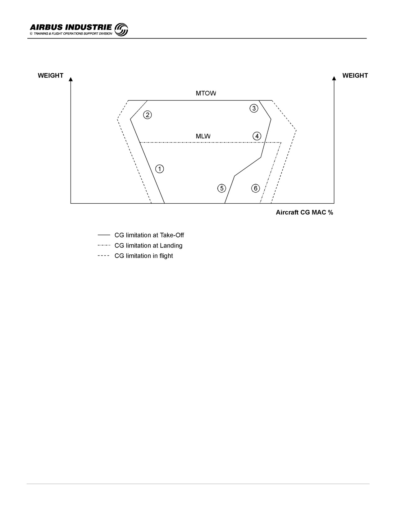
Typical resulting CG envelope:
# Performance / loading compromise at take-off
$ Nose gear strength structural limit
% Main gear strength structural limit
& Alpha floor limit
’
Nose gear adherence limit
( Alpha floor limit (landing)
The inflight limit is deduced from the take-off / Landing envelope by adding a 2% margin, provided all handling
characteristics criteria are fullfilled.
DATE: JAN 2001
Page 11
UDY0102

A320 INSTRUCTOR SUPPORT
NORMAL OPERATION
!
PF/PNF task sharing and cockpit preparation sequence and scan
The FCOM and QRH detail this essential phase of the flight. A particular geographic scan has been developed in order
to maximize the resource involvement in the spirit of ACRM. Accordingly the PF/PNF concept applies from the time the
crew arrives at the aircraft till they leave the machine. Each crew member task has specific actions intended to offer
optimal cross check and communication while efficiently achieving the desired outcome.
PF and PNF make up a team.
Consequently:
-
Preliminary cockpit check and exterior inspection by PNF.
-
PF briefs the Cabin Crew, starts the cockpit preparation and inserts the F PLN data into the MCDU. He scans
the overhead panel primarily to ensure that the IRSs are ON.
-
Once the PNF is back into the cockpit, the crew will insert perfo data in the FMS and cross check the resulting
data; then they will carry out the entire scan of the overhead panel (there is no urgency to set the Fuel Pumps
ON).
As a sum up of cockpit preparation, the crew shall keep in mind that this phase of the flight is never a quiet phase.
Many people get into the cockpit, the PNF goes for the external inspection while the PF programs FMS. Once PF and
PNF are both in their seats they have to inform each other of their mutual actions so as to be fully in the loop:
→ PNF advises PF of the result of the external inspection,
→ Both review the OVHD panel,
→ Both review the essential data inserted in the MCDU,
→ Both review the EIS Ctl panel (Range, mode, CSTR) and FCU (initial expected target altitude),
→ Both review EIS: PFD - ND (SID in plan),
→ Both review ECAM (amongst others Oil, Hyd, Fuel gauges) and
→ Both review the Pedestal (PKG brake, RMP …).
DATE: JAN 2001
Page 12
UDY0102

A320 INSTRUCTOR SUPPORT
NORMAL OPERATION
3 - TAKE OFF BRIEFING
The main objective of the Take off briefing is for the PF to inform the PNF of his intended course of actions during Take
off and initial climb, in normal and abnormal situations. It may be completed by specific Captain’s instructions. Any
misunderstanding shall be clarified through questions.
The briefing must be PRAGMATIC, that is to say adapted to the take off actual conditions; it must be SHORT and
covered in a LOGICAL manner.
When specific data is reviewed (V speeds, FLX, LDG ELEV, SID …) it shall be cross-checked on the associated
peripheral (PFD, ECAM, ND and MCDU).
!
The following KEY ITEMS shall be mentioned:
1. Normal situation
-
All PERF T/O DATA: V1/VR/V2 - FLEX - CONF - THR/ACCEL ALT - PACKS.
-
Specific runway / weather condition. Use of Anti Ice (A/I).
-
Key items of ATC clearance - initial cleared altitude and trajectory.
-
Transition altitude - MSA - Constraining SID ALT CSTR if any.
-
Use of the Radar …
-
Reminder of major NOTAM, MEL or CDL item.
2. Abnormal situation (EO at take off)
-
Who calls STOP; who actually STOPS the A/C.
-
EO ACCEL ALT
-
Minimum initial climb altitude (MSA, Circuit pattern altitude …).
-
Expected procedure (left/right down wind, radar vector to runway, …).
-
Potential overweight landing with associated configuration (to be checked in QRH).
Such a briefing shall be done without rush, when the workload is low so that it enables to the pilots to properly
concentrate.
Therefore it will be done once FMGS, FCU etc. … are properly programmed and set, close to the end of the cockpit
preparation and before the engine start.
Should the take off conditions change after engine start, then a short briefing concentrating on the main changes will
be carried out: e.g. V speeds / FLX / CONF - Trajectory - Altitudes.
DATE: JAN 2001
Page 13
UDY0102

A320 INSTRUCTOR SUPPORT
NORMAL OPERATION
4 - ENGINE START
The normal engine start procedure is the AUTO START procedure; the MANUAL START procedure is used
exceptionally in specific cases. During an AUTO START procedure the FADEC protects the engines against HOT,
HUNG START, START STALL …, it detects these phenomena and takes the appropriate action (reducing the fuel flow,
or cutting it off, cranking the engine, attempting a new start etc. …). This significantly saves engine life time.
The engines are started in sequence, preferably engine 2 first.
!
AUTO START
-
Check thrust levers are at Idle.
-
Set IGN/START to START. Check amber crosses disappear on ECAM E/W-D and APU bleed pressure stable.
-
Set ENG 2 MASTER ON.
-
Check in order:
STARTVALVE OPENS → N2 → IGN A (B) → FUEL FLOW → EGT → OIL PRESS rising.
ONCE START VALVE CLOSES → Note PEAK EGT, and Eng Vibration → Parameters stabilized.
-
Then repeat for ENG 1.
For IAE engines a 30 sec crank phase is systematically applied by FADEC before IGN and FUEL FLOW in order to
avoid rotor bow.
Remarks:
-
If the thrust lever is not at idle at engine start, an ECAM alert will be triggered requesting lever to be set at idle.
Failing to comply might be hazardous since the engine will accelerate rapidly to the thrust determined by the lever
position.
-
When both engines have been started, set the IGN / START switch back to NORM, to allow PACKS to be back
ON.
-
Once the engines are started, set APU BLEED to OFF to prevent engine exhaust gas re-ingestion.
-
In case of any abnormal during ENG START, follow the ECAM and do not interrupt the FADEC protective
actions by non-requested actions on START panel.
!
MANUAL START
Manual start is to be used exceptionally in case of STARTER VALVE problems or low EGT margins or in case of high
residual EGT or to CRANK the ENG DRY (e.g. to get EGT down) prior to sending fuel ON; it may be recommended for
high altitude operation.
Manual start of the engines is also recommended after aborting a start because of an engine stall, or engine EGT
overlimit, or low start air pressure. Consider dry cranking the engine 30 sec after an aborted start.
During MAN START the FADEC ensures a PASSIVE monitoring of Engine parameters, with potential warnings. The
starter is automatically cut off at about 50% N2.
DATE: JAN 2001
Page 14
UDY0102
A320 INSTRUCTOR SUPPORT
NORMAL OPERATION
Furthermore, the starter engagement is limited in time and in number of successive attempts:
-
CFM: 4 times 2 mn with 20 sec between each start.
-
IAE: 2 times 2 mn + 1 time 1 mn with 15 sec between each start.
-
This is the reason why the use of the stopwatch is recommended.
-
Check that Thrust Levers are at Idle.
-
Select IGN / START switch to START. Check amber crosses disappear on ECAM E/WD and APU BLEED
pressure stable.
-
Press the MAN START P/B on the overhead panel; START STOPWATCH (for monitoring the start cycles, if
applicable, at least) and check:
• START VALVE OPENS → N2 rising.
• When N2 ≥ 20 % (max motoring speed recommended), MASTER ON and check.
• IGN A (B) → FUEL FLOW → EGT → OIL PRESS rising.
• AT N2 > 50 % START VALVE closes (check time), set MAN START OFF.
• Note PEAK EGT and Engine Vibrations → Parameters stabilized
Then repeat for the other engine.
Remarks:
-
When both engines have been started, set the IGN START switch back to NORM.
-
Finally it is good to keep in mind the average IDLE parameters which are:
N1 ≈ 20% - N2 ≈ 60% - EGT 400° C - FF 300 kg/h
for IAE engines EPR ≈ 1.01.
!
Tail pipe fire
In the event of a second engine start attempt, a tail pipe fire may occur. In such a case:
-
Shutdown the affected engine using the Eng Master switch; (do not use the FIRE P/B, nor the Engine Fire
Extinguishing bottles).
-
Crank the engine using APU or opposite engine bleed air.
Refer to p 79 for tail pipe fire details.
DATE: JAN 2001
Page 15
UDY0102

A320 INSTRUCTOR SUPPORT
NORMAL OPERATION
5 - TAXI AND BRAKING
Before taxiing, check NW STREERG DISC amber MEMO is not displayed on ECAM to confirm NWS is available.
During taxi, there are several issues: taxi roll and steering, braking.
!
Taxi roll and steering
In order to initiate the taxi roll, the use of minimum thrust is recommended to avoid FOD (N1 40 % max).
Taxi with APU BLEED OFF (APU bleed valves closed - engine bleed valves open) to avoid ingestion of exhaust gases
by the air conditioning system.
The Nose Wheel Steering is « by wire »; the relationship between the tiller and the nose wheel angle is not linear, but
the force on the tiller is light and independent of the deflection.
80
70
60
50
40
30
20
10
0
0
20
40
60
80
TILLER
The pedals do control the nose wheel steering at low speed (± 6 ° with full pedal deflection).
-
Consequently when you taxi on straight taxiways and on shallow turns, use the pedals to steer the aircraft keeping
a hand on the tiller.
-
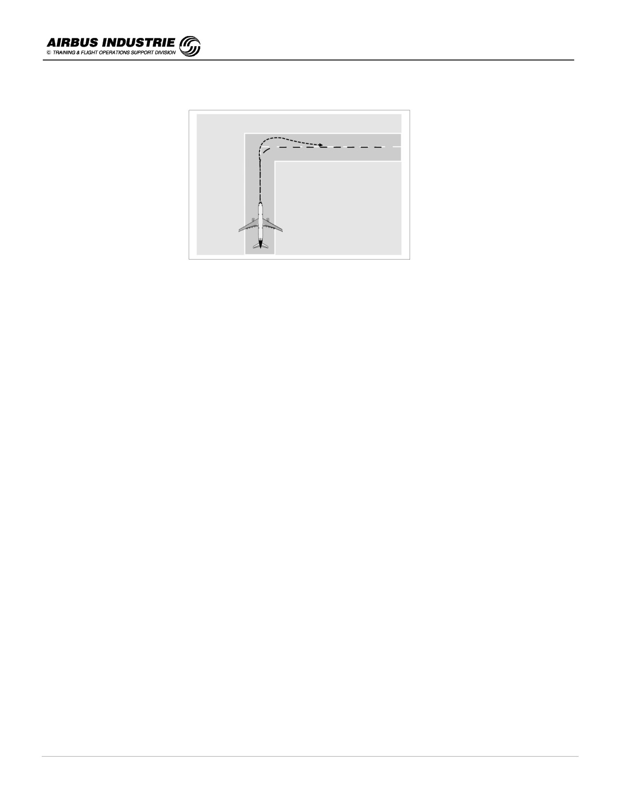
In sharper turns, use the tiller smoothly and progressively: a rapid movement on the tiller does not induce a very
rapid movement of the steering mechanism which is limited to approx. 12 °/sec per inertia.
Conversely, if a big input has been set on the tiller, avoid trying to adjust to a lower setting which often causes
uncomfortable oscillations; keep this tighter turn and steer out a little earlier.
When exiting a sharp turn, anticipate the steer out.
If both pilots act on the tiller or pedals their inputs are added, till the maximum value of steering angle programmed
within the BSCU.
On wet or contaminated runways, taxi with reduced speeds; avoid large tiller inputs in case of skidding. Take benefit
of differential engine thrust for shallow turns, as well as of smooth differential braking which might be more efficient
than the nose wheel steering.
DATE: JAN 2001
Page 16
UDY0102
A320 INSTRUCTOR SUPPORT
NORMAL OPERATION
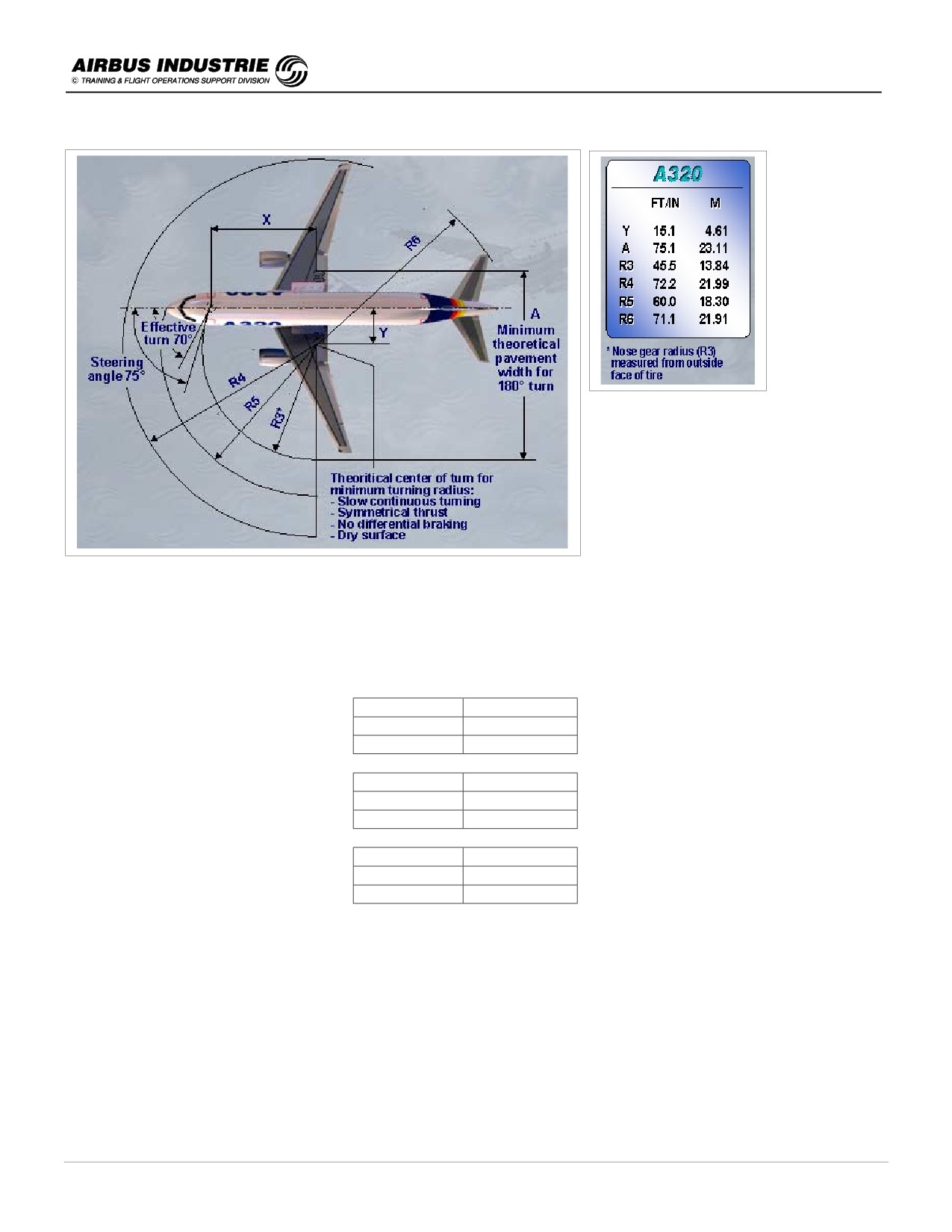
Minimum Turn Radius (assuming symmetrical thrust and no differential braking).
The figures are provided for A320-200.
The minimum runway width (pavement) required for 180° turns is 30 m (99 ft). The turn application assumes
symmetrical thrust and no differential braking. The specific 180° turn procedure is described in A320 FCOM 3.03.10.
-
Nose radius:
-
A319
-
16.6 m
-
A320
-
18.3 m
-
A321
-
22.5 m
-
Tail radius:
-
A319
-
19.8 m
-
A320
-
21.9 m
-
A321
-
24.2 m
-
Wing Tip radius:
-
A319
-
21.4 m
-
A320
-
22.1 m
-
A321
-
22.1 m
Effective steering angle: 75°.
DATE: JAN 2001
Page 17
UDY0102
A320 INSTRUCTOR SUPPORT
NORMAL OPERATION
OVERSTEERING TECHNIQUE
For A 321 (longer a/c), it may be necessary to consider oversteering technique, main gear being 20 m behind the pilot.
In case of a 180° turn on the runway a specific procedure is provided in SOP. Keep in mind that:
-
You should not let the G/S drop below 8 kts during the maneuver in order to avoid stopping.
-
You may use differential thrust setting, by adding thrust on outer engines (≅ 50 % N1).
-
The use of differential braking is not recommended due to gear stress.
Finally on wet or contaminated surfaces, more specifically when turning on the runway white or yellow painted
markings, tight turns lead to jerky rides of the nose wheel which are noisy and uncomfortable.
!
Braking
The brakes are carbon brakes. They have twice the life of steel brakes and they weigh less than steel brakes. Carbon
brakes are tolerant to thermal overloads and they maintain maximum torque capability at high temperatures. They do
not weld as steel brakes. Their maximum temperature is limited by adjacent component heat capacity (e.g. hydraulic
fluid inflammation temperature). Their efficiency improves slightly with wear; they do not melt. But considerable wear
and rise in temperature occur during taxi due to successive brake applications; at each brake release there is a small
amount of oxidation of the surface which is removed at next brake application.
The brake wear check is done during External Inspection with Parking Brake set ON.
However the brake temperature should not generally rise above 150° before T/O for proper RTO. Thus consider
using brake fans during taxi, if temperature gets close to that value. Don't use brake fans during T/O.
As a general rule, don’t ride on the brake; let the speed increase to around 30kts in straight lines and then press
smoothly the pedals to reduce speed down till GS 10 kts and release.
When you reach a sharp turn, press the pedals smoothly to bring the speed down to 10 kts.
DATE: JAN 2001
Page 18
UDY0102
A320 INSTRUCTOR SUPPORT
NORMAL OPERATION
Parking brake particulars:
-
Note that, when the parking brake is ON, pressing on the pedals has no effect on the braking. Consequently if for
any reason the aircraft moves forward while parking brake is ON, the parking brake must be released in order to
get braking efficiency from the pedals (on latest A320s, a modification provides the availability of pedal braking
even if parking brake is ON).
If the ACCU PRESS drops to 1500 PSI, be aware that loss of efficiency of the parking brake can be sudden. Before
taxiing, the brakes must be checked; this check consists in verifying that the Normal braking has actually taken over
when parking brake is off, and thus that both BRAKE yellow pressure indications remain at 0 when pedals are pressed.
The most comfortable way to carry out this check is:
-
while parking brake is ON, press pedals down and
-
release the parking brake and check that both BRAKE yellow pressure indicate 0.
Another method consists in releasing the parking brake, in order to set the aircraft moving; then the pilot presses the
pedals smoothly. He checks:
-
the aircraft decelerates gently,
-
the Yellow brake pressure indicates 0 on both gages of the indicator.
Be aware of Passenger comfort.
If any braking problem is encountered during taxi, set the A/SKID - NWS switch to OFF with no pedal braking. Then
use pedal braking with care by modulating the pressure.
NWS is then lost as well, thus use differential braking to steer the aircraft.
Other drills:
-
After start up or during taxi, PF has to check the Flight Controls; he will successively move the stick and rudder
pedals while watching outside the aircraft during straight line taxiing (or when A/C is stopped); while moving the
pedals he will simultaneously press the pedal disconnect P/B on the tiller with the palm. PNF will check the proper
movement of the surfaces on the ECAM. PF must keep head up during the check.
-
The PNF has merely to move his stick to ensure that those inputs are transmitted to the associated surfaces
and that the stick is “free”, he checks the stickcross movement on PFD.
The purpose of this check is thus different from the one of the PF Flight Control check.
-
If the ATC modifies the clearance, this must be reflected on MCDU, FCU and possibly RMP; a short briefing shall
confirm those modifications.
-
If the T/O has to be achieved with PACKS OFF for performance reasons, APU BLEED may be used with PACKS
ON if Air conditionning is desired; this allows to maintain the required engine performance level and passenger
comfort. In case of APU auto shutdown during T/O, the engine thrust is frozen, till the thrust is manually reduced;
the PACKS revert to engine bleed which causes an increase of EGT to keep the N1 (EPR) target.
If the T/O is performed with one PACK unserviceable, the procedure states to set the failed PACK to OFF. The T/O
may be performed with the other PACK ON (if performance permits), with TOGA or FLX thrust, the PACK being
supplied by the onside Bleeds. In this asymmetric bleed configuration, the N1 take off value is limited to the value
corresponding to the Bleed ON configuration.
DATE: JAN 2001
Page 19
UDY0102
A320 INSTRUCTOR SUPPORT
NORMAL OPERATION
6 - TAKE OFF
The take off is actually divided into various sequences:
!
Take off initiation and power set:
-
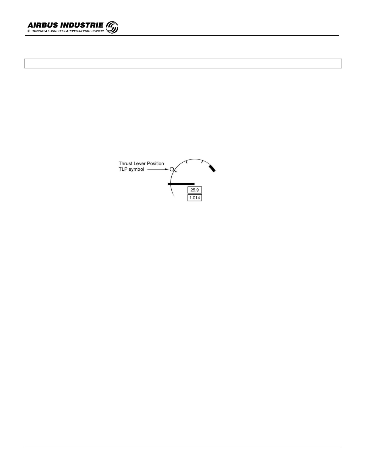
Set the power in 2 steps in case of headwind and crosswind till 20 kts:
• bring thrust levers to 50 % N1 (1.05 EPR) position using the thrust lever symbol on the N1 (EPR) gauge.
• wait till all engines are set to 50 % N1 (1.05 EPR) and stabilized.
• then bring thrust levers to FLX or TO notch in one movement.
• keep half stick forward till 80 kts and then release it progressively to neutral by 100 kts.
-
Set the power in 3 steps in case of tailwind or strong crosswind:
• bring thrust levers to 50 % N1 (1.05 EPR) position on the 2 engines,
• then move thrust levers to 70% N1 (1.15 EPR) rapidly,
• set TO or FLX TO progressively, to reach the thrust by 40 kts G/S,
• keep full stick forward till 80 kts and then release it progressively to neutral by 100 kts,
This ensures that all engines will accelerate similarly and efficiently.
Then check:
• the FD pitch bar (and yaw bar if ILS avail),
• the FMA (to be announced by PF and checked by PNF),
• the position update on the ND (A/C symbol on RWY threshold),
• the power setting (Actual N1/EPR = N1/EPR rating limit before 80 kts, announced by PNF),
Note that:
-
Rolling take off is recommended whenever possible.
-
If the thrust levers are not set to the proper T/O detent (e.g. in FLX instead of Max T/O), a message comes up on
the ECAM. Push thrust levers full forward.
-
If ATC requests you to maintain runway center line, simply turn the HDG selector and, select the most probable
HDG target expected. NAV mode will disarm and RWY TRK mode will engage on FD after lift off and will guide
the A/C on the runway center line.
-
During initial roll, stick shall be pushed halfway forward in most cases, to improve NLG adherence with ground.
DATE: JAN 2001
Page 20
UDY0102
A320 INSTRUCTOR SUPPORT
NORMAL OPERATION
!
Take off roll:
-
Use the rudder pedals to steer the A/C. The NWS will be effective till 130 kts. Don’t use the tiller beyond 20 kts.
-
Avoid using the stick into wind; indeed this increases the natural tendency of the a /c to turn into wind.
-
In case of low visibility take off (RVR down to 125 m) visual cues are the primary means to track the runway
center line. If an ILS is available on departure runway, the PFD yaw bar provides an assistance in case of fog
patches.
!
Rotation:
-
Pull on the stick smoothly to ensure a continuous rotation rate (typically 3 °/s).
-
Avoid being aggressive on the stick, or adding sudden stick input when the A/C pitch reaches around 8°, so
as to avoid tailstrike.
-
Rotate initially to target pitch 10°; once airborne adjust the pitch to the FD bar pitch (SRS order). The FD does not
provide a rotation rate order, but a pitch order to fly the T/O speed profile once airborne.
-
Keep the stick laterally centered during the rotation, then keep wings level.
-
Once airborne the FD lateral bar will come up automatically.
-
AP is available 5 sec after lift off (100 ft).
NOTE:
The AP/FD SRS mode ensures a pitch guidance at Take-Off or Go-Around, so as to provide a safe and efficient pitch
control in this touchy phase.
In order to simplify its description, it is said that with all engines operative, the SRS commands a pitch leading to an
IAS = V2 +10 and, that with one engine inoperative, it commands a pitch leading to an IAS = V2. This description is
schematically true.
Actually, at take-off, the SRS uses as a computation target V2+10, with all engines operative (AEO), the aircraft speed
at the time of failure limited to V2 and V2+15 with one engine inoperative (OEI).
The FG then computes the pitch command which full fills following objectives and is the minimum of:
-
pitch to get V2 + 10 with AEO, or the OEI speed,
-
maximum pitch: 17.5º,
-
pitch required to climb with a minimum climb gradient of .5º, limited to 22.5º.
This explains why, in many take-off cases, the IAS which is actually flown is neither V2 + 10 (AEO) nor V2 (OEI).
Once again, the take-off SRS mode provides a pitch command to fly a given speed schedule during the take-off
segments, but is not intended to provide a pitch rate command during rotation.
DATE: JAN 2001
Page 21
UDY0102
A320 INSTRUCTOR SUPPORT
NORMAL OPERATION
!
Tail strike considerations: Refer to FCOM bulletin 22 for briefing about tail strikes:
CONDITION
TAILSTRIKE PITCH ATTITUDE
LANDING GEAR
COMPRESSED
EXTENDED
A319
13.9 °
15.7 °
A 320
11.7°
13.7°
A 321
9.7°
11.4°
The recommended flap configuration to provide best tail clearance at take off is CONF 2. It is therefore to be used
whenever performance allows, considering furthermore that when CONF 1 + F is chosen, take off close to V2 mini may
have to be achieved.
In order to avoid tail strike, rotate at VR (not before!) and control a constant/smooth rotation rate without any
aggressive or abrupt aft action on the stick more specifically when a positive attitude is already achieved.
In case a tail strike occurs, consider a landing at the nearest airport (origin for example) for inspection purposes. If
however in such conditions the A/C has to climb, consider not pressurizing.
!
Thrust Reduction / Acceleration:
Usually THR RED ALT = ACCEL ALT; it is defaulted to 1500 ft AGL in FMS but modifiable by the pilot as required by
the procedure (e.g. noise abatement).
Reaching THR RED ALT, LVR CLB comes up on FMA; bring the thrust levers back into CLB detent.
• Note that if FLX TEMP is very high, FLX N1 (EPR) is close to CLB N1 (EPR) but never below.
• When THR LVRs are set in CLB detent, ATHR is ON. If SRS mode is still engaged, the FD pitch bar will order
a pitch down depending upon the amount of thrust decrease in between TOGA or FLX TO and CLB thrust.
When handflying, follow the pitch down order.
Reaching the ACCEL ALT, the target speed is set automatically to initial climb speed.
• Note that there is a significant pitch down order on the FD bar.
• Retract Flaps when IAS ≥ F with a positive speed trend.
• Retract Slats when IAS ≥ S with a positive speed trend.
• On A321, if the Take-off is achieved at high GW, S speed is above VFECONF1+F. In that case:
-
accelerate towards S; at 210 kts the Flap autoretraction system retracts the Flaps to 0 and VFE on
PFD goes to VFECONF1 230 kts.
In that case, should the IAS drop back below 210 kts, flaps will not extend back to 1 + F.
NOTE:
If the FCU ALT is low, ALT* will engage rapidly after lift off, before the A/C reaches THR RED or ACCEL ALT. In that
case, LVR CLB comes up on FMA and target speed goes to initial climb speed.
The same will happen if the pilot manually pulls OPEN CLB or V/S.
In many cases, THR RED ALT = ACCEL ALT. Thus the LVR CLB message comes up simultaneously on the FMA with
CLB (OPCLB) mode, and target speed increases. In that case, when hand flying the aircraft, follow the FD pitch down
order first, and then set THR LVRs into CLB detent.
DATE: JAN 2001
Page 22
UDY0102

A320 INSTRUCTOR SUPPORT
NORMAL OPERATION
!
Other drills in take off:
-
On the EFIS Control panel, select CSTR.
-
If the A/C is TCAS equipped, select ABV (if available).
-
If there is weather, use the radar and set TILT + 4°.
-
If there is terrain around the airport or along SID, set TERR ON ND to ON to allow EGPWS display.
-
If PACKS are set to OFF at take off, select them back ON only once thrust is reduced in order to avoid potential
resulting EGT increase.
Set them back ON sequentially to improve PAX comfort (∆t ≅ 10 sec), as per FCOM procedure.
-
In case of crosswind take off, keep the runway center line using the rudder pedals but NOT the tiller.
Avoid setting the side stick into wind, which increases the natural tendency of the A/C to turn into wind.
-
At rotation, laterally center the side stick.
-
During take off roll, try to roll the aircraft with the nose wheel away from the runway centerline lights so as to
minimize the resulting jerks and noise.
NOTE:
The FADEC operates with its own temperature sensor. If, in hot weather, the sensor heats up, its detected temperature
could be higher than TFLEX (e.g. OAT 35°, TFLX 40, sensor temp 45°). Once the engine rotates and the aircraft
taxies, the sensor temperature will slowly become equal to OAT.
However, as long as sensor temperature is higher than TFLX, the N1 (EPR) limit value provided by the FADEC and
displayed on ECAM E/W Display is TOGA.
NOTE:
Reminder of some characteristic speeds.
A319
A320
A321
SPEED
CFM
IAE
CFM
IAE
CFM
IAE
A319-115
A319-132
A320-212
A320-233
A321-211
A321-231
VMCL
110
108.5
108
109
114
114
VMCA
114.5
109.5
110.5
111.5
114
114
VMCg
CONF 1+2/
113.5
107.5
110.5
112.5
104.5
109
CONF 2
* VLS is limited by VMCA at T/O; by VMCL in all other phases.
* VMCA, VMCL, VMCg, varies also with altitude.
A319 - 115
CFM56 - 5B7
A319 - 132
IAE V2524 - A5
A320 - 212
CFM56 - 5A3
A320 - 233
IAE V2527 - A5
A321 - 211
CFM 56 - 5B3
A321 - 231
IAE V2533 - A5
DATE: JAN 2001
Page 23
UDY0102

A320 INSTRUCTOR SUPPORT
NORMAL OPERATION
7 - CLIMB
The transition into CLIMB phase occurs at ACCEL ALT or more precisely when SRS mode disengages; target speed
goes to initial climb speed.
!
Climb Speed profile - Speed managed / Speed selected
The best climb speed profile is the managed speed profile which takes into account GW, CI, CRZFL, Altitude and
Speed constraints.
However selected speed will be used in climb when required. Among others:
-
Pre-select speed on ground prior T/O on PERF CLB when:
• the FPLN has a sharp turn after T/O (∆HDG > 90°) - pre-select Green Dot speed,
• a high angle of climb is advisable after T/O because of noise, obstacles - pre-select Green dot speed,
• the ATC requests a specific speed, in that case pre-select that speed.
-
Select a speed on FCU during climb if;
• so cleared by ATC,
• turbulence is experienced,
• higher rate of climb is required. In that case a lower speed while in CLIMB, OP CLIMB, is selected on the FCU
down to Green dot minimum as long as FL < 250; the same applies when ATC requests to expedite through a
given FL,
• in higher altitude, 0.76 M is a good Mach Number to climb. You may select it, when normal speed may be
resumed, press the SPD P/B on the FCU.
When selected speed is used, the predictions on the FPLN page assume the selected speed is kept, till the next
planned speed modification in the FPLN. E.g. suppose O = 200 is pre-selected for initial climb, suppose SPD LIM (250
kt/10000 ft) is part of the vertical FPLN. The predictions on FPLN page assume that 200 kt are maintained from ACCEL
ALT, up to 10.000 ft (SPD LIM) where managed speed is supposed to be resumed. If at a higher altitude the pilot
selects a turbulence speed (e.g. 275 kt) and there is no SPD CSTR or SPD LIM till top of climb (TOC), 275 kt is
supposed to be maintained till next phase, that is till TOC in this example.
In other words in Selected speed the FM predictions are meaningful.
Furthermore on PERF CLB page, the pilot can read the predictions to any inserted altitude with the selected speed; on
the ND the
level arrow assumes selected speed when it is used.
NOTE:
When speed is selected in lower altitude, there is an automatic change to Mach at a specific FCU cross over altitude
(usually FL305).
DATE: JAN 2001
Page 24
UDY0102
A320 INSTRUCTOR SUPPORT
NORMAL OPERATION
!
Altitude considerations
The FMS PROG page provides:
-
The MAX REC ALT which corresponds to 0,3 g buffet margin
-
The OPT ALT which depends upon GW, CI but also FPLN remaining cruising distance, temp, …
This information is used among other to rapidly answer to ATC: « can you climb to FL …» for example.
NOTE:
A CRZ ALT higher than max altitude corresponding to 0,2 g buffet cannot be inserted.
The PERF CLB page provides predictions to a given FL in terms of time and distance assuming CLB mode; all
constraints are considered in these predictions. The given FL is either defaulted to the FCU target altitude, or it may be
manually inserted.
Note that the
level arrow on the ND assumes the current AP engaged mode (thus if CLB mode, altitude constraints
are considered).
This information on ND and PERF CLB is used, among other, when ATC requests to know when a given level will be
reached, or to rapidly answer to ATC: «can you make FL … by XYZ waypoint ?»
Finally on the FPLN page, the Altitude predictions assume that the pilot will immediately select back all managed
modes (lateral or vertical), should these modes not be engaged.
Baro setting: switching from QNH (QFE) to STD is done at Transition Altitude. If not, QNH will flash on the PFD.
In most areas of the world, whenever ATC clears you to climb to a FL, you can select STD, even below Transition. In
other areas such as US, this is not allowed. Apply local customs.
!
Climb mode management
The recommended AP/FD modes in climb are CLB if ATC clears the aircraft along the FPLN, or OP CLB if ATC gives
radar vectors or clears A/C direct to a given FL, disregarding ALT CSTR.
If ATC requires you to expedite through a given FL:
-
select a lower speed on the FCU for best speed/alt trade off,
-
or use a higher V/S.
Typically, with all engines operative, turbulence speed may be considered as best rate of climb speed, and green
dot as best climb gradient speed.
If ATC gives a 1000 feet level change (e.g. from 7000 to 8000) use V/S mode for smoother guidance and less thrust
variation.
If you use a high V/S for any reason, it may happen that the A/C is unable to climb with this high V/S and to maintain
the target speed with Max Climb thrust for performance reasons.
In that case, the AP will pitch up to achieve the target V/S and ATHR will increase to MAX CLB thrust to achieve the
target speed. Then, if unable, the aircraft will decelerate maintaining V/S. If then the speed reaches VLS, the AP will
pitch down to maintain VLS.
NOTE:
Be aware that above FL 300, if the A/C speed has significantly decreased, it takes a long time to reaccelerate.
DATE: JAN 2001
Page 25
UDY0102
A320 INSTRUCTOR SUPPORT
NORMAL OPERATION
!
Other drills:
-
When crossing 10.000 ft, it is a good practice to watch the ECAM MEMO so as to ensure that some drills have not
been left behind: e.g. LDG LT OFF / SEAT BELTS OFF (according to flight conditions). It is also time to clear the
manually inserted navaids on MCDU NAVAID page, so as to allow full autotuning, to select ARPT on EFIS Ctl
panel and COPY ACTIVE into secondary.
-
During CLB properly adjust the RADAR TILT. If used at T/O, the tilt was around + 4°. During climb, tilt the antenna
down so as to get ground returns on the top edge of ND.
If TCAS available, use the ABOVE option.
-
If during CLB, there is a major change in ATC clearance routing, use the PRINT FUNCTION (DATA IN FLT
PRINT) to get the latest updated predictions on a listing, once all revisions are carried out (optional).
-
As a general rule set PF MCDU preferably on PERF CLB, PNF MCDU preferably on FPLN.
DATE: JAN 2001
Page 26
UDY0102

A320 INSTRUCTOR SUPPORT
NORMAL OPERATION
8 - CRUISE MANAGEMENT
!
Reaching the Initial cruise Flight Level:
-
When reaching the Initial cruise Flight Level:
→ Ensure ALT CRZ on FMA.
→ Cross check FMS NAV ACCY.
→ Review ECAM main pages
→ Set TCAS to ALL (if applicable), or to BELOW if cruise altitude within 2000 ft from FL 390.
→ EFIS CTL panel, select ARPT.
→ Properly update lateral and vertical F.PLN.
→ Print F.PLN (optional).
-
When reaching the initial cruise Flight Level, ensure that ALT CRZ is displayed on FMA.
If ALT CRZ is displayed on FMA this means that the FCU target altitude is set to the initial planned CRZ FL as
displayed on PROG page.
If ALT CRZ is not displayed on FMA this means that the FCU target altitude is set BELOW the CRZ FL as displayed on
PROG page. This is typically the case when ATC clears the A/C at a lower initial cruising flight level than pre-planned.
It is important to have ALT CRZ on FMA at the initiation of cruise for fuel efficiency purposes. Indeed this ensures that
the proper initial cruise Mach Number is targeted furthermore with ATHR in MACH mode, the AP altitude control is
SOFT which means that if the Mach number slightly deviates from its target, the AP will allow small altitude variations
around the cruise altitude (typically +/- 50 ft) in order to keep the Mach constant thus preventing thrust changes. This
minimizes the fuel consumption in cruise.
Hence, if when reaching the initial cruise Flight Level ALT CRZ does not appear on FMA, update the CRZ FL on
PROG page.
NOTE:
Once in ALT CRZ mode, if ATC clears the A/C to a higher level, then the cruise flight level is automatically
reassigned when the FCU altitude is set to this higher level, and the AP/FD is in CLB/OP CLB or V/S modes.
The same occurs when a Step Climb or Step Descent are part of the vertical flight plan and climb or descent is
commanded.
-
In many cases during the Cockpit Preparation, cruise winds and temperatures have not been inserted at
successive waypoints in the FPLN. This is normal because these insertions are time consuming in that phase.
This is why, in most cases, only initial cruise flight level and temperature are inserted on INIT A page, average
winds for Climb and Cruise on HISTORY WIND, and, if applicable, step in vertical FPLN in order to ensure
reasonable fuel and time initial predictions at the beginning of the flight.
If this is so, when reaching the CRZ FL, insert WIND and TEMP at various waypoints in cruise.
DATE: JAN 2001
Page 27
UDY0102
A320 INSTRUCTOR SUPPORT
NORMAL OPERATION
In order to do so, take the computerized FPLN and determine the waypoints where a wind/temp entry is necessary,
according to the following rule of thumb (and use of common sense…):
• at the first waypoint in cruise, insert wind DIR/VEL, and temperature at the initial CRZ FL.
• at next waypoint where wind differs by 30° or 30 kts and temperature by 5°.
− Review FUEL predictions and XTRA.
− Once all cruise data is inserted, PRINT the latest predictions (DATA IN FLT PRINT). Always keep the latest
PRINT, which will be used for reporting, and also should a major FMS FAULT occur (optional).
!
Cruise Altitude Profile
The cruise altitude profile is generally provided on the computerized FPLN. It is determinated as a function of A/C GW,
of COST INDEX, length of the FPLN, winds and temperature and possible ATC constraints.
Initially, during the cockpit preparation, the crew inserts the cruise altitude profile as follows:
-
initial CRZ FL on INIT A page,
-
if applicable, step on VERT REV (STEP PRED) page, as step at waypoint.
If the A/C GW, as inserted on INIT B, is higher than expected, it may happen that the initially planned CRZ FL is higher
than the MAX REC ALT. The FMGS then outputs a message, to inform the crew of the problem.
-
It is important to fly close to the OPT FL during the cruise. The OPT FL is provided on PROG page function of
(GW, CI, WIND …). This is the current OPT FL.
One Step Climb (SC) or one Step Descent (SD) can be inserted in order to optimize the profile on high gross weight
conditions. A Step Climb or Step Descent will not be accepted if it does not ensure at least one minute of flight time at
the new altitude.
The strategy to systematically climb higher is not necessarily more efficient because:
• cruising too high (OPT + 2000) starts to be penalizing performance wise,
• the time to reach a too high FL is long, thus penalizing in certain cases and affecting engine life time,
• the additional fuel required during climb must be compensated by enough cruising time at upper flight level and
• wind consideration must be taken into account.
The FCOM Vol. 3 (In Flight Performance) provides valuable tables which assist the pilot to decide to climb (or
descent) to a new CRZ FL taking into consideration the wind component differences between both FLs.
-
The REC MAX FL ensures a 0.3 g buffet margin and a minimum rate of climb (300 ft/mn) to reach it. It is not a
function of CI. The REC MAX ALT indicates the present climb capability of the aircraft.
Hence the consideration of REC MAX ALT and OPT ALT will guide the pilot to best choose the CRZ FL, when
ATC gives restraining clearances such as: "are you able for FL 390, or maintain FL 310".
DATE: JAN 2001
Page 28
UDY0102
A320 INSTRUCTOR SUPPORT
NORMAL OPERATION
-
In cruise always fly with ALT CRZ mode on the FMA. If the A/C climbs from one CRZ FL to another, the ALT CRZ
is automatically updated.
If the A/C descends towards a lower CRZ FL, the ALT CRZ is usually updated except if it does so within 200 NM from
destination. Thus when reaching lower FL, check ALT CRZ on the FMA. If it is not displayed, update the CRZ FL on
PROG page, if judged necessary.
!
Cruise Mach Profile - Cost Index (CI)
The cost index is a number through which the economic strategy of the flight is determined. The cost index takes into
consideration the price of the fuel and of the flight time. The cost index determines the speed/Mach profile for all flight
phases (climb, cruise, descent), which is also called ECON SPD/MACH.
-
If fuel consumption is the essential economical factor on a given sector (price of fuel very high), the CI is a low
figure. CI = 0 represents Maximum Range.
-
If flight time is the essential economical factor, CI is a high figure.
CI = 999 represents minimum time.
The Cost Index is processed by the Airline flight ops department. It may be assigned to each Co Rte in the FMS data
base. In that case, when inserting the Co Rte on INIT A page, the CI comes up automatically, else you have to insert it.
The Cost Index is a strategic parameter, which applies to the whole flight.
Once the CI is inserted along with the FPLN, GW, CRZ FL etc. …, the FMS computes the ECON SPD/MACH
PROFILE for CLB/CRZ/DES. The MANAGED SPD PROFILE includes the ECON SPD/MACH as well as the ATC
restrictions such as SPD LIM (250 kt/10.000 ft) or SPD CSTR.
It is recommended to fly MANAGED SPD/MACH during cruise. The crew must be aware that the target Mach will vary
as a function of GW, FL etc. … but also as a function of headwind component and ISA variations.
E.g. if headwind + 50 kts ⇒ Target goes up 0.01 (approx.).
Flying MANAGED SPD/MACH in cruise ensures the best economical flight.
If ATC requires a FIXED MACH, this is a tactical clearance. This FIXED MACH is to be SELECTED on the FCU.
All predictions are updated accordingly down to the next S/C or T/D. They are therefore realistic.
The Cost Index is NOT to be modified in cruise except for valid strategic operational reasons such as:
-
XTRA FUEL gets close to 0 and
-
XTRA FUEL is ok, but time of arrival is late.
In such cases, the crew will envisage to insert a COST INDEX corresponding to LRC (refer to QRH), or to minimum
time, to solve those operational problems.
DATE: JAN 2001
Page 29
UDY0102
A320 INSTRUCTOR SUPPORT
NORMAL OPERATION
NOTE:
• CI has an effect on OPT FL.
• It is absurd to play with CI to get a given Mach Number in cruise. Select the given Mach number on the FCU;
the FMS updates all predictions accordingly.
• If in cruise, the Managed Mach appears to be obviously wrong, check the PERF factor on A/C STATUS page.
!
Periodic Drills to be achieved in cruise
-
Periodically review the main ECAM pages: MEMO and ENG / BLEED / ELEC / HYD / FLT CTL / FUEL, and note
any significant parameter deviations.
-
Periodically cross check the FMS NAV ACCY using any available raw data (DME, VOR, ADF or even RADAR
image in MAP).
NOTE:
If GPS is primary, this check is not really necessary, unless an amber navigation message comes up.
-
In RVSM airspace, the validity of the altitude reading has to be checked periodically (between ADR1, ADR2,
ADR3 on PFDs, and also stand by altimeter).
-
Periodically check the FUEL ESTIMATES. EFOB at Wpt & Destination, XTRA fuel, and FOB + Fuel Used = Initial
Fuel (in order to detect a leak).
NOTE:
When checking fuel, ensure proper fuel distribution, balance, and temperature. If imbalance, proceed to fuel
balance procedure only after (FOB + FU) check.
Repeat these drills every 45 mn or so.
-
If ATC modifies the routing, revise the FPLN. Once achieved, get the latest IN FLT PRINT (optional).
-
If there is weather, use the LATERAL OFFSET facility to determine how many NM left/right of track are required to
avoid it. Once cleared by ATC, insert it in the FPLN. All predictions are then meaningful, and sequencing of FPLN
occurs.
-
Adapt ND ranging to circumstances; modify RADAR TILT as a function of ND range.
-
Select CSTR (for MORA) on PF EFIS Ctl panel and ARPT on PNF side.
DATE: JAN 2001
Page 30
UDY0102
A320 INSTRUCTOR SUPPORT
NORMAL OPERATION
!
Fuel considerations
The fuel consumption of the A/C is directly affected by:
-
the way the A/C is operated:
• fly as close as possible to OPT FL (+1000 ft / -4000 ft),
As a rule of thumb up to ISA +15:
OPT FL ≈ 570 - 3 x GW (t)
MAX FL = OPT FL + 15
Above ISA +20:
OPT FL = MAX FL ≈ 560 - 3 x GW (t)
• use Managed Speed; the target will be adjusted according to wind and temperature,
• ensure that ALT CRZ is active which ensures that CRZ Mach is the target and that soft ALT mode is active on
AP (after 2 mn in cruise),
• ensure that fuel is properly balanced and
• don’t carry excessive XTRA fuel.
-
the outside environmental conditions such as wind and temperature (higher temperature and headwinds than
expected have an adverse effect on fuel consumption).
Some examples on an A 320 (CFM): regarding the effect of cruise altitude:
GW
TEMP
Range per ton = NM/t
[t]
[°C]
OPT - 4000
OPT
OPT + 1000
FL350
ISA
159
TBD
73.5
164
ISA + 10
162
163
TBD
FL370
ISA
175
TBD
181
66
180
ISA + 10
175
TBD
At 66 t, the OPT FL is FL370; considering the effect of cruise winds, it is efficient:
• to descend to FL330, if the headwind is lower by at least 15 kts,
•
(See FCOM VOL3 - 3.05.15).
• Fuel temperature considerations
-
The temperature of the fuel carried in the wings and in the trim tank tends to decrease in cruise; it is directly
affected by the TAT.
-
The minimum fuel temperature in the inner tank should be higher than the freezing point of the fuel (- 47°C for
the Jet A1); typically freezing point +5°.
-
When the fuel freezes, this means that there are wax crystals floating in the fuel which can prevent proper fuel
feed of the engines, or fuel transfers.
DATE: JAN 2001
Page 31
UDY0102

A320 INSTRUCTOR SUPPORT
NORMAL OPERATION
Thus the ECAM outputs a caution when the fuel temperature reaches:
-
- 48°C for A 319 & A 320 [L(R) OUTER or INNER TK LO TEMP] and
-
- 46.5°C for A 321 [L(R) WING TK LO TEMP].
Apart from the ECAM actions required, the crew must consider:
-
either to descend towards hotter areas,
-
or to increase the Mach Number
keeping in mind the fuel penalty such maneuvers do cause.
Below tropopause, a 4000 ft descent results in an increase of 8°C on OAT and approximately 7°C on TAT (lower
Mach). An increase of 0,01 Mach result in an increase of around 0.7° TAT. Keep in mind that it takes a long time
for the fuel to stabilize at a new temperature.
NOTE:
At Mach 0.78, TAT - SAT ≅ 26°C.
EFFICIENT CRUISE MANAGEMENT = KEEP AHEAD OF THE A/C
WITH ALL AVAILABLE TOOLS
DATE: JAN 2001
Page 32
UDY0102

A320 INSTRUCTOR SUPPORT
NORMAL OPERATION
9 - CRUISE - DESCENT AND APPROACH PREPARATION - APPROACH BRIEFING
Whenever possible, the PNF will get the ATIS or the destination weather, runway in use, conditions etc…
This will allow the PF to program the FMS as follows:
F
F.PLN revisions
• lateral (Appr, STAR, Transition) and ALTN F.PLN and
• vertical (Speed, Alt CSTR checked or added).
P
PERF DATA
• PERF DES - Check Managed Descent Speed and modify if required.
• PERF DES - Enter a couple of Descent winds.
• Enter QNH / DEST WIND / LDG CONF / MDA or DH - PERF APPR.
NOTE:
MDA for baro referenced minima or DH for radio altitude referenced minima.
• PERF GO AROUND - Check Go Around THR RED / ACCEL ALT.
R
RAD NAV
Manually tune VOR / DME of destination airfield on one side using the Ident and insert navaid ident in the BRG
/ DIST field of PROG page, for NAV ACCY crosscheck during descent. This applies even if GPS is primary,
(this is a precaution in case of potential loss of GPS PRIMARY in descent or approach).
S
SECONDARY F.PLN
COPY ACTIVE and revise SEC F.PLN according to circumstances:
• Alternative approach
• Circling etc…
Once the entries are cross checked and computed, Top of descent (TOD) checked consistent with raw data, it is time
for APPR briefing. The main objective of the APPR briefing is for the PF to inform the PNF of his intended course of
actions during descent, initial, intermediate and final approach, as well as missed approach as programmed in the
FMS. Any misunderstanding shall be clarified through questions.
The briefing must be PRAGMATIC, therefore adapted to the actual conditions of approach. It must be SHORT and
conducted in a LOGICAL manner. As for the T/O briefing, F.PLN data is cross-checked on ND PLAN and on chart,
whereas specific data is checked on MCDU or other peripherals.
The following KEY ITEMS shall be mentioned:
-
Weather and runway conditions at DEST,
-
Expected RWY and APPR (ND),
-
Any NOTAMS affecting STAR / APPR / LANDING,
-
Keypoints of STAR / TRANSITION / APPR + CSTR (ND),
-
Holding characteristics, if expected,
-
MEA, MSA, Transition Altitude, MDA / DH (PFD, ND) - Obstacles,
-
Landing CONF + use of REV + use of A/BRK,
-
Mini Fuel at DEST for ALTN (MCDU - FUEL PRED and FOB),
-
Missed Appr + GA ALT and ALTN and
-
TOD (time, position).
DATE: JAN 2001
Page 33
UDY0102
A320 INSTRUCTOR SUPPORT
NORMAL OPERATION
The descent and approach preparation and briefing must be done early enough to get properly prepared and provide
the proper information. Typically 80 NM to 60 NM before TOD is a good time.
NOTE:
If no data is inserted for the approach 200 NM from DEST, ENTER DEST DATA message comes on the MCDU to
advise the crew to get prepared for the arrival.
Once weather conditions are available in the cockpit, temperature and significant weather (rain, snow or … blue sky)
may be transmitted to Cabin Crew for passenger interest.
DATE: JAN 2001
Page 34
UDY0102
A320 INSTRUCTOR SUPPORT
NORMAL OPERATION
10 - DESCENT
In order to carry out the descent and to reach the Initial Approach Fix (IAF) in good situation, the crew has at its
disposal Descent guidance modes and descent monitoring means. The modes and monitoring means are actually
linked.
Basically there are:
-
the managed DES mode which guides the A/C along the FMS pre-computed descent profile, as long as the A/C
flies along the lateral F.PLN, i.e. DES mode is available if NAV is engaged.
As a general rule when DES mode is used, the descent is monitored using VDEV called yoyo on PFD, or its digital
value on the PROG page, as well as the
level arrow on the ND.
-
the selected OP DES or V/S modes which are used when HDG is selected or when ALT CSTR may be
disregarded or for various tactical purposes. As a general rule when OP DES or V/S modes are used, the descent
is monitored using the Energy Circle, (displayed if HDG or TRK modes) and the
level arrow on the ND.
When the A/C is not far away from the lateral F.PLN (small XTK), the yoyo on PFD is also a good indicator.
NOTE:
With early FMS versions, when in HDG mode, the descent is monitored using REQ DIST TO LAND versus
DIRECT DIST TO LAND on PROG page.
!
Managed Descent
When DES is engaged, the AP/FD guides the aircraft on the pre-computed descent path or profile, according to
pilot’s entries (descent speed, altitude constraints, wind etc. …).
However the actual external conditions might not be those predicted; the use of ENG Anti Ice (A/I) for example rises up
the Idle thrust level.
-
Consequently when DES mode is engaged with Managed Speed, the A/C speed is allowed to vary within a given
range around the Nominal Target Descent Speed (± 20 kts, limited to VMAX), in order to give some flexibility to DES
mode to keep the A/C on path when external conditions vary.
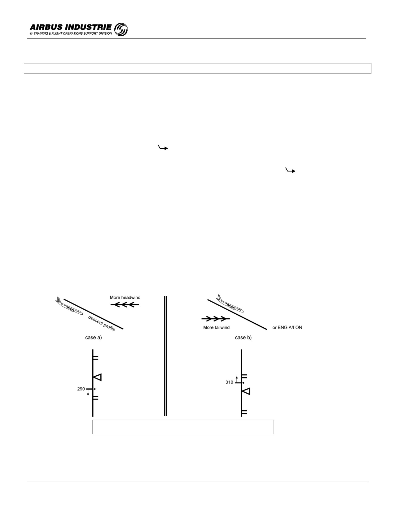
Managed Descent: Speed Target - Range Principle
DATE: JAN 2001
Page 35
UDY0102
A320 INSTRUCTOR SUPPORT
NORMAL OPERATION
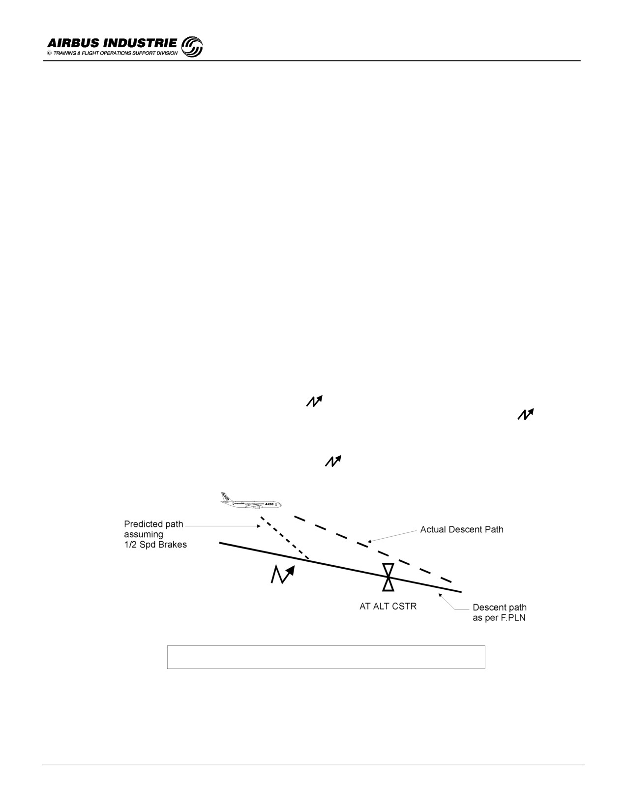
• Case a):
If the A/C tends to get below path, the current speed decreases towards the lower limit of the speed target range
to keep the A/C on path with IDLE thrust. If the speed reaches the lower limit, then SPEED mode engages on the
A/THR, to keep the A/C on path at that lower speed.
• Case b):
If the A/C tends to get high above path, the current speed increases towards the higher limit of the speed target
range to keep the A/C on path with IDLE thrust. If the speed reaches the higher limit, THR IDLE is obviously on the
ATHR; but the AP will not allow the speed to increase more than the higher limit to track the descent path. Thus
the VDEV will slowly increase.
-
If DES mode is engaged and the speed is selected, the descent profile is unchanged. Consequently DES
mode will do its best to keep the A/C on the descent profile but it will not allow the speed to deviate from its
target.
Let us suppose a descent profile computed assuming managed speed 300 kts. If the pilot selects 275 kts, the
A/C will most probably deviate above the descent profile and VDEV will increase.
In many cases, ATC interferes with the proper achievement of the descent, and causes the A/C to be high above path
or too low. If DES mode is used, it will do its best to recover the descent path and match the constraints:
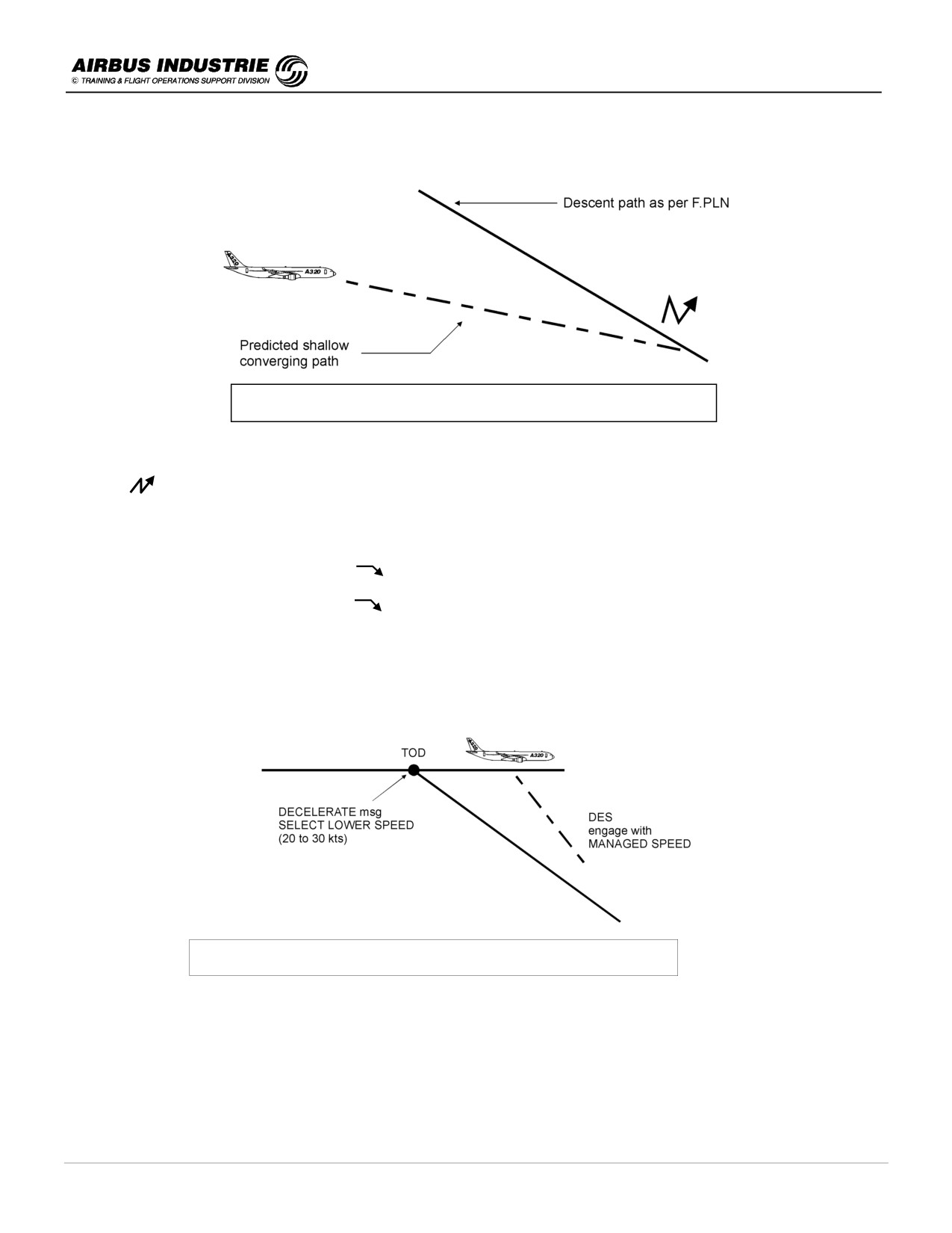
• Suppose the A/C is high above path and the pilot is cleared down. He presses DES mode with Managed Speed.
The AP will pitch the A/C down so as to fly the highest speed of the speed target range, with THR IDLE.
On the ND, an INTCPT point is displayed as a blue
symbol. It materializes where the A/C will intercept the
descent profile, assuming ½ SPD BRAKES extended. Thus if speed brakes are not extended, the
will slowly
move forward till it gets close to an altitude constrained waypoint. The EXTEND SPD BRAKE message then
comes up. This technique allows an altitude constraint to be matched with minimum use of speed brakes.
Therefore when HIGH ABOVE PATH, monitor VDEV and
to recover the descent path.
A/C above path - Path Intercept Prediction
DATE: JAN 2001
Page 36
UDY0102
A320 INSTRUCTOR SUPPORT
NORMAL OPERATION
• Suppose the A/C is below path and the pilot is cleared down. He presses DES mode with managed Speed.
A/C below path - Path Intercept Prediction
The DES mode will guide the A/C on a shallow descent converging towards the descent profile (1000 ft/mn or less
depending on the circumstances) with the ATHR on SPEED mode.
The
intercept point is then at a fixed position along the flight plan on the ND; it indicates the location where the
descent path will be intercepted.
These last 2 cases occur at each descent initiation where ATC requests:
-
either an early descent before TOD
; a shallow converging descent is commanded by DES mode (SPEED
- DES on FMA),
-
or a late descent beyond the TOD
; a steep converging descent is commanded by DES mode, the A/C
accelerating towards the top speed of the speed target range (THR IDLE - DES on FMA).
In that last case a message DECELERATE is provided on PFD once TOD is sequenced; this is an indication to
the pilot to select a lower speed (subject to ATC permission) in order to minimize the distance spent beyond TOD,
and to recover the descent profile more rapidly when DES mode is engaged and A/C accelerates to descent
speed with managed speed back ON.
A/C at CRZ altitude - Beyond TOD
Thus Managed DES mode makes the best use of A/C speed within the speed target range and of thrust (Idle or Speed
mode on A/THR) to track the descent profile. This is materialized on FMA by THR DES/DES, THR IDLE/DES,
SPEED/DES mode indications.
DATE: JAN 2001
Page 37
UDY0102
A320 INSTRUCTOR SUPPORT
NORMAL OPERATION
-
If, for any reason, the ATC requests a steeper descent while the A/C is in DES mode, on path or below, pull OPEN
DES mode, increase speed and use SPD BRK if necessary.
But don’t select higher speed, or extend speed brakes with managed DES, because in most cases this will result in
thrust increase, the aircraft being guided on the descent path by DES mode.
-
If HDG is pulled, DES mode reverts to V/S. In other words, selecting a Heading does not induce any change in A/C
pitch behaviour. It is then time for the pilot to increase/decrease the V/S target or select OPDES depending on
circumstances.
NOTE:
The pre-computed descent path is actually divided into successive descent segments. From TOD to the first
constrained waypoint it is an "idle segment", then geometric segments. The Idle segment assumes a given managed
speed flown with "Idle + ∆" thrust, this "∆" thrust above idle gives some flexibility for the FG to keep the A/C on the
descent path in case ENG A/I is used, or winds vary. This explains THR DES on FMA. The Idle factor set on A/C
STATUS page allows the ∆ to be adjusted: e.g. if - 2 is set, the Idle segment is steeper.
!
Selected OP DES or V/S
These selected modes are used during Radar Vectors or for pilot tactical interventions.
-
When OPEN DES is pulled the A/C will descend unrestrictedly down to FCU selected altitude, with THRUST
IDLE and speed target managed or selected. With managed speed, there is no longer a speed target range as
when managed DES is ON, since it no longer has any meaning and is useless in OP DES mode.
• If you wish to steep the descent down:
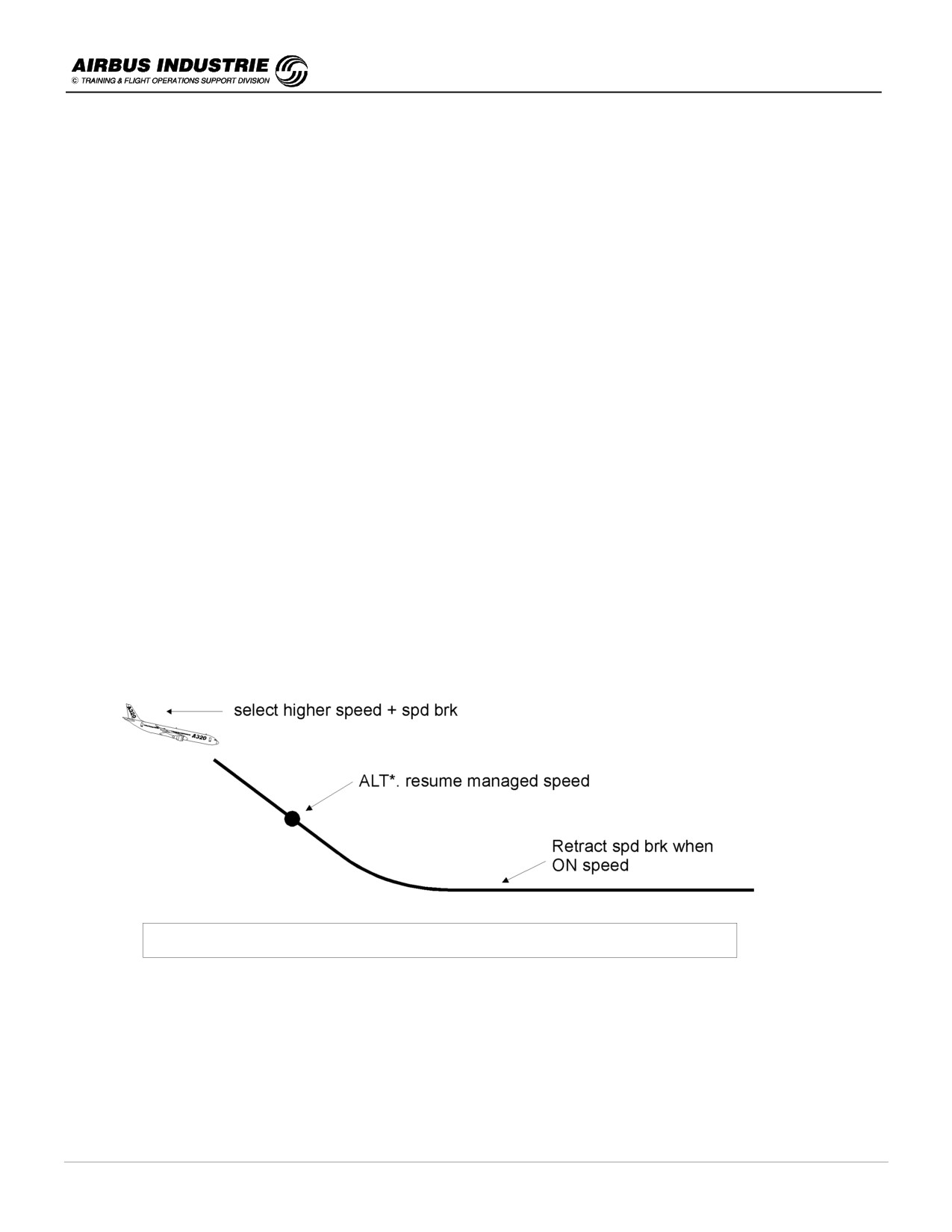
Select a higher target speed (subject to ATC permission); extend speed brakes if necessary, with OP DES
mode.
Resume the normal speed when reaching ALT* at the earliest or ALT, and retract speed brakes when
approaching target speed.
Speed management in descent for best altitude/speed trade off - OP DES mode
NOTE:
If you command a deceleration while the A/C is still in OP DES and too high, this brings the A/C still higher above
the intended path. Indeed, the A320 will get into a very shallow descent in order to decelerate.
• If you wish to shallow the descent, select a lower target speed or possibly V/S mode.
DATE: JAN 2001
Page 38
UDY0102

A320 INSTRUCTOR SUPPORT
NORMAL OPERATION
-
When V/S is used, the A/C is guided to that V/S with SPEED mode on ATHR.
In descent V/S is used:
• for small step descent, in order to get a smooth guidance with reduced thrust variations and
• when the A/C is significantly below path, a constant shallow V/S may be selected to smoothly recover (come
back) to the intended path.
If for any reason, V/S is selected with a high V/S target or typically after a DES ) V/S reversion, the A/P will pitch the
A/C down to fly the target V/S. Thus the A/C will tend to accelerate, while ATHR commands idle thrust to try to keep the
speed. When IAS reaches a speed close to VMO or VFE, the AP will pitch the A/C up so as to fly a V/S allowing VMO
or VFE to be maintained with idle thrust.
NOTE:
On the latest FG standard, when the target V/S as selected on FCU is no longer matched by the A/P to keep the A/C
within normal speed envelope, V/S is boxed amber on the FMA.
-
The monitoring cues used with OP DES and V/S are:
level symbols on the ND, related to FCU target altitude,
-
-
- Energy circle on the ND, when HDG or TRK modes are ON. This materializes the required distance to
descend, decelerate and land from present position
and the yoyo on the PFD, which may be used when the A/C is « not far » from the lateral F.PLN (small XTK). It
then gives a good assessment of whether the A/C is low or high related to the descent profile.
!
Holding patterns
If ATC requires the A/C to hold, insert the holding pattern in the F.PLN. The FMS computes the holding at green dot
speed taking into consideration the ICAO holding speed limits function of altitude (subject to holding table):
230 kts up to 14.000 ft,
240 kts up to 20.000 ft and
265 kts above.
If managed speed is used, the A/C will automatically decelerate to the holding speed at a point which is materialized
by the speed change symbol along the F.PLN, if NAV is ON.
Clean configuration is recommended for fuel considerations, and the LAT REV HOLD page indicates the latest
possible time to exit the hold in order to carry enough fuel for the remainder of the flight.
The holding pattern is not included in the descent path computation since the FMS does not know how many patterns
will be flown. Once the A/C enters the holding pattern, the yoyo indicates the instantaneous VDEV between the A/C
current altitude, and the altitude the A/C should fly at the exit fix of the holding pattern so as to be there on the descent
path; all other predictions assume one pattern.
DES mode guides the A/C down at V/S - 1000 ft/mn, while in the holding pattern.
DATE: JAN 2001
Page 39
UDY0102
A320 INSTRUCTOR SUPPORT
NORMAL OPERATION
!
Various Drills in descent
• Before TOD, select destination VOR/DME needle, press CSTR button on EFIS CTL panel, and set TCAS to
BELOW.
• As a general rule, preferably set PF MCDU on PROG, PNF MCDU on F PLN.
• Periodically crosscheck FM NAV ACCY. At TOD, entering TMA (typically 50 NM from destination), entering
Approach Zone (15 NM from destination) and whenever a NAV ACCY DNGRADED or an amber navigation
message comes up.
• At 10.000 ft, LDG Lights/Seat belts / ILS button if required.
• If RADAR is to be used, adjust the TILT up along with descent progress.
• If EGPWS is available, select TERRAIN ON ND on one side (it is exclusive of RADAR image) and Radar on
the other side.
• BARO REF - select QNH whenever cleared down to an ALTITUDE, at transition level at the latest.
• If ENG A/I is to be used and you notice that this brings the A/C high above path, extend ½ SPD BRAKE to
compensate.
• Whenever ATC orders a level off and A/C is high above path, SELECT a lower speed. When ATC clears you
to resume descent, OP DES pull and SELECT a higher speed.
• Don’t forget simple rules such as:
Remaining DIST (NM) to descent = ∆ ALT (ft ) / FPA (°).
Reach 9.000 ft/250 kt by approximately 30 NM from touch down.
→ Speed brake half extension ⇒ Descent gradient increases by 50 %.
→ Speed brake full extension ⇒ Descent gradient increases by 90 %.
Descent speed
Angle of descent
Half speed brakes
Full speed brakes
325 kt
5 °
7.5 °
9 °
300 kt
4 °
6 °
8 °
250 kt
3.3 °
5 °
7 °
210 kt
3 °
4.5 °
6 °
Emergency descent - MMO/VMO, Full speed brakes
10 °
EFFICIENT DESCENT MANAGEMENT = BEST SPEED VS ALT TRADE OFF
DATE: JAN 2001
Page 40
UDY0102

A320 INSTRUCTOR SUPPORT
NORMAL OPERATION
11 - APPROACHES
The approach briefing by instructors needs to be STRUCTURED so that pilots have a good guideline or SKELETON
applicable to any type of approach. All approaches shall then be flown similarly.
Therefore, the approach briefing notes are structured as follows:
1.
General Approach Briefing
2.
ILS Approach
-
Standard ILS,
-
High above G/S and
-
ILS with raw data.
3.
Non Precision Approach
4.
Circling Approach
5.
Visual Approach
Once the skeleton has been given in the first General approach briefing 11/1, it is then only a matter of cascading the
specific particulars for each approach type.
DATE: JAN 2001
Page 41
UDY0102
A320 INSTRUCTOR SUPPORT
NORMAL OPERATION
11/1 - GENERAL APPROACH BRIEFING
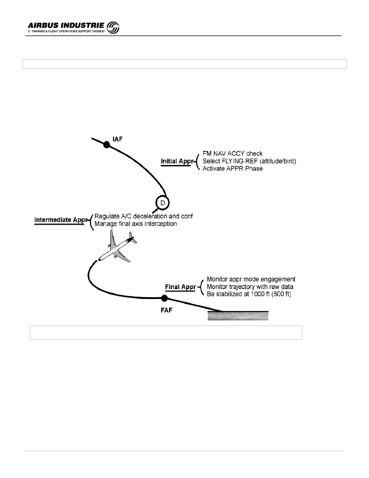
All approaches are divided into 3 parts:
-
the Initial Approach, from IAF (≅ 15 NM from destination) to the activation of approach phase materialized by the
(DECEL) pseudo waypoint,
-
the Intermediate Approach from (DECEL) to FAF and
-
the Final Approach from FAF to landing or minimum.
In each of these parts there are various drills which have to be achieved regardless of the approach type.
Drills to be achieved throughout the 3 phases of any approach
!
Initial approach
a) FM NAV ACCY check using raw data (not necessary if GPS primary).
The result of the NAV ACCY check determines the strategy on how to conduct the approach. Which display mode
will be used on ND and which guidance modes may be used with AP/FD.
E.g., if check is positive or GPS is Primary:
→ PF and PNF ND on ARC or ROSE NAV,
→ AP/FD Lateral/Vertical managed modes may be used and
→ EGPWS set ON.
DATE: JAN 2001
Page 42
UDY0102
A320 INSTRUCTOR SUPPORT
NORMAL OPERATION
b) Select the BEST FLYING REFERENCE for the approach.
-
The FPV (called BIRD) is best adapted for all types of approaches and is strongly recommended for NPA or
VISUAL approaches (BIRD ON).
-
Attitude associated to FD crossbars is still most commonly used to fly ILS approaches (BIRD OFF).
c) ACTIVATE THE APPR PHASE
The purpose of this activation is to initialize the deceleration towards VAPP or towards the speed constraint
inserted at FAF, whichever applies.
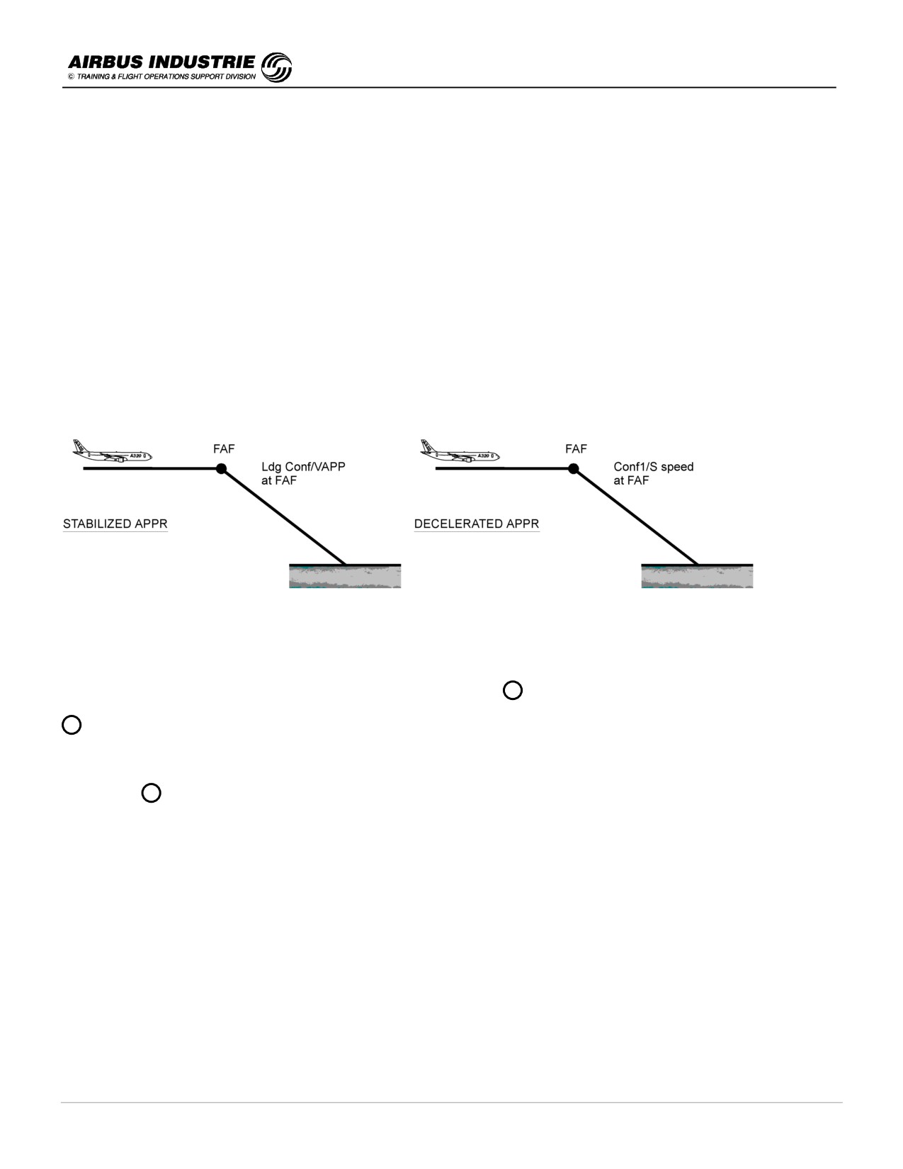
There are actually 2 approach techniques:
-
the stabilized approach technique for which the A/C reaches FAF in Landing CONF and VAPP; the Final
Approach is flown down with VAPP and
-
the decelerated approach technique for which the A/C reaches FAF in CONF1 and S speed. Then, when flying
below 2000 ft AGL, the pilot will continue the deceleration and configuration changes so as to be stabilized with
VAPP and Landing Configuration, at 1000 ft (IMC) or at 500 ft (VMC) at the latest.
-
Stabilized Approach Technique is generally used for NPAs.
-
Decelerated Approach Technique is normally used for ILS approaches.
The FMS provides a (DECEL) pseudo waypoint materialized by a D along the FPLN on the ND, indicating where to
start the deceleration towards approach speed VAPP.
D is computed assuming a decelerated approach technique. Hence, if you wish to fly an NPA or a stabilized
approach, insert VAPP as a SPEED CSTR at FAF, in order to get a valuable (DECEL) pseudo waypoint.
When NAV mode is engaged with managed speed, the Approach phase activates automatically when sequencing
(DECEL) or D .
When HDG mode is selected (e.g. for radar vectoring), you will have to manually activate the Approach phase on
appropriate PERF page.
Other drills:
-
ensure proper sequencing of the FPLN when radar vectored (monitor the TO waypoint on ND),
-
check adequate NAVAIDS are selected,
-
ensure the ILS P/B is properly set and
-
ensure proper setting of BARO REFERENCE.
DATE: JAN 2001
Page 43
UDY0102
A320 INSTRUCTOR SUPPORT
NORMAL OPERATION
!
Intermediate Approach
The purpose of the intermediate approach is to bring the aircraft at the proper speed, altitude and configuration at FAF,
and to guide the aircraft to the proper final trajectory at FAF.
a)
Aircraft deceleration and configuration changes
Managed speed is recommended.
Since the APPR Phase is activated, the target magenta Speed on PFD is VAPP; the ATHR which most probably
is in SPEED mode, will guide the aircraft towards the target speed, lower limited to maneuvering speed of current
configuration:
e.g.:
if CONF0, maneuvering speed is O (higher than VAPP) and
if CONF1, maneuvering speed is S (higher than VAPP).
Hence the deceleration will be achieved by successive changes of configuration:
-
for ILS approaches, when O + 10 kt is reached, select CONF1; the A/C will decelerate to S.
-
for NPA or stabilized approaches, when successive Maneuvering speeds + 10 kt are reached, select next
CONF (this prevents thrust increase by ATHR when reaching maneuvering speeds):
O + 10 kt
⇒ Select CONF1,
S + 10 kt
⇒ Select CONF2, then landing gear down and in sequence,
F + 10 kt
⇒ Select CONF3, then CONF FULL.
Hence if ATC requests to maintain a given speed down to a given position, select the Configuration for which the
maneuvering speed is the closest:
e.g. ATC requests: «maintain 180 kt till 8 NM inbound the runway», the Procedures is:
- select CONF1. If S is within 5 kt of the request, keep managed speed. Else, select 180 kt on the FCU.
- reaching 8 NM inbound, press the speed P/B on the FCU to resume managed speed and further deceleration.
You may fly BELOW the maneuvering speed of the current configuration, provided you fly ABOVE VLS.
b)
Interception of the Final Approach axis
Refer to applicable raw data (LOC, needles or XTK).
If ATC clears the interception of the Final approach trajectory along the FPLN route, use NAV mode if FM ACCY
CHECK is OK.
Once cleared for the Approach by ATC, press the APPR P/B to arm the approach modes when applicable.
Other drills:
• When selecting Next Configuration, check IAS is lower than VFE next CONF.
• If TWR gives a new wind for landing, update it on PERF APPR.
DATE: JAN 2001
Page 44
UDY0102
A320 INSTRUCTOR SUPPORT
NORMAL OPERATION
!
Final Approach
a)
Monitor the Final Approach mode engagement:
• G/S * or FINAL engagement when required, or select Final descent path FPA reaching FAF,
• if the capture or engagement is abnormal, take over manually by selecting the proper FPA.
b)
Monitor the Final Approach using raw data:
• LOC - G/S deviation symbols for ILS,
• VDEV - XTK and FPLN for managed APPR (GPS primary),
• VDEV - XTK + needles / DME / ALT for NPA (non GPS primary) and
• Needles / DME / ALT / Time for NPA when FM NAV ACCY check is negative.
c)
Managed speed is recommended to benefit from the GS MINI SPEED guidance. It assists the pilots in case of
longitudinal shears.
• Aircraft must be stabilized in Landing CONF at VAPP
by 1000 ft (IMC)
At the latest
by 500 ft (VMC)
• If there is a significant change in tower wind, PF shall ask PNF to modify it on PERF APPR, above 1000 ft
AGL.
• If the A/C has a tendency to be FAST and/or HIGH on final, EXTEND LANDING GEAR earlier, but below 220
kt preferably.
Don’t use SPD BRK on final, which have little efficiency at low speed, and auto retract when:
SPEED BRAKE AUTO RETRACT
CONF
A 319 and A 320
FULL
A 321
3 and FULL
NOTE:
If you select next CONF, with IAS > VFE NEXT CONF, with FPA mode engaged, the AP/FD will deviate from target
FPA and will shallow the descent in order to decelerate the A/C towards VFE.
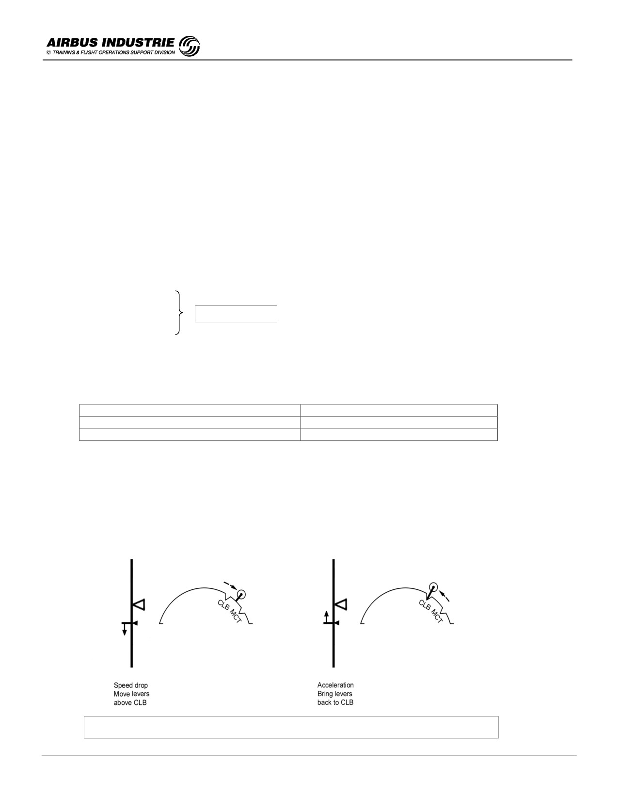
• Keep hands on the thrust levers while ATHR is ON in final, so as to be prepared to react when needed. If for
any reason the speed drops below VAPP significantly, push the levers forward above CLB detent (but below
MCT) till the speed trend arrow indicates an acceleration. ATHR is then armed with MAN THR white on FMA.
Then bring the thrust levers back into CLB detent. This is enough to be quickly back on speed.
Speed drop in approach - Recommended Recovery Technique
DATE: JAN 2001
Page 45
UDY0102
A320 INSTRUCTOR SUPPORT
NORMAL OPERATION
• A deceleration below VAPP may occur in following cases:
-
GPWS terrain avoidance maneuver,
-
Collision avoidance maneuver,
-
Windshear escape maneuver.
In all those cases, the pilot shall slam all thrust levers to TOGA.
NOTE:
Be aware that if you move thrust levers up to TOGA, SRS / GA TRK will engage.
• Go around altitude must be set on the FCU. This is done at Final approach descent initiation either when G/S
or FINAL modes engage or, if FPA mode is used when the A/C current altitude is below the Go Around altitude
(in order to avoid an undue ALT *).
• In case a major navigation problem occurs such as loss of raw data, FM NAV ACCY check negative or other,
interrupt the approach.
• Reaching MDA or DH, at MINIMUM auto call out:
-
if visual, continue and land if the A/C is properly established or
-
if no visual, Go Around.
This explains why MDA is not set as target altitude on the FCU. MDA is a decision altitude. Should the MDA be set
as FCU target, this would cause a spurious ALT* when getting close to MDA, bringing the A/C above final path and
destabilizing the approach at a critical moment.
DATE: JAN 2001
Page 46
UDY0102

A320 INSTRUCTOR SUPPORT
NORMAL OPERATION
11/2 - ILS APPROACH
A)
Standard ILS approach
Decelerated approach is recommended. The following particulars apply for ILS approaches:
!
Initial Approach
-
For CAT I ILS, insert D(A) value into MDA field
[or D(H) value into MDH field for QFE equipped a/c] on PERF
APPR page, since these are baro referenced.
-
For CAT II, III, ILS insert DH into DH field on PERF APPR page, since DH is a radio altitude.
-
Check that ILS P/B is illuminated on EFIS CTL panel, and that LOC G/S scales and deviations are displayed
on PFD.
-
Check ILS IDENT on PFD; if no or wrong ident displayed, check the audio ident.
-
Select Attitude flying reference on FCU, in other words BIRD OFF.
!
Intermediate Approach
-
If ATC clears for LOC capture only, press LOC P/B on the FCU
-
If ATC clears for the approach at a great distance (e.g. 30 NM)
* press APPR P/B,
* LOC/ G/S modes will arm/engage,
* be aware that G/S may be perturbed,
* CAT I will be displayed on FMA, till a valid R/A signal is received.
-
If G/S INTCPT altitude is AT or BELOW 2000 ft AGL, select CONF2 when reaching one dot below G/S.
!
Final Approach
-
Monitor with ILS deviations on PFD.
-
In case of a DOUBLE RECEIVER failure, interrupt the approach (RED LOC/GS flags - ILS scales removed -
AP trips off - FD goes to HDG - V/S).
-
In case of the ILS GROUND TRANSMITTER failure, AP/FD will remain ON with LOC/GS modes; this is
because such a failure is most commonly transient. In such a case, LOC/GS deviation indexes are lost, ILS
scales and FD bars flash. If R/A < 200 ft, Red LAND warning is triggered.
-
If the failure lasts more than several seconds, or in case of Red LAND warning, interrupt the approach.
-
Be aware that if for any reason you pull on V/S selector, while LOC/G/S track modes are engaged (ab. 400 ft),
HDG mode will automatically engage as well (with FM2, pulling V/S with LOC - G/S, does not modify the lateral
mode which remains LOC).
-
Hence if a heading was preset, the AP/FD will turn the A/C towards the preset heading.
-
Autoland may be attempted on CAT I ILS beam; however this requires proper visual references (at least CAT
I), proper monitoring and immediate take over if anything seems abnormal.
-
Furthermore this may be done only with the airline permission.
NOTE:
On A320, for ILS approaches with G/S higher than 3.5°, stabilized approach technique is recommended.
DATE: JAN 2001
Page 47
UDY0102
A320 INSTRUCTOR SUPPORT
NORMAL OPERATION
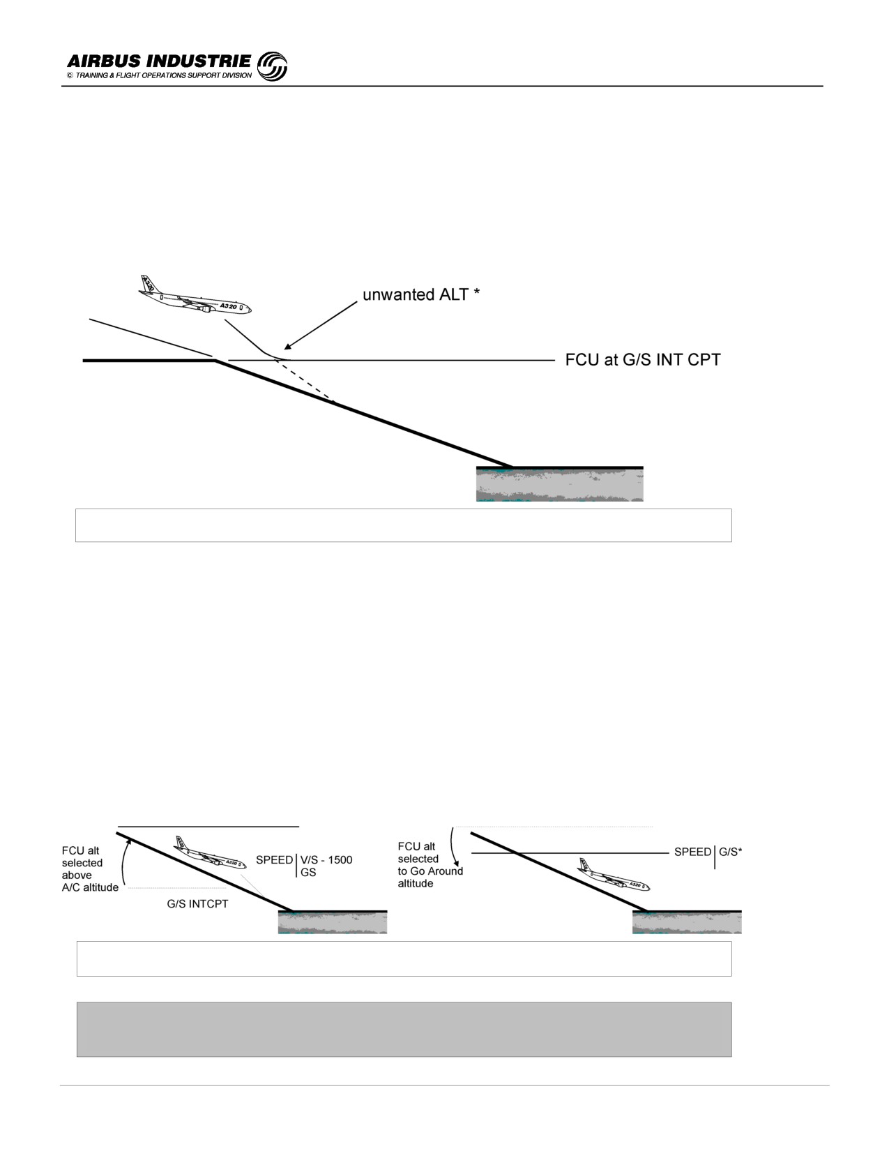
B) Glide Slope Interception from above
The problem is actually linked to the following factors:
-
High speed,
-
FCU altitude usually set at G/S INTCPT altitude and
-
G/S mode does not intercept from above.
A/C high above G/S - Potential AP / FD Problem
In such a case, the reaction of the crew must be rapid to succeed to stabilize the A/C at 1000 ft AGL, VAPP, LDG
CONF on G/S.
-
In order to get the best rate of descent, select LDG DN early (IAS < 220 kt) and successive flap configurations
reaching VFE next.
-
Then, typically, fly CONF2 - LDG GEAR DN - IAS = VFE2 - 5, in descent. This configuration gives you the best
flexibility to capture glide slope.
-
Select FCU altitude ABOVE A/C altitude in order to prevent undue ALT *.
-
Select V/S - 1500 ft (up to - 2000 ft/mn maximum).
-
When getting close to G/S, with G/S mode armed, G/S * will engage - Monitor the capture with raw data (pitch,
G/S deviation).
-
When G/S * engages, set FCU altitude to Go Around altitude.
-
Resume deceleration and flap configuration extension to reach VAPP, CONF FULL, and be stabilized on G/S by
1000 ft AGL.
A/C high above G/S - Recommended G/S Capture Technique
In case you feel you are too high or you won't make it,
do not hesitate to ask for a 360° turn for example.
DATE: JAN 2001
Page 48
UDY0102
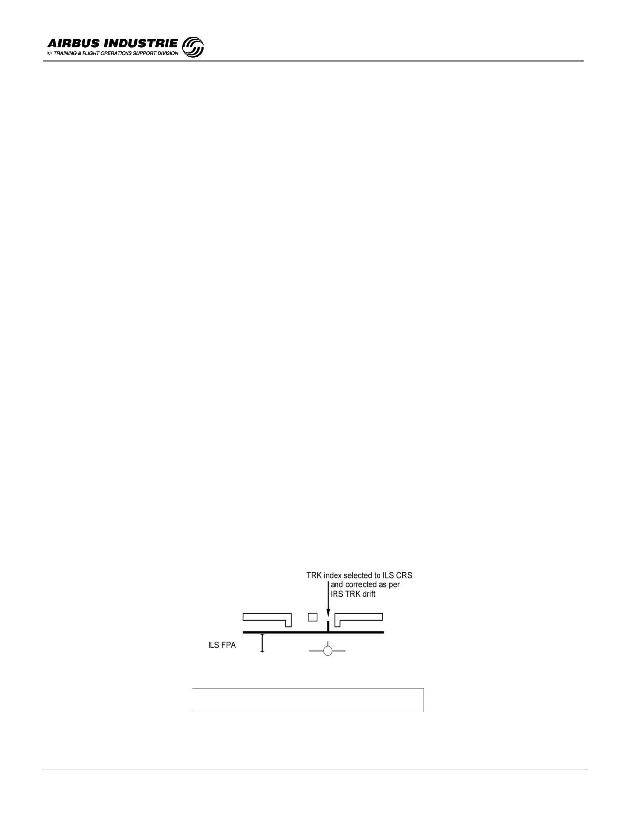
A320 INSTRUCTOR SUPPORT
NORMAL OPERATION
NOTE:
If, with high V/S, IAS increases to VFE, the AP/FD will no longer keep the target V/S. The AP/FD will pitch the A/C up
to shallow the descent so as to fly a speed lower than VFE. Do not extend Landing gear at too high speed (> 220 kts)
in order not to overstress the doors, and to minimize the noise.
C) ILS with raw data (CAT 1 only)
This is very seldom achieved in line; however in certain remote failure cases it may be necessary.
In most cases the BIRD is available such as in case of a total FCU failure.
The approach technique is a STABILIZED approach. The following particulars apply:
!
Initial Approach
-
Set BIRD ON as flying reference.
!
Intermediate Approach
-
Decelerate and reach FAF with CONF FULL - VAPP.
-
For LOC interception use any available data (LOC deviation index, needles, XTK or FPLN if available).
-
Set the ILS CRS as TRK selected target on the FCU once established on the localizer, so as to have it displayed
as reference track index on the PFD horizon line, and HDG - TRK scale.
-
For LOC tracking fly the BIRD to the TRK index on the horizon when LOC deviation is 0.
!
Final Approach
-
When ½ dot below G/S, initiate a smooth capture of the G/S by flying the BIRD down to the G/S flight path angle.
-
Monitor the raw data
• if LOC index deviates, fly the Bird into the direction of the LOC index relative to the TRK index on the horizon
line,
• once back on LOC, fly the BIRD back to the TRK index,
• if LOC deviates again, this means that there is a slight drift in the IRS TRK, which affects the BIRD; correct the
selected TRK as per the determined IRS track drift and
• if G/S index deviates, make small corrections (1°) in the direction of the deviation.
NOTE:
The BIRD is computed out of IRS data. Thus it may be affected by IRS data drift amongst others (TRK). A typical TRK
error at the end of a flight is 1° to 2°.
ILS with raw data - Use of FPV
DATE: JAN 2001
Page 49
UDY0102
A320 INSTRUCTOR SUPPORT
NORMAL OPERATION
The BIRD is NOT best adapted to fly GO AROUND. Indeed, the go around is a pitch dynamic maneuver, during
which the bird is lagging behind due to the inertia of the aircraft.
Hence if GO AROUND is initiated while BIRD is ON, it is then recommended to ask the PNF to set BIRD OFF, in order
to fly with the attitude reference and FD bars.
NOTE:
With the latest FCU (and proper pin program), at go around initiation - FDs are automatically turned ON - flying
reference reverts to attitude (HDG - V/S). Bird disappears and crossbars are displayed.
DATE: JAN 2001
Page 50
UDY0102

A320 INSTRUCTOR SUPPORT
NORMAL OPERATION
11/3 - NON PRECISION APPROACHES (NPA)
The stabilized approach technique is recommended. Reach FAF with CONF FULL and VAPP.
The following particulars do apply to NPAs.
The overall strategy of NPA completion is to fly it « ILS alike » with the same mental image or representation, and
similar procedure. Instead of being referred to an ILS beam, the AP/FD guidance modes and associated monitoring
data are referred to the FMS F.PLN consolidated by raw data, with the exception of LOC only approaches, where LOC
mode and localizer scale are to be used. This explains why the crew must ensure that the FMS data is correct; FMS
accuracy, FPLN data (lateral and vertical), proper leg sequencing.
!
Initial Approach
-
NAV ACCY CROSS CHECK is most essential since it determines:
which AP/FD guidance mode may be used,
which ND DISPLAY mode may be used and
which raw data must be used.
If GPS is PRIMARY or NAV CROSS CHECK is POSITIVE. Managed and selected AP/FD modes may be used, as
well as ND ROSE NAV / ARC modes.
If NAV ACCY CHECK is NEGATIVE. Selected AP/FD modes may only be used, and monitoring is achieved with
raw data only.
If GPS is PRIMARY at the beginning of initial approach, it will most probably remain primary throughout the
approach. However if for any reason GPS PRIMARY is LOST then:
• a GPS defined approach cannot be flown as if ILS signal was lost for ILS approach and
• a VOR (NDB …) approach may be continued, as if without GPS. The strategy is merely a function of NAV
ACCY CHECK.
-
Set the BIRD ON as flying reference.
-
Set VAPP as SPD CSTR at FAF, in order to get a meaningful (DECEL) pseudo waypoint.
Other drills:
-
ILS P/B set to OFF in order to get VDEV BRICK on PFD (except for LOC only approaches, where ILS P/B is set
ON and the yoyo is used as VDEV),
-
NAVAIDS - ensure that approach reference navaid is inserted and display associated needles.
DATE: JAN 2001
Page 51
UDY0102
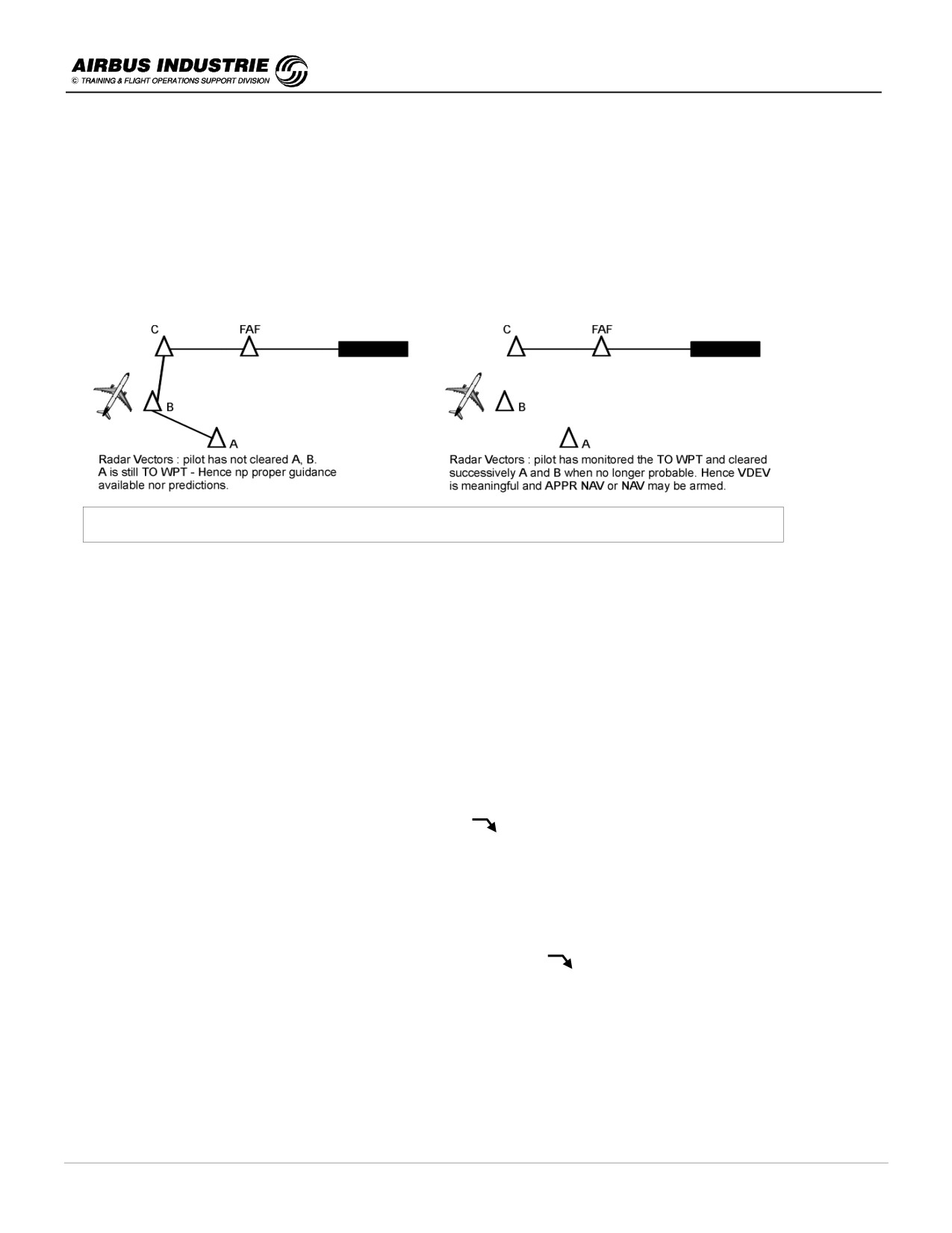
A320 INSTRUCTOR SUPPORT
NORMAL OPERATION
!
Intermediate Approach
It is very important to have a correct FPLN in order to ensure a proper Final Approach guidance. Indeed the NAV and
APPR NAV modes are always guiding the A/C along the ACTIVE LEG of the FPLN, and the managed VERTICAL
mode ensures VDEV = 0, VDEV being computed along the remaining FPLN to destination.
Hence monitor the proper sequencing of the FPLN, more specifically if HDG is selected. Check on ND top right hand
corner that the TO WPT is the most probable one, or meaningful.
Radar vectors - Properly Monitor FPLN Sequencing
-
When cleared for the approach:
if managed approach ⇒
press APPR P/B (this brings VDEV brick up if not yet there),
if selected approach
⇒
select adequate TRK on FCU to carry out the interception.
Other drills:
-
The monitoring of the interception must be achieved using the applicable raw data depending upon the result of the
NAV ACCY CHECK or whether GPS is PRIMARY.
!
Final Approach
The final Approach will be flown either MANAGED or SELECTED.
-
If MANAGED Approach
• Monitor the engagement of FINAL APP mode; use
start of descent blue symbol on ND, VDEV and FMA on
PFD.
• Use ATHR and Managed speed.
• With GPS PRIMARY, monitor VDEV / XTK / F.PLN on ND.
• For VOR - ADF
… approaches, monitor VDEV / XTK / F.PLN confirmed by needles on ND, and DME versus
altitude if available.
• Set Go Around Altitude.
If for any reason, FINAL APPR does not engage at start of descent
, rapidly select FPA convergent to the Final
Descent Path so as to fly with VDEV 0. Once VDEV = 0, you may try to re-engage APPR.
DATE: JAN 2001
Page 52
UDY0102
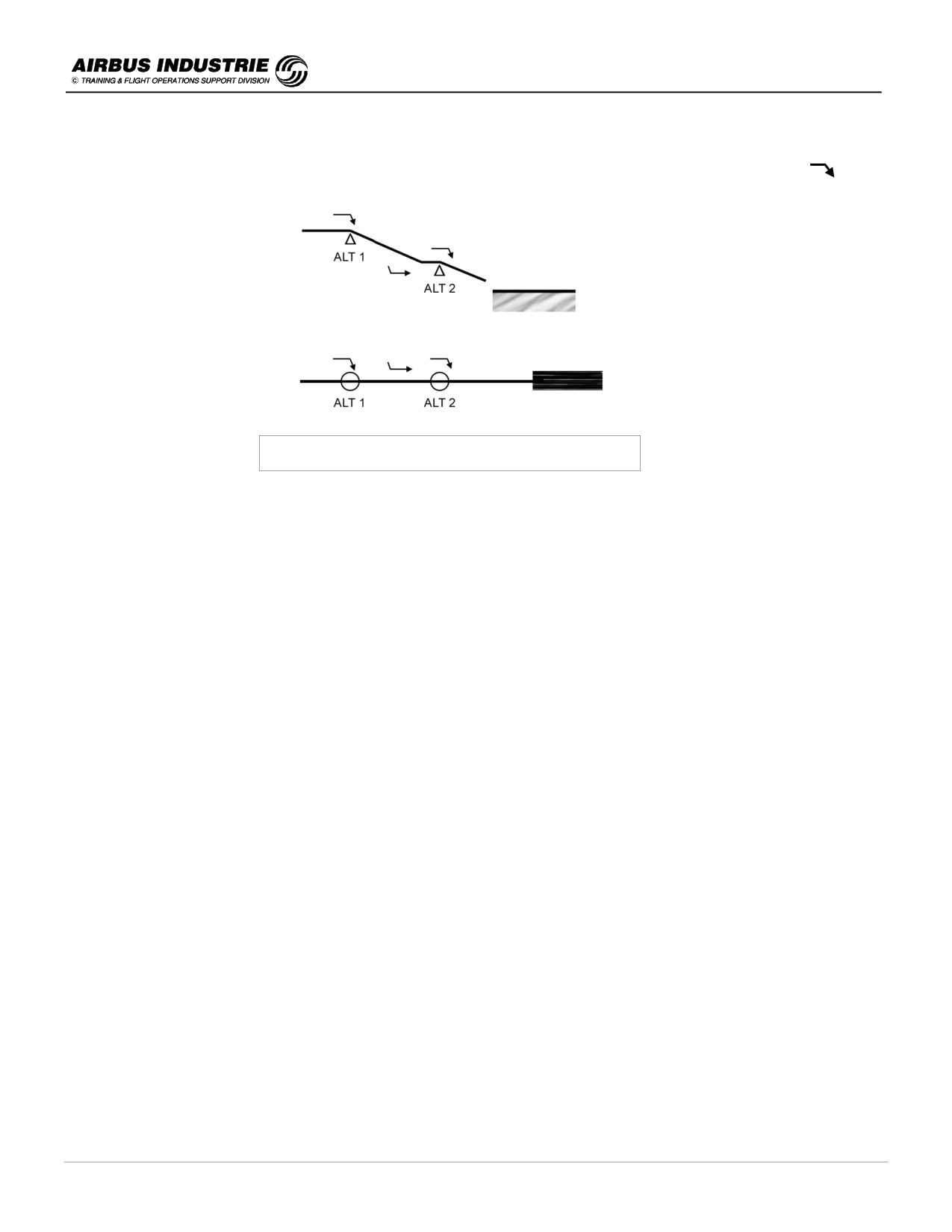
A320 INSTRUCTOR SUPPORT
NORMAL OPERATION
In certain cases, the FINAL APPR flies an « IDLE DESCENT Segment » from one ALT CSTR to another, followed by a
level segment. This is materialized by a magenta level off symbol on ND followed by a blue start of descent
Final approach trajectory - an idle descent segment
If during the final approach the message NAV ACCY DNGRADED comes up, immediately refer to raw data:
-
If the check is OK, you may continue.
-
If the check is NEGATIVE, select TRK - FPA and refer to raw data.
If during the final approach, the message GPS PRIMARY LOST comes up while the A/C flies a GPS approach,
INTERRUPT the approach.
Reaching MDA, at MINIMUM call out:
-
if visual and properly established, continue and land with AP OFF and both FDs OFF or
-
if no visual, Go Around.
NOTE:
Non precision approaches (NPA) must be properly coded in the Nav Data Base so as to be satisfactorily flown with
the APPR NAV/FINAL managed modes. This coding, more specifically the vertical part of it, is verified by the airlines.
Should there be any doubt on the vertical F.PLN, the crew may then elect to fly the approach with NAV/FPA modes,
provided the NAV ACCY CHECK is OK.
NOTE:
If you fly an NPA with managed modes, do not modify the Final Approach F.PLN data (clear waypoints or
modify altitude constraints); do not insert DIR TO an intermediate waypoint of the final approach segment.
DATE: JAN 2001
Page 53
UDY0102
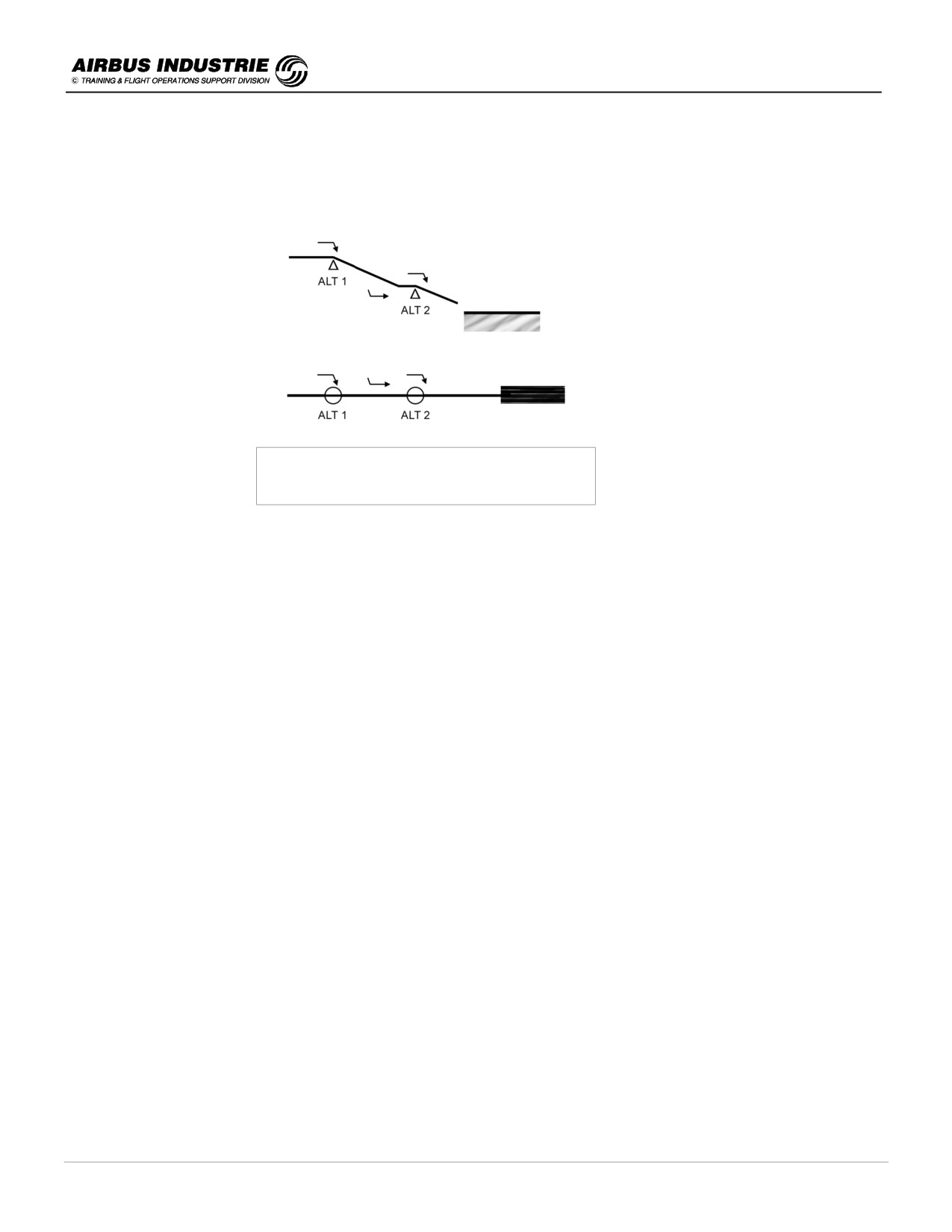
A320 INSTRUCTOR SUPPORT
NORMAL OPERATION
-
If SELECTED Approach
• Overfly FAF, properly identified, and
• select TRK = Final APPR CRS,
• select FPA = Final APPR path (actually start the final descent 0.3 NM before FAF).
Final approach using the bird with AP/FD -
TRK/FPA modes
-
Use ATHR and Managed speed.
-
If GPS PRIMARY, monitor VDEV/XTK/F.PLN on ND. For VOR, ADF approaches, monitor Raw data.
-
Set Go Around altitude ONCE the A/C altitude is below that altitude.
Reaching MDA
-
If visual and properly established, continue & land with AP OFF and both FDs OFF.
-
If not visual, Go Around.
NOTE:
If at MDA, distance to runway is not properly assessed, you may level off at MDA till MAP, at the latest. Then Go
Around.
-
If LOC ONLY approach
As for all Non Precision Approaches, the recommended flying reference is the Bird; the recommended FG modes for
the final approach are LOC/FPA with managed speed on ATHR.
In initial approach select the ILS P/B ON, on the EFIS CTL panel.
In intermediate approach, press LOC P/B on the FCU to arm LOC mode and monitor LOC*.
In final approach, coming to FAF, select FPA = Final approach path and monitor the final approach with LOC deviation
index, DME/ALT or time, yoyo …
-
If LOC BACK COURSE approach
The recommended flying reference is the BIRD and the FG recommended modes for final approach are TRACK-FPA
with managed speed on ATHR.
Before or during initial approach: select the ILS with its front course on RAD NAV page. Do not select the ILS or LS
P/B on EIS Control Panel since the localizer deviations on the PFD will be provided in opposite direction.
On the PF side, select ROSE ILS on EIS Control Panel to get the proper localizer deviations (this is why the ILS front
course in inserted on RAD NAV).
DATE: JAN 2001
Page 54
UDY0102
A320 INSTRUCTOR SUPPORT
NORMAL OPERATION
During intermediate approach: use TRK mode to align the aircraft on the localizer. The PNF ND on ARC mode provide
valuable information to achieve that goal, provided FMS ACCY is OK or GPS is Primary.
In Final approach: use FPA mode to set the aircraft on the final descent path. The PNF ND should then be set to
ROSE ILS.
DATE: JAN 2001
Page 55
UDY0102
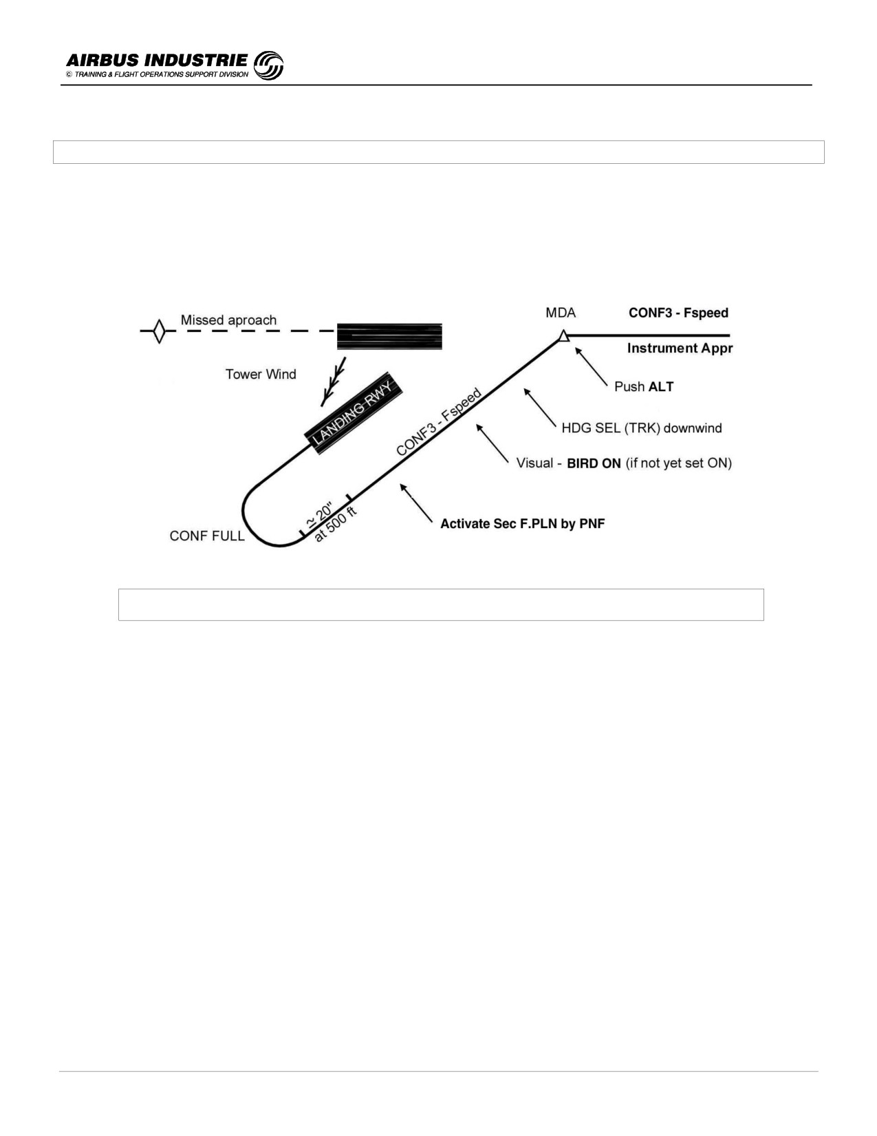
A320 INSTRUCTOR SUPPORT
NORMAL OPERATION
11/4 - CIRCLING APPROACH
The circling approach is flown when the tower wind is such that the landing runway is different from the runway fitted
with an instrument approach, which is used to descend and approach in order to get visual of the airfield.
The instrument approach prior the circling is a stabilized approach flown in CONF3 - L/G Down - F speed, with
BIRD ON or OFF, depending upon the approach type. BIRD will be selected ON at the beginning of circling if not
before, and circling pattern is flown visual with FDs OFF.
Typical Circling Approach - Lateral Profile
-
Descent and Approach Preparation
F Flight Plan Revisions
• Lateral F.PLN - the approach is the Instrument Approach to destination.
• Vertical F.PLN - insert F speed constraint at FAF, since instrument approach will be flown CONF3 - L/G DN -
F Speed.
This allows you to have a proper descent profile, proper prediction, VDEV, etc. and a comprehensive ND.
P Perf Data
• PERF APPR - insert Tower wind as usual.
R Rad Nav
• The insertion of the instrument approach ensures proper autotune; else manually tune the desired Navaid.
S Sec F.PLN
• Copy Active F.PLN. Revise the Approach by selecting the Landing Runway (keep the F.PLN discontinuity).
Thus while in the visual pattern, after having activated the SEC F.PLN, it will be most comfortable to have a
proper ND display, materializing the landing axis and runway.
DATE: JAN 2001
Page 56
UDY0102
A320 INSTRUCTOR SUPPORT
NORMAL OPERATION
-
Final instrument approach
Fly it with CONF3 - L/G GEAR DN - F speed, with the usual technique.
Reaching MDA - push TO LEVEL OFF.
• If visual, proceed down wind (HDG SEL or TRK SEL).
• If no visual, fly till MAP. If no visual till MAP, Go Around.
-
Circling approach
• Once visual, proceed downwind, initially with HDG or TRK mode in order to join downwind.
• Set BIRD ON, keep ATHR ON, and set both FDs to OFF.
• Activate SEC FPLN. This ensures a comprehensive ND and a proper GS MINI managed speed target when
on final approach to landing runway.
• Circling approach must be flown VISUAL. In case of loss of visual contact with ground, proceed for GO
AROUND and MISSED APPROACH as defined for the instrument approach. The missed approach must
be flown with raw data, since it is no longer part of the F.PLN. Thus the crew has to anticipate how to join the
published missed approach, turn direction, configuration in the turn, initial climbout altitude. If a sharp turn is
expected, keep FLAP3 (or FLAP2) and low speed; in other words, delay flap retraction until properly on
trajectory, if required.
NOTE:
If landing is achieved on opposite runway to the instrument approach, when leveling at MDA with visual references
acquired, turn (L or R) 45° during 30 sec to join downwind.
The recommended configuration for the instrument approach part of the procedure is CONF3 - LDG DN with all engine
operative or one engine inoperative. The reason for landing gear being selected down so early is not to trigger the
landing gear not down red warning, and to have to disregard it.
DATE: JAN 2001
Page 57
UDY0102
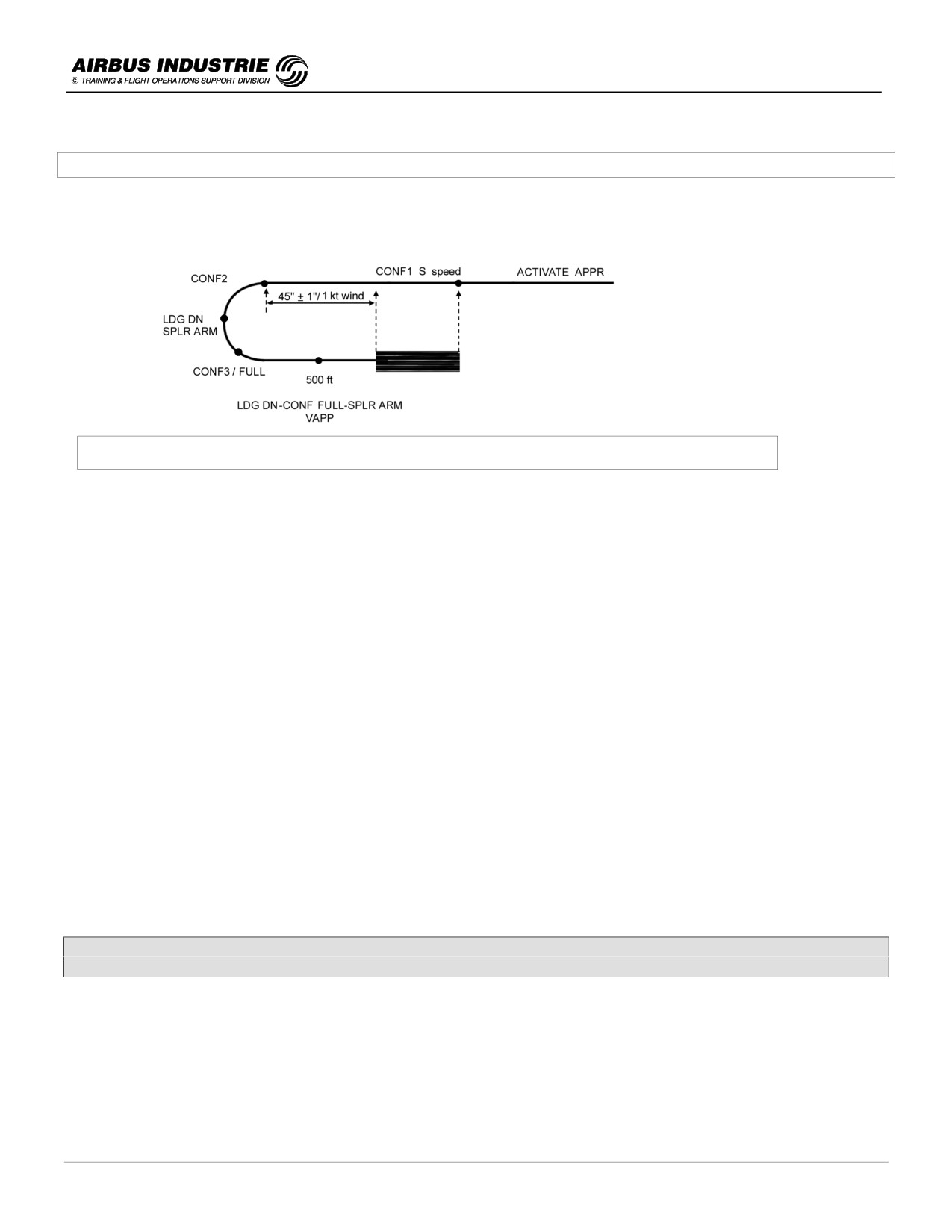
A320 INSTRUCTOR SUPPORT
NORMAL OPERATION
11/5 - VISUAL APPROACH
The visual approach is flown with (FPV) BIRD ON, AP/FDs off, ATHR ON and managed speed.
Typical Visual Pattern - Lateral Profile
!
Initial Approach
As a help to have a comprehensive display on ND, ND may be set to ROSE NAV to assist the pilot to visualize the
circuit from mid-downwind.
At the beginning of downwind leg, activate the APPR PHASE. The FCU altitude target is selected as downwind leg
altitude, and the FCU track target to downwind leg course.
!
Intermediate / Final approach
- Downwind CONF1 - S speed.
- Ask PNF to set downwind leg TRK (index on horizon line as an assistance).
- Assess A/C position visually (XTK is an assistance).
- End of downwind - CONF2 start base turn.
- During base usually shallow descent - ask LDG DN / SPLR arm.
- Ask PNF for RWY TRK and GO AROUND ALT on FCU.
- Then FLAP3 / FLAP FULL.
- At 500 ft, the A/C must be stabilized (L/G DN - FLAP FULL - VAPP).
!
Other drills
- In case of turbulence / misalignment … be SMOOTH on the side stick. The A/C is « naturally » very stable.
- Once established on the descent path, DON’T DUCK UNDER in short final.
AN AIRCRAFT PROPERLY STABILIZED ON SHORT FINAL
WILL HAVE A SAFE LANDING.
DATE: JAN 2001
Page 58
UDY0102
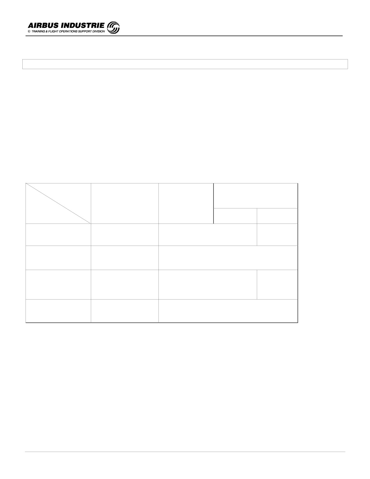
A320 INSTRUCTOR SUPPORT
NORMAL OPERATION
12 - PRECISION APPROACHES - CAT II - CAT III
!
General Consideration
• The only Precision Approaches are CAT I, II and III approaches. Since those approaches are flown to very low
DHs, with very low RVRs, the guidance of the aircraft on the ILS beam, and the guidance of the aircraft speed
must be CONSISTENTLY of HIGH PERFORMANCE and ACCURATE so that the transition to visual
conditions (if any) is achieved with the aircraft properly stabilized. Hence:
-
The Autoland is the preferred landing technique in such conditions.
-
Any failure of the automated systems shall not significantly affect the aircraft attitude and trajectory.
-
The aircrew task sharing and procedures allow you to rapidly detect any anomaly and thus lead to the
right decision.
• The general strategy for Precision Approaches is similar to the one applied for a standard ILS (or CAT I)
approach.
The main differences are outlined hereunder:
ILS
CAT III
Category
CAT I
CAT II
Strategy
DH
NO DH
Hand flown
AP/FD/ATHR
Flying Technique
AP / FD / ATHR down to DH
or AP/FD, ATHR
and Autoland
DA (DH) Baro ref
DH Radioaltimeter
Minima & Weather*
Ceiling + visibility
RVR
Possible with
Autoland
Autoland
precautions
Available & Recommended
must be used
Normal DA applies
Handflown in
Overweight Landing
exceptional
Autoland possible exceptionally - precautions
circumstances
* for CAT II/CAT III approaches, the weather at ALTN must be at least equal or better than CAT I.
DATE: JAN 2001
Page 59
UDY0102

A320 INSTRUCTOR SUPPORT
NORMAL OPERATION
• In order to fly a precision approach:
- the aircraft equipment and systems required must be available (FCOM 4.05.70),
- the airport equipment and installation required must be available and serviceable,
- the airport has to be operating in CAT II/III conditions,
- the aircrew must be qualified,
- the specific wind limitations (30 kts head, 10 kts tail, 20 kts cross), and the maximum altitude limit as per
AFM must be applied:
319
All
9200 ft
Basic
2500 ft
320
CFM mod 24617
9200 ft
IAE mod 23893
6500 ft
321
Basic
2500 ft
CFM 24385 or IAE 24386
5750 ft
-
G/S must be comprised between 2.5° and 3.15°.
NOTE:
If CATII/III training is being achieved on a given airfield, the airport must be advised. CAT II/III training may be
done on CAT I installation with precautions.
• The landing capability of the airborne systems is announced on the FMA:
-
CAT3 SINGLE is announced when the airborne systems are fail passive which means that a single
failure will lead to the disconnection of the AP without any significant consequent deviation from the flight
path and from present attitude, the aircraft remaining in trim.
Manual flight is then required. This explains why DH is 50ft.
-
CAT3 DUAL is announced when the airborne systems are fail operational. In case of a single failure, the
AP will continue to guide the aircraft on the flight path. Should the failure occur below the alert height the
Autoland maneuver will be achieved safely; in that case no capability degradation is indicated.
Such a redundancy allows NO DH or a DH 20ft.
-
However the indication CAT3 DUAL (SINGLE), which ensures that the level of redundancy of the
essential automated systems and of the required information is achieved, does not mean that the overall
A/C status allows for such low minima. Indeed some A/C systems are not monitored within this indication
(e.g. wipers, STD BY ATT indicator …).
NOTE:
Alert Height 200 ft. The Alert Height is defined for CAT III operations with a fail-operational system. It is linked to
the probability of failure of the automatic landing system. If a failure affecting the fail operational criteria occurs
below Alert height, no category degradation is indicated to the crew. An operator may choose an Alert Height
LOWER than the one mentioned in the AFM but not higher.
DATE: JAN 2001
Page 60
UDY0102