Airbus A320. AIRCRAFT CHARACTERISTICS AIRPORT AND MAINTENANCE PLANNING (2016-2023) - page 16
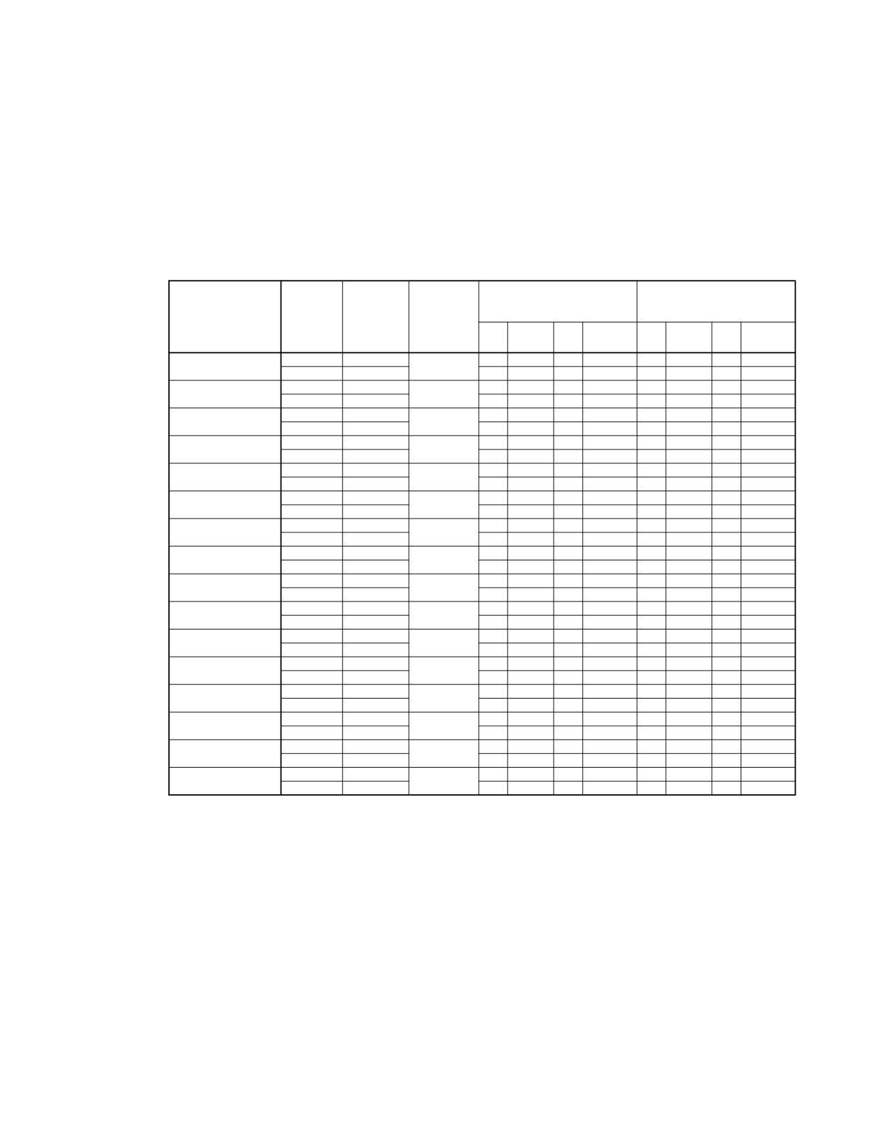
@A320
AIRCRAFT CHARACTERISTICS - AIRPORT AND MAINTENANCE PLANNING
**ON A/C A320-200
ACN FOR
ACN FOR
LOAD ON
RIGID PAVEMENT
FLEXIBLE PAVEMENT
TIRE
WEIGHT
ALL UP
ONE MAIN
SUBGRADES − MN/m?
SUBGRADES − CBR
PRESSURE
VARIANT
MASS (kg)
GEAR LEG
(MPa)
(%)
High
Medium
Low
Ultra−lowHigh
Medium
Low
Ultra−low
150
80
40
20
15
10
6
3
A320−200
77 400
46.6
44
46
49
51
40
41
46
52
1.20
WV007 (CG 37.5%)
42 000
46.5
21
23
24
25
20
20
22
25
A320−200
77 400
46.6
44
47
49
52
40
41
46
52
1.23
WV007 (CG 37.5%)
42 000
46.5
21
23
24
25
20
20
22
25
A320−200
77 400
46.6
42
45
48
50
39
41
46
52
1.07
WV007 (CG 37.5%)
42 000
46.5
20
22
23
25
19
20
22
25
A320−200
77 400
45.8
45
48
50
52
40
41
46
52
1.44
WV007 (CG 33%)
42 000
45.7
22
23
25
26
20
20
21
25
A320−200
77 400
45.8
43
45
48
50
39
40
45
51
1.20
WV007 (CG 33%)
42 000
45.7
21
22
24
25
19
20
21
25
A320−200
77 400
45.8
43
46
48
51
39
40
45
51
1.23
WV007 (CG 33%)
42 000
45.7
21
22
24
25
20
20
21
25
A320−200
77 400
45.8
41
44
47
49
39
40
45
51
1.07
WV007 (CG 33%)
42 000
45.7
20
21
23
24
19
19
21
25
A320−200
73 900
47.0
44
46
48
50
39
40
44
50
1.38
WV008
42 000
46.9
22
24
25
26
20
20
22
26
A320−200
73 900
47.0
41
44
46
49
38
39
44
50
1.14
WV008
42 000
46.9
21
23
24
25
20
20
22
25
A320−200
73 900
47.0
41
44
47
49
38
39
44
50
1.18
WV008
42 000
46.9
21
23
24
26
20
20
22
25
A320−200
73 900
47.0
40
43
45
48
37
39
44
50
1.03
WV008
42 000
46.9
20
22
23
25
19
20
22
25
A320−200
75 900
46.8
45
47
50
52
40
41
46
52
1.38
WV009
42 000
46.7
22
24
25
26
20
20
22
25
A320−200
75 900
46.8
42
45
48
50
39
40
45
51
1.14
WV009
42 000
46.7
21
22
24
25
20
20
22
25
A320−200
75 900
46.8
43
45
48
50
39
40
45
51
1.18
WV009
42 000
46.7
21
23
24
25
20
20
22
25
A320−200
75 900
46.8
41
44
47
49
38
40
45
51
1.03
WV009
42 000
46.7
20
22
23
25
19
20
22
25
A320−200
77 400
46.6
46
49
51
53
41
42
47
53
1.44
WV010 (CG 37.5%)
42 000
46.5
22
24
25
26
20
20
22
25
N_AC_070900_1_0120103_01_02
Aircraft Classification Number
ACN Table (Sheet 3 of 7)
FIGURE-7-9-0-991-012-A01
Page 5
Dec 01/20
7-9-0
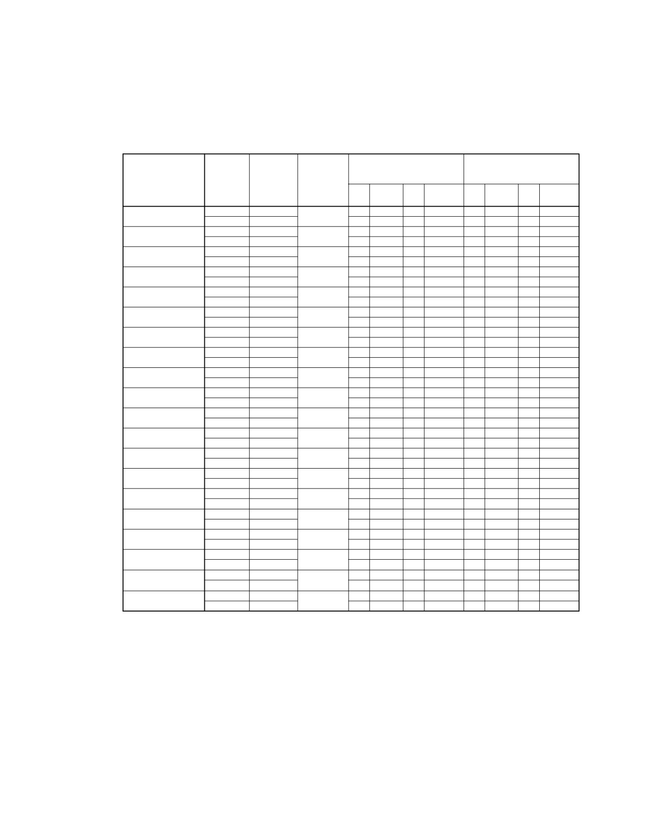
@A320
AIRCRAFT CHARACTERISTICS - AIRPORT AND MAINTENANCE PLANNING
**ON A/C A320-200
ACN FOR
ACN FOR
LOAD ON
RIGID PAVEMENT
FLEXIBLE PAVEMENT
TIRE
WEIGHT
ALL UP
ONE MAIN
SUBGRADES − MN/m?
SUBGRADES − CBR
PRESSURE
VARIANT
MASS (kg)
GEAR LEG
(MPa)
(%)
High
Medium
Low
Ultra−lowHigh
Medium
Low
Ultra−low
150
80
40
20
15
10
6
3
A320−200
77 400
46.6
44
46
49
51
40
41
46
52
1.20
WV010 (CG 37.5%)
42 000
46.5
21
23
24
25
20
20
22
25
A320−200
77 400
46.6
44
47
49
52
40
41
46
52
1.23
WV010 (CG 37.5%)
42 000
46.5
21
23
24
25
20
20
22
25
A320−200
77 400
46.6
42
45
48
50
39
41
46
52
1.07
WV010 (CG 37.5%)
42 000
46.5
20
22
23
25
19
20
22
25
A320−200
77 400
45.8
45
48
50
52
40
41
46
52
1.44
WV010 (CG 33%)
42 000
45.7
22
23
25
26
20
20
21
25
A320−200
77 400
45.8
43
45
48
50
39
40
45
51
1.20
WV010 (CG 33%)
42 000
45.7
21
22
24
25
19
20
21
25
A320−200
77 400
45.8
43
46
48
51
39
40
45
51
1.23
WV010 (CG 33%)
42 000
45.7
21
22
24
25
20
20
21
25
A320−200
77 400
45.8
41
44
47
49
39
40
45
51
1.07
WV010 (CG 33%)
42 000
45.7
20
21
23
24
19
19
21
25
A320−200
75 900
46.8
45
47
50
52
40
41
46
52
1.38
WV011 (CG 38.7%)
42 000
46.7
22
24
25
26
20
20
22
25
A320−200
75 900
46.8
42
45
48
50
39
40
45
51
1.14
WV011 (CG 38.7%)
42 000
46.7
21
22
24
25
20
20
22
25
A320−200
75 900
46.8
43
45
48
50
39
40
45
51
1.18
WV011 (CG 38.7%)
42 000
46.7
21
23
24
25
20
20
22
25
A320−200
75 900
46.8
41
44
47
49
38
40
45
51
1.03
WV011 (CG 38.7%)
42 000
46.7
20
22
23
25
19
20
22
25
A320−200
75 900
46.7
45
47
50
52
40
41
46
52
1.38
WV011 (CG 38.5%)
42 000
46.7
22
24
25
26
20
20
22
25
A320−200
75 900
46.7
42
45
48
50
39
40
45
51
1.14
WV011 (CG 38.5%)
42 000
46.7
21
22
24
25
20
20
22
25
A320−200
75 900
46.7
42
45
48
50
39
40
45
51
1.18
WV011 (CG 38.5%)
42 000
46.7
21
23
24
25
20
20
22
25
A320−200
75 900
46.7
41
44
47
49
38
40
45
51
1.03
WV011 (CG 38.5%)
42 000
46.7
20
22
23
25
19
20
22
25
A320−200
77 400
46.6
46
49
51
53
41
42
47
53
1.44
WV012
42 000
46.5
22
24
25
26
20
20
22
25
A320−200
77 400
46.6
44
46
49
51
40
41
46
52
1.20
WV012
42 000
46.5
21
23
24
25
20
20
22
25
A320−200
77 400
46.6
44
47
49
52
40
41
46
52
1.23
WV012
42 000
46.5
21
23
24
25
20
20
22
25
A320−200
77 400
46.6
42
45
48
50
39
41
46
52
1.07
WV012
42 000
46.5
20
22
23
25
19
20
22
25
A320−200
71 900
47.2
42
45
47
49
38
39
43
49
1.38
WV013 (CG 41.42%)
42 000
47.2
23
24
25
26
20
21
22
26
N_AC_070900_1_0120104_01_02
Aircraft Classification Number
ACN Table (Sheet 4 of 7)
FIGURE-7-9-0-991-012-A01
Page 6
Dec 01/20
7-9-0
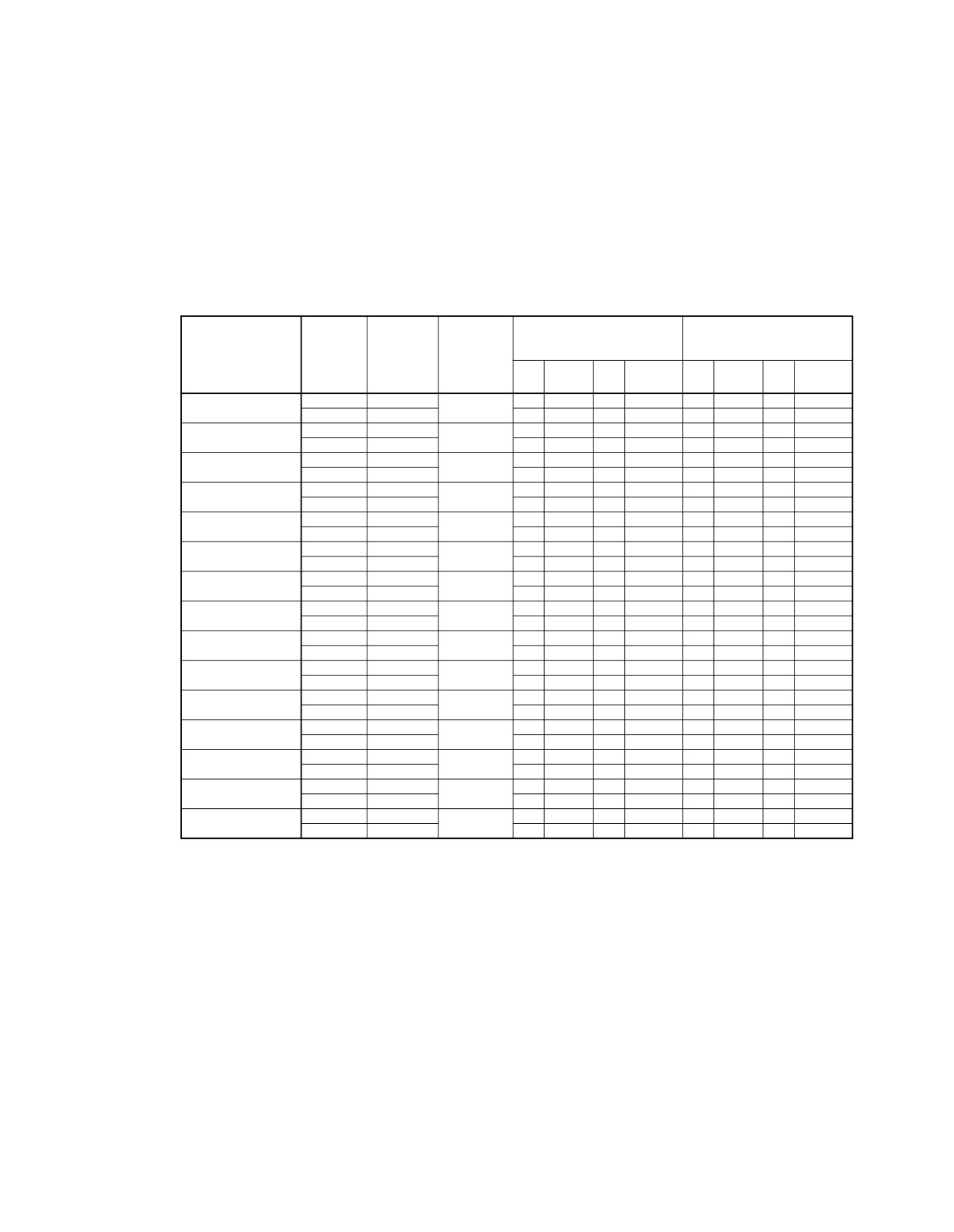
@A320
AIRCRAFT CHARACTERISTICS - AIRPORT AND MAINTENANCE PLANNING
**ON A/C A320-200
ACN FOR
ACN FOR
LOAD ON
RIGID PAVEMENT
TIRE
FLEXIBLE PAVEMENT
WEIGHT
ALL UP
ONE MAIN
SUBGRADES − MN/m?
SUBGRADES − CBR
PRESSURE
VARIANT
MASS (kg)
GEAR LEG
(MPa)
(%)
High
Medium
Low
Ultra−lowHigh
Medium
Low
Ultra−low
150
80
40
20
15
10
6
3
A320−200
71 900
47.2
40
43
45
47
37
38
43
49
1.14
WV013 (CG 41.42%)
42 000
47.2
21
23
24
26
20
20
22
26
A320−200
71 900
47.2
40
43
46
48
37
38
43
49
1.18
WV013 (CG 41.42%)
42 000
47.2
21
23
24
26
20
20
22
26
A320−200
71 900
47.2
39
41
44
47
36
38
43
49
1.03
WV013 (CG 41.42%)
42 000
47.2
20
22
24
25
19
20
22
25
A320−200
71 900
47.2
42
45
47
49
38
39
43
49
1.38
WV013 (CG 41%)
42 000
47.1
22
24
25
26
20
21
22
26
A320−200
71 900
47.2
40
43
45
47
37
38
43
49
1.14
WV013 (CG 41%)
42 000
47.1
21
23
24
25
20
20
22
26
A320−200
71 900
47.2
40
43
46
48
37
38
43
49
1.18
WV013 (CG 41%)
42 000
47.1
21
23
24
26
20
20
22
26
A320−200
71 900
47.2
38
41
44
46
36
38
42
49
1.03
WV013 (CG 41%)
42 000
47.1
20
22
24
25
19
20
22
25
A320−200
73 900
47.0
44
46
48
50
39
40
44
50
1.38
WV014
42 000
46.9
22
24
25
26
20
20
22
26
A320−200
73 900
47.0
41
44
46
49
38
39
44
50
1.14
WV014
42 000
46.9
21
23
24
25
20
20
22
25
A320−200
73 900
47.0
41
44
47
49
38
39
44
50
1.18
WV014
42 000
46.9
21
23
24
26
20
20
22
25
A320−200
73 900
47.0
40
43
45
48
37
39
44
50
1.03
WV014
42 000
46.9
20
22
23
25
19
20
22
25
A320−200
78 400
46.4
47
49
52
54
41
43
47
53
1.44
WV015
42 000
46.4
22
24
25
26
20
20
22
25
A320−200
73 900
47.0
44
46
48
50
39
40
44
50
1.38
WV016
42 000
46.9
22
24
25
26
20
20
22
26
A320−200
73 900
47.0
41
44
46
49
38
39
44
50
1.14
WV016
42 000
46.9
21
23
24
25
20
20
22
25
A320−200
73 900
47.0
41
44
47
49
38
39
44
50
1.18
WV016
42 000
46.9
21
23
24
26
20
20
22
25
N_AC_070900_1_0120105_01_02
Aircraft Classification Number
ACN Table (Sheet 5 of 7)
FIGURE-7-9-0-991-012-A01
Page 7
Dec 01/20
7-9-0
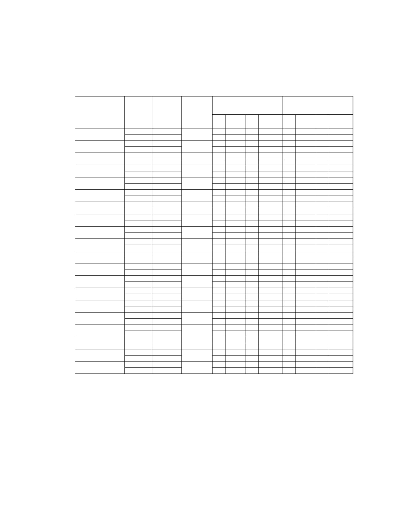
@A320
AIRCRAFT CHARACTERISTICS - AIRPORT AND MAINTENANCE PLANNING
**ON A/C A320-200
ACN FOR
ACN FOR
LOAD ON
TIRE
RIGID PAVEMENT
FLEXIBLE PAVEMENT
WEIGHT
ALL UP
ONE MAIN
SUBGRADES − MN/m?
SUBGRADES − CBR
PRESSURE
VARIANT
MASS (kg)
GEAR LEG
(MPa)
High
Medium
Low
Ultra−lowHigh
Medium
Low
Ultra−low
(%)
150
80
40
20
15
10
6
3
A320−200
73 900
47.0
40
43
45
48
37
39
44
50
1.03
WV016
42 000
46.9
20
22
23
25
19
20
22
25
A320−200
78 400
46.4
47
49
52
54
41
43
47
53
1.44
WV017
42 000
46.4
22
24
25
26
20
20
22
25
A320−200
71 900
47.2
42
45
47
49
38
39
43
49
1.38
WV018 (CG 41.46%)
42 000
47.2
23
24
25
26
20
21
22
26
A320−200
71 900
47.2
40
43
45
47
37
38
43
49
1.14
WV018 (CG 41.46%)
42 000
47.2
21
23
24
26
20
20
22
26
A320−200
71 900
47.2
40
43
46
48
37
38
43
49
1.18
WV018 (CG 41.46%)
42 000
47.2
21
23
24
26
20
20
22
26
A320−200
71 900
47.2
39
41
44
47
36
38
43
49
1.03
WV018 (CG 41.46%)
42 000
47.2
20
22
24
25
19
20
22
25
A320−200
71 900
47.2
42
45
47
49
38
39
43
49
1.38
WV018 (CG 41%)
42 000
47.1
22
24
25
26
20
21
22
26
A320−200
71 900
47.2
40
43
45
47
37
38
43
49
1.14
WV018 (CG 41%)
42 000
47.1
21
23
24
25
20
20
22
26
A320−200
71 900
47.2
40
43
46
48
37
38
43
49
1.18
WV018 (CG 41%)
42 000
47.1
21
23
24
26
20
20
22
26
A320−200
71 900
47.2
38
41
44
46
36
38
42
49
1.03
WV018 (CG 41%)
42 000
47.1
20
22
24
25
19
20
22
25
A320−201
71 900
47.2
42
45
47
49
38
39
43
49
1.38
WV018 (CG 41.4%)
42 000
47.2
23
24
25
26
20
21
22
26
A320−201
71 900
47.2
40
43
45
47
37
38
43
49
1.14
WV018 (CG 41.4%)
42 000
47.2
21
23
24
26
20
20
22
26
A320−201
71 900
47.2
40
43
46
48
37
38
43
49
1.18
WV018 (CG 41.4%)
42 000
47.2
21
23
24
26
20
20
22
26
A320−201
71 900
47.2
39
41
44
47
36
38
43
49
1.03
WV018 (CG 41.4%)
42 000
47.2
20
22
24
25
19
20
22
25
A320−202
71 900
47.2
42
45
47
49
38
39
43
49
1.38
WV018 (CG 41.47%)
42 000
47.2
23
24
25
26
20
21
22
26
A320−202
71 900
47.2
40
43
45
47
37
38
43
49
1.14
WV018 (CG 41.47%)
42 000
47.2
21
23
24
26
20
20
22
26
A320−202
71 900
47.2
40
43
46
48
37
38
43
49
1.18
WV018 (CG 41.47%)
42 000
47.2
21
23
24
26
20
20
22
26
A320−202
71 900
47.2
39
41
44
47
36
38
43
49
1.03
WV018 (CG 41.47%)
42 000
47.2
20
22
24
25
19
20
22
25
A320−200
70 400
47.3
40
43
45
47
36
37
42
48
1.28
WV019 (CG 42%)
42 000
47.3
22
23
25
26
20
21
22
26
A320−200
70 400
47.3
38
41
44
46
35
37
42
48
1.06
WV019 (CG 42%)
42 000
47.3
21
22
24
25
20
20
22
26
N_AC_070900_1_0120106_01_03
Aircraft Classification Number
ACN Table (Sheet 6 of 7)
FIGURE-7-9-0-991-012-A01
Page 8
Dec 01/20
7-9-0
@A320
AIRCRAFT CHARACTERISTICS - AIRPORT AND MAINTENANCE PLANNING
**ON A/C A320-200
ACN FOR
ACN FOR
LOAD ON
RIGID PAVEMENT
FLEXIBLE PAVEMENT
TIRE
WEIGHT
ALL UP
ONE MAIN
SUBGRADES − MN/m?
SUBGRADES − CBR
PRESSURE
VARIANT
MASS (kg)
GEAR LEG
(MPa)
(%)
High
Medium
Low
Ultra−lowHigh
Medium
Low
Ultra−low
150
80
40
20
15
10
6
3
A320−200
70 400
47.3
38
41
44
46
36
37
42
48
1.09
WV019 (CG 42%)
42 000
47.3
21
22
24
25
20
20
22
26
A320−200
70 400
47.3
37
40
43
45
35
36
41
48
0.96
WV019 (CG 42%)
42 000
47.3
20
22
23
25
19
20
22
26
A320−200
70 400
47.2
40
43
45
47
36
37
42
48
1.28
WV019 (CG 41%)
42 000
47.1
22
23
25
26
20
20
22
26
A320−200
70 400
47.2
38
41
43
46
35
37
41
47
1.06
WV019 (CG 41%)
42 000
47.1
21
22
24
25
20
20
22
25
A320−200
70 400
47.2
38
41
44
46
36
37
41
47
1.09
WV019 (CG 41%)
42 000
47.1
21
22
24
25
20
20
22
25
A320−200
70 400
47.2
37
40
42
45
35
36
41
47
0.96
WV019 (CG 41%)
42 000
47.1
20
21
23
25
19
20
22
25
A320−200
70 400
47.4
41
43
46
48
37
38
42
48
1.28
WV019 (CG 42.61%)
42 000
47.4
22
24
25
26
20
21
22
26
A320−200
70 400
47.4
38
41
44
46
36
37
42
48
1.06
WV019 (CG 42.61%)
42 001
47.4
21
22
24
25
20
20
22
26
A320−200
70 400
47.4
38
41
44
46
36
37
42
48
1.09
WV019 (CG 42.61%)
42 002
47.4
21
22
24
25
20
20
22
26
A320−200
70 400
47.4
37
40
43
45
35
37
41
48
0.96
WV019 (CG 42.61%)
42 003
47.4
20
22
23
25
19
20
22
26
A320−200
70 400
47.0
40
43
45
47
36
37
42
47
1.28
WV019 (CG 40%)
42 000
46.9
22
23
25
26
20
20
22
25
A320−200
70 400
47.0
38
41
43
45
35
37
41
47
1.06
WV019 (CG 40%)
42 001
46.9
20
22
24
25
20
20
22
25
A320−200
70 400
47.0
38
41
43
46
36
37
41
47
1.09
WV019 (CG 40%)
42 002
46.9
21
22
24
25
20
20
22
25
A320−200
70 400
47.0
36
39
42
45
34
36
41
47
0.96
WV019 (CG 40%)
42 003
46.9
20
21
23
24
19
20
22
25
A320−200
73 900
46.9
18
21
25
28
17
19
22
31
1.22
WV000 BOGIE
42 000
46.9
9
10
11
13
9
9
10
13
N_AC_070900_1_0120107_01_02
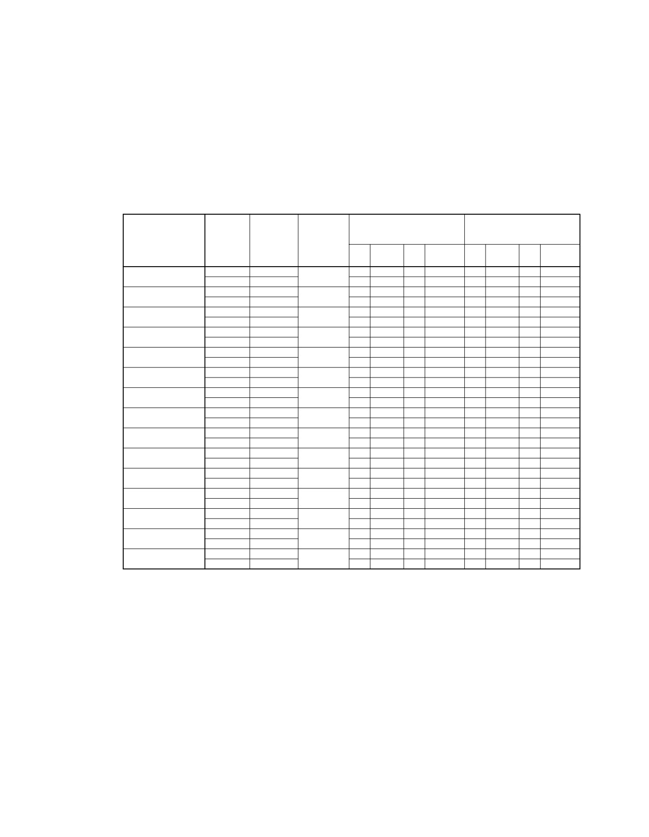
Aircraft Classification Number
ACN Table (Sheet 7 of 7)
FIGURE-7-9-0-991-012-A01
Page 9
Dec 01/20
7-9-0
@A320
AIRCRAFT CHARACTERISTICS - AIRPORT AND MAINTENANCE PLANNING
**ON A/C A320-200
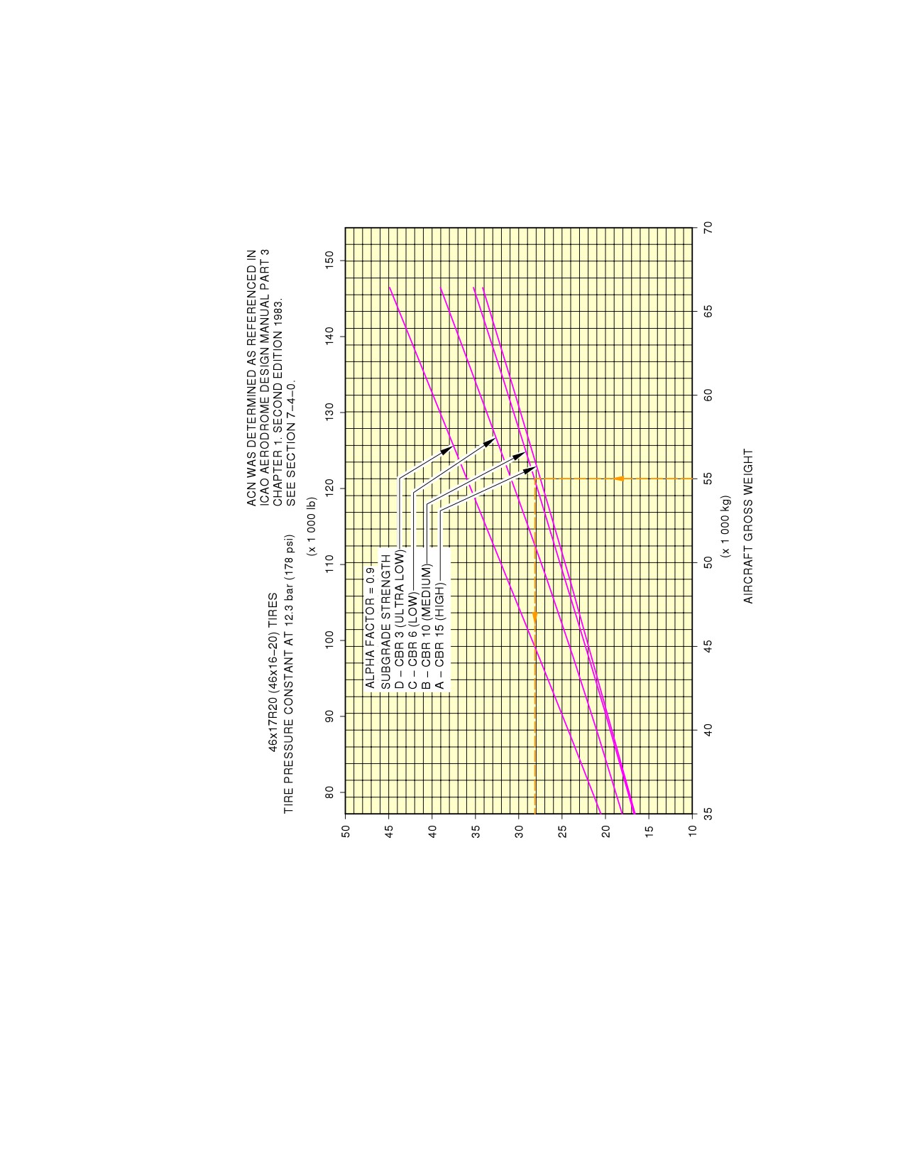
AIRCRAFT CLASSIFICATION NUMBER (ACN)
N_AC_070900_1_0130101_01_00
Aircraft Classification Number
Flexible Pavement - WV006, MRW 66 400 kg, CG 43 % (Sheet 1 of 2)
FIGURE-7-9-0-991-013-A01
Page 10
Dec 01/20
7-9-0
@A320
AIRCRAFT CHARACTERISTICS - AIRPORT AND MAINTENANCE PLANNING
**ON A/C A320-200
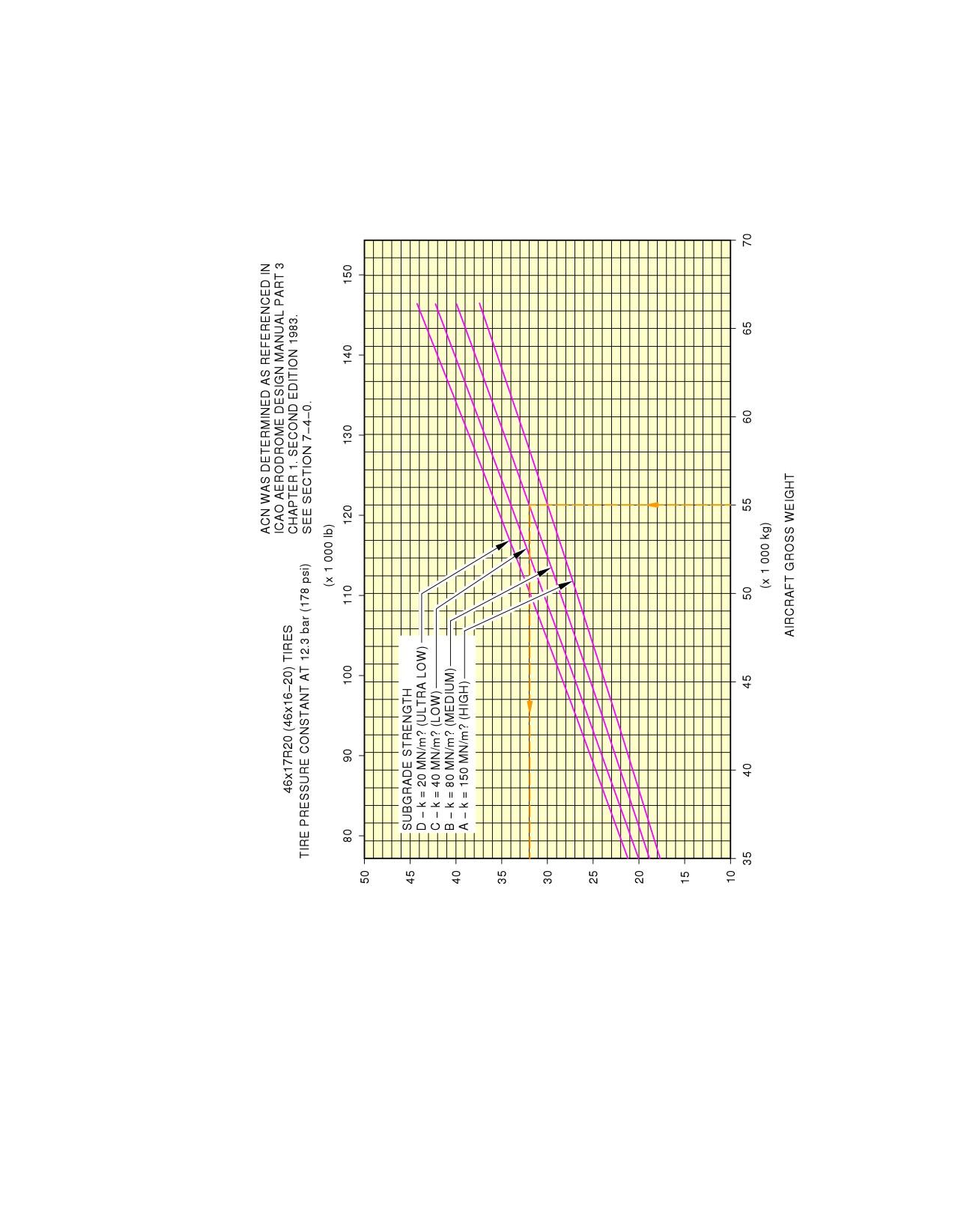
AIRCRAFT CLASSIFICATION NUMBER (ACN)
N_AC_070900_1_0130102_01_00
Aircraft Classification Number
Rigid Pavement - WV006, MRW 66 400 kg, CG 43 % (Sheet 2 of 2)
FIGURE-7-9-0-991-013-A01
Page 11
Dec 01/20
7-9-0
@A320
AIRCRAFT CHARACTERISTICS - AIRPORT AND MAINTENANCE PLANNING
**ON A/C A320-200
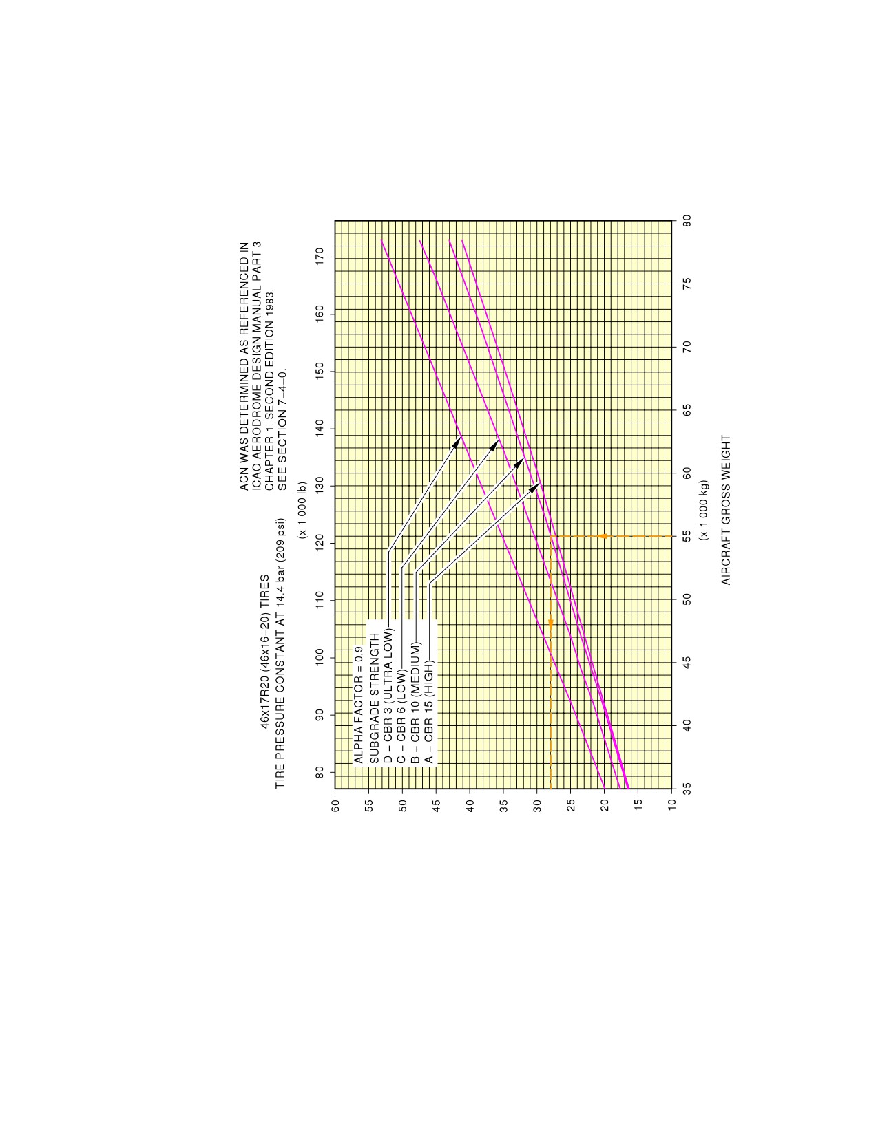
AIRCRAFT CLASSIFICATION NUMBER (ACN)
N_AC_070900_1_0140101_01_00
Aircraft Classification Number
Flexible Pavement - WV015, MRW 78 400 kg, CG 36.8 % (Sheet 1 of 2)
FIGURE-7-9-0-991-014-A01
Page 12
Dec 01/20
7-9-0
@A320
AIRCRAFT CHARACTERISTICS - AIRPORT AND MAINTENANCE PLANNING
**ON A/C A320-200
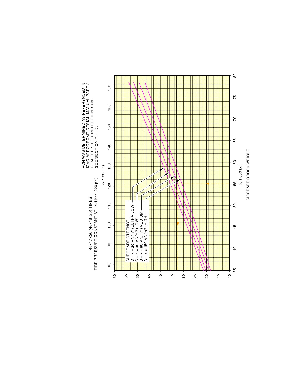
AIRCRAFT CLASSIFICATION NUMBER (ACN)
N_AC_070900_1_0140102_01_00
Aircraft Classification Number
Rigid Pavement - WV015, MRW 78 400 kg, CG 36.8 % (Sheet 2 of 2)
FIGURE-7-9-0-991-014-A01
Page 13
Dec 01/20
7-9-0
@A320
AIRCRAFT CHARACTERISTICS - AIRPORT AND MAINTENANCE PLANNING
**ON A/C A320-200
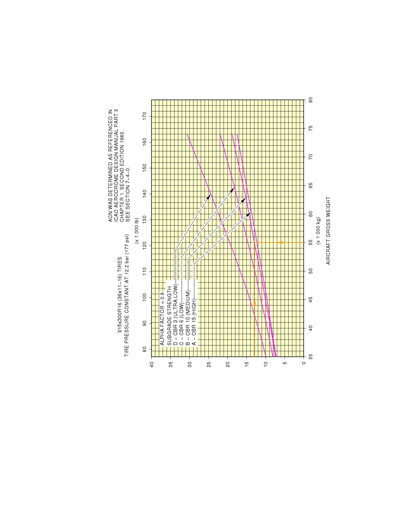
AIRCRAFT CLASSIFICATION NUMBER (ACN)
N_AC_070900_1_0150101_01_00
Aircraft Classification Number
Flexible Pavement - WV000 (Bogie), MRW 73 900 kg, CG 40 % (Sheet 1 of 2)
FIGURE-7-9-0-991-015-A01
Page 14
Dec 01/20
7-9-0
@A320
AIRCRAFT CHARACTERISTICS - AIRPORT AND MAINTENANCE PLANNING
**ON A/C A320-200
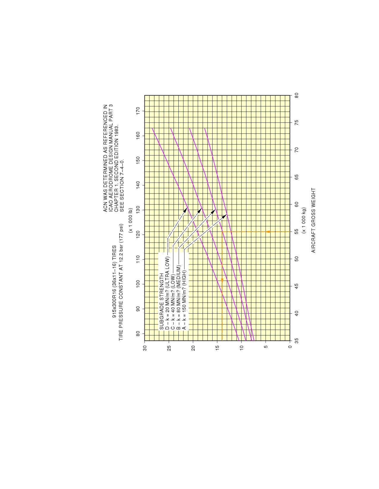
AIRCRAFT CLASSIFICATION NUMBER (ACN)
N_AC_070900_1_0150102_01_00
Aircraft Classification Number
Rigid Pavement - WV000 (Bogie), MRW 73 900 kg, CG 40 % (Sheet 2 of 2)
FIGURE-7-9-0-991-015-A01
Page 15
Dec 01/20
7-9-0
@A320
AIRCRAFT CHARACTERISTICS - AIRPORT AND MAINTENANCE PLANNING
**ON A/C A320neo
ACN FOR
ACN FOR
LOAD ON
RIGID PAVEMENT
FLEXIBLE PAVEMENT
TIRE
SUBGRADES − MN/m?
SUBGRADES − CBR
WEIGHT
ALL UP
ONE MAIN
PRESSURE
VARIANT
MASS (kg)
GEAR LEG
(MPa)
Ultra
Ultra
(%)
High
Medium
Low
High
Medium
Low
−low
−low
150
80
40
15
10
6
20
3
A320NEO
73 900
47.0
44
46
48
50
39
40
44
50
1.38
WV050
42 000
46.9
22
24
25
26
20
20
22
25
A320NEO
73 900
47.0
44
46
48
50
39
40
44
50
1.38
WV051
42 000
46.9
22
24
25
26
20
20
22
26
A320NEO
77 400
46.5
46
49
51
53
41
42
47
52
1.44
WV052
42 000
46.5
22
24
25
26
20
20
22
25
A320NEO
77 400
46.5
46
49
51
53
41
42
47
52
1.44
WV053
42 000
46.5
22
24
25
26
20
20
22
25
A320NEO
79 400
46.3
47
50
52
54
41
43
48
54
1.44
WV054
42 000
46.3
22
24
25
26
20
20
22
25
A320NEO
79 400
46.3
47
50
52
54
41
43
48
54
1.44
WV055
42 000
46.3
22
24
25
26
20
20
22
25
A320NEO
70 400
47.2
40
43
45
47
36
37
42
48
1.28
WV056
42 000
47.1
22
23
25
26
20
20
22
26
A320NEO
70 400
47.0
40
43
45
47
36
37
42
47
1.28
WV057
42 000
46.9
22
23
25
26
20
20
22
25
A320NEO
75 900
46.7
45
47
50
52
40
41
46
52
1.38
WV068
42 000
46.7
22
24
25
26
20
20
22
25
A320NEO
75 900
46.7
45
47
50
52
40
41
46
52
1.38
WV069
42 000
46.7
22
24
25
26
20
20
22
25
A320NEO
75 400
46.8
44
47
49
51
39
41
45
51
1.38
WV071
42 000
46.7
22
24
25
26
20
20
22
25
A320NEO
74 400
46.9
44
46
49
51
39
40
45
51
1.38
WV075
42 001
46.9
22
24
25
26
20
20
22
25
A320NEO
72 900
47.0
43
45
48
50
38
39
44
50
1.38
WV078
42 000
46.9
22
24
25
26
20
20
22
26
A320NEO
71 900
47.0
42
45
47
49
37
39
43
49
1.38
WV082
42 000
46.9
22
24
25
26
20
20
22
26
A320NEO
71 900
47.0
42
45
47
49
37
39
43
49
1.38
WV083
42 000
46.9
22
24
25
26
20
20
22
26
A320NEO
71 400
47.0
42
44
47
48
37
38
43
48
1.38
WV085
42 000
46.9
22
24
25
26
20
20
22
26
N_AC_070900_1_0160101_01_05
Aircraft Classification Number
ACN Table
FIGURE-7-9-0-991-016-A01
Page 16
Dec 01/20
7-9-0
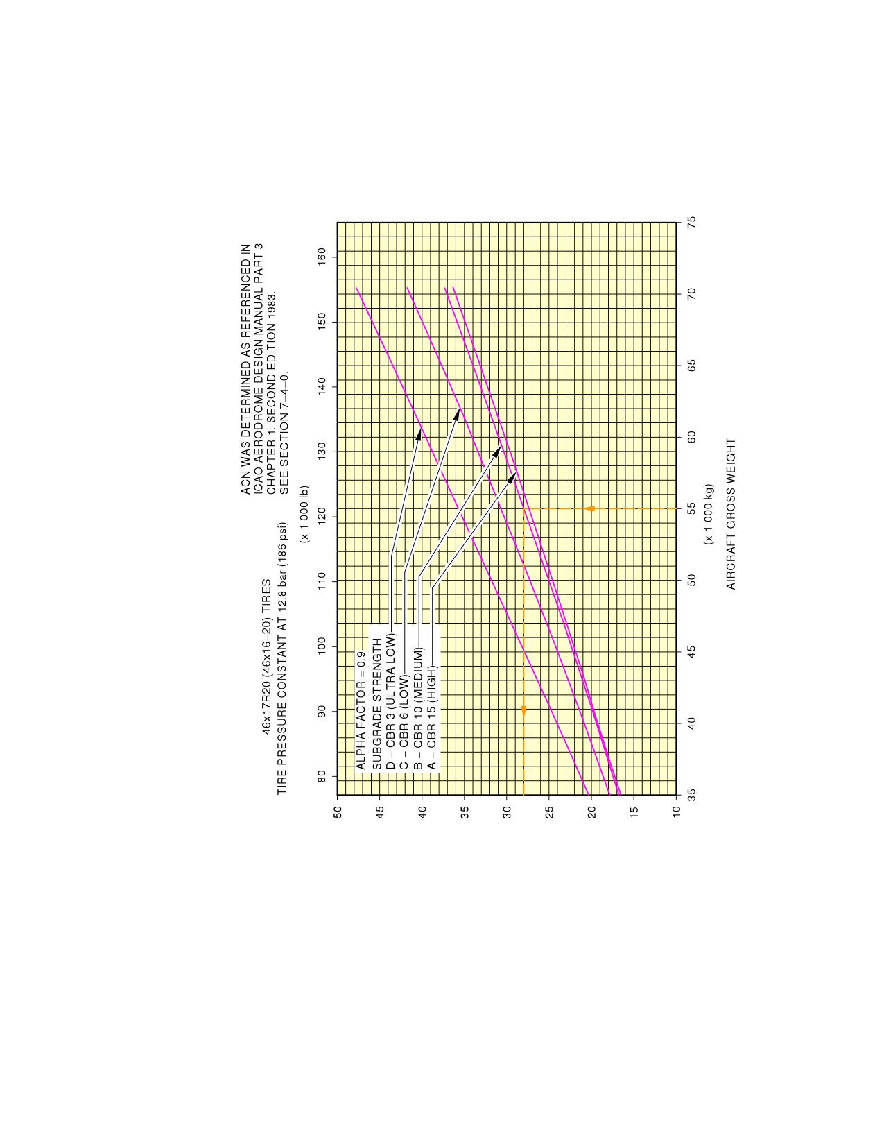
@A320
AIRCRAFT CHARACTERISTICS - AIRPORT AND MAINTENANCE PLANNING
**ON A/C A320neo
AIRCRAFT CLASSIFICATION NUMBER (ACN)
N_AC_070900_1_0170101_01_00
Aircraft Classification Number
Flexible Pavement - WV057, MRW 70 400 kg, CG 40 % (Sheet 1 of 2)
FIGURE-7-9-0-991-017-A01
Page 17
Dec 01/20
7-9-0
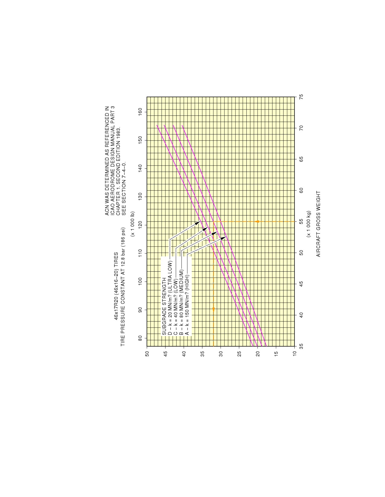
@A320
AIRCRAFT CHARACTERISTICS - AIRPORT AND MAINTENANCE PLANNING
**ON A/C A320neo
AIRCRAFT CLASSIFICATION NUMBER (ACN)
N_AC_070900_1_0170102_01_00
Aircraft Classification Number
Rigid Pavement - WV057, MRW 70 400 kg, CG 40 % (Sheet 2 of 2)
FIGURE-7-9-0-991-017-A01
Page 18
Dec 01/20
7-9-0
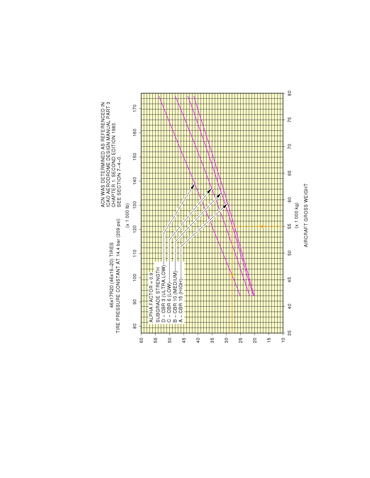
@A320
AIRCRAFT CHARACTERISTICS - AIRPORT AND MAINTENANCE PLANNING
**ON A/C A320neo
AIRCRAFT CLASSIFICATION NUMBER (ACN)
N_AC_070900_1_0180101_01_01
Aircraft Classification Number
Flexible Pavement - WV054, MRW 79 400 kg, CG 36.1 % (Sheet 1 of 2)
FIGURE-7-9-0-991-018-A01
Page 19
Dec 01/20
7-9-0
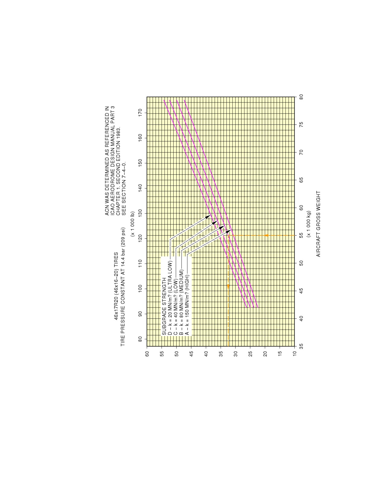
@A320
AIRCRAFT CHARACTERISTICS - AIRPORT AND MAINTENANCE PLANNING
**ON A/C A320neo
AIRCRAFT CLASSIFICATION NUMBER (ACN)
N_AC_070900_1_0180102_01_01
Aircraft Classification Number
Rigid Pavement - WV054, MRW 79 400 kg, CG 36.1 % (Sheet 2 of 2)
FIGURE-7-9-0-991-018-A01
Page 20
Dec 01/20
7-9-0
@A320
AIRCRAFT CHARACTERISTICS - AIRPORT AND MAINTENANCE PLANNING
SCALED DRAWINGS
8-0-0
SCALED DRAWINGS
**ON A/C A320-200 A320neo
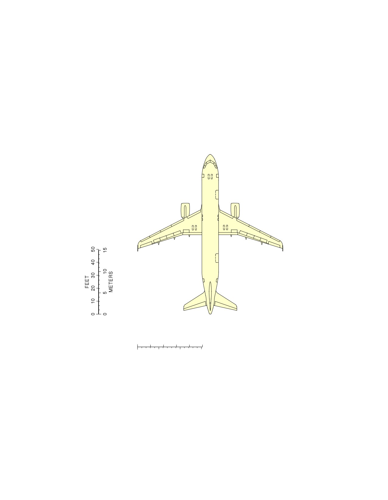
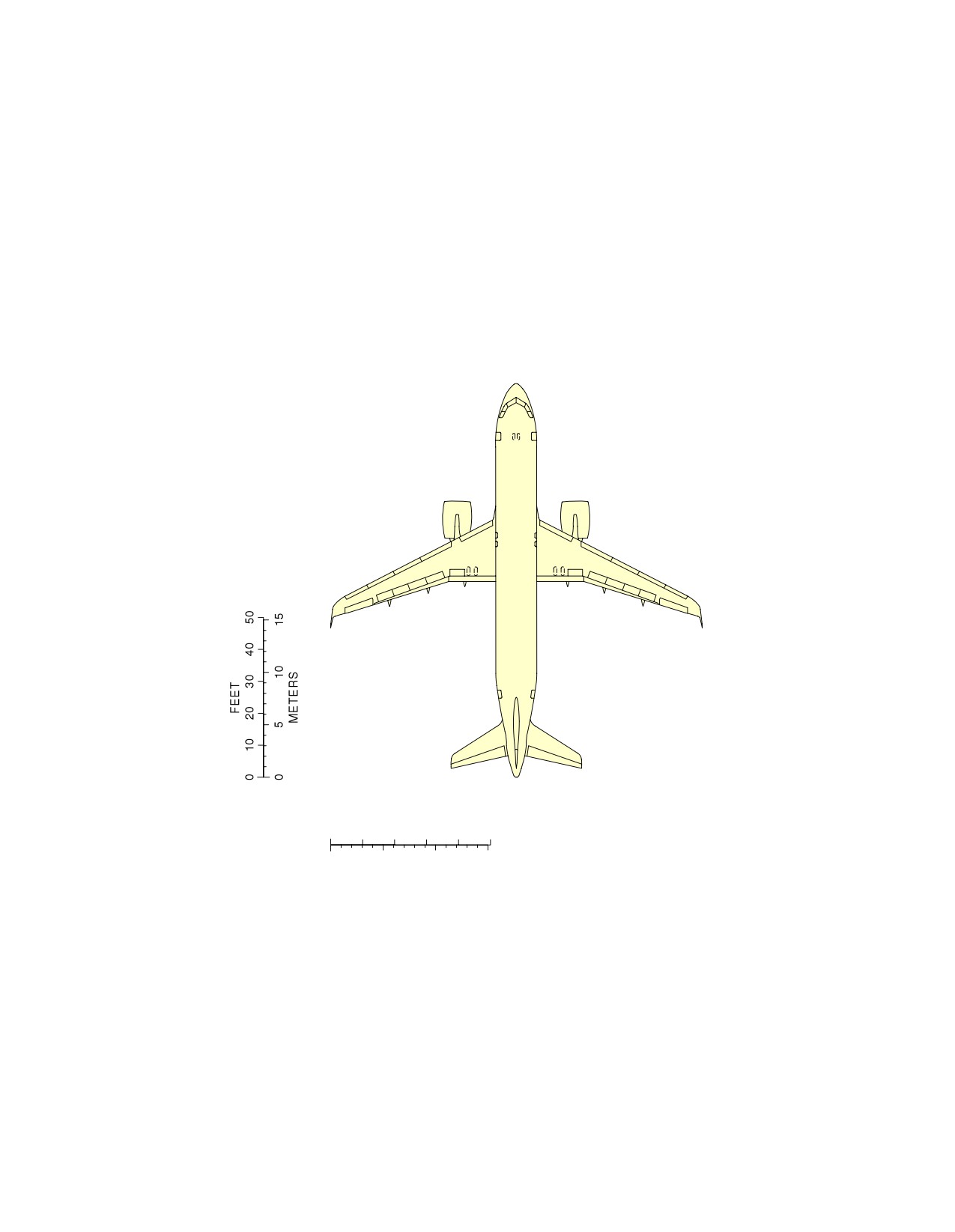
Scaled Drawings
1.
This section provides the scaled drawings.
NOTE : When printing this drawing, make sure to adjust for proper scaling.
Page 1
Dec 01/20
8-0-0
@A320
AIRCRAFT CHARACTERISTICS - AIRPORT AND MAINTENANCE PLANNING
**ON A/C A320-200
FEET
0
10
20
30
40
50
0
5
10
15
METERS
NOTE: WHEN PRINTING THIS DRAWING, MAKE SURE TO ADJUST FOR PROPER SCALING.
N_AC_080000_1_0030101_01_00
Scaled Drawing
FIGURE-8-0-0-991-003-A01
Page 2
Dec 01/20
8-0-0
@A320
AIRCRAFT CHARACTERISTICS - AIRPORT AND MAINTENANCE PLANNING
**ON A/C A320neo
FEET
0
10
20
30
40
50
0
5
10
15
METERS
NOTE:
WHEN PRINTING THIS DRAWING, MAKE SURE TO ADJUST FOR PROPER SCALING.
N_AC_080000_1_0060101_01_00
Scaled Drawing
FIGURE-8-0-0-991-006-A01
Page 3
Dec 01/20
8-0-0
@A320
AIRCRAFT CHARACTERISTICS - AIRPORT AND MAINTENANCE PLANNING
AIRCRAFT RESCUE AND FIRE FIGHTING
10-0-0
AIRCRAFT RESCUE AND FIRE FIGHTING
**ON A/C A320-200 A320neo
Aircraft Rescue and Fire Fighting
1.
Aircraft Rescue and Fire Fighting Charts
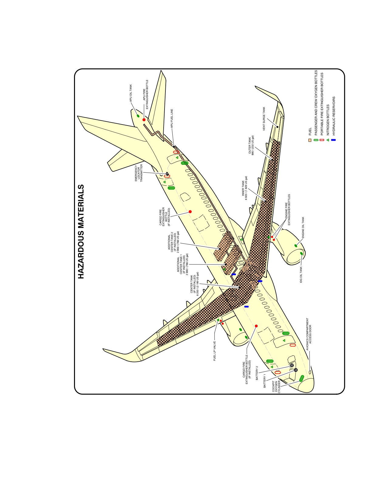
This sections provides data related to aircraft rescue and fire fighting.
The figures contained in this section are the figures that are in the Aircraft Rescue and Fire Fighting
Charts poster available for download on AIRBUSWorld and the Airbus website.
Page 1
Dec 01/20
10-0-0
@A320
AIRCRAFT CHARACTERISTICS - AIRPORT AND MAINTENANCE PLANNING
**ON A/C A320-200 A320neo
N_AC_100000_1_0300101_01_04
Front Page
FIGURE-10-0-0-991-030-A01
Page 2
Dec 01/20
10-0-0
@A320
AIRCRAFT CHARACTERISTICS - AIRPORT AND MAINTENANCE PLANNING
**ON A/C A320-200 A320neo
N_AC_100000_1_0310101_01_02
Highly Flammable and Hazardous Materials and Components
FIGURE-10-0-0-991-031-A01
Page 3
Dec 01/20
10-0-0
@A320
AIRCRAFT CHARACTERISTICS - AIRPORT AND MAINTENANCE PLANNING
**ON A/C A320-200 A320neo
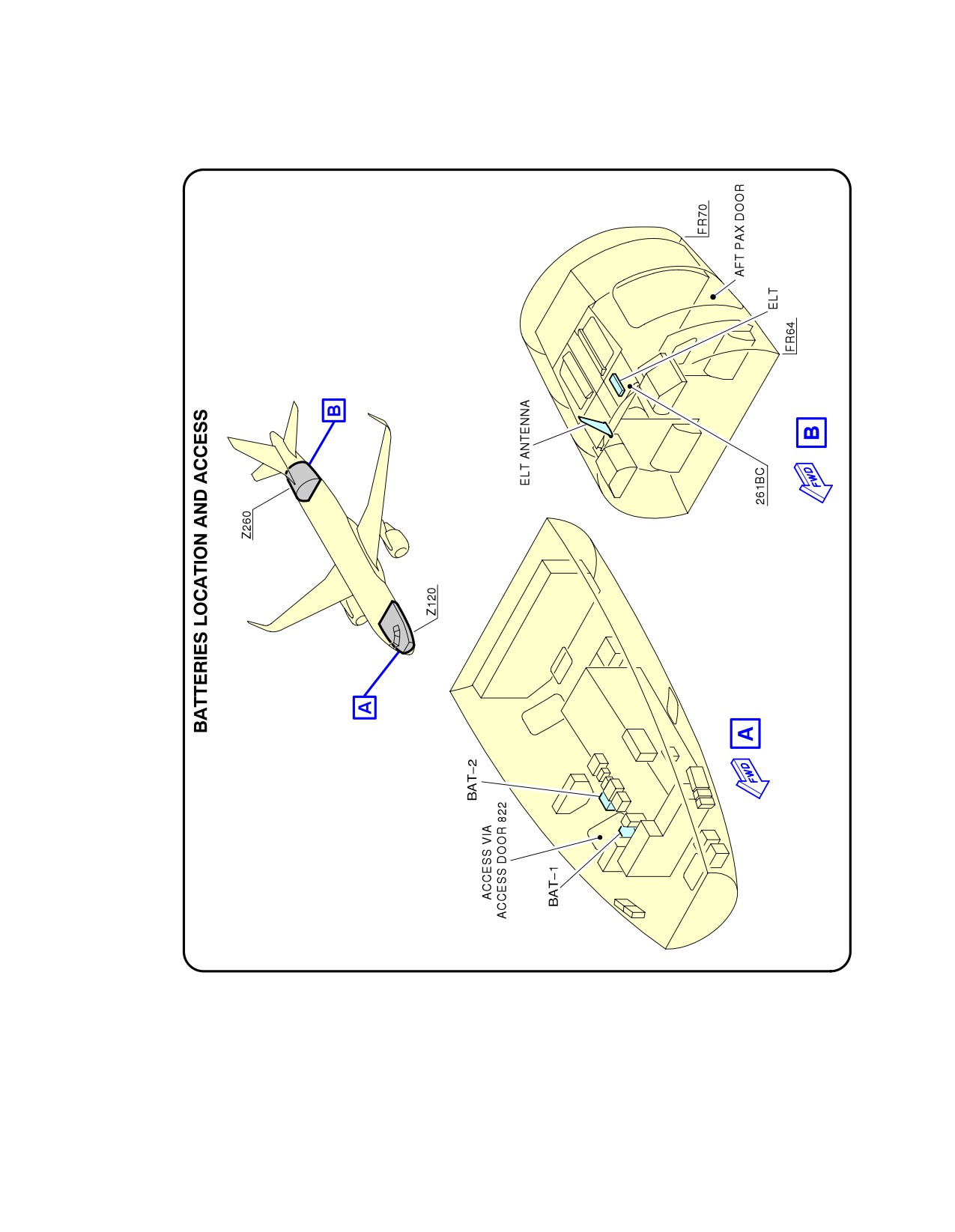
N_AC_100000_1_0570101_01_02
Batteries Location and Access
FIGURE-10-0-0-991-057-A01
Page 4
Dec 01/20
10-0-0
@A320
AIRCRAFT CHARACTERISTICS - AIRPORT AND MAINTENANCE PLANNING
**ON A/C A320-200 A320neo
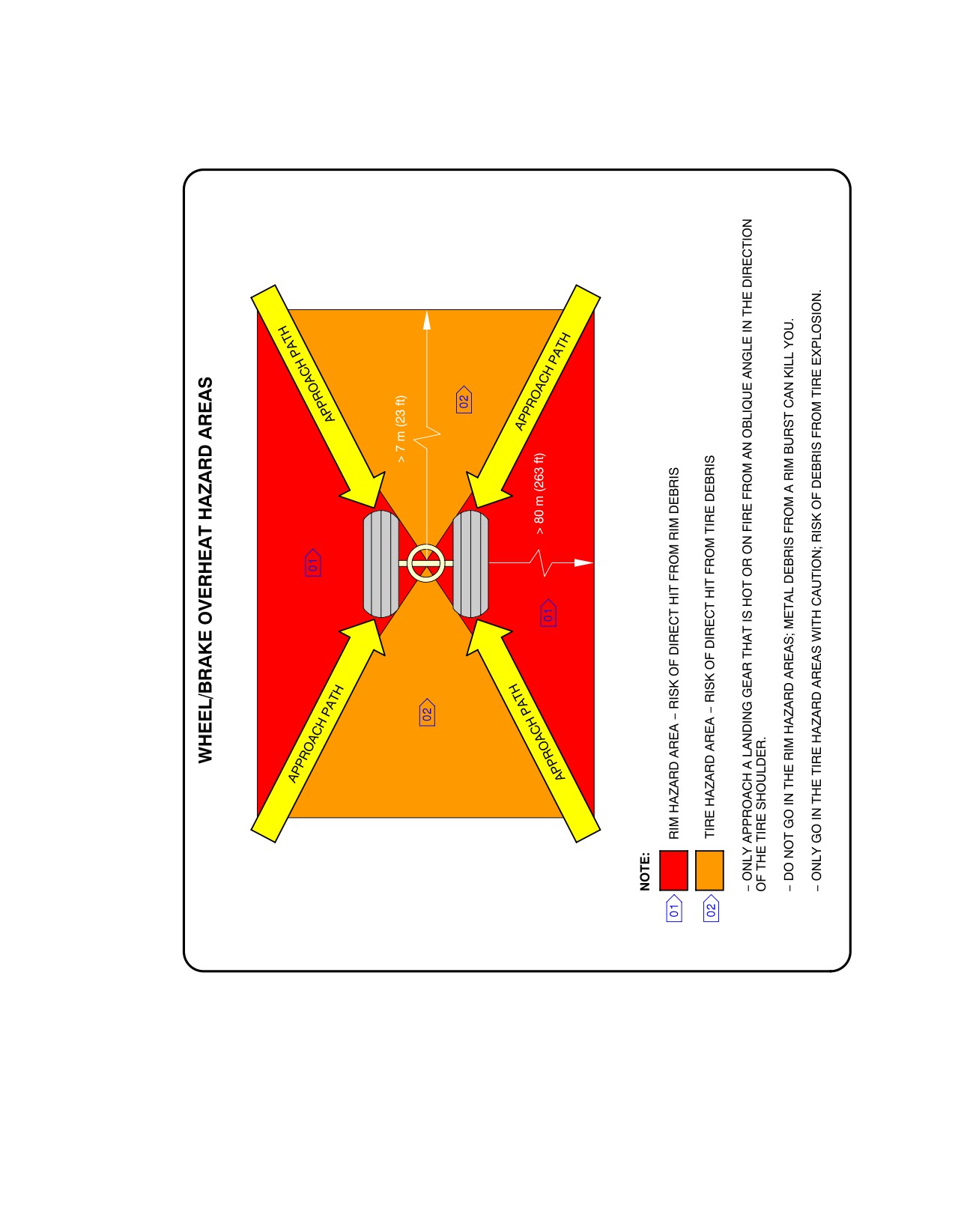
N_AC_100000_1_0320101_01_02
Wheel/Brake Overheat
Wheel Safety Area (Sheet 1 of 2)
FIGURE-10-0-0-991-032-A01
Page 5
Dec 01/20
10-0-0
@A320
AIRCRAFT CHARACTERISTICS - AIRPORT AND MAINTENANCE PLANNING
**ON A/C A320-200 A320neo
N_AC_100000_1_0320102_01_00
Wheel/Brake Overheat
Recommendations (Sheet 2 of 2)
FIGURE-10-0-0-991-032-A01
Page 6
Dec 01/20
10-0-0
@A320
AIRCRAFT CHARACTERISTICS - AIRPORT AND MAINTENANCE PLANNING
**ON A/C A320-200 A320neo
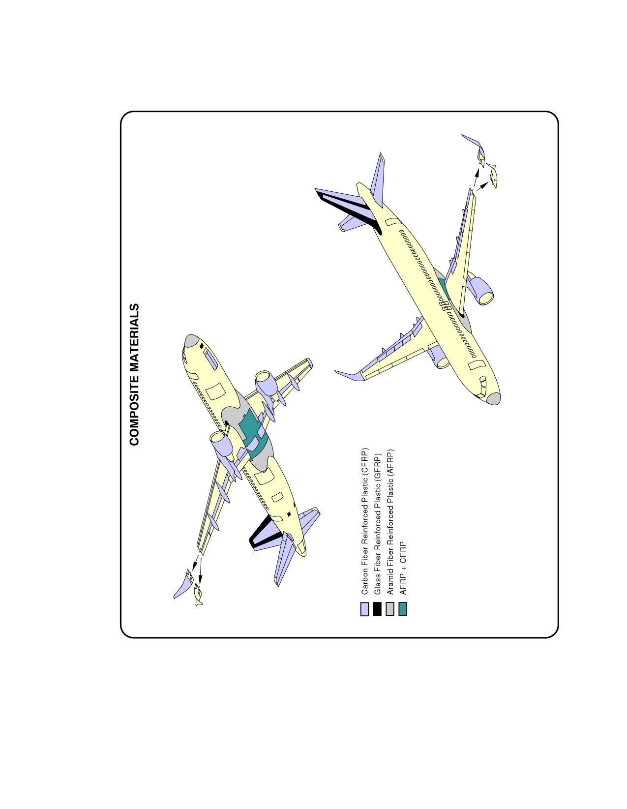
N_AC_100000_1_0330101_01_00
Composite Materials
FIGURE-10-0-0-991-033-A01
Page 7
Dec 01/20
10-0-0
@A320
AIRCRAFT CHARACTERISTICS - AIRPORT AND MAINTENANCE PLANNING
**ON A/C A320-200 A320neo
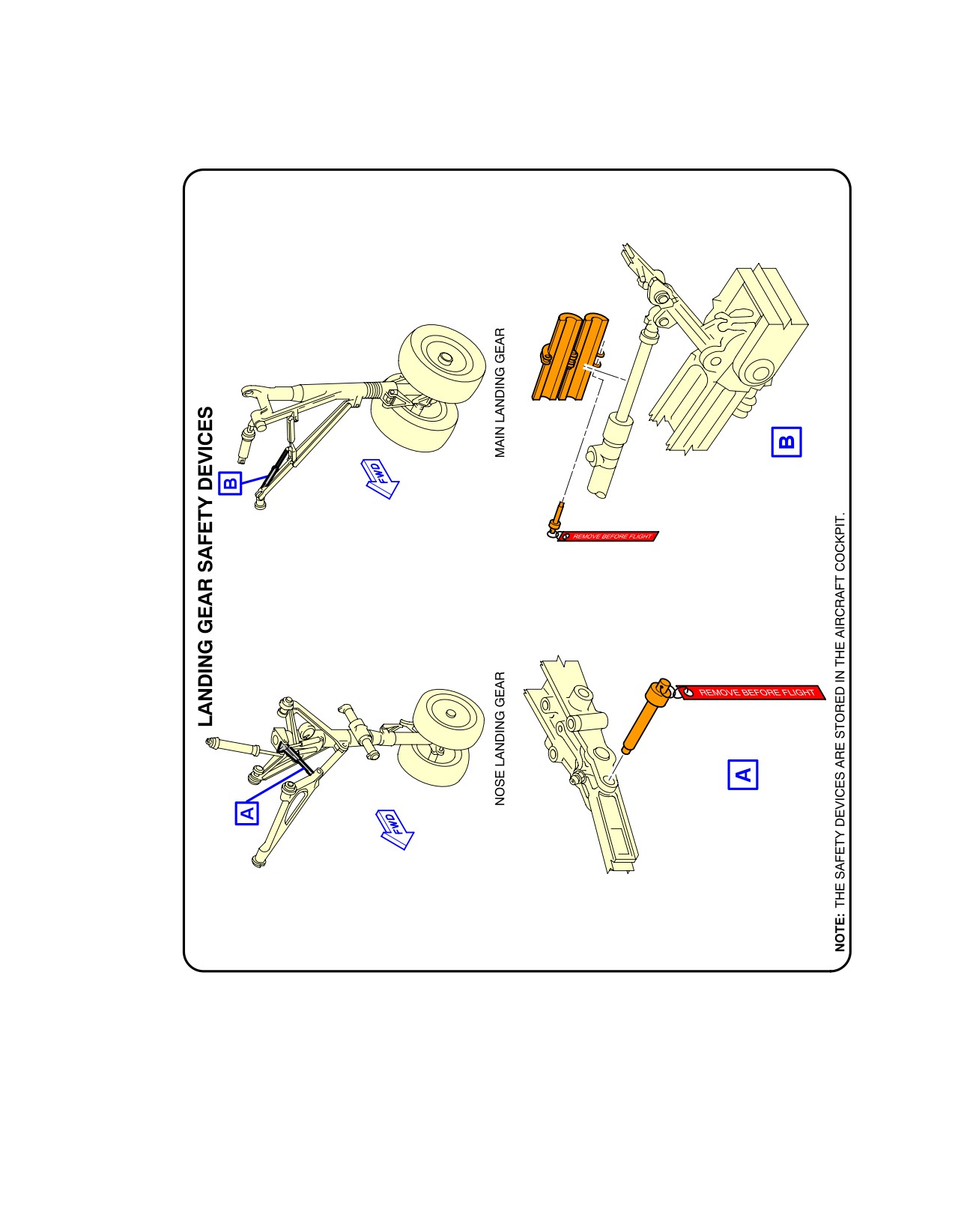
N_AC_100000_1_0340101_01_01
L/G Ground Lock Safety Devices
FIGURE-10-0-0-991-034-A01
Page 8
Dec 01/20
10-0-0
@A320
AIRCRAFT CHARACTERISTICS - AIRPORT AND MAINTENANCE PLANNING
**ON A/C A320-200 A320neo
N_AC_100000_1_0350101_01_04
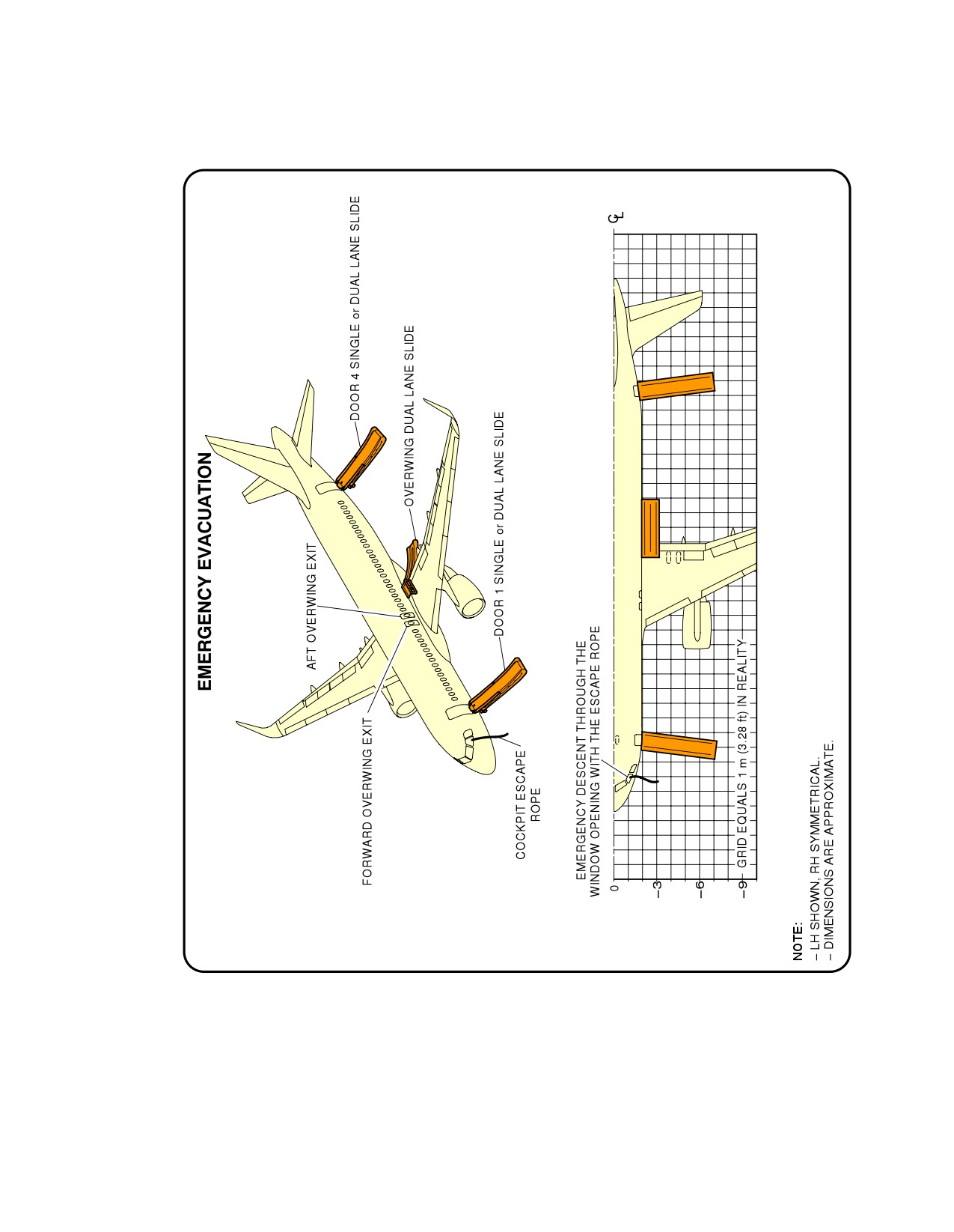
Emergency Evacuation Devices
FIGURE-10-0-0-991-035-A01
Page 9
Dec 01/20
10-0-0
@A320
AIRCRAFT CHARACTERISTICS - AIRPORT AND MAINTENANCE PLANNING
**ON A/C A320-200 A320neo
N_AC_100000_1_0360101_01_01
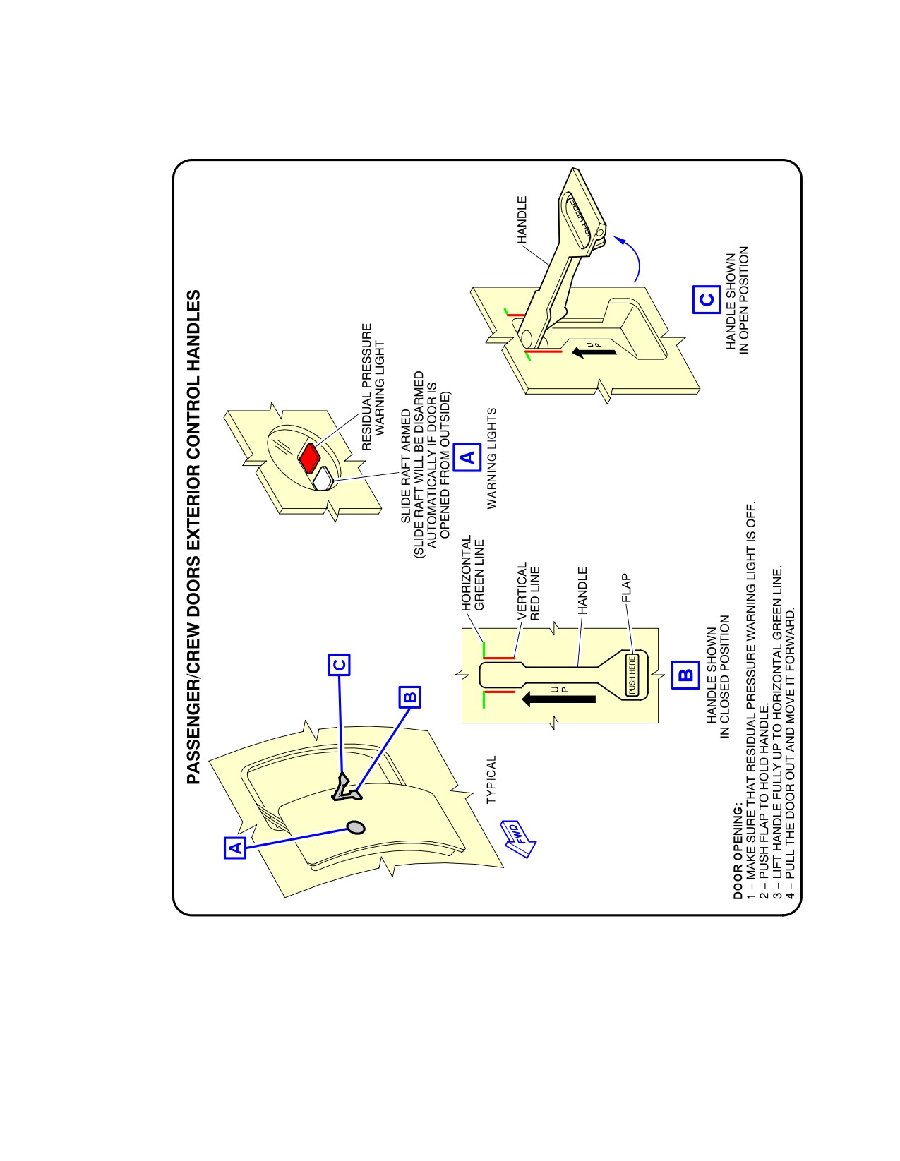
Pax/Crew Doors
FIGURE-10-0-0-991-036-A01
Page 10
Dec 01/20
10-0-0
@A320
AIRCRAFT CHARACTERISTICS - AIRPORT AND MAINTENANCE PLANNING
**ON A/C A320-200 A320neo
N_AC_100000_1_0370101_01_01
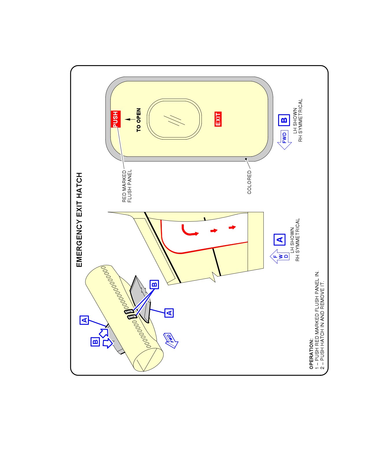
Emergency Exit Hatch
FIGURE-10-0-0-991-037-A01
Page 11
Dec 01/20
10-0-0
@A320
AIRCRAFT CHARACTERISTICS - AIRPORT AND MAINTENANCE PLANNING
**ON A/C A320-200 A320neo
N_AC_100000_1_0380101_01_01
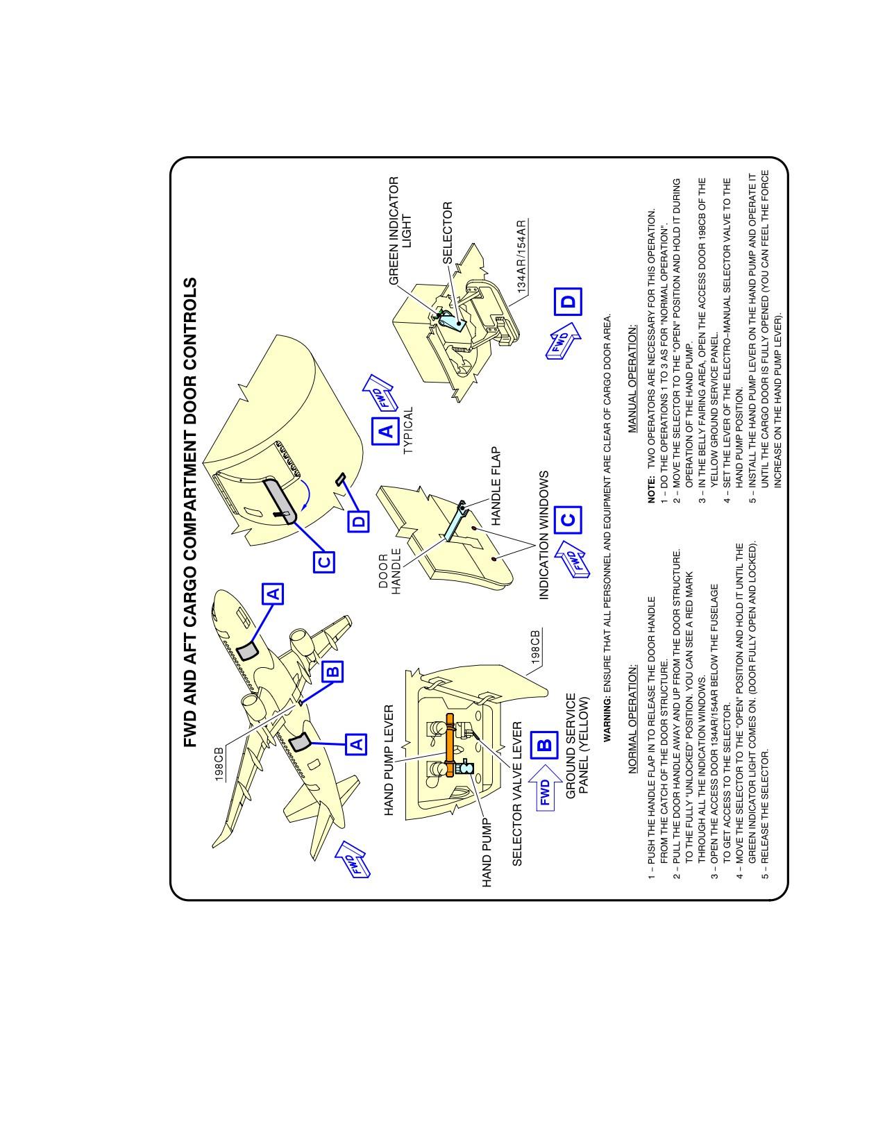
FWD and AFT Lower Deck Cargo Doors
FIGURE-10-0-0-991-038-A01
Page 12
Dec 01/20
10-0-0
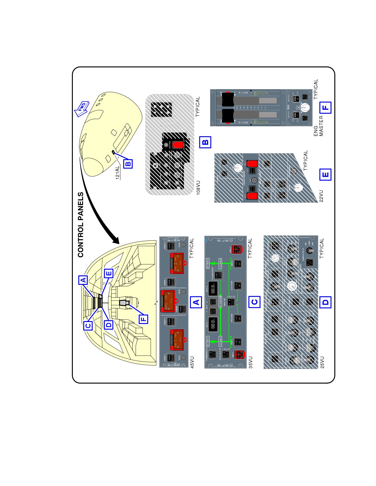
@A320
AIRCRAFT CHARACTERISTICS - AIRPORT AND MAINTENANCE PLANNING
**ON A/C A320-200 A320neo
N_AC_100000_1_0390101_01_01
Control Panels
FIGURE-10-0-0-991-039-A01
Page 13
Dec 01/20
10-0-0
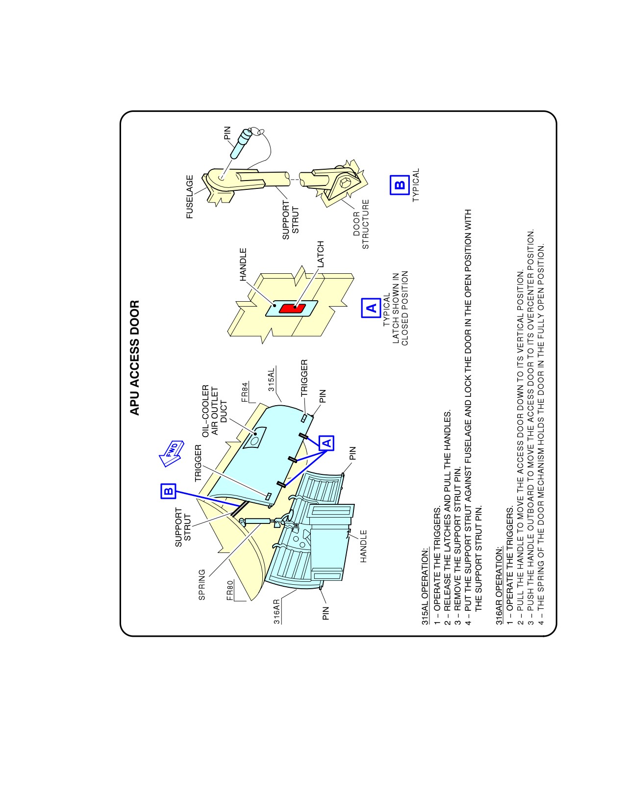
@A320
AIRCRAFT CHARACTERISTICS - AIRPORT AND MAINTENANCE PLANNING
**ON A/C A320-200 A320neo
N_AC_100000_1_0400101_01_01
APU Access Door
FIGURE-10-0-0-991-040-A01
Page 14
Dec 01/20
10-0-0
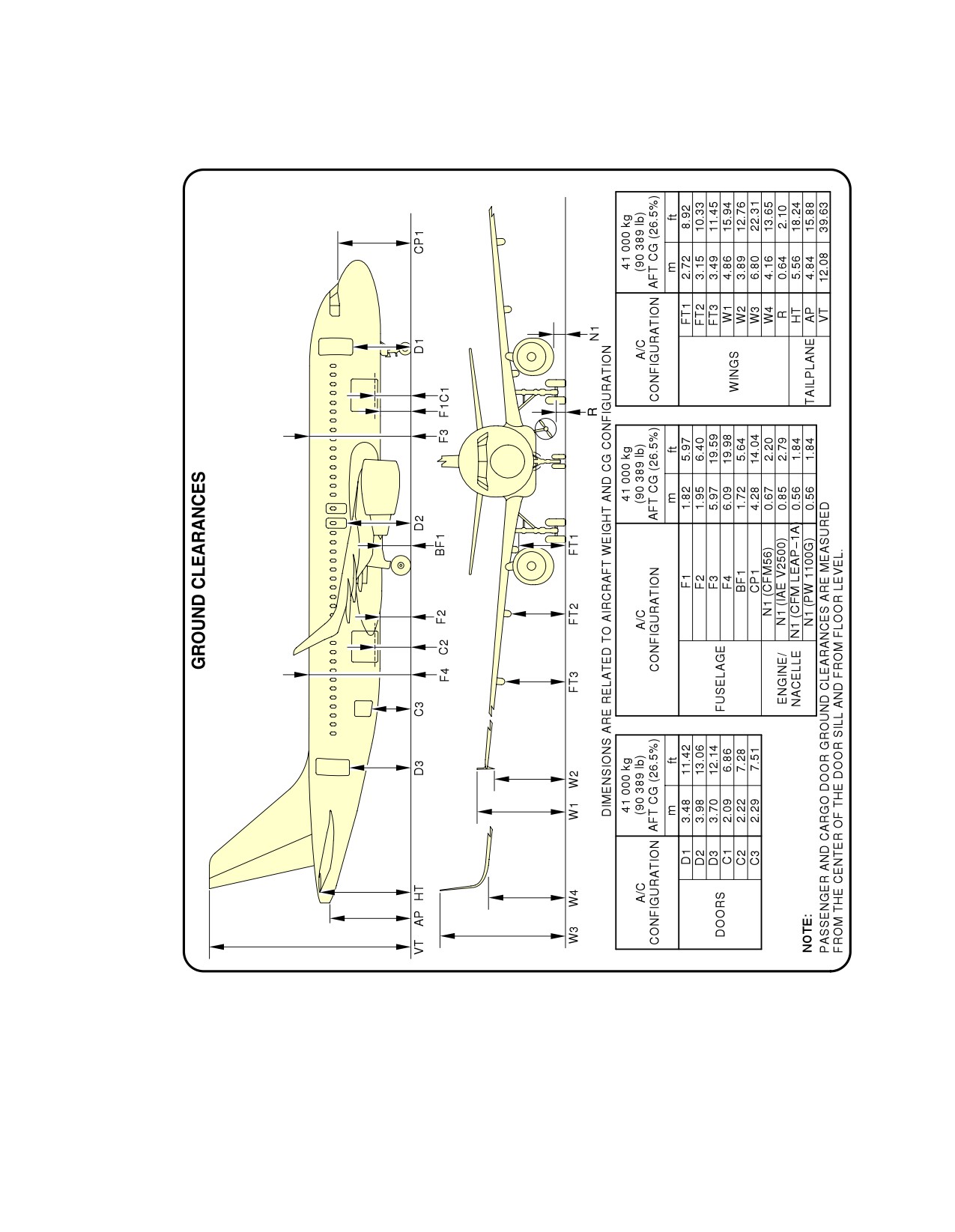
@A320
AIRCRAFT CHARACTERISTICS - AIRPORT AND MAINTENANCE PLANNING
**ON A/C A320-200 A320neo
N_AC_100000_1_0410101_01_02
Aircraft Ground Clearances
FIGURE-10-0-0-991-041-A01
Page 15
Dec 01/20
10-0-0
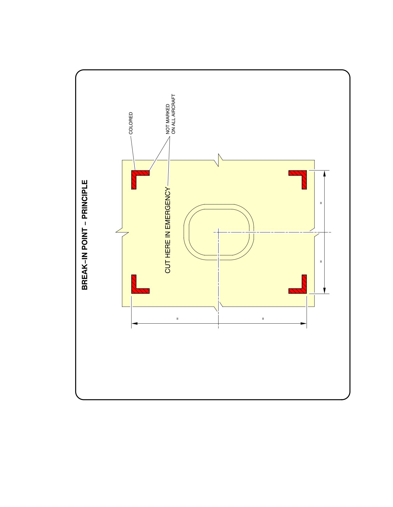
@A320
AIRCRAFT CHARACTERISTICS - AIRPORT AND MAINTENANCE PLANNING
**ON A/C A320-200 A320neo
N_AC_100000_1_0420101_01_01
Structural Break-in Points
FIGURE-10-0-0-991-042-A01
Page 16
Dec 01/20
10-0-0
- E. TARNOWSKI -
A320 INSTRUCTOR SUPPORT
The purpose of this document is to supply some background and concentrating knowledge and to
be an assistance for Instructors in terms of properly delivering their briefing and in order to be
ready to answer trainees questions.
This document does not replace the FCOMs, which are the reference.
This document outlines furthermore the WHYs of most of the recommended procedures, suggests
some efficient practices, which best suit the intended Cockpit Design Philosophy.
Consequently, while the briefing notes describe the specific issues which have to be covered by
instructors on given topics, the Instructor Support document provides the arguments needed by
them to efficiently brief the trainees on those given topics.
This document supports the instructors standardisation requirements.
Finally, flight instructors will refer to the Instructor Support document in order to carry out the
briefings required during IOE.
THIS DOCUMENT IS FOR INTERNAL USE ONLY
A320 INSTRUCTOR SUPPORT
CONTENTS
A320 INSTRUCTOR SUPPORT
SUMMARY
__________________________
A - NORMAL OPERATION
1 -
AIRCRAFT DOCUMENTATION
3
2 -
COCKPIT PREPARATION AND SOME CG CONSIDERATIONS
5
3 -
TAKE OFF BRIEFING
13
4 -
ENGINE START
14
5 -
TAXI AND BRAKING
16
6 -
TAKE OFF
20
7 -
CLIMB
24
8 -
CRUISE MANAGEMENT
27
9 -
CRUISE - DESCENT AND APPROACH PREPARATION - APPROACH BRIEFING
33
10 -
DESCENT
35
11 -
APPROACHES
41
11/1
- GENERAL APPROACH BRIEFING
42
11/2
- ILS APPROACH
47
11/3
- NON PRECISION APPROACHES (NPA)
51
11/4
- CIRCLING APPROACH
56
11/5
- VISUAL APPROACH
58
DATE: JAN 2001
Page i
UDYXX02
A320 INSTRUCTOR SUPPORT
CONTENTS
12 -
PRECISION APPROACHES - CAT II - CAT III
59
13 -
VAPP DETERMINATION
66
14 -
LANDING, FLARE, ROLLOUT AND BRAKING
70
15 -
GO AROUND
80
16 -
ETOPS
82
17 -
RVSM
90
18 -
PERFORMANCE CONSIDERATIONS
92
19 -
USE OF FLYING REFERENCES - ATTITUDE OR BIRD (FPV)
108
20 -
USE OF AP/FD
110
21 -
USE OF ATHR
113
22 -
FLIGHT DIRECTOR / AUTOPILOT / ATHR - MODE CHANGES AND REVERSIONS
118
23 -
FMS NAVIGATION ACCURACY - CROSSCHECK, POSITION UPDATE, GPS
122
24 -
FLIGHT CONTROLS - HIGHLIGHTS ON HANDLING CHARACTERISTICS
129
25 -
FLIGHT CONTROLS - HIGHLIGHTS ON THE PROTECTIONS
136
26 -
PREDICTIVE AND REACTIVE WINDSHEAR
140
27 -
EGPWS AND GPWS
147
28 -
TCAS II
152
29 -
USE OF RADAR
157
30 -
ADVERSE WEATHER OPERATIONS
163
31 -
FERRY FLIGHT WITH LANDING GEAR DOWN
169
32 -
WET AND CONTAMINATED RUNWAYS
170
DATE: JAN 2001
Page ii
UDYXX02
A320 INSTRUCTOR SUPPORT
CONTENTS
B - ABNORMAL OPERATION
1 - ECAM PHILOSOPHY
175
2 - REJECTED TAKE-OFF (REFER FCOM 3-02-01)
181
3 - ENGINE FAILURE/FIRE AFTER V1
183
4 - FAILURE OF SOME ENGINE COMPONENTS
185
5 - EMERGENCY ELECTRICAL CONFIGURATION
187
6 - DOUBLE HYDRAULIC FAILURE
190
7 - ABNORMAL SLATS/FLAPS
192
8 - ZFW ENTRY ERROR (PILOT’S ENTRY)
194
9 - DOUBLE RADIO ALTIMETER FAILURE
197
10 - UNRELIABLE SPEED/ALTITUDE INDICATION
199
DATE: JAN 2001
Page iii
UDYXX02
A320 INSTRUCTOR SUPPORT
CONTENTS
THIS PAGE INTENTIONALLY LEFT BLANK
DATE: JAN 2001
Page iv
UDYXX02
A320 INSTRUCTOR SUPPORT
NORMAL OPERATION
A. NORMAL OPERATION
DATE: JAN 2001
Page 1
UDY0102
A320 INSTRUCTOR SUPPORT
NORMAL OPERATION
THIS PAGE INTENTIONALLY LEFT BLANK
DATE: JAN 2001
Page 2
UDY0102

A320 INSTRUCTOR SUPPORT
NORMAL OPERATION
1 - AIRCRAFT DOCUMENTATION
!
The MMEL and MEL
The MMEL is the Master Minimum Equipment List published by the A/C manufacturer and certified. It allows an aircraft
to be dispatched with some items of equipment or some functions inoperative - provided some specific limitations or
procedures, or maintenance actions are carried out - in order to avoid delays or cancellations.
Some items are left open "as required by regulations" as their requirements may vary (e.g. NAV, COM…).
The MEL is the Minimum Equipment List published by the operator and approved by local authorities; it is necessarily
at least as restrictive as the MMEL.
It consists of 4 sections:
Section 1 - List of pieces of equipment which may be inoperative for dispatch according to JAA and local AA
approved list.
Section 2 - Associated operational procedures.
Section 3 - Associated maintenance procedure.
Section 4 - List of ECAM warnings associated to the dispatch conditions
During line operation, the aircrews have to use the Airline MEL.
The MEL contains following basic information:
-
the list of equipment or functions which may be inoperative for dispatch,
-
the associated operational procedures,
-
the associated maintenance procedures,
-
the list of ECAM caution / warnings associated with the corresponding dispatch conditions,
-
the rectification interval for each item of the MEL.
Each item / equipment listed in the MEL is identified using the ATA 100 format (Air Transport Association 100); as for
FCOM, the full six figures of this breakdown are used: for example 21-52-01, 21 refers to the Air Conditioning - 52 to
the Air cooling system - 01 for the Air Conditioning Pack.
NOTE:
The dispatch of the aircraft may be possible with some secondary airframe parts missing. This situation is either
reported to you by the Technical Log or is noticed during the exterior inspection. In such a case, refer to the
"Configuration Deviation List" (CDL) in the Aircraft Flight Manual (AFM) chapter 6. You will find there, if the dispatch is
allowed with such a deviation, the possible additional limitations or performance penalties. If a missing item is not
mentioned in the CDL, the dispatch is not possible.
DATE: JAN 2001
Page 3
UDY0102
A320 INSTRUCTOR SUPPORT
NORMAL OPERATION
General Operational Rules for the MEL:
1.
The MEL theoretically applies to Revenue flights (out of base, the A/C should be clean of failures, or hold items
must be mentioned in the technical log and approved).
2.
If a failure occurs or a component is degraded or a function is inoperative up to the commencement of the flight
(“point at which an aircraft begins to move under its own power for the purpose of preparing for Take-off” JAR-
MMEL/MEL.005(d); which means taxi), the crew must refer to MEL.
If a failure occurs during the taxi phase before the start of the take-off roll, any decision to continue the flight shall
be subject to pilot judgement and good airmanship. The commander may refer to the MEL before any decision
to continue the flight is taken (ACJ, MMEL/MEL.001).
This is particularly true for those failures which might affect the take-off performance (e.g. loss of spoilers, brake
failure, loss of EPR mode with N1 rated mode…).
3.
Check at the end of MEL chapter 0 (General) the ATA summary, in order to identify the ATA number associated to
the failed system (e.g.: Air Conditioning ATA 21), or use the list of ECAM caution titles in Chapter 4 to identify more
precisely the full six figure ATA number related to this failure.
4.
Go to MEL chapter 1 and carefully identify the item associated to the failure:
-
If the failed item is NOT mentioned in the MEL, the dispatch is NOT possible with the failed item.
-
If the failed item is mentioned, read carefully the description provided as well as the conditions under
which the DISPATCH is or is not possible.
-
If the DISPATCH is POSSIBLE, check whether
The Rectification interval (CAT A, B, C or D) is not yet expired and/or
A placard is required (*) and/or
A specific OPERATIONAL procedure or limitation applies (O) and/or
A specific MAINTENANCE action applies (M).
5.
In case an OPERATIONAL procedure or limitation applies, refer to MEL chapter 2. Enter chapter 2 with the ATA
number, and check:
-
the potential Applicable Performance Penalties (e.g. MTOW, FLX …),
-
the potential Flight Domain Limitations (e.g. SPD, CONF …),
-
the potential Applicable Special procedures (e.g. MAN ENG START …) and
-
some systems which must be turned off.
6.
If a PLACARD or MAINTENANCE actions are required, call for the maintenance specialist and refer to MEL
chapter 3 to determine the necessary actions.
NOTE:
When the MEL asks for both a maintenance and operational procedure, the maintenance action has to be performed
before applying the operational procedure.
Be aware that in case of an ETOPS sector, some items are mandatory for ETOPS dispatch. This is specifically
mentioned in the MEL.
During the training, the MMEL will be used for LOFT exercises only; some extracts will be provided when necessary for
specific simulator exercises.
DATE: JAN 2001
Page 4
UDY0102

A320 INSTRUCTOR SUPPORT
NORMAL OPERATION
2 - COCKPIT PREPARATION AND SOME CG CONSIDERATIONS
!
Cockpit preparation
"
Do not pressurize the yellow hydraulic system without advising the ground maintenance crew.
"
If a flight control surface position, displayed on the ECAM FLT/CTL page, does not correspond to the handle
position, advise the maintenance crew prior to acting on an hydraulic pump.
"
Prior to external inspection, check the ECAM:
-
press the RCL p/b for at least 3 sec to review cautions/warnings from the previous flight. If there are any,
advise maintenance and review the technical log and MEL.
-
refer to the HYD / ENG pages to check Hydraulic fluid and oil levels.
-
refer to the DOOR page to check the oxygen pressure.
"
The pattern of scan depends on whether the pilot is PF, PNF, CM1, CM2 with differing areas of responsibility
(FCOM 3-03-6 SOP Cockpit Preparation).
A useful mnemonic may be used for cockpit preparation:
S Scan (overhead panel and area of responsibility)
P Program (program the FMGS)
I
Instruments (check flight instruments: PFD, ND, FCU, ECAM)
T
Take off Briefing (before engine start).
"
During a quick turn around, do an IRS FAST ALIGNMENT, if the reported G/S, at previous engine shutdown,
was greater than 5 kts.
NOTE:
A few words about the cockpit or flight crew oxygen information. The minimum flight crew O2 bottle pressure
values are provided in FCOM (3.01.35) as O2 operating limitations.
On the ECAM S/D DOOR page, the Oxygen pressure is provided.
When the O2 P/B is OFF on the overhead panel, the OXY indication is amber; once this P/B is switched ON, OXY
turns white unless the pressure is indicated less than 400 PSI.
An amber half box is displayed around the digital pressure indication (which may be green) to indicate that the
bottle pressure is less than 1500 PSI; this is an advisory indication to help the crew and line maintenance team to
anticipate when the bottle should be refilled.
The REGUL LO PR amber indication is displayed when a too low pressure in the O2 low pressure distribution
system is detected by the low press switch (< 50 PSI).
DATE: JAN 2001
Page 5
UDY0102

A320 INSTRUCTOR SUPPORT
NORMAL OPERATION
!
FMGS programming
The normal sequence of FMS programming consists in filling up Navigation Data and then Performance data:
Status page
Init A page
F.PNL A page
Navigation Data
Sec FPLN
Rad Nav Page
Init B page
Performance Data
Perf pages
This sequence of data entry is the most practical; indeed INIT B shall not be filled in immediately after INIT A,
because the FMGS would then able to compute predictions. All subsequent entries would then be longer to
achieve due to this prediction process.
On certain pages there are amber boxes, all must compulsorily be filled.
However in order to provide a good prediction, all fields of the various pages shall be properly filled in (INIT A, B,
FPLN, PERF) with all the available planned data for the flight.
"
On the STATUS page, the DATA BASE validity date is to be checked, as well as the navaids or wpts possibly
stored in previous flights, and the applicable PERF FACTOR.
"
The FPLN A page is to be completed as thoroughly as possible: T/O runway, SID with ALT/SPD constraints,
and even the expected T/O time, the proper transition to the cruise waypoints and the intended step
climb/descents.
"
The SEC FPLN is to be filled whenever a specific condition is foreseeable, such as T/O runway change,
alternative SID or after take off in flight turn back.
"
The RAD NAV page is checked, and any required navaid manually entered using the ident. Should a navaid
be reported unreliable on NOTAM, it will be deselected on the SELECTED NAVAID page.
"
The INITB page will then be used as follows:
-
Insert expected ZFWCG / ZFW (load sheet not yet available)
→ Insert Block fuel
-
When the load sheet is available
. update ZFWCG/ZFW
. insert the Block Fuel
. If PRINT function is available (option), print the PREFLIGHT DATA.
→ This listing provides all the predictions which may be used during the initial part of the flight.
"
The PERF CLB/CRUISE pages are to be used to preselect a Speed or Mach if:
-
initial climb speed is required, (e.g. Green dot speed if a sharp turn after T/O is required),
-
a specific cruise Mach Number is required at the beginning of cruise.
"
The FPLN must be cross-checked by both crew members using:
-
The MCDU with FPLN page + slew keys.
-
The ND in PLAN mode, range as required, with CSTR selected on EIS CTL panel.
This check is to be done for the SID till the first waypoint in cruise
-
The computerized F.PLN
(CFP) versus the F.PLN displayed on page providing the ROUTE
SELECTION.
-
The overall distance of the route (6th line of FPLN page) versus CFP distance is to be checked.
DATE: JAN 2001
Page 6
UDY0102
A320 INSTRUCTOR SUPPORT
NORMAL OPERATION
NOTE:
-
It often happens that the loadsheet is brought very late to the crew - However in many cases the crew knows
what the expected ZFW is, how much fuel is required for the sector. Thus the crew know the expected TOW
which allows then to prepare the expected T/O speeds and FLX TEMP. It is advisable to do it, so that when
the actual TOW is available, it will be very rapid to determine the actual T/O speeds.
- When the loadsheet is provided, it is obviously good practice to check that all the data is reasonable and within
limits. Furthermore the loadsheet specifies the number of passengers, which allows the crew to determine
which PACK FLOW to select.:
A/C Version
If PAX less than
PACK FLOW
A 319
-
85
-
LO *
A 320
-
115
-
LO *
A 321
-
140
-
ECON
-
*But if the weather is very hot and humid, select Hi.
-
Finally, once the loadsheet is checked, the PF determines T/O data; PNF as well - Once the crosscheck is
achieved between pilots, the PNF will dictate the values of ZFWCG/ZFW and FOB, and the T/O data to the PF
who will insert them in the associated pages of the MCDU (INIT B, PERF T/O).
!
Some considerations about the CG
The location of the CG has significant influence on Performance, on Loading flexibility, on structure and on
handling characteristics when in Direct Law.
All those factors contribute to define the CG envelope.
-
Performance considerations
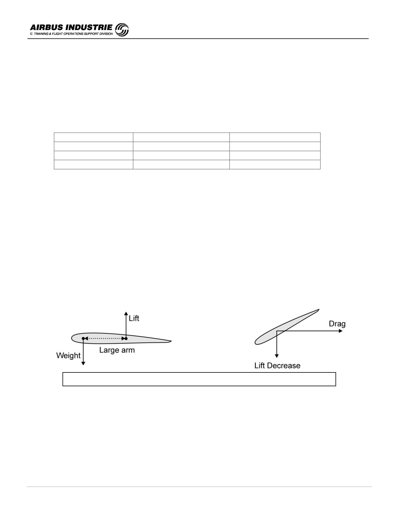
The weight and lift forces do create a pitching moment which is counteracted by the THS setting.
When the CG is located forward, the resulting pitching down moment is counteracted by a large THS nose down
setting which induces a lift decrease and a drag increase.
As a general rule, FWD CG penalizes the Performance
• At Take-off and landing, it affects:
* The Stall speeds: Typically on A330/A340, the stall speed increases by 1.5 kts when CG varies from 26% to
full forward CG. This affects take-off and landing speeds thus associated distances.
* The rotation maneuver: It is "heavier", thus longer at forward CG.
This affects the take-off distance. For example, on an A340 at 250 t, the TOD increases from 3165 m to
3241 m, when CG varies from 26% to full forward CG, which represents a 2.42% TOD increase (T/O, FLAP3,
PACK: OFF, ISA, ALT 0).
DATE: JAN 2001
Page 7
UDY0102
A320 INSTRUCTOR SUPPORT
NORMAL OPERATION
* The climb performance itself: For example, if a climb gradient of 5% is required (e.g. due to obstacles) in the
previous take-off conditions, the MTOW is reduced from 257.6 t down to 256.2 t when CG varies from 26% to
full forward CG.
This is why on A320 and A340 take-off performance charts are provided at forward CG (which in most cases is
penalizing) and at 26%; these last charts may be used provided the actual aircraft CG is at least 28%.
•
In cruise, an AFT CG minimizes the THS induced drag, thus improves fuel consumption. For example, the fuel
increase on a 1000 nm cruise segment is as follows, considering a heavy aircraft in high altitude and CG 20% or
35%:
A/C TYPE
FUEL BURN INCREASE
A320s
Negligeable
A330
220 kg
A340
380 kg
This explains why there is a trim tank system on A330/A340.
-
Handling Characteristics considerations
On fly by wire aircraft, in Direct Law, the handling characteristics of the aircraft are affected by the location of the
CG as a mechanically controlled aircraft:
•
Stability Issue - Aerodynamic Centre or Neutral Point
The aircraft is considered as stable, if in case of a perturbation or gust, the aircraft tends to react back towards its
previous status.
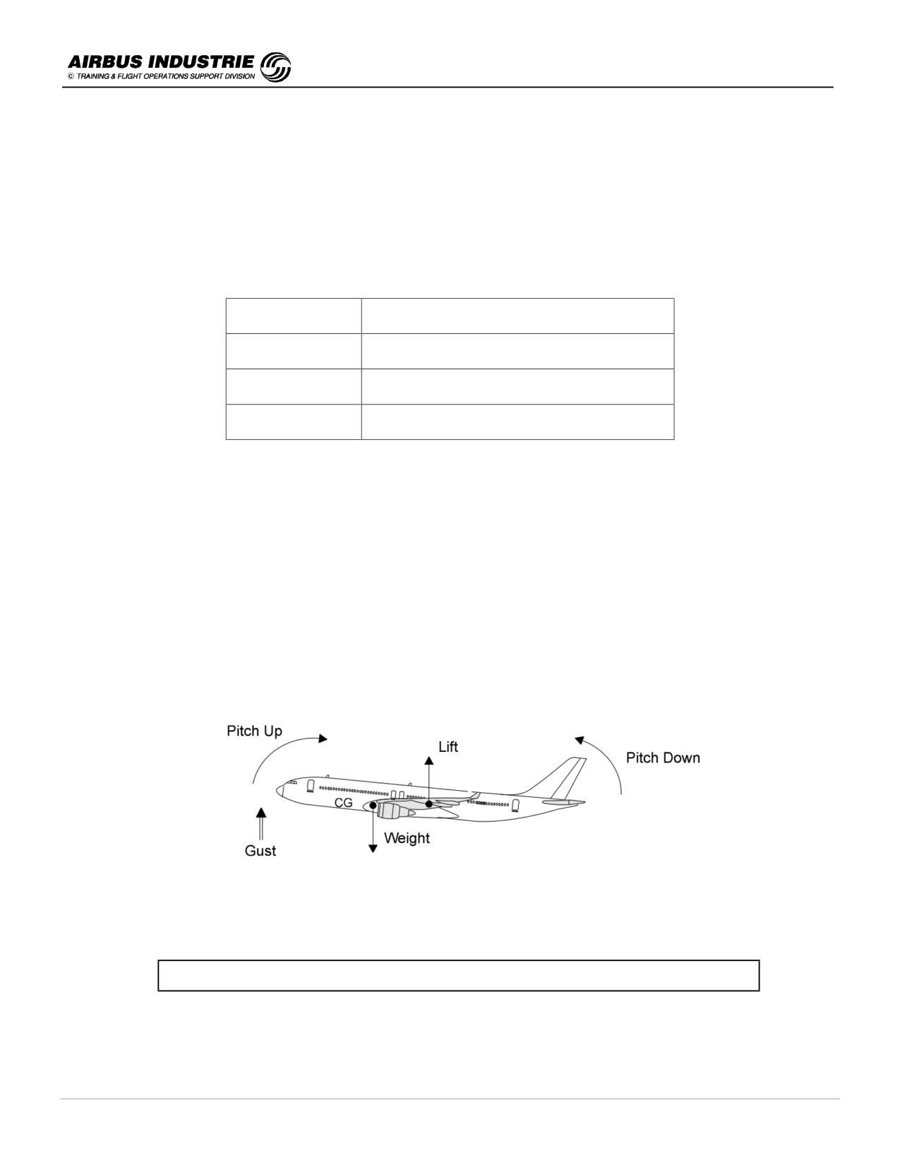
The aerodynamic centre, also called neutral point, is the location where an increase (or decrease) of lift is applied
when the aircraft angle of attack varies.
The hereabove gust causes an angle of attack increase, thus an additional lift; the aircraft is stable if the lift/weight
forces do create a pitch down moment resulting in a decrease of the angle of attack.
Aircraft is stable if CG is forward of Aerodynamic Centre or Neutral Point.
DATE: JAN 2001
Page 8
UDY0102
A320 INSTRUCTOR SUPPORT
NORMAL OPERATION
• Maneuvering criteria - Maneuver point
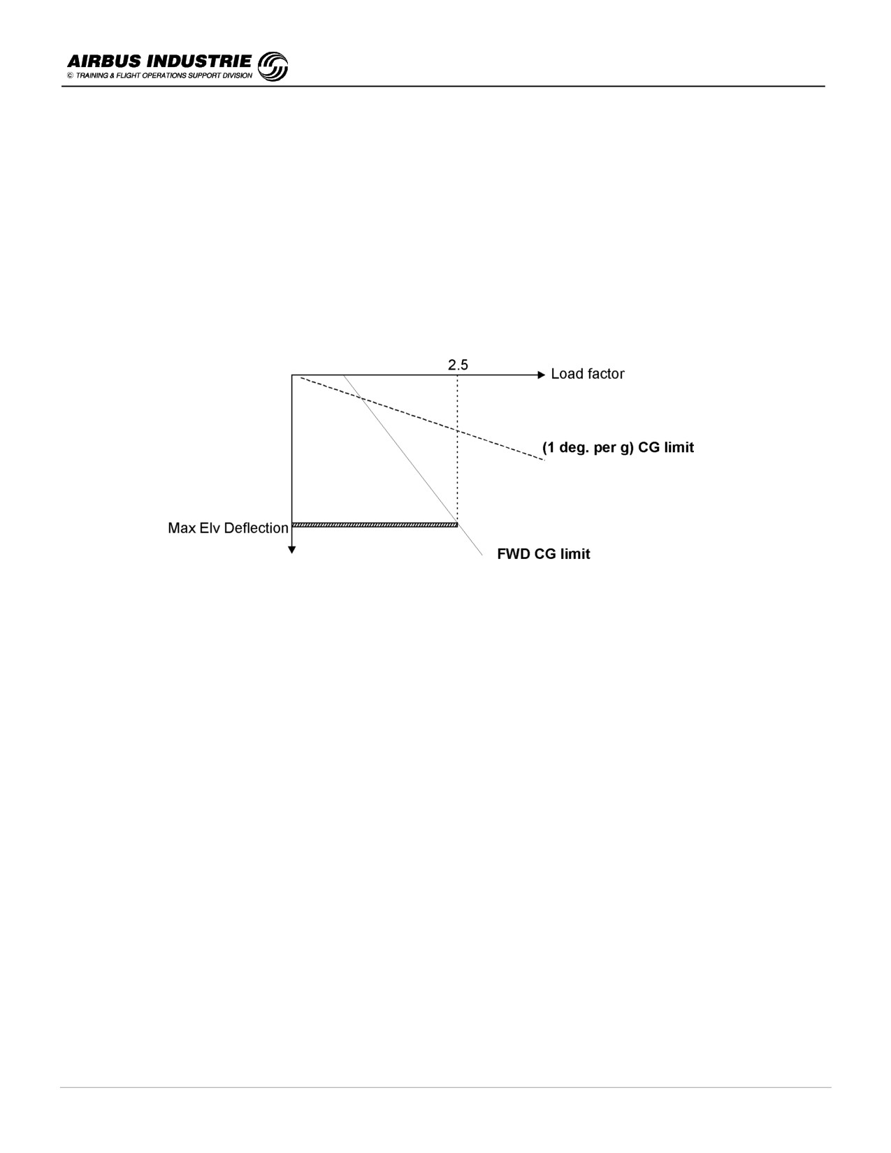
Depending upon the CG location, a given deflection of the elevator causes a more or less sharp aircraft maneuver.
In other words, the CG has a direct influence on the maneuverability of the aircraft.
If a very small deflection of the elevator causes "a lot of g", the efficiency of the elevator is very high; the aircraft is
considered as very touchy to maneuver.
The maneuver point is the location of the CG for which the efficiency of the elevator is infinite.
The CG must obviously be forward of the maneuver point by a lot. This lot is defined by a maneuverability criteria
which states that "at least 1° of elevator deflection is required to pull 1g load factor". This condition defines the
AFT CG limit maneuverwise.
But the CG must not be too far forward: indeed, the maximum elevator deflection must allow to pull at least the
maximum acceptable load factor (e.g. 2.5 g). This condition defines a FWD CG limit maneuverwise.
•
Ground handling characteristics
Essentially at high GW (thus at take-off), the CG is limited AFT so as to ensure enough Nose Gear adherence to
allow an efficient aircraft steering on the ground.
•
Take-off rotation characteristics
The CG must be limited so as to allow:
-
enough maneuverability during rotation
→ FWD CG limit.
-
enough margin versus potential tailstrike
→ AFT CG limit.
Obviously the THS is preset nose up in case of forward CG or nose down in case of AFT CG, in order to get
homogeneous aircraft rotation. But certification maneuvers require to demonstrate "abuse cases" such as taking-
off with FWD CG limit whileTHS is set nose down.
•
THS stall potential
-
in approach with flaps extended, there is a nose down moment counteracted by a THS nose up setting.
The more CG is forward, the more THS nose up setting is required. This may lead to a THS stall, more
particularly in cases of push over where the pilot pushes hard on the stick when he notices a significant speed
decrease.
This limits the FWD CG in approach.
-
in Go Around or Alpha Floor, the thrust increases to TOGA, more particularly at low speeds induces a
significant pitch up moment which increases when CG is more AFT. The elevator efficiency must allow to
counteract this pitch up moment, even at very low speed.
This limits the AFT CG in Go-Around and Alpha Floor.
DATE: JAN 2001
Page 9
UDY0102
A320 INSTRUCTOR SUPPORT
NORMAL OPERATION
• Structural Considerations
The CG cannot be too much forward due to Nose Gear structural limits; it cannot be too much AFT due to wing
and main landing gear strut limit.
• Loading Considerations
All the previous criterias allow to determine limits which, for example, would favor AFT CG configurations for
obvious performance efficiency.
However, the CG envelope must also take into account loading flexibility constraints.
• Passenger movement
The CG envelope must also allow passenger to move in the cabin.
This is the reason why once the take-off CG envelope has been determined, as well as the landing one (which is
less constraining), then the inflight envelope is defined usually providing at least a 2% margin with the previous
envelopes.
DATE: JAN 2001
Page 10
UDY0102