Airbus A330/A340. Flight Crew Training Manual (2007) - page 2
 

  Index      Manuals     Airbus A330/A340. Flight Crew Training Manual (2007)


Search            copyright infringement  


Content      ..      1      2      3      ..


Airbus A330/A340. Flight Crew Training Manual (2007) - page 2


FLIGHT CREW TRAINING MANUAL

OPERATIONAL PHILOSOPHY

FLIGHT CONTROLS

01.020

JAN 09/07

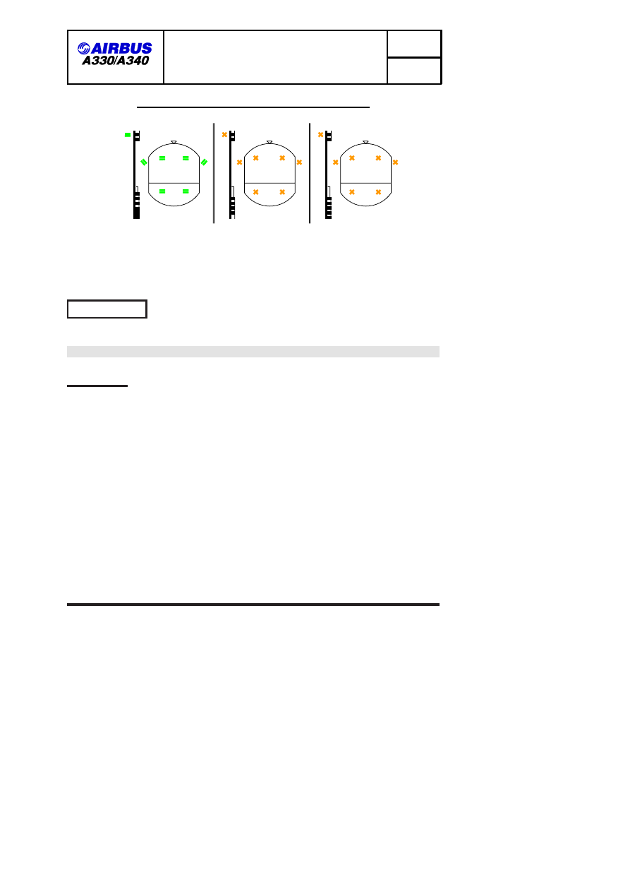
FLY-BY-WIRE STATUS AWARENESS VIA THE PFD

USE MAN PITCH TRIM

ALTN

NORMAL

DIRECT

FOF 01020 03762 0001

Therefore, by simply looking at this main instrument (PFD), the flight crew is

immediately aware of the status of flight controls, and the operational
consequences.

PROTECTIONS

R

MSN 0002-0860

OBJECTIVES

One of the PF’s primary tasks is to maintain the aircraft within the limits of the
normal flight envelope. However, some circumstances, due to extreme situations
or aircraft mishandling, may provoke the violation of these limits.

Despite system protections, the PF must not deliberately exceed the normal flight
envelope. In addition, these protections are not designed to be structural limit
protections (e.g. opposite rudder pedal inputs). Rather, they are designed to
assist the PF in emergency and stressful situations, where only instinctive and
rapid reactions will be effective.

Protections are intended to:

.

Provide full authority to the PF to consistently achieve the best possible

aircraft performance in extreme conditions

.

Reduce the risks of overcontrolling, or overstressing the aircraft

.

Provide PF with an instinctive and immediate procedure to ensure that the PF

achieves the best possible result.

ENV A330/A340 FLEET FCTM

Page 11 of 21

FLIGHT CREW TRAINING MANUAL

OPERATIONAL PHILOSOPHY

FLIGHT CONTROLS

01.020

JAN 09/07

BANK ANGLE PROTECTION

Bank angle protection prevents that any major upset, or PF mishandling, causes
the aircraft to be in a high-bank situation (wherein aircraft recovery is complex,
due to the difficulty to properly assess such a situation and readily react).

Bank

angle protection provides the PF with full authority to efficiently achieve any
required roll maneuver.

The maximum achievable bank angle is plus or minus:

.

67 degrees, within the Normal Flight envelope (2.5 g level flight)

.

45 degrees, in high AOA protection or high speed protection.

HIGH SPEED PROTECTION

When flying beyond maximum design speeds VD/MD (which are greater that
VMO/MMO), there is an increased potential for aircraft control difficulties and
structural concerns, due to high air loads. Therefore, the margin between
VMO/MMO and VD/MD must be such that any possible overshoot of the normal
flight envelope should not cause any major difficulty.

High speed protection adds a positive nose-up G demand to a sidestick order, in
order to protect the aircraft, in the event of a dive or vertical upset. As a result,
this enables a reduction in the margin betwen VMO/MMO and VD/MD.

Therefore, in a dive situation:

.

If there is no sidestick input on the sidestick, the aircraft will slightly overshoot

VMO/MMO and fly back towards the envelope.

.

If the sidestick is maintained full forward, the aircraft will significantly overshoot

VMO/MMO without reaching VD/MD. At approximately VMO + 16 / MMO +
0.04, the pitch nose-down authority smoothly reduces to zero (which does not
mean that the aircraft stabilizes at that speed).

AIRBUS HIGH SPEED PROTECTION

ENV A330/A340 FLEET FCTM

Page 12 of 21

FLIGHT CREW TRAINING MANUAL

OPERATIONAL PHILOSOPHY

FLIGHT CONTROLS

01.020

JAN 09/07

a)

360

320

340

360

320

340

360

320

340

HSP

activation

b)

360

320

340

340

360

380

a) stick free
b) stick full forward

High speed protection activation:

FOF 01020 03735 0001

The PF, therefore, has full authority to perform a high speed/steep dive escape
maneuver, when required, via a reflex action on the sidestick.

In addition, the

bank angle limit is reduced from 67 to 40 degrees, which minimizes the risk of a
spiral dive.

Note:

1. An OVERSPEED warning is provided.
2. At high altitude, this may result in activation of the angle of attack

protection.

LOAD FACTOR PROTECTION

On commercial aircraft, high load factors can be encountered during evasive
maneuvers due to potential collisions, or CFIT

Pulling "g" is efficient, if the resulting maneuver is really flown with this "g"
number.

If the aircraft is not able to fly this trajectory, or to perform this

maneuver, pulling "g" will be detrimental.

On commercial aircraft, the maximum load that is structurally allowed is:

.

2.5 g in clean configuration,

.

2.0 g with the flaps extended.

ENV A330/A340 FLEET FCTM

Page 13 of 21

FLIGHT CREW TRAINING MANUAL

OPERATIONAL PHILOSOPHY

FLIGHT CONTROLS

01.020

JAN 09/07

AIRBUS LOAD FACTOR PROTECTION AND SAFETY

2.5 g

Radius

2.5 g trajectory when
aircraft within proper flight domain.

FOF 01020 03736 0001

2.5 g pull
shallow trajectory when
aircraft out of proper
flight domain.

On most commercial aircraft, the potential for an efficient 2.5 g maneuver is very
remote. Furthermore, as G Load information is not continuously provided in the
cockpit, airline PFs are not used to controlling this parameter. This is further
evidenced by inflight experience, which reveals that:

In emergency situations,

initial PF reaction on a yoke or sidestick is hesitant, then aggressive.

With load factor protection, the PF may immediately and instinctively pull the
sidestick full aft: The aircraft will initially fly a 2.5 g maneuver without losing time.
Then, if the PF still needs to maintain the sidestick full aft stick, because the
danger still exists, then the high AOA protection will take over. Load factor
protection enhances this high AOA protection.

Load factor protection enables immediate PF reaction, without any risk of
overstressing the aircraft.

Flight experience has also revealed that an immediate 2.5 g reaction provides
larger obstacle clearance, than a hesitant and delayed high G Load maneuver
(two-second delay).

HIGH PITCH ATTITUDE PROTECTION

Excessive pitch attitudes, caused by upsets or inappropriate maneuvers, lead to
hazardous situations:

.

Too high a nose-up

u

Very rapid energy loss

.

Too low a nose-down

u

Very rapid energy gain

Furthermore, there is no emergency situation that requires flying at excessive
attitudes. For these reasons, pitch attitude protection limits pitch attitude to plus
30 degrees/minus 15 degrees.

Pitch attitude protection enhances high speed protection, high load factor
protection, and high AOA protection.

HIGH ANGLE-OF-ATTACK (AOA) PROTECTION

High AOA protection enables the PF to pull the sidestick full aft in dangerous
situations, and thus consistently achieve the best possible aircraft lift.

This

ENV A330/A340 FLEET FCTM

Page 14 of 21

FLIGHT CREW TRAINING MANUAL

OPERATIONAL PHILOSOPHY

FLIGHT CONTROLS

01.020

JAN 09/07

action on the sidestick is instinctive, and the high AOA protection minimizes the
risk of stalls or control loss.

High AOA protection is an aerodynamic protection:

.

The PF will notice if the normal flight envelope is exceeded for any reason,

because the autopitch trim will stop, the aircraft will sink to maintain its current
AOA (alpha PROT, strong static stability), and a significant change in aircraft
behavior will occur.

.

If the PF then pulls the sidestick full aft, a maximum AOA (approximately

corresponding to CL Max) is commanded. In addition, the speedbrakes will
automatically retract, if extended.

AIRBUS AOA PROTECTION

AOA

Prot Stick Neutral
THS stopped

Max Full aftstick

Floor − ATHR function

corresponding to

VLS Angle of attack

minimum allowed speed

VLS

V  Max

V  prot

CL

FOF 01020 03737 0001

In addition to this aerodynamic protection, there are three more energy features:

.

If ATHR is in SPEED mode, the speed cannot drop below VLS, even if the

target speed is below VLS

.

A "LOW ENERGY" aural alert triggers, when the aircraft energy level drops

below a specific threshold function of, for example, IAS, ACCEL/DECEL, or
FPA.
For example, if the aircraft decelerates at 1 kt/sec, and:
-- The FPA is -3 degrees, the alert will trigger at approximately VLS -8,

ENV A330/A340 FLEET FCTM

Page 15 of 21

FLIGHT CREW TRAINING MANUAL

OPERATIONAL PHILOSOPHY

FLIGHT CONTROLS

01.020

JAN 09/07

-- The FPA is -4 degrees, the alert will trigger at approximately VLS -2.
This "SPEED, SPEED, SPEED" alert draws the PF’s attention to the SPEED
scale, and indicates the need to adjust thrust.
It comes immediately before the ALPHA Floor, and is available when the
aircraft is below 2000 feet RA and is in CONF

2.

.

If the angle-of-attack still increases and reaches ALPHA Floor threshold, the

A/THR triggers TOGA thrust and engages (unless in some cases of one
engine-out).

In case of an emergency situation, such as Windshear or CFIT, the PF is
assisted in order to optimize aircraft performance via the:

.

A/THR:

Adds thrust to maintain the speed above VLS

.

Low Energy Speed

Speed warning: Enhances PF awareness

.

ALPHA FLOOR: Provides TOGA thrust

.

HIGH AOA protection: Provides maximum aerodynamic lift

.

Automatic speedbrake retraction: Minimizes drag.

Operational Recommendations:

When flying at alpha max, the PF can make gentle turns, if necessary.

The PF must not deliberately fly the aircraft in alpha protection, except for brief
periods, when maximum maneuvering speed is required.

If alpha protection is inadvertently entered, the PF must exit it as quickly as
possible, by easing the sidestick forward to reduce the angle-of-attack, while
simultaneously adding power (if alpha floor has not yet been activated, or has
been cancelled). If alpha floors has been triggered, it must be cancelled with the
disconnect pushbutton (on either thrust lever), as soon as a safe speed is
resumed.

In case of GPWS/SHEAR:

.

Set the thrust levers to TOGA

.

Pull the sidestick to full aft (For shear, fly the SRS, until full aft sidestick).

.

Initially maintain the wings level

This immediately provides maximum lift/maximum thrust/minimum drag. Therefore,
CFIT escape maneuvers will be much more efficient.

CFIT ESCAPE MANOEUVRES ON PROTECTED AND NON PROTECTED

AIRCRAFT

ENV A330/A340 FLEET FCTM

Page 16 of 21

FLIGHT CREW TRAINING MANUAL

OPERATIONAL PHILOSOPHY

FLIGHT CONTROLS

01.020

JAN 09/07

Initial a/c conditions:
Landing Conf.
VAPP
V/S − 1500ft/mn

ALT (ft)

200

100

−100

DIST (ft)

NON

INITIAL
ALTITUDE

PROTECTED

PROTECTED A/C

1000

GPWS PULL UP

Call out

1500

2000

2500

FOF 01020 03738 0001

The above-illustrated are typical trajectories flown by all protected or not
protected aircraft, when the PF applies the escape procedure after an aural "
GPWS PULL UP" alert.

The graph demonstrates the efficiency of the protection, to ensure a duck-under
that is 50 percent lower, a bucket-distance that is 50 percent shorter, a safety
margin that more than doubles (due to a quicker reaction time), and a significant
altitude gain (

±

250 ft).

These characteristics are common to all protected

aircraft, because the escape procedure is easy to achieve, and enables the PF
to fly the aircraft at a constant AOA, close to the max AOA.

It is much more

difficult to fly the stick shaker AOA on an aircraft that is not protected.

MECHANICAL BACKUP

MSN 0002-0370 0372-0375 0377-0382 0384-0390 0392-0393 0395-0409 0411-0415 0418-0425
0427-0430 0432-0435 0437-0439 0441-0444 0446-0448 0450-0452 0454-0456 0458-0459
0461-0463 0465-0467 0469-0470 0472-0474 0476-0477 0479-0481 0483-0484 0486-0487
0489-0491 0493-0494 0496-0498 0500-0513 0515-0516 0518-0519 0521-0522 0525-0530
0532 0535-0536 0538-0539 0541 0545-0546 0548 0550-0551 0554 0556 0559 0561-0562
0565 0567-0568 0581 0584 0597 0627 0635 0657 0660

The purpose of the

mechanical

backup is to achieve all safety objectives in

MMEL dispatch condition:

To manage a temporary and total electrical loss, the

temporary loss of five fly-by-wire computers, the loss of both elevators, or the
total loss of ailerons and spoilers.

ENV A330/A340 FLEET FCTM

Page 17 of 21

FLIGHT CREW TRAINING MANUAL

OPERATIONAL PHILOSOPHY

FLIGHT CONTROLS

01.020

JAN 09/07

It must be noted that it is very unlikely the

mechanical

backup will be used, due

to the fly-by-wire architecture. For example, in case of electrical emergency
configuration, or an all-engine flameout, alternate law remains available.

In the unlikely event of such a failure,

mechanical

backup enables the PF to

safely stabilize the aircraft, using the rudder and manual pitch trim, while
reconfiguring the systems.

In such cases, the objective is not to fly the aircraft accurately, but to maintain
the aircraft attitude safe and stabilized, in order to allow the restoration of lost
systems.

The pitch trim wheel is used to control pitch. Any action on the pitch trim wheel
should be applied smoothly, because the THS effect is significant due to its large
size.

The rudder provides lateral control, and induces a significant roll with a slight
delay. The PF should apply some rudder to turn, and wait for the aircraft reaction.
To stabilize and level the wings, anticipate by releasing the rudder pedals.

A red "MAN PITCH TRIM ONLY" message appears on the PFD to immediately
inform the PF that the mechanical backup is being used.

BACK-UP INDICATION ON PFD

MAN PITCH TRIM ONLY

FOF 01020 03740 0001

BACKUP

R

MSN 0371 0376 0383 0391 0394 0410 0416-0417 0426 0431 0436 0440 0445 0449 0453

0457 0460 0464 0468 0471 0475 0478 0482 0485 0488 0492 0495 0499 0514 0517 0520
0523-0524 0531 0533-0534 0537 0540 0542-0544 0547 0549 0552-0553 0555 0557-0558
0560 0563-0564 0566 0569-0580 0582-0583 0585-0595 0598-0626 0628-0634 0636-0656
0658-0659 0661-0860

ENV A330/A340 FLEET FCTM

Page 18 of 21

FLIGHT CREW TRAINING MANUAL

OPERATIONAL PHILOSOPHY

FLIGHT CONTROLS

01.020

JAN 09/07

The purpose of the backup is to achieve all safety objectives in MMEL dispatch
condition: To manage a temporary and total electrical loss, the temporary loss of
five fly-by-wire computers, the loss of both elevators, or the total loss of ailerons
and spoilers.

It must be noted that it is very unlikely the backup will be used, due to the
fly-by-wire architecture. For example, in case of electrical emergency
configuration, or an all-engine flameout, alternate law remains available.

In the unlikely event of such a failure, backup enables the PF to safely stabilize
the aircraft, using the rudder and manual pitch trim, while reconfiguring the
systems.

In such cases, the objective is not to fly the aircraft accurately, but to maintain
the aircraft attitude safe and stabilized, in order to allow the restoration of lost
systems.

The pitch trim wheel is used to control pitch. Any action on the pitch trim wheel
should be applied smoothly, because the THS effect is significant due to its large
size.

The rudder provides lateral control, and induces a significant roll with a slight
delay. The PF should apply some rudder to turn, and wait for the aircraft reaction.
To stabilize and level the wings, anticipate by releasing the rudder pedals.

A red "MAN PITCH TRIM ONLY" message appears on the PFD to immediately
inform the PF that the backup is being used.

BACK-UP INDICATION ON PFD

MAN PITCH TRIM ONLY

FOF 01020 03740 0001

ABNORMAL ATTITUDES

R

MSN 0002-0860

ENV A330/A340 FLEET FCTM

Page 19 of 21

FLIGHT CREW TRAINING MANUAL

OPERATIONAL PHILOSOPHY

FLIGHT CONTROLS

01.020

JAN 09/07

If the aircraft is, for any reason, far outside the normal flight envelope and
reaches an abnormal attitude, the normal controls are modified and provide the
PF with maximum efficiency in regaining normal attitudes. (An example of a
typical reason for being far outside the normal flight envelope would be a mid-air
collision).

The so-called "abnormal attitude" law is :

.

Pitch alternate with load factor protection (without autotrim)

.

Lateral direct law with yaw alternate

These laws trigger, when extreme values are reached:

.

Pitch (50 degrees up, 30 degrees down)

.

Bank (125 degrees)

.

AOA (30 degrees,

-10 degrees)

.

Speed (440 kt, 60 kt)

.

Mach (0.96, 0.1).

It is very unlikely that the aircraft will reach these attitudes, because fly-by-wire
provides protection to ensure rapid reaction far in advance.

This will minimize

the effect and potential for such aerodynamic upsets.

The effectiveness of fly-by-wire architecture, and the existence of control laws,
eliminate the need for upset recovery maneuvers to be trained on protected
Airbus aircraft.

SIDESTICK AND PRIORITY P/B

R

MSN 0002-0860

When the Pilot Flying (PF) makes an input on the sidestick, an order (an

electrical signal) is sent to the fly-by-wire computer. If the Pilot Not Flying (PNF)
also acts on the stick,

then both signals/orders are added.

Therefore, as on any other aircraft type, PF and PNF must not act on their
sidesticks at the same time. If the PNF (or Training Captain) needs to take over,
the PNF must press the sidestick priority pushbutton, and announce: "I have
control".

ENV A330/A340 FLEET FCTM

Page 20 of 21

FLIGHT CREW TRAINING MANUAL

OPERATIONAL PHILOSOPHY

FLIGHT CONTROLS

01.020

JAN 09/07

If a flight crewmember falls on a sidestick, or a mechanical failure leads to a
jammed stick (there is no associate ECAM caution), the "failed" sidestick order is
added to the "non failed" sidestick order.

In this case, the other not affected flight crewmember must press the sidestick
priority pushbutton for at least 40 seconds, in order to deactivate the "failed"
sidestick.

A pilot can at any time reactivate a deactivated stick by momentarily

pressing

the takeover push button on either stick.

In case of a "SIDE STICK FAULT" ECAM warning, due to an electrical failure,
the affected sidestick order (sent to the computer) is forced to zero. This
automatically deactivates the affected sidestick. This explains why there is no
procedure associated with that warning.

ENV A330/A340 FLEET FCTM

Page 21 of 21

FLIGHT CREW TRAINING MANUAL

OPERATIONAL PHILOSOPHY

AP / FD / ATHR

01.030

JAN 09/07

AUTOPILOT/FLIGHT DIRECTOR

R

MSN 0002-0860

R (1)

OBJECTIVE

The Auto Pilot (AP) and Flight Director (FD) assist the flight crew to fly the
aircraft within the normal flight envelope, in order to:

.

Optimize performance in the takeoff, go-around, climb, or descent phases

.

Follow ATC clearances (lateral or vertical)

.

Repeatedly fly and land the aircraft with very high accuracy in CAT II and

CAT III conditions.

To achieve these objectives:

.

The AP takes over routine tasks. This gives the Pilot Flying (PF) the

necessary time and resources to assess the overall operational situation.

.

The FD provides adequate attitude or flight path orders, and enables the PF

to accurately fly the aircraft manually.

MANAGED AND SELECTED MODES

The choice of mode is a strategic decision that is taken by the PF.

Managed

To fly along the

pre−planned F−PLN,

entered in the MCDU

For specific ATC requests,

or when there is not sufficient

time to modify the MCDU F−PLN

FOF 01030 00013 0001

Selected

Managed modes require:

.

Good FMS navigation accuracy (or GPS PRIMARY)

.

An appropriate ACTIVE F-PLN

(i.e. the intended lateral and vertical

trajectory is entered, and the sequencing of the F-PLN is monitored).

ENV A330/A340 FLEET FCTM

Page 1 of 18

FLIGHT CREW TRAINING MANUAL

OPERATIONAL PHILOSOPHY

AP / FD / ATHR

01.030

JAN 09/07

If these two conditions are not fulfilled

modes

selected

Revert to

FOF 01030 00014 0001

MAIN INTERFACES WITH THE AP/FD

MCDU

Long−term*

interface

To prepare lateral or vertical

revisions, or to preset the speed

for the next phase.

interface

FCU

Short−term

To

select

the ATC HDG,

expedite, speed, etc.

(quickly performed "head−up")

FOF 01030 00015 0001

*The DIR TO function is an exception to this rule.

Operational Recommendation:

With the FMS, anticipate flight plan updates by:

Preparing EN ROUTE

DIVERSIONS, DIVERSION TO ALTN, CIRCLING, LATE CHANGE OF RWY in
the SEC F-PLN.

This enables the MCDU to be used for short-term actions.

TASKSHARING AND COMMUNICATIONS

The FCU and MCDU must be used, in accordance with the rules outlined below,
in order to ensure:

.

Safe operation (correct entries made)

.

Effective inter-pilot communication (knowing each others intentions)

.

Comfortable operations (use "available hands", as appropriate)

ENV A330/A340 FLEET FCTM

Page 2 of 18

FLIGHT CREW TRAINING MANUAL

OPERATIONAL PHILOSOPHY

AP / FD / ATHR

01.030

JAN 09/07

MCDU entries

are performed by the

PF, during a temporary transfer of

command to the PNF.

A crosscheck must be performed.

Time−consuming entries should be

avoided below 10000 feet.

(PERF APPR, DIR TO, DIR TO

INTERCEPT, RAD NAV, LATE

CHANGE OF RUNWAY, ACTIVATE

SEC F−PLN, ENABLE ALTN)

FCU entries

are performed by:

− The PF, with the AP on.
− The PNF (upon PF request),

with the AP off.

FCU entries must be announced.

Upon FCU entries:

The PF must check and announce the

corresponding PFD/FMA target and

mode.

The PNF must crosscheck and

announce "CHECKED".

FOF 01030 00016 0001

Entries should be restricted to those

that have an operational benefit.

AP/FD MONITORING

The FMA indicates the status of the AP, FD, and A/THR, and their
corresponding operating modes. The PF must monitor the FMA, and announce
any FMA changes. The flight crew uses the FCU or MCDU to give orders to the
AP/FD. The aircraft is expected to fly in accordance with these orders.

The main concern for the flight crew should be:

WHAT IS THE AIRCRAFT EXPECTED TO FLY NOW ?

WHAT IS THE AIRCRAFT

EXPECTED TO FLY NEXT ?

If the aircraft does not fly as expected:

And, if in managed mode

Select

the desired target

FOF 01030 00017 0001

Or, disengage the AP, and fly the aircraft manually.

AUTOPILOT (AP) OPERATION

The AP can be engaged within the normal flight envelope, 5 seconds after liftoff
and at least 100 ft.

It automatically disengages, when the aircraft flies

significantly outside the normal flight envelope limits.

ENV A330/A340 FLEET FCTM

Page 3 of 18

FLIGHT CREW TRAINING MANUAL

OPERATIONAL PHILOSOPHY

AP / FD / ATHR

01.030

JAN 09/07

The AP cannot be engaged, when the aircraft is outside the flight envelope.
Flight control laws are designed to assist the flight crew to return within the flight
envelope, in accordance with the selected strategy.

The AP may be used:

.

For autoland: Down to the aircraft landing rollout, in accordance with the

limitations indicated in the FCOM

.

For other approaches, the minimum height is :

The MDA for straight in Non Precision Approach

MDA-100 ft for circling approach

160 ft for ILS approach with CAT1 displayed on

500 ft for all others phases.

It may also be used, in case of:

.

Engine failure: Without any restriction, within the demonstrated limits, including

for autoland

.

Abnormal configuration (e.g. slats/flaps failure): Down to 500 feet AGL. Extra

vigilance is required in these configurations. The flight crew must be ready to
take over, if the aircraft deviates from its intended, safe flight path.

The sidestick’s instinctive disconnect pushbutton should be used to disengage the
AP.

Instinctive override action on the sidestick consists of pushing or pulling the

sidestick, when the AP is engaged.

This action disengages the AP, and should

be done as per design, i.e. in case of an instinctive reaction (to an AP hard over
for example).

USE OF THE FD WITHOUT THE AP

When manually flying the aircraft with the FDs on, the FD bars or the FPD
symbol provide lateral and vertical orders, in accordance with the active modes
that the flight crew selects.

Therefore:

.

Fly with a centered FD or FPD

.

If not using FD orders, turn off the FD.

It is strongly recommended to turn off both FDs, to ensure that the A/THR is in
SPEED mode, if the A/THR is active.

AUTOTHRUST (A/THR)

ENV A330/A340 FLEET FCTM

Page 4 of 18

FLIGHT CREW TRAINING MANUAL

OPERATIONAL PHILOSOPHY

AP / FD / ATHR

01.030

JAN 09/07

R

MSN 0002-0860

OBJECTIVE

The A/THR computer (within the FG) interfaces directly with the engine computer,
referred to as

the FADEC.

The A/THR sends to the FADEC the thrust targets that are needed to:

.

Obtain and maintain a target speed, when in SPEED mode

.

Obtain a specific thrust setting (e.g. CLB, IDLE), when in THRUST mode.

INTERFACE

When the A/THR is active, the thrust lever position determines the maximum
thrust that the A/THR can command in SPEED or THRUST mode. Therefore,
with A/THR active, thrust levers act as a thrust limiter or a thrust-rating panel.

The A/THR computer does not drive back the thrust levers. The PF sets them to
a

specific detent on the thrust lever range.

The A/THR system provides cues

that indicate the energy of the aircraft:

.

Speed, acceleration, or deceleration, obtained by the speed trend vector

.

N1, and N1 command on the N1 gauge.

All these cues are in the flight crews direct line of vision.

In other words, the Thrust Lever Angle (TLA) should not be used to monitor
correct A/THR operation. Neither should the thrust lever position of a conventional
autothrottle, be considered a cue because, in many hazardous situations, the
thrust lever position can be misleading (e.g. engine failure, thrust lever jammed).

THE TLA DETERMINES MAX THRUST FOR THE A/THR

5

60.0

5

60.0

CLB

MCT

CLB

MCT

Thrust Lever

Angle

(TLA)

FOF 01030 00018 0001

TLA

ENV A330/A340 FLEET FCTM

Page 5 of 18


Content      ..      1      2      3      ..