Diesel WARTSILA F 240. Manual (2004) - page 2
Manual
F 240
AIR INLET AND EXHAUST SYSTEM
8A INTRODUCTION
Air cooler
The combustion air passes the turbocharger and flows into the air cooler. The air
(1.4)
cooler cools the combustion air to receiver temperature.
In the air cooler there is a slight pressure drop. After the air cooler the combustion air
flows via the air receiver into the cylinders.
The reduction of the combustion air temperature, (raising of the specific mass), has
a good effect on the efficiency of the engine and on the temperatures in the engine.
When the cooling water temperature in the air cooler is too low, the receiver
temperature drops too much, resulting in a not--optimal combustion.
Contamination of the air cooler, the air part or the water part, gives a reduction in
capacity of the air cooler. As a result, the receiver temperature rises.
Contamination of the air part of the cooler decreases the pressure in the receiver.
See the Sub--suppliers manuals for a detailed description of the air cooler.
Exhaust manifold
The exhaust manifold can expand in all directions. There are compensators between
(2.1)
the exhaust manifold and the turbocharger and in between the exhaust manifold of
each cylinder configuration.
All parts of the exhaust manifold are insulated and protected by a steel plate cover.
--o--o--o--o--o--
Ver. 01
8 -- 2
Manual
F 240
AIR INLET AND EXHAUST SYSTEM
8B COMBUSTION AIR REQUIREMENTS
1.
Specification
The combustion air must meet the following requirements:
-- it must be sufficient free of:
-- dust ;
-- fluid ;
-- chemical pollution.
-- maximum resistance of the inlet system before the
turbocharger(s)
20 mbar ;
-- maximum resistance of the exhaust system
directly after the turbocharger(s)
30 mbar ;
-- receiver temperature
max
60oC ;
-- maximum exhaust gas temperature after
the cylinder
450oC ;
Reference
-- Barometric pressure
1,0 bar ;
conditions
-- Inlet air temperature
min -- max
0oC--25oC ;
-- Relative humidity at 298 K
30% ;
-- Resistance of the inlet system before
the turbocharger(s)
max
10 mbar ;
-- Receiver temperature
50oC.
When the values of the reference conditions deviate, derate the output according to:
-- 0.4% peroC inlet air temperature above the maximum ;
-- 0.4% peroC receiver temperature above the maximum ;
-- 0.4% peroC inlet air temperature below the minimum ;
Attention!
When adjusted reference specifications are provided and any values deviate from that
reference specification, the maximum engine output should be reduced according to
the above values.
2.
Receiver pressure
Reduction of the pressure in the receiver can be caused by:
and exhaustgas
-- contamination of the compressor and the turbine of the turbocharger;
temperature
-- contamination of the air intake filter;
-- contamination of the air cooler ;
-- Receiver draining not set properly.
This causes a rise in exhaust gas temperatures and engine parts.
Thermal overload can occur:
-- if the receiver pressure drops ca. 0,2 bar lower than the value mentioned in the
test report. (maximum rpm and maximum setting of the H.P. fuel pumps);
-- and/or exceeding of the maximum exhaust gas temperature.
Reduce the load of the engine until the maximum exhaust temperatures are gained.
--o--o--o--o--o--
Ver. 01
8 -- 3
Manual
F 240
AIR INLET AND EXHAUST SYSTEM
8C CHARGE AIR CONDENSATION
Before starting work, consult:
-- chapter 2, ”BACKGROUND INFORMATION”.
Condensate is developed by cooling down of warm inlet air.
The condensate is constantly drained via two small discharges at the lowest points of
the air inlet housing.
1. Checking
When the engine is running under load, inlet air and condensate has to blow out of the
discharge
discharges.
opening
At a high air humidity it is normal that condensate flows constantly out of the discharge.
Check the discharge during ”normal” operation.
If no air blows out of the discharges this indicates that the discharges are blocked.
2. Inspection
Remove the discharges and check the connections of the air inlet casing and the
discharge
discharges for blockages.
When water still flows out of the discharges after the engine has been stopped, this
may point to a leaking air cooler element.
--o--o--o--o--o--
Ver. 01
8 -- 4
Manual
F 240
AIR INLET AND EXHAUST SYSTEM
8D TURBOCHARGER
Before starting work, please consult:
-- chapter 2, ”BACKGROUND INFORMATION” ;
-- part 3, ”SUB SUPPLIERS MANUALS”.
1. General
Even the slightest fouling can cause a rise in temperature of the charge air and/or drop
of the charge air pressure after the compressor.
2. Cleaning
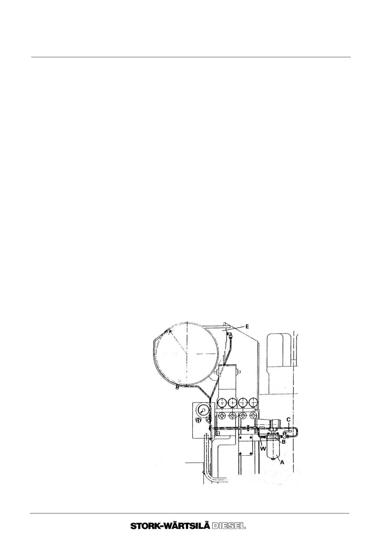
Cleaning has to be done by means of water injection, when the turbocharger is in oper-
compressor side
ation. The cleaning device is built on to the turbocharger. Cleaning may only be done
with fresh water.
For an effective cleaning it is necessary that the engine has been in operation for at
least 30 minutes and, if possible, at a minimum load of 80%. In other words, with the
highest possible speed of the turbocharger.
Attention!
-- It is only allowed to use clean water for cleaning the turbocharger ;
-- It is not allowed to use degreasing fluids, cleaning agents or other additives, be-
cause of inflammability, chemical attack on engine parts etc.
2. 1. Remove water injection tank A, fill it with fresh water and replace it again.
2. 2. Open valve C and all the water will be injected in about 5 seconds. Close the
valve when the tank is empty.
Ver. 01
8 -- 5
Manual
F 240
AIR INLET AND EXHAUST SYSTEM
8D TURBOCHARGER
3. Cleaning the air
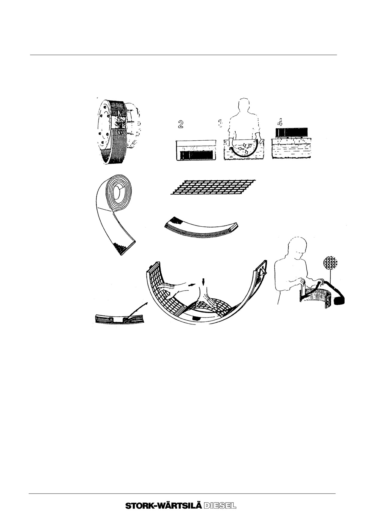
The filter must be cleaned from time to time. The frequence with which this must be
filter
done depends on the dust content of the suction air and the number of running hours
of the engine.
3. 1. The filter element can be removed by unscrewing the wing nuts and taking
off the cover.
3. 2. Before flushing the filter element in a hot soda solution or any other fat--dis-
solving liquid, any loose dirt should first be shaken off.
3. 3. The element must then be allowed to dry thoroughly, immersed in lubricating
oil and left to drain at room temperature for a period of 12 to 24 hours.
Note:
The filter may on no account be exposed to an open flame or great heat.
3. 4. To avoid suction of false air the wing nuts must be well tightened when reas-
sembling the filter.
3. 5. For a detailed information about other types of air filters, see the SUB
SUPPLIERS MANUALS.
--o--o--o--o--o--
Ver. 01
8 -- 6
Manual
F 240
AIR INLET AND EXHAUST SYSTEM
8E EXHAUST COMPENSATORS
Before starting work, please consult:
-- chapter 2, ”BACKGROUND INFORMATION”.
1. Necessary
Tool A.
tools
Dummy for the compensator. When replacing a compensator, a dummy is used for
aligning the exhaust pipe flanges.
Tool number 6104 F 457: 66562--001
Tool number 6104 F 459: 66562--004
2. Fitting of the
Practice has shown that a new compensator may rapidly become defective because
compensator
of misalignment of the connecting flanges causing the inner sleeve to vibrate against
the inside of the compensator, and cause the compensator to rupture.
This can be prevented by aligning the exhaust gas pipe with dummy A without gaskets.
Before a new compensator is installed the position of the exhaust flanges relative to
each other should be checked.
By calculating the length of the dummy, the pre--tension and the thickness of the
gaskets is acounted for. Make ssure that the two flanges are exactly parallel, and that
the bolt holes are in alignment.
2. 1. Make sure that the connecting flanges and the expansion joint are clean and
undamaged.
2. 2. Mind the direction of the gas flow.
Fit the exhaust compensator using two new gaskets.
Smear Molycolte, or another anti seize compound to the bolts.
2. 3. Tighten the nuts evenly and diagonally.
--o--o--o--o--o--
Ver. 01
8 -- 7
Manual
F 240
AIR INLET AND EXHAUST SYSTEM
8F GENERAL DIAGRAM
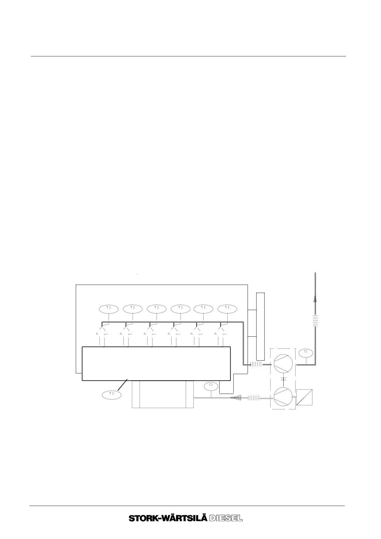
Explanation of the item numbers in the diagram.
1. Air inlet
No. Name
1. 1. Inlet air filter ;
1. 2. Turbocharger, (1.2.1 = Compressor and 1.2.2 = Turbine) ;
1. 3. Expansion compensator
1. 4. Air cooler ;
1. 5. Air receiver.
2. Exhaust gases
No. Name
2. 1. Exhaust manifold ;
2. 2. Expansion compensator (before and after turbine).
Explanation of
No. Name
letters
TI
Temperature indicator ;
TO EXHAUST GAS DAMPER
2.1
2.2
1.5
1.2.2
2.2
1.2
1.3
1.4
1.2.1
1.1
--o--o--o--o--o--
Ver. 01
8 -- 8
Manual
F 240
STARTING AND STOPPING SYSTEM
9A INTRODUCTION
3. General
The starting and stopping system consists of various components among which a
compressor and an air bottle. The compressed air is only used for the following engine
procedures:
-- starting the engine;
-- controlling the electric/pneumatic stopping device ;
-- controlling the pneumatic oil pump (3.1) for the valve seat lubricator ;
-- controlling the order--dependent measuring and regulating equipment.
Paragraph 9B is a description of the starting and stopping procedure. Depending on
the installation it is possible to implement one or more actions.
4. Description of
This section gives a general description of engine parts. The most important engine
engine parts
parts are presented in the schematic diagram, section 9D. The numbers between
brackets correspond to the numbers in the schematic diagram.
Starting device
The compressed air is only used for the above mentioned engine procedures and
(1.--)
should be free of water.
In case the compressor forms part of the Stork--Wärtsilä Diesel supply, consult the
Sub--suppliers manuals for details.
The starting air is supplied via a starting air valve (1.3), to be operated manually or/and
electrically, as starting air to the starting air valves (1.5), and as pilot air to the air
distributor (1.6).
Stopping device
The engine can be stopped either by remote control, by means of the
(2.--)
electric/pneumatic stopping device activated by the security system or manually by
pushing down a stopping lever until the engine stops.
In case of an engine failure, a stopping signal is given from the security and alarm
system. This stopping signal causes the magnetic three--way valve (2.2) to open and
the pilot air flows via the filter--water separator and the reducing valve to the stopping
cylinder (2.3).
The stopping cylinder pushes the regulating shaft (2.4) and the racks of the fuel pumps
to zero, which causes the engine to stop.
--o--o--o--o--o--
Ver. 01
9 -- 1
Manual
F 240
STARTING AND STOPPING SYSTEM
9B STARTING PROCEDURE
1.
Prior to Starting
Prior to starting the following preparations have to be made:
Fuel system
o Check the fuel level of the day tank. Fill up if necessary ;
o Check if the valves are in the correct position.
Cooling water
o Check the cooling water level of the cooling water tank. Fill up if necessary;
system
o Check if the valves are in the correct position.
Starting and
o Check that the starting air pressure is 30 bar, pressurise if necessary ;
stopping system
o Open the air bottle valve of the starting air (and control air) ;
o Check that the stopping air pressure is 6 bar.
Alarm system
o Switch on the alarm system ;
o Check the stopping device.
Lubricating oil
o Check the oil level of the engine. Fill up if necessary;
system
o Check the oil level in the turbocharger, in case of VTR--version. Fill up, if necessary
o Check the movability of all fuel racks. Grease with engine lubricating oil, if
necessary ;
o Start the pre--lubrication system;
o Open the decompression cocks if applied, or put the starting handle in
decompression position.
Bar the engine two turns;
o Close the decompression cocks if applied, or put the starting handle in neutral
position ;
o Stop the prelubrication system, when the oil pressure gauge indicates pressure
or a minimum of 5 minutes after starting of the prelubrication system.
Start the engine as quickly as possible after stopping the prelubrication.
Within 25 sec. if a VTC turbocharger is applied.
2.
Starting
o Starting by hand takes place by pushing the starting handle down ;
Operate the starting handle ;
o Stop operating the starting handle, as soon as combustion is heard ;
o Close the air supply to the starting handle ;
o Run the engine at low load until the oil temperature is minimal 50 oC. Then
increase the engine load uniformly to the desired load in about 20 minutes or
speed up the engine at nominal r.p.m. and load uniformly to the desired load in
about 20 minutes.
3.
Stopping
Before stopping, the engine has to run at no load during max. two to three minutes in
order to prevent the cylinder and piston temperatures from rising unnecessarily high
after stopping the engine.
o Switch off the alarm system ;
o Close the valve of the day tank if the engine is not to be operated within1 day.
--o--o--o--o--o--
Ver. 01
9 -- 2
Manual
F 240
STARTING AND STOPPING SYSTEM
9C STARTING AIR DISTRIBUTOR
Before starting work please, consult:
-- chapter 2, ” BACKGROUND INFORMATION”.
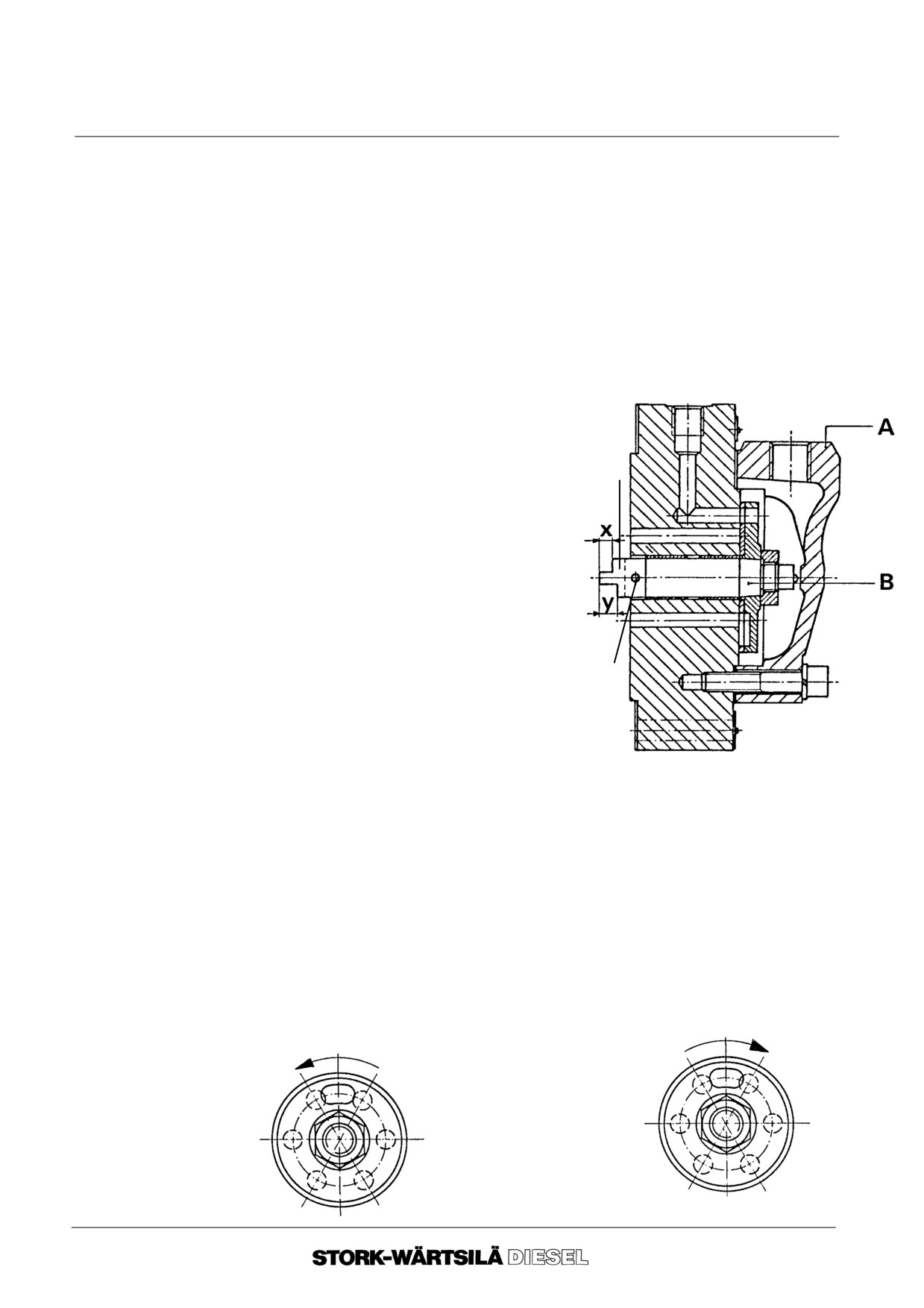
The air distributor disc takes care that pilot air flows to the starting valve of the cylinder
just starting its firing stroke.
The air distributor disk is driven by the camshaft by means of a distributor shaft, the
direction of rotation is the same as the direction of rotation of the engine.
1.
Replacing the
driver
1.
1.
Disconnect the air supply line E to the
cover of the starting air distributor.
1.
2.
Remove cover A and the gasket.
E
1.
3.
Pull the distributor shaft B, complete
with nut, distributor disc and driver,
D
out of the distributor housing.
1.
4.
Remove the dowel pin C from the
driver D and distributor shaft.
1.
5.
Fit the new driver with a new dowel
pin.
1.
6.
Place the distributor shaft, complete
with nut, distributor disc and driver,
into the distributor housing.
C
Attention!
There should be no clearance
between the distributor disc and the
distributor housing. If there is any
clearance, turn the complete
distributor shaft 180 .
The driver recesses “x” and “y” have
different lengths.
2.
Checking the
setting
Turn the flywheel to 5
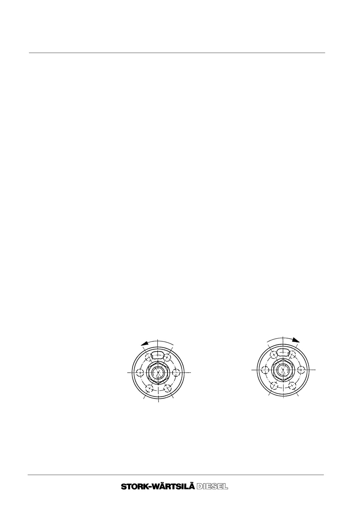
past top dead centre of e.g. cylinder 1. The first part of the slot
in the distributor disc should be 1/3 open to the air passage to cylinder 1 in the
distributor housing. Mind the direction of rotation!
If the setting is not correct see point 3.
Example of a 6 cylinder engine.
Ver. 01
9 -- 3
Manual
F 240
STARTING AND STOPPING SYSTEM
9C STARTING AIR DISTRIBUTOR
2.
1.
Fit the cover, using a new gasket.
2.
2.
Connect the air supply line to the cover of the starting air distributor.
3.
Setting the
distributor disc
3.
1.
Turn the flywheel to 5
past the top dead centre of e.g. cylinder 1.
3.
2.
Unscrew the air supply line to the cover of the starting air distributor.
3.
3.
Remove the cover and gasket.
3.
4.
Pull the distributor shaft, complete with nut, distributor disc and driver, out of
the distributor housing.
3.
5.
Loosen the nut by a few turns.
Pay attention to the type of thread, in connection with the direction of
rotation.
Look at the final digit on the rating plate of the starting air distributor.
1 = left--hand thread
2 = right--hand thread
3.
6.
Tap the end of the distributor shaft with a plastic hammer to separate the
distributor disc from the conical part.
3.
7.
Tighten the nut manually, but not too tightly, so that the distributor disc can
still turn on the shaft.
3.
8.
Place the distributor shaft, complete with nut, distributor disc and driver, into
the distributor housing.
There should be no clearance between the distributor disc and the
distributor housing.
If there is any clearance, turn the complete distributor shaft 180 .
3.
9.
Set the distributor disc so that the first part of the slot in the distributor disc is
1/3 open to the air passage to cylinder 1 in the distributor housing.
Pay attention to the direction of rotation!
Example of a 6 cylinder engine.
3. 10.Tighten the nut without turning the distributor disc.
3. 11. Fit the cover with a new gasket.
3. 12.Fit the air supply line to the cover of the starting air distributor.
--o--o--o--o--o--
Ver. 01
9 -- 4
Manual
F 240
STARTING AND STOPPING SYSTEM
9D GENERAL DIAGRAM
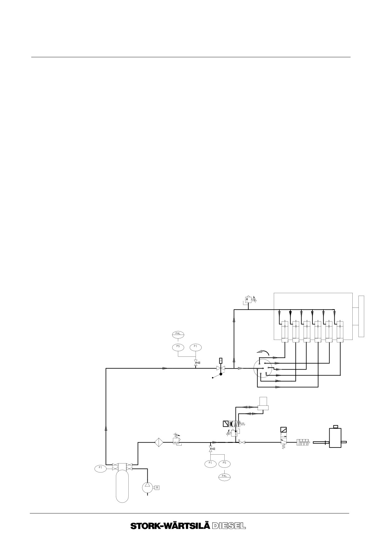
Explanation of the numbers in the diagram, of a 6 cylinder clockwise turning engine for
operation on MDO. The pipelines between the engine parts 1.2 to 1.5 are for starting air,
the other pipelines are for pilot air.
1.
Starting system
No.
Name
1.
1.
Air compressor
1.
2.
Air bottle
1.
3.
Starting air intermediate valve, (manual and/or electrically
controlled)
1.
4.
Safety valve
1.
5.
Starting valve (per cylinder)
1.
6.
Air distributor
2.
Stopping device
2.
1.
Non return valve
2.
2.
Electric/pneumatic three--way valve (for overspeed security)
2.
3.
Stopping cylinder
2.
4.
Fuel control shaft
3.
Pneumatic pump
3.
1.
Pneumatic pump
3.
2.
Electric/pneumatic four--way valve
3.
3.
Reducing valve
4.
Miscellaneous
4.
1.
Needle valve
4.
2.
Filter/water seperator
4.
3.
Reducing valve
Explanation
PAL
Pressure alarm Low
letters
PI
Pressure indicator
PS
Pressure switch
1.4
1.5
1
2
3
4
5
6
4.1
1.6
1.3
3.1
3.2
2.2
3.3
4.2
2.3
2.4
4.1
2.1
4.3
1.2
1.1
--o--o--o--o--o--
Ver. 01
9 -- 5
Manual
F 240
STARTING AND STOPPING SYSTEM
9D GENERAL DIAGRAM
Ver. 01
9 -- 6
Manual
F 240
ALARM AND SAFETY SYSTEM
10A DESCRIPTIONS
5. General
The engine is provided with equipment for protection against several kinds of faults.
The engine protection system is divided into:
-- speed transmitter ;
-- alarm and protection switches ;
-- alarm and protection unit
optional delivery ;
-- co--signaling board
optional delivery.
For a general description see points 2 to 5 of this section.
The alarm and protection system can be delivered, suitable for flush mounting, for wall
mounting or in a switch board.
Depending on the performance and application of the engine, either (stationary)
generator duty or propulsion, the speed governor is provided with and controlled by
an electric speed adjusting motor or a pneumatic speed adjusting cylinder for remote
control. At any load, the engine speed which was adjusted by the speed governor, can
be changed remotely with this motor or cylinder.
The electric speed adjusting motor is also of importance when a number of engines
are working in parallel on one electrical system. In this case, it is necessary to
synchronize the speed of the engine to be switched in, before switching on the circuit
breaker.
With the electric speed adjusting motor it is also possible to correct the load distribution
over the engines. If necessary, this can be done while they are working in parallel.
For information about the engine speed governor see the SUB--SUPPLIERS
MANUALS.
6.
Speed
To achieve the necessary signals and speed dependent switch functions, the engine
measuring
is provided with an electronic speed transmitter with an electro--magnetic speed
system
sensor.
See section 10C for the diagram, in the standard design, comprising the following
components:
6. 1. Electro--magnetic speed sensor (B):
An electro--magnetic speed sensor directed of the teeth of the camshaft--
gearwheel, provides the signal for the speed transmitter.
This sensor provides a frequency signal to the speed transmitter, equal to the
number of teeth of the camshaft gearwheel passing every second.
6. 2. Supply card (E1):
The speed transmitter is provided with a supply card, which takes care of the
necessary stabilised voltages for the other components of the system.
The required input voltage for this card itself is standard 24 volt DC (min. 20 and
max. 32 volt, including eventual ripples)
6. 3. Key--switch (2):
In order to be able to test the proper functioning of the overspeed protection the
speed transmitter is provided with a key switch with two positions:
--
“normal”, the standard overspeed protection functions as adjusted will trip
the engine at an actual speed of 1.15 times the rated speed ;
--
“test”, In the case of an engine in operation the increase of engine speed is
simulated and the overspeed relay will be actuated at approx. 60% of the rated
speed.
Ver. 01
10 -- 1
Manual
F 240
ALARM AND SAFETY SYSTEM
10A DESCRIPTIONS
6.
4.
Converter / overspeed card
(E3)
This card has two functions:
-- the converting part:
Converts the frequency signal of the electro--magnetic speed sensor in to a DC
voltage signal for the overspeed part and the separate speed dependant
switch functions.
This DC voltage signal is directly proportional to the number of rotations of the
engine. The relation between the input frequency signal of the speed sensor
and the output DC voltage signal of the converter can be adjusted by means
of a potentiometer, located on the card.
-- the overspeed part:
This part receives the output DC voltage signal of the converter part and is
provided with a voltage dependant relay, to stop the engine in case of
overspeed. The voltage, on which this relay switches, can be adjusted by
means of a second potentiometer, also located on this card.
When the voltage from the converter exceeds the set value, the relay will be
actuated, and this activates the shut down system of the engine by means of
its contact. The overspeed protection for the engine is set as standard to 1.15
times the nominal speed of the engine which means that the adjustment of the
overspeed relay can be determined, independent from the type of engine.
Note !
The adjustments of the converter card and the overspeed card are calibrated by
Stork--Wärtsilä Diesel with special equipment. Since the complete protection of
the engine depends on this adjustment, other people are not allowed to change
these adjustments. This is also the case for the cards (E4) and (E5).
The other cards are adjusted depending on their function, (for instance the delay
time for a stopping signal).
6.
5.
Alarm system on card
(E4):
With this speed switch card the alarm system of the engine can be switched on
and off. The working of this card is identical to the description of the overspeed
part of the earlier mentioned converter/overspeed card and is adjusted to switch
at 250 r.p.m. as standard When the engine can be remotely started, this card also
has the function of switching off the start command above 250 r.p.m.
6.
6.
Switch--on card for lubricating oil pressure alarm above 500 rpm (E5):
This card, which is only supplied for engines with variable speed, such as
propulsion engines, switches on the 2nd pressure switch for the low lubricating
oil pressure alarm above 500 r.p.m. and inhibits this switch below this speed. The
working of the card is identical to the working of the overspeed part of the
converter/overspeed card, and is adjusted, so that it switches at 500 r.p.m. as
standard
The alarm at low lubricating oil pressure is, with regards to the characteristic of
the engine driven lubricating oil pump, divided into two parts. Namely one below
and one above 500 r.p.m. Engines with variable speed are therefore provided
with two pressure switches for alarm at low lubricating pressure. One of these
switches is adjusted to a certain value for the speed area below 500 r.p.m., and
the other one to a higher value for the speed area above 500 r.p.m.
Ver. 01
10 -- 2
Manual
F 240
ALARM AND SAFETY SYSTEM
10A DESCRIPTIONS
6.
7. Wire break monitoring card for the stopping device
(E6):
This provision is only supplied when it is specially required by the applicable
classification society, and must be seen as an optional extra. In order to monitor
wire breaks in the shutdown system, a special card is built in. By means of this
card the electric circuit between the plus (+) of the supply voltage, the wiring and
the coil of the shutdown system to the minus (--) of the supply voltage, can be
monitored. For this purpose, a very low current flows via the earlier mentioned
circuit. This current is not capable of activating the shutdown system, but is
capable of activating the relay on the wire break monitoring card.
When the circuit is broken, by a lack of supply voltage, wire break or the burning
out of the shutdown solenoid, the relay will be de--actuated and give alarm.
6.
8. Speed indicator
(7):
The speed indicator, which indicates the speed of the engine, is in fact a moving
coil instrument with a range of 0--6 volt DC, provided with a scale of 0--1200 r.p.m.
6.
9. Reset button
(8):
With this push button, and signal light, the overspeed trip can be reset and/or
signaled. When the overspeed protection is activated, the overspeed relay is
locked, which means that it cannot be de--actuated, as a consequence the lower
entry--voltage of the relay, caused by the reducing speed of the stopping engine.
To be able to start the engine again, the reset button must be pushed to remove
this lock. With the signal light, the stopping of the engine (as a consequence of
overspeed) can be signaled visually.
6.
10.Running hours counter
(9):
The running hours counter is fed by the supply voltage of the system, and is
switched in by the speed switch card which also switches on the alarm system.
7. Alarm and
In order to prevent damage to the engine, as a consequence of a fault in a vital system,
protection
such as the cooling water, lubricating oil and shut down system, these are provided
switches
with alarm and protection switches.
In case of a dangerous deviation from the normal operating conditions (pressure
and/or temperature) in the relevant system, these switches give a signal to an alarm
and protection system, situated in another location (e.g. in a switchboard or an
operation desk).
When it concerns one or more stop switches, this system will also give a stopping
command to the electric/pneumatic stopping system, which belongs to the standard
equipment of the engine.
For the alarm and protection switches and the settings see the terminal diagram.
Ver. 01
10 -- 3
Manual
F 240
ALARM AND SAFETY SYSTEM
10A DESCRIPTIONS
8. Alarm and
The alarm and protection units display the alarm and protection signals of the engine.
protection unit
See section 10D for the diagram, in the standard design, comprising of the following
components:
8. 1. Supply card
(1.1):
The supply voltage can be signaled with an illuminated push button -- SUPPLY
ON/LAMP TEST -- with a blue lens; with this push button all signal lamps in the
system can be tested.
In order to silence the audible warning, the system is provided with an illuminated
push button -- KLAXON RESET -- with a yellow lens, which remains as on long
as the audible alarm is given.
In order to cancel the visual alarm, the system is provided with an illuminated
push button -- ALARM RESET -- with an orange lens.
When this push button is operated, while the fault has not yet been removed, the
flashing of the signal--light for the fault disturbance changes into a continuous
signal, however, the illuminated push button will remain flashing until the fault has
been removed.
After the fault has been removed, the flashing signal--light of the illuminated push
button as well as the continuously lit signal--light for the relevant fault will switch
off.
In case the fault has already been removed before the illuminated push button
could be operated, the flashing frequency of the relevant fault--light will only be
half the normal value.
In the case of faults, which cause the engine to be stopped, the shutdown
command is locked by the system. To be able to release this lock, the system is
provided with an illuminated push button -- STOP RESET -- with a red lens, the
signal light of which stays on as long as the stopping command is not removed.
8. 2. Delay card
(1.2):
Directly after the engine is started, the lubricating oil pressure will be insufficient
due to the fact that the pump is driven by the engine. To avoid this causing an
alarm and shutdown command, a delay in the system is built in, with which the
signal of the relevant switches (such as pressure and flow) is inhibited, until the
pressure of the lubricating oil has a sufficient value.
When this inhibit is released, and the system is completely on stand--by, this is
signaled by a signal light -- ALARM SYSTEM ON -- with a green lens.
Ver. 01
10 -- 4
Manual
F 240
ALARM AND SAFETY SYSTEM
10A DESCRIPTIONS
8. 3. Alarm cards
(1.3):
Signal indicators, for alarm only, are equipped with illuminated push buttons with
orange lenses.
The signal indicators, which also have a shut--down function, and the illuminated
push buttons are provided with red lenses.
By means of the push button element of the illuminated push button, each alarm
and protection function can be tested separately.
8. 4. Signal light / klaxon
(1.5 / 1.4):
When a fault takes place, the visual warning is given by the flashing of the
relevant signal light. The audible warning is given by a separate klaxon (1.4),
which can be connected to the system.
9. Co--signaling
In order to co--signal the engine alarm and protection unit, an additional board can be
board
supplied suitable to be built in to a desk. See general diagram section 10D.
The co--signaling board is provided with a speed indicator that is connected with the
0--6 V signal of card (E3).
Each illuminated push button is connected to the alarm and protection unit and follows
the signal of the alarm and protection unit.
The illuminated push button ”SIGNAL TEST / ALARM IN” signals the working of the
alarm and protection unit. All illuminated push buttons can be checked by means of
operating the button.
The illumination of push button ”SIGNAL TEST / ALARM IN” and the speed indicator
can be regulated by means of a dimmer (2.4).
When there is an alarm the corresponding signal indicator, the buzzer and the
illuminated push button indicator (”RESET BUZZER”) are switched on. The buzzer
and the signal indicator will be switched off as soon as the push button is pressed.
--o--o--o--o--o--
Ver. 01
10 -- 5
Manual
F 240
ALARM AND SAFETY SYSTEM
10B TESTING THE SETTINGS
1. General
The settings of the alarm and trip switches on the engine and of the printed circuit
boards in the electronic speed transmitter are given in the test report and the electrical
drawings delivered with the engines.
2.
Tests, Checks
In order to protect components on the cards against static electricity, avoid contacting
Calibrations
them with insufficiently grounded tools/objects.
2.
1.
Checking the availability of the alarm and safety system:
If the stand by lamp (usually green) is on, the alarm and safety system are
available.
2.
2.
Checking the overspeed trip and shut down device:
Stopped engine:
Put the key in “TEST” position and press “RESET” button. This should actuate
the shut down system and light the red lamp.
Restore the key to “NORMAL” and press “RESET” button.
Running engine:
Run the engine at approx. 65% r.p.m. Put the key in “TEST” position this should
actuate the shut down system.
Restore the key to “NORMAL” and press “RESET” button.
2.
3.
Checking the switching of the alarm and trip switches:
In order to avoid false alarms certain alarm and trip switches are only activated
at certain engine speeds (usually 250 r.p.m.). It is possible now to check that the
red LED on printed circuit board E4 (inside the electronic speed transmitter) lights
up when increasing over the set speed.
2.
4.
Checking the change--over to low pressure lubricating oil alarm at high
speed.(variable speed engines only):
Two switches are mounted for alarm at the loss of or decrease in lubricating oil
pressure. One at high and the other at low speed. The change over is usually
effected at 500 r.p.m. Check the test report for the correct value.The switch for
the high speed is inhibited below the set speed.
It is possible to check now that the red LED on printed circuit board E5 (inside
the electronic speed transmitter) lights up when increasing over the set speed.
Ver. 01
10 -- 6
Manual
F 240
ALARM AND SAFETY SYSTEM
10B TESTING THE SETTINGS
2. 5. Checking the operation of cards, alarm, delay and stop functions:
All alarm and trip switches should be checked by hand operation when the engine
is running. If the switches operate correctly the corresponding signal will appear
on the alarm and safety system and the engine will be tripped if applicable.
When checking the lubricating oil pressure alarm and trip on variable speed
engines the tests must be carried out at two different speeds.
2. 6. Temperature and pressure switch calibration:
All temperatures -- and pressure switches can be tested by symulating the
temperature and/or pressure.
And can be checked if the micro switch switches at the set value (see test report).
If necessary, reset the transmitters.
Note!
Temperature switches should always be tested when the temperature is rising
and pressure switches when the pressure is falling.
For possible exceptions see test report or electrical circuit diagram.
--o--o--o--o--o--
Ver. 01
10 -- 7
Manual
F 240
ALARM AND SAFETY SYSTEM
10C DIAGRAM RPM MEASURING SYSTEM
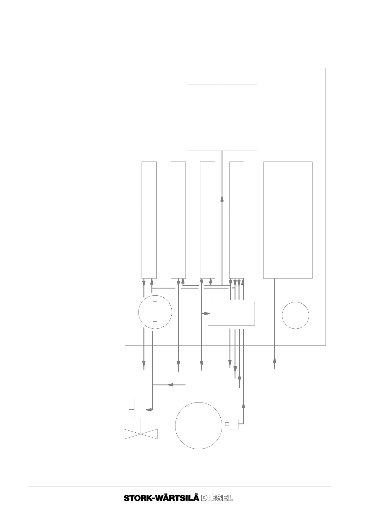
Explanation of the item numbers in the diagram.
Key to numbers
No.
Description
E1.
Supply circuit:
1. 1.Supply voltage.
2.
Key switch
E3.
Converter/over speed printed circuit:
3. 1. Rpm input signal.
3. 2. Overspeed alarm signal ;
3. 3. Overspeed stopping signal ;
3. 4. Converted rpm signal.
E4.
Switching printed circuit for alarm:
4. 1. Engine speed > 250 rpm.
E5.
Switching printed circuit for lubricating oil pressure alarm
high speed ( only on propulsion engines ):
5. 1. Engine speed signal > 500 rpm.
E6.
Wire break printed circuit:
6. 1. Alarm signal wire break stopping air solenoid valve.
7.
Rpm indicator ;
8.
Reset button ;
9.
Running hours counter.
Key to letters
No. Description
A Camshaft gear wheel ;
B Impulse pick--up ;
C Stopping air solenoid valve ;
D External stopping signals.
*
No standard delivery Stork--Wärtsilä Diesel.
Ver. 01
10 -- 8
Manual
F 240
ALARM AND SAFETY SYSTEM
10C DIAGRAM RPM MEASURING SYSTEM
Schematic
diagram
7
E6
E5
E4
E3
E1
2
9
8
6.1
5.1
4.1
3.4
1.1
3.3
D
3.2
A
C
B
3.1
--o--o--o--o--o--
Ver. 01
10 -- 9
Manual
F 240
ALARM AND SAFETY SYSTEM
10D DIAGRAM ALARM AND SAFETY
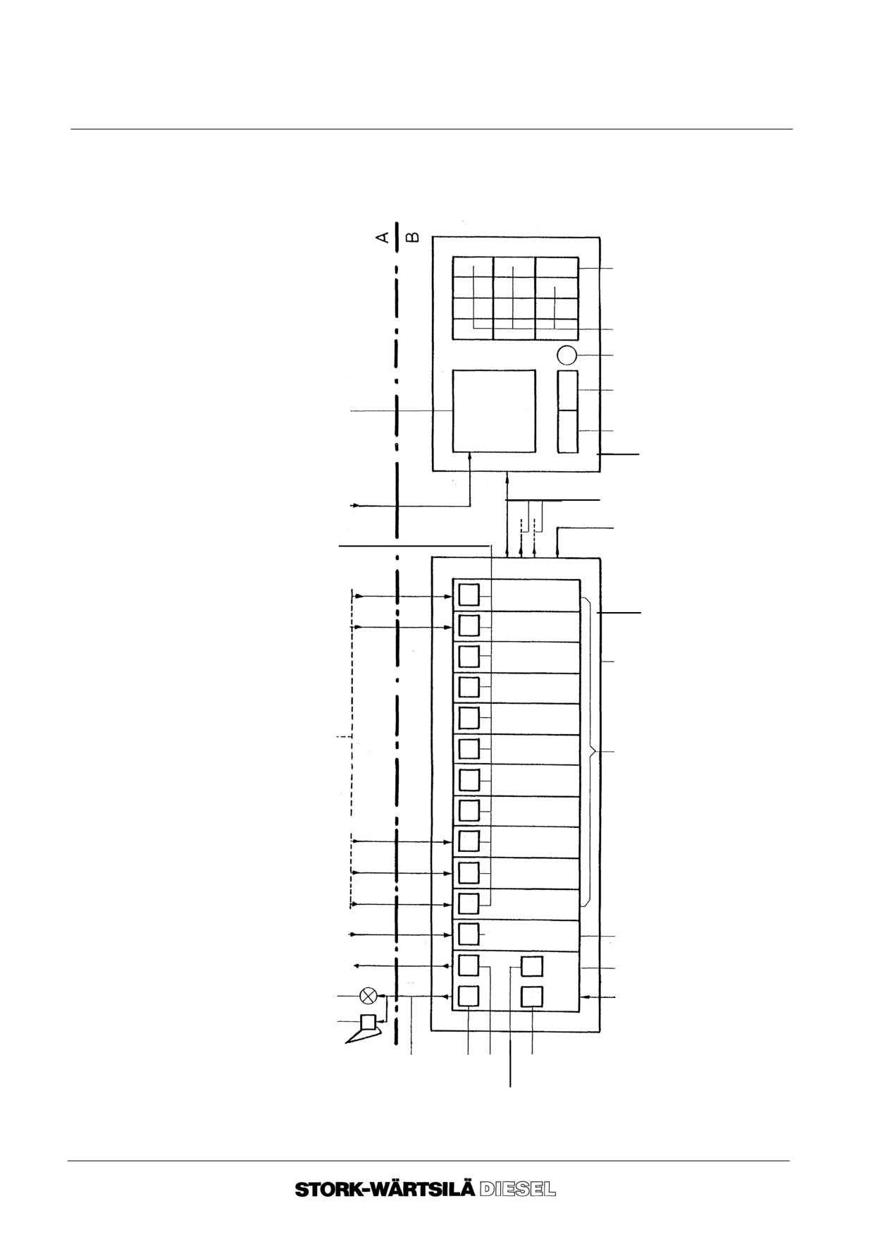
Explanation of components in the schematic diagram ALARM AND SAFETY SYSTEM
and Co--signaling tableau, (see next page).
1.
Alarm and safety
No.
Description
system
1.
1.
Mains supply printed circuit:
1.1.1
Supply voltage ;
1.1.2
General alarm signal;
1.1.3
Stopping signal;
1.1.4
Press button/indicator lamp klaxon reset ;
1.1.5
Press button/indicator lamp supply in/lamp test ;
1.1.6
Press button/indicator lamp stop reset ;
1.1.7
Press button/indicator lamp alarm reset.
1.
2.
System delay card:
1.2.1
Signal number of engine revolutions > 250 rpm ;
1.2.2
Indicator lamp alarm.
1.
3.
Alarm cards :
1.3.1
Signals of alarm and safety switches ;
1.3.2
Press button/indicator lamp alarm test/alarm ;
1.3.3
Signals for co--signaling.
1.
4.
Klaxon ;
1.
5.
Rotating flash light ;
1.
6.
Contacts for remote--signalling and control.
2.
Co--signaling
No.
Description
tableau
2.
1.
Rpm indicator:
2.1.1 Speed signal.
2.
2.
Press button/indicator lamp buzzer reset ;
2.
3.
Press button/indicator lamp test/alarm in ;
2.
4.
Dimmer ;
2.
5.
Indicator lamp for co--signalling ;
2.
6.
Indicator lamp engine stopped.
Key to letters
No.
Description
A
Engine and installation.
B
Electronic measuring system.
Ver. 01
10 -- 10
Manual
F 240
ALARM AND SAFETY SYSTEM
10D DIAGRAM ALARM AND SAFETY
Schematic
diagram
2.6
2.5
2.4
2.3
2.1
2.2
2
2.1.1
1.3.3
1.6
1.3.2
1
1.3
1.2.1
1.2.2
1.2
1.1.3
1.1
1.5
1.1.1
1.4
1.1.5
1.1.7
1.1.2
1.1.4
1.1.6
--o--o--o--o--o--
Ver. 01
10 -- 11
Manual
F 240
ALARM AND SAFETY SYSTEM
10D DIAGRAM ALARM AND SAFETY
Ver. 01
10 -- 12
Manual
F 240
MAIN BEARINGS
11A NECESSARY TOOLS
Tool A
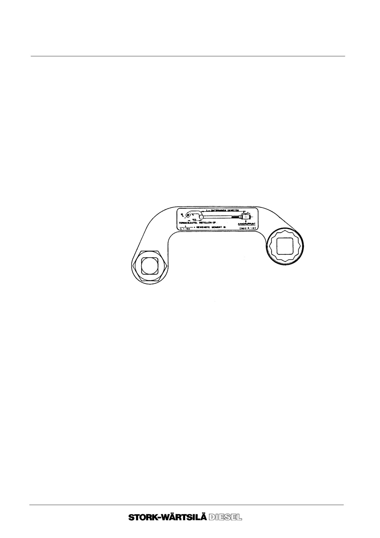
9612 F 911 A Tool for removal / fitting the main bearing nuts.
------------------------------------------------------------------------------------------------------------------------------------
Item No.
Description
Tool No.
Qty
------------------------------------------------------------------------------------------------------------------------------------
1.
BOOMERANG SPANNER
9612 F 010
1
On the spanner a formula has either been punched in or stuck on. In this formula, L is
the length of the torque spanner from the centre of the handgrip to the centre of the pivot
on the spanner extension. The formula is applicable if the torque spanner is used in line
with the boomerang spanner. If the torque spanner is used at right angles to the
boomerang spanner, there will be no change in torque.
Ver. 01
11 -- 1
Manual
F 240
MAIN BEARINGS
11A NECESSARY TOOLS
Tool B
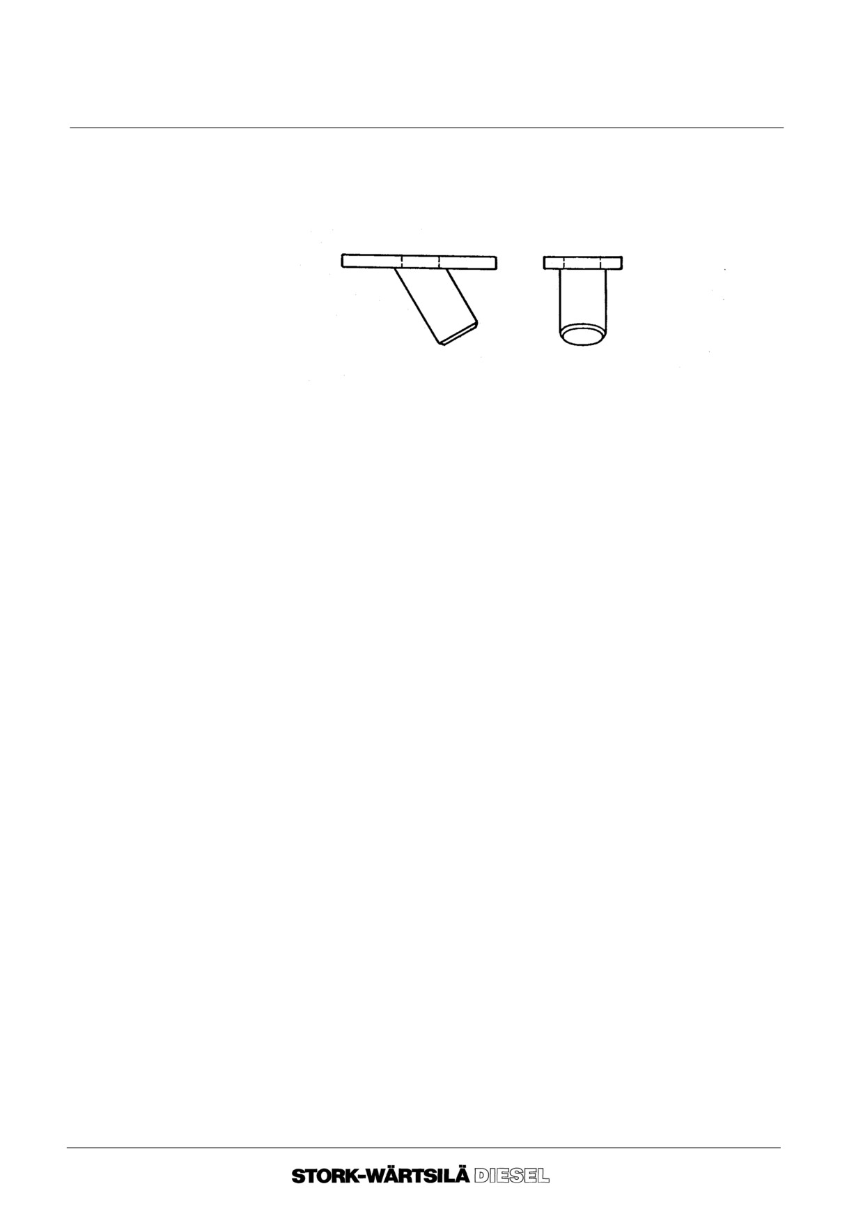
9612 F 008
Driver.
Used to drive the lower bearing shell from under the crankshaft.
Ver. 01
11 -- 2
Manual
F 240
MAIN BEARINGS
11A NECESSARY TOOLS
Tool C
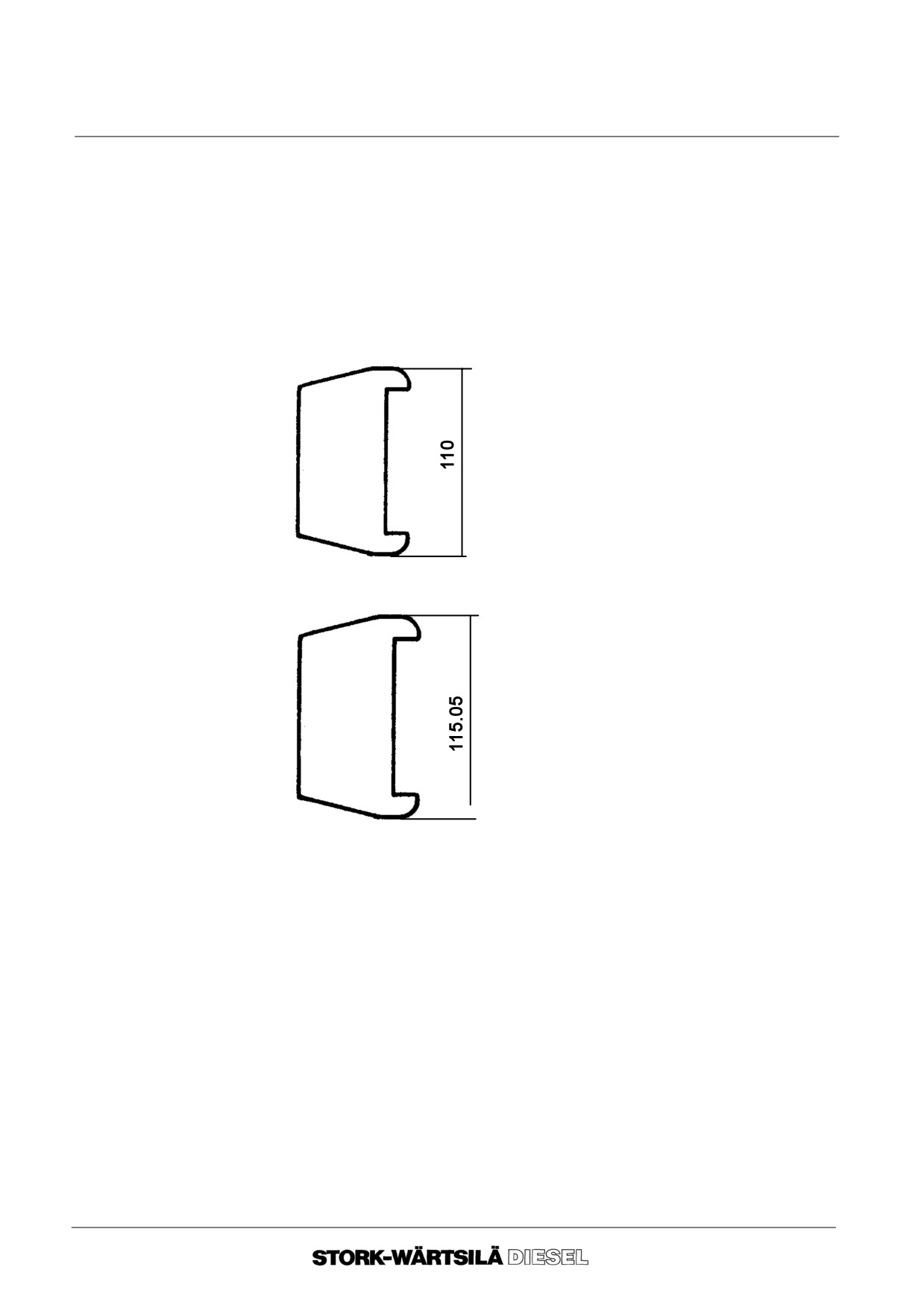
9612 F 200
Jig (C1)
for locating main bearing bottom shell.
9612F201
Jig (C2)
for locating axial main bearing bottom shell.
Y
C1
B
Y
C2
B
--o--o--o--o--o--
Ver. 01
11 -- 3
Manual
F 240
MAIN BEARINGS
11B REMOVAL
Before starting work, please consult:
-- chapter 2 -- BACKGROUND INFORMATION ;
-- chapter 3 -- TECHNICAL DATA.
1.
Remove crank case covers on both sides of the bearing.
2.
Disconnect the lube oil supply pipe to the main bearing cap.
3.
Loosening of the main bearing cap nuts and upper bearing shell:
3. 1. Fold back the locking plate and undo the main bearing nuts. The nuts can
normally be undone with a long ratchet spanner, but if they cannot be
reached in this way, the boomerang spanner, Tool A, can be used as an
extension to the ratchet.
3. 2. Remove the bearing cap with the upper bearing shell.
Mark the bearing shell e.g. with a felt--pen, so that the used bearing
shell can be placed in exactly the same position and in the same place.
4.
Removal of the lower bearing shell:
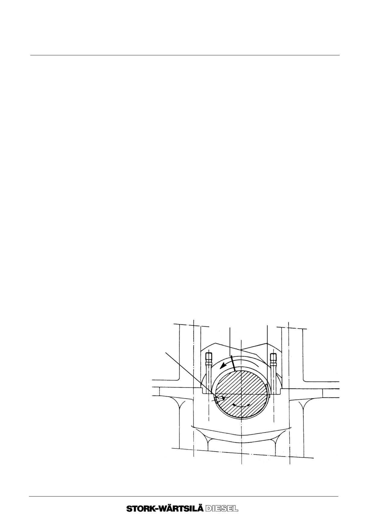
4. 1. Fit the driver into the oil channel of the crankshaft. If necessary, turn the
engine first.
4. 2. The direction of rotation is indicated in the figure.
Pay attention to positioning lug ”A”.
Carefully turn the driver against the bearing shell until it is turned out.
Remove the bearing shell.
Mark the bearing shell e.g. with a felt--pen, so that the used bearing
shell can be fitted in exactly the same position, and in the same place.
4. 3. Turn further so that the driver can be removed.
Jig
”A” Positioning lug
Driver
--o--o--o--o--o--
Ver. 01
11 -- 4
Manual
F 240
MAIN BEARINGS
11C REPLACEMENT
Before starting work, please consult:
-- chapter 2 -- BACKGROUND INFORMATION ;
-- chapter 3
-- TECHNICAL DATA.
1.
Carefully clean and dry the bearing saddle, the bearing cap, the bearing shells and
crankshaft with a lint free cotton cloth.
2.
Replacement of the lower bearing shell:
2. 1. Fit the driver into the oil channel of the crankshaft. If necessary, turn the
engine first.
2. 2. Turn back the engine until the bearing shell can be fitted.
Lubricate the running layer of the bearing shell sparingly with engine oil. The
back surface must remain dry!
Always refit used bearing shells in exactly the same position and in the same
place.
Place the end of the bearing shell in the slot between the journal and the
bearing saddle. Mind the positioning lug.
Centre it with the jig, Tool C, and push it in by hand as far as possible, (about
1/3 of its length).
2. 3. Slowly turn the driver against the bearing shell joint. Turn the bearing shell
slowly into position until the bearing shell joints are about level with the
joining faces of the cylinder block. The joints must be thoroughly cleaned.
Whilst turning the bearing, keep one hand on the exposed surface, and
make sure the bearing shell stays in contact with the crank shaft journal.
2. 4. Turn back and remove the driver.
3.
Make sure that the positioning the lug of the lower bearing shell, engages with the
recess in the bearing saddle.
4.
Replacement of the upper bearing shell and the bearing cap:
4. 1. Carefully clean the bearing cap bore and the abutting faces of the bearing
cap.
4. 2. Place the upper bearing shell in position (the one with the oil groove). Mind
the positioning lug.
4. 3. Lubricate the running layer of the bearing shell sparingly with engine oil. The
back surface must remain dry.
4. 4. Fit the bearing cap together with the upper half shell into position.
4. 5. Make sure the bearing shells are in line.
5.
Tightening the bearing cap:
5. 1. Prior to tightening the main bearing cap nuts, lubricate the threads on the
studs and the nuts sparingly with engine oil.
5. 2. Use new locking plates and tighten the bearing cap nuts diagonally in two
steps to the torque specified in chapter three Technical Data.
5. 3. Secure the bearing cap nuts by means of the locking plates.
Ver. 01
11 -- 5
Manual
F 240
MAIN BEARINGS
11C REPLACEMENT
6. Connect the lube oil supply pipe to the main bearing cap, Use a new gasket and
locking plate.
7. Remove any object from the engine crankcase.
8. Pre--lubricate the engine and check if the bearing is getting oil.
9. Fit the crankcase covers.
10. Start up the engine for running in.
--o--o--o--o--o--
Ver. 01
11 -- 6
Manual
F 240
CYLINDER BLOCK
13A INTERNAL INSPECTION
Before starting work, please consult:
-- chapter 2, ”BACKGROUND INFORMATION”.
11. Crankshaft space
For safety reasons, before removing all crankcase covers:
--
close starting air supply to the engine ;
--
open decompression cocks;
Attention must be paid to the following :
--
the axial movement of the big end of the connecting rod on the crank pin journal
--
carbon build-up under or near the cylinder liners ;
--
local discolouration of the paint ;
--
fouling and the presence of impurities ;
--
the presence of metal particles ;
--
water leakage, notably around the cylinder liners ;
--
running face of the gear wheels ;
--
when a piston is at its T.D.C., part of the associated cylinder liner can be
examined ;
--
the locking arrangement of the con rod nuts ;
--
the welds locking the counter weight bolts in place ;
--
when a piston is at its B.D.C., part of the associated piston can be examined ;
--
start pre--lubricating pump and check for internal leakage.
12. Cooling water
For inspection of the cooling water spaces around the cylinder liners it is necessary
spaces
to remove one or more cylinder liners.
For removal of cylinder liners, please consult chapter 15C.
By removing the covers of the cooling water supply channel this space can be
inspected.
The cooling water spaces have to be visually inspected on the following:
-- Serious corrosion ;
-- Cavitation ;
-- Sludge formation ;
-- Line deposits and any other abnormalities.
--o--o--o--o--o--
Ver. 01
13 -- 1
Manual
F 240
CYLINDER BLOCK
13A INTERNAL INSPECTION
Ver. 01
13 -- 2
Manual
F 240
EXPLOSION VALVE
14A CHECKING
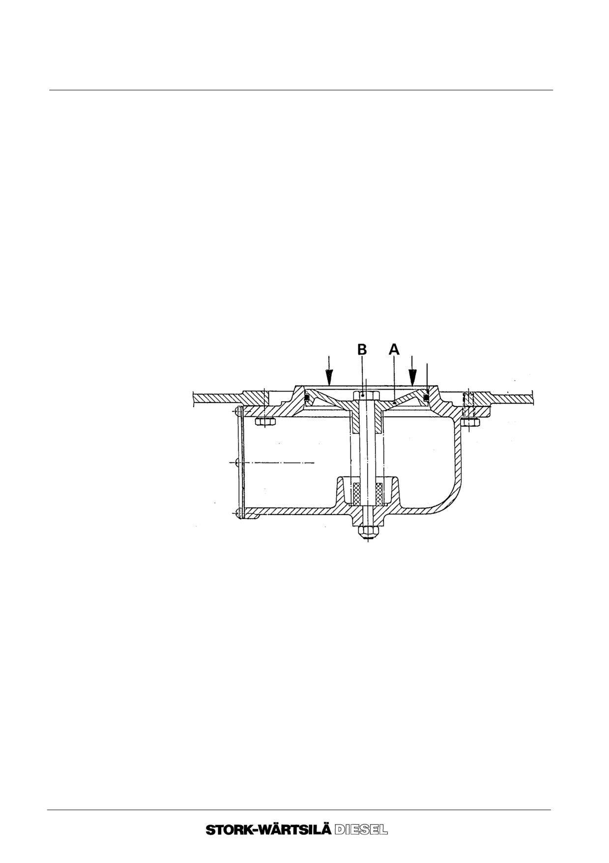
Before starting work, please consult:
-- chapter 2, ”BACKGROUND INFORMATION”.
13. Remove the crankcase cover complete with explosion valve.
14. Put the crankcase cover with the housing of the explosion valve downwards.
15. Push with a force between 25 and 30 kgs on the valve (A). The valve should now
open. Push again with a larger force, so that the valve can open completely.
Attention!
When the valve can not be opened or only partly, remove valve A with guide bolt B.
Clean the valve seat, valve and guide bolt and make them to run easily again. Fit
the valve using a new O--ring.
16. Replace the crankcase cover complete with explosion valve.
O--ring
--o--o--o--o--o--
Ver. 01
14 -- 1
Manual
F 240
EXPLOSION VALVE
14A CHECKING
Ver. 01
14 -- 2
Manual
F 240
CYLINDER LINER
15A NECESSARY TOOLS
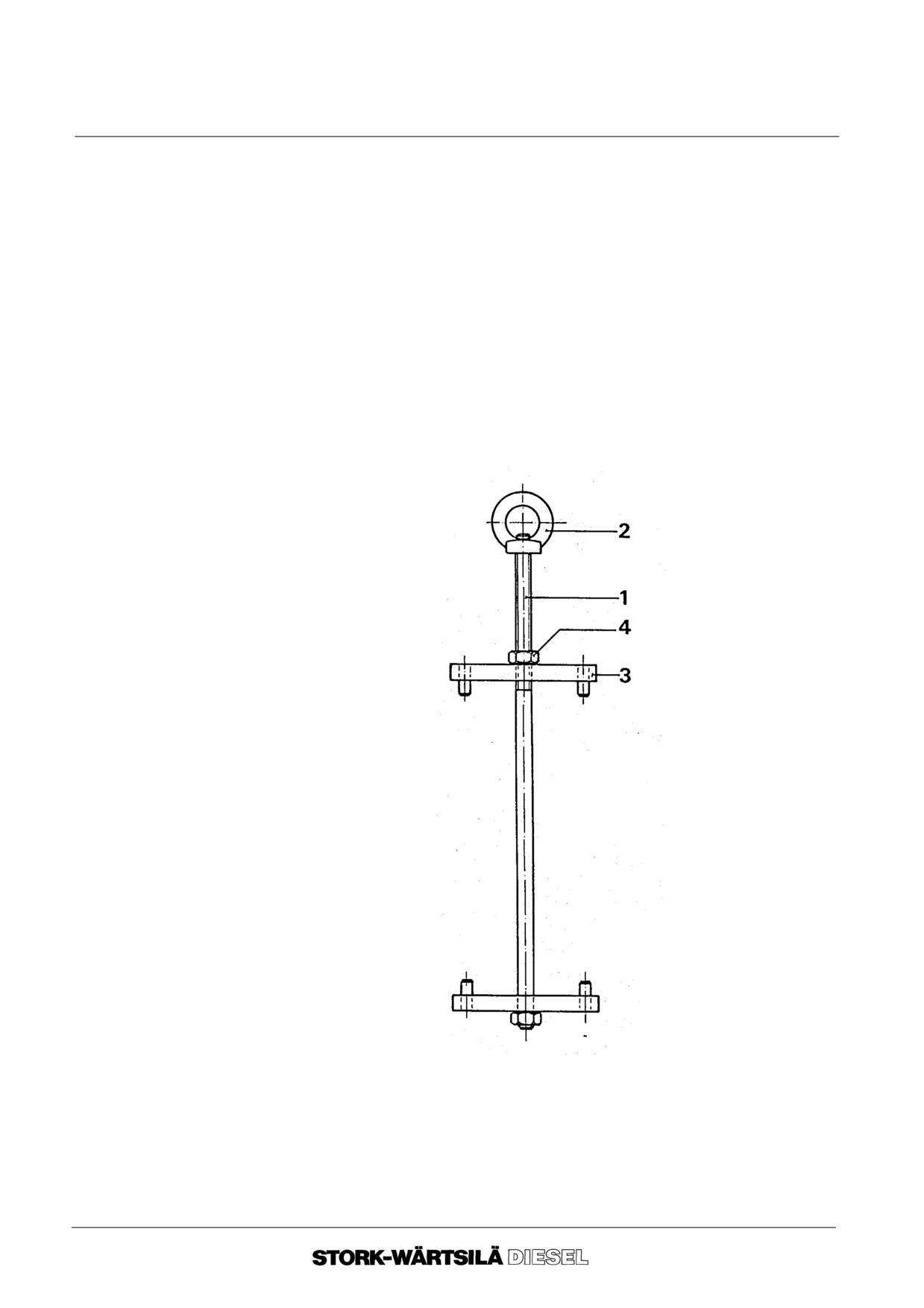
Tool A
1
Threaded rod. This runs along the length of the liner, and connects the top and
bottom flanges.
Tool number : 9612F145.
2
Eye nut. This screws on to the top of the threaded rod, and is then attached
to the hoist.
Tool number : 9612F147.
3
Flange for mounting and removing of the liner. These fit at the top and bottom
of the liner, and are used to lift it out of the cylinder block.
Tool number : 9612F215 . (2x)
4
Nut M30. Used to hold the flanges against the liner.
Tool number : 0185--020.
--o--o--o--o--o--
Ver. 01
15 -- 1
Manual
F 240
CYLINDER LINER
15B INSPECTION
Before starting work, please consult:
-- chapter 2, ”BACKGROUND INFORMATION” ;
-- chapter 3, ”TECHNICAL DATA”.
17. Endoscope
The use of an endoscope takes some practice and experience. In most cases, it is
inspection
rather difficult to interpret correctly the pattern observed.
Therefore, it is recommended to have endoscope inspections carried out by service
engineers of Stork Wärtsilä Diesel.
The cylinder liner can be inspecteded visually without removing the cylinderhead,by
using an endoscope.
The cylinder liner can be inspected through the nozzle hole in the cylinder head, from
which the nozzle with holder must first be removed.
For removal and refitting the nozzle with holder see chapter 17.
18. Inspection points
Inspect the cylinder liner for the following points :
-- scratches ;
-- honing pattern ;
-- burnt spots ;
-- lacquer formation ;
-- shiny stains or bands ;
-- carbon deposits inside the combustion chamber.
--o--o--o--o--o--
Ver. 01
15 -- 2
Manual
F 240
CYLINDER LINER
15C REMOVAL
Before starting work, please consult:
-- chapter 2, ”BACKGROUND INFORMATION” ;
-- chapter 3, ”TECHNICAL DATA”.
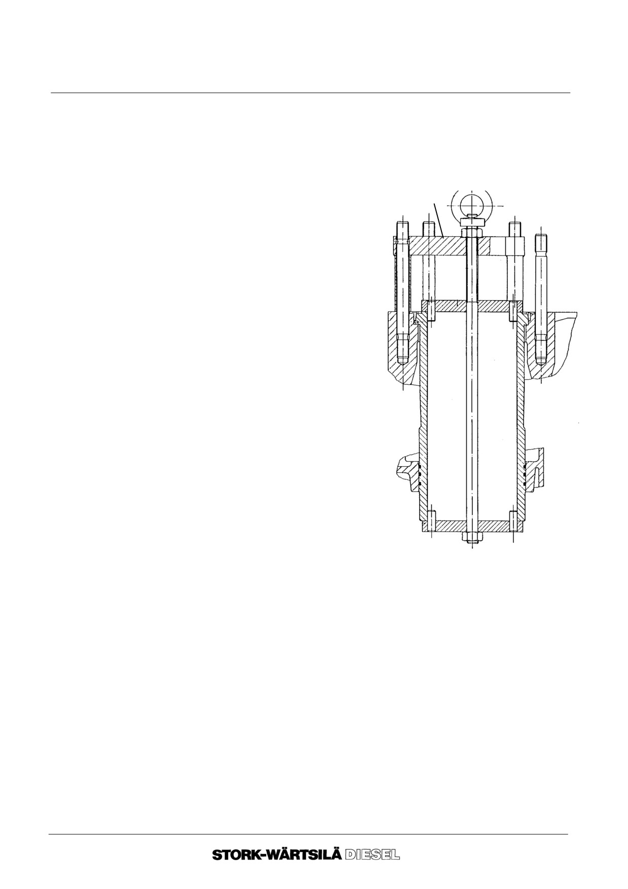
bridge
1. Remove the cylinder head. See section
piece
18B.
2. Remove the piston and connecting rod
assembly. See section 16E.
Tool A
3.
Removal cylinder liner:
3. 1. Place the upper flange on the
cylinder liner top edge.
3. 2. Fit the lower flange with the
threaded rod and nut M30 and
screw the second nut onto the top
of the threaded rod.
3. 3. Protect the crankpin and provide
in the crankcase a facility allowing
any residual cooling water or dirt
to be collected.
3. 4. Screw the eye nut onto the
threaded rod and hoist the liner
out of the cylinder block.
It may be necessary to use a
bridge piece over the cylinder
head studs as shown, to loosen
the cylinder liner. This is not a
standard delivery tool.
4.
Clean and inspect the cooling water jacket.
--o--o--o--o--o--
Ver. 01
15 -- 3
Manual
F 240
CYLINDER LINER
15D FITTING
Before starting work, please consult:
-- chapter 2, ”BACKGROUND INFORMATION” ;
-- chapter 3, ”TECHNICAL DATA”.
1.
When fitting a new or honed cylinder liner,
the piston rings must be renewed.
Proceed as follows.
2.
First, clean the liner collar carefully inside
and outside as well as the location of the
O--ring seals.
3.
Check the supporting edge and the gas
sealing face of the cylinder liner for
damage.
The gas sealing face can be ground with
the grinding ring.
4.
Apply Molykote G--n--plus paste:
Attention!
When fitting a cylinder liner, always use
new O--rings. Fit the O--rings with silicone
grease. Stretch the O--rings as little as
possible. The O--rings may not be twisted
after they have been fitted.
Molykote
O--rings
Apply a thin, even film of Molykote
G--n--plus
G--n--plus paste, as shown in the figure.
Remove any excess paste.
5.
Clean the cooling water spaces in the cylinder block and inspect them.
6.
Clean the supporting face and the lower and upper bores of the cylinder block.
Check the supporting face and the bores for damage.
The supporting face can be ground with the grinding ring.
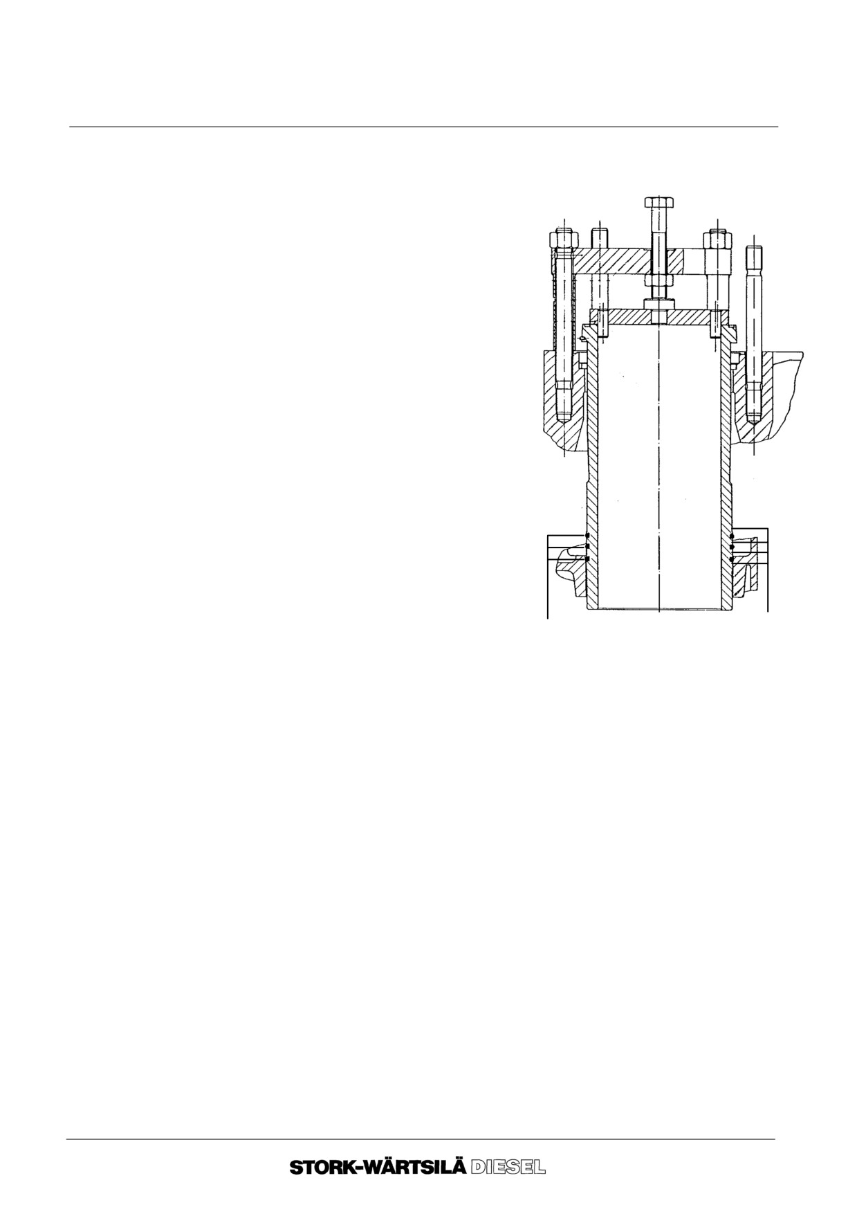
Tool A
7.
Hoisting the cylinder liner:
7. 1. Hoist the cylinder liner into the cylinder block with the aid of the flanges, the
threaded rod and nuts.
It may be necessary to push the cylinder liner into its recess to make it fit. This
can be done using a bridge piece over the cylinder head studs as shown.
This is not a standard delivery tool.
7. 2. Detach the hoisting gear.
8.
Fit piston and con rod assembly. See section 16K.
9.
Fit cylinder head. See section 18C.
--o--o--o--o--o--
Ver. 01
15 -- 4
Manual
F 240
PISTON AND CONNECTING ROD
16A GENERAL DESCRIPTION
10.
Piston
The piston tightens in the cylinder by means of three compression rings and is
equipped with one oil scraper ring. Dismantling of the piston with connecting rod is only
possible after dismantling the cylinder head.
The steel top part of the piston may not be removed other than in consultation with
the Service Department of Stork--Wärtsilä Diesel. This means that piston heads must
on no account be removed when a routine maintenance job is being effected.
Quick pollution of the pistons may be caused by fuel or lubricating oil of inferior quality,
bad combustion or high lubricating oil consumption.
Stuck piston rings cause loss of power due to escape of air and combustion gases into
the crankcase, which can be detected by excessive crankcase pressure and oil
leaving the sump.
Oil incrustations on the piston should be scraped away carefully, after which the piston
should thoroughly cleaned with gasoil.
Generally it is not necessary to remove the connecting rod from the piston as long as
it moves freely round the gudgeon pin without excessive clearance.
If dismantling of the connecting rod should be necessary remove the locking rings from
the gudgeon pin and push the pin out. It is then possible to remove the connecting rod
from the piston.
Make sure the piston rings move easily in their grooves.
Damaged piston rings should be replaced.
When fitting new piston rings the utmost care must be taken in order not to damage,
deform or break the rings.
When fitting rings care should be taken that they are fitted with the word ”Top” to the
top side.
If piston rings that have been used are fitted again, there is the disadvantage that any
unroundness that may have arisen which is difficult to prevent, will only disappear after
a long time by running in.
This may not only be the cause of a high consumption of lubricating oil, but also of
leakage of exhaust gases and pollution of the engine.
Before fitting the new piston rings the grooves in the piston should be oiled. Put the
lock ring for the gudgeon pin back in place and the nuts of the connecting rod bolts
must be tightened with the correct torque and locked in the right way.
When working on the pistons, care should be taken to prevent mechanical damage.
This is particularly important for light metal pistons.
Attention should also be paid that nothing hits the piston when it is hoisted.
Put the piston down by preference on soft material e.g. wood.
Especially the banging of the connecting rod against the piston skirt may cause serious
damage and should always be avoided.
The concerning rod may only be put to rest against the piston skirt very carefully, so
without even the slightest shock.
The connecting rods are open heart steel forgings. The rods are drilled through for the
11. Connecting rod
lubrication oil supply from big end bearing shells to the small end bearing shell.
The small end bearing in the connecting rod is constructed as eye bearing, whilst the
big end bearings are precision bearing shells.
If only the big end bearing shells have to be inspected or replaced, it is not necassary
to remove the piston with connecting rod.
--o--o--o--o--o--
Ver. 01
16 -- 1
Manual
F 240
PISTON AND CONNECTING ROD
16B NECESSARY TOOLS
Tool A
9612 F 920 A Set of tools for removal / fitting the piston with
connecting rod.
------------------------------------------------------------------------------------------------------------------------------------
Item No.
Description
Tool No.
Qty
------------------------------------------------------------------------------------------------------------------------------------
1.
CLAMPING RING
9612 F 007
1
2.
HOISTING RING
9612 F 015
1
3.
HOLDER
9612 F 266
1
4.
SNAP--ON PIN
9612 F 017
1
5.
LEVER
9612 F 188
1
6.
SUPPORTING STRIP
9612 F 191
1
7.
BOLT
0141 ..168
2
8.
HOLDING PLUG
9612 F 225
2
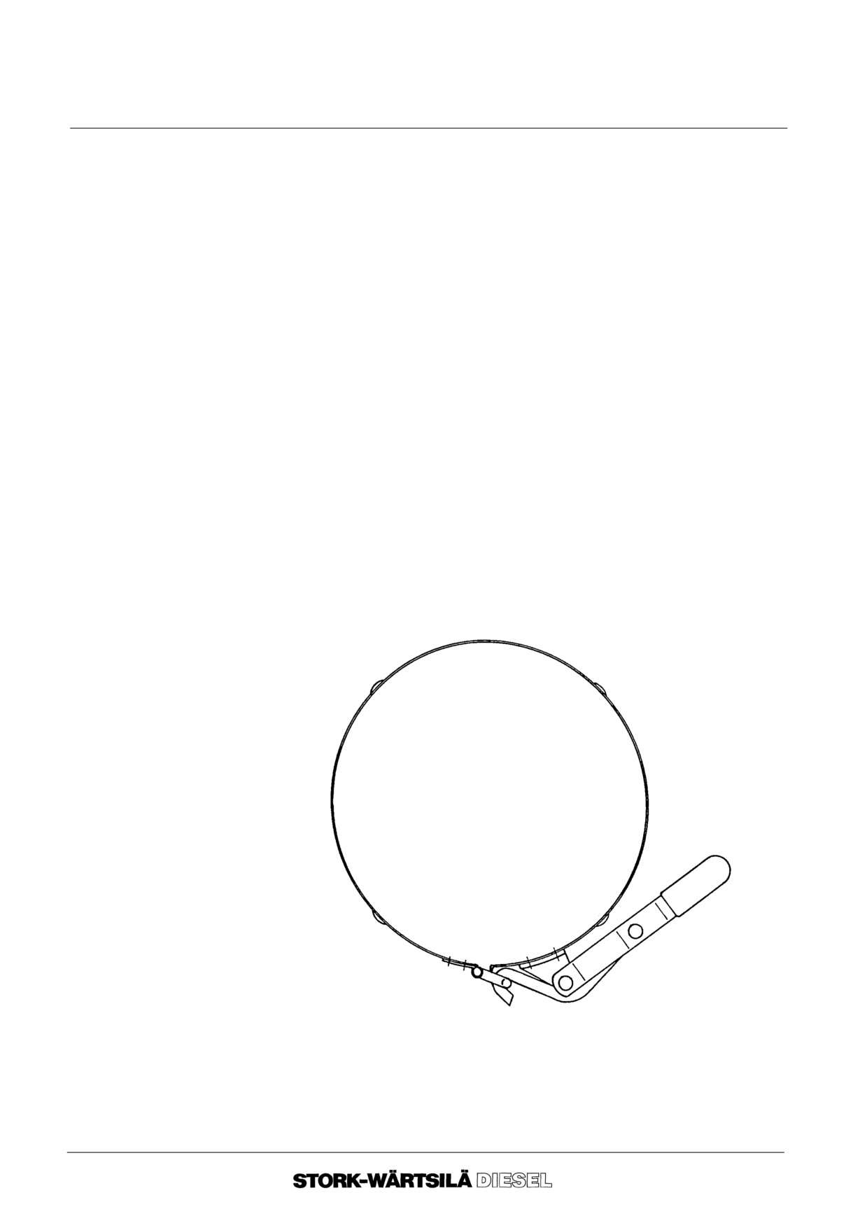
Item 1
CLAMPING RING.
Used to hold the piston rings in place whilst fitting the piston back into the liner.
Ver. 01
16 -- 2
Manual
F 240
PISTON AND CONNECTING ROD
16B NECESSARY TOOLS
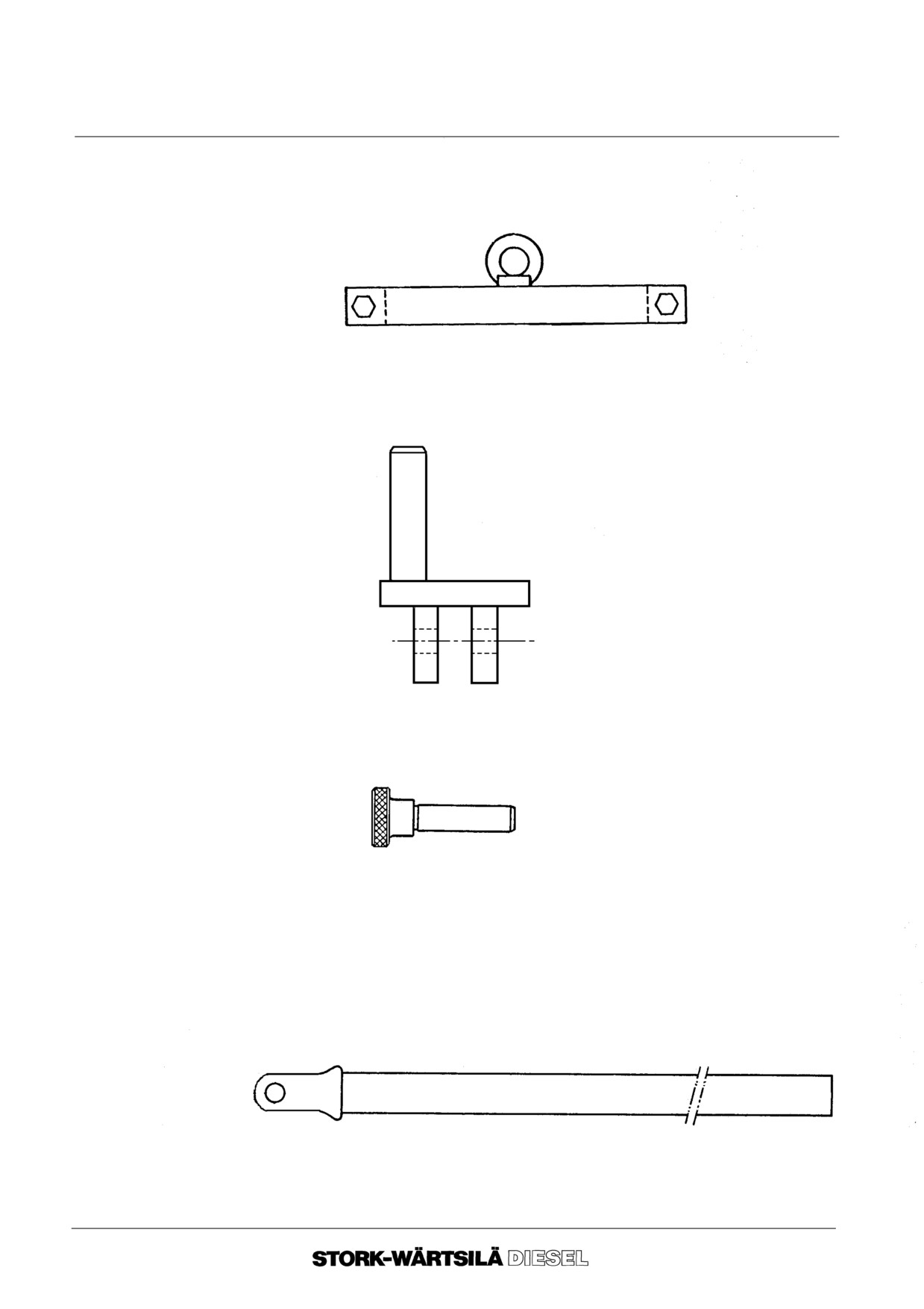
Item 2
HOISTING RING.
This ring clamps around the top of the piston, and thereby enables it to be hoisted.
Item 3
HOLDER.
This tool fits under the connecting rod, and is used, on the end of the lever, to push the
piston and connecting rod out of the liner.
Item 4
SNAP--ON PIN.
This is the joining pin which holds the piston holder and the lever together.
Item 5
LEVER.
Used to push the holder and piston upwards, out of the liner.
Ver. 01
16 -- 3
Manual
F 240
PISTON AND CONNECTING ROD
16B NECESSARY TOOLS
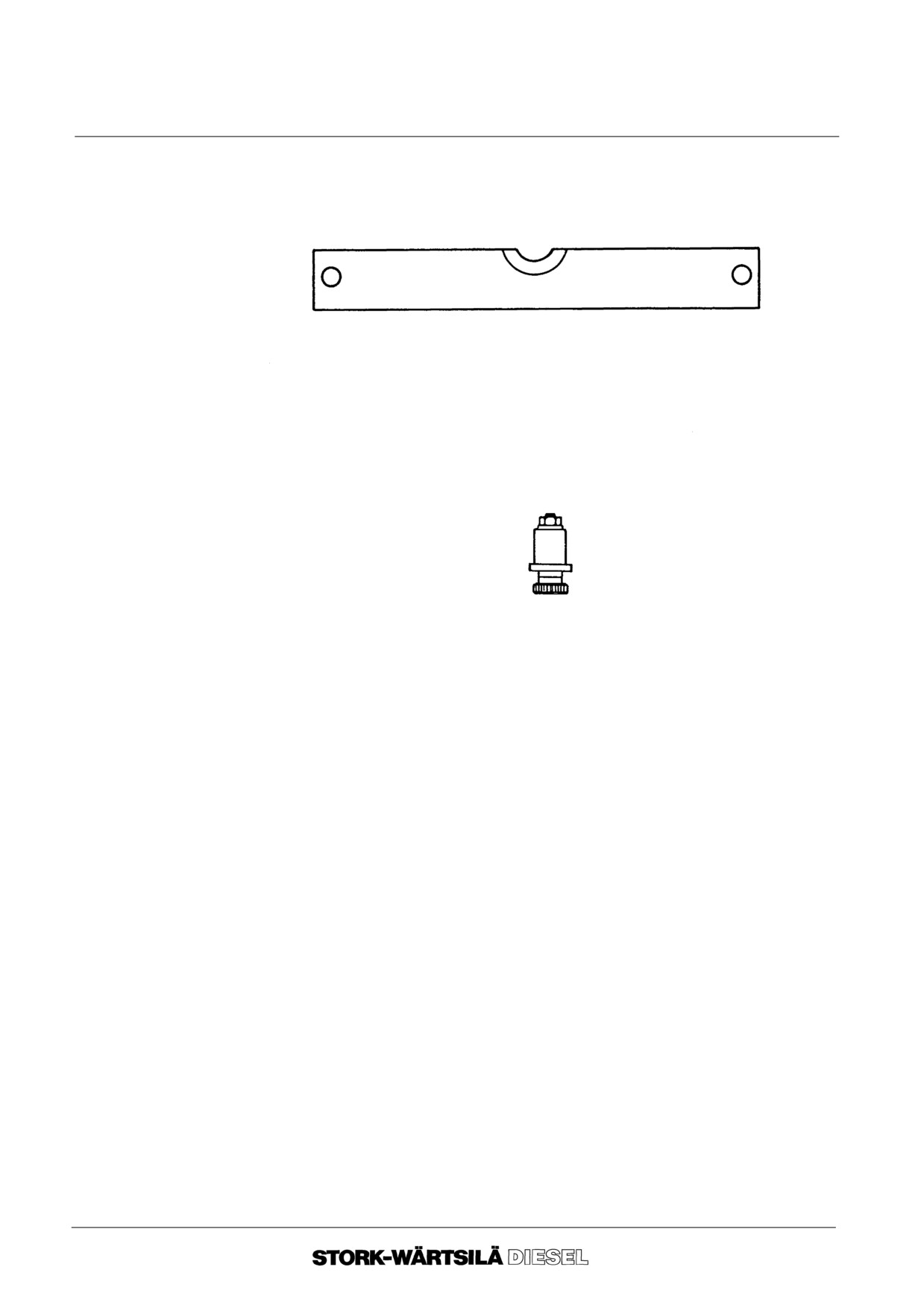
Item 6
SUPPORTING STRIP.
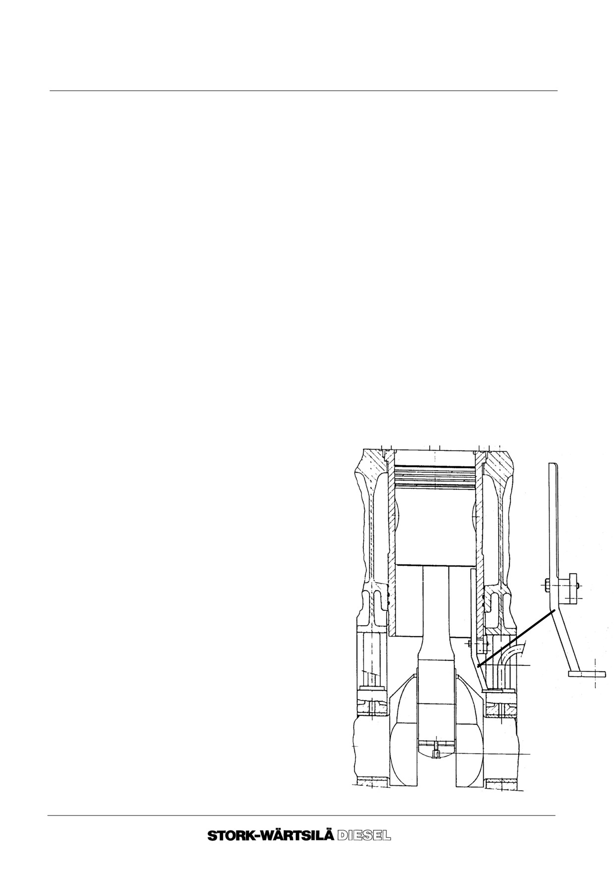
This strip gets bolted across the crank case opening and acts as a pivot for the lever
used to force the piston out of the liner.
Item 7
BOLT (2x).
The two bolts used to attach the support strip.
Item 8
HOLDING PLUG (2x).
These hold the upper bearing shell in place whilst the piston and connecting rod are
being hoisted out of the liner.
Ver. 01
16 -- 4
Manual
F 240
PISTON AND CONNECTING ROD
16B NECESSARY TOOLS
Tool B
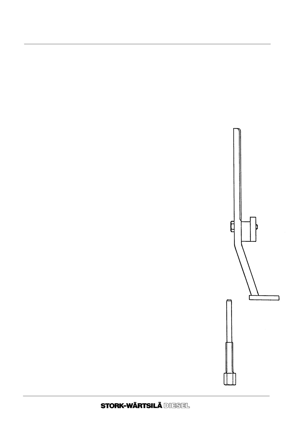
9612 F 910 A Tool for removal the connecting rod cap and the crankpin
bearing shell.
------------------------------------------------------------------------------------------------------------------------------------
Item No.
Description
Tool No.
Qty
------------------------------------------------------------------------------------------------------------------------------------
1.
PISTON SUPPORT
9612 F 009
1
1.
JACK BOLT
9612 F 017
2
Item 1
PISTON SUPPORT.
This sits on a main bearing cap, and clamps against a cylinder
liner during the changing of a big end bearing, in order to
support the weight of the piston.
Item 2
JACK BOLTS.
These force the connecting rod cap off the connecting rod if,
after a period of service, it has become jammed on.
Ver. 01
16 -- 5
Manual
F 240
PISTON AND CONNECTING ROD
16B NECESSARY TOOLS
Tool C
66333--900
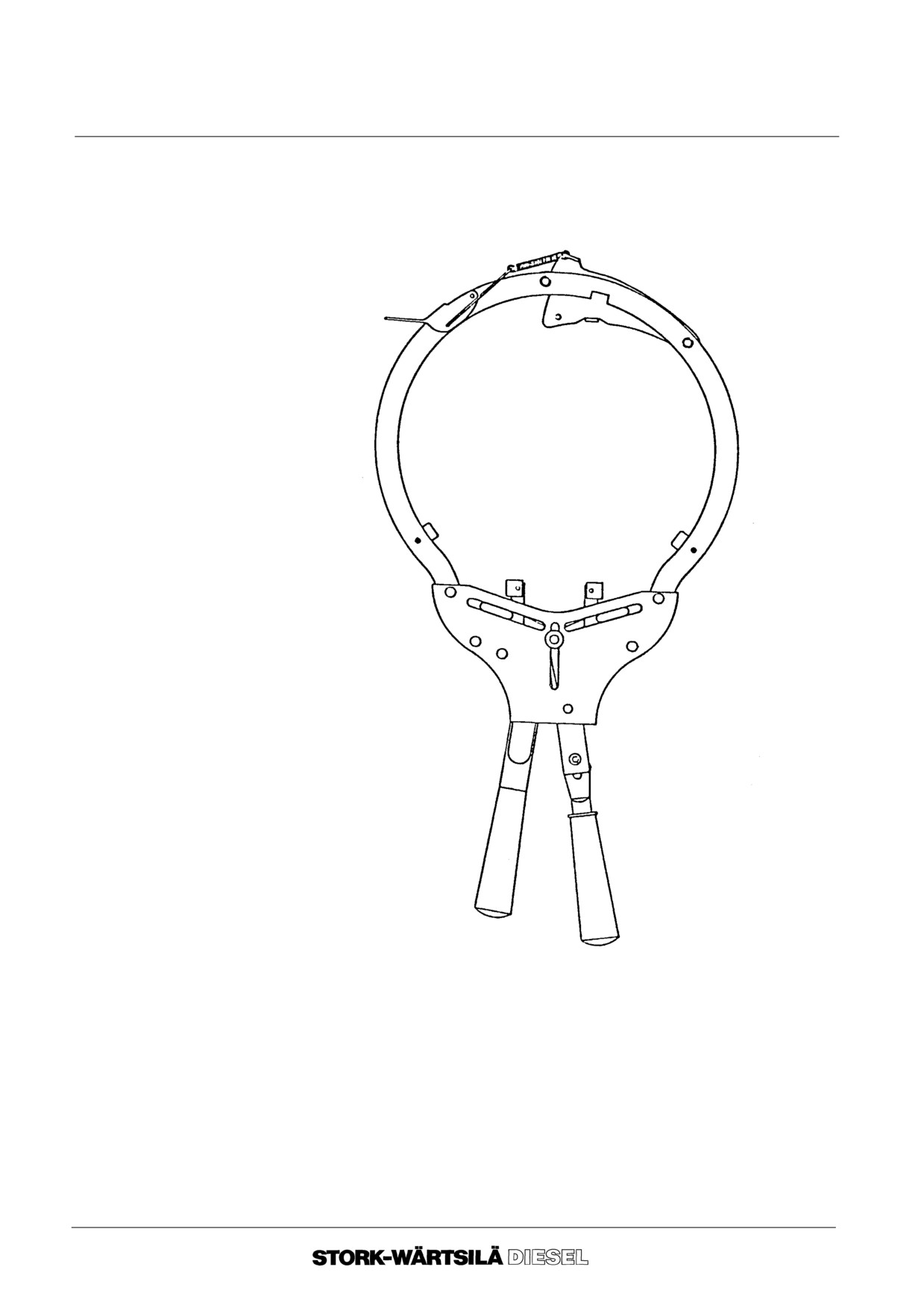
Piston ring pliers
For removal / fitting of piston rings without damage or deformation.
--o--o--o--o--o--
Ver. 01
16 -- 6
Manual
F 240
PISTON AND CONNECTING ROD
16C REMOVAL BIG END BEARING
Before starting work, please consult:
-- chapter 2, ”BACKGROUND INFORMATION”.
If only the big end bearings have to be inspected or replaced, it is not necessary to remove
the piston and connecting rod.
1.
Remove the crank case covers of the bearing to be removed.
Tool A
2.
Removal of connecting rod cap:
2. 1. Tap the folded locking plates under the connecting rod nuts straight.
2. 2. Loosen the connecting rod nuts. First slacken the nuts to prevent the connecting
rod cap from falling into the sump. If the cap sticks to the foot, use two jack bolts,
Tool B item 2, to release the connecting rod cap with the bottom bearing shell
from the connecting rod foot.
2. 3. Turn the piston to Top Dead Centre.
2. 4. Remove three connecting rod bolts.
2. 5. Holding on to the connecting rod cap, take out the fourth connecting rod bolt.
BEWARE of the weight.
2. 6. Remove the connecting rod cap.
Tool A + B
3.
Removal of the upper bearing shell:
3. 1. Place two holding plugs,
Tool A item 8, diagonally in
the bolt holes of the
connecting rod foot to
keep the upper bearing
shell from falling out.
3. 2. Position the support for
the piston, Tool B, in such
a way that the support
base rests on the main
bearing cap, and fit the
bolt with the other end of
the holder inside the
cylinder liner, around the
bottom end of the liner,
and under the piston and
make sure the securing
plate is tightened.
3. 3. Carefully turn away the
crank pin from under the
piston and connecting
rod.
Ver. 01
16 -- 7
Manual
F 240
PISTON AND CONNECTING ROD
16C REMOVAL BIG END BEARING
3. 4. Pull the holding plugs out of the connecting rod foot bolt holes, and remove the
crank pin upper bearing shell.
4. Mark the bearing shells halves of each cylinder with e.g. a felt--pen, because when
the used shells have to be re--used, it has to be done in exactly the same position
and in the same place.
Attention!
Bearing shells can be placed back depending on the wear pattern, the running
hours and on the condition of the running surface.
--o--o--o--o--o--
Ver. 01
16 -- 8
Manual
F 240
PISTON AND CONNECTING ROD
16D FITTING BIG END BEARING
Before starting work, please consult:
-- chapter 2, ”BACKGROUND INFORMATION” ;
-- chapter 3, ”TECHNICAL DATA” .
1.
Pay attention to the following points during the fitting procedure:
1. 1. The fitting procedure of big end bearings has to be completed for each
connecting rod separately in order to avoid displacement of the bearing
shells and oil leakage to the back surface of the bearings.
1. 2. Bearing shells can be placed back depending on the wear pattern, the
running hours and on the condition of the running surface.
Used bearing shells must be replaced in exactly the same position (see
marking on the bearing shells).
2.
Thoroughly clean and dry the connecting rod foot with a lint free cotton cloth.
Only lubricate the running layers of the bearing shells sparingly with engine
oil! The back surface of the bearing shells must remain dry!
Tool A
3.
Fitting upper bearing shell:
3. 1. Fit the crank pin upper bearing shell in to the connecting rod foot. This shell
has no oil holes.
3. 2. Prevent the bearing shell from falling out by placing two holding plugs in two
diagonally opposite bolt holes, (item 8).
3. 3. Check if the bearing shell lug engages properly with the slot in the
connecting rod foot.
3. 4. Lubricate the crank pin sparingly with clean lubrication oil.
3. 5. Before turning the crankshaft in the connecting rod foot, make sure that the
bore and the faces of the connecting rod foot are clean, dry, and
undamaged.
3. 6. Turn the crank pin carefully under the connecting rod foot.
3. 7. Pull the holding plugs out of the connecting rod foot bolt holes.
3. 8. Check again that the bearing shell lug engages properly with the slot in the
connecting rod foot.
Tool B
4.
Fitting of the bearing cap:
4. 1. Fit the lower bearing shell in to the connecting rod cap. This shell is
identifiable by the longitudinal oil groove with lubrication oil holes.
4. 2. Check if the bearing shell positioning lug engages properly with the slot in the
connecting rod cap.
4. 3. Lubricate the bearing shell running surface sparingly with clean lubrication
oil. The back surface MUST remain dry!!
Fit the connecting rod bearing cap. Beware of the weight of the cap.
4. 4. Make sure that the serial numbers on the connecting rod foot and the
connecting rod cap correspond and are located above one another.
Ver. 01
16 -- 9
Manual
F 240
PISTON AND CONNECTING ROD
16D FITTING BIG END BEARING
4. 5. Fit the connecting rod bolts with new locking plates.
4. 6. Screw the connecting rod nuts hand--tight, diagonally, after lubricating the
thread flanks and the contact faces sparingly with clean lubrication oil.
4. 7. The connecting rod bolts have one flat side which needs to face towards the
cap.
4. 8. Remove the piston support.
5. Tighten the connecting rod nuts diagonally in two steps, to the torque specified in
chapter three Technical Data.
6. Tap the corners of the locking plates up against the nuts.
7. Check if the connecting rod has enough play around the crank pin.
It must now be possible to move the connecting rod easily in the axial direction. If
not, the cause must be found.
8. Prelubricate the engine and check if the bearing is getting oil.
9. Replace the crankcase covers.
--o--o--o--o--o--
Ver. 01
16 -- 10
Manual
F 240
PISTON AND CONNECTING ROD
16E REMOVING
Before starting work, please consult:
-- chapter 2, ”BACKGROUND INFORMATION” ;
-- chapter 3, ”TECHNICAL DATA”.
If only the big end bearings have to be inspected or replaced, it is not necessary to remove
the piston and connecting rod.
1.
Remove the cylinder head, see section
18B.
2.
Remove the carbon build--up from the
liner edge. Do not use a sharp object
A
for this purpose.
3.
Remove the connecting rod cap. See
section 16B.
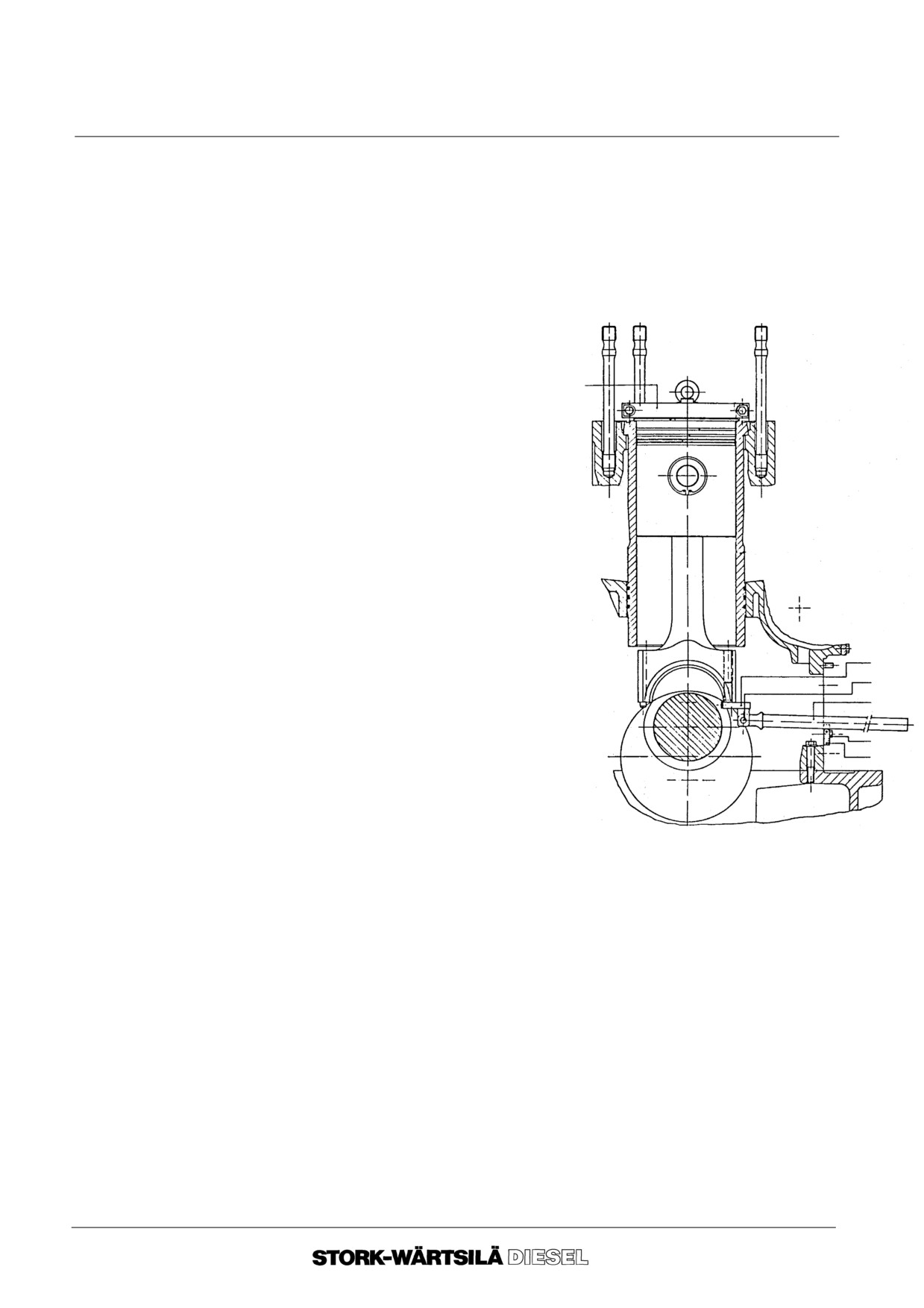
Tool A
4.
Fixing the piston and connecting rod:
4. 1. Turn the piston to Top Dead
Centre.
4. 2. Place two holding plugs, item 8,
into two diagonally opposite bolt
holes in the con rod foot to
prevent the upper bearing half
shell from falling.
G
D
4. 3. Fit the support strip B, to the
E
cylinder block using the bolts.
4. 4. Place the holder G, coupled to
B
the lever E, by means of the pin
D, in the con rod foot.
4. 5. Using the lever, force the piston
and con rod upwards so that the upper piston ring comes to rest on the cylinder
liner edge.
4. 6. Remove the holder and lever assembly, pull the holding plugs out of the
connecting rod foot, and remove the upper bearing shell.
Tool A
5.
Removing the piston and connecting rod:
5. 1. Remove the carbon of the piston top side.
5. 2. Fit the hoisting ring, item A.
The eye bolt faces must be level with the top of the piston.
5. 3. Hoist the piston and con rod assembly out of the cylinder liner.
5. 4. Protect the crankpin.
--o--o--o--o--o--
Ver. 01
16 -- 11
Manual
F 240
PISTON AND CONNECTING ROD
16F REMOVAL OF GUDGEON PIN
Before starting work, please consult:
-- chapter 2, ”BACKGROUND INFORMATION”.
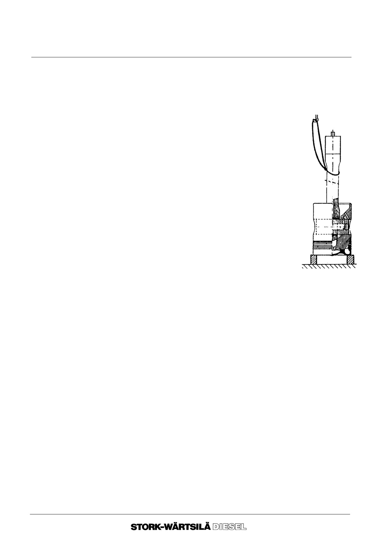
1. Remove piston and connecting rod. See chapter 16D.
2. Place the piston and connecting rod on a wooden block.
3. Lift the connecting rod so far that the weight is free from the
gudgeon pin.
4. Remove one circlip.
5. Remove the gudgeon pin.
If necessary, use a hammer and a copper bar. Do not touch the
inner cap of the gudgeon pin, and avoid damage to the piston.
If the gudgeon pin sticks, it is allowed to heat the aluminium
piston skirt evenly to about
30oC above the ambient
temperature.
6. Lift the connecting rod out of the piston. Keep gudgeon pin,
piston and connecting rod of the same cylinder together!
For inspection of parts, consult chapter 3, ”TECHNICAL DATA”
(No--Go criteria).
--o--o--o--o--o--
Ver. 01
16 -- 12
Manual
F 240
PISTON AND CONNECTING ROD
16G FITTINGOF GUDGEON PIN
Before starting work, please consult:
-- chapter 2, ”BACKGROUND INFORMATION”.
1. Clean all parts carefully prior to fitting. Take care not to damage the aluminium
piston skirt! Never use emery cloth.
2. Place the piston crown on a wooden block.
3. If both inner circlips have been removed, fit one inner circlip with the open end
towards the bottom side of the piston in order not to block the oil drain holes.
4. Place the gudgeon pin into the gudgeon pin bore of the piston until the first oil
channel of the gudgeon pin is visible.
If the gudgeon pin sticks, it is allowed to heat the aluminium skirt evenly to about
30oC above the ambient temperature.
5. Sparingly lubricate the gudgeon bore of the connecting rod with engine oil.
6. Attention!
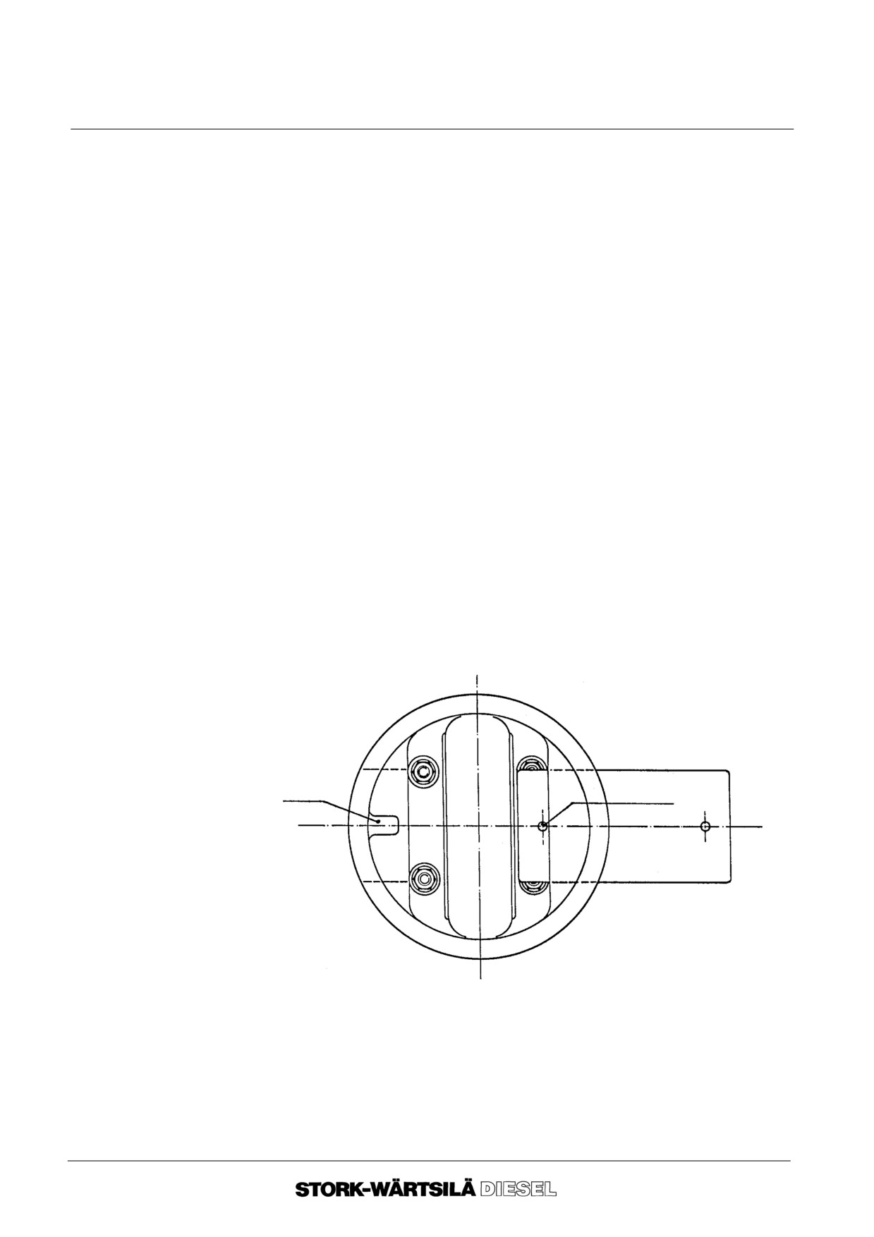
Take care that the connecting rod has the correct position with respect to the
protrusion in the piston skirt.
Looking at the cylinder number of the connecting rod, the protrusion must be on the
left--hand side.
Carefully lower the connecting rod until it just rests on the gudgeon pin and push
the gudgeon pin further until it touches the circlip.
Protrusion
Oil channel
7. Fit the second circlip in the same way as the first one.
8. Check the connecting rod for movement in the axial direction.
--o--o--o--o--o--
Ver. 01
16 -- 13
Manual
F 240
PISTON AND CONNECTING ROD
16H REMOVAL OF PISTON RINGS
Before starting work, please consult:
-- chapter 2, ”BACKGROUND INFORMATION” ;
-- chapter 3, ”TECHNICAL DATA” .
Tool C
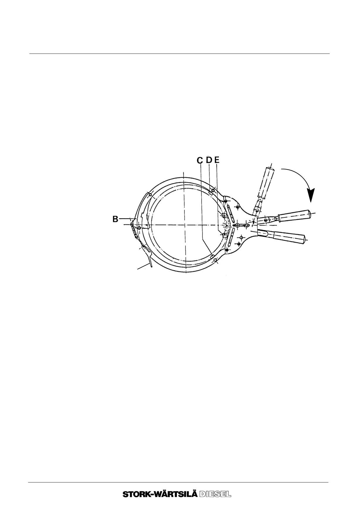
1. Removing piston rings:
1. 1. Release the spring tension of supporting plate B by means of lever A. Push
supporting plate B against the inner rim of the piston ring pliers by hand.
Place the piston ring pliers around the piston ring with protrusions E into the
gap.
F
A
1. 2. Tension supporting plate B by means of lever A.
1. 3. Tension the piston ring pliers by moving the handle F inwards.
1. 4. Remove the piston ring.
For inspection of parts, consult chapter 3, ”Technical data” ((No--Go criteria).
2. Attention!
It is only allowed to re--fit piston rings that have been removed with the piston ring
pliers.
--o--o--o--o--o--
Ver. 01
16 -- 14
Manual
F 240
PISTON AND CONNECTING ROD
16J FITTING OF PISTON RINGS
Before starting work, please consult:
-- chapter 2, ”BACKGROUND INFORMATION” ;
-- chapter 3, ”TECHNICAL DATA” .
1. Attention!
-- When renewing the piston rings the cylinder liner has to be honed.
-- Fit the piston rings in the correct order (see spare parts manual).
-- Fit the piston rings with the code numbers on topside.
-- The scraper ring consists of an outer ring and an inner spring.
Place first the inner spring in the piston ring groove and then the outer ring. The
gap of the scraper ring has to be fitted opposite the partition of the inner spring.
2. Carefully clean all parts.
Never use sharp or hard materials for cleaning the aluminium skirt!
Tool C
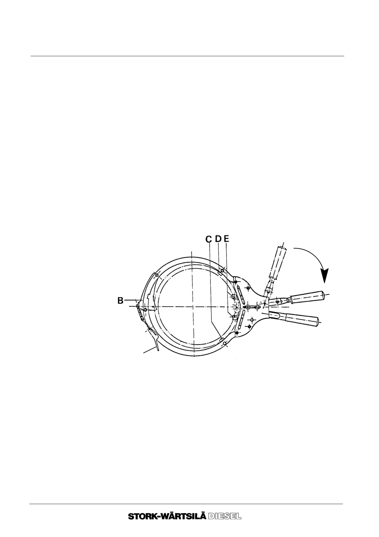
3. Fitting the piston rings:
3. 1. Tension supporting plate B by means of lever A.
F
A
3. 2. Place the piston ring on supporting points B, C and D with the protrusions E
between the gap of the piston ring.
3. 3. Tension the piston ring pliers by moving the handle F inwards and place the
piston ring into the piston ring groove. Release the tension by loosening
handle F and lever A.
Remove the piston ring pliers.
3. 4. Repeat this procedure for the other piston rings.
4. Position the piston rings, so that the gaps are about 180
from each other and
above the gudgeon pin bore.
--o--o--o--o--o--
Ver. 01
16 -- 15
Manual
F 240
PISTON AND CONNECTING ROD
16K FITTING PISTON AND CONNECTING ROD
Before starting work, please consult:
-- chapter 2, ”BACKGROUND INFORMATION” ;
-- chapter 3, ”TECHNICAL DATA”.
1.
Clean all parts thoroughly.
Whilst cleaning the piston, do not use sharp or hard tools. Make sure that the four oil
passages situated under the oil scraper ring are clean. These are used to discharge oil
to the inside of the piston.
Tool A
2.
Hoisting the piston with connecting rod into the engine:
2.
1.
Attach the hoisting ring A, to
the piston with the aid of two
fixing bolts. The eye bolt faces
A
must be level with the top of the
piston.
F
2.
2.
Hoist piston and connecting
rod above the cylinder liner.
Attention!
The connecting rods are
marked with the cylinder
number the numbering is
facing to the camshaft side.
2.
3.
Lubricate piston skirt and
piston rings sparingly with
clean engine oil.
G
2.
4.
Check that the gaps in the
D
piston rings are still in the same
position.
E
2.
5.
Position the clamping
ring, F.
B
With the lips pointed to the
gudgeon pin side. The lips
serve to hold the assembly in
place on the cylinder liner.
2.
6.
Fit the upper bearing shell into the connecting rod foot. The upper bearing shell
is the one with no oil groove.
Check that the bearing shell position lug is in its slot at the connecting rod foot
recess.
Place two holding plugs, item 8, diagonally opposite each other in the
connecting rod foot to prevent the bearing shell from falling out.
2. 7.
Hoist the piston and connecting rod assembly into the liner till the gudgeon pin.
Make sure the connecting rod cylinder number is facing the camshaft side.
2. 8.
Remove the protection from the crank pin and clean the crank pin.
2. 9.
Lubricate the crankpin sparingly with clean lube oil.
2.
10.Turn the crankshaft to Top Dead Centre.
Ver. 01
16 -- 16
Manual
F 240
PISTON AND CONNECTING ROD
16K FITTING PISTON AND CONNECTING ROD
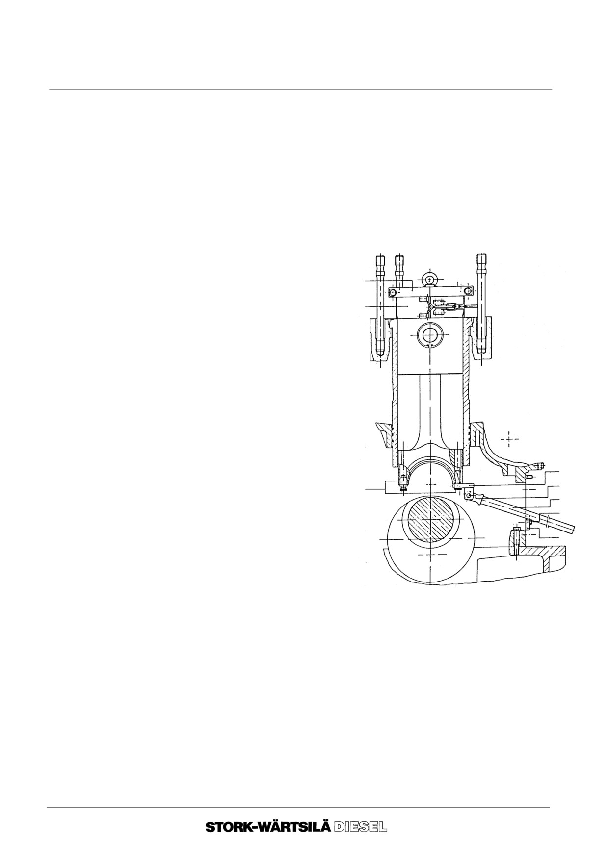
Tool A
3.
Fitting the connecting rod:
3. 1. Fit the support strip B, to the cylinder block using the bolts.
3. 2. Lower the piston and connecting rod until the hoisting ring comes to rest on the
piston ring strap clamp.
3. 3. Position the holder G, with lever E, in the connecting rod foot.
3. 4. Now move the weight of the connecting rod assembly onto the holder and lever.
3. 5. Slacken one of the hoisting ring fixing bolts slightly and lower the assembly it
rests on the crank pin journal.
3. 6. Check that the upper bearing shell beds down properly on the crank pin and that
the positioning lug of the bearing engages with the slot.
3. 7. Remove the holding down plugs from the connecting rod foot.
3. 8. Fit the connecting rod cap. For instructions see section 16D.
3. 9. Remove the support strip.
4.
Fit the cylinder head. See section 18C.
5.
Pre--lubricate the engine and check if the connecting rod and gudgeon pin bearing
is getting oil.
6.
Fit the crankcase covers.
--o--o--o--o--o--
Ver. 01
16 -- 17
Manual
F 240
PISTON AND CONNECTING ROD
16K FITTING PISTON AND CONNECTING ROD
Ver. 01
16 -- 18
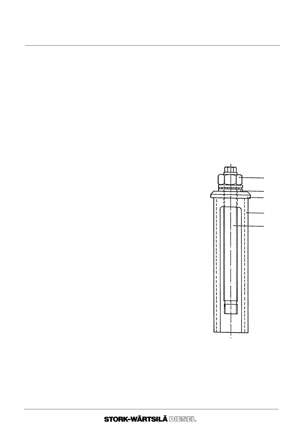
Manual
F 240
FUEL INJECTOR
17A NECESSARY TOOLS
Tool A
Removing of the fuel injector Tool Nr 9612 F 916
------------------------------------------------------------------------------------------------------------------------------------
Item No.
Description
Tool No.
Qty
------------------------------------------------------------------------------------------------------------------------------------
1.
PIPE
9612 F 161
1
2.
RING
9612 F 162
1
3.
BOLT
9612 F 163
1
4.
PRESSURE BEARING
9612 F 212
1
5.
NUT
9612 F 169
1
5
4
2
1
3
Ver. 01
17 -- 1
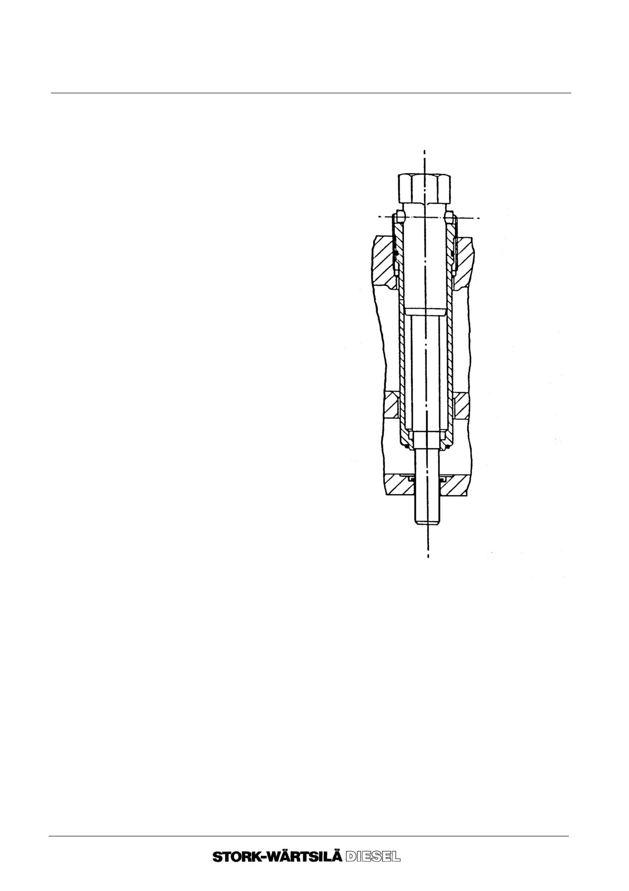
Manual
F 240
FUEL INJECTOR
17A NECESSARY TOOLS
Tool B
9612 F 013
Spanner for nozzle holder bush.
Tool code :
Ver. 01
17 -- 2
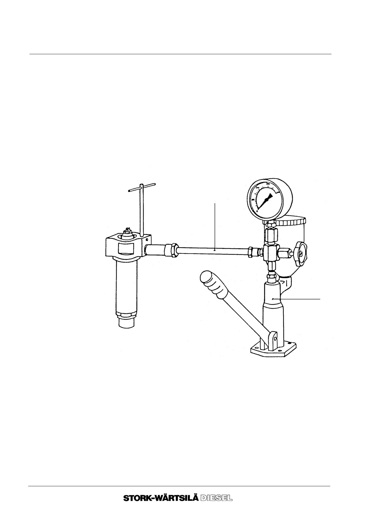
Manual
F 240
FUEL INJECTOR
17A NECESSARY TOOLS
Tool C
9612F908A Test pump used to test fuel injectors.
------------------------------------------------------------------------------------------------------------------------------------
Item No.
Description
Tool No.
Qty
------------------------------------------------------------------------------------------------------------------------------------
1.
Test pump
9612 F 139
1
2.
Fuel delivery pipe
9612 F 140
1
2
1
Ver. 01
17 -- 3
Manual
F 240
FUEL INJECTOR
17A NECESSARY TOOLS
Tool D
Special socket for tightening of the nozzle holder nut.
Tool code : 66542--0011
Ver. 01
17 -- 4
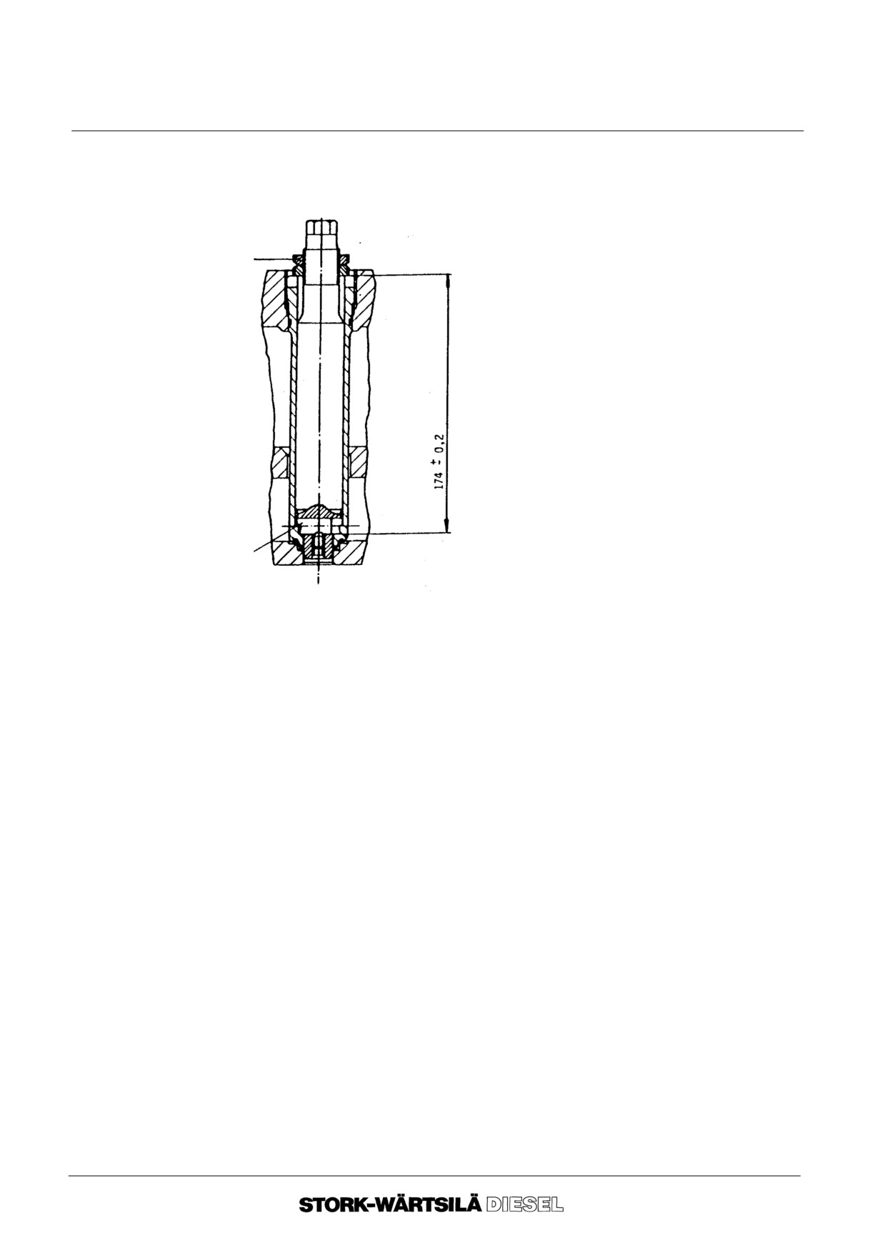
Manual
F 240
FUEL INJECTOR
17A NECESSARY TOOLS
Tool E
Boring tool for the removal of jammed sealing rings from under fuel injectors.
Tool number: 9612 F 014
--o--o--o--o--o--
Ver. 01
17 -- 5
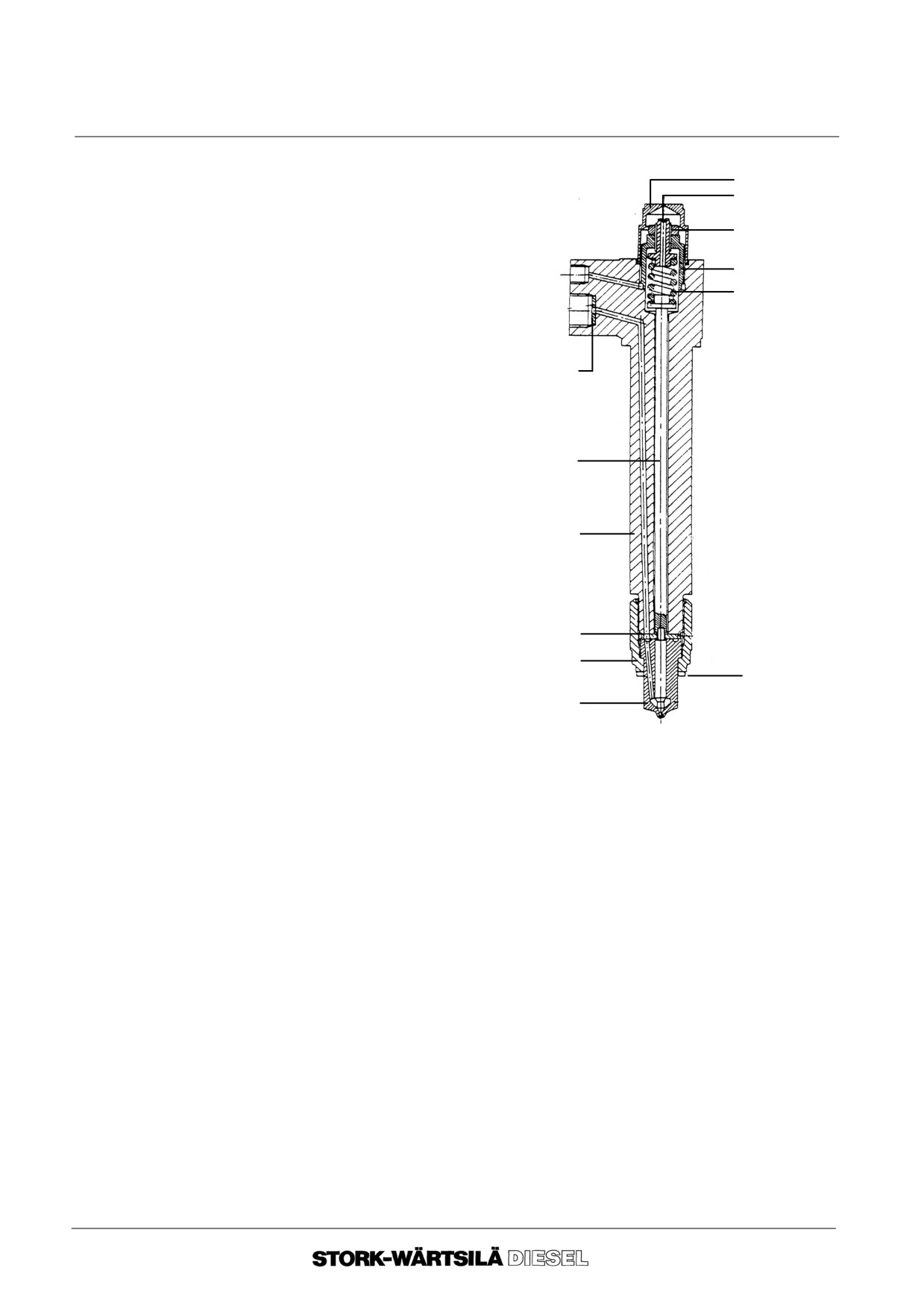
Manual
F 240
FUEL INJECTOR
17B REMOVAL
Before starting work, please consult:
11
-- chapter 2, ” BACKGROUND INFORMATION” ;
10
-- chapter 3, ”TECHNICAL DATA”.
9
Fuel Injector
8
7
The fuel injector consists of:
1
Nozzle
2
Sleeve nut
3
Wearing plate
4
Nozzle holder
6
5
Pressure rod
6
Joint washer (steel)
7
Pressure spring
8
Spring holder
9
Locking nut
5
10
Set screw with spring disc
11
Cap nut
12
Joint washer (copper)
4
3
2
12
1
7. Remove the clamp and disconnect the high pressure fuel line from the fuel pump,
and the vent line at the connection next to the fuel pump.
8. Withdraw the nozzle holder assembly by lifting it out perpendicularly, bringing the
high pressure fuel line and the vent line with it.
8. 1. Note:
If the nozzle holder cannot be removed easily because a carbon deposit
causes it to stick, than the use of the ’puller’, Tool A, is called for.
In this case, proceed as follows :
Remove the cap nut, spring holder, pressure spring and pressure rod.
8. 2. When removing the spring holder make sure not to slacken the locking nut
fitted on the spring holder, because this will cause derangement of the
injection pressure.
-- Fit the ’puller’.
-- Using a maximum torque of 500Nm (360 lbft), pull the nozzle holder out of
the cylinder head.
Ver. 01
17 -- 6
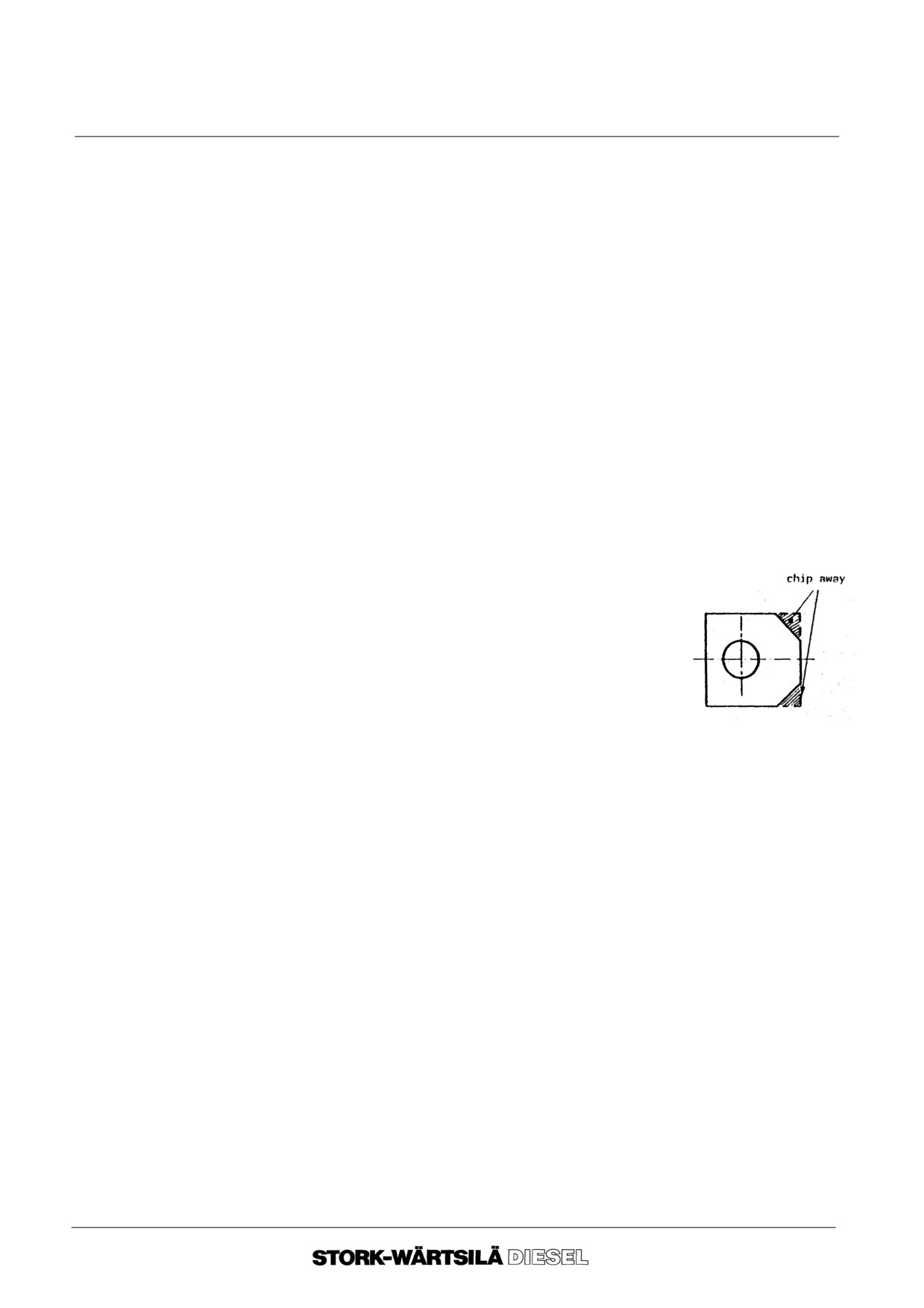
Manual
F 240
FUEL INJECTOR
17B REMOVAL
8. 3. Never try to lever the nozzle holder assembly loose with the aid of the high
pressure fuel line, as this may result in the nozzle holder bush rotating
slightly, so that it loses the correct tightening torque. This will increase the
risk of cooling water leakage into the combustion chamber.
It could also, and almost more likely so, damage the high pressure fuel line,
which is extremely dangerous, as the fuel inside is under enormous
pressure, when the engine is running.
To minimize the risk of leakage it must be standard procedure, immediately after
removal of the nozzle holder assembly, to check whether the nozzle holder sleeve still
has the required tightening torque by means of tool B.
It must be emphasised that the check must not be carried out by slackening the holder
sleeve first, but by tightening it at once to the correct torque.
Removal
If it proves impossible to withdraw the nozzle holder assembly with the help of the
procedure when
’puller’, the following solutions are available :
injector sticks
1. Fit a spare cylinder head, or
2.
--
Draw off the cooling water
--
Remove the fuel pipe connection from the nozzle holder
--
Chip away the corner tips (see sketch) to enable to
remove the nozzle holder. Otherwise the holder is
blocked by the guide pin of the valves.
--
Remove the nozzle holder along with nozzle holder bush.
--o--o--o--o--o--
Ver. 01
17 -- 7
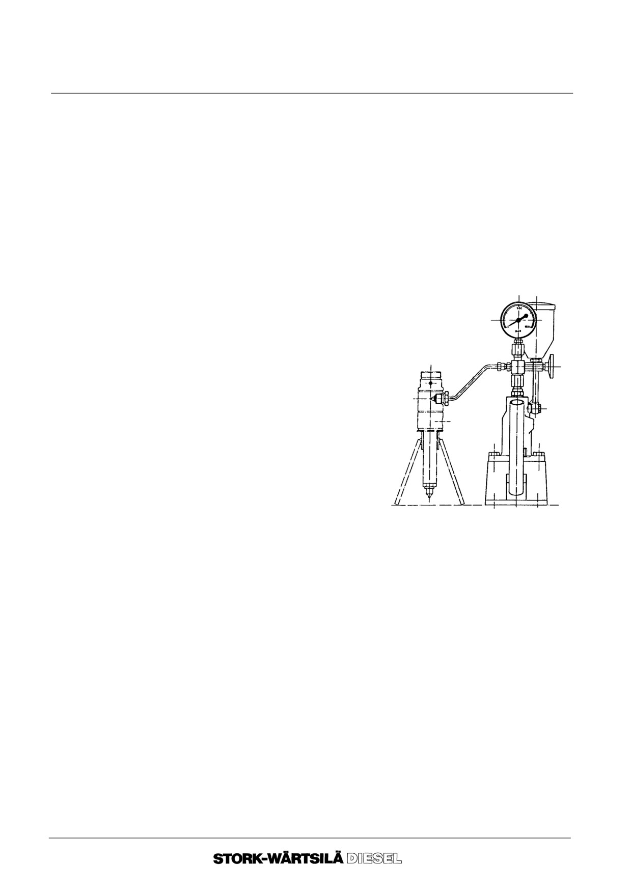
Manual
F 240
FUEL INJECTOR
17C CHECKING
Before starting work, please consult:
-- chapter 2, ” BACKGROUND INFORMATION” ;
-- chapter 3, ”TECHNICAL DATA”
1.
Connecting
Connecting the nozzle to the test pump (Tool C):
1. 1. Clean the fuel injector externally with pure gasoil.
If the fuel injector is out of use only during a very short time, gasoil can be
used tor testing. However, if the fuel injector is out of use during a prolonged
period of time, it is recommended that an oxidation--resistant calibration fluid
is used.
Even slight oxidation can cause the nozzle needle to stick.
1. 2. Connect the fuel injector to the
test pump.
Check that the tank is full of
clean gas oil or calibration fluid.
1. 3. Close the valve of the
manometer and pump the fuel
injector through with a few
strong strokes.
In this way all important parts will
come into contact with the test oil.
2.
Checking of the
Open the valve of the manometer a
opening pressure
quarter turn. Push the lever of the test
pump slowly downwards and slowly bring
the fuel to a pressure where the nozzle
opens.
Note the opening pressure of the nozzle.
For values of the opening pressure, see
chapter 3 Technical Data.
If the opening pressure is lower or higher
than the prescribed pressure, see section
17F.
3.
Checking needle
Open the valve of the manometer. Thoroughly dry the underside of the nozzle tip.
seal
Slowly bring the nozzle to a pressure, which is 10% lower than the pressure mentioned
in chapter 3 Technical Data.
The nozzle needle is completely closed, when no drop is formed on the nozzle tip
within 10 seconds.
Make sure that during testing no oil leaks along the side of the fuel injector!
4.
Checking fuel jet
Avoid putting your hands in the fuel jet!
Close the valve of the manometer.
Push the lever downwards once, with a short quick movement.
The fuel jets must be finely atomized, in equal form, under the same angle and equally
divided over the circumference!
The fuel jet can be checked by placing a piece of paper under the nozzle tip at a
distance of about 10 mm.
Ver. 01
17 -- 8
Manual
F 240
FUEL INJECTOR
17C CHECKING
5. Test results
If deviations were found in tests 2 to 4 the nozzle must be cleaned internally and test
repeated.
For disassembly see section 17D. For assembly see section 17E.
If there are still any deviations, renew the nozzle.
--o--o--o--o--o--
Ver. 01
17 -- 9
Manual
F 240
FUEL INJECTOR
17D DISASSEMBLY AND TESTING OF NOZZLE
Before starting work, please consult:
-- chapter 2, ”BACKGROUND INFORMATION” ;
-- chapter 3, ”TECHNICAL DATA”.
1.
Disassembly
1. 1. Clean the nozzle holder externally using clean gasoil.
1. 2. Reliese the nozzle holder spring and remove it.
1. 3. Remove the nozzle tip.
1. 4. Clean the removed parts internally and externally using clean gasoil.
2.
Nozzle inspection
When inspecting nozzles pay attention to :
--
wear of needle valve seat ;
--
needle lift ;
--
damaged needle tips ;
--
burning (discolouration) of the needle.
3.
Sliding test
This test should be performed on both used and new nozzles. Immerse the cleaned
nozzle needle and nozzle tip in clean gasoil or calibration fluid. When testing used
nozzles place the needle in the tip. Move the needle up and down a couple of times. Hold
the nozzle tip with needle vertically and using the hand, pull the needle out of its guide
up to 1/3 of its total length. Next release the needle, which should then slide back into
its seat by its own weight.
Note :
If any faults are found, (points 2 and 3), the nozzle must be replaced.
4.
Inspection of
When inspecting the nozzle holder pay attention to the following points :
nozzle holder
--
Damage to wearing plate caused by needle hammer. The wearing plate limits the
lift of the nozzle needle. When the plate surface becomes irregular as a result of
needle hammer, this will affect the lift of the needle. The plate can be used on both
sides. It must be renewed when both the top and the reverse side have suffered
damage from the needle.
--
Fracture of nozzle holder spring.
The nozzle holder spring may fracture and the coil ends may chip off through
vibration of maladjusted nozzles or the presence of water in the fuel.
--o--o--o--o--o--
Ver. 01
17 -- 10
Manual
F 240
FUEL INJECTOR
17E ASSEMBLY OF NOZZLE
Before starting work, please consult:
-- chapter 2, ”BACKGROUND INFORMATION” ;
-- chapter 3, ”TECHNICAL DATA”.
1. Clean the various components of the fuel injector with clean gas oil.
If new nozzles have been delivered, flush them through with clean gas oil.
2. Screw sleeve nut on to the nozzle holder by hand, making sure that the nozzle is
properly centred in the sleeve nut. Tighten the sleeve nut with the tightening torque
specified in chapter 3, Technical Data.
3. Complete the injector with the items mentioned in 17B.
--o--o--o--o--o--
Ver. 01
17 -- 11
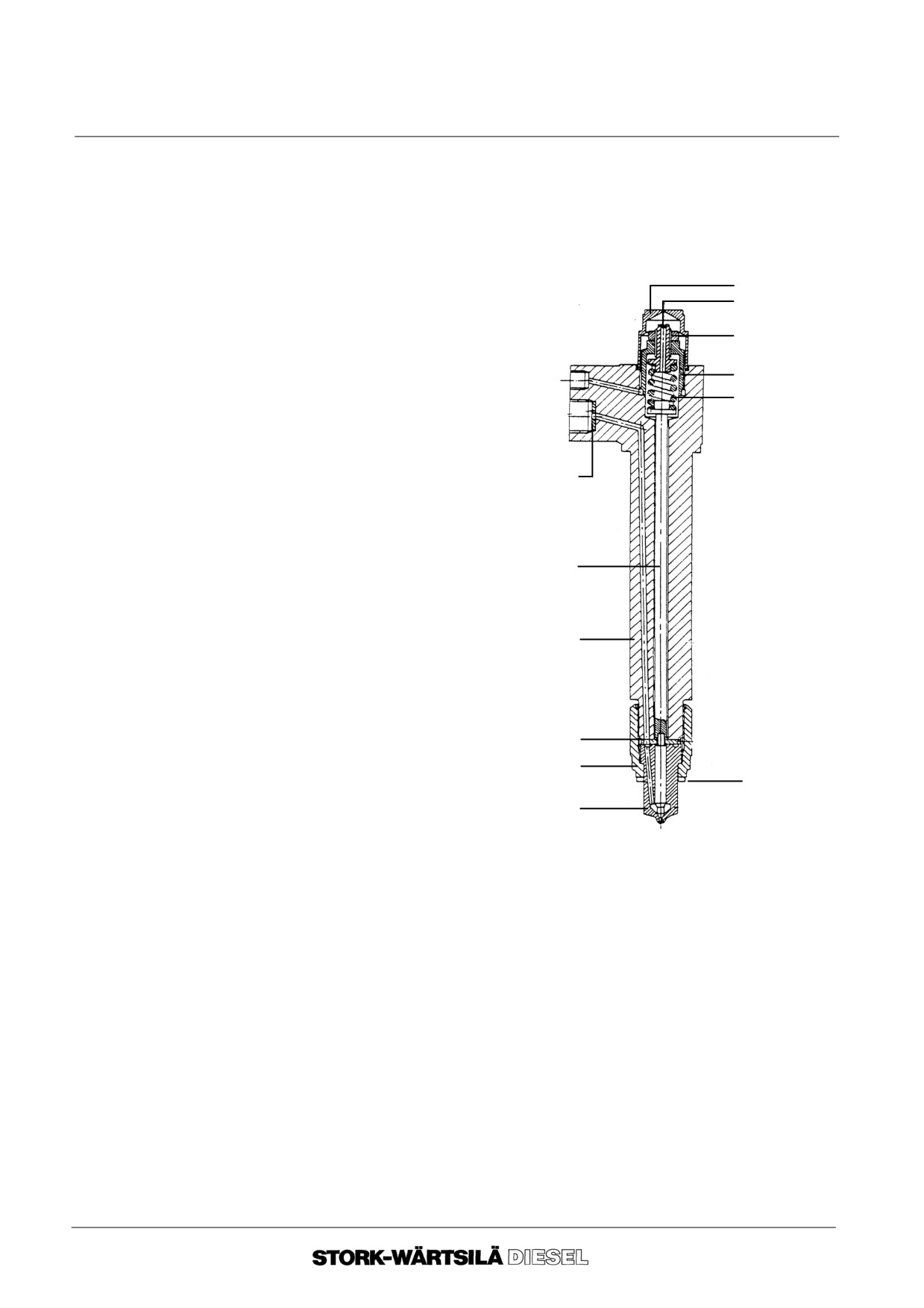
Manual
F 240
FUEL INJECTOR
17F SETTING OPENING PRESSURE
Before starting work, please consult:
-- chapter 2, ”BACKGROUND INFORMATION” ;
-- chapter 3, ”TECHNICAL DATA” .
For the required opening pressure, see
chapter 3 Technical Data. The proper
11
opening pressure can be brought
10
gradually up by means of the set screw
(10), while working the test pump
9
continuously.
After the correct setting with the set
8
screw, secure it with the locking nut (9).
7
And check the opening pressure again.
6
5
4
3
2
12
1
ALWAYS KEEP HAND ETC. AWAY FROM THE FUEL SPRAYS.
--o--o--o--o--o--
Ver. 01
17 -- 12
Manual
F 240
FUEL INJECTOR
17G REFITTING
Before starting work, please consult:
-- chapter 2, ”BACKGROUND INFORMATION” ;
-- chapter 3, ”TECHNICAL DATA”.
If the copper ring in the nozzle holder sleeve is jammed, it can be removed with a boring
tool, tool E. Boring may be effected with the aid of stop nuts, adjusted to the correct
dimensions beforehand.
During the boring operation the tool must be lubricated with grease at regular intervals.
Each time the tool is withdrawn the cuttings will remain trapped in the grease.
Always remove these cuttings before applying the tool again.
If, during the boring operation, the copper ring is found to rotate, a light tap on the top
end will be sufficient to make the tool penetrate the material, after which the ring should
be bored out without difficulty.
Fitting of injector
1. Fit the high pressure fuel line in to the nozzle holder so that the high pressure fuel
into cylinder
line runs parallel to the nozzle holders cylindrical part.
head
2. Tighten the union nut of the high pressure fuel line to the torque specified in the
Technical Data.
3. Fit the nozzle holder with a new copper sealing ring and O--ring in top. Place the
nozzle holder in the bush. Make sure the cone of the high pressure fuel line
engages fully with the fuel pump connecting.
4. Tighten the other union nut to the same torque.
5. Tighten the nut on the nozzle holder clamp to the torque specified in Technical
Data.
--o--o--o--o--o--
Ver. 01
17 -- 13
Manual
F 240
FUEL INJECTOR
17G REFITTING
Ver. 01
17 -- 14
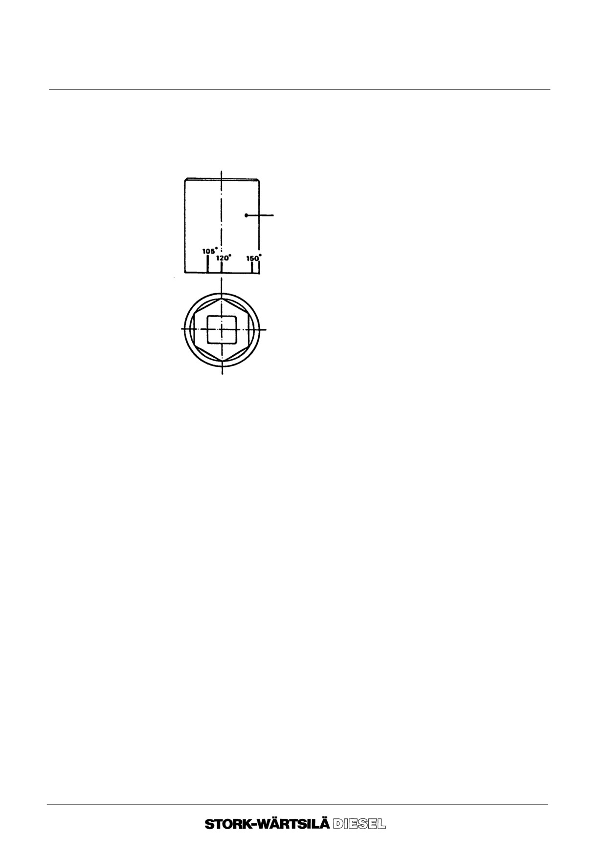
Manual
F 240
CYLINDER HEAD
18A NECESSARY TOOLS
Tool A
Socket spanner for cylinder head. Around the base of this socket, angles have been
marked to indicate the angular displacement of the cylinder head nuts.
Tool number : 9612F235
Ver. 01
18 -- 1
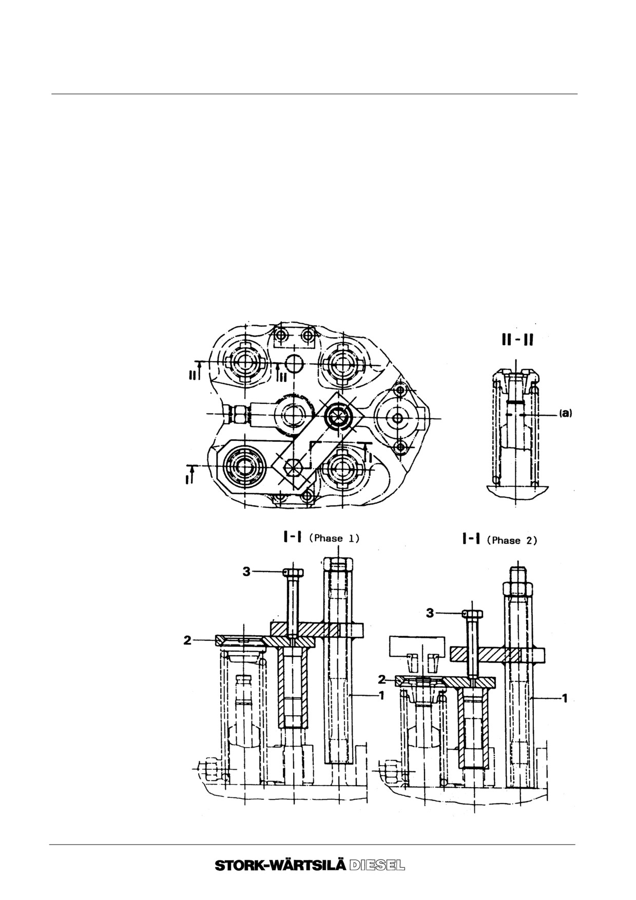
Manual
F 240
CYLINDER HEAD
18A NECESSARY TOOLS
Tool B
Tools assembly/disassembly valve spring and/or valve.
Tool number : 9612 F 930.
Holding fixture, item 1. This is the fixture which bolts down over the injector clamp stud,
and is both used for the lifting of the cylinder head from the cylinder liner, and in order
to press down on the pressure pad.
Tool number : 9612F255
Pressure pad, item 2. This fits over the bridge piece guide pin and presses down on
the valve spring of any one valve.
Tool number : 9612F258.
Pressure bolt, item 3. This bolt screws into the threaded hole in the holding fixture,
and thereby presses down on the pressure pad.
Tool number : 9612F261
Ver. 01
18 -- 2
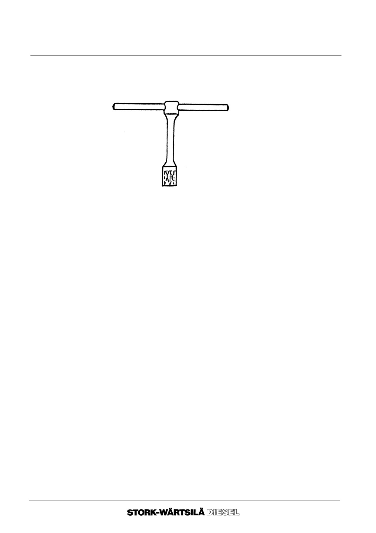
Manual
F 240
CYLINDER HEAD
18A NECESSARY TOOLS
Tool C
T--Wrench -- for undoing the indicator cocks on the cylinder heads.
Tool number : 7024 . 612
--o--o--o--o--o--
Ver. 01
18 -- 3
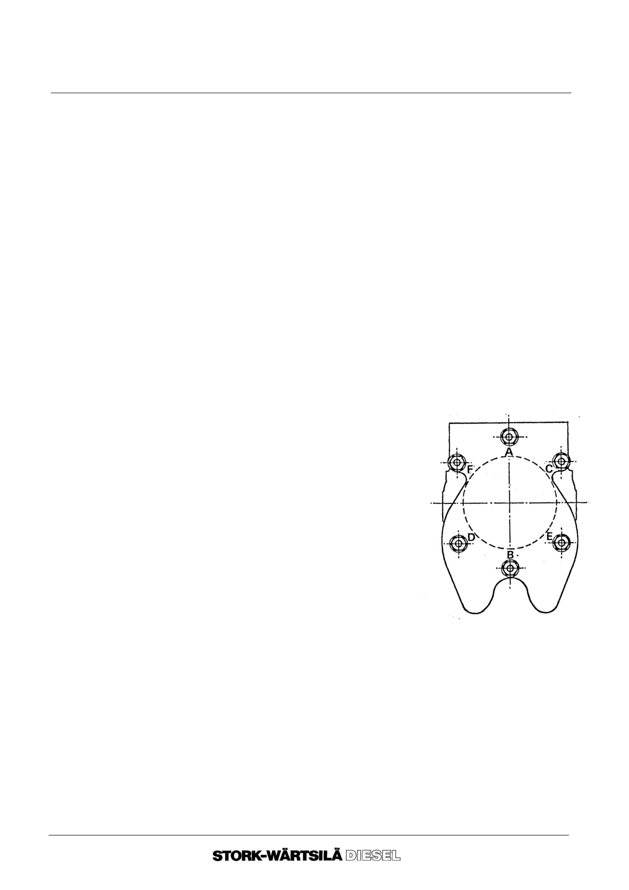
Manual
F 240
CYLINDER HEAD
18B REMOVAL
Before starting work, please consult:
-- chapter 2, ”BACKGROUND INFORMATION” ;
-- chapter 3, ”TECHNICAL DATA”.
1.
Drain the cooling water by removing the plug located in the cylinder block behind the
H.T. cooling water pump. The cooling water should be preferably be stored for
re--use.
2.
Remove the valve rocker covers and disconnect all pipes fitted to the cylinder head.
3.
Bar the engine over to the position where the inlet and exhaust valves of the cylinder
involved are closed, T.D.C. of the firing stroke.
4.
Removal of the cylinder head
4. 1. Remove the valve rockers, push rods, bridge pieces, and pyrometer, as well as
the nozzle holder clamp and the nozzle holder.
4. 2. After having removed the nozzle holder, always check to make sure the nozzle
holder bush is still tightened to the correct torque. When doing this, never first
undo the bush not even a little, as this will cause cooling water leakage into the
cylinder, just tighten it.
Tool A
5.
Loosening the cylinder head:
5. 1. Loosen the cylinder head stud nuts in two
stages, observing the sequence A, B, C, D, E
and F in both stages:
--
--60o
--
Loosen the bolts complete
Tool B
6.
Remove the cylinder head and be careful not to
damage the sealing faces.
Proceed as follows :
6. 1. Place the holding fixture for valve spring
positioning and removal over the stud for the
nozzle holder clamp and secure it with the nut.
6. 2. Attach a hoisting belt to the holding fixture and
carefully lift the cylinder head off the cylinder block.
--o--o--o--o--o--
Ver. 01
18 -- 4
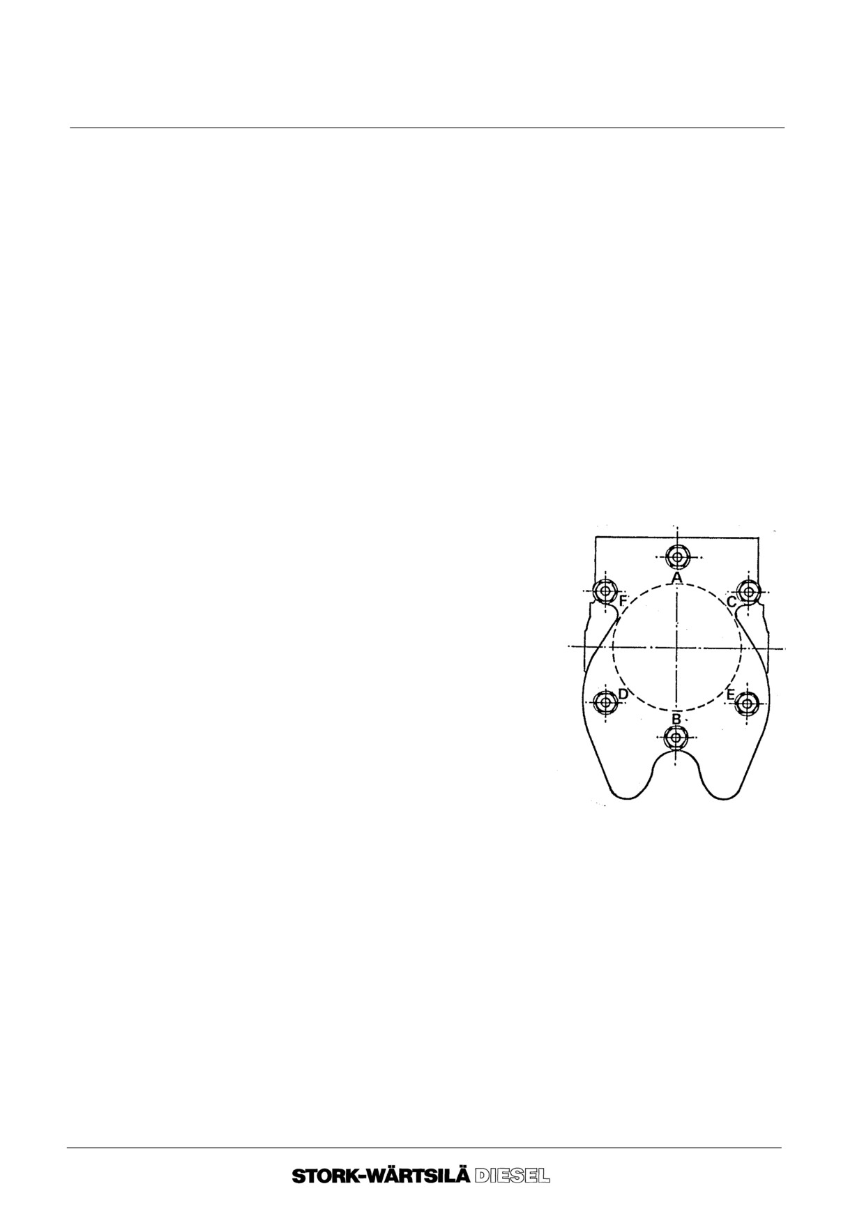
Manual
F 240
CYLINDER HEAD
18C FITTING
Before starting work, please consult:
-- chapter 2, ”BACKGROUND INFORMATION” ;
-- chapter 3, ”TECHNICAL DATA”.
1. Clean the sealing faces of the cylinder head and cylinder liner very thoroughly. If
necessary grind faces using a grinding ring.
2. Make sure all parts are in perfect condition.
3. Fit new gas sealing ring and new rubber ring. Do not oil or grease the gas sealing ring.
4. Fit V--ring seals around the cylinder head studs. These will prevent dirt and/or water
from entering the stud holes. There are 6 V--ring seals per cylinder.
Position locating rings (4 per cylinder) around the cylinder head studs C--D--E--F to
centre the cylinder head.
5. Place cylinder head gently on cylinder liner.
6. Clean the nuts, washers and contact faces
thoroughly and lubricate them sparingly with
oil.
7. Tighten the nuts by hand. Never restore the
screw thread on the studs with a thread cutting
die, as this thread is rolled, and cutting will
destroy it.
8. Secure the nuts as instructed under the
tightening procedure in the Technical Data.
9. Connect all pipes to the cylinder head.
10. Add cooling water up to the required level and
make sure this water is given the proper treatment.
11. Fit bridge pieces, valve rockers, push rods, nozzle holder and nozzle holder clamp.
The valve rockers need to be tightened to a torque specified in the Technical Data.
12. Adjust valve clearance, see 18G.
Remark:
The cylinder head studs under the dust cap have plastic caps on the nuts to prevent
oil leakage along the studs.
--o--o--o--o--o--
Ver. 01
18 -- 5
Manual
F 240
CYLINDER HEAD
18D VALVES
Before starting work, please consult:
-- chapter 2, ”BACKGROUND INFORMATION” ;
-- chapter 3, ”TECHNICAL DATA”.
1. Removal
1. 1. Remove cylinder head -- see section 18B.
1. 2. Remove valve springs -- see section 18E.
1. 3. Remove valve.
Note :
Make sure the valve keepers, spring cup, valve and spring clip of each valve
are kept together. The spring clips for inlet-- and exhaust valves are
different.Holding fixture, item 1. This is the fixture which bolts down over the
injector clamp stud, and is both used for the lifting of the cylinder head from
the cylinder liner, and in order to press down on the pressure pad.
Tool number : 9612F255
2. Inspection
2. 1. Check the clearance between valve stem and valve guide.
(This must be less than 0.20 mm over at least 3/4 of the valve guide length).
2. 2. Pay attention to the No Go dimension limits.
2. 3. Polish the valve stem top at the valve locking split cone using ”grain 360”
abrasive linen, until it is smooth.
2. 4. Examine the valve stem top and valve disc for
(hairline) cracks by
Magnafluxing (radial magnetisation). If any cracks are found, the valve must
be scrapped.
2. 5. Demagnetise the valve.
2. 6. Check the valve seat. Machine valve and valve seat if necessary.
2. 7. Clean the valve and the valve seat.
3. Fitting
3. 1. Place valve in position.
3. 2. Slide spring clip for exhaust valves in the groove of the valve stem. For the
inlet valves below the groove of the valve stem.
3. 3. Fit the valve springs -- see section 18F.
--o--o--o--o--o--
Ver. 01
18 -- 6
Manual
F 240
CYLINDER HEAD
18E VALVE SPRINGS
Before starting work, please consult:
-- chapter 2, ”BACKGROUND INFORMATION” ;
-- chapter 3, ”TECHNICAL DATA”.
1.
Removal
1.
1.
When only the valve springs need to be inspected or renewed, removal of the
cylinder head is not necessary.
1.
2.
Bar the engine over so that the piston involved reaches T.D.C. of the firing
stroke, with the valves closed.
1.
3.
Remove rocker arm assembly.
1.
4.
Withdraw the bridge piece. Remove the valve stem spring clip (this is only
necessary for inlet valves because here the spring cup cannot be slipped over
the clip).
Tool B
1.
5.
Push down the valve springs:
--
Place the pressure pad (2) on the free guide pin so that the hole in the pad
is in line with the bore of the spring cup.
--
Remove the nozzle holder clamp, if it is still in position.
--
Place the holding fixture (1) with bolt (3) on the stud thus released, and using
the stud nut tighten these down to the cylinder head face.
Note:
If inlet valves are being removed, first slide the spring clip around the valve
stem downwards, because the valve, the spring, the cup and or the clip could
be damaged.
--
Using the pressure bolt force the valve springs down so that the valve
keepers are released and can be taken out.
Note :
The valve keepers, spring cup and valve should be kept together for each
valve to preserve the proper match.
--
Remove the tools and withdraw the valve springs for inspection and/or
renewal.
2. Inspecting the
Examine the springs for :
valve springs
--
Hairline cracks ;
--
Squareness ;
--
Length.
Ver. 01
18 -- 7
Manual
F 240
CYLINDER HEAD
18E VALVE SPRINGS
3.
Fittting
3.
1.
Clean all parts thoroughly.
3.
2.
Refit parts in the reverse order after inspection and/or renewal of the valve
spring.
Note :
On inlet valves it is impossible to slip the spring cup over the spring clip. In
this case the valve spring must be positioned before the spring clip can be
slide around the stem and into its groove.
The best way of accomplishing this is as follows :
-- Before fitting the valve spring, slide the spring clip around the inlet valve
stem so that it is just below its groove.
-- Fit the valve spring, spring cup and valve keepers.
-- Using a screw driver to push the spring clip upwards into its groove
-- Make sure the spring clip is snug around the valve stem.
3.
3.
Position the cylinder head so that the valve can move freely.
3.
4.
Fit the valve keepers in place making sure that the space between the two
halves is evenly divided.
3.
5.
Place a piece of pounding copper (diam. 15 -- 18 mm) on the valve stem and
strike this a couple of times with a hammer, (approx. 0.7 kg), so that the valve
keepers can bed in.
--o--o--o--o--o--
Ver. 01
18 -- 8
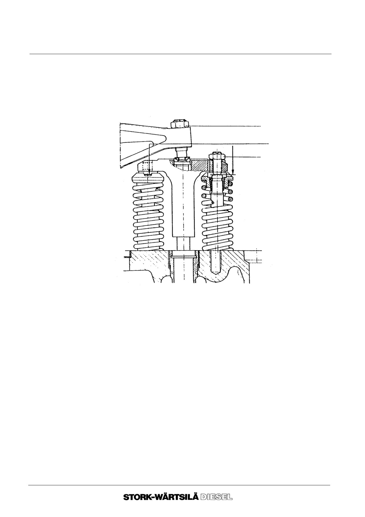
Manual
F 240
CYLINDER HEAD
18F ADJUSTMENT OF VALVE CLEARANCE
1. General
Proper adjustment of the valve clearance will prolong the life of the valves and the
valve seats.
A correct valve clearance gives the various components of the valve lift mechanism
sufficient space to expand with increasing material temperatures. Hence, the
clearance can only be checked and corrected when the engine components have the
same temperature. The clearances are the same for both inlet and exhaust valves.
A
feeler gauges
B
2. Adjustment
Before starting work, please consult:
procedure
-- chapter 2 -- BACKGROUND INFORMATION ;
-- chapter 3 -- TECHNICAL DATA.
2. 1. Remove the valve cover.
2. 2. Turn the piston in TDC in the firing stroke, there is no load on the valve
springs and the pushrods.
2. 3. Loosen locking nut (A) of the adjustable pivot in the valve lever and loosen
the adjustable pivot a few turns.
2. 4. If present, remove the oil film between the pivots by tapping a few times with
a plastic hammer on the ends of the valve levers.
2. 5. Place two feeler gauges of equal thickness, as mentioned in chapter 3 --
technical data -- between the pivots under the bridge piece and the upper
surface of the valve stems.
Ver. 01
18 -- 9
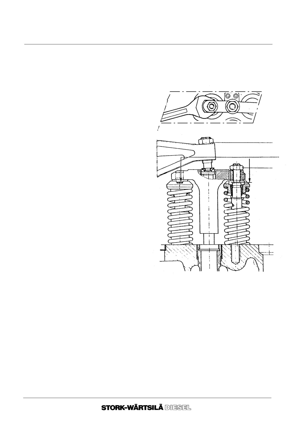
Manual
F 240
CYLINDER HEAD
18F ADJUSTMENT OF VALVE CLEARANCE
2.
6. Loosen locking nut (B) of the adjustable pivot in the bridge piece and block the
bridge piece using a spanner.
This to prevent the bridge piece guide from being damaged.
2.
7. While exerting a
slight pressure on
the bridge piece turn
the adjustable pivot
in the bridge piece
until
the
slide
resistance of
both
feeler
gauges is
equal.
2.
8. Tighten locking nut
A
(B) by hand without
2 feeler gauges of same size
turning
the
adjustable pivot.
B
2.
9. Tighten locking nut
(B)
(main data)
--
further
without
turning
the
adjustable
pivot.
Block the bridge
piece by means of a
spanner.
2.
10.Again check the slide
resistance of the
feeling
gauges,
which has to be
equal.
2.
11. Turn down the
adjustable pivot of
the valve lever until
there is no more
clearance.
2.
12.Tighten locking nut (A) without turning the adjustable pivot.
2.
13.Again check, whether the slide resistance of both feeler gauges is the same.
2.
14.Remove the feeler gauges and repeat the procedure for the other pair of valves.
2.
15.Fit the valve cover.
--o--o--o--o--o--
Ver. 01
18 -- 10
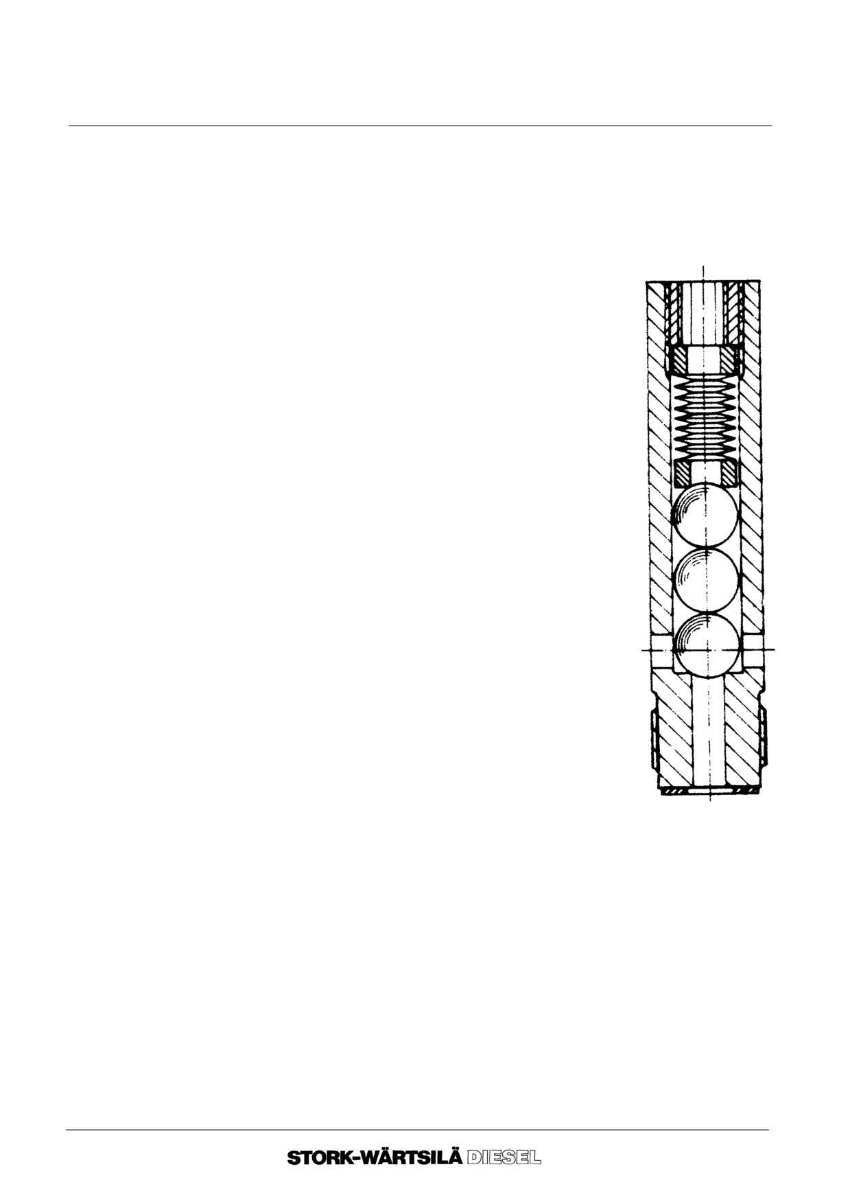
Manual
F 240
CYLINDER HEAD
18G CYLINDER HEAD SAFETY VALVE
Before starting work, please consult:
-- chapter 2, ”BACKGROUND INFORMATION” ;
-- chapter 3, ”TECHNICAL DATA”.
1.
Inspection
1.
1.
Remove the cylinder head safety valve from the
connecting piece.
1.
2.
Remove the connecting piece after screwing the
cap or, if available, the indicator cock from the
reducing nipple.
1.
3.
Withdraw the reducing nipple from the cylinder
head.
1.
4.
Check that the blow--off passage in the cylinder
head and the passages in the reducing nipple
and connecting piece are open.
1.
5.
Pressure--test the safety valve.
Note :
The pressure test can be performed by
connecting the safety valve to the nozzle test
pump with the aid of an adaptor. If the safety
valve leaks, the ball seat must be rectified, and
the balls renewed. It may also be necessary to
replace the disc springs.
1.
6.
Fit the safety valve in the connecting piece and
the reducing nipple in the cylinder head using
new sealing rings.
--o--o--o--o--o--
Ver. 01
18 -- 11
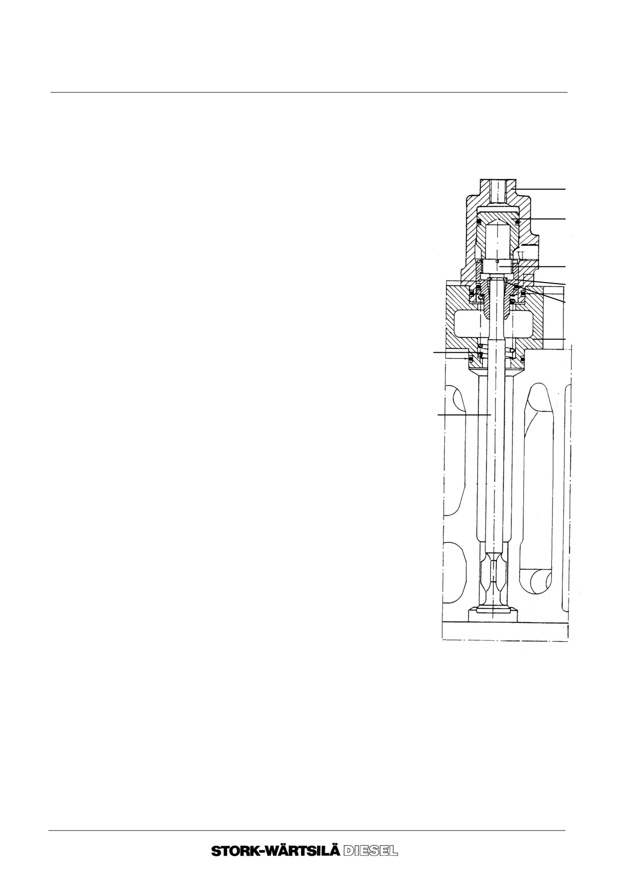
Manual
F 240
CYLINDER HEAD
18H STARTING AIR VALVE
Before starting work, please consult:
-- chapter 2, ”BACKGROUND INFORMATION” ;
-- chapter 3, ”TECHNICAL DATA”.
Before removing the starting air valve, the cylinder
head has to be removed., see chapter 18B.
A
B
1. Removal
1. 1. Remove plunger housing (A) with plunger
(B).
1. 2. Remove plug (C) by heating (loctite joint)
C
and by means of a screwdriver (threaded
joint).
D
E
1. 3. Force plunger (D) down in order remove the
valve keepers (E).
H
1. 4. Remove spring (F) and starting valve (G).
F
1. 5. Remove connecting piece (H) from cylinder
head.
G
2. Fitting
2. 1. Clean and inspect all parts thoroughly.
Lubricate the plungers with Molycote G.N.
2. 2. Fit connecting piece (H) with a new O--rings.
2. 3. Fit starting valve (G), spring (F) and plunger
(D) with a new O--ring.
2. 4. Fit the valve keepers (E).
2. 5. Fit plug (C) with a screwdriver and secure it
with Loctite.
2. 6. Fit plunger housing (A) with plunger (B) with
new O--rings.
--o--o--o--o--o--
Ver. 01
18 -- 12
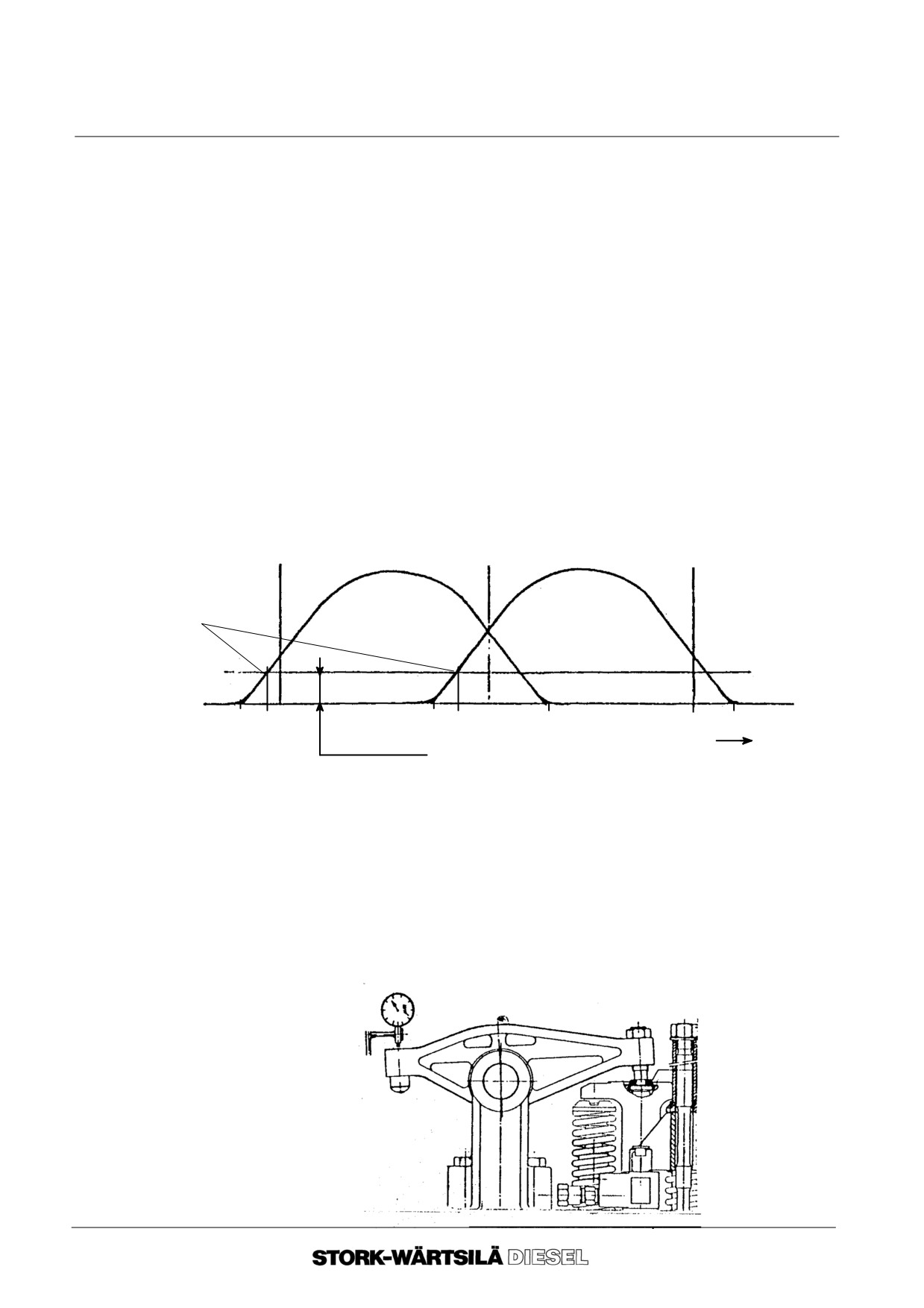
Manual
F 240
CAMSHAFT
19A CHECKING VALVE TIMING
Before starting work, please consult:
-- chapter 2, ”BACKGROUND INFORMATION” ;
-- chapter 3, ”TECHNICAL DATA”.
The inlet and exhaust valve timing can to be checked for instance after positioning the
camshaft. Valve diagram for the camshafts:
-- 2103 F 981A ;
--
”
”
982A ;
--
”
”
983A ;
--
”
”
984A ;
--
”
”
985A ;
--
”
”
986A.
3. Turn the crankshaft in the direction of rotation to neutralise the backlash, to Top
Dead Centre of the compression stroke of the corresponding cylinder. Make sure
that the valves are closed, so the push rods can be turned freely.
4. Set the valve clearance of the inlet and exhaust valves to 0 mm.
Bottom Dead Centre
Top Dead Centre
Bottom Dead Centre
Inlet cam
Exhaust cam
Checking points
2104 F 212
2104 F 212
51o
15o
55o19o
55o
51o
4.03 mm lifting
CRANK ANGLE
Exhaust valve
5. Measuring the cam lifting:
5. 1. Place the dial gauge on the exhaust rocker arm exactly above the pushrod.
5. 2. Set the dial gauge to 0 mm.
5. 3. Turn the engine in the direction of rotation until the dial gauge indicates
4.03 mm.
5. 4. Take a reading of the number of crank degrees. The value found has to be 15o
before Bottom dead centre, permitted tolerance is 1o.
Ver. 01
19 -- 1
Manual
F 240
CAMSHAFT
19A CHECKING VALVE TIMING
Inlet valve
6. Measuring the cam lifting:
6. 1. Place the dial gauge on the inlet rocker arm exactly above the pushrod.
6. 2. Set the dial gauge to 0 mm.
6. 3. Turn the engine in the direction of rotation until the dial gauge indicates 4.03
mm.
6. 4. Take a reading of the number of crank degrees. The value found has to be 19o
before Top Dead Centre, permitted tolerance is 1o).
7. If the setting is not correct please consult the Service Department of Stork
Wärtselä Diesel. If the setting of the cam is correct, adjust the valve clearance. The
setting values are specified in Technical Data.
--o--o--o--o--o--
Ver. 01
19 -- 2
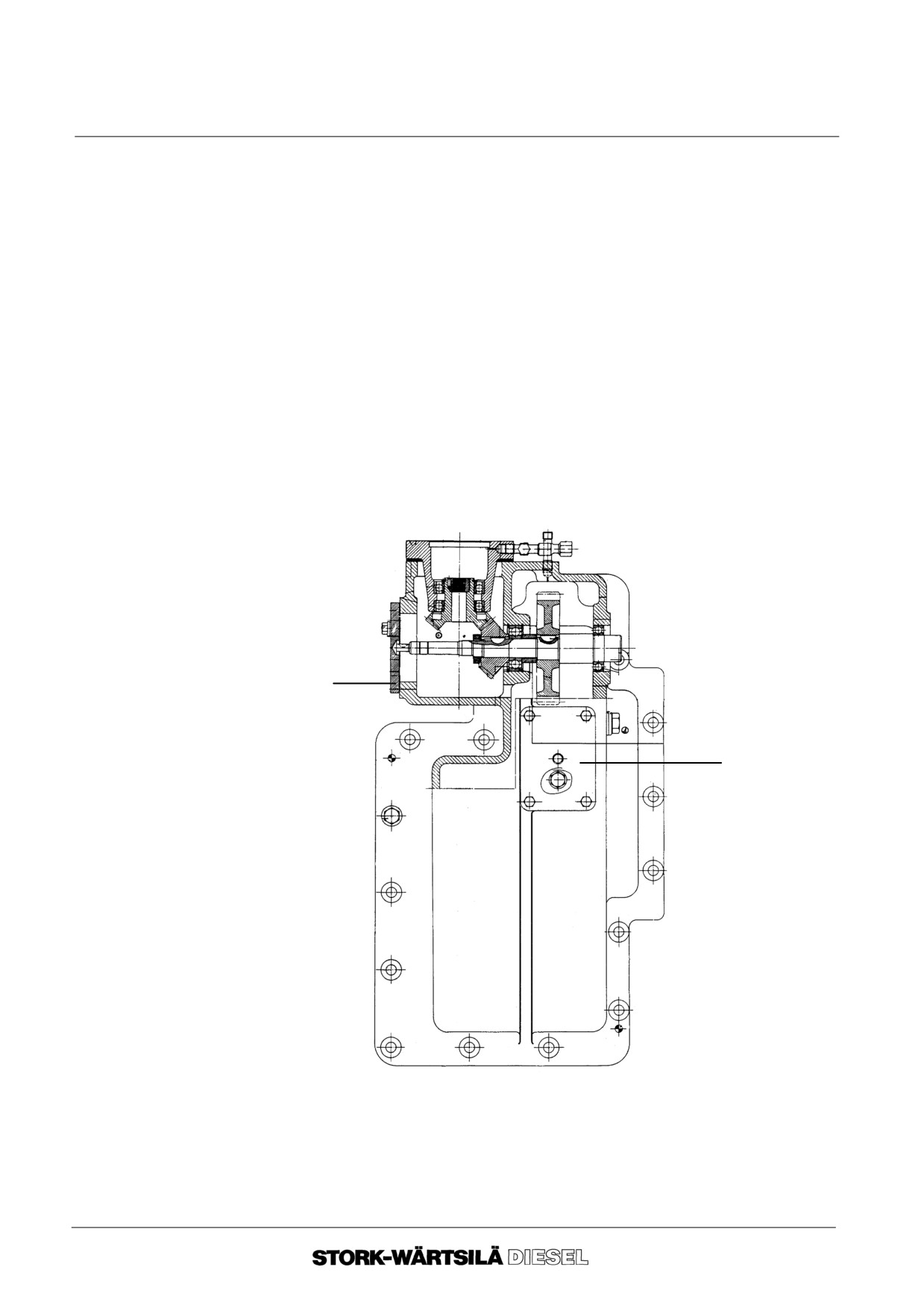
Manual
F 240
GOVERNOR
20A GOVERNOR DRIVE INSPECTION
Before starting work, please consult:
-- chapter 2, ”BACKGROUND INFORMATION” ;
-- chapter 3, ”TECHNICAL DATA” ;
-- SUB-- SUPPLIERS MANUALS.
1. Remove the end cover (A) of the governor drive and the gasket and inspect cover
(B) and the gasket.
2. Visually check the gear wheels of the governor drive on such aspects as meshing
pattern, pitting and any other damage, and check the backlash.
Attention!
In case of non--conformities, have necessary parts replaced.
3. Fit the end cover (A) of the governor drive, using a new gasket.
4. Fit the inspection cover (B) using a new gasket.
A
B
--o--o--o--o--o--
Ver. 01
20 -- 1
Manual
F 240
GOVERNOR
20B GOVERNOR ADJUSTMENT
Before starting work, please consult:
-- chapter 2, ”BACKGROUND INFORMATION” ;
-- chapter 3, ”TECHNICAL DATA” ;
-- SUB-- SUPPLIERS MANUALS.
1.
Compensation
Indicated by a needle outside the governor (min. -- 50% -- max.). For the correct value,
consult the test bed report.
Note :
When tightening the locking nut, hold the compensation needle in position.
2.
Compensation
The valve is located in the governor base, behind a plug. It includes two slots; a
needle valve
shallow slot for a screw driver, and a deep slot allowing the valve to be locked in
position. For the correct position consult the test bed report.
Note :
Normally the needle valve is1/2 to3/4 turn open.
Always adjust the needle valve with a cross-head screwdriver.
3.
Adjustment of the
Adjusting by full operational temperature.
governor after
overhaul
3. 1. Set the compensating needle to the minimum position. Open the needle
valve fully and then close it slowly until the governor stop hunting.
If the governor keeps hunting then :
3. 2. Move the compensating needle slightly towards the maximum position.
Open the needle valve fully and close it slowly until the governor stops
hunting.
3. 3. If the hunting continues, then repeat the procedure of su--section 2 and
check the needle valve position.
4.
Speed droop
The speed droop is the difference between the engine speed at full load and the engine
speed at zero load.
For Example:
Engine speed at full load 900 rpm
Engine speed at zero load 936 rpm.
The difference is 36 rpm, which amounts to a speed droop of 4%, which is normal.
The speed droop can be adjusted :
On governors type UG--8L (Lever control) internally,
On governors type UG--8 (Dial control) externally.
For detailed information see Sub--suppliers manuals.
--o--o--o--o--o--
Ver. 01
20 -- 2
Manual
F 240
GOVERNOR
20C INTERNAL CLEANING
Before starting work, please consult:
-- chapter 2, ”BACKGROUND INFORMATION” ;
-- chapter 3, ”TECHNICAL DATA” ;
-- SUB--SUPPLIERS MANUALS.
When the oil in the governor must be changed, proceed as follows :
1. Remove the drain plug from the governor base and drain the lubrication oil, when
the engine is hot.
2. Fill up the governor with a mixture of 50% gas oil and 50% lubrication oil.
3. Run the engine at a speed of approx. 500 rpm.
Note :
When the engine is being used to drive a generator, use the lowest acceptable rpm.
To this end, consult the generator manufacturer and / or the engine acceptance record.
4. Open the needle valve in the governor base a couple of turns. This will cause the
governor to hunt (i.e. work erratically).
5. Stop the engine after approximately 10 minutes.
6. Drain the mixture.
7. Fill up the governor with the required lubrication oil as specified by the governor
supplier.
8. Run the engine once more at approximately 500 rpm for 10 minutes.
9. Drain the lubrication oil.
10. Fill up the governor with the required lubrication oil.
11. The oil level must remain visible in the oil level glass.
12. Adjust the needle valve with a running engine at full operational temperatures.
See also section 20B.
--o--o--o--o--o--
Ver. 01
20 -- 3
Manual
F 240
GOVERNOR
20C INTERNAL CLEANING
Ver. 01
20 -- 4
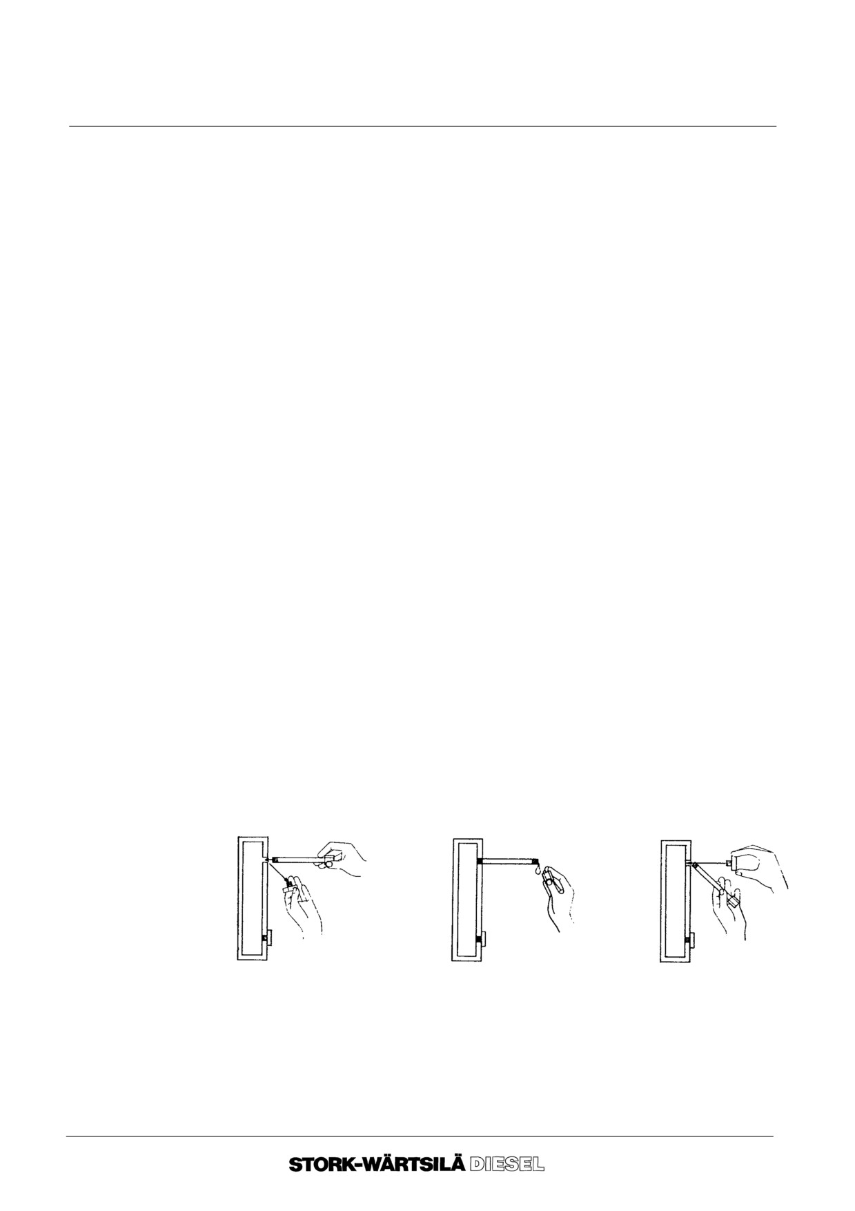
Manual
F 240
VIBRATION DAMPER
22A SAMPLING OF VISCOUS LIQUID
Before starting work, please consult:
-- chapter 2, ”BACKGROUND INFORMATION” ;
-- SUB-- SUPPLIERS MANUALS.
13. General
The vibration damper serves to reduce the torsional vibration produced by the
crankshaft. The damper consists of a housing and a freely rotating inertia ring
supported by an axial bearing. It forms a totally enclosed unit. The free space between
inertia ring and damper housing is filled with a high viscosity fluid. When the crankshaft
rotates at constant speed, the inertia ring will follow this movement. The combustion
pressure exerted on each piston causes vibration in the crankshaft, and each variation
produced by such a vibration will affect the movement of the inertia ring. The resulting
shift of the ring relative to the damper housing is opposed by the viscous fluid, so that
the vibration will be reduced.
The energy absorbed in the process is converted into heat and then given off to the
surrounding air. Hence proper ventilation of the damper is essential.
The damper cover has two filling holes located 180o opposite each other and closed
by screwed--in filler plugs. If one of these plugs is accessible, a fluid sample can be
drawn with the damper in place. On a dismounted damper, sampling must be effected
with the damper in the vertical position.
For liquid sampling, a special kit can be ordered from Stork--Wärtsilä Diesel.
14. Liquid sampling
To draw off the sample proceed as follows :
14. 1.Turn the engine until the two drain plugs are easy accessible, preferably in
vertical position.
Do not unscrew the drain plug until the damper is luke warm (approx. 40 C).
14. 2.Carefully tap the locking of the upper drain plug backwards, using a punch, and
unscrew the threaded plug. Do not yet remove the plug!
14. 3.Unscrew one cap nut from the (plastic) liquid container, the thread of which
corresponds to that of the drain plug in the damper. The ends of the liquid
container have various threads for other damper types.
14. 4.Remove the drain plug and screw the liquid container instead.
Fig. 27.1
14. 5.Remove the outer cap nut from the liquid container. Make sure that no machine
oil or dirt can enter the liquid container!
14. 6.Screw the outer cap nut again, once the liquid has reached the open end of the
liquid container.
The filling--up period of the liquid container may take from a few seconds
up to more than an hour, depending on the liquid condition.
Ver. 01
22 -- 1
Manual
F 240
VIBRATION DAMPER
22A SAMPLING OF VISCOUS LIQUID
14. 7.Unscrew the liquid container from the damper and fit the drain plug using a new
joint ring (supplied with the mounting kit).
14. 8.Fit the second cap on the liquid container.
If no sample can be taken in this way, you can proceed as follows:
-- If still no liquid appears after a while, remove the second drain plug, too.
-- Supply nitrogen of 3.5 bar maximum pressure through the open filling hole.
If no nitrogen is available, air may be used, provided this air is properly
filtered and dry.
-- Once the liquid has reached the open end of the liquid container, cut off the
supply of nitrogen and screw the cap on the liquid container.
-- After the nitrogen supply has been cut off, unscrew the liquid container,
screw the second cap and fit both drain plugs.
If a liquid sample cannot be obtained this way either, it can be assumed that the
damper liquid has thickened to an inadmissible value, necessitating the
replacement of the damper.
14. 9.Tighten the drain plugs to a torque of 35 Nm (25 lb.ft).
14.
10.
Lock the drain plugs by deforming the cover with a (centre) punch.
Replace any damaged drain plugs.
14.
11.
Remove the damper, if neither of the drain plugs in the damper is
accessible for sampling.
For sampling, place the removed damper in the VERTICAL position.
14.
12.
After the damper has been re--fitted, tighten the fastening bolts, to the
correct torque.
Please refer to chapter 3 -- TECHNICAL DATA (Tightening torques and jack
pressures).
14.
13.
After the sample has been taken and the cap nuts of the liquid container
have been properly tightened, provide the sample with a label (included in the
sampling kit) showing the following data :
-- serial number of the vibration damper
-- engine type
-- engine number
-- number of operating hours
-- date of sampling
-- application (name of the ship or plant)
-- Forward the sample to :
Stork--Wärtsilä Diesel
Postbox 10608
8000 GB Zwolle
Once we have examined the sample, the result will be reported to you in
writing; this report will also include recommendations.
14.
14.
No more than 10 liquid samples of 1 cm3 each are allowed to be taken.
--o--o--o--o--o--
Ver. 01
22 -- 2
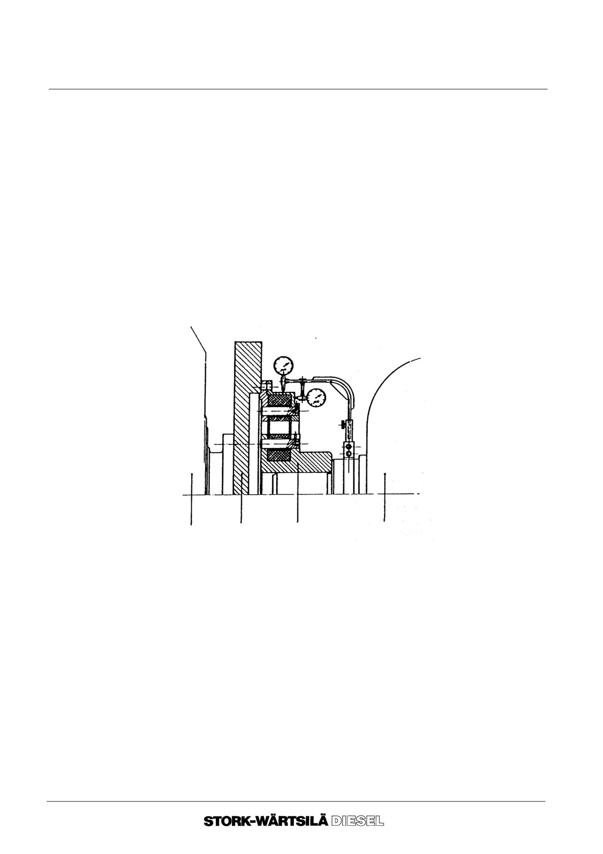
Manual
F 240
ENGINE ALIGNMENT
23A VERIFICATION
Before starting work, please consult:
-- chapter 2, ”BACKGROUND INFORMATION” ;
-- chapter 3, ”TECHNICAL DATA” ;
-- SUB-- SUPPLIERS MANUALS.
15. General
Alignment means that the centre line of the engine crankshaft is made to coincide with
the centre line of the driven shaft. It also involves adjustment of the flexible coupling
for parallelism and concentricity. Both alignment and adjustment must be carried out
with the utmost accuracy to prolong the life of the flexible coupling elements and to
prevent premature wear of the bearings mounted in the engine and in the driven
machine.
The use of a flexible coupling permits absorption of the slight residual deviations in
alignment and parallelism.
16. Verification of
engine alignment
16. 1.Remove the protection cover.
flywheel
driven machine
engine
flexible coupling
16. 2.Fit 2 dial gauges for axial and radial measurement on the shaft of the driven
machine by means of a sturdy bracket and place them against the angle
flanges of the flexible coupling. See figure.
16. 3.Set gauges on zero.
16. 4.Bar the engine over and read off the dial gauges every 90 degrees.
Attention !
If there are no special requirements as with flexible foundation the following counts:
--
The alignment needs no correction when axial and radial deviation together don‘t
exceeds 0.4 mm.
--
Both coupling halves have to turn simultanuosly while radial measuring.
--
The engine crankshaft and the shaft of the driven machine must be unable to move
axial when the engine is barred over for measurement of the axial deflection.
Ver. 01
23 -- 1
Manual
F 240
ENGINE ALIGNMENT
23A VERIFICATION
17. Foundation bolts
Check that all bolts have been tightened to the proper torque by means of a torque
spanner (do not slacken the bolts when checking). The correct torques are specified
by the sub--supplier.
18. Flexible
foundation
elements (if fitted)
Check the elements for :
--
Swelling (through chemical attack by fuel, lube oil and / or detergents) ;
--
Rupture ;
--
Damage.
Renew elements showing any of the above defects.
19. Verification in
The start--up record specifies the distances between shims and (common) bedplate.
height
These distances serve as reference values. Measure the actual distances and enter
them on a record of the type illustrated. Comparison with the reference values will then
show up any variation in height that may have occurred. In evaluating such height
variations, use must be made of the following guide-lines.
--
The difference in comparison between juxtaposed elements on one side (i.e.
camshaft side or exhaust side) may not exceed 1 mm.
--
The compression of a given element on one side may vary plus or minus 1 mm
from the average compression on that side.
Note :
If the set--up of the engine is altered, the crankshaft deflection, the alignment and
parallelism must be checked and if necassary, readjusted. Faulty alignment will lead
to excessive engine vibration. To prevent misalignment it is also advisable to inspect
the flexible elements visually from time to time.
See also section 23B.
--o--o--o--o--o--
Ver. 01
23 -- 2
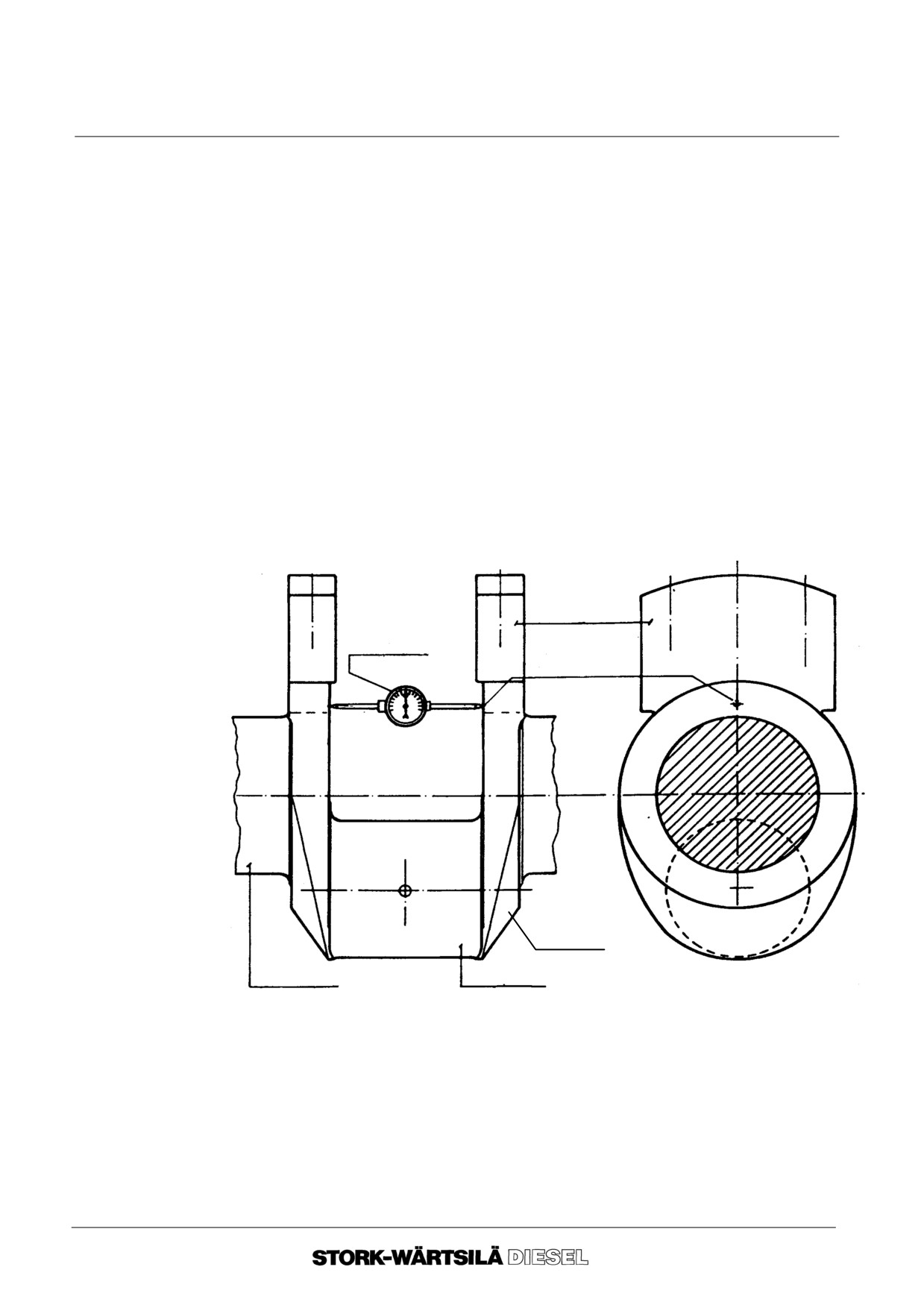
Manual
F 240
ENGINE ALIGNMENT
23B CRANKWEB DEFLECTION
Before starting work, please consult:
-- chapter 2, ”BACKGROUND INFORMATION” ;
-- chapter 3, ”TECHNICAL DATA” ;
-- SUB-- SUPPLIERS MANUALS.
1. Crankweb
The primary objective of crankweb deflection measurement is to check whether the
deflection
engine bearing bores are in line. The main bearings are machined so accurately that
the crankweb deflection is within 0.03 mm when the crankshaft is carrying no load (i.e.
the weight of the flywheel). With the flywheel mounted the crankweb deflection of the
crank nearest the flywheel will exceed 0.03 mm. The same applies to the engine’s
non--flywheel side when this carries a heavy vibration damper or other auxiliary mass.
A large crankweb deflection need not necessarily be a result of untrue engine
alignment, and need correction. To permit proper evaluation of the deflection
measurements that must be carried out during engine installation, it is essential to
work consistently from the following points of departure :
--
The engine must be cold ;
--
If a marine installation is involved, the relevant vessel must be floating freely in
the water.
--
Take crankweb deflections with the engine in operation condition.
countre weight
clock gauge
measuring point
crank web
crank shaft
crank pin
Ver. 01
23 -- 3
Manual
F 240
ENGINE ALIGNMENT
23B CRANKWEB DEFLECTION
Measurement
Crank 1 is on the non--flywheel side.
The crankweb deflection can be measured per crank, by placing a dial gauge between
the crank webs. The correct measuring location is indicated on both sides by a centre
point in the crank webs. Set the dial gauge to zero with the crank at its lowest position.
The gauge can be read off per crank in three positions of the crankshaft, as follows
:
--
crank at exhaust side ;
--
crank in top (with mounted con rod, this position must be approximated as
closely as possible) ;
--
crank at camshaft side.
Evaluation
Check whether the values found are within the specified tolerances, using the
measuring results stated in the test record and / or obtained during start--up as
reference. If the values found are outside the specified tolerance, please notify the
Service Department of SWD.
Attention:
Naturally it will be necessary to bar the engine over during crankweb deflection
measurement. However, avoid barring more than strictly necessary because it is
rarely possible to apply prelubrication. The only source of lubrication available under
these circumstances is the oil film that has remained in the bearings.
2. Axial bearings
Measuring axial play of the crank shaft:
2. 1. Place a magnetic micrometer dial against the crankweb or flywheel.
2. 2. Move the crankshaft to one side.
2. 3. Set the dial to zero.
2. 4. Move the crankshaft to the other side and read off the micrometer. The
maximum permissible axial clearance is 0.50 mm. Comparing the actual
value obtained with the clearance measured during start--up (see the
start--up record) will provide a reliable indication of the wear that has
occurred.
--o--o--o--o--o--
Ver. 01
23 -- 4

Wärtsilä Nederland B.V.
Hanzelaan 95
8017 JE Zwolle, The Netherlands
P.O. Box 10608, 8000 GB Zwolle
Tel +31 38 425 32 53
Telefax
+31 38 422 35 64