Diesel WARTSILA F 240. Manual (2004) - page 1
ENGINE TYPE
F 240 --engine
AUTHORIZATION
Management WNL
DOCUMENT
Manual
Author
SERVICE
Date of issue
November 2004
Status
Approved
Distribution
--
Number
13128
E Copyright 2004 by Wärtsilä Nederland B.V.
All rights reserved. No part of this booklet may be reproduced or copied in any form
or by any means (electronic, mechanical, graphic, photocopying, recording, taping
or other information retrieval systems) without the prior written permission of the
copyright owner.
THIS PUBLICATION IS DESIGNED TO PROVIDE AS ACCURATE AND AUTHORITATIVE INFORMATION
IN REGARD TO THE SUBJECT---MATTER COVERED AS WAS AVAILABLE AT THE TIME OF WRITING.
HOWEVER, THE PUBLICATION DEALS WITH COMPLICATED TECHNICAL MATTERS SUITED ONLY
FOR SPECIALISTS IN THE AREA, AND THE DESIGN OF THE SUBJECT---PRODUCTS IS SUBJECT TO
REGULAR IMPROVEMENTS, MODIFICATIONS AND CHANGES. CONSEQUENTLY, THE PUBLISHER
AND COPYRIGHT OWNER OF THIS PUBLICATION CAN NOT ACCEPT ANY RESPONSIBILITY OR LIA-
BILITY FOR ANY EVENTUAL ERRORS OR OMISSIONS IN THIS BOOKLET OR FOR DISCREPANCIES
ARISING FROM THE FEATURES OF ANY ACTUAL ITEM IN THE RESPECTIVE PRODUCT BEING DIF-
FERENT FROM THOSE SHOWN IN THIS PUBLICATION. THE PUBLISHER AND COPYRIGHT HOLDER
SHALL UNDER NO CIRCUMSTANCES BE HELD LIABLE FOR ANY FINANCIAL OR OTHER LOSS, OR
ANY OTHER DAMAGE OR INJURY, SUFFERED BY ANY PARTY MAKING USE OF THIS PUBLICATION
OR THE INFORMATION CONTAINED HEREIN.
Manual
F 240
COMMUNICATION
Introduction
In order to maintain the operational safety of your engine, a simple, and a fast contact
between you and Stork--Wärtsilä Diesel B.V can be of essential importance.
Headquarters
Stork--Wärtsilä Diesel B.V.
in The
Postbus
10608
Hanzelaan 95
Netherlands
8000 GB
ZWOLLE
8017 JE ZWOLLE
Telefoon
038--4253253
Telex
42116
FAX
038-- 4223564
From Monday to Friday Stork--Wärtsilä Diesel B.V can be contacted on telephone
number 038--4253 253 during working hours from 08.00 -- 16.30 hours; ask for
departments:
-- SERVICE-- PARTS:
For information about inquiries, information about service, ordering spare parts
or tools
-- SERVICE --INSPECTION:
For all technical support.
During non--working hours one of our staff members will always be available on the
above number. He will have one of our experts to call you back as soon as possible.
Furthermore you can contact one of our Service Departments in The Netherlands dur-
ing working hours as mentioned below:
Service
SCHIEDAM (ROTTERDAM)
Tel.:
010 -- 4 277 100
departments in
Adres: Havenstraat 24
the Netherlands
Fax:
010 -- 4 264 571
DEN HELDER
Tel.:
0223 -- 33 59 88
Adres: Het Nieuwe Werk 102
Fax:
0223 -- 333890
STELLENDAM
Tel:
0187 -- 491956
Adres: Deltahaven 7
Fax:
0187 -- 493428
URK (only on Saturday)
Tel:
0527 -- 682053
Adres: Industrierondweg 6D
IJMUIDEN
Tel.:
0255 -- 511678
Adres: Trawlerkade 46
Fax:
0255 -- 536724
Service depart-
For information on Service Departments throughout the world, please contact Stork--
ments through-
Wärtsilä Diesel B.V. headquaters, Zwolle.
out the world
--o--o--o--o--o--
xx -- 3
Ver. 01
Manual
F 240
CONTENTS
CHAPTER 0: GENERAL
0A PURPOSE
0--1
0B DOCUMENTATION OVERVIEW
0--2
0C
MANUAL SETUP/PAGE SETUP
0--3
1. Manual setup
0--3
2. Page setup
0--3
0D
DESCRIPTION OF THE ENGINE
0--5
1. Crankshaft and bedplate
0--5
2. Cylinder block
0--5
3. Cylinder liner
0--5
4. Piston with connecting rod
0--5
5. Cylinder head
0--5
6. Camshaft and valve mechanism
0--5
7. Injection equipment
0--6
8. Exhaust manifold
0--6
9. Turbocharging and charge air cooling
0--6
10.Definitions
0--6
CHAPTER 1: OPERATION
1A
GENERAL
1--1
1.
Commissioning
1--1
2.
General
1--1
3.
Starting and stopping of the engine
1--1
4.
Operation
1--1
5.
Running--in
1--1
6.
During operation
1--1
7.
After stopping
1--2
8.
Long shut--downs
1--2
CHAPTER 2: BACKGROUND INFORMATION
2A SAFETY ASPECTS
2--1
1.
Safety aspects
2--1
Risk of crankcase explosion
2--1
2.
Maintenance instructions
2--1
General
2--1
Removal
2--2
Fuel injector
2--2
Mounting
2--2
Last check
2--2
2B CRANK DEGREES NINE CYLINDER ENGINE
2--3
1.
General
2--3
2.
Reading crank position
2--3
2C ENGINE TOOLS
2--4
1.
General
2--4
2.
Tool 9612 F 927
2--4
2D INDEX OF SYMBOLS
2--5
xx -- 5
Ver. 01
Manual
F 240
CONTENTS
CHAPTER 3: TECHNICAL DATA
3A
MAIN DATA
3--1
1.
Engine specifications
3--1
2.
Weights in kg
3--1
3.
Oil contents in liters
3--1
4.
Cooling water in liters
3--1
5.
Cylinder numbers
3--2
6.
Combustion sequence
3--2
7.
Standard valve timing
3--2
8.
Valve clearance
3--2
9.
Pressures
3--3
10. Temperatures
3--3
11. Pump data
3--3
3B
TIGHTENING TORQUES
3--4
1.
Cylinder head
3--4
2.
Cylinder block
3--4
3.
Fuel
3--4
4.
Camshaft
3--5
5.
Connecting rod
3--5
6.
Main bearings
3--5
7.
Crankshaft
3--5
8.
Engine/generator on foundation
3--5
9.
Assembly tie rods
3--6
3C
NO GO CRITERIA
3--8
1.
Piston (2--parts conf.)
3--8
2.
Connecting rod
3--8
3.
Main bearing (with mounted cylinder block)
3--8
4.
Axial bearing
3--8
5.
Camshaft
3--9
6.
Camshaft drive
3--9
7.
Valves (inlet and exhaust)
3--9
8.
Lubricating oil pump
3--9
CHAPTER 4: INJECTION AND MAINTENANCE
4A GENERAL
4--1
1.
General
4--1
2.
Daily check
4--1
3.
Weekly check
4--2
4.
Observation list
4--3
4B INSPECTION AND MAINTENANCE PROCEDURES
4--4
1.
Maintenance interval/effective life
4--4
2.
Inspection
4--4
3.
Daily maintenance
4--5
4.
Weekly maintenance
4--6
5.
750--hours overhaul
4--7
6.
1500--hours overhaul
4--8
7.
3000--hours overhaul
4--9
8.
6000--hours overhaul
4--10
9.
12000--hours overhaul
4--12
10.
24000--hours overhaul
4--14
11.
36000--hours overhaul
4--16
4C TEST RUNNING
4--18
1.
Test running
4--18
2.
Running--in
4--18
3.
Functional test
4--20
xx -- 6
Ver. 01
Manual
F 240
CONTENTS
CHAPTER 5: FUEL SYSTEM
5A INTRODUCTION
5--1
1.
General
5--1
2.
Description of engine parts
5--1
Fuel feed pump (1.1)
5--1
Fine fuel filter (1.2)
5--1
High pressure fuel pumps (1.3)
5--1
Fuel injector (1.5)
5--2
Pressure regulating valve (1.6)
5--2
Leak--off fuel (2.1, 2.2 and 2.3)
5--2
5B FUEL REQUIREMENTS
5--3
Bunker requirements
5--3
Engine fuel requirements
5--3
5C FUEL FILTER ELEMENT
5--4
1.
General
5--4
2.
Removal
5--4
3.
Fitting
5--5
5D INSPECTIONS, MOMENT OF INJECTION
5--6
1.
Training tools
5--6
2.
Fuel control system
5--7
3.
Verification of moment of injection
5--8
4.
Checking pre--lifting
5--9
5E
CONSTANT PRESSURE VALVE
5--10
1.
Tool
5--10
Tool A
5--10
Tool B
5--10
2.
Testing
5--10
5F
GENERAL DIAGRAM
5--11
CHAPTER 6: LUBRICATING OIL SYSTEM
6A INTRODUCTION
6--1
1.
General
6--1
2.
Description of engine parts
6--1
Lubricating oil pump (1.0)
6--1
Thermostatic three--way valve (1.2)
6--1
Safety overflow valve (1.3)
6--1
Pressure regulating valve (1.6)
6--1
Main lubricating oil manifold (1.7)
6--2
Pre--lubricating pump (4.0)
6--2
Needle valve (5.6)
6--2
Crankcase venting (A)
6--2
6B LUBRICATING OIL REQUIREMENTS
6--3
1.
General
6--3
2.
Engine lubricating oil
6--3
3.
Sub--suppliers manuals
6--3
4.
Testing engine lubricating oil
6--4
5.
No go criteria for engine lubricating oil
6--4
6C LUBRICATING OIL FILTER
6--5
1.
General
6--5
2.
Removing
6--6
3.
Assembly
6--6
6D CENTRIFUGAL FILTER
6--7
1.
General
6--7
2.
Disassembly
6--7
3.
Replacement
6--7
6E
LUBRICATION OF INLET VALVE SEATS
6--9
1.
General
6--9
2.
Checking
6--9
xx -- 7
Ver. 01
Manual
F 240
CONTENTS
6F
BARRIER OIL SYSTEM HIGH PRESSURE FUEL PUMPS
6--10
1.
General
6--10
2.
Checking the barrier oil system HP fuel pumps
6--10
6G INSPECTIONS
6--11
1.
Lubricating oil overflow valves
6--11
6H LUBRICATING OIL THERMOSTATS
6--12
1.
General
6--12
2.
Inspection of the thermostatic wax elements
6--12
6J
GENERAL DIAGRAM
6--13
CHAPTER 7: COOLING WATER SYSTEM
7A
INTRODUCTION
7--1
1.
General
7--1
2.
Description of engine parts HT--circuit
7--1
Cooling water pump (1.0)
7--1
De--aeration points (1.3)
7--1
Thermostatic 3--way valve (1.4)
7--1
Water cooler (1.5)
7--1
Cooling water expansion tank (1.7)
7--1
Emergency cooling (E)
7--1
3.
Description engine parts LT--circuit
7--2
Cooling water pump (2.0)
7--2
Charge air cooler (2.3)
7--2
Lube oil cooler (2.4) and water cooler (1.5)
7--2
Emergency cooling LT--circuit
7--2
7B
REQUIREMENTS
7--3
1.
Cooling water specifications
7--3
2.
Cooling water treatments
7--4
3.
Checking of cooling water quality
7--5
7C
COOLING WATER DE--AERATION
7--6
General
7--6
Checking and inspection
7--6
7D
COOLERS
7--7
1.
Heat exchangers
7--7
2.
Air cooler
7--7
Insufficient cooling
7--7
7E
COOLING WATER THERMOSTATS
7--8
7F
COOLING WATER PUMP
7--9
1.
Disassembly
7--9
2.
Assembly
7--10
7G
INSPECTION COOLING WATER SPACE
7--11
7H
GENERAL DIAGRAM
7--12
CHAPTER 8: AIR INLET AND EXHAUST SYSTEM
8A INTRODUCTION
8--1
1.
General
8--1
2.
Description of engine parts
8--1
Inlet air filter (1.1)
8--1
Turbocharger (1.2)
8--1
Air cooler (1.4)
8--2
Exhaust manifold (2.1)
8--2
8B COMBUSTION AIR REQUIREMENTS
8--3
1.
Specification
8--3
Reference conditions
8--3
2.
Receiver pressure and exhaust gas temnperature
8--3
8C CHARGE AIR CONDENSATION
8--4
1.
Checking discharge opening
8--4
2.
Inspection discharge
8--4
xx -- 8
Ver. 01
Manual
F 240
CONTENTS
8D TURBOCHARGER
8--5
1.
General
8--5
2.
Cleaning compressor side
8--5
3.
Cleaning of the air filter
8--6
8E
EXHAUST COMPENSATORS
8--7
1.
Necessary tools
8--7
2.
Fitting of the compensator
8--7
8F
GENERAL DIAGRAM
8--8
CHAPTER 9: STARTING AND STOPPING SYSTEM
9A INTRODUCTION
9--1
1.
General
9--1
2.
Description of engine parts
9--1
Starting device (1.--)
9--1
Stopping device (2.--)
9--1
9B STARTING PROCEDURE
9--2
1.
Prior to starting
9--2
Fuel system
9--2
Cooling water system
9--2
Start and stop system
9--2
Alarm system
9--2
Lubricating oil system
9--2
2.
Starting
9--2
3.
Stopping
9--2
9C STARTING AIR DISTRIBUTOR
9--3
1.
Replacing the driver
9--3
2.
Checking the setting
9--3
3.
Setting the distributor disc
9--4
9D GENERAL DIAGRAM
9--5
CHAPTER 10: ALARM AND SAFETY SYSTEM
10A DESCRIPTION
10--1
1.
General
10--1
2.
Speed measuring system
10--1
3.
Alarm and protection switches
10--3
4.
Alarm and protection unit
10--4
5.
Co--signaling board
10--5
10B TESTING THE SETTINGS
10--6
1.
General
10--6
2.
Test, checks and calibrations
10--6
10C DIAGRAM RPM MEASURING SYSTEM
10--8
10D DIAGRAM ALARM AND SAFETY
10--10
CHAPTER 11: MAIN BEARINGS
11A NECESSARY TOOLS
11--1
Tool A
11--1
Tool B
11--2
Tool C
11--3
11B REMOVAL
11--4
11C REPLACEMENT
11--5
CHAPTER 13: CYLINDER BLOCK
13A INTERNAL INSPECTION
13--1
1.
Crankshaft space
13--1
2.
Cooling water spaces
13--1
xx -- 9
Ver. 01
Manual
F 240
CONTENTS
CHAPTER 14: EXPLOSION VALVE
14A CHECKING
14--1
CHAPTER 15: CYLINDER LINER
15A NECESSARY TOOLS
15--1
Tool A
15--1
15B INSPECTION
15--2
1.
Endoscope inspection
15--2
2.
Inspection points
15--2
15C REMOVAL
15--3
Tool A
15--3
15D FITTING
15--4
CHAPTER 16: PISTON AND CONNECTING ROD
16A
GENERAL DESCRIPTION
16--1
1.
Piston
16--1
2.
Connecting rod
16--1
16B
NECESSARY TOOLS
16--2
Tool A
16--2
Item 1
16--2
Item 2
16--3
Item 3
16--3
Item 4
16--3
Item 5
16--3
Item 6
16--4
Item 7
16--4
Item 8
16--4
Tool B
16--5
Tool C
16--6
16C
REMOVAL BIG END BEARING
16--7
Tool A
16--7
Tool A+B
16--7
16D
FITTING BIG END BEARING
16--9
Tool A
16--9
Tool B
16--9
16E
REMOVING
16--11
Tool A
16--11
Tool A
16--11
16F
REMOVAL OF GUDGEON PIN
16--12
16G
FITTING OF GUDGEON PIN
16--13
16H
REMOVAL OF PISTON RINGS
16--14
Tool C
16--14
16J
FITTING OF PISTON RINGS
16--15
Tool C
16--15
16K
FITTING PISTON AND CONNECTING ROD
16--16
Tool A
16--16
Tool A
16--17
xx -- 10
Ver. 01
Manual
F 240
CONTENTS
CHAPTER 17: FUEL INJECTOR
17A NECESSARY TOOLS
17--1
Tool A
17--1
Tool B
17--2
Tool C
17--3
Tool D
17--4
Tool E
17--5
17B REMOVAL
17--6
Fuel injector
17--6
Removal procedure when injector sticks
17--7
17C CHECKING
17--8
1.
Connecting
17--8
2.
Checking of the opening pressure
17--8
3.
Checking of the needle seal
17--8
4.
Checking fuel jet
17--8
5.
Test results
17--9
17D DISASSEMBLY AND TESTING OF NOZZLE
17--10
1.
Disassembly
17--10
2.
Nozzle inspection
17--10
3.
Sliding test
17--10
4.
Inspection of nozzle holder
17--10
17E ASSEMBLY OF NOZZLE
17--11
17F SETTING OPENING PRESSURE
17--12
17G REFITTING
17--13
Fitting of injector in cylinder head
17--13
CHAPTER 18: CYLINDER HEAD
18A NECESSARY TOOLS
18--1
Tool A
18--1
Tool B
18--2
Tool C
18--3
18B REMOVAL
18--4
Tool A
18--4
Tool B
18--4
18C FITTING
18--5
18D VALVES
18--6
1.
Removal
18--6
2.
Inspection
18--6
3.
Fitting
18--6
18E VALVE SPRINGS
18--7
1.
Removal
18--7
Tool B
18--7
2.
Inspecting the valve springs
18--7
3.
Fitting
18--8
18F ADJUSTMENT OF VALVE CLEARANCE
18--9
1.
General
18--9
2.
Adjustment procedure
18--9
18G CYLINDER HEAD SAFETY VALVE
18--11
1.
Inspection
18--11
18H STARTING AIR VALVE
18--12
1.
Removal
18--12
2.
Fitting
18--12
xx -- 11
Ver. 01
Manual
F 240
CONTENTS
CHAPTER 19: CAMSHAFT
19A CHECKING VALVE TIMING
19--1
Exhaust valve
19--1
Inlet valve
19--2
CHAPTER 20: GOVERNOR
20A GOVERNOR DRIVE INSPECTION
20--1
20B GOVERNOR ADJUSTMENT
20--2
1.
Compensation
20--2
2.
Compensation needle valve
20--2
3.
Adjustment of the governor after overhaul
20--2
4.
Speed droop
20--2
20C INTERNAL CLEANING
20--3
CHAPTER 22: VIBRATION DAMPER
22A SAMPLING OF VISCOUS LIQUID
22--1
1.
General
22--1
2.
Liquid sampling
22--1
CHAPTER 23: ENGINE ALIGNMENT
23A VERIFICATION
23--1
1.
General
23--1
2.
Verification of engine alignment
23--1
3.
Foundation bolts
23--2
4.
Flexible foundation elements (if fitted)
23--2
5.
Verification in height
23--2
23B CRANKWEB DEFLECTION
23--3
1.
Crankweb deflection
23--3
Measurement
23--4
Evaluation
23--4
2.
Axial bearings
23--4
xx -- 12
Ver. 01
Manual
F 240
GENERAL
0A PURPOSE
The purpose of this manual is to give the user a guide for working on and with the en-
gine. This manual has been prepared using the manufacturer’s best knowledge and
experience and is a part of the documentation supplied with the engine.
It is only a manual and therefore concise. It is very well imaginable that before starting
or when performing particular jobs you have questions to which the manual gives no
answer. In that case, do not take any unnecessary risk, and contact the Service In-
spection department of Stork--Wärtsilä Diesel B.V.
Stork--Wärtsilä Diesel reserves the right to minor alterations and improvements due
to engine development without being obliged to enter the corresponding changes in
this manual.
The operation and/or maintenance work described in this manual must only be carried
out by trained technicians specialised in diesel engines.
Ensure that everyone concerned with the maintenance of the engine has this manual
available, reads it carefully and understands it, before undertaking maintenance work
on the engine.
Ensure that all equipment and tools for maintenance are in good
condition.
To ensure the best efficiency, reliability and lifetime of the engine and its components,
only genuine spare parts should be used.
Modifications as to the settings may only be made after written approval from Stork--
Wärtsilä Diesel B.V.
The customer will be solely responsible in the following cases, among other things:
--
for failure caused by neglecting to consult the engine documentation, which may
result in malfunction of the engine, short life time of components, personal injury
or damage to property or environment
--
for faulty treatment or maloperation, also when the circumstances are not de-
scribed in the engine documentation
--
for any consequence resulting from incorrect translation or interpretation of the
original engine documentation supplied with the engine.
--o--o--o--o--o--
Ver. 01
0 -- 1
Manual
F 240
GENERAL
0B DOCUMENTATION OVERVIEW
The engine documentation that has been delivered with your engine consists of three
parts:
1. MANUAL
The manual describes the operation and maintenance of the engine.
2. PARTS CATALOGUE.
This catalogue contains :
--
test report
--
pipe arrangement / internal system diagrams. specific for this engine
--
electrical documentation
--
parts lists with in most cases, additional assembly drawings
Use the manual during maintenance work together with the parts catalogue
3. SUB--SUPPLIERS MANUALS.
This is a collection of the information supplied by sub--suppliers.
--o--o--o--o--o--
Ver. 01
0 -- 2
Manual
F 240
GENERAL
0C MANUAL SETUP / PAGE SETUP
1. Manual setup
Each manual starts with a table of contents and each chapter starts with a chapter
overview.
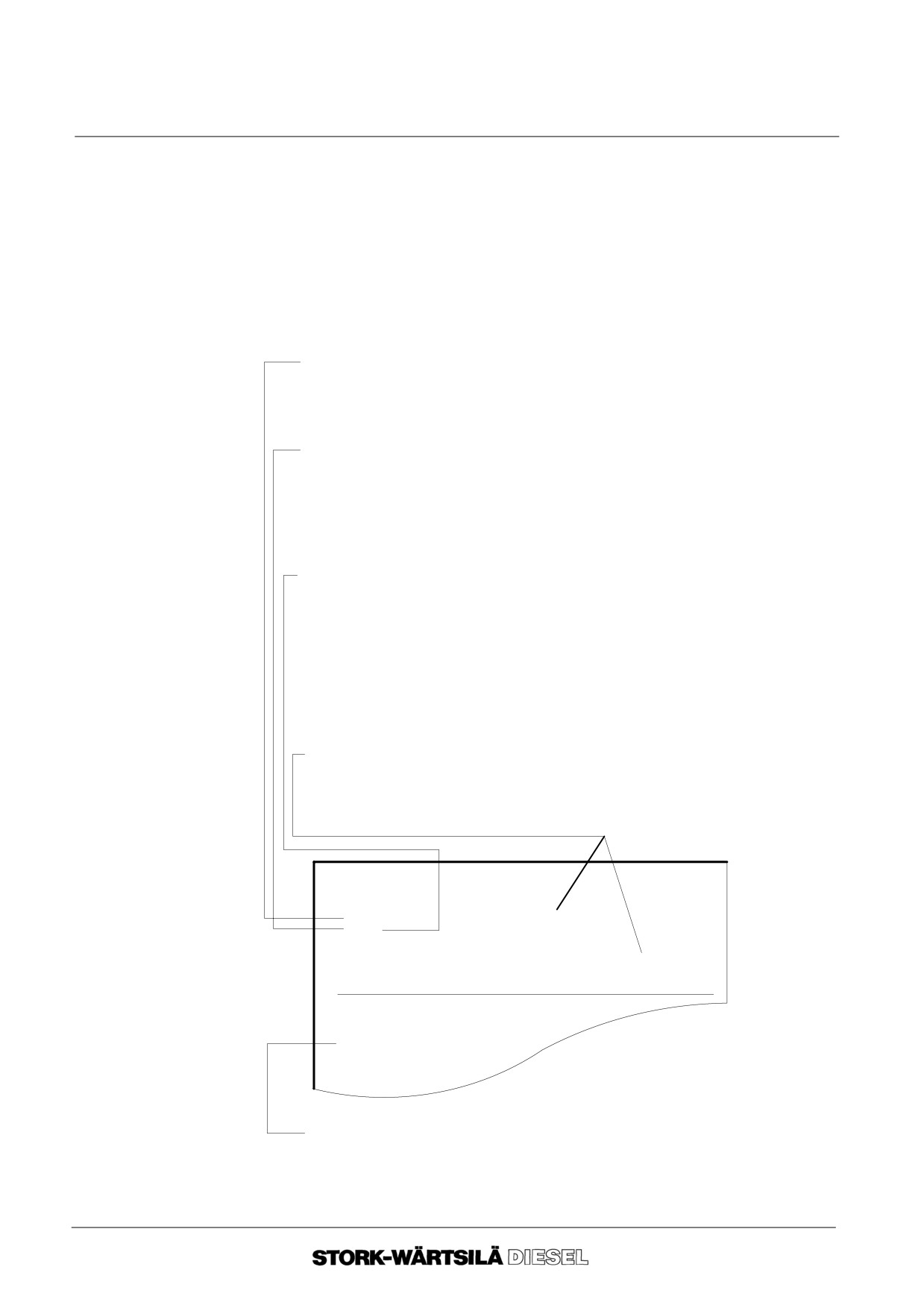
Page setup
Each page consists of a header, (the text above the upper horizontal line), the main
text and the footer, (the part beneath the lower horizontal line).
--
Header:
The header consists of:
TYPE OF MANUAL:
-- MANUAL ;
-- PARTS CATALOGUE.
-- SUB--SUPPLIERS MANUALS.
ENGINE TYPE:
-- engine number in the case of engine specific data.
ENGINE CONFIGURATION:
This is indicated by a letter following the engine type on every page concerned:
-- HFO
= Heavy Fuel Oil ;
-- L
= L--engine ;
-- MDO
= Marine Diesel Oil, (light fuel oil) ;
-- P
= Propulsion ;
-- S
= Stationary / Auxiliary ;
-- V
= V--engine ;
CHAPTER TITLE / SECTION TITLE:
The section title is preceded by the chapter number and a letter for reference
purpose.
Manual
INTRODUCTION
F 240
0C MANUAL SETUP / PAGE SETUP
1. MANUAL SETUP
SUB--SECTION
(This is not a part of the header).
Ver. 01
0 -- 3
Manual
F 240
GENERAL
0C MANUAL SETUP / PAGE SETUP
--
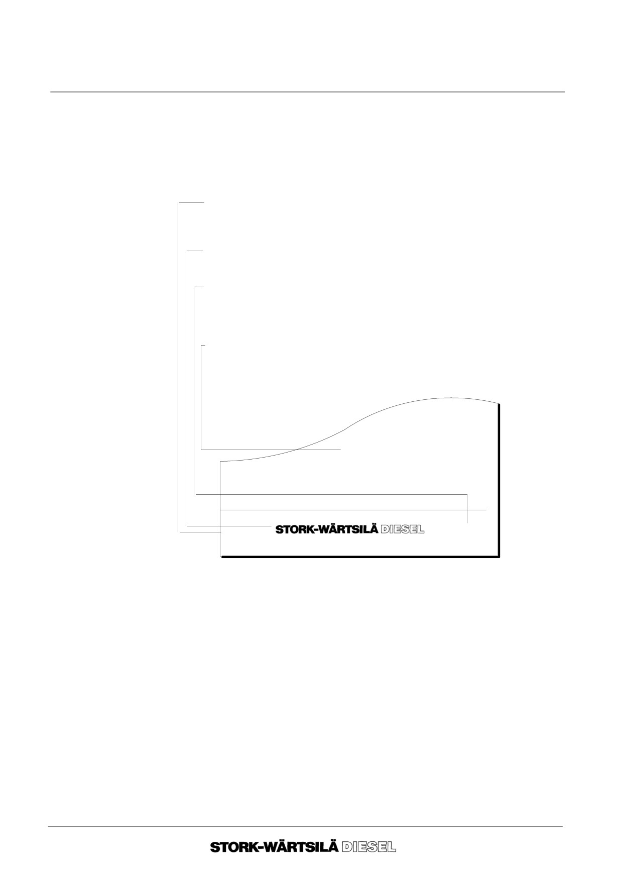
TEXT PART:
The text part of a paragraph is divided into two columns:
-- margin column: for sub dividing of the sections and for indicating the tools ;
-- text column: for the text of the paragraph.
--
FOOTER:
VERSION NUMBER
In case of a relevant modification.
MANUFACTURER’S NAME.
PAGE NUMBERING:
The page number consists of the chapter number followed by the page number.
The page number for each chapter starts with 1.
END--SIGN:
Each section ends with the end--sign.
--o--o--o--o--o--
Ver. 01
0 -- 1
--o--o--o--o--o--
Ver. 01
0 -- 4
Manual
F 240
GENERAL
0D DESCRIPTION OF THE ENGINE
1.
Crankshaft and
The crankshaft is made from a one piece alloy steel forging. The dimensions of the
bedplate
crankpins are identical throughout the range of engines, as are the dimensions of the
main bearing journals in order to optimize standardisation between engine
components of different cylinder configurations. A combined main/axial bearing is lo-
cated at flywheel end. Full rotational balance is achieved by mounting counterbalance
weights. A torsional vibration damper is fitted at the opposite side of the flywheel end.
Full power can be taken either from the flywheel end or from the vibration end of the
engine.
The crankshaft gear wheel is fixed to the crankshaft by means of clamping rings.
The crankshaft is mounted in the bedplate
The main bearings are of tri--metal design with steel back, lead bronze inter layer and
a lead--tin running layer.
2.
Cylinder block
The cylinder block, made of nodular cast iron, is cast in one piece for each cylinder
configuration. It incorporates the cooling water manifold and the camshaft bearings.
When dimensioning, the aim has been to provide low stress levels and good total rigid-
ity. The crankcase covers are fitted to the cylinder block by studbolts and sealed by
a gasket. A number of crankcase covers are equipped with explosion valves for safe
pressure relief in case of high crankcase pressure.
3.
Cylinder liner
The cylinder liners are centrifugally cast of special cast iron. At the bottom the cooling
water space between cylinder block and liner is sealed by three O--rings. The cylinder
liner is above the turning point of the piston provided with special grooves for an
optimal running habit of the piston with the liner.
4.
Piston with
The piston is of the composite type with steel crown and aluminium skirt. The piston
connecting rod
crown is cooled by means of the “cocktail shaker effect” with lubricating oil supplied
through the connecting rod bore, which also lubricates the gudgeon pin bearing. The
piston ring grooves in the steel crown are hardened.
The piston ring set is chrome--plated and consists of three compression rings and one
springloaded, oil scraper ring.
The connecting rod is forged of alloy steel and fully machined. The gudgeon pin
bearings and the connecting rod bearings are of trimetal design with steel back, a lead
bronze inter layer and a lead--tin running layer. The camshaft bearings are of the same
composition.
5.
Cylinder head
The cylinder head is made of alloyed cast iron. The flame plate is relatively thin and
is efficiently cooled by cooling water. The mechanical load is absorbed by a strong
intermediate deck and top deck. The cylinder head is mounted on the cylinder block
with six cylinder head studs. All valve seats are changeable.
6.
Camshaft and
The cams are individually mounted on the camshaft by means of a hydraulic shrink
valve
fit. This allows the cams to be adjusted when necessary. The camfollowers are
mechanism
mounted per cylinder in a guide block.
The camshaft bearings are of the same composition as the connecting rod berarings.
The camshaft is driven by the crankshaft through a gear train.
Ver. 01
0 -- 5
Manual
F 240
GENERAL
0D DESCRIPTION OF THE ENGINE
7. Injection equip-
The injection equipment is made by Bosch. The high pressure fuel pumps are of the
ment
single--cylinder and flow--through type. The fuel injector is centrally located in the cylin-
der head. The fuel supply is through a high pressure fuel line between the high
pressure fuel pump and the injector. The injection equipment is fully separated from
the lubricating oil system.
8. Exhaust manifold
Between exhaust pipe sections expansion compensators are fitted. Exhaust pipes are
insulated by mineral wool and shielded by a sheet metal cover.
9. Turbocharging
The turbochargers are made by Asea Brown Boveri with axial turbines, and roller
and charge air
bearings or plain bearings depending on the type. The turbochargers are arranged at
cooling
the flywheel end of the engine. For cleaning the air side of the turbocharger during
operation there is a water washing device. The air cooler is fitted on to the air inlet
manifold. The water side is accessible by removing the end covers of the cooler.
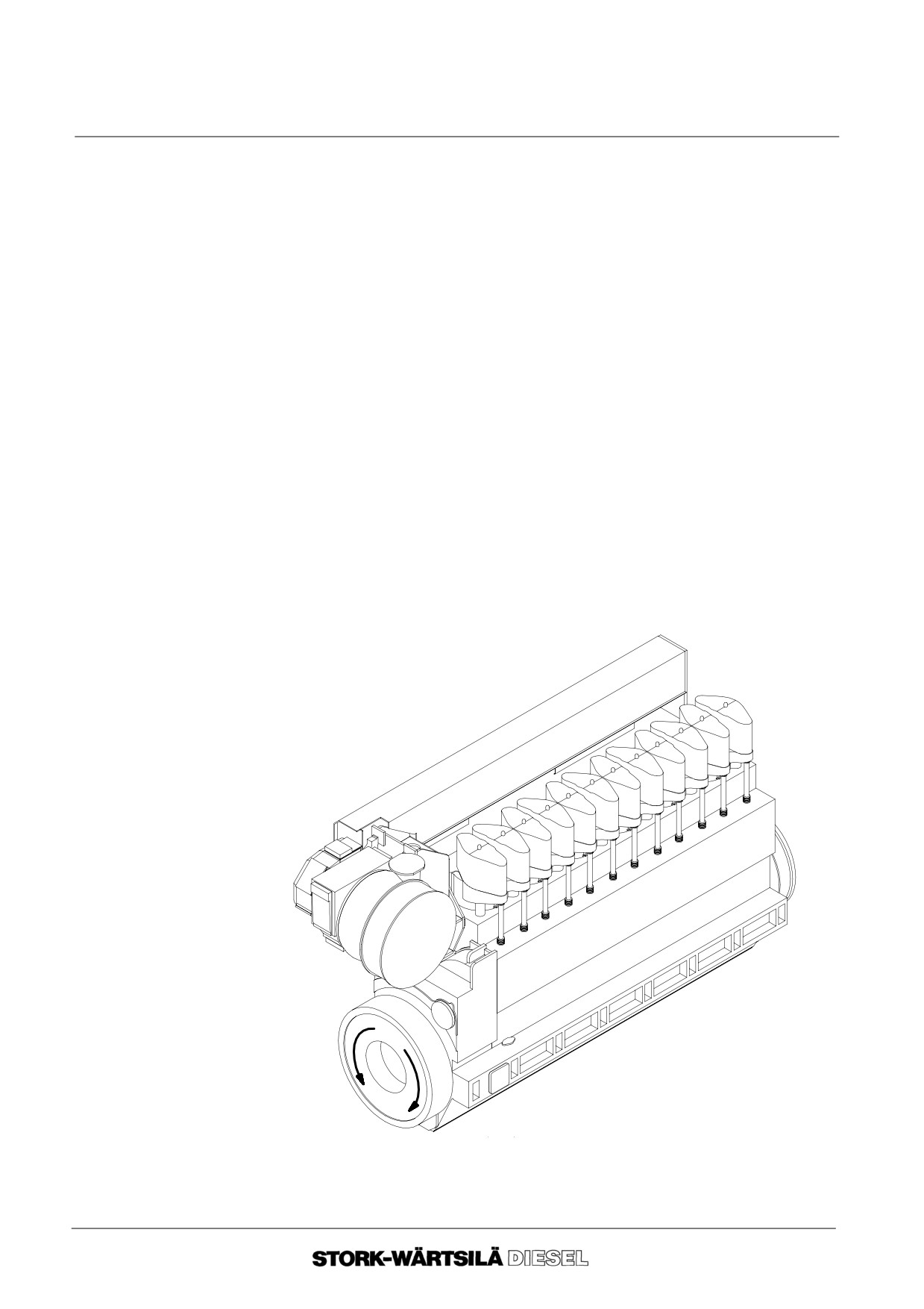
10. Definitions
The cylinders are numbered in ascending order in the direction of the flywheel.
The standard direction of rotation of the engine is ”clockwise” facing the flywheel.
exhaust side
1
2
3
4
5
6
operating side
flywheel end
counter
clockwise
direction of
rotation
clockwise
Ver. 01
0 -- 6
Manual
F 240
GENERAL
0D DESCRIPTION OF THE ENGINE
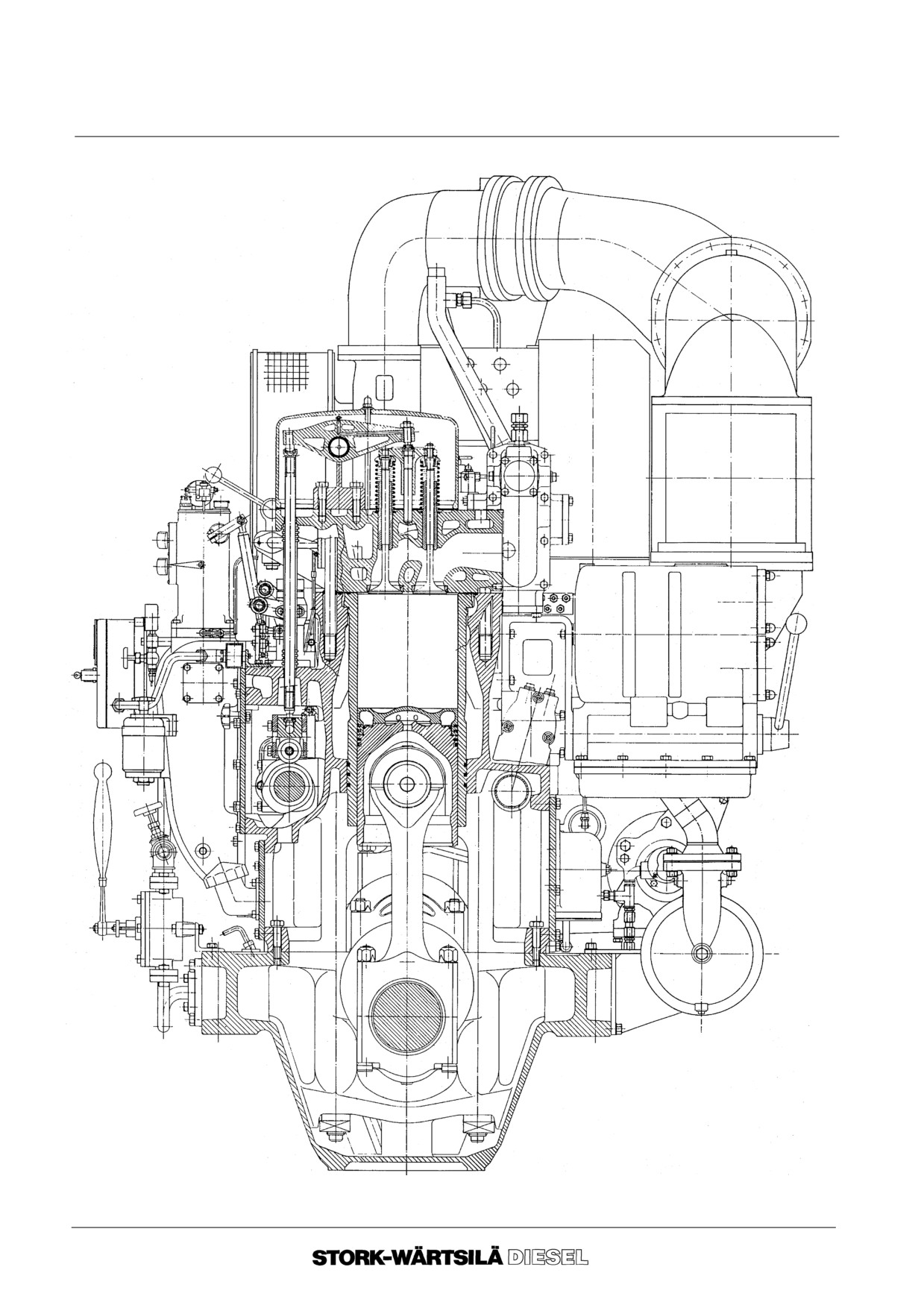
Cross section F240
--o--o--o--o--o--
1000 F 910
Ver. 01
0 -- 7
Manual
F 240
GENERAL
0D DESCRIPTION OF THE ENGINE
Ver. 01
0 -- 8
Manual
F 240
OPERATION
1A GENERAL
1. Commissioning
Commissioning should be carried out under the supervision of a Stork--Wärtsilä Diesel
Service Engineer.
Check before operating the engine for the first time:
-- fuel requirements (section 5B) ;
-- lubricating oil requirements (section 6B) ;
-- cooling water requirements (section 7B) ;
-- inlet air requirements (section 8B) ;
-- alarm and safety system (chapter 10).
2. Operation
General
Engine operation and maintenance affects the reliability, fuel consumption and
satisfactory performance of the engine installation.
Careful attention to operating conditions and maintenance results in lower overall
running costs.
Maintenance
The intervals of inspection and maintenance of the engine, is described in chapter 4
of the manual.
In order to keep the engine in a reliable condition it is important to carry out the
maintenance procedures described in section 4B.
For evaluating engine parts consult the no--go dimensions.
Warning !
Any change in dimensions and/or materials in any of the engine driven components
such as alternator, tail shaft and auxiliary equipment at the driving end can change the
critical speed areas and can therefore be dangerous!
Do not replace or modify engine driven components and/or change the ratio of power
to speed without consultation with Stork--Wärtsilä Diesel service department.
Starting of the
See section 9B of the manual.
engine
In a diesel engine, the crankshaft and its associated dynamic masses form an elastic
During operation
system. The vibration of these masses around the centre line of the shafts in the
system is called torsional vibration. By the use of a vibration damper these vibrations
can usually be kept to an acceptable level. It is not always possible however, to damp
vibrations sufficiently in certain critical speed ranges.
If critical speed areas are present they are shown in red on the tachometer and must
be passed quickly.
Under no circumstances an engine should run continuously in a
restricted speed area.
Ver. 01
1 -- 1
Manual
F 240
OPERATION
1A GENERAL
Stopping the
For stopping the engine see section 9B of the manual. If the engine is to be
engine
non--operational for more than 8 hours then proceed as follows:
2. 1. If the engine is to remain stopped for more than 24 hours close the main fuel
supply valve to the engine in order to prevent leakage.
2. 2. Any defects observed during operation must be repaired immediately.
2. 3. Check and repair leakages immediately.
2. 4. Keep the engine and surrounding areas clean.
--o--o--o--o--o--
Ver. 01
1 -- 2
Manual
F 240
BACKGROUND INFORMATION
2A OPERATION AND SUPERVISION
Normal operation and supervision includes all activities to be done to assure a smooth
and trouble free operation of the complete plant against the lowest costs as well as to
guarantee the safety of the employees working at that plant.
Golden rule
The satisfactorily operation of a diesel engine depends mainly on the
quality of the systems that support the engine.
In order to guarantee a trouble free and smooth plant operation one should take into
account the following remarks.
1.
1.
There is no automatic supervision or control arrangement that replaces an
1.
General
experienced engineer observations.
It is not only a matter of FEEL, LOOK and LISTEN, but also a correct
interpretation of signals from monitoring devices. Do not jumper safety
devices in case of malfunction, but make the safety equipment reliable. In
case the malfunction can not locally be solved contact Stork--Wärtsilä
Diesel.
1.
2.
Have the plant in operation in a way as to which the plant is designed to:
1.
2. 1
The operator has to know what normally can be expected of a plant
in operation and ought to have admission to all relevant technical
data being part of that plant such as:
-- testbed-- and trial protocol
-- manual, parts catalogue and sub--suppliers manuals
-- engine log book for each engine etc.
1.
2. 2
The operator must have full confidence in the process values.
The indicated process values must be true and within small
tolerances.
1.
2. 3
The operator should, by consequent keeping the engine and/or
installation logs, be in time aware of all changes in engine and
installation processes and be able to take necessary corrective
actions. For an advised observation list, see chapter 4A, section 4.
1.
3.
The employees involved should have more than marginal
knowledge of the on--going processes in the engine and installation.
1.
3. 1
The basic acknowledge to be gained by intensive basic studies, by
long term practical experiences on comparable installations and
studies of the relevant manuals available.
1.
4.
The safety of the employees should, during their stay at the plant, be
guarantied in an optimum way.
1.
4. 1
Only under safe working conditions of the employees a safe running
situation of the installation can be realised. Unsafe locations in
general will be avoided.
1.
4. 2
Safety of employees includes also the use of adequate clothes and
shoes complemented with helmed, glasses, gloves and ear
protectors.
1.
4. 3
Furthermore safety of employees depends largely on the observing
of the rules.
2 -- 1
Ver. 01
Manual
F 240
BACKGROUND INFORMATION
2A OPERATION AND SUPERVISION
1.
5.
Sufficient means and ”tools” have to be available for optimum working
capacity of the operator and uninterrupted operation of the engine and
installation.
1.
6.
Run the engine and installation in a safe way.
This can be realised when one keeps the following items in mind:
--
The installation is assembled and in operation according the
manufactures prescriptions.
--
The specified genuine parts have been used.
--
The operator is conversant with systems and their safeties.
--
The reliable working of all safety systems are periodically be approved.
1.
7.
Loading
The way of increasing the output of the engine depends largely on the engine
preheating time and the load level. See also chapter 4C.
1.
8.
Idling should be avoided as much as possible. Warming up of the engine for
more than 5 minutes as well as idling more than 3--5 minutes before stopping
is unnecessary.
Operation at loads below 20% on HFO should be avoided.
When running at low load check that the combustion air after the air cooler do
not contain condensate. Keep the drain always partly open.
1.
9.
Operation at loads below 20 % of rated output should be limited to maximum
100 hours continuously when operating on heavy fuel. Load the engine
above 70 % of rated load for one hour before continuing the low load
operation again.
1.
10.Never try to bring the exhaust gas temperature per cylinder to the same level
by readjusting the rack positions of the HP fuel pumps at operating
conditions.
--o--o--o--o--o--
2 -- 2
Ver. 01
Manual
F 240
BACKGROUND INFORMATION
2B INSPECTION AND MAINTENANCE
Read the following rules carefully before performing any inspection and/or
maintenance work on the engine.
1. General
1. 1. Use the Manual during maintenance work together with the Parts
Catalogue.
1. 2. During all maintenance work, observe the utmost cleanliness and order.
1. 3. Be aware of the risk of crankcase or camshaft case explosion!
Before performing any maintenance or inspection jobs on the engine,
always allow it to cool down sufficiently. A 10 minute cooling period will do
after a normal stop.
1. 4. Observe the fire precautions when maintenance jobs or cleaning of the
engine has to be done.
1. 5. Always shut off the starting air supply to the engine before starting
maintenance work.
1. 6. Always renew lock washers, copper rings, split pins, locking wires, self
locking nuts with nylon and ”O”-- rings when assembling. In case copper
rings have to be used for a second time, please take care for proper
annealing.
1. 7. In general never leave ”O” rings mounted on spare parts. Store ”O”--rings in a
dry, cool and dark place.
2. Removal
2. 1. Before dismantling, check that all pipe systems concerned are drained or
pressure released. After dismantling, cover immediately the holes for
lubricating oil, fuel oil and air with tape, plugs, clean cloth or similar.
2. 2. Provide engine parts of marks for remounting in the same position. Marks on
engine parts should be copied on parts new to be installed at the same
location. Every exchange should be recorded in the engine logbook
mentioning the reason.
2. 3. If heavy parts have to be removed, e.g. a piston with connecting rod, the
crankshaft may start turning due to a sudden unbalance. For safety reasons
always engage the turning gear first and keep it engaged throughout the
jobs.
2. 4. In many instances it is advisable to record clearances before disassembling.
2 -- 3
Ver. 01
Manual
F 240
BACKGROUND INFORMATION
2B INSPECTION AND MAINTENANCE
3. Mounting
3. 1. Make sure that all parts are carefully cleaned (free of carbon deposit) before
mounting. Do not use cotton waste for cleaning the inside of the engine but
always use lint free cleaning rags.
3. 2. For the prescribed glues, lubricants, sealants, see the parts catalogue.
Never use other lubricants when tightening bolt connections of engine
components than those prescribed. If other lubricants are used there is a risk
that the tightening torque, will strongly differ from the one required.
3. 3. Before fitting spare parts which are available as complete sub--assemblies,
all ”O”--rings in these assemblies must be inspected on ageing and damage
and replaced if necessary.
3. 4. In general all piping should be carefully cleaned before installing. New fuel,
lubricating oil and air pipe lines should be acid cleaned and neutralized. This
must also be done after heating jobs have been carried out on the piping
mentioned, to remove any iron oxidation.
Please contact our Service Inspection Department for detailed information.
3. 5. Fit all piping stress free.
4. Last check
4. 1. If upon a check, investigation, control or what so ever the engine shows a
deviation. This deviation first should be corrected. It is to the owners
responsibility to decided to take or keep the engine in operation depending to
the deviation found.
4. 2. It is important after any assembling work to make sure that no tools, parts or
other foreign matters have been left in or on the engine and that all parts
have been thoroughly cleaned before closing the crankcase covers,
camshaft covers and other covers and before starting the engine.
4. 3. Due to the compression ability of some gasket material the pre--stress of
some flange connections should be checked after 24 hours of operation.
--o--o--o--o--o--
2 -- 4
Ver. 01
Manual
F 240
BACKGROUND INFORMATION
2C CRANK DEGREES NINE CYLINDER ENGINE
1.
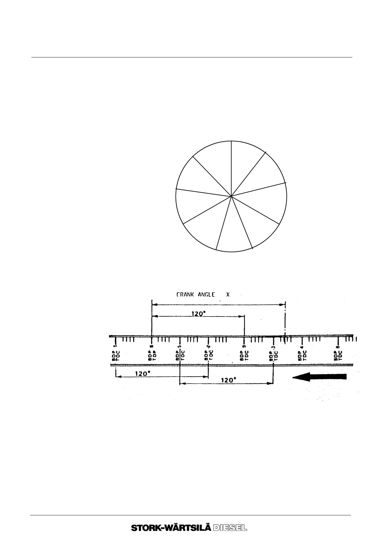
General
Crank Degrees off the Flywheel on 9F240 Engines :
The nine cylinder engines have irregular crank angles, i.e. an irregular number of de-
grees between T.D.C.’s on the flywheel. However, 3 successive crank angles always
add up to 120 crank degrees.
The distance per crank degree can be found by measuring the circumferential dis-
tance across the 120 crank degrees mentioned, with the help of a measuring tape.
1
7
8
38O
44O
38O
38O
6
5
44O
38O
2
4
38O
44O
38O
3
9
9F240 Crank angle diagram
9F240 Crank angles in flywheel
2. Reading
-- Number of crank degrees after Top Dead Centre = X
crankposition
-- Assume the distance across 120 crank degrees is 848 mm (flywheel diameter
810 mm).
-- The distance per crank degree is : 848 / 120 = 7.07mm
It follows that the circumferential distance across crank angle X amounts to X
x 7.07 mm.
--o--o--o--o--o--
Ver. 01
2 -- 5
Manual
F 240
BACKGROUND INFORMATION
2D ENGINE TOOLS
1.
General
Engine tools that are necessary for maintenance jobs on the engine are defined in sec-
tion ”NECESSARY TOOLS” from chapter 11 onwards.
Build--up of this section:
-- description of the function and the code number of the complete tool;
-- item number of the separate tool with description and in brackets the quantity
and code number ;
-- drawing of the tools. The tool concerned is marked with the code number.
2.
Tool
9612F927
The optonal tool 9612 F 927A consists of:
1
Open ended spanner
7x 8
7020 . 206
2
Open ended spanner 10x11
7020 . 212
3
Open ended spanner 13x17
7020 . 219
4
Open ended spanner 19x22
7020 . 223
5
Open ended spanner 24x27
7020 . 229
6
Open ended spanner 30x32
7020 . 235
7
Open ended spanner 36x41
7020 . 240
8
Open ended spanner 46x50
7020 . 245
9
Open ended spanner 32
7020 . 110
10
Flat ring spanner
7022 . 285
11
Box spanner 41 with inside square 1”
7028 . 928
12
Box spanner 60 with inside square 1”
7028 . 946
13
Sliding handle with outside square 1”
7028 . 965
14
Extension piece L=16” with outside square 1”
7024 . 972
15
T--spanner with torsion bar with inside square 8mm.
7024 . 612
16
Outer retaining ring pliers 3 -- 10 mm.
7040 . 511
17
Adjustable spanner 7”
7026 . 007
18
Screw driver 9 mm.
7037 . 068
19
Screw driver 5,5 mm.
7037 . 062
20
Claw foot spanner 22 with torsion bar
7020 . 500
21
Set of feeling gauges
7512 . 012
22
Hook spanner 110/115
9612 F 193
--o--o--o--o--o--
Ver. 01
2 -- 6
Manual
F 240
BACKGROUND INFORMATION
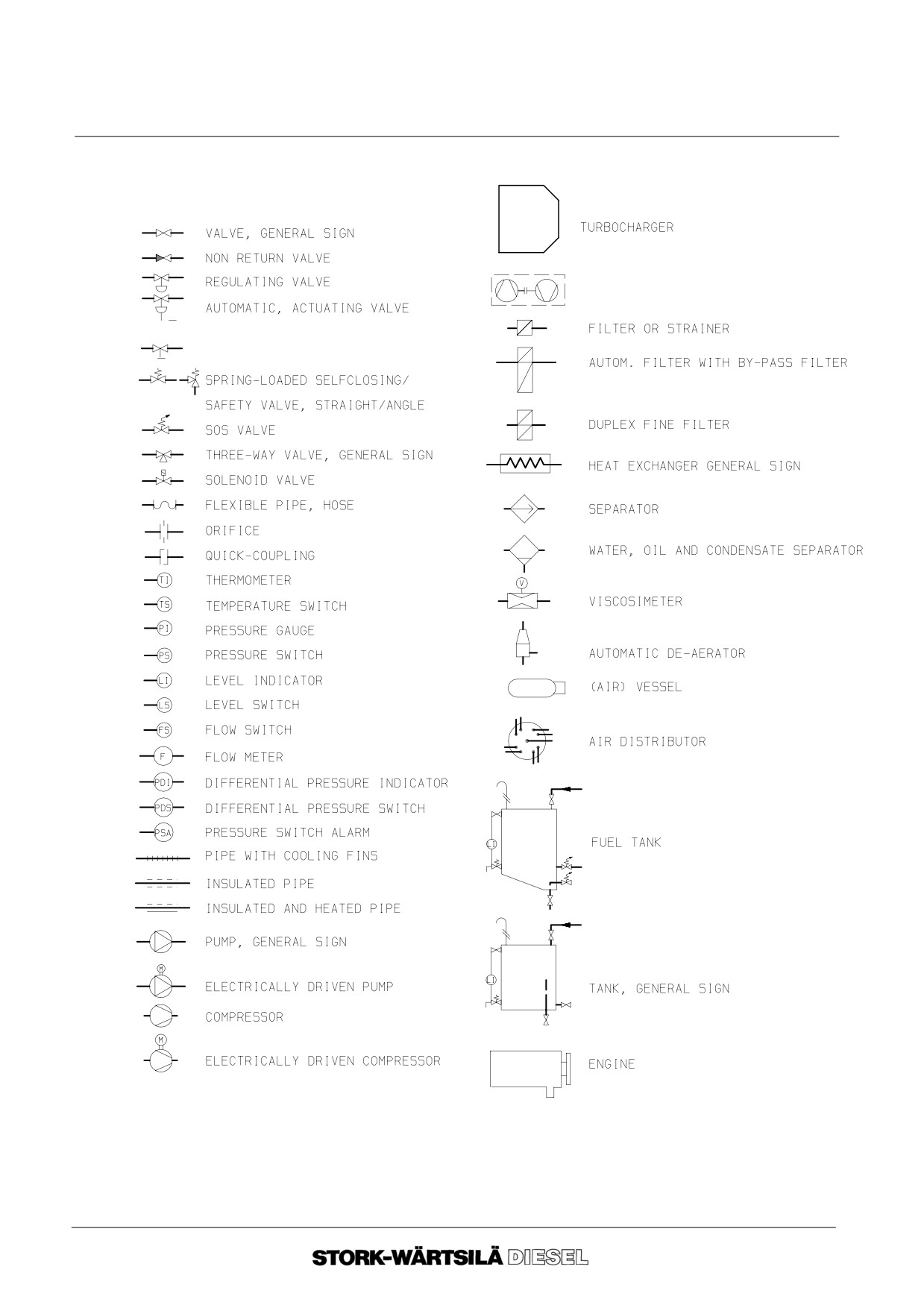
2E INDEX OF SYMBOLS
TURBOCHARGER SCHEMATIC
BUTTERFLY VALVE
9604SW149
--o--o--o--o--o--
Ver. 01
2 -- 7
Manual
F 240
BACKGROUND INFORMATION
2E INDEX OF SYMBOLS
Ver. 01
2 -- 8
Manual
F 240
TECHNICAL DATA
3A MAIN DATA
3. Engine
Type:
Four stroke with direct injection
specifications
Cylinder bore:
240 mm.
Stroke:
260 mm.
Swept volume:
11,8 l / cyl.
Compression ratio:
13 : l.
Configuration:
6, 8 en 9 cylinders in line
Pressure charging:
Turbocharging and air cooler(s).
4. Masses in kg
Engine type
6 F 240
8 F 240
9 F 240
Engine complete (dry)
11.475
14.475
15.730
Cylinder block
2.050
2.880
3.210
Cylinder liner
70
70
70
Cylinder head complete
138
138
138
Oil sump
2.025
2.610
3.210
Crankshaft
1.130
1.400
1.580
Connecting rod
58
58
58
Piston + pin
33
33
33
Flywheel
620
620
620
Lubricating oil filter
110
110
110
Oil cooler
150
170
200
Turbo charger + filter
400
565
565
Air cooler (single)
400
400
400
Air cooler (double)
420
420
420
5. Oil contents
With standard sump
200
230
250
in liters
With enlarged sump
915
1.120
1.240
6. Cooling water
Cooling water capacity without cooler
300
400
450
contents in liters
Ver. 02
3 -- 1
Manual
F 240
TECHNICAL DATA
3A MAIN DATA
7. Cilinder
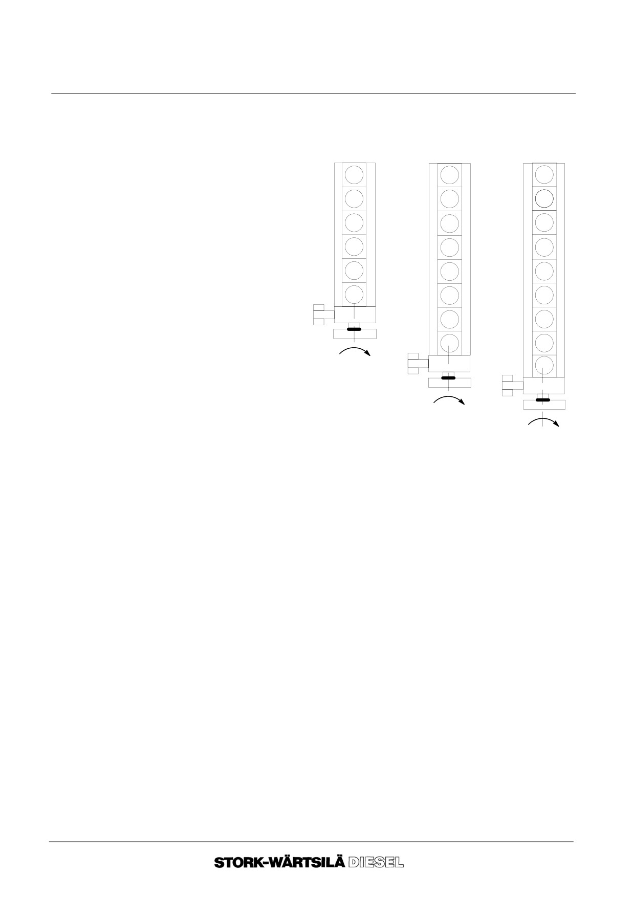
The cylinders are progressively numbered to the flywheel. The cylinder next to the
numbers
flywheel has the highest number.
6 F 240
8 F 240
9 F 240
1
1
1
2
2
2
3
3
3
4
4
4
5
5
5
6
6
6
7
7
8
8
9
Fig. B1
8. Combustion
Normal rotation. (Clockwise as viewed from the flywheel end).
sequence
6 F 240:
1 -- 4 -- 2 -- 6 -- 3 -- 5
8 F 240:
1 -- 6 -- 2 -- 5 -- 8 -- 3 -- 7 --4
9 F 240:
1 -- 5 -- 9 -- 4 -- 7 -- 8 -- 2 -- 3 -- 6
Reverse rotation. (Counter clockwise as viewed from the flywheel end),
6 F 240:
1 -- 5 -- 3 -- 6 -- 2 -- 4
8 F 240:
1 -- 4 -- 7 -- 3 -- 8 -- 5 -- 2 --6
9 F 240:
1 -- 6 -- 3 -- 2 -- 8 -- 7 -- 4-- 9 -- 5
9. Standard
Engines with a speed of 720 --1000 rpm. :
valve timing *)
Opening of the inlet valve:
55o before T.D.C.
Closing of the inlet valve:
51o after B.D.C.
Opening exhaust valve;
51o before B.D.C.
Closing exhaust valve:
55o after T.D.C.
Injection timing :
15o before T.D.C.
*) For actual valve timing, see test report in the parts catalogue.
10. Valve
The nominal valve clearance for engine in cold condition:
clearance
-- between inlet valve stem and rocker arm is: 0,4 mm.
-- between exhaust valve stem and rocker arm is: 0,4 mm.
Ver. 02
3 -- 2
Manual
F 240
TECHNICAL DATA
3A MAIN DATA
11. Pressures
--
Starting air:
30 bar
--
Lubricating oil on main bearings with
normal lub.oil temperature:
3 bar
--
Openings pressure injector :
300 bar
12. Temperatures
--
Lubricating oil before engine
70
C
--
Cooling water after engine :
85
C
--
Max. continuous temperature allowed:
90
C
13. Pump data
Engine type
Engine speed
Output
Boost
omw./min.
m3/h
bar
Cooling water
62), 8 en 9 F
240
720
44
1.7
pump1)
750
46
1.8
900
57.5
2.4
1000
65
3.0
Lubricating oil
6 F 240
720
21
3.2
pump3)
750
22
3.2
900
26
3.2
1000
29
3.2
8 + 9 F 240
720
28
3.5
750
29
3.5
900
35
3.5
1000
39
3.5
2nd Lubricating oil
6 F240
720
28
--
pump with
750
29
--
dry sump3)
900
35
--
1000
39
--
8 + 9 F 240
720
33
--
750
34
--
900
40
--
1000
45
--
4)
Fuel feed pump
6F240
720
6.2 l/min
1.5 bar
750
6.43 l/min
1.5 bar
900
7.75 l/min
1.5 bar
1000
8.6 l/min
1.5 bar
8 + 9 F 240
720
11.7 l/min
1.5 bar
750
12.25 l/min
1.5 bar
900
17.35 l/min
1.5 bar
1000
19.1 3l/min
1.5 bar
1) Cooling water pump speed
= 2,17 x engine speed.
2) Cooling water pump 6 cyl. engine and 1000 rpm. gives 65 m3/hr depending
installation and heat balance.
3) Lubricating oil pump speed
= 1,136 x engine speed.
4) Fuel feed pump speed
= 1,136 x engine speed.
--o--o--o--o--o--
Ver. 02
3 -- 3
Manual
F 240
TECHNICAL DATA
3B TIGHTENING TORQUES
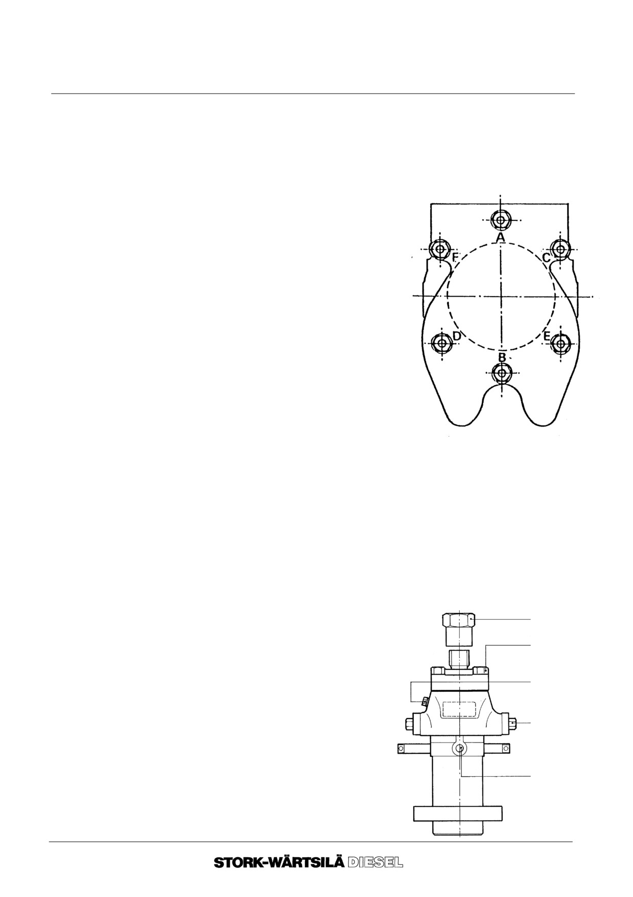
Unless stated otherwise: all threads and contact surfaces of the nuts and bolts should
be sparingly lubricated with engine oil, before tightening.
Never use other lubricants.
Group
Description
Nm
1.
Cylinder
1st step :
Tighten all nuts by hand , tighten nut B with 20 Nm and turn back 30 degr.
head
2nd step :
Tighten all nuts with a torque of 20 Nm
3rd step :
Tighten all nuts with 70 Nm
4th step :
Tighten all nuts with 200 Nm
5th step :
Tighten all nuts with 275 Nm
6th step :
Indicate point zero degrees for the
angular rotation by means of
removeable mark, turn all nuts 60
degrees further.
7th step :
Turn all nuts once more
60 degrees further.
The total angular rotation is 120 degrees.
Note:
Before tightening grease all nuts, studs and
connecting surfaces with engine lubricating oil.
Under no ccondition you should use molycote,
talcum fat or likewise.
--
Bolts for valve rocker bracket
180 Nm
--
Bush around fuel injector
138 Nm
--
Nut of injector clamp
155 Nm
2.
Cylinder
--
Bolts for cylinder block--crankcase, see point
9
block
--
Nuts for tie rods , see point 9
--
Bolts for camshaft bearing caps
65 Nm
--
Studs for cylinder head
690 Nm
3.
Fuel
--
Divers connections on the fuel pump See figure below.
--
Union nut for injector nozzle 160 Nm
45+5 Nm
Attention !
45Nm
Tighten the union nut 3x with160 Nm,
slacken the union nut in between.
20 Nm
40 Nm
10 Nm
Ver. 02
3 -- 4
Manual
F 240
TECHNICAL DATA
3B TIGHTENING TORQUES
Group
Description
Nm
4. Camshaft
--
Bolt in support for intermediate gear wheel
203
--
Bolts for fitting the roll holder
76
5. Connecting rod
--
Nuts for connecting rod cap
1st step
hand tight
2nd step
189
3rd step
383
6. Main bearings
--
Nuts for main bearing caps,
phase I :
42
phase II :
175
phase III :
415
Attention !
Tighten nuts crosswise !
--
Stud (assembly torque)
241
7. Crankshaft
--
Bolts for gear wheel
170
--
Bolts for clamping ring gear wheel
285
--
Bolts for flywheel
1100
--
Bolts for fitting coupling on flywheel
270
--
Bolts for fitting counter weights
480
--
Bolts for vibration damper
a.without output connection :
550
b.with output connection
:
1100
8. Engine / generator
--
Bolts for mounting engine on foundation plate M24
570
on foundation
--
Mounting generator on foundation with:
-- or bolts M24 :
570
-- or bolts M30 :
1150
-- or bolts M36 :
1800
-- or bolts M42 :
2700
Ver. 02
3 -- 5
Manual
F 240
TECHNICAL DATA
3B TIGHTENING TORQUES
9. Assembly
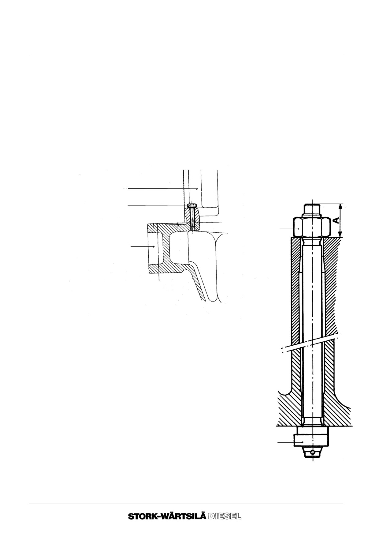
To obtain the right pre--tension on the tie rods, they must be connected the following
tie rods
way:
--
Apply sealing lute between the contact surfaces of cylinder block and crankcase.
--
Place cylinder block on top of the crankcase.
--
Tighten the cylinder block the same day completely on the crankcase, with regard
to hardening of the lute.
--
Fit the small bolts (fig. B2) and tighten them directly with a torque of 275 Nm.
--
Place the tie rods and fit nut “Y” definitively (fig. B3).
Cylinder block
Small bolts
X
Crankcase
Fig. B2
Fig. B3
Y
Ver. 02
3 -- 6
Manual
F 240
TECHNICAL DATA
3B TIGHTENING TORQUES
--
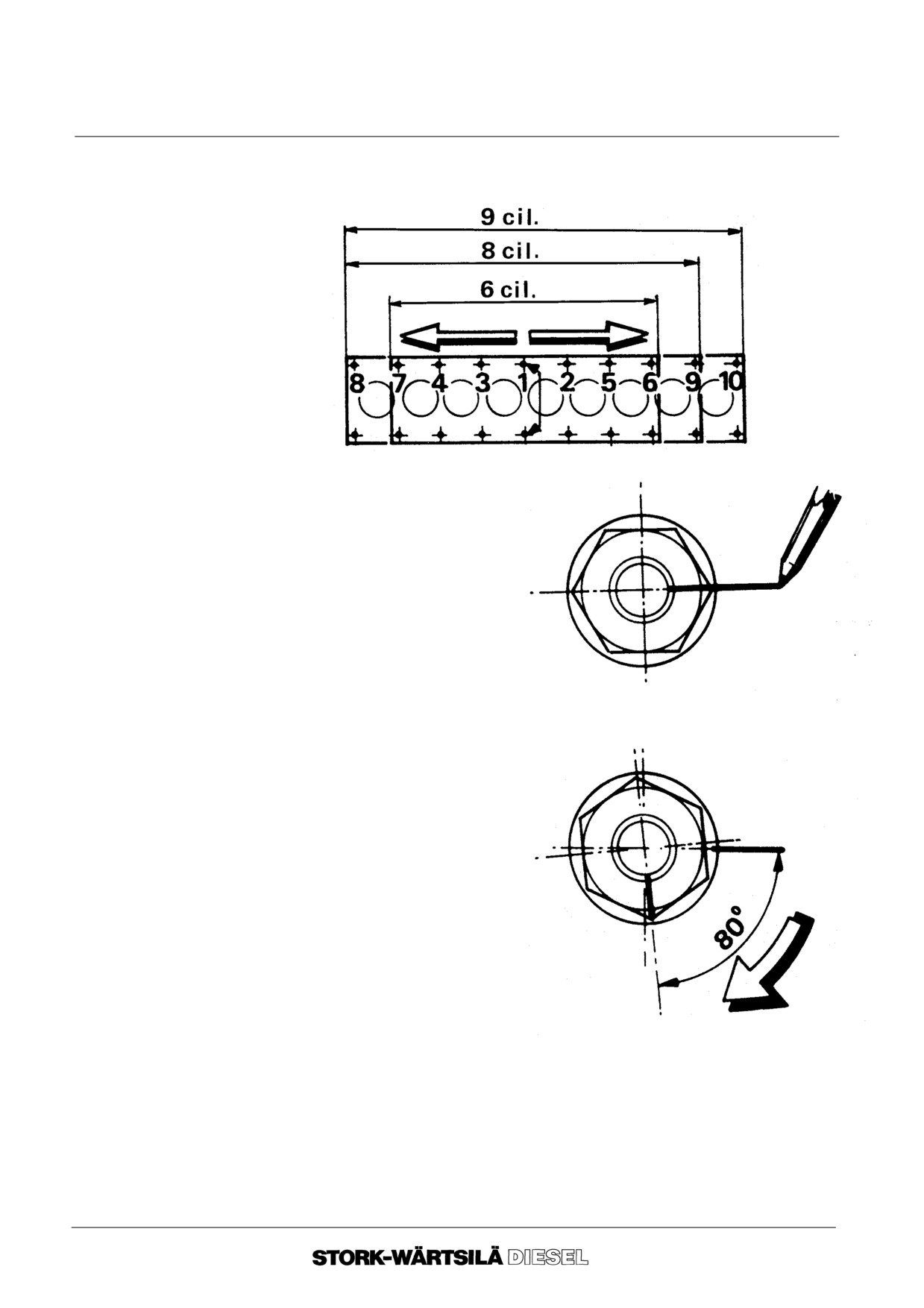
Turn nuts “X” according to sequence diagram (fig. B4), with a torque of 275 Nm.
Repeat this procedure once more . The nuts “Y” should be blocked now.
Fig.
B4
--
Indicate point zero for the
angular rotation by means
of removable pencil on nut
“X” and the cylinder block
(fig. B5).
Fig. B5
--
Turn nut “X” 80
further
(fig. B6).
Fig. B6
--
Tighten the small bolts once more on 275 Nm.
--o--o--o--o--o--
Ver. 02
3 -- 7
Manual
F 240
TECHNICAL DATA
3C NO GO CRITERIA
The given no go criteria and max. allowable clearances are only an indication. The final
decision of replacing a part is the responsibility of the Technical Department and also
depends on the kind of operation.
Stork--Wärtsilä Diesel can therefore take no responsebility for the correctness of this
decision.
Part
Description
No go
Max.
criteria
allowable
clearance
-- -- -- -- -- -- -- -- -- -- -- -- -- -- -- -- -- -- -- -- -- -- -- -- -- -- -- -- -- -- -- -- -- -- -- -- -- -- -- -- -- -- -- -- -- -- -- -- -- -- -- -- -- -- -- -- -- -- -- -- -- -- -- -- -- --
1.
Piston
Maximum diameter on 2 mm from
(2--parts conf.)
top piston
238.60
Cylinder liner
240.60
------------------------------------------------------------------------------------------------------------------------------------
Maximum diameter on 85 mm from
lower part piston
239.75
0.850
Cylinder liner
240.60
------------------------------------------------------------------------------------------------------------------------------------
Groove height 1st and 2nd spring
5.33
0.430
Height
1st and 2nd spring
4.90
------------------------------------------------------------------------------------------------------------------------------------
Groove height 3rd spring
5.24
0.300
Height
3rd spring
4.90
------------------------------------------------------------------------------------------------------------------------------------
Groove height 4th spring
8.14
0.200
Height
4th spring
7.92
------------------------------------------------------------------------------------------------------------------------------------
Bore floating pin in connecting rod
95.15
0.200
Diameter gudgeon pin
94.95
------------------------------------------------------------------------------------------------------------------------------------
Bore floating pin in piston
95.05
0.100
Diameter gudgeon pin
94.95
-- -- -- -- -- -- -- -- -- -- -- -- -- -- -- -- -- -- -- -- -- -- -- -- -- -- -- -- -- -- -- -- -- -- -- -- -- -- -- -- -- -- -- -- -- -- -- -- -- -- -- -- -- -- -- -- -- -- -- -- -- -- -- -- -- --
2.
Connecting
Bore connecting rod bearing
rod
0.300
Diameter gudgeon pin
-- -- -- -- -- -- -- -- -- -- -- -- -- -- -- -- -- -- -- -- -- -- -- -- -- -- -- -- -- -- -- -- -- -- -- -- -- -- -- -- -- -- -- -- -- -- -- -- -- -- -- -- -- -- -- -- -- -- -- -- -- -- -- -- -- --
3.
Main bearing
Bore
(with mounted
*)
0.300
cylinder block)
Diameter crankshaft
-- -- -- -- -- -- -- -- -- -- -- -- -- -- -- -- -- -- -- -- -- -- -- -- -- -- -- -- -- -- -- -- -- -- -- -- -- -- -- -- -- -- -- -- -- -- -- -- -- -- -- -- -- -- -- -- -- -- -- -- -- -- -- -- -- --
4.
Axial bearing
Axial length
0.500
Axial length between the crankwebs
-- -- -- -- -- -- -- -- -- -- -- -- -- -- -- -- -- -- -- -- -- -- -- -- -- -- -- -- -- -- -- -- -- -- -- -- -- -- -- -- -- -- -- -- -- -- -- -- -- -- -- -- -- -- -- -- -- -- -- -- -- -- -- -- -- --
Ver. 02
3 -- 8
Manual
F 240
TECHNICAL DATA
3C NO GO CRITERIA
Part
Description
No go
Max.
criteria
allowable
clearance
-- -- -- -- -- -- -- -- -- -- -- -- -- -- -- -- -- -- -- -- -- -- -- -- -- -- -- -- -- -- -- -- -- -- -- -- -- -- -- -- -- -- -- -- -- -- -- -- -- -- -- -- -- -- -- -- -- -- -- -- -- -- -- -- -- --
5.
Camshaft
Bore camshaft bearing
0.250
Diameter camshaft
-- -- -- -- -- -- -- -- -- -- -- -- -- -- -- -- -- -- -- -- -- -- -- -- -- -- -- -- -- -- -- -- -- -- -- -- -- -- -- -- -- -- -- -- -- -- -- -- -- -- -- -- -- -- -- -- -- -- -- -- -- -- -- -- -- --
6.
Camshaft
Bore in bush intermediate gear
drive
crankshaft/camshaft
0.200
Diameter shaft of the gear wheel
------------------------------------------------------------------------------------------------------------------------------------
Roll holder
0.200
Bore in holder
------------------------------------------------------------------------------------------------------------------------------------
Diameter tap for bush
0.200
Bore roll holder
------------------------------------------------------------------------------------------------------------------------------------
Bore of the rolls
0.300
Diameter of the bush
------------------------------------------------------------------------------------------------------------------------------------
Bore of the bush
0.200
Diameter tap for bush
-- -- -- -- -- -- -- -- -- -- -- -- -- -- -- -- -- -- -- -- -- -- -- -- -- -- -- -- -- -- -- -- -- -- -- -- -- -- -- -- -- -- -- -- -- -- -- -- -- -- -- -- -- -- -- -- -- -- -- -- -- -- -- -- -- --
7.
Valves
Diameter valve guide, measuring
(inlet and
about 20 mm from the ends
exhaust)
0.200
Diameter valve stem
-- -- -- -- -- -- -- -- -- -- -- -- -- -- -- -- -- -- -- -- -- -- -- -- -- -- -- -- -- -- -- -- -- -- -- -- -- -- -- -- -- -- -- -- -- -- -- -- -- -- -- -- -- -- -- -- -- -- -- -- -- -- -- -- -- --
8.
Lubricating
Bore bearing bushes
oil pump
0.200
Diameter rotor shaft
-- -- -- -- -- -- -- -- -- -- -- -- -- -- -- -- -- -- -- -- -- -- -- -- -- -- -- -- -- -- -- -- -- -- -- -- -- -- -- -- -- -- -- -- -- -- -- -- -- -- -- -- -- -- -- -- -- -- -- -- -- -- -- -- -- --
*) If the white metal layer of the bearing scales is worn for more than 25%, exposing
the bronze layer underneath, the bearing scales should be replaced.
--o--o--o--o--o--
Ver. 02
3 -- 9
Manual
F 240
TECHNICAL DATA
3C NO GO CRITERIA
Ver. 02
3 -- 10
Manual
F 240
INSPECTION AND MAINTENANCE
4A GENERAL
9.
General
This chapter describes the inspection and maintenance procedures.
Section 4B gives a description when and which inspection and maintenance actions
have to be carried out. In case you need any further explanation, contact the service
department of Stork--Wärtsilä Diesel.
With the aid of the test report and earlier observations list it is possible to detect and
resolve faults by calculated actions.
10. Daily check
10. 1.Observation lists:
For the purpose of keeping a close check on the engine in operation it is advised
to keep a log book of temperatures and pressures, speeds and engine adjust-
ments. This provides a good overview of the normal values, so that deviations
can be detected early.
10. 2.Fluid levels:
These checks should include the following items:
-- oil level, engine ;
-- oil level, turbocharger(s)
(not applicable to VTC turbochargers) ;
-- level of fresh cooling water system(s) ;
-- oil level governor ;
-- level of daily service fuel tank.
10. 3.Leaks:
During operation, check engine externally for leakage:
-- fuel system ;
-- lubricating oil system ;
-- cooling water system ;
-- air intake system and exhaust gas system ;
-- start and stop system ;
10. 4.Draining:
The daily service tank must be regularly drained at its lowest point, in order to
ensure that no contamination or water residues can get into the engine’s fuel sys-
tem.
The air bottles and filter of the water separator should be regularly drained at their
lowest points to prevent impurities and condensate from getting into the engine’s
starting air and stop system.
10. 5.Thermometers, pressure gauges:
Check daily thermometers and pressure gauges for proper performance
Defective thermometers can be renewed when engine is stopped. During opera-
tion only the upper part can be replaced. Then remove the rest from the lower
part.
Badly vibrating pressure gauge pointers may lead to gauge failure and make it
difficult to take readings. To stop pointers from vibrating it is recommended to
shut the pressure gauge cocks to the point of minimal vibration.
Another method that will help to spare the pressure gauges is to keep the gauge
cocks fully shut, and to open them a little each time a pressure reading is wanted.
Ver. 01
4 -- 1
Manual
F 240
INSPECTION AND MAINTENANCE
4A GENERAL
11. Weekly check
Check the quality of the engine cooling water weekly and when the water is changed,
and/or each time cooling water agents are added.
The manufacturers’ specifications and instructions for the relevant products should be
followed with regard to the use of additives and tests of the quality of the engine cooling
water.
Ver. 01
4 -- 2
Manual
F 240
INSPECTION AND MAINTENANCE
4A GENERAL
12. OBSERVATION
DATE ..--..--..
day
LIST
Time
Engine speed
rpm.
Turbocharger speed
rpm.
Fuel control rod position
mm.
Load
KW
HT cooler
bar
LT--cooler
bar
Lubricating oil
bar
Fuel
bar
Receiver pressure
bar
Exhaust gases after turboch.
m.bar
Barometer
m.bar
Inlet air
oC
Air after turbocharger
oC
Air after cooler
oC
Water before air coolers
oC
Water before oil coolers
oC
Lubricating oil before coolers
oC
Lubricating oil after coolers
oC
Lubricating oil before engine
oC
HT--water before the engine
oC
HT--water after the engine
oC
Exhaust gases cyl.1
oC
”
cyl.2
oC
”
cyl.3
oC
”
cyl.4
oC
”
cyl.5
oC
”
cyl.6
oC
”
cyl.7
oC
”
cyl.8
oC
”
cyl.9
oC
Exhaust gases after turboch.
oC
Barrier oil pressure
bar
Fuel consumption
kg/h
Specific fuel consumption
g/KWh
--o--o--o--o--o--
Ver. 01
4 -- 3
Manual
F 240
INSPECTION AND MAINTENANCE
4B INSPECTION AND MAINTENANCE PROCEDURES
Inspection and maintenance procedures are described in this section.
1.
Maintenance
The total running hours between the overhauls as well as the effective life of components
interval / effective
are guide lines and depend on the following aspects:
life
--
the operation and the maintenance of the engine in accordance with instructions
as specified in the engine documentation ;
--
make sure that everyone concerned with the maintenance of the engine is trained
and qualified, has this engine documentation available, reads it and understands
it ;
--
to guarantee the best efficiency, reliability and lifetime of the engine and its
components, only original spare parts should be used ;
--
the load of the engine is between 60% en 100% of the output indicated on the
engine type plate with 3,000 to 6,000 running hours per year ;
--
the fuel quality ;
--
the lubricating oil quality ;
--
the humidity of the air ;
--
environmental conditions like temperatures and vibrations;
Strong deviation from one of the above described factors should result in adaptation of
the running hours between the overhauls and/or the effective life time of the components.
Some remarks about the procedures described in this chapther:
--
The operations to be carried out are subdivided into groups. In a number of cases
you will find cross references, namely:
--
4A
section 4A of the manual ;
--
10--
chapter 10 of the manual ;
-- PC
PARTS CATALOGUE.
-- SSM
SUB--SUPPLIER’S MANUALS ;
--
Weekly maintenance includes daily maintenance. The 750--hours maintenance
includes the weekly and daily maintenance operations. And so on.
--
Carry out the following overhauls:
--
750 hours overhaul at 750, 2,250, 3,750-- and 5,250 running hours ;
--
1,500 hours overhaul at 1,500-- and 4,500 running hours ;
--
3,000 hours overhaul at 3,000 running hours ;
--
6,000 hours overhaul at 6,000 running hours.
--
This starting point applies also to intervals above 6.000 running hours.
2.
Inspection
Inspections should be started at cylinder 1 and subsequently cylinder 2 etc. If it has been
found that for instance two valve rotators are in bad condition, repeat the same procedure
for two other cylinders. If the result of this second inspection is also negative, renew all
valve rotators.
Ver. 01
4 -- 4
Manual
F 240
INSPECTION AND MAINTENANCE
4B INSPECTION AND MAINTENANCE PROCEDURES
3. Daily maintenance
3. 1. Inlet/outlet
8C o Check if both water condensate drains in the air inlet casing are open ;
system
8D o Clean the turbocharger on the compressor side by means of water injection.
3. 2. Alarm system
10--o Check, if the alarm system is engaged and check the working of the alarm
system ;
10--o Check the overspeed device by using the test key.
3. 3. Routine
o Check the outside of the engine for leakages ;
handlings
4A o Keep the observation lists up to date and check for deviations ;
o Check the fluid levels ;
o Check the working of pressure gauges and thermometers visually ;
6C o Check the pressure difference of the lubricating oil filter, renew the filter elements
if the difference is too high ;
o Drain any impurities and water condensate from the day tank ;
o Drain water condensate from the air bottles ;
o Drain water condensate from the filter--water separator of the stopping device.
Ver. 01
4 -- 5
Manual
F 240
INSPECTION AND MAINTENANCE
4B INSPECTION AND MAINTENANCE PROCEDURES
4. Weekly
maintenance
4.
1.
Fuel system
o Check the governor and fuel rack linkage and keep it running easily.
4.
2.
Lubricating oil
6D o Clean the centrifugal by--pass lubricating oil filter and renew the insert filter paper
system
;
6E o Check the working of the inlet valve seat lubrication visually.
4.
3.
Cooling water
7B o Check the fluid level and the concentrations of the cooling water inhibitors.
system
4.
4.
Inlet/outlet
SSMo Clean the air inlet filter ;
system
8C o Check if both water condensate drains in the air inlet casing are open ;
8D o Clean the turbocharger on the compressor side by means of water injection.
4.
5.
Alarm system
10--o Check if the alarm system is engaged and check the working of the alarm system;
10--o Check the overspeed device by using the test key.
4.
6.
Routine
o Check the outside of the engine for leakages ;
handlings
4A o Keep the observation lists up to date and check for deviations ;
o Check the fluid levels ;
o Check the working of pressure gauges and thermometers visually ;
6C o Check the pressure difference of the lubricating oil filter, renew the filter elements
if the difference is too high ;
o Drain any impurities and water condensate from the day tank ;
o Drain water condensate from the air bottles ;
o Drain water condensate from the filter--water separator of the stopping device.
Ver. 01
4 -- 6
Manual
F 240
INSPECTION AND MAINTENANCE
4B INSPECTION AND MAINTENANCE PROCEDURES
5.
750--Hours
overhaul
5. 1. Fuel system
o Check the governor and fuel rack linkage and keep it running easily.
5. 2. Lubricating oil
6B o Check the quality of the lubricating oil ;
system
6D o Clean the centrifugal by--pass lubricating oil filter and renew the insert filter
paper ;
Ssm o Change the lubricating oil of the turbocharger of VTR--type ;
20C o Change the lubricating oil in the governor ;
6E o Check the working of the inlet valve seat lubrication visually.
5. 3. Cooling water
7B o Check the fluid level and the concentrations of the cooling water inhibitors.
system
5. 4. Inlet/outlet
Ssm o Clean the air inlet filter ;
system
8C o Check if both water condensate drains in the air inlet casing are open ;
8D o Clean the turbocharger on the compressor side by means of water injection.
5. 5. Alarm system
10--o Check if the alarm system is engaged and check the working of the alarm system;
10--o Check the overspeed device by using the test key.
5. 6. Routine
o Check the outside of the engine for leakages ;
handlings
4A o Keep the observation lists up to date and check for deviations ;
o Check the fluid levels ;
o Check the working of pressure gauges and thermometers visually ;
6C o Check the pressure difference of the lubricating oil filter, renew the filter elements
if the difference is too high ;
o Drain any impurities and water condensate from the day tank ;
o Drain water condensate from the air bottles ;
o Drain water condensate from the filter--water separator of the stopping device.
Ver. 01
4 -- 7
Manual
F 240
INSPECTION AND MAINTENANCE
4B INSPECTION AND MAINTENANCE PROCEDURES
6.
1,500--Hours
overhaul
6. 1. Cylinder head /
18G o Check the valve clearance and adjust it if necessary.
valves
6. 2. Fuel system
o Check the governor and fuel rack linkage and keep it running easily ;
5C o Replace the fuel filter elements.
6. 3. Lubricating oil
6B o Check the quality of the lubricating oil ;
system
SSMo Change the lubricating oil of the turbocharger of VTR--type ;
20C o Change the lubricating oil in the governor ;
6D o Clean the centrifugal by--pass lubricating oil filter and renew the insert filter paper
;
6E o Check the working of the inlet valve seat lubrication visually.
6. 4. Cooling water
7B o Check the fluid level and the concentrations of the cooling water inhibitors.
system
6. 5. Inlet/outlet
SSMo Clean the air inlet filter ;
system
8C o Check if both water condensate drains in the air inlet casing are open ;
8D o Clean the turbocharger on the compressor side by means of water injection.
6. 6. Alarm system
10--o Check if the alarm system is engaged and check the working of the alarm system;
10--o Check the overspeed device by using the test key.
6. 7. Routine
o Check the outside of the engine for leakages ;
handlings
4A o Keep the observation lists up to date and check for deviations ;
o Check the fluid levels ;
o Check the working of pressure gauges and thermometers visually ;
6C o Check the pressure difference of the lubricating oil filter, renew the filter elements
if the difference is too high ;
o Drain any impurities and water condensate from the day tank ;
o Drain water condensate from the air bottles ;
o Drain water condensate from the filter--water separator of the stopping device.
Ver. 01
4 -- 8
Manual
F 240
INSPECTION AND MAINTENANCE
4B INSPECTION AND MAINTENANCE PROCEDURES
7.
3,000--Hours
overhaul
7. 1. Cylinder head /
18G o Check the valve clearance and adjust it if necessary.
valves
7. 2. Fuel system
o Check the governor and fuel rack linkage and keep it running easily ;
5C o Renew the fuel filter elements ;
17--o Check all the nozzles on good working, renew if necessary ;
5E o Test the constant pressure valves ;
o Inspect the inside of one high pressure fuel pipe on cavitation ;
3A o Check the injection moment of one fuel pump.
7. 3. Lubricating oil
6B o Check the quality of the lubricating oil ;
system
SSMo Change the lubricating oil of the turbocharger of VTR--type ;
20C o Clean the inside of the governor and change the lubricating oil in the governor;
6D o Clean the centrifugal by--pass lubricating oil filter and renew the insert filter
paper ;
6E o Check the working of the inlet valve seat lubrication visually.
6F o Check barrier oil H.P.fuel pump, if applicable.
7. 4. Cooling water
7D o Inspect from the cooling water side:
system
o Water cooler ;
o Lubricating oil cooler ;
o Air cooler ;
Replace, if necessary, the anodes ;
7B o Check the fluid level and the concentrations of the cooling water inhibitors.
7. 5. Inlet/outlet
SSMo Clean the air inlet filter ;
system
8C o Check if both water condensate drains in the air inlet casing are open ;
8D o Clean the turbocharger(s) on the compressor side by means of water injection.
7. 6. Alarm system
10--o Check if the alarm system is engaged and check the working of the alarm system;
10--o Check the overspeed device by using the test key.
7. 7. Routine
o Check the outside of the engine for leakages ;
handlings
4A o Keep the observation lists up to date and check for deviations ;
o Check the fluid levels ;
o Check the working of pressure gauges and thermometers visually ;
6C o Check the pressure difference of the lubricating oil filter, renew the filter elements
if the difference is too high ;
o Drain any impurities and water condensate from the day tank ;
o Drain water condensate from the air bottles ;
o Drain water condensate from the filter--water separator of the stopping device.
Ver. 01
4 -- 9
Manual
F 240
INSPECTION AND MAINTENANCE
4B INSPECTION AND MAINTENANCE PROCEDURES
8.
6,000--Hours
overhaul
8. 1. Cylinder head /
15B o Inspect the running surface of the cylinder liners by means of an endoscope;
valves /
18 o Inspect all the valves and the valve seats by means of an endoscope ;
cylinder liner
18G o Check the valve clearance and adjust it if necessary.
8. 2. Miscellaneous
14A o Check the working of the explosion valves ;
/ inspections
9C o Check the drive and performance of the starting air distributor ;
13B o Inspect the crankshaft space ;
20A o Inspect the governor drive.
8. 3. Engine
23A o Check the foundation bolts and filling pieces underneath the engine and, if appli-
arrangement
cable, the flexible elements underneath the foundation plate ;
o If applicable check the condition of the epoxy resin filling by means of checking the
measuring points ;
o Check the condition of the flexible elements of the flexible coupling ;
23A o Check the engine alignment ;
23B o Measure the crankshaft deflections and measure the axial play of the crankshaft.
8. 4. Fuel system
o Check the governor and fuel rack linkage and keep it running easily ;
5C o Renew the fuel filter elements ;
o Check the O--rings of a fuel connecting piece of one fuel pump ;
17--o Replace the wearing plates and nozzles of the nozzle holder, check the fuel
injectors on good working ;
5E o Test the constant pressure valves ;
o Inspect the inside of one high pressure fuel pipe on cavitation ;
5D o Check the injection moment of one fuel pump.
8. 5. Camshaft
19--o Check the cams, rollers, roller holders and pivots visually.
8. 6. Lubricating oil
6B o Check the quality of the lubricating oil ;
system
6D o Clean the centrifugal by--pass oil filter and renew the insert filter paper ;
20C o Clean the inside of the governor and change the lubricating oil ;
6E o Check the working of the inlet valve seat lubrication visually ;
6F o Check barrier oil H.P.fuel oil pump, if applicable;
6G o Check that the safety valve and overflow valve are in good working order.
8. 7. Cooling water
7D o Inspect from the cooling water side:
system
o Water cooler ;
o Lubricating oil cooler ;
o Air cooler ;
Replace, if necessary, the anodes ;
7B o Check the fluid level and the concentrations of the cooling water inhibitors.
Ver. 01
4 -- 10
Manual
F 240
INSPECTION AND MAINTENANCE
4B INSPECTION AND MAINTENANCE PROCEDURES
Continued
6,000--hours
8. 8. Inlet/outlet
oHave the turbochargers completely cleaned, inspected and overhauled if
system
necessary ;
o Inspect the air cooler at the air inlet side by means of an endoscope ;
SSMo Clean the air inlet filter ;
8C o Check if both water condensate drains in the air inlet casing are open ;
o Inspect the air cooler at air inlet side by means of an endoscope and clean the air
cooler, if necessary.
8. 9. Alarm system
10--o Check if the alarm system is engaged and check the working of the alarm system;
10--o Check the overspeed device by using the test key ;
o Check the lubricating oil level switch, If applicable;
o Calibrate the temperature switches and pressure switches.
8. 10. Routine
o Check the outside of the engine for leakages ;
handlings
4A o Keep the observation lists up to date and check for deviations ;
o Check the fluid levels ;
o Check the working of pressure gauges and thermometers visually ;
6C o Check the pressure difference of the lubricating oil filter, renew the filter elements
if the difference is too high ;
o Drain any impurities and water condensate from the day tank ;
o Drain water condensate from the air bottles ;
o Drain water condensate from the filter--water separator of the stopping device.
8. 11. Running
4C o Start the engine for test running ;
engine
10--o Check visually if alarm system is switched on at 250 rpm ;
10--o Check visually if the alarm system is switched on at 500 rpm for second stage
lubricating oil pressure (Engines with variable speed) ;
10--o Test the overspeed function by means of the test key (nominal speed 60%).
Ver. 01
4 -- 11
Manual
F 240
INSPECTION AND MAINTENANCE
4B INSPECTION AND MAINTENANCE PROCEDURES
9.
12,000--Hours
overhaul
9. 1. Cylinder head /
15B o Inspect the running surface of the cylinder liners by means of an endoscope;
valves /
18--o Inspect all valves and valve seats by means of an endoscope ;
cylinder liner
18--o Remove one cylinder head for visual inspection of the cylinder head, the valves and
the valve seats ;
18J o Remove one starting air valve for visual inspection.
9. 2. Piston and
16--o Remove one piston with connecting rod for visual inspection ;
connecting rod
16--o Remove one set of big end bearings for visual inspection ;
16--o Remove one gudgeon pin for visual inspection of the gudgeon pin bush ;
16--o Inspect 1 set of piston rings and measure the piston ring grooves.
9. 3. Miscellaneous
14A o Inspect all the explosion valves on good working order ;
/ inspections
9C o Check the drive and performance of the starting air distributor ;
13A o Inspect the crankshaft space ;
20A o Inspect the governor drive ;
11-- o Remove one main bearing for visual inspection ;
o Check the wear and the condition of the gears in the gearbox by means of an endo-
scope ;
o Check the wear and the condition of the gears in the engine ;
18G o Check the valve clearance and adjust it if necessary.
9. 4. Engine
23A o Check the foundation bolts and filling pieces underneath the engine and, if appli-
arrangement
cable, the flexible elements underneath the foundation plate ;
o If applicable check the condition of the epoxy resin filling by means of checking the
measuring points;
o Check the condition of the flexible elements of the flexible coupling ;
23A o Check the engine alignment ;
23B o Measure the crankshaft deflections and measure the axial play of the crankshaft.
9. 5. Fuel system
17--o Have all the fuel injectors overhauled ;
5D o Have one high pressure fuel pump checked and calibrated ;
o Inspect the inside of one high pressure fuel pipe on cavitation ;
o Check the fuel connecting piece of one fuel pump and replace the O--rings ;
5E o Test the constant pressure valves ;
o Check the governor and fuel rack linkage and keep it running easily ;
5C o Renew the fuel filter elements ;
5D o Check the injection moment of one fuel pump.
9. 6. Camshaft
19--o Check the cams, rollers, roller holders and pivots visually.
Ver. 01
4 -- 12
Manual
F 240
INSPECTION AND MAINTENANCE
4B INSPECTION AND MAINTENANCE PROCEDURES
Continued
12,000--hours
9.
7.
Lubricating oil
6
o Replace the lubricating oil depending of the system contents, or check the quality
system
of the lubricating oil ;
20C o Clean the inside of the governor and change the lubricating oil ;
22A o Take a sample of the vibration damper fluid and have it examined ;
6D o Clean the centrifugal by--pass oil filter and renew the insert filter paper ;
6E o Check the working of the inlet valve seat lubrication visually ;
6F o Check barrier oil H.P.fuel pump, if applicable ;
6G o Check that the safety valve and overflow valve are in good working order.
9.
8.
Cooling water
o Overhaul the cooling water pump of the HT--circuit ;
system
o Overhaul the cooling water pump of the LT--circuit ;
7D o Inspect from the cooling water side:
o Water cooler ;
o Lubricating oil cooler ;
Replace, if necessary, the anodes ;
7C o Check the de--aeration.
9.
9.
Inlet/outlet
o Have the turbochargers completely overhauled ;
system
7D o Overhaul the air cooler ;
SSMoRenew the air inlet filter material ;
8C o Check if both water condensate drains in the air inlet casing are open.
9.
10. Alarm system
10--o Check if the alarm system is engaged and check the working of the alarm system;
10--o Check the overspeed device by using the test key ;
o Check the starting conditions and If applicable the starting security ;
o Check the lubricating oil level switch, If applicable ;
o Check, and if necessary calibrate, the adjustment of the temperature switches and
pressure switches.
9.
11. Routine
o Check the outside of the engine for leakages ;
handlings
4A o Keep the observation lists up to date and check for deviations ;
o Check the fluid levels ;
7B o Check the concentrations of the cooling water inhibitors ;
o Check the working of pressure gauges and thermometers visually ;
6C o Check the pressure difference of the lubricating oil filter and renew the filter
elements if the difference difference is too high ;
o Drain any impurities and water condensate from the day tank ;
o Drain water condensate from the air bottles ;
o Drain water condensate from the filter--water separator of the stopping device.
9.
12. Running
4C o Start the engine for test running ;
engine
10--o Check visually if alarm system is switched on at 250 rpm ;
10--o Check visually if the alarm system is switched on at 500 rpm for second stage
lubricating oil pressure (Engines with variable speed) ;
10--o Test the overspeed function by means of a test key (nominal speed 60%).
Ver. 01
4 -- 13
Manual
F 240
INSPECTION AND MAINTENANCE
4B INSPECTION AND MAINTENANCE PROCEDURES
10.
24,000--Hours
overhaul
10. 1. Cylinder head /
18--o Overhaul the cylinder heads ;
valves /
o Inspect the contact surfaces of the cylinder liner with the cylinder block and cylinder
cylinder liner
head ;
o Machine honing of the liner
18J o Inspect all starting air valves ;
o Inspect the needle bearings and shafts of the rocker arms
10. 2. Piston and
16--o Remove all pistons with connecting rods for visual inspection ;
connecting rod
16--o Remove all sets of big end bearings for visual inspection ;
16--o Remove all gudgeon pins for visual inspection of the gudgeon pin bushes ;
16J o Replace all piston rings and measure the piston ring grooves.
10. 3. Miscellaneous
o Have governor drive overhauled ;
/ inspections
14A
o Inspect all the explosion valves on good working order ;
o Check the drive and performance of the starting air distributor ;
13A
o Inspect the crankshaft space ;
11-- o Remove one main bearing + axial bearing for visual inspection ;
16--o Inspect visually the main and crank pin journal, of which the bearings have been
disassembled ;
o Check the wear and the condition of the gears in the gearbox by means of an endo-
scope ;
o Check the wear and the condition of the gears in the engine.
10. 4. Engine
23A
o Check the foundation bolts and filling pieces underneath the engine and, if appli-
arrangement
cable, the flexible elements underneath the foundation plate ;
o If applicable check the condition of the epoxy resin filling by means of checking the
measuring points ;
o Check the condition of the flexible elements of the flexible coupling ;
23A
o Check the engine alignment ;
23B
o Measure the crankshaft deflections and measure the axial play of the crankshaft.
10. 5. Fuel system
5D o Have all the high pressure fuel pumps checked and calibrated ;
17--o Have all fuel injectors overhauled ;
o Have the governor overhauled ;
o Inspect the inside of all the high pressure fuel pipes on cavitation ;
o Check the fuel connecting piece of the fuel pumps and renew the O--rings ;
5C o Renew the fuel filter elements ;
o Check the governor and fuel rack linkage and keep it running easily ;
3A o .Check fuel injection timing of all fuel pumps.
10. 6. Camshaft
o Check the cams, rollers, roller holders and pivots visually ;
o Check the camshaft bearing next to the gearwheel on the right-hand side ;
o Inspect the roller holders of inlet, outlet and fuel rollers of one unit by means of dis-
assembly of one roller holder casing.
Ver. 01
4 -- 14
Manual
F 240
INSPECTION AND MAINTENANCE
4B INSPECTION AND MAINTENANCE PROCEDURES
Continued
24,000--hours
10. 7. Lubricating oil
o Inspect the safety valve and overflow valve ;
system
o Overhaul the lubricating oil pump(s) ;
6H o Check the wax elements of the thermostatic valve on good working order ;
6D o Clean the centrifugal by--pass oil filter and renew the insert filter paper ;
6B o Clean the oil pan and/or the circulation tank and renew the lubricating oil ;
22A o Take a sample of the vibration damper fluid and have it examined ;
6E o Check the working of the inlet valve seat lubrication visually.
6F o Check barrier oil H.P.fuel pumps, if applicable.
10. 8. Cooling water
o Overhaul the water pump of the HT--circuit ;
system
o Overhaul the water pump of the LT--circuit ;
o Overhaul the lubricating oil cooler ;
7D o Overhaul the water cooler ;
o Check the wax elements of the thermostatic valve on good working order ;
7C o Check the de--aeration.
10. 9. Inlet/outlet
7D o Overhaul the air cooler ;
system
o Have the turbocharger completely overhauled ;
SsmoRenew the air inlet filter material ;
8C o Check if both water condensate drains in the air inlet casing are open ;
o Inspect the exhaust gas pipes (density and insulation).
10. 10. Alarm system
10--o Check if the alarm system is engaged and check the working of the alarm system;
10--o Check the overspeed device by using the test key ;
o Check the lubricating oil level switch, if applicable ;
o Check, and if necessary calibrate, the adjustment of the temperature switches and
pressure switches.
10. 11. Routine
o Check the outside of the engine for leakages ;
handlings
4A o Keep the observation lists up to date and check for deviations ;
o Check the fluid levels ;
7B o Check the concentrations of the cooling water inhibitors ;
o Check the working of pressure gauges and thermometers visually ;
6C o Check the pressure difference of the lubricating oil filter and renew the filter
elements if the difference is too high ;
o Drain any impurities and water condensate from the day tank ;
o Drain water condensate from the air bottles ;
o Drain water condensate from the filter--water separator of the stopping device.
10. 12. Running
4C o Start the engine for a test running and a functional test ;
engine
10--o Check visually if alarm system is switched on at 250 rpm ;
10--o Check visually if the alarm system is switched on at 500 rpm for second stage
lubricating oil pressure (Engines with variable speed) ;
10--o Test the overspeed function by means of a test key (nominal speed 60%).
Ver. 01
4 -- 15
Manual
F 240
INSPECTION AND MAINTENANCE
4B INSPECTION AND MAINTENANCE PROCEDURES
11. 36,000--Hours
overhaul
11. 1. Cylinder head /
15B
o Inspect the running surface of all cylinder liners by means of an endoscope;
valves /
18 o Remove one cylinder head for visual inspection + inspect visual the supporting sur-
cylinder liner
faces of the cylinder liner with the cylinder head, valves and valve seats ;
18J o Remove one starting air valve for visual inspection.
11. 2. Piston and
16--o Remove one piston with connecting rod for visual inspection ;
connecting rod
16--o Remove one set of big end bearings for visual inspection and inspect the concerned
main-- and crank pin journals ;
16--o Remove one gudgeon pin for visual inspection of the gudgeon pin bush ;
16--o Inspect 1 set piston rings and measure the piston ring grooves.
11.
3.
Camshaft
19--o Check the cams, rollers, roller holders and pivots visually ;
19A
o Check the axial rings of the camshaft and measure the axial play ;
19A
o Check a camshaft bearing ;
o Inspect the roller holders of inlet, outlet and fuel roller of one unit by means of disas-
sembly of one roller holder casing.
11. 4. Miscellaneous
14A
o Inspect all the explosion valves on good working order ;
/ inspections
o Check the drive and performance of the starting air distributor ;
o Check the switch mechanism and the start safety for VTC turbines ;
13B
o Inspect the crankshaft space ;
11-- o Replace all main bearings and axial rings ;
13A
o Inspect the cylinder block ;
o Check the wear and the condition of the gears in the gearbox and renew all ball and
roller bearings ;
o Check the wear and the condition of the gears in the engine ;
o Check the bearing bush of the intermediate gearwheel ;
o Check the governor drive and renew the boll bearings ;
18H
o Check the valve clearance en correct it if necessary.
11. 5. Engine
23A
o Check the foundation bolts and filling pieces under neath the engine and, if
arrangement
applicable, the flexible elements under neath the foundation plate ;
o Inspect the condition of the epoxy resin filling by means of checking the measuring
points, if applied ;
o Check the condition of the flexible elements of the flexible coupling(s) ;
23A
o Check the engine alignment ;
23B
o Measure the crankshaft deflections and measure the axial play of the crankshaft.
11. 6. Fuel system
17--o Have all fuel injectors overhaulded ;
5D o Have one high pressure fuel pump checked and calibrated ;
5D o Check the injection moment of one high pressure fuel pump
o Inspect the inside of one high pressure fuel pipe on cavitation ;
o Check the fuel connecting piece of 1 high pressure fuel pump, replace the O--rings;
5E o Test the constant pressure valves;
o Renew the pivoting points and roller bearings of the fuel rack and linkage between
the governor and fuel rack ;
5C o Renew the fuel filter elements.
Ver. 01
4 -- 16
Manual
F 240
INSPECTION AND MAINTENANCE
4B INSPECTION AND MAINTENANCE PROCEDURES
Continued
36,000--hours
11. 7. Lubricating oil
6
o Replace the lubricating oil depending of the system contents, or check the quality
system
of the lubricating oil ;
20B o Clean the inside of the governor and change the lubricating oil ;
22A o Take a sample of the vibration damper fluid and have it examined ;
6H o Check the wax elements of the thermostatic valve on good working order ;
6D o Clean the centrifugal in the by--pass oil filter and renew the insert filter paper;
6E o Check the working of the inlet valve seat lubrication system visually ;
o Check barrier oil H.P. fuel pumps, if applicable ;
o Check that the safety valve and overflow valve are in good working order.
11. 8. Cooling water
o Overhaul the water pump of the HT--circuit ;
system
o Overhaul the water pump of the LT--circuit ;
7D o Inspect the tube valve of the lubricating oil cooler at cooling water side and replace,
if necessary, the anode ;
o Check the wax elements of the thermostatic valve on good working order;
7C o Check the de--aeration ;
7B o Check level and concentrations of the cooling water inhibitors.
11. 9. Inlet/outlet
o Have the turbochargers completely overhauled ;
system
7D o Overhaul the air cooler ;
SSMo Renew the air inlet filter material ;
8C o Check if both water condensate drains in the air inlet casing are open ;
o Inspect the exhaust gas pipes (density and insolation).
11. 10. Alarm system
10--o Check if the alarm system is engaged and check the working of the alarm system;
10--o Check the overspeed device by using the test key ;
o Check the starting conditions and If applicable the starting security ;
o Check, if applied, the lubricating oil level switch ;
o Check, and if necessary calibrate, the adjustment of the temperature switches and
pressure switches.
11. 11. Routine
o Check the outside of the engine for leakages ;
handlings
4A o Keep the observation lists up to date and check for deviations ;
o Check the fluid levels ;
o Check the working of pressure gauges and thermometers visually ;
6C o Check the pressure difference of the lubricating oil filter and renew the filter
elements if the difference is too high ;
o Drain any impurities and water condensate from the day tank ;
o Drain water condensate from the air bottles ;
o Drain water condensate from the filter--water separator of the stopping device.
11. 12. Running
4C o Start the engine for a test running and a functional test ;
engine
10--o Check the starting point at 250 rpm visually ;
10--o Check visually if the alarm system is switched on at 500 rpm for second stage
lubricating oil pressure (Engines with variable speed) ;
10--o Test the overspeed function by means of a test key (nominal speed 60%).
--o--o--o--o--o--
Ver. 01
4 -- 17
Manual
F 240
INSPECTION AND MAINTENANCE
4C TEST RUNNING
1. Test running
After maintenance and/or repair work on engine parts, a test running procedure must
be followed.
The test running has to be carried out by idling the engine for max. 5 minutes at 30%
of the rpm.
The following inspections have to be carried out during and after test running.
-- Immediately after starting up checking for:
-- external leakages ;
-- any other deviations, for instance: pressures, temperatures and levels.
-- After max. 5 minutes test running, remove crank case covers (inspection cover
immediately after engine stop).
-- Carry out the inspection of the crankshaft space as described in section 13A.
2.
Running--in
Running-- in the engine is always necessary after replacement of piston rings, and for
cylinder liners, preferably on the fuel that is normally used for the engine.
The time and speed/load combinations for running-- in of piston rings and cylinder
liners are laid down in running--in programmes:
-- Graph A represents the running--in programme for propulsion operation with a
fixed propeller (for propulsion operation with an adjustable propeller).
-- Graph B represents the running--in programme for generator operation.
The setup of the running--in programme is such that:
-- the load is gradually increased ;
-- there is a recovery period between two load steps, so that the piston rings can
remove any small irregularities ;
-- prolonged running at no load or at minimum load and high engine speed is
avoided.
2. 1. Variations in the programme:
It will not always be possible to follow exactly one of the running--in programmes.
This depends on the installation, or application and on the possibility of operating
the engine at the desired output.
In that case it is recommended to complete the running--in programme that
approaches a setup with which load prevails over speed.
2. 2. Inspections to be carried out during running--in:
Carry out the test run inspection in as far as the inspection instructions are
applicable. The running pattern of the cylinder liner must be inspected, as de-
scribed in section 15B. For propulsion operation this must be done after load
step 8 and for generator operation after load step 1 and 9.
Ver. 01
4 -- 18
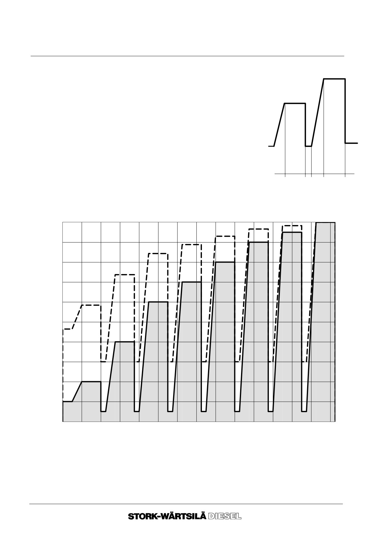
Manual
F 240
INSPECTION AND MAINTENANCE
4C TEST RUNNING
Explanation to figure 4.1 and recommended time:
4
-- a = gradual load increase
0,5 hr. minimum ;
-- b =
0,75 hr. to 1 hr ;
3
-- c =
0,2 hr. to 0,25 hr ;
-- 3, 4 etc.=
load step.
b
c
a
b
fig. 4.1
Graph A
Running--in programme for piston rings and cylinder liners. Propulsion:
[%]
8
7
100
6
5
4
90
3
80
2
70
1
60
50
40
30
20
10
0
0.00
1.00
2.00
3.00
4.00
5.00
6.00
7.00
8.00
9.00
10.00
11.00
12.00
13.00
14.00
t [hr.]
________
= Output
_____
= speed
Ver. 01
4 -- 19
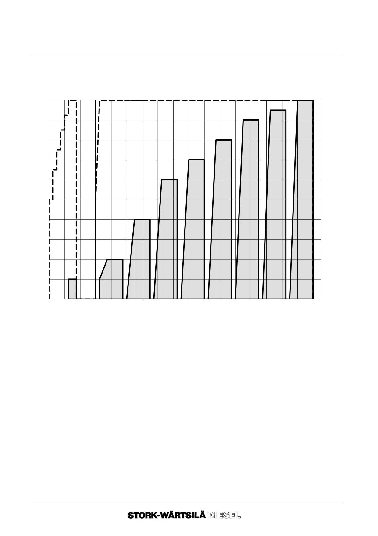
Manual
F 240
INSPECTION AND MAINTENANCE
4C TEST RUNNING
Graph B
Running--in programme for piston rings and cylinder liners. Generator operation:
[%]
9
100
8
7
90
6
80
5
70
4
60
50
3
40
30
2
20
1
10
0
--3.0
--2.0
--1.0
0.0
1.0
2.0
3.0
4.0
5.0
6.0
7.0
8.0
9.0
10.0
11.0
12.0
13.0
14.0
t [hr.]
________
= Output
_____
= Speed
3. Functional test
In some cases a functional test has to be carried out after engine trial and/or the run-
ning--in programme or total overhaul.
The functional test consists of:
-- starting the engine ;
-- increasing of load to minimum 80% of the stated load value ;
-- filling in the observation list (section 4A) as soon as the engine temperatures
are stable ;
-- comparing the values of the observation list with the values of the test report
and/or values of commissioning.
--o--o--o--o--o--
Ver. 01
4 -- 20
Manual
F 240
FUEL SYSTEM
5A INTRODUCTION
4. General
Good performance of a diesel engine greatly depends on the correct timing, correct
quantity and good atomisation of the fuel injection.
5. Description of
This paragraph is a general description of the function of engine parts in the fuel
engine parts
system.
The main parts of the fuel system are given in the general diagram (paragraph 5F).
These main parts have a number which corresponds to the number in the diagram.
This number is placed between brackets in the description below.
Fuel feed pump
The fuel system is standard equipped with an engine driven fuel feed pump, which is
(1.1)
fed from the day tank (starting tank), placed approximately 2m above the top of the
engine.
The fuel flows via the fine fuel filter and main fuel feed line to the high pressure fuel
pumps. The high pressure fuel pumps supply the fuel to the nozzles.
For a good filling of the high pressure fuel pump the capacity of the fuel feed pump is
approximately 4x higher than the full load consumption of the engine.
The surplus fuel flows from the high pressure fuel pumps into the return line to the day
tanks (starting tank).
The amount of heat collected by the fuel during passage through the high pressure fuel
pump must be dissipated by the return piping and the tank.
Fine fuel filter
The duplex fuel filter serves to remove impurities from the fuel, so that they cannot
(1.2)
enter the fuel system, and inflict damage on the high pressure fuel pumps or the
nozzles. The fuel filter consists of two compartments, each fitted with a filter element
which can be removed (also with the engine in operation).
This fine fuel filter is the last protection of the fuel injection equipment.
High pressure
The high pressure fuel pump pumps the fuel via the high pressure fuel line and the fuel
fuel pumps
injector into the cylinder. The high pressure fuel pumps are equipped with an oil barrier
(1.3)
system.
All fuel pumps have been calibrated accurately and provided with a sealed stop on the
fuel rack. The purpose of this stop is to limit the engine output. If this seal is broken
during the guarantee period, this may have as consequence, invalidation of the guar-
antee!
Ver. 01
5 -- 1
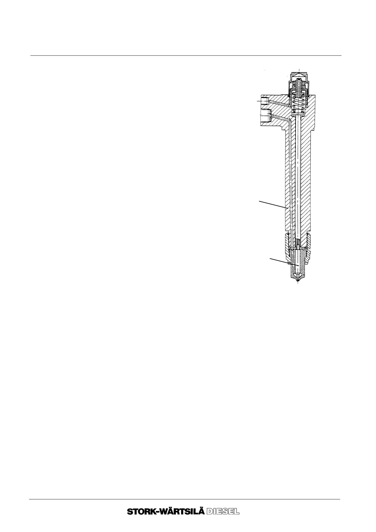
Manual
F 240
FUEL SYSTEM
5A INTRODUCTION
Fuel Injector
The main components of the fuel injector are:
(1.5)
-- nozzle holder ;
-- nozzle.
The nozzles are of the ”multihole type” and actuated
by the fuel pressure.
For maintenance, testing and adjusting of the open-
ing pressure, see chapter 17.
1
2
Pressure
The pressure regulating valve, placed at the end of the main fuel line, keeps the fuel
regulating valve
pressure constant, namely about 1.5 bar.
(1.6)
Leak--off fuel
The leak--off fuel coming from the nozzles is drained to the clean leak--off fuel tank.
(2.1,
2.2, and
The quantity mainly depends on the number of service hours of the nozzle tip, but the
2.3)
quantity of the leak--off fuel is not indicative of the quality of the nozzles.
The leak--off fuel of the nozzles is drained to the clean leak--off fuel tank.
This fuel can be supplied to the day tank without treatment.
Fuel leakage from renewal of the fuel filter elements will be collected via drains and
has to be stored in a dirty--oil tank (2.3).
--o--o--o--o--o--
Ver. 01
5 -- 2
Manual
F 240
FUEL SYSTEM
5B FUEL REQUIREMENTS
The MDO fuel that will be delivered to the engine must meet at least the following re-
quirements:
Bunker
-- viscosity at 40oC
max
11 cSt ;
requirements
-- specific mass at 15oC
max
0.90 g/ml ;
-- water content
max
0.3 % volume ;
-- sulphur content
max
2.0 % volume ;
-- ash content
max
0.01 % volume ;
-- sedimentation
max
0.07 % volume ;
-- cetane number
min
35 ;
-- carbon content (acc. Ramsbottom)
max
0.25 % ;
-- flashpoint
min
60oC ;
-- pout point, upper
summer
max
6 oC ;
winter
max
0 oC.
The above specifications also conform to :
-- Cimax --1990: DX, DA and DB ;
-- ISO 8217 F--DMX, DMA and DMB ;
-- (BSMA 100:1989 class M2).
If you want to use a fuel which does not meet the requirements, please consult
Stork--Wärtsilä Diesel.
Engine fuel
All fuel supplied to the engine must be properly cleaned from solid particles and water.
requirements
Attention!I
-- It is possible that some fuels contain ceresines, which, at a temperature below
50oC, change into solid particles. The fuel filter can become clogged with these
particles within a very short period of time. The best solution for this problem is
to heat up the fuel to minimum 50oC, so that the ceresines dissolve.
-- The values of the requirements are tested according to ASTM test methods.
-- If a fuel is bunkered with a water content higher then 0.2 % the water must be
separated from the fuel.
--o--o--o--o--o--
Ver. 01
5 -- 3
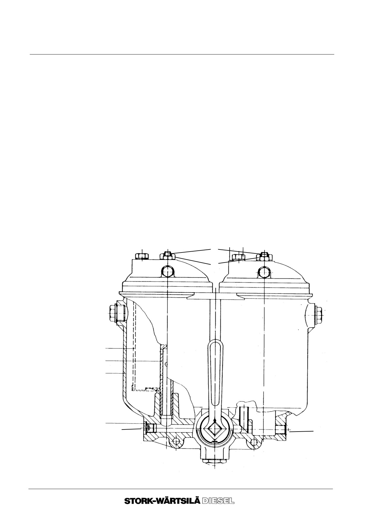
Manual
F 240
FUEL SYSTEM
5C FUEL FILTER ELEMENT
Before starting work, consult:
-- chapter
2, ”BACKGROUND INFORMATION”.
1.
General
The fuel filter consists of two compartments, each having one filter element.
The fuel filter has a 3--way cock permitting change--over during operation and the
fouled filter to be renewed.
2.
Removal
Only open the inactive filter compartment!
2. 1. Disengage the filter compartment with the fouled filter element.
The 3--way cock shows which filter compartment is active/inactive.
2. 2. Slacken the locking nut of vent screw A and open this screw.
2. 3. Drain the filter compartment by unscrewing drain plug B or the correspon-
ding plug in the drain line.
2. 4. Disconnect the vent line from the filter cover.
2. 5. Remove bolt C together with ring, filter cover and O--ring.
2. 6. Remove the filter element.
A
C
B
B
Ver. 01
5 -- 4
Manual
F 240
FUEL SYSTEM
5C FUEL FILTER ELEMENT
3. Fitting
3. 1. Clean the filter compartment and the cover with clean gasoil.
3. 2. Check the O--ring for damage. Replace it, if necessary.
3. 3. Check that the seat edges of the filter compartment and of the filter cover are
properly cleaned and undamaged.
3. 4. Fit the drain plug, using a new joint ring.
3. 5. Fit the new filter element.
3. 6. Fit an O--ring around the cover seat.
3. 7. Place the cover on the filter compartment and secure it, using bolt C.
3. 8. Screw the vent lines onto the filter cover.
3. 9. Put the 3--way cock in the central position. Once the filter compartment has
been vented, tighten the vent screw and lock it with the relevant nut.
Then switch to the desired filter compartment.
--o--o--o--o--o--
Ver. 01
5 -- 5
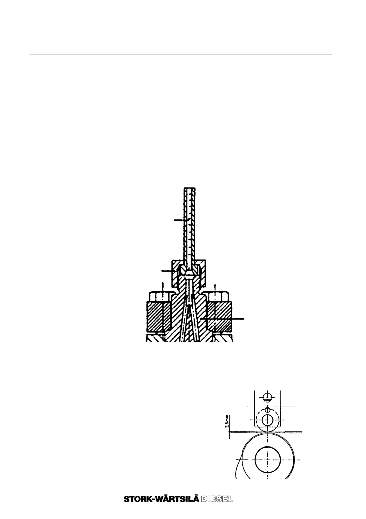
Manual
F 240
FUEL SYSTEM
5D INSPECTIONS, MOMENT OF INJECTION
Before starting work, consult:
-- chapter
2, ”BACKGROUND INFORMATION”.
1. Training tools
The following tools are used during the training course.
Tool A
Tool to check the beginning of the fuel injection.
Capillary tube
capillary tube
union nut
constant
pressure valve
Tool B
Adjusting plate for checking/adjusting the
pre--lifting of a new or overhauled H.P. fuel
pump.
cam follower
adjusting
plate
fuel cam
Ver. 01
5 -- 6
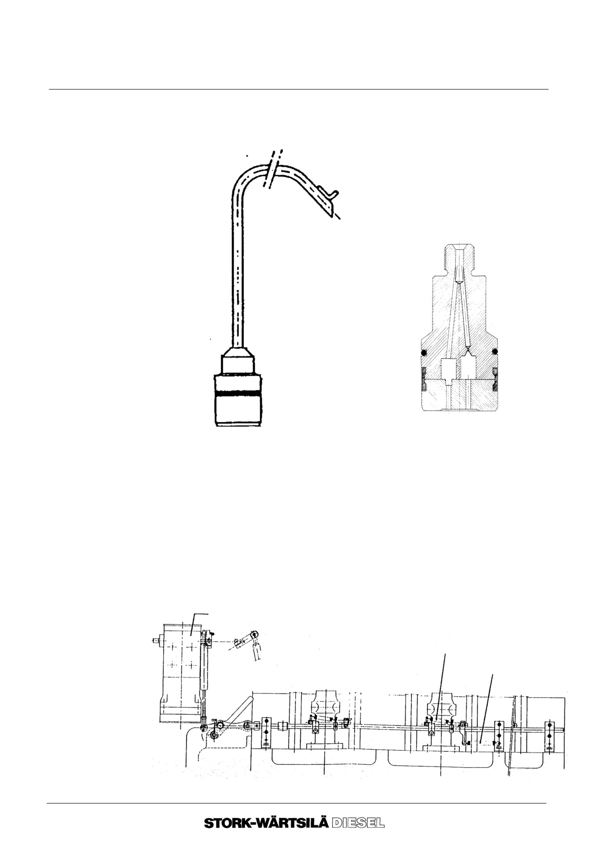
Manual
F 240
FUEL SYSTEM
5D INSPECTIONS, MOMENT OF INJECTION
Tool C dummy
The ”dummy” consists of a teflon model with the same dimensions as the constant
pressure valve, sealed by an O--ring or an old constant pressure valve with the inside
valves and springs removed.
EMPTY ”DUMMY”
TEFLON ”DUMMY”
2. Fuel Control
Examine the fuel control system for :
System
--
Smooth operation of the mechanism.
--
Rust and other deposits on the fuel pump control rods.
--
Wear and / or fracture of the fuel control return spring.
--
Wear and / or fracture of the springs between fuel pump control rods and
common fuel control shaft.
--
Proper condition of the pivoted joints and the linkage at the governor.
Lubricate the fuel pump control rods, pivoted joints, guide rollers, and common fuel
control shaft with a mixture of
50% lubricating oil and
50% gas
oil.
Governor
Spring between high pressure fuel pump
and control rod common fuel control shaft
Control rod tension spring
Ver. 01
5 -- 7
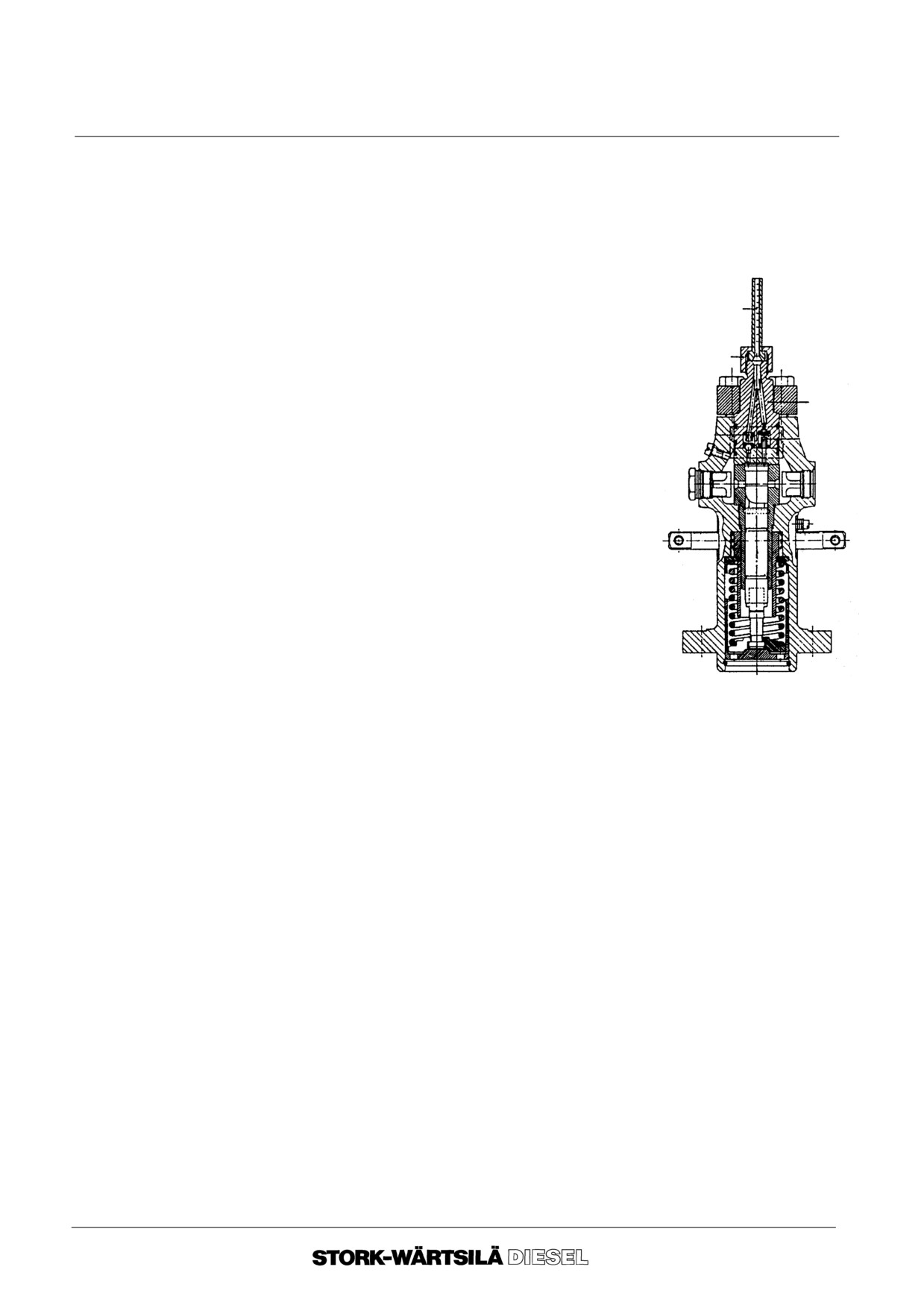
Manual
F 240
FUEL SYSTEM
5D INSPECTIONS, MOMENT OF INJECTION
3.
Verification of
moment of
injection
3.
1.
Disconnect the high pressure fuel line.
3.
2.
Fit the capillary tube with the union nut.
3.
3.
Move the fuel pump control rod to its full load
position.
Capillary tube
3.
4.
Turn the crankshaft until the crank of the
relevant cylinder is at 30o before T.D.C. of the
Union nut
compression stroke.
Constant
3.
5.
Turn the crankshaft in the direction of rotation
pressure
untill the fuel is seen to rise in the capillary tube
valve
(without air bubbles). This means that the fuel
passages in the constant pressure valve are
filled with fuel.
3.
6.
Turn the crankshaft back (against the direction
of rotation) until the crank of the relevant
cylinder is positioned at least 30o before T.D.C.
3.
7.
Turn the crankshaft slowly in the direction of
rotation and stop turning as soon as the fuel
rises in the capillary tube. At this point the
effective compression stroke begins. On the
flywheel the moment of injection can be found
and read off in crank degrees.
For the correct moment of injection see the value specified in the test bed report. The
tolerance allowed for the setting is 1o. If a greater variation is found, the pre--lifting
must be adjusted.
Ver. 01
5 -- 8
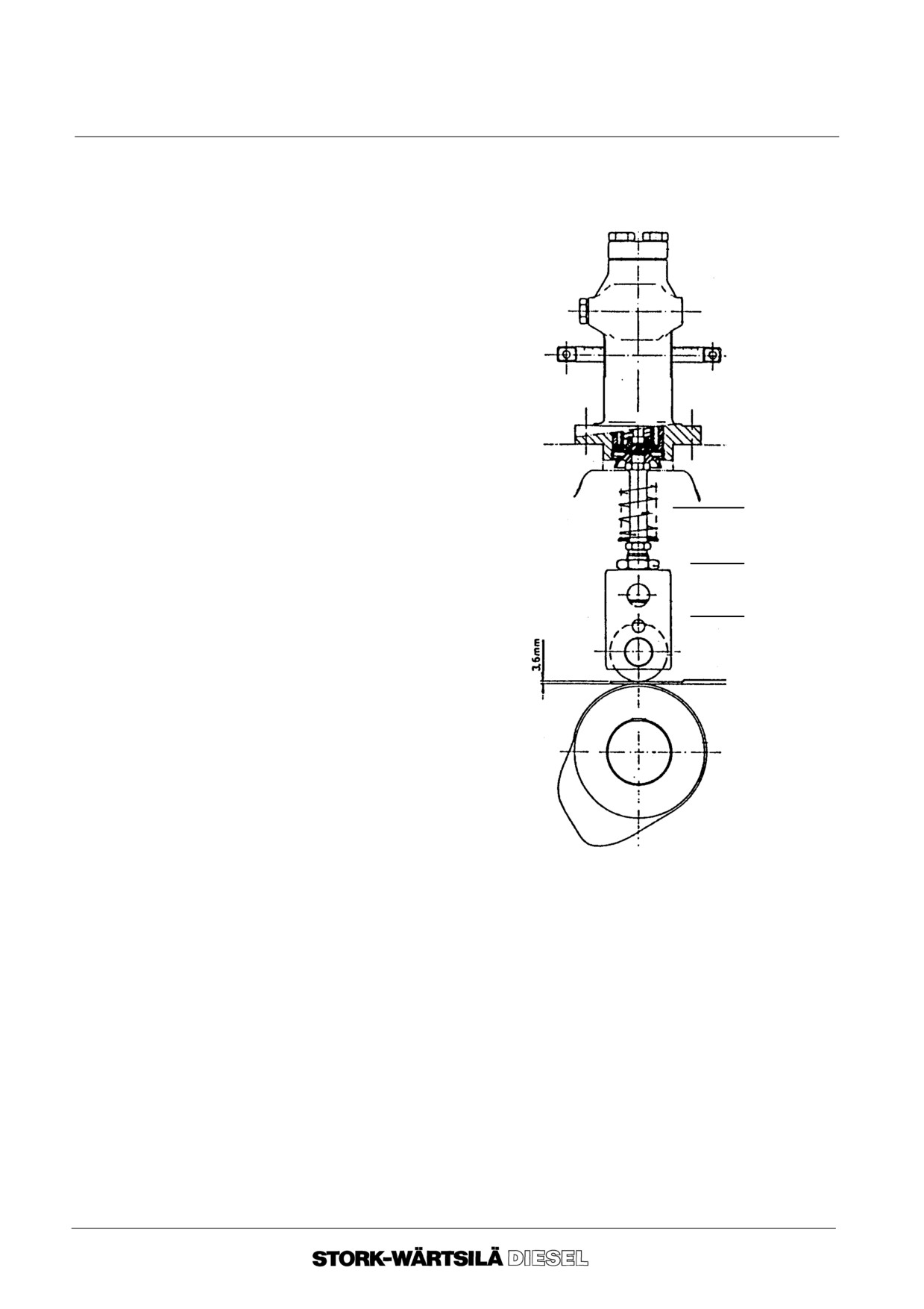
Manual
F 240
FUEL SYSTEM
5D INSPECTIONS, MOMENT OF INJECTION
4.
Checking
After fitting a new or reconditioned high pressure fuel pump, the pre lifting has to be
pre--lifting
checked and/or adjusted. Proceed as follows:
4.
1.
Close the fuel supply to the
engine.
4.
2.
Remove the camshaft
cover from the housing.
4.
3.
Turn the corresponding
fuel cam on its base circle.
4.
4.
Remove the constant
pressure valve and fit ”the
dummy.
4.
5.
Place a 3.6 mm adjusting
plate between the cam
follower and the base circle
Adjusting bolt
of the fuel cam.
4.
6.
Slacken the locking nut of
the fuel pump adjusting
Lock nut
bolt.
4.
7.
Bring the fuel control rod of
Cam follower
the fuel pump to its
maximum position.
Adjusing plate
4.
8.
Open the fuel supply to the
engine.
4.
9.
Turn the adjusting bolt
anti--clockwise until fuel
flows out of the ”dummy”.
Slowly turn the adjusting
bolt clockwise until fuel flow
out of the ”dummy” stops.
Next secure the bolt in
position by means of the
locking nut.
4.
10.Close the fuel supply and withdraw tool B and C.
Replace the constant pressure valve.
4.
11. Re--check the setting of the fuel timing, from point
3.6
and further.
4.
12.If the setting is outside the permitted tolerance the fuel cam position must be
corrected.
--o--o--o--o--o--
Ver. 01
5 -- 9
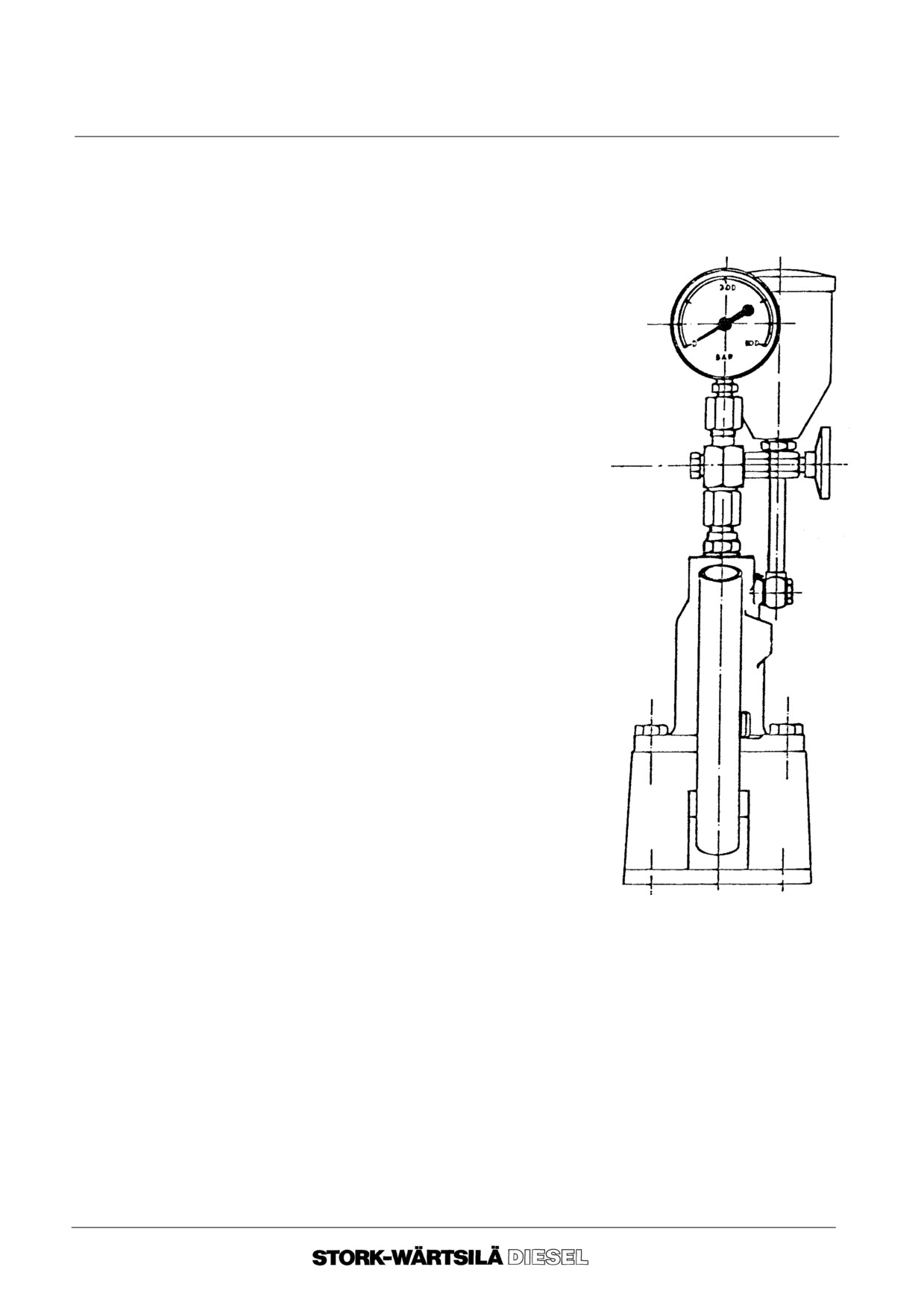
Manual
F 240
FUEL SYSTEM
5E CONSTANT PRESSURE VALVE
Before starting word, consult:
--chapter 2, ”BACKGROUND INFORMATION”.
1. TOOL
Tool for testing constant pressure valve.
Tool A
1
Testing pump
9612 SW 416
Tool B
Tool 66626 900, consists of:
--
Connecting pieces ;
--
Flexible high pressure lines (2x)
--
Manometers and non--return valve
Please contact the SWD Service Department
for ordering this tool.
2. Testing
2. 1. Check, if tool B is still under pressure at 120 bar, when the line is plugged off.
(If necessary, inspect the non--return valve of this tool).
2. 2. Remove the high pressure fuel line.
2. 3. Check if the fuel control rod is in zero position.
2. 4. Connect tools A and B to the high pressure fuel pump, with the help of tool A,
increase pressure to 120 bar.
2. 5. No go criteria is:
If the pressure drops from 120 bar to 80 bar within 5 seconds. In this case
renew the constant pressure valve.
--o--o--o--o--o--
Ver. 01
5 -- 10
Manual
F 240
FUEL SYSTEM
5F GENERAL DIAGRAM
Explanation of the item numbers in the diagram on the next page.
1. Fuel supply and
No. Name
return
1. 1. Engine driven fuel feed pump
1. 2. Duplex fine filter
1. 3. High pressure fuel pump
1. 4. High pressure fuel line, (not shown in the diagram)
1. 5. Fuel injector
1. 6. Pressure control valve
1. 7. Day tank (starting tank)
1. 8. Suction filter
2. Leak--off fuel
No. Name
2. 1. Leak--off line
2. 2. Clean leak--off tank
2. 3. Dirty leak--off tank
3. Miscellaneous
No. Name
3. 1. Storage tank
3. 2. Electrically driven fuel transfer pump
3. 3. Hand pump
3. 4. Duplex coarse filter
3. 5. Non return valve
Explanation of
LI
Level indication
letters
Ver. 01
5 -- 11
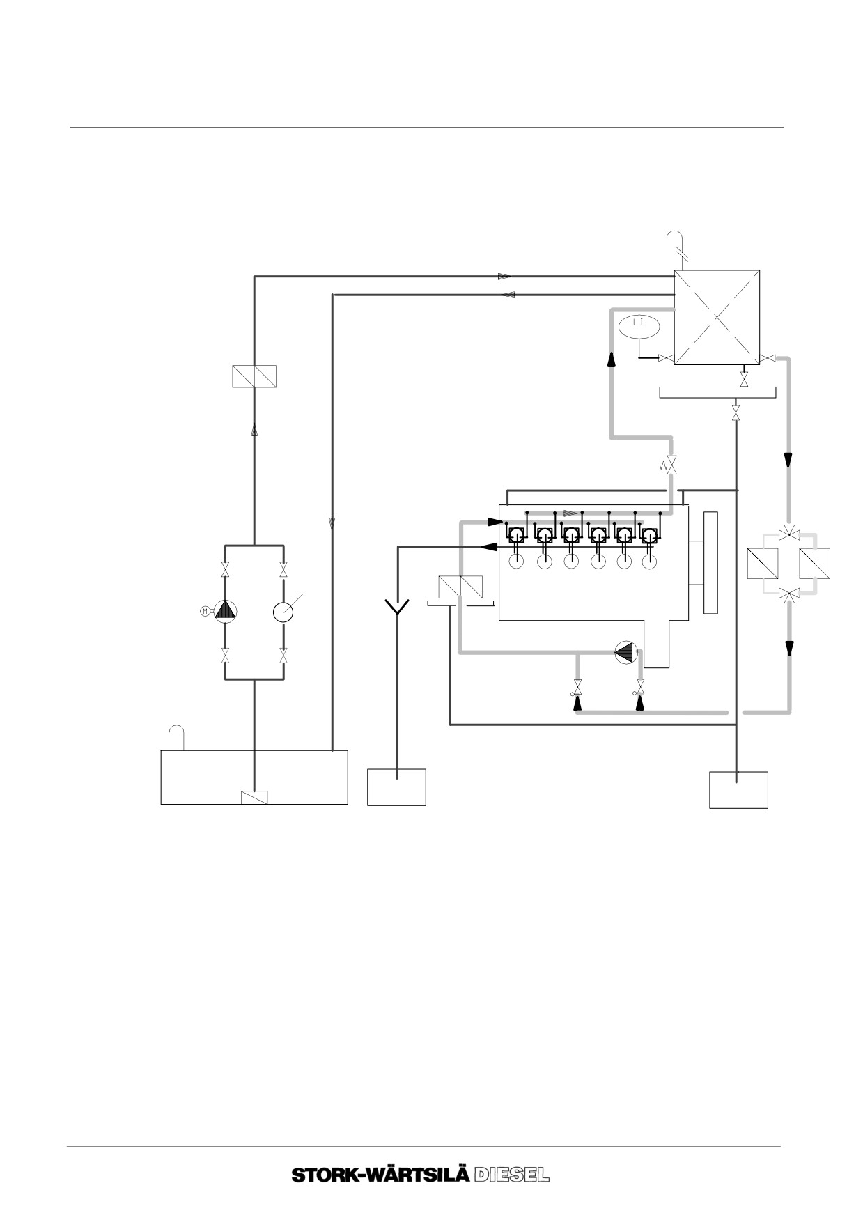
Manual
F 240
FUEL SYSTEM
5F GENERAL DIAGRAM
1.7
3.4
1.6
1.8
1.3
2.1
1.5
3.3
1.2
3.2
1.1
3.5
3.5
3.1
2.2
2.3
--o--o--o--o--o--
Ver. 01
5 -- 12
Manual
F 240
LUBRICATING OIL SYSTEM
6A INTRODUCTION
1. General
Lubrication of the engine takes place by means of an engine driven lubricating oil
pump. This self--suction pump draws oil, via a coarse filter, from the sump or a separate
oil tank. Subsequently the lubricating oil is pumped through a thermostatically
controlled three--way valve to the lubricating oil cooler or directly to the filter. After the
filter, the various engine parts are lubricated via a lubricating oil channel.
If the oil cannot run freely to the separate oil tank, because it is positioned higher than
the engine, a second engine driven pump is built on to return oil to the tank.
2. Description of
This paragraph is a general description of the function of engine parts in the lubricating
engine parts
oil system.
The main parts of the lubricating oil system are shown in the general diagram
(paragraph 6J). These main parts have a number which corresponds to the number
in the diagram. This number is placed between brackets in the description below.
Lubricating oil
Lubrication of the engine takes place by means of an engine driven lubricating oil
pump
pump. This self--suction pump is a vanes pump.
(1.0).
Thermostatic
The lubrication oil temperature is regulated by a thermostatically controlled three--way
three--way valve
valve. This regulates the amount of oil going through the lubrication oil cooler, from
(1.2)
which it is returned to the engine.
At a cold start almost all the oil will passsing by the cooler. At a higher temperature,
a part of the oil will flowing through the cooler, and at a temperature higher than the
setting of the valve, practically all the oil will flowing through the cooler.
The max. temperature of the lubricating oil in the sump is about 85oC.
Safety overflow
A safety overflow valve is fitted before the filter in the thermostatic valve housing in
valve (1.3)
order to prevent filter elements from breaking because of excessively high pressure,
due to fouled filter elements. If the pressure becomes too high, the valve will open,
returning the excess oil to the engine sump.
Pressure
A pressure regulating valve controling the oil pressure, is fitted after the filter and
regulating valve
before the main lubricating oil manifold. As soon as the oil pressure becomes too high,
(1,6)
the ”superfluous” oil flows, via the pressure regulating valve, back to the engine sump.
As soon as the lubrication oil pressure is too low the pressure alarms will be activated.
Ver. 01
6 -- 1
Manual
F 240
LUBRICATING OIL SYSTEM
6A INTRODUCTION
Main lubricating oil
From the main lubricating oil manifold via lubrication oil pipes oil is supplied to the
manifold (1.7)
crankshaft and the connecting rods, the main, big end and gudgeon pin bearings. The
main lubricating oil also effectets the cooling of the pistons through the main lubricating
oil manifold, as well as lubrication of the gears for the camshaft drive and pump
housing. The lubrication oil lines, also connected to this main lubricating oil manifold,
supply oil to the other engine parts, the most important being:
-- the bearings of the VTC turbocharger, if fitted ;
-- axial locating rings and the bearings for the camshaft ;
-- the intermediate gearwheel for the camshaft drive ;
-- the rollers and parts for the valve lever mechanism ;
-- the bearings of the valve levers, as well as valve stems and bridge pieces ;
-- the governor drive ;
-- the supply to the valve seat lubricators ;
-- the supply to the oil barrier of the fuel pumps.
Pre--lubrication
A manually operated prelubrication pump is inserted in the circuit in order to be able
pump (4.0)
to fill the entire lubricating oil circuit and to prelubricate all engine parts before starting
the engine. The stand--by pump (if present) can take over this function.
Needle valve (5.6)
The needle valves are fitted for use during maintenance and repair of the measuring
instruments between or after the valves.
Crankcase venting
In order to avoid overpressure in the crankcase the engine is fitted with an air vent,
(A)
connection of which must be completed during the installation of the engine. At its
lowest point it must have a means of draining.
--o--o--o--o--o--
Ver. 01
6 -- 2
Manual
F 240
LUBRICATING OIL SYSTEM
6B LUBRICATING OIL REQUIREMENTS
1. General
NonnThe lubricating oil must have a number of physical and chemical properties,
generally required for satisfactory operation in medium speed diesel engines.
Since Stork--Wärtsilä Diesel neither manufactures nor supplies oil, Stork Wärtsilä
Diesel does not control or know the complete composition of a lubricating oil brand,
type or batch and therefore cannot give any guarantee that a lubricating oil brand, type
or batch will behave satisfactorily under all operating conditions.
It is the duty of the engine user to monitor the behaviour of the lubricating oil carefully
and regularly in order to ensure that engine remains in good condition.
2. Engine
Lubricating oil for lubrication of bearings, pistons, valve gear and gearwheels.
lubricating oil
The lubricating oil must meet the following requirements:
--
The API class CD or US--Army--Mil--L--2104C, specifications.
--
The lubricating oil must be suitable for continuous cleaning by a centrifugal
separator (in by--pass). The lubricating oil inlet temperature for the separator is
to be controlled between 800C and 900C.
--
For the purpose of cleaning the lubricating oil by means of the centrifugal
separator the lubricating oil must have a high demulsifying ability. This is
particularly important whenever there is a possibility of contamination by sea
water.
--
Viscosity
SAE 40 ;
--
Flash point above
2200C ;
--
Point of solidification max
--120C * ;
--
Alkalinity
TBN , (ASTM 2896 has to be corrected for the
sulpher contents of the used fuel. **)
--
The quantity of lubricating oil in the lubricating oil system:
With MDO--use it is 0.7 litres per kW output, as shown on the engine type plate.
If in accordance to specifications lower values have to be used, this will reduce
the effective life of the oil.
* In case the ambient temperature is extremely low, the point of solidification must
be at least 90C below the lowest temperature at which the oil is expected to
be used.
** TBN = Total base number.(mg KOH/g lubricating oil) = 5 + 6
times sulphur percentage of the fuel. When a distillate fuel is continuously used
with a sulphur content well below 1%, a lubricating oil with a TBN 5--10 can be
applied.
3. Sub--suppliers
The lubricating oil required for various engine parts, such as turbocharger and
Manuals
governor is specified in the respective sub--suppliers manuals.
Ver. 01
6 -- 3
Manual
F 240
LUBRICATING OIL SYSTEM
6B LUBRICATING OIL REQUIREMENTS
4. Testing engine
When testing the quality of the lubricating oil for the engine the specifications and
lubricating oil
instructions of the oil supplier have to be observed.
Under normal operating conditions samples of lubricating oil should be taken in
accordance with the maintenance schedule. On the basis of the results of the tests to
be carried out by the oil supplier it can be determined whether the lubricating oil is
suitable for further use. It is also recommended to subject these samples to a special
analysis in order to watch the wear development of various engine components. It is
a good habit to test the oil for the presence of water every week.
Beside the lubrication function the engine lubrication oil must also prevent oxidation
products coming from fuel and lubricating oil depositing on engine parts and keep
these oxidation products well dispersed. The oxidation products are only partly
removed from the lubricating oil by the lubricating oil filter. This ultimately requires
replacement of the lubricating oil. The replacement intervals depend on the operating
conditions and the efficiency of the lubricating oil treatment and the quantity of oil in
circulation.
5. No--Go criteria for
A sudden increase in sludge or carbon deposits in the crankcase or camshaft housing
engine
indicates that the quality of the lubricating oil has deteriorated.
lubricating oil
Before one of the criteria below has been reached the lubricating oil can be brought
back to normal condition in some cases.
With shorter intervals between cleaning of the separator it is possible to intensify
separation and thus decrease water and insolubles to within specification. Always
consult the lubricating oil supplier.
No Go criteria
--
rate of change of viscosity
--20/+20% ;
--
flash point
below 1800C ;
--
pentane insolubles
above 2.5% ;
--
toluene insolubles
above 2 % ;
--
pentane insolubles minus toluene insolubles
above 0.5% ;
--
water content
above 0.2 % ;
--
TBN
below 60% of original value.
--
Spectral analysis.
If the results of the lubricating oil analysis show that the no--go criteria are exceeded
it is recommended to condemn the lubricating oil. The specifications of the oil supplier
are to be adhered to.
--o--o--o--o--o--
Ver. 01
6 -- 4
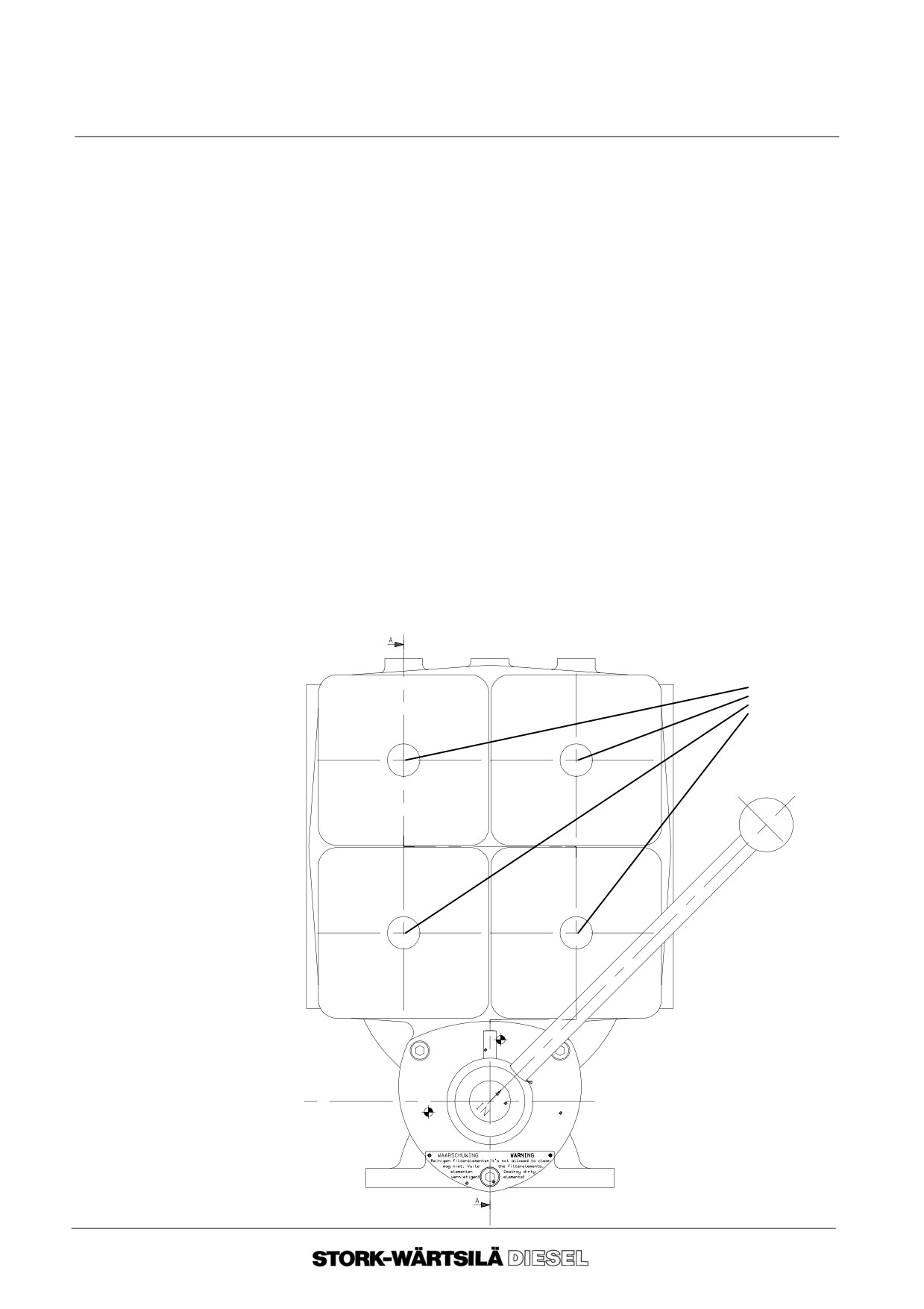
Manual
F 240
LUBRICATING OIL SYSTEM
6C LUBRICATING OIL FILTER
1. General
The lubricating oil is filtered before it enters the engine.
The lubricating oil filter has four filter compartments. The filter compartments are
connected in pairs. Two of the four compartments are always in use.
The magnetic core of the filter, and the element are both attached to the cover, so that
these can be withdrawn together.
Filter elements may not be cleaned, but must always be renewed.
During operation compartments can be changed over by means of a change--over
valve and the lubricating oil of the non--active compartment can run freely to the engine
sump.
The lubricating oil filter comes with a built--on differential pressure indicator as
standard.
As soon as the differential pressure indicator indicates that the active filter
compartments are fouled, renew all dirty filter elements. For correct indication the
lubricating oil temperature must be more than 50 C.
When the change--over valve handle is positioned as below, the right hand filters (CC)
are in operation, and the left hand filters can be renewed. When the change--over valve
handle is over to the left, the left hand filters (BB) are in use, and the right hand filters
can be renewed.
The control plug (A) securing the lids, leaks if the working filter is accidentally opened.
A
B
C
B
C
Ver. 01
6 -- 5
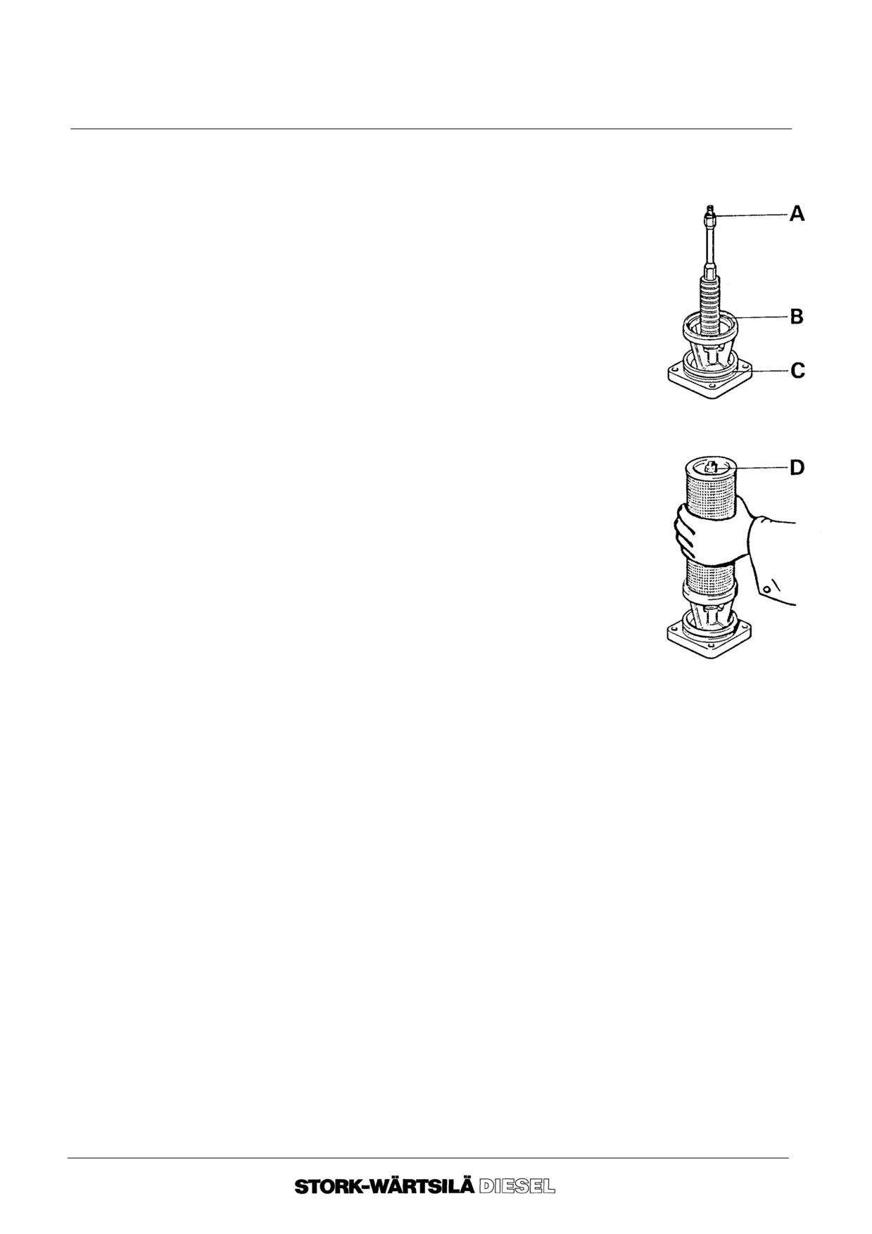
Manual
F 240
LUBRICATING OIL SYSTEM
6C LUBRICATING OIL FILTER
2. Replacing
Open only filter compartments that are not in use!
2.
1.
Clean the upper surface of the filter housing and
the filter covers, so that no dirt can fall into the
compartments during removal.
2.
2.
If you have to change the oil circuit,wait some time
to allow the oil pressure and the lubricating oil level
in the non--active filter compartments to drain
sufficiently.
2.
3.
Remove the filter covers, complete with the filter
elements, from the compartments (that are not
active).
2.
4.
Cover the open filter compartments.
2.
5.
Remove the dirty filter elements from the filter
covers.
2.
6.
Inspect the magnetic cores and the insides of the
filter elements for dirt and metallic particles that
may give an indication of abnormal wear of engine
parts.
2.
7.
Destroy dirty filter elements after
inspection!
3. Assembly
3.
1.
Carefully clean the filter cover and the magnetic
core and remove the used rubber rings.
3.
2.
The outside of the filter element is the “clean oil side”, so be sure to keep it
clean during assembly.
3.
3.
Check whether the seat edges of the filter housing and the filter cover are
clean, and fit new rubber rings A, B and C.
3.
4.
Place the new filter element on rubber ring B and fit nut D, together with a
washer.
Tighten nut D until the filter element can just be turned manually.
3.
5.
Make a mark on the nut and the filter element and then tighten the nut by one
full turn.
3.
6.
Place the new filter unit back into the filter housing; use a plastic hammer or
light blows with the hand to position it correctly. Tighten the nuts crosswise
and uniformly, using normal spanner force.
--o--o--o--o--o--
Ver. 01
6 -- 6
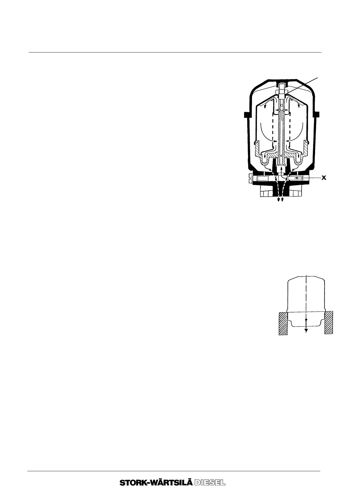
Manual
F 240
LUBRICATING OIL SYSTEM
6D CENTRIFUGAL FILTER
1. General
The use of the centrifugal filter increases the lifetime of the filter elements.
C
The working of the filter is based on centrifugal
force.
The engine lubricating oil is pumped into the
filter through passage “x” and passes upwards
through the hollow shaft before flowing into the
rotor.
The rotor rotates by means of the reaction force
of the oil jet coming from two nozzles in the
rotator bottom. The rotor rotates at high speed,
throwing particles of dirt outwards against the
inserted filter paper. The filtered oil flows
through the holes in the stand-pipe to the
nozzles and then back into the sump.
2. Disassembly
With the engine running, close the valve in the supply line to the centrifugal filter.
For disassembly see the exploded view of the centrifugal filter on page 6--8.
2. 1. Remove clamp A.
2. 2. Remove filter cover B.
2. 3. Lift the complete rotor and allow the oil to leak into the filter housing.
2. 4. Remove the complete rotor.
2. 5. Removing the insert paper:
-- Remove nut C and remove the hollow shaft from the rotor ;
-- Place the rotor on 2 blocks of wood ;
-- Pull the rotor housing loose from the cover ;
-- Remove the inserted filter paper together with
the compressed dirt particles.
With the engine running, close the valve in the supply line to the centrifugal filter.
3. Replacement
For assembly see the exploded view of the centrifugal filter on page 6--8.
3. 1. Clean all parts carefully.
3. 2. Check whether the nozzles in the rotor housing are open.
3. 3. Check whether the passage in the hollow shaft is free of dirt, and check the
bearing journals for wear or damage.
3. 4. Remove the reducing valve D from the filter housing, clean it and check
whether it can be moved freely. Re--assemble it.
Ver. 01
6 -- 7
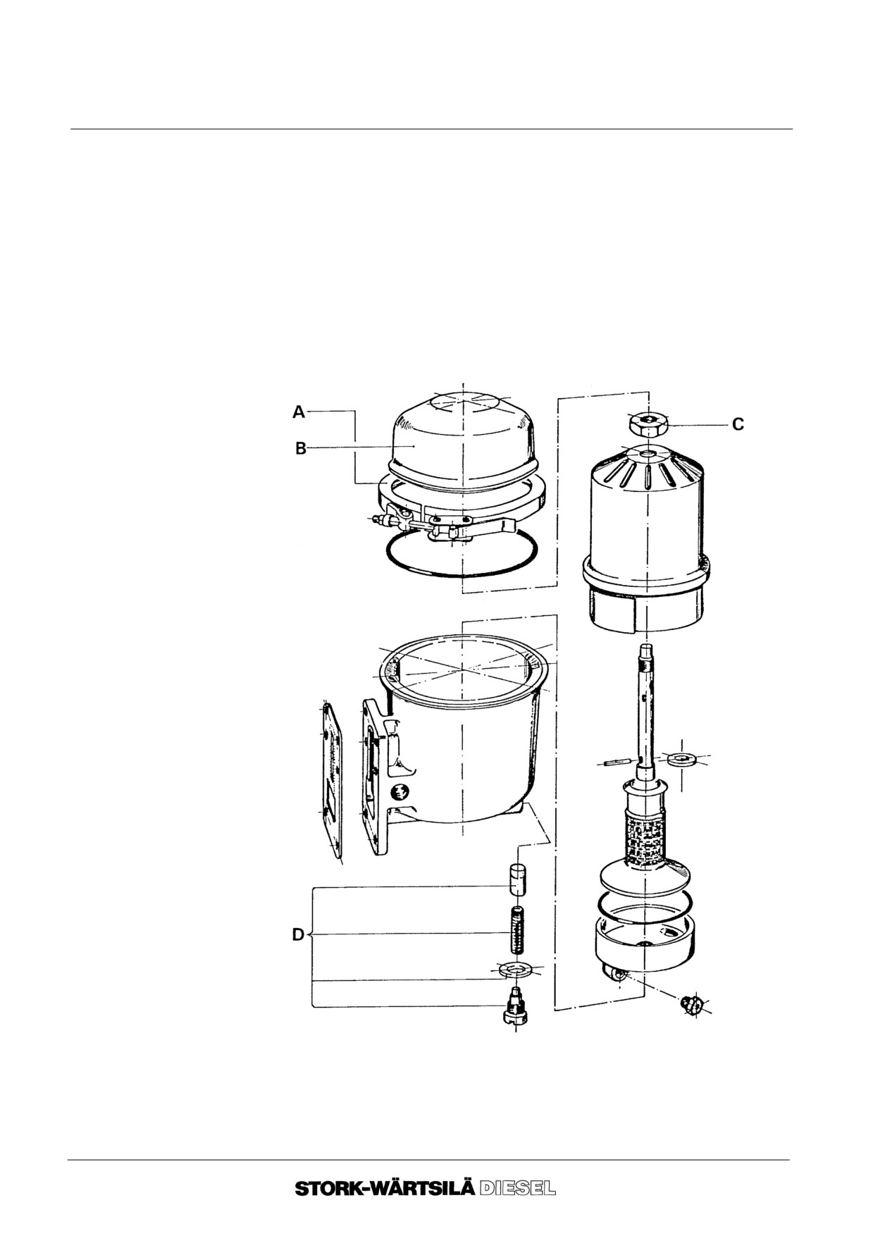
Manual
F 240
LUBRICATING OIL SYSTEM
6D CENTRIFUGAL FILTER
3. 5. Check whether the O--rings are damaged; if so, renew them.
3. 6. Insert new filter paper into the rotor cover.
3. 7. Assemble the rotor together and turn nut C hand tight. Turn nut C 180o
futher.
3. 8. Fit the complete rotor into the filter housing and check that it can rotate freely.
3. 9. Fit the filter cover B and clamp A.
3. 10.Open the valve in the supply to the filter.
3. 11. Check all connections after the filter has been taken into operation.
--o--o--o--o--o--
Ver. 01
6 -- 8
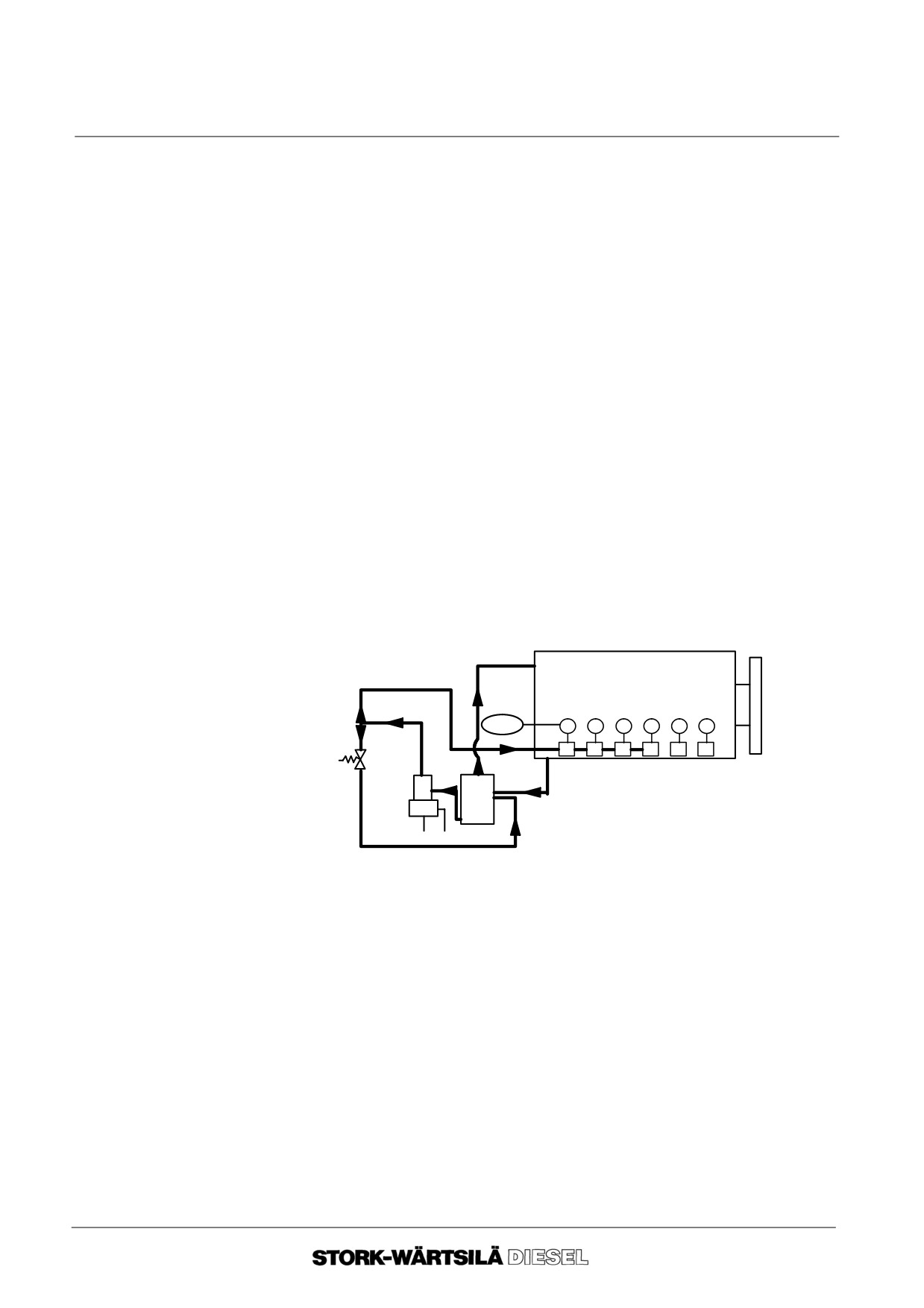
Manual
F 240
LUBRICATING OIL SYSTEM
6E LUBRICATION OF INLET VALVE SEATS
1. General
To minimize wear of inlet valves and inlet valve seats some oil is automatically supplied
to the air inlet duct just before the inlet valves. The oil is atomized by the charge air,
passing with high speed through the air inlet duct.
The lubricating oil in container C, will be kept at a constant level by means of an
overflow which is connected to the crankcase. The lubricating oil to the dosing valves
B will be supplied by pneumatic plunger pump D.
When running an engine on low load the charge air pressure is low and the lubrication
will be switched off automatically by pressure switch A.
Pneumatic plunger
When the plunger is pressed upwards by means of compressed air, the oil will be
pump
forced into the delivery line via the non--return valve. When the plunger piston
(D)
descends, oil from the delivery line will flow back via the ball valve until the delivery
line has been relieved of pressure.
Dosing valve
The oil supplied by the pneumatic pump will force a plunger in dosing valve B down
(B)
against the pressure exerted by a spring. This enables the oil to reach the valves via
the non--return valve. As the plunger ”floats” in the dosing valve tanks to a loose fit,
oil can return to the inlet side when the spring pressure causes the plunger to ascend
after the delivery stroke of pneumatic plunger pump D.
2. Checking
A
B B
B
B B B
D
C
2. 1. Run the engine under load so that the charge air pressure is higher than 0.8
bar. The inlet valve lubricating system is activated by switch A.
2. 2. Disconnect the oil supply line after dosing valve B on cylinder 1.
2. 3. If the system functions properly, a small amount of oil will emerge from the
dosing valve every 20 seconds.
2. 4. Reconnect the oil supply line to the dosing valve.
--o--o--o--o--o--
Ver. 01
6 -- 9
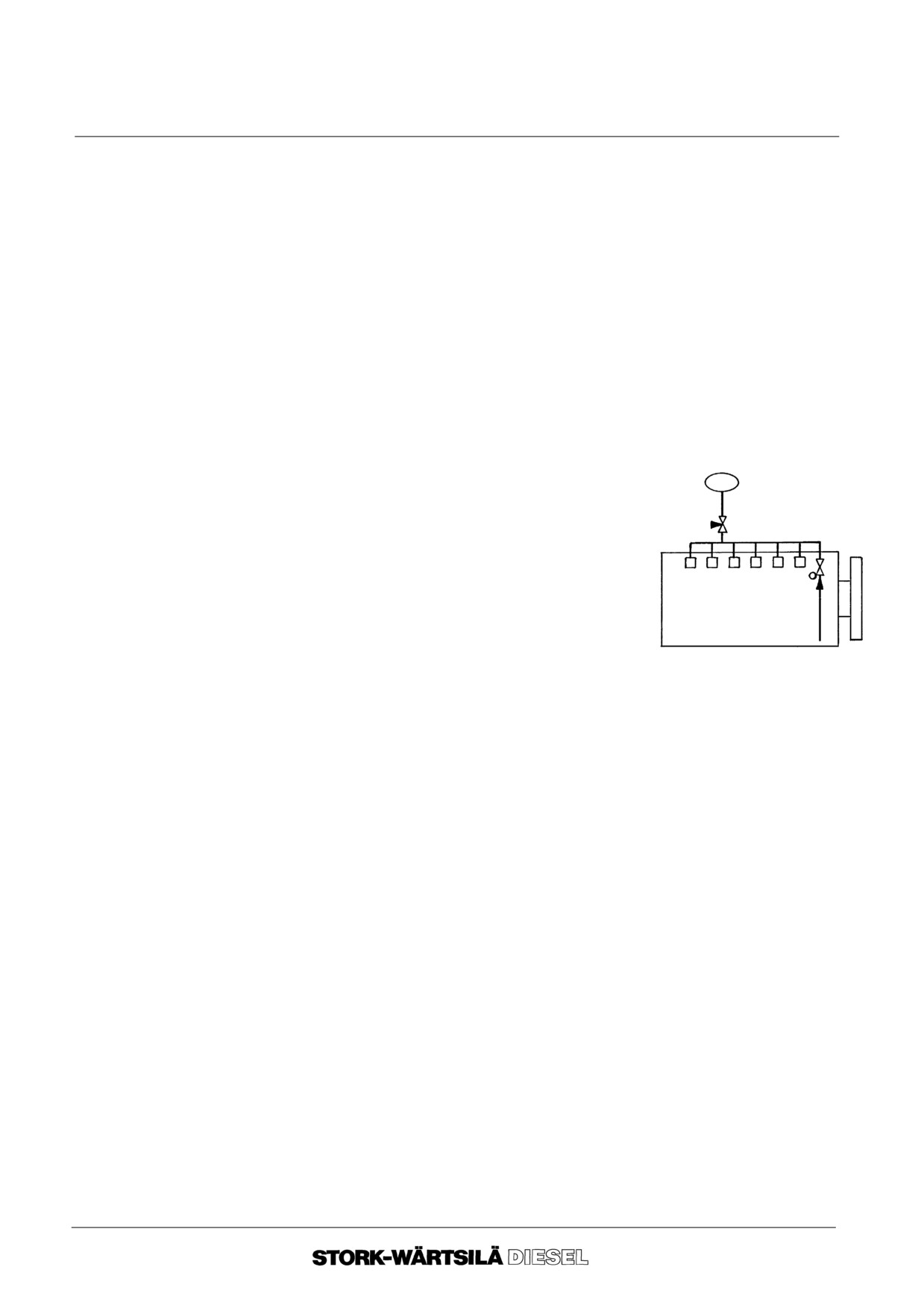
Manual
F 240
LUBRICATING OIL SYSTEM
6F BARRIER OIL SYSTEM HIGH PRESSURE
FUEL PUMPS
1. General
The barrier oil system for the HP fuel pumps (if applicable) forms part of the main oil
lubrication system.
In order to prevent fuel leaking along the plungers into the camshaft housing, a groove
around the plunger piston is filled with lubricating oil under pressure. The pressure of
this lubricating oil is higher than the fuel supply pressure.
This sealing is called the barrier oil system.
The barrier oil also lubricates a part of the plunger piston.
Attention!
Shut off the fuel supply to the engine when the engine is not in operation for a long
period and when the barrier oil system is not pressurized by a pre--lubrication pump.
2. Checking the
barrier oil system
HP fuel pumps
2. 1. When the engine is in operation, the
pressure indicators for engine lubricating
oil and barrier oil pressure must have
practically the same readings.
2. 2. Stopping the engine.
The pointer of the barrier oil pressure indicator
may not fall noticeably.
--o--o--o--o--o--
Ver. 01
6 -- 10
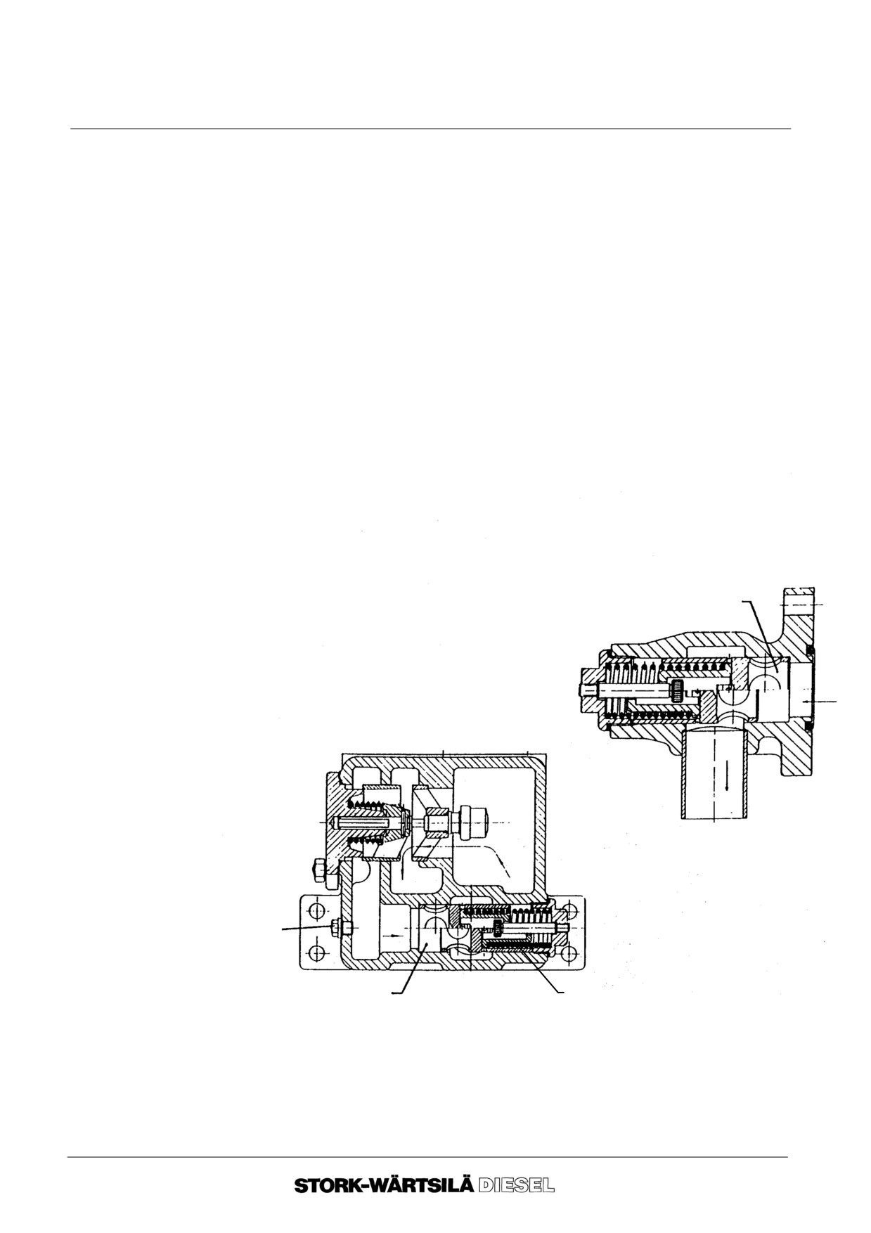
Manual
F 240
LUBRICATING OIL SYSTEM
6G INSPECTIONS
1. Lubricating Oil
The lubricating oil system includes two overflow valves, namely :
Overflow Valves
--
Safety overflow valve
(before lubricating oil filter, setting + 5 bar)
--
Pressure regulating valve
(after the lubricating oil filter, setting +3 bar)
One side of the overflow valve is exposed to the lubricating oil pressure, while a spring
Working Principle
force acts on the other. As long as the spring force exceeds the force exerted by the
oil pressure, the valve remains closed. If the latter force becomes greater than the
spring force, the valve will open and release the oil into the oil sump.
Removal
1. 1. Close the valve of the lubricating oil tank, (if applied).
1. 2. Drain the lubricating oil through the drain plug in the lubricating oil thermostat
housing.
1. 3. Turn the springholder out of the thermostatic housing and remove the valve.
Inspection
1. 4. Check the sealing ring. Renew if necessary.
Pressure regulating valve
1. 5. Check the valve for fretting and other
flaws.
If necessary, polish the
surface with a fine emery cloth and
clean it.
1. 6. Check that the valve operates
smoothly. Renew any worn parts if
necessary.
Drain plug
Safety overflow valve
Spring holder
--o--o--o--o--o--
Ver. 01
6 -- 11
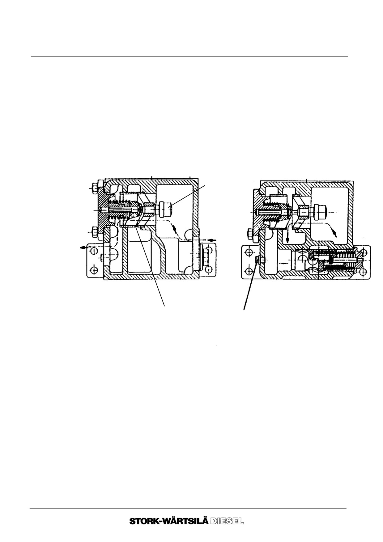
Manual
F 240
LUBRICATING OIL SYSTEM
6H LUBRICATING OIL THERMOSTATS
1. General
The thermostat three--way valve is equipped with two elements. In a cold condition,
the thermostatic elements are closed and hardly no oil flows through the heat
exchanger. When the temperature of the oil rises, the wax elements expand, and
causes the element to open against spring pressure, so that the passage to the heat
exchanger is released.
If the oil becomes excessively hot or remains too cold, the two thermostatic wax
elements must be examined.
Thermostatic three--way valve
in cold condition
in warm condition
Wax element
Valve
Drain plug
2. Inspection of the
thermostatic wax
elements
2. 1. Drain the lubricating oil by removing the drain plug from the thermostat
housing (proceed carefully when the engine is still hot).
2. 2. Remove the thermostat covers.
2. 3. Place the wax element in a basin filled with water. Heat the water and with
the aid of a calibrated thermometer check whether the element opens at the
correct temperature. If the element does not open at the correct
temperature, it must be renewed.
2. 4. Refit all parts in the reverse order.
--o--o--o--o--o--
Ver. 01
6 -- 12
Manual
F 240
LUBRICATING OIL SYSTEM
6J GENERAL DIAGRAM
Explanation of the item numbers in the diagram.
1. Main lubricating
No.
Name
oil flow
1.
0.
Engine driven lubricating oil pump
1.
1.
Non return valve
1.
2.
Thermostatic three--way valve
1.
3.
Lubricating oil cooler
1.
4.
Change--over filter
1.
5.
Pressure regulating valve
1.
6.
Main lubricating oil manifold, engine
1.
7.
Oil tank
1.
8.
Coarse filter
1.
9.
Safety overflow valve
2. Lubrication inlet
No.
Name
valve seats
2.
1.
Oil reservoir
2.
2.
Pneumatic pump
2.
3.
Dosing valve (to air inlet)
2.
4.
Overflow valve
2.
5.
Air inlet duct
3. Oil barrier
No.
Name
HP--fuel pump
3.
1.
High pressure fuel pumps
3.
2.
Non return valve
4. Pre--
No.
Name
lubrication
4.
0.
Electrically driven pre--lubrication pump
system
4.
1.
Overflow valve, (build in pre--lubrication pump)
(optional)
4.
2.
Non return valve
4.
3.
Coarse filter
5. Miscellaneous
No.
Name
5.
1.
Valve
5.
2.
By--pass centrifugal filters
5.
3.
Non return valve
5.
4.
Manual pre--lubrication pump
5.
5.
Coarse filter
5.
6.
Needle valve
Explanation
A
Crankcase de--aeration
letters
LS
Level switch
PDI
Pressure differential indicator
PI
Pressure indicator
PS
Pressure switch
TI
Thermometer
TS
Temperature switch
Ver. 01
6 -- 13
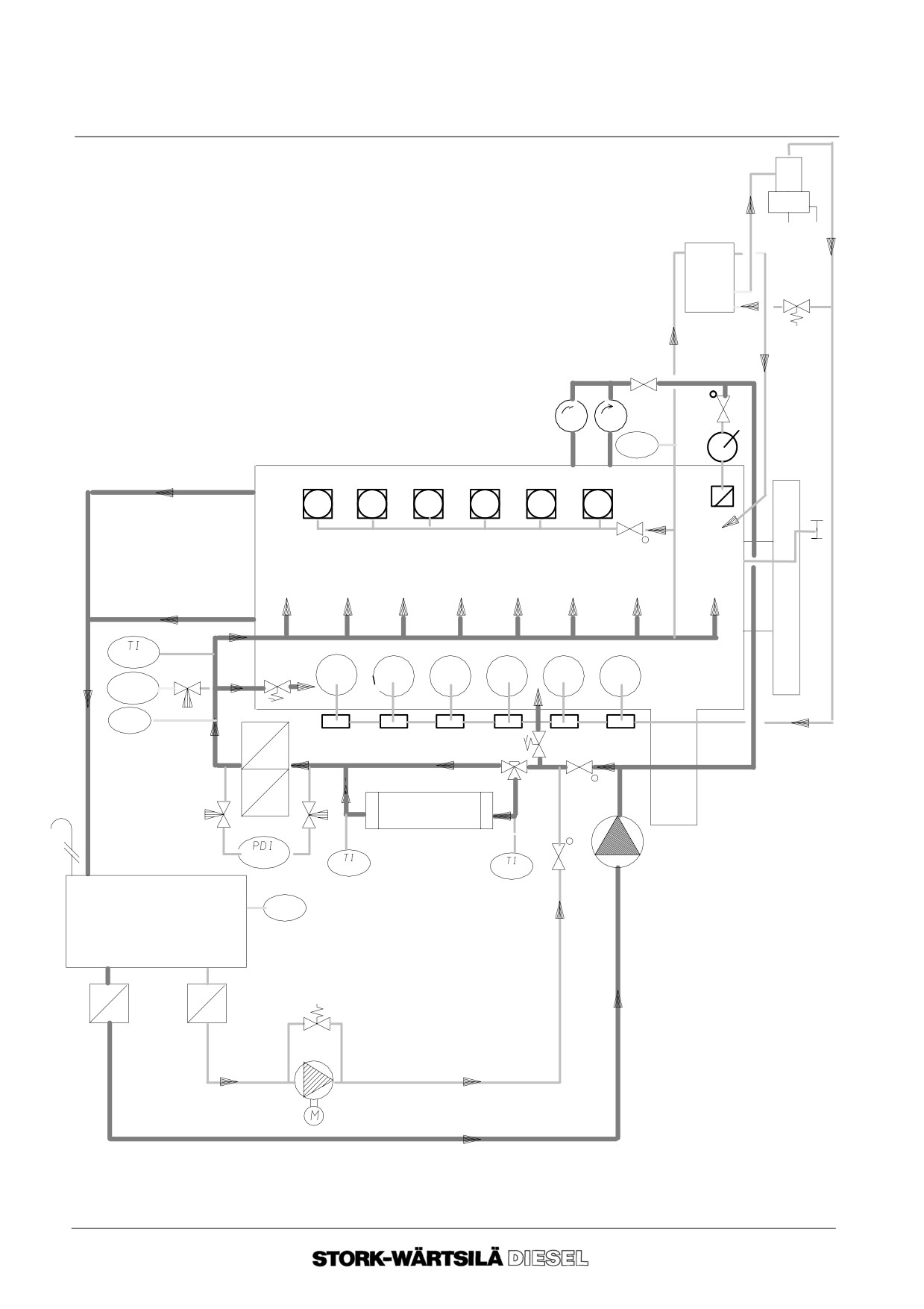
Manual
F 240
LUBRICATING OIL SYSTEM
6J GENERAL DIAGRAM
6. General Diagram
2.2
2.1
2.4
5.1
5.3
5.2
5.4
PI
5.5
3.1
A
3.2
1.6
5.6
1.5
2.5
PS
TS
1.4
2.3
1.9
1.2
1.1
1.3
4.2
1.0
LS
1.7
4.1
1.8
4.3
4.0
--o--o--o--o--o--
Ver. 01
6 -- 14
Manual
F 240
COOLING WATER SYSTEM
7A INTRODUCTION
7.
General
During the combustion process in the engine, heat is transfered to various engine
parts. To protect these parts against overly high temperatures it is necessary to
dissipate the heat by means of cooling water systems.
This paragraph is a general description of the function of engine parts in the cooling
water system.
The main parts of the cooling water system are shown in the general diagram (para-
graph 7H). These main parts have a number which corresponds to the number in the
diagram. This number is placed between brackets in the description below.
8.
Description of
The cooling process (= heat dissipation) consists of two separate systems, namely the
engine parts
high temperature system (HT--circuit) and the low temperature system (LT--circuit).
HT--circuit
(Other system combinations are also possible).
To prevent the forming of rust and scale in the cooling water system, an inhibitor must
be added.
The HT--circuit includes the engine and if a two stage air cooler is fitted, the first stage
of the air cooler.
Cooling water
The cooling water pump is an engine driven centrifugal pump, that circulates the water
pump (1.0)
through the HT--circuit. The cooling water pump is built onto the gear box as standard
and is driven by the crankshaft through gear transmission.
Valves directly before and after the cooling water pump have to be used in case of
emergency operation.
The cooling water pump pushes the cooling water via the cooling water inlet manifold
(1.1), through the engine block, the turbocharger and, if applied, through the first stage
of the air cooler. From the engine the cooling water flows through the cooling water
outlet manifold (1.2) to the thermostatic three--way valve.
De--aeration
De--aeration points connections are provided on the cooling water outlet manifold (1.2)
points (1.3)
of the engine and on the cooling water outlet pipe of the turbocharger (1.3).
For checking of the de--aeration, consult section 7C.
Thermostatic
The thermostatic three--way valve controls the outlet temperature of the cooling water.
three--way valve
Depending on this temperature the cooling water flows back to the engine (by--pass),
(1.4)
or via the cooling water cooler to the engine.
For maintenance and checking, consult section 7E.
Water cooler
A heat exchanger (cooler) is used to dissipate the heat of the HT--circuit. The heat
(1.5)
exchanger can vary per installation.
For maintenance, consult section 7D.
Cooling water
The purpose of the expansion tank is to compensate volume changes in the cooling
expansion tank
water system and it also serves to vent the system and to provide sufficient static
(1.7)
pressure.
Emergency
In the HT--circuit a valve is provided after the cooling water pump. In case of
cooling. (E)
emergency cooling, this valve has to be closed.
Emergency cooling can be carried out by means of a parallel stand--by pump
connected to E = supply -- F = return.
Ver. 01
7 -- 1
Manual
F 240
COOLING WATER SYSTEM
7A INTRODUCTION
9. Describtion
The LT--circuit includes the charge air cooler, or if fitted, only the second stage of a two
engine parts
stage air cooler, the lubricating oil cooler and optionally heat exchangers.
LT--circuit
Cooling water
The cooling water pump for the LT--circuit is of the same construction as the cooling
pump
water pump of the HT--circuit. This pump is not of the self--suction type.
(2.0)
Charge air cooler
From the cooling water pump the cooling water flows to the charge air cooler. In the
(2.3)
LT--circuit 3 butterfly valves are provided, or an orifice, to control the quantity of cooling
water to the charge air cooler. The quantity of cooling water to the charge air cooler
is dependent on the cooling water inlet temperature.
For checking and maintenance, consult section 7D.
Lube oil cooler
After the charge air cooler the cooling water flows to the lubricating oil cooler and then
(2.4) and water
to the water cooler.
cooler
(1.5).
For checking and maintenance, consult section 7D.
Emergency
For emergency cooling of the LT--circuit a valve is provided after the cooling water
cooling
pump. Immediately after this valve a connection (D) for a stand--by pump is provided.
LT--circuit.
--o--o--o--o--o--
Ver. 01
7 -- 2
Manual
F 240
COOLING WATER SYSTEM
7B REQUIREMENTS
1. Cooling water
The cooling water for a closed cooling system must meet the following requirements:
specification
1. 1. The cooling water must be completely clean and free of gas and air:
Insufficient de--aeration of the cooling water system can cause serious
damage to several engine components, such as cylinder block, cylinder liner
etc. (cavitation), in a short time. Continuous de--aeration is essential, and
disturbance of the water surface in the circulating tank should be avoided as
much as possible.
1. 2. Chloride content maximum 100 mg/l as Cl:
Too high a chloride content can cause serious corrosion throughout the
system.
Always avoid using raw cooling water in the fresh water system.
For emergency cooling, only fresh water may be used, e.g. in a separate cir-
cuit with a stand--by electrically driven fresh cooling water pump.
1. 3. Total hardness: maximum 12 dH (German standard):
The use of hard water can lead to deposits and fouling of the engine.
1. 4. The cooling water must be treated with a cooling water inhibitor (on an ni-
trite--borate basis):
Tap water is usually not suitable for use in diesel engines. Cooling water
treatment is absolutely necessary in order to protect the engine against
deposits, pollution, corrosion, cavitation and the growth of bacteria in the
cooling water system.
If oil, chalk deposits or corrosion are discovered in the cooling water system,
it must be thoroughly cleaned before starting with the cooling water
treatment!
When adding chemicals and when checking the quality of the fresh cooling
water the instructions of the supplier of the product must be closely followed.
1. 5. Anti--freezing agent:
At sub zero ambient temperatures an anti--freezing agent must be used as
advised by the supplier of the cooling water treatment.
Ver. 01
7 -- 3
Manual
F 240
COOLING WATER SYSTEM
7B REQUIREMENTS
2. Cooling water
Recommended suppliers of cooling water treatments with addresses of respectively
treatments
the head office and the branch office in the Netherlands are:
Product
Head Office
Office in the Netherlands
2. 1. Cooltreat 101:
Houseman & Thompson Ltd.
Houseman B.V.
The Priory
Van Konijnenburgweg 141
Slough SL 17 LS
4612 PL Bergen op Zoom
Burnham
England
2. 2. Nalcool 2000 (fluid) or
Nafleet 9--131C (fluid) or
Nafleet 9--121 (powder):
Nafloc Ltd.
Nafloc Ltd.
Northwhich, Cheshire
Raadhuisstraat 6
England
4797 ZG Willemstad
2. 3. Dewt--NC:
Drew Chemical Corp.
Drew Ameroid
First Drew Chemical Plaza
Nederland B.V.
Boonton
Friationstraat 3
New Jersey 07005
3078 HX Rotterdam
U.S.A.
Ver. 01
7 -- 4
Manual
F 240
COOLING WATER SYSTEM
7B REQUIREMENTS
3. Checking of
The cooling water must be checked periodically, and after every chemical addition or
cooling water
water replacement.
quality
Check in accordance with the recommendations and instructions of the supplier of the
product.
Check:
-- Nitrite content (ph--value)
-- Chloride content
Note:
Stork--Wärtsilä Diesel b.v. does not accept any responsibility for the specific applica-
tion of cooling water treatments.
--o--o--o--o--o--
Ver. 01
7 -- 5
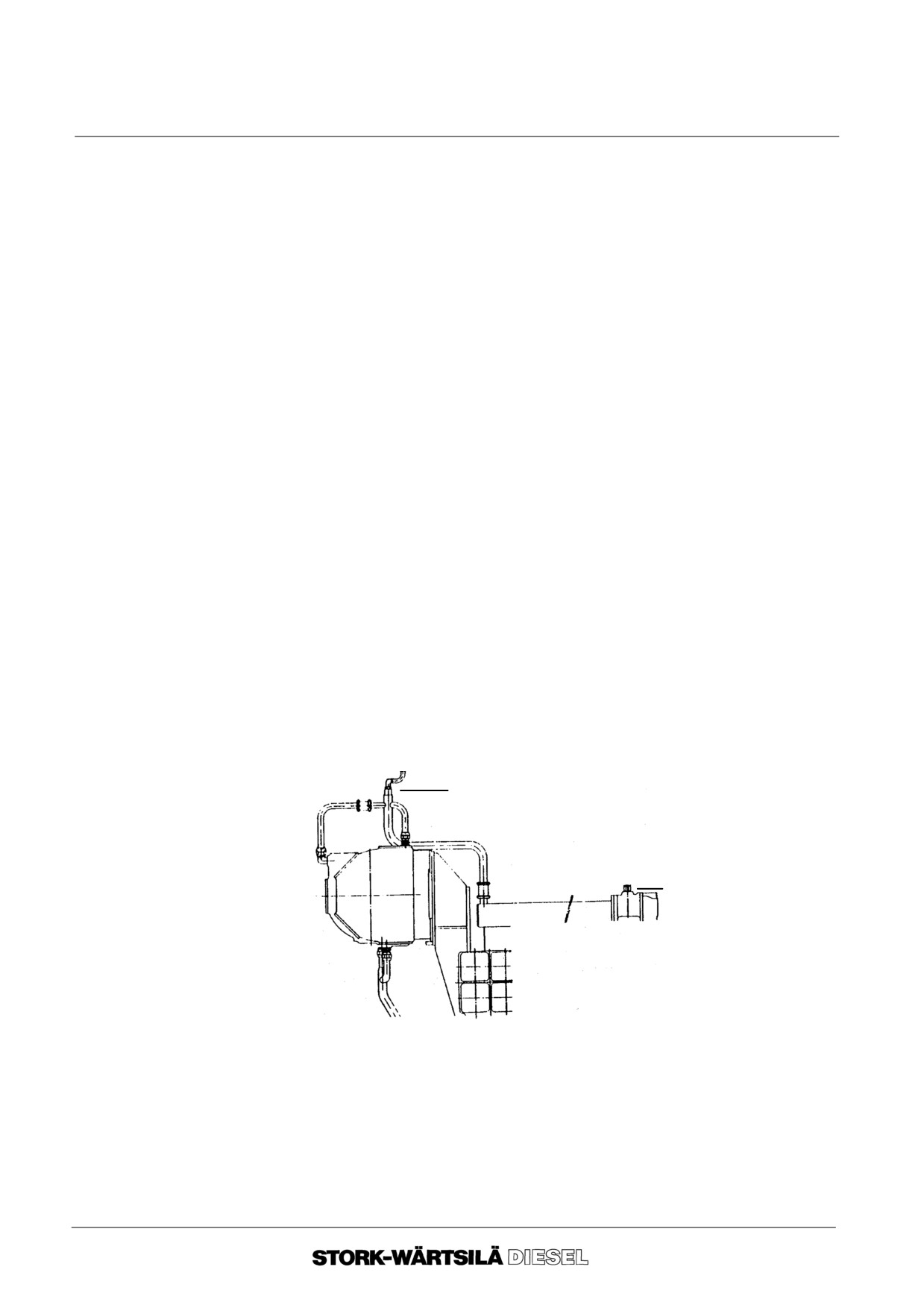
Manual
F 240
COOLING WATER SYSTEM
7C COOLING WATER DE--AERATION
Before starting work, consult:
-- chapter 2, ”BACKGROUND INFORMATION”.
General
Cooling water de--aeration on the engine takes place via the highest points of the cooling
water system. Orifices are provided in the de--aeration connections.
These orifices must be checked periodically.
Checking and
1. Drain the cooling water expansion tank.
inspection
2. Clean the expansion tank internally.
3. Loosen the connections of the de--aeration lines on the de--aeration points.
4. Check whether the orifices are open (diameter orifice openings 3 mm.).
5. Check whether the lines to and from the expansion tank are not clogged.
6. Connect the de--aeration lines correctly to the de--aeration points.
Attention!
In case the cooling water system is equipped with an automatic de--aeration de-
vice, it must be removed, cleaned, and checked on good working and then re--
fitted.
7. Refill the cooling water expansion tank to the required level.
Orifice
Orifice
--o--o--o--o--o--
Ver. 01
7 -- 6
Manual
F 240
COOLING WATER SYSTEM
7D COOLERS
Before starting work, consult
-- chapter 2, ”BACKGROUND INFORMATION”.
1. The heat
Cleaning and Inspection of lube oil or water cooler:
Exchangers
Cleaning Intervals depend heavily on the operating conditions and the state of the
cooling water. If these are less than optimal, cleaning should be effected at least twice
a year.
See sub--suppliers manuals for internal cleaning and inspection.
2. The air cooler
Cleaning:
Cleaning intervals depend heavily on the operation conditions and the state of the
cooling water and the suction air.
To ensure effective cleaning of the cooler, this job has to be carried out by a specialist
firm. However, if it is unavoidable to clean the cooler on the spot,
proceed as follows :
Water section:
The water section can be cleaned by means of chemicals, or mechanically, by brush-
ing. See sub--suppliers manuals.
Air section:
The air section must be cleaned with an agent capable of dissolving the deposits that
have been built up. See sub--suppliers manuals.
If the air cooler has soft iron sacrificial anodes, these must be examined each time the
cooler is cleaned. In some types of air coolers the air flow must have a specific direc-
tion, indicated on one side of the side plates. When assembling and mounting such
coolers make sure that the air flows in the proper direction.
Insufficient Cooling
Possible causes and remedies :
--
Air in the water section -- open vent plug. If an automatic de--aerator is fitted,
this must be checked for proper functioning.
--
Insufficient water supply -- examine supply lines.
--
Deposits on cooling fins and / or in the water section -- clean cooler.
--o--o--o--o--o--
Ver. 01
7 -- 7
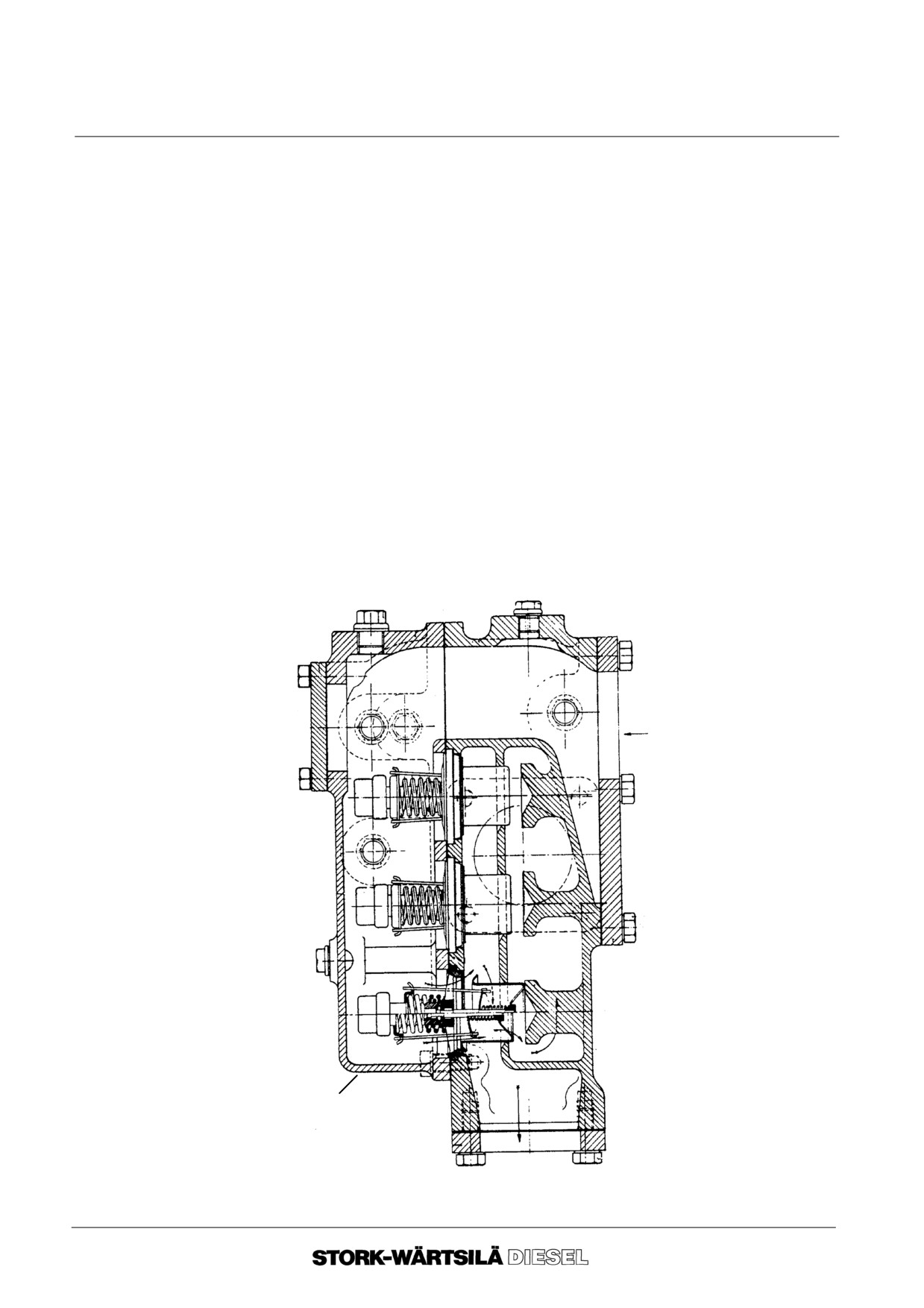
Manual
F 240
COOLING WATER SYSTEM
7E COOLING WATER THERMOSTATS
Before starting work, consult:
-- chapter 2, ”BACKGROUND INFORMATION”.
The thermostatic three--way valve is equipped with three elements. In cold condition, the
thermostatic elements are closed and no water can flow through the heat exchanger.
When the temperature of the water rises, the wax elements expand, and causes the
elements to open against spring pressure, so that the passage to the heat exchanger is
released.
If the water becomes excessively hot or remains too cold, the three thermostatic
elements must be examined.
Inspection of the thermostatic elements:
1. Drain the cooling water by removing the drain plug from the thermostat housing
(proceed carefully when the engine is still hot).
2. Remove the thermostat cover
3. Place the elements in a basin filled with water. Heat the water and with the aid of a
calibrated thermometer check whether the element opens at the correct tempera-
ture. If the element does not open at the correct temperature, it must be renewed.
4. Refit all parts in the reversed order.
Drain plug
Cover
Thermostatic 3--way valve
--o--o--o--o--o--
Ver. 01
7 -- 8
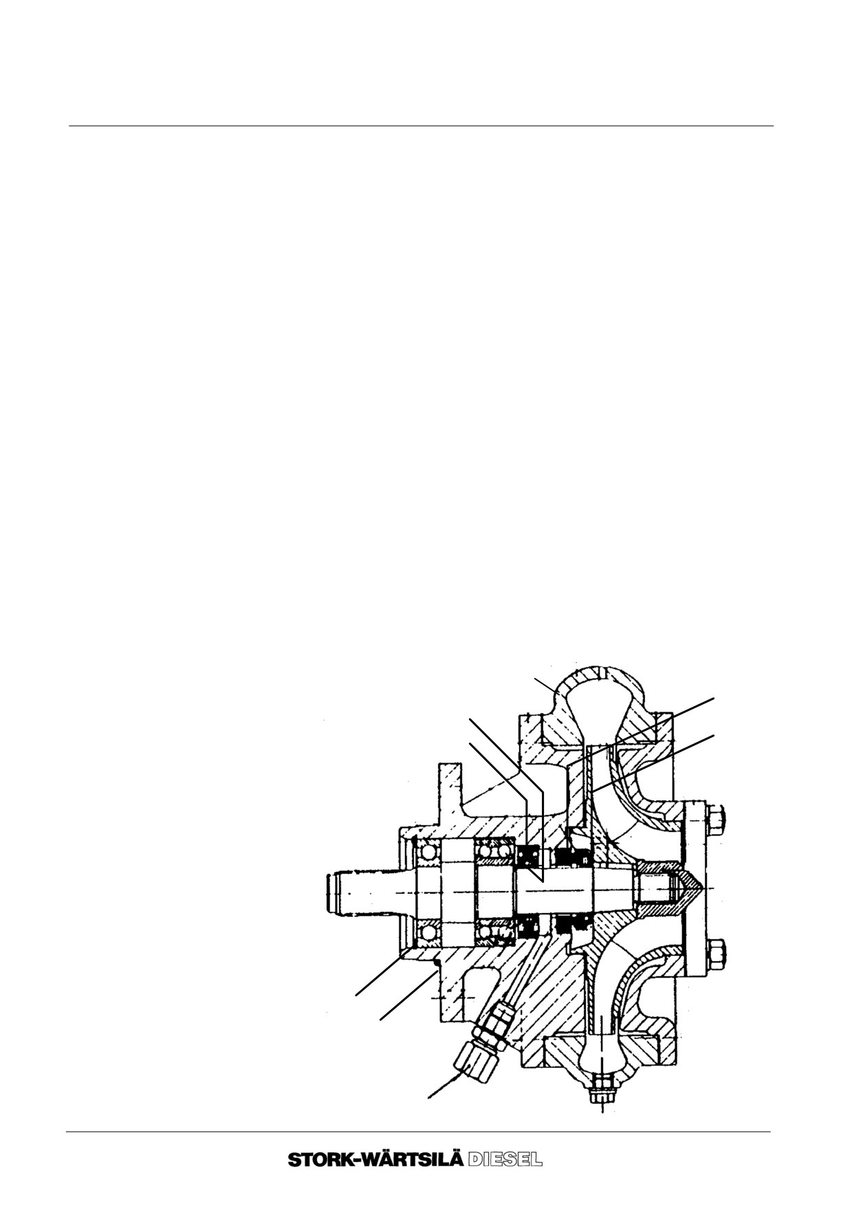
Manual
F 240
COOLING WATER SYSTEM
7F COOLING WATER PUMP
1. Disassembly
If oil and / or water is seen to run out of the leak indicator F, all sealing rings have to
be renewed.
1.
1. Remove the suction and delivery pipe from the pump.
1.
2. Remove the pump casing.
1.
3. Slacken the nut for impeller attachment one full turn.
1.
4. Remove the pump from the gearbox.
1.
5. Remove the inner circlip A.
1.
6. Dislodge the impeller from its cone by tapping the nut with a hammer and
support the backside of the impeller. If the impeller is not coming loose, warm
up the impeller till approx. 120oC.
1.
7. Unscrew the nut completely and withdraw the impeller, (and if applied the
key) the sliding ring seal B and pump shaft with bearings.
1.
8. Withdraw the oil sealing ring C and the ceramic stationary seal ring D from
the pump bracket.
1.
9. If the inner ring E of the pump shaft shows wearing grooves, it must be re-
newed.
Release the inner ring by heating it to approx. 200oC.
Remove all the residual loctite from the pump shaft.
1.
10.Inspect the double--ball angular contact bearing and the single ball bearing.
In most cases they shall have to be renewed.
pump casing
D
E
B
C
A
O--ring
F
Ver. 01
7 -- 9
Manual
F 240
COOLING WATER SYSTEM
7F COOLING WATER PUMP
2. Reassembly
Fitting a new inner ring should be done as follows:
2. 1. Clean and degrease the pump shaft on the location, for the inner ring.
2. 2. Degrease the new inner ring.
2. 3. Lubricate the ball bearings sparingly with bearing grease to prevent Loctite
from adhering to the balls of the bearing.
2. 4. Smear the location for the inner ring with Loctite.
2. 5. Slide the inner ring onto the pump shaft and up to the correct position.
2. 6. Remove all surplus Loctite.
2. 7. Allow the Loctite to harden at least 20 minutes before fitting the shaft.
After fitting the new inner ring, reassemble and fit the cooling water pump as follows:
2.
8. Clean and inspect all parts of the cooling water pump thoroughly and check if
the leak indicator hole (F) is open.
2.
9. Rub the pump shaft splines with Molykote. Just smearing the splines is
not enough.
2.
10.Fit the oil sealing ring (two--side seal) in the cooling water pump bracket.
2.
11. Fill the space formed by the V of the oil sealing ring with grease.
2.
12.Fit the ceramic stationary seal ring carefully in the pump bracket.
2.
13.Fit the bearings on the pump shaft and position the shaft in the pump bracket
and fit the inner circlip.
2.
14.Check that the pump shaft runs lightly.
2.
15.Position the sliding ring seal.
2.
16.Degrease the cone of the pump shaft with a solvent agent. Do the same with
the conical inside part of the impeller and the nut.
2.
17.Warm up the impeller till 100oC.
2.
18.Sparingly apply loctite to the shaft cone and the nut thread.
2.
19.Fit the impeller in a turning movement, fit immediately the impeller nut to the
correct torque (50 Nm.).
2.
20.Remove all surplus loctite.
2.
21.Fit the pumping casing with gasket to the pump bracket.
2.
22.Place the O--ring onto the pump bracket.
2.
23.Fit the pump to the gearbox.
2.
24.Reconnect the suction pipe and the delivery pipe.
Note :
When the engine has been started a slight cooling water leakage may be observed,
but this should stop after approx. 1 hour. Such leakage is due to the fact that the sliding
ring seal may require time to wear in on the ceramic stationary seal ring.
--o--o--o--o--o--
Ver. 01
7 -- 10
Manual
F 240
COOLING WATER SYSTEM
7G INSPECTION COOLING WATER SPACE
This consists of a general visual examination of the cylinder block cooling water space.
Attention should be paid to the following :
--
Serious corrosion ;
--
Signs of cavitation ;
--
Sludge formation ;
--
Line deposits and other undesirable phenomena ;
--
Gas leakage
Gas leakage is noticeable to:
--
Altering cooling water pressure ;
--
Higher cooling water temperatures ;
--
Gas bells in cooling water expansion tank ;
--
Deteriorating cooling water quality.
--o--o--o--o--o--
Ver. 01
7 -- 11
Manual
F 240
COOLING WATER SYSTEM
7H GENERAL DIAGRAM
Explanation of the item numbers in the diagram.
1. HT--circuit
No.
Name
1. 0
Cooling water pump ;
1.
1.
Cooling water inlet channel ;
1.
2.
Cooling water outlet manifold ;
1.
3.
De--aeration points (orifice 3 mm) ;
1.
4.
Thermostatic three--way valve ;
1.
5.
Water cooler ;
1.
6.
Butterfly valve
1.
7.
Cooling water tank.
2. LT--circuit
No.
Name
2. 0
Cooling water pump ;
2.
1.
Blind flange for emergency operation
2.
2.
Adjustable orifice ;
2.
3.
Air cooler ;
2. 4
Lubrication oil cooler.
3. Turbocharger
No.
Name
3.1
Turbocharger.
4. Miscellaneous
No.
Name
4.
1.
Butterfly valve.
Explanation
B
L.T. Cooling water supply ;
letters
C
L.T. Cooling water return ;
D
Connection emergency cooling L.T. circuit (supply) ;
E
Connection emergency cooling H.T. circuit (supply) ;
F
Connection emergency cooling H.T. circuit (return) ;
PI
Pressure indicator ;
TAH
Temperature Alarm High ;
TI
Temperature indicator
LI
Level indicator
LS
Level switch
Ver. 01
7 -- 12
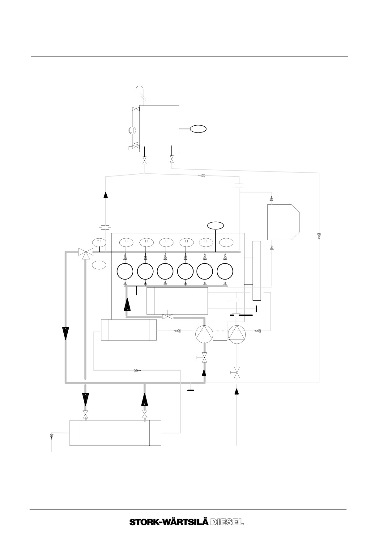
Manual
F 240
COOLING WATER SYSTEM
7H GENERAL DIAGRAM
LS
1.7
1.3
1.3
PI
3.1
1.4
1.2
TAH
1.1
E
2.3
2.2
D
2.1
2.4
2.0
1.0
1.6
4.1
F
1.5
B
C
--o--o--o--o--o--
Ver. 01
7 -- 13
Manual
F 240
COOLING WATER SYSTEM
7H GENERAL DIAGRAM
Ver. 01
7 -- 14
Manual
F 240
AIR INLET AND EXHAUST SYSTEM
8A INTRODUCTION
5. General
In order to optimize the engine’s performance, it is necessary to compress and to
regulate the temperature of the combustion air.
This is carried out by the use of a turbocharger and an air cooler
6.
Description of
This paragraph is a general description of the function of engine parts in the air inlet
engine parts
and exhaust system.
The main parts of the air inlet and exhaust system are shown in the general diagram
(paragraph 8F). These main parts have a number which corresponds to the number
in the diagram. This number is placed between brackets in the description below.
Inlet air filter
The supply of inlet air can be done:
(1.1)
-- Via the air filter of the turbocharger. In this case large volumes of air need to be
delivered close to the turbocharger intake (approx. 2 times the combustion air
usage).
-- Via an air intake air pipe tube from outside with a separately installed air filter.
Fresh air that contains too much dust and/or chemical pollution must be filtered
by a separately installed filter.
When the air filter becomes contaminated the resistance of the air filter increases.
If the air filter is defective or the filtering of the air is insufficient a reduction of the life
of engine components can be the result.
Turbocharger
The turbocharger consists of a turbine and a compressor on one shaft. Energy from
(1.2)
the exhaust gases drives the turbine. The exhaust gasses expand (reducing the
temperature).
The compressor, driven by the turbine, compresses the inlet air (increasing the
temperature).
See the SUB--SUPPLIERS MANUAL for a detailed description of the turbocharger.
Ver. 01
8 -- 1
//////////////////////////////////////////