Dresser-Rand. Instruction Manual for Single Stage 350, 500, and 700 Frame Steam Turbines (2011) - page 3
SST Turbine Instruction Manual
Low Voltage Electrical Components
h. Complete installing flange bolts using the sequence in Figure L-3 and the
applied torques in Table L-2.
i.
After the turbine is completely re-assembled and the coupling is made up, it
should be brought up to operating temperature and the bolts checked again.
There should be no slacking off of the bolts as a result of heating and cooling.
j.
When removing or replacing the top half of the casing, great care must be
exercised to avoid damage.
L.4
Carbon Ring Removal and Replacement
L.4.1
Carbon Ring Removal
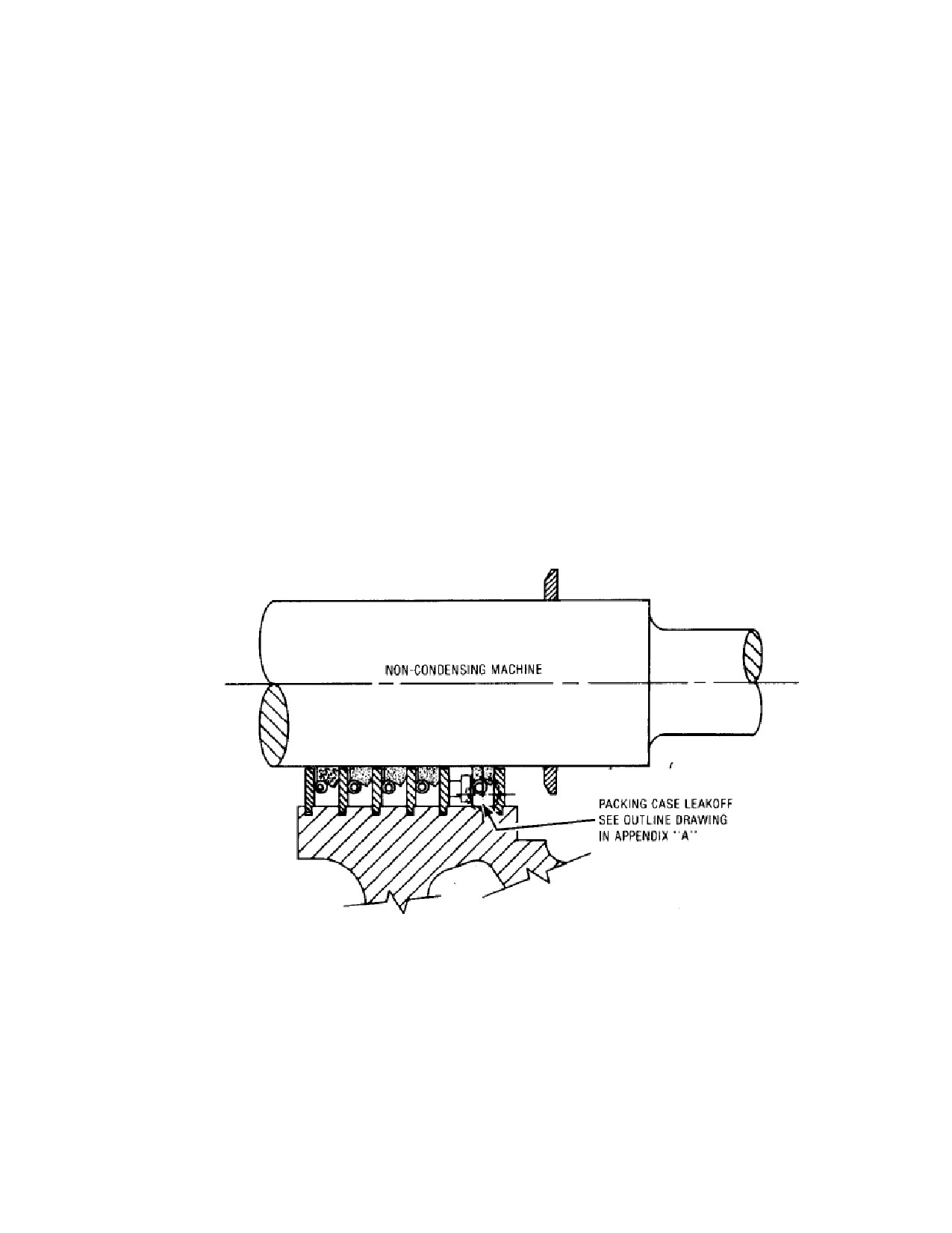
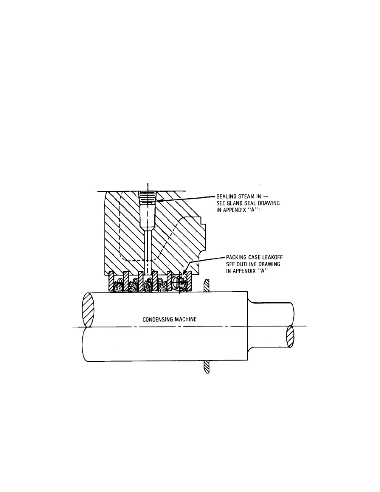
Refer to the following figures:
L-4
Carbon Ring Assembly, Non-Condensing Turbine
L-5
Carbon Ring Assembly, Condensing Turbine
Figure L-4 Carbon Ring Assembly, Non-Condensing Turbine
When removing the packing rings, be sure to keep each ring by itself. Note that the
ring segments are marked; these marks should be placed together when fitting or
replacing the rings in the turbine. When gland leakage indicates the necessity of
packing ring maintenance, it is recommended that new rings be installed.
SST Turbine Instruction Manual
Revision A
203
Low Voltage Electrical Components
SST Turbine Instruction Manual
New packing rings furnished by Dresser-Rand will be made with the correct
diametral clearance, based on the original contract steam conditions. A packing
ring diagram, EW-33275 located in Appendix A, shows the part number and
location of each ring in the turbine.
When it is necessary to refit old rings (due to emergency condition) remove a small
amount, approximately
0.001”/0.025 mm from the ends of each segment,
maintaining flat square ends. The diametral clearance between the carbon rings
and the shaft should be as specified in the Packing Ring Diagram.
When installing new rings, the shaft surface should be smooth and highly polished,
clean and free of dust, water or oil. The spacer rings should be clean and smooth
with a true surface. If the sealing surface of the spacer ring is warped, the carbon
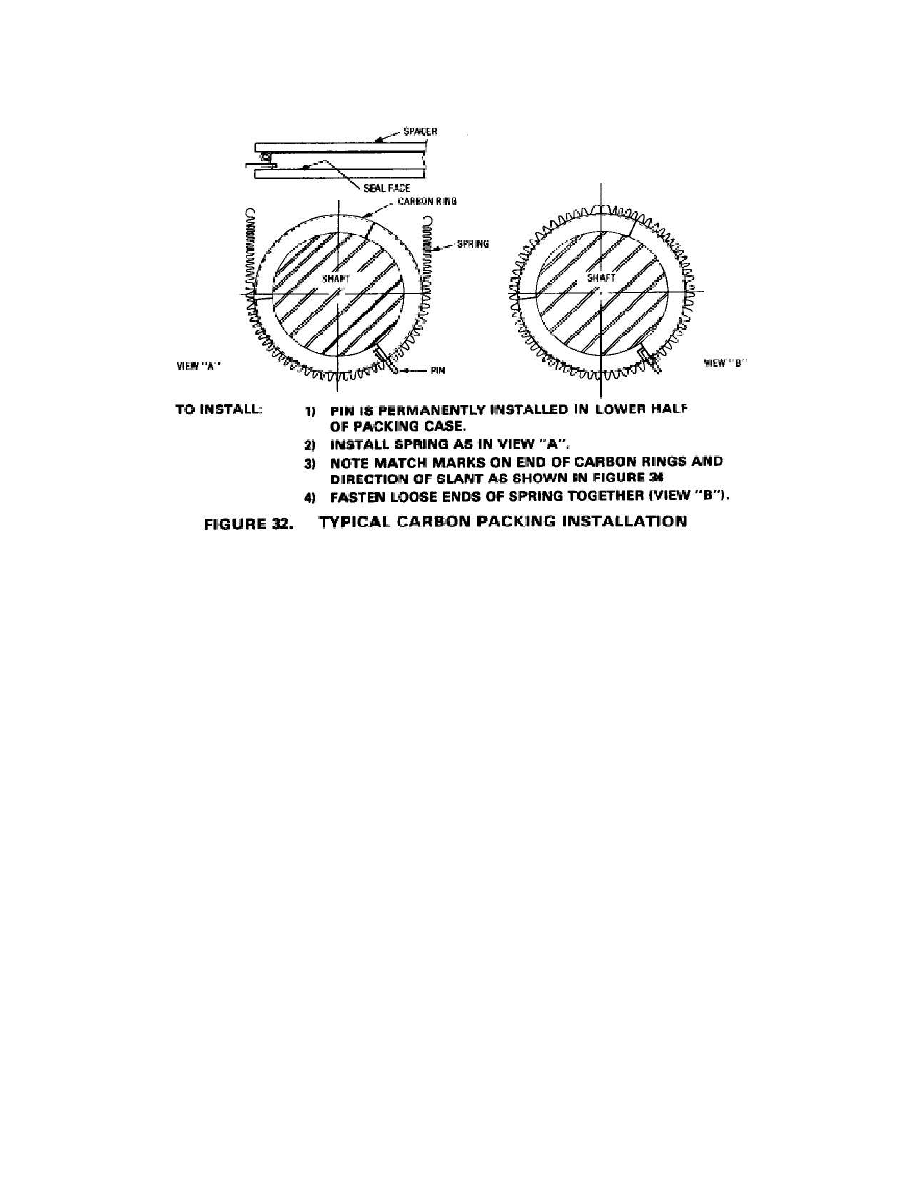
ring cannot seal. Warped spacer rings should be replaces. To install new carbon
rings, see Figure L-6 for procedure.
Figure L-5 Carbon Ring Assembly, Condensing Turbine
a. If there is a leak-off connected to the cover disconnect this and remove the
pipe from the cover.
204
Revision A SST
Turbine
Instruction
SST Turbine Instruction Manual
Low Voltage Electrical Components
b. Remove turbine cover according to the procedure specified in Section L.3.1.
c. Disconnect the garter spring ends. Remove the garter springs and carbon ring
segments. Note that the anti-rotation pin in the packing case may interfere
with carbon ring segment removal. If so, simply rotate the segment in the
opposite direction, or rotate the partition plate.
d. Inspect and clean the spacer rings. If the spacer rings are damaged they should
be replaced. The shaft will have to be removed. Refer to Section L.9 Rotor
and Turbine Wheel Removal and Replacement.
e. Clean the stainless steel high velocity oxy fuel-coated surfaces of the shaft
with stainless steel high velocity oxy fuel spray. Inspect the stainless steel
plating. If plating is bubbled, split or peeling the shaft must be replaced.
L.4.2 Carbon Ring Replacement
a. Thread the garter springs into the slots between the spacer rings.
b. Install the carbon ring set one complete set at a time. Be certain to maintain
the correct relationship between carbon ring segments by matching dots
stamped on each segment. Dots should face toward the wheel. The anti-
rotation notch must engage the anti rotation pin.
c. Connect the garter springs to retain the carbon rings.
d. Replace the turbine cover per Section L.3.1.
SST Turbine Instruction Manual
Revision A
205
Low Voltage Electrical Components
SST Turbine Instruction Manual
Figure L-6. Typical Carbon Packing Installation
L.5
Casing Labyrinth Seal Removal and Replacement
No field repairs of labyrinth are recommended. Slight deposits of the labyrinth on
the turbine shaft is an acceptable condition.
When installing new labyrinth rings, polish the shaft clean to remove any deposits
which may have formed.
Make sure that the quadrants of each ring are matched and that the rings are
installed in their proper position as identified in the packing ring diagram, EW-
33275. On installation of each quadrant of a gland-packing ring, make sure a
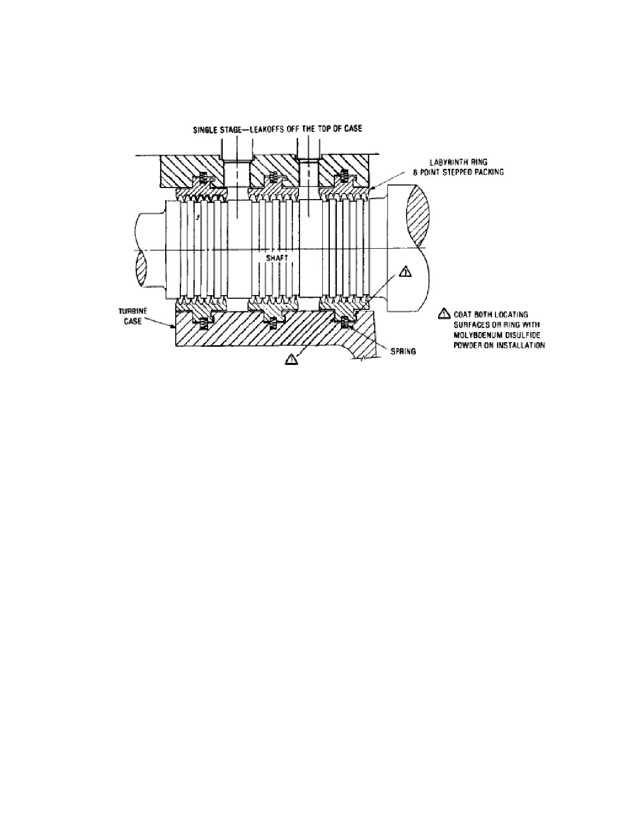
compression ring is installed in each hole. (See Figure L-7)
All SST turbine designs require removal of the turbine cover to remove, inspect,
and replace labyrinth seals. Refer to the appropriate section below to service these
labyrinth seals.
L.5.1
Casing Labyrinth Seal Removal
206
Revision A SST
Turbine
Instruction
SST Turbine Instruction Manual
Low Voltage Electrical Components
Refer to the following figure:
L-7 Labyrinth Seal Assembly
a. Remove the turbine cover according to the procedure specified in Section
L.3.1. The labyrinth seal segment(s) in the cover will be removed during this
operation.
b. Remove leak-off piping before removal of seals.
c. Inspect labyrinth seal segments, locating springs, and the shaft for corrosion,
scoring, or other damage. Clean all components. Replace any part that is no
longer serviceable. Labyrinth seal segments must be replaced as a set. Severe
rubbing one side of all labyrinth teeth may indicate a worn or failed thrust
bearing. Refer to Section L.6.2, Thrust Bearing Removal and Replacement, if
the thrust bearing is suspect.
L.5.1
Casing Labyrinth Seal Replacement
a. Install labyrinth seal segments into the lower half casing by rotating them
between the shaft and casing. Install the locating springs in the depressions, in
the segment and compress the springs as the segment is rotated.
SST Turbine Instruction Manual
Revision A
207
Low Voltage Electrical Components
SST Turbine Instruction Manual
b. Install the labyrinth seal segments into the seal housing lower half with
springs. Note that the labyrinth seal segments are matched-marked. Insure
that they are installed with their match-marks next to each other.
c. Install the labyrinth seal segments and springs in the seal housing upper half.
d. Replace the turbine cover and gland-housing cap according to the procedure
specified in Section L.3.1.
L.6
Turbine Bearing Removal and Replacement
SST turbines can be supplied with two, split sleeve journal bearings and one ball
thrust bearing. Shaft journal and bearing dimensions are shown on the turbine data
sheets. When running clearance is excessive, the bearings should be replaced not
re-babbitted. Approximately 0.004”/0.101mm over the maximum clearance is
considered excessive. However, if conditions permit and the unit runs smoothly,
bearings may be kept in service when clearances exceed the recommended
maximum clearance. It is left up to the discretion of the operating engineer as to
when bearing replacement is necessary. The bearings are longitudinally split to
permit removal and installation without removing the shaft.
Refer to the following figures:
M-4
Bearing Housing Assembly, Exhaust End Simple Bearing Case
M-5
Bearing Housing Assembly, Exhaust End Hi Cap Bearing Case
M-6
Bearing Housing Assembly, Non-Drive End Simple Bearing Case
M-7
Bearing Housing Assembly, Non-Drive End Hi Cap Bearing Case
L.6.1
Sleeve - Type Journal Bearing Removal and Replacement
The journal bearing can be inspected and replaced without removing the turbine
upper case.
Sleeve Bearing Removal
a. Remove the bolts securing the governor mounting housing to the steam end
bearing cap.
b. Use a soft drift and hammer to loosen the upper half of the bearing housing.
Tap on the area where the upper half overlaps the lower half. Remove the
upper half.
c. Lift, raise, and slide oil rings over to allow removal of the upper bearing half.
208
Revision A SST
Turbine
Instruction
SST Turbine Instruction Manual
Low Voltage Electrical Components
d. Raise the shaft slightly (0.040 inch/1 mm) to expose the bearing split line and
remove the upper bearing half.
e. Rotate lower bearing half out of the bearing housing with the locating tab
exiting the housing upon initial rotation.
f.
The shaft can then be rested on the labyrinth seal or optional Inpro/Seal after
the bearing is removed.
g. Inspect bearings for wear or scoring. Replace if necessary. Refer to Section
B.9 for recommended sealant.
h. Inspect shaft journals. If journals are worn or scored, the shaft must be
replaced. Slight scratches or nicks can be removed by stoning or with crocus
cloth.
Sleeve Bearing Replacement
a.
Verify that the bearing journal is clean and undamaged. Coat the journal with
turbine oil.
b.
Lift the shaft (0.040 inch/1 mm) to permit sufficient room to rotate the lower
bearing half into the housing.
c.
Rotate lower bearing half into bearing housing with the locating tab correctly
aligned with the slot in the housing. Note that the bearing split line is below
the bearing housing split line. On installation, the bearing stops will act as
dowels and properly locate the bearings.
d.
Lower the shaft onto the lower bearing half.
e.
Snap the upper half of the bearing into the upper bearing housing half, aligning
the tab so that it fits into the milled slot. After installation, check clearance
using plasti-gage or lead wire.
f.
Place the oil ring(s) into slot(s) on the upper bearing half and verify that they
are free to turn.
g.
Drain and clean bearing housing reservoirs and refill to the proper level with
clean oil.
h.
Apply a thin coating of sealant to the horizontal joint of the bearing housings.
Refer to Section B.9 for recommended sealant.
i.
Replace the bearing cap carefully, so as not to crush the sleeve bearing tabs.
SST Turbine Instruction Manual
Revision A
209
Low Voltage Electrical Components
SST Turbine Instruction Manual
j.
Insert and drive in the dowel/taper pin.
k. Install washer and nuts on studs. Torque the nuts first to 25 ft-lbs (34 N-m)
and then to 55-65 ft-lbs (75-88 N-m).
l.
Install bolts and torque them to 55-65 ft-lbs (75-88 N-m).
m. Rotate shaft by hand and observe oil rings through inspection holes in the
bearing cap to verify that rings rotate freely.
n. Install bolts holding upper bearing housing half to governor mounting housing.
L.6.2
Thrust Bearing Removal and Replacement
The standard thrust bearing is a ball bearing located in the non-drive end bearing
housing. Tilting pad thrust bearings are supplied optionally on some turbines.
Refer to the appropriate vendor manual for details.
For turbines where the governor is coupled to the shaft, remove steam end bearing
case cap and then uncouple and remove the governor. For gear driven Woodward
governors disconnect the governor linkage without disturbing the length of the
connecting rod, then remove the bolts that fasten the governor to the housing and
lift off the governor.
The thrust bearing is properly positioned on the turbine shaft by shims at the
factory and should require no adjustment. These shims are used to adjust the
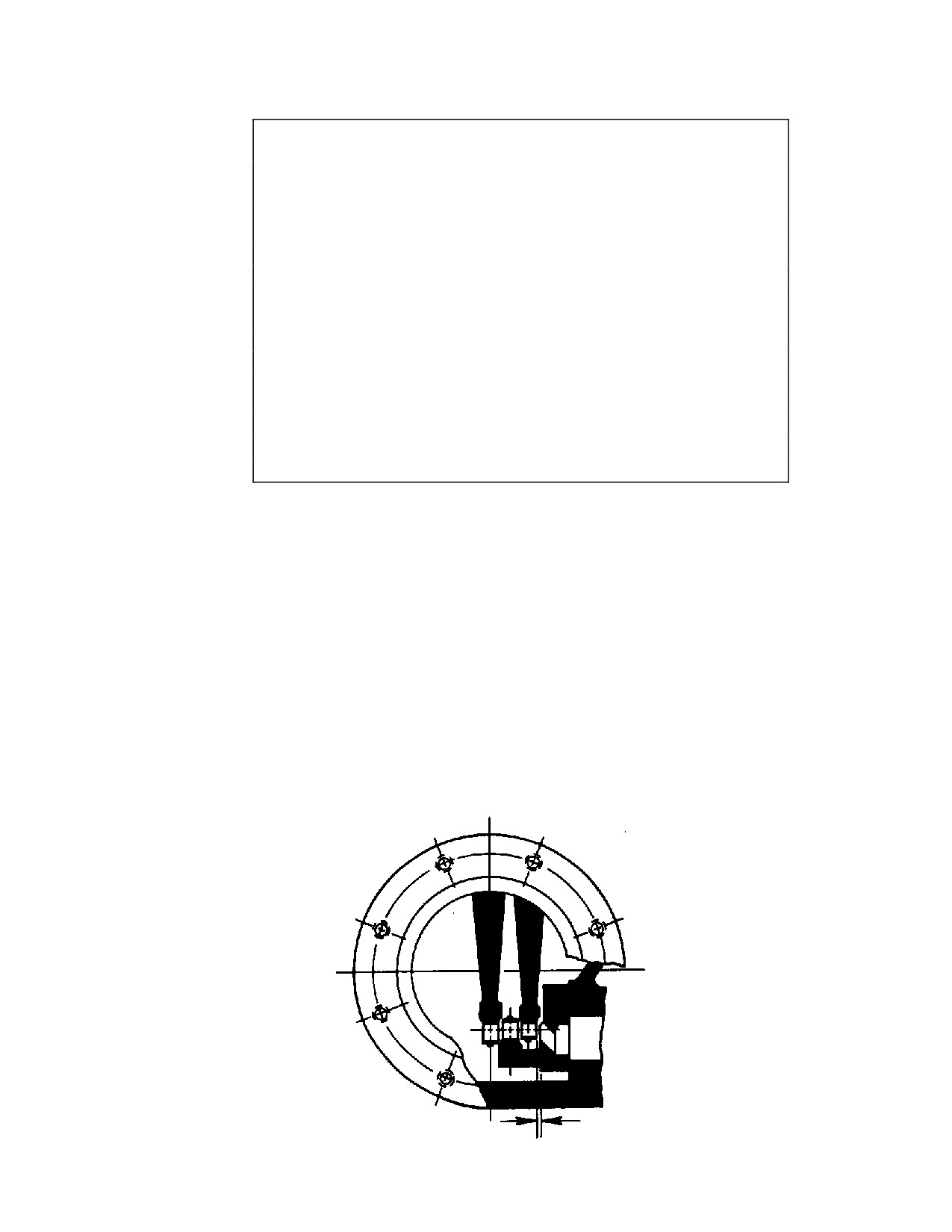
nozzle ring-to-wheel clearance. See figure L-8. Shims are also used to set the
running clearance (float) on a shoe or collar type thrust bearing. Recommended
running clearance for the thrust bearing is 0.010” to 0.020”.
Thrust Bearing Removal
a. Remove the turbine rotor according to the procedure specified in Section L.9.
b. Remove lock nut and lock-washer from the turbine shaft.
c. On turbines with ball bearing journal bearings, remove the oil ring and oil
ring sleeve.
d. Using a suitable puller, remove the thrust bearing from the shaft. Tag both
sets of upper and lower shims to facilitate re-assembly.
e. Using a suitable puller, remove the journal ball bearings from the
shaft.
210
Revision A SST
Turbine
Instruction
SST Turbine Instruction Manual
Low Voltage Electrical Components
CAUTION
When removing or replacing ball bearings mounted on a shaft,
NEVER PRESS OR APPLY FORCE to the OUTER RACE, as
this may damage the races or balls. NEVER HAMMER on
either the inner or outer races. Bearings should be pressed on
or off shafts with a steady force. Always inspect the shaft for
burrs or foreign material and remove them as necessary, prior
to removal or installation of bearings. If a BEARING BINDS
during installation or removal, DETERMINE THE CAUSE and
CORRECT it rather than apply more force. Installation should
be performed by heating bearings prior to assembly. Heat
bearings slowly and evenly to a temperature not exceeding
250F (120C). Special electrical heaters are available from
industrial suppliers for bearing heating. Alternatively, bearings
may be heated in an oil bath.
f.
On turbines with sleeve journal bearings, take care not to lose the flat spring
located in the bottom of the bearing housing groove. This spring prevents
rotation of the outer race of the thrust bearing.
Thrust Bearing Replacement
a. Install thrust bearing on the shaft with the shield (if so equipped) facing out.
Make sure that the bearing is installed with the manufacturer’s marking, such as a
bearing number or “thrust here”, facing upstream (towards the steam end of the
shaft). Before installing the bearing case cap, check thrust bearing adjustments for
the proper thickness of shims: 0.050”, 1.27mm minimum with assembled shaft
moved fully towards steam end. Set the clearance by properly positioning the
thrust bearing. See Figure L-8 below:
Figure L-8 Nozzle Ring-To-Wheel Clearance
SST Turbine Instruction Manual
Revision A
211
Low Voltage Electrical Components
SST Turbine Instruction Manual
b.
On turbines with ball bearing journal bearings, replace the oil ring sleeve and
the oil ring.
c.
Replace lock-washer and lock nut.
d.
Bend the lock tab(s) to lock the nut into position.
e.
Replace the turbine rotor into the turbine casing according to the procedure
specified in Section L.9.
f.
To replace a ball-type thrust bearing, see steam end bearing case assembly and
longitudinal section drawings in Appendix A and proceed as follows:
g.
Remove governor.
h.
Remove steam end bearing case cap.
i.
Remove bearing case end cover.
j.
Disassemble parts from steam end of turbine shaft as necessary to gain access
to the thrust bearing; then remove the bearing. Tag both sets of upper and
lower shims to facilitate reassembly.
k.
Reassemble by reversing the removal procedure. Make sure that the bearing is
installed with the manufacturer’s marking, such as bearing number or “thrust
here”, facing upstream (towards the steam end of the shaft). Before installing
the bearing case cap, check the thrust bearing adjustments for the proper
thickness of shims.
L.6.3
Ball-Type Journal Bearing Removal and Replacement
Bearing removal and replacement on SST 500 and SST 700 turbines with ball
bearing journal bearings is accomplished using the same procedure as that specified
for the thrust bearing in section L.6.2, Thrust Bearing Removal and Replacement.
The only exception is that there is no lock washer or nut retaining the bearing on
the drive end of the shaft. Removal of the exhaust end bearing requires the
removal of the coupling and outboard bearing housing seal. Refer to Section L.5,
Casing Labyrinth Seal Removal and Replacement.
L.7
Bearing Housing Shaft Seal Removal and Replacement
Bearing housings are provided with either labyrinth-type oil seals or optional inpro
seals or magnetic seals. These seals prevent oil leakage from bearing housings and
also prevent penetration of steam, dust, and dirt into the housings.
212
Revision A SST
Turbine
Instruction
SST Turbine Instruction Manual
Low Voltage Electrical Components
Bearing housing shaft seals are mounted on the turbine shaft. There are two seals
on the drive end bearing housing and one on the non-drive end bearing housing.
Inpro seals & magnetic seals are optional, non-contacting bearing housing oil seals
that replace the three standard labyrinth-type bearing housing seals. The drive end
bearing housing has both an inboard and outboard seal. The non-drive end has only
an inboard seal.
Inpro or Magnetic Seal Removal (Steam End)
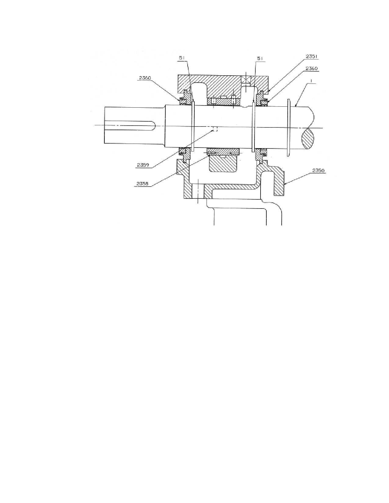
Refer to the following figure:
L-9
Bearing Housings With Optional Inpro/Seals
a. Remove the half-coupling from the shaft.
b. Remove the rotor from the turbine according to the procedure specified in
Section L.9.
c. On sleeve bearing turbines, remove the thrust bearing from the shaft according
to the procedure specified in Section L.6.2
d. Clean the turbine shaft outboard of the seal.
e. Slide the seal assembly off the turbine shaft.
Inpro or Magnetic Seal Replacement (Steam End)
a. Clean the shaft and remove any burrs that could damage the seal O-ring.
b. Lubricate the shaft and seal O-ring with turbine oil to facilitate seal insertion
on the shaft.
c. Slide the seal assembly onto the shaft, placing it at is approximate final
position.
d. On sleeve bearing turbines, replace the thrust bearing according to the
procedure specified in Section L.6.2
e. Replace the rotor according to the procedure specified in Section L.9, using
care to correctly position the seal when installing upper halves of the bearing
housings.
SST Turbine Instruction Manual
Revision A
213
Low Voltage Electrical Components
SST Turbine Instruction Manual
f.
Replace half-coupling on the shaft.
Inpro or Magnetic Seal Removal (Exhaust End)
(Note: Rotor must be out of the turbine.)
a. Remove the half-coupling from the turbine shaft.
b. Remove journal bearing, oil slingers, and any other items located outboard of
the innermost seal.
c. Slide the seal out of the recess in the bearing housing and off the shaft.
Inpro or Magnetic Seal Replacement (Exhaust End)
a. Clean drive end of the shaft and remove any burrs that could damage the seal
O-ring.
b. Lubricate the shaft and seal O-ring with turbine oil to facilitate seal insertion
on the shaft.
c. Slide the seal onto the shaft, placing it into the recess in the lower bearing
housing half.
d. Replace the upper bearing housing half according to the procedure specified in
Section L.6.
e. Replace half-coupling on the shaft.
f.
Reassemble rotor into the turbine along with the steam seals.
214
Revision A SST
Turbine
Instruction
SST Turbine Instruction Manual
Low Voltage Electrical Components
Figure L-9. Bearing Housings with Inpro/Seals
L.8
Bearing Housing Removal and Replacement
SST bearing housings are attached to the lower turbine casing with bolts. Two
dowel pins on each housing, maintain their position. Alignment of bearing
housings to the casing and to each other is essential for vibration-free operation and
long bearing life. Bearing housings are accurately aligned at the factory prior to
pinning. Should it be necessary to remove or replace a bearing housing, it is
essential that the alignment be checked and corrected, if necessary, prior to re-
installation of the rotor.
Bearing housing alignment is a precision process that requires skill, experience,
and precise measurement. If there is any question regarding the ability of site
personnel to properly align bearing housings, Dresser-Rand recommends that a
factory-trained serviceman be engaged to perform the service. Contact your
Dresser-Rand manufacturer’s representative or the Dresser-Rand factory to
schedule a service visit.
L.9
Turbine Rotor & Turbine Wheel Removal and Replacement
Refer to the following figures:
SST Turbine Instruction Manual
Revision A
215
Low Voltage Electrical Components
SST Turbine Instruction Manual
M-0
SST Turbine, General View
M-1
Trip Throttle Valve Assembly
M-2
Governor, Mounting Housing, and Trip Components
M-3
Gland Sealing Elements
M-4
Hi-Cap Bearing Case Assembly, Exhaust End
M-5
Bearing Housing Assembly, Exhaust End
M-6
Bearing Housing Assembly, Steam End
M-7
Bearing Housing Assembly, Steam End
M-8
Case, Rotor and Mechanical Gland Seals
M-9
Case, Rotor and Carbon Ring Gland Seals
L.9.1
Turbine Rotor Removal & Replacement
The governor, turbine cover, casing labyrinth seals (if so equipped), and carbon
rings must be removed or disassembled to remove the rotor.
Turbine Rotor Removal
a. For turbines where the governor is coupled to the shaft, remove the steam end
bearing case cap; then uncouple and remove the governor.
(See longitudinal
section, Appendix A). For a gear driven Woodward governor, disconnect the
governor linkage without disturbing the length of connecting rod, remove bolts
that fasten the governor to the housing and lift off the governor.
b. Remove the over-speed trip collar according to the procedure specified in
Section L.14.
c. Remove upper halves of bearing housings according to the procedure specified
in Section L.6.1.
d. Remove the top half of the turbine case according to the procedure specified in
Section L.3.
e. Remove shaft packing according to Section L.5.
f.
Remove cap from the exhaust end bearing case and steam end bearing case (if
not already removed in step 1.
g. Remove both main bearing top halves.
216
Revision A SST
Turbine
Instruction
SST Turbine Instruction Manual
Low Voltage Electrical Components
h. Arrange a suitable support for the rotor assembly. Verify that turbine wheel
blades and bearing journal surfaces on the shaft will not make contact with any
surrounding object. Verify that the assembly will not roll off the support.
i.
Use slings and a crane or hoist to lift the rotor assembly just out of the lower
half of bearings; then remove lower half of bearings. Use extreme care when
lifting the assembly to avoid damaging the wheel, blades, shaft, or sector.
j.
Place rotor assembly on the support.
Turbine Rotor Replacement
a.
Verify that the interior of the turbine casing is clean and that all foreign objects
have been removed.
b.
Clean or replace journal bearings (if so equipped) and lubricate journal area of
the shaft to prevent scratching or scoring.
c.
If so equipped, place lower journal half into the bearing housing. Position oil
rings so that they fit into openings provided in the bearing housings.
d.
Using slings and a crane or hoist, lower the rotor assembly into the casing. Use
care to avoid damage to the wheel, blades, shaft, or sector.
e.
Check clearance between first wheel and nozzle ring. This clearance is
obtained by properly locating the thrust bearing. See figure L-8 and thrust
bearing adjustment procedure in section L.6.2.
f.
Replace casing labyrinth seals (if so equipped) according to the procedure
specified in Section L.5.
g.
Replace turbine cover and gland housing upper halves
(if so equipped)
according to the procedure specified in Section L.3.1.
h.
Replace the sleeve bearing upper halves (if so equipped) and bearing housing
upper halves according to the procedure specified in Section L.6.
i.
Replace the governor mounting housing
j.
Replace over-speed bolt trip collar according to the procedure specified in
Section L.14.
k.
Replace governor drive coupling governor and associated linkage according to
the procedure specified in Section L.12.
L.9.2
Turbine Wheel Removal and Replacement
SST Turbine Instruction Manual
Revision A
217
Low Voltage Electrical Components
SST Turbine Instruction Manual
This operation is to be referred to Dresser-Rand service facilities.
CAUTION
DO NOT allow the heating FLAME TO IMPINGE on turbine
BLADES, as this could anneal and WEAKEN them.
WARNING
Exercise appropriate CAUTION in handling the HOT WHEEL
during disassembly and assembly.
CAUTION
Be certain to assemble the wheel and shaft with THE
SHORTER BLADES TOWARD the NON-DRIVE END OF THE
SHAFT. Otherwise, the rotor cannot be installed.
L.9.3
Turbine Rotor Balancing
Whenever a wheel or shaft is replaced, the wheel and shaft subassembly should be
dynamically balanced. This procedure must be performed by a Dresser-Rand
repair facility.
L.10
Nozzle Ring Removal and Replacement
Nozzle rings contain one or more nozzles which expand the inlet steam to a lower
pressure, creating the necessary kinetic energy (velocity) at the entrance of the first
wheel blading.
L.10.1 Nozzle Ring Removal
218
Revision A SST
Turbine
Instruction
SST Turbine Instruction Manual
Low Voltage Electrical Components
After the rotor and guide ring have been removed from the lower half turbine
casing—
a. Loosen and remove nozzle ring cap screws. This may, at times present
a problem. Broken screws will have to be extracted or drilled out.
Note: When nozzle ring is secured with inner and outer bolts, no caulking
strip is used.
b. The nozzle ring may now be lifted out of the casing. Mark the ring to
identify its location if reused (upper or lower half).
L.10.2 Nozzle Ring Replacement
Nozzle rings are caulked in at the outer periphery and bolted to the steam ring
nozzle bolting face of the main casing when a single row of bolting is used. When
a double row of bolting is used, there is not a caulking strip.
a. Identify the upper and lower half nozzle ring. If necessary check that the
valve port bridge walls match their seal surfaces using bluing or white lead.
b. Check that the clearance holes in the nozzle ring and tapped holes in the
steam ring face agree.
c. Thoroughly clean the sealing surface at the steam ring face. If the
surface is smooth, the most common sealing compounds are Turbo R or
Turbo 50. If the surface is rough, use Copaltite. If these compounds are
not available, use a key paste or a mixture of graphite and oil. If none of
these compounds is available, call Dresser-Rand Technical Support.
d. Bolt the nozzle ring half in place. The cap screws should be pulled tight
but not over-tightened. If Allen wrenches bend during tightening, the
screws are overstressed and their heads may snap off when the unit comes
up to temperature. Over-tightening of screws must be avoided. Prick-
punch head clearance holes at four positions so that cap screw heads (if
broken off) cannot come out into the steam path.
L.11
Hand-valve Removal and Replacement
Hand-valves are optional items. Depending on steam conditions, required power
and speed, and initial customer requirements, the turbine may incorporate no hand-
valves, one hand-valve, or two hand-valves.
SST Turbine Instruction Manual
Revision A
219
Low Voltage Electrical Components
SST Turbine Instruction Manual
The purpose of hand-valves is to isolate a nozzle or group of nozzles from inlet
steam, thereby allowing the turbine to operate at reduced power output without
excessive throttling. When operated at reduced power in this fashion, the turbine is
more efficient than it would be if all nozzles were active.
Hand-valves should be either fully open or fully closed, never in between.
Operating with a partially closed hand-valve is not only inefficient, but could result
in steam cutting of the seat resulting in excessive leakage. When putting the unit
into operation, do not close a hand-valve tightly until the turbine is up to operating
temperature and all parts are evenly heated. The reason for this is that the material
of the valve stem is subject to greater thermal expansion than the turbine casing,
and if the valve is closed tightly when cold, it may lock the valve in the closed
position making it difficult to open.
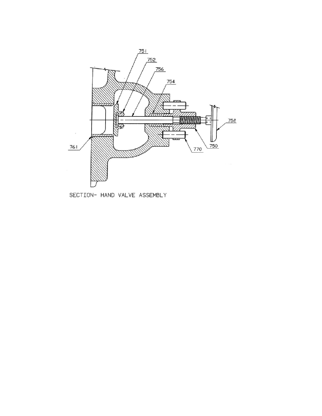
Refer to Figure L-10, Hand-valve Assembly.
L.11.1
Hand-valve Removal
WARNING
Close and tag inlet and exhaust isolating valves and open
drains to depressurize the turbine casing and steam chest
before maintaining hand-valves.
Note: Removal of the hand-valve is done from inside the turbine case.
a. Remove the turbine casing cover and bearing case covers, uncouple the turbine
rotor, and remove the carbon rings. See instructions in other sections of this
manual for these steps.
b. Remove the turbine rotor. Remove the nozzle ring.
c. Once the nozzle ring is removed you can see the hand-valve seat (761). Pull out
the hand-valve seat. The fit is on-line to 0.004” loose.
d. Remove the hand wheel (758). Remove the hand-valve bonnet (750).
e. Push the stem and disc assembly out towards the inside of the turbine. Remove
the old hand-valve packing (754). Note: Count the rings removed.
f. Clean the seat area, nozzle ring face, and all areas that might have sealant.
L.11.2
Hand-valve Replacement
a. Inspect the stem and disc assembly. Hand-valve collar (752) should be tight
and staked to the disc (751).
b. Insert the new stem and disc assembly into the turbine hand-valve location.
220
Revision A SST
Turbine
Instruction
SST Turbine Instruction Manual
Low Voltage Electrical Components
c. Make sure the seat (761) and the bore of the turbine case are clean. Insert the
seat into the hole where it was removed. If there is a slight interference, cool
down the seat in a freezer or with liquid Nitrogen.
d. Install the nozzle ring in accordance with instructions in other sections of this
manual.
e. Assemble new packing (754). Put in the same number of packing rings as
were removed.
f.
Assemble bonnet (750) and hand wheel (758). Tighten the bonnet to compress
the packing until you feel a slight drag on the stem when you screw it in and
out.
L.11.3
Reassembly of the Turbine Rotor and Upper Half Casing
a. Clean all surface areas (turbine casing split-line, bearing case split-lines, etc).
b. Assemble the carbon rings, turbine cover, and bearing case covers per
instructions given in other sections of this manual.
L11.4
Handvalve Adjustment
a. One steam is admitted into the unit, re-tighten the hand-valve bonnet so there
is no steam leaking out of the steam area. This might have to be done again
when there is full pressure inside the casing to prevent leakage at the high
internal pressure.
b. The valve stem should be screwed fully closed or fully open. It should never
be partially open or closed.
SST Turbine Instruction Manual
Revision A
221
Low Voltage Electrical Components
SST Turbine Instruction Manual
Figure L-10. Hand Valve Assembly
L.12
Governor Removal and Replacement
Refer to the following figures:
M-2
Governor, Mounting Housing, and Bolt Trip Components
L-11
Direct Drive Governor Assembly
L-12
Gear Drive Governor Assembly
L.12.1
General
Field service on the oil relay governor is normally limited to yearly oil changes per
Section J, and droop setting adjustment, which is described in the governor manual
provided in Appendix B.
222
Revision A SST
Turbine
Instruction
SST Turbine Instruction Manual
Low Voltage Electrical Components
In the event that the governor exhibits operational problems, Dresser-Rand
recommends that the governor be removed as a unit and returned to the factory for
repair or overhaul, as required. In the meantime, a replacement oil relay governor
can be quickly and easily installed to keep the turbine in operation. The Dresser-
Rand factory maintains a stock of certain TG replacement governors for rapid field
delivery, and is equipped to perform comprehensive repair, overhaul, and testing of
oil relay governors.
For shipment, care should be exercised to support the governor by its mounting
flange and not by its shaft extension.
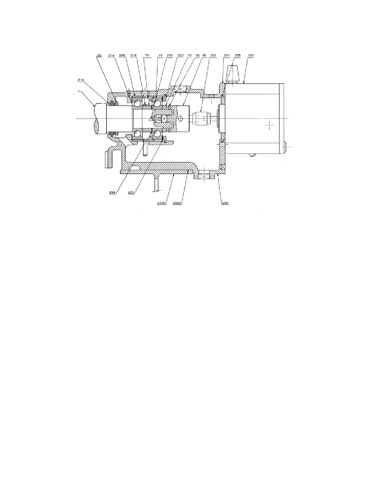
Some governors are direct-drive types coupled to the end of the turbine shaft by
couplings, as shown in Figure L-11. Others, due to speed requirements, are
connected by right-angle gear reduction units, as shown in Figure L-12.
L.12.2
Governor Removal (Direct Drive)
a. Drain oil from governor (300) at drain.
b. Disconnect connecting rod
(1075) at governor lever
(445) by removing
connecting rod end (1070). Do not disturb position of rod end (1070) bearing
on rod (to preserve open/close stroke adjustment).
c. Rotate turbine shaft (1), if necessary, to disengage coupling hub (303) by
loosening coupling setscrew.
d. Prop or support governor (300); then, unbolt governor from mounting housing
(201) and slide governor out of mounting housing. Be careful not to lose the
governor key.
e. Remove governor trip latch (446) (if same governor is not to be used as
temporary replacement) by loosening its setscrew.
SST Turbine Instruction Manual
Revision A
223
Low Voltage Electrical Components
SST Turbine Instruction Manual
Figure L-11. Direct Drive Governor Assembly
L.12.3
Governor Replacement (Direct Drive)
a. Install governor trip latch (446) and tighten lever set-screw securely.
b. Slip coupling spider between jaws of coupling (303) hub on turbine shaft
extension.
c. Install coupling hub (303) on governor shaft.
d. Slide governor (300) into place on mounting housing (201), verifying that
coupling (303) engages properly.
e. Install and tighten screws to secure governor to mounting housing (303). There
should be 1/16 inch (1.6 mm) play for the coupling spider between coupling
hubs. Coupling access is available through the open side of the mounting
housing. Tighten screw to secure coupling.
f.
Reconnect connecting rod (1075).
g. Remove governor breather cap and fill governor with oil to proper level
indicated on sight glass.
224
Revision A SST
Turbine
Instruction
SST Turbine Instruction Manual
Low Voltage Electrical Components
h. Rotate turbine shaft (1) slowly by hand to ensure that governor and coupling
are free to turn when placed in operation.
L.12.4
Governor Removal (Gear Drive)
a. Drain oil from governor (300).
b. Disconnect connecting rod
(1075) at governor lever
(445) by removing
connecting rod bolt. Do not disturb position of rod end bearing on rod (to
preserve open/close stroke adjustment).
c. Remove cap screws securing governor (300) to gearbox (316) adapter; then,
lift governor vertically from adapter. The coupling (303) will remain on the
governor shaft at removal. Do not remove governor lever or coupling from
governor if same governor is to be installed again. If a new governor is to be
installed, transfer lever and coupling (with keys) to new governor. The lever
and coupling are secured to governor shafts by setscrews.
Note: The coupling, which joins the governor and gearbox shafts, is supplied with
the gearbox.
L.12.5
Governor Replacement (Gear Drive)
a. Verify that coupling and keys are installed on governor shaft, and that the
governor lever is mounted to its shaft at the side of the governor.
b. Lower governor (300) on gearbox (316) adapter with coupling key slots
positioned to allow mating of keys and key slots of shaft and coupling (303) as
governor and adapter flanges meet.
c. Rotate governor to align cap screw holes; then, install cap screws tightly.
L.12.6
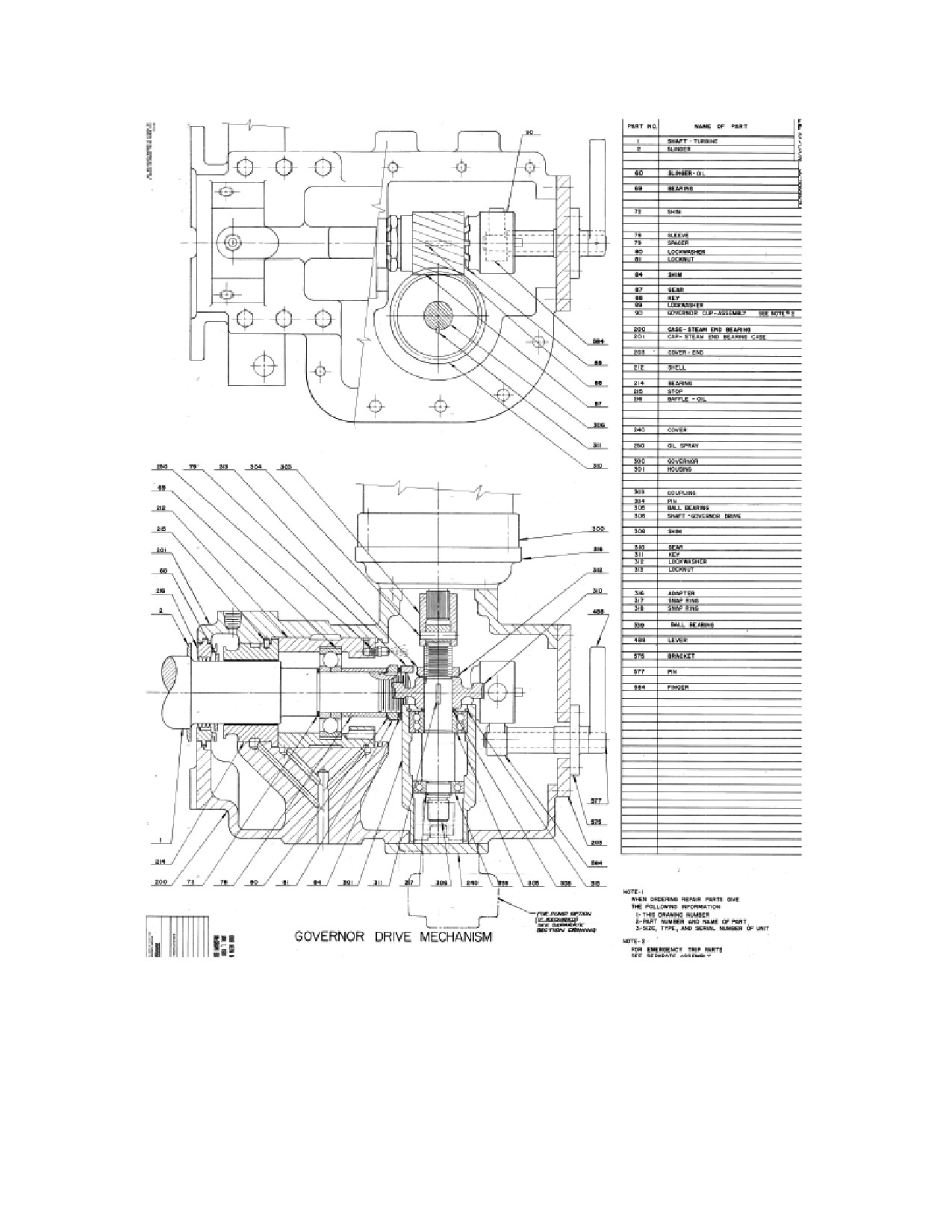
Governor Drive Gearbox Removal
The governor (300) must be removed according to the procedure specified in
Section L.12.4, above, before the gear (310) and governor drive shaft (306) can be
removed.
a. Drain oil from steam end bearing case (200).
b. Remove pin (304) from coupling (303) to release coupling from governor
drive shaft (306).
SST Turbine Instruction Manual
Revision A
225
Low Voltage Electrical Components
SST Turbine Instruction Manual
Figure L-12. Gear Drive Governor Assembly
226
Revision A SST
Turbine
Instruction
SST Turbine Instruction Manual
Low Voltage Electrical Components
c. Remove lock-nut (313) and lock washer (312) retaining gear onto governor
drive shaft (306). Slide gear (310) up off of shaft (306), being careful not to
lose key (311).
d. Remove shim (308) being careful to document order of removal/replacement.
e. Remove snap ring (318) retaining bearing into housing (301). At this point the
governor drive shaft (306) can be extracted from the housing (301).
f. Prop or support governor drive shaft (306) in a vice being careful not to scar the
shaft surface and remove the snap ring (318) retaining the ball bearing (339).
At this point both ball bearings (339) and (305) can be pressed from the
governor drive shaft (306) for replacement.
The Dresser-Rand factory maintains a stock of replacement governor drive shaft
parts for rapid delivery to the user, and is equipped to perform complete repair and
overhaul service on gearboxes.
L.12.7
Governor Drive Gearbox Replacement
a. Install governor drive shaft (306) into housing (301) and install snap ring
(318). Replace shim (308), locate key (311) into slot on governor drive shaft
(306) and install gear (310), lock washer (312) and lock-nut (313) securing
gear onto governor drive shaft (306).
b. Install coupling (303) and pin (304) into and onto governor drive shaft (306).
c. Before installing the governor, check and record the backlash of the new gear.
In future inspections, use this dimension as a guide in determining the
necessity for replacement. If backlash is questionable use Dyken layout blue
or printers ink to check for proper mesh of gears. When a good mesh is
indicated, the gear may remain in service.
c. Mount governor (3004) onto housing (316), verifying that the splines on the
governor shaft slide into the coupling (303) easily. Install mounting bolts to
secure governor (300) onto housing (316).
d. Fill hydraulic governor with oil. Refer to Woodward Bulletin
25071 in
Appendix B.
e. Fill steam end bearing case (200) with recommended lubricant to required
level, as indicated by oil sight gage plug.
L.12.8
Governor Valve Travel and Linkage Adjustment
SST Turbine Instruction Manual
Revision A
227
Low Voltage Electrical Components
SST Turbine Instruction Manual
Refer to the following figures:
M-1
Trip Throttle Valve Assembly
M-2
Governor, Mounting Housing, and Trip Components
L-11
Direct Drive Governor Assembly
L-12
Gear Drive Governor Assembly
L-13
Trip Valve Linkage
Adjustment of the linkage between the governor and throttle should be carried out
whenever linkage components, or the governor itself, are replaced. Rig the throttle
linkage as follows:
a. Check that the governor linkage is approximately at right angles to governor
connecting rod.
(See upper view of figure L-13). Adjust the length of the
connection rod as necessary.
b. Back off the lock nuts on both sides of the governor lever block.
c. Pull the connecting rod out of the Woodward governor as far as it will go.
d. Push the connecting rod back toward the governor 3/16”/4.76mm. (To hold
this position while making the adjustment, place a block equal to the existing
clearance between the connecting rod end and the mating fitting on the
governor—see lower view in Figure L-18.
e. Push the valve stem in until the valve just seats.
f. Tighten the lock nuts on both sides of the governor lever block to secure
the ajdustment.
L.13
Trip and Throttle Valve Maintenance
CAUTION
228
Revision A SST
Turbine
Instruction
SST Turbine Instruction Manual
Low Voltage Electrical Components
If the turbine is equipped with a throttle or trip valve
manufactured by a party other than Dresser-Rand refer to the
accessory documentation section of this manual for installation,
operation, and repair and maintenance instructions.
Refer to the following figures:
M-1
Trip and Throttle Valve Assembly
M-2
Governor, Mounting Housing, and Trip Components
L-13
Trip Valve Trip Linkage
L-14
Throttle Valve Trip Linkage
The design of the Dresser-Rand trip and throttle valve assembly permits routine
maintenance (disassembly and assembly) procedures while still mounted on the
turbine and without disconnecting the inlet piping. For major overhaul or
necessary machine work, remove the valve as indicated below.
WARNING
BEFORE SERVICING ANY COMPONENT of the combo valve,
verify that the ISOLATING VALVE in the INLET LINE is
CLOSED AND TAGGED. If the turbine is connected to the
exhaust steam header, CLOSE the ISOLATING VALVE in the
EXHAUST LINE AND TAG IT. OPEN ALL TURBINE DRAINS
to ensure venting of all pressure before disassembly begins.
CAUTION
In the following procedures, remove and replace all parts slowly
and carefully to avoid damage (digs, bends, scoring, chipping,
etc.) to conditioned surfaces. DO NOT use excessive force to
remove parts. Use backup bracing for unsupported parts when
taper pins or dowels are removed by hammer and drifts.
L.13.1
Valve Removal from Turbine
The steam strainer should be removed and cleaned at least once a year and
replaced every three years. Since it is necessary to remove the governor
valve before the strainer can be withdrawn, the governor valve and its seats
should be inspected and reground if necessary. To replace either the
SST Turbine Instruction Manual
Revision A
229
Low Voltage Electrical Components
SST Turbine Instruction Manual
governor valve or the steam strainer, proceed as follows:
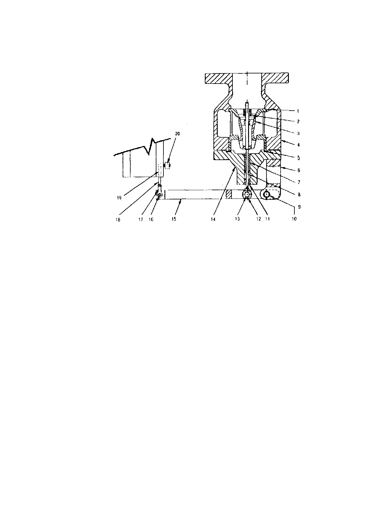
(See Figure L-
14).
a.
Remove valve adjusting nut and washer.
Note: Do not disturb settings of lock nuts and connecting rod-ends (17 and 19) on
rod (18) unless parts need to be replaced. These are factory-set to provide
the required stroke for the rod.
b. Remove snap ring from the governor lever pin; then remove the pin and
carefully slide the governor lever off the governor valve stem.
c. Remove the nuts that secure the steam chest cover to the steam chest and
carefully remove the cover without contacting the valve stem.
d. Pull out the governor valve (see governor section, Appendix A).
e. Remove bolting at turbine flange; then, lift valve by slings and hoist to service
area for further disassembly.
f.
Remove as an assembly together with the steam strainer.
g. Perform necessary maintenance and reassemble by reversing the removal
procedure.
h. After completing installation, set the following:
Overspeed Trip
Overspeed Trip Linkage
Governor Valve Travel
230
Revision A SST
Turbine
Instruction
SST Turbine Instruction Manual
Low Voltage Electrical Components
Finger 22
21
20
3 Valve Seat Bushing
Stem
Strainer
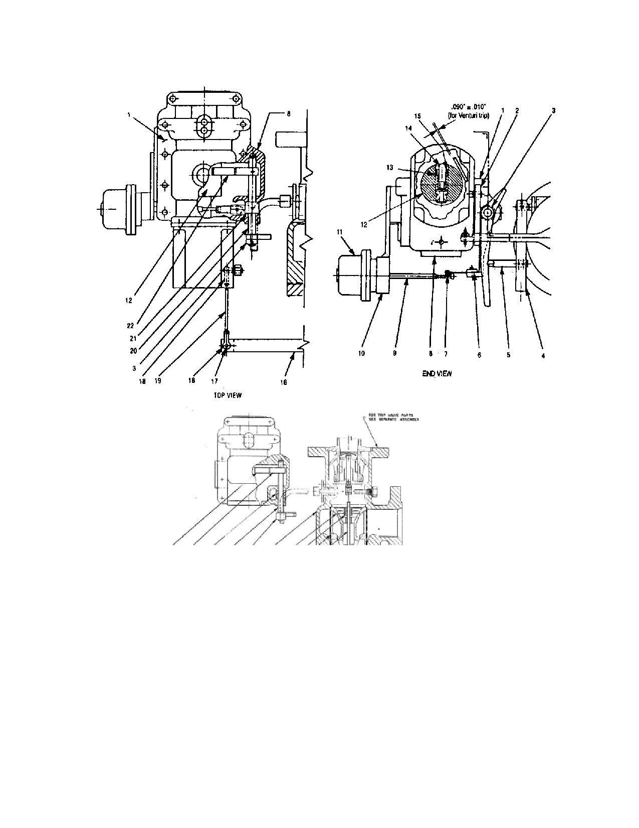
Figure L-13. Overspeed and Governor Valve Linkage
Legend
15. Lockscrew
1. Cap
8. Case - Steam End
16. Lever - Governor
2. Lever
9. Steam - Bellows
17. Pin
3. Lever - Trip
10. Bracket - Low Oil Trip
18. Rod End
4. Lever - Trip Connection
11. Low Oil Trip
19. Rod - Connecting
5. Rod - Trip Connection
12. Governor Cup
20. Shaft - Trip
6. Plate - Top
13. Adjusting Screw
21. Collar
7. Latch - Trip Assembly
14. Emergency Weight
22. Trip Finger & Lever
SST Turbine Instruction Manual
Revision A
231
Low Voltage Electrical Components
SST Turbine Instruction Manual
Figure L-14. Throttle Valve Linkage
Legend
1. Bushing - Valve Seat
8. Stem - Valve
14. Cover - Steam Chest
2. Bushing — Valve Stem
9. Pin
15. Lever - Governor
3. Valve
10. Bearing
16. Pin
4. Steam Chest
11. Bushing - Valve
17. Rod End
5. Gasket
Stem-Outer
18. Rod- Connecting
6. Bracket - Governor Lever
12. Block - Pivot
19. Rod End
7. Bushing - Valve Stem - Inner13. Block - Sliding
20. Lever
L.13.2
Woodward TG Governor Valve Travel Setting
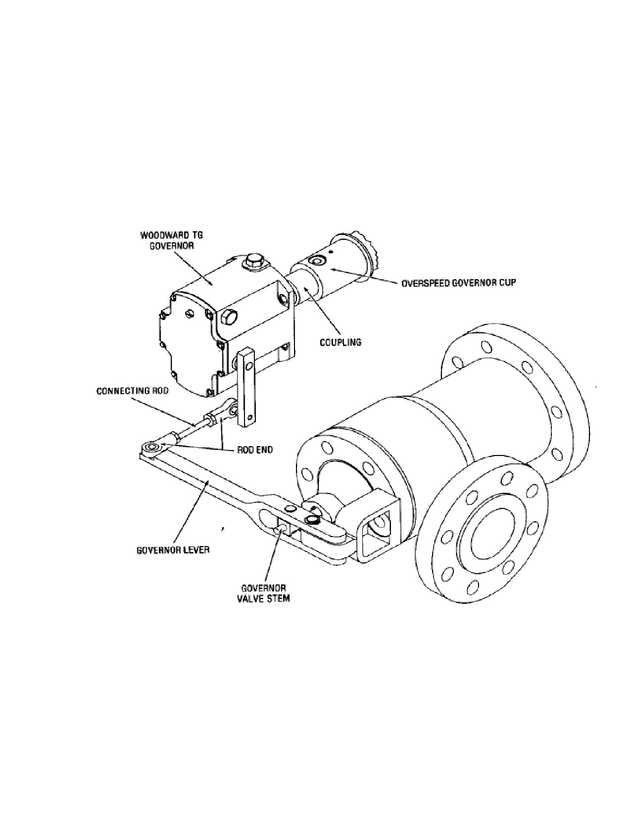
a. Remove pin that connects the governor lever to the connecting rod end.
(See Figure L-15.)
b. Push the governor lever in until valve just seats and hold this position.
c. Push connecting rod toward the valve closing direction (see arrow on
illustration) as far as it will go and hold this position.
d. Adjust the length of the connecting rod so that the hole for the pin in the
rod end is approximately 1/8”/3.75mm beyond the mating hole in the
governor rod.
e. Release the connecting rod and insert the connecting pin.
L.13.3
Woodward TG-13L Governor with Fisher Control
232
Revision A SST
Turbine
Instruction
SST Turbine Instruction Manual
Low Voltage Electrical Components
The Fisher pneumatic speed mechanism acts in conjunction with the Woodward
TG-13L governor to adjust the turbine speed to refined limits. If speed re-
adjustment is desired, re-locate the pin to another hole in the lever (see Governor
Speed Control Schematic, Appendix A).
The Fisher control can be used as a direct or reverse type control; either to increase governor
speed settings as control air pressure signal increases, or the reverse type to increase governor
speed as control air pressure signal
decreases.
Figure L-15. Governor Valve Travel Setting - Woodward TG Governor
SST Turbine Instruction Manual
Revision A
233
Low Voltage Electrical Components
SST Turbine Instruction Manual
L.13.4
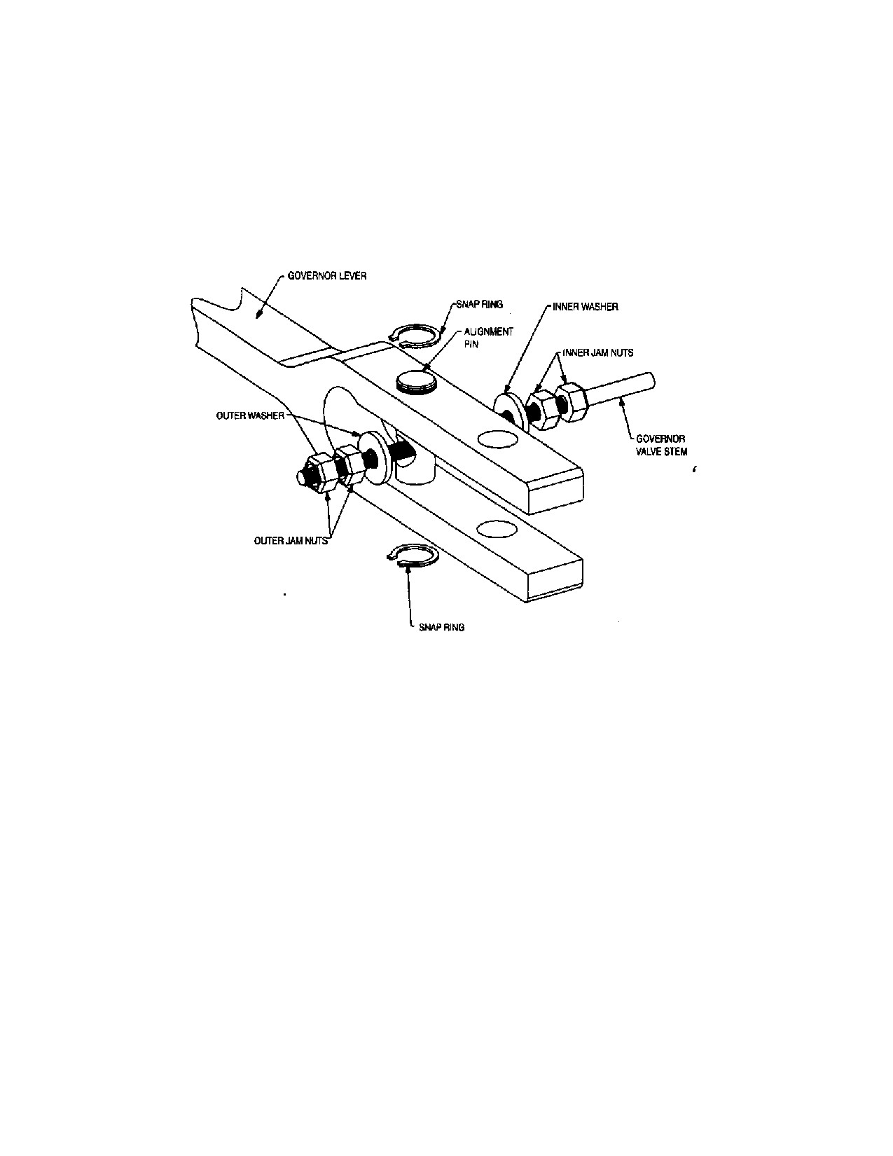
Alternate Governor Valve Stem Connection
Some Dresser-Rand turbines may be equipped with an alternate method of securing
the governor valve stem to the rotating governor lever. This connection should be
installed so that the inner and outer washers are tight against the alignment pin.
The operator should be able to turn the washers by hand with no lost motion after
tightening the inner and outer jam nuts.
Figure L-16 Alternate Governor Valve Stem Connection
234
Revision A SST
Turbine
Instruction
SST Turbine Instruction Manual
Low Voltage Electrical Components
L.14
Emergency Valve Maintenance
WARNING
BEFORE SERVICING ANY COMPONENT of the Overspeed
Trip Mechanism, verify that the ISOLATING VALVE in the
INLET LINE is CLOSED AND TAGGED. If the turbine is
connected to the exhaust steam header, CLOSE the
ISOLATING VALVE in the EXHAUST LINE AND TAG IT.
OPEN ALL TURBINE DRAINS to ensure venting of all pressure
before disassembly begins.
The overspeed trip mechanism may be readily disassembled or assembled at a
workbench and then mounted to the turbine as a subassembly. Prerequisites for this
process are removal of the governor and coupling according to the procedure
specified in Section L.12, followed by removal of the overspeed trip collar (90)
from shaft (1), as described below.
It is important that the entire emergency trip system be properly adjusted and free
of binding or lost motion. The operation of the overspeed trip should be tested as
often as possible, especially at times that maintenance is performed and a
permanent record should be kept of these tests. The over-speed trip should
function to shut down the turbine within 2% of the speed specified on the turbine
data sheets. If the operational tests in Section I.6 indicate a requirement for
adjustment, proceed as follows:
L.14.1
Governor Cup Removal
Refer to the following figures:
L-13
Overspeed and Governor Valve Linkage
L-14
Throttle Valve Linkage
L-15
Governor Cup Assembly
a. Gain access to the overspeed governor cup.
For turbines with a Woodward gear driven governor - remove bearing
case end cover.
For turbines with a Woodward governor that is coupled to the shaft -
remove the steam end bearing case cap.
SST Turbine Instruction Manual
Revision A
235
Low Voltage Electrical Components
SST Turbine Instruction Manual
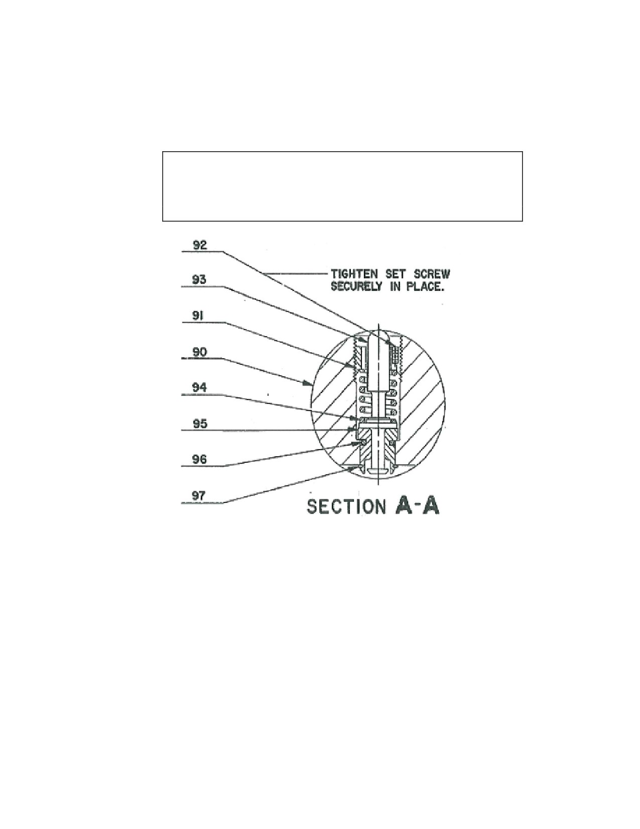
b. Manually rotate the turbine shaft (1) until the lock screw (P/N 15, Figure L-13
or P/N 92, Figure L-15) is accessible; then loosen the lock screw.
CAUTION
If the Overspeed Governor Cup Assembly is replaced, the rotor
may need to be re-balanced with the new assembly attached.
Figure L-17. Governor Cup Assembly
Legend:
90. Cup - Governor
94. Spring
91. Screw - Adjusting
95. Bushing - Weight
92. Set Screw
96. Ring - Retaining-Open type
93. Weight
97. Ring - Retaining-External type
b. Using a suitable spanner tool, turn the adjusting screw (91) clockwise to raise
the tripping speed or counterclockwise to lower, as necessary.
c. Tighten the lock screw (15 or 92) (setscrew) securely to lock the adjustment
position, then repeat the over-speed trip test (see warning below).
236
Revision A SST
Turbine
Instruction
SST Turbine Instruction Manual
Low Voltage Electrical Components
WARNING
The overspeed trip assembly should be locked in place before
starting the turbine. Four checks to make are as follows:
1. The overspeed governor cup must be tightly screwed into
the shaft.
2. If supplied, one of the tabs of the lock-washer is bent into
the miller slot of the overspeed cup.
(The overspeed cup will
have two milled slots for the tabs of the lock-washer, but it will
only be possible to line up one of the tabs. This is due to the
fact that the tabs are not symmetrically located around the
outer diameter. There is no need for concern as long as one of
the tabs can be completely bent over into the slot.)
3. If the overspeed cup has drilled and tapped holes for half
dog point set screws, the shaft must be drilled at final assembly
with the overspeed cup in accordance with the table below to
ensure the tip of the dog point locks into the shaft. The set
screws must be tightened and staked into place.
4. The run-out of the cup must also be checked and adjusted
to within 0.002 inch (.05 mm) total indicated run-out.
L.14.2
Governor Cup Replacement
SST Turbine Instruction Manual
Revision A
237
Low Voltage Electrical Components
SST Turbine Instruction Manual
CAUTION
The adjusting screw/spring combination has been pre-set at the
factory for the trip speed originally set when the turbine was
shipped. Refer to Section L.14.7, Trip Linkage Adjustment, if
minor trip speed changes are to be made.
WARNING
Adjusting Screw (91), spring (94), and setscrew (92) are a
FACTORY-CONFIGURED SET, selected to obtain the proper
trip speed for a specific turbine. DO NOT MIX OR
INTERCHANGE THESE PARTS with similar parts from other
turbines or attempt to modify these components. Consult your
local Dresser-Rand manufacturer’s representative or the factory
if replacement parts are needed.
L.14.3
Trip Mechanism Disassembly
For 4” and 6” trip and throttle valve systems, the clearance between the overspeed trip
lever (Figure L-13) and the emergency weight (P/N 14) or (P/N 93 in Figure L-14) is
properly set at the factory for 0.060”/1.524mm plus or minus 0.010”/0.254mm. Gain
access to the over-speed governor cup as described in the preceding section L.14.1.
For 4” and 6” Venturi trip systems, the clearance between the over-speed trip lever
(figure L-13) and the emergency weight (P/N 14 or P/N 93) is properly set at the factory
for (0.090”/2.286mm plus or minus 0.010”/0.254mm. Gain access to the overspeed
governor cup as described in section L.14.1.
Rotate the turbine shaft (1) to position the overspeed weight adjacent to the overspeed
trip lever and measure the clearance. If adjustment is necessary, proceed as follows:
a. Loosen lock screw that secures the valve lever trip connection to the valve
spindle.
b. Slide valve lever connection along the valve spindle away from the steam
chest to increase the clearance, toward the steam chest to decrease the
clearance.
c. Tighten the lock screw to securely hold the valve lever connection.
238
Revision A SST
Turbine
Instruction
SST Turbine Instruction Manual
Low Voltage Electrical Components
L.14.4
Emergency Valve Travel
a. Unlatch valve lever (P/N 3, Figure L-13) to close emergency valve.
b. Manually pull out on the governor linkage to close the governor valve. On the
turbine, it may be necessary to remove the pin from the connecting rod. (See
lower view of Figure L-18)
c. With the governor valve fully closed, raise the valve lever until the emergency
valve will not open further (do not spring the valve lever).
d. Measure the clearance between the latch surface of the valve lever and the
latch surface of the trip lever. The clearance should be approximately ¼”/6.35
mm.
e. If adjustment is required, loosen the lock screw in the valve lever connection;
then reposition the valve lever connection and serrated valve spindle clockwise
or counter-clockwise as necessary to obtain the correct clearance.
NOTE: After making this adjustment, it will be necessary to re-check the
setting of the over-speed trip linkage.
L.14.5
Emergency Valve Removal and Replacement
a. Remove governor valve and steam strainer as described in section L.13.1.
b. Remove lock screw in the valve lever connection; then slide the valve lever
connection off the serrated valve spindle.
c. Remove access plug in the steam chest located above the valve spindle; then
remove the lock screw that secures the valve spindle to the valve link.
d. Remove access plug in the steam chest in line with the valve spindle and
withdraw the valve spindle.
e. Remove the valve link by sliding up and away from the valve stem.
d. Remove the valve portion of the assembly and inspect the valve seat.
NOTE: If the valve seat must be replaced, the steam chest must be removed from
the turbine.
e. Re-assemble and install the emergency valve by reversing the removal
procedure.
SST Turbine Instruction Manual
Revision A
239
Low Voltage Electrical Components
SST Turbine Instruction Manual
4
5
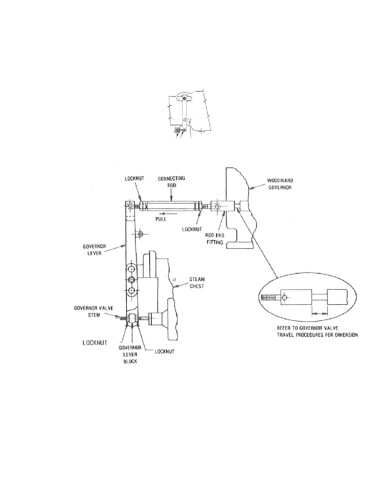
Figure L-18. Trip Valve Lever Orientation-Trip Valve Open and Closed
After completing installation, set the following:
240
Revision A SST
Turbine
Instruction
SST Turbine Instruction Manual
Low Voltage Electrical Components
Overspeed trip
Overspeed trip linkage
Governor valve travel
Emergency valve travel
L.14.6
Trip and Throttle Valve and Steam Strainer
The following are procedures for replacement of the steam strainer:
a. Close the main steam valve.
a. Disconnect the pressure and drain line connections at the oil cylinder flanges.
c. Disconnect the linkage from the governor lever.
d. Remove the bolts that fasten the trip throttle valve body to the valve body
cover.
e. Remove the bolts that fasten the valve body cover to the valve body; then lift
off the valve body cover.
f.
Lift out the emergency valve guide.
g. Pull out the steam strainer.
h. Perform the necessary maintenance and re-assemble by reversing the removal
procedure.
i.
For procedures on a vendor valve, see Appendix B.
NOTE: The 6” trip and throttle valve cover is equipped with a throttle screw that
regulates the amount of steam from the inlet side of the valve to the chamber
above the main disc. If chattering of the main disc is encountered when
opening the valve, it is necessary to increase the leakage to the chamber by
turning the throttle screw counter-clockwise. If, however, the hand-wheel
effort appears excessive, it can be reduced by turning the throttle screw
clockwise, thus decreasing the leakage to the chamber. A pipe tap is provided
in the cover to be used for a pressure gauge to check the pressure chamber
after the pilot valve has been opened. This leakage pressure should be
approximately 25% of the line operating pressure.
SST Turbine Instruction Manual
Revision A
241
Low Voltage Electrical Components
SST Turbine Instruction Manual
Section M
Replacement Parts/Factory Service
M.1
Factory Replacement Parts
Dresser-Rand Turbine recommends that only Dresser-Rand-supplied parts be used
in Dresser-Rand turbines. The use of Dresser-Rand parts ensures that replacement
components are manufactured from the highest quality materials, to exacting
tolerances and specifications, thereby assuring safe, efficient, long-lasting, and
maintenance-free operation under service conditions for which the turbine was
designed and built.
Dresser-Rand and selected Dresser-Rand manufacturer’s representatives maintain a
supply of the most frequently requested spare parts for immediate shipment
worldwide. Parts requested less frequently can be manufactured quickly on an
emergency basis when required.
Your Dresser-Rand manufacturer’s representative can supply you with a stocking
list of recommended spare parts for your turbine or turbines, allowing you to stock
spare parts at your facility. Refer to Section M.4, Recommended Spare Parts.
M.2
Turbine Identification
Dresser-Rand SST turbines are marked with a serial number, which appears on the
nameplate and is also, stamped on horizontal flange of the inlet casing. This serial
number is used by the factory to identify the turbine and should be used in all
inquiries and parts orders.
M.3
Parts Identification
When inquiring to determine parts availability, or when placing an order for spare
parts, the following minimum information is required:
Item
Typical Example
Turbine serial number:
XXXX
Part description:
Shaft
Reference number:
21
242
Revision A SST
Turbine
Instruction
SST Turbine Instruction Manual
Low Voltage Electrical Components
Section Drawing
LE-169235-N
If the turbine parts list is available, then the Dresser-Rand part number should also
be specified.
WARNING
Modification of, incorrect repair of, or use of non-DRESSER-
RAND repair parts on this turbine could result in serious
malfunction or explosion that could result in serious injury or
death. Such actions will also invalidate ATEX Directive &
Machinery Directive Certifications for turbines that are in
compliance with those European Directives. Refer to Section M
- Replacement Parts/Factory Service.
M.4
Recommended Spare Parts
The recommended spare parts for a turbine owner is provided in the service
manual. The inventory recommendation for spare parts is based on Dresser-Rand’s
long experience with turbine applications.
M.5
Ordering Parts
Contact your local Dresser-Rand manufacturer’s representative to order parts. Your
representative will be pleased to provide any assistance you may require, as well as
to quote prices and delivery dates.
The following information is required when placing a parts order:
1.
Your purchase order number.
2.
Complete billing, shipping, and marking instructions.
3.
Turbine serial number--from nameplate or horizontal flange of inlet casing.
4. Turbine frame size--from nameplate, i.e., 300, 500, 700, etc.
5. Quantity of each part or assembly.
6.
Part or assembly reference number from drawing, illustration, or text.
7. Section drawing the reference number was taken from.
8. Description of part or assembly.
SST Turbine Instruction Manual
Revision A
243
Low Voltage Electrical Components
SST Turbine Instruction Manual
9. Dresser-Rand part number, if known (optional).
M.6
Service
Dresser-Rand Turbine maintains repair facilities on a worldwide basis to repair
equipment needs with OEM manufactured parts. When contacting Dresser-Rand,
please have your turbine serial number available.
Contact a service center nearest you by using the link below:
A Service Representative can also be dispatched to your site to assist you in start-
ups, general maintenance, and troubleshooting by using the same link (above).
Have your turbine serial number available along with a date for when services will
be required.
The Technical Support group at the factory can address your technical questions by
using the contact information below:
Dresser-Rand Wellsville Operations
37 Coats St.
Wellsville, NY 14895
USA Tel: (Int’l +1) 585-596-3100
Fax (Int’l +1) 585-593-5815
When contacting the representative or factory, please specify the turbine serial
number, frame size, nature of the problem or service requirement, and date that
service is required.
M.7
Revamps (Rerates)
It’s not uncommon for the requirements of the steam turbine to change due to a
process change, more product output, or just a need to reduce energy consumption.
Steam turbine can have a broad operating range. Powers and speeds can be
modified with simple internal hardware changes while still maintaining the same
steam turbine case and footprint.
If you would like to have Dresser-Rand review your equipment, please use the
contact information above the find the nearest service center or contact the factory
direct. Have your serial number available along with the new conditions you
would like to operate at.
244
Revision A SST
Turbine
Instruction
SST Turbine Instruction Manual
Low Voltage Electrical Components
WARNING
Materials used in turbine construction (cast iron, steel, stainless
steel, special alloys) vary with steam conditions, speed, and
power. These materials were selected according to the original
rating of the turbine. NEVER attempt to re-rate a turbine without
the assistance of a Dresser-Rand manufacturer’s
representative and/or the factory. Misapplication of materials
could result in serious equipment damage and/or personal
injury.
M.8
Upgrades
Many of older turbines can be modified or upgraded to improve performance and
reliability. Improved designs in seals, bearings, controls, and blading can all be
incorporated into the existing machine when required.
If you would like to have Dresser-Rand review your equipment, please use the
contact information above and find the nearest service center or contact the factory
direct. Have your serial number available.
M.9
Factory Start-Ups
Authorized Dresser-Rand service representatives are available for start-up service
and to train operating personnel in the operation and maintenance of Dresser-Rand
steam turbines. An experienced service representatives will review your installation
prior to start-up, following established Dresser-Rand procedures.
Piping,
alignment, lubrication, overspeed trip, etc. will be carefully checked. Upon
commissioning the new installation, operating personnel will be trained.
Consult your Dresser-Rand manufacturer’s representative to schedule a start-up.
M.10
Parts Catalog
Refer to the applicable turbine cross sectional drawings included in the instruction
manual for a listing and location of the replacement part reference numbers used on
your turbine.
SST Turbine Instruction Manual
Revision A
245
Low Voltage Electrical Components
SST Turbine Instruction Manual
Section N Miscellaneous
N.1
Low Ambient Temperature Applications of Single
Stage ASTM A216-WCB Carbon Steel Pressure
Casing Steam Turbines
Dresser-Rand has been asked to provide a quotation for steam turbines that may be
installed into an area with an ambient temperature of -30°C (-20°C) or less.
The quoted D-R single stage turbine is offered with ASTM A216 Grade WCB
carbon steel pressure casing material that will meet the Charpy V-Notch Energy
requirements of ASME Pressure Vessel Code Section VIII, Division 1, UG-84 as
required by API 611 for ambient temperatures -30°C (-20°F) or higher. The
pressure vessel bolting is ASTM A193 Grade B7, and nuts are ASTM A194 Grade
2H or ASTM A563 Grade A, which also meet the requirements of the Pressure
Vessel Code and API 611for ambient temperatures of -30°C (-20°F) or higher. If
the offered turbine is installed into an area with ambient temperatures of lower than
-30°C (-20°F), the equipment user must take precautions to insure that the turbine
casing be kept warm and/or be warmed prior to equipment start-up to meet the
requirements of ASME Section VIII, Division 1, UG84, as appropriate.
When a steam turbine is in operation, the casing temperature s above the
brittle/ductile transition temperature of the casing material. Therefore, a low
ambient temperature is not a concern. However, to insure that the low ambient
temperature does not result in damage or failure of the turbine and its accessories, it
must be installed, started, operated, and shut down as described in the Low
Ambient Steam Turbine Application Guidelines outlined below. If compliance
with these guidelines and acceptance of the offered standard materials is not
possible, consult Dresser-Rand for further discussion or an alternate material
offering.
Prior to the purchase of the turbine, the final equipment user, driven equipment
vendor, and Dresser-Rand shall agree to the special precautions necessary with
regard to low ambient conditions that can occur during operation, maintenance,
transportation, erection, commissioning, and testing.
Dresser-Rand shall assume no liability of any nature for the offered turbine if not
transported, erected, installed, started, operated, maintained, and shut down as
described in compliance with the
“Low Ambient Steam Turbine Application
Guidelines” outlined in this document.
246
Revision A SST
Turbine
Instruction
SST Turbine Instruction Manual
Low Voltage Electrical Components
Low Ambient Steam Turbine Application Guidelines
Note these requirements apply to both API and non-API applications.
General:
When a steam turbine is to be installed where the ambient temperature could be -
30°C (-20°F) or lower, the following issues require special attention to insure that
the low temperature does not result in damage or failure of the turbine and/or its
accessories.
See the turbine instruction manual for additional turbine installation and
operational details and the accessory instruction manuals for their cold start/low
ambient precautions and recommendations.
Transportation:
The turbine is suitable for transporting to site, unloading, and placing in storage, or
transporting to site, unloading, and placing on its foundations, or moving from on-
site unheated storage to its foundations, only when ambient temperature is at or
above -30°C (-20°F).
Installation:
The turbine and its auxiliaries can remain out of service with no external source of
heat when the ambient temperature is at or above -45°C (-49°F), provided the
turbine is not disturbed when its metal temperature is below
-30°C (-20°F),
Turbine maintenance cannot occur unless the temperature of the turbine and all its
mechanical components is at or above -30°C(-20°F).
Turbine installation cannot proceed until the turbine and all its mechanical
components are t or above -30°C (-20°F). Alternatively, if the turbine components
are below -30°C (-20°F), the area musts be hooded and heated to raise the
component temperature above -30°C (-20°F).
Care must be taken to insure that the steam inlet and exhaust piping is properly
supported or equipped with flexible connections so they will not put excessive
force on the turbine when it is shut down. The turbine casing and inlet and exhaust
flange material are more prone to cracking when the ambient temperature is cold ad
their temperature is below the brittle/ductile transition temperature. This is of
increased concern if the piping is hot when the turbine is shut down and the inlet
and exhaust shut off valves are closed.
SST Turbine Instruction Manual
Revision A
247
Low Voltage Electrical Components
SST Turbine Instruction Manual
All turbine condensate drain connections and steam piping low points must be
properly drained to insure all condensate can be removed from the turbine and
steam system during shot-down. Similarly, cooling water lines to bearing housings
and water coolers, bearing housing water jackets, and oil coolers must be equipped
with drains to insure that water can be removed during shut-down.
Failure to remove all water from the turbine casing, piping, cooler,, bearing
housing, etc. when temperatures are below freezing could result in failure of the
piping and various other components.
If oil reservoirs, oil or water piping, bearing housings, and other components are
heat-traced, all local safety regulations and electrical codes must be adhered to.
Lubrication:
Dresser-Rand offers a variety of lubrication systems including oil ring lubrication,
oil ring lubrication with circulating oil cooling, circulating oil lubrication, mist oil
lubrication, and force feed lubrication.
When the ambient temperature is 15°C (60°F) or lower, it must be ensured that the
lubricating oil will circulate and that cooling water, if required, does not freeze
during operation or shut-down. Heat tracing or insulation of oil lines, bearing
housing, oil tanks, and water cooling lines may be required. Lubricant type and
required oil viscosities for turbine equipment packages are defined in the certified
drawings and data package and the applicable operation and maintenance manuals.
Viscosities for turbine lubrication are application specific, and the required
viscosity may range from ISO 32 (32cSt@40°C (100°F) 150 SUS @40°C (100°F)
up to ISO 100 (100 sSt @ 40°C (100°F) 550 SUS@40°C (100°F),
Use of the correct lubricants at the correct temperatures and viscosities is critical to
the trouble free operation of the turbine and its accessory equipment.
Accessories:
Some turbine accessories may require installation, heat tracing, special lubrication,
or adjustments for use in low ambient conditions. Others may require installation
into heated locations or preheating before use. The accessory instruction manuals
or accessory vendor must be consulted for additional guidance and precautions.
A partial list of typical turbine accessories might include governors, gauges, oil
pumps, control panels, instruments, reduction gears, lube oil systems, couplings,
steam piping, valves, solenoid valves, tachometers, ejectors, condensers, etc.
Turbine Start-Up:
248
Revision A SST
Turbine
Instruction
SST Turbine Instruction Manual
Low Voltage Electrical Components
Warming the Turbine Pressure Casing:
If metal temperature is at or below -30°C (-20°F), a warm-up of the complete
turbine must be performed prior to start-up, including the use of hooding and space
heating to elevate the metal temperature of all steam-contacted components to a
temperature of at least -30°C (-20°F) prior to the introduction of steam to the
turbine.
If metal temperature is above -30°C (-20°F), steam from the client’s exhaust steam
header piping may be used to preheat the cold back pressure turbine prior to start-
up. If exhaust steam is not available for this purpose, a small steam bypass line,
equipped with a valve, may be installed around the inlet block valve or start-stop
valve to allow preheating of the turbine casing with a small flow of inlet steam.
Allow the turbine casing to reach 15°C (60°F) or exhaust steam temperature before
proceeding further.
During warming, all turbine casing and associated steam piping drain valves must
be opened to allow liquid to drain from the turbine casing and its associated steam
piping. Take special care to insure all liquids are drained prior to closing the
valves for turbine start-up.
Prepare the Lubrication System for Start-Up
If the ambient temperature is less than 15°C (60°F), lubricating oil and, if supplied,
the lubrication system and oil piping must be warmed to 15,C (60°F) to insure that
the oil will flow to the bearings and back to the oil reservoir or oil tank.
For ring-oiled turbines, the oil temperature should be such that the oil rings will
turn and pick up the oil. This may require that a hot liquid be circulated through
the bearing housing “cooling” water jackets.
“Cooling water,” if less than 15°C
(60°F), which may be required during normal turbine operation, should not be
applied to the bearing housing water jackets until the bearing housing temperature
exceeds 15°C (60°F), which may be required during normal turbine operation. For
turbines equipped with pressure lubricating or circulating oil systems, the lubricant
must be warmed to a viscosity such that the oil pump will prime and deliver
lubricant to the turbine bearings. His may be accomplished by use of a steam
heating coil or electric heating element. If electric heating elements are used, the
watt density should not exceed 23W/in² (3.5W/cm²), and a sheath temperature of
100°C (212°F) to avoid carbonizing the oil. After the lubricant is warmed, it must
be circulated throughout the entire lubrication system by means of a hand, motor,
or steam driven pump to warm all the associated lubrication system components
prior to turbine start-up.
SST Turbine Instruction Manual
Revision A
249
Low Voltage Electrical Components
SST Turbine Instruction Manual
After heating the lubricating oil or determining that it does not require heating, start
the turbine per the instruction manual. Turn the turbine over slowly for a short
time, insuring that the oil rings are turning and/or the lubrication system is
delivering lubricant to the turbine bearings.
Operation:
Operate in accordance with normal operating routine, except that to maintain
suitable lubricating oil temperature and viscosity, it may be necessary to heat the
oil instead of cool the oil, especially if there are long un-insulated or unheated oil
lines between the turbine and a remote lubrication system.
With some turbine speed governors, a change in the governor oil viscosity may
have an effect on the speed of the turbine. Therefore, when operating a turbine in
low ambient temperature, it may be necessary to make manual adjustments on the
speed governor.
Shut Down
After the unit is shut down in accordance with the instruction manual, special care
must be taken to insure that all water is drained from the steam lines, turbine
casing, bearing housing water jackets, valves, oil coolers, etc. Freezing water in
the turbine or its associated systems can cause major damage or problems during
the next turbine start-up. Any lubricant or accessory heating system should be
turned off to avoid overheating unless advised otherwise by the manufacturer’s
instruction manual.
If there is steam from other processes in the exhaust piping, leave the exhaust valve
open. If the turbine is to be shut down or a short period of time or is on standby,
thereby avoiding the need to preheat the pressure casing on restart. Case drain
valves should be left open.
When properly drained of water, the turbine and its auxiliaries can remain out of
service with no external source of heat when the ambient temperature is at or above
-45°C (-49°F) as long as the turbine is not disturbed when its metal temperature is
below -30°C (-20°F). Turbine maintenance cannot occur unless the turbine and all
is mechanical components are at or above -30°C (-20°F).
250
Revision A SST
Turbine
Instruction
SST Turbine Instruction Manual
Low Voltage Electrical Components
N.2 “Quick” Start,”Fast” Start, “Automatic” Start
Dresser-Rand Single Stage Steam Turbines
In the case of a “quick” start when the turbine is not thoroughly warmed nor
gradually brought up to the minimum governor speed, the principal areas of
concern are: (1) water slugging (2) bearing lubrication, (3) rotor acceleration rate,
and especially (4) sudden temperature differentials across the turbine.
1 Water Slugging
Since the velocity of a water particle passing through a turbine is low relative to the
steam and rotating blade velocity, such particles can cause extensive damage as
they impinge on the rotating blading. Furthermore, the downstream force
generated by such particles impinging on the rotor blading can be high enough to
cause thrust bearing failure. The warming of a steam turbine allows for
vaporization and removal of condensate in the steam inlet line ahead of the turbine
and in low points of the casing.
2 Lubrication
Without immediate and constant oil feed, the heat generated by the shaft in the
turbine bearings, unless properly dissipated, can cause bearing failure. Oil ring
lubricated bearings provide immediate lubrication as the shaft begins to turn, so
long as the proper oil level is maintained in the bearing housings. With pressure
lubricated bearings, the lubrication system must be arranged such that oil fills the
supply lines and feeds the bearings when the shaft begins to turn.
3 Acceleration Rate
With steam turbine applications that are started with no load, the acceleration rate
of a low inertia rotating element can be so high that the control system response to
close the steam admission valve does not react prior to overspeed trip. This
particularly true of the turbine generator sets which may also require limited
frequency variations in the electrical system. In instances such as this, a ramp
effect on governor valve closure may be built in the control system.
4 Temperature Differential
On turbines with built-up rotors, the disc-to-shaft allowance tends to decrease to
unacceptable limits with a 200°F (93°C) temperature differential between the disc
and shaft. The probability of such a condition existing is greater at approximately
five minutes after start-up, rather than immediately at start-up. Loss of shrink fit
can result in axial; or wobble movement of the disc on the shaft, possibly resulting
in turbine breakdown. The colder the unit at start-up, the greater the probability of
the temperature differential occurring. Since the utilization of forged discs in lieu
SST Turbine Instruction Manual
Revision A
251
Low Voltage Electrical Components
SST Turbine Instruction Manual
of plate discs allows a higher shrink fit, we normally recommend the customer
consider using forged discs.
5 General:
The subject of “quick,” “fast,” or “automatic” start is not something new in the
steam turbine industry. Nor has Dresser-Rand decreased its engineering standards
for design of steam turbine shafts, bearings, or shrink fit of discs to shafts.
In general, reliability and durability are compromised by quick starting of a turbine
and will result in shortened overall turbine life. Frequent quick starts are
particularly severe on bearings and rotating elements. The more rapid the
acceleration rate, the higher are the transient loadings and the more severe are the
loading effects.
Dresser-Rand single stage turbines with standard construction are suitable for start-
up in five seconds provided the following conditions are met:
1. The inlet side of the turbine steam line must be trapped.
2. Proper lubrication of bearings must be provided.
3. The inlet temperature of the steam shall not exceed
750°F (399°C).
4. The differential temperature between inlet steam and
exhaust steam shall not exceed 350°F (177°C).
5. Back pressure shall be maintained on the casing during
shut-down.
(This in itself is not a recommended
operating condition due to possible shaft wire cutting or
carbon ring seal decay, but will keep the casing warm).
6. The operating speed of the turbine shall not exceed 6000
RPM.
7. The unit must be brought up under load.
In operating a turbine under the above conditions, the user must bear the
responsibility for bearing failure, loss of disc-to-shaft fit, and carbon ring decay.
252
Revision A SST
Turbine
Instruction

SST Turbine Instruction Manual
Low Voltage Electrical Components
N.3 Dresser-Rand Standard Policy on Equipment Sound
Levels
It is Dresser-Rand’s intention to design and manufacture turbines with satisfactory
sound levels and work cooperatively with the user to make the overall installation
as quiet as possible. However, there are many environmental factors affecting
sound measurements which are beyond Dresser-Rand’s control. These might
include piping, room size, and other equipment or structures near the unit which
may tend to focus, reflect, or amplify sounds, as well as emit other sounds. In view
of this, Dresser-Rand is unable to guarantee noise levels other than to commit to a
willingness to assist the end user in corrective action (at end user’s cost) in cases
where a noise problem may be perceived to be present.
Expected sound levels for various types of Dresser-Rand-built equipment operating
at full load in a typical field installation are given below. Sound levels for the
turbine or gear alone isolated in a non-reflecting environment may be significantly
lower.
Octave Band Center
Expected Sound Pressure Levels
Frequency (HZ.)
(dB-Ref. 2 x 10⁵ Nm²
Single Stage
Multistage
Reduction
Turbines
Turbines
gears
Acoustic Insulation
No
Yes
No
Yes
No
Yes
63
97
96
105
104
103
102
125
92
91
97
96
99
98
250
90
88
91
89
93
91
500
89
86
90
87
91
88
1000
87
83
87
82
87
82
2000
85
82
87
82
87
82
4000
84
81
87
82
87
82
8000
84
81
87
82
87
82
Expected Over-All
88
85
90
85
90
85
(dBA)
The breakdown above gives maximum expected dB levels for each octave band
under typical operating conditions. Actual values for each octave band would
normally not equal all these maximum values. Hence, expected over-all sound
levels given above for each type of equipment are lower than the sum of the
individual (maximum) values.
SST Turbine Instruction Manual
Revision A
253
Low Voltage Electrical Components
SST Turbine Instruction Manual
Section O
LOW VOLTAGE ELECTRICAL COMPONENTS
O.1 LIST OF POSSIBLE INSTALLED ELECTRICAL
PARTS AND THEIR APPLICATIONS ON 350/500/700
SST TURBINES
There are numerous combinations of electrical devices installed in some
turbines. Below is a listing of the possible electrical components found on SST
turbines in various configurations.
Electronic Governor. Some of the electronic governors used on the SST
turbines are manufactured by Tri-Sen, Compressor Controls Corporation, and
Woodward. Magnetic speed sensors, in most cases a quantity of two, are
installed either external to the exhaust end bearing case or internally or
externally on the steam end bearing case. The sensors read a gear internally
mounted on the rotor shaft and are wired typically by the customer to the
electronic governor input location. The electronic governor serves the same
purpose as a mechanical governor
(covered elsewhere in this manual) for
controlling turbine speed. The electronic governors provide an analog signal
output which can be utilized for remote customer DCS monitoring purposes.
Electronic governors also provide a means for relay control which can be
programmed to alarm and or trip other customer processes, as well as an option
for remote control via a switch panel either provided by the customer or
installed by Dresser-Rand. The electronic governors maintain turbine speed
through the use of an actuator. The actuator adjusts the governor valve in
response to the typical 4-20 mA signal received from the electronic governor.
A governor program is part of the documentation provided the customer
when an electronic governor is applied. Within the governor program are
the parameters, which are entered via keypad into the governor, when it is
programmed for operation.
Magnetic Speed Sensors. The electronic governors, tachometers, and
electronic over-speed protection require the use of speed probes to provide a
voltage-pulsed input for accurate turbine control. Each sensor is factory set to
the recommended adjustment gap between the probe tip and target.
254
Revision A SST
Turbine
Instruction
SST Turbine Instruction Manual
Low Voltage Electrical Components
Limit Switch. The trip and throttle valve may have a limit switch mounted on
the valve to indicate closed position of the valve. The contacts can be
configured as normally open or normally closed per customer requirement.
Solenoid operated emergency trip valve. The over-speed tripping of the
turbine can be accomplished by a mechanical method covered elsewhere in
this manual. Electronic options are available to trip the turbine in an over-
speed condition through a solenoid valve which dumps the air or control oil
from the trip valve operational configuration. D-R recommends that the
solenoid valve be wired through an interposing relay to safely sustain the
current required for the solenoid valve operation.
A customer controls interface is required if it is desired to have a customer trip
signal incorporated into the emergency tripping of the turbine. This set of controls
needs to be accomplished via a trip string of series interconnected contacts, any of
which would de-energize the trip solenoid valve, thereby tripping the unit.
Vibration Monitoring. The turbine shaft radial movements at both the steam
end, exhaust end, and axial thrust bearing displacement can be accomplished
by vibration probe and proximitor hardware. In addition to the radial and
axial probes is the inclusion of a keyphasor probe for the Bently Nevada
asset monitoring equipment, which is D-R’s standard vibration monitoring
recommended vendor. The vibration probes are sized and installed in the
bearing cases for optimum length to clear accessories mounted on or near the
bearing case. Proximitors are typically shipped installed into a junction box
or loose. In some cases provisions only are provided the customer and
installation holes in the bearing cases are plugged.
Bearing Temperature Monitoring. D-R offers RTD or thermocouple
electronic bearing temperature monitoring capabilities. The bearings can be
equipped with the customer-specified instruments embedded within the
bearings by D-R. The temperature instrument wires exit through the bearing
case through Minco trade name seals where terminal heads are then
installed, providing wire termination points. Single and dual element
temperature instrumentation is available.
When provisions for future
temperature monitoring are requested by the customer, bearing cases have
installation holes machined and plugged so that bayonet style RTDs or
thermocouples could be installed at a later time.
Seismic Bearing Case Monitoring.
Accelerometers are available for
installation on the bearing cases, an alternative to the more sophisticated
probe and proximitor type of shaft monitoring. They monitor the rotational
vibration levels being transmitted to the bearing case.
Electronic Speed Monitoring (tachometer). Electronic tachometers are available for
local and remote speed monitoring. Some tachometers have programmable relays for
optional alarm and trip interface with customer DCS or PLC equipment. Self-powered
SST Turbine Instruction Manual
Revision A
255
Low Voltage Electrical Components
SST Turbine Instruction Manual
tachometers are an available option. In most cases only one magnetic speed sensor is
required for use with the tachometer.
Electronic Overspeed Protection.
Over-speed tripping of the turbine can be
accomplished by a mechanical method covered elsewhere in this manual. Electronic
options are available to trip the turbine in an overspeed condition through a solenoid
valve which dumps the air or control oil from the trip valve operational configuration.
D-R recommends that the solenoid valve be wired through an interposing relay to safely
sustain the current required for the solenoid valve operation. There are three magnetic
pickup speed probes supplying signals to the over-speed protection device.
Over-speed trip devices are composed of three separate modules which are in communication
with each other. If one magnetic pickup fails, the unit will continue to operate with the two
remaining speed input signals but will trip when one of the signals exceeds the over-speed trip
setting on one of the modules. Normal operation compares the three speed signals and takes
the two highest out of the three signals to trip the turbine, hence the name two out of three.
During the programming of the over-speed device it is of utmost importance that the exact
number of targets being read by the speed probes be correctly entered.
Electronic/pneumatic throttle valve actuator and controls. Any SST turbine with an
electronic governor requires an actuator to be attached to the inlet governor valve to receive the
signals from the governor for valve movement and positioning and, if desired, provide valve
position feedback for monitoring. The most common actuator used, the electro-pneumatic
actuator, has a current to pressure interface where the electronic governor, via analog signal, is
electrically connected to the actuator and accurately controls its force/movement on the throttle
valve.
Electronic pressure transmitters. There are some instances where a remote pressure
measurement is required, which can be provided with an electronic pressure transmitter. There
are several types of communication methods available by which the transmitter can interface
with the customer PLC or DCS.
Electronic temperature transmitters. There are some instances where a remote temperature
measurement is required, which can be provided with an electronic temperature transmitter.
There are several types of communication methods available by which the transmitter can
interface with the customer PLC or DCS.
O.2
Electrical Component Removal and Replacement
CAUTION
256
Revision A SST
Turbine
Instruction
SST Turbine Instruction Manual
Low Voltage Electrical Components
DO NOT perform work on any live electrical device or
component without a thorough lockout/tagout procedure in
place.
WARNING
Only professionally certified electricans are to be working on
the SST electrical components.
The upper half of the turbine exhaust and steam end bearing cases must be removed
to gain access to the shaft bearings and turbine rotor for RTD and thermocouple
access. See section L.3 for turbine case disassembly.
The procedure for removing and replacing the radial and journal bearings, which contain the
temperature monitoring hardware, is presented in section L.6.
Magnetic pickups are mounted on either the steam end or exhaust end bearing cases and can be
removed and replaced per field instruction procedures without the removal of the bearing cases.
Terminal heads can be removed from the pickup via the union and wiring removed from the
terminal blocks. In some instances the magnetic speed probes are installed inside the bearing
cases, in which case the bearing case must be disassembled to facilitate probe removal.
Limit switches indicating T&T valve position can be accessed from the outside of the valve and
removed by removal of the flexible conduit attached to the switch and removal of wiring from
the terminal blocks.
Vibration probes are mounted into the external cover of the bearing cases and can be removed
and replaced without turbine disassembly. Adjustment of the probes is accomplished with a
voltmeter set on DC voltage and turned until the voltage reads 9 volts DC whereby the locking
nut is secured in place.
The electro-pneumatic actuator is readily removable from the throttle valve body and removal
of flexible conduit and wiring disconnection from the terminal blocks.
The governor and over-speed protection equipment are shipped loose to be installed in the
customer control room, in most cases. For those cases where they are not shipped loose, both
devices are installed in a skid-edge enclosure with operators mounted on the external enclosure
door allowing for local governor operation when installed in a hazardous location. Wiring can
be removed from the terminal blocks allowing the components to be replaced.
In some cases, where there are RTDs and vibration probes as well as limit switch indicators of
the T&T valve position, there could be enclosures containing terminal blocks. These enclosures
SST Turbine Instruction Manual
Revision A
257
Low Voltage Electrical Components
SST Turbine Instruction Manual
could be installed on the turbine base on a junction box stand with conduit running from each
electrical device, mounted on the steam turbine, to the enclosure.
Accelerometers are installed externally on the bearing case caps and are readily accessible for
removal and probe cable disassembly and re-assembly.
Tachometers are shipped loose in most cases. They can be easily removed and replaced by
removal of the flex conduit at the union and disconnection of wiring from the terminal blocks.
Pressure and temperature transmitters are typically locally mounted by D-R and wired by the
customer. In cases where there is a skid-mounted enclosure, disconnection and reconnection
from terminal blocks and flex conduit with a union can remove the transmitter wiring.
O.3
Electrical Certification and Standards
The electrical components installed on all SST turbines are selected to satisfy the
specific electrical area classifications indicated/required by the customer. All
wiring is performed to meet current codes of the various countries where the SST
turbines will be operating: NEC
(National Electric Code), IEC
(International
Electric Code), ATEX Low Voltage criteria, ATEX Machinery Directive, CSA
(Canadian Electric Code), CCOE
(Chief Controller of Explosives) in India,
GHOST in Russia among others. If required, the turbines will be wired to satisfy
intrinsically safe (IS) wiring methods as well as providing purged enclosures and
barriers.
Dresser-Rand wiring protection standard for electrical packaging is using conduit.
D-R can provide armored cable and tray for a cost adder.
O.4
Electrical Maintenance
O.4.1
Routine maintenance
It is the customer’s responsibility to carry out the routine maintenance per the
Dresser-Rand maintenance manual.
O.5
Electrical Packaging
O.5.1
How wiring is marked, protective conductor marking
Wiring is marked using electrical schematic drawing component tag numbers with
permanently embossed wire markers of heat shrinkable sleeve slip on type labels at
each end of the wire. If customer tag numbers are required, these labels are
installed on each conductor in addition to the Dresser-Rand label markers. The
258
Revision A SST
Turbine
Instruction
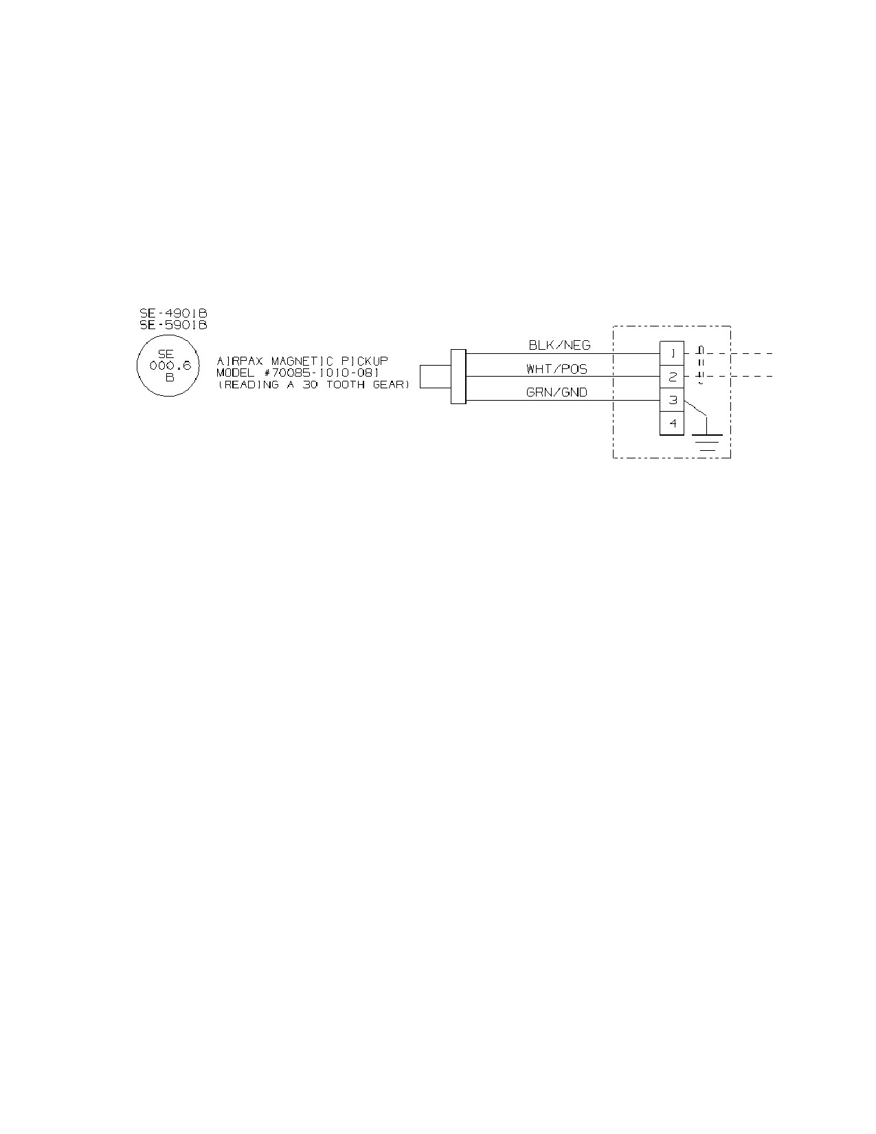
SST Turbine Instruction Manual
Low Voltage Electrical Components
terminal numbers to which the wires are terminated to are always provided on the
wire marker.
See Figure O-1 of a typical electrical schematic showing the wiring marker
information and termination methods. The wire markers are to be used from the
information in the bubbles (D-R standard tag number) as well as customer tag
numbers (located adjacent to D-R tag bubbles) if provided. Customer wiring is
shown as dotted lines.
Figure O-1 Typical Electrical Schematic Tag Numbers for Wire Marking
O.5.2
Control devices labeled
Control devices such as trip valve test pushbuttons and emergency stop buttons are
labeled with descriptive nameplates mounted on the housing of the operator
spelling out their specific function. If the customer has tag numbers, these are
included as a separate label or included in the wording of the label. See Figure O-2
for the detail of the tags indicated on the electrical schematic.
SST Turbine Instruction Manual
Revision A
259
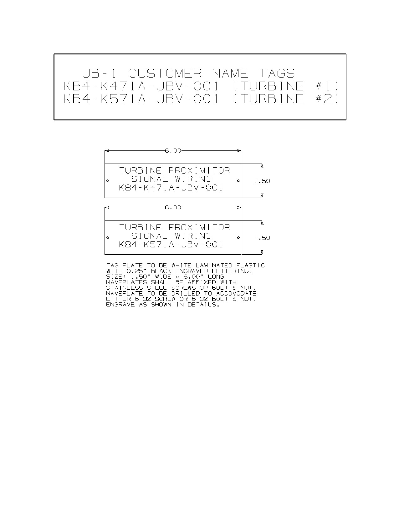
Low Voltage Electrical Components
SST Turbine Instruction Manual
Figure O-2 Typical Tag Number Labels Attached to Junction Boxes
O.5.3
As built connection boxes and wiring routing
Enclosures are supplied either to be shipped loose or are installed on the turbine
which house the vibration proximitors and temperature monitoring devices with
customer wiring termination access. The Dresser-Rand standard is for 20% spare
terminal blocks to be provided. Weidmuller SAK-4EN terminal blocks are
Dresser-Rand standard.
No splices shall be permitted in any wire of cable and no more than two wires per
terminal shall be used.
260
Revision A SST
Turbine
Instruction
SST Turbine Instruction Manual
Low Voltage Electrical Components
All wiring shall be terminated in centrally located junction boxes. Wiring in the
boxes shall be run and laced together in an orderly fashion with all nylon tie wraps
from where it leaves the conduit bushing to where it connects in the terminal box.
Here is a list of electrical components which have resistance loads and therefore
power consumptive heat can be generated. Calculations are analyzed to insure that
enclosures are selected in a large enough size to dissipate excess heat generated
from housing electrical components.
COMPONENT
WATTAGE
Peak 150 governor
38 Watts
Solenoid dump valves
36 Watts
Tachometer
15 Watts
Magnetic pickup
50 Watts
Electro-pneumatic actuator
5 Watts
TABLE O-1 WATTAGES OF ELECTRICAL COMPONENTS USED ON SST
From this table it is demonstrated that there are minimal thermal loads being added
to the overall thermal contribution from the electrical components used on SST
turbines.
O.5.4
Materials of conduit and how supported
Dresser-Rand’s standard for wiring protection is to use rigid galvanized steel
conduit supported with Unistrut installed on the baseplate, if provided. See figure
O-2 section O.5.9 for a graphic example of conduit routing on a baseplate.
All conduit runs are are to be a minimum of 10” distance from all steam lines and
steam casings, both horizontally and vertically.
Liquidtight (flex conduit) shall be used for connections to all equipment where
adjustments or vibration requires flexible connections. Maximum length of the
Liquidtight is 36”. Internal grounding wires are provided when applicable from the
device to the grounding bar installed inside the junction boxes.
O.5.5
Percentage fill of conduit
All wiring for the SST turbine does not exceed the minimum percentage fill limits
per the sizes of conduit applied.
O.5.6
Procedure to protect wiring when shipped loose
If electrical components are to be shipped loose, the wiring from the turbine to the
component will be coiled up with protective wrapping applied to the coils. The
wiring markers are installed on the wires for determination of connection to the
correct termination point per the electrical schematic and layout drawings
associated with the contract.
SST Turbine Instruction Manual
Revision A
261
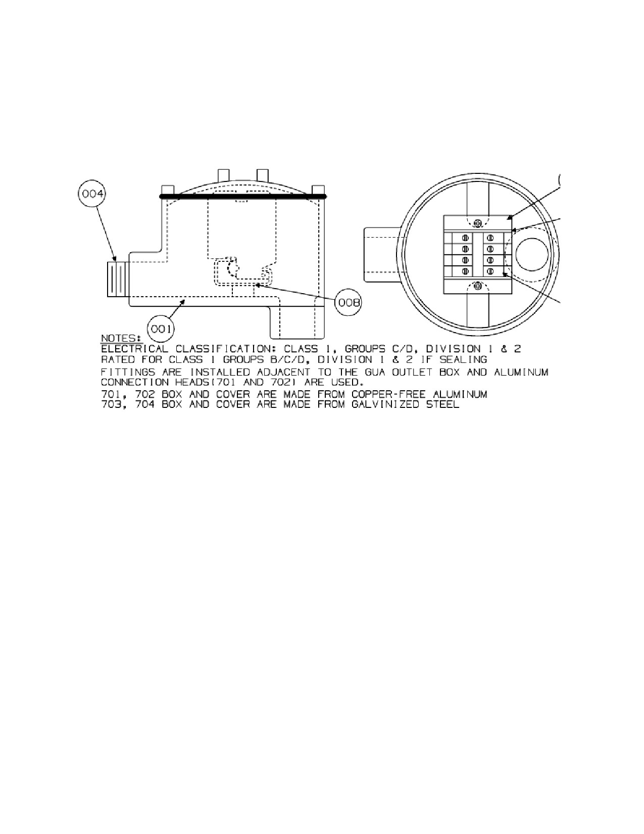
Low Voltage Electrical Components
SST Turbine Instruction Manual
O.5.7
Terminal head drawing
Figure O-3 is of a standard supplied ¾” terminal head which typically are installed
on limit switches, solenoid valves, magnetic pickups and other electrical
components which do not have their own wiring termination protective hardware.
Figure O-3 Standard ¾” Terminal Head
O.5.8
Wiring into J-box
Junction boxes shall be arranged for side or bottom entry only. Top entry is not
allowed. Conduit unions shall be provided to facilitate replacement or removal of
instruments and junction boxes.
Seals are provided for wiring entrance into all enclosures if the hazardous area
classification requires them.
Hubs are installed into the bottom of the enclosure for Dresser-Rand electrical shop
wiring entrance. Customer connections are left for field installation unless
customer requests hub installation at the factory.
Vents and drains are provided in the top and bottom of the enclosures to allow
moisture from condensation to be drained. The drains and vents are specified in
accordance with the level of protection provided with the enclosure.
262
Revision A SST
Turbine
Instruction
SST Turbine Instruction Manual
Low Voltage Electrical Components
Dresser-Rand incorporates Crouse-Hinds and Hoffmann enclosures unless there are
customer requirements for other suppliers. At a minimum the enclosures are 304
Stainless Steel with NEMA 4X ingress protection ratings.
Here is a description of the ATEX-certified (NEXT) Crouse-Hinds enclosure gasketing:
Features include thirteen basic sizes in two standard depths to optimise the
accommodation
of
rail-mountable
terminals
or
components.
Fully removable lid, concealed hinges provide 180° opening
Lid fixing, two or three stainless steel captive screws on one side
Lip on upstand increases gasket contact area, ensuring high degree of ingress protection
Internal / external earth stud
40mm wide fixing lugs for assembly on standard frames
Option of 0, 1, 2, 3 or 4 gland plates with earth stud
One piece gasket on lid and gland plates
Padlock hasp available as additional accessory
The retained stainless steel slotted hex bolt fastenings provide a rapid means of
achieving high integrity ingress protection
(IP) of
66 for reliable & rapid
environmental protection. The high integrity
“single piece” sealing gasket for
superior ingress protection
(IP) of
66 and excellent recovery and re-sealing
properties for continuous environmental protection. An integral drainage channel
prevents liquids or other solids contaminates from running in or falling into the
enclosure when the door is opened, and to minimize gasket path contamination. An
integral external & internal feed through brass earth / ground stud assembly enables
rapid and reliable protective earth / ground connection mounted on the side of the
enclosure for ease of access.
Here is a description of a Hoffmann ATEX certified enclosure:
Easy-to-use Type 316 stainless steel quarter-turn door latching
3-mm double-bit insert for security
Slot and through-hole side-mount hanging brackets
Lift-off door hinges
Fabricated from Type 316 stainless steel
Type 316 stainless steel external fasteners
Gray silicone high-temperature gasket on doors and gland plates
Internal/external brass earth/ground provision
SST Turbine Instruction Manual
Revision A
263
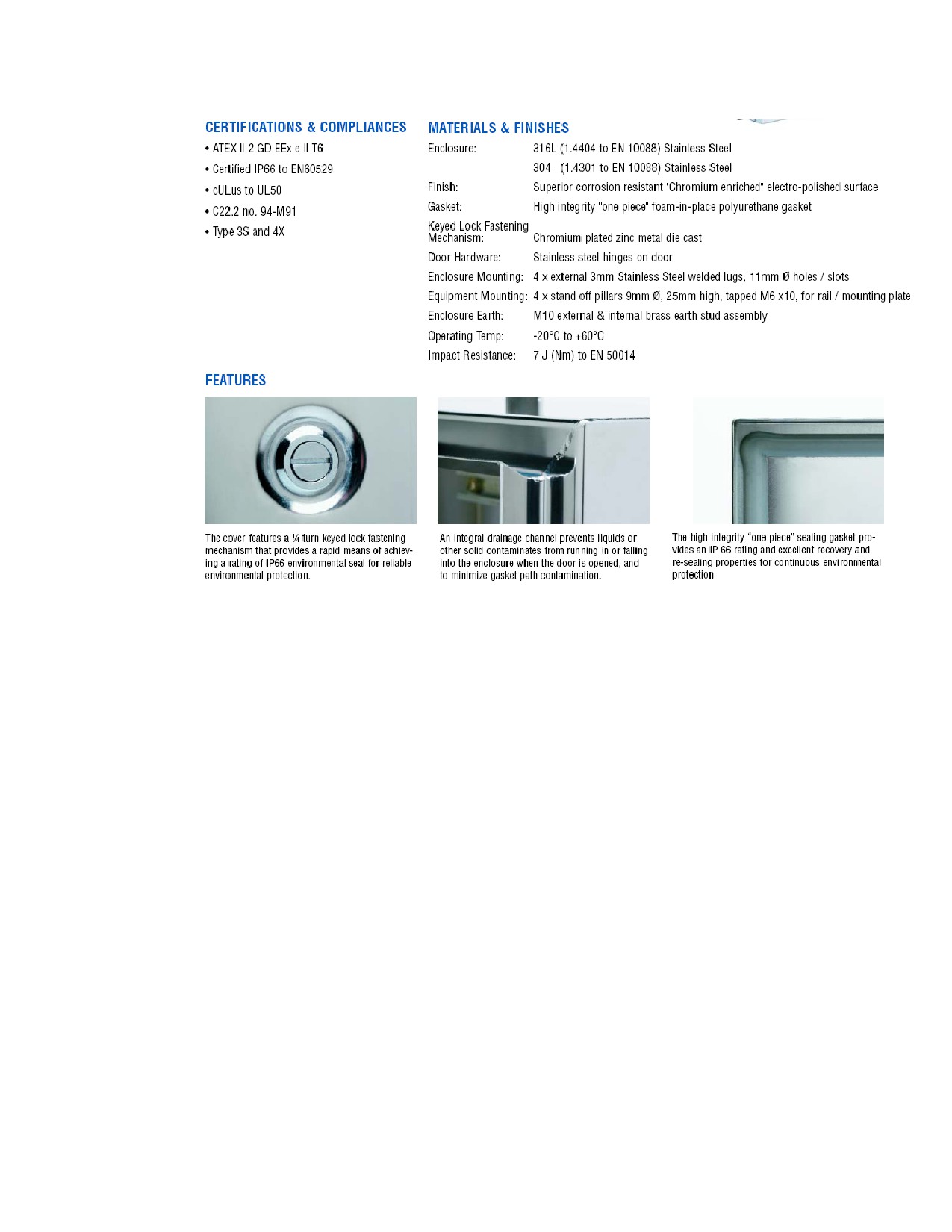
Low Voltage Electrical Components
SST Turbine Instruction Manual
FIGURE O-4 Enclosure Gasketing Details
O.5.9
Wiring routing drawing
In most cases the electrical wiring is in the customer’s scope from the magnetic
pickup termination head, the solenoid valve termination head, the limit switch
termination hardware, and the temperature monitoring device termination head. In
a few cases the turbine is sold with a baseplate and conduit runs from the
termination heads to the baseplate mounted junction boxes. Figure O-5 shows an
example of non-typical conduit routing into baseplate mounted enclosures.
264
Revision A SST
Turbine
Instruction
SST Turbine Instruction Manual
Low Voltage Electrical Components
Figure O-5 Example
of conduit routing, non-typical application
O.5.10
Details of neutral conductor
On the Dresser-Rand electrical schematic the conductor information is provided in
the notes section of the drawing.
O.5.11
Drawing stating markers for terminals and conductors
Dresser-Rand’s standard electrical schematic states the terminal type and
manufacture on the enclosure sheet of the schematic. Conductor data is located in
the notes section of the electrical schematic drawing, providing manufacture and
conductor part number data.
O.5.12
Drawing showing how cover plates are tied into bonding
SST Turbine Instruction Manual
Revision A
265
Low Voltage Electrical Components
SST Turbine Instruction Manual
On the Dresser-Rand electrical schematic/layout drawings the details of the
enclosure are provided with notes on gounding and bonding of components.
O.5.13
Drawing showing how protective bonding cross-sectional area of
circuit conductors.
Maximum impedance for protective bonding. Details of the circuit conductors are
provided in the notes section of the electrical schematics.
O.5.14
CE listed components are wired per manufacturer’s instructions.
Testing of component wiring per CENELEC EN60204-1 standards and data are
recorded on FAT form.
O.5.15
Prevention of touch voltage
Testing of touch voltage test limits per CENELEC EN60204-1 standards and data
recorded on FAT form.
O.5.16
Electrical shock hazard warning
There are electrical shock hazard warnings attached to the turbine per CENELEC EN60204-1
standards and the verification data is recorded on FAT form that all applicable drawings are
showing correct warning placement.
O.5.17 Peak starting currents and permitted voltage drops.
The electronic governors are capable of riding out minimal electrical supply
disturbances
O.5.18
Confirmation of use of SST electrical components:
A.
Temperature
Electrical components provided by Dresser-Rand are selected for use within the
environmental parameters presented by the customer. The terminal blocks,
Weidmuller SAK-4EN, have a maximum temperature rating of 100C.
B.
Altitude
Electrical components provided by Dresser-Rand are selected for use within the
environmental parameters presented by the customer. The terminal block
creepage and clearance values were calculated for 2000m above sea level.
C.
Containment
Electrical components provided by Dresser-Rand are selected for use within the
environmental parameters presented by the customer.
D.
Ionizing and non-ionizing radiation
Electrical components provided by Dresser-Rand are selected for use within the
environmental parameters presented by the customer.
E.
Vibration
266
Revision A SST
Turbine
Instruction
SST Turbine Instruction Manual
Low Voltage Electrical Components
Electrical components provided by Dresser-Rand are selected for use within the
environmental parameters presented by the customer.
F.
Shock
Electrical components provided by Dresser-Rand are selected for the use in
environmental conditions presented by the customer specifications.
G.
Physical environment
Electrical components provided by Dresser-Rand are selected for the use in
environmental conditions presented by the customer specifications.
H.
Operating conditions
Electrical components provided by Dresser-Rand are selected for the use in
operational conditions presented in the customer specifications.
I.
Voltage ride-through
Electronic governors, electronic overspeed protection, solenoid valves, limit
switches and all other electrical equipment requiring external power will revert
to shelf state in the event of disconnection from the power supply. It is the
customer responsibility to provide backup power supply capabilities if it is
imperative that the turbine stay operational at all times. The Woodward Peak
150, the most common governor used on SST machines, has a ride-through
characteristic of 28 milliseconds for the 24 VDC power source range of 18-32
VDC. Ride-through is 50 milliseconds for a 120 VDC power source range of
90-150 VDC and 4 cycles ride-trhough for 100 VAC power source range of 88-
132 VAC with a frequency range of 47-63 Hz. Input voltage fluctuations within
the acceptable ranges listed above will not affect operation of the Peak 150
control.
J.
Harmonics
The power quality of the electrical power supply is the responsibility of the
customer. It is the customer's responsibility to insure that the supplied electrical
power provided to the steam turbine is absent of power harmonics per the IEC
standards.
K.
Ingress protection
The levels of ingress protection which are spelled out in the customer
specifications will be applied in the equipment installed on the turbine.
L.
Gaskets on Enclosures
The enclosures specified by Dresser-Rand have the proper gasketing seals on the
enclosure doors to meet the customer specifications. See Figure O-4 above for
typical enclosure gasketing standards.
M. Tensile stress in cables
See Figure O-6 below for pull tension in Alpha Xtra Guard
5 cables or
equivalent typically used for wiring of RTDs and speed probes. The pull
tension of the 20 AWG is 298 N/mm2 and the pull tension of the 18 AWG wire
is 302 N/mm2 both well beyond the maximum requirements of 15 N/mm2 per
EN 60204-1:2006.
SST Turbine Instruction Manual
Revision A
267
Low Voltage Electrical Components
SST Turbine Instruction Manual
Figure O-6 Cable Pull Tension and Capacitance Properties
N.
Types of insulation and documentation Figures O-6 and O-7
O.
Heating effect on conductors
The wiring insulation provided by Dresser-Rand is certified to the highest
temperature rating available. In the notes section of the electrical schematics are
instructions to the electricians to place conduit runs at a minimum of 10” from
steam lines.
P.
Drains
It is a Dresser-Rand standard to install vertical drains on all conduit low points.
Junction box vents and drains are installed as prudent engineering practice.
Q.
Potential earth terminal leakage current
O.6
Electrical Testing
Which specific electrical testing is required for each turbine is delineated in the
Inspection and Test Plan (ITP) which is created for each turbine contract. In this
section is information pertaining to the possible tests which could be required.
268
Revision A SST
Turbine
Instruction
SST Turbine Instruction Manual
Low Voltage Electrical Components
O.6.1
Insulation test plan and certification
High potential (hipot) voltage testing with use of an insulation testing device
known as a MegOHM (meggar) resistance tester determines the condition of
insulation of the turbine wiring. Wires can be checked for good isolation between
the parts of a circuit, which helps to guarantee the safety and quality of electrical
circuits. Hipot tests are helpful in finding nicked or crushed insulation, stray wire
strands or braided shielding, conductive or corrosive contaminants around the
conductors, terminal spacing problems, and tolerance errors in IDC cables. All of
these conditions might cause a device to fail.
The Insulation Resistance test is typically done on every cable tested. It is usually
done at 300 to 500 Vdc with 100 to 500 Megahoms resistance. The test is a very
sensitive to contamination in the assembly process. Solder flux, oils, mold release
agents, and skin oil all can cause problems. This test excels at identifying insulation
that will conduct in the presence of moisture.
O.6.2
Functional preliminary testing
Each unit with an electronic governor is subjected to a Functional Acceptance Test
(FAT) . Items checked, signed and dated are:
b.
Dimensions and correct construction of the panels are checked that they conform
to the drawings.
c.
All components and instrumentation are checked for conformity.
d.
Panel hardware is checked that it conforms to drawings.
e.
All AC and DC power inputs are checked for shorts and isolation between
circuits and grounds
f.
Panel is checked for internal grounding circuits.
g.
Circuit breakers are closed and checked for governor and interface wiring.
h.
All AC and DC power inputs to the panel are checked with proper voltage
supplies.
i.
Electronic governor program is checked for accuracy.
j.
All alarm inputs to panels are simulated for proper indication .
k.
All trip modes in control system are simulated for proper indication on panel.
Trip signals are verified.
l.
The balance of control loops are simulated, checking for correct operation,
indication, and outputs.
m. All circuits are checked for continuity.
O.6.3
Functional bonding test data
Testing of bonding per CENELEC EN60204-1 standards and data recorded on FAT
form.
O.6.4
High leakage current test limits and terminal leakage current
SST Turbine Instruction Manual
Revision A
269
Low Voltage Electrical Components
SST Turbine Instruction Manual
Testing of high leakage current test limits per CENELEC EN60204-1 standards
and data recorded on FAT form.
O.6.5
Analysis and test report documents showing barrier protection
Testing of barrier protection per CENELEC EN60204-1 standards and data
recorded on FAT form.
O.6.6
Documentation on insulation of Wire and Terminal Blocks
Testing of insulation current test limits per CENELEC EN60204-1 standards and
data recorded on FAT form.
Here are some of the details of the Alpha wire which is a standard Dresser-Rand
component. Bend radius is 10X cable diameter, pull tension is 56 pounds
maximum, voltage rating is 300 Volts RMS, capacitance is 26 picofarads per foot
at 1 kHz nominal, ground capacitance is 47 picofarads per foot at 1 kHz nominal.
Inductance is 0.16 micro henries per foot nominal, conductor DCR is 6.4 ohms per
1000 feet at 20 degrees C, nominal, OA shield DCR is 4.5 ohms per 1000 feet at
20 degrees C.
The maximum and minimum temperature rating range of the typically used Alpha
wire is from -80 to 200C. This wiring is used for the actuator, magnetic speed
probes and RTD temperature monitoring and very infrequently is located within
conduit runs which are near the bearing cases and actuator. The steam chest is
typically jacketed with a thermal insulation barrier for protection of surrounding
equipment and personnel. In most cases the customer is providing the wiring to the
actuator terminal head as well as the RTD and magnetic speed probe termination
heads installed on the bearing cases. The temperature levels are much lower than
the inlet temperatures in proximity to the bearing cases.
O.6.7
Documentation showing no residual voltage
Testing of residual voltage test limits per CENELEC EN60204-1 standards and
data recorded on FAT form.
O.6.8
Documentation showing size and location of terminal points, all wire
is copper, PE connections
Dresser-Rand standard electrical schematics show the size and location of terminal
points as well as wire type and manufacture and PE connections.
O.6.9
Test report on SST conductor clearances with each other.
Testing of conductor clearances per CENELEC EN60204-1 standards and data
recorded on FAT form. The values for the conductor clearances and creepage were
calculated from an Extract DIN VDE 0110-04.97. This standard is a technical
adaptation of IEC Report 664/664A. Installation Category II was used, which is
270
Revision A SST
Turbine
Instruction
SST Turbine Instruction Manual
Low Voltage Electrical Components
for equipment intended for use in installations or parts of installations in which no
overvoltages can occur.The clearance calculations were conducted per the
dimensions and characteristics of the Weidmuller SAK-4EN terminal blocks which
are standard offering of D-R. The clearance calculations indicate a maximum of
1.2 mm for these terminal blocks. The clearance between the terminals of the
SAK-4EN terminal blocks is 6.5 mm, more than 5 times the minimum clearance
allowed.
O.6.10
Test report on SST creepage of Conductors
Testing of creepage per CENELEC EN60204-1 standards and data recorded on
FAT form. The creepage calculations were checked per the Weidmuller SAK-4EN
terminal block dimensions. The distances between the conductors minimum
calculated value due to creepage is 1.5 mm which is 1/5 of the 6.5 mm terminal
block distances being used.
O.6.11
Test report on SST mechanical damage caused by short circuits.
Testing of short circuit test limits per CENELEC EN60204-1 standards and data
recorded on FAT form.
O.6.13
Analysis on SST enclosure gasketing construction.
Dresser-Rand incorporates Crouse-Hinds and Hoffmann enclosures unless there are
customer requirements for other suppliers. At a minimum the enclosures are 304
Stainless Steel with NEMA 4X ingress protection ratings.
O.7
Programming of Electrical Devices
O.7.1
Peak 150 programmer and program entry
In the Woodward Peak 150 Installation and Operation manual 85565 complete and
thorough instructions are provided for the programming of the Peak 150 governor.
Dresser-Rand provides a governor program which has the values that are punched
into the governor via the supplied hand held programmer.
O.7.2
Tachometer program entry
A.
Tachtrol 30
For each turbine which has a AI-Tek tachometer, D-R provides programming
parameters on the associated electrical schematic drawing.
B.
Moore
C.
Red Lion
For each turbine which has a Red Lion speed meter, D-R provides
programming parameters on the associated electrical schematic drawing.
SST Turbine Instruction Manual
Revision A
271
Low Voltage Electrical Components
SST Turbine Instruction Manual
D.
Beka
For each turbine which has a Beka tachometer, D-R provides programming
parameters on the associated electrical schematic drawing.
O.7.3
Valtek Calibration
The electro-pneumatic actuators are calibrated at the Dresser-Rand factory before the
no-load testing of each unit.
O.8
Customer Responsibilities
O.8.1
Power supply disconnect method
Typically the customer is responsible for the design and installation of power
supply disconnect hardware for the electronic governor, electronic over-speed
protection, solenoid valves and other power consuming components mounted on
the turbine. There must be an acceptable disconnect (isolation) at each single
incoming source when required (for example: for work on the machine, including
electrical equipment). When two or more supply disconnecting devices are
provided, protective interlocks for their correct operation shall also be provided in
order to prevent a hazardous situation, including damage to the machine or to the
work in progress.
The supply disconnecting device shall be one of the following types:
A. Switch-disconnector, with or without fuses, in accordance with IEC 60947-3,
utilization category AC-23B or DC-23B
B. Disconnector, with or without fuses, in accordance with IEC 60947-3, that has
an auxiliary contact that in all cases causes the switching devices to break the
load circuit before the opening of the main contacts of the disconnector.
C. A circuit breaker suitable for isolation in accordance with IEC 60947-2
D. Any other switching device in accordance with an IEC product standard for that
device and which meets the isolation requirements of IEC 60947-1 as well as a
utilization category defined in the product standard as appropriate for on-load
switching of motors or other inductive loads
E. A plug/socket combination for a flexible cable supply.
When the supply disconnecting device is one of the types listed in the above
sections A to D, it shall fulfill all of the following requirements:
a)
Isolate the electrical equipment from the supply and have one OFF (isolated) and one
ON position marked with “O” and “I”
(symbols IEC 604178-5008 (DB:2002-10) and
IEC 60417-5007 (DB:2002-10)).
272
Revision A SST
Turbine
Instruction
SST Turbine Instruction Manual
Low Voltage Electrical Components
b)
Have a visible contact gap or a position indicator which cannot indicate OFF (isolated)
until all contacts are actually open and the requirements for the isolating function have
been satisfied.
c)
Have an external operating means (for example—handle), (exception: power-operated
switchgear need not be operable from outside the enclosure where there are other means
to open it). Where the external operating means is not intended for emergency
operations, it is recommended that it be colored BLACK or GRAY.
d)
To be provided with a means permitting it to be locked in the OFF (isolated) position
(for example by padlocks). When so locked, remote as well as local closing shall be
prevented.
e)
Disconnect all live conductors of its power supply circuits. However, for TN supply
systems, the neutral conductor may or may not be disconnected except in countries
where disconnection of the neutral conductor (when used) is compulsory.
f)
Have breaking capacity sufficient to interrupt the current of the largest motor when
stalled together with the sum of the normal running currents of all other motors and/or
loads. The calculated breaking capacity may be reduced by the use of a proven
diversity factor.
When the supply disconnecting device is a plug/socket combination, it shall fulfill
the following requirements:
Have the switching capability, or be interlocked with a switching device that has a
breaking capacity sufficient to interrupt the current of the largest motor when
stalled together with the sum of the normal running currents of all other motors
and/or loads. The calculated breaking capacity may be reduced by the use of a
proven diversity factor. When the interlocked switching device is electrically
operated (for example: a contactor) it shall have an appropriate utilization category.
Where the supply disconnecting device is a plug/socket combination, a switching
device with at appropriate utilization category shall be provided for switching the
machine on and off. This can be achieved by the use of the interlocked switching
device described above.
Operating Means—
The operating means (for example, a handle) of the supply disconnecting device
shall be easily accessible and located between 0.6 m (1.9 ft.) and 1.9 m (6.2 ft.)
above the servicing level. An upper limit of 1.7 (5.6 ft.) is recommended.
SST Turbine Instruction Manual
Revision A
273
Low Voltage Electrical Components
SST Turbine Instruction Manual
Excepted Circuits—
The following circuits need not be disconnected by the supply disconnecting
device:
a)
Under-voltage protection circuits that are only provided for automatic tripping
in the event of supply failure.
b)
Where such a circuit is not disconnected by the supply disconnecting device:
permanent wiring label(s) in accordance with 16.1 shall be appropriately placed in
proximity to the supply disconnecting device.
Local operation of the supply disconnecting device to effect emergency switching
off shall be readily accessible and should meet the color requirements.
O.8.2
Customer responsibility for emergency stop controls and devices,
location description of emergency devices
It is the customer’s responsibility to provide emergency stop controls and devices
and provide the location description and accessibility of these emergency devices.
Combined start and stop controls. Push-buttons and similar control devices that,
when operated, alternately initiate and stop motion shall only be provided for
functions which cannot result in a hazardous situation.
Use of more than one operator control station. Where a machine has more than one
operator control station, including one or more cable-less control stations, measures
shall be provided to ensure that only one of the control stations can be enabled at a
given time. An indication of which operator control station is in control of the
machine shall be provided at suitable locations as determined by the risk
assessment of the machine.
Devices for emergency stop shall be readily accessible by being located at each
operator control stations and at other locations where the initiation of an emergency
stop can be required.
There can be circumstances where confusion can occur between active and inactive
emergency stop devices caused by disabling the operator control station. In such
cases, means (for example: information for use) shall be provided to minimize
confusion.
Emergency switching off devices shall be located as necessary for the given
application. Normally, those devices will be located separate from operator control
stations. Where it is necessary to provide a control station with an emergency stop
device and an emergency switching off device, means shall be provided to avoid
confusion between these devices.
274
Revision A SST
Turbine
Instruction
SST Turbine Instruction Manual
Low Voltage Electrical Components
Color of actuators. Actuators of emergency switching off devices shall be colored
RED. If a background exists immediately around the actuator, the background
shall be colored YELLOW.
O.8.3
Customer responsibility for earth faults - required accidental start
protection
The customer is responsibility to provide earth fault interrupt equipment and
lockout process and procedure to prevent accidental startup.
Earth faults on any control circuit shall not cause unintentional starting, potentially
hazardous motions, or prevent stopping of the machine.
O.8.4
Customer responsibility for potentiometer rotation stop
The customer is responsible for providing rotation stops on any and all
potentiometer installations.
Devices having a rotational member, such as potentiometers and selector switches,
shall have the means of prevention of rotation of the stationary member. Friction
alone shall not be considered sufficient.
O.8.5
Customer responsibility for stopping by de-energizing
The customer is required to institute controls which will facilitate the turbine
stopping by de-energizing the controls.
O.8.6
Customer responsibility that control circuits are connected to bonding
circuit
The customer is responsible for ensuring the control circuits are connected to the
bonding circuit which is also within the customer’s responsibility.
Protection by automatic disconnection of supply: This measure consists of the
interruption of one or more of the line conductors by the automatic operation of a
protective device in case of a fault. This interruption shall occur within a
sufficiently short time to limit the duration of a touch voltage to a time within
which the touch voltage is not hazardous.
These measures necessitate the coordination between:
a) The type of supply and earthing system.
b) The impedance values of the different elements of the protective bonding
system
c) The characteristics of the protective devices that detect insulation fault(s).
Automatic disconnection of the supply of any circuit affected by an insulation
fault is intended to prevent a hazardous situation resulting from a touch voltage.
SST Turbine Instruction Manual
Revision A
275
Low Voltage Electrical Components
SST Turbine Instruction Manual
This protective measure comprises both protective bonding of exposed conductive
parts and either:
a) Over-current protective devices for the automatic disconnection of the supply
on detection of an insulation fault in TN systems, or
b) Residual current protective devices to initiate the automatic disconnection of
the supply on detection of an insulation fault from a live part to exposed
conductive parts or to earth in TT systems, or
c) Insulation monitoring or residual current protective devices to initiate automatic
disconnection of IT systems. Except where a protective device is provided to
interrupt the supply in the case of the first earth fault, an insulation monitoring
device shall be provided to indicate the occurrence of a first fault from a live
part to exposed conductive parts or to earth. This insulation monitoring device
shall initiate an audible and/or visual signal which shall continue as long as the
fault persists.
O.8.7
Customer responsibility that battery control station will not cause
hazardous condition
The customer has the responsibility to insure that the battery control station will not
cause any hazardous condition to exist in the SST operation.
Battery-powered operator control stations. A variation in the battery voltage shall
not cause a hazardous situation. If one or more potentially hazardous motions are
controlled using a battery-powered cable-less operator control station, a clear
warning shall be given to the operator when a variation in battery voltage exceeds
specified limits. Under those circumstances, the cableless operator control station
shall remain functional long enough for the operator to put the machine into a non-
hazardous situation.
O.8.8
Customer responsibility for operator control station stop over-ride
precedence
The customer is responsible for instituting the hardware/software to guarantee
operator control station stop over-ride precedence.
O.8.9
Customer responsibility for enabling control requirements
The customer is responsible for enabling control requirements.
Start functions. Start functions shall operate by energizing the relevant circuit.
Enabling control is a manually activated control function interlock that:
a) When activated allows machine operation to be initiated by a separate start
control
276
Revision A SST
Turbine
Instruction
SST Turbine Instruction Manual
Low Voltage Electrical Components
b) When de-activated---
---initiates a stop function and----prevents initiation of machine
operation.
Enabling control shall be so arranged as to minimize the possibility of defeating the
shut-down command, for example: by requiring the de-activation of the enabling
control device before machine operation may be re-initiated. It should not be
possible to defeat the enabling function by simple means.
O.8.10
Customer responsibility that ES (Emergency Stop) shuts off motive
force
The customer is responsible for proper design of the emergency stop controls
which will shut off any and all of the motive force to the turbine.
Emergency stop operations (emergency stop, emergency switching off). Once
active operation of emergency stop or emergency switching off of the actuator has
ceased following a command, the effect of this command shall be sustained until it
is reset. This reset shall be possible only by manual action at that location where
the command has been initiated. The reset of the command shall not restart the
machinery but only permit restarting.
O.8.11
Customer responsibility that resetting of ES requires manual
intervention
The customer has the responsibility to properly incorporate into the turbine controls
that the resetting of the emergency stop components requires manual intervention
for the reset of the turbine controls.
The emergency stop shall function either as a stop category 0 or as a stop category
1. The choice of the stop category of the emergency stop depends on the results of
a risk assessment of the machine.
In addition to the requirements for stop, the emergency stop function has the
following requirements:
a) It shall override all other functions and operations in all modes.
b) Power to machine actuators that can cause a hazardous situation(s) shall be
either removed immediately (stop category 0) or shall be controlled in such a
way to stop the hazardous motion as quickly as possible (stop category 1)
without creating other hazards.
c) Reset shall not initiate a start
SST Turbine Instruction Manual
Revision A
277
Low Voltage Electrical Components
SST Turbine Instruction Manual
O.8.12
Customer responsbility that any stop function over-rides any start
function
The customer has the responsibility to design and incorporate into the controls the
capability of any and all stop functions to over-ride any and all of the start function
controls.
Stop Function.
a) Stop category 1: A controlled stop with power available to the machine
actuators to achieve the stop and the removal of power when the stop is
achieved.
b) Stop category 2: A controlled stop with power left available to the machine
actuators.
Where more than one control station is provided, stop commands from any control
station shall be effective when required by the risk assessment of the machine.
O.8.13
Customer responsibility to provide over-current protection
It is the customer’s responsibility to properly design, install, and maintain over-
current protection equipment. The measures to be taken to protect the equipment
against the effects of over-current arising are from a short circuit, abnormal
temperature, loss of or reduction in the supply voltage, earth fault/residual current,
and over-voltage due to lighting and switching surges. General over-current
protection shall be provided where the current in a machine circuit can exceed
either the rating of any component of the current carrying capacity of the
conductors, whichever is the lesser value.
Supply conductors. Unless otherwise specified by the user, the supplier of the
electrical equipment is not responsible for providing the over current protective
device for the supply conductors to the electrical equipment Dresser-Rand states on
the P&I list the data necessary for selecting the over current protective device.
Power circuits. Devices for detection and interruption of over current shall be
applied to each live conductor.
The following conductors, as applicable, shall not be disconnected without
disconnecting all associated live conductors:
a) Neutral conductor of AC power circuits
b) The earthed conductor of DC power circuits
c) DC power conductors bonded to exposed conductive parts of mobile machines
Control circuits. Conductors of control circuits directly connected to the supply
voltage and of circuits supplying control circuit transformers shall be protected
278
Revision A SST
Turbine
Instruction
SST Turbine Instruction Manual
Low Voltage Electrical Components
against over-current. Conductors of control circuits supplied by a control circuit
transformer or DC supply shall be protected against over-current:
a) In control circuits connected to the protective bonding circuit, by inserting an
over-current protective device into the switched conductor.
b) In control circuits not connected to the protective bonding circuit.
c) Where the same cross sectional area conductors are used in all control circuits,
by inserting an over-current protective device into the switched conductor.
d) Where different cross-sectional areas conductors are used in different sub-
circuits, by inserting an over-current protective device into both switched and
common conductors of each sub-circuit.
Lighting circuits. All unearthed conductors of circuits supplying lighting shall be
protected against the effects of short circuits by the provision of over-current
devices separate from those protecting other circuits.
O.8.14
Customer responsibility that start functions shall operate by
energizing relevant circuit
The customer’s responsibility is to insure that the start functions shall operate by
energizing the specific circuit which starts the turbine.
In the case of machines requiring the use of more than one control station to initiate
a start, each of these control stations shall have a separate manually actuated start
control device. The conditions to initiate a start shall be:
a) All required conditions for machine operation shall be met.
b) All start control devices shall be in the released (off) position.
c) All start control devices shall be actuated concurrently.
O.8.15
Customer is responsible for DC power supplies
The customer is responsible for the proper sizing, installation and maintenance of
DC power supplies.
O.8.16
Customer is responsible for protective bonding circuit
The customer is responsible for the proper installation and maintenance of
protective bonding circuitry.
Dresser-Rand, when the contract requires it, provides bonding/grounding lugs on
the sole-plates, gauge-boards, and base-plates as shown in figures O-7 through O-9.
SST Turbine Instruction Manual
Revision A
279
Low Voltage Electrical Components
SST Turbine Instruction Manual
Figure O-7 Location of grounding lug (021) on turbine baseplate
280
Revision A SST
Turbine
Instruction
SST Turbine Instruction Manual
Low Voltage Electrical Components
Figure O-8 Grounding lug (008) on gaugeboard
Figure O-9 Grounding lug (007) on soleplate
Equi-potential bonding. Normally functional grounding is achieved by connection
to the protective bonding circuit. But where the level of electrical disturbances on
the protective bonding circuit is not sufficiently low for proper functioning of
electrical equipment, it may be necessary to connect the functional bonding circuit
to a separate functional earthing conductor.
Protective bonding circuit. The protective bonding circuit consists of PE
terminal(s). All parts of the protective bonding circuit shall be so designed that
they are capable of withstanding the highest thermal and mechanical stresses that
can be caused by the earth-fault currents that could flow in that part of the
protective bonding circuit. Where the conductance of structural parts of the
electrical equipment or of the machine is less than that of the smallest protective
conductor connected to the exposed conductive parts, a supplementary bonding
conductor shall be provided. This supplementary bonding conductor shall have a
cross-sectional area not less than half that of the corresponding protective
conductor.
SST Turbine Instruction Manual
Revision A
281
Low Voltage Electrical Components
SST Turbine Instruction Manual
If an IT distribution system is used, the machine structure shall be part of the
protective bonding cirduit and insulation monitoring shall be provided.
Protective conductors. Copper conductors are preferred. Where a conductor
material other than copper is used, its electrical resistance per unit length shall not
exceed that of allowable copper conductor and such conductors shall be not less
than 16 square mm in cross-sectional area.
The cross-sectional area of protective conductors. This requirement is met in most
cases where the relationship between the cross-sectional area of the phase
conductors associated with that part of the equipment and the cross-sectional area
of the associated protective conductor is in accordance with Table 1.
Continuity of the protective bonding circuit. All exposed conductive parts shall be
connected to the protective bonding circuit.
Exclusion of switching devices from the protective bonding circuit. The protective
bonding circuit shall not incorporate a switching device or an over-current
protective device (for example, switch or fuse). No means of interruption of the
protective grounding conductor shall be provided. Exception: Links for test or
measurement purposes that cannot be opened without the use of a tool and that are
located in an enclosed electrical operating area. Where the continuity of the
protective bonding circuit can be interrupted by means of removable current
collectors or plug/socket combinations, the protective bonding circuit shall be
interrupted by a first-make last-break contact.
Protective conductor connecting points. The protective conductor connecting
points shall have no other function and are not intended, for example, to attach or
connect appliances or parts. Each protective conductor connecting point shall be
marked or labeled as such using the symbol IEC 60417-5019 (DB:2002-10), or
with letters PE, the graphical symbol being preferred, or by use of the bi-color
combination GREEN-AND-YELLOW, or any combination of these.
Functional bonding. Protection against mal-operation as a result of insulation
failures can be achieved by connecting to a common conductor.
Measures to limit effects of high leakage current. The effects of high leakage
current can be restricted to the equipment having high leakage current by
connection of that equipment to a dedicated supply transformer having separate
windings. The protective bonding circuit shall be connected to exposed conductive
parts of the equipment and, in addition, to the secondary winding of the
transformer.
282
Revision A SST
Turbine
Instruction
SST Turbine Instruction Manual
Low Voltage Electrical Components
Control circuits supply. Where control circuits are supplied from an AC source, a
control transformer shall be used for supplying the control circuits. Such
transformer shall have separate windings.
Where DC control circuits derived from an AC supply are connected to the
protective bonding circuit, they shall be supplied from a separate winding of the
AC control circuit transformer or by another control circuit transformer.
O.8.17
Customer is responsible for over-voltage suppression
(lightning
arrestors)
The customer is responsible for the proper installation and maintenance of over-
voltage surge protection (lightning arrestors).
Protection against over-voltages due to lightning and to switching surges.
Protective devices can be provided to protect against effects of over-voltages due to
lightning or to switching surges where provided:
a)
Devices for the suppression of over-voltages due to lightning shall be
connected to the incoming terminals of the supply disconnecting device.
b)
Devices for the suppression of over-voltages due to switching surges shall be
connected across the terminals of all equipment requiring such protection.
O.8.18
Customer is responsible for transformer over-current protection.
The customer is responsible for all transformer over-current protection devices to
be installed properly and maintained.
Transformers shall be protected against over-current in accordance with the
manufacturer instructions. Such protection shall also avoid nuisance tripping due
to transformer magnetizing inrush currents. The type and setting of the over-
current protective device should be in accordance with the recommendations of the
transformer supplier.
O.8.19
Customer is responsible for certifications
The customer is responsible for maintaining the certification documentation
required for customer ATEX/EU compliance.
O.8.20
Customer is responsible for accidental disabling of electricity to
SST turbine
The customer is responsible for proper design and installation of equipment to
prevent accidental power interruption to the SST turbine.
Protection against supply interruption or voltage reduction and subsequent
restoration. These conditions can cause a hazardous situation, damage to the
SST Turbine Instruction Manual
Revision A
283
Low Voltage Electrical Components
SST Turbine Instruction Manual
machine or to work in progress. Under-voltage protection shall be provided by, for
example, switching off the machine at a pre-determined voltage level. Upon
restoration of the voltage or upon switching on the incoming supply, automatic or
unexpected restarting of the machine shall be prevented where such a restart can
cause a hazardous situation.
O.8.21
Customer is responsible for prevention of unwanted startup
It is the customer’s responsibility to design, install, and incorporate lockout
hardware and procedures to prevent unwanted turbine startup.
Devices for switching off for the prevention of unexpected startup (for example:
where, during maintenance, a start-up of the machine or part of the machine can
create a hazard).
Such device shall be appropriate and convenient for the intended use, shall be
suitable placed, and readily identifiable as to their function and purpose
(for
example: by a durable marking in accordance with 16.1 where necessary).
Means shall be provided to prevent inadvertent and/or mistaken closure of these
devices either at the controller or from other locations. Devices that do not fulfil
the isolation function (for example, a contactor switched off by a control circuit)
may only be provided where intended to be used for situations that include:
a) Inspections
b) Adjustment
O.8.22
Customer is responsible for locking of emergency off isolation
operators
It is the customer’s responsibility to incorporate locking out of emergency shut-
down isolator hardware.
Emergency switching off should be provided where there is the possibility of other
hazards or damage caused by electricity.
Emergency switching off is accomplished by switching off the relevant incoming
supply by electromechanical switching devices, effecting a stop category 0 of
machine actuators connected to this incoming supply. When a machine cannot
tolerate this stop category 0 stop, it may be necessary to provide other measures,
for example: protection against direct contact, so that emergency switching off is
not necessary.
O.8.23
It is the customer responsibility to ensure that there is not a
connection between the neutral conductor and the protective bonding
circuit
284
Revision A SST
Turbine
Instruction
SST Turbine Instruction Manual
Low Voltage Electrical Components
According to CENELEC EN60204-1 it is the customer responsibility to insure that
there is not a connection between the neutral conductor and the protective bonding
circuit.
There shall be no connection between the neutral conductor and the protective
bonding circuit inside the electrical equipment nor shall a combined PEN terminal
be provided. Exception: a connection may be made between neutral terminal and
the PE terminal at the point of the connection of the power supply to the machine
for TN-C systems.
O.8.24
It is the customer responsibility to guarantee that the electrical
components on the SST turbine are connected to a single incoming
power source.
A single point connection for the turbine power must be provided by the customer
that meets the parameters outlined in this chapter.
Incoming supply conductor terminations: It is recommended that, where
practicable, the electrical equipment of a machine is connected to a single incoming
supply. Where another supply is necessary for certain parts of the equipment (for
example, electronic equipment that operates at a different voltage), that supply
should be derived, as far as is practicable, from devices (for example, transformers,
converters) forming part of the electrical equipment of the machine.
O.8.25
Power supply testing is the responsibility of the customer.
The customer is responsible for the power supply testing per the requirements of
CENELEC EN60204-1.
The connection of the power supply and of the incoming external protective
conductor the the PE terminal of the machine, shall be verified by inspection. The
conditions for the protection by automatic disconnection of supply shall be verified
by both:
1) Verification of the fault loop impedance by
a) Calculation
b) Measurement
2) Confirmation that the setting and characteristics of the associated over-current
protective device are correct.
Functional tests. The function of electrical equipment shall be tested. The function
of circuit for electrical safety (for example: earth fault detection) shall be tested by
the manufacturer.
SST Turbine Instruction Manual
Revision A
285
Low Voltage Electrical Components
SST Turbine Instruction Manual
Re-testing. Where a portion of the machine and its associated equipment is
changed or modified, that portion shall be re-verified and re-tested as appropriate.
This re-testing is the responsibility of the customer.
O.8.26
Power quality customer requirements.
The customer is required by the IEC low voltage directive EN60204-1 to provide
power to the electrical load of supplied devices with harmonic distortion not
exceeding 10% of the total r.m.s. voltage between live conductors for the sum of
the 2nd through to the 5th harmonic. An additional 2% of the total r.m.s. voltage
between live conductors for the sum of the 6th through to the 30th harmonic is
permissible.
O.8.27
Customer responsibility for protection from electric shock.
The customer is responsible for the wiring and connection of electrical components
and equipment of electrical components which is in their scope (any wiring and
installation of equipment not installed and wired by Dresser-Rand) per the
component manufacturer instructions.
The electrical equipment shall provide protection of persons against electric shock
from:
a) Direct contact
b) Indirect contact
O.8.28
Customer responsible for abnormal temperature protection.
Resistance heating or other circuits that are capable of attaining or causing
abnormal temperatures (for example, due to short-time rating or loss of cooling
medium) and therefore can cause a hazardous situation shall be provided with
suitable detection to initiate an appropriate control response.
O.8.29
Customer responsible for motor over-speed protection.
The over-speed protection of auxiliary motors, such as lube oil pump motors,
which are in the customers’ scope of supply, are the responsibility of the customer
to provide over-speed protection controls.
O.8.30
Customer responsibility for operation and minimizing risks.
Where a machine has more than one control station, measures shall be provided to
ensure that the initiation of commands from different control stations do not lead to
a hazardous situation.
Control functions in the event of failure. Where failures or disturbances in the
electrical equipment can cause a hazardous situation or damage to the machine or
to the work in progress, appropriate measures shall be taken to minimize the
probability of the occurrence of such failures or disturbances. The required
286
Revision A SST
Turbine
Instruction
SST Turbine Instruction Manual
Low Voltage Electrical Components
measures and the extent to which they are implemented, either individually or in
combination, depend on the level of risk associated with the respective application.
The electrical control circuits shall have an appropriate level of safety performance
that has been determined from the risk assessment at the machine. The
requirements of IEC 60261 and/or 13849-1:1999, ISO 13849-2:2003 shall apply.
Measures to reduce those risks include but are not limited to:
a) Use of proven circuit techniques and components
b) Provision of partial or complete redundancy or diversity
c) Provision for functional tests
Measures to minimize risk in the event of failure - Use of proven circuit techniques
and components.
These measures include but are not limited to:
a) Bonding of control circuits to the protective bonding circuit for functional
purposes.
b) Connection of control devices 1
c) Stopping by de-energizing
d) Switching devices having direct opening action (see IEC 60947-5-1)
O.8.31
Physical separation or grouping (11.2.2) customer responsibility.
Control devices mounted in the same location and connected to the supply voltage,
or to both supply and control voltages, shall be grouped separately from those
connected only to the control voltages.
Terminals shall be separated into groups for:
a) Power circuits
b) Associated control circuits
c) Other control circuits, fed from external sources (for example: for interlocking)
The groups may be mounted adjacently, provided that each group can be readily
identified
(for example: by markings, by the use of different sizes, by use of
barriers or by colors). When arranging the location of devices
(including
interconnections), the clearances and creepage distances specified for them by the
supplier shall be maintained, taking into account the external influences or
conditions of the physical environment.
O.8.32
Customer responsibility for prevention of indirect contact
SST Turbine Instruction Manual
Revision A
287
Low Voltage Electrical Components
SST Turbine Instruction Manual
For each circuit or part of the electrical equipment, at least one of the measures
shall be applied:
a) Measure to prevent the occurrence of a touch voltage or
b) Automatic disconnection or the supply before the time of contact with a touch
voltage can become hazardous
Prevention of the occurrence of a touch voltage. Measures to prevent the
occurrence of a touch voltage include the following:
a) Provision of class II equipment by equipment insulation
b) Electrical separation
Protection by provision of class II equipment or by equivalent insulation. This
measure is intended to prevent the occurrence of touch voltage on the accessible
parts through a fault in the basic insulation. This protection is covered by one of
the following:
a) Class II electrical devices or apparatus (double insulation, reinforced insulation
or by equivalent insulation in accordance with IEC 61140)
b) Switch-gear and control-gear assemblies having total insulation in accordance
with IEC 60439-1
c) Supplementary or reinforced insulation in accordance with 413.2 of IEC 60364-
4-41
Protection by electrical separation of an individual circuit is intended to prevent a
touch voltage through contact with exposed conductive parts that can be energized
by a fault in the basic insulation of the live parts of that circuit. For this type of
protection, the requirements of 413.3.5 of IEC 60364-4-41 apply.
288
Revision A SST
Turbine
Instruction