Dresser-Rand. Instruction Manual for Single Stage 350, 500, and 700 Frame Steam Turbines (2011) - page 1
Table of Contents
SST Turbine Instruction Manual
Table of Contents
How to Use This Manual
1
EU Compliance
3
Table of Contents
4
List of Figures
13
List of Tables
15
Safety Precautions
17
Section A Introduction and General Description
25
A.1
Turbine Description
25
A.2
Construction
25
A.3
Main Components
27
A.4
Factory Test
36
A.5
Shipping Preparation/Crating
37
A.6
Uncrating and Inspection
37
A.7
Short-term Storage
38
A.8
Long-term Storage
39
A.9
Dresser-Rand Factory Service/Replacement Parts
41
A.10
Re-Rating and Upgrades
42
A.11
Nameplate Information
43
Section B Technical Data
45
B.1
General
45
B.2
Lifting
45
B.3
Alignment
46
B.4
Thermal Growth
47
B.5
Lubricants
48
4
Revision A SST
Turbine
Instruction
SST Turbine Instruction Manual
Table of Contents
B.6
Major Fits, Clearances, and Rotor Balance Criteria
49
B.7
Piping Forces
56
B.8
Bolt Torques and Materials
57
B.9
Sealants and Joint Compounds
58
B.10
Cooling Water to Bearing Housing Water Jackets
60
B.11
Steam Pressure and Temperature Limits
60
B.12
Steam Quality and Steam Purity
60
B.13
Turbine Rotor Data
62
Section C Installation
63
C.1
General
63
C.2
Foundation
65
C.3
Piping
67
C.3.1
Piping Forces
68
C.3.2
Isolating Valves
69
C.3.3
Full Flow Relief Valve
70
C.3.4
Inlet Piping
71
C.3.5
Exhaust Piping
72
C.3.6
Piping Blow Down
73
C.3.7
Steam Strainer
73
C.3.8
Check Valve
74
C.3.9
Expansion Joints
74
C.3.10
Leak-Off Piping
77
C.3.11
Gland Seal Leak-Off Piping - Vacuum Exhaust
78
C.3.12
Gland Seal Intermediate Leak-Off Piping - High Back Pressure Exhaust
78
C.3.13
Drain Piping
81
C.3.14
Water Cooling Piping to Bearing Housing Water Jackets
82
C.4
Alignment Requirements
84
C.5
Couplings
86
C.6
Preparation for Alignment
87
C.7
Compensation for Thermal Movement
89
C.8
Cold Alignment Check
91
C.8.1
Angular Alignment
91
C.8.2
Parallel Alignment
92
C.9
Grouting
93
SST Turbine Instruction Manual
Revision A
5
Table of Contents
SST Turbine Instruction Manual
C.10
Hot Alignment Check
94
C.11
Fire Protection
95
C.12
Decommissioning
94
Section D Speed Control System
96
D.1
General
96
D.2
Standard Governor
96
D.3
Lubrication and Maintenance
99
D.4
Speed Range and Droop Adjustment
99
D.5
Optional Governors
99
D.6
Throttle Valve
100
D.7
Throttle Linkage
102
D.8
Hand Valves
102
Section E Overspeed Trip System
105
E.1
General
105
E.2
Warnings
107
E.3
Description and Function
109
E.3.1
Overspeed Governor Cup Assembly
109
E.3.2
Trip Valve
110
E.3.3
Trip Linkage
113
E.4
Trip System Operation
113
E.4.1
Manual Reset
113
E.5
Adjustment of Trip Speed
116
E.5.1
Trip Speed Setting
116
E.5.2
Magnetic Pickup Clearances
117
E.6
Testing the Overspeed Trip Mechanism
118
E.6.1
General
118
E.6.2
Overspeed Trip Test Procedure
119
Section F Lubrication System
120
F.1
General
121
F.2
Lubrication Requirements
122
F.3
Oil Ring Lubrication
123
F.4
Mist Oil System Lubrication
124
F.5
Circulating Oil Cooling System
125
6
Revision A SST
Turbine
Instruction
SST Turbine Instruction Manual
Table of Contents
F.6
Pressure Lubrication System
125
F.6.1
Design Parameters for Turbine Pressure Lubrication Oil Systems
126
F.7
Cooling Water to Bearing Housing Water Jackets
128
F.7.1
Bearing Housing Cooling Water Requirements
130
F.7.2
Governor Oil Cooling Water Requirements
130
F.8
Recommended Oil Sump and Bearing Temperatures
130
F.9
Constant Level Oiler
131
F.10
Bearing Housing Oil Levels and Capacities
132
F.11
Maintenance/Oil Changes
132
F.12
Lubricating Oil Selection Guidelines
133
F.13
Air Purge of Bearing Housings
134
Section G Optional Gland Condensers, Eductors and Ejectors
135
Section H Optional Instruments and Controls
137
H.1
Sentinel Warning Valve
137
H.2
Pressure and Temperature Gauges
137
H.3
Solenoid Trip
138
H.4
Other Optional Instruments and Controls
138
Section I Start-Up and Operation
139
I.1
Warnings
139
I.2
General
146
I.3
Turbine Installation and Start-Up Checklist
145
I.3.1
Turbine Information
145
I.3.2
Site Information
146
I.3.3
Installation
147
I.3.4
Start Up - Uncoupled
149
I.3.5
Start Up - Coupled
150
I.4
Start-Up Procedure
152
I.4.1
Restoration of Turbine from Shipping Condition
152
I.4.1.1
Flushing/Filling of Bearing Housings
152
I.4.1.2
Shaft Packing
153
I.4.2
Initial Start-Up Procedure
153
I.5
Turbine Vibration Limits
156
I.5.1
Shaft Displacement Measured with Proximity Probes
156
SST Turbine Instruction Manual
Revision A
7
Table of Contents
SST Turbine Instruction Manual
I.5.2
Bearing Housing Vibration
158
I.6
Testing the Overspeed Trip Mechanism
158
I.7
Governor Speed Adjustment
158
I.8
Governor Droop Adjustment
159
I.9
Hand-valve Adjustments
160
I.10
Shutdown
161
I.11
Restart Procedure
162
I.11.1
Non-Condensing Turbines
162
I.11.2
Condensing Turbines
163
I.12
Standby Operation
165
I.13
Auto Start Operation
167
I.14
Manual Start Operation
167
I.15
Quick Start
168
I.15.1
Acceleration Rate
168
I.15.2
Temperature Differential
168
I.15.3
General
169
I.16
Function Check of Sentinel Warning Valve
170
Section J Maintenance, Maintenance Schedule and Inspection Schedule
172
J.1
Introduction
173
J.2
Maintenance and Inspection Schedule
174
J.3
Major Inspection
176
J.4
Inspection Checklist
176
J .4.1.
Protective Devices and Steam Cleanliness
179
J.5
Factory Service
180
J.6
Factory Replacement Parts
181
Section K Troubleshooting
185
K.1
Introduction
183
K.2
Troubleshooting
183
Section L Disassembly and Parts Replacement
195
L.1
Warnings/Cautions
195
L.2
General
197
L.3
Turbine Case Upper Half Removal and Replacement
198
8
Revision A SST
Turbine
Instruction
SST Turbine Instruction Manual
Table of Contents
L.4
Carbon Ring Removal and Replacement
203
L.4.1
Carbon Ring Removal
203
L.4.2
Carbon Ring Replacement
205
L.5
Casing Labyrinth Seal Removal and Replacement
206
L.5.1
Casing Labyrinth Seal Removal
206
L.6
Turbine Bearing Removal and Replacement
208
L.6.1
Sleeve - Type Journal Bearing Removal and Replacement
208
L.6.2
Thrust Bearing Removal and Replacement
210
L.6.3
Ball-Type Journal Bearing Removal and Replacement
212
L.7
Bearing Housing Shaft Seal Removal and Replacement
212
L.8
Bearing Housing Removal and Replacement
215
L.9
Turbine Rotor & Turbine Wheel Removal and Replacement
215
L.9.1
Turbine Rotor Removal & Replacement
216
L.9.2
Turbine Wheel Removal and Replacement
217
L.9.3
Turbine Rotor Balancing
218
L.10
Nozzle Ring Removal and Replacement
218
L.11
Hand-valve Removal and Replacement
219
L.11.1
Hand-valve Removal
220
L.11.2
Hand-valve Replacement
220
L.11.3
Reassembly of the turbine rotor and upper half casing
221
L.11.4
Hand-valve Adjustment
221
L.12
Governor Removal and Replacement
222
L.12.1
General
222
L.12.2
Governor Removal (Direct Drive)
223
L.12.3
Governor Replacement (Direct Drive)
224
L.12.4
Governor Removal (Gear Drive)
225
L.12.5
Governor Replacement (Gear Drive)
225
L.12.6
Governor Drive Gearbox Removal
225
L.12.7
Governor Drive Gearbox Replacement
227
L.12.8
Governor Valve Travel and Linkage Adjustment
227
L.13
Trip and Throttle Valve Maintenance
228
L.13.1
Valve Removal from Turbine
229
L.13.2
Woodward TG Governor Valve Travel Setting
232
L.13.3
Woodward TG-13L Governor with Fisher Control
232
L.13.4
Alternate Governor Valve Stem Connection
234
L.14
Emergency Valve Maintenance
235
SST Turbine Instruction Manual
Revision A
9
Table of Contents
SST Turbine Instruction Manual
L.14.1
Governor Cup Removal
235
L.14.2
Governor Cup Replacement
237
L.14.3
Trip Mechanism Disassembly
238
L.14.4
Emergency Valve Travel
239
L.14.5
Emergency Valve Removal and Replacement
239
L.14.6
Trip and Throttle Valve and Steam Strainer
241
Section M Replacement Parts/Factory Service
242
M.1
Factory Replacement Parts
242
M.2
Turbine Identification
242
M.3
Parts Identification
242
M.4
Recommended Spare Parts
243
M.5
Ordering Parts
243
M.6
Factory Service
244
M.7
Rerates
244
M.8
Upgrades
245
M.9
Factory Start-Ups
245
M.10
Parts Catalog
245
Section N Miscellaneous
249
N.1
Low Ambient Temperature Applications
249
N.2
Quick Start, Fast Start, Automatic Start
254
N.3
Standard Policy on Equipment Sound Levels
256
Section O Low Voltage Electrical Components
257
O.1
Electrical Parts and Applications
257
O.2
Electrical Component Removal and Replacement
260
O.3
Electrical Certification and Standards
261
O.4
Electrical Maintenance
261
O.5
Electrical Packaging
262
O.6
Electrical Testing
271
O.7
Programming of Electrical Devices
274
O.8
Customer Responsibilities
275
Section P User Notes and Maintenance Records
292
10
Revision A SST
Turbine
Instruction
SST Turbine Instruction Manual
SST Turbine Instruction Manual
Revision A
11
SST Turbine Instruction Manual
THIS PAGE WAS LEFT BLANK
INTENTIONALLY
12
Revision A
SST
Turbine
Instruction
SST Turbine Instruction Manual
List of Figures
List of Figures
Figure A-1.
Dresser-Rand SST, General View, Steam and Exhaust Ends
34
Figure B-1.
Recommended Lifting Arrangement for Dresser-Rand SST Turbines ... 46
Figure B-2.
Major Fits and Clearances, Standard SST-350 and 500 Turbines
50
Figure B-3.
Major Fits and Clearances, Standard SST-500H Turbines
56
Figure B-4.
Major Fits and Clearances, Standard SST-700 Turbines
56
Figure C-1.
Suggested Steam Inlet and Exhaust Piping Arrangement
69
Figure C-2.
Unrestrained Expansion Joint (Not Recommended)……………………..74
Figure C-3.
Expansion Joint With Tie Rods (Acceptable)
75
Figure C-4.
Expansion Joint W/Tie Rods Non-Condensing Operation (Preferred)… 75
Figure C-5.
Expansion Joint W/Tie Rods Condensing Operation (Preferred)
76
Figure C-6.
Short Runs to Exhaust Header
77
Figure C-7.
Typical Gland Sealing System Without Gland Condenser
79
Figure C-8.
Gland Seal Intermediate Leak-Off Piping-High Back Pressure Exhaust 80
Figure C-9.
Gland Leakage Ejector System
81
Figure C-10. Suggested Steam Inlet, Exhaust, and Drain Piping, Manual-start . ……83
Figure C-11. Suggested Steam Inlet, Exhaust, and Drain Piping, Auto-start
83
Figure C-12. Coupling Misalignment Limits
85
Figure C-13. Alignment Using Dial Indicators
89
Figure C-14. Centerline Height VS Centerline Rise per Ambient Temperatures
90
Figure D-1.
Woodward Drive Coupled Arrangement
98
Figure D-2.
Woodward Oil Relay Governor Features
99
Figure D-3.
Governor Valve and Emergency Trip Valve
102
Figure D-4.
Woodward Oil Relay Governor Features
103
Figure D-5.
Hand Valve Arrangement
104
Figure E-1.
Typical Trip System Arrangement Diagram
109
Figure E-2.
Emergency Governor Cup Assembly
115
Figure E-3.
Trip System
111
Figure E-4.
Trip Valve
118
Figure E-5.
Air Gap Between Signal Gear and Magnetic Pickup
111
Figure F-1.
Typical Bearing Case Water Piping Schematic for Ring Oiled Turbines
………………………………………………………………………………..129
Figure I-1.
Radial Shaft Displacement
157
Figure I-2.
Angular Misalignment Limits Curve
157
SST Turbine Instruction Manual
Revision A
13
List of Figures
SST Turbine Instruction Manual
Figure L-1.
Case-Upper Half Removal
201
Figure L-2.
Flange Bolt Torque Sequence
203
Figure L-3.
Flange Bolt Torque Sequence, Series 700H
204
Figure L-4.
Carbon Ring Assembly, Non-Condensing Turbines
205
Figure L-5.
Carbon Ring Assembly, Condensing Turbines
206
Figure L-6.
Typical Carbon Packing Installation
208
Figure L-7.
Labyrinth Seal Assembly
209
Figure L-8.
Nozzle Ring-To-Wheel Clearance
202
Figure L-9.
Bearing Housings With Inpro/Seals
217
Figure L-10.
Hand Valve Assembly
215
Figure L-11.
Direct Drive Governor Assembly
226
Figure L-12.
Gear Drive Governor Assembly
222
Figure L-13.
Overspeed and Governor Valve Linkage
224
Figure L-14.
Throttle Valve Linkage
226
Figure L-15.
Governor Valve Travel Setting-Woodward TG Governor
231
Figure L-16.
Alternate Governor Valve Stem Connection
236
Figure L-17.
Governor Cup Assembly
238
Figure L-18
Trip Valve Lever Orientation-Trip Valve Open and Closed
240
Figure O-1
Typical Electrical Schematic Tag Numbers for Wire Marking
262
Figure O-2
Typical Tag Number Labels Attached to Junction Boxes
263
Figure O-3
Standard ¾” Terminal Head
265
Figure O-4
Enclosure Gasketing Details
267
Figure O-5
Example of Conduit Routing, Non-Typical Application
268
Figure O-6
Cable Pull Tension and Capacitance Properties
271
Figure O-7
Location of Grounding Lug on Turbine Baseplate
283
Figure O-8
Grounding Lug on Turbine Soleplate
284
14
Revision A
SST
Turbine
Instruction
SST Turbine Instruction Manual
List of Tables
List of Tables
Table B-1.
Major Fits, Clearances, and Rotor Balance Criteria- SST 350
50
Table B-2.
Major Fits, Clearances, and Rotor Balance Criteria- SST 500
51
Table B-3
Major Fits, Clearances, and Rotor Balance Criteria - SST 500H
53
Table B-4.
Major Fits, Clearances and Rotor Balance Criteria- SST 700
55
Table B-5.
Bolt Material and Markings
57
Table B-6.
Standard Bolt Torques for Turbine Bolting
58
Table B-7.
Recommended Limits for Boiler Water
61
Table B-8.
Turbine Rotor Data for Standard Two-Row Wheel
62
Table C-1.
Gland Intermediate Leak-off Piping--High Backpressure Exhaust
79
Table F-1.
SST-Sleeve Bearing Turbines, Cooling Water Requirement
128
Table F-2.
Recommended Oil Sump and Bearing Temperatures
130
Table F-3.
Bearing Housing Oil Capacity
132
Table F-4.
Bearing Housing Oil Levels
132
Table F-5.
Viscosity Comparisons
134
Table I-1.
Turbine Sound Level Data
145
Table I-2.
Axial Shaft Displacement Tilting Pad Thrust Bearings
160
Table I-3.
Bearing Housing Vibration
160
Table J-1.
Suggested Maintenance and Inspection Schedule
174
Table J-1.
Suggested Maintenance and Inspection Schedule (Cont.)
176
Table J-2.
Inspection Checklist
177
Table J-2.
Inspection Checklist (Cont.)
178
Table J-2.
Inspection Checklist (Cont.)
179
Table K-1.
Troubleshooting Guide
184-195
Table L-1.
Applied Bolt Torques for Case Flange Bolts
203
Table L-2.
Applied Bolt Torques Case Flange Bolts
204
SST Turbine Instruction Manual
Revision A
15
SST Turbine Instruction Manual
16
Revision A
SST
Turbine
Instruction
SST Turbine Instruction Manual
Safety Precautions
Safety Precautions
This turbine has been designed to provide safe and reliable service within the
designed specifications. It is a pressure containing, rotating machine; therefore,
responsible and qualified personnel must exercise good judgment and proper safety
practices to avoid damage to the equipment and surroundings and/or possible
serious or painful injuries.
It is assumed that your company's safety department has an established safety
program based on a thorough analysis of industrial hazards. Before installing,
operating, or performing maintenance on the turbine, it is suggested that you
review your safety program to insure that it covers the hazards arising from rotating
machinery and pressure vessels.
It is important that due consideration be given to all hazards resulting from the
presence of electrical power, hot oil, high pressure and temperature steam, toxic
gasses, and flammable liquids and gasses. Proper installation and continued
maintenance of protective guards, shutdown devices, and overpressure protection
are also necessary for safe turbine operation. The turbine should never be operated
by bypassing, overriding, or in any way rendering inoperative, guards, protective
shutdown equipment, or other safety devices.
When internal maintenance work is in progress, it is essential that the turbine be
isolated from all utilities to prevent the possibility of applying power or steam to
the turbine. When performing internal turbine maintenance, always ensure that
isolating valves in the steam inlet and exhaust lines are locked closed and tagged,
and all drains are opened to depressurize the turbine casing and steam chest.
Precautions must also be taken to prevent turbine rotation due to reverse flow
through the driven machinery.
In general, you should be guided by all of the basic safety rules associated with the
turbine, driven equipment, and plant process.
This manual contains four types of hazard seriousness messages. They are as
follows:
DANGER: Immediate hazards that WILL result in severe personal injury or death.
WARNING: Hazards which COULD result in serious injury to the turbine operator and
others, or extensive damage to the turbine, driven equipment, or the surroundings.
SST Turbine Instruction Manual
Revision A
17
Safety Precautions
SST Turbine Instruction Manual
CAUTION: Hazards, which COULD result in damage or malfunction to the turbine or its
parts, leading to subsequent downtime and expense.
NOTE: A message to clarify or simplify an operation or technique, or to avoid a common
mistake.
DANGERS
DO NOT attempt to ADJUST, REPAIR, DISASSEMBLE OR
MODIFY this turbine WHILE IT IS IN OPERATION, unless such
action is expressly described in this instruction manual.
NEVER DISCONNECT the inlet or exhaust piping of the turbine
without first CLOSING and TAGGING the ISOLATING VALVES
and then OPENING DRAIN VALVES SLOWLY to relieve any
pressure with the turbine. Failure to do so may expose
PERSONNEL to SERIOUS INJURY if steam was to be
introduced into the piping or captured in the turbine. As an
added precaution, always install blank flanges on inlet and
exhaust lines after removing the turbine.
DO NOT REMOVE ANY COVERS, GUARDS, GLAND
HOUSINGS, DRAIN COVERS, etc. while the unit is
OPERATING.
Under no circumstances should the TRIP VALVE be blocked or
held open to render the trip system inoperative. Overriding the
trip system, and allowing the turbine to exceed the rated
(nameplate) trip speed, may result in FATAL INJURY to
personnel and extensive turbine damage. In the event the trip
system malfunctions, immediately SHUT DOWN the turbine
and correct the cause
NEVER BLOCK OR DISABLE THE TURBINE TRIP SYSTEM
OR ATTEMPT TO ADUST OR REPAIR IT WHILE THE
TURBINE IS OPERATING.
18
Revision A
SST
Turbine
Instruction
SST Turbine Instruction Manual
Safety Precautions
DANGERS (Cont’d)
This turbine is equipped with an OVERSPEED TRIP to protect
against dangerous over-speeding. It is absolutely essential that
the complete trip system be MAINTAINED in such a condition
that it will operate perfectly if required. It must be thoroughly
INSPECTED AND TESTED WEEKLY. Inspection must include
all elements of the trip system.
Dresser-Rand Turbine
recommends that all TESTS BE RECORDED.
Keep body parts
(fingers, hands, etc.) away from shaft,
couplings, linkage or other moving parts to prevent contact and
possible serious injury.
NEVER WEAR NECKTIES OR LOOSE CLOTHING while in
the proximity of the turbine or auxiliary equipment. These could
become entangled in the shaft, coupling, linkage or other
moving parts and cause serious injury.
A coupling guard must be installed at the coupling between the
turbine and driven equipment.
Wear proper eye protection when working on or around the
turbine.
The turbine must be grounded.
SST Turbine Instruction Manual
Revision A
19
Safety Precautions
SST Turbine Instruction Manual
WARNINGS
Modification of, incorrect repair of, or use of non DRESSER-
RAND repair parts on this turbine could result in a serious
malfunction or explosion that could result in serious injury or
death. Such actions will also invalidate ATEX Directive &
Machinery Directive Certifications for turbines that are in
compliance with those European Directives. Refer to Section M
Replacement Parts/Factory Service.
Throughout this manual it is assumed that the motive flow
applied at the turbine inlet is high-pressure steam. Therefore,
the word “steam” is used in reference to various aspects of
turbine installation, operation, and maintenance. For some
specialized applications, high-pressure gasses such as Freon,
natural gas, or other vapors may provide the motive flow. In
these cases it can generally be assumed that the name of the
gas in use may be used to replace the word “steam.” The user
of the equipment must address all hazards associated with the
nature of the specific motive fluid in use with the turbine. If
flammable or toxic gasses are used as the motive fluid or oil
vapor could be emitted, the user/installer must pipe leak-offs
and drains to a safe location. Explosive gas mixtures must not
be used as the motive fluid.
DO NOT START OR OPERATE this turbine unless the
INSTALLATION has been VERIFIED TO BE CORRECT and all
pre-startup SAFETY AND CONTROL FUNCTIONS have been
CHECKED.
DO NOT START OR OPERATE this turbine, unless you have a
COMPLETE UNDERSTANDING of the location and function of
ALL COMPONENTS in the steam supply and exhaust systems,
including block and relief valves, bypasses, drains, and any
upstream or downstream equipment that may affect the flow of
steam to or from the steam turbine.
20
Revision A
SST
Turbine
Instruction
SST Turbine Instruction Manual
Safety Precautions
WARNINGS
DO NOT START OR OPERATE this turbine, unless you have a
complete understanding of the control system, the overspeed
trip system, the drain and leak-off systems, the lubrication
system, and all auxiliary mechanical, electrical, hydraulic and
pneumatic systems, as well as the meaning and significance of
all monitoring gages, meters, digital readouts, and warning
devices.
DO NOT MAKE ANY MODIFICATIONS OR REPAIRS that are
not described in this manual without consulting with and
approval of an authorized Dresser-Rand company
representative.
WHEN STARTING the turbine, BE PREPARED TO execute an
EMERGENCY SHUTDOWN in the event of failure of the
governor, overspeed control systems, linkage, or valves.
It is the USER’S RESPONSIBILITY to INSTALL A FULL-FLOW
RELIEF VALVE in the exhaust line between the turbine exhaust
casing and the first shut-off valve. This relief valve should be
sized to relieve the FULL AMOUNT OF STEAM THAT THE
TURBINE WILL PASS, in the event that the exhaust line is
blocked.
VERIFICATION of proper functioning and setting of the
OVERSPEED TRIP SYSTEM during initial start-up is
mandatory. This should be accomplished with the turbine
DISCONNECTED from the driven equipment. Turbine speed
should be increased SLOWLY in a controlled manner during
trip testing.
If the turbine is operated on a motive fluid other than steam due
consideration must be given to safety issues that might relate to
the medium used, including but not limited to the ignition,
explosion or poisoning of personnel.
SST Turbine Instruction Manual
Revision A
21
Safety Precautions
SST Turbine Instruction Manual
WARNINGS
The surface temperature of the turbine and piping will become
that of the steam inlet temperature. This could exceed the
ignition temperature of some gasses. Therefore if the turbine is
installed where explosive gasses could be present it is the
user’s responsibility to insure that this does not create a
hazardous situation.
Steam quality must be DRY AND SATURATED OR
SUPERHEATED. There must be provision to REMOVE
MOISTURE AND CONDENSATE for the steam supply system
to AVOID DAMAGING the turbine. Steam purity should meet
or exceed American Boiler Manufacturers Association
Guidelines.
The surface temperature of the turbine and piping will become
that of the steam inlet temperature. Personnel should wear
gloves and protective clothing to avoid burns.
Lighting must be provided in the installation to insure that
operators can see the turbine and its controls.
Should an explosion occur in the vicinity of the turbine it is the
user/installer’s responsibility to halt it immediately and/or limit
the range of explosive flames and explosive pressures to a
sufficient level of safety.
Shown below are turbine noise levels that were measured at
three feet
(1 meter), while operating at a normal load and
exhausting to a positive back pressure. These noise levels are
not guaranteed and are published for informational purposes
only.
This noise data is based on test measurements that were taken
on similar equipment being operated on the factory test stand,
and have been extrapolated and/or corrected for background
noise as appropriate.
22
Revision A
SST
Turbine
Instruction
SST Turbine Instruction Manual
Safety Precautions
WARNINGS
When the turbine is operated under actual field conditions,
noise generated in or by the piping, foundation, base plate,
couplings, driven equipment, background and other sources,
can add significantly to the turbine noise level and to the overall
noise levels in the area.
It is recommended that the equipment user assesses the noise
level(s) of the completed installation and determines if
additional sound attenuation and/or hearing protection for
operating personnel are required.
Octave Band Frequency (HZ) - Expected Sound Pressure Levels
(dB - Ref. 2 x 10⁻⁵ N/m2)
Accoustic
63
125
250
500
1K
2K
4K
8K
Expected Overall dBA
Insulation
YES
96
91
88
86
83
82
81
81
85
NO
97
92
90
89
87
85
84
84
88
SST Turbine Instruction Manual
Revision A
23
Safety Precautions
SST Turbine Instruction Manual
THIS PAGE WAS LEFT BLANK
INTENTIONALLY
24
Revision A
SST
Turbine
Instruction
SST Turbine Instruction Manual
Introduction and General Description
Section A
Introduction and General Description
THIS MANUAL APPLIES TO SINGLE STAGE 350-500-700 TURBINES.
A.1
Turbine Description
Standard Dresser-Rand SST Turbines are single-stage, impulse-type turbines with a
two-row, velocity-compounded rotor and one row of stationary reversing blades
between the rotating blades. The rotor is contained within a horizontally split
(axially split) casing, with steam inlet and exhaust connections located in the lower
half of the casing assembly.
The rotor is supported between two sleeve bearings and positioned axially by a ball
thrust bearing or tilt pad thrust bearing, or it is supported between two ball bearings
and positioned axially by a ball thrust bearing. Other variations of the turbine
include extended inlet pressure and temperature constructions and/or a high back
pressure construction.
Steam enters the turbine casing after first passing through the built-in steam
strainer, the throttle valve and the overspeed trip valve. The turbine inlet casing
incorporates the nozzle ring, which contains several individual steam nozzles.
Some of these nozzles are controlled by hand-valves for partial load or overload
conditions. Steam flowing through the nozzles expands and is directed at high
velocity against the rotating blades of the first row on the turbine rotor. After
passing through the first row, stationary reversing blades redirect the steam against
a second row of rotating blades. The steam is then discharged into the exhaust
casing and from there into the user’s exhaust piping at the exhaust system pressure.
Optionally, the turbine may be supplied with a single row rotor, in which the case
stationary reversing blades are not provided.
A.2
Construction
Dresser-Rand SST Turbines are ruggedly constructed, suitable for a wide range of
mechanical drive applications and comply with all basic API-611 and NEMA
SM23 requirements.
SST Turbine Instruction Manual
Revision A
25
Introduction and General Description
SST Turbine Instruction Manual
The casings, valve body, shaft, wheel, blades, nozzles, valve components, and
fasteners are constructed of high-grade alloy steel, stainless steel, and carbon steel,
assuring a long and dependable service life.
Depending on the steam conditions, horsepower, and speed, materials used in
turbine construction may vary. Always consult the turbine data sheet or nameplate
on the turbine before connecting it to a steam inlet or exhaust, to ensure that the
turbine is rated for the prospective conditions. Never run the turbine in excess of
the maximum allowable speed, maximum inlet or exhaust pressure, maximum inlet
temperature, or above the rated horsepower, as specified on the nameplate.
WARNINGS
Materials used in turbine construction (steel, stainless steel,
special alloys) vary with steam conditions, speed, and power.
These materials were selected according to the original rating
of the turbine. NEVER attempt to RE-RATE a turbine without
the assistance of a Dresser-Rand manufacturer’s
representative and/or the factory. MISAPPLICATION of
materials COULD result in serious equipment damage and/or
personal injury.
Never CONNECT the turbine to inlet or exhaust sources of
UNKNOWN PRESSURE OR TEMPERATURE or to sources
whose pressure or temperature EXCEED limits stated on the
NAMEPLATE.
Some Dresser-Rand turbines can be re-rated for different steam conditions, powers,
and speeds. Consult your Dresser-Rand manufacturer’s representative or the
factory for further information.
CAUTION
For turbines which will be subject to ambient temperatures of
-30°C (-20°F) or less, review and comply with all requirements
outlined in
“Low Ambient Temperature Application of Single
Stage ASTM A216-WCB Carbon Steel Pressure Casing Steam
Turbines” in the
“Miscellaneous” section of this instruction
manual.
26
Revision A
SST
Turbine
Instruction
SST Turbine Instruction Manual
Introduction and General Description
A.3
Main Components
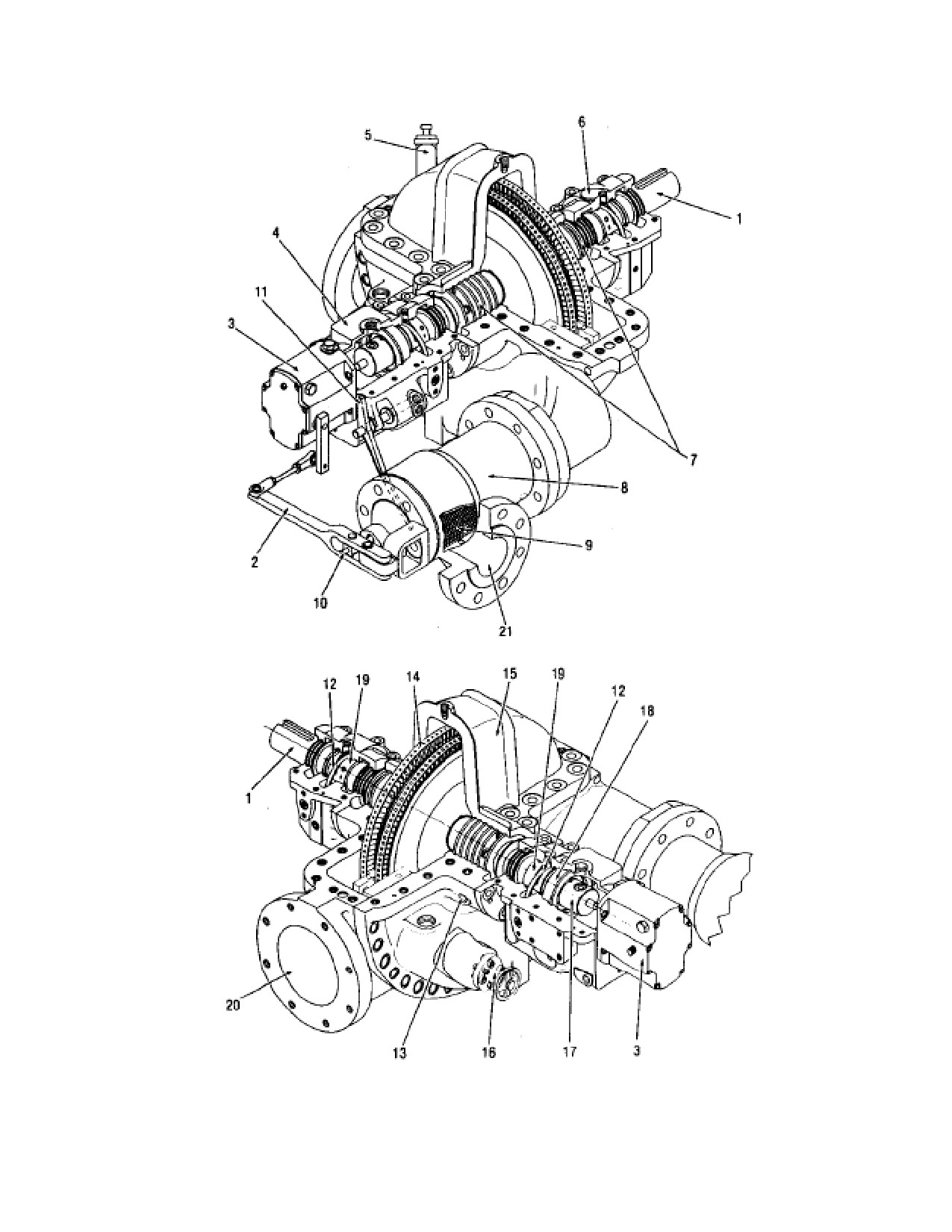
Your steam turbine is a single stage impulse type machine. A cut-away view of a
single stage turbine with a Woodward direct-drive speed governor is shown in
Figure A-1. Following is a description of the major components that comprise
the turbine.
Inlet Flange, 21. The standard SST turbine inlet flange for connection to the steam
supply is part of the over-speed Venturi trip. Flange type, size and material are a
function of the steam conditions and customer specifications. Refer to the certified
drawings in Appendix A following this manual.
Governor, 3. The main purpose of the governor is to maintain the set turbine
speed. The mechanical governors used for single stage turbines are direct
acting units mechanically linked to the governor lever for control of the
governor valve. Each governor is factory set to the customer’s specifications
for a specific speed range. The electronic governors maintain turbine speed
through the use of an actuator. The actuator adjusts the governor valve in
response to the signal received from the electronic governor. The Woodward
PG and UG governors are gear driven. For turbines with a Woodward
governor, Woodward bulletins, which describe operating characteristics and
maintenance instructions, are provided in Appendix B.
Trip & Throttle Valve. A single stage turbine may include a trip and throttle
valve, which is mounted between the turbine casing and the inlet steam line. It
normally houses both a throttle valve and over-speed trip valve. The overspeed trip
valve is a mechanically actuated valve which interrupts the supply of steam to the
turbine during an over-speed condition or other emergency, thereby bringing the
turbine to a complete stop. In the event of over-speed, the valve is activated by the
over-speed governor cup, which is attached to the turbine shaft inside the governor
housing. In the event of other emergencies, the valve can be activated using the
manual trip lever or an optional remote trip.
Governor Valve. The governor valve is automatically controlled by the speed
governor to admit the proper amount of steam required to maintain the speed for
which the governor is set. When the turbine is not operating, the valve is open,
unless options have been selected to close the valve when the turbine is tripped.
If your turbine has a special control system, a diagram is given in Appendix A.
Emergency Valve. The emergency valve, is automatically closed to shut
down the turbine on over-speed conditions, and manually when the trip
lever is unlatched. Some optional systems to automatically close this valve and
SST Turbine Instruction Manual
Revision A
27
Introduction and General Description
SST Turbine Instruction Manual
shut down the turbines are as follows: (Refer to Appendix A & B for turbines
with this equipment.)
Low oil pressure trip — on turbines with a pressure lubricating system.
Low air pressure trip — using the customer's air supply.
Solenoid trip.
High back-pressure trip.
Emergency Over-speed Trip Cup,
17. An emergency overspeed governor
assembly, located in a cup on the steam end of turbine shaft shuts down the turbine
when the turbine speed reaches the set trip-out speed. (Refer to turbine data sheets for
tripping speed of your turbine.) The trip mechanism is factory set and should require
no further adjustment. However, the tripping speed may be raised or lowered within
small limits. Procedures for this adjustment are given in section E-5.
Hand Valves, 16. Hand-operated nozzle control valves allow maximum efficiency at part
loads; rated load at reduced steam pressure, or operation at overload capacity. The valves
permit adjustment of the nozzle area to that which most closely conforms to the correct area
required by the steam flow for a particular load condition, thus reducing throttling.
Performance characteristics relating to the use of hand valves for your turbine are given on
the turbine data sheets.
As the steam leaves the governor valve it fills the steam chamber supplying the nozzle
ring. In the wall between this steam chamber and the nozzle ring are openings or ports
through which steam is fed to certain nozzles or groups of nozzles. In order to permit
the adjustment of the nozzle area as stated above, valves may be placed in as many of
these ports as is practical or required with the exception of one. This one port is under
control of the governor controlled inlet valve at all times. The hand valve ports are num-
bered, starting with the port located at the lowest point in the steam end and
proceeding in a clockwise direction. Thus, if a hand valve is furnished in the first port
it is designated as hand valve No. 1, in the second port, No. 2, etc. The valves must
be opened in their numerical order for best operation.
The hand valves cannot be used as throttling valves. They should be either fully opened or
fully closed. A valve that is partly open will soon have a damaged seat due to steam erosion. This
condition is better known as "wire drawing." However, when putting the unit into opera-
tion, do not close a valve tightly until the turbine is up to operating temperature and all parts
are evenly heated.
The reason for this is that the material of the valve stem is subject to greater thermal
expansion than the turbine casing, and if the valve is closed tightly when cold, it may
lock the valve in the closed position making it difficult to open.
28
Revision A
SST
Turbine
Instruction
SST Turbine Instruction Manual
Introduction and General Description
Main Bearings, 19. The turbine rotor is carried on two main bearings, which are
designated as the steam end and exhaust end bearings. The bearings are babbitted
sleeve type, with shoulders on the ends to maintain their axial position. A stop pin
prevents them from rotating with the shaft. Ball bearings also are main bearing options as well
as rare applications of tilt-pad bearings.
Thrust Bearing, 18. A ball or shoe type thrust bearing, located on the steam end of
the turbine shaft, prevents axial movement of the turbine rotor beyond designed
limits, (See Appendix A for the type of thrust bearing in your turbine.) The bearing
is properly positioned on the turbine shaft with shims at the factory and should
require no adjustment. However, it should be noted that the shims are responsible
for the proper nozzle-to-turbine wheel clearance. This is illustrated in Figure L-8
page 223. In pressure lubricated systems, the bearing operates in a continuous oil
bath. For ring oiled turbines, the ball thrust bearing receives the necessary oil
supply from the same oil ring that supplies oil to the main bearings.
Oil Rings, 12. For turbines without a pressure lubrication system, an oil ring,
located inside a slot in each main bearing, provides for lubrication of the main
bearings and the thrust bearing. During operation, the rings, which revolve freely
on the shaft, dip into the oil reservoir and carry oil up onto the shaft where it is
distributed to each main bearing. The thrust bearing, located inside the shell of the
steam end main bearing, receives its lubricating oil from this same action.
Shaft Packing, 7, 13. Carbon or labyrinth rings are provided at each end of the
turbine where the shaft passes through the turbine case. The turbine data sheets
specify the type and number of packing rings in your turbine, and the longitudinal
section drawing in Appendix A demonstrates the typical installation. Procedures
for replacement are given in Section L.5.2.
On non-condensing (back pressure) machines, the packing limits and controls the
flow of steam along the shaft. On condensing machines, the packing controls the
entrance of air into the casing at the packing glands where the pressure inside the
turbine case is less than atmospheric.
The carbon rings are individually separated in compartments formed by corrosion
resistant steel spacers. The partition rings are located in annular grooves in the
packing cases. The carbon rings seal by being forced against the spacers and by
being a clearance fit along the shaft. The rings are made in three sections and kept
from rotating by a stop on each ring. The ends of the ring segments are kept in
contact with each other by interlocking the ends. A stop prevents the assembly
from rotating.
SST Turbine Instruction Manual
Revision A
29
Introduction and General Description
SST Turbine Instruction Manual
Labyrinth packing is essentially a multiple tooth-throttling device, assembled
concentrically with the shaft. The rings, which are made of corrosion resistant steel,
are assembled in four segments with each joint numbered to facilitate identification
during replacement. The rings are located in the packing case by means of machined
shoulders.
Gland Sealing Systems. All condensing turbines have a gland sealing system to prevent air
from being drawn into the turbine casing through the packing glands. A typical schematic of
a sealing system, without a gland condenser arrangement, is shown in Figure C-6. If your
turbine requires a gland condenser system, a piping diagram with operating instructions is
included in Appendix A, along with a description of the major components that comprise the
system.
Pressure Lube Systems. For turbines with a pressure lube system, an oil piping or
schematic drawing for your turbine is provided in Appendix A. Ring oiled turbines
equipped with a separate, pressure lubricated, gear box may not require a diagram.
A typical schematic diagram of this system is shown in Figure 6. Since all turbines with
an integral gear box are pressure lubricated, this information, if applicable, is also
given in Appendix A. Turbines with pressure lube systems, that do not have an
automatic-start auxiliary oil pump, have oil rings to ensure lubrication of the bearings
during start-up, low speed operation and shut-down.
Oil Filter or Strainer. Either a strainer or an oil filter is provided in all pressure
lube systems. The filters are of the replaceable element type. A drop in normal oil
pressure may be an indication that the filter or strainer is clogged.
Twin filters with a transfer valve will allow changing an element without shutting
down the turbine. The twin units have a fill valve that should be used to fill the
side being placed into service, before the transfer is made. NOTE: Coolers and
filters are individually vented and the by-pass valves have been opened at start-up
or when any maintenance has been done on either component.
Certain systems, using a single element filter, incorporate a by-pass valve
arrangement to allow maintenance on the filter without shutting down the turbine.
In general, two basic types are employed; one system uses three separate valves
(Figure A-X, view A) and the other system uses a single two-position valve (3-way
or 4-way), shown in views B and C.
The two position valves are never closed. They are either positioned open to the
filter (normal operation), or open to by-pass (maintenance position). The shutoff
valve downstream of the filter in view B must be closed during maintenance. In
the three-valve arrangement, two valves are in series with the filter and one valve is
parallel. For normal operation, the two series connected valves are open; the
30
Revision A
SST
Turbine
Instruction
SST Turbine Instruction Manual
Introduction and General Description
parallel-connected valve is closed. For filter maintenance, the three valves are set
opposite their normal position.
Main Oil Pump. The pump can be direct-drive or gear driven from either the
turbine shaft, gear shaft, or governor shaft, depending on the application.
(See
Appendix A). No adjustments or special maintenance is required. For motor
driven main oil pumps, see turbine data sheets for electrical requirements.
Auxiliary Oil Pump (Motor Driven). Usually controlled automatically by a
pressure switch to start and stop at certain line pressure (See Turbine Data Sheets.)
A test valve in the system allows simulating a low oil pressure condition to check
operation of the pump. The pump should be tested at regular intervals.
Auxiliary Oil Pump (Steam Driven). Steam to drive the pump is controlled
automatically by a regulator valve. When oil line pressure is sufficient, the valve is
closed and the pump is inoperative. If oil line pressure drops, the regulator valve
opens and steam is admitted to drive the pump. A test valve allows simulating a
low-pressure condition to check operation of the pump. NOTE: it is important that
the pump exhaust is piped to atmosphere, and that the exhaust line be properly
drained.
*Low Oil Pressure Trip. The low oil acts to shut down the turbine when oil
pressure drops to an unsafe limit.
(See turbine data sheets). The device is mounted
on the steam end of the turbine and consists basically of a spring loaded bellows,
bellows stem, and a spring loaded plunger rod (See Appendix A). Bearing system
oil pressure keeps the device linked to the turbine trip latch. If bearing system oil
pressure decreases the device releases the trip latch and the turbine is shut down.
On certain turbines, oil pressure must be established in the system before the
emergency valve can be latched open.
*Low Air Pressure Trip. The air pressure trip allows shutting down the turbine
from a remote control. The device is identical to the low oil pressure trip described
in the preceding paragraph, except that facility air pressure in place of bearing oil
pressure keeps the device linked to the turbine trip latch.
*Turbines with the optional trip and throttle valve do not utilize a separate low
oil/low air pressure trip. This is a “built-in” feature of the trip & throttle valve
design.
Solenoid Dump Valve. In systems with a low oil/air pressure trip device, a
solenoid dump valve allows the shutting down of the turbine from a remote
location. The valve, when activated, opens and dumps system oil back to the
reservoir or air pressure to atmosphere. This creates a low oil/air pressure
SST Turbine Instruction Manual
Revision A
31
Introduction and General Description
SST Turbine Instruction Manual
condition and the turbine is shut down.
(See turbine data sheets for electrical
requirements and valve position when energized/de-energized.)
Circulating Systems. The circulating system is the next step up from the ring oil system
with water-cooling. This system is used when oil temperature in the bearing housings could
exceed 180°F (82°C). This elevated temperature is normally caused by an increase in
shaft/bearing rubbing speeds and/or elevated inlet or exhaust steam temperatures being
transmitted from the wheel casing to the bearing case itself.
The circulation system is basically a ring lubrication system, the difference being
that a shaft driven, direct drive pump, which circulates oil out of the bearing cases for
additional cooling, has been added. At high exhaust temperatures, an external oil cooler
is added to the system.
The pump supplied with this system is a positive displacement gear type pump. It is
mounted on the shaft at the exhaust end of the turbine. The upper half of the exhaust
end bearing case serves as a housing for the pump. The same pump is used regardless
of turbine rotation. The pump may be mounted off the turbine shaft at the steam
end when design allows.
A standpipe or overflow port is located at each bearing case to maintain the correct
oil level.
The circulating lube system has very limited options and is not an API system.
Figures A-1, Dresser-Rand SST Turbine, General View, Non-Drive End, & A-2,
Dresser-Rand SST Turbine, General View, Drive End, show major components, as
seen on the exterior of a standard turbine. Each major component is described in
detail below.
The Dresser-Rand manufactured Throttle Valve is contained in the steam chest or
valve body upstream of the over-speed trip valve. It controls the amount of steam
entering the turbine and thereby determines the speed and power produced by the
turbine.
Optional constructions may include separate throttle and/or over-speed trip valves
or other equipment configurations. Refer to the certified drawings in Appendix A.
Trip Linkage (not visible). This linkage connects the overspeed trip valve to the
trip mechanism inside the governor mounting housing. The trip linkage is activated
by the turbine shaft mounted over-speed trip collar, the manual over-speed trip
lever or an optional electric or electric/pneumatic trip actuator
32
Revision A
SST
Turbine
Instruction
SST Turbine Instruction Manual
Introduction and General Description
Immersion Heater. For turbines operating in an extreme environment, an optional
thermostatically controlled immersion heater may be provided in the main oil tank to
heat the oil prior to start-up and to maintain a suitable temperature during operation. If
your turbine has this equipment, a supplementary description and parts list is provided
in Appendix B. Operating procedures for this equipment are given in Section F.
Immersion heaters are not available on circulating lube systems.
Probes and Proximitors. An axial movement probe provides a means of
monitoring thrust bearing wear and radial probes monitor shaft vibration. For turbines
equipped to monitor vibration and axial displacement of the shaft, a probe assembly drawing
and an electrical wiring and layout drawing are provided in Appendix A with sup-
plementary instructions on the monitoring equipment.
In certain designs a key-phasor probe, shown on the electrical wiring and layout
drawing, is provided as an instrumentation reference point. The key-phasor is a separate
probe that may be axially or radially mounted.
LEGEND FOR FIGURE A-1
1. Turbine Shaft
12. Oil Rings (2)
2. Governor Lever
13. Packing Case Leakoffs (2)
3. Woodward TG Governor
14. Turbine Wheels
4. Steam End Bearing Case
15. Turbine Case
5. Sentinel Warning Valve
16. Hand Valve
6. Exhaust End Bearing Case
17. Overspeed Cup
7. Carbon Packing Rings
18. Thrust Bearing
8. Steam Chest
19. Main Bearings (2)
9. Steam Strainer
20. Exhaust
10. Governor Valve Stem
21. Inlet
11. Trip Lever
SST Turbine Instruction Manual
Revision A
33
Introduction and General Description
SST Turbine Instruction Manual
Figure A-1. Dresser-Rand SST, General View, Steam and Exhaust Ends
34
Revision A
SST
Turbine
Instruction
SST Turbine Instruction Manual
Introduction and General Description
Governor Lever, 2. This is the linkage between the governor and governor valve.
Over-speed Trip Lever, 11. The overspeed trip lever is part of the trip linkage,
allowing manual activation of the over-speed trip valve. Optional electric or
electric/pneumatic trip actuators and/or limit switches may be provided to work in
concert with the overspeed trip lever.
Over-speed Trip Reset Handle. This handle is used to reset (open) the overspeed
trip valve, permitting recovery from an over-speed trip condition. When recovering
from a trip condition, the handle is initially opened slightly to permit pilot valve
operation, and then is opened fully to reset the valve.
Steam End Bearing Case, 4. SST turbines have one sleeve shaft support bearing
and a thrust bearing in this housing. SST turbines can also have two ball bearings
serving the same purposes. The overspeed trip mechanism is located in this
housing and the over-speed trip lever is typically is mounted on this housing. The
standard housing also contains an oil ring, seals, the oil reservoir and the cooling
water jacket. Standard construction includes a constant level oiler mounted on the
bearing housing, along with the oil filler/vent, oil drain plug, and plugs for cooling
water inlet and outlet openings.
Exhaust End Bearing Case, 6. SST turbines have one sleeve shaft support bearing
in this housing and can also have one ball bearing serving the same purpose. The
standard housing also contains an oil ring, seals, the oil reservoir and the cooling
water jacket. Standard construction includes a constant level oiler mounted on the
bearing housing, along with the oil filler/vent, oil drain plug, and plugs for cooling
water inlet and outlet openings. This housing is similar to the steam end bearing
housing.
Oil Level Gauge. The oil level gauge indicates the oil level in the bearing housing.
This level corresponds with a mark inscribed on the bearing housing. For turbines
with alternate lubrication systems this may not be included.
Constant Level Oiler. The constant level oiler is an oil reservoir that is set to
maintain a constant oil level in the bearing housing. For turbines with force feed
lubrication or circulating oil cooling systems, oil levels are established by other
means.
Gland Housings. Gland housings of the standard SST turbine contain carbon ring
seals that prevent steam from leaking along the shaft to atmosphere. Some steam
will escape past the carbon rings, lubricating them. This steam is conveyed by the
gland leak-off connection to a safe location.
Alternate gland housing
configurations include labyrinth seals or mechanical seal designs.
SST Turbine Instruction Manual
Revision A
35
Introduction and General Description
SST Turbine Instruction Manual
Upper Case, 15. The upper case half contains exhaust steam and is the turbine
component that seals the turbine exhaust casing. It contains an eyebolt, used for
lifting the cover during turbine service. The eyebolt must not be used for lifting the
entire turbine.
Steam Chest, 8. The steam chest (or valve body) is the casing section containing
the high-pressure inlet steam. Steam enters the steam chest, travels past the trip and
throttle valve, trip valve, and through nozzles in the nozzle block.
Lower Case. The lower turbine case (exhaust casing) contains exhaust steam and
is integral with the exhaust flange. The exhaust casing supports the drive end
bearing housing.
Turbine Supports. The steam and exhaust end supports each consist of fabricated
steel or cast iron members that are bolted to the steam end and exhaust end casing.
The supports are drilled for mounting bolts and dowel pins that hold the turbine in
position and help maintain alignment with the driven equipment.
Exhaust Flange, 20. This flange connects the turbine to the user’s exhaust steam
line. Flange type, size, and material are a function of steam conditions and
customer requirements. Refer to the certified drawings in Appendix A.
Shaft Extension. This is the output shaft of the turbine, which is keyed to accept a
coupling.
Sentinel Warning Valve, 5. If specified, the turbine is supplied with a sentinel
warning valve. The valve will alarm when exhaust-casing pressure is excessive
(high). The valve warns the operator (by a whistle) only; it is not intended to
relieve the casing pressure.
A.4
Factory Test
All Dresser-Rand turbines are given a mechanical no-load run test at the factory
prior to shipment. The purpose of the test is to ensure the mechanical integrity of
the turbine and to adjust its controls, overspeed trip, and accessories, as required.
The standard test includes the following:
Turbine is run on shop steam conditions at rated speed, maximum continuous
speed and just below the overspeed trip speed.
36
Revision A
SST
Turbine
Instruction
SST Turbine Instruction Manual
Introduction and General Description
Vibration levels are measured and recorded at each test speed.
Turbine rotation & exhaust location are confirmed
Governor and speed control operation are checked
The over-speed trip is set and tested
Turbine is checked for steam and lubrication leaks
Sentinel warning valve is checked (if supplied)
For SST turbines a post-test visual inspection of each bearing and sleeve
bearing journal is carried out. If evidence of wear, scoring, or overheating is
found, the cause of the defect is corrected, and the turbine is re-tested and
inspected.
A.5
Shipping Preparation/Crating
Turbines are prepared for shipment and short-term storage (six months) using the
following procedure. After testing, the turbine is allowed to cool and all moisture is
drained from casings and valves. It is then masked and painted. All unpainted
surfaces not inherently corrosion-resistant, such as exposed portions of the shaft,
are coated with a rust-preventative and/or wrapped. Flange covers are installed on
all open-flanged connections. Rust inhibitor is sprayed inside the turbine. Oil in
bearing housings is drained and these cavities are partially filled with a rust
inhibiting and vaporizing oil. The turbine is mounted on a heavy wooden skid, and
depending on the shipping destination, is placed in a wooden container, covered or
wrapped with plastic.
Just prior to crating, the turbine is given a final inspection by a quality inspector,
who checks for completeness and appearance. Photographs of every turbine and the
accessories shipped with it are taken and become a part of the factory order file for
the turbine.
Refer to Section A.8, Long-term Storage, for additional measures taken if the
turbine is prepared for long-term storage.
A.6
Uncrating and Inspection
Remove the packing material and check all items against the packing list. Ensure
that parts are not missing or damaged. Handle all parts carefully. If inspection
shows that the turbine has been damaged during shipment, contact the carrier and
file a claim immediately.
Take care to ensure that loose parts are not discarded with the packing material.
SST Turbine Instruction Manual
Revision A
37
Introduction and General Description
SST Turbine Instruction Manual
CAUTION
Do not lift on the turbine shaft, as this could damage seals
and/or bearings, or may bend the turbine shaft.
A sling under each end of the turbine case can safely raise the
turbine. Do not use the eyelet in the center of the turbine case.
This eyelet should be used only for lifting the upper half of the
turbine case.
Refer to Figure B-1, Recommended Lifting Arrangement for Dresser-Rand SST
Turbines.
A.7
Short-term Storage
Dresser-Rand turbines shipped to United States destinations are prepared for short-
term storage of up to six months. The turbine should be stored in a clean, non-
corrosive atmosphere and protected against damage, loss, weather, and foreign
material, such as dust or sand. The equipment should remain on its shipping skid,
with all preservatives and covering left intact. Indoor storage is preferred, where
the temperature and humidity are maintained at a level preventing condensation.
When stored outdoors, the turbine skid should be raised sufficiently so as to avoid
contact with excessive moisture.
CAUTION
For turbines which will be subject to ambient temperatures of
-30°C (-20°F) or less, review and comply with all requirements
outlined in “Low Ambient Temperature Applications of Single
Stage ASTM A216-WCB Carbon Steel Pressure Casing Steam
Turbines” provided in the
“Miscellaneous” section of this
instruction manual.
Dresser-Rand turbines shipped to overseas destinations are prepared for short-term
storage of up to six months. The same general instructions stipulated for domestic
U.S. shipments also apply here.
38
Revision A
SST
Turbine
Instruction
SST Turbine Instruction Manual
Introduction and General Description
A.8
Long-term Storage
Long-term storage is defined as storage exceeding six months to one year.
The following instructions apply to turbines that are to be prepared for long-term
storage because they are not to be operated in the near future.
Basically these instructions apply equally to new units prepared for long-term
storage in the field or to units that have been operated but are to be taken out of
service for long-time storage.
The unit should be removed from the installed location (disconnect all steam,
water, drain, and leak-off lines) and stored in a clean, dry building which is not
subjected to large changes in temperature or humidity.
Long-term storage must be carried out in a warehouse maintained at constant
temperature, thereby preventing condensation. As with short-term storage, the
turbine should be protected against damage, loss, weather, and foreign material
such as sand or dust. The turbine should remain on its shipping skid and be raised
sufficiently so as to avoid contact with excessive moisture.
The following is the Dresser-Rand long-term storage procedure. This procedure
should be performed on turbines that will be subjected to long-term storage, if they
were not so prepared at the factory. The procedure should be repeated after the first
12 months of storage and checked at six-month intervals thereafter:
a. Remove the inlet and exhaust flange covers and spray the interior of the turbine
with rust-inhibiting and vaporizing oil; then replace the covers securely. All
machined parts (including internal parts such as oil pump gears and shafts, pins,
linkages, pilot valves, thrust bearing parts, governor parts
(except Woodward
governors), couplings, etc.) which are not painted should be coated with heavy
slushing compound; we recommend that the slushing compound purchased to MIL-
C-16173, Grade 1. All major oil companies can furnish such a slushing compound.
b. Partially fill bearing housings to a level corresponding to the bottom of the sight
glass with rust inhibiting and vaporizing oil. For SST turbines with sleeve type
bearings, coat the bearing and shaft journal surfaces with a rust preventative.
c. Fill governor with rust inhibiting and vaporizing oil. Woodward governors
should be filled to the top of the filler cup with the same type of lubricating oil
normally used in the Woodward governor. On units that have been operated in the
field, the old oil should be drained out and the Woodward governor should be
flushed with a clean light grade of fuel oil or kerosene before filling it with
lubricating oil.
SST Turbine Instruction Manual
Revision A
39
Introduction and General Description
SST Turbine Instruction Manual
d. Spray the exposed bonnet, seal blocks, and linkage areas of the trip and throttle
valve assembly with rust inhibiting and vaporizing oil.
e. Apply a rust-preventative coating on all exposed and machined surfaces of the
turbine. Do not apply this material to chrome plated areas of the turbine shaft. The
turbine rotor, the gear and pinion and the generator rotor can be stored in their
normal positions with the bearings in place; or they can be blocked up with wood
and the bearings removed for storage; or they can be removed from their normal
housings and blocked up for storage. In either case the journals should be carefully
cleaned, slushed and wrapped in waterproof, greaseproof, acid- free non-corrosive
paper (Sisal-Croft Fibreen or equal).
f. For turbines with carbon rings, after removing the upper case half, remove the
carbon rings, garter springs and stop washers. Coat the inside and machined
surfaces of the gland housings, along with casing and cover flanges exposed by the
removal of the upper case half, with rust-preventative grease. Reinstall garter rings
and stop washers on the shaft. Reassemble upper case cover onto the turbine. Store
the carbon rings separately and in original matched sets until the turbine is ready
for installation. This procedure will help protect chrome-plated areas of the turbine
shaft from corrosion damage. Turbines supplied with mechanical seals should not
have the seals disassembled. The outer surfaces of the seal may be coated to help
prevent external corrosion.
When prepared by Dresser-Rand for long-term storage, SST turbines have had the
carbon rings, garter springs, and stop washers removed as their removal helps
protect the shaft from corrosion. These components are packaged separately in a
box attached to the skid, and the turbine labeled with a long-term storage warning
tag. Installation of these components is necessary before the initial turbine start up.
Refer to Section L.4, Carbon Ring Removal and Replacement. The shaft packing
should be removed, tagged and prepared for storage. The packing ring segments
should be marked so that they can eventually be replaced in the turbine in their
control position.
Be sure that all water pockets are drained to eliminate danger of freezing). Piping
should be cleaned, dried and slushed.
To protect electrical insulation from vermin, the generator and exciter can be stored
in a vermin- proof housing. Do not get any slushing compound on the generator or
exciter insulation. Generator windings must be protected against absorbing
moisture.
It has been found that if a unit is stored in a clean dry building in which air is
circulated at approximately constant temperature it is not necessary to seal all
40
Revision A
SST
Turbine
Instruction
SST Turbine Instruction Manual
Introduction and General Description
openings, and the slushing needs only to be moderate. If it is decided to seal all
openings (after the flanges are slushed), use the special paper mentioned in Item 3
backed up by wood or light sheet metal. Place a good grade desiccant or some other
drying agent in the enclosure and arrange to inspect it at intervals of several
months.
If the unit is to be stored in the open, or in an uncompleted building, or in a
building that is subjected to large temperature changes, special precautions should
be taken such as:
Cover the unit with a tarpaulin and protect it with planking if building construction
is progressing in the vicinity of the unit.
Inspect at shorter intervals to determine if the slushing compound needs replacing.
A.9
Dresser-Rand Factory Service/Replacement Parts
Dresser-Rand provides a wide range of services to all its customers, including in-
house factory rebuilding of turbines, factory trained field service personnel,
replacement parts interchangeability lists, optimum replacement parts inventory
recommendations, and replacement parts. Vital spare parts, such as carbon rings,
gaskets, bearings, and valve components, are available for next-day shipment.
Selected Dresser-Rand manufacturer’s representatives maintain factory-authorized
repair facilities at locations throughout the world.
WARNING
SST Turbine Instruction Manual
Revision A
41
Introduction and General Description
SST Turbine Instruction Manual
Modification of, incorrect repair of, or use of non DRESSER-
RAND repair parts on this turbine could result in a serious
malfunction or explosion that could result in serious injury or
death. Such actions will also invalidate ATEX Directive &
Machinery Directive Certifications for turbines that are in
compliance with those European Directives. Refer to Section
M - Replacement Parts/Factory Service.
For assistance with service or spare parts, contact your local Dresser-Rand
manufacturer’s representative. Refer to Section M, Replacement Parts/Factory
Service, for additional information regarding identification of turbine parts.
A.10
Re-Rating and Upgrades
Most Dresser-Rand turbines can be re-rated for different steam conditions, speed,
or power. Contact your local Dresser-Rand manufacturer’s representative to
determine if a re-rate can meet your needs.
WARNING
Materials used in turbine construction (cast iron, steel, stainless
steel, special alloys) vary with steam conditions, speed, and
power. These materials were selected according to the original
rating of the turbine. NEVER attempt to RE-RATE a turbine
without the assistance of a Dresser-Rand manufacturer’s
representative and/or the factory. Misapplication of materials
COULD result in serious equipment damage and/or personal
injury.
Dresser-Rand turbines incorporate start-of-the-art technology and Dresser-Rand is
dedicated to making continuous improvements in its equipment to enhance
efficiency, maintainability and safety. In an effort to make improvements available
to owners of older Dresser-Rand steam turbines, the factory offers upgrade kits for
incorporating major design improvements into existing units. Consult your Dresser-
Rand manufacturer’s representative for information regarding factory upgrades.
42
Revision A
SST
Turbine
Instruction
SST Turbine Instruction Manual
Introduction and General Description
A.11
Nameplate Information
The following information is included on the turbine nameplate.
Turbine Serial Number
Turbine Type (Model)
Power
Speed - RPM
Normal Inlet Pressure
Normal Inlet Temperature
Normal Exhaust Pressure
Maximum Inlet Pressure
Maximum Inlet Temperature
Maximum Exhaust Pressure
Calculated First Critical Speed
Maximum Continuous Speed - RPM
Minimum Allowable Speed - RPM
Trip Speed
Purchaser’s Equipment number - If Specified
CE Mark - Followed by Notified Body Number when ATEX Category 2 is
specified by Purchaser
EX Mark - Followed by ATEX Group, Category, Atmosphere and EN 13463-1
warning related to User/Installer determined Inlet Temperature.
Manufacture Date (on CE/ATEX units)
Manufacturer’s name and location
SST Turbine Instruction Manual
Revision A
43
Introduction and General Description
SST Turbine Instruction Manual
44
Revision A
SST
Turbine
Instruction
SST Turbine Instruction Manual
Technical Data
Section B
Technical Data
B.1
General
Your Dresser-Rand single-stage turbine has been built specifically for your
application. Frame size, materials used in construction, nozzling, rotor
construction, and other items are based on steam conditions, power, and speed
specified in the original purchase order. This information is recorded in three
locations: 1) on the turbine nameplate; 2) on the turbine data sheet found at the
beginning of this manual; and
3) on the certified outline drawing found in
Appendix A. These documents also provide other important information, such as
installation dimensions, connection identification, connection sizes, weight,
component removal clearances, etc.
The turbine nameplate and data sheet specify the turbine serial number. This
number is a unique identifier for the turbine; it must be specified when ordering
replacement parts and in all correspondence with your local manufacturer’s
representative, the factory, and service personnel. The number is also stamped on
the horizontal flange of the inlet casing.
The following subsections discuss important technical considerations that must be
addressed when installing, operating, maintaining, or repairing the turbine.
B.2
Lifting
Turbines shipped on wooden skids should remain on their respective skids until
placement onto their permanent foundations. When a turbine is on its skid, the skid
should be used for lifting. Turbines shipped on base-plates can be lifted using
lifting provisions on the base-plate. Do not attempt to lift the turbine and base-plate
by lifting on the turbine or other base-plate mounted equipment.
When lifting the turbine itself, use slings extending around the steam chest and two
locations on the turbine casing, as illustrated in Figure B-1, Recommended Lifting
Arrangement for Dresser-Rand SST Turbines. Do not use the turbine shaft,
governor, or the cover (upper exhaust casing) eyebolt for lifting purposes. Lift
slowly and carefully to ensure stability and safety.
For correct sling selection, refer to the weights specified on the certified outline
drawing in the Appendix A.
SST Turbine Instruction Manual
Revision A
45
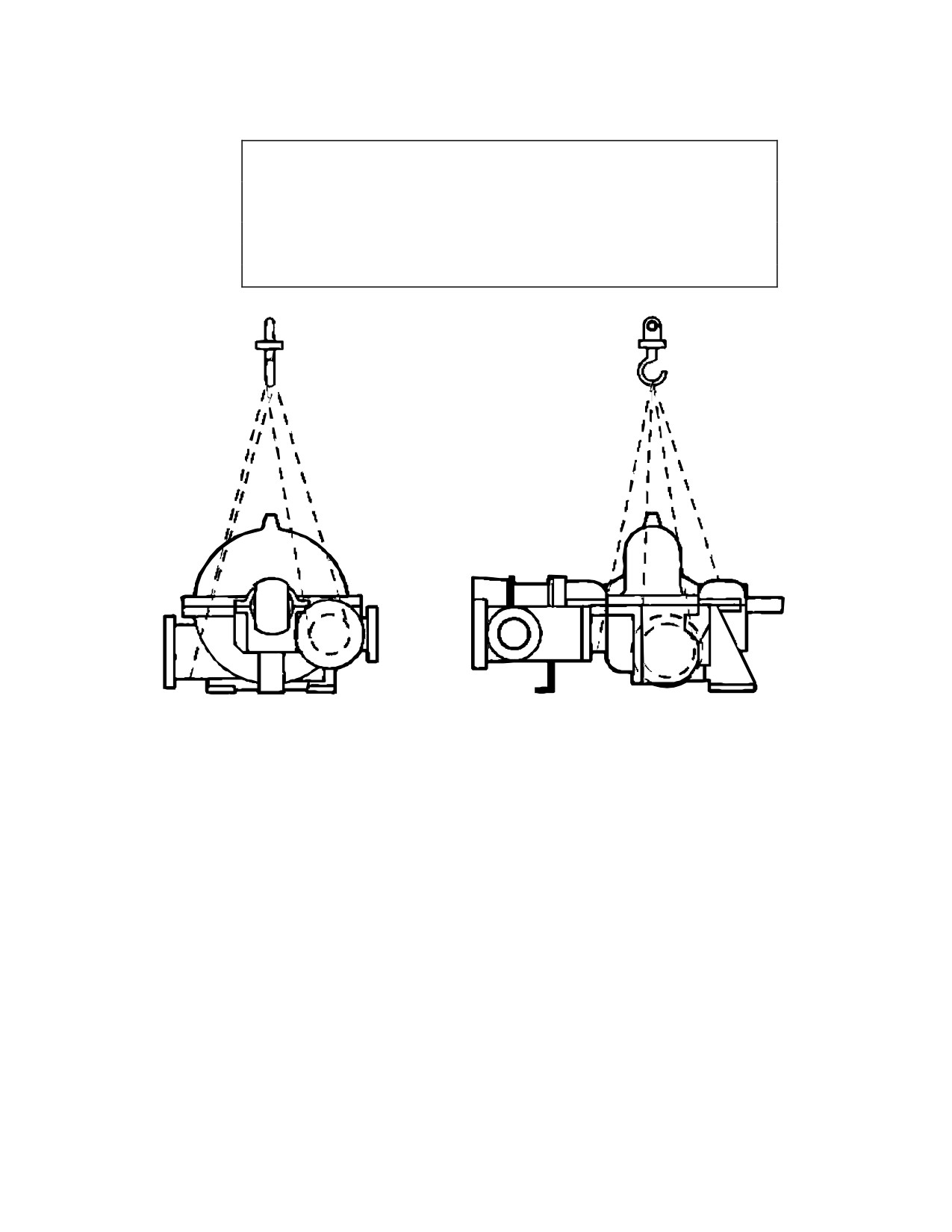
Technical Data
SST Turbine Instruction Manual
WARNING
Never attempt to LIFT the turbine USING the cover (upper
exhaust casing) EYEBOLT. This eyebolt is intended for lifting
the cover only. Using this eyebolt to lift the entire turbine
presents a SERIOUS SAFETY HAZARD.
Figure B-1. Recommended Lifting Arrangement for Dresser-Rand SST
Turbines
B.3
Alignment
Correct alignment of the turbine to the driven equipment is a primary consideration
in turbine installation. Improper alignment can result in vibration, as well as wear
and premature failure of bearings, seals, couplings, and shafts. Such failures can
occur not only in the turbine but in the driven equipment as well. Alignment should
be performed both under cold conditions and with the turbine at operating
temperature, using personnel experienced in turbine alignment. Refer to Section C,
Installation, for cold and hot alignment procedures. Alignment may be affected not
only by turbine positioning with respect to the driven equipment, but also by
thermal growth of the turbine, piping or the driven equipment, and by mechanical
46
Revision A SST
Turbine
Instruction
SST Turbine Instruction Manual
Technical Data
forces imposed by the piping. All of these factors must be considered when
installing the turbine.
WARNING
Misalignment with driven equipment or overload due to driven
equipment could result in excessive wear and bearing failure.
This could create sparks or hot surfaces could ignite lubricant
or flammable gasses.
CAUTION
Never put a steam turbine into service without first carefully
ALIGNING it to the driven equipment under cold conditions and
then again at operating temperature. Failure to do so may
result in premature FAILURE of both TURBINE and DRIVEN
EQUIPMENT components.
B.4
Thermal Growth
Thermal growth of the turbine casing supports, inlet/exhaust piping, and driven
equipment may result in misalignment and/or application of external forces on the
turbine. To avoid vibration and premature wear/failure of bearings, seals, couplings
and shafts, along with distortion of the turbine casing, the thermal expansion of
mating components must be carefully analyzed and compensated for by careful
alignment (both hot and cold), as well as the use of flexible shaft couplings,
expansion joints in piping, and proper maintenance of these components.
Refer to Section C, Installation, for cold and hot alignment procedures.
Refer to Section C-7
(Compensation for Thermal Movement) for further
information.
Refer to Appendix A in your manual for turbine thermal growth data.
Concerning temperature differential on turbines with built-up rotors, the disc-to-
shaft allowance tends to decrease to unacceptable limits with a
200°F (93°C)
temperature differential between the disc and shaft. The existence of such a condition is
greatest at approximately five minutes after start-up, rather than immediately at start-up.
Loss of the shrink fit can result in axial or wobble movement of the disc on the shaft,
SST Turbine Instruction Manual
Revision A
47
Technical Data
SST Turbine Instruction Manual
possibly resulting in turbine breakdown. The colder the unit at start-up, the greater the
probability of the temperature differential occurring. Since the utilization of forged discs
in lieu of plate discs allows a higher shrink fit, we normally recommend the customer
consider using forged discs.
In general, the subject of "quick," "fast" or "automatic" starting is not something
new in the steam turbine industry. Dresser-Rand has not decreased its engineering
standards for design of steam turbine shafts, bearings, or shrink fit of discs to shafts.
Reliability and durability are compromised by quick starting a turbine and will result in a
shortened overall turbine life. Frequent quick starts are particularly severe on bearings
and rotating elements. The more rapid the acceleration rate, the higher are the transient
loadings and the more severe are the loading effects. Dresser-Rand single stage
turbines with standard construction are suitable for start-up in five seconds provided the
following conditions are met:
1. The inlet side of the turbine steam line must be trapped.
2. Proper lubrication of bearings must be provided.
3. The inlet temperature of the steam shall not exceed 750°F (399°C).
4. The differential temperature between the inlet steam and exhaust steam shall not
exceed 350°F (177°C).
5. Back pressure shall be maintained on the casing during shutdown. (This in itself
is not a recommended operating condition due to possible shaft wire cutting or
carbon ring seal decay, but it will keep the casing warm.
6. The operating speed o f the turbine shall not exceed 6000 RPM.
7. The unit must be brought up under load.
B.5
Lubricants
The importance of using a proper lubricant cannot be over emphasized. High
quality turbo machinery oils are required. Dresser-Rand does not recommend
specific brands of oil. Turbine owners should consult reliable oil suppliers
regarding the proper selection of turbine oils. As a minimum, the selected oil
should be a premium quality rust- and oxidation-inhibited turbine or circulating oil
that will readily separate from water and have minimum tendency to emulsify or
foam when agitated at actual operating temperatures. Since the proper grade of
lubricant may not be available locally, it should be ordered in advance of the initial
start-up of the equipment.
Consult Section F, Lubrication for viscosity recommendations, bearing housing oil
capacities, oil levels, and maintenance of lubrication systems. In addition, a careful
review of the certified drawings in Appendix A must be made to insure any specific
48
Revision A SST
Turbine
Instruction
SST Turbine Instruction Manual
Technical Data
lubricant requirement applying to the supplied equipment package are
accommodated.
B.6
Major Fits, Clearances, and Rotor Balance Criteria
Dresser-Rand steam turbines are precision machines. The fits of the turbine wheel
to its shaft, bearings on the shaft and in their housings, and other fits are selected
and controlled so as to ensure long, efficient, trouble-free operation, as well as ease
of maintenance.
Whenever a turbine is disassembled and reassembled for inspection or parts
replacement, factory fits and clearances must be checked and maintained. If parts
do not fit properly on re-assembly, the reason must be determined and the problem
corrected.
Some major fits and clearances are listed in Tables B-1 Major Fits, Clearances, &
Rotor Balance Criteria - SST 350 and 500, B-2 Major Fits, Clearances, & Rotor
Balance Criteria - SST 500H Turbine and B-3 Major Fits, Clearances, & Rotor
Balance Criteria
- SST 700 Turbine. Other clearances are specified in the
appropriate subsection of Section L, Disassembly and Parts Replacement.
For overspeed governor trip setting see section L.14.1, for overspeed governor trip
linkage see L.14.3, for governor valve travel using Woodward PG and UG governors see
L.12.8 See L.14.4 for adjustment of the emergency valve travel.
SST Turbine Instruction Manual
Revision A
49
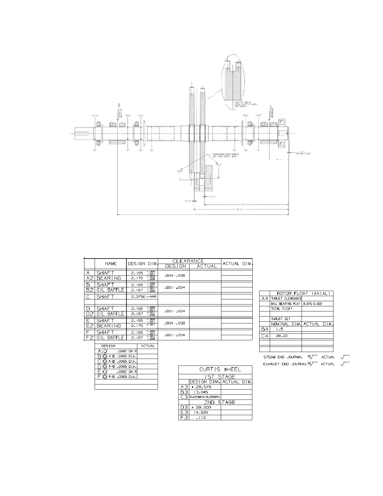
Technical Data
SST Turbine Instruction Manual
Figure B2 - Major Fits, Clearances and Rotor Balance Criteria - SST 350
Table B1 - Major Fits, Clearances and Rotor Balance Criteria - SST 350
50
Revision A SST
Turbine
Instruction
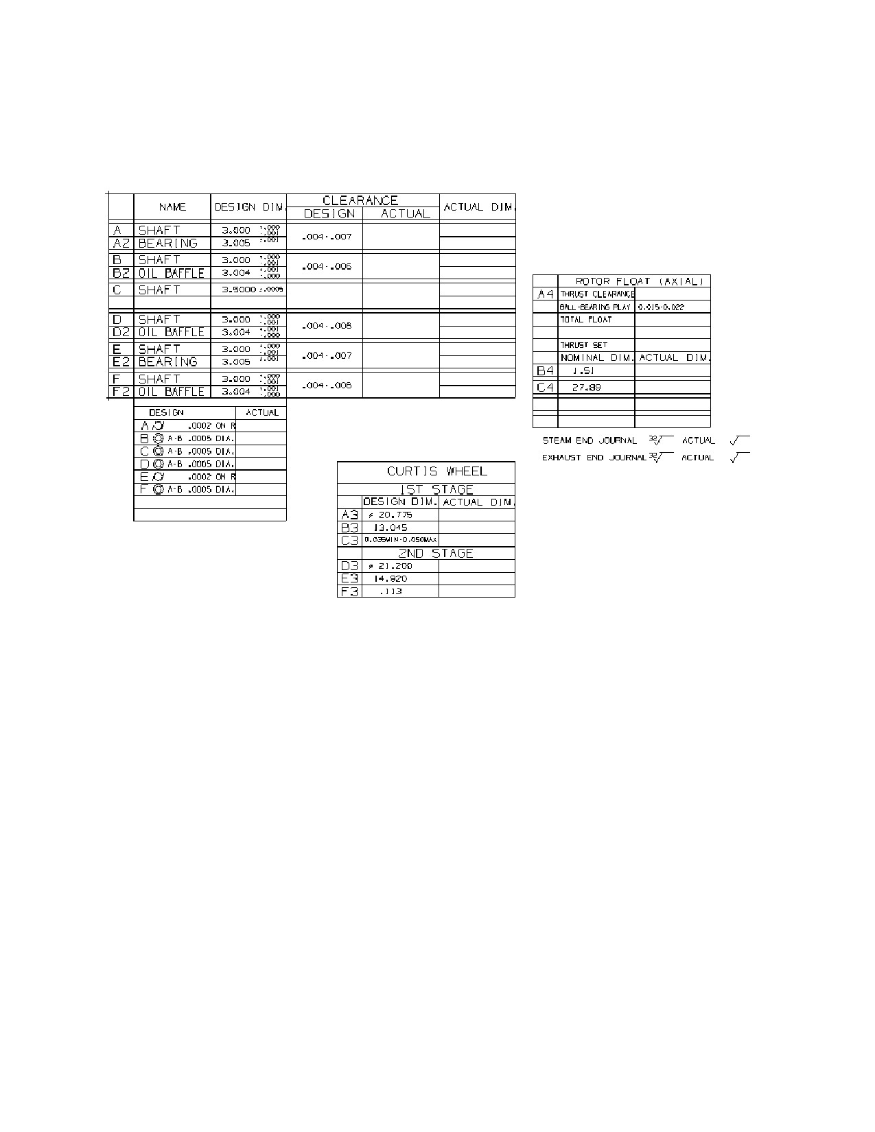
SST Turbine Instruction Manual
Technical Data
Table B-2. Major Fits, Clearances and Rotor Balance Criteria - SST 500
SST Turbine Instruction Manual
Revision A
51
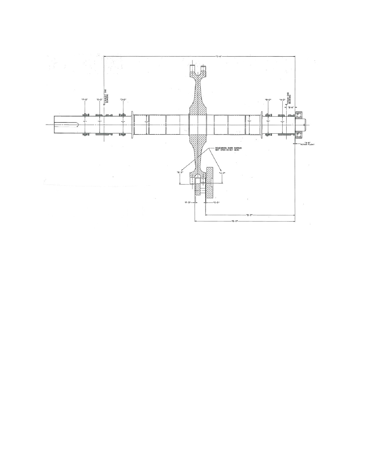
Technical Data
SST Turbine Instruction Manual
Figure B-3 Major Fits and Clearances, Standard SST 500 Turbine
52
Revision A SST
Turbine
Instruction
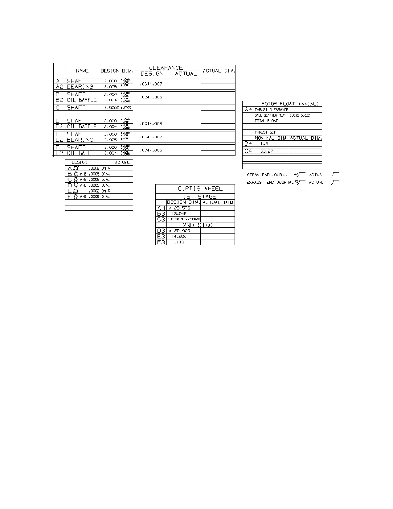
SST Turbine Instruction Manual
Technical Data
Table B-3.Major Fits, Clearances and Rotor Balance Criteria - SST 500H
SST Turbine Instruction Manual
Revision A
53
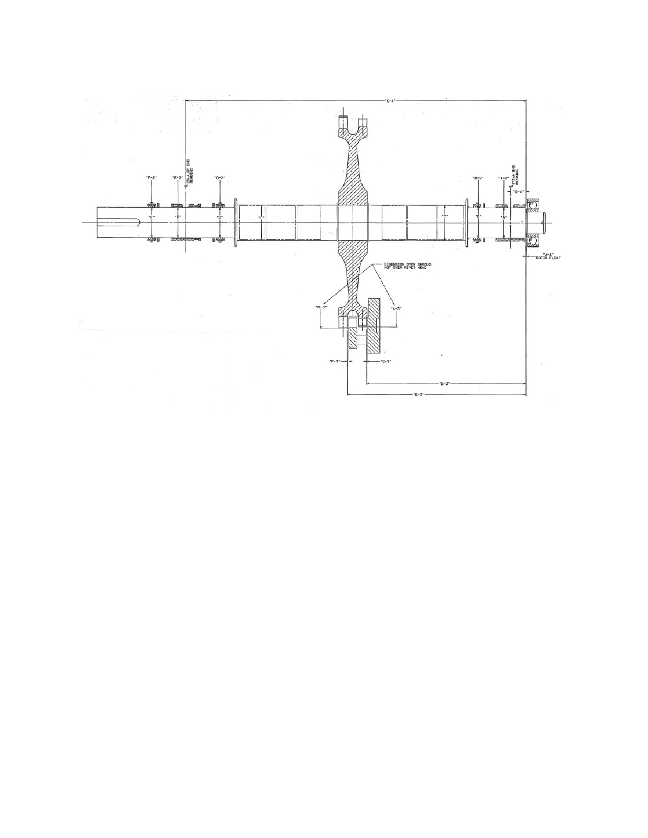
Technical Data
SST Turbine Instruction Manual
Figure B-4 Major Fits and Clearances, Standard SST 500H Turbine
54
Revision A SST
Turbine
Instruction
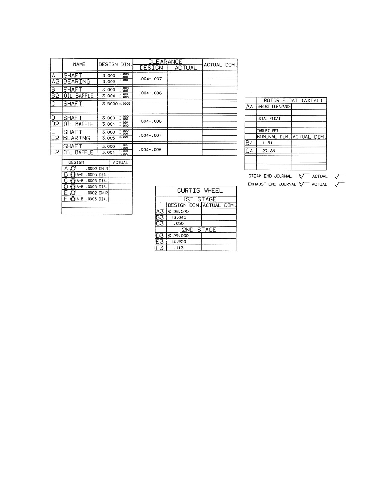
SST Turbine Instruction Manual
Technical Data
Table B-4.Major Fits, Clearances and Rotor Balance Criteria - SST 700
SST Turbine Instruction Manual
Revision A
55
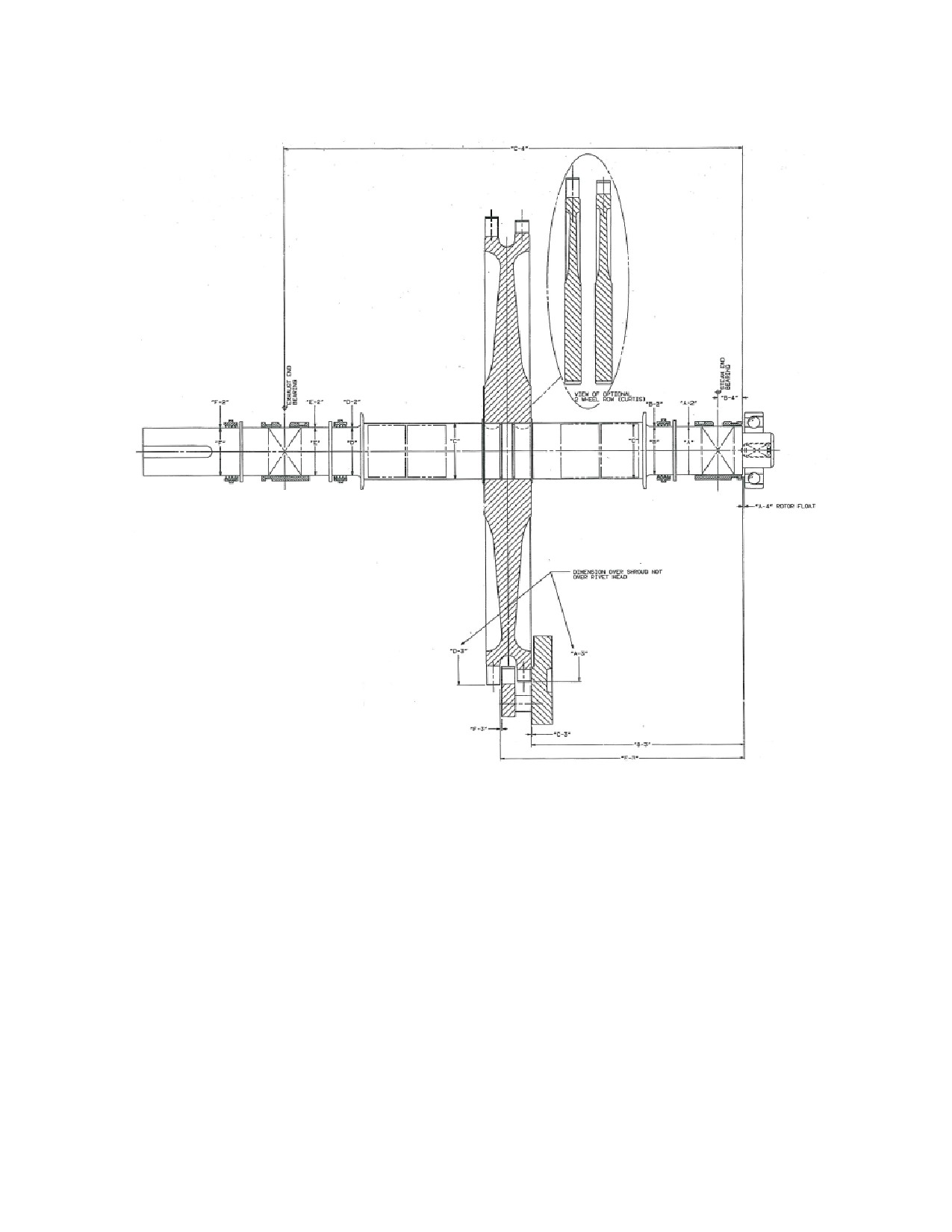
Technical Data
SST Turbine Instruction Manual
Figure B-5 Major Fits and Clearances, Standard SST 700 Turbine
B.7
Piping Forces
Steam piping, if improperly designed or installed, can impose severe mechanical or
thermal forces and moments on the inlet and exhaust flanges of a steam turbine.
Such forces and moments can misalign the turbine with its driven equipment, or
distort the turbine casing, resulting in internal misalignment of the turbine shaft
with bearings, seals, and other components. Such misalignment can cause vibration
and premature wear or failure.
To prevent excessive piping forces or moments, the customer must ensure that the
piping is designed and installed so as to comply with NEMA SM-23, Section 8,
56
Revision A SST
Turbine
Instruction
SST Turbine Instruction Manual
Technical Data
Allowable Forces and Moments on Steam Turbines. The maximum allowable
forces and moments are a function of pipe sizes and are tabulated in the certified
drawings in the Supplemental Documentation section, supplied at the end of this
manual. Additional piping information, including suggested piping layouts, can be
found in Section C, Installation.
B.8
Bolt Torques and Materials
The bolts used in Dresser-Rand turbines are carefully selected to ensure adequate
strength at the maximum temperatures and pressures the turbine is subjected to.
The following general application guidelines are used when selecting bolt
materials.
Turbine Construction
Bolt Material
Bolt Marking
A
Steel inlet/iron exhaust casings
B7
Bolts on trip and throttle valves
B7
B
Steel casings (below 775°F) (413°C)
B7
All pressure-containing
components
B7
B7
Or
Steel casings (carbon moly)
B16
above 775°F (413°C)
B16
Table B-5. Bolt Material and Markings
SST Turbine Instruction Manual
Revision A
57
Technical Data
SST Turbine Instruction Manual
WARNING
NEVER REPLACE THE ORIGINALLY SUPPLIED BOLT WITH
A SUBSTITUTE BOLT OF UNKNOWN OR LESSER GRADE.
DO NOT MIX BOLTS during assembly. Failure to use the
proper grade bolt could result in serious failure of pressure-
containing components
Torque ft-lbs. (N-m)
Inlet temp below
Inlet temp above
Bolt or Nut
775°F (413°C)
775°F (413°C)
Size (Inches)
B-7
B-16
Bolt Grade
45,000 PSI
60,000 PSI
½
53 (72)
71 (96)
5/8
106 (144)
141 (191)
¾
188 (255)
251 (340)
7/8
303 (411)
381 (519)
1
455 (617)
606 (822)
1 1/8
667 (904)
889 (1205)
1 ¼
937 (1270)
1250 (1695)
Table B-6. Standard Bolt Torques for Turbine Bolting
The above torques are based on the thread and nut or bolt seating areas being
lubricated with FEL-PRO C5-A high-temperature anti-seize compound or its
equivalent.
B.9
Sealants and Joint Compounds
The following sealants and joint compounds are recommended for the joined areas
specified.
58
Revision A SST
Turbine
Instruction
SST Turbine Instruction Manual
Technical Data
WARNING
Follow the manufacturer’s instructions for application of
sealants and joint compounds. Insure that personnel are aware
of and take precautions to avoid any hazards described by the
manufacturer.
Applicable Joints and Recommended Sealants and Joint Compounds
1.
All flanges and joints sealing steam at 600 PSIG (41.4 BAR) or less - Any of
the following:
Silver Seal
Turbo R and Temp-Tite String
Copaltite
Hylomar
Turboseal
Alinco or triple boiled linseed oil
Gortex Tape
Tem-Flex String Kit
Permatex #2 and #3
2.
All flanges and joints sealing steam at greater than 600 PSIG (41.4 BAR):
Turbo R and Temp-Tite String
Copaltite and Temp-Tite
3.
All flanges and joints sealing gas
Locktite Superflex Silicone Sealant
4.
Bolt and Stud Threads - Either of the following:
Never-Seez
Fel-Pro C-5A
5.
Bearing Housing Cover to Base
Locktite Superflex Silicone Sealant or other RTV style equivalent
SST Turbine Instruction Manual
Revision A
59
Technical Data
SST Turbine Instruction Manual
B.10
Cooling Water to Bearing Housing Water Jackets
Depending on the service conditions and the type of lubrication system supplied
with the turbine, bearing housings may require water cooling to maintain an
acceptable bearing oil temperature. Refer to Section F, Lubrication, for cooling
water requirements.
B.11
Steam Pressure and Temperature Limits
The steam temperature and pressure limits of Dresser-Rand turbines are limited by
the materials used in construction and the design of valve bodies, casings, casing
joints, seals, gaskets, and bolts.
WARNING
NEVER CONNECT the steam turbine to inlet or exhaust
sources of UNKNOWN PRESSURE OR TEMPERATURE, or to
sources whose pressure or temperature EXCEED limits stated
on the NAMEPLATE.
Dresser-Rand turbines can be re-rated for different steam conditions, powers and
speeds. Consult your Dresser-Rand manufacturer’s representative or the factory for
further information.
B.12
Steam Quality and Steam Purity
WARNING
THE DEGREE OF STEAM CLEANLINESS TOLERANCE ON
CONTROL VALVE AND TRIP VALVE COMPONENTS IS
LIMITED AND DEPOSITS MUST BE PREVENTED.
Steam quality must be dry and saturated or superheated. There must be provision to
remove moisture and condensate from the steam supply system to avoid damaging
the turbine. Governor valves, trip valves, trip throttle valves, etc. must be capable of
60
Revision A SST
Turbine
Instruction
SST Turbine Instruction Manual
Technical Data
closing in fractions of a second; and their movement cannot be impeded by deposits on
valves, seats, stems, etc. Deposits can form rapidly - as a result of improper water
treatment and/or entrainment of impurities in the steam supply.
The performance and reliability of a steam turbine can be adversely affected by the
admission of contaminated steam. When contaminants enter the turbine with the
steam supply, the usual result is the accumulation of deposits, which can be either
inert or highly reactive, depending on the contaminants present.
If the
contaminants are reactive, they can cause serious damage by corrosive attack on
the turbine materials.
To avoid these deposits, adequate boiler water chemistry control and other
precautions are required along with the need for constant surveillance during
operation and inspections. When deposits or material attack are noted during
inspection, investigations into the nature and origin of the contaminants should be
conducted and a program for corrective action begun.
The boiler water limits shown in Table B-5, Recommended Limits for Boiler Water,
are recommended for Dresser-Rand steam turbines to avoid the likelihood of
adverse affects from deposits and harmful ions. These limits are based on
operating history and recommendations from various consultants.
Pressure at
Outlet of
Total
OH
Silica,
Phosphate,
Hardness,
Chloride,
Steam
Solids,
Alkalinity,
ppm
ppm
ppm
ppm
Generating
ppm
ppm
Unit, PSIG
0 - 150
2000
200
50
50
0
250
151- 450
1500
100
35
50
0
200
451 - 750
1000
60
25
25
0
150
750 - 900
750
55
10
25
0
50
Table B-7. Recommended Limits for Boiler Water
SST Turbine Instruction Manual
Revision A
61
Technical Data
SST Turbine Instruction Manual
B.13
Turbine Rotor Data
Table B-7, Turbine Rotor Data for Standard Two-Row Wheel, provides basic
turbine rotor data. If further information is required, consult the factory.
Shaft Torsional
Rotor
Moment Of
Stiffness
Frame Size
Weight
Inertia
lb-in / RAD (N-m /
lb (kg)
lb-ft2 (kg-m2)
RAD)
SST 350
150 (68.0)
16.7
(0.70)
1.3 x 10⁶ (1.47 x 10⁵)
SST 500
220 (100.0)
47 (2.0)
5.1 x 10⁶ (5.76 x 10⁵)
SST 500H
230 (104.3)
47 (2.0)
4.7 x 10⁶ (5.31 x 10⁵)
SST 700
350 (158.8)
167 (7.0)
5.1 x 10⁶ (5.76 x 10⁵)
SST 700H
360 (163.3)
167 (7.0)
4.9 x 10⁶ (5.53 x 10⁵)
Table B-8. Turbine Rotor Data for Standard Two-Row Wheel
Notes:
1. For applications with Rateau rotors and/or non-standard shaft extensions,
consult the factory.
62
Revision A SST
Turbine
Instruction
SST Turbine Instruction Manual
Speed Control System
Section C
Installation
C.1
General
WARNINGS
Throughout this manual it is assumed that the motive flow applied at
the turbine inlet is high-pressure steam, therefore, the word “steam”
is used in reference to various aspects of turbine installation,
operation and maintenance. For some specialized applications,
high-pressure gasses such as Freon, natural gas or other vapors
may provide the motive flow In these cases, it can generally be
assumed, that the name of the gas in use may be used to replace the
word “steam.” The user of the equipment must address all hazards
associated with the nature of the specific motive flow in use with the
turbine. If flammable or toxic gasses are used as the motive fluid or
oil vapor could be emitted the user/installer must pipe leak-offs and
drains to a safe location. Explosive gas mixtures must not be used as
the motive fluid.
If the turbine is operated on a motive fluid other than steam due
consideration must be given to safety issues that might relate to the
medium used, including but not limited to the ignition, explosion or
poisoning of personnel.
The surface temperature of the turbine and piping will become that of
the steam inlet temperature. This could exceed the ignition
temperature of some gasses. Therefore if the turbine is installed
where explosive gasses could be present it is the user's responsibility
to insure that this does not create a hazardous situation.
The turbine must be properly grounded, thereby by preventing
electrical shock or sparks that could cause injury or ignition of
flammable gasses or liquids in the event of failure of electrical
accessories, driven equipment or the creation of a static electrical
charge.
SST Turbine Instruction Manual
Revision A
63
Installation
SST Turbine Instruction Manual
WARNINGS
If the turbine is supplied with oil mist lubrication oil mist could escape
from the bearing housing vents or constant level oiler. If there is the
possibility that these could be ignited by equipment of processes in
the proximity of the turbine they should be piped to a safe area.
Lighting must be installed in the installation area to insure that
operators can see the turbine and its controls.
Do not install the turbine where ambient temperature could be -20°
F or less unless this was specified in the original order and LOW
TEMPERATURE materials have been provided. Refer to Section F,
Lubrication System, for ambient temperature limits based on
lubrication.
Proper installation of the turbine and driven equipment is vital for successful
operation of the system. It is for this reason that competent, experienced personnel
should be employed during installation. Before installing turbine refer to the
certified drawings in Appendix A of this manual.
Dresser-Rand recommends that API Recommended Practice RP-686 be consulted
for additional guidance in regard to the installation of the turbine and driven
equipment package. It provides recommended procedures, practices and quality
assurance checklists covering the installation and de-commissioning of turbines,
compressors, fans, motors, gear reducers and pumps for use in petroleum,
chemical, gas industry and other facilities.
The following subsections, C.2 through C.11, provide basic installation and
decommissioning procedures. Follow them in the indicated sequence for complete
and correct installation. These recommendations and instructions are provided to
assist the purchaser and/or his contractor. Fully qualified labor, including qualified
supervision, is required for proper installation, start-up, and subsequent operation
of the equipment. The services of a Dresser-Rand serviceman are recommended for
the final on site installation review and the initial commissioning and start-up of the
turbine.
As a minimum the following steps must be carried out in sequence to achieve
satisfactory operation.
64
Revision A SST
Turbine
Instruction
SST Turbine Instruction Manual
Speed Control System
WARNINGS
NEVER CONNECT the steam turbine to inlet or exhaust
sources of UNKNOWN PRESSURE OR TEMPERATURE, or to
sources whose pressure or temperature EXCEED limits stated
on the NAMEPLATE.
Misalignment with driven equipment or overload due to driven
equipment could result in excessive wear and bearing failure.
This could create sparks or hot surfaces could ignite lubricant
or flammable gasses.
a.
Refer to the certified drawings in Appendix A and carefully read all
installation notes, piping connection details, dimensions and clearances, and
any other special data.
b.
Provide a proper and adequate foundation for the turbine.
c.
Provide a proper piping installation, in accordance with NEMA SM23, that
will accommodate pressure forces and thermal growth without imposing
excessive force on the turbine.
d.
Remove all protective coatings and foreign matter from the turbine and all
piping. If the turbine was prepared for long-term storage, reinstall the matched
carbon ring sets, springs and washers into the turbine gland housings.
e.
Refer to coupling alignment instructions supplied by the coupling
manufacturer, as well as those supplied in this manual.
f.
Perform an accurate cold alignment.
g.
Grout the base-plate or sole plate to the foundation, as required.
h.
Carefully check hot alignment at operating temperature and adjust it, if
necessary, to establish accurate alignment.
i.
Dowel turbine and driven machine in place to maintain proper alignment.
C.2
Foundation
WARNING
SST Turbine Instruction Manual
Revision A
65
Installation
SST Turbine Instruction Manual
If the turbine is installed in a location where there is the
possibility of an earthquake this must be considered in the
design of the piping and foundation.
The foundation is one of the most influential factors governing overall reliability of
a turbine. A foundation must maintain alignment under all normal and abnormal
conditions. This includes the way a foundation is supported on the soil and/or
superstructure, soil settling, soil resonances, thermal distortion, piping forces, and
vacuum pull or pressure forces in expansion joints.
The turbine, gear reducer (if used), and driven equipment should all be mounted on
a common foundation.
Sufficient space should be provided around and above the foundation to allow for
proper installation and maintenance.
The foundation must minimize vibration by being as heavy as possible and non-
resonant. It is important that the turbine be isolated from external vibration. Neither
the foundation nor related support structure should be resonant within the operating
range of the turbine.
Vibration transmissions may occur from the unit to the surroundings, or vice versa;
vibration may also be aggravated by resonance at transmission frequencies. Piping,
stairways, and ducts may also transmit vibration, which should be prevented by
proper isolation.
A certified outline drawing is furnished with each Dresser-Rand turbine and is
included in this manual in Appendix A. This drawing includes dimensions for
locating anchor bolts, equipment weights, and general information required for
determining foundation dimensions and design.
A generous safety factor should be used when determining foundation thickness.
The foundation length and width should extend at least 6 inches (152 mm) beyond
the anchor bolts.
Anchor bolts must be positioned accurately and provided with sleeves. The sleeve
bore diameter should be approximately twice the bolt diameter, but should provide
not less than 1/2” (13 mm) clearance all around the bolt.
Carefully constructed templates are required to hold bolts and sleeves in position
while the foundation is cast. Templates are usually made of wood and secured to
the foundation forms. Experienced workers should be able to set anchor bolts to a
tolerance of 1/8” (3 mm) by locating and drilling holes in the template after they
have been secured to the braced forms.
66
Revision A SST
Turbine
Instruction
SST Turbine Instruction Manual
Speed Control System
Anchor bolts should be threaded at both ends and be of sufficient length to extend
one-and-a-half to twice the bolt diameter above the top of securing holes in the
base plate or the sole plate. The lower end of each bolt is enclosed in a sleeve and
passes through an anchor plate, where it is secured by a nut to which it is welded.
Anchor plates can be either washers or plates of cast iron or steel. They should
have a diameter or side dimensions of approximately twice to two-and-a-half the
outside diameter of the sleeves.
Notes:
1.
Templates must be rigid enough to prevent bolts from shifting while the
concrete is being poured.
2.
After concrete has been poured and before it has hardened, recheck positions
of the anchor bolts.
3.
Allow a 1-1/2” (38 mm) gap above the top of the foundation surface for
grouting under edges of the base plate or sole plates.
C.3
Piping
WARNING
Improperly designed or installed piping can lead to turbine
misalignment and failure of the turbine or driven equipment. It
is the user/installers responsibility to insure that the piping
system is properly designed, installed and that it meets local
codes and regulations. All references to piping design in this
section are for reference only.
SST Turbine Instruction Manual
Revision A
67
Installation
SST Turbine Instruction Manual
WARNING
If the turbine is installed in a location where there is the
possibility of an earthquake this must be considered in the
design of the piping and foundation.
Proper piping of a steam turbine is essential. Correctly designed and installed
piping contributes to safe, trouble-free operation and can improve ease of turbine
operation and maintenance.
Before installing any piping, installation personnel should read and become
thoroughly familiar with this section.
The effects of possible earthquakes should be taken into account when designing
the inlet and exhaust piping systems.
C.3.1
Piping Forces
Any pipe connected to the steam turbine casing, valves, gland housing, or bearing
housings can exert forces and/or moments on the turbine. This can misalign the
turbine with its driven equipment or distort the turbine casing, resulting in internal
misalignment of the turbine shaft with bearings, seals, and other components. Such
misalignment can cause vibration, premature wear or failure of bearings, seals,
couplings and shafts, and casing leaks.
Steam supply (inlet) and exhaust piping, being relatively large and subjected to
higher temperatures and pressures, can, if improperly installed, exert relatively
large forces and moments on a steam turbine. Leak-off, drain, lube, cooling water
and gland seal piping does not normally transmit significant piping forces.
To prevent excessive piping forces or moments, the customer must ensure that the
piping is designed and installed so as to comply with NEMA SM-23, Section 8,
Allowable Forces and Moments on Steam Turbines. The maximum allowable
forces and moments are a function of inlet and exhaust flange sizes. Flange sizes
are tabulated on the Certified Drawing appearing in Appendix A.
Piping forces can be reduced or eliminated with proper piping design, the use of
expansion joints, and correct piping support systems. Figure C-1, Suggested Steam
Inlet and Exhaust Piping Arrangement, suggests inlet and exhaust piping systems,
showing typical expansion joints, piping loops, and spring supports in the piping
system.
68
Revision A SST
Turbine
Instruction
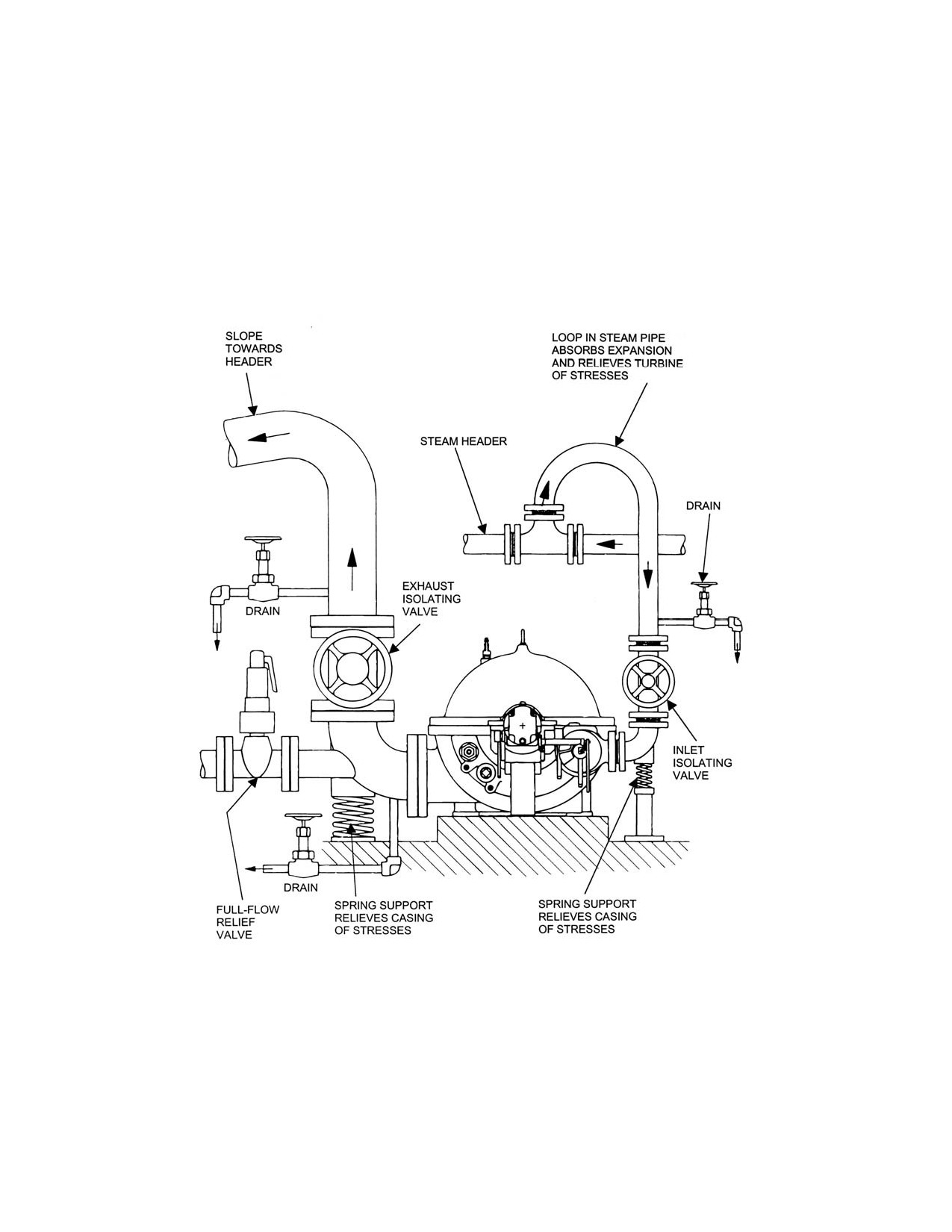
SST Turbine Instruction Manual
Speed Control System
Optional constructions, which include third-party throttle and/or over-speed trip
valves or other equipment configurations, may require the use of additional supports.
Refer to the certified drawings in the Appendix A.
Refer to a separate sketch in Appendix A for the estimated thermal movement of the
inlet flange and exhaust flange. The estimated thermal movements of the inlet and
exhaust flanges are used in the design and analysis of the piping support system.
Figure C-1. Suggested Steam Inlet and Exhaust Piping Arrangement
C.3.2
Isolating Valves
SST Turbine Instruction Manual
Revision A
69
Installation
SST Turbine Instruction Manual
Inlet and exhaust lines to a turbine must be provided with isolating valves. The
purpose of these valves is to isolate the turbine from inlet and exhaust systems,
allowing the turbine to be shut down, along with sealing inlet and exhaust lines if
the turbine is to be moved or serviced.
DANGER
NEVER DISCONNECT inlet or exhaust piping of the turbine
without first CLOSING and TAGGING the ISOLATING VALVES
and then OPENING DRAIN VALVES SLOWLY to relieve any
pressure within the turbine. Failure to do so may expose
PERSONNEL to SERIOUS INJURY if steam was to be
introduced into the piping or captured in the turbine. As an
added precaution, always install blank flanges on inlet and
exhaust lines after removing the turbine.
The inlet piping isolating valve should be installed immediately upstream of the
turbine. Refer to Figure C-1, Suggested Steam Inlet and Exhaust Piping
Arrangement.
The exhaust piping isolating valve should be installed immediately downstream of
the full flow relief valve. Refer to Figure C-1, Suggested Steam Inlet and Exhaust
Piping Arrangement.
C.3.3
Full Flow Relief Valve
An atmospheric relief valve must be installed between the turbine exhaust flange
and the first exhaust line shut-off valve (Refer to Figure C-1, Suggested Steam Inlet
and Exhaust Piping Arrangement). The purpose of this relief valve is to protect the
turbine casing from excessive exhaust pressure. The relief valve must be of ample
size to pass the maximum quantity of steam flowing through the turbine at the
maximum inlet temperature and pressure steam conditions without allowing the
turbine casing pressure to exceed the limit defined below. It is the user’s
responsibility to install the relief valve in the piping.
The full flow relief valve shall begin to open at 10% or 10 PSIG (69 kPag) above
maximum exhaust pressure, whichever is greater, for non-condensing turbines; and
at not more than 10 PSIG (60 kPag) for condensing turbines. The valve shall be
fully open with an additional rise in pressure not to exceed 10%. Refer to NEMA-
23, Steam Turbines for Mechanical Drive Service, for further details.
70
Revision A SST
Turbine
Instruction
SST Turbine Instruction Manual
Speed Control System
WARNINGS
It is the USER’S RESPONSIBILITY to INSTALL A FULL-FLOW
RELIEF VALVE in the exhaust line between the turbine exhaust
casing and the first shut-off valve. This relief valve should be
sized to relieve the FULL AMOUNT OF STEAM THAT THE
TURBINE WILL PASS, in the event that the exhaust line is
blocked.
The optional SENTINEL WARNING VALVE, located on the
turbine casing, DOES NOT SERVE as a RELIEF VALVE. The
sentinel warning valve WILL NOT PASS SUFFICIENT STEAM
FLOW to relieve the turbine casing of EXCESSIVE EXHAUST
PRESSURE. The purpose of the sentinel warning valve is to
warn visually and audibly that excessive pressure is building in
the turbine exhaust casing.
C.3.4
Inlet Piping
As shown in Figure C-1, Suggested Steam Inlet and Exhaust Piping Arrangement,
inlet piping should come off the top of the steam header and form an expansion
relieving loop or other strain relieving device, before coming down to the turbine.
A valved condensate drain should be installed in the inlet line upstream of the
isolating valve, allowing condensate to drain prior to opening the isolating valve
and feeding steam to the turbine. Piping must be supported in such a manner as to
allow thermal growth of the turbine and piping, without imposing excessive forces
and moments on the inlet flange. Properly installed piping should mate squarely to
the turbine inlet flange, without any need to force flanges by twisting them into
alignment when connecting them.
The inlet line should be well lagged to prevent heat loss and to avoid burns.
Pipe sizes should be large enough to maintain rated steam pressure at the turbine
inlet flange under maximum load conditions. In determining pipe size, proper
allowance should be made for pressure drop due to long sections of pipe, elbows,
valves, or other fittings between the boiler and the turbine.
If wet or saturated steam is used, it is very important that piping be arranged so that
condensate cannot be carried over into the turbine. A steam separator of the proper
size, with a trap of ample capacity, should be installed before the turbine inlet. All
horizontal runs must be sloped up in the direction of steam flow, with drains at the
low points.
SST Turbine Instruction Manual
Revision A
71
Installation
SST Turbine Instruction Manual
The importance of protecting the turbine against slugs of water cannot be
overemphasized. The issue is not “wetness” of the steam, but with condensate,
which is separated out as water. The harmful effects of water are:
1. Rapid erosion of blading and valves.
2. In the case of turbine wheels with inserted blades, water may have a hammer-
blow effect, tearing out the blades and destroying the rotor.
3. Governing is adversely affected.
4.
The rotor may be permanently distorted and/or the turbine may be seriously
damaged.
5.
A danger of thrust bearing failure and consequent destruction of the turbine.
C.3.5
Exhaust Piping
Figure C-1, Suggested Steam Inlet and Exhaust Piping Arrangement, shows
exhaust piping together with the full flow relief valve and support system. Note that
the exhaust line should slope down toward the header or create an overhead loop,
to prevent condensate at the header from flowing back toward the turbine. Valved
drains should be installed before and after the exhaust-isolating valve.
On each installation, the length of run, elbows, valves, and other fittings in the pipe
must be considered, together with all factors, which may cause back-pressure on
non-condensing turbines or reduced vacuum on condensing turbines, and a final
decision on piping size made accordingly. On non-condensing turbines, back-
pressure which is higher than what the turbine was designed for will cause
reduction of power and an increase in steam consumption. It may also cause gland
leakage, and in extreme cases, can rupture the turbine casing. On condensing
turbines, decreased vacuum will have an even greater effect on capacity and
economy.
The exhaust pipe must be installed and anchored so that no excessive stress is
placed on the turbine from either the weight of the pipe or its expansion and
contraction. In cases where such an arrangement cannot be made with certainty, an
expansion joint near the turbine can be useful in low pressure lines and is usually
required on large pipe sizes. The use of an expansion joint does not of itself avoid
undue stress. It is not as flexible as many people assume and when installed, it must
be properly aligned and not indiscriminately exposed to shear or torsion. In the
majority of applications, axial thrust created on the cross-sectional area of the
largest bellows, by internal pressure, must be restricted by the use of tie rods. They
are most effective when the expansion joint is used in shear, instead of tension or
compression. When used in either a vacuum or a pressure line, tie rods must be
72
Revision A SST
Turbine
Instruction
SST Turbine Instruction Manual
Speed Control System
arranged accordingly. They are useless where a joint moves under tension or
compression, as they bypass the joint and transmit pipe forces directly to the
turbine. Provision must be made to anchor the piping in such a way that excessive
forces will not be transmitted to the turbine during shutdown and operational
running. Connection to a header must be made at the top, never from the bottom or
side, and great care must be taken to avoid draining water back into the turbine. All
horizontal runs must be sloped away from the turbine exhaust connection.
Properly installed piping should mate squarely to the turbine exhaust flange,
without any need to force flanges by twisting them into alignment when connecting
them. The exhaust line should be well lagged to prevent heat loss and avoid burns.
C.3.6
Piping Blow Down
Newly constructed steam piping should be blown-down to remove scale, weld slag
and any other foreign material. Such material can cause severe damage if it enters
the steam turbine.
After inlet piping has been installed, but before connecting it to the turbine, steam
should be blown through the line and into the exhaust line to remove welding slag
and debris.
Refer to NEMA SM-23, Steam Turbines for Mechanical Drive Service or a reliable
piping contractor for a blow-down procedure.
CAUTION
INLET STEAM LINES MUST BE BLOWN DOWN PRIOR TO
CONNECTING them to the turbine. Debris and welding slag
can cause serious damage to valves, nozzles, and turbine
blading if allowed to enter the turbine.
C.3.7
Steam Strainer
Standard SST Dresser-Rand turbines are provided with integral inlet steam
strainers to prevent entry of foreign material into the turbine. Part of the throttle
valve is located in the same chamber with the steam strainer. The steam strainer
will allow small debris particles to pass through the turbine and does not preclude
the need for inlet piping blow-down prior to connecting the turbine. The steam
strainer should be removed and cleaned at least once a year and replaced at least
every three years or as needed.
When a turbine is supplied without an integral or separate y-type strainer, the
purchaser must install an appropriate steam strainer in the inlet steam piping.
SST Turbine Instruction Manual
Revision A
73
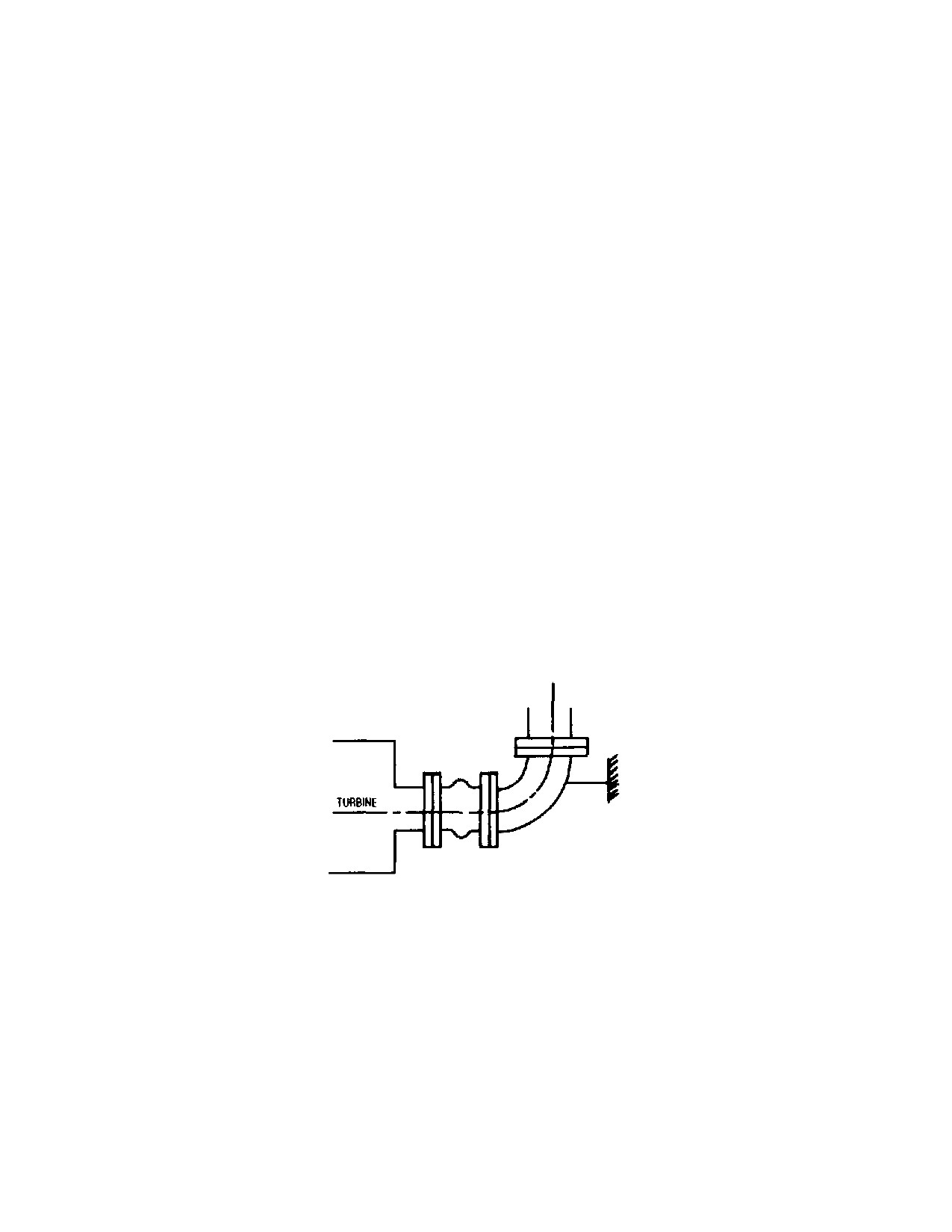
Installation
SST Turbine Instruction Manual
C.3.8
Check Valve
Where a turbine exhausts or bleeds steam into another system, and a check valve
(commonly referred to as a non-return valve) is installed for prevention of reverse
flow to the turbine, adequate bracing must be installed to absorb any forces created
by water hammer effects occurring in the exhaust line downstream and acting on
the check valve. The maximum relief valve settings are found on the turbine data
sheets. The sentinel relief valve on the turbine case is a warning valve only.
C.3.9
Expansion Joints
Low pressure and vacuum lines are usually large and relatively stiff. It is common
practice to use an expansion joint in these lines to provide flexibility. If an
expansion joint is improperly used, it may cause a pipe reaction greater than the
one that it is supposed to eliminate. An expansion joint will cause an axial thrust
equal to the area of the largest corrugation multiplied by the internal pressure. The
force necessary to compress or elongate an expansion joint can be quite large, and
either of these forces may be greater than the limits for the exhaust flange. In order
to have the lowest reaction; it is best to avoid absorbing pipeline expansion by axial
compression or elongation. If it is found that expansion joints are required, it is
essential that they be properly located and their foundation rigid. Refer to NEMA
SM-23, Steam Turbines for Mechanical Drive Service or a reliable piping
contractor for steam piping system design and installation guidance.
See Figure C-2 Unrestrained Expansion Joint (not recommended).
Figure C-2. Unrestrained Expansion Joint (Not Recommended)
The axial thrust from the expansion joint tends to separate the turbine and the
elbow. To prevent this, the elbow must have an anchor to keep it from moving. The
turbine must also absorb this thrust, and in so doing, it becomes an anchor. This
force on the turbine case may be greater than the allowable force. In general, this
method should be discouraged.
74
Revision A SST
Turbine
Instruction
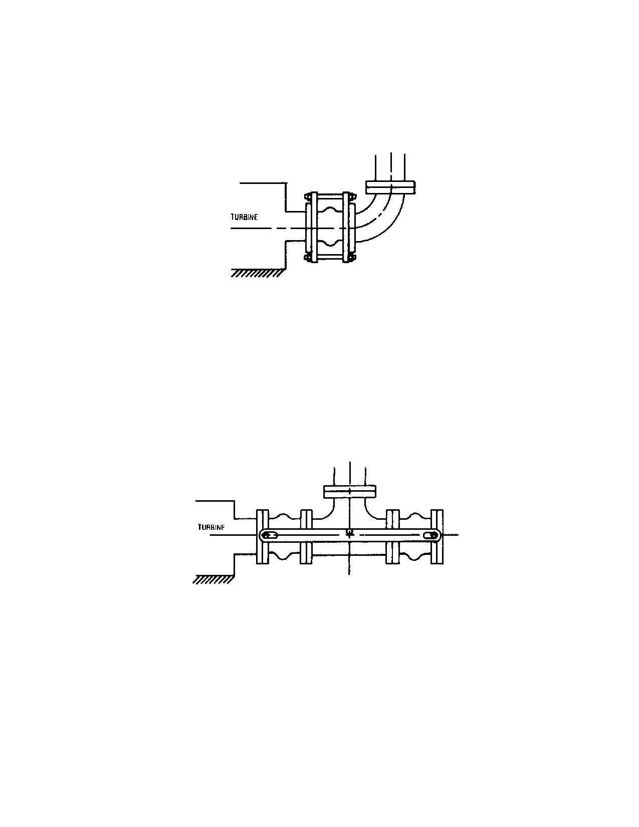
SST Turbine Instruction Manual
Speed Control System
Figure C-3 Expansion Joint with Tie Rods (Acceptable) below shows the same
piping arrangement as in the previous figure, except for the addition of tie rods on
the expansion joint.
Figure C-3. Expansion Joint with Tie Rods (Acceptable)
The tie rods limit elongation of the joint and take the axial thrust created by the
internal pressure so it is not transmitted to the turbine flange. The tie rods eliminate
any axial flexibility, but the joint is still flexible in shear, meaning that the flanges
may move in parallel planes. The location of this type of joint in the piping should
be such that movement of the pipe puts the expansion joint in shear instead of
tension or compression.
Figure C-4 Expansion Joint with Tie Rods for Non-condensing Operation
(Preferred) below is an arrangement frequently used, with tie rods as indicated.
Figure C-4. Expansion Joint w/ Tie Rods Non-Condensing Operation (Preferred)
This arrangement will prevent any thrust, due to internal pressure, from being
transmitted to the exhaust flange. It retains the axial flexibility of the joint and may
be used for either vacuum or pressure service.
SST Turbine Instruction Manual
Revision A
75
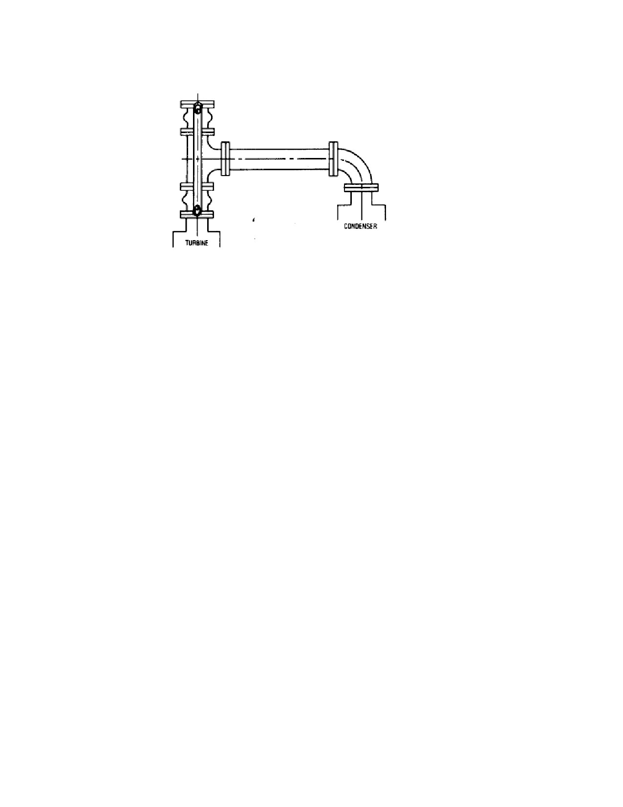
Installation
SST Turbine Instruction Manual
Figure C-5. Expansion Joint w/ Tie Rods Condensing Operation
(Preferred)
Figure C-5 shows a suggested arrangement for a condensing turbine with an up exhaust. This
arrangement is recommended and frequently used. Due to the large exhaust pipe size normally
encountered on condensing turbines, the exhaust piping will be relatively stiff and an
expansion joint must be used at some point to take care of thermal expansion. An
unrestricted expansion joint placed at the exhaust flange of the turbine will exert an upward
or lifting force on the turbine flange, which in many cases is excessive. Figure C-5
provides the necessary flexibility to take care of thermal expansion without imposing a
lifting force on the turbine. The expansion joint is in shear, which is the preferred use. The
relatively small vertical expansion will compress one joint and elongate the other, which
causes a small reaction only and will be well within the turbine flange limits.
On smaller and high-pressure exhaust lines it is frequently better to rely on the flexibility of
the piping than on an expansion joint. Only after a careful analysis of the piping shows the
need for an expansion joint should they be used.
In order to have flexibility in piping, short direct runs must be avoided. By arranging the
piping in more than one plane, torsional flexibility may be effectively used to decrease the
forces.
76
Revision A SST
Turbine
Instruction
SST Turbine Instruction Manual
Speed Control System
Figure C-6. Short Runs to Exhaust Header
Figure C-6 shows a short direct run to an exhaust header. If the header is free to float in
a horizontal plane, thermal expansion of the exhaust line will put very little direct
thrust on the exhaust flange. If the header is fixed, the thermal expansion will tend to cause
either the turbine or header to move and may cause damage. If thermal expansion causes
the header to move in an axial direction it will transmit a force and moment to the exhaust
flange. Figure C-6 is not recommended, as it is difficult to prevent excessive forces
from being transmitted to the exhaust flange.
C.3.10
Leak-Off Piping
WARNINGS
Leak-off and drain connections of turbines operated on
flammable or noxious gas must be piped to a safe location to
avoid the possibility of ignition of the gas or poisoning of
operating personnel.
LEAK-OFF AND DRAIN LINES MUST NOT BE
INTERCONNECTED. A leak-off from a high pressure upstream
location connected to a steam chest drain or throttle valve leak-
off/drain could supply sufficient steam TO ALLOW THE
TRIPPED TURBINE TO CONTINUE RUNNING, since such an
interconnection would bypass the overspeed trip valve.
SST Turbine Instruction Manual
Revision A
77
Installation
SST Turbine Instruction Manual
LEAK-OFF PIPES that are left UNCONNECTED will allow the
escape of HIGH TEMPERTURE STEAM that could cause
PERSONAL INJURY or contamination of lubricating oil.
Standard SST Dresser-Rand turbines are supplied with leak-off connections at the
gland housings, throttle valve, and overspeed trip valve. Leak-offs are piping
connections that allow steam leaking past seals to be carried away to a safe area.
Shaft and valve stem seals depend on some leakage for lubrication and to minimize
wear. Leakage is therefore acceptable and necessary.
The leak-offs must be pitched down and away from the turbine and connected to
open, unrestricted, separate, non-manifolded drain lines, which discharge to a safe
and visible area. There should not be any valves on leak-off lines. Leak-off piping
should be arranged to insure that no pressure build-up occurs in the system,
avoiding any low points where condensate could accumulate and may be connected
to a gland condenser, eductor or ejector. No vertical upward pipe runs are to be
included in leak-off piping. Unavoidable low points should be trapped.
On gas operated turbines, leak-offs must be piped to a safe area away from the
turbine site.
Locations and sizes of leak-off connections are shown on the certified drawing in
Appendix A.
Gland housings on turbines operating with vacuum exhaust or at high back pressure
require special Gland Seal leak-off systems.
For turbines operating with vacuum exhaust refer to Section C.3.11 Gland Seal
Leak-Off Piping-Vacuum Exhaust
Turbines operating with high back pressure may have intermediate leak-off
connections on their gland housings. Refer to Section C.3.12 Gland Seal
Intermediate Leak-Off Piping - High Back pressure Exhaust.
C.3.11
Gland Seal Leak-Off Piping - Vacuum Exhaust
On turbines exhausting to a vacuum, sealing steam at 5 to 10 PSIG (34 to 69 kPag)
pressures must be furnished through the carbon ring glands to prevent air from
entering the exhaust casing.
78
Revision A SST
Turbine
Instruction
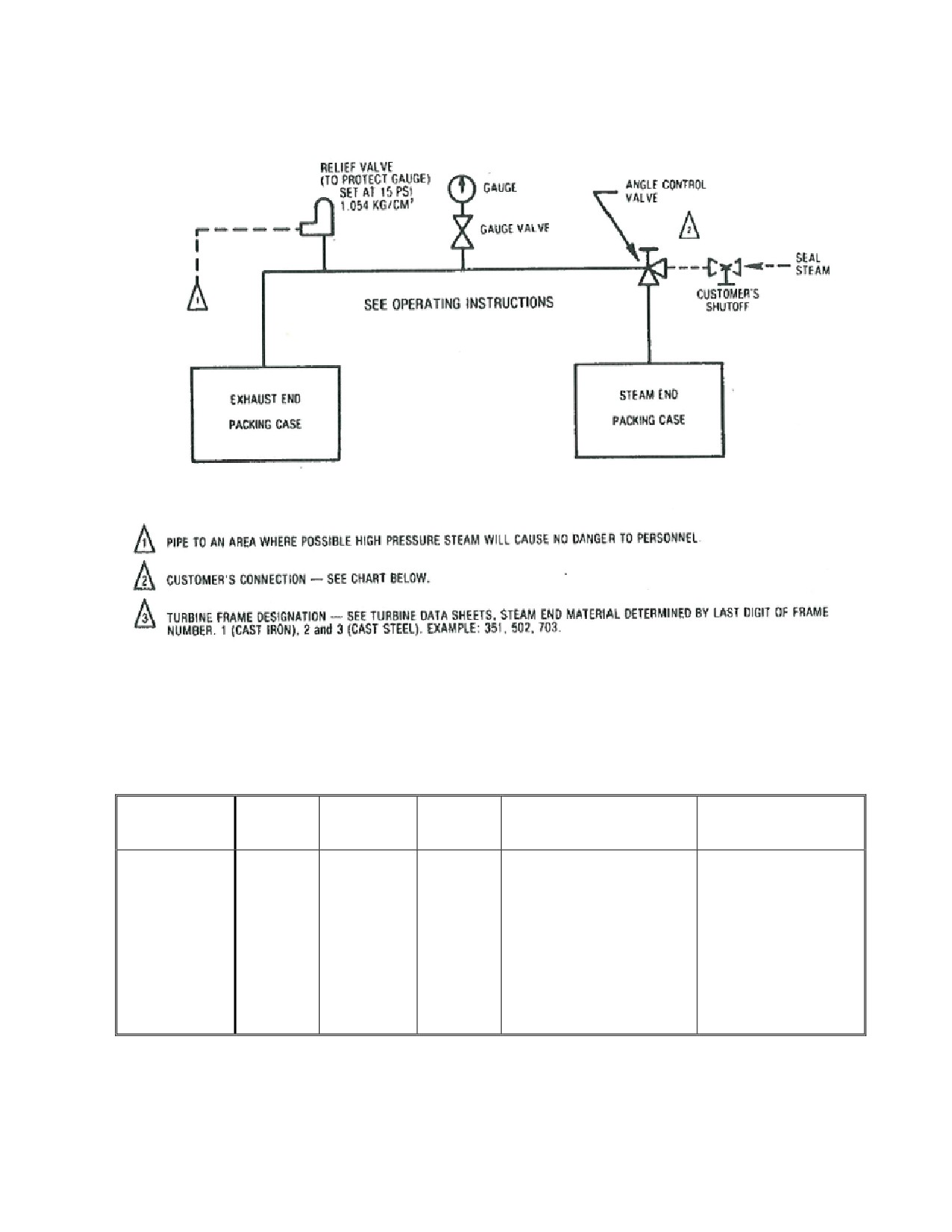
SST Turbine Instruction Manual
Speed Control System
Figure C-7. Typical Gland Sealing System without Gland Condenser
If gland seal piping is not furnished with the turbine, sealing steam connections
should be piped via a common connection to the user’s steam supply. A
recommended piping diagram for gland seal piping is shown in Figure C-6 Gland
Seal Leak-Off Piping - Vacuum Exhaust.
Frame
Relief
Gauge
Customer’s
Gauge
Angle Control Valve
Composition
Valve
Valve
Connection
Ashcroft
Kunkle
No. 1009
1/2” pipe 12.7 mm
Cat.
KGSC
Max. Press. 600
Vogt No. 1971 3/8”
Range 30”
Vogt No
Fig. No.
lbs. 750F 42.18
All Sizes
600 lbs. Steel 9.52 mm
to 30 lbs.
9871
40R
Kg/Cm2 399C
272 Kg.
760 mm to
Stainless
2.109
Steel
Kg/Cm2
Table C-1. Gland Intermediate Leak-Off Piping—High Back Pressure
Exhaust
SST Turbine Instruction Manual
Revision A
79
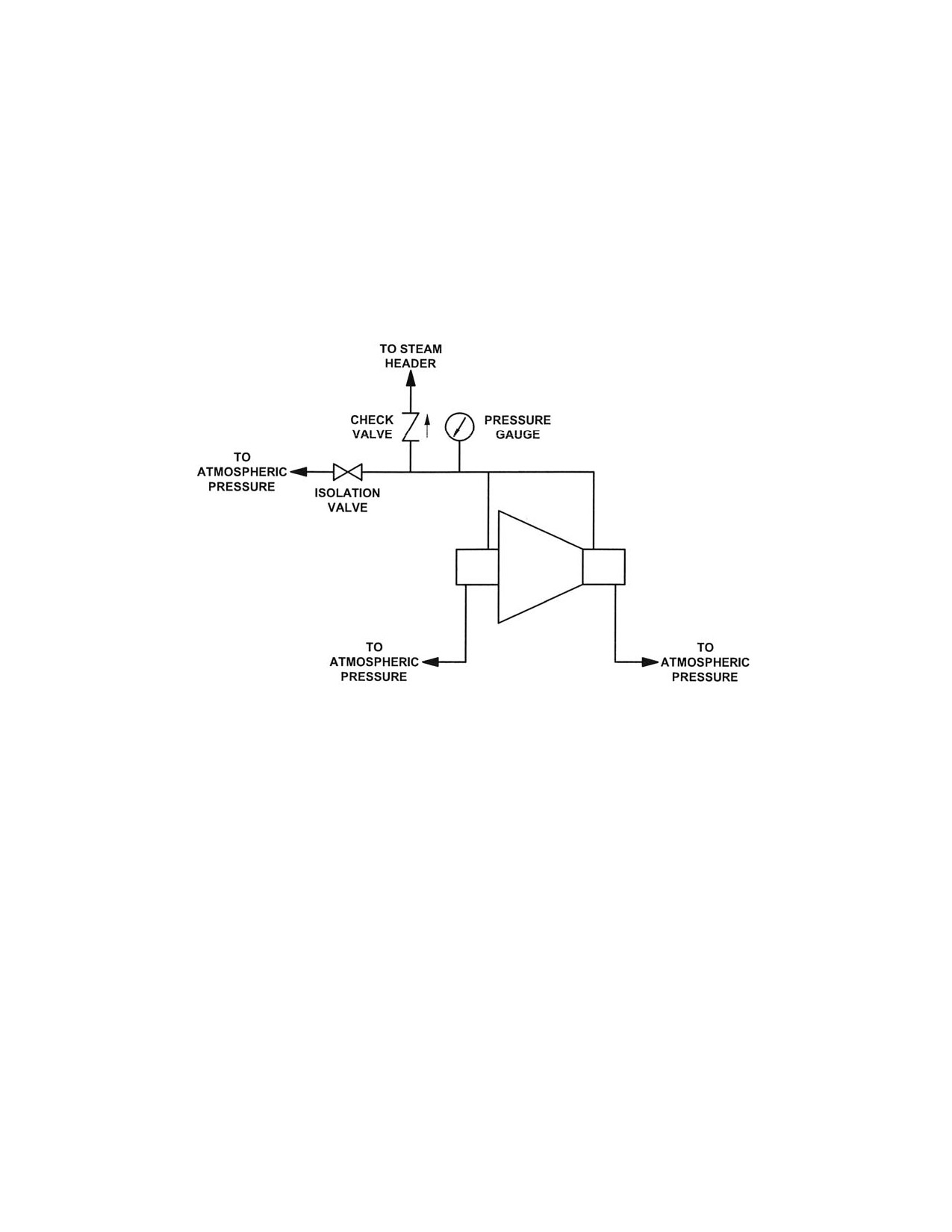
Installation
SST Turbine Instruction Manual
Turbines to be operated with high back pressure may have intermediate gland leak-
offs that must be piped to a steam header with a pressure not less than 35 PSIG
(241 kPag) and not exceeding 70 PSIG (483 kPag). This intermediate leak-off
piping must include, for start up purposes, an atmospheric vent with a shut off
valve near the turbine and a check valve installed between the vent and the steam
header to prevent back-flow. Do not connect the intermediate leak-off piping with
other leak-off connections. Refer to Figure C-8 Gland Seal Int. Leak-Off Piping
High Back Pressure Exhaust.
Figure C-8. Gland Seal Intermediate Leak-Off Piping-High Back Pressure
Exhaust
C.3.12 Gland Seal Intermediate Leak-Off Piping—High Back Pressure Exhaust
In certain turbines with a high exhaust back pressure, a gland leak-off system is used. Figure 8
shows a typical system using gland ejectors connected to the leak-off piping of both packing
cases. The ejectors maintain a constant vacuum in the gland packing case leak-off lines. When
the ejectors are shipped separate from the turbine, the piping leak-off connections from the
turbine are shown on the outline drawing, Appendix A. If gland ejectors are required for your
turbine, the specific part number is listed on the Appendix A contents sheet. On certain designs,
a drip drain connection is located adjacent to gland leak-off on each packing case. These drain
connections must be plugged.
For leak-off systems that use a gland condenser, a system schematic diagram with operating
instructions is included in Appendix A, along with a description of the major components that
comprise the system.
80
Revision A SST
Turbine
Instruction
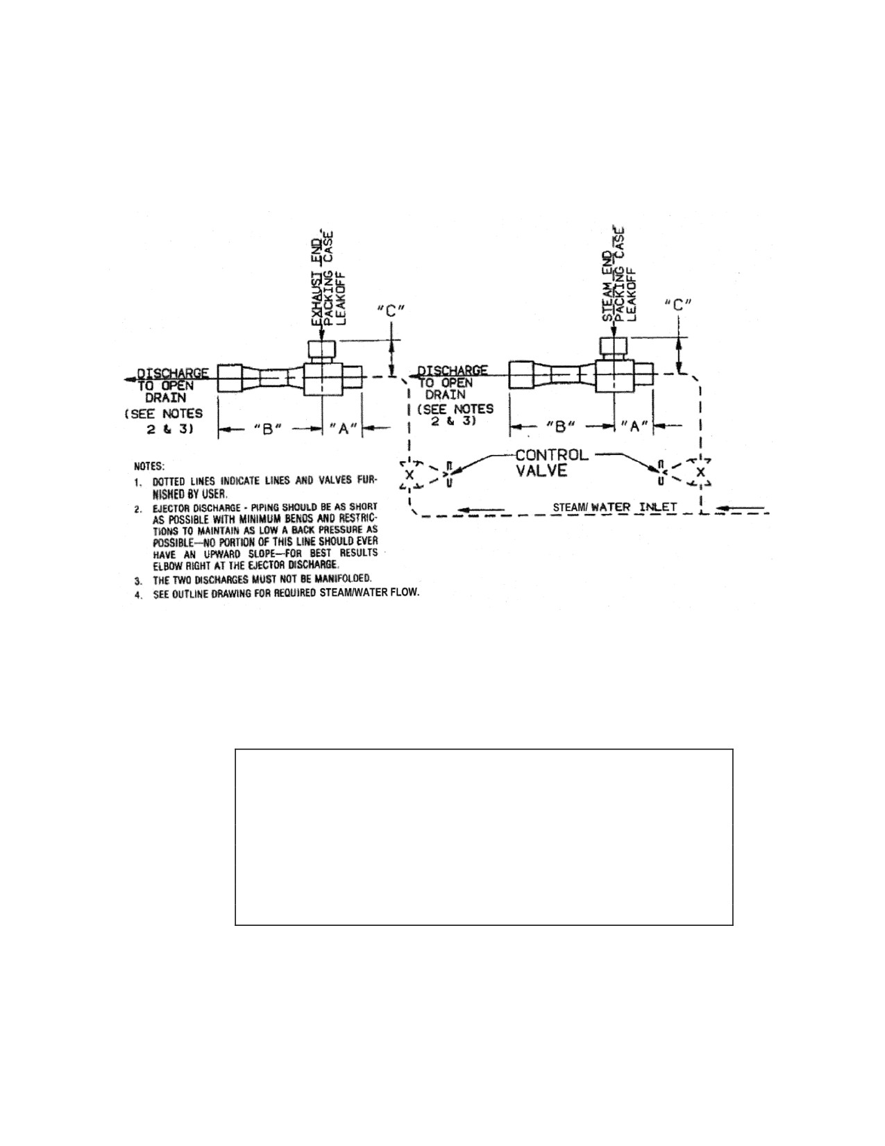
SST Turbine Instruction Manual
Speed Control System
Figure C-9. Gland Leakage Ejector System
C.3.13
Drain Piping
WARNING
DRAIN PIPING flanges and valves must be SELECTED AND
INSTALLED BY EXPERIENCED PERSONNEL, taking into
account the MAXIMUM OPERATING STEAM PRESSURE
AND TEMPERATURE. Improperly designed or installed drain
systems could FREEZE, become PLUGGED AND RUPTURE,
causing serious personal injury or equipment damage.
SST Turbine Instruction Manual
Revision A
81
Installation
SST Turbine Instruction Manual
Leak-off and drain connections of turbines operated on
flammable or noxious gas must be piped to a safe location to
avoid the possibility of ignition of the gas or poisoning of
operating personnel.
LEAK-OFF AND DRAIN LINES MUST NOT BE
INTERCONNECTED. A leak-off from a high pressure
upstream location connected to a steam chest drain or throttle
valve leak-off/drain could supply sufficient steam TO ALLOW
THE TRIPPED TURBINE TO CONTINUE RUNNING, since
such an interconnection would bypass the over-speed trip
valve.
Drains are low-point piping connections at valves and casings that allow release of
condensed water. Drains are opened before starting the turbine, to allow any
accumulated water to escape. They are left open during the start-up cycle to allow
water condensing in the cold casings to exit. Once the turbine reaches normal
operating temperature, drains should be closed.
The user must install drain valves when not supplied by Dresser-Rand.
Drains can be automated with properly sized steam traps, if desired. Refer to C-10
Suggested Steam Inlet, Exhaust and Drain Piping, Manual Start and Figure C-11
Suggested Inlet, Exhaust and Drain Piping, - Auto Start.
Sizes and locations of drains are shown on the certified drawing in the
Supplemental Documentation section, supplied at the end of this manual.
C.3.14
Water Cooling Piping to Bearing Housing Water Jackets
Depending on service conditions and the type of lubrication system supplied with
the turbine, bearing housings may require water cooling to maintain an acceptable
bearing oil temperature.
Refer to Section F, Lubrication, for cooling water application requirements,
suggested piping, water flow, pressure and temperature requirements, and oil sump
temperature.
82
Revision A SST
Turbine
Instruction
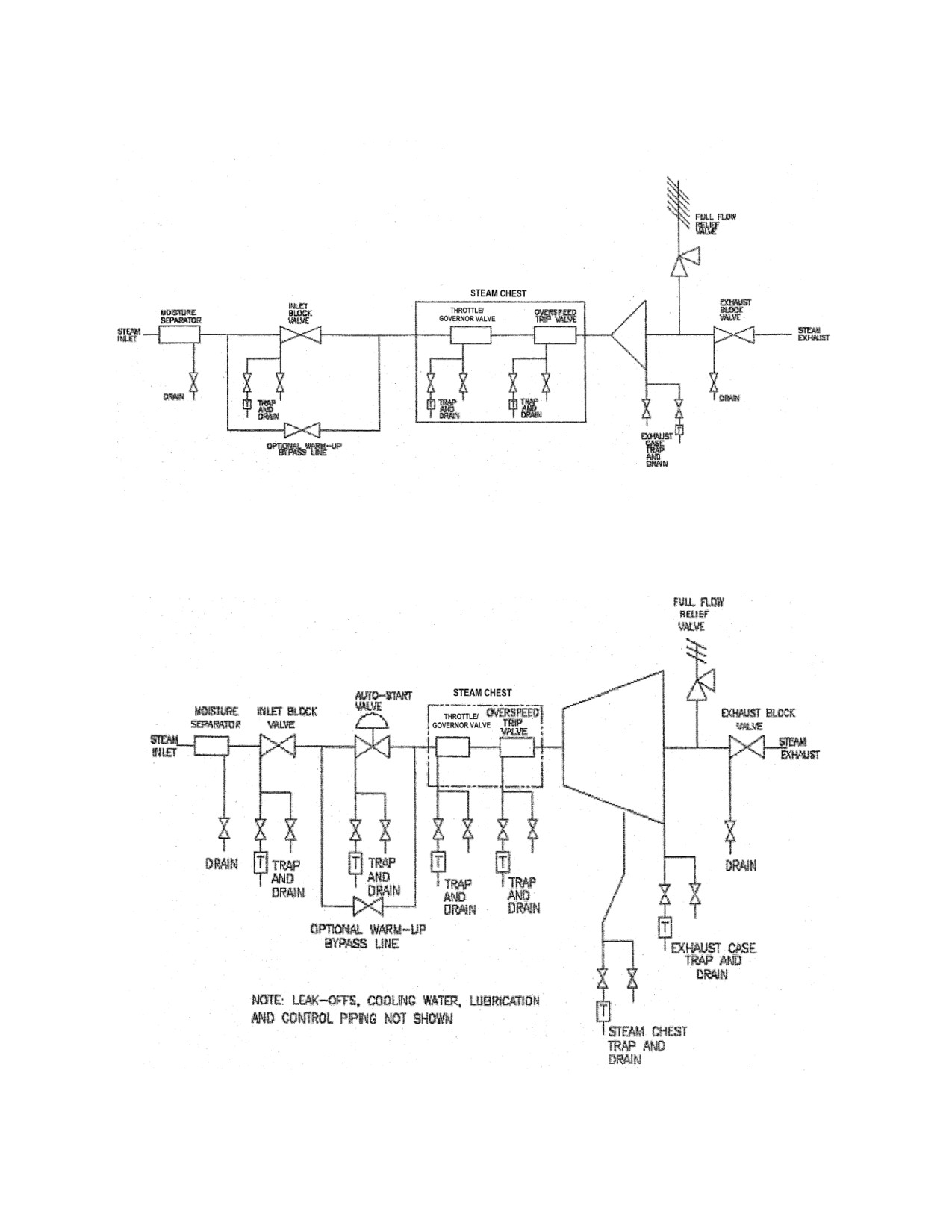
SST Turbine Instruction Manual
Speed Control System
Figure C-10. Suggested Steam Inlet, Exhaust and Drain Piping, Manual Start
Figure C-11. Suggested Steam Inlet, Exhaust and Drain Piping, Auto-Start
SST Turbine Instruction Manual
Revision A
83
Installation
SST Turbine Instruction Manual
C.4
Alignment Requirements
Many problems experienced with turbines, gears, and driven equipment is due to
misalignment. Units must be properly supported and their alignment accurately and
permanently established if the installation is to be successful.
WARNING
Misalignment with driven equipment or overload due to driven
equipment could result in excessive wear and bearing failure.
This could create sparks or hot surfaces could ignite lubricant
or flammable gasses.
CAUTIONS
ALIGNMENTS performed by the factory on turbines with gears
or other driven equipment mounted on base plates MAY SHIFT
during rigging or shipment. These alignments must be
RECHECKED before startup.
Never put a steam turbine into service without first carefully
ALIGNING it to the driven equipment under cold conditions and
then again at operating temperature. Failure to do so may
result in premature FAILURE of both TURBINE and DRIVEN
EQUIPMENT components.
Excessive vibration, bearing edge loading, and high shaft loads can result from
incorrect alignment. Factors affecting alignment can be settling of the foundation,
growth in shaft heights due to temperature changes, machine movement of either
unit with respect to the foundation due to vibration, worn bearings, or distortion of
the casing due to loads from connecting structures (such as piping). A dependable
turbine drive system requires that all of these factors be given proper attention prior
to and during alignment.
The turbine and driven equipment should always be aligned cold, checked later at
operating temperature, and re-aligned if necessary. Both shafts should be parallel
and their axes concentric so that there is no offset at operating temperature.
Two types of misalignment must be identified and corrected (if necessary) to be
within defined limits.
84
Revision A SST
Turbine
Instruction
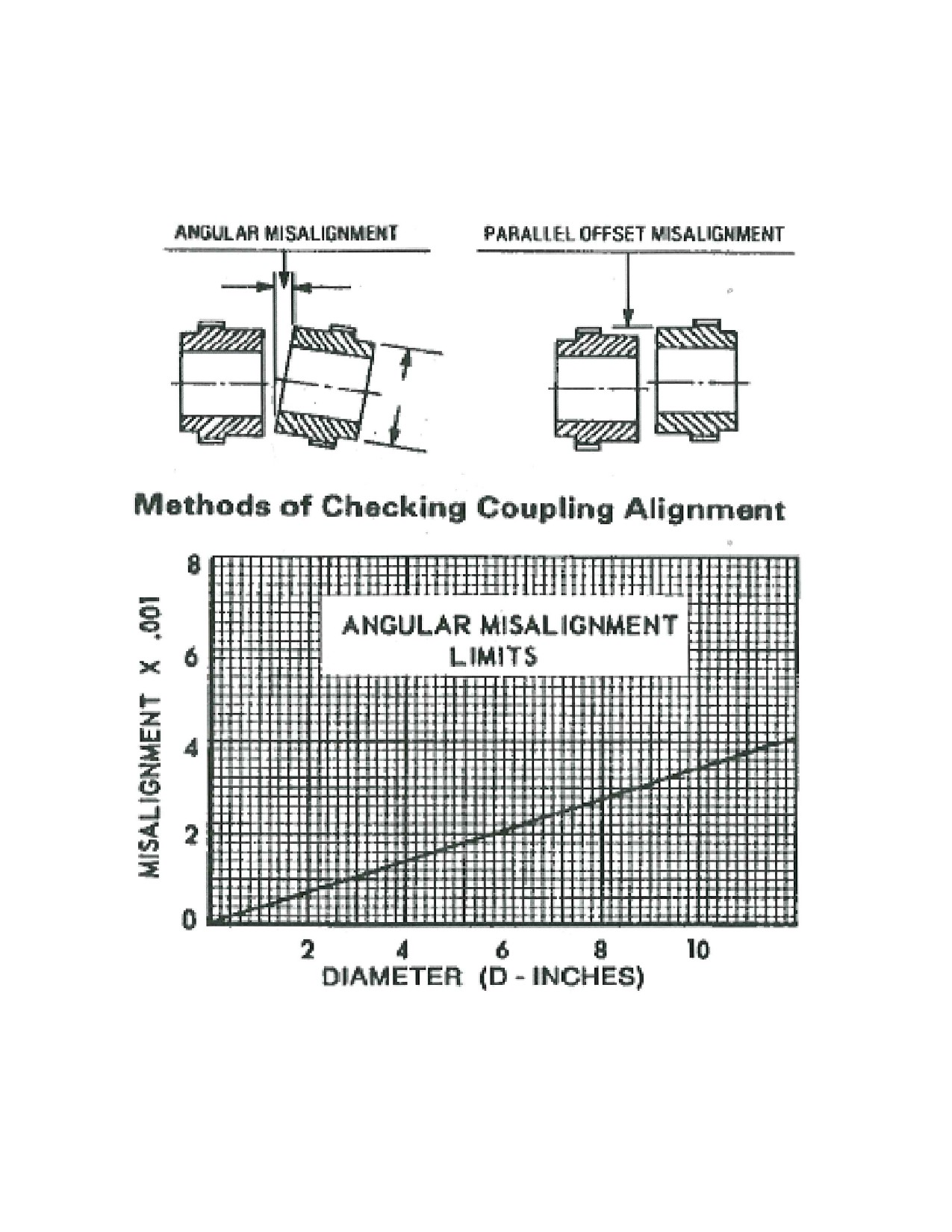
SST Turbine Instruction Manual
Speed Control System
Angular misalignment occurs when shaft centerlines intersect at an angle.
Figure C-12 Coupling Misalignment Limits
Parallel misalignment occurs when shaft centerlines are parallel to each other, but
do not intersect.
SST Turbine Instruction Manual
Revision A
85
Installation
SST Turbine Instruction Manual
As previously noted, alignment is influenced by the thermal growth of both the
turbine and the driven equipment. This must be compensated for during cold
alignment by calculating the growth of each machine and intentionally creating a
parallel offset that will disappear when the equipment is hot.
C.5
Couplings
WARNING
A coupling guard must be installed at the coupling between the
turbine and driven equipment.
When the coupling guard is to be installed, refer to the coupling
guard manufacturer’s instructions to insure that it does not
contact the running shaft or coupling which could cause a spark
that could ignite hazardous gasses in the environment in which
the turbine is installed.
CAUTION
Coupling weights should not exceed the allowable limits on the
coupling drawing without approval from Dresser-Rand. A
heavier than allowed coupling could create a lower critical
speed, which could cause excessive vibration within the
operating range of the turbine.
A flexible coupling is required to connect the turbine to the driven machine.
Couplings should be selected based on power, speed, and characteristics of the
driven machine, using selection and balancing guidelines established by the
coupling manufacturer.
Correct installation of the coupling hubs is vital to proper operation of the turbine
and driven unit; great care must be exercised in assembling hubs onto shafts.
Before mounting a coupling, check the coupling bore and shaft diameter with a
micrometer to determine that the interference fit is as specified by the coupling
manufacturer. Also, inspect the key and keyways, making sure that the key is a
drive fit into the shaft keyway and a push fit into the coupling hub keyway. The
86
Revision A SST
Turbine
Instruction
SST Turbine Instruction Manual
Speed Control System
key should also sit positively on the bottom of the shaft keyway, with clearance on
the top of the key to allow expansion within the hub keyway.
If the shaft key extends beyond the back of the coupling hub, the key should fill the
entire keyway. The exposed portion of the key must be removed so that it is flush
with the coupling back face and must be profiled flush to the circumference of the
shaft so that only the keyway in the shaft is filled, maintaining shaft balance. When
installing coupling hubs on shafts, it is important to heat them uniformly, taking
great care to avoid overheating. A recommended method is to use an oil bath with a
temperature control or an induction heater.
When fitting the coupling onto the shaft, it is helpful to have a chamfer on the sides
and top of the key, making alignment easy with the hub keyway. Also, a temporary
block should be used, to prevent the hub from sliding too far onto the shaft.
Do not use hammers to drive coupling hubs onto the shaft, as this would damage
the coupling, shaft, or bearings. As coupling hubs are frequently used for reference
in alignment, runout or eccentricity of hubs, which may be caused by damage to the
shaft, hubs, or badly fitted keys, must be avoided.
CAUTION
DO NOT drive the coupling on or off the shaft with a HAMMER.
The force of the hammer will damage the rotor locating bearing,
resulting in internal turbine damage.
NOTE
Axial clearance between the coupling hubs and shaft end faces
should be in accordance with recommendations of the coupling
manufacturer, when shafts are in their normal running
condition.
Lubricate the coupling as required, by following the coupling manufacturer’s
instructions.
C.6
Preparation for Alignment
Use the following procedure:
SST Turbine Instruction Manual
Revision A
87
Installation
SST Turbine Instruction Manual
a.
Clean turbine mating support surfaces and mount turbine on the foundation.
b.
Do not connect the turbine to inlet and exhaust piping.
c.
Disconnect the coupling by removing the coupling spacer (if provided) and
pulling coupling sleeves away from the hub.
d.
Insert suitable shim packs between supporting surfaces of the turbine and/or
driven equipment and their respective mounting surfaces. It is important to
insert sufficient shims under the equipment so that shims can be removed to
lower either piece of equipment if required during hot final alignment. A
minimum of 1/16 inch (1.6 mm) is recommended.
e.
Level and square the turbine with respect to the driven equipment.
f.
Check for base distortion and improper shimming by placing dial indicators in
vertical and horizontal planes on the driven equipment, with the indicators
detecting turbine shaft movement. Each turbine foot anchor bolt should then be
loosened and tightened, while observing the dial indicator reading. Readings
should not exceed 0.003 in. (0.075 mm); if they are exceeded, the cause must
be determined. Repeat this procedure for driven equipment.
g.
Check that all anchor bolts (i.e., turbine, driven equipment and supports) are
tightened.
h.
Check coupling hub face runout using the following procedure:
1. Install dial indicator
(refer to Figure C-13, Alignment Using Dial
Indicators) to read a point nearest to the outside circumference on the face
of one hub.
2.
Rotate the shaft and hub on which the dial indicator is touching and record
the maximum and minimum indicator readings. Axial runout is the
difference between the two readings.
3. Re-position the dial indicator to read on the external outside diameter of
the same hub as in step 1 and measure coupling hub diametral runout, as
shown in Figure C-13, Alignment Using Dial Indicators.
4.
Rotate hub and record the maximum and minimum indicator readings.
Lateral runout is 1/2 of the difference between the two readings.
5.
Repeat steps 1 through 4 for the other coupling hub.
88
Revision A SST
Turbine
Instruction
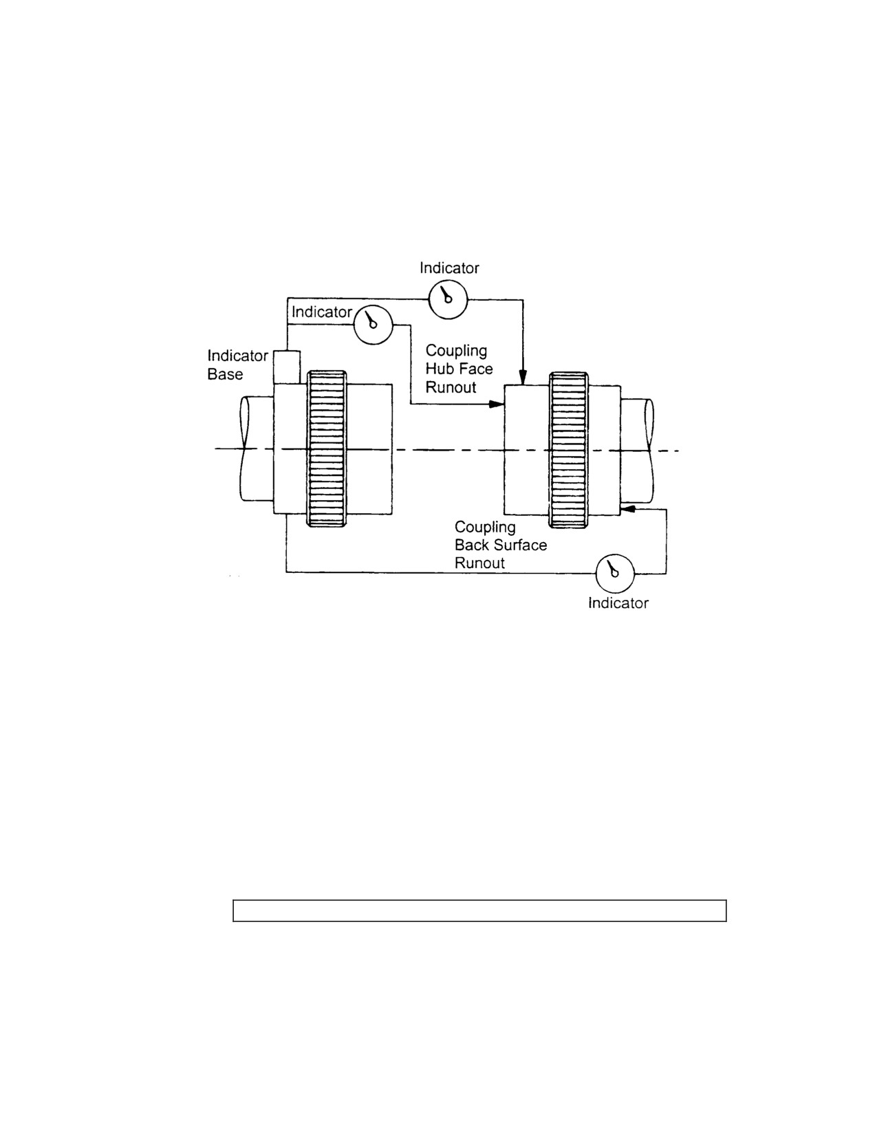
SST Turbine Instruction Manual
Speed Control System
6.
Any runout exceeding 0.0015 inch (0.038 mm) should be corrected by
reinstallation of the hub and keys or their replacement.
7. Hub runout values should be subtracted from the desired alignment
setting.
Figure C-13. Alignment Using Dial Indicators
C.7
Compensation for Thermal Movement
During initial alignment, allowances must be made for thermal expansion of the
turbine and driven equipment. The shaft centerline of each unit will rise when they
reach operating temperature. Therefore, the difference between the two anticipated
growths must be incorporated into the cold alignments so that the shafts will come
into alignment when operating temperature is attained.
CAUTION
SST Turbine Instruction Manual
Revision A
89
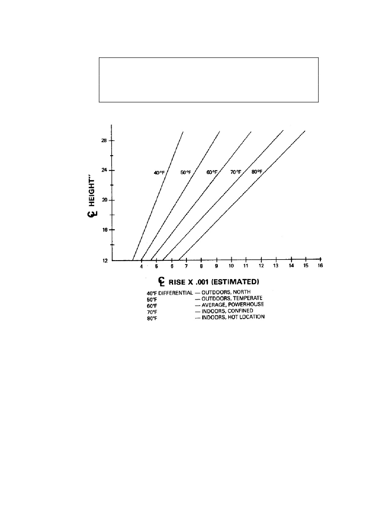
Installation
SST Turbine Instruction Manual
Thermal movement varies significantly with inlet temperature,
load, ambient conditions and time. Final hot alignment of the
turbine to the driven equipment must be based on actual
measured shaft rise under steady state conditions (after at least
a two hour run time).
Figure C-14. Centerline Height VS Centerline Rise per Ambient
Temperatures
On steam turbines, steam temperatures and insulation of the turbine case, proximity
of packing leak-off lines to the supports and type of lagging enclosure affect the
support temperatures. The average support temperatures may vary from 130F to
160 F (approximate oil drain temperatures). Judgment will have to be exercised in
estimating the support temperature for the initial cold alignment. The curves in
figure C-14 may be useful for checking and also for telling the effect of an error in
the estimate of support temperature. Refer to the certified drawings in Appendix A
for the estimated thermal movement of the turbine shaft extension.
90
Revision A SST
Turbine
Instruction
SST Turbine Instruction Manual
Speed Control System
Thermal growth of the driven equipment, or its temperature change, must be
obtained from the driven equipment manufacturer.
The unit with the greater thermal growth must be set lower than the other unit, by
the difference between their thermal growths. Normally, the turbine has the greater
thermal growth.
CAUTION
The initial alignment established with this estimated thermal
growth is only approximate. An actual hot alignment must be
performed prior to putting the turbine into service.
C.8
Cold Alignment Check
Cold alignment must be completed at ambient temperature (turbine and driven
machine in cold condition) and in the proper sequence, with angular misalignment
corrected first, followed by correction of parallel misalignment.
C.8.1
Angular Alignment
Use the following procedure:
a. Clamp a dial indicator to one coupling hub and place the finger (contact point)
against the finished face of the other hub, as shown in Figure C-13, Alignment
Using Dial Indicators.
b. Scribe a reference mark on the coupling hub at the point where the finger
touches the hub face.
c. Rotate both shafts simultaneously (in the direction they were designed to
operate), keeping the finger against the reference mark on the coupling hub.
Note the dial indicator reading at each one-quarter revolution.
d. Angular misalignment of the shafts must not exceed the coupling
manufacturer’s recommendations or a total indicator reading of 0.001 inch
(0.025 mm) for each radial inch of the coupling hub.
e. When the distance between coupling hubs does not permit the use of dial
indicators, angular misalignment can be established using one of the two
following methods:
SST Turbine Instruction Manual
Revision A
91
Installation
SST Turbine Instruction Manual
1.
Use feeler gauges to determine the gap between coupling faces at four
locations, 90 apart. Adjust the turbine or driven equipment to obtain
equal clearance within 0.001 inch (0.025 mm) between coupling faces at
each 90 location.
2.
Use a dial indicator mounted on a flexible arm to measure run-out on the
back surface of the coupling hub, as shown in Figure C-13, Alignment
Using Dial Indicators.
C.8.2
Parallel Alignment
Use the following procedure:
a.
Mark both hub rims so that their relative positions can be maintained at all
times during the alignment check.
b.
Mount the dial indicator on one of the coupling hubs and position the indicator
finger on the rim of the opposite coupling hub, as shown in Figure C-13,
Alignment Using Dial Indicators.
c.
Scribe a reference mark on the machined diameter of the coupling hub at the
point of indicator finger contact, or align match marks on the hub rims.
d.
Rotate both shafts at the same time, while retaining the indicator finger at the
reference mark and the two match points aligned.
e.
Note indicator readings at 90 locations (90, 180, 270, 360). Remember to
zero the indicator at the starting point.
f.
Repeat steps d and e two or three times to verify accuracy of readings.
In installations where there is excessive coupling gap (when a coupling spacer
is used), it may be necessary to make a reading correction when determining
vertical parallel misalignment.
g.
Parallel misalignment must not exceed the coupling manufacturer’s
recommendations or a total indicator reading of 0.002 inch (0.051 mm).
When parallel alignment is complete, connect inlet and exhaust piping, and recheck
angular and parallel alignment thoroughly.
C.8.3
If using laser alignment tooling such as Rotalign, you can eliminate Section C.B.1
and C.B.2. Follow recommended instructions included in the laser alignment
tooling.
92
Revision A SST
Turbine
Instruction
SST Turbine Instruction Manual
Speed Control System
C.9
Grouting
When cold alignment is satisfactory (the turbine has been leveled, and the coupling
alignment has been checked), grout the base plate or sole plate to the foundation
using the guidelines specified below. (Epoxy grout procedures may differ--follow
manufacturer’s instructions.)
Mix a test batch of ready-to-use grouting material to verify that the material
overcomes settlement and drying shrinkage. This type of material is normally used
for clearances less than one inch in thickness, and where the size and shape of the
space make placement difficult.
Coarse aggregate is normally used for clearances over one inch
(2.5 cm) in
thickness, where free passage of the grout will not be obstructed. One part of pea
gravel or pea stone may be added to two parts of the ready-to-use grouting material
to form coarse aggregate grout.
CAUTION
Do not disturb alignment by removing shims or wedges under
the base plate or sole plate.
Grouting must be done with all steam and exhaust piping disconnected from the
turbine.
When prepared grout mixes are used, follow the manufacturer’s instructions and
applicable safety precautions. Be sure that there are no air pockets in the grouting.
A suitable form should be built around the base-plate or sole plate before grout is
applied.
With either of the above-described mixes, use the minimum amount of water
required to create a flowable grout that completely fills the required space.
Excessive water causes segregation and bleeding.
Apply grout quickly and continuously to avoid the undesirable effects from
overworking.
Once the grout has acquired its initial set, all exposed edges should be cut off
vertically to coincide with the base-plate. Paint the grout with waterproof paint
after the grout has thoroughly dried, or apply plaster with Portland cement-sand
mortar.
Do not connect the piping before the grout is thoroughly dry and
alignment has been rechecked.
SST Turbine Instruction Manual
Revision A
93
Installation
SST Turbine Instruction Manual
C.10
Hot Alignment Check
After installation is complete, the grout is fully set, and the tightness of all hold-
down bolts have been checked, bring the turbine and driven machine up to
operating temperature (this normally takes about two hours run time), shut down
the unit, and make a careful and final check of the alignment using the procedure
outlined in Section C.8. This should be done as soon as possible after shut down, to
avoid erroneous readings due to cooling. Final adjustments should be made so that
both shafts are parallel and their axes concentric, resulting in zero offset at
operating temperature, consistent with the coupling manufacturer’s limits.
If the alignment is not satisfactory, check the following for possible causes:
a. Pipe strains distorting or shifting machines due to thermal growth (disconnect
piping and re-check alignment).
b. Springing of the base-plate or sole-plates by heat from the turbine, from a heat
source close to the turbine, or due to soft shims or partial shims.
c. Loose hold-down bolts.
d. Shifting of the entire structure due to variable loading, a change in the
foundation due to concrete curing, or improper grouting causing non-continuous
support.
When final alignment is satisfactory, dowel the turbine and driven equipment in
place to maintain proper alignment.
C.11
Fire Protection
All possible precautions should be exercised to avoid fire hazard to operating
personnel and equipment, particularly to the oil system. To guard against the event
of a serious fire around the turbine, the following protective features should be
provided at an accessible location near the unit.
Fire Extinguishing Equipment Type Best Suited for Oil Fires
Examples: Carbon Dioxide Multi-purpose Dry Chemical
Provision for emptying oil reservoir quickly by draining oil to waste or distant
storage.
A shut-off valve in the steam inlet line and in the steam inlet line to the turbo
auxiliary oil pump (if supplied).
94
Revision A SST
Turbine
Instruction
SST Turbine Instruction Manual
Speed Control System
C.12
Decommissioning
WARNING
Prior to commencing the decommissioning operation, ensure
that the inlet and exhaust stop valve are shut, locked out and
tagged to eliminate the possibility of inadvertent start-up during
the decommissioning operation.
The decommissioning procedure is as follows:
1.
Remove bolts from the inlet and exhaust flanges.
2.
Disconnect all turbine piping from permanently installed piping.
3.
Drain oil from the bearing housings and the governor. Dispose of the oil
in an environmentally responsible manner.
4.
Drain cooling water from the cooling system and bearing housings.
5.
Remove carbon rings, springs and stops from the gland housings.
6.
Remove coupling guard.
7.
Disconnect drive half coupling from driven half coupling. Remove
spacer coupling if one is installed.
8.
Remove hold down bolts/nuts from the base-plate.
9.
Sling the turbine and move it to a position where the inlet and exhaust
are exposed.
10.
Spray the internals with a rust preventative through all available
openings.
11.
Coat the non-painted machined surfaces with a water-soluble rust
preventative.
Seal all flanged connections with a rubber gasket, steel plate and through-bolts and
nuts.
Move the turbine to the selected storage location suitable for this type of
machinery.
SST Turbine Instruction Manual
Revision A
95
Speed Control System
SST Turbine Instruction Manual
Section D
Speed Control System
D.1
General
Your Dresser-Rand turbine has been designed to produce the rated power, at its
rated speed, under the specified steam conditions. This information can be found on
the turbine nameplate, on the turbine data sheet at the beginning of this manual, or
on the certified drawings in the Appendix A.
When the turbine has been provided with a droop-type governor (WOODWARD
TG-13 governor or similar), and the load created by the driven equipment is less
than the rated power, the turbine would tend to run faster than the rated speed.
When the load is greater than the rated power, the turbine would tend to run slower
than the rated speed. Regulating the amount of steam admitted to the turbine can
counteract these tendencies. The governor and throttle valve provide this function.
The governor senses the speed, at which the turbine is running and opens or closes
the throttle valve; accordingly to maintain the turbine at its predetermined (set)
speed.
WARNING
Never operate the turbine with the governor or governor system
disabled.
D.2
Standard Governor
The basic hydraulic governor is the Woodward TG mechanical-hydraulic speed
control governor. The governor is attached to the governor mounting housing and
couples to the turbine shaft via a flexible coupling. The governor linkage connects
the governor to the throttle valve.
96
Revision A SST
Turbine
Instruction
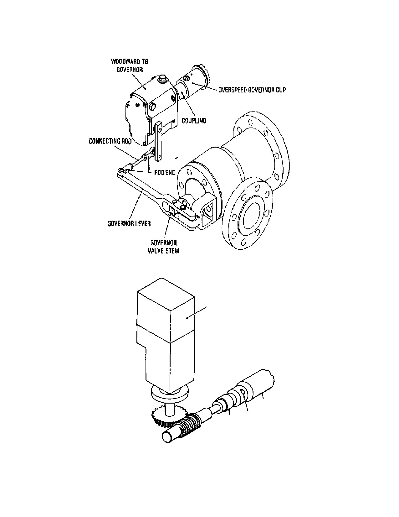
SST Turbine Instruction Manual
Speed Control System
WOODWARD
PG, UG OR 3161
GOVERNOR
TURBINE
SHAFT
OVERSPEED
COUPLING
GOVERNOR CUP
Figure D-1.
Throttle Valve Features
SST Turbine Instruction Manual
Revision A
97
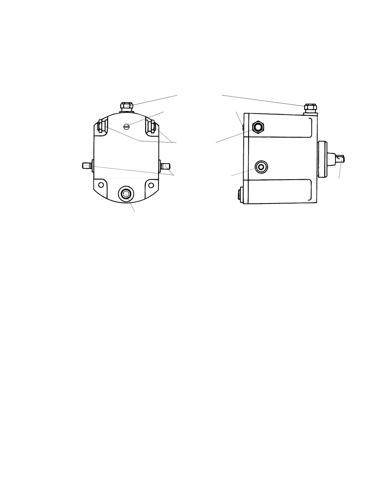
Speed Control System
SST Turbine Instruction Manual
BREATHER
SPEED ADJUSTING
SCREW
OIL LEVEL
INDICATOR
OUTPUT SHAFT
INPUT
SHAFT
DRAIN
Figure D-2. Woodward Oil Relay Governor Features
The instruction manual for the standard or optional governor is found in Appendix
B.
Figure D-2 shows external features of the Woodward TG Governor.
Breather--this is a vent for the oil reservoir and also serves as a plug for the oil
filler hole.
Oil Level Indicator--a sight gauge on the side of the Governor for checking the oil
level.
Speed Adjusting Screw--this screw, located on the rear of the Governor, increases
the turbine speed setpoint when turned clockwise.
Output Shaft--opens and closes the Throttle Valve via the throttle linkage.
Input Shaft--is connected to turbine shaft, sensing turbine speed.
Drain Plug--oil drain on the bottom of the Governor.
98
Revision A SST
Turbine
Instruction
SST Turbine Instruction Manual
Speed Control System
D.3
Lubrication and Maintenance
The hydraulic governor has a self-contained, 1.75 quart oil reservoir. Oil level can
be checked by viewing the oil level indicator on the side of the Governor.
The turbine is shipped with the governor reservoir filled with oil. Oil level should
be checked before starting the turbine and should be maintained at the proper level.
Oil should be changed according to recommendations in the Woodward manual,
included with this manual. If oil should become contaminated, quality
turbomachinery oil is recommended. Refer to Section F, Lubrication System, for oil
selection guidelines.
WARNING
Operating the GOVERNOR with DIRTY OIL or with a LOW OIL
LEVEL can cause the Governor to MALFUNCTION, resulting in
damage to the governor and possible overspeed causing
damage to the turbine and personal injury.
Refer to the governor manual for governor oil selection guidelines and for any
additional maintenance information.
D.4
Speed Range and Droop Adjustment
The hydraulic governor speed range is preset at the factory, with the purchaser’s
specified turbine rated speed within that range. The user, within the allowable
range of the supplied governor, may vary the speed set point by turning the speed
adjusting screw on the rear of the Governor. Clockwise rotation of the speed
adjusting screw increases turbine speed.
Droop, the variation in speed from no load to full load, can affect speed stability
and may need adjustment if the turbine hunts or surges. Refer to the governor
manual for details on droop adjustment.
D.5
Optional Governors
Dresser-Rand turbines can be supplied with a variety of optional governors,
depending on customer needs. If your turbine is equipped with an optional
governor, refer to the appropriate vendor manual in the Appendix B.
WARNING
SST Turbine Instruction Manual
Revision A
99
Speed Control System
SST Turbine Instruction Manual
NEVER attempt to START the steam TURBINE without first
reading about and UNDERSTANDING the GOVERNOR
CONTROLS.
D.6
Throttle / Governor Valve
The SST throttle/governor valve (refer to Figure D-1, Throttle Valve Features)
consists of a balanced Venturi valve sliding in a cage contained within the valve
body. The valve stem extends through the valve bonnet, which contains a set of
hardened bushings. The bushings are captured in the cover, which is provided with
a leak-off to direct any steam that escapes past the stem bushings away from the
valve. Drain holes at the bottom of the steam chest are used to connect piping,
which drains condensate from the valve. The turbine is shipped with pipe plugs in
the drain holes. Refer to Section C.3.10, C.3.11, C.3.12 and C.3.13, for leak-off and
drain piping recommendations.
The throttle/governor valve needs no regular maintenance other than replacement
of the stem bushings if leakage becomes excessive. Valve stem freedom of
movement should be checked prior to starting a turbine that has been out of service
for any significant length of time.
The steam strainer screen, surrounding the throttle valve cage, prevents
foreign matter from entering the turbine. If foreign matter does appear in the steam
chest, turbine nozzles exhaust casing, or if blading is damaged, then the steam
strainer may be defective. Foreign matter that gets past an intact steam strainer
generally has a small particle size, or it could come from within the turbine itself.
Optional construction may include separate throttle and/or over-speed trip valves or
other equipment configurations. Refer to the certified drawings in Appendix A.
When a turbine is supplied without an integral or separate Y-type strainer, the
purchaser must install an appropriate steam strainer in the inlet steam piping.
100
Revision A SST
Turbine
Instruction
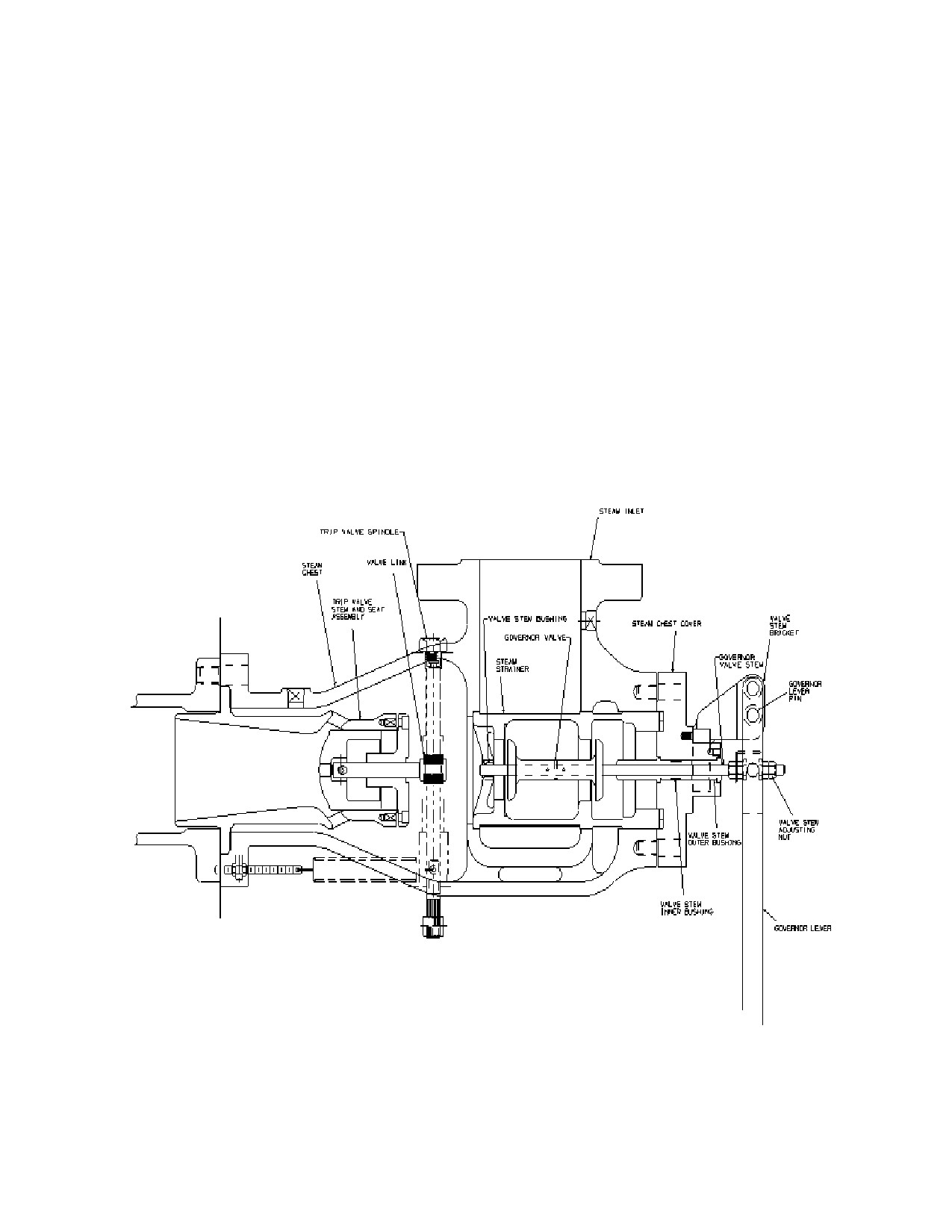
SST Turbine Instruction Manual
Speed Control System
Figure D-3. Governor Valve and Emergency Trip Valve
SST Turbine Instruction Manual
Revision A
101
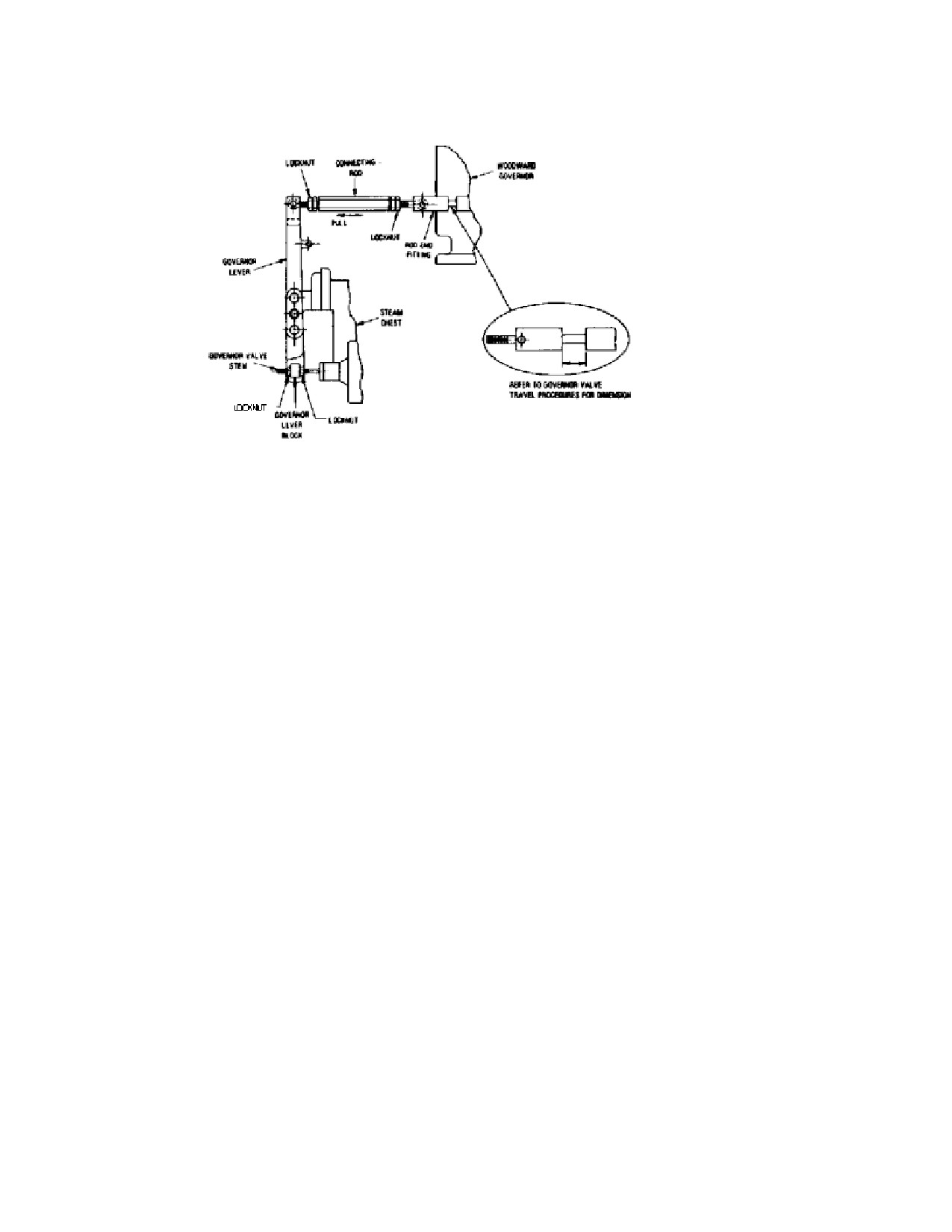
Speed Control System
SST Turbine Instruction Manual
Figure D-4. Woodward Governor Valve Linkage
D.7
Governor Linkage
The linkage between the governor and the throttle/governor valve needs no
lubrication or maintenance. However, it should be checked periodically for
freedom of movement and for worn parts.
D.8
Hand Valves
The steam turbine may be equipped with one or two optional hand-valves, located
on the steam chest. The purpose of the hand-valves is to allow the operator to open
or close passages to one or more of the turbine nozzles. Since the turbine is more
efficient when operating at the highest possible steam chest pressure, it is advised
to operate the turbine with the throttle/governor valve open as wide as possible,
while regulating power with the hand-valves. If operating at lower power is
necessary, this is accomplished by closing hand-valves one at a time until the
governor and throttle/governor valve are no longer capable of maintaining speed
(throttle/governor valve is wide open), and then opening one hand-valve. If the load
should increase while operating in this mode (more power is required), it will be
necessary to open additional hand-valves to maintain speed.
102
Revision A SST
Turbine
Instruction
//////////////////////////////////////////