THE M240G MACHINEGUNNER. Maintenance Manual MCI 0321B (2007) - page 2
Lesson 1 Exercise
Directions
Complete exercise items 1 through 6 by performing the action required.
Check your answers against those listed at the end of this study unit.
Item 1
To lower the bipod for use, push in on the ________________________ to
release the bipod.
a. bipod latch
b. slide release latch
c. bipod lever
d. slide release lever
Items 2
Matching: For items 2 through 4, match the action for setting up the M122
Through 5
tripod in column 2 with the proper step in column 1 when using the tripod.
Column 1
Column 2
Order
Action
____ 2. Step 1
a. Attach the flex-mount.
____ 3. Step 2
b. Attach the M240G.
____ 4. Step 3
c. Set up the tripod.
____ 5. Step 4
d. Prepare the T&E.
Item 6
When preparing the T&E mechanism, you manipulate the elevation hand
wheel and the traversing slide until approximately _________ inches are
exposed on both the upper and lower elevation screws.
a.
1/2
b.
1
c.
1 1/2
d.
2
Continued on next page
MCI Course 0321B
3-17
Study Unit 3, Lesson 1 Exercise
Lesson 1 Exercise, Continued
Answers
The table below lists the answers to the exercise items on the previous pages.
If you have any questions about the items, refer to the reference page.
Item Number
Answer
Reference Page
1
a
3-4
2
c
3-7
3
d
3-9
4
a
3-11
5
b
3-14
6
c
3-9
Lesson
In this lesson, you have learned how to set up the M240G using the bipod,
Summary
tripod, and a tactical vehicle mount.
In the next lesson, you will learn how to properly load and unload
ammunition from the M240G.
MCI Course 0321B
3-18
Study Unit 3, Lesson 1 Exercise
LESSON 2
LOADING AND UNLOADING
Introduction
Scope
The M240G is designed to provide a heavy, controlled volume of accurate,
continuously, and long-range fire that is beyond the capabilities of individual
small arms to suppress and destroy the enemy. To keep M240G fire
continuous, the operator must be able to load the weapon correctly in a timely
manner.
In this lesson, you will learn the weapon condition codes as they apply to the
M240G and how to properly load and unload ammunition from the M240G.
Learning
Upon completion of this lesson, you should be able to
Objectives
• Identify the weapon conditions for the M240G.
• Identify the steps for loading the M240G with the cover open.
• Identify the steps for loading the M240G with the cover closed.
• Identify the steps for unloading the M240G.
In This Lesson This lesson contains the following topics:
Topic
See Page
Introduction
3-19
Weapon Conditions
3-20
Loading
3-21
Unloading
3-22
Lesson 2 Exercise
3-23
MCI Course 0321B
3-19
Study Unit 3, Lesson 2
Weapon Conditions
Four
The table below lists and describes the four weapon conditions for the
Conditions
M240G:
Condition
Description
The bolt is locked to the rear, the safety is engaged.
1
Ammunition is on the feed tray, the cover is closed.
2
Does not apply to the M240G.
The bolt is forward, the chamber is empty, and the safety is
3
disengaged. Ammunition is on the feed tray, the cover is
closed.
The bolt is forward, the safety is disengaged, and the feed tray
4
is clear of ammunition. The cover is closed.
MCI Course 0321B
3-20
Study Unit 3, Lesson 2
Loading
Cover Opened The steps for loading the M240G with the cover opened are listed in the table
below:
Step
Description
1
Clear the weapon (condition 4).
2
Open the cover.
3
Insert the link belt into the feed tray with the open side of the
link facing down.
4
Position the first round against the cartridge stop aligning it
with the feed tray grove.
5
Close the cover, ensuring it locks shut (condition 3).
6
Pull and hold the cocking handle to the rear, ensuring the bolt
locks to the rear.
7
Place the safety on SAFE (condition 1).
8
Return the cocking handle to the forward position.
Cover Closed
The steps for loading the M240G with the cover closed are listed in the table
below:
Step
Description
1
Ensure the cover is closed, the bolt is forward, and the safety is
on FIRE.
2
Insert the link belt into the feed tray with the open side of the
link facing down.
3
Push the first round into the feedway, ensuring the first round
engages the feed pawl and is held in place (condition 3).
4
Pull and hold the cocking handle to the rear, ensuring the bolt
locks to the rear.
5
Place the safety on SAFE (condition 1).
6
Return the cocking handle to the forward position.
MCI Course 0321B
3-21
Study Unit 3, Lesson 2
Unloading
Procedure
The procedure for unloading the M240G is listed in the table below:
Step
Description
1
Pull the cocking handle to the rear, ensuring the bolt locks to
the rear. Return the cocking handle to the forward position.
2
Place the safety on SAFE (condition 1).
3
Open the cover.
4
Remove the belt of ammunition and any links from the feed
tray.
5
Raise the feed tray and inspect the chamber and receiver for
rounds or brass.
6
Lower the feed tray. The weapon is now unloaded.
Note: After the weapon is unloaded, it can be reloaded to a condition 1
weapon or cleared to make a condition 4 weapon.
MCI Course 0321B
3-22
Study Unit 3, Lesson 2
Lesson 2 Exercise
Directions
Complete exercise items 1 through 4 by performing the action required.
Check your answers against those listed at the end of this lesson.
Item 1
Name and give a brief description of the four weapon conditions for the
M240G medium machinegun.
•
____________________________________________________________
____________________________________________________________
•
____________________________________________________________
____________________________________________________________
•
____________________________________________________________
____________________________________________________________
•
____________________________________________________________
____________________________________________________________
Item 2
List the steps in order to load the M240G with the cover open.
1.
____________________________________________________________
2.
____________________________________________________________
3.
____________________________________________________________
4.
____________________________________________________________
5.
____________________________________________________________
6.
____________________________________________________________
7.
____________________________________________________________
8.
____________________________________________________________
Continued on next page
MCI Course 0321B
3-23
Study Unit 3, Lesson 2 Exercise
Lesson 2 Exercise, Continued
Item 3
List the steps in order when loading the M240G with the cover closed.
1.
____________________________________________________________
2.
____________________________________________________________
3.
____________________________________________________________
4.
____________________________________________________________
5.
____________________________________________________________
6.
____________________________________________________________
Item 4
List the steps in order when unloading the M240G.
1.
____________________________________________________________
2.
____________________________________________________________
3.
____________________________________________________________
4.
____________________________________________________________
5.
____________________________________________________________
6.
____________________________________________________________
Continued on next page
MCI Course 0321B
3-24
Study Unit 3, Lesson 2 Exercise
Lesson 2 Exercise, Continued
Answers
The table below lists the answers to the exercise items on the previous pages.
If you have any questions about the items, refer to the reference page.
Item Number
Answer
Reference Page
1
•
Condition 1. The bolt is locked to
3-20
the rear and the safety is engaged.
Ammunition is on the feed tray,
the cover is closed.
•
Condition 2 does not apply to the
M240G.
•
Condition 3. The bolt is forward,
the chamber is empty, and the
safety is disengaged. Ammunition
is on the feed tray, the cover is
closed.
•
Condition 4. The bolt is forward,
the safety is disengaged, and the
feed tray is clear of ammunition.
The cover is closed.
2
1.
Clear the weapon (condition 4).
3-21
2.
Open the cover.
3.
Place the link belt in the feed tray
with the open side of the link
facing down.
4.
Position the first round against the
cartridge stop aligning it with the
feed tray grove.
5.
Close the cover, ensuring it locks
shut (condition 3).
6.
Pull and hold the cocking handle
to the rear, ensuring the bolt locks
to the rear.
7.
Place the safety on SAFE
(condition 1).
8.
Return the cocking handle to the
forward position.
Continued on next page
MCI Course 0321B
3-25
Study Unit 3, Lesson 2 Exercise
Lesson 2 Exercise, Continued
Answers,
continued
Item Number
Answer
Reference Page
3
1.
Ensure the cover is closed, the bolt
3-21
is forward, and the safety is on
FIRE.
2.
Insert the link belt into the feed
tray with the open side of the link
facing down.
3.
Push the first round into the
feedway, ensuring the first round
engages the feed pawl and is held
in place (condition 3).
4.
Pull and hold the cocking handle
to the rear, ensuring the bolt locks
to the rear.
5.
Place the safety on SAFE
(condition 1).
6.
Return the cocking handle to the
forward position.
4
1.
Pull the cocking handleto the rear,
3-22
ensuring the bolt locks to the rear.
Return the cocking handle to the
forward position.
2.
Place the safety on SAFE
(condition 1).
3.
Open the cover.
4.
Remove the belt of ammunition
and any links from the feed tray.
5.
Raise the feed tray and inspect the
chamber and receiver for rounds
or brass.
6.
Lower the feed tray. The weapon
is now unloaded.
Lesson
In this lesson, you learned the weapon conditions as they apply to the M240G
Summary
and how to properly load and unload ammunition.
In the next lesson, you will learn how to fire the M240G.
MCI Course 0321B
3-26
Study Unit 3, Lesson 2 Exercise
LESSON 3
FIRING
Introduction
Scope
You are in your position. The M240G is mounted on the tripod with a full
belt of ammunition loaded. Now it is time to wait on the signal from the team
leader to begin engaging targets. What is next?
In this study unit, you will learn how to fire the M240G, including trigger
manipulation, sight adjustment and aiming, firing from the different mounts,
and changing the barrel.
Learning
Upon completion of this lesson, you should be able to
Objectives
• Identify trigger manipulation as it relates to rates of fire.
• Identify the use for the two position of the rear sight assembly.
• Identify the how to adjust the rear sight assembly.
• Define sight alignment.
• Define sight picture.
• Identify the guidelines when firing from the bipod.
• Identify the guidelines when firing from the tripod.
• Identify how to manipulate the traversing and elevating mechanism.
• Identify when to conduct a barrel change.
• Identify the steps for changing the barrel.
Continued on next page
MCI Course 0321B
3-27
Study Unit 3, Lesson 3
Introduction, Continued
In This Lesson This lesson contains the following topics:
Topic
See Page
Introduction
3-27
Trigger Manipulation
3-29
Adjusting the Sights
3-30
Aiming
3-32
Using the Bipod
3-33
Using the Tripod
3-34
Changing the Barrel
3-37
Lesson 3 Exercise
3-41
MCI Course 0321B
3-28
Study Unit 3, Lesson 3
Trigger Manipulation
Trigger Control The trigger on the M240G is not squeezed as with other small arms. The
trigger is pulled to the rear to allow a burst of rounds to fire. This action
allows the gunner to control the number of rounds fired to achieve different
rates of fire. Bursts of six rounds or less should not be fired as this can cause
excessive wear on the sear and sear notch.
Rates of Fire
Achieving the different rates of fire with the M240G is accomplished by
holding down the trigger for a specific round burst. The rates of fire with the
associated firing information are listed in the table below:
Rate of Fire
Rounds per Minute
Burst
Pause
Rapid
200
10-12 rounds
2-3 seconds
Sustained
100
6-8 rounds
4-5 seconds
MCI Course 0321B
3-29
Study Unit 3, Lesson 3
Adjusting the Sights
The Front Sight The front sight can be adjusted using the front sight combination tool. This
adjustment is done during the zeroing procedure, which is covered in Lesson
4, “Adjusting the Front Sight Assembly.”
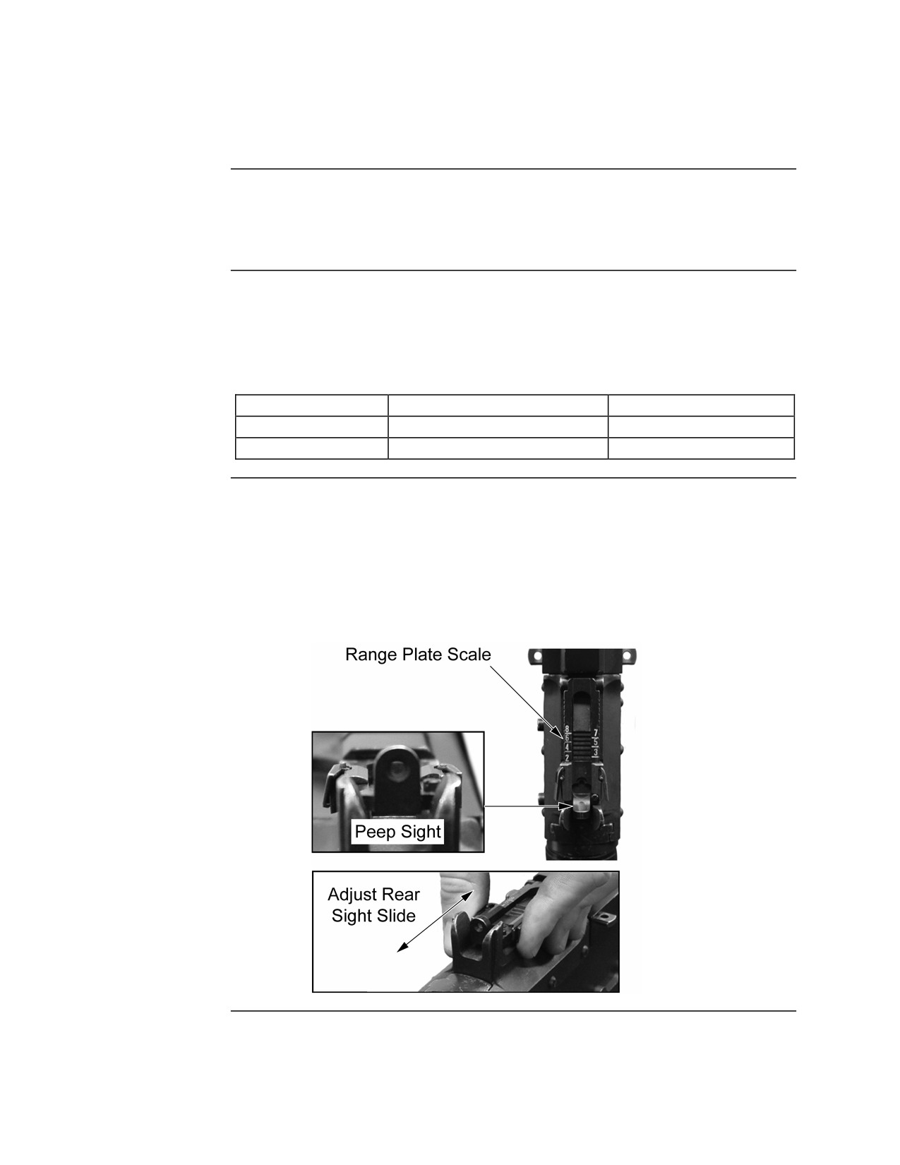
The Rear Sight The rear sight consists of a peep sight aperture on an adjustable sight leaf
slide. The sight leaf slide rides on a range plate with a graduated scale and is
attached to the receiver by a hinged plate. The rear sight has two positions—
horizontal and vertical.
Sight Position
Target Range
Used with
Horizontal
800 meters or less
Bipod or Tripod
Vertical
Greater than 800 meters
Tripod
Horizontal
In the horizontal position, the gunner can engage targets up to 800 meters.
Position
The sight is adjusted by squeezing the catches on the rear sight slide and
moving it forward or backward to the range setting on the range plate scale.
The range plate scale is marked in 100 meter increments from 200 to 800
meters. In this position, the peep sight aperture is used with the front sight
blade to aim at the target.
Continued on next page
MCI Course 0321B
3-30
Study Unit 3, Lesson 3
Adjusting the Sights, Continued
Vertical
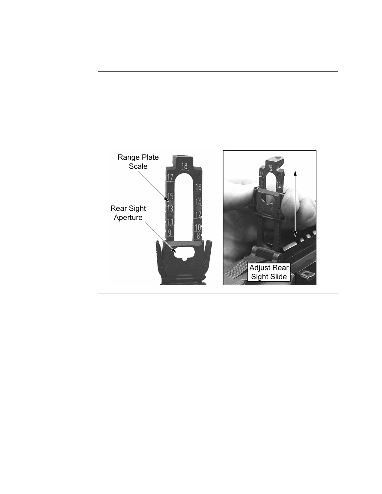
In the vertical position, the gunner can engage targets from 800 meters to
Position
1,800 meters. The sight is adjusted by squeezing the catches on the rear sight
slide and moving it up or down to the required range setting on the range
plate scale. In the vertical position, the range plate scale is marked in 100
meter increments from 800 meters to 1800 meters. In this position, the
groove in the rear sight slide and the front sight blade are used to aim at the
target.
MCI Course 0321B
3-31
Study Unit 3, Lesson 3
Aiming
Sight
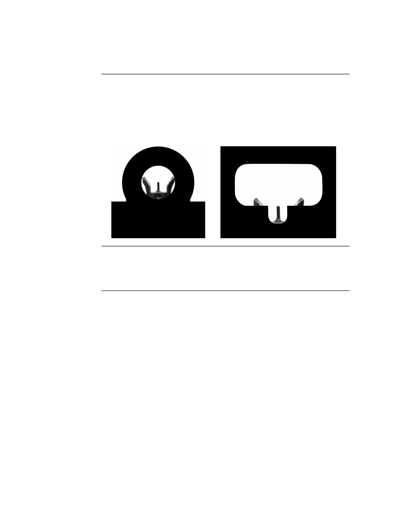
Sight alignment is the relationship between the front sight blade, the rear
Alignment
sight, and the aiming eye. When the rear sight is in the horizontal position,
obtain sight alignment by placing the tip of the front sight blade in the center
of the peep sight aperture. When the rear sight is in the vertical position,
obtain sight alignment by centering the front sight blade in the rear sight with
the tip of the front sight blade even with the bottom of the peep sight aperture.
Sight Picture
Sight picture is placing the tip of the front sight blade on the target while
maintaining sight alignment. Obtain a sight picture by centering the front
sight blade over the center of the target.
MCI Course 0321B
3-32
Study Unit 3, Lesson 3
Using the Bipod
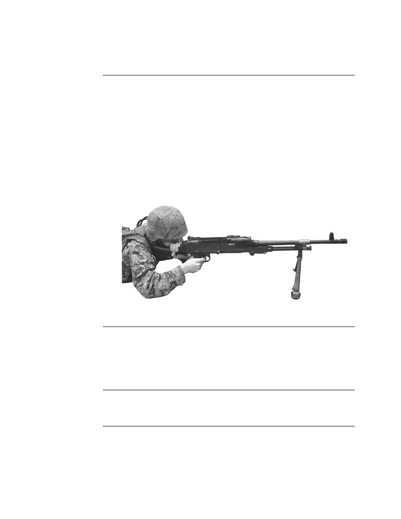
Firing Position When firing the M240G while using the bipod, follow the guidelines listed
below:
• The gunner is in a prone position behind the weapon.
• The buttplate is placed into the right shoulder.
• The right hand grasps the pistol grip and manipulates the trigger.
• The left hand is placed on the comb of the stock, palm down.
• The cheek rests lightly on the buttstock and/or left hand.
• Exert a firm pressure with both hands to the rear during aiming and firing.
• Lean forward and apply forward pressure on the bipod.
Changing
The bipod attaches to the M240G with a ball joint allowing for minor changes
Direction
in direction up to about 45 degrees. To make a minor change in the direction
of fire, the gunner will shift the shoulders and upper torso to the left or right.
To make a major change in direction, the gunner’s entire body must move
until it is realigned behind the weapon.
Changing
To make changes in elevation, the gunner will simply move the elbows closer
Elevation
together or farther apart moving the stock of the weapon up or down.
MCI Course 0321B
3-33
Study Unit 3, Lesson 3
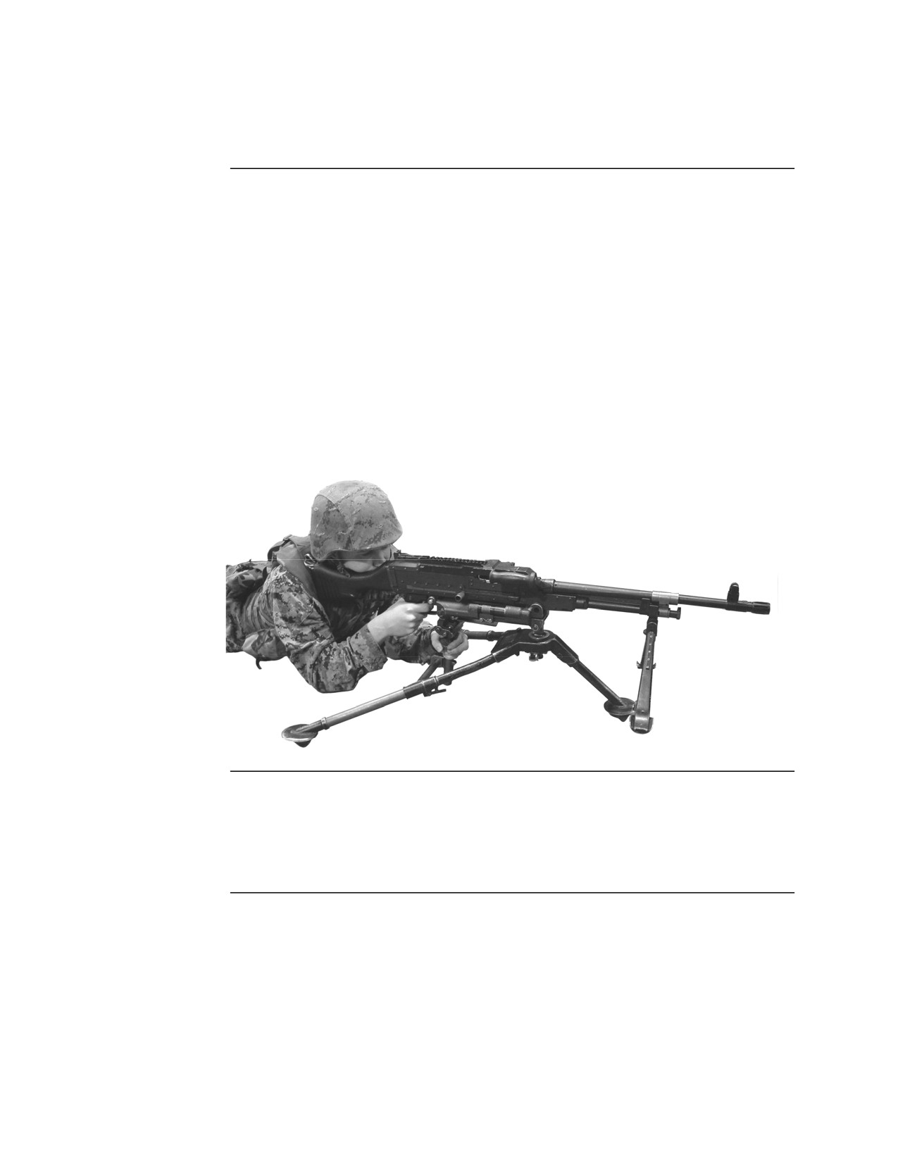
Using the Tripod
Firing Position When firing the M240G while using the tripod, follow the guidelines listed
below:
• The gunner is in a prone position behind the weapon.
• The right shoulder is placed against the buttplate.
• The right hand grasps the pistol grip and manipulates the trigger.
• The left hand is placed on the elevation hand wheel; palm down, to
manipulate the T&E mechanism.
• The cheek rests lightly on the buttstock.
• Exert a firm pressure with both hands to the rear during aiming and firing.
• Exert pressure down and to the right with the shoulder to take up the slack
in the T&E mechanism.
Orienting the
Before firing, the weapon should be adjusted so the muzzle is pointing in the
Weapon
general direction of fire. To do this, release the slide lock lever and move the
T&E mechanism to the left or right along the traversing bar. Once the
weapon is properly oriented, secure the slide lock lever.
Continued on next page
MCI Course 0321B
3-34
Study Unit 3, Lesson 3
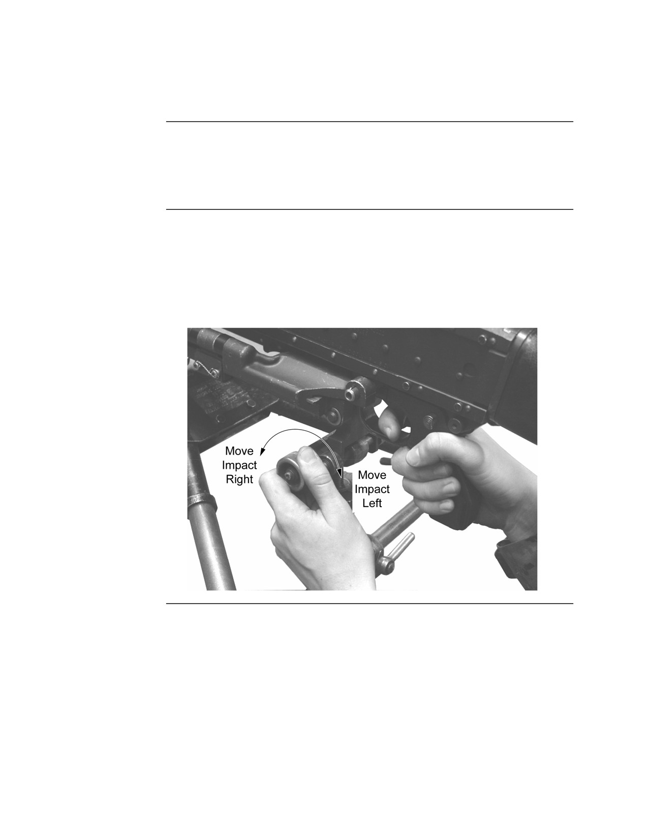
Using the Tripod, Continued
T&E
All changes to the T&E mechanism will be made with the left hand. Changes
Manipulation
in direction (traversing) will always be made first then changes in elevation.
If the situation requires rapid changes in direction and elevation that cannot
be achieved with the T&E, the weapon should be fired from the bipod.
Changing
Changing the direction is called traversing. To traverse, place the left hand
Direction
on the traversing hand wheel, thumb up. To move the impact of the rounds to
the right, push (rotate) the traversing hand wheel away from you with the
thumb—push right. To move the impact of the rounds to the left, pull
(rotate) the traversing hand wheel to the rear toward you with the thumb—
pull left.
Continued on next page
MCI Course 0321B
3-35
Study Unit 3, Lesson 3
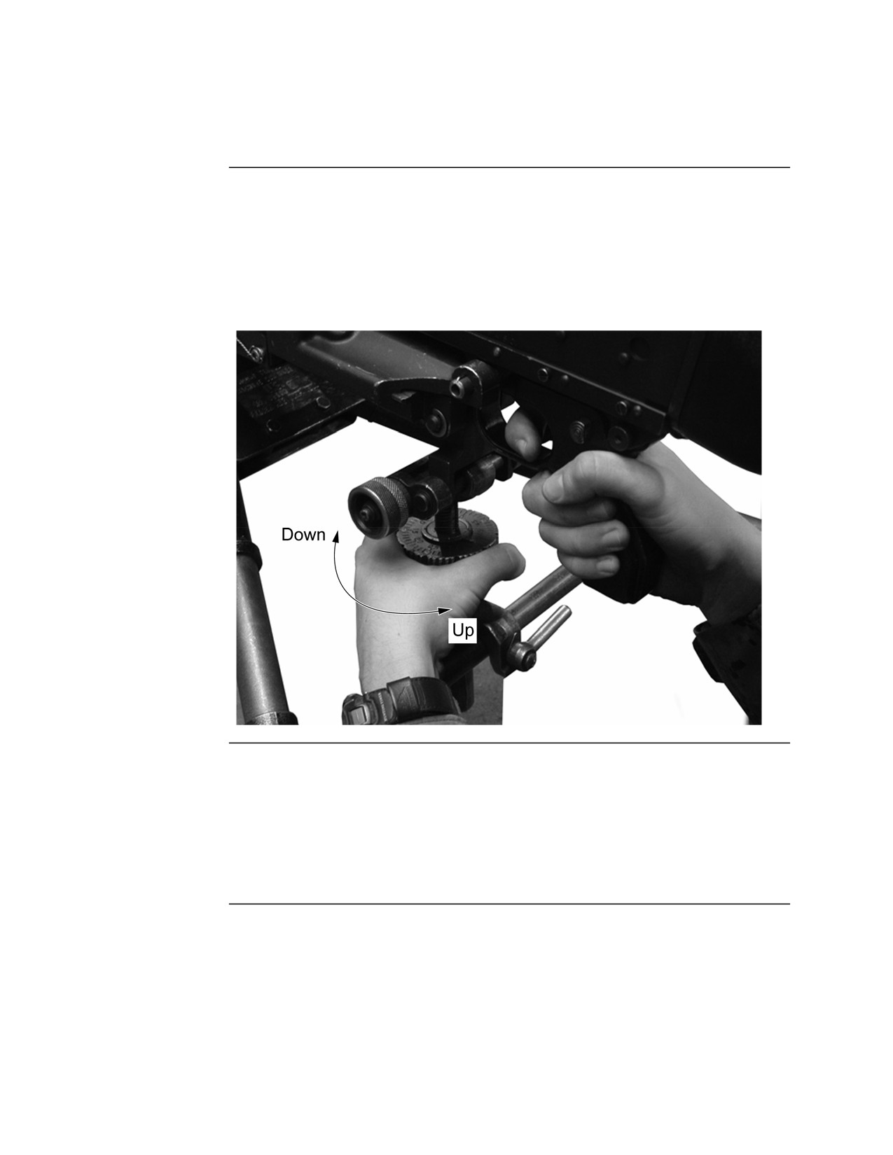
Using the Tripod, Continued
Changing
Changing the elevation is called searching. To search, rest the left hand on
Elevation
the elevation hand wheel. To increase the distance of the impact of the
rounds or up on a target, push (rotate) the hand wheel to the right with your
thumb—push up. To decrease the distance of the impact of the rounds or
down on a target, pull (rotate) the hand wheel to the left with your thumb—
pull down.
Using the
Estimate the range to the target and place the information on the rear sight.
Sights
Manipulate the T&E mechanism until there is a good sight picture on the
target. Once this is achieved, lower the rear sight if it is in the vertical
position. The tripod provides a stable base and control manipulation, which
makes the use of the sight during firing unnecessary. It will also block the
gunner’s view of the target and impacting rounds.
MCI Course 0321B
3-36
Study Unit 3, Lesson 3
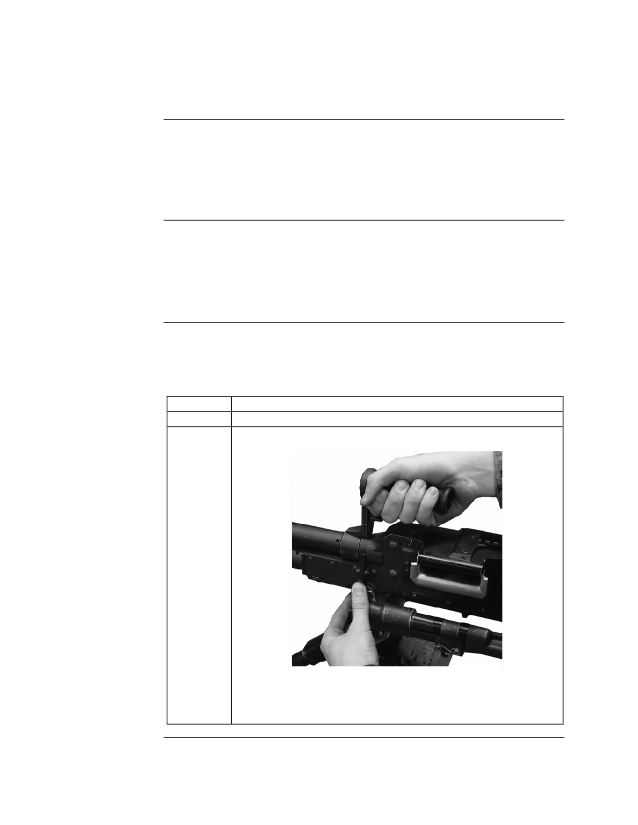
Changing the Barrel
Overview
The ability to change barrels on the M240G is a great advantage. It allows
one barrel to cool while the other is being used. This increases the life of
each barrel and ensures a continuous rate of accurate fire. Changing the
barrels only takes a few seconds and significantly improves the rate of fire
and accuracy.
Frequency of
Barrels should be changed when they begin to overheat. Barrel change is
Changes
required after
•
10 minutes of firing at a sustained rate
•
2 minutes of firing at a rapid rate
Barrel
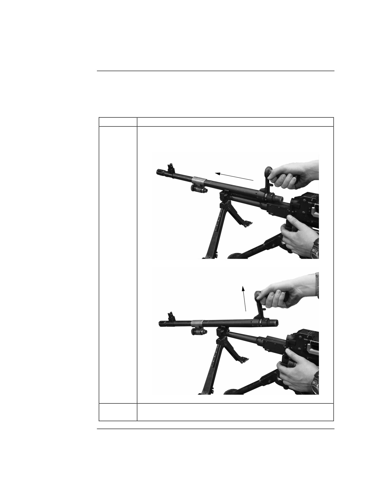
The barrel can be changed with the bolt to the front or to the rear. If the bolt
Changing
is to the rear, the weapon should be placed on SAFE. The procedure to
Procedure
change the barrel begins in the table below:
Step
Action
1
Depress and hold the barrel locking latch in.
2
Rotate the barrel carrying handle to the up position.
Note: Do not rotate the barrel carrying handle to the up
position using the carrying handle release latch. This
will not unlock the breach from the socket.
Continued on next page
MCI Course 0321B
3-37
Study Unit 3, Lesson 3
Changing the Barrel, Continued
Barrel
Changing
Procedure,
continued
Step
Action
3
Push forward and up on the barrel changing handle, separating
the barrel from the receiver.
4
Place the barrel on a clean surface or the spare barrel bag to
cool.
Continued on next page
MCI Course 0321B
3-38
Study Unit 3, Lesson 3
Changing the Barrel, Continued
Barrel
Changing
Procedure,
continued
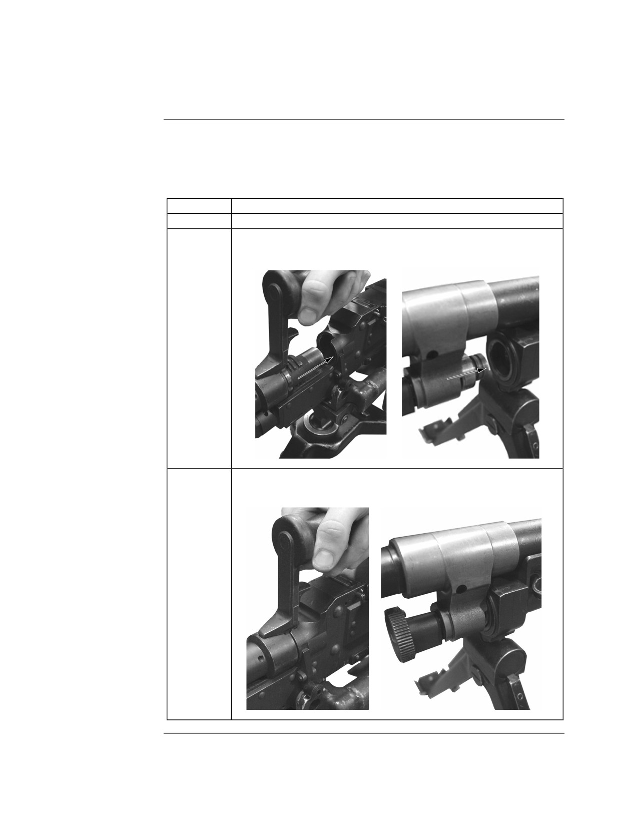
Step
Action
5
Grab the spare barrel by the barrel changing handle.
6
Insert the barrel socket into the receiver ensuring the gas plug is
aligned with the gas cylinder.
7
Pull the barrel to the rear until the barrel is fully seated in the
receiver.
Continued on next page
MCI Course 0321B
3-39
Study Unit 3, Lesson 3
Changing the Barrel, Continued
Barrel
Changing
Procedure,
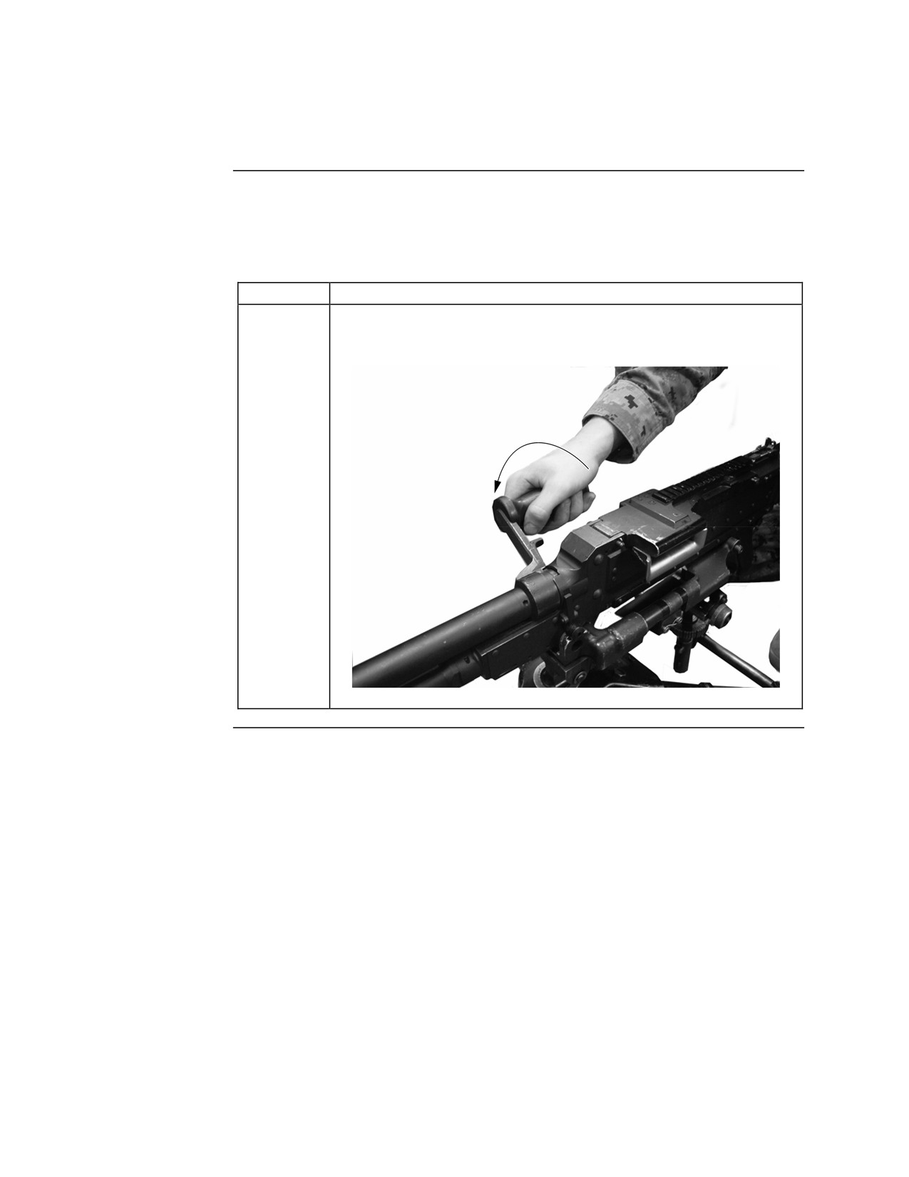
continued
Step
Action
8
Rotate the barrel changing handle to the down position,
counting clicks to verify proper headspace.
MCI Course 0321B
3-40
Study Unit 3, Lesson 3
Lesson 3 Exercise
Directions
Complete exercise items 1 through 10 by performing the action required.
Check your answers against those listed at the end of this lesson.
Item 1
Complete the statement below.
Fire a burst of ______ rounds with a pause of _____ seconds to achieve a
rapid rate of fire.
Item 2
Complete the statement below.
In the down (horizontal) position, the rear sight allows for ranges from
_______ meters.
Item 3
Explain how to adjust the rear sight assembly to the required range setting.
_____________________________________________________________
_____________________________________________________________
Item 4
Define sight alignment.
_____________________________________________________________
_____________________________________________________________
Item 5
Define sight picture.
_____________________________________________________________
_____________________________________________________________
Continued on next page
MCI Course 0321B
3-41
Study Unit 3, Lesson 3 Exercise
Lesson 3 Exercise, Continued
Item 6
When firing the M240G from the bipod, the gunner is in a prone position
behind the weapon with the buttstock in the ________ shoulder with the
_______ hand on the pistol grip.
a. right; right
b. left; right
c. right; left
d. left; left
Item 7
When firing the M240G from the tripod, the gunner is in a prone position
behind the weapon with the _______ hand on the pistol grip and the _______
hand on the _________ hand wheel.
a. right; left; traversing
b. left; right; traversing
c. right; left; elevation
d. left; right; elevation
Item 8
Rotate the traversing hand wheel to the __________ to move the impact of
the rounds to the left.
Item 9
Change the barrel after firing for _______ minutes at the sustained rate.
Continued on next page
MCI Course 0321B
3-42
Study Unit 3, Lesson 3 Exercise
Lesson 3 Exercise, Continued
Item 10
List in order the steps to change the barrel on the M240G.
1.
____________________________________________________________
____________________________________________________________
2.
____________________________________________________________
____________________________________________________________
3.
____________________________________________________________
____________________________________________________________
4.
____________________________________________________________
____________________________________________________________
5.
____________________________________________________________
____________________________________________________________
6.
____________________________________________________________
____________________________________________________________
7.
____________________________________________________________
____________________________________________________________
8.
____________________________________________________________
____________________________________________________________
Continued on next page
MCI Course 0321B
3-43
Study Unit 3, Lesson 3 Exercise
Lesson 3 Exercise, Continued
Answers
The table below lists the answers to the exercise items on the previous pages.
If you have any questions about the items, refer to the reference page.
Item Number
Answer
Reference Page
1
10-12; 2-3
3-29
2
200 to 800
3-30
3
Squeeze the catches on the side of the
3-30
rear sight and move it on the rear sight
slide to the desired range setting.
4
Sight alignment is the relationship
3-32
between the front sight blade, the rear
sight, and the aiming eye.
5
Sight picture is placing the tip of the
3-32
front sight blade on the target while
maintaining sight alignment.
6
a
3-33
7
c
3-34
8
rear toward you
3-35
9
10
3-37
Continued on next page
MCI Course 0321B
3-44
Study Unit 3, Lesson 3 Exercise
Lesson 3 Exercise, Continued
Answers,
continued
Item Number
Answer
Reference Page
10
1.
Depress and hold the barrel locking
3-37 through
latch in.
3-40
2.
Rotate the barrel changing handle to
the up position.
3.
Push forward and up on the barrel
changing handle, separating the
barrel from the receiver.
4.
Place the barrel on a clean surface
or the spare barrel bag to cool.
5.
Grab the spare barrel by the barrel
changing handle.
6.
Insert the barrel socket into the
receiver ensuring the gas plug is
aligned with the gas cylinder.
7.
Pull the barrel to the rear until the
barrel is full seated in the receiver.
8.
Rotate the barrel changing handle to
the down position, counting clicks
to verify proper headspace.
Lesson
In this lesson, you learned how to manipulate the trigger to achieve the
Summary
desired rate of fire, adjust the sights, aim, fire from the bipod and tripod, and
change the barrel.
In the next lesson, you will learn how to properly zero the weapon.
MCI Course 0321B
3-45
Study Unit 3, Lesson 3 Exercise
(This page intentionally left blank.)
MCI Course 0321B
3-46
Study Unit 3, Lesson 3 Exercise
LESSON 4
ZEROING
Introduction
Scope
The ability to provide accurate long-range machinegun fire is the key to
successful support with the M240G. To help ensure that initial burst is on
target, the barrels on the M240G must be properly zeroed. If the initial burst
is not on target, you must adjust the impact of the rounds onto the target.
Spending time adjusting your position with the bipod or adjusting the T&E on
the tripod allows the enemy to respond to your attack.
In this lesson, you will learn the procedures for zeroing the barrels.
Learning
Upon completion of this lesson, you should be able to
Objectives
• Identify the steps for adjusting the elevation on the front sight assembly.
• Identify the steps for adjusting the windage on the front sight assembly.
• Identify the steps for conducting a battlesight zero of the M240G medium
machinegun.
• Identify the steps for conducting a field expedient zero of the M240G
medium machinegun.
In This Lesson This lesson contains the following topics:
Topic
See Page
Introduction
3-47
Adjusting the Front Sight Assembly
3-48
Battlesight Zero
3-51
Field Expedient Zero
3-52
Lesson 4 Exercise
3-54
MCI Course 0321B
3-47
Study Unit 3, Lesson 4
Adjusting the Front Sight Assembly
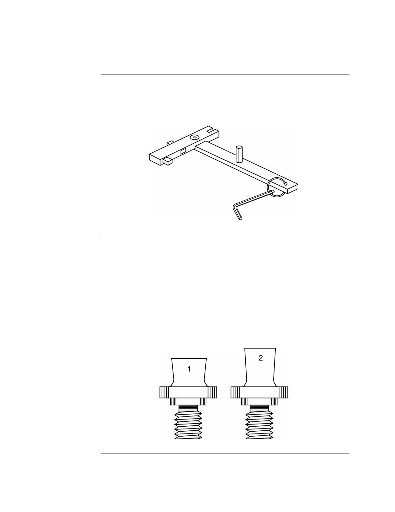
Adjusting Tool The front sight adjustment tool is part of the SL-3 components. It is used to
adjust the front sight of the M240G medium machinegun. It enables the
operator to unlock the front sight blade for adjusting elevation or turning the
socket head windage adjustment screws for adjusting windage.
Front Sight
There are two types of front sight blades. The number 1 blade is 9.8 mm and
Blade
the number 2 blade is 11.8 mm. If the required correction cannot be obtained
using the installed blade, the other blade should be used. The maximum
unscrewed position of either blade is where the base of the blade is flush with
the front sight protector surface. When zeroing, if the center of the shot group
is still above the point of aim with the number 1 blade unscrewed to the
maximum position, remove it and install the number 2 blade. If the center of
the shot group is still below the point of aim with the number 2 blade screwed
all the way in, remove it and install the number 1 blade. If the center of the
shot group cannot be brought to the point of aim after trying both blades, the
barrel assembly should be replaced.
Continued on next page
MCI Course 0321B
3-48
Study Unit 3, Lesson 4
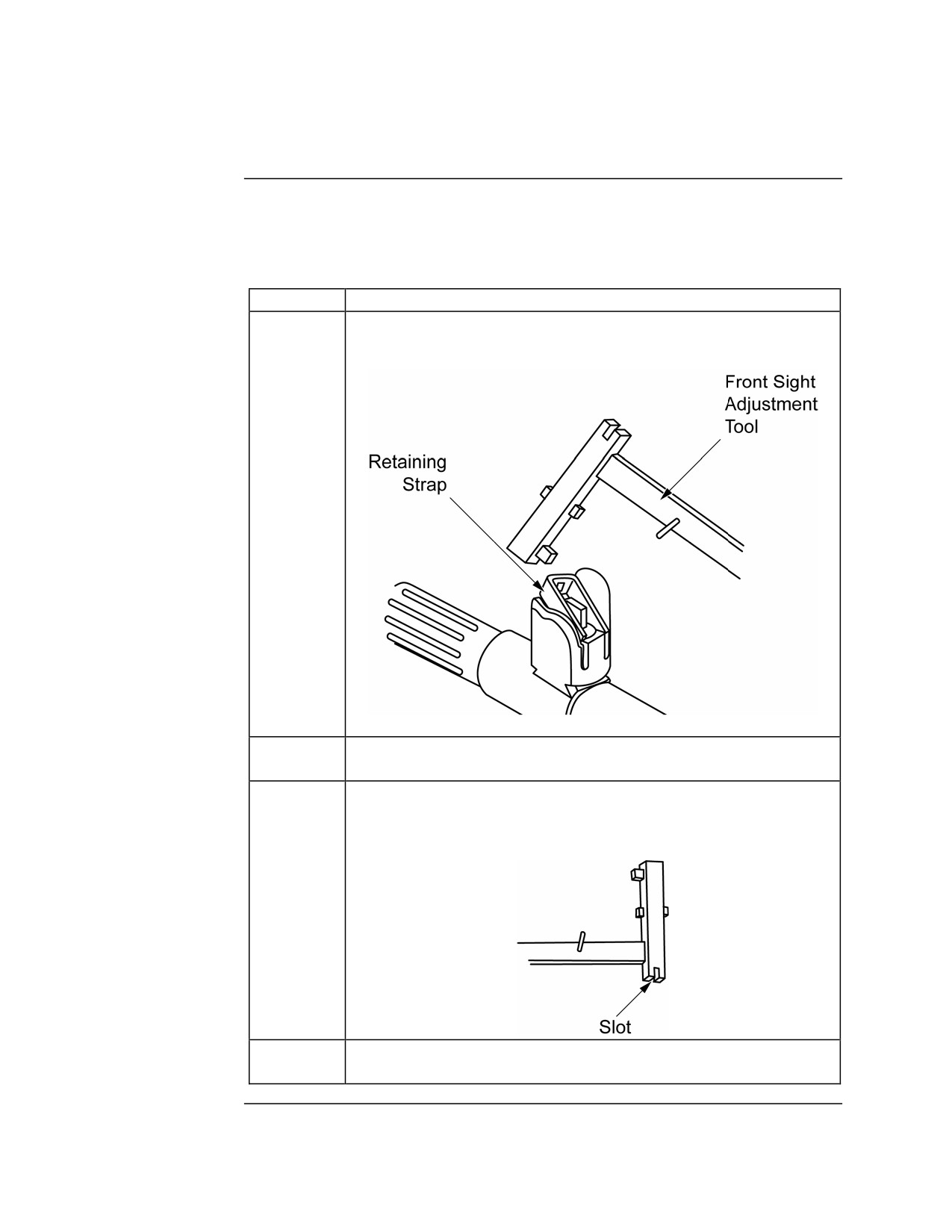
Adjusting the Front Sight Assembly, Continued
Adjusting for
Rotating the front sight blade clockwise raises the point of impact on the
Elevation
target. Rotating the front sight blade counter-clockwise lowers the point of
impact on the target. To adjust for elevation, use the following procedures.
Step
Action
1
Using the combination front sight adjusting tool, unlock the
retaining strap and rotate it upwards.
2
Apply a few drops of lubricant to the base of the front sight
blade to make it easier to turn.
3
Using the slotted end of the tool, place it over the front sight
blade. Rotate the front sight blade in the desired direction for
the required number of turns.
4
Lower the retaining strap but do not lock it until the zero is
complete.
Continued on next page
MCI Course 0321B
3-49
Study Unit 3, Lesson 4
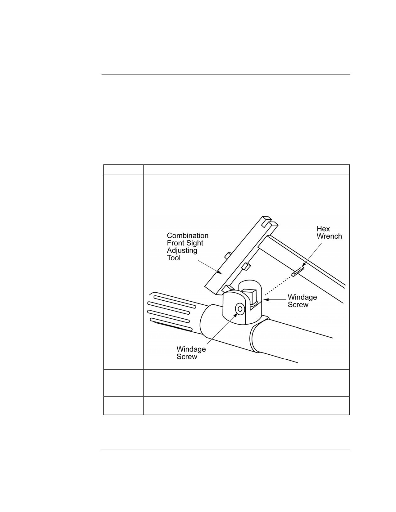
Adjusting the Front Sight Assembly, Continued
Adjusting for
Moving the front sight blade to the right moves the point of impact to the left.
Windage
Moving the front sight blade to the left moves the point of impact to the right.
The front sight windage adjustment procedure is the combination of creating
slack on one side, then taking up slack on the opposite side. The front sight
protector should always be tightly clamped between the two opposing
adjustment screws. As the adjusting crews are turned, noticeable clicks (eight
per full revolution) should be detected. If this is not the case, notify unit
maintenance. The procedure to adjust for windage is listed in the table below:
Step
Action
1
Using the hex wrench portion of the combination front sight
adjustment tool, loosen the adjusting screw on the side opposite
of the direction the front sight blade needs to move. To move
right, loosen left; to move left, loosen right.
2
Using the hex wrench, tighten the screw on the same side of the
direction the front sight blade needs to move. To move right,
tighten right; to move left, tighten left.
3
Once the windage is set, check that there is no play in the front
sight assembly. If there is, check both screws for looseness.
Note: The windage adjustment screws will break with the slightest over-
torquing. Be careful not to over tighten the adjustment screws.
MCI Course 0321B
3-50
Study Unit 3, Lesson 4
Battlesight Zero
Overview
Zeroing aligns the sights with the barrel so that point-of-aim equals point-of-
impact. Battlesight zero (BZO) is the sight settings used in combat and
enable engagement of targets within the M240G’s effective range in a no-
wind condition. The BZO is conducted with the M240G mounted on the
tripod at a range of 12.7 meters to the target. The target is a paper target with
a series of 1-inch black squares. Standard machinegun qualification targets
are normally used. When setting the BZO, all adjustments are made to the
front sight of the weapon. Each barrel of the M240G has to be individually
zeroed to ensure the accuracy of both barrels.
Procedure
The procedure for conducting a BZO is listed in the table below:
Step
Action
1
Leave the front sight post in its present position.
2
Set the rear sight elevation to 500 meters.
3
Load a belt of three rounds of ammunition.
4
Manipulate the T&E to get sight alignment and sight picture on
the 1-inch black square of the target.
5
Fire each round one at a time. Check the sight alignment and
sight picture between each shot.
6
Observe the impact of the group in relation to the target. Find
the approximate center of the group; this is the point of impact.
7
If the point of impact is not in the center of the target, adjust the
point of impact by manipulating the elevation and windage of
the front sight assembly based on the formula in the table below:
Adjustment
Formula
Elevation
1/2 turn equals 1/5 of an inch (5mm); 1 full
turn equals 3/8 of an inch (10mm).
Windage
1 full rotation (eight clicks) of the adjusting
screw equals 1/3 of an inch (8mm).
8
Repeat steps 3 through 7 to confirm the adjustments. If the
second shot group is not in the center of the target, continue
repeating until BZO is confirmed.
9
Repeat this procedure for the spare barrel.
MCI Course 0321B
3-51
Study Unit 3, Lesson 4
Field Expedient Zero
Overview
If the situation does not allow for the conduct of a BZO on a 12.7-meter firing
line, then a field expedient zero can be conducted. Any point of aim, point of
impact target can be used for a field expedient zero. A target that is between
300 and 700 meters is preferred. The target should be at the same elevation
as the firing position and have a solid mass behind it for observing the impact
of the rounds. For the field expedient zero, the M240G should be mounted on
the tripod.
Procedure
The procedure for conducting a field expedient zero is listed in the table
below:
Step
Action
1
Estimate the range to the target.
2
Place the range on the rear sight.
3
Center the T&E and adjust the position of the tripod to align the
gun to the target.
4
Adjust the T&E to get a correct sight alignment and sight
picture on the target.
5
Load a six-round belt of ammunition.
6
Fire a group of six rounds and observe the impact of the rounds
in relation to the target.
Continued on next page
MCI Course 0321B
3-52
Study Unit 3, Lesson 4
Field Expedient Zero, Continued
Procedure,
continued
Step
Action
7
If the center of the group does not impact the target, adjust the
elevation and windage of the front sight assembly.
•
To adjust the elevation, use the table below:
One full turn of the front sight blade
Range to Target
moves the impact of the round
100
4.25 inches
200
8.5 inches
300
12.75 inches
400
17.0 inches
500
21.25 inches
600
25.5 inches
700
29.75 inches
800
34.0 inches
900
38.25 inches
•
To adjust the windage, use the table below:
One full turn of the adjusting screws
Range to Target
moves the impact of the round
100
3.15 inches
200
6.3 inches
300
9.45 inches
400
12.6 inches
500
15.75 inches
600
18.9 inches
700
22 inches
800
25.2 inches
900
28.35 inches
8
Repeat steps 5 through 7 to confirm the zero.
9
Repeat for the spare barrel.
MCI Course 0321B
3-53
Study Unit 3, Lesson 4
Lesson 4 Exercise
Directions
Complete exercise items 1 through 4 by performing the action required.
Check your answers against those listed at the end of this lesson.
Item 1
List in order the steps for adjusting the elevation on the front sight assembly.
1.
___________________________________________________________
___________________________________________________________
2.
___________________________________________________________
___________________________________________________________
3.
___________________________________________________________
___________________________________________________________
4.
___________________________________________________________
___________________________________________________________
Item 2
List in order the steps for adjusting the windage on the front sight assembly.
1.
___________________________________________________________
___________________________________________________________
2.
___________________________________________________________
___________________________________________________________
3.
___________________________________________________________
___________________________________________________________
Continued on next page
MCI Course 0321B
3-54
Study Unit 3, Lesson 4 Exercise
Lesson 4 Exercise, Continued
Item 3
Complete the following statement for adjusting the front sight assembly when
performing a battlesight zero on the M240G.
A half turn of the front sight blade moves the impact of the rounds _____
inches at 12.7 meters.
Item 4
Complete the following statement for adjusting the front sight assembly when
performing a field expedient zero on the M240G.
A full turn of the front sight blade moves the impact of the rounds ______
inches for every 100 meters of distance to the target.
Continued on next page
MCI Course 0321B
3-55
Study Unit 3, Lesson 4 Exercise
Lesson 4 Exercise, Continued
Answers
The table below lists the answers to the exercise items on the previous pages.
If you have any questions about the items, refer to the reference page.
Item
Reference
Answer
Number
Page
1
1.
Using the combination front sight adjusting
3-49
tool, unlock the retaining strap and rotate it
upwards.
2.
Apply a few drops of lubricant to the base
of the front sight blade to make it easier to
turn.
3.
Using the slotted end of the tool, place it
over the front sight blade. Rotate the front
sight blade in the desired direction for the
required number of turns.
4.
Lower the retaining strap but do not lock it
until the zero is complete.
2
1.
Using the hex wrench portion of the
3-50
combination front sight adjustment tool,
loosen the adjusting screw on the side
opposite of the direction the front sight
blade needs to move. To move right,
loosen left; to move left; loosen right.
2.
Using the hex wrench, tighten the screw on
the same side of the direction the front sight
blade needs to move. To move right,
tighten right; to move left, tighten left.
3.
Once the windage is set, check that there is
no play in the front sight assembly. If there
is, check both screws for looseness.
3
1/5 (one fifth)
3-51
4
4.25
3-53
Lesson
In this lesson, you learned how to adjust the front sight assembly and zero the
Summary
M240G.
In the next lesson, you will learn how to troubleshoot the M240G if it fails to
operate properly.
MCI Course 0321B
3-56
Study Unit 3, Lesson 4 Exercise
LESSON 5
TROUBLESHOOTING
Introduction
Scope
In the middle of a firefight is not the time for your M240G to stop firing. If it
does, you must react quickly to identify and correct the problem and get the
weapon back into action. Your fellow Marines’ lives may depend on it.
In this lesson, you will learn how to identify a malfunction or a stoppage and
then apply immediate action or remedial action to remedy the problem.
Learning
Upon completion of this lesson, you should be able to
Objectives
• Define a malfunction.
• Identify sluggish operation.
• Identify the steps for adjusting the gas regulator setting.
• Identify a runaway gun.
• Identify the steps for correcting a runaway gun.
• Define a stoppage.
• Define a hangfire.
• Define a cook off.
• Define a hot barrel.
• Define immediate action.
• Identify the steps for applying immediate action.
• Define remedial action.
• Identify the steps for applying remedial action.
Continued on next page
MCI Course 0321B
3-57
Study Unit 3, Lesson 5
Introduction, Continued
In This Lesson This lesson contains the following topics:
Topic
See Page
Introduction
3-57
Malfunctions
3-59
Stoppages
3-61
Immediate Action
3-62
Remedial Action
3-64
Lesson 5 Exercise
3-71
MCI Course 0321B
3-58
Study Unit 3, Lesson 5
Malfunctions
Definition
A malfunction is a failure of the gun to function satisfactorily; the gun will
fire, but fire improperly. Defective ammunition or improper operation of the
gun by a crewmember is not considered a malfunction. Two of the more
common malfunctions are sluggish operation and a runaway gun.
Sluggish
Sluggish operation is when the M240G fires slower than its normal rate of
Operation
fire of 9 or 10 rounds per second. This can be due to excessive friction or a
loss of gas pressure. Excessive friction is due to a lack of lubrication or a
buildup of carbon or dirt in the gas system or on the bolt and receiver rails.
Loss of gas pressure is usually due to loose connections in the gas system.
The remedy for sluggish operation is for the operator to clean and lubricate
the weapon or have maintenance personnel tighten loose parts or replace worn
ones. If the current situation does not allow for this, sluggish operation can
be reduced by adjusting the gas regulator setting.
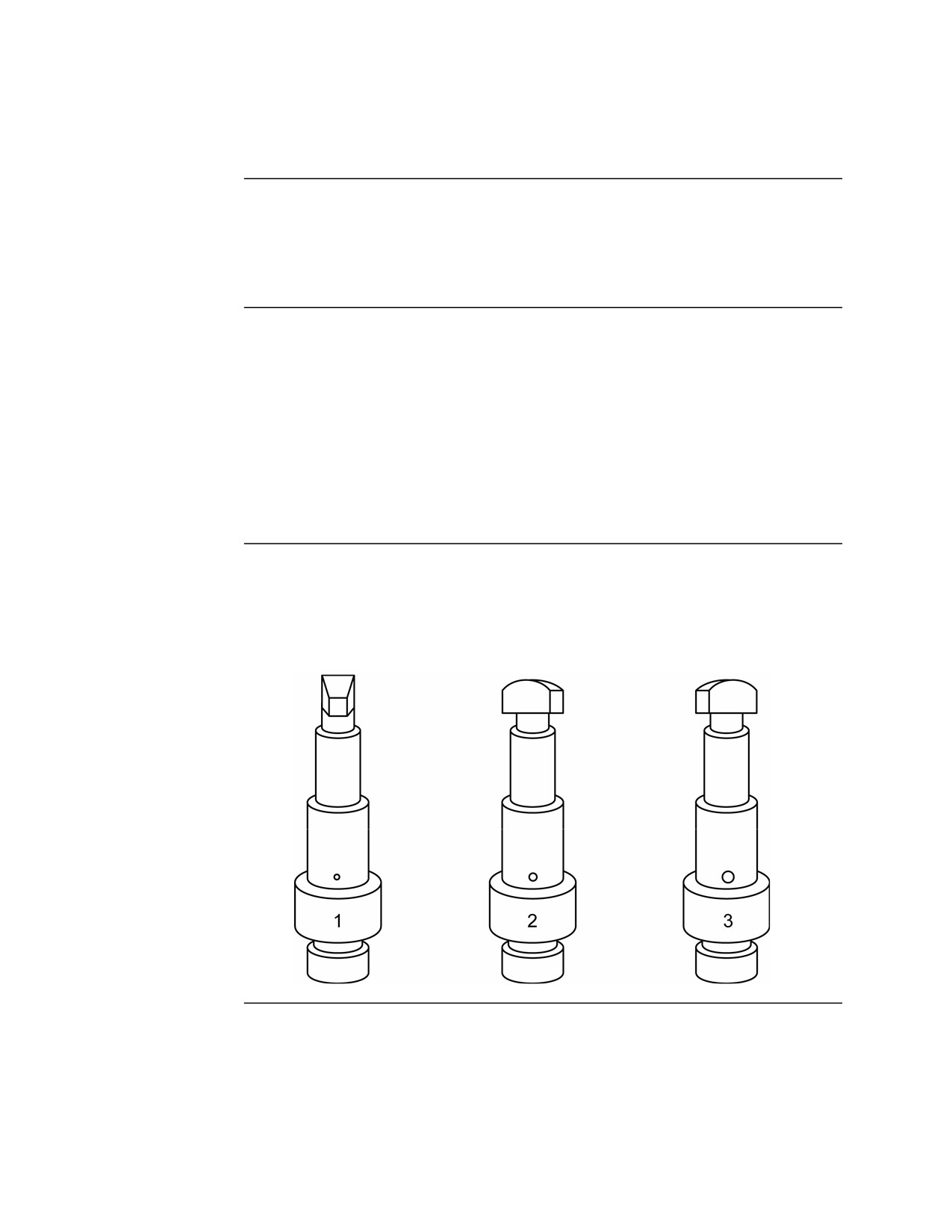
Gas Regulator The gas regulator plug has three different settings determined by three
Plug Settings
different size gas inlet holes. Each hole is numbered 1, 2, and 3. Hole 1 is
the smallest—the normal setting—and hole 3 is the largest. Always insert the
gas regulator plug with this setting after cleaning.
Continued on next page
MCI Course 0321B
3-59
Study Unit 3, Lesson 5
Malfunctions, Continued
Adjusting the
If the weapon becomes sluggish, the gas regulator plug can be removed,
Gas Regulator
rotated to setting 2 or 3, and reinserted. This adjustment should reduce the
Setting
sluggish operation until the operator can perform maintenance on the weapon.
The steps to adjust the gas regulator setting are listed in the table below:
Step
Action
1
Clear the weapon and make condition 4.
2
Remove the barrel.
3
Remove the gas collar and gas regulator plug.
4
Reinsert the gas regulator plug with setting 2 or 3.
5
Attach the gas collar.
6
Attach the barrel.
7
Continue with mission.
Runaway Gun
A runaway gun occurs when the weapon continues to fire after the trigger is
released. Firing is uncontrolled. A runaway gun is usually caused by a worn,
broken, or burred sear in the trigger housing group or a worn sear notch on
the operating rod. The sear shoulder is unable to grab the operating rod and
hold it to the rear after the trigger is released. The steps to stop a runaway
gun are listed in the table below:
Step
Action
1
Keep the weapon pointed towards the target.
2
If there are fewer than 50 rounds, let the rounds fire out.
3
If there are more than 50 rounds or the fire needs to cease
immediately, grasp the belt of ammunition with both hands and
twist the hands in opposite directions to break the belt of
ammunition.
4
Let the remaining rounds fire out.
5
Clear the weapon and make condition 4.
6
Turn weapon in to maintenance personnel for repairs before
using again.
Note: As a last resort, grasp the cocking handle and hold to the rear. This is
a last resort because of likely damage to the gun.
MCI Course 0321B
3-60
Study Unit 3, Lesson 5
Stoppages
Definition
A stoppage is any interruption in the cycle of functioning caused by faulty
action of the gun or defective ammunition that causes the weapon to stop
firing.
Hangfire
A hangfire occurs when there is a delay in the round firing after the firing pin
strikes the primer on the round.
Cook Off
A cook off occurs when a round discharges before being fully fed and locked
inside the chamber due to the high heat of the barrel.
Hot Barrel
A barrel is considered hot if more than 200 rounds have been fired in the last
2 minutes.
MCI Course 0321B
3-61
Study Unit 3, Lesson 5
Immediate Action
Definition
Immediate action is the prompt action taken by the operator to reduce a
stoppage without investigating the cause.
Procedure
When a stoppage occurs, you must react quickly to clear the stoppage and
return the weapon to operation in order to maintain a continuous rate of fire.
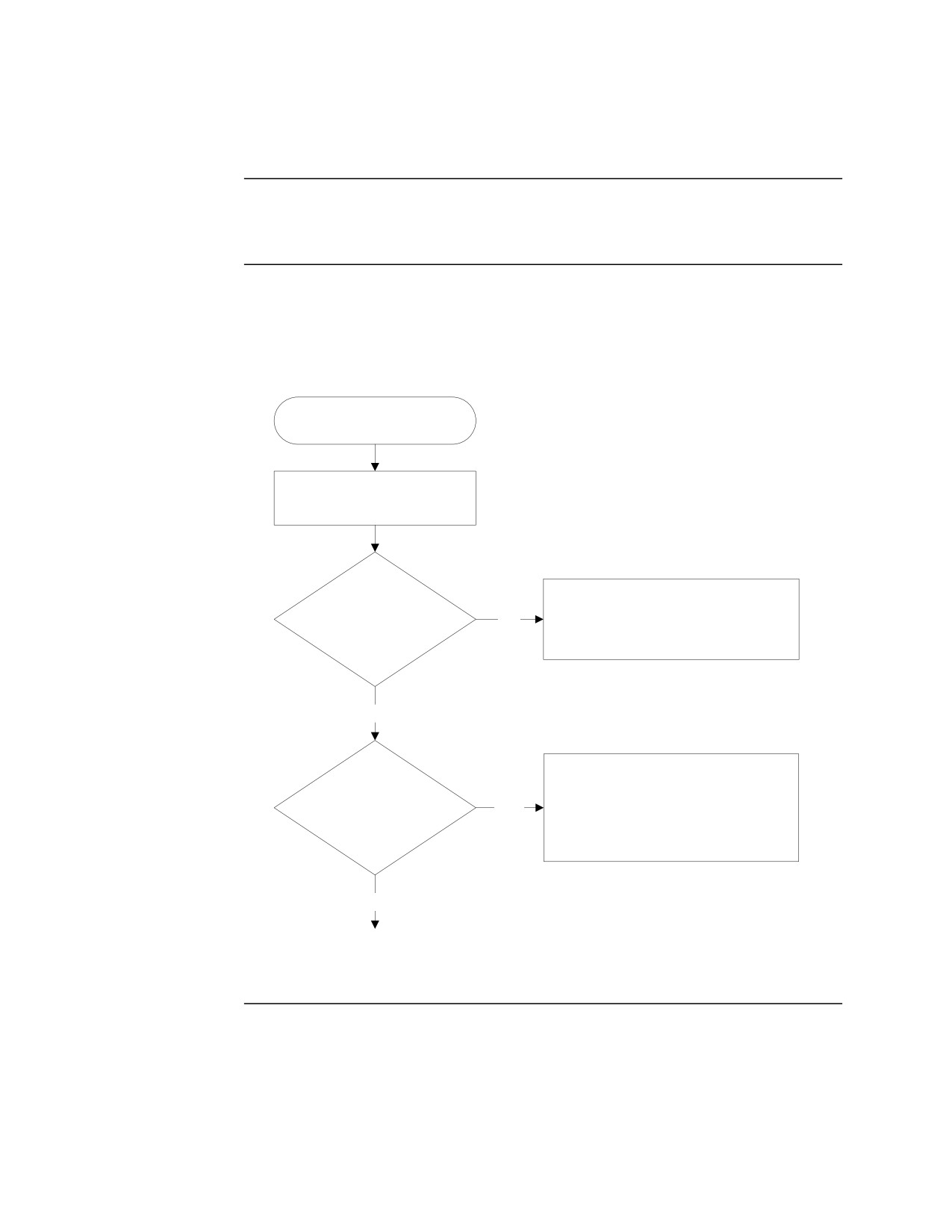
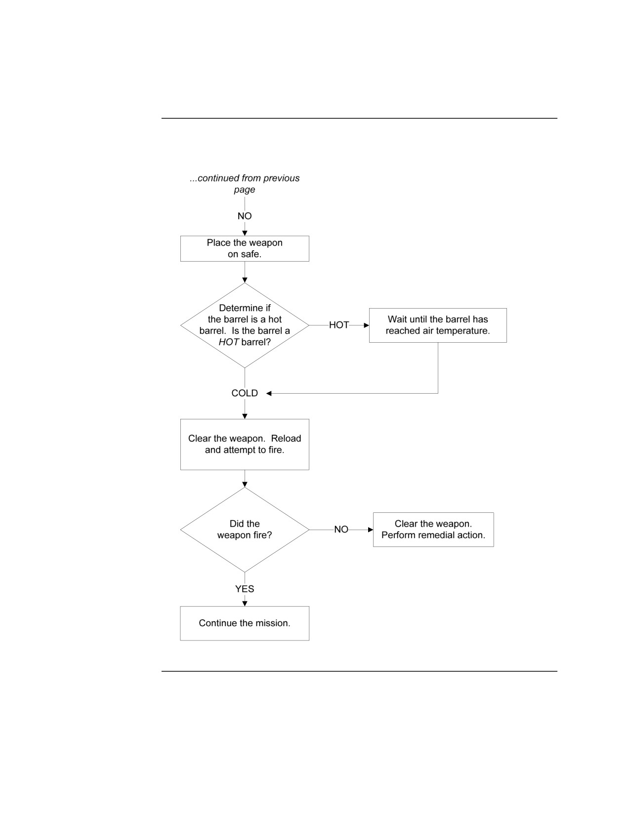
The procedure for conducting immediate action is illustrated in the chart
below:
Stoppage Occurs
Wait 5 seconds for possible
hangfire.
Attempt to
Let the barrel cool to air
lock the bolt to the rear.
NO
temperature. Unload and
Can the bolt be locked
perform remedial action.
to the rear?
YES
Observe for
Attempt to fire. If the weapon fails
ejecting brass. Was a
to fire again, wait 5 seconds, lock
YES
round or casing
the bolt to the rear, unload, and
ejected?
perform remedial action.
NO
Go to next page...
Continued on next page
MCI Course 0321B
3-62
Study Unit 3, Lesson 5
Immediate Action, Continued
Procedure,
continued
MCI Course 0321B
3-63
Study Unit 3, Lesson 5
Remedial Action
Definition
When immediate action fails to correct the stoppage, remedial action must be
taken. Remedial action is the action taken to inspect, identify, and correct the
cause of the stoppage. The cause can be due to either the weapon or the
ammunition. Performing remedial action may involve some disassembly of
the weapon to determine the cause.
Procedure
The procedure for remedial action is based on the problem. To determine the
problem, use the cycle of operation as a guide to narrow down the cause.
Determine at what stage in the cycle of operation the weapon had a stoppage
and use the guidelines below.
Failure to Fire
If the weapon failed to fire on the initial burst, do the following:
on Initial Burst
• Check the safety. If the safety is on SAFE, place it on FIRE.
• Check the ammunition. Raise the cover and ensure the belt of ammunition
is loaded properly.
• Check the weapon condition. Pull the charging handle to the rear to
ensure the weapon is properly charged.
• Check the ammunition. Pull the charging handle to the rear to eject a
defective round.
Continued on next page
MCI Course 0321B
3-64
Study Unit 3, Lesson 5
Remedial Action, Continued
Failure to Feed If the weapon failed to feed ammunition properly, do the following:
• Make sure the rounds in the belt of ammunition are aligned properly.
Reload if necessary.
• Make sure the belt of ammunition is not inverted in the feed tray. If so,
remove it and load the ammunition with the open side of the links facing
down.
• Check the ammunition for defective links or rounds. Remove any
defective ammunition.
• Check for obstructions in the receiver. Remove any obstructions.
• Check the receiver and operating groups for proper lubrication. Apply
lubrication if needed.
• Check the cover assembly for damaged, missing, or weak parts. If
problems exist, notify unit maintenance.
• Make sure the cover is properly closed and secure.
Stops Firing
If the weapon stopped firing, do the following:
• Check for a defective round in the chamber and eject the round.
• Check for an unfired round with a dented primer. Eject the round and
notify unit maintenance.
• Check that the bolt assembly is fully forward and locked. Remove any
obstructions or clean and lubricate the operating group and inside the
receiver.
• Check for a sticking feeding mechanism. Clean and lubricate the feed
mechanism. If problem continues, notify unit maintenance.
• Check for a short recoil. Clean and lubricate the operating group and
inside the receiver. If problem continues, notify unit maintenance.
Sluggish
If the rate of fire cannot be maintained with proper trigger manipulation,
Operation
check for a dirty receiver. Clean and lubricate the receiver as necessary.
Continued on next page
MCI Course 0321B
3-65
Study Unit 3, Lesson 5
Remedial Action, Continued
Failure to
If the weapon failed to chamber a round, do the following:
Chamber
• Check for a stuck or ruptured cartridge case. Remove the stuck or
ruptured cartridge case.
• Check for dirty ammunition. Wipe the ammunition off with a clean rag.
• Check for built-up carbon in the receiver to include the gas cylinder.
Clean if necessary.
• Check for a damaged round. Remove the round and recharge the weapon.
• Check for a damaged or weak drive spring. Notify unit maintenance if
necessary.
• Check for a damaged gas regulator plug. Notify unit maintenance if
necessary.
• Check for a dirty chamber. Clean as necessary.
Failure to Fire
If the weapon failed to fire, do the following:
• Check for faulty ammunition. Unload and replace if necessary.
• Check for a damaged firing pin. Notify unit maintenance if necessary.
• Check for a damaged or weak drive spring. Notify unit maintenance if
necessary.
Failure to
If the bolt failed to extract a cartridge, do the following:
Extract
• Check for a short recoil. Clean and lubricate the operating group and
inside the receiver. If problem continues, notify unit maintenance.
• Check for a damaged extractor or extractor spring on the bolt. Notify unit
maintenance if necessary.
Continued on next page
MCI Course 0321B
3-66
Study Unit 3, Lesson 5
Remedial Action, Continued
Failure to Eject If the bolt failed to eject a cartridge, do the following:
• Check for a short recoil. Clean and lubricate the operating group and
inside the receiver. If problem continues, notify unit maintenance.
• Check for a damaged ejector or ejector spring on the bolt. Notify unit
maintenance if necessary.
• Check under the weapon to see if spent cartridges are piled high enough to
block ejection port. Clear away spent cartridges if needed.
Failure to Cock If the bolt failed to lock to the rear or cock the weapon, do the following:
• Check for a damaged or worn sear. Notify unit maintenance if necessary.
• Check for a stuck sear. Notify unit maintenance if necessary.
• Check for a damage or worn sear notch on the operating rod. Notify unit
maintenance if necessary.
• Check for a short recoil. Clean and lubricate the operating group and
inside the receiver. If problem continues, notify unit maintenance.
Continued on next page
MCI Course 0321B
3-67
Study Unit 3, Lesson 5
Remedial Action, Continued
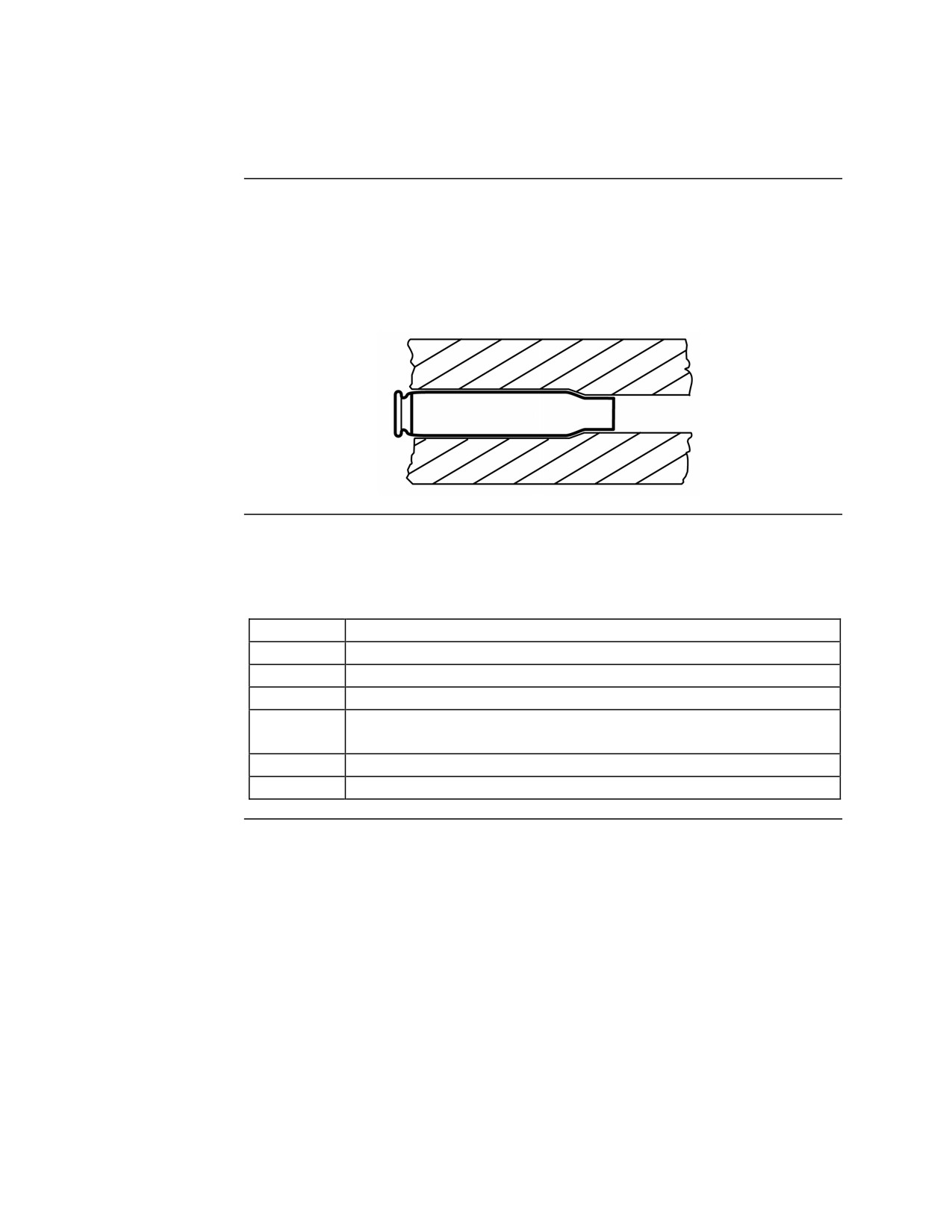
Stuck
Over time, the extractor spring may weaken from use causing the extractor
Cartridge
not to tightly grip the base of the cartridge. When the bolt moves to the rear,
the cartridge is released and not removed from the chamber. Other times,
when a round is fired, some swelling of the cartridge occurs. When this
swelling is excessive, the cartridge can become fixed inside the chamber.
Removing a
The steps for removing a stuck cartridge are listed in the table below:
Stuck
Cartridge
Step
Action
1
Lock the bolt to the rear.
2
Place the weapon on safe.
3
Assemble the cleaning rod.
4
Insert the cleaning rod into the muzzle end of the barrel to push
the stuck cartridge out of the chamber.
5
Remove the cleaning rod.
6
Continue the mission.
Continued on next page
MCI Course 0321B
3-68
Study Unit 3, Lesson 5
Remedial Action, Continued
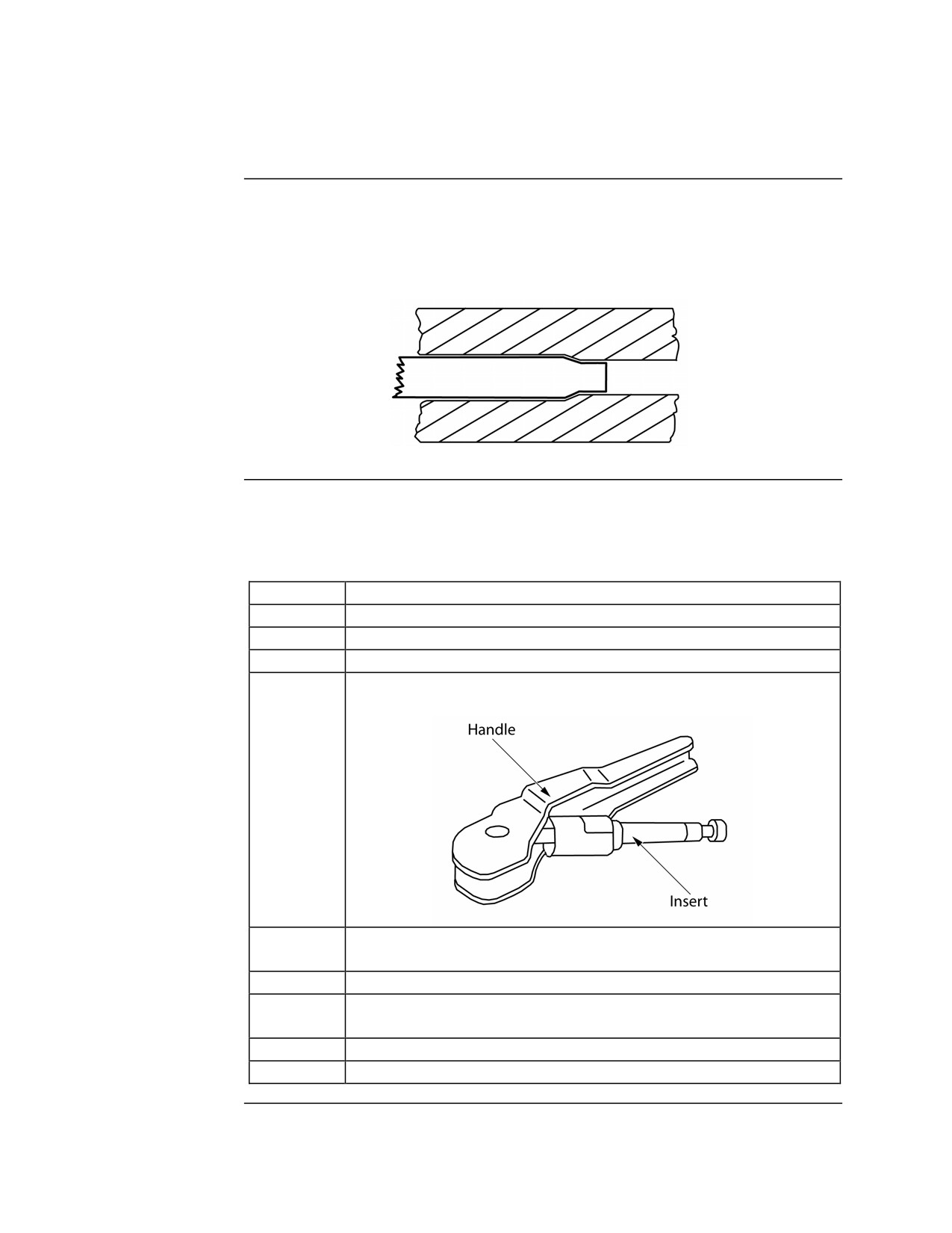
Ruptured
When a round is fired, it can cause the cartridge to weaken. Again, swelling
Cartridge
may occur. When both of these happen, the extractor may rip the base of the
cartridge off during the extraction process leaving behind the upper portion of
the cartridge in the chamber.
Removing a
The ruptured cartridge extractor tool is used to help the operator remove a
Ruptured
rupture cartridge. The steps for removing a ruptured cartridge are listed in the
Cartridge
table below:
Step
Action
1
Lock the bolt to the rear.
2
Place the weapon on safe.
3
Remove the barrel.
4
Insert the ruptured cartridge case extractor into the ruptured
cartridge.
5
Rotate the handle away from the barrel making the extractor
grasp the ruptured cartridge.
6
Holding the handle, pull the ruptured cartridge from the barrel.
7
Visually inspect the chamber for damage or debris. Clean if
necessary.
8
Reattach the barrel.
9
Continue the mission.
Continued on next page
MCI Course 0321B
3-69
Study Unit 3, Lesson 5
Remedial Action, Continued
Stuck and
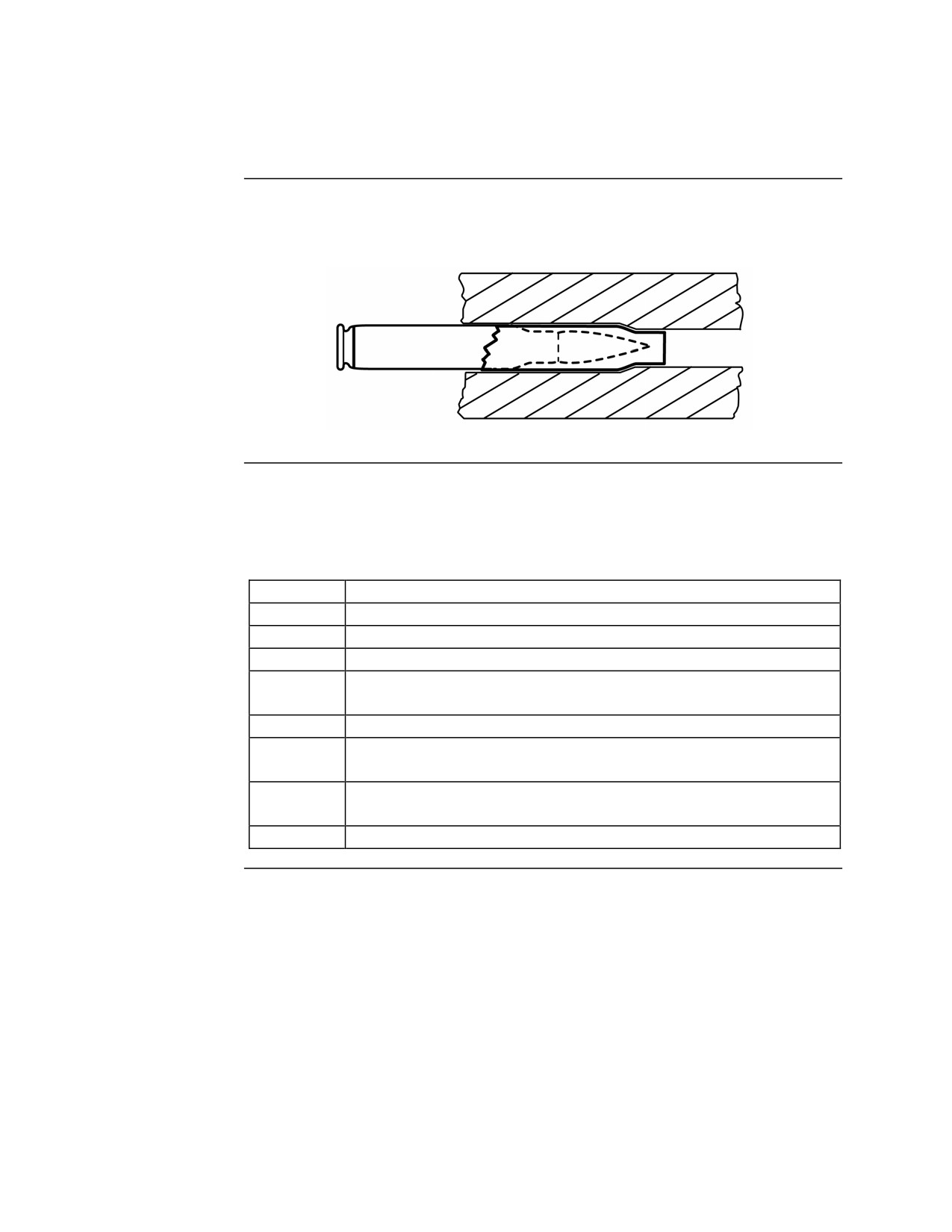
When a ruptured cartridge occurs, there is a possibility that another round has
Ruptured
been chambered into the ruptured cartridge.
Cartridge
Removing
The steps for removing a stuck cartridge and a ruptured cartridge are listed in
Stuck and
the table below.
Ruptured
Cartridge
Step
Action
1
Lock the bolt to the rear.
2
Place the weapon on safe.
3
Remove the barrel.
4
Insert the cleaning rod into the muzzle end of the barrel to push
the cartridges out of the chamber.
5
Remove the cleaning rod.
6
If both cartridges have been removed, reattach the barrel and
continue the mission.
7
If the rupture cartridge remains, follow the procedure for
removing a ruptured cartridge.
8
Continue the mission.
MCI Course 0321B
3-70
Study Unit 3, Lesson 5
Lesson 5 Exercise
Directions
Complete exercise items 1 through 15 by performing the action required.
Check your answers against those listed at the end of this lesson.
Item 1
Define malfunction.
______________________________________________________________
______________________________________________________________
Item 2
What is sluggish operation?
______________________________________________________________
______________________________________________________________
Item 3
List the steps for adjusting the gas regulator setting.
•
____________________________________________________________
•
____________________________________________________________
•
____________________________________________________________
•
____________________________________________________________
•
____________________________________________________________
•
____________________________________________________________
•
____________________________________________________________
Item 4
What is a runaway gun?
______________________________________________________________
______________________________________________________________
Continued on next page
MCI Course 0321B
3-71
Study Unit 3, Lesson 5 Exercise
Lesson 5 Exercise, Continued
Item 5
List the steps for correcting a runaway gun.
•
____________________________________________________________
•
____________________________________________________________
•
____________________________________________________________
•
____________________________________________________________
•
____________________________________________________________
•
____________________________________________________________
Item 6
Define stoppage.
______________________________________________________________
______________________________________________________________
Item 7
Define hangfire.
______________________________________________________________
______________________________________________________________
Item 8
Define cook off.
______________________________________________________________
______________________________________________________________
Item 9
A barrel is considered hot if more than __________ rounds have been fired in
the last ______ minutes.
Continued on next page
MCI Course 0321B
3-72
Study Unit 3, Lesson 5 Exercise
Lesson 5 Exercise, Continued
Item 10
Complete the statement below.
Immediate action is the ___________________________________________
______________________________________________________________
Item 11
When applying immediate action to a weapon that has stopped firing, the first
thing the operator should do is
a. pull the charging handle to the rear.
b. remove the barrel.
c. wait 5 seconds in case there is a hangfire.
d. open the cover to investigate.
Items 12
Matching: For items 12 through 15, match the problem in column 1 with the
Through 15
likely cause in column 2.
Column 1
Column 2
Problem
Cause
___ 12. Stuck cartridge
a. Cover not completely closed
___ 13. Ruptured cartridge
b. Weak extractor spring
___ 14. Failure to feed
c. Damaged firing pin
___ 15. Failure to fire
d. Base ripped from cartridge
Continued on next page
MCI Course 0321B
3-73
Study Unit 3, Lesson 5 Exercise
Lesson 5 Exercise, Continued
Answers
The table below lists the answers to the exercise items on the previous pages.
If you have any questions about the items, refer to the reference page.
Item Number
Answer
Reference Page
1
A failure of the gun to function
3-59
satisfactorily; the gun will fire, but fire
improperly.
2
The M240G fires more slowly than its
3-59
normal rate of fire of 9 or 10 rounds per
second.
3
• Clear the weapon and make
3-60
condition 4.
• Remove the barrel.
• Remove the gas collar and gas
regulator plug.
• Reinsert the gas regulator plug with
setting 2 or 3.
• Attach the gas collar.
• Attach the barrel.
• Continue with mission.
4
The weapon continues to fire after the
3-60
trigger is released.
5
• Keep the weapon point towards the
3-60
target.
• If there are fewer than 50 rounds, let
the rounds fire out.
• If there are more than 50 rounds or
the fire needs to cease immediately,
grasp the belt of ammunition with
both hands and twist the hands in
opposite directions to break the belt
of ammunition.
• Let the remaining rounds fire out.
• Clear the weapon and make
condition 4.
• Turn weapon in to maintenance
personnel for repairs before using
again.
Continued on next page
MCI Course 0321B
3-74
Study Unit 3, Lesson 5 Exercise
Lesson 5 Exercise, Continued
Answers,
continued
Item Number
Answer
Reference Page
6
Any interruption in the cycle of
3-61
functioning caused by faulty action of
the gun or defective ammunition that
causes the weapon to stop firing.
7
When there is a delay in the round
3-61
firing after the firing pin strikes the
primer on the round.
8
When a round discharges before being
3-61
fully fed and locked inside the chamber
due to the high heat of the barrel.
9
200; 2
3-61
10
Immediate action is the prompt action
3-62
taken by the operator to reduce a
stoppage without investigating the
cause.
11
c
3-62
12
b
3-68
13
d
3-69
14
a
3-65
15
c
3-66
Lesson
In this lesson, you learned how to identify and respond to the various
Summary
malfunction and stoppages that may occur when operating the M240G.
Study Unit
In this study unit, you have learned how mount, load and unload, fire, zero,
Summary
and troubleshoot the M240G medium machinegun. You now have the
requisite knowledge to operate this weapon and use it in training and more
importantly, combat.
In the next study unit, you will learn how to engage targets in periods of
limited visibility and darkness using special optics.
MCI Course 0321B
3-75
Study Unit 3, Lesson 5 Exercise
(This page intentionally left blank.)
MCI Course 0321B
3-76
Study Unit 3, Lesson 5 Exercise
STUDY UNIT 4
OPTICS
Overview
Scope
Your effectiveness as a machinegunner is based on your ability to engage
targets in periods of limited visibility and darkness. This can only be
accomplished through the use of optic systems designed for this purpose.
In this study unit, you will learn how to use special optics to engage targets
during periods of limited visibility and darkness.
In This Study
This study unit contains the following lessons:
Unit
Lesson
See Page
AN/PAS-13B V(2) Medium Weapon Thermal Sight
4-3
AN/PVS-17C Miniature Night Sight
4-17
MCI Course 0321B
4-1
Study Unit 4
(This page intentionally left blank.)
MCI Course 0321B
4-2
Study Unit 4
LESSON 1
AN/PAS-13B V(2) MEDIUM WEAPON THERMAL SIGHT
Introduction
Scope
This lesson will acquaint you with the AN/PAS-13B medium weapon thermal
sight (MWTS)—its characteristics and reticle indicators. Basic operation and
the mounting and zeroing procedures will also be discussed.
Learning
After completing this lesson, you should be able to
Objectives
• Identify the fields of view on the AN/PAS-13B.
• Identify the four major components of the AN/PAS-13B.
• Identify the controls for the AN/PAS-13B.
• Identify the indicators for the AN/PAS-13B.
• Identify the parts of the M240 reticle.
• Identify the steps for mounting the AN/PAS-13B to the M240G.
• Identify the steps for installing the battery into the AN/PAS-13B.
• Identify the steps for operating the AN/PAS-13B.
In This Lesson This lesson contains the following topics:
Topic
Page
Introduction
4-3
General Information
4-4
Controls
4-5
Reticle
4-8
Mounting
4-11
Operation
4-12
Lesson 1 Exercise
4-14
MCI Course 0321B
4-3
Study Unit 4, Lesson 1
General Information
Description
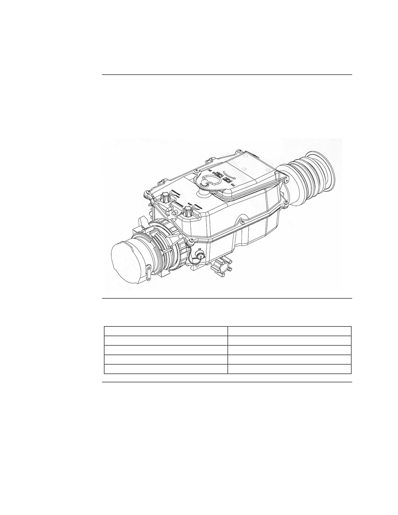
The AN/PAS-13B V(2) MWTS is a silent, lightweight, compact, durable,
battery-powered thermal sight that operates with low power consumption.
The MWTS is capable of target acquisition under conditions of limited
visibility—such as darkness, smoke, fog, dust, and haze—and operates just as
effectively during daylight.
Characteristics The characteristics of the MWTS are listed in he table below:
Characteristic
Dimension/Description
Height
6.25 inches
Width
6.25 inches
Length
15.50 inches
Weight
4.19 pounds
Continued on next page
MCI Course 0321B
4-4
Study Unit 4, Lesson 1
General Information, Continued
Field of View
The MWTS consists of two fields of view (FOV)—narrow and wide:
FOV
Description
Magnification
Narrow
6º
5.0 ×
Wide
18º
1.66 ×
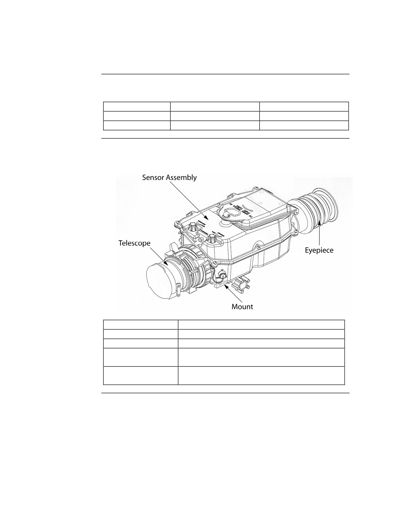
Four Major
The table below lists the MWTS components and their function:
Components
Component
Function
Telescope
Provides magnification of the thermal image
Sensor Assembly
Processes the thermal image for display
Eyepiece
Displays the thermal image and all system
indicators for the operator
Mount
Universal attachment that interface between the
MWTS and the weapon
MCI Course 0321B
4-5
Study Unit 4, Lesson 1
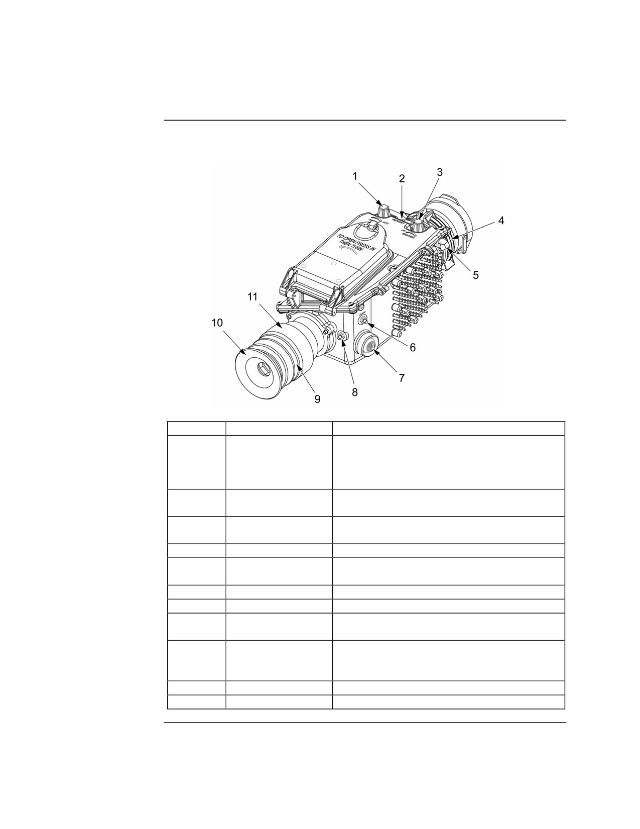
Controls and Indicators
Controls
The table below lists the MWTS controls and their function:
Item
Control
Function
1
Contrast Knob
Adjusts the contrast of the thermal scene.
When turned fully clockwise to the AUTO
detent position, contrast is automatically
controlled by the sight.
2
Emergency Select
Places the sight in emergency mode with the
system power on.
3
Brightness Knob
Turns system power ON and OFF. Adjusts
brightness of display.
4
Focus Knob
Adjusts focus of thermal scene.
5
FOV Knob
Selects either WIDE or NARROW field of
view.
6
Zoom/Reticle Select
Turns on the 2× zoom and changes the reticle.
7
Reticle Adjust
Used only for zeroing and sight aligning.
8
Black/White Select
Controls polarity (white hot or black hot) of
thermal scene.
9
Diopter Holding
For use with cathode ray tube display only. Not
Device
required on liquid crystal display. Allows
diopter to be adjusted.
10
Eyecup
Controls Standby or ON operating mode.
11
Diopter
Adjust focus of reticle and indicators.
Continued on next page
MCI Course 0321B
4-6
Study Unit 4, Lesson 1
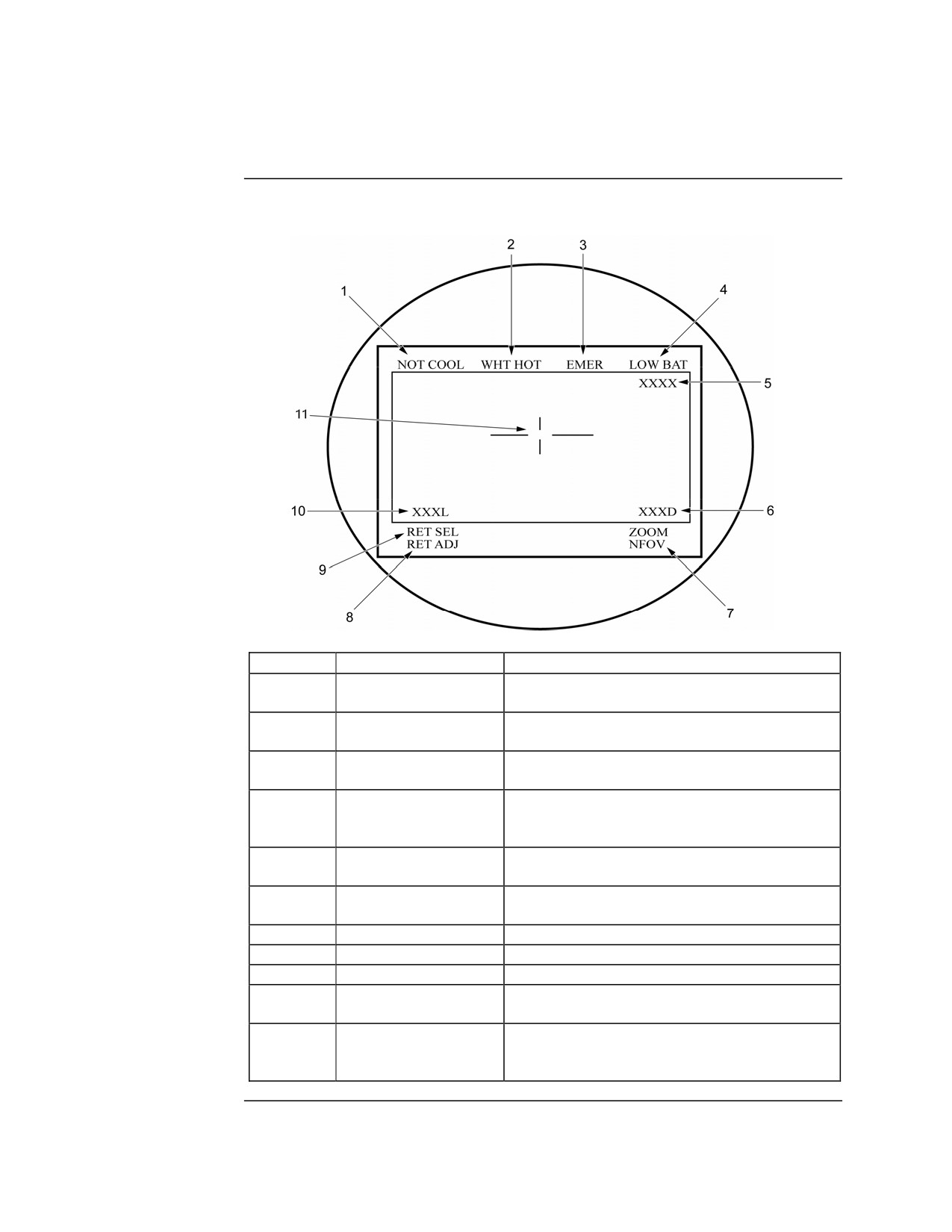
Controls and Indicators, Continued
Indicators
The table below lists the MWTS indicators and their function:
Item
Indicator
Function
1
NOT COOL
Displays when the system is not cool enough for
proper operation
2
WHT HOT/BLK HOT
Indicates the target polarity selected by the
BLK/WHT switch
3
EMER
Displays when the system is placed in
emergency mode
4
LOW BAT
Displays when battery power is low.
Approximately 15 minutes of battery time
remain
5
Reticle select/FOV
Identifies which reticle and FOV is currently
selected
6
Elevation
Indicates the elevation zeroing adjustment of the
reticle
7
NFOV/WFOV
Indicates wide FOV or narrow FOV
8
RET ADJ
Indicates the reticle adjustment mode is selected
9
RET SEL
Indicates the reticle select mode is selected
10
Azimuth
Indicates the azimuth zeroing adjustment of the
reticle
11
SENSOR COOLING
Displays when system is first turned on and
switches to the current reticle after
approximately 2 minutes
Continued on next page
MCI Course 0321B
4-7
Study Unit 4, Lesson 1
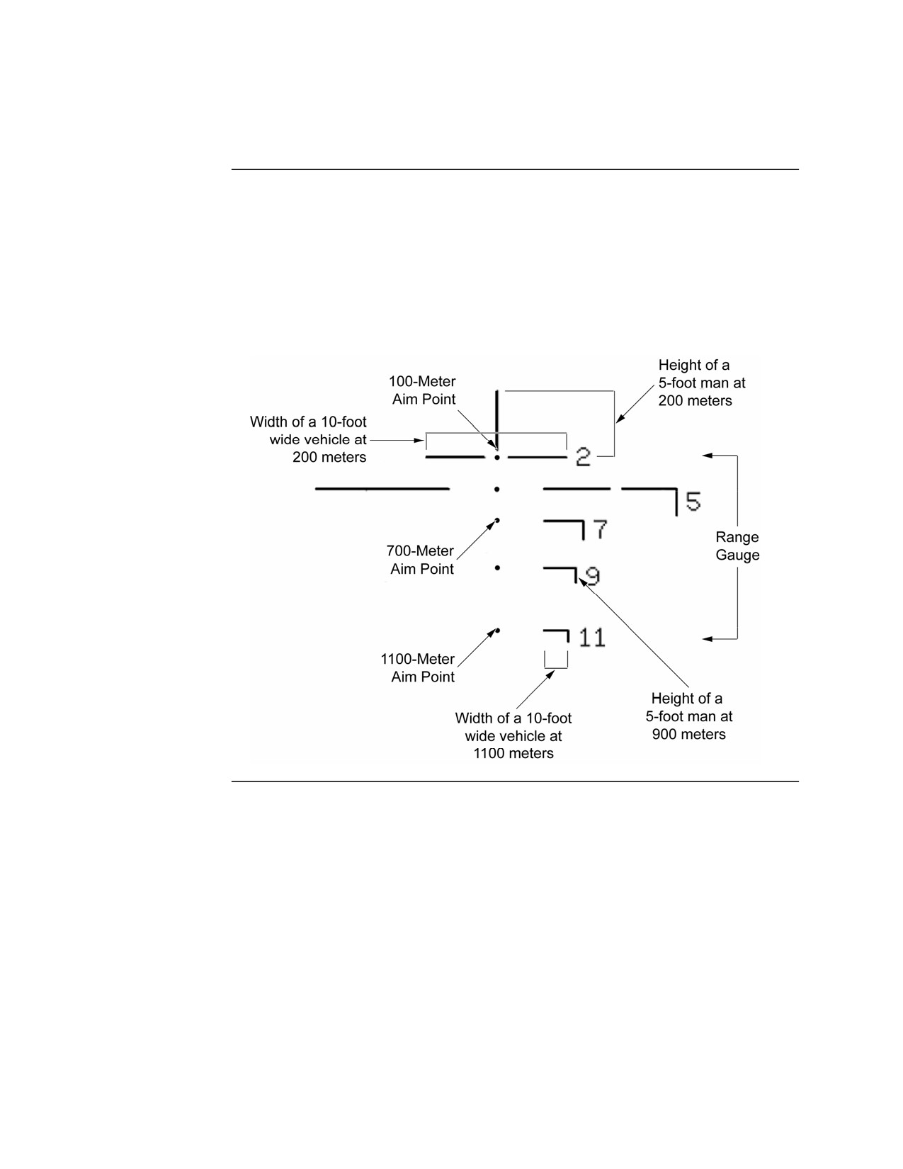
Reticles
General
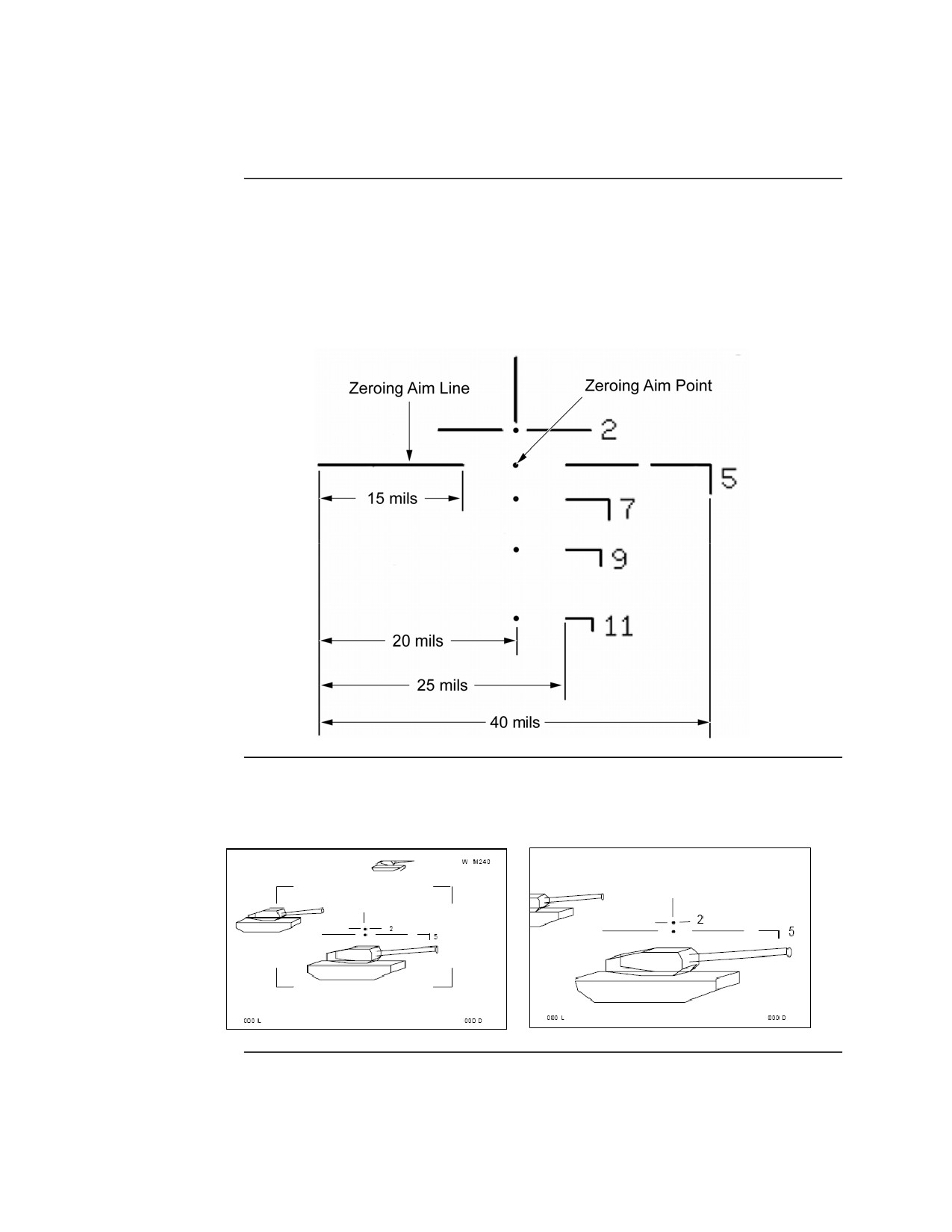
The M240 reticles provide multiple dot aim points and range gauges used for
range estimation and target firing. Each dot aim point is used for a different
range as indicated on the side of the range gauge. The bottom of the vertical
line above the 200-meter aim point is the 100-meter aim point. The height of
the vertical line at each aim point represents the height of a 5-foot tall man at
that range. The width of the horizontal line at each aim point represents the
width of a 10-foot-wide vehicle at that range.
Continued on next page
MCI Course 0321B
4-8
Study Unit 4, Lesson 1
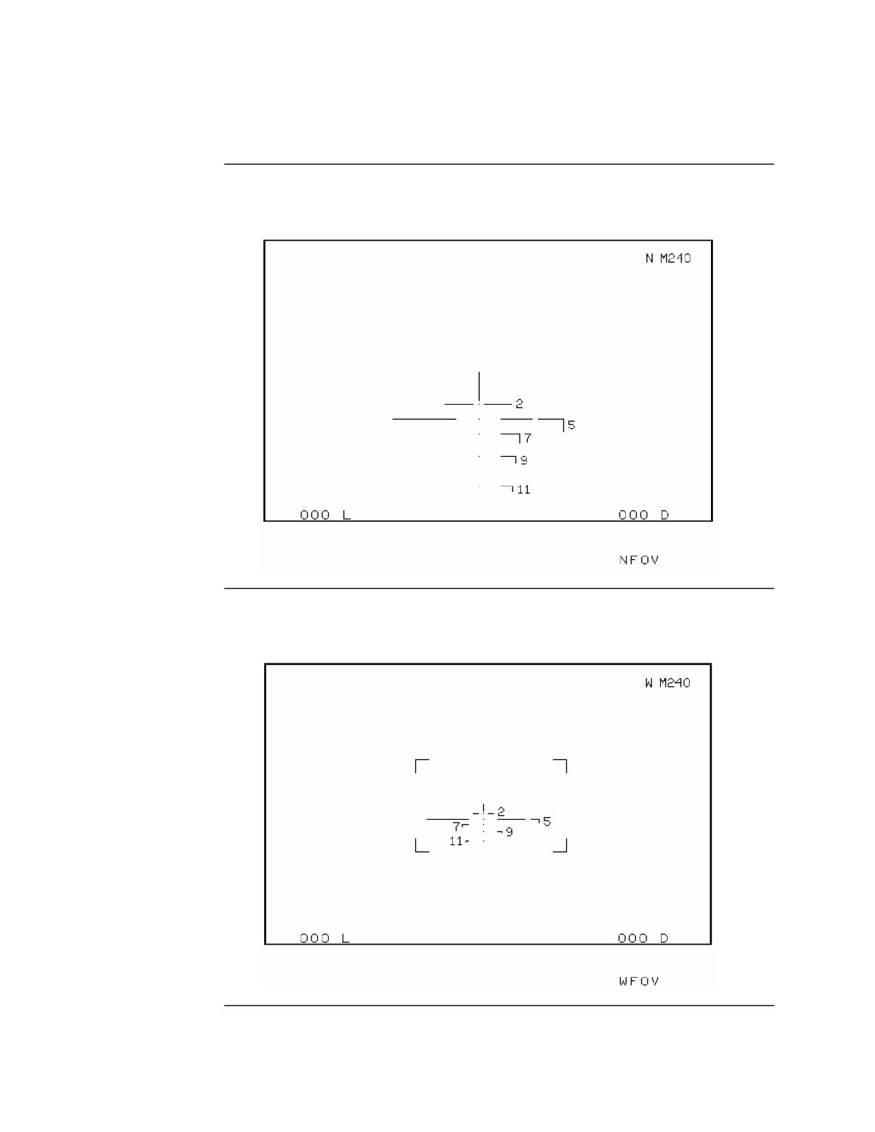
Reticles, Continued
M240 Narrow The M240 narrow field of view (NFOV) reticle is shown below:
FOV Reticle
M240 Wide
The M240 wide field of view (WFOV) reticle is shown below:
FOV Reticle
Continued on next page
MCI Course 0321B
4-9
Study Unit 4, Lesson 1
Reticles, Continued
Zeroing Aim
The zeroing aim line is composed of the horizontal lines to the left and right
Line and
of the zeroing aim point. The zeroing aim line serves two purposes:
Zeroing Aim
Point
• Indicates the zeroing aim point for reticles with multiple aim points
• Provides a means of measuring angles for combat preparation, directing
fire, and range estimation
Zoom
The MWTS has a 2-times electric zoom. When the zoom is activated, the
image size is doubled and the FOV is cut in half as shown below:
MCI Course 0321B
4-10
Study Unit 4, Lesson 1
Mounting
Introduction
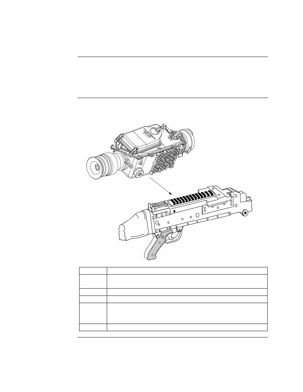
Make sure the M240G is in weapon condition 4 before mounting the
AN/PAS-13B. Avoid carrying the AN/PAS-13B by the eyecup, objective
lens cover, or battery cover. These items may detach from the site, causing it
to drop.
Procedure
The procedure for mounting the AN/PAS-13B to the M240G is listed in the
table below:
Step
Action
1
Make sure the rear sight of the M240G is in the down
(horizontal) position.
2
Loosen the mounting knob on the site.
3
Place the site on the mounting rail on the cover of the M240G.
4
Align the mounting rail of the AN/PAS-13 to the fourth slot
from the rear of the mounting rail on the M240G. Mounting the
site on a different slot can result in damage to the sight.
5
Hand tighten the mounting knob until two clicks are heard.
MCI Course 0321B
4-11
Study Unit 4, Lesson 1
Operation
Installing the
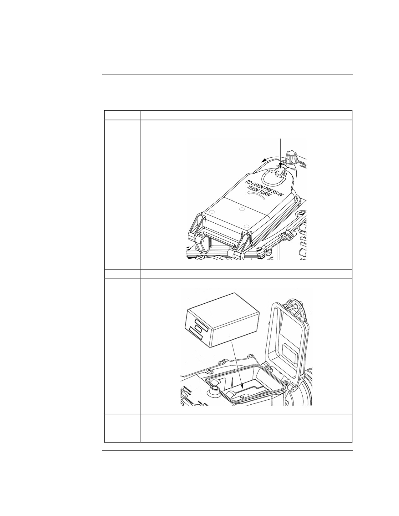
The procedure for installing the battery is listed in the table below:
Battery
Step
Action
1
Press in battery door latch, turn counterclockwise, and open
battery door.
2
Hold battery with contacts facing forward.
3
Install battery into battery compartment.
4
Close battery door. Press in while turning battery door latch
clockwise until battery door latch catches in slot. Continue
turning battery door latch one-quarter turn.
Continued on next page
MCI Course 0321B
4-12
Study Unit 4, Lesson 1
Operation, Continued
Operating the
The steps for operating the MWTS are listed below:
MWTS
Step
Action
1
Push in and turn the BRIGHTNESS knob fully clockwise to turn
to turn on power.
2
Place eye to eyecup and push to activate the display. During
initial cool down period, NOT COOL indicator is displayed and
reticle is replaced with SENSOR COOLING.
3
Adjust BRIGHTNESS knob for best display.
4
Adjust the diopter for best focus of the display.
5
Remove eye from eyecup to allow system to cool down.
6
Open objective lens cover on telescope.
7
Place eye to eyecup and push to activate display.
8
Set CONTRAST knob to AUTO or adjust for best scene.
9
Adjust FOCUS on telescope for best picture.
10
Adjust BRIGHTNESS knob for best picture.
11
Using BLK/WHT switch, select polarity as desired.
12
Rotate FOV ring to select WIDE or NARROW as desired.
13
Repeat steps 7 through 12 as needed to accomplish mission.
14
Following operation, push in and turn BRIGHTNESS knob fully
counterclockwise to the OFF detent position to turn off power.
MCI Course 0321B
4-13
Study Unit 4, Lesson 1
Lesson 1 Exercise
Direction
Complete exercise items 1 through 8 by performing the action required.
Check your answers against those listed at the end of this study unit.
Item 1
Complete the following statement.
What is the magnification for the narrow field of view (NFOV)?
______________________________________________________________
Item 2
List the four major components of the AN/PAS-13B.
•
___________________________________________________________
•
___________________________________________________________
•
___________________________________________________________
•
___________________________________________________________
Item 3
Which control knob is used to turn the system power on and off?
a. Contrast knob
b. Brightness knob
c. Focus knob
d. FOV knob
Item 4
What is displayed in the center of the reticle/display when you first turn on
the system?
a. SYSTEM COOLING
b. WHITE HOT
c. BLACK HOT
d. SENSOR COOLING
Continued on next page
MCI Course 0321B
4-14
Study Unit 4, Lesson 1 Exercise
Lesson 1 Exercise, Continued
Item 5
On the reticle, the zeroing line can be used for measuring angles in what unit
of measurement?
a. Meters
b. Feet
c. Degrees
d. Mils
Item 6
When mounting the AN/PAS-13B to the M240G, the mounting rail should be
aligned with the __________ slot from the rear of the mounting rail.
a. second
b. third
c. fourth
d. fifth
Item 7
To open the battery compartment door, push in and rotate the battery door
latch
a. clockwise.
b. counterclockwise.
c. upward.
d. downward.
Item 8
When operating the AN/PAS-13B, push in and turn the ______________
knob fully clockwise to turn on the power.
a. CONTRAST
b. POWER
c. BRIGHTNESS
d. FOCUS
Continued on next page
MCI Course 0321B
4-15
Study Unit 4, Lesson 1 Exercise
Lesson 1 Exercise, Continued
Answers
The table below lists the answers to the exercise items. If you have any
questions about these items, refer to the reference page.
Item Number
Answer
Reference Page
1
5.0 ×
4-5
2
• Telescope
4-5
• Sensor assembly
• Eyepiece
• Mount
3
b
4-6
4
d
4-7
5
d
4-8
6
c
4-11
7
b
4-12
8
c
4-13
Lesson
In this lesson, you were introduced to the AN/PAS-13B thermal weapon
Summary
sight. We covered characteristics, controls and indicators, mounting, and
operations.
In the next lesson, you will learn about the AN/PVS-17C miniature night
sight.
MCI Course 0321B
4-16
Study Unit 4, Lesson 1 Exercise
LESSON 2
AN/PVS-17C MINIATURE NIGHT SIGHT
Introduction
Scope
In this lesson, you will become familiarized with the AN/PVS-17C miniature
night sight. You will learn the characteristics and components of the sight.
You will be able to identify the control, how to mount the sight to the
M240G, and how to operate the sight.
Learning
After completing this lesson you should be able to
Objectives
• Identify the physical characteristics of the AN/PVS-17C.
• Identify the major components of the AN/PVS-17C.
• Identify the controls for the AN/PVS-17C.
• Identify the steps for installing a battery into the AN/PVS-17C.
• Identify the steps for mounting the AN/PVS-17C to the M240G.
• Identify the steps for operating the AN/PVS-17C.
In This Lesson This lesson contains the following topics:
Topic
See Page
Introduction
4-17
General Information
4-18
Controls
4-21
Mounting
4-22
Operation
4-25
Lesson 2 Exercise
4-26
MCI Course 0321B
4-17
Study Unit 4, Lesson 2
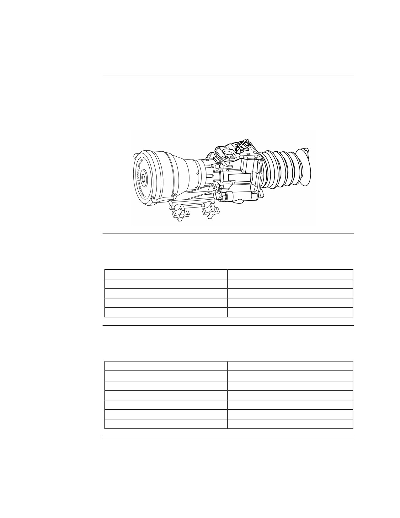
General Information
Description
The AN/PVS-17C miniature night sight (MNS) is a high performance,
compact, lightweight, monocular, night vision aiming system. The MNS
takes ambient/available light from night time sources—such as moonlight,
starlight, and sky glow—and amplifies it into a viewable image.
Physical
The MNS consists of the following physical characteristics:
Characteristics
Characteristic
Dimension/Description
Height
4.75 inches
Width
3.25 inches
Length w/eyeguard
11.375 inches
Weight w/battery
3 pounds
Operating
The MNS consists of the following operating characteristics:
Characteristics
Characteristic
Description
Operating Temperature Range
-40°F to +125.6°F (-40°C to +52°C)
Maximum Altitude
45,000 feet
Maximum Water Immersion (Fresh)
66 feet
Target Detection Range
500 meters
Magnification
4.5 times
Battery
1 AA alkaline or lithium battery
Continued on next page
MCI Course 0321B
4-18
Study Unit 4, Lesson 2
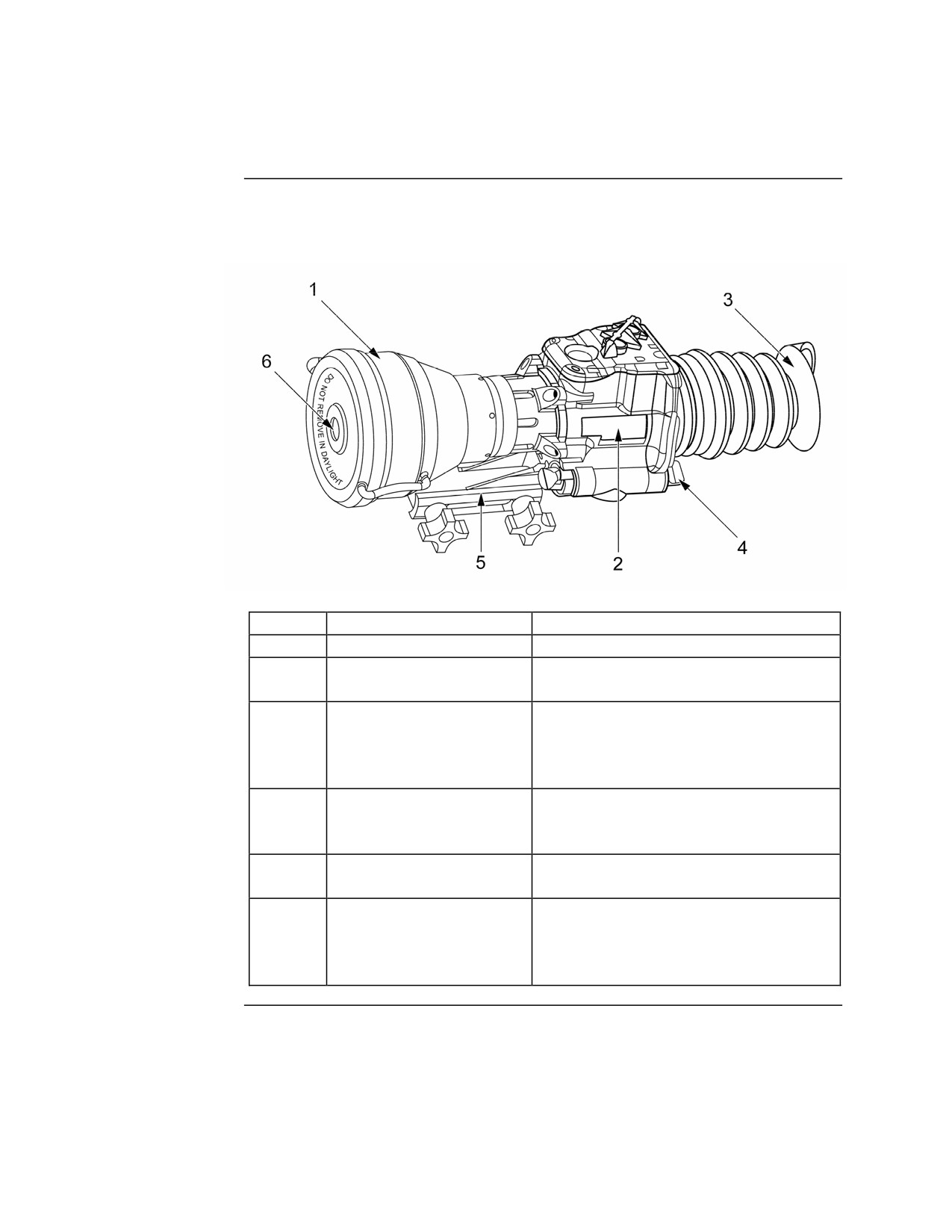
General Information, Continued
Major
The table below lists the MNS major components and their function:
Components
Item
Description
Function
1
Objective Lens
Provides magnification for imager
2
Image Intensifier
Amplifies available light into a
viewable image for the operator
3
Eyeguard
Provides protection for the eyepiece
optics, recoil protection for the
operator, and light security to within
10 meters
4
Eye Bumper (not shown)
Provides recoil protection for the
operator but no light security; used
instead of the eyeguard
5
Mount
Universal attachment that interface
between the MNS and the weapon
6
Daylight Filter
Protects the image intensifier from
bright light during limited daylight use
of the MNS for zeroing—a neutral
density
Continued on next page
MCI Course 0321B
4-19
Study Unit 4, Lesson 2
General Information, Continued
Internal Reticle The MNS contains an internal reticle that projects a red dot with an
intensified image of the viewed scene onto the eyepiece lens to provide an
aiming point for targeting. The illumination brightness of the red dot reticle
is controlled by the reticle brightness knob.
Low Battery
A yellow LED will illuminate in the eyepiece to indicate that a minimum of
Warning LED
30 minutes of battery life remains. It is located in the upper right of the
eyepiece.
MCI Course 0321B
4-20
Study Unit 4, Lesson 2
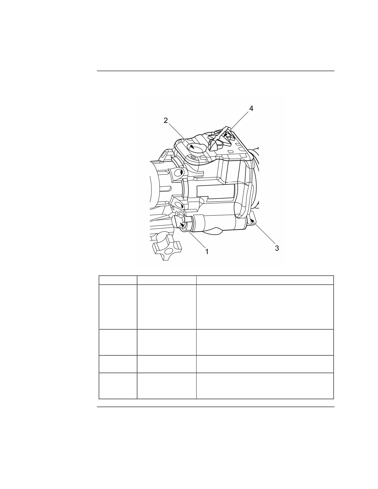
Controls
Description
The table below lists the MNS controls and their function:
Item
Control
Function
1
OFF-ON-ON
• OFF - Power is not provided to the
Selection Switch
image intensifier or reticle.
• ON - Used with the momentary button.
• ON - Continuous power to the image
intensifier and reticle.
2
Momentary
Power is applied to the image intensifier
Button
and reticle while this button is pressed and
held in.
3
Reticle
Consists of five levels of brightness to
Brightness Knob
adjust the brightness of the reticle.
4
Reticle Elevation
Used when zeroing the MNS
and Windage
Adjustment
MCI Course 0321B
4-21
Study Unit 4, Lesson 2
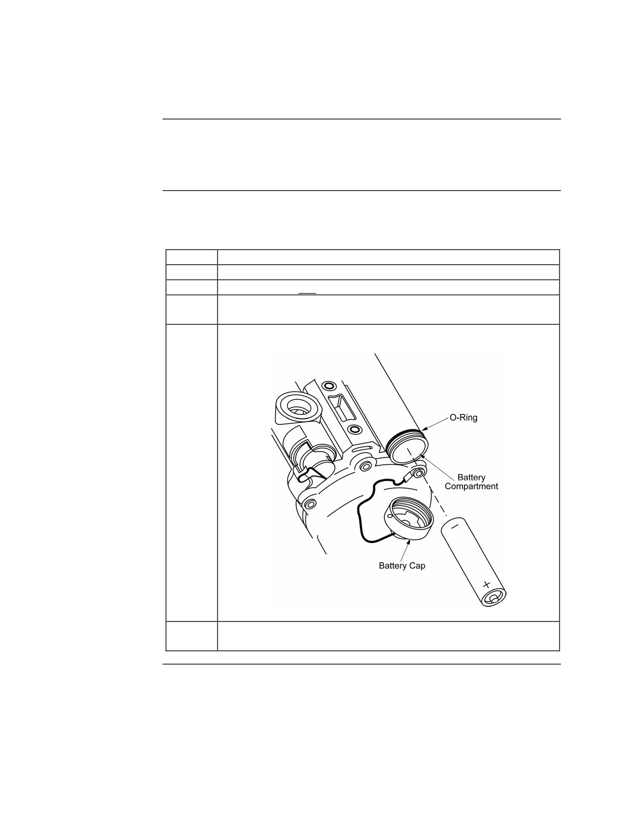
Mounting
Introduction
Make sure the M240G is in weapons condition 4 before mounting the MNS.
Avoid carrying the MNS by the eyeguard or objective lens cover. These
items may detach from the sight, causing it to drop.
Installing the
Before mounting the MNS to the M240G, you should install the battery. The
Battery
procedure for installing the battery is listed in the table below:
Step
Action
1
Make sure the objective lens cover is installed.
2
Place the OFF-ON-ON switch to the OFF position.
3
Open the battery compartment by rotating the battery cap
counterclockwise.
4
Insert the battery negative terminal first.
5
Place the battery cap on the battery compartment and rotate
clockwise until closed.
Continued on next page
MCI Course 0321B
4-22
Study Unit 4, Lesson 2
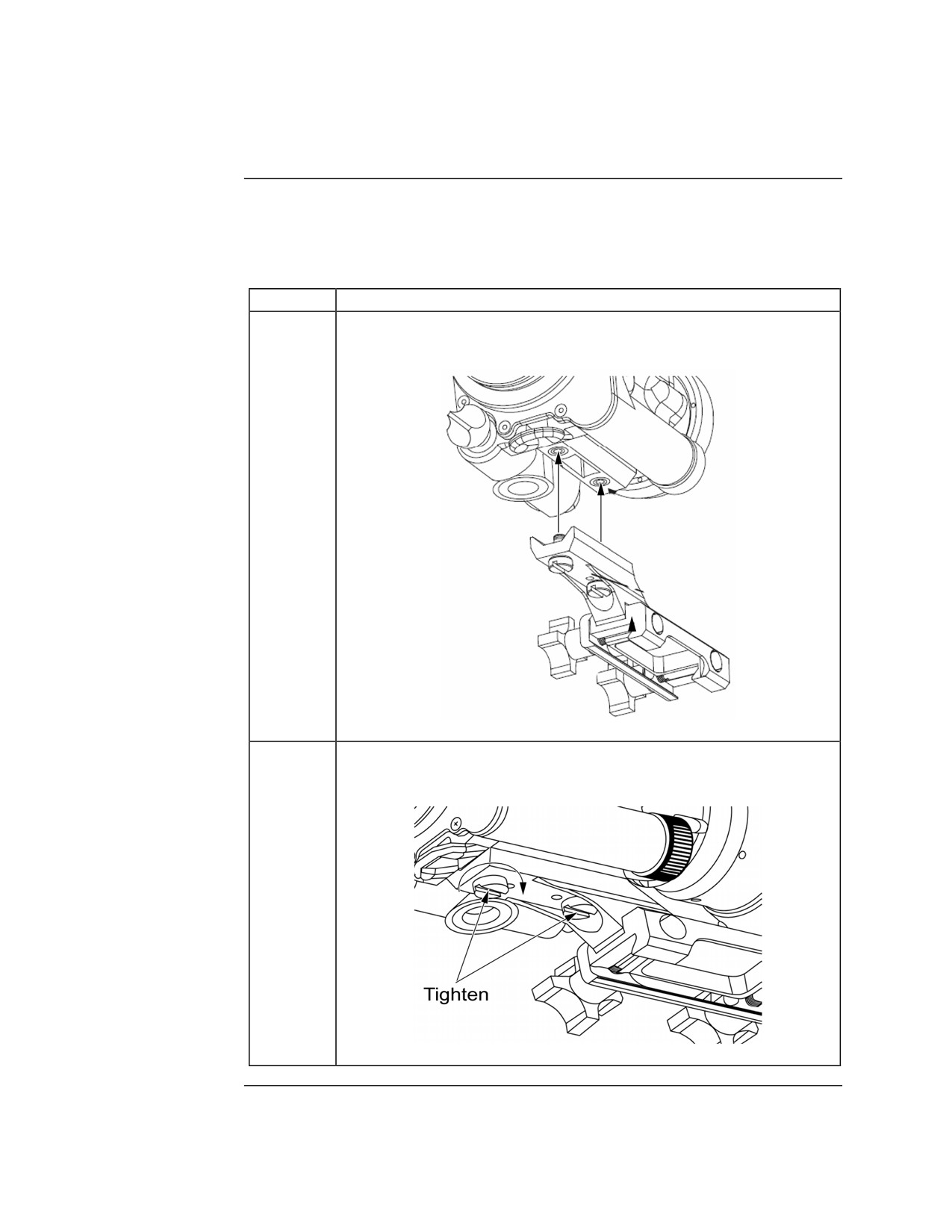
Mounting, Continued
Installing the
To mount the AN/PVS-17C to the M240G, the rail assembly mount must be
Rail Assembly
used. The procedure for mounting the rail assembly mount onto the
Mount
AN/PVS-17C is listed below:
Step
Action
1
Align the mounting screws on the rail assembly mount with the
threaded mounting holes on the bottom of the MNS.
2
Rotate the mounting screws clockwise using a flat tip
screwdriver until tight. Do not over-tighten.
Continued on next page
MCI Course 0321B
4-23
Study Unit 4, Lesson 2
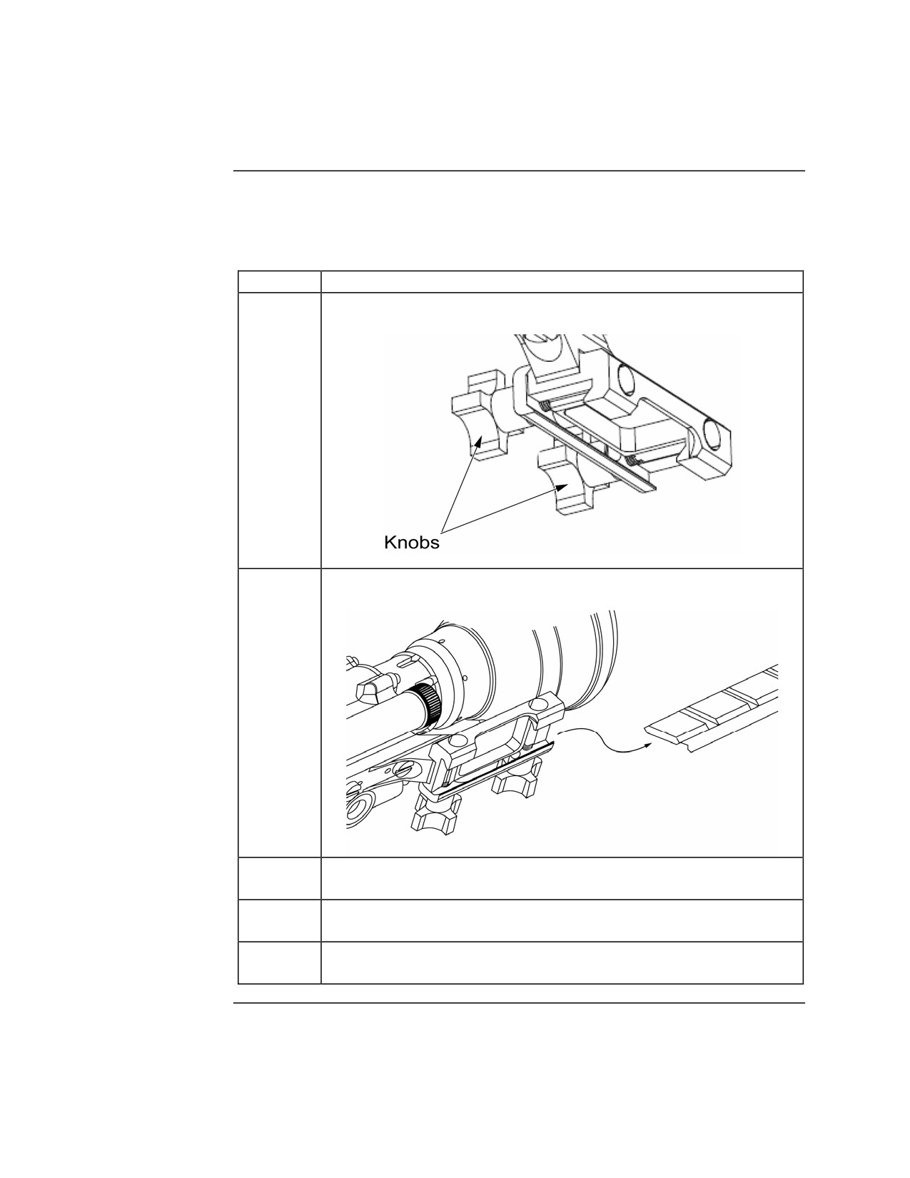
Mounting, Continued
Mounting the
The procedure for mounting the AN/PVS-17C to the M240G is listed in the
MNS to the
table below:
M240G
Step
Action
1
Loosen the two knobs.
2
Slide the rail assembly mount onto the mounting rail.
3
Move the MNS forward until the recoil stops are aligned with
the recoil slots on the rail assembly mount.
4
Check the eye relief. Adjust the MNS on the mounting rail as
needed.
5
Tighten the rear knob and then the front knob. Repeat three
more times until knobs are tight.
MCI Course 0321B
4-24
Study Unit 4, Lesson 2
Operation
Precautions
When using the MNS during night operations, carefully read and understand
the following precautions:
• The equipment’s level of performance depends upon some night light—
moonlight, starlight, sky glow, etc.—to operate.
• Night light is reduced by passing cloud cover or while operating under
trees, in building shadows, etc.
• Equipment is less effective when viewing into shadows and darkened
areas.
• Equipment’s function degrades through rain, fog, sleet, snow, or smoke.
• Equipment’s function degrades underwater in cloudy, murky water
conditions.
• Make sure the objective lens cover is installed over the objective lens
when operating the MNS during the day.
Procedure
The steps for operating the MSN when mounted to the M240G are listed in
the table below:
Step
Action
1
Assume a firing position behind the weapon.
2
Place the OFF-ON-ON selection switch to the ON position.
3
Press your eye against the eye guard.
4
Rotate the BRIGHTNESS knob until the reticle is clearly visible.
5
Adjust the eyepiece focus ring until a sharp image of the reticle
is obtained.
6
Remove your eye from the eye guard.
MCI Course 0321B
4-25
Study Unit 4, Lesson 2
Lesson 2 Exercise
Directions
Complete exercise items 1 through 6 by performing the action required.
Check your answers against those listed at the end of this lesson.
Item 1
What is the magnification of the AN/PVS-17C MNS?
a.
2.5 times
b.
3.5 times
c.
4.5 times
d.
5.5 times
Item 2
List the six main parts of the AN/PVS-17C.
•
___________________________________________________________
•
___________________________________________________________
•
___________________________________________________________
•
___________________________________________________________
•
___________________________________________________________
•
___________________________________________________________
Item 3
To use the momentary button, the OFF-ON-ON selection switch must be in
the ___________________ position.
a. OFF
b. ON
c. OFF
d. ON
Continued on next page
MCI Course 0321B
4-26
Study Unit 4, Lesson 2 Exercise
Lesson 2 Exercise, Continued
Item 4
Before opening the battery compartment, you should ensure
____________________________________________________________
____________________________________________________________
Item 5
To use the AN/PVS-17C with the M240G, the __________________ mount
must be used.
a. rail assembly
b. all purpose
c. night optic
d. receiver cover
Item 6
List the steps in order for operating the AN/PVS-17C mounted on an M240G.
•
___________________________________________________________
•
___________________________________________________________
•
___________________________________________________________
•
___________________________________________________________
•
___________________________________________________________
•
___________________________________________________________
Continued on next page
MCI Course 0321B
4-27
Study Unit 4, Lesson 2 Exercise
Lesson 2 Exercise, Continued
Answers
The table below lists the answers to the exercise items. If you have you
questions about these items refer to the reference page.
Item Number
Answer
Reference Page
1
c
4-18
2
• Objective Lens
4-19
• Image Intensifier
• Eyeguard
• Eye Bumper
• Mount
• Daylight Filter
3
b
4-21
4
The objective lens cover is installed and
4-22
the OFF-ON-ON switch is in the OFF
position.
5
a
4-23
6
• Assume a firing position behind the
4-25
weapon.
• Place the OFF-ON-ON selection
switch to the ON position.
• Press your eye against the eye
guard.
• Rotate the BRIGHTNESS knob
until the reticle is clearly visible.
• Adjust the eyepiece focus ring until
a sharp image of the reticle is
obtained.
• Remove your eye from the eye
guard.
Lesson
In this lesson, you have learned the characteristics, components, and
Summary
operation of the AN/PVS-17C miniature night sight.
Study Unit
This study unit has familiarized you with two different optic systems for use
Summary
with the M240G, allowing you to operate in periods of limited visibility or
darkness.
MCI Course 0321B
4-28
Study Unit 4, Lesson 2 Exercise
M240G MEDIUM MACHINEGUNNER
REVIEW LESSON EXAMINATION
Review Lesson
Introduction
The purpose of the review lesson examination is to prepare you for your final
examination. We recommend that you try to complete your review lesson
examination without referring to the text, but for those items (questions) you
are unsure of, restudy the text. When you finish your review lesson and are
satisfied with your responses, check your responses against the answers
provided at the end of this review lesson examination
Directions
Select the ONE answer that BEST completes the statement or that answers
the item. For multiple choice items, circle your response. For matching
items, place the letter of your response in the space provided.
Item 1
The M240G is used to support both
a. offensive and defensive operations.
b. desert and jungle operations.
c. combat and training operations.
d. Army and Marine Corps operations.
Item 2
The weight of the M240G without the mount and tripod is _______ pounds.
a.
20.6
b.
25.6
c.
26.5
d.
29.5
Item 3
The maximum effective range of the M240G against an area target is
________ meters.
a.
1400
b.
1600
c.
1800
d.
2000
Continued on next page
MCI Course 0321B
R-1
Review Lesson Examination
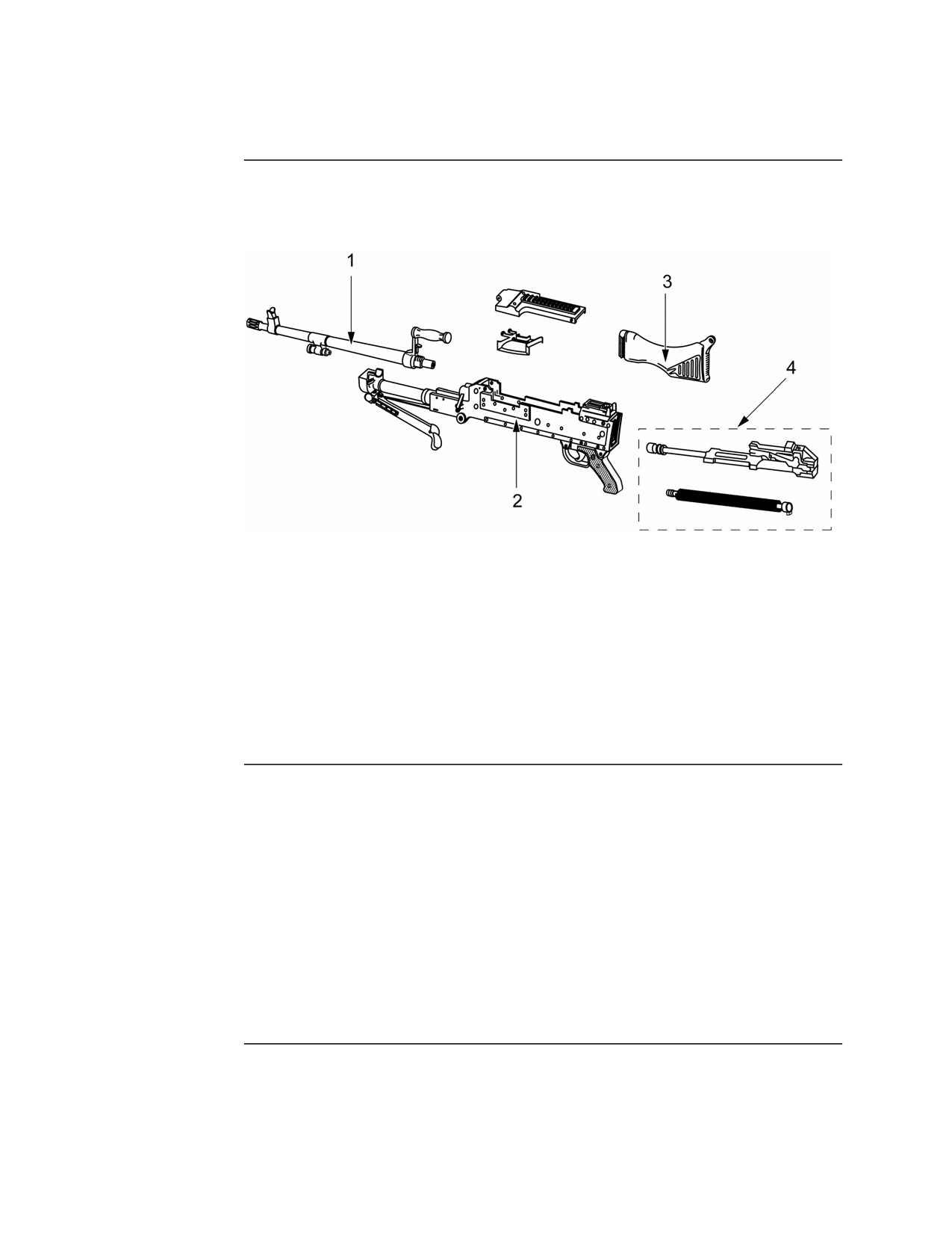
Review Lesson, Continued
Items 4
Matching: For items 4 through 7, use the illustration below to match the
Through 7
group in column 2 with its item number in column 1.
Column 1
Column 2
Item
Group
_____ 4.
1
a. Receiver
_____ 5.
2
b. Buttstock
_____ 6.
3
c. Operating
_____ 7.
4
d. Barrel
Items 8
Matching: For items 8 through 11, match the purpose in column 2 with its
Through 11
group in column 1.
Column 1
Column 2
Group
Purpose
_____ 8. Barrel group
a. Controls firing
_____ 9. Buttstock group
b. Houses the action of the weapon
_____ 10. Trigger housing group
c. Directs the projectile after firing
_____ 11. Receiver group
d. Absorbs recoil
Continued on next page
MCI Course 0321B
R-2
Review Lesson Examination
Review Lesson, Continued
Item 12
The M240G uses the ________ tripod.
a. M2
b. M3
c. M122
d. M112
Item 13
Which tool is used to clean the gas ports on the barrel and gas regulator plug?
a. Combination tool scraper and extractor
b. Scraper tool
c. Cleaning rods and attachments
d. Reamers
Item 14
In the cycle of operations for the M240G, what follows firing?
a. Chambering
b. Ejecting
c. Extracting
d. Unlocking
Item 15
When clearing the M240G, you need to raise the feed tray and
a. visually and physically inspect the chamber for ammunition.
b. have an NCO check the weapon for ammunition.
c. remove the barrel to check for ammunition.
d. physically inspect the chamber for ammunition.
Item 16
The two types of disassembly are
a. dynamic and static.
b. field and garrison.
c. combat and armory.
d. general and detailed.
Continued on next page
MCI Course 0321B
R-3
Review Lesson Examination
Review Lesson, Continued
Item 17
Detailed disassembly of the receiver group includes removing the
a. bipod assembly.
b. charging handle.
c. cover and feed tray.
d. rear sight assembly.
Item 18
When assembling the M240G, you must assemble the ________________
and __________________ before the buttstock.
a. bipod assembly; operating group
b. trigger housing group; operating group
c. trigger housing group; barrel assembly
d. tripod; flex-mount
Item 19
A function check should always be performed
a. after firing the weapon.
b. before loading the weapon.
c. after the weapon has been disassembled and assembled.
d. before mounting on the tripod.
Item 20
The first step in performing a function check for the M240G is to
a. place the safety on SAFE.
b. place the safety on FIRE.
c. pull the cocking handle to the rear.
d. open the cover.
Item 21
The M240G uses _______________________ ammunition.
a.
5.56 millimeter
b.
7.62 millimeter
c.
40 millimeter
d.
.50 caliber
Continued on next page
MCI Course 0321B
R-4
Review Lesson Examination
Review Lesson, Continued
Items 22
Matching: For items 22 through 25, match the purpose in column 2 with the
Through 25
ammunition in column 1.
Column 1
Column 2
Ammunition
Purpose
_____ 22. M80 ball
a. Practice of loading and unloading
_____ 23. M62 tracer
b. Observation of fire and signaling
_____ 24. M82 blank
c. Anti-personnel and marksmanship
_____ 25. M63 dummy
training
d. Simulated live fire
Item 26
When storing M240G ammunition outdoors for long periods, it should be
kept at least ________ inches off the deck.
a.
2
b.
4
c.
6
d.
8
Item 27
Ammunition that is heavily corroded should be
a. fired immediately.
b. returned to the manufacturer.
c. thrown away.
d. replaced with clean ammunition.
Item 28
The only cleaning agents authorized for use on the M240G are
a. CLP, RBC, and dry cleaning solvent.
b. CLP, LAW, and LSA.
c. LSA-T, RBC, and gasoline.
d. LSA-T, LAW, and JP5.
Continued on next page
MCI Course 0321B
R-5
Review Lesson Examination
Review Lesson, Continued
Item 29
The only lubricants authorized for use on the M240G are
a. CLP, RBC, LAW, and WD-40.
b. LAW, LSA, LSA-T, and WD-40.
c. CLP, LAW, LSA, and LSA-T.
d. LAW, LSA, WD-40, and LSA-T.
Item 30
When environmental temperatures are normally below 10°F, the lubricant that
should be used on the M240G is
a. CLP.
b. LSA.
c. LAW.
d. LSA-T.
Item 31
When cleaning the M240G, avoid getting lubricants or solvents
a. on wooden parts.
b. on composite or rubber parts.
c. inside the receiver.
d. on the barrel.
Item 32
The scraper tool is used to clean
a. the barrel chamber and bore.
b. the receiver.
c. the operating rod.
d. the gas regulator plug.
Item 33
The driving spring should be replaced if there are __________ or more
broken strands on a single coil or ___________ or more broken strands
anywhere on the spring.
a.
1; 3
b.
1; 4
c.
2; 3
d.
2; 4
Continued on next page
MCI Course 0321B
R-6
Review Lesson Examination
Review Lesson, Continued
Item 34
Before firing the M240G, you should
a. remove excess lubrication from the bore, chamber, barrel socket, and face
of the bolt.
b. add extra lubrication to the bore, chamber, barrel socket, and face of the
bolt.
c. remove the lubrication from the spring pin, roller, and other moving parts
of the bolt.
d. remove the lubrication from the receiver rails.
Item 35
To check the headspace on the M240G, rotate the barrel handle to the “down”
position and count the number of clicks. There should be
a.
1 to 7 clicks.
b.
2 to 7 clicks.
c.
2 to 8 clicks.
d.
3 to 6 clicks.
Item 36
When caring for the M122 tripod, inspect the
a. rear legs for expanding properly and locking in place.
b. tripod head for missing paint.
c. mil scale on the rear legs for serviceability.
d. front leg locking pin for serviceability.
Item 37
When caring for the flex-mount/T&E mechanism, be sure to
a. extend the T&E mechanism all the way to clean the upper and lower
elevating screws.
b. rotate the traversing hand wheel to ensure no clicks are heard.
c. rotate the elevating hand wheel to ensure no clicks are heard.
d. check the functioning of the pintle lock.
Continued on next page
MCI Course 0321B
R-7
Review Lesson Examination
Review Lesson, Continued
Item 38
When caring for the carrying bag, be sure to wash the bag
a. using a washing machine dry with a dryer.
b. with hot water and detergent.
c. with chlorine bleach and solvents to remove lubricant stains.
d. with cold water and mild detergent.
Item 39
To release the bipod from the receiver, press the
a. bipod latch.
b. bipod lever.
c. barrel release.
d. slide latch.
Item 40
When setting up the tripod for use, extend the rear legs until the __________
latch engages, locking the legs in place.
a. sleeve
b. leg locking
c. bipod
d. tripod
Item 41
When preparing the T&E mechanism for use with the tripod, extend the upper
and lower elevating screws so that __________________ are visible on both.
a.
1 1/2 inches
b.
2 inches
c.
2 1/2 inches
d.
2 3/4 inches
Continued on next page
MCI Course 0321B
R-8
Review Lesson Examination
Review Lesson, Continued
Items 42
Matching: For items 42 through 45, match the description in column 2 to the
Through 45
weapon condition in Column 1.
Column 1
Column 2
Condition Code
Description
_____ 42.
1
a. The bolt is forward, the safety is
_____ 43.
2
disengaged, and the feed tray is clear of
_____ 44.
3
ammunition. The cover is closed.
_____ 45.
4
b. The bolt is forward, the chamber is
empty, and the safety is disengaged.
Ammunition is on the feed tray, the
cover is closed.
c. The bolt is locked to the rear, the safety
is engaged. Ammunition is on the feed
tray, the cover is closed.
d. Does not apply to the M240G.
Item 46
To load the M240G with the cover opened, place the belt of ammunition on
the feed tray with
a. closed side of the links facing down.
b. the links removed from the belt.
c. open side of the links facing up.
d. open side of the links facing down.
Item 47
When loading the M240G with the cover closed, the bolt should be
a. forward with the safety on SAFE.
b. to the rear with the safety on SAFE.
c. forward with the safety on FIRE.
d. to the rear with the safety on FIRE.
Continued on next page
MCI Course 0321B
R-9
Review Lesson Examination
Review Lesson, Continued
Item 48
When unloading the M240G, be sure to
a. center the T&E on the traversing slide bar.
b. raise the feed tray and inspect the chamber and receiver for rounds or
links.
c. leave the bolt forward so no additional rounds are chambered.
d. leave the safety on FIRE.
Item 49
The rapid rate of fire is 200 rounds per minute which equates to firing
a.
6- to 8-round bursts with a 2- to 3-second pause.
b.
6- to 8-round bursts with a 3- to 4-second pause.
c.
10- to 12-round bursts with a 2- to 3-second pause.
d.
10- to 12-round bursts with a 3- to 4-second pause.
Item 50
Placing the rear sight in the horizontal (“down”) position is for targets at
ranges
a. greater than 1000 meters.
b. less than 1000 meters.
c. greater than 800 meters.
d. less than 800 meters.
Item 51
When adjusting the rear sight in the vertical position, the range scale has
settings from 800 (8) to 1800 (18) meters in increments of ______ meters.
a.
25
b.
50
c.
100
d.
200
Continued on next page
MCI Course 0321B
R-10
Review Lesson Examination

Review Lesson, Continued
Item 52
Sight alignment for the M240G with the rear sight in the horizontal position
consists of aligning the tip of the front sight
a. blade in the center of the peep sight aperture.
b. blade with the center of the bottom of the peep sight aperture.
c. post with the center of the rear sight groove.
d. post with the center of the peep sight aperture.
Item 53
Which illustration shows the proper sight alignment with the rear sight in the
vertical position?
a.
b.
c.
d.
Item 54
When firing from the bipod, place the
a. right hand on the stock and the left hand on the pistol grip.
b. left hand on the stock and the right hand on the pistol grip.
c. right hand under the receiver and the left hand on the pistol grip.
d. left hand under the receiver and the right hand on the pistol grip.
Continued on next page
MCI Course 0321B
R-11
Review Lesson Examination
Review Lesson, Continued
Item 55
When firing from the tripod, the ___________ hand is on the pistol grip and
the ___________________________ hand wheel.
a. right; left hand is on the traversing
b. left; right hand is on the traversing
c. right; left hand is on the elevation
d. left; right hand is on the elevation
Item 56
To change direction using the T&E mechanism, rotate the
a. traversing hand wheel front or back with the left hand.
b. traversing hand wheel front or back with the right hand.
c. elevation hand wheel left or right with the left hand.
d. elevation hand wheel left or right with the right hand.
Item 57
Barrel changes should be done every __________ minutes when firing at the
sustained rate of fire.
a.
2
b.
5
c.
10
d.
15
Item 58
To remove the barrel from the receiver, press the barrel
a. locking latch.
b. release latch.
c. locking lever.
d. release lever.
Continued on next page
MCI Course 0321B
R-12
Review Lesson Examination
Review Lesson, Continued
Item 59
After unlocking the restraining strap on the front sight assembly, use the
___________________________ to adjust the front sight blade for elevation.
a. hex end of the combination tool
b. hex end of the front sight adjusting tool
c. slotted end of the combination tool
d. slotted end of the front sight adjusting tool
Item 60
When adjusting the windage on the front sight assembly, how many clicks are
there in one complete revolution of the adjusting screws?
a.
5
b.
6
c.
8
d.
10
Item 61
When conducting a BZO for the M240G, the target is 12.7 meters away and
the rear sight is set to ________ meters.
a.
300
b.
400
c.
500
d.
800
Item 62
When conducting a field expedient zero, one full turn of the front sight blade
moves the impact of the round _______________ inches for every 100
meters.
a.
2
b.
2 1/4
c.
4
d.
4 1/4
Continued on next page
MCI Course 0321B
R-13
Review Lesson Examination
Review Lesson, Continued
Item 63
The ___________ field of view on the AN/PAS-13B has a 5 × magnification.
a. narrow
b. wide
c. day
d. night
Items 64
Matching: For items 64 through 67, match the function in column 2 with its
Through 67
component in column 1.
Column 1
Column 2
Component
Function
_____ 64. Telescope
a. Processes the thermal image for
_____ 65. Sensor assembly
display
_____ 66. Eyepiece
b. Universal attachment interface
_____ 67. Mount
between the MWTS and the weapon
c. Provides magnification of the thermal
image
d. Displays the thermal image and all
system indicators for the operator
Items 68
Matching: For items 68 through 71, match the function in column 2 with the
Through 71
control in column 1.
Column 1
Column 2
Control
Function
_____ 68. Contrast knob
a. Selects the field of view
_____ 69. Brightness knob
b. Adjusts the focus of the reticle
_____ 70. Diopter
c. Used to turn power on and off
_____ 71. FOV knob
d. Adjusts the contrast of the thermal
scene
Continued on next page
MCI Course 0321B
R-14
Review Lesson Examination
Review Lesson, Continued
Items 72
Matching: For items 72 through 75, match the function in column 2 with the
Through 75
indicator in column 1.
Column 1
Column 2
Indicator
Function
_____ 72. NOT COOL
a.
Displays when battery power is low
_____ 73. LOW BAT
b.
Indicates the selected polarity
_____ 74. WHT HOT/BLK
c.
Displays when the system has not
HOT
cooled down sufficiently
_____ 75. EMER
d. Displays when system is in
emergency mode
Item 76
The _____________________________ is used zeroing the sight and as a
tool for measuring angles in mils.
a. zeroing aim line
b. zeroing aim point
c. range gauge
d. aiming point
Item 77
When mounting the AN/PAS-13B to the M240G, align the mounting rail of
the sight with the _____________ slot from the rear of the mounting rail on
the weapon.
a. second
b. third
c. fourth
d. fifth
Item 78
To open the battery door, push in on the latch and rotate it
a. clockwise.
b. counterclockwise.
c. forward.
d. backward.
Continued on next page
MCI Course 0321B
R-15
Review Lesson Examination
Review Lesson, Continued
Item 79
When operating the AN/PAS-13B, place the eye against the eyecup and push
in to
a. activate the display.
b. power on the sight.
c. to change the field of view.
d. auto-focus the display.
Item 80
How much does the AN/PVS-17C weigh with a battery installed?
a.
2 pounds
b.
3 pounds
c.
4 pounds
d.
5 pounds
Item 81
What type of battery does the AN/PVS-17C use?
a. AAA cell
b. AA cell
c. C cell
d. D cell
Items 82
Matching: For items 82 through 85, match the function in column 2 with the
Through 85
component in column 1.
Column 1
Column 2
Component
Function
_____ 82. Objective lens
a. Provides magnification for the
_____ 83. Image intensifier
imager
_____ 84. Eyeguard
b. Protects the image intensifier
_____ 85. Daylight filter
during daylight use
c. Amplifies available light into a
viewable image
d. Provides light security to within
10 meters from the sight
Continued on next page
MCI Course 0321B
R-16
Review Lesson Examination
Review Lesson, Continued
Items 86
Matching: For items 86 through 89, match the function in column 2 with the
Through 89
control in column 1.
Column 1
Column 2
Control
Function
_____ 86. OFF-ON-ON switch
a. Provides power while it is held
_____ 87. Momentary button
in
_____ 88. Reticle brightness
b. Controls the power for the sight
_____ 89. Reticle adjustment
c. Used during zeroing to adjust
windage and elevation
d. Adjusts the reticle at five levels
Item 90
After mounting the AN/PVS-17C to the mounting rail on the M240G, you
need to check
a. safety on the weapon.
b. battery level.
c. polarity of the sight.
d. the eye relief and adjust if necessary.
Item 91
For the AN/PVS-17C to operate effectively,
a. some night light such as moonlight or starlight is needed.
b. it must be below 60º F outside.
c. it must be mounted on a weapon.
d. the objective lens cover needs to be installed.
MCI Course 0321B
R-17
Review Lesson Examination
Review Lesson, Continued
Answers
The table below lists the answers to the review lesson examination item. If
you have questions about these items, refer to the reference page.
Item Number
Answer
Reference Page
1
a
1-5
2
b
1-6
3
c
1-7
4
d
1-8
5
a
1-8
6
b
1-8
7
c
1-8
8
c
1-9
9
d
1-9
10
a
1-11
11
b
1-13
12
c
1-14
13
d
1-17
14
d
1-19
15
a
1-32
16
d
1-34
17
c
1-42
18
b
1-44
19
c
1-46
20
b
1-46
21
b
1-54
22
c
1-54
23
b
1-54
24
d
1-55
25
a
1-55
26
c
1-56
27
d
1-56
28
a
2-4
29
c
2-5
30
c
2-5
31
b
2-11
32
d
2-12
33
c
2-19
Continued on next page
MCI Course 0321B
R-18
Review Lesson Examination
Review Lesson, Continued
Answers,
continued
Item
Answer
Reference
Number
Page
34
a
2-24
35
b
2-24
36
a
2-30
37
a
2-31
38
d
2-32
39
a
3-4
40
a
3-7
41
a
3-9
42
c
3-20
43
d
3-20
44
b
3-20
45
a
3-20
46
d
3-21
47
c
3-21
48
b
3-22
49
c
3-30
50
d
3-31
51
c
3-32
52
a
3-32
53
b
3-33
54
b
3-34
55
a
3-35
56
a
3-35
57
c
3-37
58
a
3-37
59
d
3-49
60
c
3-50
61
c
3-51
62
d
3-53
63
a
4-5
Continued on next page
MCI Course 0321B
R-19
Review Lesson Examination
Review Lesson, Continued
Answers,
continued
Item
Answer
Reference
Number
Page
64
c
4-5
65
a
4-5
66
d
4-5
67
b
4-5
68
d
4-6
69
c
4-6
70
b
4-6
71
a
4-6
72
c
4-7
73
a
4-7
74
b
4-7
75
d
4-7
76
a
4-10
77
c
4-11
78
b
4-12
79
a
4-13
80
b
4-18
81
b
4-18
82
a
4-19
83
c
4-19
84
d
4-19
85
b
4-19
86
b
4-21
87
a
4-21
88
d
4-21
89
c
4-21
90
d
4-24
91
a
4-25
MCI Course 0321B
R-20
Review Lesson Examination