NATOPS FLIGHT MANUAL NAVY MODEL AV--8B/TAV--8B 161573 AND UP AIRCRAFT (2008) - page 14
A1-AV8BC-410-100
011 00
Change 6
Page 4
23. The annunciator light controller will turn on
black and white flag indication. The indicator is
the OXY caution lights and the MASTER
mechanically reset by pressing the indicator face.
CAUTION lights when the oxygen monitor
assembly senses that oxygen concentration has
30. OXY Caution Lights. The OXY caution lights,
fallen below a safe minimum or the OBOGS
located on the caution/advisory indicator light
overtemperature switch senses temperature greater
assembly, and rear caution/advisory indicator light
than 250°F (121oC).
assembly, are dual lamp, indicator lights.
24. SYSTEM CONTROLS AND INDICATORS.
31. The OXY caution lights are controlled by the
System controls and indicators are described in
oxygen monitor assembly or OBOGS
paragraphs below.
overtemperature switch, through the
warning/caution/advisory lighting system.
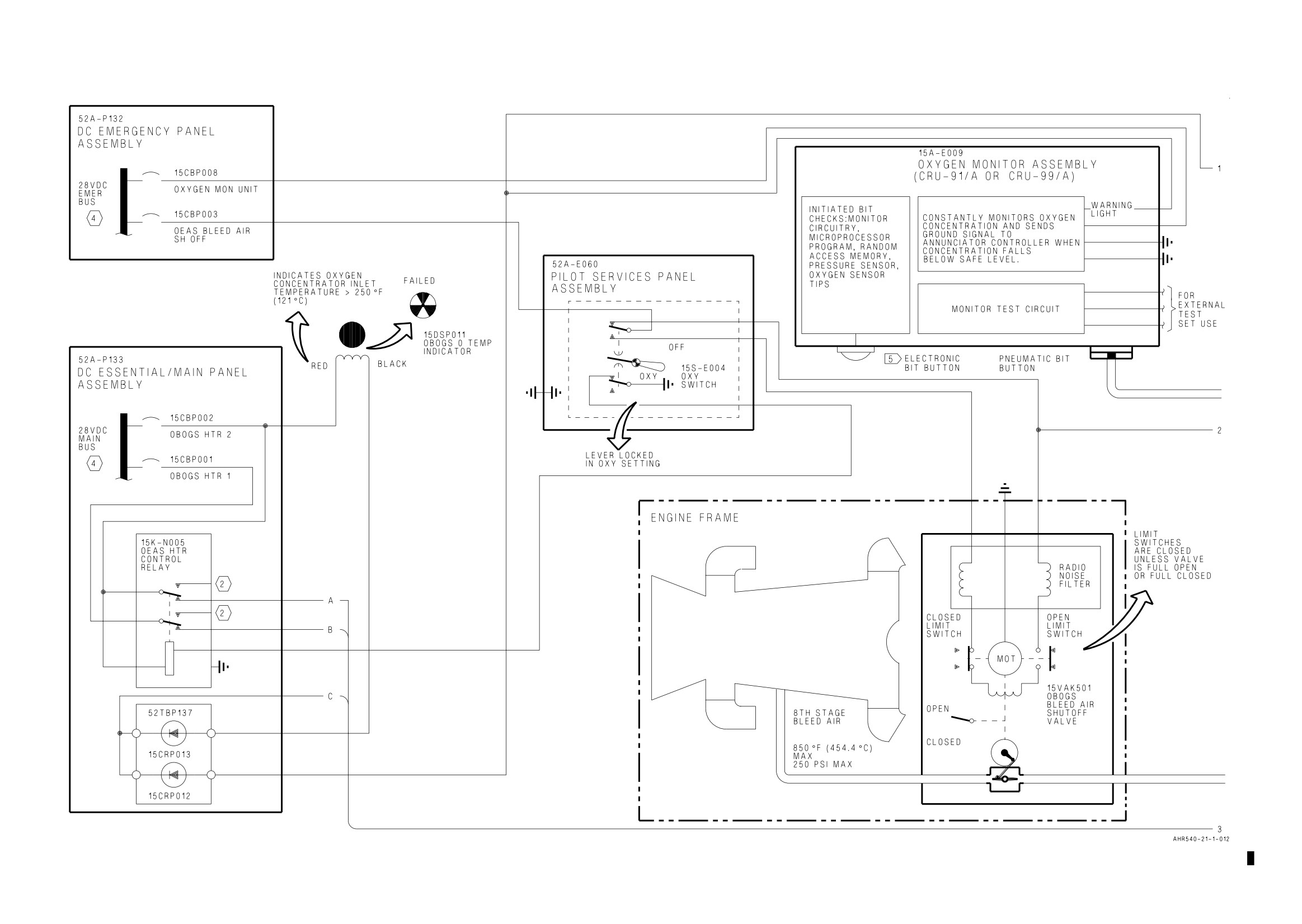
25. OXY Switch. The OXY switch, located on the
pilot services panel assembly, is a two pole, double
32. OEAS Htr Control Relay. The OEAS htr
throw, lever lock toggle switch. The switch has two
control relay, located on the distribution panel
positions; OFF and OXY. The switch is locked in
assembly, is a two pole, double throw, 10 amperes,
the OXY position.
permanent magnet drive, armature relay.
26. With the switch in the OFF position, the
33. The relay is controlled by the OXY switch.
following occurs:
With the relay energized, main 28vdc power is
applied to the two heater circuits in the oxygen
a. A ground is removed to deenergize the OEAS
concentrator. With the relay deenergized, main
htr control relay.
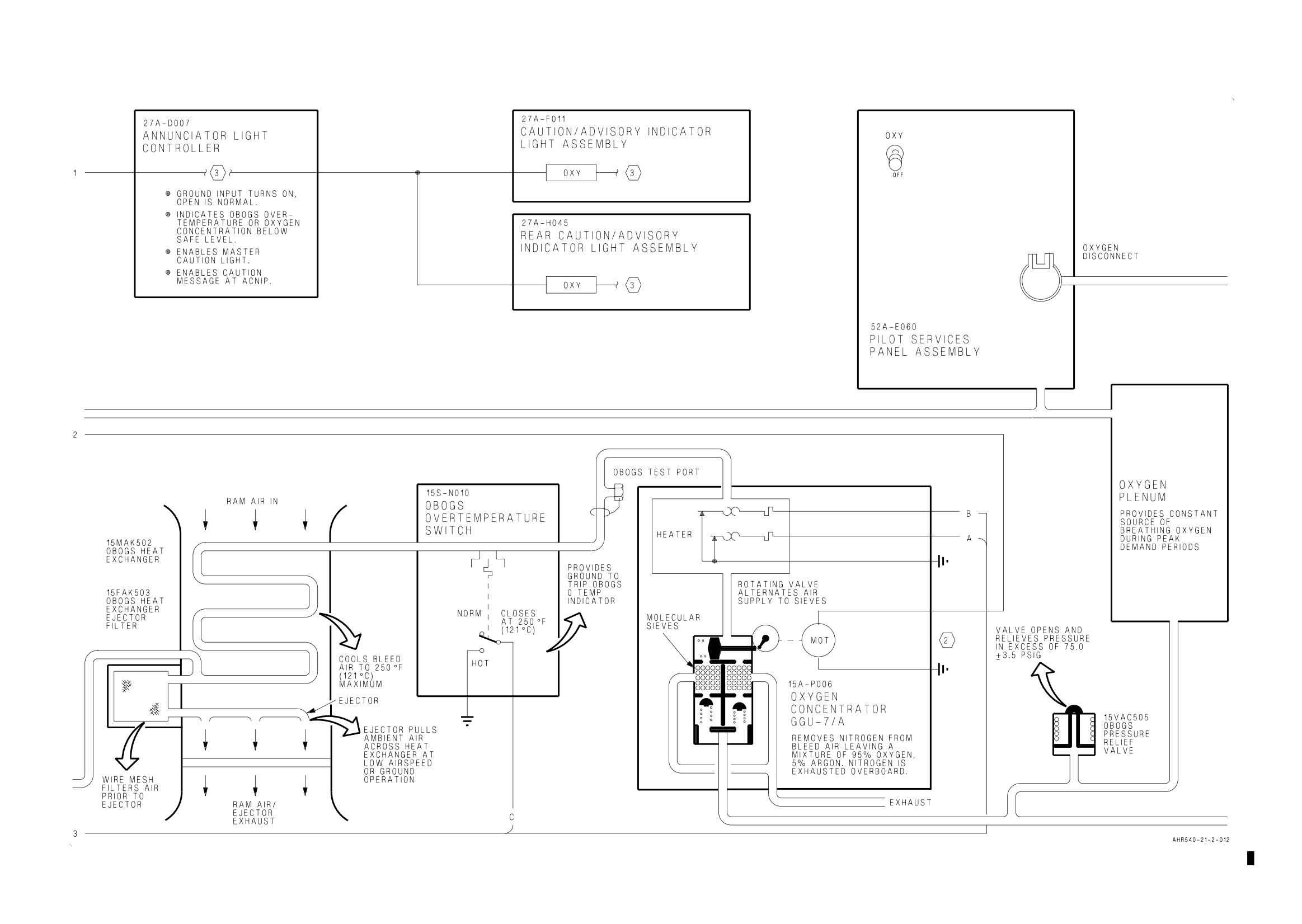
28vdc power is removed from the concentrator
heater circuits.
b. Emergency 28vdc power is removed from the
open contact of the OBOGS bleed air shutoff valve.
34. OXY Shutoff Valve. The OXY shutoff valve
located on the rear pilot services panel assembly, is
c. Emergency 28vdc power is applied to the
an in-line, mechanical, shutoff valve. The valve has
close contact of the OBOGS bleed air shutoff valve.
two positions; ON and OFF.
27. With the switch in the OXY position, the
35. With the OXY shutoff valve set to ON, oxygen
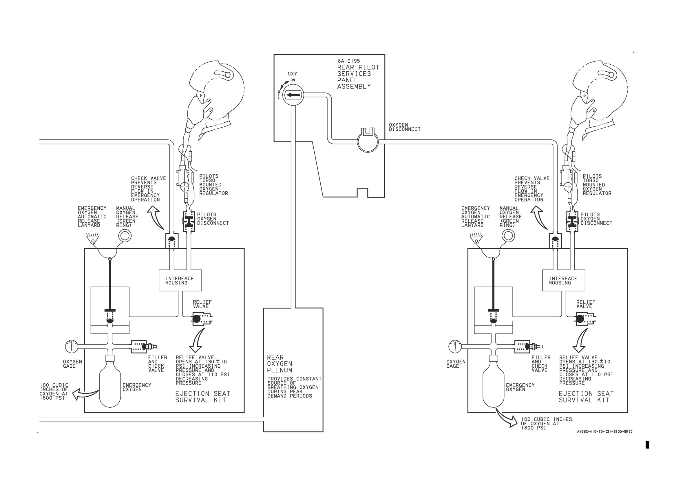
following occurs:
is provided to the rear oxygen disconnect.
a. A ground is applied to energize the OEAS
36. OPERATION.
htr control relay.
37. COMPONENT OPERATION.
b. Emergency 28vdc power is removed from the
close contact of the OBOGS bleed air shutoff valve.
38. OBOGS Bleed Air Shutoff Valve. The OBOGS
c. Emergency 28vdc power is applied to the
bleed air shutoff valve is located in door 11R. The
open contact of the OBOGS bleed air shutoff valve.
valve is electrically controlled and electrically
actuated.
28. OBOGS O Temp Indicator. The OBOGS O
TEMP indicator, located on the oxygen
39. The valve is driven open or closed by an electric
concentrator shelf, is a fault locating, flag indicating
motor in response to electrical signals controlled by
mechanical reset indicator. The indicator provides a
the OXY switch. Emergency 28vdc power is applied
visual indication when oxygen concentrator inlet
to the open or closed contacts. The valve motor
temperature exceeds 250°F (121oC).
moves as required, driving the actuator which
moves the valve butterfly.
29. When oxygen concentrator GGU-7/A inlet
temperature exceeds 250°F (121oC), the OBOGS
40. The motor has limit switches to prevent valve
overtemperature switch closes and provides a
motor overrun. When the valve butterfly has
ground to allow main 28vdc power to be applied to
reached its fully open or fully closed limit, the
the indicator coil. The coil trips the indicator from
associated limit switch is mechanically opened and
the normal, all black indication to the fault locating,
electrical power is removed from the motor.
A1-AV8BC-410-100
011 00
Change 6
Page 5
41. The valve has an external position indicator to
48. When the switch contact opens at a
allow a visual indication of the valve position. The
temperature below 250°F (121oC), the following
indicator is driven by the actuator. It is visible on
occurs:
the valve housing.
a. A ground signal is removed to remove main
42. OBOGS Heat Exchanger. The OBOGS heat
28vdc power from the OBOGS O temp indicator
exchanger is located at the right forward nozzle
coil.
fairing, in door 13R. Hot engine bleed air passes
b. A ground signal is removed from the
through the heat exchanger core. Ram air, which is
annunciator controller to disable the OXY caution
forced across the heat exchanger core by aircraft
lights.
forward motion, absorbs the heat and is exhausted
overboard through the mixer/diffuser duct.
49. OBOGS Pressure Relief Valve. The OBOGS
pressure relief valve is located in the nose landing
43. During low speed, vertical flight, or ground
gear wheelwell, in the product gas delivery line. The
operation, ram air is pulled across the heat
relief valve is threaded into one end of a tee. If
exchanger core. An ejector nozzle in the heat
OBOGS product gas pressure exceeds 75.0±3.75 psi,
exchanger directs some of the hot engine bleed air
the relief valve will open and relieve excess
overboard through the mixer/diffuser duct. The
pressure.
ejected hot air causes a suction which pulls ram air
in across the heat exchanger core.
50. Oxygen Concentrator GGU-7/A. The oxygen
concentrator GGU-7/A is located in door 61. Cooled,
44. OBOGS Heat Exchanger Ejector Filter. The
pressure regulated engine bleed air is alternately
OBOGS heat exchanger ejector filter is installed in
directed through one of two molecular sieve beds in
the OBOGS heat exchanger. Engine bleed air is
the concentrator by a rotary valve. One bed absorbs
filtered before passing through the OBOGS heat
nitrogen and other contaminants and passes an
exchanger ejector nozzle.
oxygen rich gas mixture to the cockpit for
consumption. The other bed is simultaneously
45. Mixer/Diffuser Duct. The mixer/diffuser duct
purged of nitrogen and other contaminants which
is located in the right forward nozzle fairing, aft of
have been absorbed. The cycle is repeated from
the OBOGS heat exchanger. Hot air from the
sieve bed to sieve bed 12 times per minute. Purging
OBOGS heat exchanger ejector nozzle is ejected
is done by back flushing the sieve beds with some of
into the mixer/diffuser duct. The suction created
the oxygen rich gas mixture.
pulls ram air in across the heat exchanger core. The
ejector air and ram air pass through the
51. The temperature control circuit uses electrical
mixer/diffuser duct and are exhausted overboard.
signals from an air temperature sensor, shroud
temperature sensor, and temperature controller to
46. OBOGS Overtemperature Switch. The OBOGS
control an air heater. The air heater raises the
overtemperature switch is installed in a duct in door
temperature of the air for best oxygen concentrator
61. A bimetallic temperature device senses an
GGU-7/A operation.
excessive temperature. The bimetallic properties
allow the device to expand and compress to actuate
52. Before the absorption process, the air passes
the switch.
through an inlet filter and pressure reducer. After
the absorption process, the oxygen rich gas is stored
in a plenum, providing a constant supply for
47. The switch is calibrated to close its contact at
delivery to the cockpit.
250°F (121oC). When the switch contact closes, the
following occurs:
53. Oxygen Plenum. The oxygen plenum is located
on the ejection seat bulkhead, in back of the
a. A ground signal is provided to allow main
ejection seat. The plenum stores a supply of oxygen
28vdc power to energize the OBOGS O temp
rich gas from the oxygen concentrator GGU-7/A, for
indicator coil.
peak demand use. The plenum also allows the
oxygen rich gas temperature to stabilize to cockpit
b. A ground signal is applied to the annunciator
temperature. An air duct, near the plenum, directs
controller to enable the OXY caution lights.
cockpit air around the plenum.
A1-AV8BC-410-100
011 00
Change 6
Page 6
54. Rear Oxygen Plenum. The rear oxygen plenum
(RAM), the pressure sensor, and the oxygen sensor
is located on the rear ejection seat bulkhead, in
tips.
back of the ejection seat. The plenum stores a
supply of rich gas from the oxygen concentrator
60. During operation in low ambient temperatures,
GGU-7/A for peak demand use. The plenum also
the monitor has a built in circuit heater. This allows
allows the oxygen rich gas temperature to stabilize
rapid warm up of the monitor.
to cockpit temperature. An air duct, near the
plenum, directs rear cockpit air around the plenum.
61. Oxygen Disconnect. The oxygen disconnect is
located inboard of the pilot services panel assembly.
55. Oxygen Monitor Assembly CRU-91/A or
The disconnect provides the interface between the
CRU-99/A. The oxygen monitor assembly is located
crewmembers personal equipment and the OBOGS.
in the cockpit, on the left side of the ejection seat
The oxygen disconnect is connected to the ejection
bulkhead. The monitor receives and analyzes a
seat survival kit. The crewmember connects his
sample of the oxygen rich gas. If analysis shows the
personal equipment to the survival kit.
gas to have a low oxygen concentration, a signal is
provided to the warning/caution/advisory lighting
62. Rear Oxygen Disconnect. The rear oxygen
system.
disconnect is located inboard of the rear pilot
services panel assembly. The disconnect provides
56. The oxygen concentration of the breathing gas
the interface between the crewmembers personal
delivered to the pilot ranges from approximately 29
equipment and the OBOGS. The oxygen disconnect
percent at sea level to approximately 94 percent at
is connected to the ejection seat survival kit. The
50,000 feet. The higher oxygen concentration at
crewmember connects his personal equipment to
higher altitudes is required to overpower the lower
the survival kit.
ambient pressure at high altitudes.
63. OBOGS Test Port. The OBOGS test port is
57. The monitor analyzes the oxygen rich gas by
located in the main landing gear wheelwell. The test
passing a sample of the gas over an oxygen sensor.
port allows a ground air source to be used for
The sensor is an electrochemical device which is
ground testing of the OBOGS. During ground test,
sensitive to partial pressure oxygen. An electrical
the air source bypasses the OBOGS bleed air
bias voltage and temperature compensating circuits
shutoff valve, OBOGS heat exchanger, OBOGS and
provide an output voltage which is proportional to
OBOGS overtemperature switch.
the partial pressure oxygen in the gas sample. If the
oxygen concentration is out of limits, the monitor
will provide a warning signal.
64. SYSTEM OPERATION.
58. On the CRU-91/A, a BIT button is provided.
65. Normal Operation. In normal operation, hot
The BIT button, when pressed, vents OBOGS gas,
engine bleed air passes through the OBOGS bleed
creating a lower pressure in the sensor cavity. This
air shutoff valve (figure 1) to the OBOGS heat
pulls ambient air into the sensor cavity. Since the
exchanger. An ejector in the heat exchanger directs
oxygen concentration of ambient air is less than the
some of the high pressure engine bleed air
minimum required, the oxygen monitor assembly
overboard, pulling ram air through the heat
CRU-91/A will provide a warning signal.
exchanger. Heat from the engine bleed air is
absorbed by the ram air, reducing air temperature.
59. On the CRU-99/A, two BIT buttons are
Heated ram air and ejector air are exhausted
provided. A pneumatic BIT button and an
overboard through the mixer/diffuser duct.
electronic BIT button. The pneumatic BIT button,
when pressed, vents OBOGS gas, creating a lower
66. The conditioned air is directed to the OBOGS
pressure in the sensor cavity. This pulls ambient air
pressure relief valve. The relief valve will limit
into the sensor cavity. Since the oxygen
system pressure to 75.0±3.75 psig.
concentration of ambient air is less than the
minimum required, the monitor will provide a
warning signal. The electronic BIT button when
67. An overtemperature switch provides warning to
pressed, initiates a BIT similar to the automatic
the pilot when conditioned air temperatures exceed
power-up BIT. The BIT checks monitory circuitry,
operating limits of the oxygen concentrator
the microprocessor program, random access memory
GGU-7/A.
A1-AV8BC-410-100
011 00
Change 6
Page 7
68. The oxygen concentrator GGU-7/A removes
70. Breathing gas is routed to the rear cockpit
nitrogen and other contaminants from the
through the survival kit and torso mounted oxygen
conditioned air, leaving an oxygen rich breathing
regulator to the crewmember.
gas mixture. Nitrogen and other contaminants are
purged from the concentrator and exhausted
71. Emergency Operation. A 15 minute supply of
overboard.
oxygen is stored in an emergency oxygen cylinder in
the ejection seat survival kit in both the cockpit and
69. The oxygen rich gas mixture is routed to the
rear cockpit (figure 1). The emergency oxygen
oxygen plenum in the cockpit and the rear oxygen
supply can be activated manually, by pulling the
plenum in the rear cockpit. The plenums store the
manual emergency oxygen control (green ring), or
mixture for peak demand periods and provide
automatically on ejection. A check valve prevents
temperature stabilization. A sample of the mixture
loss of oxygen pressure to the OBOGS when
is supplied to the oxygen monitor assembly, which
emergency oxygen is actuated.
warns the pilot if oxygen concentration falls below a
safe limit. The breathing gas mixture flows from the
72. The OBOGS and emergency oxygen are not
oxygen plenum to the oxygen disconnect, inboard of
related in any way, except they share a common
the pilot services panel. Breathing gas is then
manifold in each ejection seat survival kit.
routed to the cockpit through the survival kit and
torso mounted oxygen regulator to the crewmember.
A1-AV8BC-410-100
011 00
Change 7
Page 8
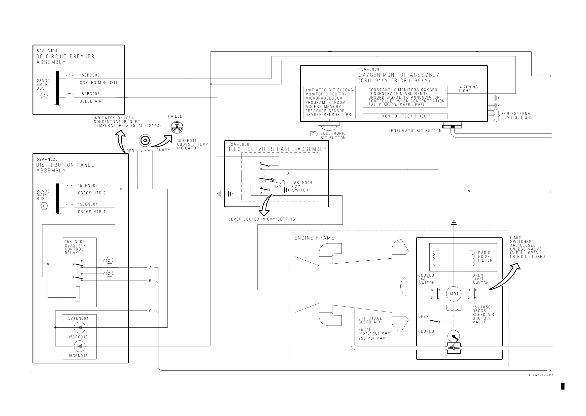
Figure 1. On-Board Oxygen Generating System Simplified Schematic-162747; ALSO 162963 THRU 163861 BEFORE AV8AFC-416 (Sheet 1)
Figure 1.
Figure 1.
A1-AV8BC-410-100
011 00
Change 7
Page 9
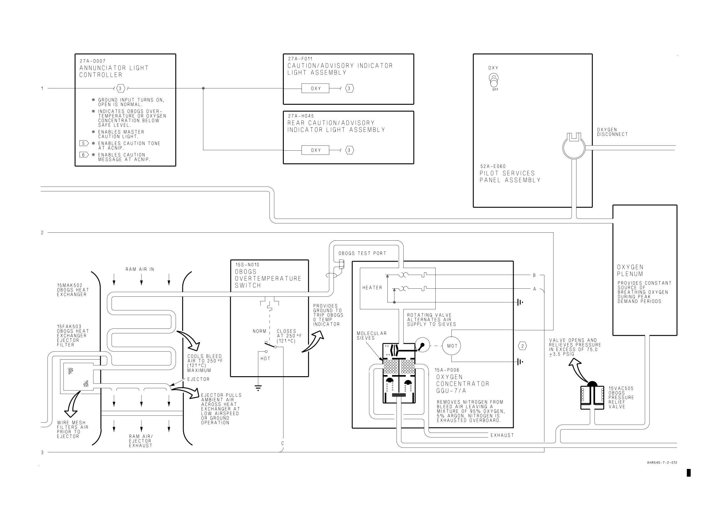
Figure 1. On-Board Oxygen Generating System Simplified Schematic-162747; ALSO 162963 THRU 163861 BEFORE AV8AFC-416 (Sheet 2)
Figure 1.
Figure 1.
A1-AV8BC-410-100
011 00
Change 7
Page 10
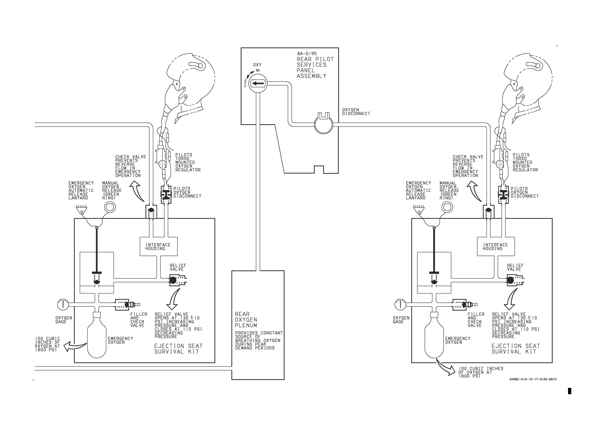
Figure 1. On-Board Oxygen Generating System Simplified Schematic-162747; ALSO 162963 THRU 163861 BEFORE AV8AFC-416 (Sheet 3)
Figure 1.
Figure 1.
A1-AV8BC-410-100
011 00
Change 7
Page 11
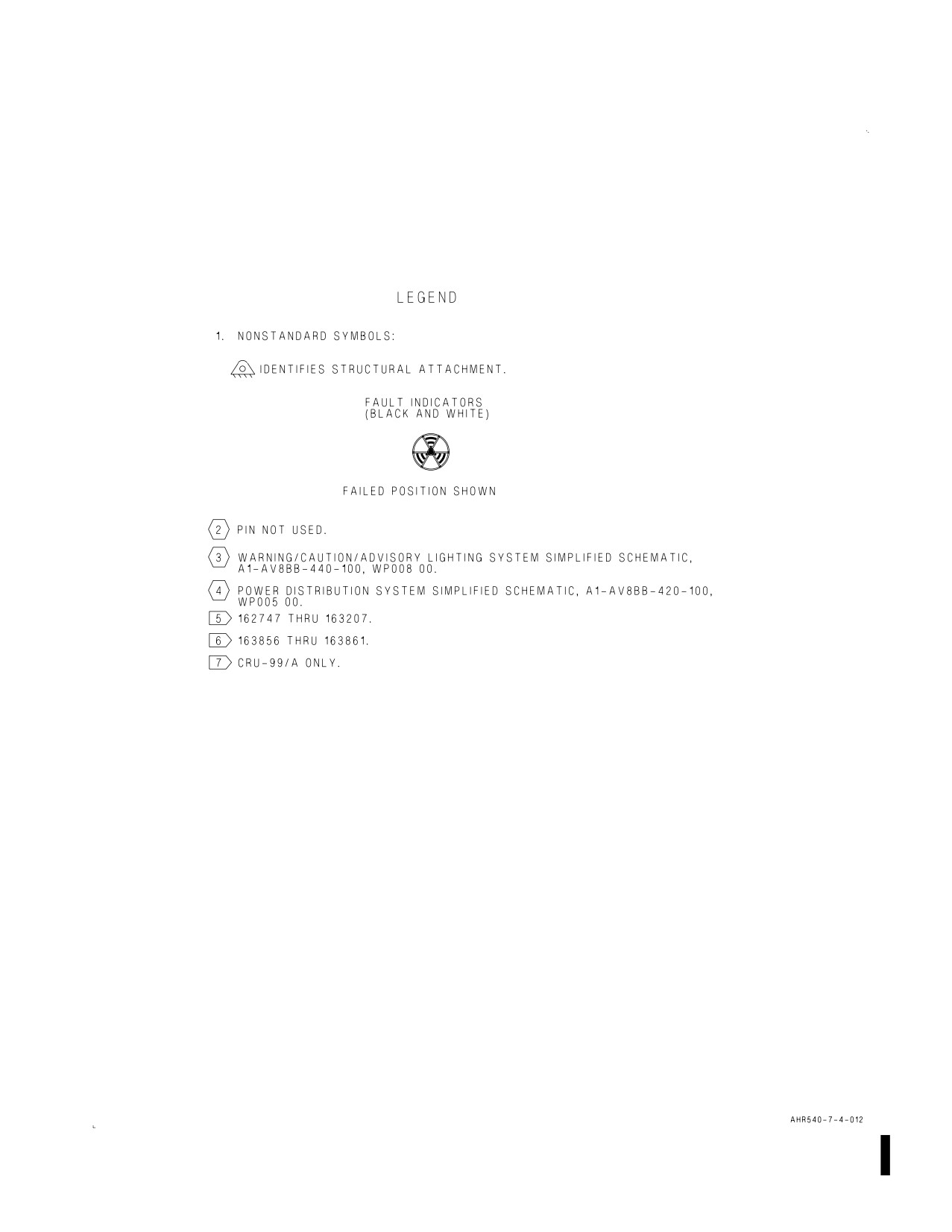
Figure 1. On-Board Oxygen Generating System Simplified Schematic-162747; ALSO
162963 THRU 163861 BEFORE AV8AFC-416 (Sheet 4)
A1-AV8BC-410-100
011 00
Change 7
Page 12
Figure 2. On-Board Oxygen Generating System Simplified Schematic-164113 AND UP; ALSO 162963 THRU 163861 AFTER AV8AFC-416 (Sheet 1)
Figure 2.
Figure 2.
A1-AV8BC-410-100
011 00
Change 7
Page 13
Figure 2. On-Board Oxygen Generating System Simplified Schematic-164113 AND UP; ALSO 162963 THRU 163861 AFTER AV8AFC-416 (Sheet 2)
Figure 2.
Figure 2.
A1-AV8BC-410-100
011 00
Change 7
Page 14
Figure 2. On-Board Oxygen Generating System Simplified Schematic-164113 AND UP; ALSO 162963 THRU 163861 AFTER AV8AFC-416 (Sheet 3)
Figure 2.
Figure 2.
A1-AV8BC-410-100
011 00
Change 7
Page 15/(16 blank)
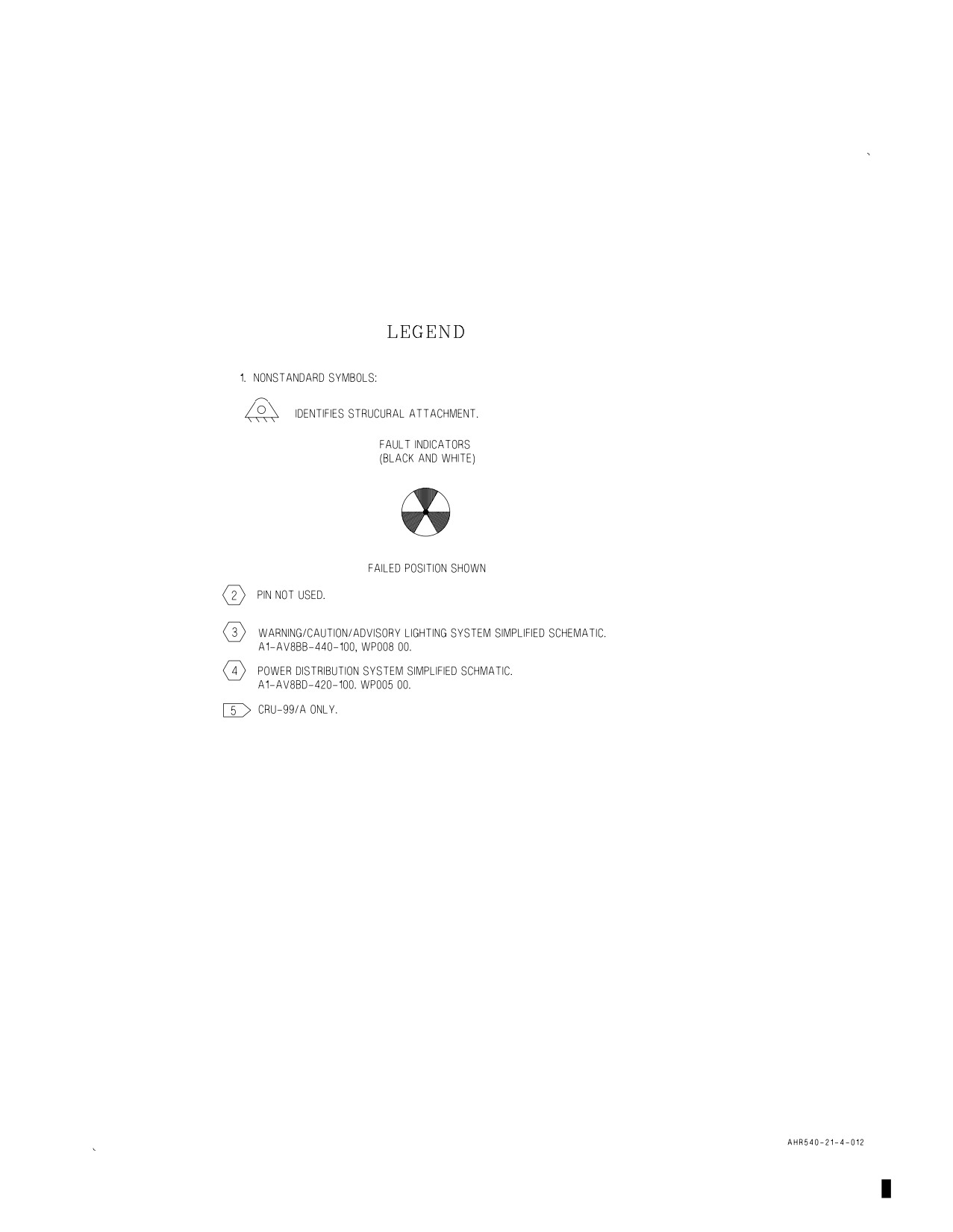
Figure 2. On-Board Oxygen Generating System Simplified Schematic-164113 AND UP;
ALSO 162963 THRU 163861 AFTER AV8AFC-416 (Sheet 4)

A1-AV8BC-410-100
012 00
Change 7 - 15 May 2004
Page 1
ORGANIZATIONAL MAINTENANCE
PRINCIPLES OF OPERATION
COMPONENT LOCATOR
ON-BOARD OXYGEN GENERATING SYSTEM
Reference Material
Environmental Control Systems
A1-AV8BC-410-100
Description and Operation - On-Board Oxygen Generating System
WP011 00
Alphabetical Index
Subject
Page No.
On-Board Oxygen Generating System Component Locator, Figure 1
2
System Components
1
Record of Applicable Technical Directives
Type/
Date
Date
Title and ECP or RAMEC No.
Remarks
Number
Incorp.
AV8AFC-416
— TAV-8B Polyimide Wire Replacement/
15 May 04
—
Power Wire Separation (ECP MDA-AV8B-
0277)
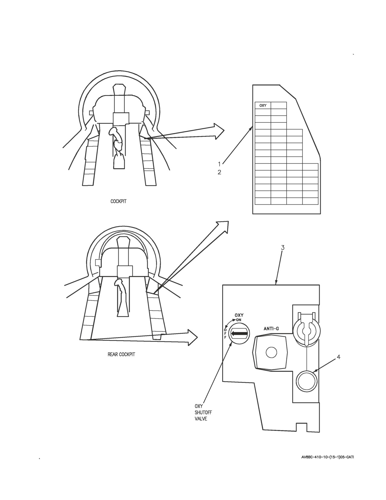
1. SYSTEM COMPONENTS.
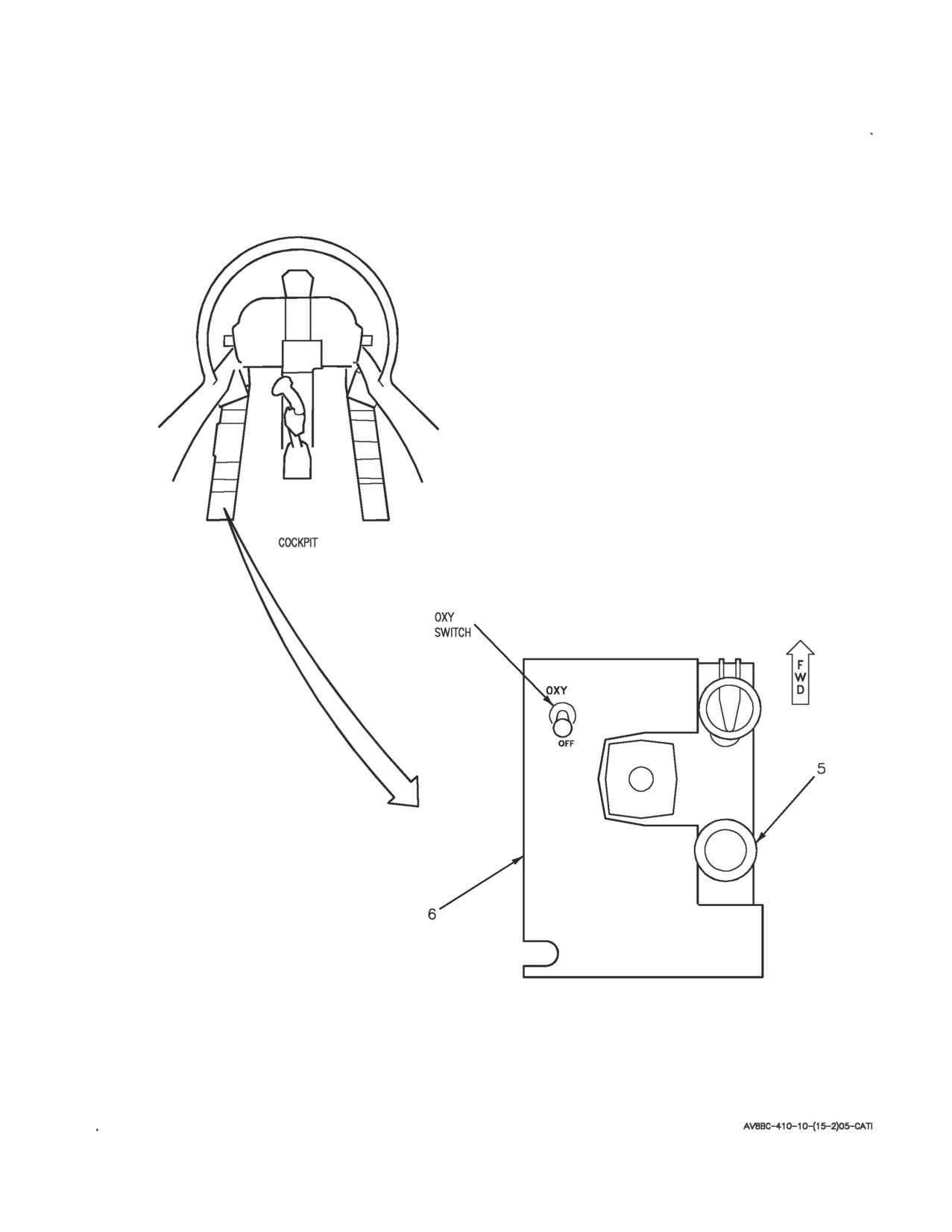
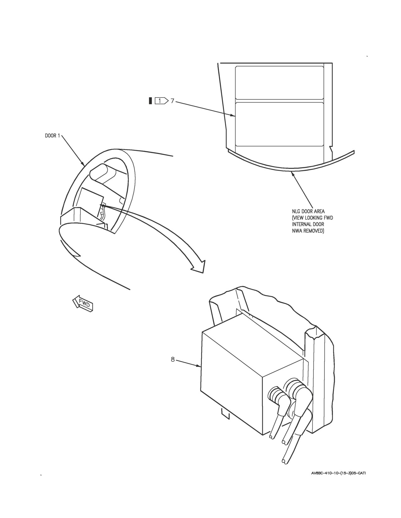
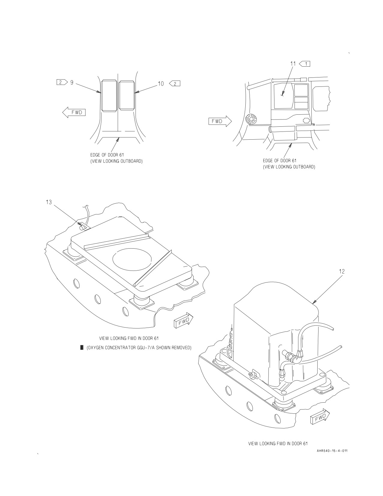
2. System components are shown in figure 1. For
description and operation of the On-Board Oxygen
Generating System, refer to WP011 00.
A1-AV8BC-410-100
012 00
Page 2
Figure 1. On-Board Oxygen Generating System Component Locator (Sheet 1)
A1-AV8BC-410-100
012 00
Page 3
Figure 1. On-Board Oxygen Generating System Component Locator (Sheet 2)
A1-AV8BC-410-100
012 00
Page 4
Figure 1. On-Board Oxygen Generating System Component Locator (Sheet 3)
A1-AV8BC-410-100
012 00
Change 2
Page 5
Figure 1. On-Board Oxygen Generating System Component Locator (Sheet 4)
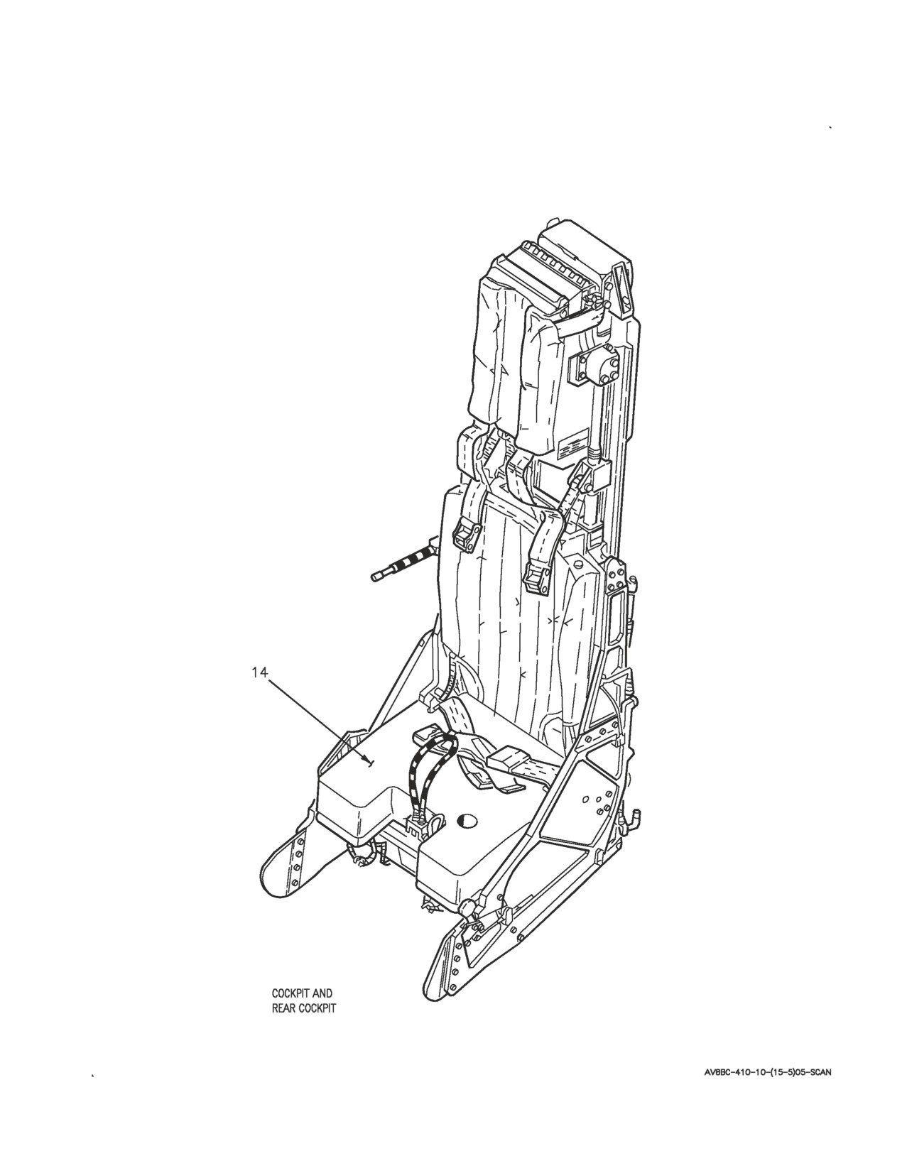
A1-AV8BC-410-100
012 00
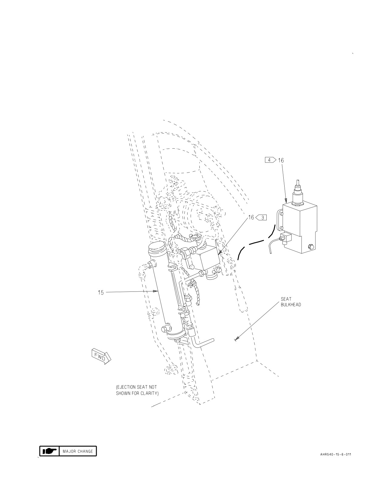
Page 6
Figure 1. On-Board Oxygen Generating System Component Locator (Sheet 5)
A1-AV8BC-410-100
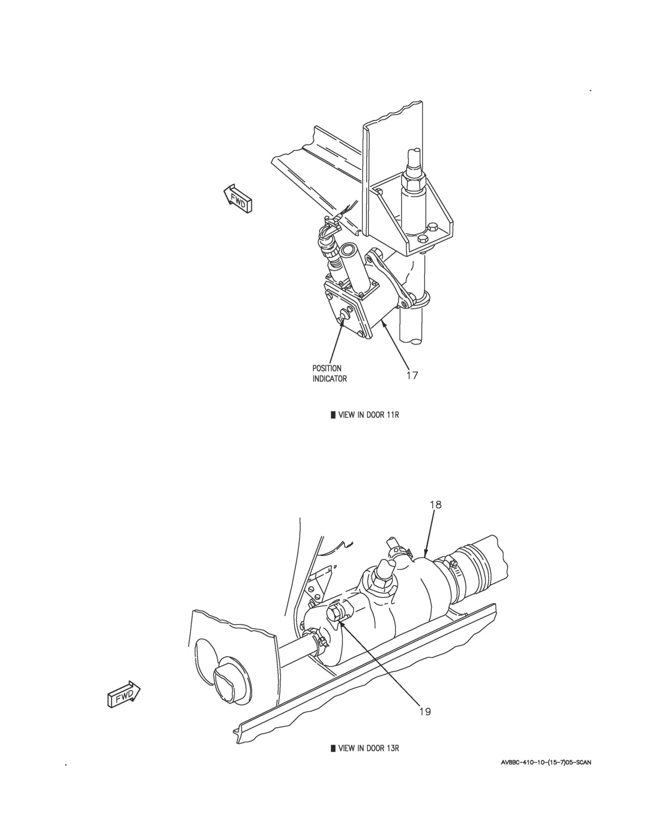
012 00
Change 5
Page 7
Figure 1. On-Board Oxygen Generating System Component Locator (Sheet 6)
A1-AV8BC-410-100
012 00
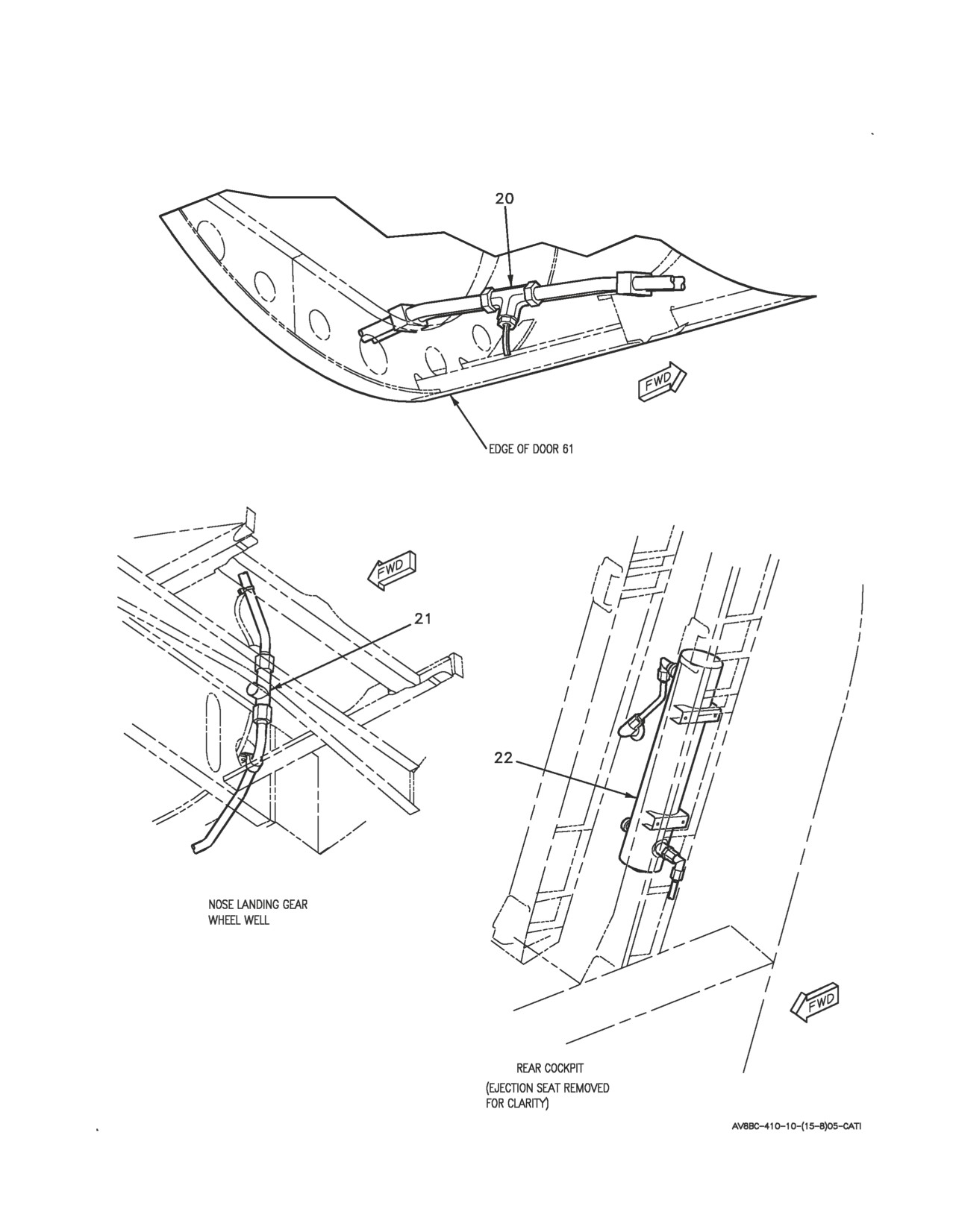
Page 8
Figure 1. On-Board Oxygen Generating System Component Locator (Sheet 7)
A1-AV8BC-410-100
012 00
Page 9
Figure 1. On-Board Oxygen Generating System Component Locator (Sheet 8)
A1-AV8BC-410-100
012 00
Change
5
Page
10
Nomenclature
Index No.
Ref Des
ANNUNCIATOR LIGHT CONTROLLER
8
27A-D007
CAUTION/ADVISORY INDICATOR LIGHT
1
27A-F011
ASSEMBLY
1
DC CIRCUIT BREAKER PANEL ASSEMBLY
7
52A-C104
BLEED AIR (ZONE C7)
15CBC003
OXYGEN MON UNIT (ZONE B4)
15CBC008
2
DC EMERGENCY PANEL ASSEMBLY
10
52A-P132
OXYGEN MON UNIT (ZONE F7)
15CBP008
OEAS BLEED AIR SH OFF (ZONE F6)
15CBP003
2
DC ESSENTIAL/MAIN PANEL ASSEMBLY
9
52A-P133
OBOGS HEATER 1 (ZONE A10)
15CBP008
OBOGS HEATER 2 (ZONE A9)
15CBP002
1
DISTRIBUTION PANEL ASSEMBLY
11
52A-N025
OBOGS HTR 1 (ZONE G5)
15CBN001
OBOGS HTR 2 (ZONE G6)
15CBN002
EJECTION SEAT SURVIVAL KITS
14
—
OBOGS BLEED AIR SHUTOFF VALVE
17
15VAK501
OBOGS HEAT EXCHANGER
18
15MAK502
OBOGS HEAT EXCHANGER EJECTOR FILTER
19
15FAK503
OBOGS O TEMP INDICATOR
13
15DSP011
OBOGS OVERTEMPERATURE SWITCH
20
15S-N010
OBOGS PRESSURE RELIEF VALVE
21
15VAC505
OXYGEN CONCENTRATOR GGU-7/A
12
15A-P006
OXYGEN DISCONNECT
4
—
3
OXYGEN MONITOR ASSEMBLY CRU-91/A
16
15A-E009
4
OXYGEN MONITOR ASSEMBLY CRU-99/A
16
15A-E00A
OXYGEN PLENUM
15
—
PILOT SERVICES PANEL ASSEMBLY
3
52A-E060
OXY SWITCH
15S-E004
REAR CAUTION/ADVISORY INDICATOR LIGHT
2
27A-H045
ASSEMBLY
REAR OXYGEN DISCONNECT
5
—
Figure 1. On-Board Oxygen Generating System Component Locator (Sheet 9)
A1-AV8BC-410-100
012 00
Change 7
Page 11/(12 blank)
Nomenclature
Index No.
Ref Des
REAR OXYGEN PLENUM
22
—
REAR PILOT SERVICES PANEL ASSEMBLY
6
8A-G195
OXY SHUTOFF VALVE
15VAC506
LEGEND
1
162747; ALSO 162963 THRU 163861 BEFORE AV8AFC-416.
2
164113 AND UP; ALSO 162963 THRU 163861 AFTER AV8AFC-416.
3
CRU-91/A.
4
CRU-99/A.
Figure 1. On-Board Oxygen Generating System Component Locator (Sheet 10)