NATOPS FLIGHT MANUAL NAVY MODEL AV--8B/TAV--8B 161573 AND UP AIRCRAFT (2008) - page 12
A1-AV8BC-410-100
004 00
Page 2
Alphabetical Index (Continued)
Subject
Page No.
Secondary Heat Exchanger
4
Skin Temperature Sensor
3
Temperature Regulating Valve
3
Venturi/Choke
3
Water Separator
3
Windshield Defog Nozzles/Fixed Canopy Ventilation Nozzles
3
Windshield Overtemperature Switch
3
System Controls and Indicators
4
CABIN Switch
4
Cabin Temperature Control
5
Max Defog Relay
5
PRESS Switch
4
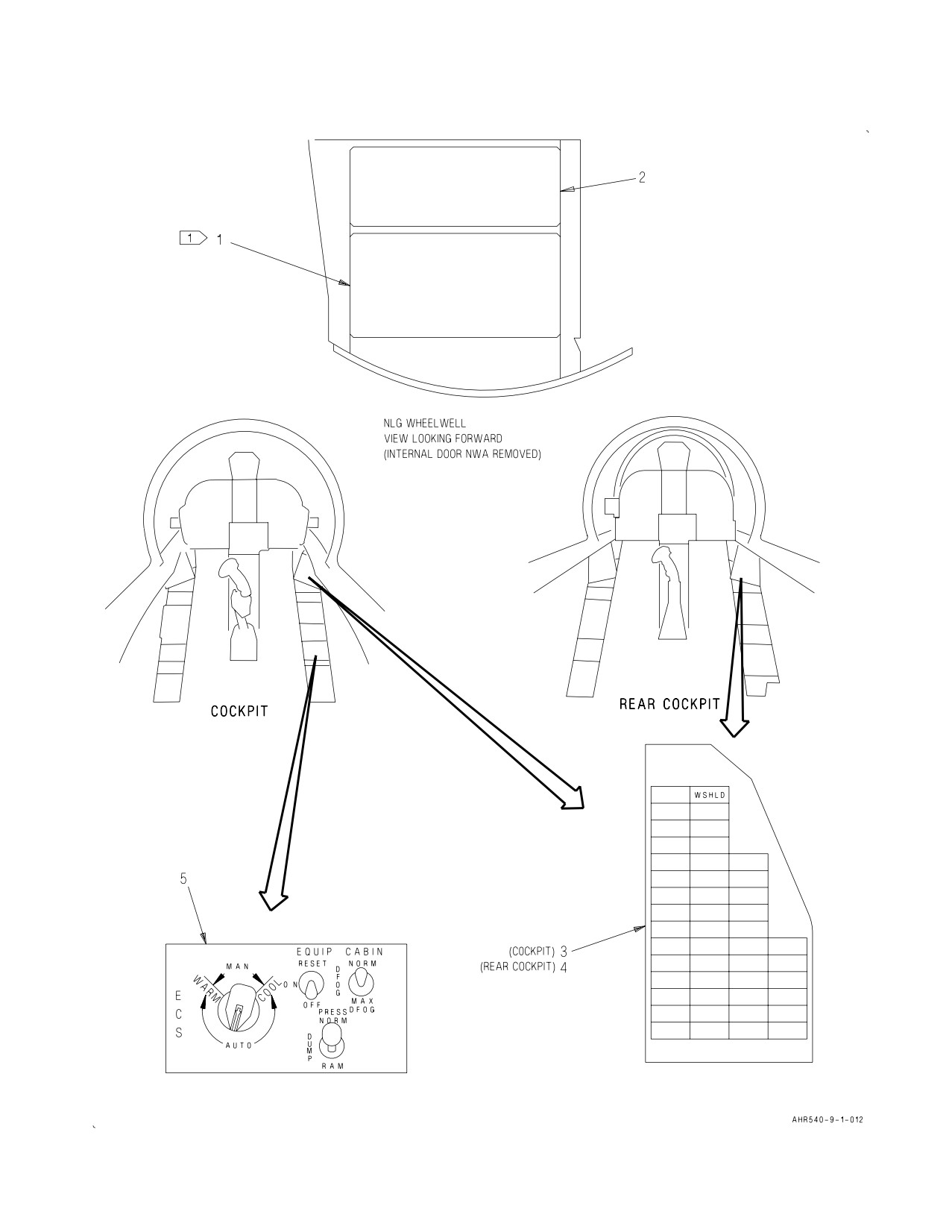
Rear WSHLD Caution Light
5
Windshield Overtemperature Relay
5
WSHLD Caution Light
5
System Description
3
Related Systems
4
DC Power System
4
Landing Gear and Related Systems
4
Power Plant and Related Systems
4
Warning/Caution/Advisory Lighting System
4
Operation
6
Component Operation
6
Cabin ECS Air Filter Assembly
6
Cabin ECS Check Valve
7
Cabin ECS Pressure Regulating and Shutoff Valve
6
Cabin Temperature Sensor
9
Cold Air Unit
7
Defog Shutoff Valve
8
Duct Temperature Sensor
9
ECS Control Panel Assembly
8
ECS Louvers
8
ECS Pressure Switch
8
Fixed Canopy Ventilation Nozzles
8
Forward Vent/Defog Valve
7
Primary Heat Exchanger
6
Rear Vent/Defog Valve
7
Secondary Heat Exchanger
7
Skin Temperature Sensor
8
Temperature Regulating Valve
6
Water Separator
7
Windshield Defog Nozzles
8
Windshield Overtemperature Switch
8
System Operation
9
Emergency Operation
10
Normal Operation
9
A1-AV8BC-410-100
004 00
Change 7
Page 3
Record of Applicable Technical Directives
Type/
Date
Date
Title and ECP or RAMEC No.
Remarks
Number
Incorp.
AV8AFC-416
— TAV-8B Polyimide Wire Replacement/
15 May 04
—
Power Wire Separation (ECP MDA-AV8B-
0277)
1. DESCRIPTION.
9. Water Separator. The water separator is a swirl
frame, a woven cloth coalescer, and a bypass valve
2. SYSTEM DESCRIPTION. The cabin cooling and
in a common housing.
defog system conditions hot sixth stage engine bleed
air to satisfy cockpit environmental requirements.
10. Forward Vent/Defog Valve. The vent/defog
valve is a solenoid controlled, pneumatically
3. COMPONENT DESCRIPTION. System
actuated, two position valve. The valve is made up
components are described and listed in the
of a housing, movable piston and a control solenoid.
paragraphs below. For component locator, refer to
WP005 00.
11. ECS Louvers. The ECS louvers are adjustable
metal air outlets.
4. Cabin ECS Air Filter Assembly. The cabin ECS
air filter assembly is a reusable, steel mesh filter
12. Windshield Defog Nozzles/Fixed Canopy
element encased in a housing with a spring loaded
Ventilation Nozzles. The windshield defog nozzles
bypass valve.
and fixed canopy ventilation nozzles are tapered,
slotted, metal tubes.
5. Cabin ECS Pressure Regulating and Shutoff
13. ECS Control Panel Assembly. The ECS control
Valve. The cabin ECS pressure regulating and
panel is a console mounted, illuminated control
shutoff valve is an electrically controlled,
panel which provides mounting for environmental
pneumatically operated valve. The valve is made up
control system controls.
of a solenoid controlled shutoff section and a
pneumatically controlled pressure regulating
14. Windshield Overtemperature Switch. The
section. The shutoff section is made up of a
windshield overtemperature switch is an in-line
solenoid operated control valve and a spring loaded
temperature sensitive, bimetallic, electrical switch.
shutoff piston mounted on a shaft. The pressure
regulating section is made up of two sensing
15. Skin Temperature Sensor. The skin
chambers, a relief valve, and a spring loaded piston
temperature sensor is a thermometer element
mounted on a shaft.
imbedded in a contact strip.
6. Venturi/Choke. The venturi/choke is a metal
16. Duct Temperature Sensor. The duct
duct assembly with a constricted throat.
temperature sensor is a thermistor enclosed in a
threaded housing.
7. Temperature Regulating Valve. The
temperature regulating valve is an electrically
17. Cabin Temperature Sensor. The cabin
driven butterfly type valve. The valve is made up of
temperature sensor is a thermistor enclosed in a
a butterfly valve, actuator, an integral follow-up
housing attached to a mount bracket.
resistor and a brake.
18. Cabin ECS Check Valve. The cabin ECS check
8. Cold Air Unit. The cold air unit is a compressor
valve is a flapper type, spring loaded closed check
turbine and expansion turbine, mounted at opposite
valve.
ends of a common shaft, in a common housing. The
cold air unit has a serviceable bearing lubrication
19. Defog Shutoff Valve. The defog shutoff valve is
system and a bearing cooling system.
an electrically controlled, pneumatically actuated
shutoff valve.
A1-AV8BC-410-100
004 00
Change 7
Page 4
20. ECS Pressure Switch. The ECS pressure switch
MLG weight on wheels (WOW) switch and the
is a pneumatically actuated electrical switch.
weight on wheels relay no. 1.
30. SYSTEM CONTROLS AND INDICATORS.
21. Rear Vent/Defog Valve. The rear vent/defog
valve is a solenoid controlled, pneumatically
31. CABIN Switch. The CABIN switch, located on
actuated, two position valve. The valve is made up
the ECS control panel assembly, is a single pole
of a housing, movable piston, and a control
toggle switch. The switch controls airflow for cabin
solenoid.
and windshield defogging. The switch has three
positions: NORM, DFOG, and MAX DFOG.
22. Primary Heat Exchanger. The primary heat
exchanger is a crossflow, air to air heat exchanger.
32. Setting the CABIN switch to NORM does the
The heat exchanger is made up of a finned core
below:
enclosed in a housing.
a. Applies essential 28vdc to energize the
23. Secondary Heat Exchanger. The secondary
forward vent/defog valve and rear vent/defog valve,
heat exchanger is a crossflow, air to air heat
causing them to go to the unrestricted position.
exchanger. The heat exchanger is made up of a
finned core enclosed in a housing.
b. Applies essential 28vdc through the weight
on wheels relay no. 1 to the defog shutoff valve. The
24. RELATED SYSTEMS.
defog valve will close if the aircraft is weight on
wheels and system pressure is less than 20 psi.
25. Power Plant and Related Systems. Hot, high
33. Setting the CABIN switch to DFOG does the
pressure bleed air is provided by the engine sixth
below:
stage compressor (A1-AV8BD-290-100, WP003 00).
a. Removes essential 28vdc to deenergize the
26. Warning/Caution/Advisory Lighting System.
forward vent/defog valve and rear vent/defog valve,
The warning/caution/advisory lighting system
causing them to go to the restricted position.
(A1-AV8BB-440-100, WP007 00) provides visual
indication of normal aircraft functions and system
b. Removes essential 28vdc to open the defog
malfunctions affecting safety of flight operations.
shutoff valve.
The warning/caution/advisory lighting system
34. Setting the CABIN switch to MAX DFOG
includes the annunciator light controller and the
applies essential 28vdc power to energize the max
caution/advisory indicator light assembly. The
defog relay causing an increase in system air
annunciator light controller receives data from
temperature.
various aircraft systems and provides logic to turn
on and off warning/caution/advisory lights.
35. PRESS Switch. The PRESS switch, located on
the ECS control panel assembly, is a four pole, lever
27. The annunciator light controller will turn on
lock toggle switch. The switch provides on/off
the WSHLD caution lights and the MASTER
control for the cabin cooling and defog system and
CAUTION lights when defog air temperature
mode selection for the cabin pressurization system.
exceeds 250°F.
Refer to WP006 00 for operation of the cabin
pressurization system. The switch has three
28. DC Power System. The DC power system on
positions; NORM, DUMP, and RAM.
162747; ALSO 162963 THRU 163861 BEFORE
AV8AFC-416 (A1-AV8BB-420-100, WP004 00) or
36. Setting the PRESS switch to NORM prevents
164113 AND UP; ALSO 162963 THRU 163861
28vdc essential or 28vdc emergency power from
AFTER AV8AFC-416 (A1-AV8BD-420-100, WP004
energizing the cabin ECS pressure regulating and
00) provides 28vdc essential and 28vdc emergency
shutoff valve, allowing normal system operation.
power for the cabin cooling and defog system.
37. Setting the PRESS switch to RAM applies
29. Landing Gear And Related Systems. The
28vdc essential and 28vdc emergency power to
landing gear system (A1-AV8BB-130-100,
energize the cabin ECS pressure regulating and
WP003 00) provides a weight on wheels signal for
shutoff valve. The valve closes when energized,
the cabin cooling and defog system through the
stopping system operation.
A1-AV8BC-410-100
004 00
Page 5
38. Setting the PRESS switch to DUMP has no
44. WSHLD Caution Light. The WSHLD caution
affect on system operation.
light, located on the caution/advisory indicator light
assembly, is a dual lamp, indicator light.
39. Cabin Temperature Control. The cabin
temperature control, located on the ECS control
45. The WSHLD caution light is controlled by the
panel assembly, controls manual (MAN) and
windshield overtemperature switch through the
automatic (AUTO) cabin temperature selection.
windshield overtemp relay and the
warning/caution/advisory lighting system.
40. In the MAN mode, setting and holding the
46. Rear WSHLD Caution Light. The rear WSHLD
cabin temperature control knob to the COOL or
caution light, located on the rear caution/advisory
WARM settings applies emergency 28vdc power
indicator light assembly, is a dual lamp indicator
through the deenergized windshield overtemp relay
light.
to the open (warm) or closed (cool) contacts of the
temperature regulating valve. Voltage is applied to
47. The rear WSHLD caution light is functionally
the valve as long as the knob is held in COOL or
identical to the WSHLD caution light.
WARM setting.
48. Windshield Overtemperature Relay. The
41. In the AUTO mode, the cabin temperature
windshield overtemperature relay, located on the
control functions as an electronic processor and as
forward relay no. 1 panel assembly, is a dual pole,
one leg of a temperature control bridge circuit. The
double throw, 5 amperes, permanent magnet drive,
other legs of the bridge circuit include the cabin
armature relay.
temperature sensor, duct temperature sensor, and
skin temperature sensor and follow-up resistor.
49. The relay is energized when the windshield
overtemperature switch senses defog air
42. Selecting the desired setting in the AUTO mode
temperature is more than 250° ±8°F. With the relay
applies emergency 28vdc power to the processing
energized:
electronics and to the normally open contacts of the
a. Emergency 28vdc is removed from the cabin
heat and cool relays, and provides a resistance value
temperature control and is applied directly to the
for one leg of the bridge. The cabin temperature
close (cool) contacts of the temperature regulating
control continuously receives signals from all legs of
valve, causing a decrease in system temperature.
the bridge circuit. The bridge circuit compares the
selected resistance of the AUTO setting with the
b. A ground is removed to enable the WSHLD
sensed resistance of the other bridge circuit legs.
caution light and the rear WSHLD caution light.
Any difference in the signals is an unbalance. The
unbalance is electronically processed and used to
50. With the relay deenergized:
energize either the heat or cool relay. Energizing the
relays applies emergency 28vdc power to the open
a. Emergency 28vdc is applied to the cabin
(warm) or closed (cool) contacts of the temperature
temperature control allowing removal system
regulating valve. The valve moves as required,
operation.
adding or removing hot air. Out of balance signals
are proportional to sensed temperature changes.
b. A ground is provided to disable the WSHLD
The resistance of the sensors and follow-up resistor
caution light and rear WSHLD caution light.
changes as the valve opens and closes until a
balance in the bridge circuit is arrived at.
51. Max Defog Relay. The max defog relay, located
on the forward relay no. 1 panel assembly, is a dual
43. An unbalance will occur by changing the
pole, double throw, 5 amperes, permanent magnet
selected temperature or by any change in
drive, armature relay.
temperature as sensed by any leg of the bridge.
Such changes may be a drastic change in ambient
52. The relay is energized when the CABIN switch
temperature because of increased or decreased
is set to MAX DFOG. The relay allows windshield
altitude. The cabin temperature control will
defogging air temperature to increase in the MAX
automatically compensate for these changes to
DFOG setting. With the relay energized, signals
maintain the selected temperature.
from the cabin temperature sensor and duct
A1-AV8BC-410-100
004 00
Page 6
temperature sensor are routed through three fixed
chamber is held constant by the relief valve.
valve resistors. The three resistors increase the total
Differences of pressure between the two chambers
signal resistance, causing an imbalance in the
determines piston position, controlling air pressure
temperature control bridge circuit. The cabin
passing into the system. Pressure is regulated to
temperature control will increase air temperature
approximately 62 psi.
until the bridge circuit is brought back into balance.
60. Temperature Regulating Valve. The
53. With the relay deenergized, cabin temperature
temperature regulating valve is located in door 128
sensor and duct temperature sensor signals are
between the cabin pressure regulator and shutoff
routed directly through the cabin temperature
valve and the water separator. The valve is
control bridge circuit.
electrically controlled and electrically actuated.
54. OPERATION.
61. Acting in response to electrical signals from the
cabin temperature control, the valve moves open or
55. COMPONENT OPERATION.
closed. Opening the valve allows more hot air to mix
with cold discharge air from the cold air unit.
56. Cabin ECS Air Filter Assembly. The cabin
Closing the valve allows less hot air mixing. Cycle
ECS air filter assembly is located in door 11L. Sixth
time of the valve from fully open to fully closed is
stage engine bleed air is sent by way of ducting to
approximately 15 seconds.
the filter assembly. The filter assembly removes
particulate contamination before it can cause
The valve motor has limit switches and a brake to
damage further downstream in the environmental
prevent overtravel of the valve. The closed limit
control systems. If the filter element becomes
switch is open when the valve is closed. The limit
blocked, pressure build up opens a bypass valve
switch opens the circuit for the valve and
allowing air to bypass the filter element. The bypass
deenergizes the brake coil. Power to the motor is
valve opens at 4 psid. The filter element is
interrupted and the brake engages. As the valve
replaceable independent of the housing or may be
opens, the closed limit switch closes. When the
cleaned and reused. With the filter element
valve is fully open, the process repeats for the open
removed, a ground air source can be adapted and
limit switch.
used for ground testing.
62. The follow-up resistor is a variable resistor
57. Cabin ECS Pressure Regulating and Shutoff
mechanically controlled by position of the valve
Valve. The cabin pressure regulating and shutoff
actuator. Resistance values increase as the valve
valve is located in the bleed air duct between the
moves to open, decrease as the valve moves to
cabin ECS air filter assembly and primary heat
closed. The resistance value range is approximately
exchanger in door 128. Operation of the pressure
0 to 33 ohms. The resistance value is supplied to
regulating section and shutoff section is separate.
the automatic mode of the cabin temperature
Both sections require engine bleed air for operation.
control as part of one leg of the bridge circuit.
58. The shutoff section is controlled by the PRESS
63. Primary Heat Exchanger. The primary heat
switch on the ECS control panel assembly. With the
exchanger is located in door 128 between the cabin
solenoid deenergized, bleed air is applied to the
ECS pressure regulating and shutoff valve and the
upstream side of the shutoff piston, moving it to the
cold air unit. Hot bleed air passes through the heat
open position. With the solenoid energized the
exchanger core where ram air, forced across the
control valve opens equalizing bleed air pressure on
core, absorbs heat from the bleed air. The bleed air
both sides of the shutoff piston which closes by
passes through the heat exchanger then to the cold
spring tension. In the event of an aircraft or valve
air unit compressor turbine. The pre-cooled,
electrical failure, the valve will fail to the open
compressed bleed air is then sent to the secondary
position. The shutoff section will be inoperative, but
heat exchanger.
the pressure regulation section will continue to
operate.
64. After passing across the primary heat
exchanger, the ram air exits through either the ECS
59. The pressure regulating section operates only
bay or the engine intake, depending on flight
with the shutoff section open. Bleed air pressure
conditions. In low speed flight or ground operation,
enters both sensing chambers. Pressure in one
flapper valves at the bottom of the heat exchanger
A1-AV8BC-410-100
004 00
Page 7
are pulled open by suction in the engine air intake,
by centrifugal force. The droplets are collected by
allowing engine intake suction to pull ram air across
the sump assembly and allowed to drain overboard.
the heat exchanger core. In normal flight, ram air
flow causes a positive pressure in the ram air ducts,
71. If the coalescer becomes blocked, normally
pulling the flapper valves closed. The ram air then
because of freezing, a bypass valve will open at a 10
exits to the ECS bay and then overboard.
psi differential pressure.
65. Secondary Heat Exchanger. The secondary
72. Cabin ECS Check Valve. The cabin ECS check
heat exchanger is located in door 128 between the
valve is located between the water separator and
cold air unit compressor turbine outlet and
the duct temperature sensor in internal door NWA.
expansion turbine inlet. Pre-cooled, compressed
The valve prevents cabin depressurization by
bleed air from the cold air unit compressor turbine
stopping the reverse flow of cabin air, through ECS
passes through the heat exchanger core where ram
louvers, windshield defog nozzles, and fixed canopy
air, forced across the core, absorbs heat gained
ventilation nozzles when cabin cooling and defog
through compression. The cooled air then passes to
system is not operating. The valve flappers are held
the expansion turbine inlet of the cold air unit.
closed by spring tension and are normally closed
with no air pressure applied. Approximately 4 psi is
66. The exit path of the ram air is the same as the
required to open the check valve.
primary heat exchanger.
73. Forward Vent/Defog Valve. The forward
67. Cold Air Unit. The cold air unit is located in
vent/defog valve, located between the water
door 128 between the heat exchangers and the
separator and the cockpit ECS louvers in door 10,
water separator. The compressor turbine receives
provides restricted or unrestricted flow. The valve
pre-cooled air from the primary heat exchanger
solenoid is energized when the CABIN switch is set
where it is compressed to approximately two times
to NORM and deenergized when the CABIN switch
its inlet value. The compressed air then passes to
is set to DFOG or MAX DFOG. With the solenoid
the secondary heat exchanger where the heat from
energized, pneumatic pressure is turned off,
compression is lost, then to the expansion turbine
allowing system pressure to force the movable
end of the cold air unit where heat energy is
piston to the unrestricted position. With the valve
converted to mechanical energy by spinning the
in the unrestricted position, most of the airflow will
expansion turbine. The expansion turbine drives the
be directed to the cockpit ECS louvers.
compressor turbine through the common shaft.
With the heat lost, cold air is left and sent by way
74. Deenergizing the solenoid applies pneumatic
of ducting to mix with hot air from the temperature
pressure to the movable piston, causing it to move
regulating valve.
to the restricted position; most of the airflow will
then be directed to the windshield defog nozzles
68. Lubrication for the common shaft is provided
and the fixed canopy ventilation nozzles.
by oil stored in a cotton wool pack sump and
transported to the shaft by a system of oil wicks.
75. Rear Vent/Defog Valve. The rear vent/defog
The sump has fill and drain plugs located to allow
valve, located between the duct temperature sensor
periodic servicing of oil while the cold air unit is
and the rear cockpit ECS louvers in door 121,
still in the aircraft.
provides restricted or unrestricted flow. The valve
69. Shaft bearing cooling is provided by a flexible
solenoid is energized when the CABIN switch is set
tube. Expansion turbine discharge air is used to
to NORM and deenergized with the CABIN switch
cool the bearings as the common shaft spins.
set to DFOG or MAX DFOG. With the solenoid
energized, pneumatic pressure is turned off allowing
70. Water Separator. The water separator is
system pressure to force the movable piston to the
located between the cold air unit and the cabin ECS
unrestricted position. With the valve in the
check valve in internal door NWA. Cool moist air
unrestricted position, most of the airflow will be
enters the water separator coalescer. The coalescer
directed to the rear cockpit ECS louvers.
converts moisture in the air into water droplets
through the wettable, high surface area of the
76. Deenergizing the solenoid applies pneumatic
woven cloth coalescer. The swirl frame sends these
pressure to the movable piston, causing it to move
droplets to the outer wall of the collector sump area
to the restricted position; most of the airflow will
A1-AV8BC-410-100
004 00
Page 8
then be directed to the fixed canopy ventilation
shut off. Spring tension overcomes pneumatic
nozzles and windshield defog nozzles.
pressure to open the valve.
77. ECS Louvers. The ECS louvers, located in the
82. ECS Pressure Switch. The ECS pressure switch
cockpit and rear cockpit, provide desired
is located in door 128 in the primary heat exchanger
distribution of air entering the cockpits. Each of the
outlet. The switch is pneumatically operated and
louvers has adjustable vanes at the openings. The
controls electrical signals to the defog shutoff valve.
vanes can be adjusted by the pilot for his own
heating and cooling comfort. Airflow to the ECS
83. With system pressure less than 20 psi, a ground
louvers is controlled by the forward vent/defog
is supplied to energize the defog shutoff valve. With
valve and the rear vent/defog valve. The louvers
system pressure greater than 20 psi, the pneumatic
also act as an air inlet for cabin pressurization
switch opens to remove the ground signal, to
(WP006 00).
deenergize the defog shutoff valve.
78. Windshield Defog Nozzles. The windshield
84. ECS Control Panel Assembly. The ECS control
defog nozzles, at the base of the windshield, provide
panel assembly is located in the cockpit on the right
even flow of air across the windshield and canopy.
console. The panel provides mounting for the
Cabin air is used for windshield and canopy
PRESS switch, CABIN switch, cabin temperature
defogging. Air flow to the nozzles is controlled by
control, and EQUIP switch (WP008 00).
the forward vent/defog valve, rear vent/defog valve,
and defog shutoff valve. The nozzles also act as an
85. Windshield Overtemperature Switch. The
air inlet for cabin pressurization (WP006 00).
windshield overtemperature switch is located in
door 120 in the defog shutoff valve outlet duct. A
79. Fixed Canopy Ventilation Nozzles. The fixed
bimetallic temperature sensitive device senses an
canopy ventilation nozzles at the base of the fixed
overtemperature condition. The bimetallic
canopy provide an even flow of air across the fixed
properties allow the device to expand and contract
canopy. Cabin air is used for fixed canopy
to actuate the switch.
defogging. The nozzles also provide thorough
86. The switch is calibrated to close its contacts at
ventilation in and around the rear cockpit. Airflow
250 ±8°F increasing temperature and open at 220
to the nozzles is controlled by the forward
±10°F decreasing temperature.
vent/defog valve, rear vent/defog valve and defog
shutoff valve. The nozzles also act as an air inlet for
87. Closing the switch contacts provides a ground to
cabin pressurization (WP006 00).
complete a circuit which applies emergency 28vdc
power to energize the windshield overtemperature
80. Defog Shutoff Valve. The defog shutoff valve is
relay.
located in the common windshield defog and fixed
canopy ventilation duct in door 121. The valve
88. Skin Temperature Sensor. The skin
controls the flow of air to the windshield defog
temperature sensor is located on the left side nose
nozzles and fixed canopy ventilation nozzles when
landing gear wheelwell. The sensor senses changes
the aircraft is on the ground and system pressure is
in aircraft skin temperature. The sensing device
low. The valve is electrically controlled and
contact strip is attached directly to the aircraft
pneumatically actuated. The valve is controlled by
skin. A dielectric compound is used between the
the weight on wheels relay no. 1 and the ECS
sensor and the aircraft skin to make sure the sensor
pressure switch.
is electrically isolated from the skin, but still able to
measure temperature.
81. With aircraft weight on wheels and system
pressure less than 20 psi, the defog shutoff valve is
89. As sensed temperature increases, sensor
closed. The valve is energized and pneumatic
resistance increases. As sensed temperature
pressure is allowed to pass. The pressure, acting on
decreases, sensor resistance decreases. At a
a diaphragm, overcomes spring tension to close the
temperature range of 0 to 100°F (−17 to 40°C),
valve butterfly by way of a mechanical linkage.
sensor resistance is approximately 38 to 57 ohms.
With aircraft weight off wheels or system pressure
The resistance values are supplied to the automatic
greater than 20 psi, the defog shutoff valve is open.
mode of the cabin temperature control as part of
The valve is deenergized and pneumatic pressure is
one leg of the bridge circuit.
A1-AV8BC-410-100
004 00
Page 9
90. Duct Temperature Sensor. The duct
97. Distribution of air in the cockpits is determined
temperature sensor is located in a duct between the
by the forward vent/defog valve and the rear
water separator and the vent/defog valves in door
vent/defog valve through the ECS louvers. With
121. The sensor senses changes of air temperature
CABIN switch set to NORM, most of the airflow
in the cabin ECS duct.
will pass unrestricted to the ECS louvers. With the
CABIN switch set to DFOG or MAX DFOG, most
91. As sensed temperature increases, sensor
of the airflow will be directed to the windshield
resistance decreases. As sensed temperature
defog nozzles and fixed canopy ventilation nozzles.
decreases, sensor resistance increases. At a
temperature range of 32 to 100°F (0 to 40°C),
98. With weight on wheels and system pressure less
sensor resistance is approximately 1075 to 4850
than 20 psi, the defog shutoff valve is closed to
ohms. The resistance values are supplied to the
direct all airflow to the crewmembers through the
automatic mode of the cabin temperature control as
ECS louvers. With weight off wheels and system
one leg of the bridge circuit.
pressure greater than 20 psi, the defog shutoff valve
opens to allow a more balanced airflow between
92. Cabin Temperature Sensor. The cabin
nozzles and louvers.
temperature sensor is located on the forward
pressure bulkhead, in door 7L. The sensor senses
99. Cabin temperature can be controlled
changes in cabin air temperature.
automatically or manually. In automatic operation,
the cabin temperature control working with the
93. As sensed temperature increases, sensor
cabin temperature sensor, duct temperature sensor,
resistance decreases. As sensed temperature
and skin temperature sensor and follow-up resistor
decreases, sensor resistance increases. At a
automatically adjust temperature regulating valve
temperature range of 32 to 100°F (0 to 40°C),
position to control the temperature of air entering
sensor resistance is approximately 1075 to 5000
the cabin.
ohms. The resistance values are supplied to the
automatic mode of the cabin temperature control as
100. With the cabin temperature control set to
one leg of the bridge circuit.
MAN WARM or MAN COOL, 28vdc is applied to
the temperature regulating valve to control the
94. SYSTEM OPERATION.
temperature of the air entering the cabin.
95. Normal Operation. In normal operation, hot
101. Air for canopy and windshield defogging and
engine bleed air passes through the cabin ECS air
fixed canopy ventilation is provided through the
filter (figure 1) to the cabin ECS pressure regulating
windshield defog nozzles and fixed canopy
and shutoff valve which regulates pressure to
ventilation nozzles. Setting the CABIN switch to
approximately 62 psi. The regulated air passes
DFOG will direct most of the airflow to the
through the venturi/choke where airflow is limited
windshield defog nozzles. With CABIN switch set to
to approximately 36 pounds per minute. Regulated
MAX DFOG, the max defog relay is energized,
air then passes into two circuits, one remains hot,
causing the temperature of the airflow to increase.
the other passes to the primary heat exchanger to
The windshield overtemperature switch limits
be cooled. Hot air entering the primary heat
windshield defog air temperature to approximately
exchanger is cooled by cross flowing ram air. Partly
250°F. If an overtemperature condition exists, the
cooled air is then transported by way of ducting to
switch provides a ground to energize the windshield
the compressor turbine of the cold air unit where it
overtemperature relay. With the relay energized, the
is compressed to approximately two times its inlet
temperature regulating valve will close and the
value. Heat gained from the cold air unit
WSHLD caution lights are enabled.
compressor turbine is lost in the secondary heat
exchanger. Air from the secondary heat exchanger is
cooled further by rapid expansion in the cold air
unit expansion turbine section.
96. The temperature regulating valve controls the
amount of hot bleed air to be mixed with cold air
unit discharge air. Hot and cold air are mixed to the
required temperature.
A1-AV8BC-410-100
004 00
Page 10
102. EMERGENCY OPERATION. If the cabin
the ground cooling valve is shut off, causing the
cooling and defog system fails or is off, ram air can
valve to open (WP008 00). With the ground cooling
be used to ventilate the cockpit. Setting the PRESS
valve open, ram air can enter the cockpits through
switch to RAM closes the cabin ECS pressure
the ECS louvers, windshield defog nozzles and fixed
regulating and shutoff valve. Control air pressure to
canopy ventilation nozzles.
A1-AV8BC-410-100
004 00
Page 11
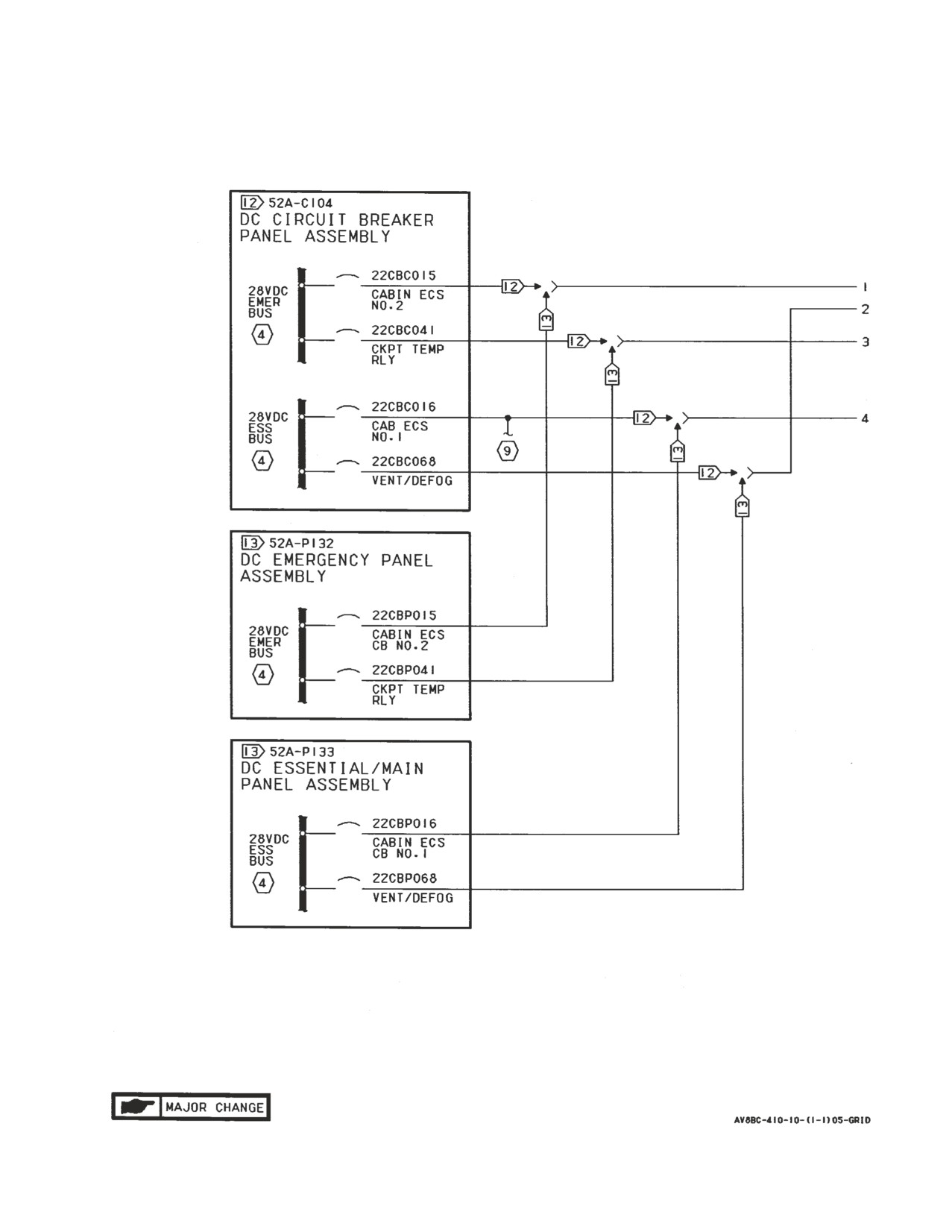
Figure 1. Cabin Cooling and Defog System Simplified Schematic (Sheet 1)
A1-AV8BC-410-100
004 00
Page 12
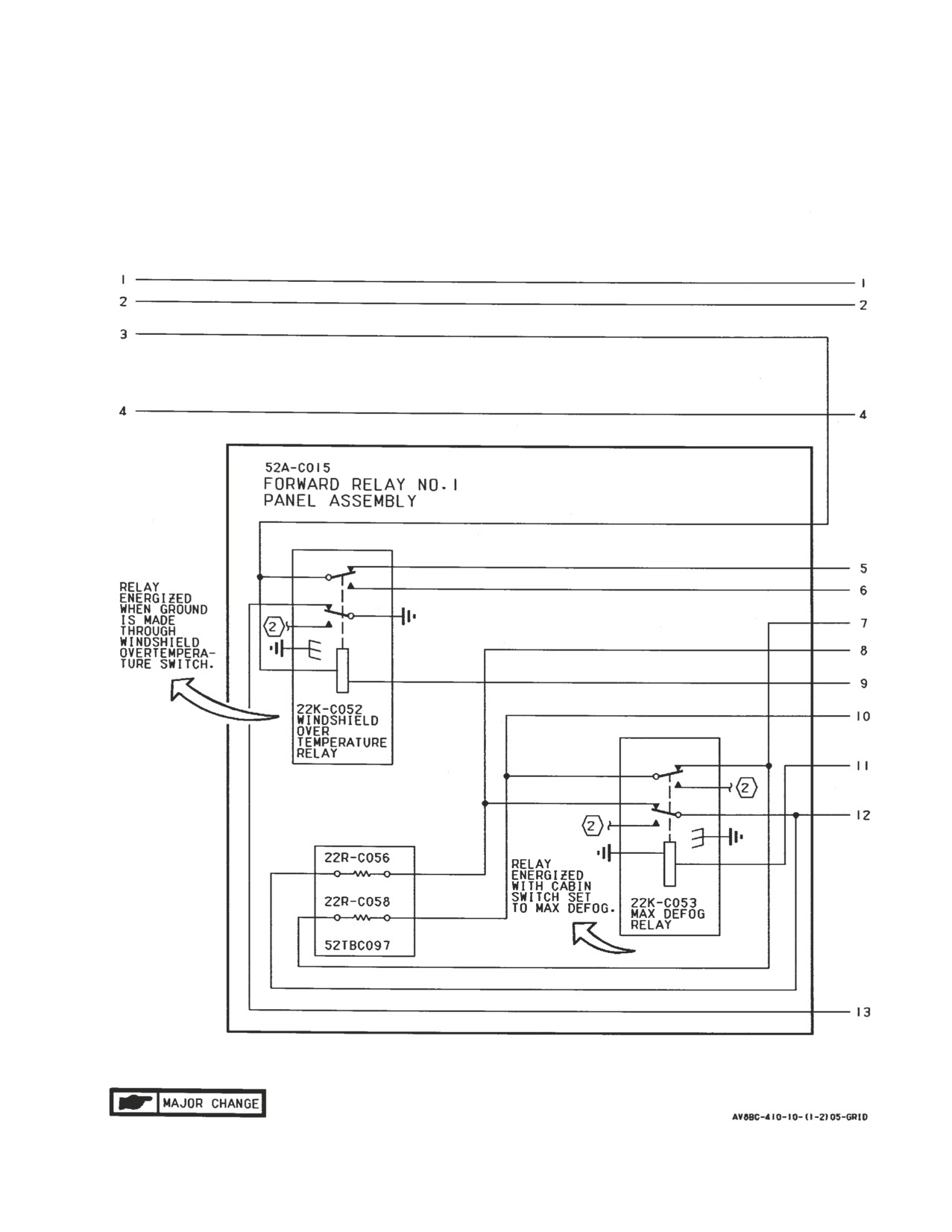
Figure 1. Cabin Cooling and Defog System Simplified Schematic (Sheet 2)
A1-AV8BC-410-100
004 00
Page 13
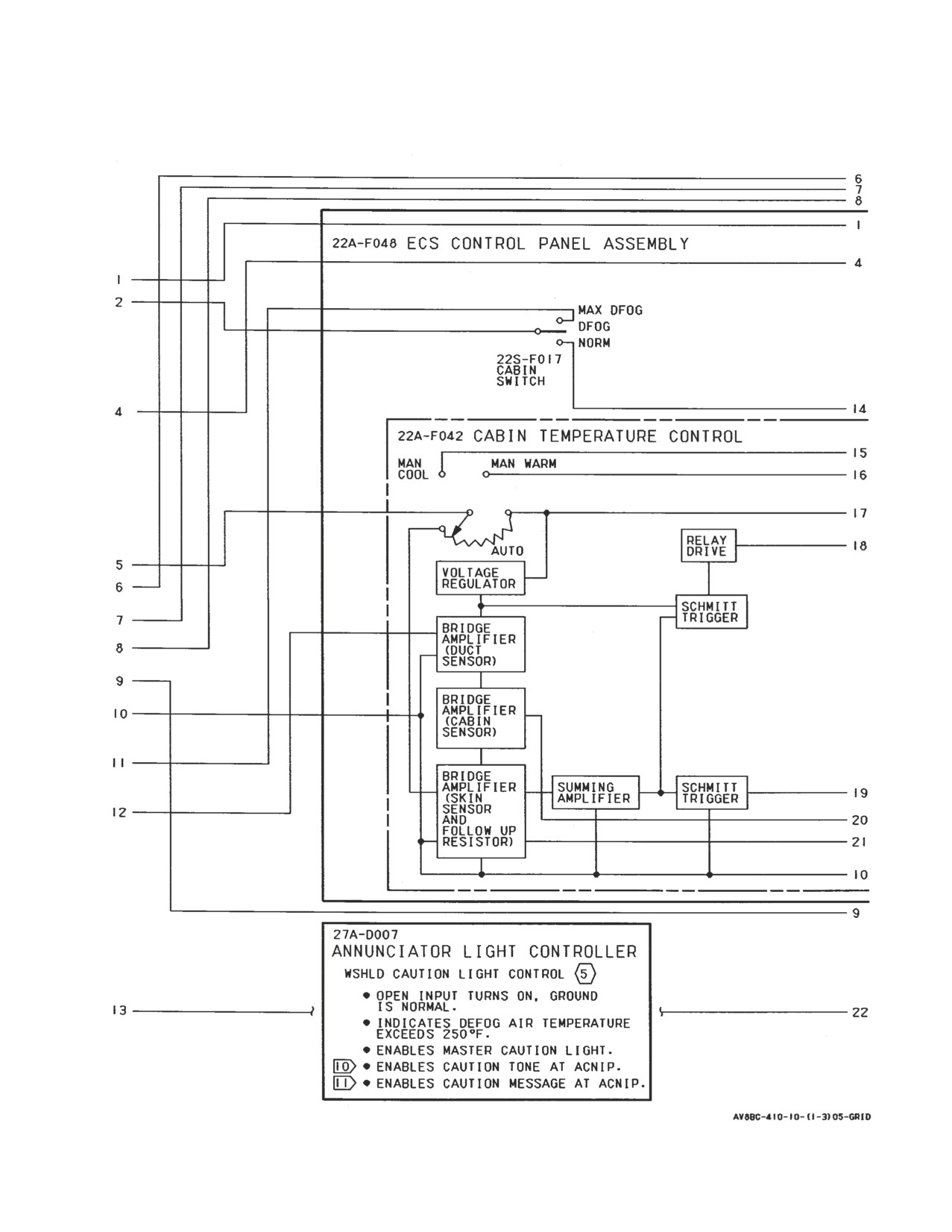
Figure 1. Cabin Cooling and Defog System Simplified Schematic (Sheet 3)
A1-AV8BC-410-100
004 00
Page 14
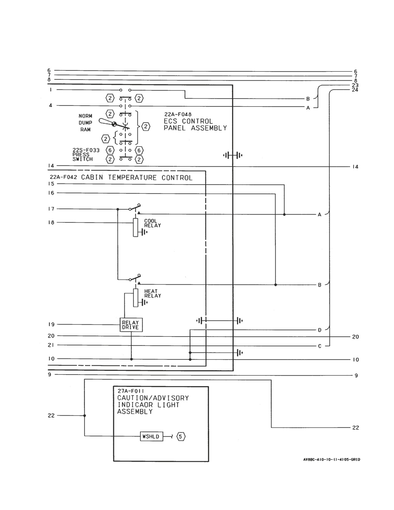
Figure 1. Cabin Cooling and Defog System Simplified Schematic (Sheet 4)
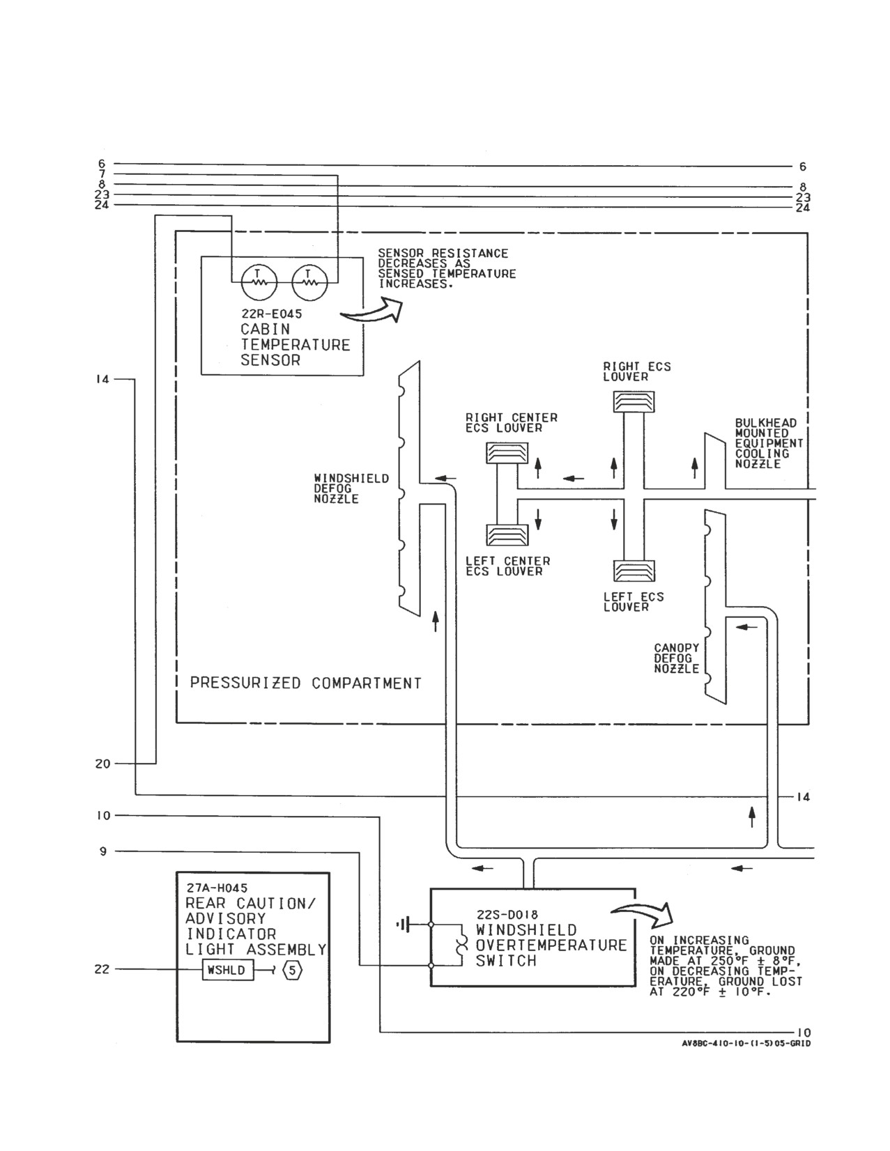
A1-AV8BC-410-100
004 00
Page 15
Figure 1. Cabin Cooling and Defog System Simplified Schematic (Sheet 5)
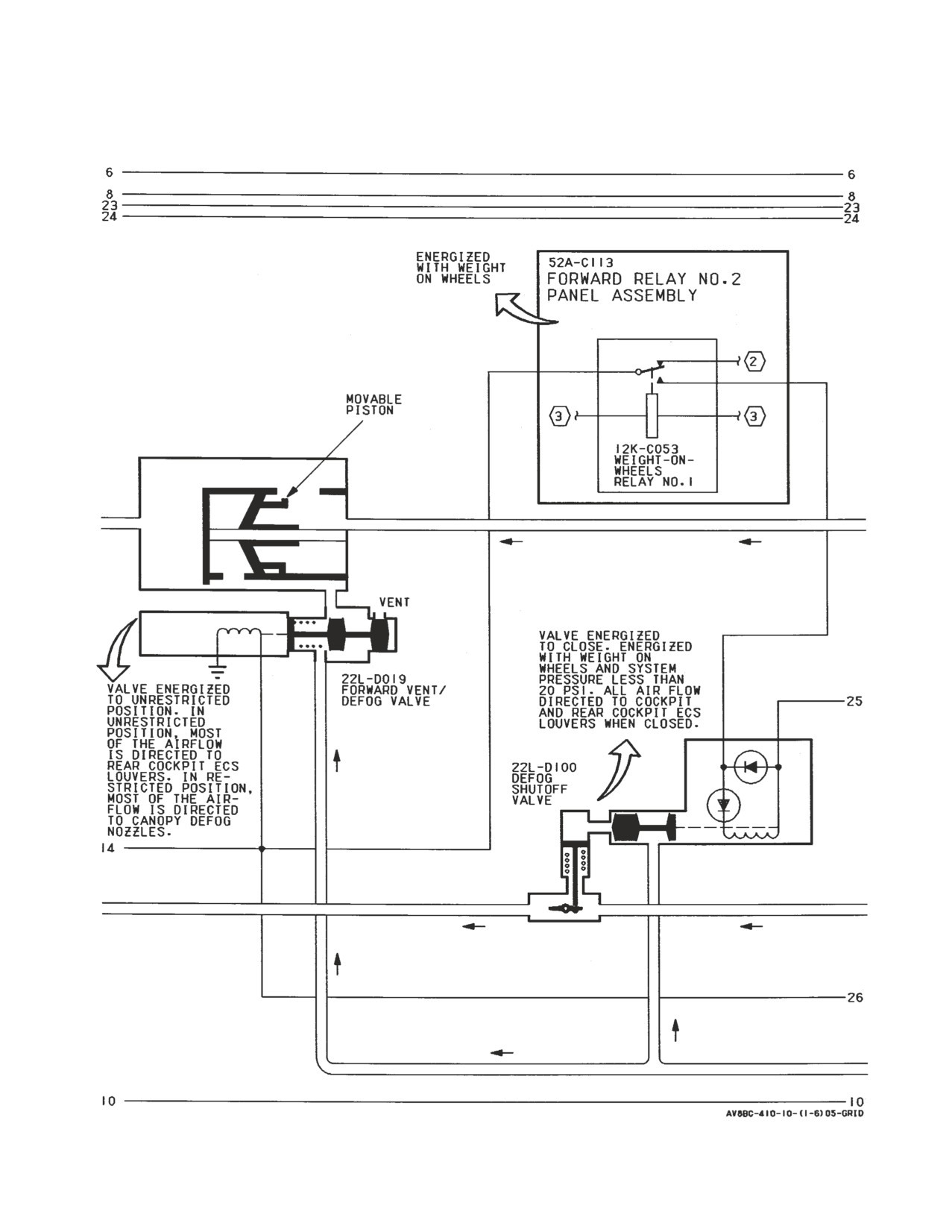
A1-AV8BC-410-100
004 00
Page 16
Figure 1. Cabin Cooling and Defog System Simplified Schematic (Sheet 6)
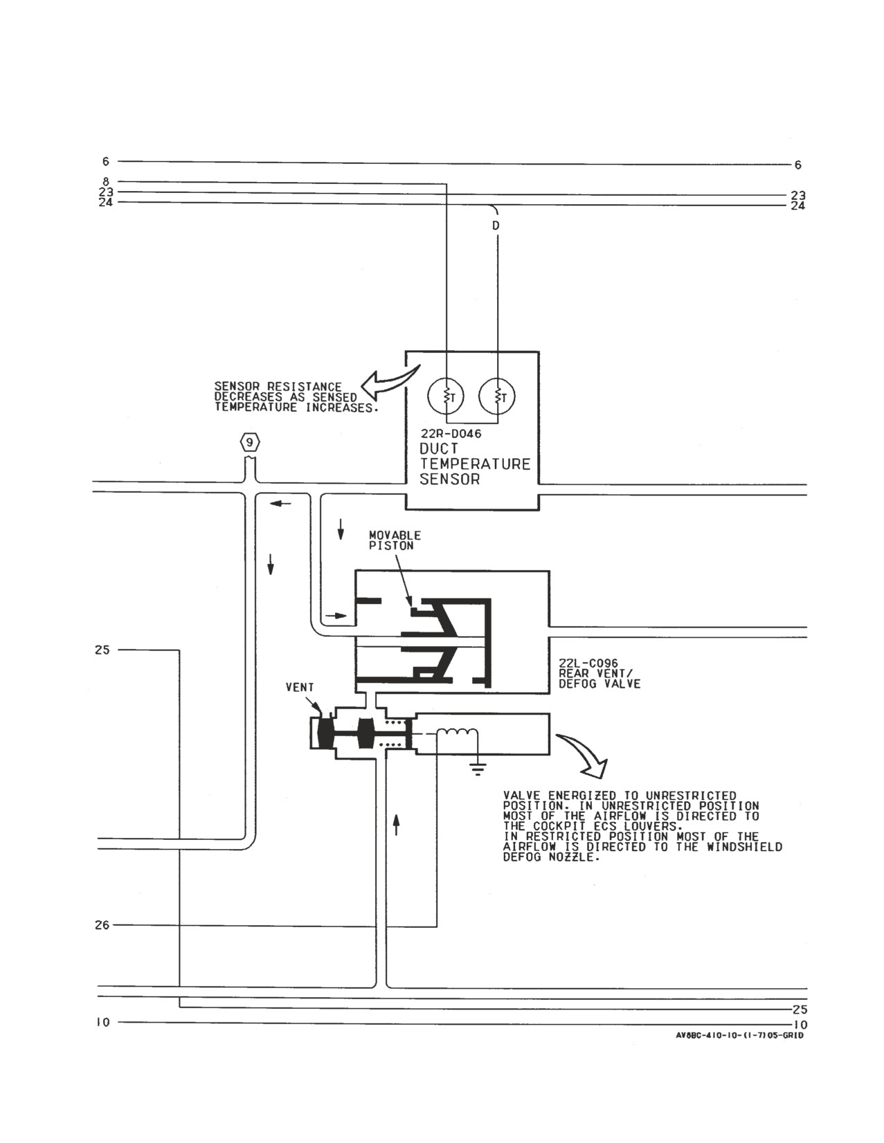
A1-AV8BC-410-100
004 00
Page 17
Figure 1. Cabin Cooling and Defog System Simplified Schematic (Sheet 7)
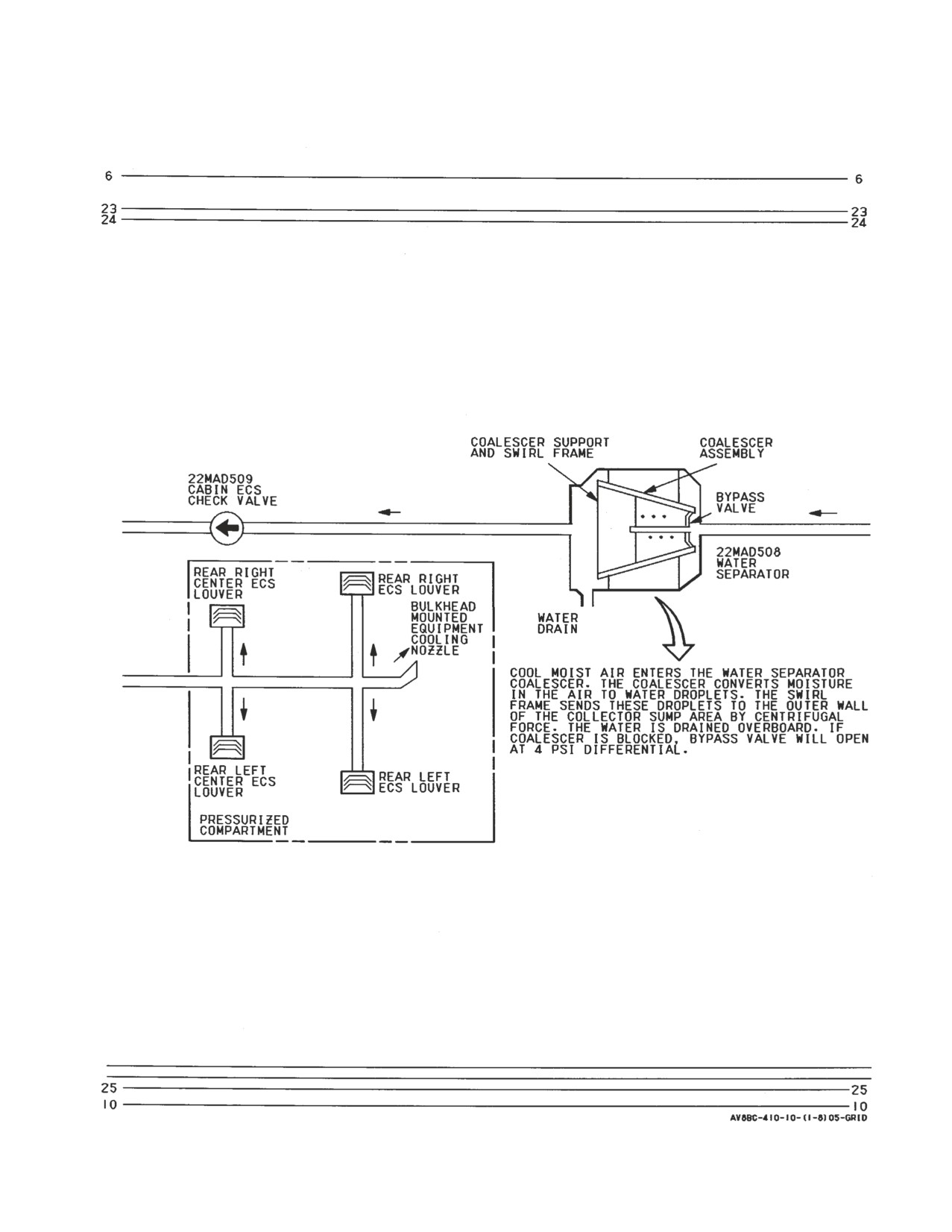
A1-AV8BC-410-100
004 00
Page 18
Figure 1. Cabin Cooling and Defog System Simplified Schematic (Sheet 8)
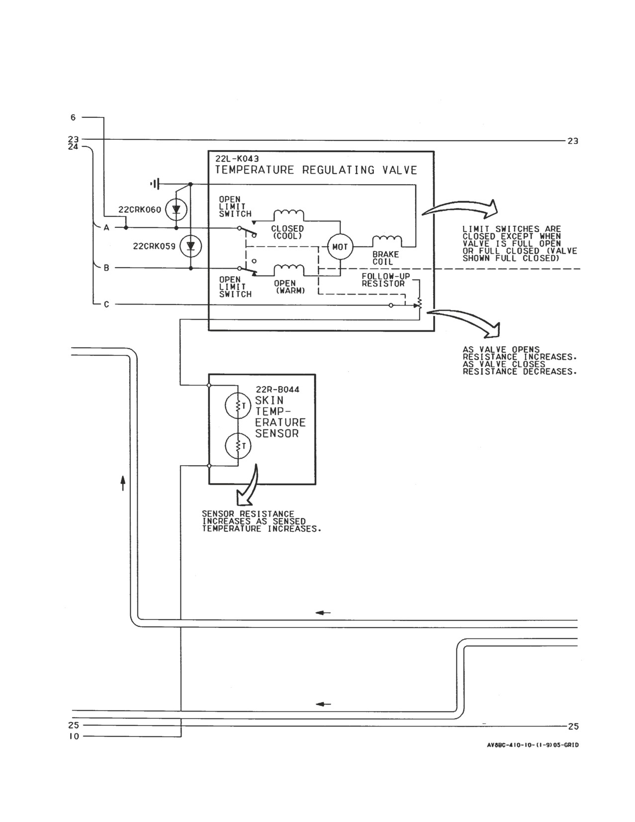
A1-AV8BC-410-100
004 00
Page 19
Figure 1. Cabin Cooling and Defog System Simplified Schematic (Sheet 9)
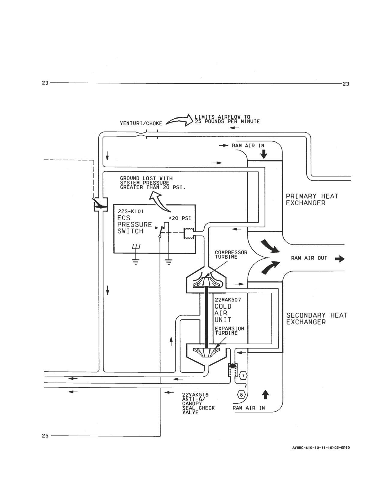
A1-AV8BC-410-100
004 00
Page 20
Figure 1. Cabin Cooling and Defog System Simplified Schematic (Sheet 10)
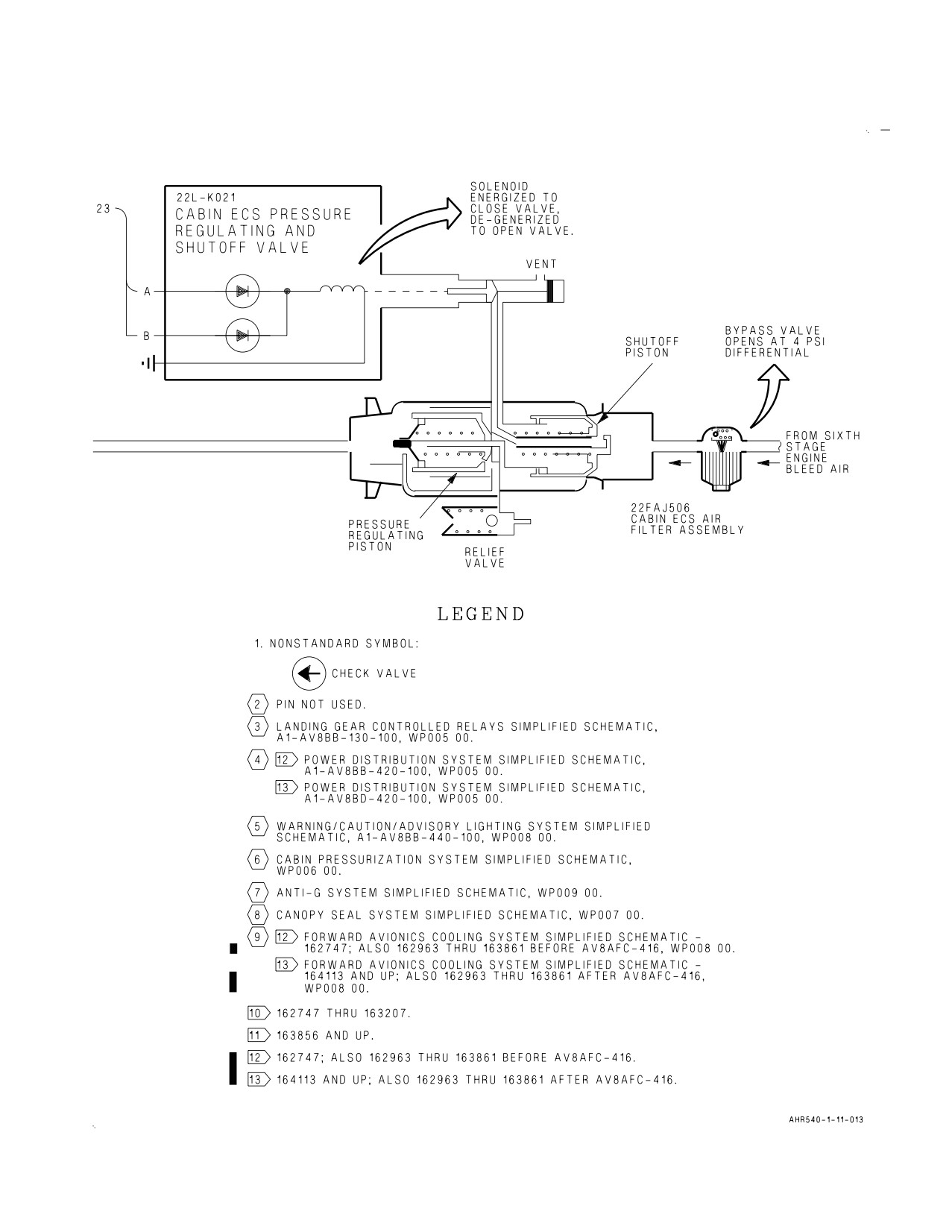
A1-AV8BC-410-100
004 00
Change 7
Page 21/(22 blank)
Figure 1. Cabin Cooling and Defog System Simplified Schematic (Sheet 11)

A1-AV8BC-410-100
005 00
Change 7 - 15 May 2004
Page 1
ORGANIZATIONAL MAINTENANCE
PRINCIPLES OF OPERATION
COMPONENT LOCATOR
CABIN COOLING AND DEFOG SYSTEM
This WP supersedes WP005 00, dated 15 June 2003.
Reference Material
None
Alphabetical Index
Subject
Page No.
Cabin Cooling and Defog System Component Locator, Figure 1
2
Record of Applicable Technical Directives
Type/
Date
Date
Title and ECP or RAMEC No.
Remarks
Number
Incorp.
AV8AFC-416
— TAV-8B Polyimide Wire Replacement/
15 May 04
—
Power Wire Separation (ECP MDA-AV8B-
0277)
A1-AV8BC-410-100
005 00
Change 7
Page 2
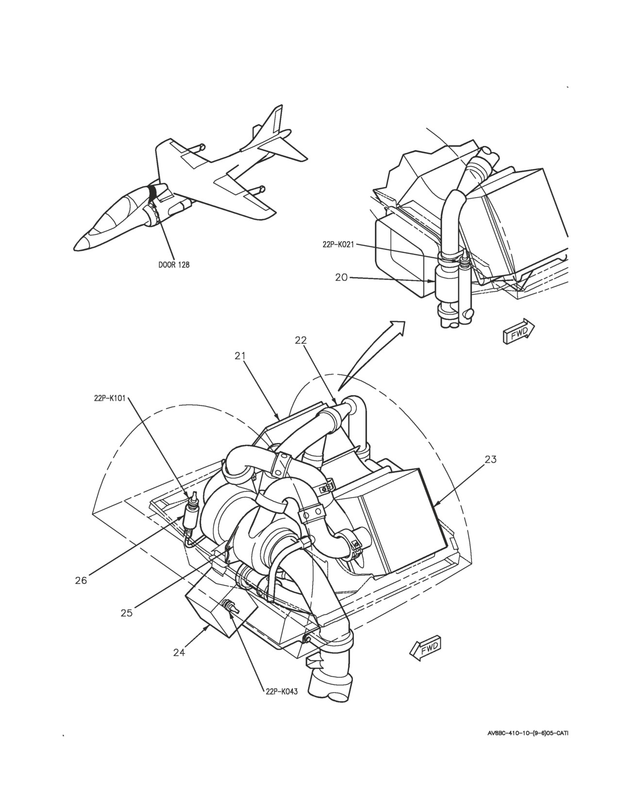
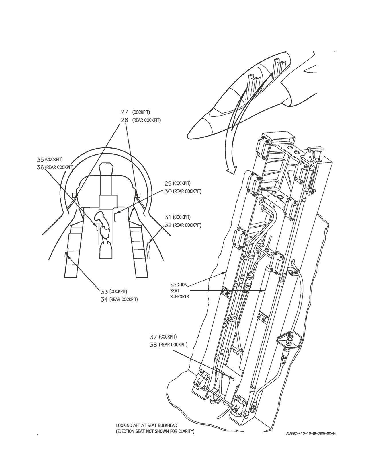
Figure 1. Cabin Cooling and Defog System Component Locator (Sheet 1)
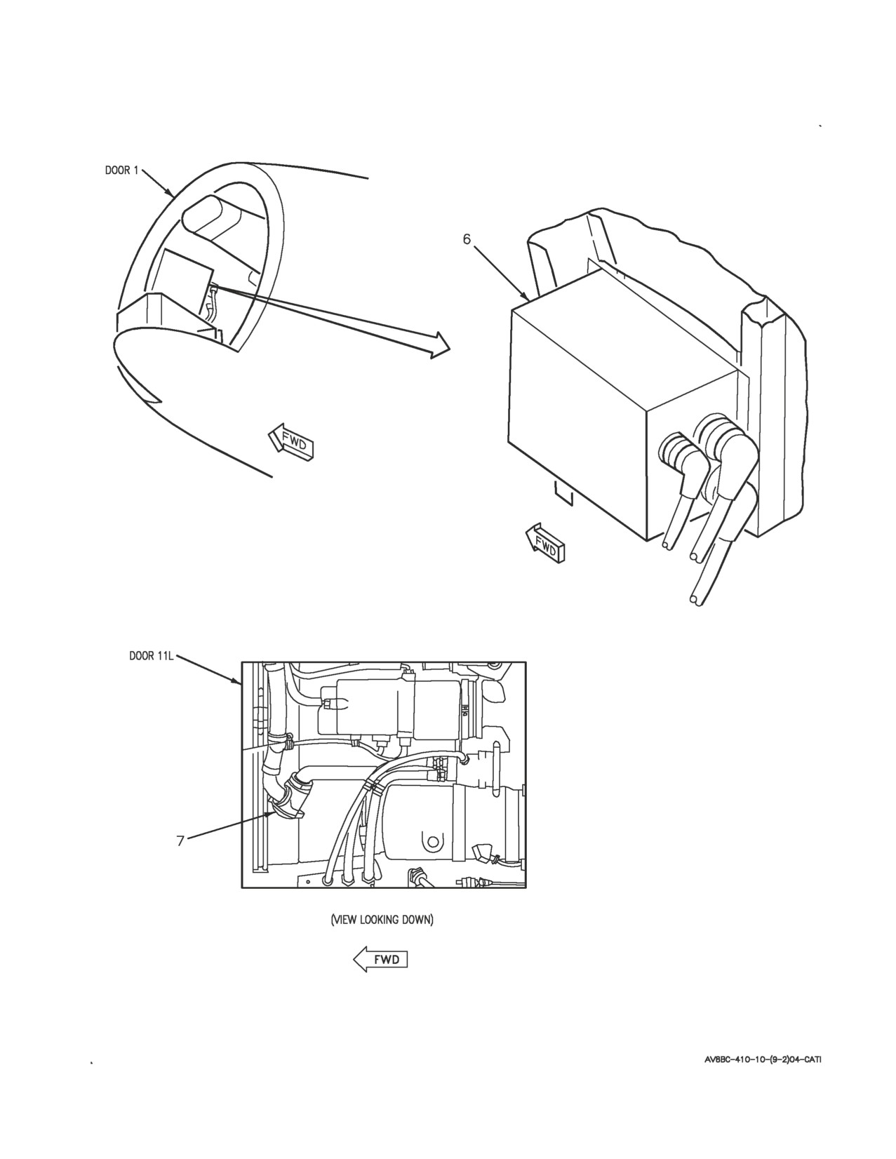
A1-AV8BC-410-100
005 00
Change 7
Page 3
Figure 1. Cabin Cooling and Defog System Component Locator (Sheet 2)
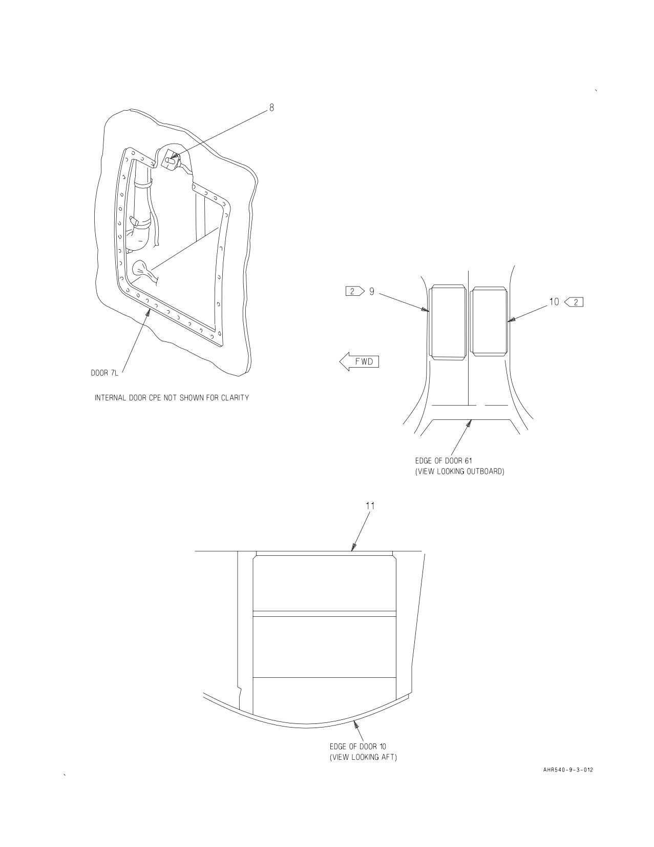
A1-AV8BC-410-100
005 00
Change 7
Page 4
Figure 1. Cabin Cooling and Defog System Component Locator (Sheet 3)
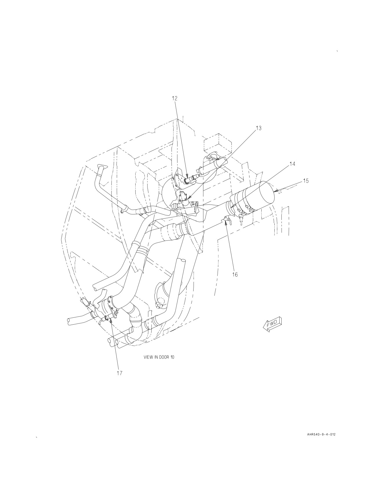
A1-AV8BC-410-100
005 00
Change 7
Page 5
Figure 1. Cabin Cooling and Defog System Component Locator (Sheet 4)
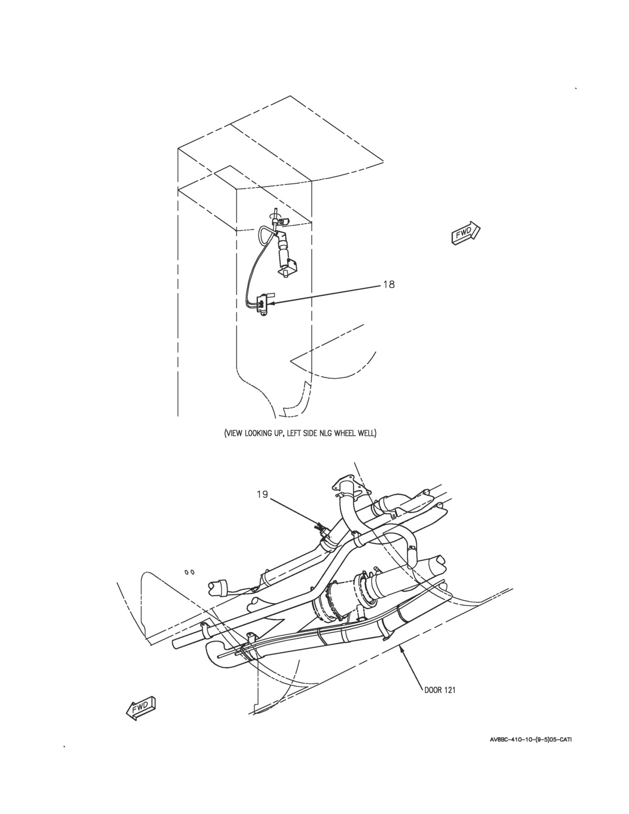
A1-AV8BC-410-100
005 00
Change 7
Page 6
Figure 1. Cabin Cooling and Defog System Component Locator (Sheet 5)
A1-AV8BC-410-100
005 00
Change 7
Page 7
Figure 1. Cabin Cooling and Defog System Component Locator (Sheet 6)
A1-AV8BC-410-100
005 00
Change 7
Page 8
Figure 1. Cabin Cooling and Defog System Component Locator (Sheet 7)

A1-AV8BC-410-100
005 00
Change
7
Page
9
Nomenclature
Index No.
Ref Des
ANNUNCIATOR LIGHT CONTROLLER
6
27A-D007
BULKHEAD MOUNTED EQUIPMENT COOLING
37
—
NOZZLE
CABIN ECS AIR FILTER ASSEMBLY
7
22FAJ506
CABIN ECS CHECK VALVE
14
22MAD509
CABIN ECS PRESSURE REGULATING AND
20
22L-K021
SHUTOFF VALVE
CABIN TEMPERATURE SENSOR
8
22R-E045
CAUTION/ADVISORY INDICATOR LIGHT
3
27A-F011
ASSEMBLY
WSHLD CAUTION LIGHT
—
COLD AIR UNIT
25
22MAK507
1
DC CIRCUIT BREAKER PANEL ASSEMBLY
1
52A-C104
CABIN ECS NO. 2 (ZONE B3)
22CBC015
CAB ECS NO. 1 (ZONE D7)
22CBC016
CKPT TEMP RLY (ZONE B12)
22CBC041
VENT/DEFOG (ZONE D8)
22CBC068
2
DC EMERGENCY PANEL ASSEMBLY
10
52A-P132
CABIN ECS CB NO. 2 (ZONE F8)
22CBP015
CKPT TEMP RELAY (ZONE F10)
22CBP068
2
DC ESSENTIAL/MAIN PANEL ASSEMBLY
9
52A-P133
CABIN ECS CB NO. 1 (ZONE D3)
22CBPO16
VENT/DEFOG (ZONE E5)
22CBP068
DEFOG SHUTOFF VALVE
13
22L-D100
DUCT TEMPERATURE SENSOR
16
22R-D046
ECS CONTROL PANEL ASSEMBLY
5
22A-F048
CABIN SWITCH
22S-F017
CABIN TEMPERATURE CONTROL
22A-F042
PRESS SWITCH
22S-F033
ECS PRESSURE SWITCH
26
22S-K101
FIXED CANOPY VENTILATION NOZZLES
28
—
FORWARD RELAY NO. 1 PANEL ASSEMBLY
11
52A-C015
WINDSHIELD OVERTEMPERATURE RELAY
22K-C052
MAX DEFOG RELAY
22K-C053
Figure 1. Cabin Cooling and Defog System Component Locator (Sheet
8)

A1-AV8BC-410-100
005 00
Change
7
Page
10
Nomenclature
Index No.
Ref Des
FORWARD RELAY NO. 2 PANEL ASSEMBLY
2
52A-C113
WEIGHT ON WHEELS RELAY NO. 1
12K-C053
FORWARD VENT/DEFOG VALVE
17
22L-D019
LEFT CENTER ECS LOUVER
35
—
LEFT ECS LOUVER
33
—
PRIMARY HEAT EXCHANGER
21
—
REAR BULKHEAD MOUNTED EQUIPMENT
38
—
COOLING NOZZLE
REAR CAUTION/ADVISORY INDICATOR LIGHT
4
27A-H045
ASSEMBLY
WSHLD CAUTION LIGHT
—
REAR LEFT CENTER ECS LOUVER
36
—
REAR LEFT ECS LOUVER
34
—
REAR RIGHT CENTER ECS LOUVER
30
—
REAR RIGHT ECS LOUVER
32
—
REAR VENT/DEFOG VALVE
12
22L-C096
RIGHT CENTER ECS LOUVER
29
—
RIGHT ECS LOUVER
31
—
SECONDARY HEAT EXCHANGER
23
—
SKIN TEMPERATURE SENSOR
18
22R-B044
TEMPERATURE REGULATING VALVE
24
22L-K043
VENTURI/CHOKE
22
—
WATER SEPARATOR
15
22MAD508
WINDSHIELD DEFOG NOZZLES
27
—
WINDSHIELD OVERTEMPERATURE SWITCH
19
22S-D018
LEGEND
1
162747; ALSO 162963 THRU 163861 BEFORE AV8AFC-416.
2
164113 AND UP; ALSO 162963 THRU 163861 AFTER AV8AFC-416.
Figure 1. Cabin Cooling and Defog System Component Locator (Sheet
9)
A1-AV8BC-410-100
006 00
Change 7 - 15 May 2004
Page 1
ORGANIZATIONAL MAINTENANCE
PRINCIPLES OF OPERATION
CABIN PRESSURIZATION SYSTEM
Reference Material
Electrical Systems
A1-AV8BB-420-100
DC Power System
WP004 00
Electrical Systems
A1-AV8BD-420-100
DC Power System
WP004 00
Environmental Control System
A1-AV8BC-410-100
Canopy Seal System
WP007 00
Description and Operation - Cabin Cooling and Defog System
WP004 00
Lighting Systems
A1-AV8BB-440-100
Interior Lighting System
WP005 00
Ejection Seat and Canopy System
A1-AV8BB-120-100
Canopy System Description and Operation
WP007 00
Alphabetical Index
Subject
Page No.
Cabin Pressurization System Component Locator, Figure 1
7
Cabin Pressurization System Simplified Schematic, Figure 2
12
Description
2
Component Description
2
Cabin Dump Control Valve
2
Cabin Inlet Pressure Test Port
3
Cabin Pressure Regulator
2
Cabin Pressure Regulator and Safety Relief Check Valves
2
Cabin Static Pressure Test Port
3
Pressurized Compartment Altimeter AAU-38/A
2
Safety Relief Valve
3
Related Systems
3
Aircraft Structure
3
Cabin Cooling and Defog System
3
Canopies
3
Canopy Seal System
3
DC Power System
3
Interior Lighting System
3
System Controls and Indicators
3
Ground Test Valve
3
PRESS Switch
3
Pressurized Compartment Altimeter AAU-38/A
3
System Description
2
A1-AV8BC-410-100
006 00
Change 7
Page 2
Alphabetical Index (Continued)
Subject
Page No.
Operation
4
Component Operation
4
Cabin Dump Control Valve
4
Cabin Inlet Pressure Test Port
5
Cabin Pressure Regulator
4
Cabin Pressure Regulator Check Valve
4
Cabin Static Pressure Test Port
5
Safety Relief Check Valve
4
Safety Relief Valve
5
System Operation
5
Dump
6
Ground Test
6
Normal Flight
5
Record of Applicable Technical Directives
Type/
Date
Date
Title and ECP or RAMEC No.
Remarks
Number
Incorp.
AV8AFC-416
— TAV-8B Polyimide Wire Replacement/
15 May 04
—
Power Wire Separation (ECP MDA-AV8B-
0277)
1. DESCRIPTION.
check valves. The valve body is threaded at each
end.
2. SYSTEM DESCRIPTION. The cabin is
pressurized by conditioned air from the cabin
6. Cabin Pressure Regulator. The cabin pressure
cooling and defog system (WP004 00) to provide a
regulator is an outflow valve and a self contained
comfortable, less fatiguing environment for the
controller in a single unit. The outflow valve is
pilot. Pressurization is done by controlling the rate
made up of a base, outflow valve, actuator
of airflow from the sealed cabin. The airflow is
diaphragm, valve return spring, and a control
routed to equipment bays, where it augments
chamber. The base includes the valve seat and
avionics cooling.
forms the passage for discharge air from the
pressurized area. The controller is made up of an
3. COMPONENT DESCRIPTION. System
orifice, filter, ground test valve, and two control
components shown in figure 1 are described and
systems: the isobaric control system and the
listed in paragraphs below.
differential control system.
4. Cabin Dump Control Valve. The cabin dump
7. Pressurized Compartment Altimeter AAU-38/A.
control valve is a solenoid operated, two position air
The Pressurized Compartment Altimeter AAU-38/A
control valve. The valve is made up of a body with
is a self contained aneroid, single pointer, integrally
inlet and outlet connections and a solenoid with an
lighted instrument. The altimeter measures and
electrical connection. The solenoid is mounted to
indicates cabin pressure from 0 to 50,000 feet. The
the valve body.
altimeter face is graduated every 1000 feet, major
increments each 5000 feet, and markings at the
5. Cabin Pressure Regulator and Safety Relief
even major increments.
Check Valves. The cabin pressure regulator and
safety relief check valves are poppet type, in line
A1-AV8BC-410-100
006 00
Change 7
Page 3
8. Safety Relief Valve. The safety relief valve is an
AFTER AV8AFC-416 (A1-AV8BD-420-100, WP004
outflow valve made up of a head section and a base
00) supplies emergency 28vdc power for the cabin
section. The head section consists of a pressure
pressurization system.
relief metering valve, pressure relief calibration
18. SYSTEM CONTROLS AND INDICATORS.
spring and two pressure relief control diaphragms.
System controls and indicators are described in
The base section consists of an outflow valve,
paragraphs below.
mounting base and operating mechanism. The
outflow valve provides the passage for discharge air
19. PRESS Switch. The PRESS switch, located on
from the pressurized area.
the ECS control panel assembly, is a four pole lever
lock toggle switch. The switch provides mode
9. Cabin Inlet Pressure Test Port. The cabin inlet
selection for cabin pressurization and on/off control
pressure test port is a capped port installed through
of the cabin cooling and defog system. Refer to
the rear cockpit floor.
WP004 00 for cabin cooling and defog system. The
switch has three positions; NORM, DUMP, and
10. Cabin Static Pressure Test Port. The cabin
RAM. The switch is locked in all positions.
static pressure test port is a capped port installed
through the rear cockpit floor.
20. Setting the switch to DUMP or RAM from
NORM, applies emergency 28vdc power to energize
11. RELATED SYSTEMS. Related systems are
the cabin dump control valve.
described in paragraphs below.
21. Setting the switch to NORM from RAM or
12. Cabin Cooling and Defog System. The cabin
DUMP, removes emergency 28vdc power to
cooling and defog system (WP004 00) provides
deenergize the cabin dump control valve.
conditioned air to pressurize the cabin. Air enters
the sealed cabin through the cockpit ECS louvers,
22. Pressurized Compartment Altimeter
windshield defog nozzles and fixed canopy
AAU-38/A. The Pressurized Compartment
ventilation nozzles.
Altimeter AAU-38/A is located in the cockpit on the
right vertical console. The altimeter senses and
13. Canopy Seal System. The canopy seal system
indicates cabin altitude. Cabin altitude is artificially
(WP007 00) provides an inflatable seal interface
created by the cabin pressurization system by
between the forward canopy, aft canopy, windshield
regulating pressurized air exiting the sealed cabin.
arch, fixed canopy, and aircraft structure.
The altimeter has an aneroid (evacuated bellows)
which expands and contracts in response to sensed
14. Interior Lighting System. The interior lighting
changes in pressure. As the aneroid moves, a
system (A1-AV8BB-440-100, WP005 00) provides
mechanical linkage moves the pointer to indicate
illumination for the Pressurized Compartment
cabin altitude.
Altimeter AAU-38/A. Rotating the CONSL control,
on the INTR LT control panel, varies altimeter
23. The pilot can use the cabin altitude to compare
lighting from off to bright. A lights test function is
with aircraft altitude. With this comparison, the
also provided.
pilot can determine whether the cabin is over,
under, or correctly pressurized.
15. Aircraft Structure. Cockpit floors, aft seat
24. Illumination of the altimeter is provided by the
bulkhead, aircraft side skins, forward pressure
interior lighting system.
bulkhead, windshield, and fixed canopy provide the
pressurized area.
25. Ground Test Valve. The ground test valve,
located on the face of the cabin pressure regulator,
16. Canopies. The forward and aft canopies
is a manually operated three position selector valve.
(A1-AV8BB-120-100, WP007 00), when locked
The valve handle is rotated to select normal flight
closed, complete the pressurized area.
or test positions. The three settings are FLIGHT,
TEST ONLY DIFF ON, and TEST ONLY ALL
17. DC Power System. The DC power system on
OFF.
162747; ALSO 162963 THRU 163861 BEFORE
AV8AFC-416 (A1-AV8BB-420-100, WP004 00) or
26. The FLIGHT position is used to provide
164113 AND UP; ALSO 162963 THRU 163861
automatic in-flight cabin pressurization control.
A1-AV8BC-410-100
006 00
Change 6
Page 4
Cabin pressure will maintain the prescribed
33. With the valve energized, cabin pressure
schedule as the aircraft altitude increases or
regulator and safety relief valve control chamber
decreases. The valve handle is lockwired to the
pressure is lost. Spring tension will open both
FLIGHT position.
regulator and relief valve allowing cabin pressure to
dump.
27. The TEST ONLY DIFF ON position is used to
test the differential control portion of the cabin
34. Cabin Pressure Regulator Check Valve. The
pressure regulator. Setting the handle to this
cabin pressure regulator check valve is located in
position, renders the isobaric control portion of the
door 1 in the cabin pressure regulator atmospheric
regulator inoperative by closing the isobaric
vent line. The check valve will prevent a dual
metering valve outlet. Only the differential control
failure if the safety relief valve fails or leaks
portion will operate.
internally.
28. The TEST ONLY ALL OFF position is used to
35. The cabin pressure regulator and safety relief
test safety relief valve operation. Setting the handle
valve control chambers are connected
to this position renders both the isobaric and
pneumatically. Without the check valve installed in
differential control positions of the regulator
the atmospheric vent line, if the safety relief valve
inoperative by closing both the isobaric and
failed or developed an internal leak, regulator
differential metering valve outlets. The regulator
control chamber pressure would also be lost. The
will not operate and cabin pressure will be
check valve prevents control chamber pressure loss.
controlled by the safety relief valve.
36. Safety Relief Check Valve. The safety relief
29. OPERATION.
check valve is located in the rear cockpit under the
right vertical console in the atmospheric port of the
30. COMPONENT OPERATION.
safety relief valve. The check valve will prevent a
dual failure if the cabin pressure regulator fails or
NOTE
leaks internally.
During normal operation of the cabin
37. The safety relief valve and cabin pressure
pressurization system, cabin pressure is
regulator control chambers are connected
controlled by air pressure measured in
pneumatically. Without the check valve installed in
pounds per square inch (psi). Cabin
the atmospheric vent line, relief valve control
pressure is the difference between cabin
chamber pressure would be lost if the regulator
atmospheric pressure and ambient
developed an internal leak or failed. The check
atmospheric pressure, expressed in
valve prevents control chamber pressure loss.
pounds per square inch differential
(psid). The psid value is used only during
38. Cabin Pressure Regulator. The cabin pressure
ground testing of the system. During
regulator, located outside the pressurized
normal flight, the cabin pressure is
compartment in door 1, automatically controls cabin
expressed as pressure altitude.
pressure throughout the aircraft flight envelope.
The regulator has a three mode normal operating
31. Cabin Dump Control Valve. The cabin dump
capability and a two mode ground test capability.
control valve is located in the rear cockpit under
the right vertical console. The valve is connected
39. During normal flight, the regulator ground test
pneumatically to the cabin pressure regulator and
valve handle is set to FLIGHT. This allows the
safety relief valve. The valve allows the pilot to
regulator to operate in its three normal modes;
rapidly remove (dump) cabin pressure, if required.
unpressurized, isobaric, and differential.
32. Valve operation is controlled by the PRESS
40. In the unpressurized mode, pressure in the
switch. With the valve deenergized, spring pressure
cabin is maintained slightly higher than
in the valve closes the valve poppet. The poppet
atmospheric pressure. The unpressurized mode is
prevents control chamber pressure in the cabin
from sea level to approximately 8000 feet. Control
pressure regulator and safety relief valve from
chamber pressure is enough to compress the
venting to atmosphere. This allows normal
isobaric bellows, keeping the isobaric metering valve
operation of the regulator and relief valve.
open to the atmosphere. Control chamber pressure
A1-AV8BC-410-100
006 00
Change 6
Page 4A/(4B blank)
is cabin air that has entered the control chamber
the amount of air venting from the cabin is less
through the air filter and orifice. Since the orifice is
than the amount of air entering the cabin, cabin
smaller than the open isobaric metering valve port,
pressure will be slightly higher than ambient
control chamber pressure is slightly lower than
pressure. This mode will function until the aircraft
outflow valve spring tension. The outflow valve will
altitude is approximately 8000 feet. The isobaric
remain open, venting cabin air to atmosphere. Since
mode will then function.
A1-AV8BC-410-100
006 00
Page 5
41. In the isobaric mode, cabin pressure is
diaphragm overrides the pressure relief calibration
maintained at a pressure equal to approximately
spring. The metering valve assembly moves and the
8000 feet while aircraft altitude is approximately
metering valve is off seated by the pressure relief
8000 to 23,100 feet.
calibration screw. The open metering valve vents
the control chamber and allows the outflow valve
42. Control chamber pressure constantly decreases
return spring to open the outflow valve and vent
with an increase in aircraft altitude. The decreased
excess cabin pressure. The safety relief valve works
control chamber pressure cannot compress the
with smooth modulation rather than erratic relief.
isobaric bellows as much and the isobaric metering
bellows begin to close. As metering valve closes, less
48. Negative pressure is ambient pressure greater
control chamber pressure is vented. Pressure
than cabin pressure. This occurs during rapid
coming into the control chamber through the orifice
aircraft descent. Normal operation of the system
and pressure venting to atmosphere through the
cannot always react to change cabin pressure as fast
now closing metering valve is balanced as aircraft
as the aircraft can descend. When this occurs, the
altitude increases from 8000 to approximately
safety relief valve will open and allow ambient
23,100 feet. The balanced pressures allow the cabin
pressure to enter the cabin to equalize pressure.
pressure regulator to maintain a constant cabin
pressure in the isobaric mode.
49. The higher ambient pressure overrides the
lower cabin and control chamber pressure and
43. As aircraft altitude increases above
outflow valve return spring. The higher ambient
approximately 23,100 feet, the isobaric metering
pressure moves the outflow valve open to allow
valve is fully closed. Closing the metering valve
ambient pressure to enter the cabin. As the
builds sufficient control chamber pressure to begin
pressures equalize, the outflow valve will close
the differential mode of operation.
under pressure from the outflow valve return
spring.
44. In the differential mode, cabin pressure is
maintained at a constant differential pressure
50. Cabin Inlet Pressure Test Port. The cabin inlet
versus ambient pressure. The constant differential
pressure test port is located in the nose landing gear
pressure is 5.00 ±0.23 psid.
wheelwell. The test port allows a ground air source
and a cabin pressure tester to be used for ground
45. As aircraft altitude exceeds approximately
testing of the cabin pressurization system. The test
23,100 feet, the increasing control chamber pressure
port allows the external air to enter the cabin.
overcomes spring tension and moves the differential
diaphragm mechanism. Moving the mechanism
51. Cabin Static Pressure Test Port. The cabin
opens the differential metering valve which vents
static pressure test port is located in the nose
control chamber pressure. The venting causes a
landing gear wheelwell. The test port allows a
lower control chamber pressure which allows spring
ground air source and a cabin pressure tester to be
tension to open the outflow valve. The open valve
used for ground testing of the cabin pressurization
vents enough cabin pressure to maintain a constant
system. The test port allows the cabin pressure to
differential pressure of 5.00 ±0.23 psid between
be measured externally.
cabin and ambient.
52. SYSTEM OPERATION.
46. Safety Relief Valve. The safety relief valve is
located in the rear cockpit under the right vertical
53. Conditioned air from the cabin cooling and
console. The valve will limit cabin pressure to 5.35
defog system (WP004 00) is controlled to maintain
±0.23 psid and provide negative pressure relief.
cabin pressure. The system operates in three modes,
normal flight, ground test, and dump.
47. Cabin pressure enters the control chamber
through the air filter screen. Control chamber
54. Normal Flight. During normal flight, air
pressure overrides outflow valve return spring
pressure entering the cabin also enters the control
tension and holds the outflow valve closed through
chambers of the cabin pressure regulator and the
the cabin pressure schedule. As control chamber
safety relief valve. The relief valve will remain
pressure increases with cabin pressure to 5.35 ±0.23
closed until cabin pressure exceeds 5.35 ±0.23 psid.
psid, control chamber pressure acts on the metering
The control chamber pressure in the regulator is
valve assembly diaphragm. Pressure on the
not enough to close the outflow valve from sea level
A1-AV8BC-410-100
006 00
Page 6
to 8000 feet. Thus, cabin pressure will remain at
valve return spring opens the valve to equalize
slightly above ambient pressure until the aircraft
pressure.
arrives at 8000 feet.
59. Ground Test. The cabin pressure regulator has
55. As the aircraft reaches 8000 feet, cabin pressure
a ground test valve which allows the system to be
entering the regulator control chamber is enough to
tested on the ground. The ground test has two
act on the isobaric bellows which begins to move
modes, TEST ONLY DIFF ON and TEST ONLY
and close the isobaric metering valve. The closing
ALL OFF. The TEST ONLY DIFF ON mode
metering valve allows control chamber pressure to
allows the cabin pressure regulator to bypass the
build and close the outflow valve as required to
unpressurized and isobaric modes and maintain
maintain a cabin altitude of 8000 feet while aircraft
cabin pressure at the 5.00 ±0.23 psid differential
altitude increases from 8000 to 23,100 feet.
mode. The TEST ONLY ALL OFF mode allows the
safety relief valve to regulate cabin pressure at 5.35
56. As the aircraft reaches 23,100 feet, cabin
±0.23 psid and bypass the regulator setting entirely.
pressure entering the regulator control chamber has
fully closed the isobaric metering valve and begins
60. During ground testing, an external air source
to open the differential metering valve. The opening
and special test equipment is required. Three test
differential metering valve vents control chamber
fittings are located in the nose landing gear
pressure to allow the regulator to maintain 5.00
wheelwell for test equipment hookup. One port
±0.23°ba psid between cabin and ambient pressure.
provides an air inlet to the cabin, one provides
This schedule is maintained from 23,100 feet and
cabin pressure sensing, and one provides pressure to
higher.
the canopy pressure seal. Refer to WP007 00 for
canopy seal system.
57. If cabin pressure exceeds the regulator setting,
the safety relief valve will open and relieve pressure.
61. Dump. The dump mode allows all cabin
As cabin pressure increases to 5.35 ±0.23 psid,
pressure to be removed (dump) from the cabin. If
control pressure in the relief valve which has held it
fumes or smoke enter the cabin, the pilot can select
closed is vented and the outflow valve return spring
DUMP with the PRESS switch. This will open the
opens the valve.
cabin dump control valve, venting control chamber
pressure and opening the cabin pressure regulator
58. In the event of negative cabin pressure, (cabin
and relief valve. Cabin pressure drops and vents the
pressure less than ambient pressure) the lower
cabin. Selecting RAM with the PRESS switch will
control chamber pressure in the safety relief valve is
also dump cabin pressure and disable the cabin
not enough to hold the valve closed. The outflow
cooling and defog system (WP004 00).
A1-AV8BC-410-100
006 00
Page 7
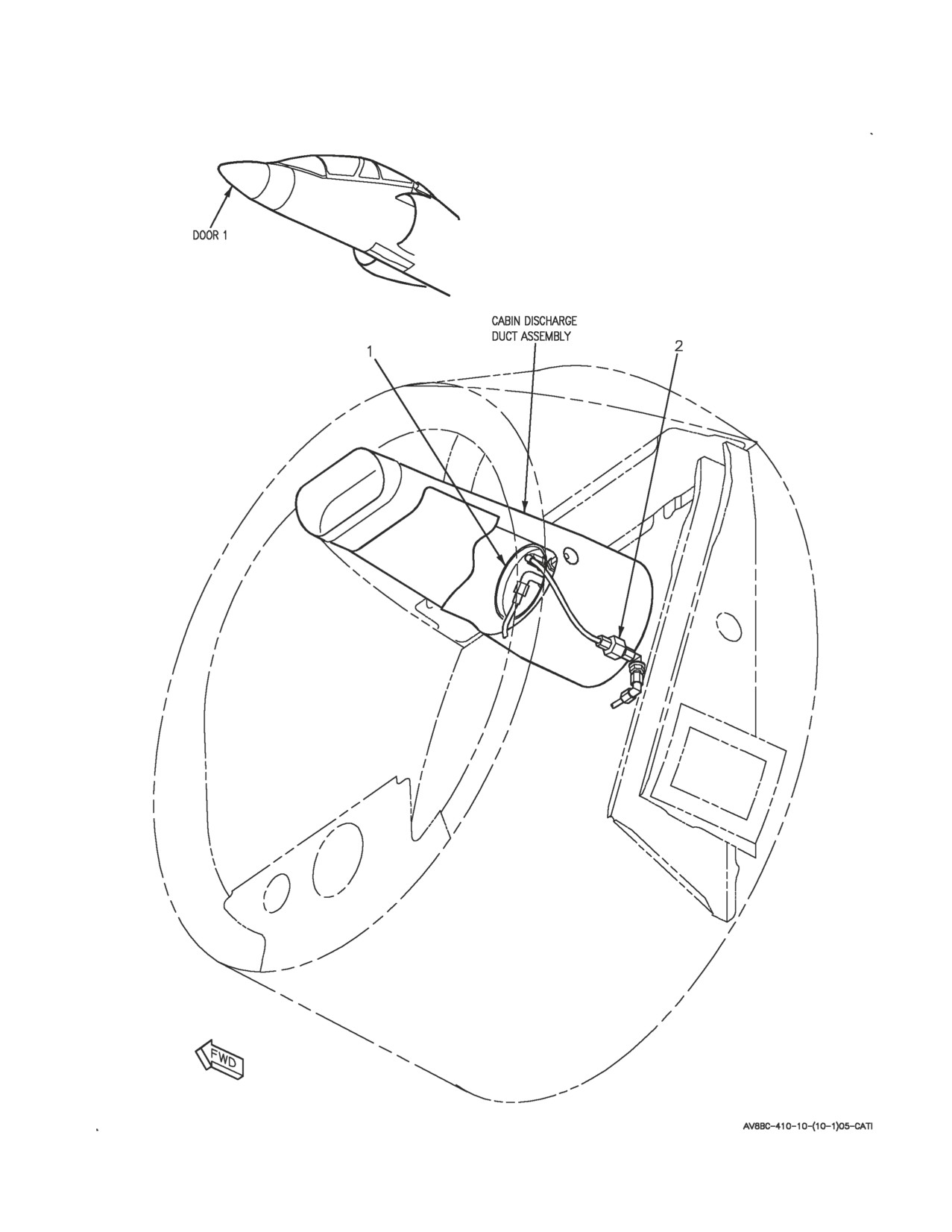
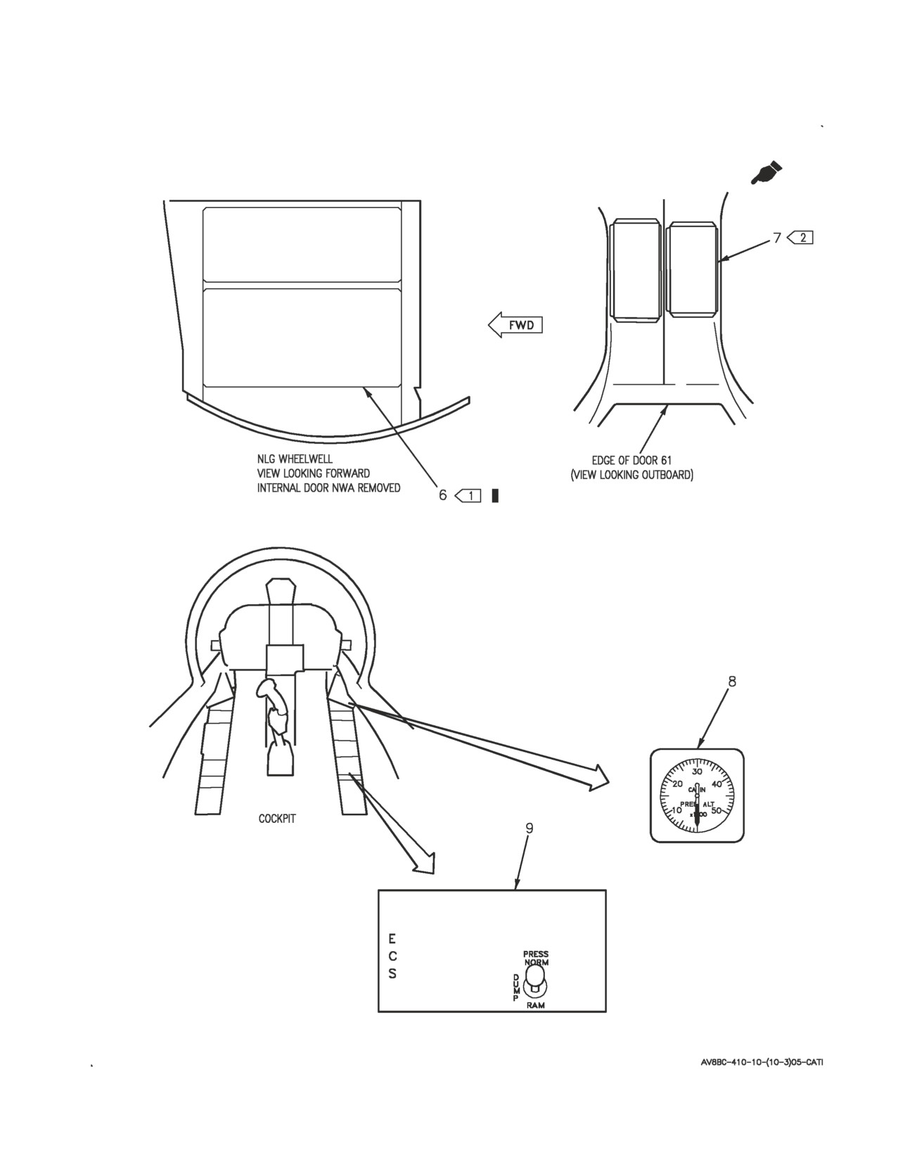
Figure 1. Cabin Pressurization System Component Locator (Sheet 1)

A1-AV8BC-410-100
006 00
Page 8
Figure 1. Cabin Pressurization System Component Locator (Sheet 2)
A1-AV8BC-410-100
006 00
Page 9
Figure 1. Cabin Pressurization System Component Locator (Sheet 3)
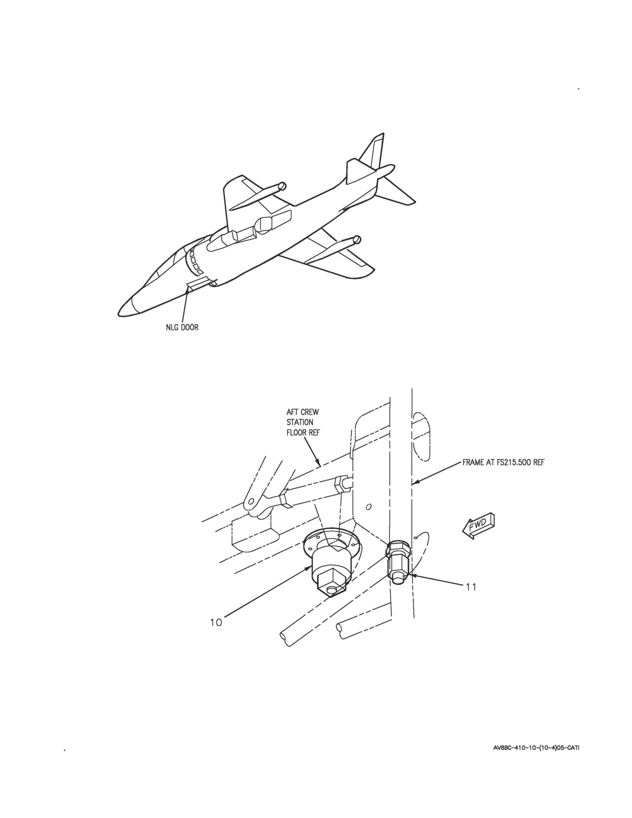
A1-AV8BC-410-100
006 00
Page 10
Figure 1. Cabin Pressurization System Component Locator (Sheet 4)

A1-AV8BC-410-100
006 00
Change
7
Page
11
Nomenclature
Index No.
Ref Des
CABIN DUMP CONTROL VALVE
3
22L-H034
CABIN INLET PRESSURE TEST PORT
10
—
CABIN PRESSURE REGULATOR
1
22VAA504
CABIN PRESSURE REGULATOR CHECK VALVE
2
22VAA501
CABIN STATIC PRESSURE TEST PORT
11
—
1
DC CIRCUIT BREAKER PANEL ASSEMBLY
6
52A-C104
CAB DMP CONT CB (ZONE B2)
22CBC032
2
DC EMERGENCY PANEL ASSEMBLY
7
52A-P132
CAB PRESS CONTROL CB (ZONE F9)
22CBP032
ECS CONTROL PANEL ASSEMBLY
9
22A-F048
PRESS SWITCH
22S-F033
PRESSURIZED COMPARTMENT ALTIMETER
8
8M-F072
AAU-38/A
SAFETY RELIEF CHECK VALVE
4
22VAH524
SAFETY RELIEF VALVE
5
22VAH525
LEGEND
1
162747; ALSO 162963 THRU 163861 BEFORE AV8AFC-416.
2
164113 AND UP; ALSO 162963 THRU 163861 AFTER AV8AFC-416.
Figure 1. Cabin Pressurization System Component Locator (Sheet 5)
A1-AV8BC-410-100
006 00
Page 12
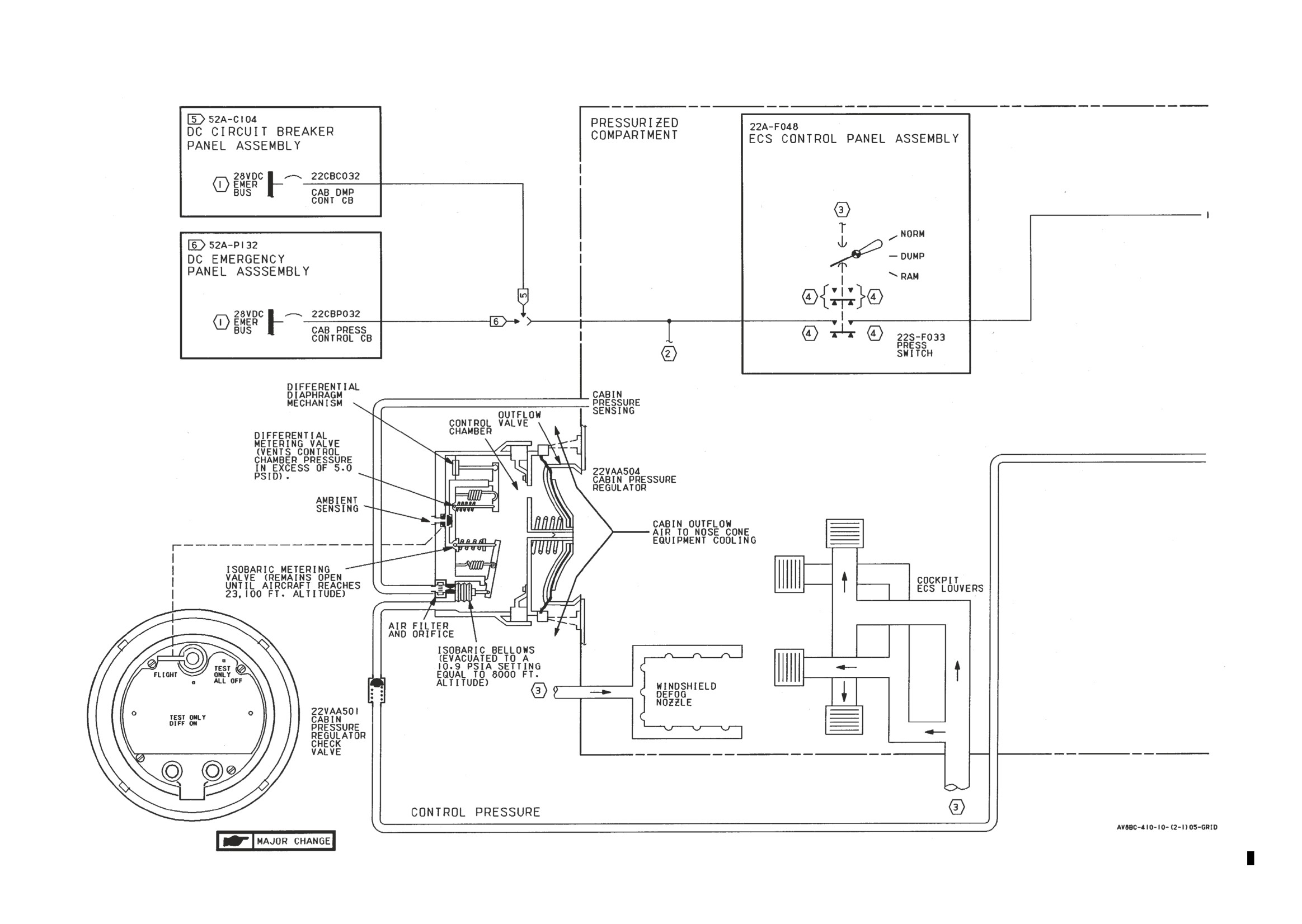
Figure 2. Cabin Pressurization System Simplified Schematic (Sheet 1)
Figure 2.
Figure 2.
A1-AV8BC-410-100
006 00
Change 7
Page 13/(14 blank)
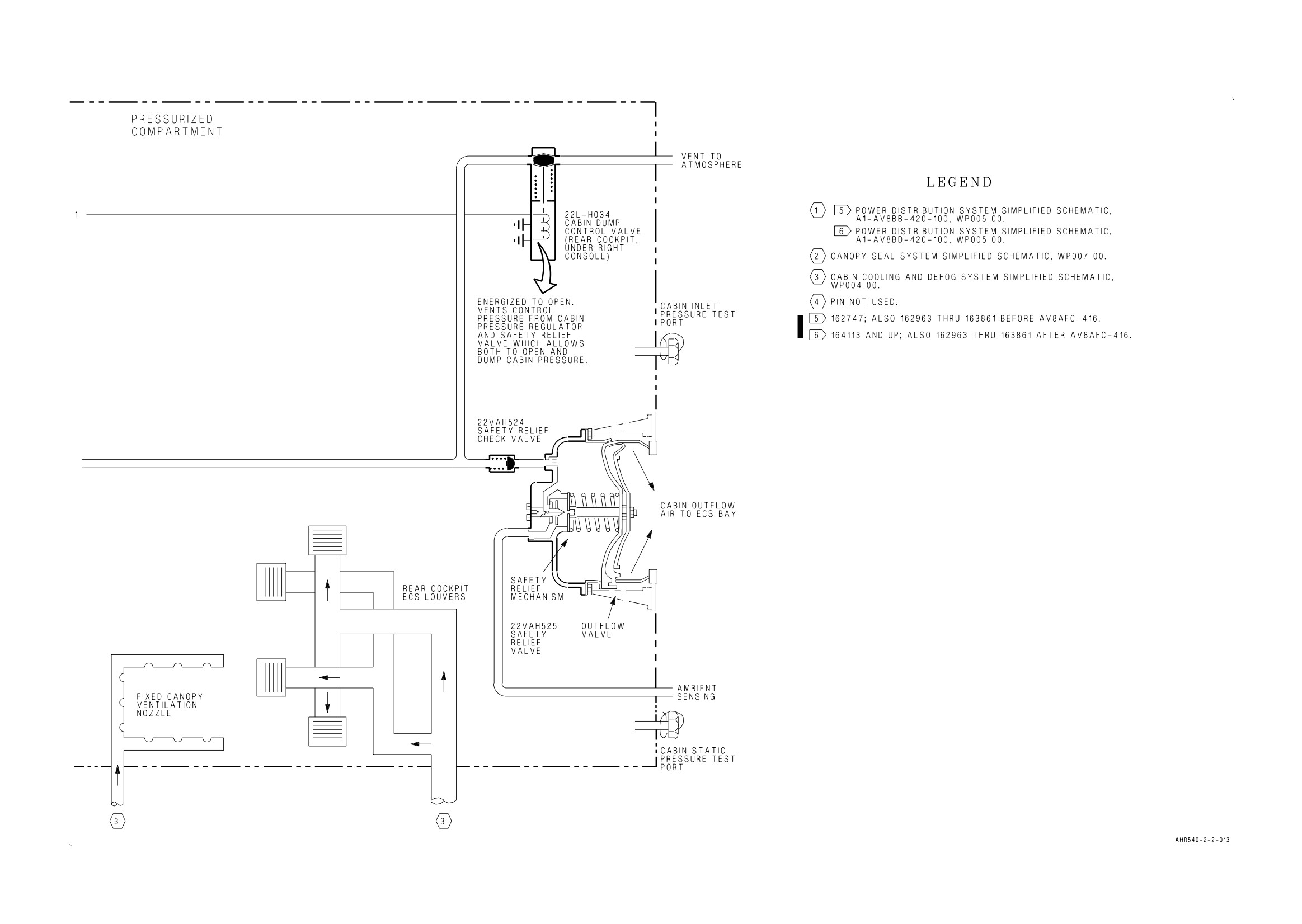
Figure 2. Cabin Pressurization System Simplified Schematic (Sheet 2)
Figure 2.
Figure 2.
A1-AV8BC-410-100
007 00
Change 7 - 15 May 2004
Page 1
ORGANIZATIONAL MAINTENANCE
PRINCIPLES OF OPERATION
CANOPY SEAL SYSTEM
Reference Material
Ejection Seat and Canopy System
A1-AV8BB-120-100
Canopy System Description and Operation
WP007 00
Environmental Control System
A1-AV8BC-410-100
Description and Operation - Cabin Cooling and Defog System
WP004 00
Description and Operation - Cabin Pressurization System
WP006 00
Description and Operation - Anti-G System
WP009 00
Electrical Systems
A1-AV8BB-420-100
DC Power System
WP004 00
Electrical Systems
A1-AV8BD-420-100
DC Power System
WP004 00
Landing Gear and Related Systems
A1-AV8BB-130-100
Landing Gear System
WP003 00
Alphabetical Index
Subject
Page No.
Canopy Seal System Component Locator, Figure 1
5
Canopy Seal System Simplified Schematic, Figure 2
10
Description
2
Component Description
2
Aft Canopy Pressure Seal
2
Anti-G/Canopy Seal Check Valve
2
Anti-G/Canopy Seal Test Port
2
Canopy Seal Control Valve
2
Canopy Seal Pressure Regulator and Check Valve
2
Forward Canopy Pressure Seal
2
Related Systems
2
Aircraft Structure
3
Cabin Cooling and Defog System
2
Canopy System
2
DC Power System
2A
Landing Gear and Related Systems
2A
System Control and Indicators
3
Press Switch
3
System Description
2
Operation
3
Component Operation
3
Aft Canopy Pressure Seal
3
Anti-G/Canopy Seal Check Valve
3
A1-AV8BC-410-100
007 00
Change 7
Page 2
Alphabetical Index (Continued)
Subject
Page No.
Anti-G/Canopy Seal Test Port
3
Canopy Seal Control Valve
3
Canopy Seal Pressure Regulator and Check Valve
4
Forward Canopy Pressure Seal
3
System Operation
4
Ground Operation
4
Normal Operation
4
Record of Applicable Technical Directives
Type/
Date
Date
Title and ECP or RAMEC No.
Remarks
Number
Incorp.
AV8AFC-416
— TAV-8B Polyimide Wire Replacement/
15 May 04
—
Power Wire Separation (ECP MDA-AV8B-
0277)
1. DESCRIPTION.
seal. The seal is made of silicone rubber reinforced
with polyester.
2. SYSTEM DESCRIPTION. The canopy seal
system provides a pressure regulated seal between
8. Canopy Seal Control Valve. The canopy seal
the windshield arch, canopy sills, forward canopy,
control valve is a solenoid operated, double acting
aft canopy, and fixed canopy. Pneumatic pressure
air control valve. The valve is made up of a solenoid
for the canopy seal system is supplied from the
and a valve body with inlet, outlet, and vent
cabin cooling and defog system (WP004 00) or from
connections.
an external air source through the anti-g/canopy
seal test port.
9. Canopy Seal Pressure Regulator and Check
Valve. The canopy seal pressure regulator and
3. COMPONENT DESCRIPTION. System
check valve is a pressure reducing valve, a check
components shown in figure 1 are described and
valve, and a pressure relief valve in a single unit.
listed in paragraphs below.
10. RELATED SYSTEMS. Related systems are
4. Anti-G/Canopy Seal Check Valve. The
described in paragraphs below.
anti-g/canopy seal check valve is a poppet type in
line check valve.
11. Cabin Cooling and Defog System. The cabin
cooling and defog system (WP004 00) provides
5. Anti-G/Canopy Seal Test Port. The
conditioned air to pressurize the forward and aft
anti-g/canopy seal test port is an in line capped tee.
canopy pressure seals. Conditioned air is tapped off
the outlet of the secondary heat exchanger. The air
6. Forward Canopy Pressure Seal. The forward
is transported by way of tubing to the canopy seal
canopy pressure seal is a single piece, tubular
system.
inflatable seal. The seal is made of silicone rubber
reinforced with polyester.
12. Canopy System. The forward and aft canopy
pressure seals are mounted in a track on the
7. Aft Canopy Pressure Seal. The aft canopy
periphery of each canopy (A1-AV8BB-120-100,
pressure seal is a single piece, tubular, inflatable
WP007 00).
A1-AV8BC-410-100
007 00
Change 7
Page 2A/(2B blank)
13. DC Power System. The DC power system on
14. Landing Gear and Related Systems. The
162747; ALSO 162963 THRU 163861 BEFORE
landing gear system (A1-AV8BB-130-100,
AV8AFC-416 (A1-AV8BB-420-100, WP004 00) or
WP003 00) provides a weight on wheels signal for
164113 AND UP; ALSO 162963 THRU 163861
the canopy seal system through the MLG weight on
AFTER AV8AFC-416 (A1-AV8BD-420-100, WP004
wheels (WOW) switch and the weight on wheels
00) supplies emergency 28vdc power for the canopy
relay no. 1.
seal system.
A1-AV8BC-410-100
007 00
Page 3
15. Aircraft Structure. The forward and aft canopy
valve. The system operates identically with either
pressure seals, when inflated, mate with and provide
the normal air source or ground air source in use.
a pressure seal between the canopy sills, windshield
arch, and fixed canopy.
25. Forward Canopy Pressure Seal. The forward
canopy pressure seal is installed in a track on the
16. SYSTEM CONTROLS AND INDICATORS.
periphery of the forward canopy. A flexible inlet
tube on the aft end of the seal connects the seal
17. PRESS Switch. The PRESS switch, located
pneumatically with the canopy seal system.
on the ECS control panel assembly, provides on/off
control for the cabin cooling and defog system
26. The seal is inflated to provide a pressure tight
(WP004 00) and mode selection for the cabin
air seal between the forward canopy sill, windshield
pressurization system (WP006 00). The switch has
arch, fixed canopy, and forward canopy frame. The
three positions; NORM, DUMP and RAM.
seal is inflated to approximately 20 ±1 psi with
regulated air from the canopy seal control valve.
18. Setting the PRESS switch to RAM applies
When inflated, the seal expands approximately 3/8
emergency 28vdc to energize the solenoid of the
inch. When deflated, the seal collapses into itself so
canopy seal control valve. With the canopy seal
not to interfere with canopy opening and closing.
control valve energized both canopy pressure seals
will deflate.
27. Aft Canopy Pressure Seal. The aft canopy
pressure seal is installed in a track on the periphery
19. OPERATION.
of the aft canopy. It is functionally identical to the
20. COMPONENT OPERATION.
forward canopy pressure seal.
21. Anti-G/Canopy Seal Check Valve. The
28. Canopy Seal Control Valve. The canopy seal
anti-g/canopy seal check valve is located between
control valve is located in door 10. The valve passes
the primary heat exchanger and the expansion
conditioned air to inflate the forward and aft
turbine inlet of the cold air unit (WP004 00). The
canopy pressure seals when deenergized and deflate
check valve allows air flow in one direction only.
the seals when energized.
With air pressure applied, spring tension is
overcome by air pressure and the check valve opens
29. The canopy seal control valve is energized
to allow air flow. With no air pressure applied, the
through the PRESS switch when set to RAM and
valve is held closed by spring tension, allowing no
the weight on wheels relay no. 1 when aircraft
reverse air flow. If cabin cooling and defog system
weight is on wheels. The energized solenoid opens a
pressure is lost, the check valve will hold canopy
vent and closes the supply to deflate the forward
seal system and anti-g system (WP009 00) pressure.
and aft canopy pressure seals.
22. The check valve also isolates the canopy seal
system for ground operation. With the normal air
30. The valve is deenergized with the PRESS
source off, a ground air source can be connected to
switch set to NORM or DUMP and through the
the anti-g/canopy seal test port. The check valve
weight on wheels relay no. 1 when aircraft is weight
will prevent loss of ground air source air through
off wheels. The deenergized solenoid closes a vent
the nonoperating normal system.
and opens the supply to inflate the forward and aft
canopy pressure seals.
23. Anti-G/Canopy Seal Test Port. The
anti-g/canopy seal test port is a capped tee located
31. The canopy seal control valve functions
in the nose wheelwell. The test port allows a ground
identically whether the air source is from the cabin
air source to be used for ground testing of the
cooling and defog system or from a ground air
canopy seal system.
source.
24. The test port is tapped into the anti-g/canopy
seal line between the anti-g/canopy seal check valve
32. If an electrical failure of the aircraft or valve
and the canopy seal pressure regulator and check
occurs, the valve solenoid will fail to the
valve. The ground air source connected to the test
deenergized position, allowing the canopy pressure
port is isolated by the anti-g/canopy seal check
seals to inflate.
A1-AV8BC-410-100
007 00
Page 4
33. Canopy Seal Pressure Regulator and Check
for normal operation. Conditioned air is tapped off
Valve. The canopy seal pressure regulator and
the air duct between the secondary heat exchanger
check valve is located in door 10. The valve
and the cold air unit. The air passes through the
regulates conditioned air from the cabin cooling and
anti-g/canopy seal check valve. The check valve
defog system (WP004 00) or air from a ground air
prevents loss of canopy seal system pressure if cabin
source to approximately 20 ±1 psi.
cooling and defog system pressure is lost. The air is
transported by way of tubing to the canopy seal
34. Air pressure enters the canopy seal pressure
pressure regulator and check valve where pressure is
regulator and check valve through the check valve.
regulated to 20 ±1 psi. The regulated air then passes
The air pressure acts on the diaphragm moving it
to the canopy seal control valve.
down against spring tension. Moving the diaphragm
down begins to move the inlet valve towards its
39. The canopy seal control valve is controlled
seat. The inlet valve will pass 20 ±1 psi. When the
electrically through the PRESS switch and the
air pressure acting on the diaphragm is above 20 ±1
weight on wheels relay no. 1.
psi, the inlet valve will be closed. Further increasing
pressure will move the diaphragm down away from
the relief valve plate. An opening in the diaphragm
40. With the PRESS switch set to NORM or
and spring cup will pass air pressure in excess of 20
DUMP and aircraft weight off wheels, the canopy
±1 psi to the pressure relief valve.
seal control valve is deenergized. Deenergizing the
control valve closes a vent and opens the supply
35. The check valve prevents loss of canopy
port allowing regulated air to pass through the
pressure seal pressure if the cabin cooling and defog
control valve and inflate both canopy pressure seals.
system or ground air source pressure is lost.
41. Setting the PRESS switch to RAM or with
36. SYSTEM OPERATION.
aircraft weight on wheels the control valve is
energized. Energizing the control valve closes the
37. The canopy seal system (figure 2), provides an
supply port and opens the vent. Air exits through
inflated seal between the canopies and surrounding
the vent and both canopy seals deflate.
structure. The forward canopy pressure seal and aft
canopy pressure seal can be inflated by one of two
42. Ground Operation. Ground operation of the
air sources; the cabin cooling and defog system or a
canopy seal system is the same as normal operation
ground air source.
except for the air source. For ground operation, the
anti-g/canopy seal test port is used to connect a
38. Normal Operation. The cabin cooling and
ground air source to the system.
defog system provides air to the canopy seal system
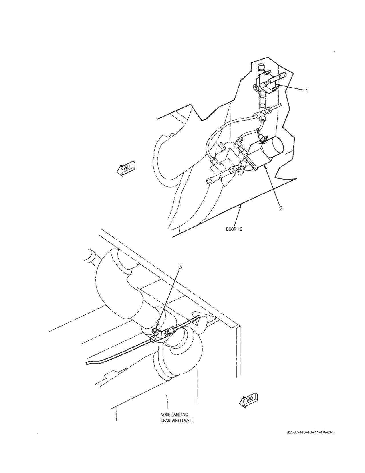
A1-AV8BC-410-100
007 00
Page 5
Figure 1. Canopy Seal System Component Locator (Sheet 1)
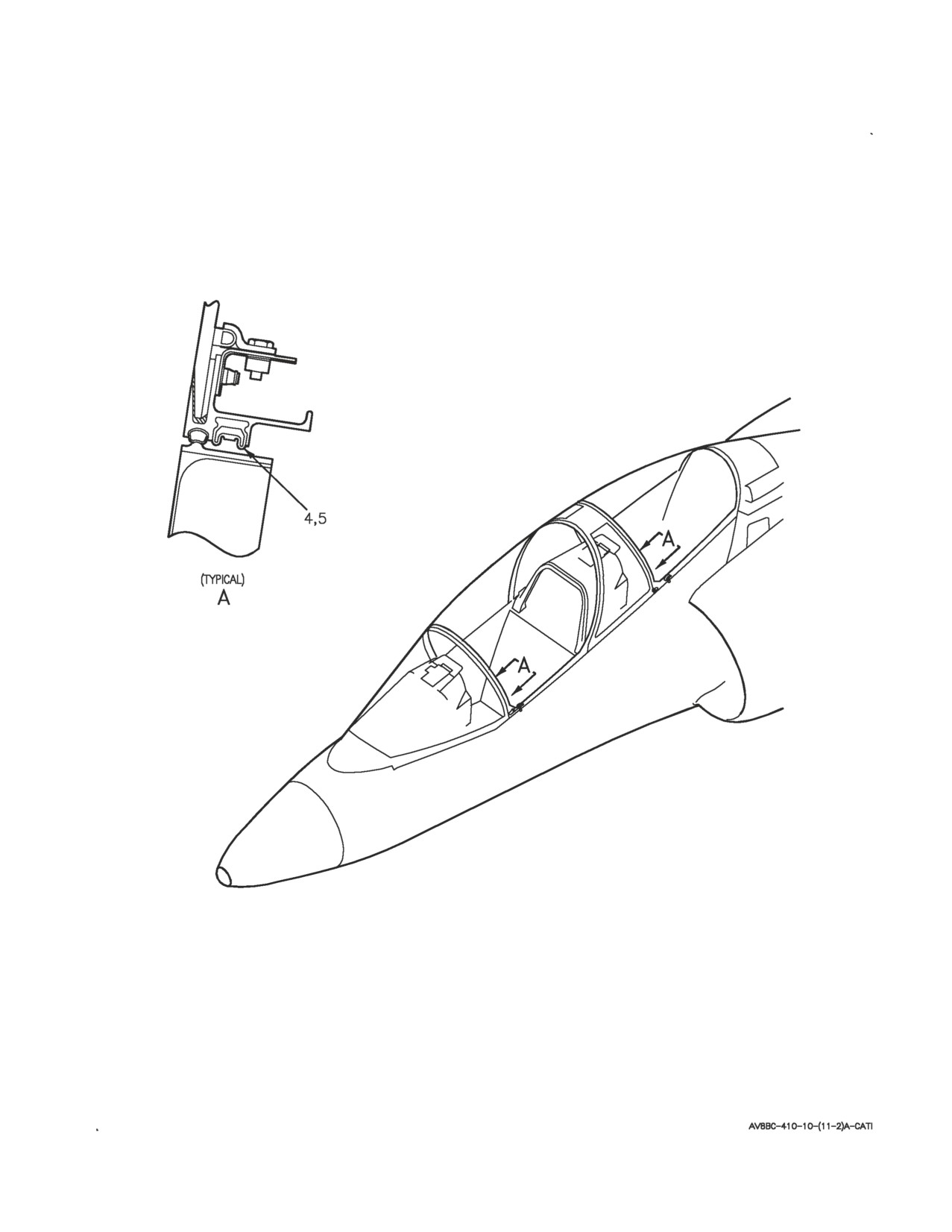
A1-AV8BC-410-100
007 00
Page 6
Figure 1. Canopy Seal System Component Locator (Sheet 2)
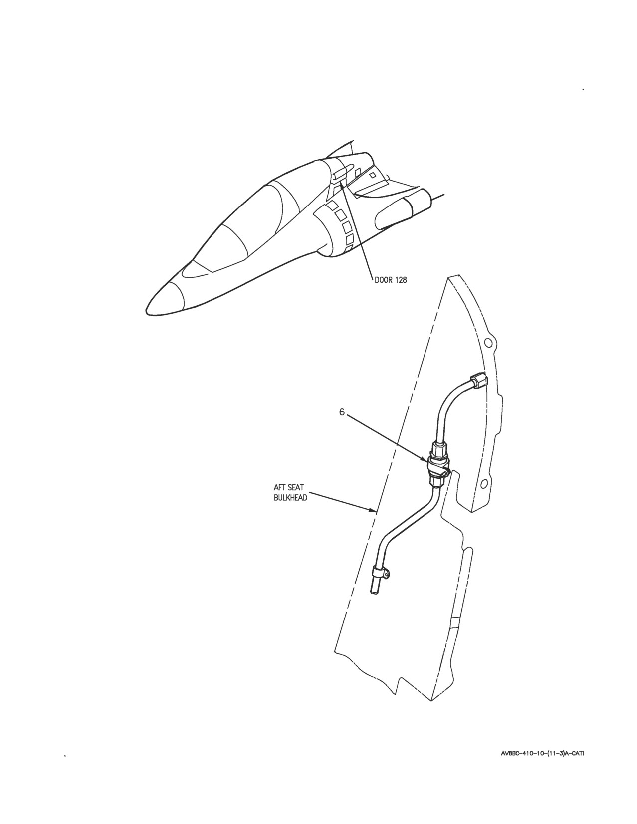
A1-AV8BC-410-100
007 00
Page 7
Figure 1. Canopy Seal System Component Locator (Sheet 3)
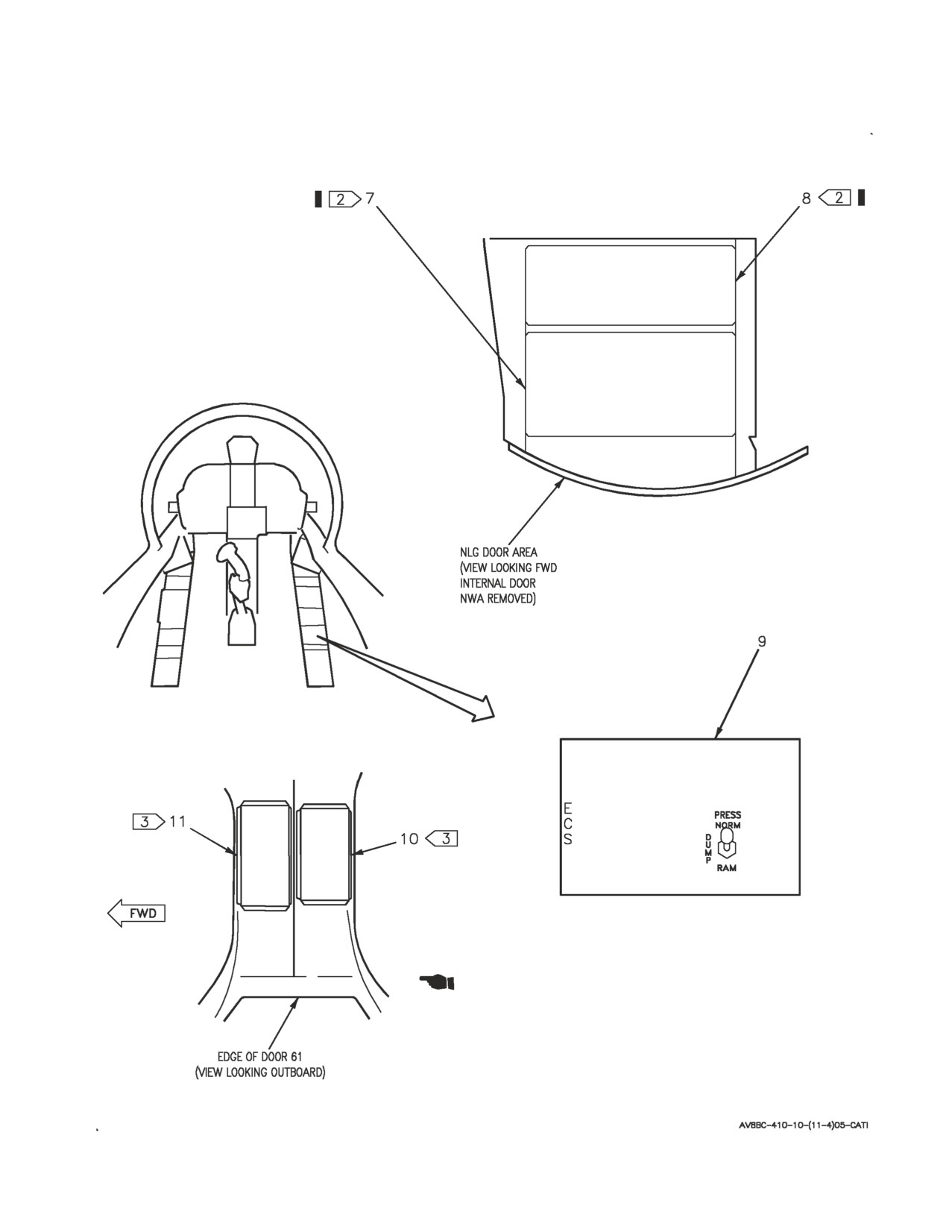
A1-AV8BC-410-100
007 00
Page 8
Figure 1. Canopy Seal System Component Locator (Sheet 4)

A1-AV8BC-410-100
007 00
Change
7
Page
9
Nomenclature
Index No.
Ref Des
AFT CANOPY PRESSURE SEAL
5
—
ANTI-G/CANOPY SEAL CHECK VALVE
6
22VAK516
CANOPY SEAL CONTROL VALVE
2
22L-D031
CANOPY SEAL PRESSURE REGULATOR AND
1
22MAJ514
CHECK VALVE
CANOPY SEAL WATER DRAIN VALVE
3
—
1
DC CIRCUIT BREAKER PANEL ASSEMBLY
7
52A-C104
CAB ECS NO. 1 (ZONE D7)
22CBC016
CABIN ECS NO. 2 (ZONE B3)
22CBC015
2
DC EMERGENCY PANEL ASSEMBLY
10
52A-P132
CABIN ECS CB NO. 2 (ZONE F8)
22CBP015
2
DC ESSENTIAL/MAIN PANEL ASSEMBLY
11
52A-P133
CABIN ECS CB NO. 1 (ZONE D3)
22CBP016
ECS CONTROL PANEL ASSEMBLY
9
22A-F048
PRESS SWITCH
22S-F033
FORWARD CANOPY PRESSURE SEAL
4
—
FORWARD NO. 2 RELAY PANEL ASSEMBLY
8
52A-C113
WEIGHT ON WHEELS RELAY NO. 1
12K-C053
LEGEND
1
162747; ALSO 162963 THRU 163861 BEFORE AV8AFC-416.
2
164113 AND UP; ALSO 162963 THRU 163861 AFTER AV8AFC-416.
Figure 1. Canopy Seal System Component Locator (Sheet 5)
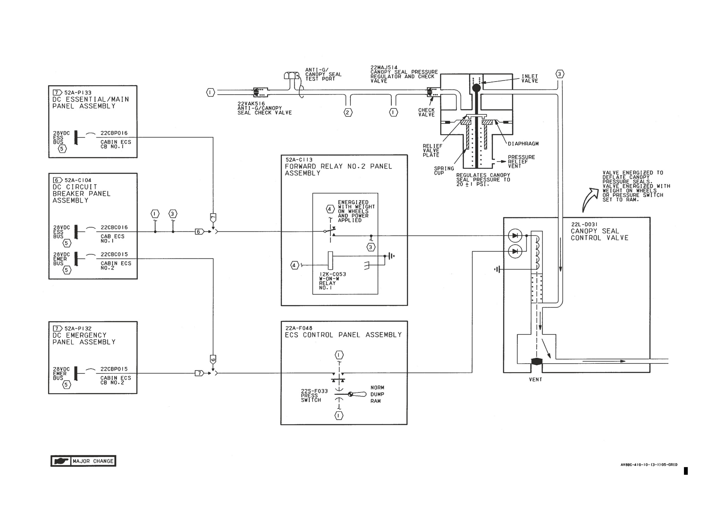
A1-AV8BC-410-100
007 00
Page 10
Figure 2. Canopy Seal System Simplified Schematic (Sheet 1)
Figure 2.
Figure 2.
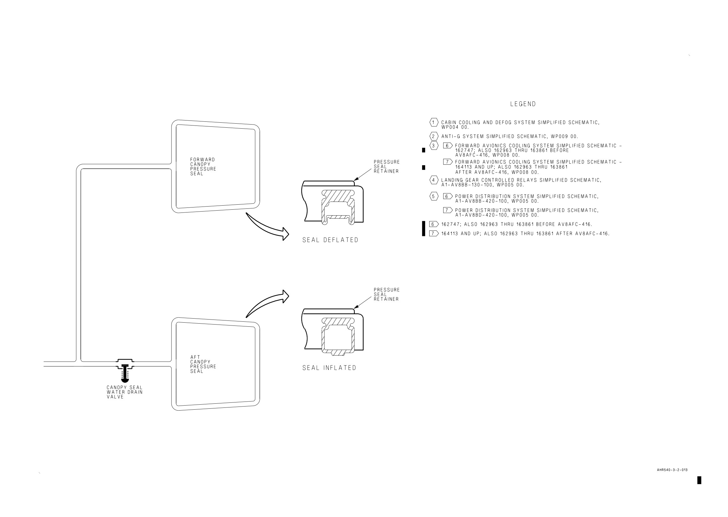
A1-AV8BC-410-100
007 00
Change 7
Page 11/(12 blank)
Figure 2. Canopy Seal System Simplified Schematic (Sheet 2)
Figure 2.
Figure 2.
A1-AV8BC-410-100
008 00
Change 7 - 15 May 2004
Page 1
ORGANIZATIONAL MAINTENANCE
PRINCIPLES OF OPERATION
FORWARD AVIONICS COOLING SYSTEM
Reference Material
Air Data Computer System
A1-AV8BB-560-100
Operation
WP005 00
Electrical Systems
A1-AV8BB-420-100
AC Power System
WP003 00
DC Power System
WP004 00
External Electrical Power System
WP006 00
Electrical Systems
A1-AV8BD-420-100
AC Power System
WP003 00
DC Power System
WP004 00
External Electrical Power System
WP006 00
Environmental Control System
A1-AV8BC-410-100
Description and Operation - Cabin Cooling and Defog System
WP004 00
Cabin Pressurization System
WP006 00
Landing Gear and Related Systems
A1-AV8BB-130-100
Landing Gear System
WP003 00
Lighting System
A1-AV8BB-440-100
Warning/Caution/Advisory Lighting System
WP007 00
Alphabetical Index
Subject
Page No.
Description
3
Component Description
3
Anti-G/Canopy Seal Test Port
3
Avionics Cooling Air Fittings
3
Cockpit Avionics Cooling Fan
3
Cockpit Differential Pressure Switch
3
Ground Cooling Control Valve
3
Ground Cooling Fan
3
Ground Cooling Valve
3
INS Check Valve
3
INS Plenum Check Valve
3
Ram Air Inlet
3
Ram Air Vent Check Valve
3
Rear Cockpit Avionics Cooling Fan
3
Speed Sensor
3
A1-AV8BC-410-100
008 00
Change 7
Page 2
Alphabetical Index (Continued)
Subject
Page No.
Related Systems
3
AC Power System
4
Air Data Computer System
4
Cabin Cooling and Defog System
3
DC Power System
4
External Electrical Power System
4
Landing Gear System
4
Warning/Caution/Advisory Lighting System
4
System Controls and Indicators
4
Cockpit Cool Cancel Relay
4
Cockpit Cooling Fan Relay
4
Cockpit Fan Fail Relay
4
CS COOL Caution Lights
5
Fwd Fus Cooling Fan Control Relay
5
Fwd Fus Fan Fail Relay
5
Gnd Pwr Fan Control Relay
5
PRESS Switch
4
Rear Cockpit Cool Cancel Relay
5
Rear Cockpit Cooling Fan Relay
5
Rear Cockpit Fan Fail Relay
5
System Description
3
Forward Avionics Cooling System Component Locator, Figure 1
9
Forward Avionics Cooling System Simplified Schematic-162747; ALSO 162963 THRU 163861
BEFORE AV8AFC-416, Figure 2
21
Forward Avionics Cooling System Simplified Schematic-164113 AND UP; ALSO 162963
THRU 163861 AFTER AV8AFC-416, Figure 3
30
Operation
6
Component Operation
6
Anti-G/Canopy Seal Test Port
6
Avionics Cooling Air Fittings
6
Cockpit Avionics Cooling Fan
6
Cockpit Differential Pressure Switch
7
Ground Cooling Fan
6
Ground Cooling Control Valve
6
Ground Cooling Valve
7
INS Check Valve
7
INS Plenum Check Valve
7
Ram Air Inlet
7
Ram Air Vent Check Valve
7
Rear Cockpit Avionics Cooling Fan
6
Speed Sensor
7
System Operation
7
Emergency Operation
7
Ground Operation
7
Normal Operation
7
A1-AV8BC-410-100
008 00
Change 7
Page 3
Record of Applicable Technical Directives
Type/
Date
Date
Title and ECP or RAMEC No.
Remarks
Number
Incorp.
AV8AFC-416
— TAV-8B Polyimide Wire Replacement/
15 May 04
—
Power Wire Separation (ECP MDA-AV8B-
0277)
1. DESCRIPTION.
8. Ground Cooling Control Valve. The ground
cooling control valve is a solenoid operated, double
2. SYSTEM DESCRIPTION. The forward avionics
acting air control valve.
cooling system provides a temperature controlled
environment for forward fuselage mounted avionics
9. Ground Cooling Fan. The ground cooling fan is
equipment. Avionics equipment mounted in the
an electrically driven axial flow fan. The fan is
forward and rear cockpits is cooled by air pulled
made up of a flow impeller mounted directly to the
across the equipment by the cooling fans. Forward
shaft of a 3 phase, 400 Hz electrical motor.
fuselage mounted equipment is cooled several ways.
During normal operation, conditioned air from the
10. Ground Cooling Valve. The ground cooling
cabin cooling and defog system (WP004 00) is
valve is a pneumatically controlled and actuated
transported, by way of ducting, to individual
shutoff valve. The valve is made up of a housing
components. Airflow from the cabin pressurization
which contains a piston attached to a springloaded
system (WP006 00) is routed to equipment bays,
diaphragm that controls a hinged valve. The valve
where it augments avionics cooling. During ground
has an air inlet port.
or emergency operation, ambient air is pulled in by
the ground cooling fan and transported, by way of
11. Ram Air Inlet. The ram air inlet is an opening
ducting, to individual components.
in aircraft skin at the base of the windshield.
3. COMPONENT DESCRIPTION. System
12. Ram Air Vent Check Valve. The ram air vent
components shown in figure 1 are described and
check valve is a flapper type, spring loaded, check
listed in paragraphs below.
valve.
4. Anti-G/Canopy Seal Test Port. The
13. Speed Sensor. The speed sensor is an
anti-g/canopy seal test port is an inline capped tee
electronic processing unit in a sealed case.
fitting.
14. INS Check Valve. The INS check valve is a
5. Avionics Cooling Air Fittings. Several different
flapper type spring loaded check valve.
types of fittings are used. Cooling requirements and
mounting provisions vary for different avionics
15. INS Plenum Check Valve. The INS plenum
units. Some fittings are collapsible, self sealing
check valve is a spring loaded check valve.
assemblies. Other fittings are duct flanges. Fittings
may or may not include filters and/or orifices.
16. Cockpit Differential Pressure Switch. The
cockpit differential pressure switch is a normally
6. Cockpit Avionics Cooling Fan. The cockpit
closed, pneumatically controlled, pressure switch.
avionics cooling fan is an electrically driven, axial
The switch is threaded to be installed in a duct.
flow fan. The fan includes a flow sensor, 3 phase
400 Hz electrical motor and shaft, rotor assembly,
17. RELATED SYSTEMS. Related systems are
and housing.
described in paragraphs below.
7. Rear Cockpit Avionics Cooling Fan. The rear
18. Cabin Cooling and Defog System. The cabin
cockpit avionics cooling fan is identical to the
cooling and defog system (WP004 00) provides
cockpit avionics cooling fan.
conditioned air for normal forward avionics cooling
system operation.
A1-AV8BC-410-100
008 00
Change 7
Page 4
19. AC Power System. The AC power system on
26. SYSTEM CONTROLS AND INDICATORS.
162747; ALSO 162963 THRU 163861 BEFORE
System controls and indicators are described in the
AV8AFC-416 (A1-AV8BB-420-100, WP003 00) or
paragraphs below.
164113 AND UP; ALSO 162963 THRU 163861
AFTER AV8AFC-416 (A1-AV8BD-420-100, WP003
27. PRESS Switch. The PRESS switch, located on
00) provides essential 115 vac power for the forward
the ECS control panel assembly (WP004 00), is a
avionics cooling system.
four pole, lever lock, toggle switch. The switch
provides mode selection for the forward avionics
20. DC Power System. The DC power system on
cooling system. The switch has three positions;
162747; ALSO 162963 THRU 163861 BEFORE
NORM, DUMP, and RAM. The switch is locked in
AV8AFC-416 (A1-AV8BB-420-100, WP004 00) or
all positions.
164113 AND UP; ALSO 162963 THRU 163861
AFTER AV8AFC-416 (A1-AV8BD- 420-100, WP004
28. Setting the PRESS switch to NORM or RAM,
00) provides essential 28vdc power for the forward
allows cabin cooling and defog system (WP004 00)
avionics cooling system.
air to be tapped and transported by way of ducting
to the avionics equipment.
21. Warning/Caution/Advisory Lighting System.
The warning/caution/advisory lighting system
29. Setting the PRESS switch to RAM, applies
(A1-AV8BB-440-100, WP007 00) provides visual
28vdc to energize the ground cooling control valve
indication of normal aircraft functions and system
and the fwd fus cooling fan control relay. The
malfunctions affecting safety of flight operations.
ground cooling valve will open and the ground
The warning/caution/advisory lighting system
cooling fan will start to run.
includes the annunciator light controller and the
caution/advisory indicator light assembly. The
30. Cockpit Cool Cancel Relay. The cockpit cool
annunciator light controller receives data from
cancel relay, located on the forward relay no. 2
various aircraft systems and provides logic to turn
panel assembly, is a 5 amperes, 2 pole, double
on and off warning/caution/advisory lights.
throw, permanent magnet drive, armature relay.
The relay is energized when the MASTER
CAUTION light is reset.
22. The annunciator light controller will turn on
the CS COOL caution lights and the MASTER
CAUTION lights if either cockpit avionics cooling
31. When energized, the relay provides a ground to
fan fails.
turn off the rear CS COOL caution light. A holding
circuit keeps the relay energized until the cockpit
23. Landing Gear System. The landing gear system
avionics cooling fan resumes operation.
(A1-AV8BB-130-100, WP003 00) provides ground
control for the ground cooling fan and the ground
32. Cockpit Cooling Fan Relay. The cockpit
cooling control valve through the weight on wheels
cooling fan relay, located on the forward relay no. 1
relay no. 1.
panel assembly, is a 5 amperes, 4 pole, double
throw, permanent magnet drive, armature relay.
24. External Electrical Power System. The
The relay is energized when the cockpit avionics
external electrical power system on 162747; ALSO
cooling fan thermal protector is closed.
162963 THRU 163861 BEFORE AV8AFC-416
(A1-AV8BB-420-100, WP006 00) or 164113 AND
33. When energized, the relay provides 115vac
UP; ALSO 162963 THRU 163861 AFTER
power to the cockpit avionics cooling fan. When
AV8AFC-416 (A1-AV8BD-420-100, WP006 00)
deenergized, the relay removes 115vac power from
provides electrical power for the forward avionics
the fan.
cooling system.
34. Cockpit Fan Fail Relay. The cockpit fan fail
25. Air Data Computer System. The air data
relay, located on the forward relay no. 2 panel
computer system (A1-AV8BB-560-100, WP005 00)
assembly, is a 5 amperes, 2 pole, double throw,
provides an altitude signal to the forward avionics
permanent magnet drive, armature relay. The relay
cooling system, through the 20K ft alt relay.
is energized when the cockpit avionics cooling fan
speed is approximately 60 percent rpm or greater.
A1-AV8BC-410-100
008 00
Change 6
Page 5
35. When energized, the relay disables the CS
relay no. 2 panel assembly, is a 5 amperes, 2 pole,
COOL caution lights by providing a ground to the
double throw, permanent magnet drive, armature
warning/caution/advisory lighting system.
relay. The relay is energized when the MASTER
CAUTION light is reset.
36. When deenergized, the relay;
44. When energized, the relay provides a ground to
a. Removes a ground to the
turn off the CS COOL caution light. A holding
warning/caution/advisory lighting system to enable
circuit keeps the relay energized until the rear
the CS COOL caution lights.
cockpit avionics cooling fan resumes operation.
b. Provides a ground to the rear cockpit cooling
45. Rear Cockpit Cooling Fan Relay. The rear
cancel relay holding circuit.
cockpit cooling fan relay, located on the forward
relay no. 1 panel assembly, is a 5 amperes, 4 pole,
37. Fwd Fus Cooling Fan Control Relay. The fwd
double throw, permanent magnet drive, armature
fus cooling fan control relay, located on the forward
relay. The relay is energized with the rear cockpit
relay no. 1 panel assembly, is a four pole, double
avionics cooling fan thermal protector closed.
throw, 5 amperes, permanent magnet drive,
46. With the relay energized, 115vac is applied to
armature relay.
the rear cockpit avionics cooling fan. With the relay
38. The relay is energized with aircraft weight on
deenergized, 115vac power is removed from the rear
wheels, or aircraft altitude less than 20,000 feet, or
cockpit avionics cooling fan.
cabin pressure less than 2.00±0.5 psi, or PRESS
switch set to RAM. With the relay energized,
47. Rear Cockpit Fan Fail Relay. The rear cockpit
essential 115 vac power is applied to three phases of
fan fail relay, located on the forward relay no. 2
the ground cooling fan motor. With the relay
panel assembly, is a 5 amperes, 2 pole, double
deenergized, essential 115 vac power to the fan
throw, permanent magnet drive, armature relay.
motor is lost.
The relay is energized when the rear cockpit
avionics cooling fan is operating at 60 percent rpm
39. Fwd Fus Fan Fail Relay. The fwd fus fan fail
or greater.
relay, located on the forward relay no. 2 panel
48. When energized, the relay disables the rear CS
assembly, is a 2 pole, double throw, 5 amperes,
COOL caution light by providing a ground to the
permanent magnet drive, armature relay. The relay
warning/caution/advisory lighting system.
is energized when the speed sensor senses ground
cooling fan speed of approximately 60 percent rpm
49. When deenergized, the relay;
or less.
a. Removes a ground to the
40. With the relay energized, 28vdc is removed to
warning/caution/advisory lighting system to enable
deenergize the fwd fus cooling fan control relay.
the CS COOL caution lights.
With the relay deenergized, 28vdc is applied to
energize the fwd fus cooling fan control relay.
b. Provides a ground to the cockpit cooling
cancel relay holding circuit.
41. Gnd Pwr Fan Control Relay. The gnd pwr fan
control relay, located on the forward relay no. 1
50. CS COOL Caution Lights. The CS COOL
panel assembly, is a 5 amperes, double pole, double
caution lights are located on the caution/advisory
throw permanent magnet drive, armature relay. The
indicator light assembly and the rear
relay is energized when the rear cockpit avionics
caution/advisory indicator light assembly.
cooling fan speed is approximately 60 percent rpm
51. The CS COOL caution lights are controlled by
or greater.
the cockpit avionics cooling fan, rear cockpit
42. With the relay energized, a ground signal is
avionics cooling fan, cockpit fan fail relay, rear
provided to the COCKPIT switch of the external
cockpit fan fail relay, cockpit cool cancel relay, and
electrical power system.
rear cockpit cool cancel relay through the
warning/caution/advisory lighting system.
43. Rear Cockpit Cool Cancel Relay. The rear
52. Both CS COOL lights will come on and flash if
cockpit cool cancel relay, located on the forward
the cockpit avionics cooling fan or the rear cockpit
A1-AV8BC-410-100
008 00
Change 6
Page 6
avionics cooling fan fail. Resetting the master
Electrical circuits in the flow sensor compare
caution will cause the CS COOL light in the
voltage outputs of the two temperature sensing
affected cockpit to come on steady, the light in the
devices. If the voltage difference exceeds a
unaffected cockpit will go off.
predetermined limit, which corresponds to
approximately less than 60 percent of normal fan
53. OPERATION.
speed, the CS COOL caution lights are enabled and
avionics ground power application is inhibited.
54. COMPONENT OPERATION.
60. The fan has a built in thermal protector. The
55. Anti-G/Canopy Seal Test Port. The
thermal protector is normally closed and will open
anti-g/canopy seal test port is located in the
when the fan motor overheats. Opening the thermal
forward end of the nose landing gear wheelwell. The
protector will deenergize the cockpit cooling fan
test port allows a ground air source to be used to
relay and remove essential 115vac power from the
test the operation of the ground cooling control
fan motor. The thermal protector will close when
valve and ground cooling valve. With either ground
the fan motor cools.
air source or normal air source used, the valves
operate the same.
61. Rear Cockpit Avionics Cooling Fan. The rear
cockpit avionics cooling fan, located in the rear
56. Avionics Cooling Air Fittings. Avionics cooling
cockpit under the main instrument panel, pulls
air fittings, located on equipment mounting racks in
cabin air through rear cockpit mounted avionics
the cockpit, rear cockpit, and door 125L, provide
equipment. The fan operation is identical to the
the cooling system interface between rack mounted
cockpit avionics cooling fan.
equipment and equipment rack. When a unit is
installed on the equipment rack, it makes contact
62. Ground Cooling Control Valve. The ground
with a cooling air fitting. The fitting makes a seal
cooling control valve is located in door 121. When
between the unit and the rack, allowing cooling air
deenergized by weight off wheels or the PRESS
to flow through the unit. Some fittings contact the
switch in other than RAM, the valve allows air from
unit on the back and some contact on the bottom,
the cabin cooling and defog system (WP004 00) to
depending on unit mounting. The different types of
flow through and hold the ground cooling valve
fittings used are required for the different cooling
closed. With the valve energized by weight on
requirements of each unit.
wheels or the PRESS switch in RAM, air is vented
to atmosphere and the ground cooling valve opens
57. Cockpit Avionics Cooling Fan. The cockpit
by spring tension.
avionics cooling fan, located in the cockpit under
the main instrument panel, pulls cabin air through
63. Ground Cooling Fan. The ground cooling fan is
cockpit mounted avionics equipment. The fan
located in door 121. The motor and impeller are
operates when the cockpit cooling fan relay is
enclosed in a housing which has guide vanes built in
energized.
on the outlet side of the impeller. The guide vanes
straighten the airflow before discharge from the fan.
58. The rotor assembly is mounted on the end of
The motor includes an electrical sensing unit and
the shaft, which is driven by the motor. The
overheat protection devices. The electrical sensing
spinning rotor assembly pulls cockpit air across the
unit provides an electrical signal to the speed sensor
cockpit mounted avionics equipment. The fan
based on fan speed. The overheat protection devices
exhaust air is directed to the rudder pedal area.
will automatically stop the fan if an overheat
occurs. When the overheat condition no longer
59. The flow sensor is made up of electrical circuits,
exists, the fan will resume normal operation. The
an open ended tube and two temperature sensing
fan motor is cooled by its own airflow.
devices. The tube faces the airstream and directs a
small amount of air over the temperature sensing
devices. The temperature sensing devices produce
64. With the fan operating, cooling air is pulled in
an output voltage proportional to their temperature.
through the ground cooling valve. The cooling air is
One temperature sensing device is heated at a
given a high velocity by the fan impeller and is
constant rate. Its voltage output and temperature
transported by way of ducting to forward fuselage
are proportional to the amount of cooling air
mounted avionics equipment. The fan will operate
passing over it, which changes with fan airflow.
when electrical power is applied and weight is on
A1-AV8BC-410-100
008 00
Change 6
Page 7
wheels, or aircraft altitude less than 20,000 feet, or
flappers are spring loaded closed and allow airflow
cabin pressure less than 2.00±0.5 psi, or PRESS
in one direction only.
switch set to RAM.
70. INS Plenum Check Valve. The INS plenum
65. Ground Cooling Valve. The ground cooling
check valve is located in the distribution duct
valve is located in the ram air inlet. When air
between the air communication duct and the
pressure tapped from the cabin cooling and defog
Inertial Navigation Unit CN-1516/ASN-130A or
system (WP004 00) is applied to the valve inlet
CN-1649/ASN-139 cooling plenum assembly. The
port through the ground cooling control valve, the
check valve prevents loss of equipment cooling air
spring loaded diaphragm is compressed, the piston
through the cockpit and rear cockpit during ground
moves and closes the valve. When air pressure is
operation. The valve flappers are spring loaded
not applied or is lost, the spring loaded diaphragm
closed and allow airflow in one direction only.
moves the piston and opens the valve. The valve,
with the ground cooling fan, allows ambient air to
71. Cockpit Differential Pressure Switch. The
flow and cool forward fuselage mounted avionics
cockpit differential pressure switch is located in the
equipment for ground operation or inflight if a
air communication duct in door 10. The switch
cooling system failure occurs.
senses cabin pressure. When cabin pressure is less
than 2.0±0.5 psid, the switch is closed and applies
66. Ram Air Inlet. The ram air inlet, located on the
28vdc power to energize the fwd fus cooling fan
windshield forward fairing, allows ram or ambient
control relay. When cabin pressure is greater than
air to enter the forward avionics cooling system
2.0±0.5 psid, the switch opens and removes 28vdc
during ground or emergency operation. The inlet
power to deenergize the fwd fus cooling fan control
faces forward so aircraft forward motion will force
relay.
air into the inlet. During ground operation, the
ground cooling valve will open and allow ambient
72. SYSTEM OPERATION.
air to be pulled in the inlet. During inflight
emergency operation, ram air flows to equipment
73. Normal Operation. The forward avionics
cooling system and to each cockpit.
cooling system (figure 2) provides conditioned air
for cooling avionics equipment. Conditioned air is
67. Ram Air Vent Check Valve. The ram air vent
tapped off the cabin cooling and defog system
check valve is located in door 10. The check valve
(WP004 00). The conditioned air is transported by
prevents loss of ambient air through the nose cone
way of ducting to forward fuselage mounted
during ground cooling fan operation. The valve
avionics equipment. Check valves in the distribution
flappers are spring loaded closed and allow airflow
ducting prevent loss of airflow through the ram air
in one direction only.
inlet and ground cooling fan. Cockpit and rear
cockpit mounted avionics equipment is cooled by
68. Speed Sensor. The speed sensor is located in
cockpit avionics cooling fans. Cabin air is pulled
door 121. The speed sensor receives an electrical
across the equipment by the fans. Caution lights
signal from the ground cooling fan electronic
warn the crewmembers of a fan malfunction.
sensing unit. The signal is proportional to fan
rotational speed. If the signal received by the speed
74. The ground cooling fan operates with aircraft
sensor is within a predetermined limit, the speed
weight on wheels, or altitude less than 20,000 feet,
sensor will complete an electrical circuit and allow
or cabin pressure less than 2.0±0.5 psig.
avionics ground power to be applied. If the signal is
out of limits, the speed sensor will inhibit
75. Ground Operation. During ground operation,
application of avionics ground power.
the ground cooling fan pulls ambient air in through
the open ground cooling valve. The cooling air is
69. INS Check Valve. The INS check valve is
transported by way of ducting to the avionics
located in the equipment cooling distribution duct
equipment. A check valve prevents loss of airflow
between the Inertial Navigation Unit
through the cabin cooling and defog system
CN-1561/ASN-130A or CN-1649/ASN-139 cooling
(WP004 00).
plenum assembly and the ground cooling fan. The
check valve prevents the loss of cockpit air through
76. Emergency Operation. In flight during a
the non-operating ground cooling fan. The valve
forward avionics cooling system failure, the pilot
A1-AV8BC-410-100
008 00
Change 6
Page 8
can open the ground cooling valve by setting the
way of ducting for emergency cooling. Ram air also
PRESS switch to RAM. Ram air will flow to
flows to the cockpit and rear cockpit.
forward fuselage mounted avionics equipment by
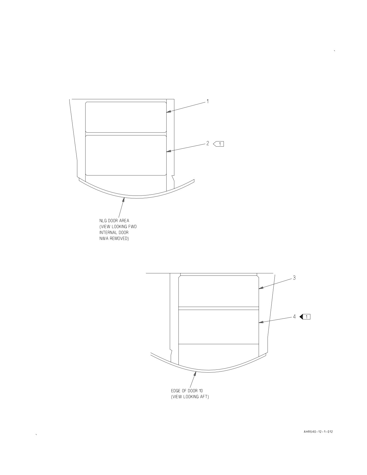
A1-AV8BC-410-100
008 00
Change 6
Page 9
Figure 1. Forward Avionics Cooling System Component Locator (Sheet 1)