F18. FLIGHT MANUAL (2008) - page 38
A1-F18EA-NFM-200
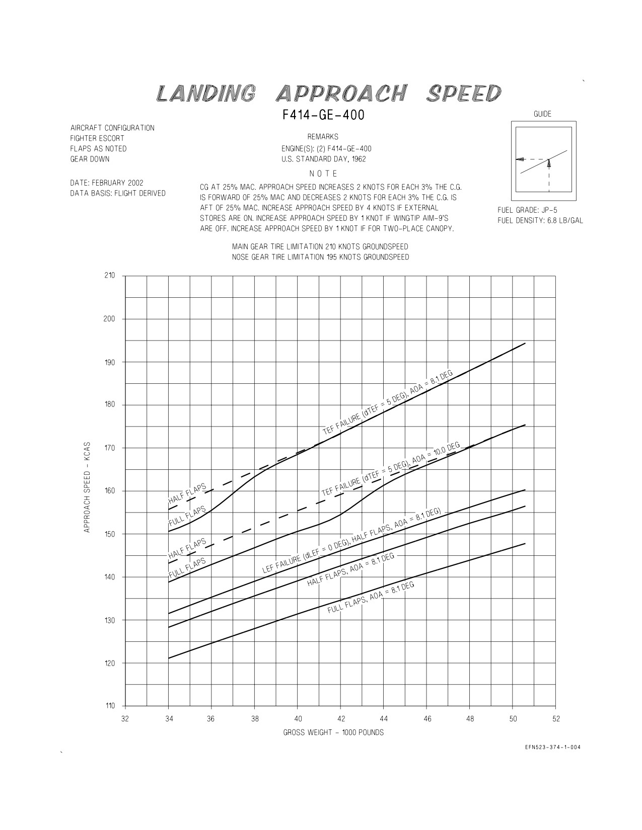
Figure 9-1. Landing Approach Speed
XI-9-4
ORIGINAL
A1-F18EA-NFM-200
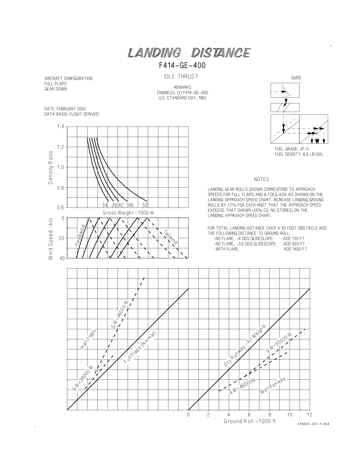
Figure 9-2. Landing Distance
XI-9-5
ORIGINAL
A1-F18EA-NFM-200
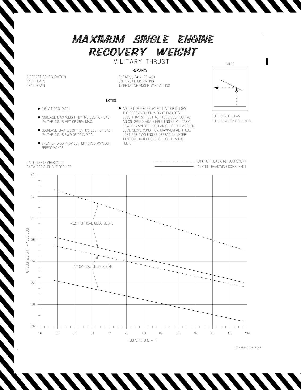
Figure 9-3. Maximum Single Engine Recovery Weight - Military Thrust
XI-9-6
CHANGE 3
A1-F18EA-NFM-200
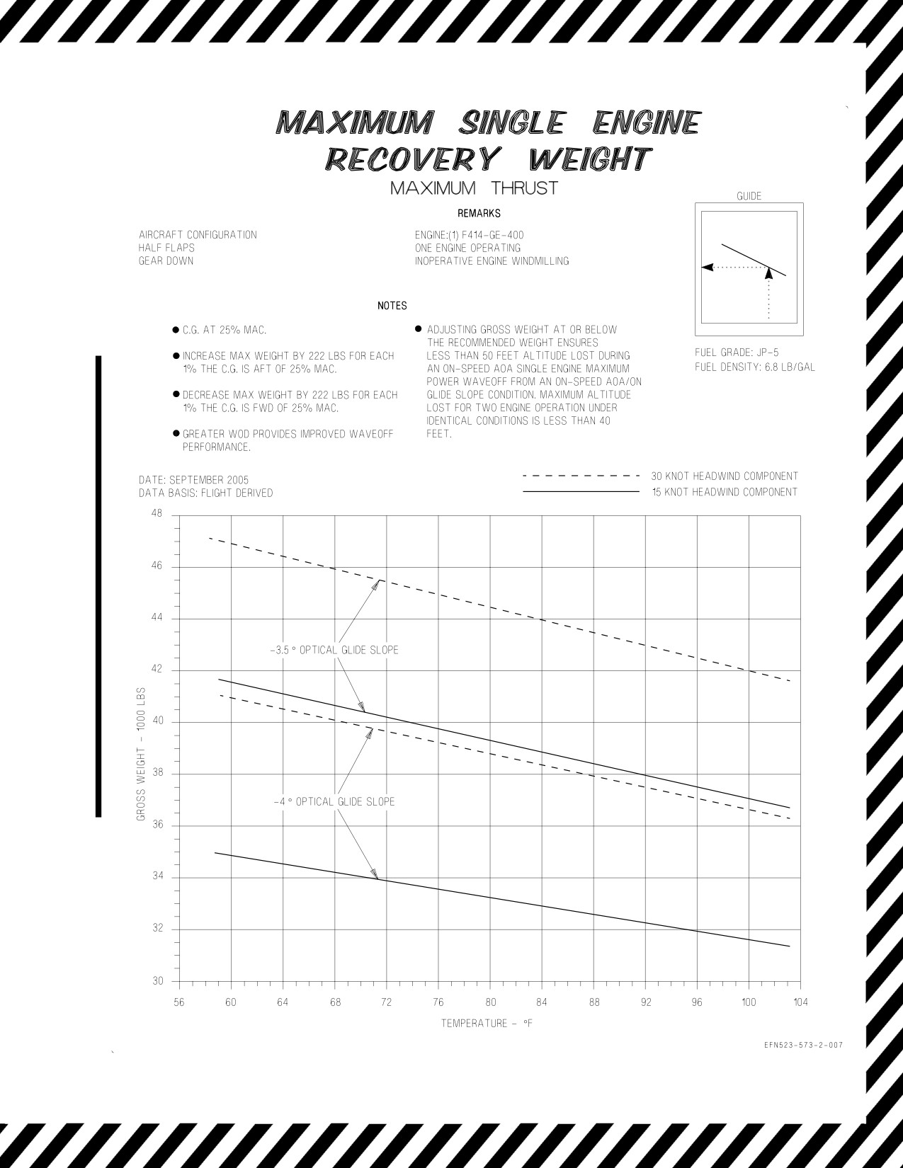
Figure 9-4. Maximum Single Engine Recovery Weight - Maximum Thrust
XI-9-7
(Reverse Blank)
CHANGE 3
A1-F18EA-NFM-200
CHAPTER 10
Mission Planning
F414-GE-400
10.1 TURN CAPABILITIES CHART
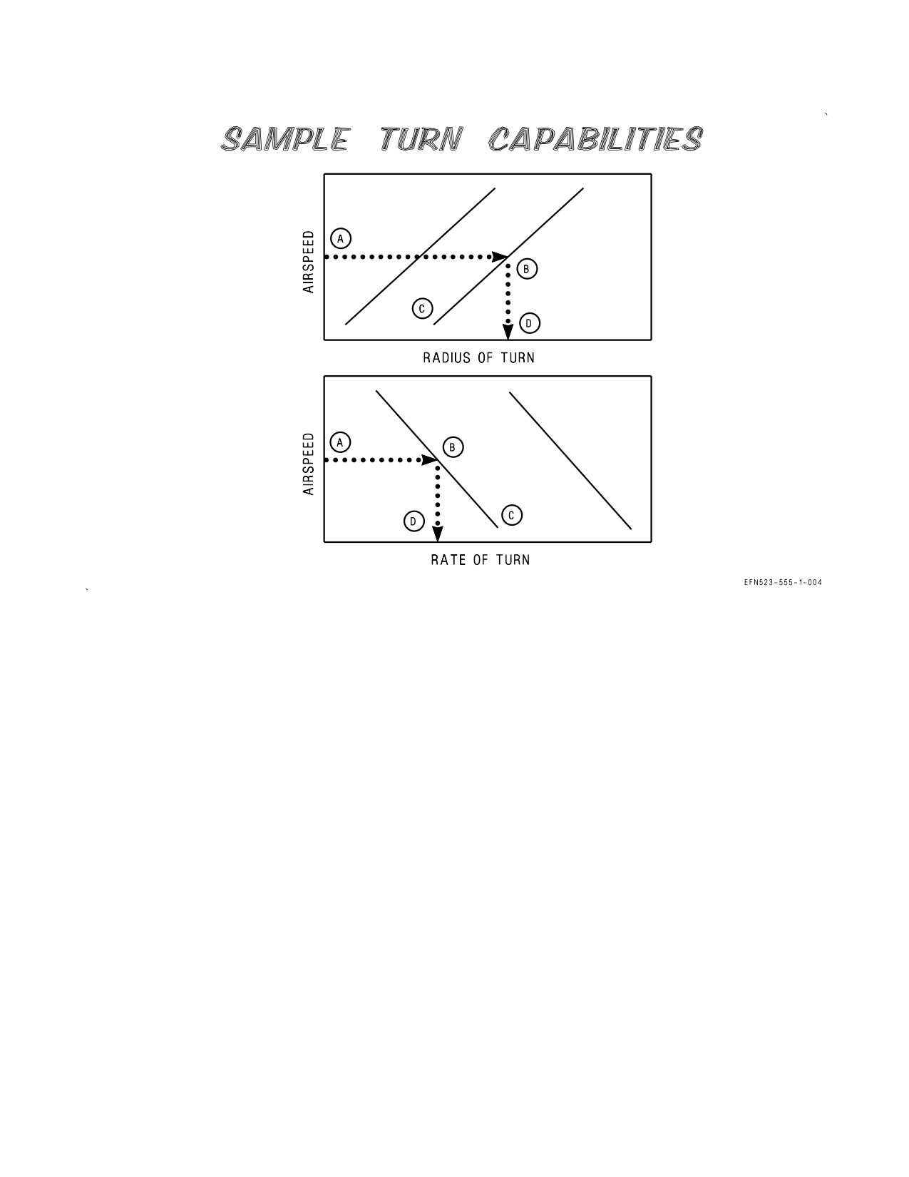
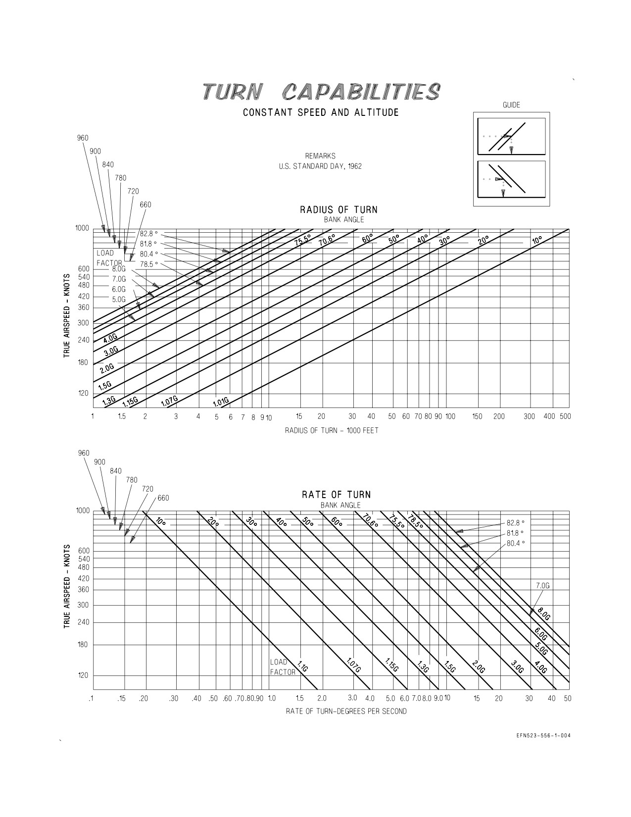
This chart (figure 10-1) presents the radius of turn and the rate of turn for a constant altitude,
constant speed turn. Turn data is available for various speeds and bank angles. Load factor is also
included for each bank angle.
10.1.1 Use. Enter the radius of turn plot with the true airspeed. Project horizontally right to the
desired bank angle. Note the load factor, then project vertically down and read the radius of turn.
Enter the rate of turn plot with the true airspeed. Project horizontally right to the bank angle, note the
load factor and then project down to read the rate of turn.
10.1.2 Sample Problem.
Radius of Turn
A. True airspeed
420 Kt.
B. Bank angle
60°
C. Load factor
2.0 G
D. Radius of Turn
9000 Ft.
Rate of Turn
A. True airspeed
420 Kt.
B. Bank angle
60°
C. Load factor
2.0 G
D. Rate of turn
4.5°/sec
XI-10-1
ORIGINAL
A1-F18EA-NFM-200
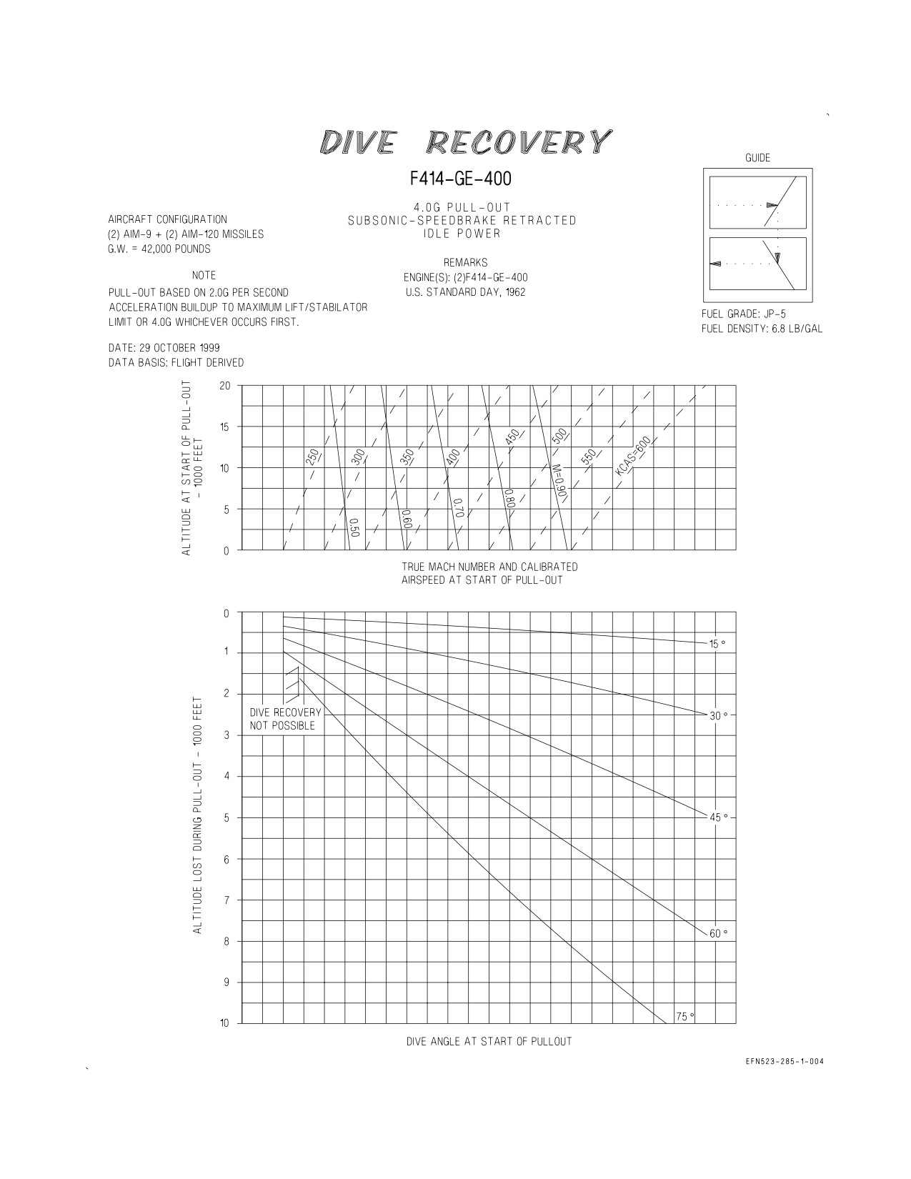
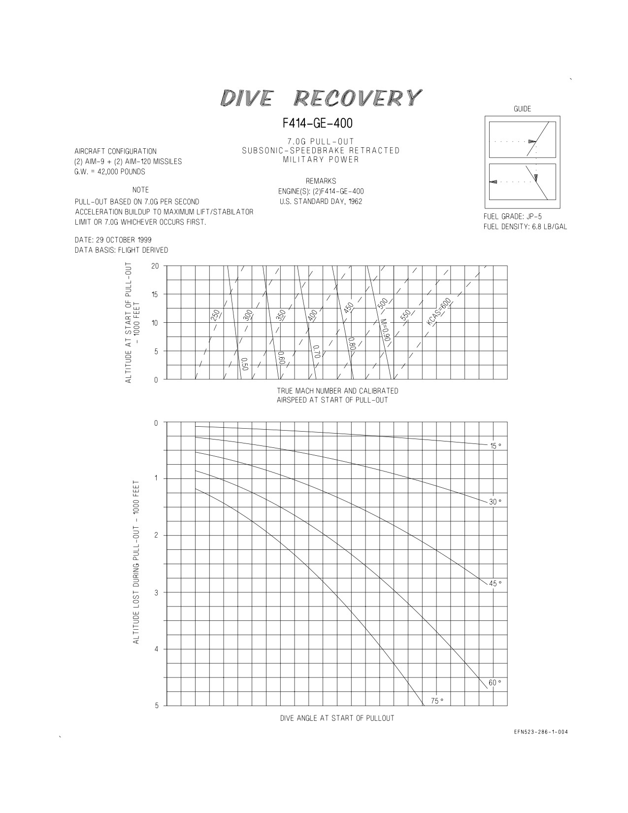
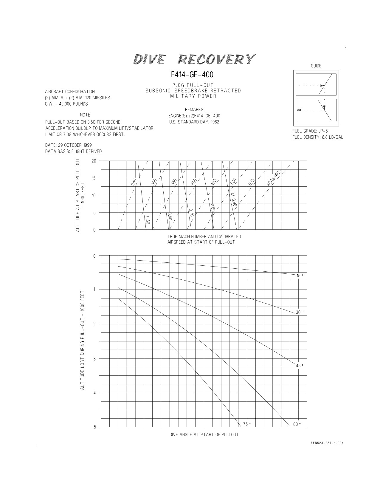
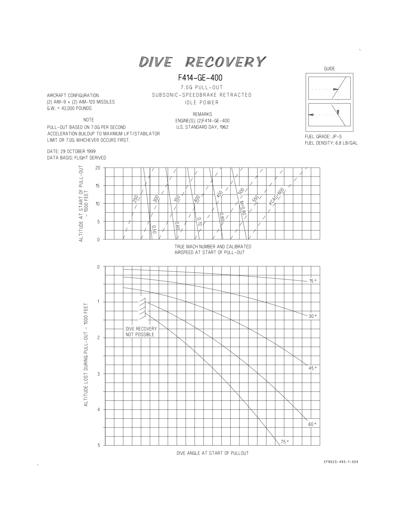
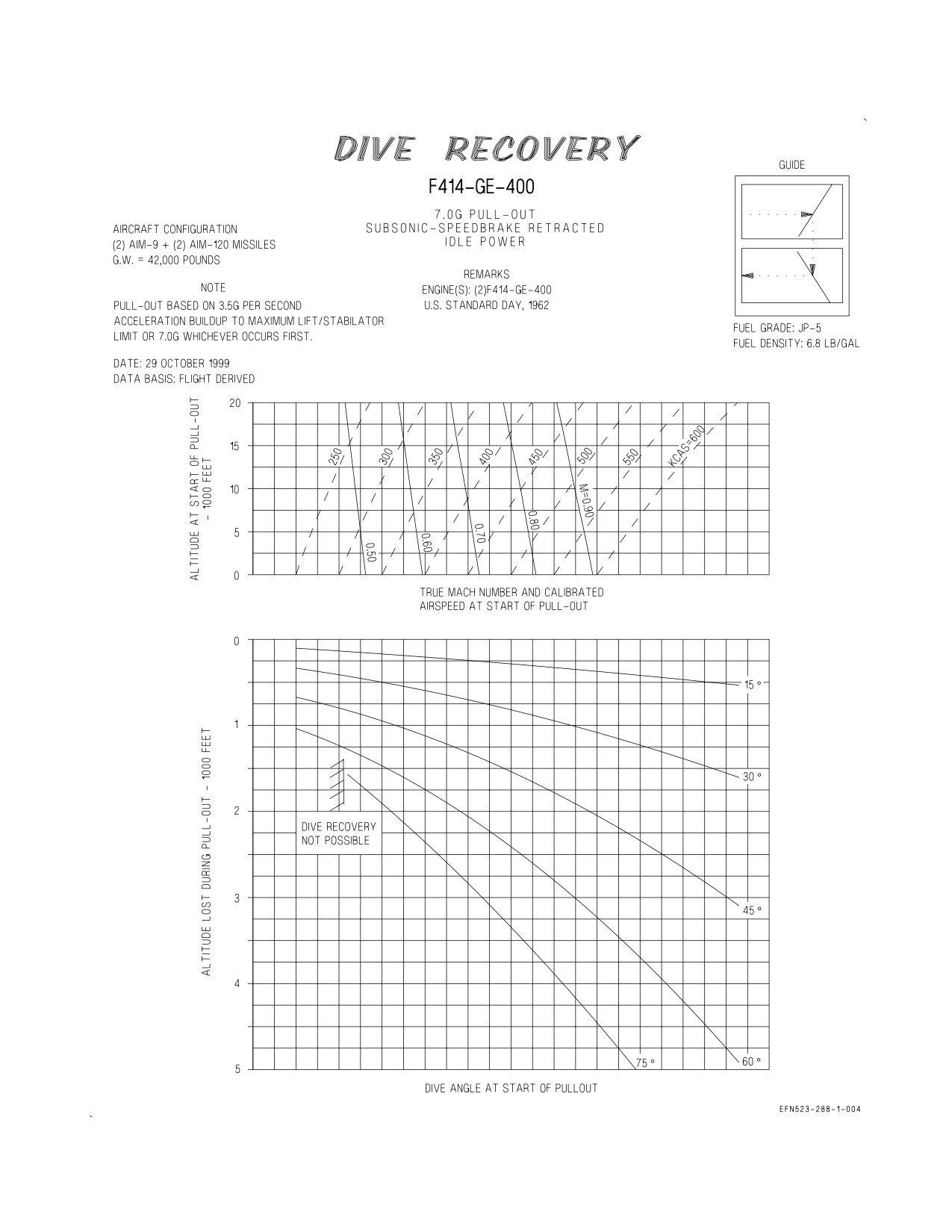
10.2 DIVE RECOVERY CHARTS
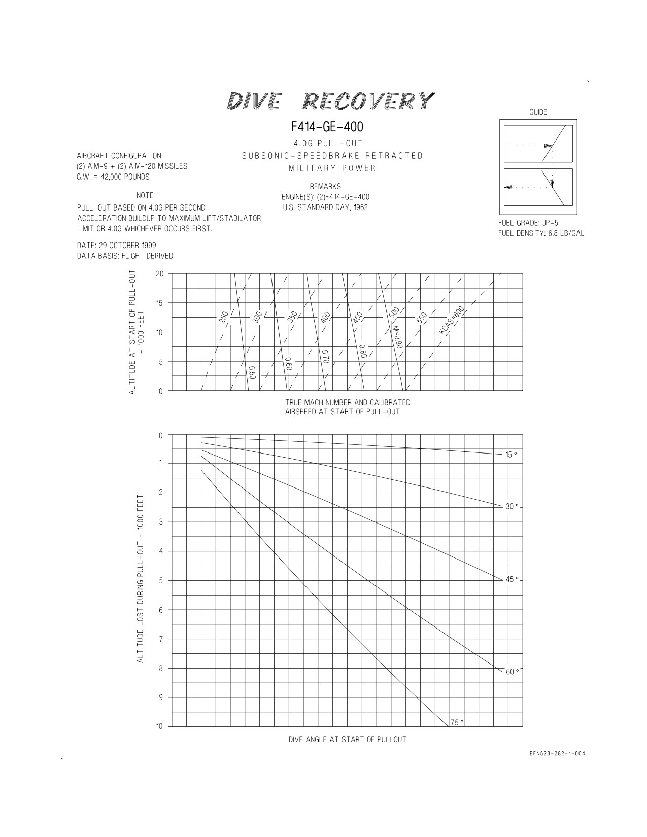
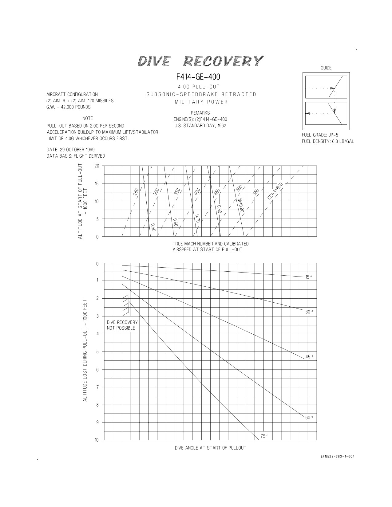
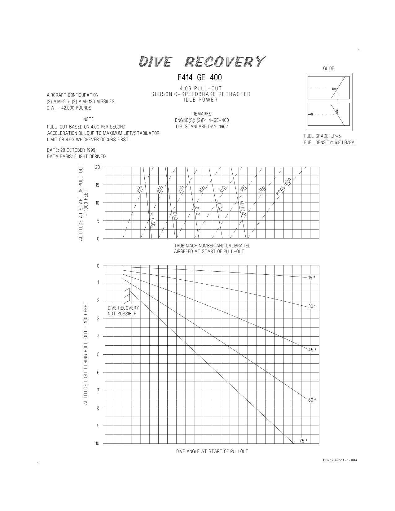
Subsonic dive recovery charts (figure 10-2) for two-engine operation are provided for the fighter
escort configuration ((2)AIM-9 + (2)AIM-120) at a gross weight of 42,000 pounds and with the
speedbrake retracted. Data is included for both military power and idle power settings. Two sets of dive
recovery data are presented. The first set of charts show pull-ups limited by maximum lift or 4.0G,
whichever occurs first, with entry rates of 4.0G and 2.0G per second. The second set of charts show
pull-ups limited by maximum lift or 7.0G, whichever occurs first, with entry rate of 7.0G and 3.5G per
second.
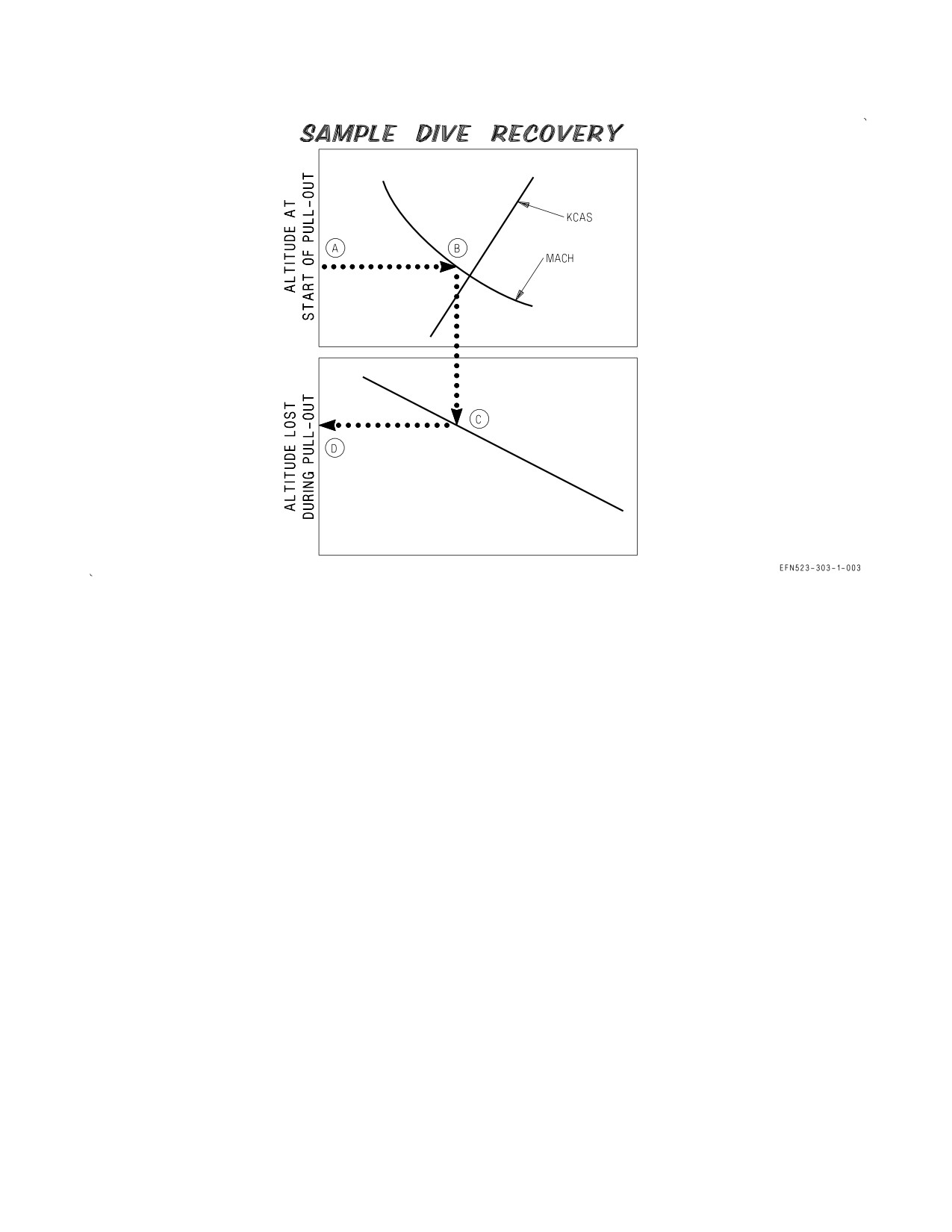
10.2.1 Use. Enter the chart with the altitude at the start of the pull-out and project horizontally right
to intersect true Mach number or calibrated airspeed at the start of the pull-out. From this point
project vertically down to intersect the dive angle at start of the pull-out then horizontally left to read
altitude lost during pull-out.
10.2.2 Sample Problem. Military Power, 4G, 4G per second.
A. Altitude at start of pull out
15,000 Ft.
B. Mach number at start of pull-out
0.70
C. Dive angle at start of pull-out
75°
D. Altitude lost during pull-out
5400 Ft.
XI-10-2
ORIGINAL
A1-F18EA-NFM-200
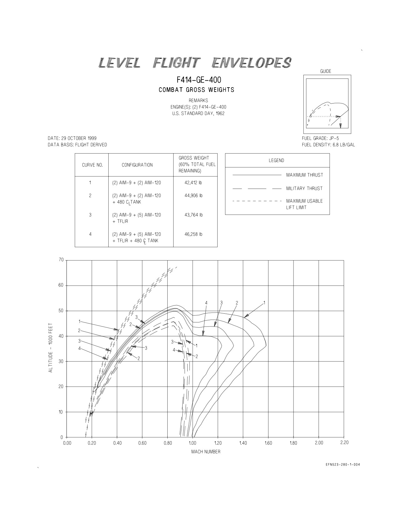
10.3 LEVEL FLIGHT ENVELOPES CHART
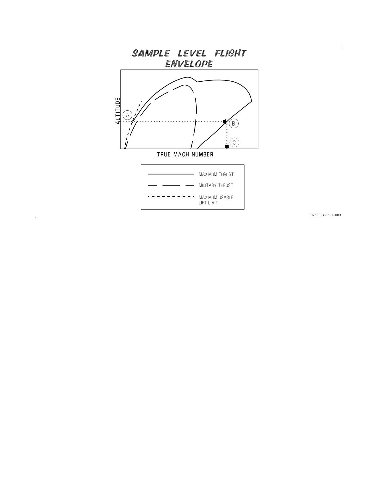
This chart (figure 10-3) presents the aircraft level flight speed envelope for various configurations at
combat gross weights equal to 60% total fuel. Parameters of the envelopes extend from the lift limit
to Vmax throughout the altitude range. Both maximum and military thrust flight envelopes are present.
10.3.1 Use. Enter the appropriate chart with the desired combat altitude. Project horizontally right
to intersect the applicable configuration power curve. From this point, project vertically down to read
the maximum attainable Mach number in level flight.
10.3.2 Sample Problem.
A. Combat Altitude
36,000 Ft.
B. Configuration Line:
(2) AIM-9 + (2) AIM-120
C. Maximum attainable Mach number
1.590
XI-10-3
ORIGINAL
A1-F18EA-NFM-200
10.4 LOW ALTITUDE ACCELERATION CHARTS
These charts (figures 10-4 and 10-5) present time and fuel required to accelerate from 360 KIAS to
desired KIAS up thru 550 KIAS at altitudes of sea level, 2,000, 4,000, and 6,000 feet. Separate charts
are provided for both maximum and military thrust for gross weights of 34,000, 38,000, 42,000, 46,000,
and 50,000 pounds. The time and fuel values are calculated for U.S. Standard Day conditions; however,
correction factors are given for nonstandard temperatures.
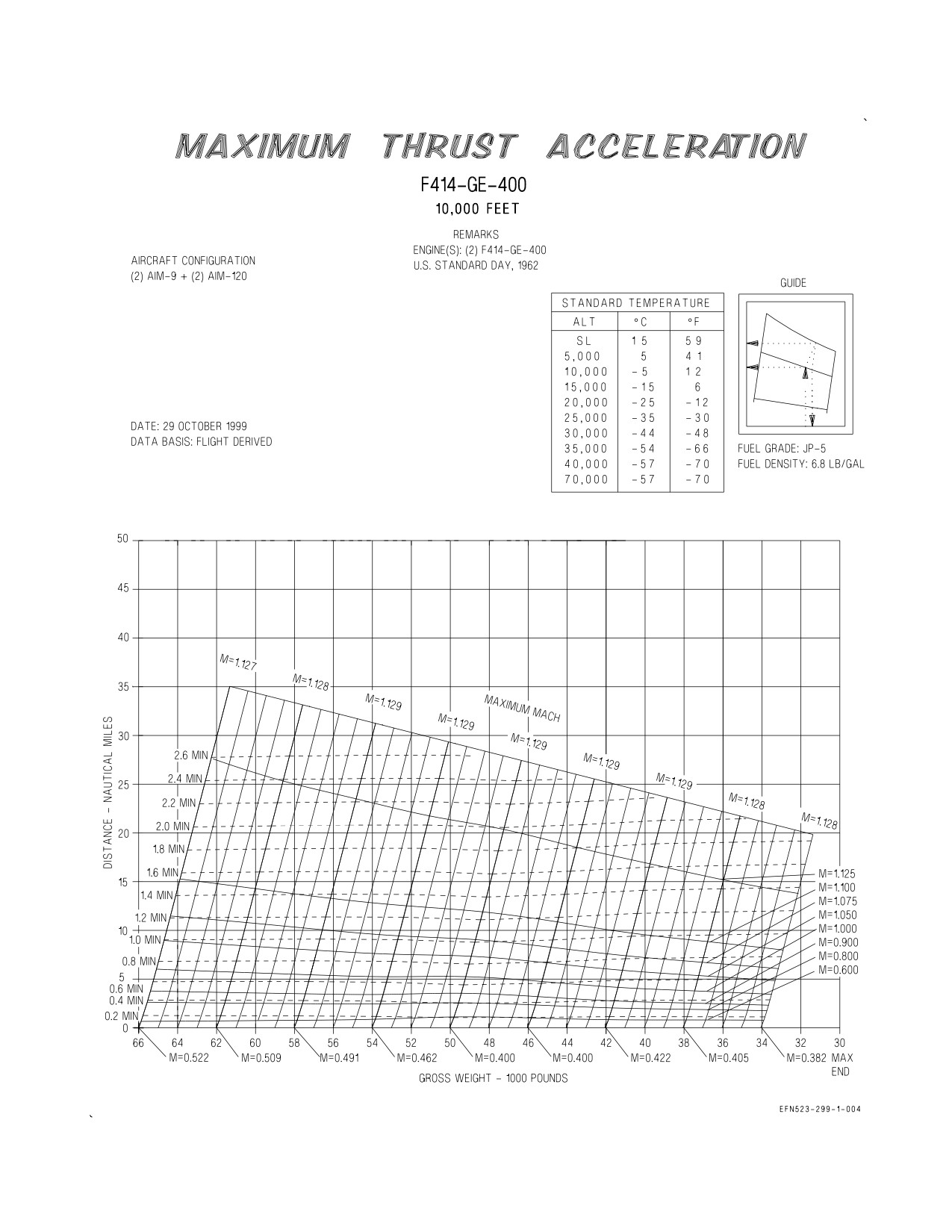
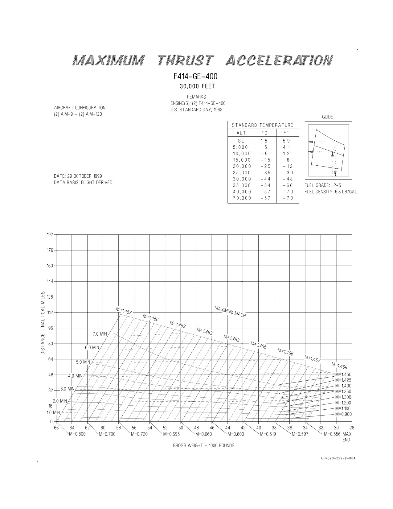
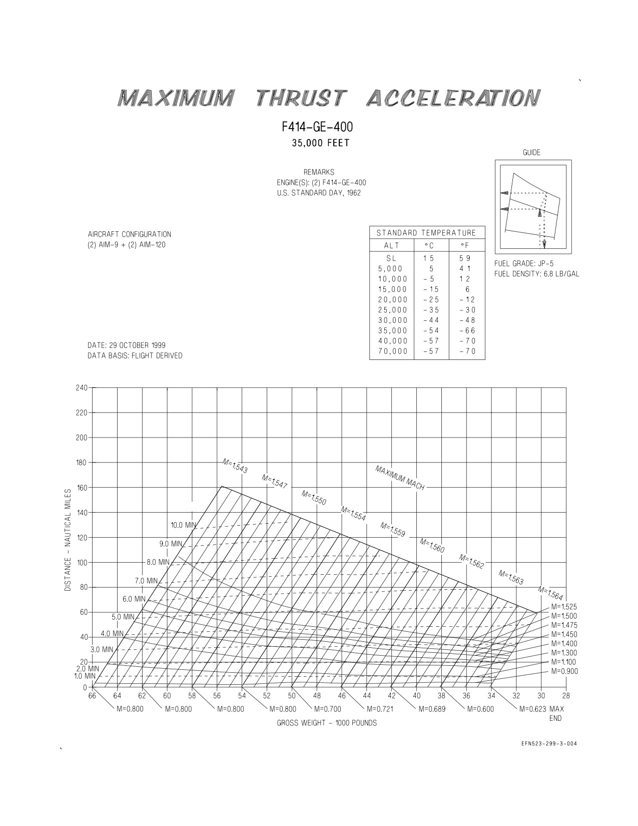
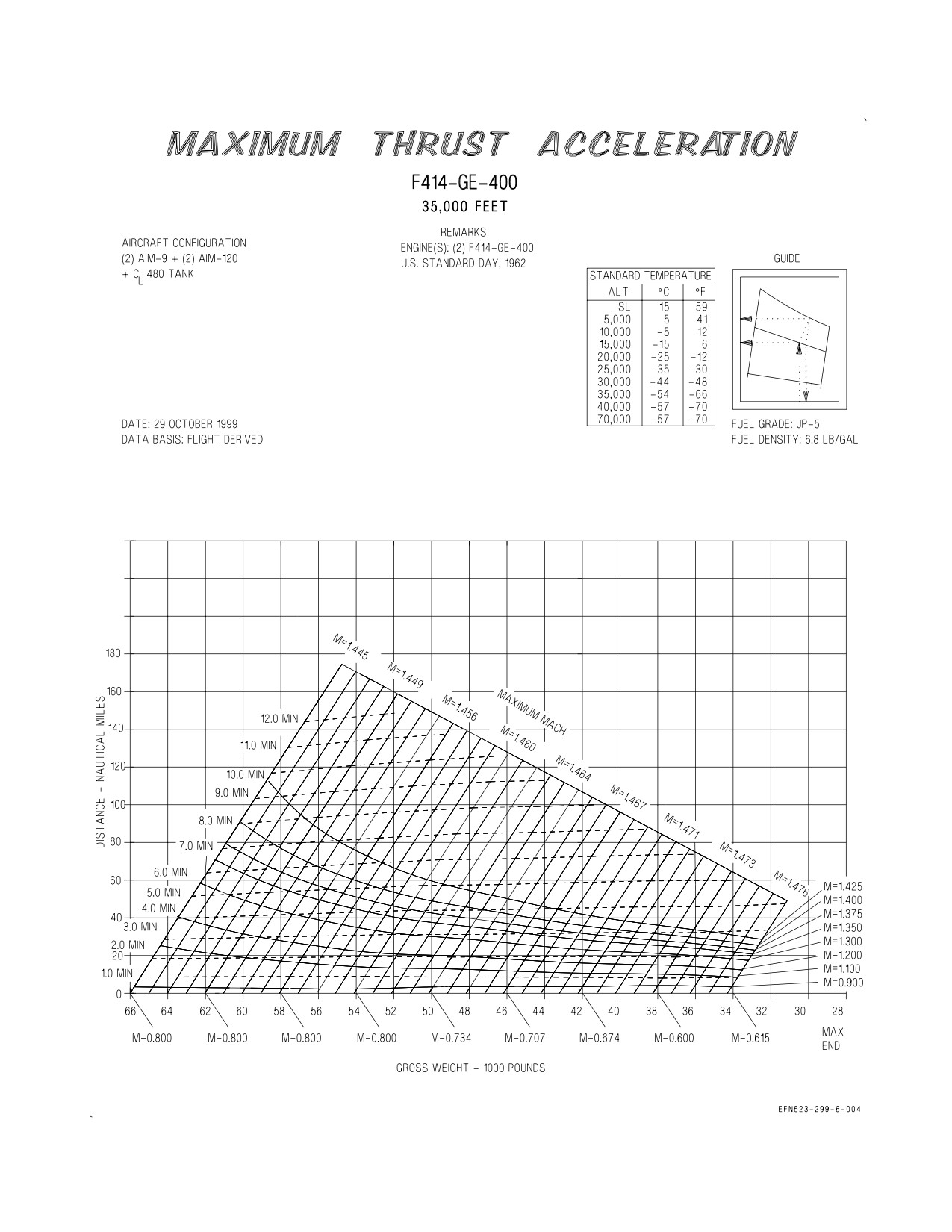
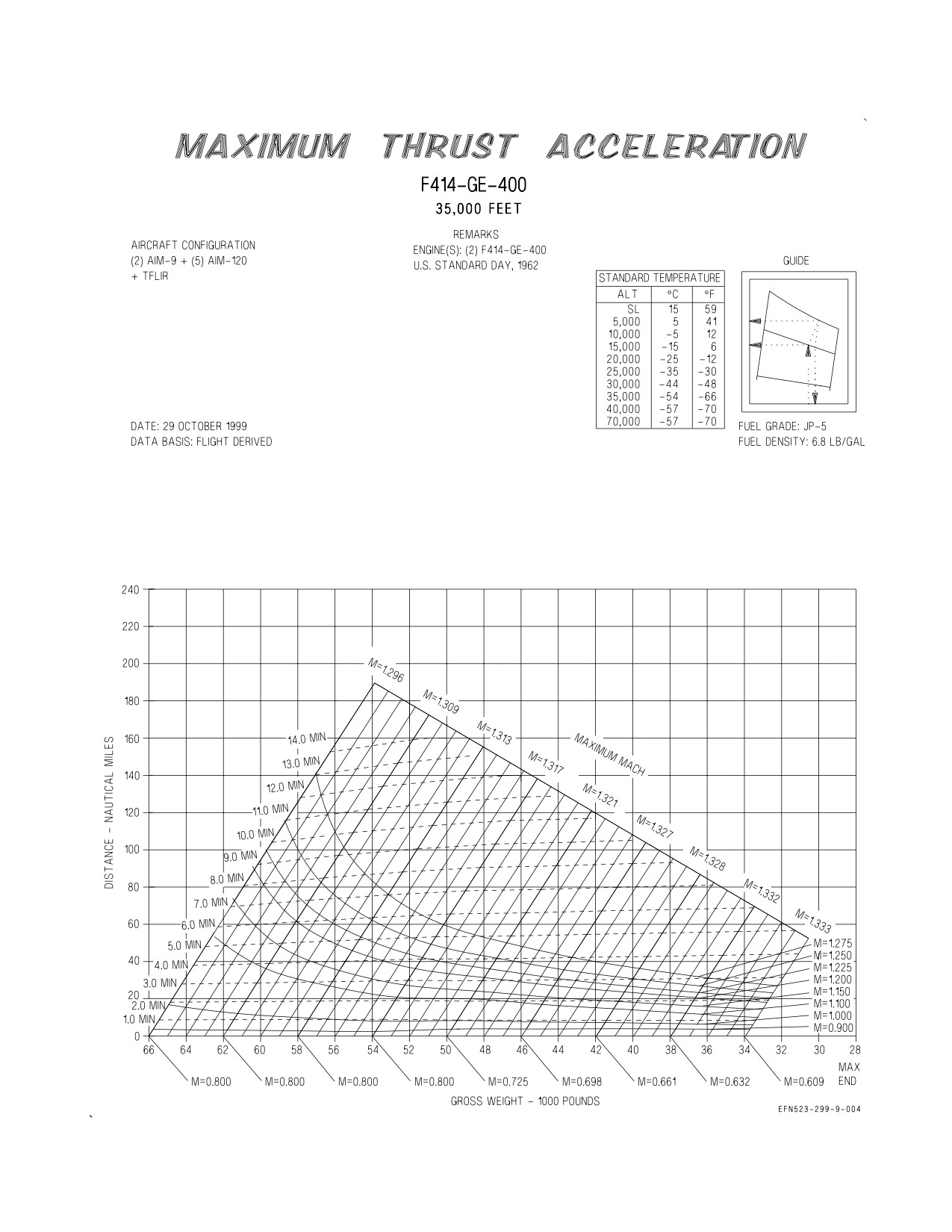
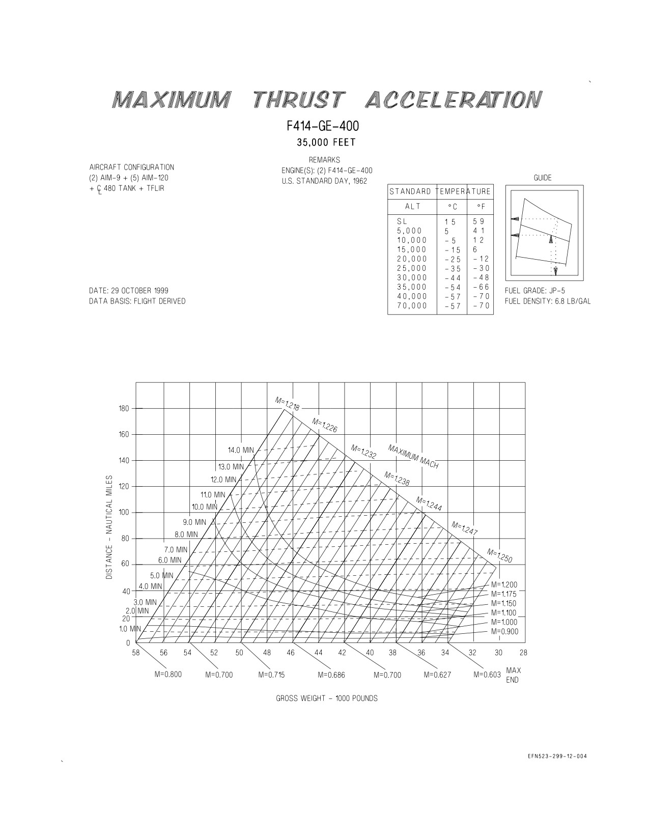
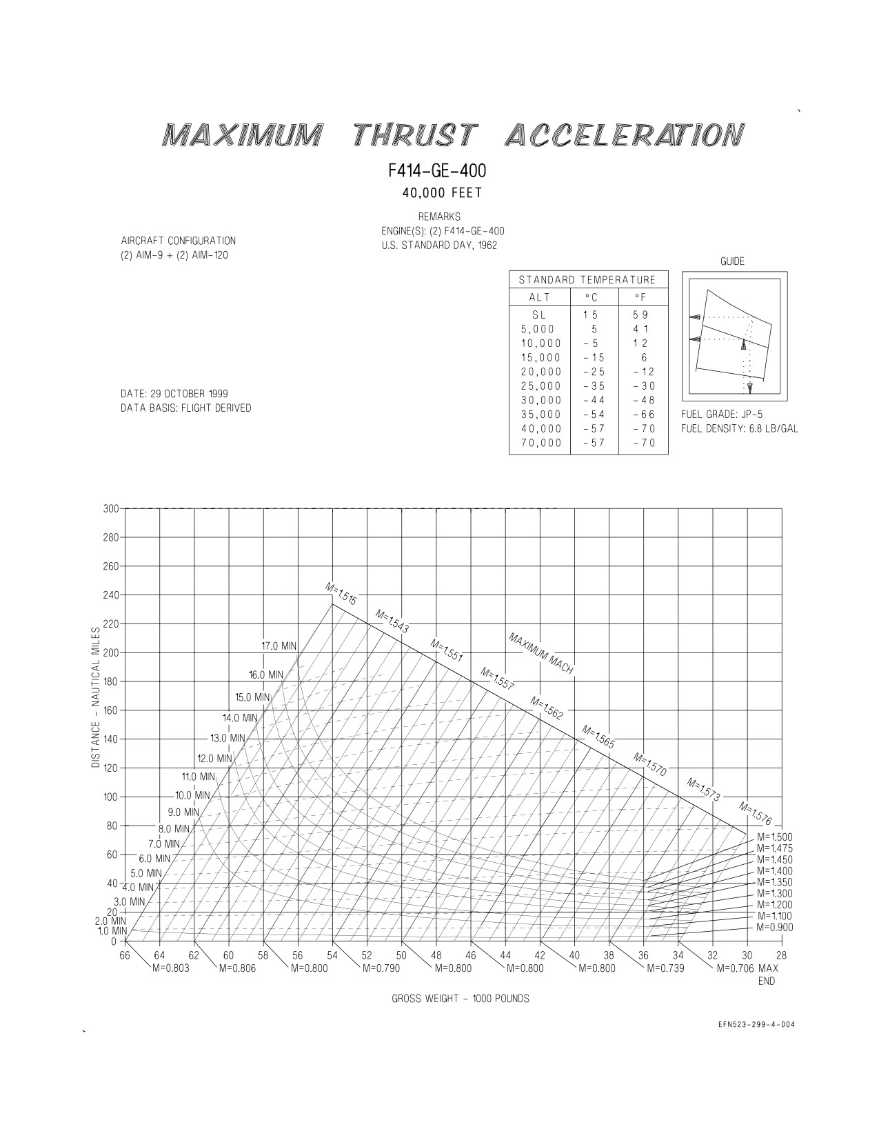
10.5 MAXIMUM THRUST ACCELERATION CHARTS
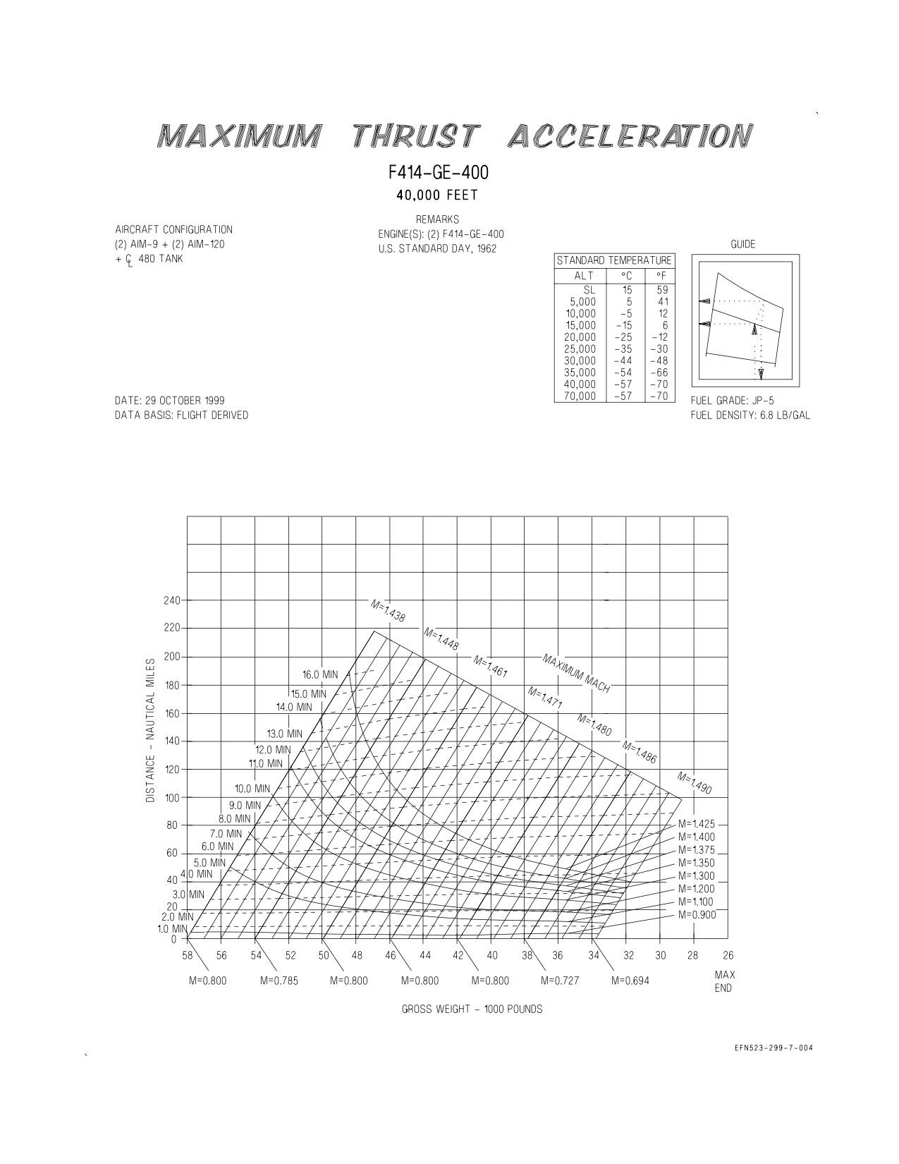
These charts (figures 10-6 thru 10-9) show the relationship of time, distance, and fuel required for
level flight, maximum thrust accelerations. The Maximum Endurance Mach number (MAX END) for
a given gross weight is provided across the bottom of the charts. This data is presented for various
altitudes and configurations.
XI-10-4
ORIGINAL
A1-F18EA-NFM-200
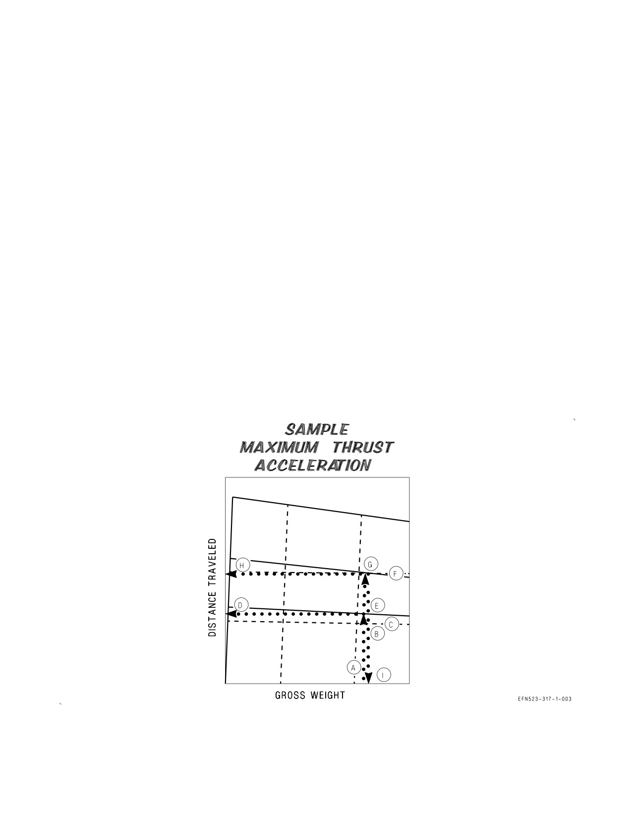
10.5.1 Use. Enter the applicable chart with the aircraft gross weight. Project vertically up to the
initial Mach number. From this point, project both horizontally to the left and note time and distance;
and up parallel to the vertical guide lines to the Mach number desired at the end of the acceleration.
From this point, project horizontally to the left and note the time and distance; and vertically
downwards and note gross weight. Subtract the time, distance, and gross weight corresponding to the
initial Mach number from the time, distance and gross weight corresponding to the desired Mach
number to determine the time, distance, and fuel required for acceleration.
10.5.2 Sample Problem. Configuration - (2) AIM-9 + (2) AIM-120
10,000 Feet
A. Gross weight
48,000 Lb.
B. Initial Mach number
0.8
C. Time
0.4 Min.
D. Distance
2.5 NM
E. Parallel guidelines
F. Desired Mach number
1.0
G. Time corresponding to new Mach number
0 .62 Min.
H. Distance corresponding to new Mach number
5.0 NM
I. Gross weight corresponding to new Mach number
47,700 Lb.
J. Time required for acceleration (G-C)
0.22 Min.
K. Distance required for acceleration (H-D)
2.5 NM
L. Fuel required for acceleration (A-I)
300 Lb.
XI-10-5
ORIGINAL
A1-F18EA-NFM-200
Figure 10-1. Turn Capabilities
XI-10-6
ORIGINAL
A1-F18EA-NFM-200
Figure 10-2. Dive Recovery (Sheet 1 of 8)
XI-10-7
ORIGINAL
A1-F18EA-NFM-200
Figure 10-2. Dive Recovery (Sheet 2 of 8)
XI-10-8
ORIGINAL
A1-F18EA-NFM-200
Figure 10-2. Dive Recovery (Sheet 3 of 8)
XI-10-9
ORIGINAL
A1-F18EA-NFM-200
Figure 10-2. Dive Recovery (Sheet 4 of 8)
XI-10-10
ORIGINAL
A1-F18EA-NFM-200
Figure 10-2. Dive Recovery (Sheet 5 of 8)
XI-10-11
ORIGINAL
A1-F18EA-NFM-200
Figure 10-2. Dive Recovery (Sheet 6 of 8)
XI-10-12
ORIGINAL
A1-F18EA-NFM-200
Figure 10-2. Dive Recovery (Sheet 7 of 8)
XI-10-13
ORIGINAL
A1-F18EA-NFM-200
Figure 10-2. Dive Recovery (Sheet 8 of 8)
XI-10-14
ORIGINAL
A1-F18EA-NFM-200
Figure 10-3. Level Flight Envelopes
XI-10-15
ORIGINAL
A1-F18EA-NFM-200
Figure 10-6. Maximum Thrust Acceleration - 10,000 Feet
XI-10-26
ORIGINAL
A1-F18EA-NFM-200
Figure 10-7. Maximum Thrust Acceleration - 30,000 Feet (Sheet 1 of 4)
XI-10-27
ORIGINAL
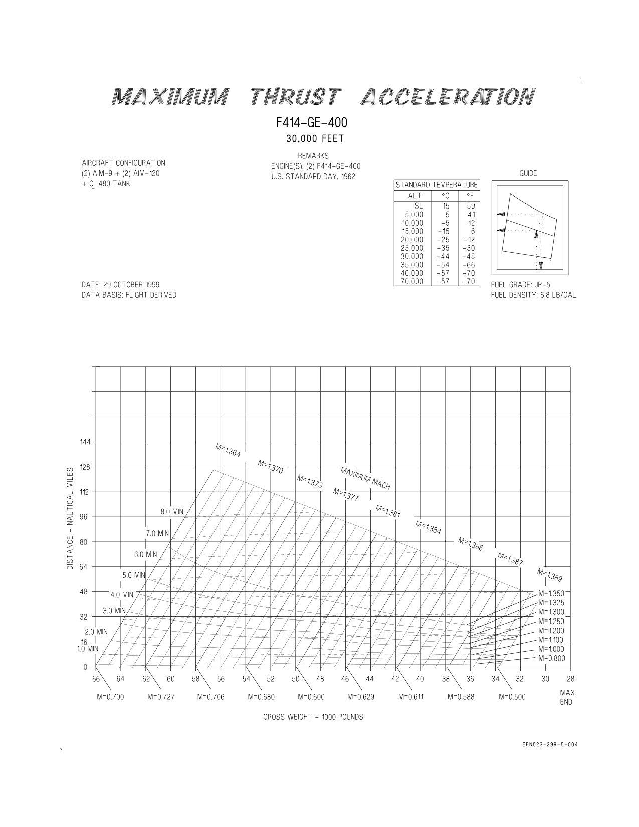
A1-F18EA-NFM-200
Figure 10-7. Maximum Thrust Acceleration - 30,000 Feet (Sheet 2 of 4)
XI-10-28
ORIGINAL
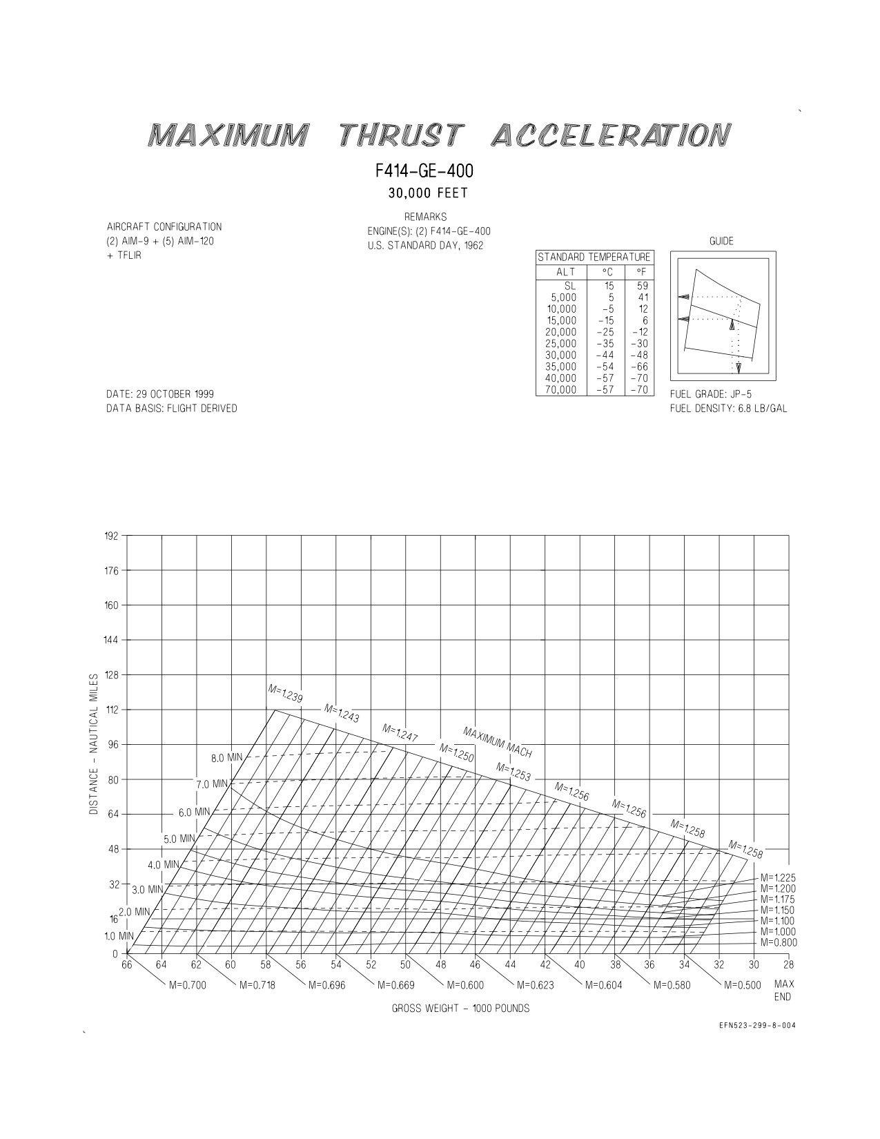
A1-F18EA-NFM-200
Figure 10-7. Maximum Thrust Acceleration - 30,000 Feet (Sheet 3 of 4)
XI-10-29
ORIGINAL
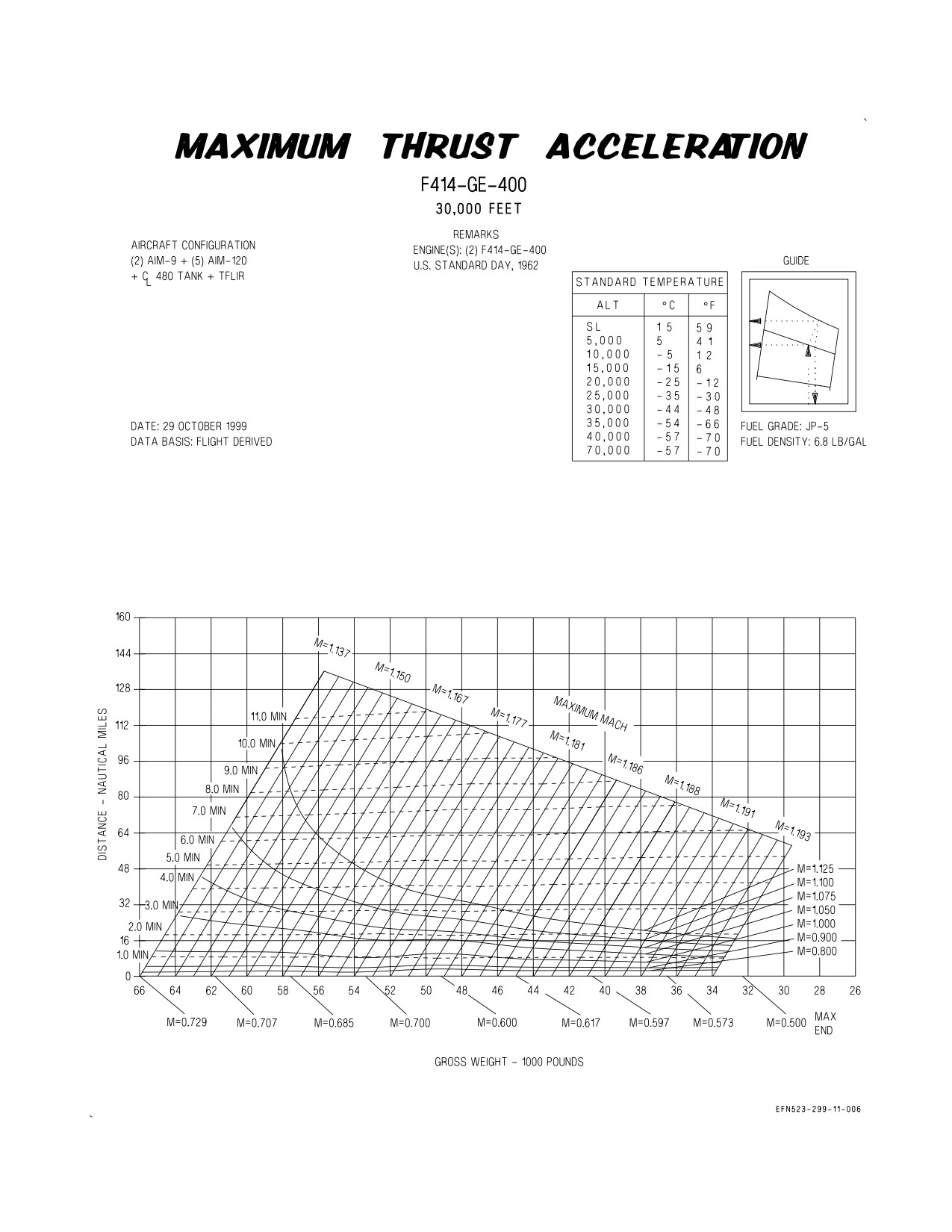
A1-F18EA-NFM-200
Figure 10-7. Maximum Thrust Acceleration - 30,000 Feet (Sheet 4 of 4)
XI-10-30
CHANGE 2
A1-F18EA-NFM-200
Figure 10-8. Maximum Thrust Acceleration - 35,000 Feet (Sheet 1 of 4)
XI-10-31
ORIGINAL
A1-F18EA-NFM-200
Figure 10-8. Maximum Thrust Acceleration - 35,000 Feet (Sheet 2 of 4)
XI-10-32
ORIGINAL
A1-F18EA-NFM-200
Figure 10-8. Maximum Thrust Acceleration - 35,000 Feet (Sheet 3 of 4)
XI-10-33
ORIGINAL
A1-F18EA-NFM-200
Figure 10-8. Maximum Thrust Acceleration - 35,000 Feet (Sheet 4 of 4)
XI-10-34
ORIGINAL
A1-F18EA-NFM-200
Figure 10-9. Maximum Thrust Acceleration - 40,000 Feet (Sheet 1 of 2)
XI-10-35
ORIGINAL
A1-F18EA-NFM-200
Figure 10-9. Maximum Thrust Acceleration - 40,000 Feet (Sheet 2 of 2)
XI-10-36
ORIGINAL
A1-F18EA-NFM-200
ALPHABETICAL INDEX
Page
No.
A
ADJUSTMENT TO SEROC FOR RETRACTING LANDING GEAR CHART
XI-4-11
Sample Problems
XI-4-11
Use
XI-4-11
AIRSPEED CONVERSION CHART
XI-2-3
AIRSPEED POSITION ERROR CORRECTION CHARTS
XI-2-3
Sample Problem
XI-2-3
ALTIMETER POSITION ERROR CORRECTION CHARTS
XI-2-4
Sample Problem
XI-2-4
Use
XI-2-4
ANGLE OF ATTACK CONVERSION CHART
XI-2-6
Sample Problem
XI-2-6
Use
XI-2-6
B
BINGO CHARTS
XI-5-9
C
CLIMB CHARTS - 350 KCAS
XI-4-4
Sample Problem
XI-4-5
Use
XI-4-4
CLIMB PERFORMANCE CHARTS
XI-4-1
Maximum Thrust Climb
XI-4-1
Military Thrust Climb
XI-4-1
Sample Problem
XI-4-2
Use
XI-4-1
COMBAT FUEL FLOW CHARTS
XI-5-4
Sample Problem
XI-5-5
Use
XI-5-5
COMBAT SPECIFIC RANGE CHARTS
XI-5-4
Sample Problem
XI-5-4
Use
XI-5-4
CONSTANT ALTITUDE/LONG RANGE CRUISE (SPEED-TIME-FUEL) CHART
XI-5-6
Sample Problem
XI-5-7
Use
XI-5-6
CONSTANT ALTITUDE/LONG RANGE CRUISE (TRUE AIRSPEED AND FUEL FLOW)
CHART
XI-5-8
Sample Problem
XI-5-8
Use
XI-5-8
Index-1
ORIGINAL
A1-F18EA-NFM-200
Page
No.
D
DENSITY RATIO CHART
XI-3-2
Sample Problem
XI-3-2
Use
XI-3-2
DIVE RECOVERY CHARTS
XI-10-2
Sample Problem
XI-10-2
Use
XI-10-2
DRAG INDEX SYSTEM
XI-2-1
Determining Interference Drag
XI-2-1
Sample Problem
XI-2-2
Determining the Basic Store Drag
XI-2-1
Sample Problem
XI-2-1
F
F/A-18E TANKER RECEIVER ENVELOPE
XI-7-1
Sample Problem
XI-7-1
Use
XI-7-1
G
GLOSSARY OF TERMS
XI-1-1
Calibrated Airspeed
XI-1-1
Combat Ceiling
XI-1-1
Density Altitude
XI-1-1
Density Ratio
XI-1-1
Equivalent Airspeed
XI-1-1
Indicated Airspeed
XI-1-1
Nosewheel Lift-Off Speed
XI-1-1
Pressure Altitude
XI-1-1
Takeoff Speed
XI-1-1
True Airspeed
XI-1-1
I
INSTANTANEOUS RATE OF CLIMB CHARTS
XI-4-6
Sample Problem
XI-4-7
Use
XI-4-6
INTRODUCTION
XI-1-1
L
LANDING APPROACH SPEED CHART
XI-9-1
Sample Problem
XI-9-1
Use
XI-9-1
LANDING DISTANCE CHART
XI-9-1
Sample Problem
XI-9-2
Use
XI-9-1
LEVEL FLIGHT ENVELOPES CHART
XI-10-3
Index-2
ORIGINAL
A1-F18EA-NFM-200
Page
No.
Sample Problem
XI-10-3
Use
XI-10-3
LOW ALTITUDE ACCELERATION CHARTS
XI-10-4
M
MAXIMUM ABORT SPEED CHARTS
XI-3-5
Sample Problem
XI-3-5
Use
XI-3-5
MAXIMUM ENDURANCE CHARTS
XI-6-1
Sample Problem
XI-6-1, XI-6-2, XI-6-4
Use
XI-6-1
MAXIMUM GROSS WEIGHT WITH SINGLE ENGINE CHARTS
XI-3-4
Sample Problem
XI-3-4
Use
XI-3-4
MAXIMUM RANGE AOA/MAXIMUM ENDURANCE AOA CHART
XI-5-9, XI-5-192, XI-6-4
MAXIMUM RANGE DESCENT CHARTS
XI-8-3
Use
XI-8-3
Descent Speed
XI-8-3
Sample Problem
XI-8-3
Time, Fuel, and Distance Required
XI-8-3
Sample Problem
XI-8-4
MAXIMUM SINGLE ENGINE RECOVERY WEIGHT CHART
XI-9-3
Sample Problem
XI-9-3
Use
XI-9-3
MAXIMUM THRUST ACCELERATION CHARTS
XI-10-4
Sample Problem
XI-10-5
Use
XI-10-5
MINIMUM GO SPEED CHARTS
XI-3-2
Sample Problem
XI-3-3
Use
XI-3-2
N
NORMAL DESCENT CHARTS
XI-8-1
Sample Problem
XI-8-1, XI-8-2
Use
XI-8-1
O
OPTIMUM CRUISE CHARTS
XI-5-1
Sample Problem
XI-5-2
Use
XI-5-1
P
PEAK RATE OF CLIMB CHARTS
XI-4-6
Use
XI-4-6
Index-3
ORIGINAL
A1-F18EA-NFM-200
Page
No.
S
SINGLE ENGINE RATE OF CLIMB TAKEOFF CONFIGURATION CHARTS
XI-4-9
Sample Problems
XI-4-10
Use
XI-4-9
SPECIFIC RANGE CHARTS
XI-5-2
Sample Problem
XI-5-3
Use
XI-5-2
STALL SPEEDS CHART
XI-2-5
Sample Problem
XI-2-5
Use
XI-2-5
SUPERSONIC MAXIMUM THRUST CLIMB CHARTS
XI-4-8
Sample Problem
XI-4-8
Use
XI-4-8
T
TAKEOFF ALLOWANCES CHART
XI-4-1
TAKEOFF DISTANCE CHARTS
XI-3-6
Sample Problem
XI-3-7
Use
XI-3-6
TAKEOFF GROUND ROLL CORRECTION FOR CG CHARTS
XI-3-8
Sample Problem
XI-3-9
Use
XI-3-8
TURN CAPABILITIES CHART
XI-10-1
Sample Problem
XI-10-1
Use
XI-10-1
W
WIND COMPONENTS CHART
XI-3-1
Sample Problem
XI-3-1
Use
XI-3-1
Index-4
ORIGINAL
A1-F18EA-NFM-200
LIST OF EFFECTIVE PAGES
Effective Pages
Page Numbers
Effective Pages
Page Numbers
CHANGE 3
1
(Reverse Blank)
ORIGINAL
XI-4-49 (Reverse Blank)
ORIGINAL
3
(Reverse Blank)
ORIGINAL
XI-5-1
ORIGINAL
5 Thru 14
CHANGE 1
XI-5-2
CHANGE 3
15
(Reverse Blank)
ORIGINAL
XI-5-3
ORIGINAL
17
(Reverse Blank)
CHANGE 1
XI-5-4
CHANGE 3
19
(Reverse Blank)
ORIGINAL
XI-5-5
ORIGINAL
21
(Reverse Blank)
CHANGE 1
XI-5-6
ORIGINAL
23 Thru 27 (Reverse
ORIGINAL
XI-5-7
Blank)
CHANGE 1
XI-5-8 Thru XI-5-9
ORIGINAL
29
(Reverse Blank)
ORIGINAL
XI-5-10 Thru XI-5-180
ORIGINAL
XI-1-1 (Reverse Blank)
CHANGE 1
XI-5-181 Thru XI-5-187
ORIGINAL
XI-2-1 Thru XI-2-29
ORIGINAL
XI-5-188 Thru XI-5-192
(Reverse Blank)
ORIGINAL
XI-6-1 Thru XI-6-11
CHANGE 2
XI-3-1
(Reverse Blank)
ORIGINAL
XI-3-2 Thru XI-3-19
ORIGINAL
XI-7-1 Thru XI-7-2
(Reverse Blank)
ORIGINAL
XI-8-1 Thru XI-8-13
ORIGINAL
XI-4-1 Thru XI-4-15
CHANGE 2
XI-8-14
CHANGE 2
XI-4-16 Thru XI-4-18
ORIGINAL
XI-8-15 Thru XI-8-20
ORIGINAL
XI-4-19 Thru XI-4-21
ORIGINAL
XI-9-1 Thru XI-9-2
CHANGE 2
XI-4-22 Thru XI-4-27
CHANGE 3
XI-9-3
ORIGINAL
XI-4-28
ORIGINAL
XI-9-4 Thru XI-9-5
CHANGE 2
XI-4-29 Thru XI-4-31
CHANGE 3
XI-9-6 Thru XI-9-7
ORIGINAL
XI-4-32 Thru XI-4-33
(Reverse Blank)
CHANGE 2
XI-4-34 Thru XI-4-36
ORIGINAL
XI-10-1 Thru XI-10-29
ORIGINAL
XI-4-37 Thru XI-4-42
CHANGE 2
XI-10-30
CHANGE 1
XI-4-43 Thru XI-4-45
ORIGINAL
XI-10-31 Thru XI-10-36
CHANGE 3
XI-4-46 Thru XI-4-47
ORIGINAL
Index-1 Thru Index-4
CHANGE 2
XI-4-48
CHANGE 3
LEP-1 (Reverse Blank)
LEP-1 (Reverse Blank)
CHANGE 3