F18. FLIGHT MANUAL (2008) - page 31
A1-F18EA-NFM-000
135. If the velocity vector begins to flash slowly but is not HUD limited:
a. Selected ordnance has been released.
b. The mission computer may be displaying a degraded velocity vector
c. The waterline symbol is HUD limited
d. STBY attitude indicator is providing HUD attitude information
136. The HUD landing display (elongated horizon bar, AOA bracket, waterline symbol, steering
display) will be presented:
a. When selected through the HUD control panel
b. When selected on the right DDI
c. When gear is down and NAV master mode is selected
d. Any time that the gear is down
137. True/False: While using NAV master mode, the flight crewmember has the option to cage or
uncage the velocity vector on the HUD.
138. At what altitude will the cockpit begin to pressurize?
139. What action should be taken if FCS HOT caution light comes on in flight?
a.
b.
140. When the G XMT switch is placed to COMM 1 or COMM 2 the:
a. Selected radio will receive/transmit on 243.0 only
b. Selected radio will receive only 243.0
c. Selected radio will transmit only 243.0
141. The hydraulic pumps are located on the
and maintain the hydraulic pressure at
approximately
psi.
142. The HYD 2 priority valves close at approximately
psi.
143. Placing the HI mode selector switch to NORMAL displays compass rose aligned with the
aircraft:
a. Magnetic ground track
b. Magnetic heading
X-30-16
ORIGINAL
A1-F18EA-NFM-000
144. By what method are external tanks pressurized on the ground?
145. What indication does the flight crewmember have to indicate low or lost motive flow pressure?
146. Fuel is transferred from external tanks by:
a. The passing of motive flow fuel through an ejector pump which utilizes the venturi principle
to induce fuel flow.
b. Bleed air to pressurize each external tank.
c. Electrically powered boost pumps located inside each tank.
d. AMAD driven boost pumps that utilize the venturi principle to induce the flow from each tank.
147. True/False: In the F/A-18F there is no provision to raise the landing gear from the rear cockpit.
148. With a failure of hydraulic system 2A, what alternate method exists for extending the air
refueling probe?
149. Fuel dump is accomplished by:
a. Motive flow (ejector pumps)
b. Electrical pump powered by essential bus
c. AMAD driven boost pump
d. Variable displacement pumps driven by hydraulic system 2A
150. Normal brake system pressure is provided by hydraulic system
151. What optical indications of NWS failure will the flight crewmember have available besides the
MASTER CAUTION light?
a.
b.
152. Where is the manual canopy crank handle located inside the F/A-18 cockpit?
153. Depending on aircraft attitude and power setting, the fuel dump rate is about
pounds/minute.
154. True/False: Mechanical linkage will allow normal retraction of the nose gear even with the
launch bar extended.
155. After emergency extension of the air refueling probe, how is the probe retracted? (With loss of
2A system)
156. How many low fuel indications does the flight crewmember receive?
What are they?
X-30-17
ORIGINAL
A1-F18EA-NFM-000
157. Switching to RDR position on the HUD altitude switch will:
a. Cause radar altimeter information to be displayed at all times, until BARO is reselected.
b. Cause radar altimeter information to be displayed when at or below 5,000 feet AGL and valid.
c. Cause radar altimeter information to be displayed on the HUD while barometric altitude
continues to be displayed on the DDI.
d. Cause radar altimeter information to be displayed just below the boxed barometric altitude
display.
158. When data link information has been lost during an ACL mode 1 or 2 approach, the HUD
indication will be:
a. TILT cue
b. Break X
c. Flashing velocity vector
d. Both a and b
159. While using the A/A master mode the velocity vector on the HUD will be:
a. Caged
b. Uncaged
160. True/False: With an air-to-ground store or tank on a wing station, maximum roll rate is
automatically reduced about 33%.
X-30-18
ORIGINAL
A1-F18EA-NFM-000
PART XI
PERFORMANCE DATA
Refer to Supplemental Flight Manual A1-F18EA-NFM-200.
79
(Reverse Blank)
ORIGINAL
A1-F18EA-NFM-000
APPENDIX A
SYSTEM ORGANIZATIONAL MAINTENANCE MANUALS.
System Organizational Maintenance Manuals are in the Interactive Electronic Technical Manuals
(IETM).
The IETM also references System Schematic Manuals. The following list contains the publication
numbers and titles of the System Schematic Manuals.
System Schematics
System Title
A1-F18EA
-120-500
Seat, Canopy, Survival Equipment,
and
Boarding
Ladder
-130-500
Landing Gear and Related Systems
-240-500
Secondary Power System
-270-500
Power Plant and Related Systems
-410-500
Environmental Control Systems
-420-500
Electrical System
-440-500
Lighting System
-450-500
Hydraulic System
-460-500
Fuel System
-510-500
Instrument Systems
-570-500
Integrated Flight Controls System
-580-500
Flight Incident Recorder and Monitoring System
-600-500
Communication, Navigation, and Identification
Systems
A-1
ORIGINAL
A1-F18EA-NFM-000
System Schematics
System Title
A1-F18EA
-630-500
Data Link, Instrument Landing, and Radar Beacon
Systems
-710-500
Global Positioning System
-730-500
Inertial Navigation, Backup Altitude, and Navigation
Systems
-731-500
Digital Map Set/TAMMAC Digital Map Set
-732-500
Accurate Navigation (ANAV) System
-740-500
Weapon Control System
-741-500
Mission Computer System
-742-500
Radar System
-743-500
APG-79 AESA Radar System
-744-500
Forward Looking Infrared System
-745-500
Multipurpose Display Group
-746-500
Navigation Infrared Receiving System
-750-500
Gun System
-760-500
Tactical Electronic Warfare Systems
-770-500
Video Recording and Reconnaissance Systems
-771-500
Shared Reconnaissance POD (SHARP)
A-2
ORIGINAL
A1-F18EA-NFM-000
APPENDIX B
Aircraft Differences
(LOTs 21 - 22 Aircraft)
AIRCRAFT DIFFERENCES (LOTs 21 - 22 Aircraft)
The baseline aircraft for the NATOPS manual is aircraft 165779 and up. As a result, this chapter
documents the differences from the baseline aircraft for aircraft 165533 thru 165679.
The numbering scheme for this chapter differs from that used throughout the NATOPS manual.
The ″B″ indicates the text is from this chapter, however the remaining numbers indicate the specific
paragraph in this manual affected by the difference.
B.2.1.1.1.13 ABLIM - Afterburner Limiting Function. The ABLIM function is disabled with a FCC
CH 1, 2, or 4; MC1, FADEC, or INS failure.
B.2.5.3.6 Automatic Battery Cutoff (LOT 21 Aircraft). Automatic battery cutoff occurs after 1
minute.
B.2.5.3.7 Battery Gauge (LOT 21 Aircraft). There is no cockpit indication of battery voltage. Refer to
figure B-FO-1.
B.2.5.3.8 BATT SW Caution and Caution Light (LOT 21 Aircraft). The BATT SW caution and
caution light are set to alert the aircrew of an improperly placed BATT switch, or a battery related
malfunction. After a dual GEN failure, the BATT SW caution light must be referenced to determine
whether an EBB PMG or the battery is powering the essential bus. These cautions are set in only four
circumstances.
1. The BATT switch is ON on the ground in the absence of ac power (i.e., first engine start). The
battery is depleting and the switch should be placed to OFF unless APU start is about to be made.
2. The BATT switch is OFF inflight and should be placed to ON to provide essential bus backup
capability from the PMGs and battery.
3. The battery is not being recharged inflight (BATT switch ON). The battery charger has failed or
the right generator has failed with the buses isolated (R GEN and GEN TIE cautions).
4. The battery is powering the essential bus inflight. A dual generator failure and a dual PMG
failure has occurred and at least 5 to 10 minutes of battery power remains to run the FCCs.
B.2.9.1.1 LEX Vents. This section was deleted from the NATOPS. However, although physically
present on the aircraft, the LEX vents have been completely disabled in FCS logic and should be in the
full up position at all times.
B.2.10.1.1 Spoilers. The spoilers are mounted on top of the fuselage near the aft end of the LEX. The
spoilers are controlled by the FCCs and have three fixed positions: 0° (down), 13° TEU, or 60° TEU.
B-1
ORIGINAL
A1-F18EA-NFM-000
The spoilers are commanded to the 13° TEU position at greater than Mach 1.5 to open engine inlet
bleed air doors. The 60° TEU position is activated by the speed brake function or when more than 15°
TED stabilator is commanded (forward stick) above 22° AOA to aid in recovery from high AOA.
B.2.10.2 FCCs - Flight Control Computers (LOT 22 and up Aircraft). These aircraft do not have
Attitude and Heading Reference Sets (AHRS).
B.2.10.7.4 G-Bucket (Before FCC Software 18E-004). Due to the aerodynamic phenomenon known
as transonic pitchup, the g-limiter incorporates a g-bucket designed to prevent an aircraft over-g
during transonic deceleration. In the g-bucket, the g-limiter reduces the positive command g-limit to
a value below Nz REF. This reduction is 1.0g above 20,000 ft and 1.7g below 15,000 ft, but at no time
is the symmetrical command limit reduced below +4.5g. For instance, if Nz REF is +7.5 g (at or below
42,097 lb GW), the g-limiter only allows +5.8 g to be commanded while in the g-bucket. FSR limits are
also reduced in the g-bucket to 80% of (Nz REF minus the reduction).
The Mach numbers at which the g-bucket is entered are dependent on external stores configuration.
The g-bucket is entered at Mach 0.905 accelerating (with wing tanks or A/G stores) or at Mach 0.941
accelerating (clean or with A/A stores). Regardless of stores loading, the g-bucket is entered at Mach
1.045 decelerating and is exited at Mach 0.875 decelerating. So, if the pilot wants to have maximum-g
available during a turning maneuver (e.g., the merge), Mach in the HUD should be 0.90 or less (with
wing tanks or A/G stores) or 0.93 or less (clean or with A/A stores) to keep out of the g-bucket.
B-2
ORIGINAL

A1-F18EA-NFM-000
B.2.17.9.1 GPWS/TAWS Voice Warnings. Refer to figure B2-41.
CFIT Warning Condition
Voice Warning
Repetition Rate
″Power...Power″
for V < 210 KCAS and
AOB < 45° (gear up)
or
V < 175 KCAS and AOB < 45°
(gear down)
″Roll-Left...Roll-Left″
ARR
for AOB > 45°
or
(-1018)
2
seconds
Floor Altitude
″Roll-Right
Roll-Right″
for AOB < 45°
(-1018)
″Roll-Out...Roll-Out″
for AOB > 45°
(-1016)
″Pull-Up... Pull-Up″
for AOB < 45°
Excessive Take-off/Wave-off
″Power
Power″
2
seconds
Sink Rate
Excessive Landing Sink Rate
″Power
Power″
2
seconds
″Check Gear″ with gear handle
8
seconds
down
Gear Up Landing
″Pull-Up ...Pull-Up″ or
″Power...Power″ then
″Check
2
seconds
Gear″ when handle is up
Figure B2−41. CFIT Conditions, Voice Warning, and Repetition Rates
B.2.17.5 8 Day Clock. This section was deleted from NATOPS. A standard 8 day clock is installed.
B.2.19.7.4.3 VTR 1 Selector Switch. The VTR 1 selector switch is used to select the video input
source for recording on VTR 1.
RDDI
Selects right over-the-shoulder camera video.
LDDI
Selects left over-the-shoulder camera video.
B.2.19.7.4.4 VTR 2 Selector Switch. The VTR 2 selector switch is used to select the video input
source for recording on VTR 2.
HUD
Selects HUD camera video.
UFCD
Selects direct video input to the UFCD.
B-3
ORIGINAL
A1-F18EA-NFM-000
MPCD
Selects direct video input to the MPCD.
B.2.19.4.6.10 HUD Symbology. There is no energy caret display in the HUD landing symbology.
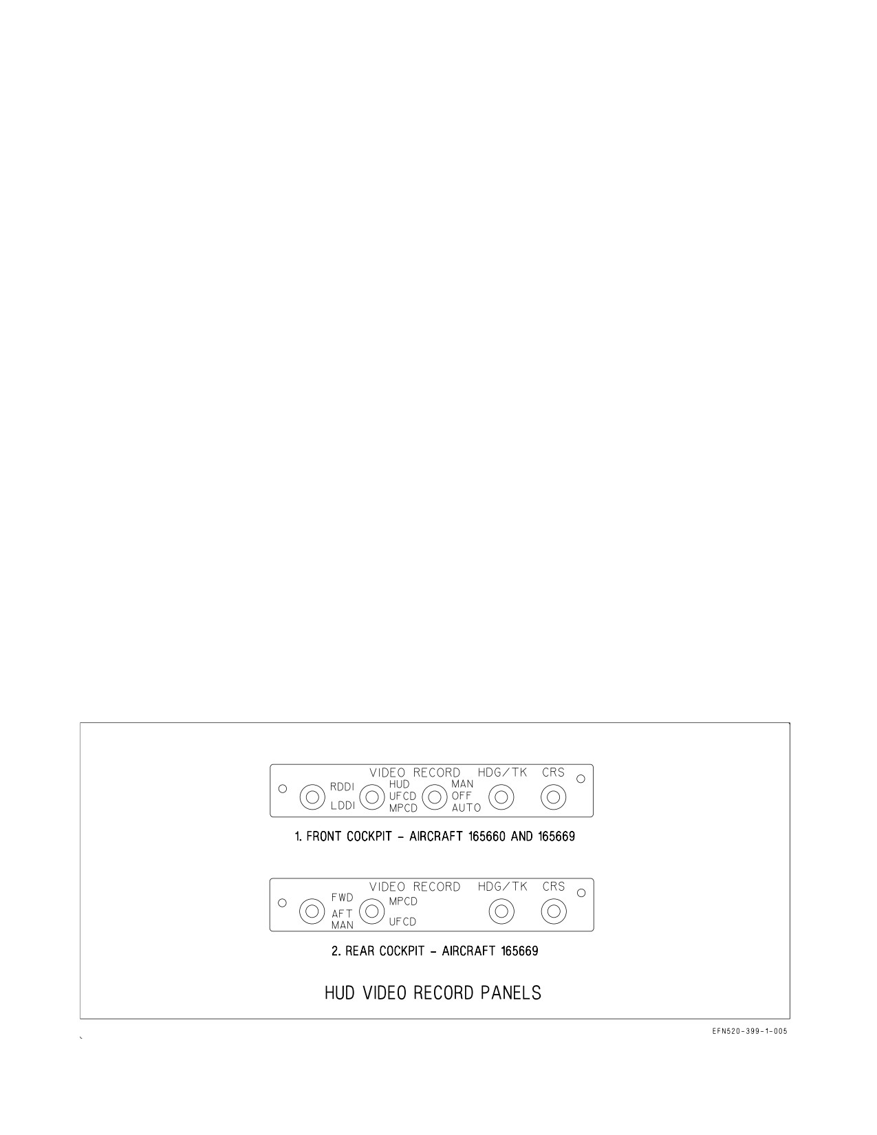
B.2.22.5 HUD Video Record Panel (Aircraft 165660 and 165669). See figure B2-60 for HUD video
record panel applicable to aircraft 165660 and 165669.
B.7.1.3 Exterior Inspection. This section was deleted from NATOPS. Verify the LEX vents are
FULL UP and their condition is satisfactory.
B.7.1.5 Interior Checks - Pilot.
Left Console -
17. EXT LT panel - SET
a. STROBE switch - BRT or DIM
b. FORMATION knob - AS REQUIRED
c. POSITION knob - AS REQUIRED
Pedestal Panel (LOT 21 Aircraft) -
1. ECM JETT button - NOT PUSHED IN
2. DISPENSER switch - OFF
3. ECM knob - OFF
4. DECOY switch - OFF
5. AUX REL switch - NORM
6. RWR switch - OFF
Figure B2-60. HMD Controls
B-4
ORIGINAL
A1-F18EA-NFM-000
7. Clock - CHECK AND SET
8. RUD PED ADJ lever - ADJUST PEDAL POSITION
B.7.2.2 Engine Start Checks (LOT 21 Aircraft).
2. There is no battery gauge for aircraft.
10. MC OFP 13E commands ROLL OUT, ROLL OUT while MC OFP 18E commands ROLL
LEFT, ROLL LEFT.
11. There is no battery gauge for aircraft.
NOTE
Slow canopy movement, EFD blanking, or uncommanded APU
shutdown is indicative of a weak battery.
B.8.2.6 Takeoff Checks.
For MAX power catapult launches only -
2. ABLIM option - BOX
NOTE
Prior to OFP 18E, the ABLIM option may be misinterpreted as a DDI
caution due to similar font size and location. There is no ABLIM
caution.
B.11.1.3 Flaps AUTO Handling Qualities (Before OFP 18E-004).
Flight test showed the most sensitive area for over-g to be localized around 20,000 feet and
0.93 IMN
even with a nominal CG.
B.Figure 12-1. Advisory Displays. (LOTs 21 - 22 Aircraft)
Advisory Lights
INDICATOR
• CAUSE / REMARKS
CORRECTIVE ACTION
AAA
• AAA threat detected.
1. Refer to A1-F18EA-TAC-Series.
AI
• Airborne threat detected
1. Refer to A1-F18EA-TAC-Series.
DISP
• ALE-47 dispense activated.
1. Refer to A1-F18EA-TAC-Series.
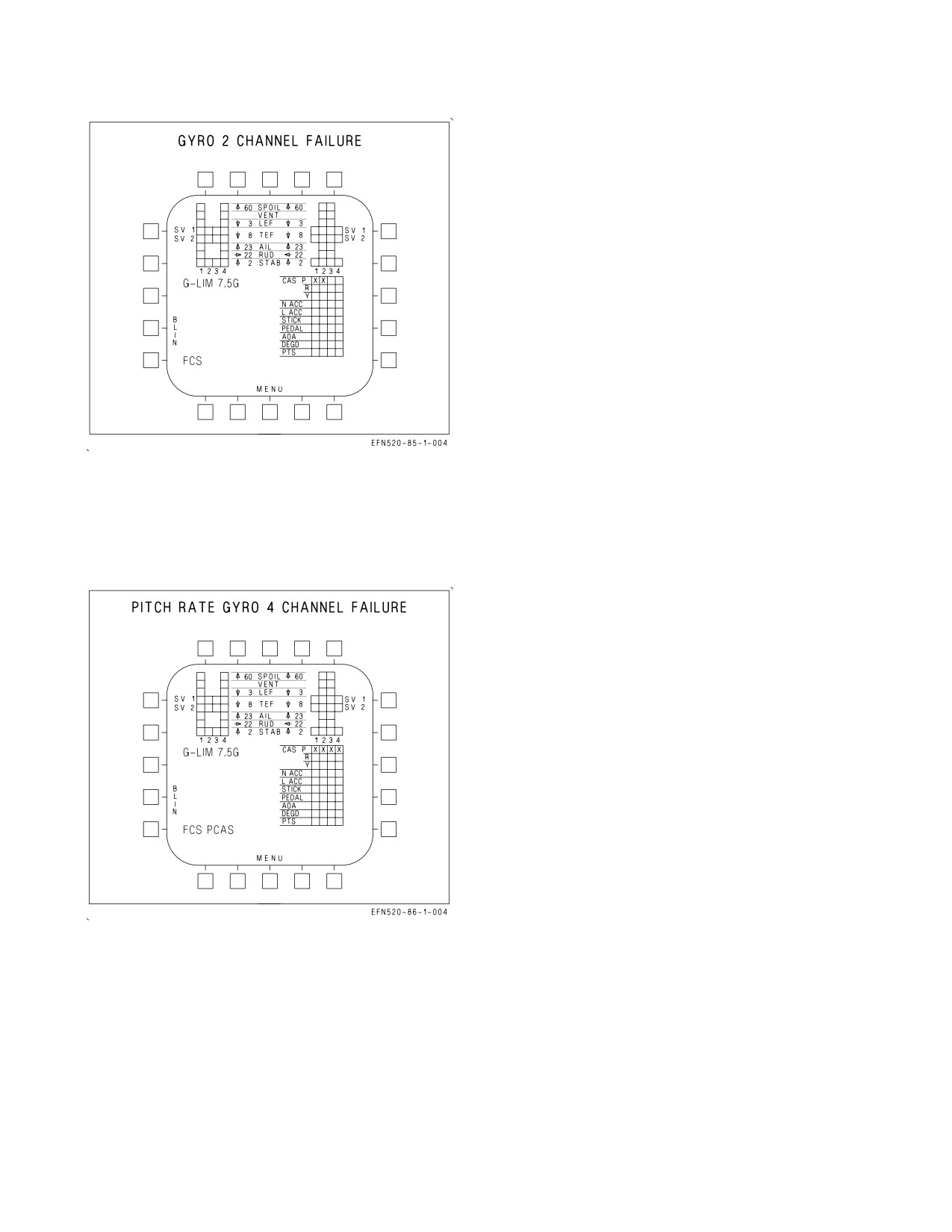
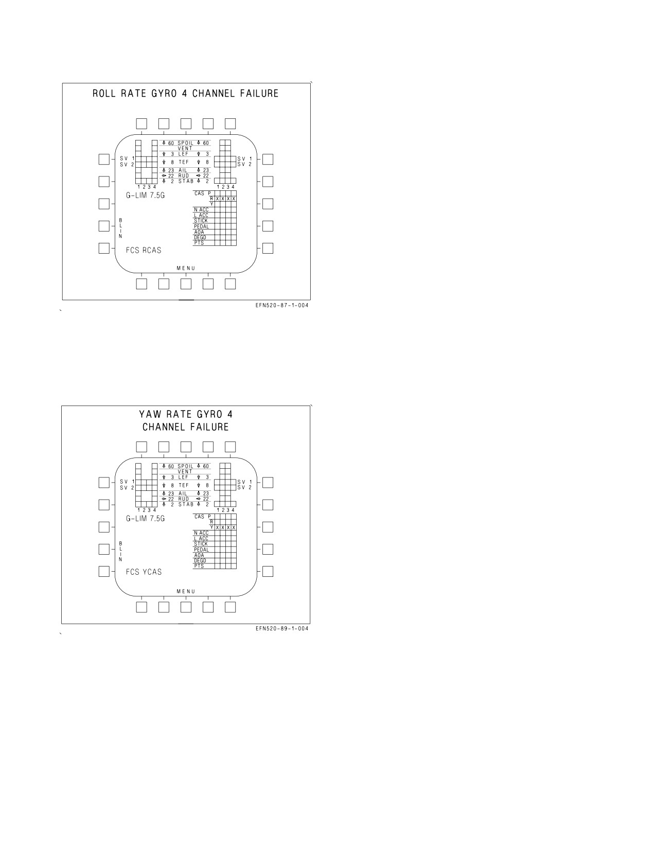
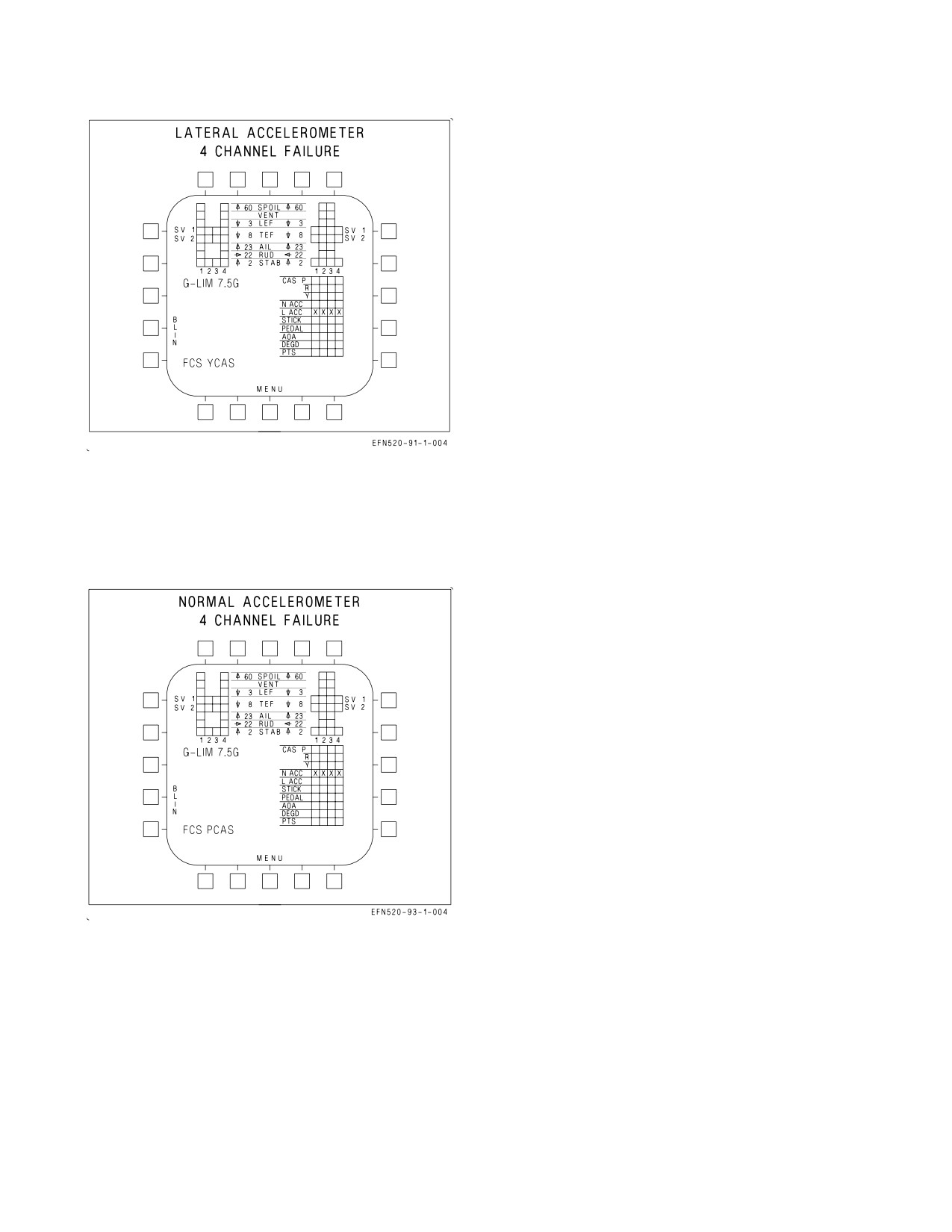
B.15.13 FCS FAILURE INDICATIONS AND EFFECTS (LOT 21 Aircraft).
Figure 15-24, Spoiler Channels 1 and 4 or 2 and 3 Failure, engine bleed air may be degraded at high
Mach number with spoiler failed closed and flaps AUTO.
B-5
ORIGINAL
A1-F18EA-NFM-000
Figures B.15-37 thru B.15-40, and figures B.15.43 and B.15.44, are applicable to these aircraft.
B.23.2.1 ICS VOL Control Knobs (LOT 21 Aircraft). The ICS VOL control knobs are located on the
VOL control panel on the left console in each cockpit. The knobs are stacked in pairs, upper and lower.
Clockwise rotation increases headset volume for the controlled sub-system from the LO to the HI
position. The six knobs control the indicated sub-system and are labeled as follows:
1. TACAN morse code identification (TCN knob (upper))
2. Intercockpit and aircrew/ground crew voice (ICS knob (lower))
3. ALR-67 tones (RWR knob (upper))
4. ECM equipment (when installed) (ECM knob (lower))
5. AIM-9 seeker audio (WPN knob (upper))
6. Unused (AUX knob (lower))
The ground crew headset plug in jack and ICS volume control knob are located in door 8R on the
right side of the forward fuselage.
B.23.7 DCS - DIGITAL COMMUNICATION SYSTEM
LOT 21 Aircraft do not incorporate DCS.
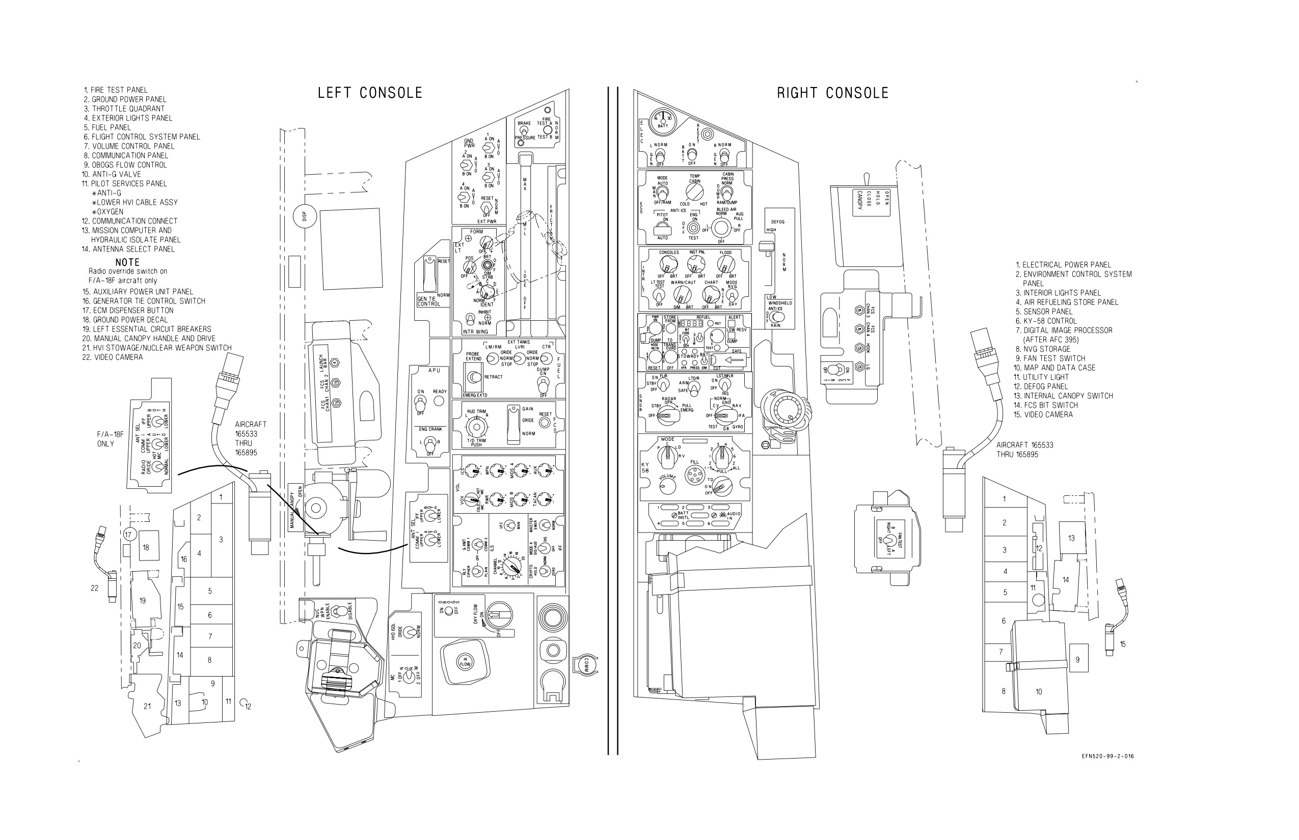
Foldouts. Refer to figures B-FO-1 and B-FO-2 for specific cockpit component locations.
B-6
ORIGINAL
A1-F18EA-NFM-000
NOTE
FCS status display is shown for pitch
rate gyro channels
1
and 2 failure
example.
EFFECTS:
No change in flying qualities.
Autopilot inoperative.
Figure B15-37. FCS Failure Indications and
Effects
EFFECTS:
Autopilot inoperative
ATC inoperative
Sensitive dynamic pitch characteristics.
Aggressive pitch inputs may result in PIO.
Figure B15-38. FCS Failure Indications and
Effects
B-7
ORIGINAL
A1-F18EA-NFM-000
EFFECTS:
Degraded roll CAS.
Reduced roll damping.
Autopilot inoperative.
Flaps - HALF or FULL:
Sluggish roll response.
Lateral PIO tendency.
Figure B15-39. FCS Failure Indications and
Effects
EFFECTS:
Autopilot inoperative.
ASRM inoperative.
Flaps - AUTO:
Poor dutch roll damping.
Large sideslip with lateral stick.
Flaps - HALF or FULL:
Poor dutch roll damping.
Large sideslip with full rudder pedal.
Lateral PIO tendency.
Directional PIO may occur during aggressive
ground tracking.
Figure B15-40. FCS Failure Indications and
Effects
B-8
ORIGINAL
A1-F18EA-NFM-000
EFFECTS:
Degraded yaw CAS.
Autopilot inoperative.
Flaps - HALF or FULL:
Large sideslips with full rudder pedal.
Figure B15-43. FCS Failure Indications and
Effects
EFFECTS:
Autopilot inoperative.
ATC inoperative.
Spin recovery arrow not provided, but ASRM
still available.
Flaps - AUTO:
Degraded pitch CAS.
Flaps - HALF or FULL:
No change in flying qualities.
Figure B15-44. FCS Failure Indications and
Effects
B-9
ORIGINAL
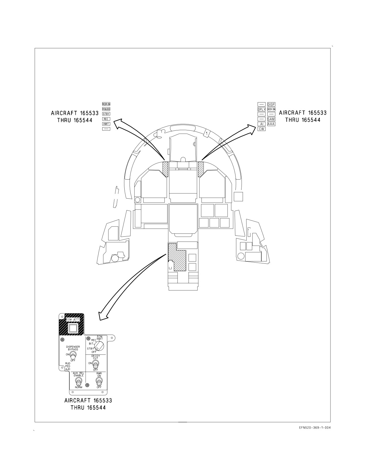
A1-F18EA-NFM-000
Figure B-FO-1. Cockpit F/A-18E/F (Sheet 1 of 2)
B-10
ORIGINAL
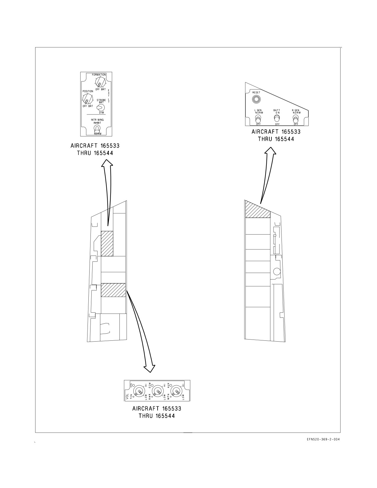
A1-F18EA-NFM-000
Figure B-FO-1. Cockpit F/A-18E/F (Sheet 2 of 2)
B-11
ORIGINAL
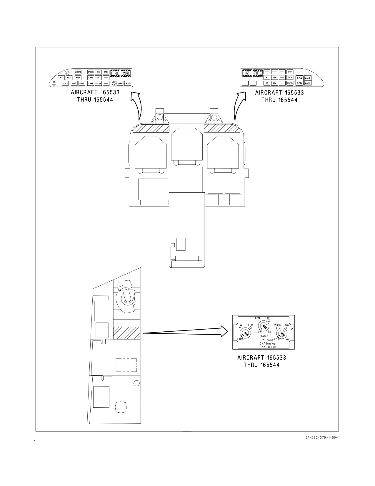
A1-F18EA-NFM-000
Figure B-FO-2. Rear Cockpit F/A-18F
B-12
ORIGINAL
A1-F18EA-NFM-000
FOLDOUTS
TABLE OF CONTENTS
Cockpit F/A-18E/F (Lots 21 thru 25)
FO-3
Rear Cockpit F/A-18F (Lots 21 thru 25)
FO-7
Cockpit F/A-18E/F (Lot 26 AND UP)
FO-11
Rear Cockpit F/A-18F (Lot 26 AND UP)
FO-15
Electrical Bus Power
FO-19
Ejection Seat
FO-21
Fuel System
FO-25
Environmental Control System
FO-29
FOLDOUT SECTION
The purpose of the Foldout Section is to make these illustrations available for ready reference while
reading the associated text. The illustrations are referenced from several sections of the manual and are
referred to in the text as (see figure FO-, foldout section).
The System Foldouts are simplified to provide a general understanding of complicated systems.
They do not contain all components, circuits, etc. For a complete diagram(s) of a system, refer to the
applicable maintenance publication.
FO-1 (Reverse Blank)
ORIGINAL
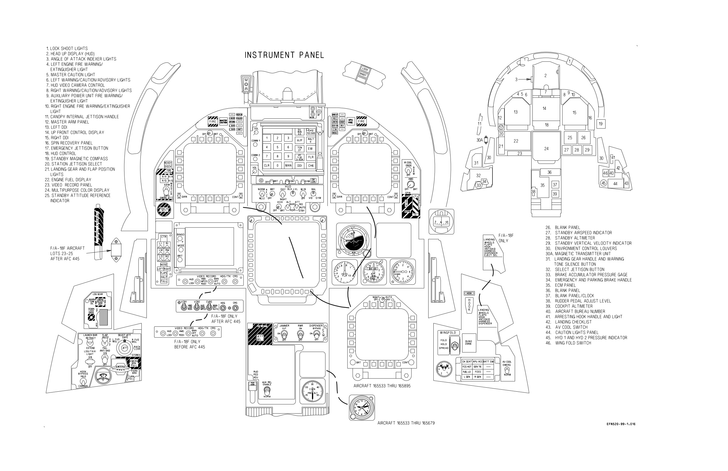
A1-F18EA-NFM-000
Figure FO-1. Cockpit F/A-18E/F (Lots 21 thru 25) (Sheet 1 of 2)
FO-3 (Reverse Blank)
ORIGINAL
A1-F18EA-NFM-000
Figure FO-1. Cockpit F/A-18E/F (Lots 21 thru 25) (Sheet 2 of 2)
FO-5 (Reverse Blank)
ORIGINAL
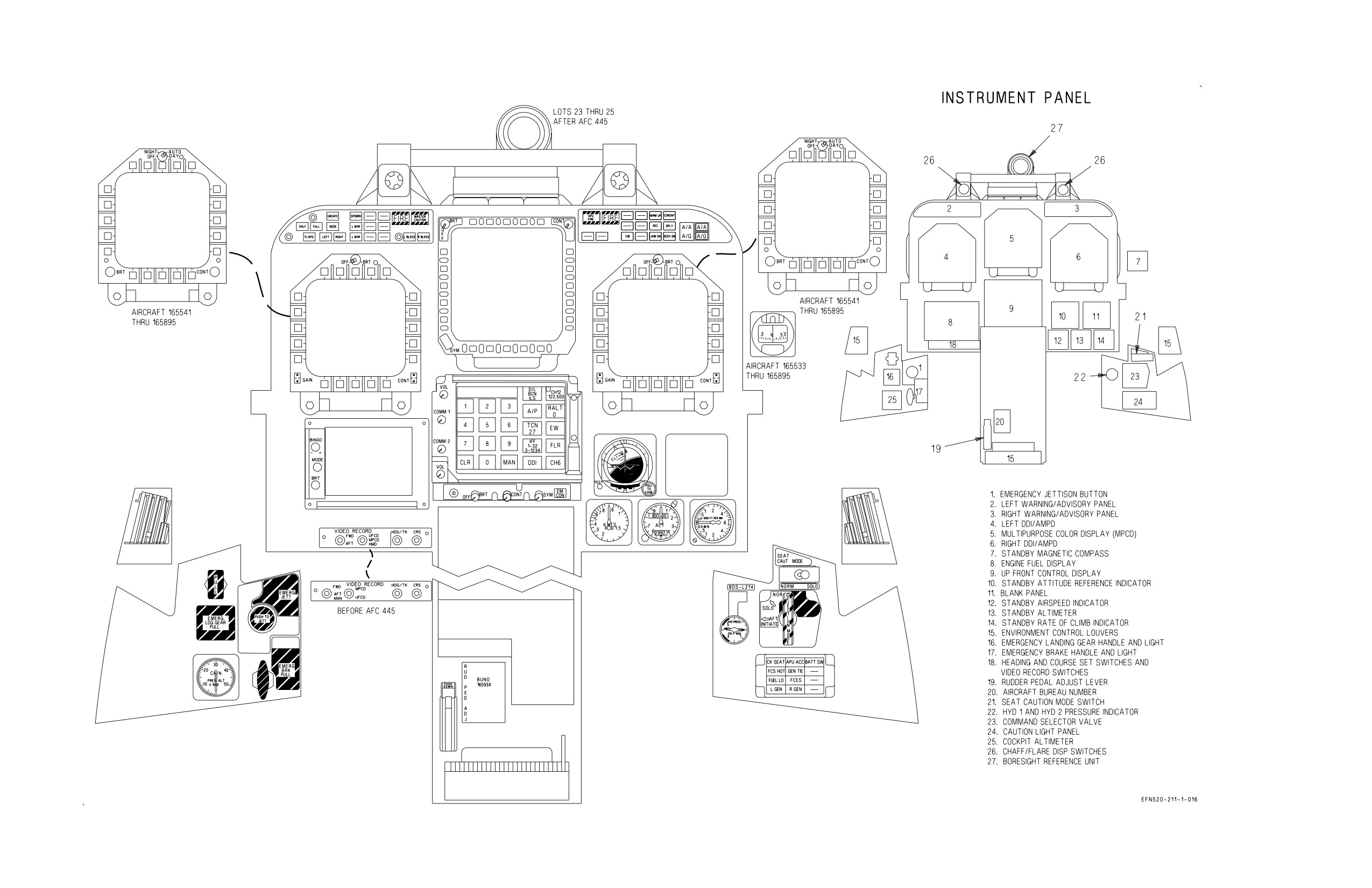
A1-F18EA-NFM-000
Figure FO-2. Rear Cockpit F/A-18F (Lots 21 thru 25) (Sheet 1 of 2)
FO-7 (Reverse Blank)
ORIGINAL
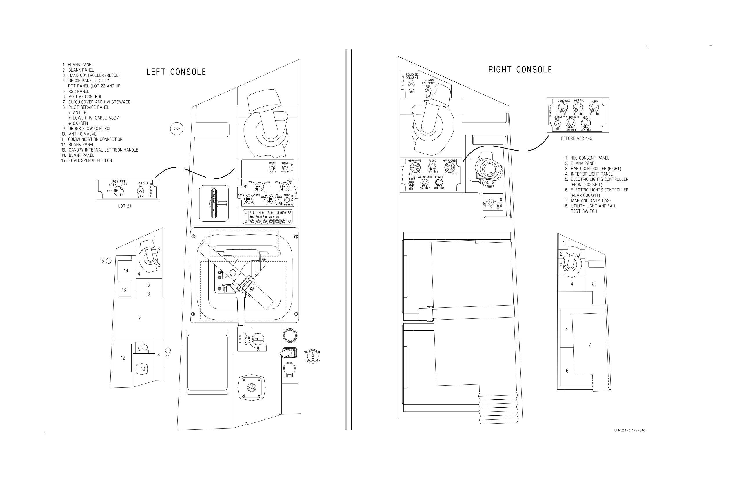
A1-F18EA-NFM-000
Figure FO-2. Rear Cockpit F/A-18F (Lots 21 thru 25) (Sheet 2 of 2)
FO-9 (Reverse Blank)
ORIGINAL
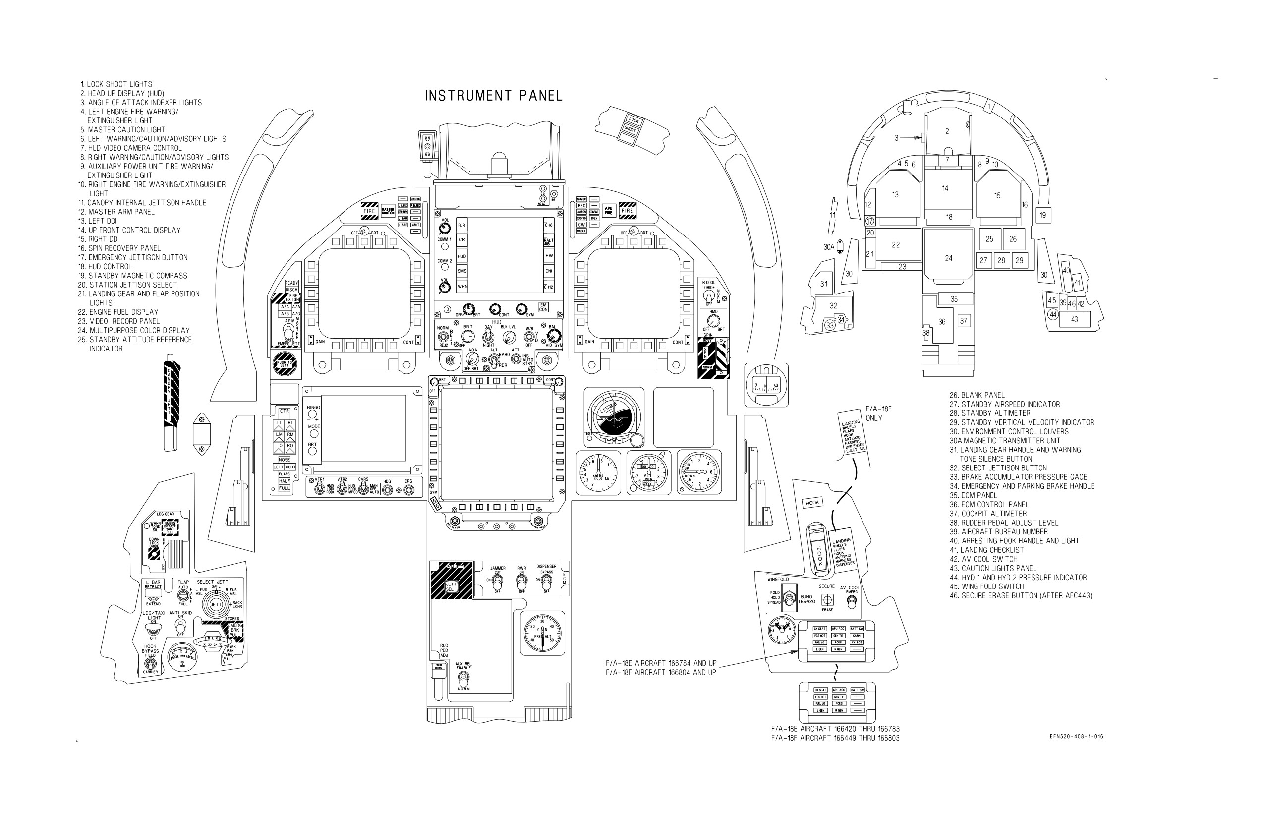
A1-F18EA-NFM-000
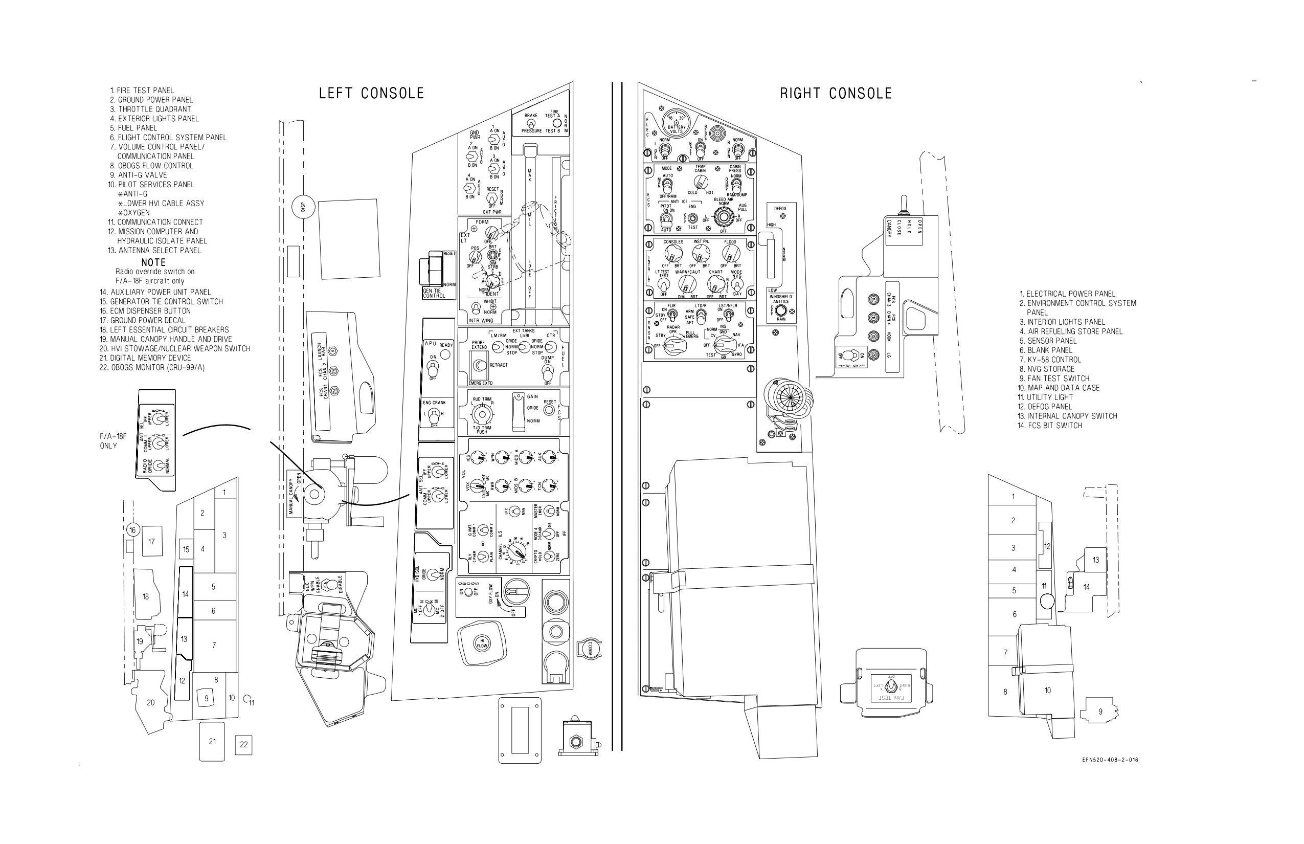
Figure FO-3. Cockpit F/A-18E/F (Lot 26 AND UP) (Sheet 1 of 2)
FO-11 (Reverse Blank)
ORIGINAL
A1-F18EA-NFM-000
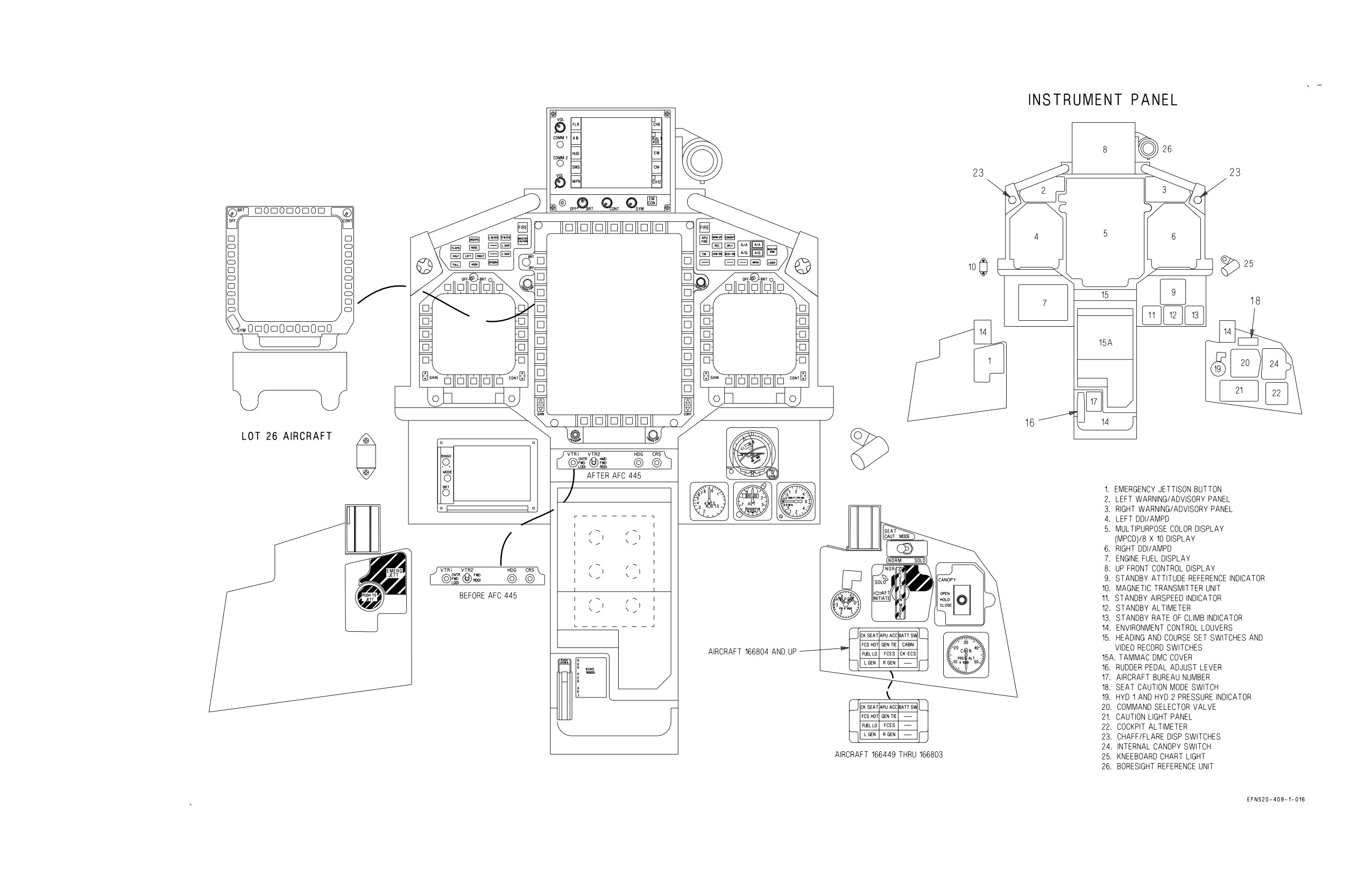
Figure FO-3. Cockpit F/A-18E/F (Lot 26 AND UP) (Sheet 2 of 2)
FO-13 (Reverse Blank)
ORIGINAL
A1-F18EA-NFM-000
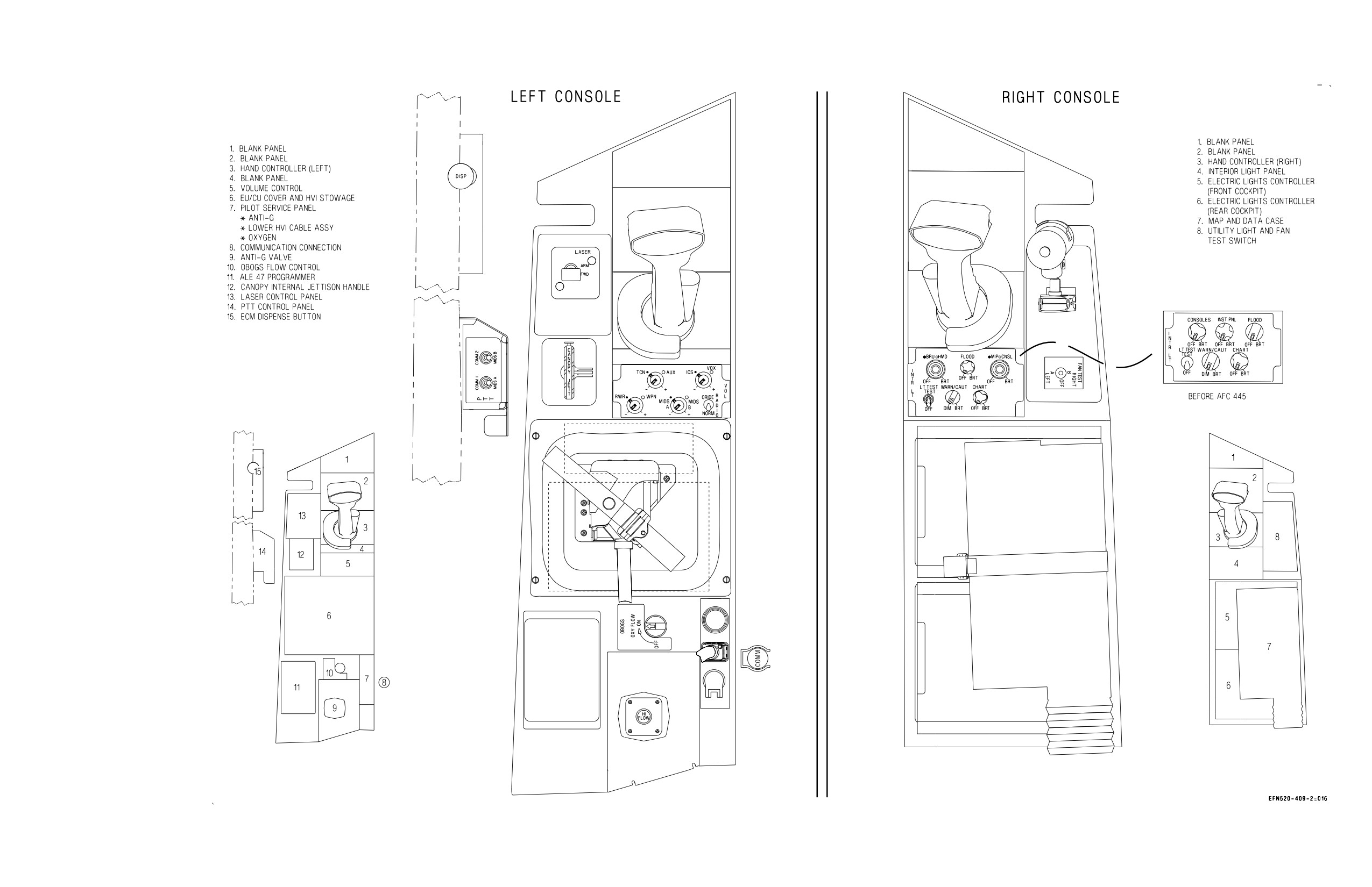
Figure FO-4. Rear Cockpit F/A-18F (Lot 26 AND UP) (Sheet 1 of 2)
FO-15 (Reverse Blank)
ORIGINAL
A1-F18EA-NFM-000
Figure FO-4. Rear Cockpit F/A-18F (Lot 26 AND UP) (Sheet 2 of 2)
FO-17 (Reverse Blank)
ORIGINAL
A1-F18EA-NFM-000
ALE-50 CONTROLLER
BATT CHARGER
CSC (AC)
ICE DETECTOR (AC)
R AOA HEATER (AC)
RDDI(s)
TACAN
APPROACH LTS (AC)
BATT HEATER
CVRS (AC)
INTERFERENCE
R ECS DUCT DOOR
RECCE WINDOW DEFOG
TACTS (AC)
RIGHT 115
ARM STA 6 THRU 11
COCKPIT STROBE
GPS
BLANKER
R PITOT HEATER
SMS (AC)
TK 1 XFR PUMP
VOLT AC BUS
ARS POWER
LIGHT
HARM CLC (AC)
JHMCS
R TR
STBY ATTITUDE
26 VAC AUTO XFMR
AVIONICS GROUND
COOLING FAN
HUD (AC)
MC2
R WINGFOLD EDU
REFERENCE
POSITION LTS
RAD ALT
INDICATORS
RIGHT 26 VOLT
ADF
MAGNETIC AZIMUTH DETECTOR (CH 2 & 4)
AC BUS
ALE-47 CONTROLLER
COMM 2
HUD (DC)
ICE DETECTOR (DC)
NVG FLOOD LIGHTS
R PROBE HEATER
SMS (DC)
ALE-47 SEQUENCERS
CPWS PRESSURE
HYD 1 PRESSURE
ICS
R AOA HEATER (DC)
CONTROLLER
TACTS (DC)
RIGHT 28 VOLT
ALE-50 CONTROLLER
SENSING
INDICATOR
INTERIOR LIGHTS
R ENG FADEC CH B
R WING UNLOCK
UNDER COOL SENSOR
DC BUS
ARM STA 6 THRU 11
CSC (DC)
HYD 2 PRESSURE
LGCU
R PRIMARY BLEED
MOTOR
CBN RAM AIR VALVE
CVRS (DC)
INDICATOR
LST/CAM
AIR SHUTOFF VALVE
SECONDARY BLEED
CK ECS CAUTION LT
ECS CONTROLLER
AIR SHUTOFF VALVE
HARM CLC (DC)
APU CONTROL
CROSSFEED VALVE
ENG START
FCS AV COOL
FUEL DUMP
R ENG FADEC CH A
SMS
BK PRESS IND
CROSS COOLING
CONTROL
ACTUATOR
ICS
R ENG OIL PRESSURE
STBY ALTIMETER
ESSENTIAL
BL AIR LK DET ABL
VALVE
FCES 1 (EBB)
FEED TK SHUTOFF
IFF EMERG
INDICATOR
STBY ARI (FRONT
28 VOLT
AIR LK DET B
EMER JETT STAs
FCES 2 (EBB)
VALVE
L ENG FADEC CH A
R FUEL S/O VALVE
COCKPIT ONLY)
CABIN EMERG VENT
(2, 3, 4, 6, 9, 10)
FCES 3 (EBB)
FIRE DET LOOP A
L ENG OIL PRESSURE
R LG PROXIMITY
UTILITY LIGHTS
DC BUS
VALVE
EMER PROBE EXTEND
FCES 4 (EBB)
FIRE DET LOOP B
INDICATOR
SWITCH
WARNING/CAUTION
CK ECS CAUTION LT
EFD
FIRE EXTINGUISHER
PITCH TRIM
LIGHTS
COMM 1
ADF
BUS TIE
EXT FUEL TANK
FUEL TRANSFER
L BLEED AIR CONT
LAUNCH BAR CONTROL
PROBE CONTROL
ALE-47 SEQUENCERS
CK ECS CAUTION LT
CONTROL
VALVES
VALVE (PRIM)
VALVE
RADAR (DC)
ALR-67 (DC)
DATA LINK
EXT LTS CONTROL
GND PWR CONTROL
L ENG FADEC CH B
LG CONTROL VALVES
SEAT ADJ (FRONT &
LEFT 28 VOLT
ANTI-SKID CONTROL
DBFSS
FCCB ASYM BRK DC
GUN
L PROBE HEATER
MEMORY UNIT (MU)
REAR)
UNIT
DFIRS POWER
FUEL LOW LEVEL
HOOK LIGHT
CONTROL
MSTR ARM
THROTTLE
DC BUS
ANTENNA SELECT
DIG MAP SET (DC)
WARNING
HOSE JETTISON
L WINGFOLD UNLOCK
NWS CONTROL VALVE
BACKDRIVE
ANAV
ECM COOLING
FUEL TK PRESS
HYD ISOL ORIDE
MOTOR
OBOGS CONTROL
WSHLD ANTI-ICE
BCN AUGMENTATOR
ENG IDL/A-B LKOUT
VALVES
ILS (DC)
REMOVAL
LEFT 115 VOLT
ALQ-165 ASPJ
EMERG AV COOLING
ILS (AC)
L PITOT HTR
LCS FAN
MC1
PROBE LT
ALR-67 (AC)
FAN
INS
L TR
LCS PUMP
MPCD(s)/UFCD(s)
RADAR (AC)
AC BUS
ARM STA 1 THRU 5
FORMATN LTS
L AOA HTRS (AC)
L WING FOLD EDU
LDDI(s)
OBOGS CONCENTRATOR
STROBE LTS
DIG MAP SET (AC)
IFF
L ECS DUCT DOOR
LDG/TAXI LT
MAINTENANCE
APU PRIM
GEN TIE LOGIC
SDC
CANOPY
INS KEEP ALIVE
SMP (CODE CHECK)
BUS
FCS KEEP ALIVE CH 1
LADDER DEPLOY
VENT TANK WET
THRU 4
LIGHT
Figure FO-5. Electrical Bus Power
FO-19 (Reverse Blank)
ORIGINAL

A1-F18EA-NFM-000
Figure FO-6. Ejection Seat (Sheet 1 of 2)
FO-21 (Reverse Blank)
ORIGINAL
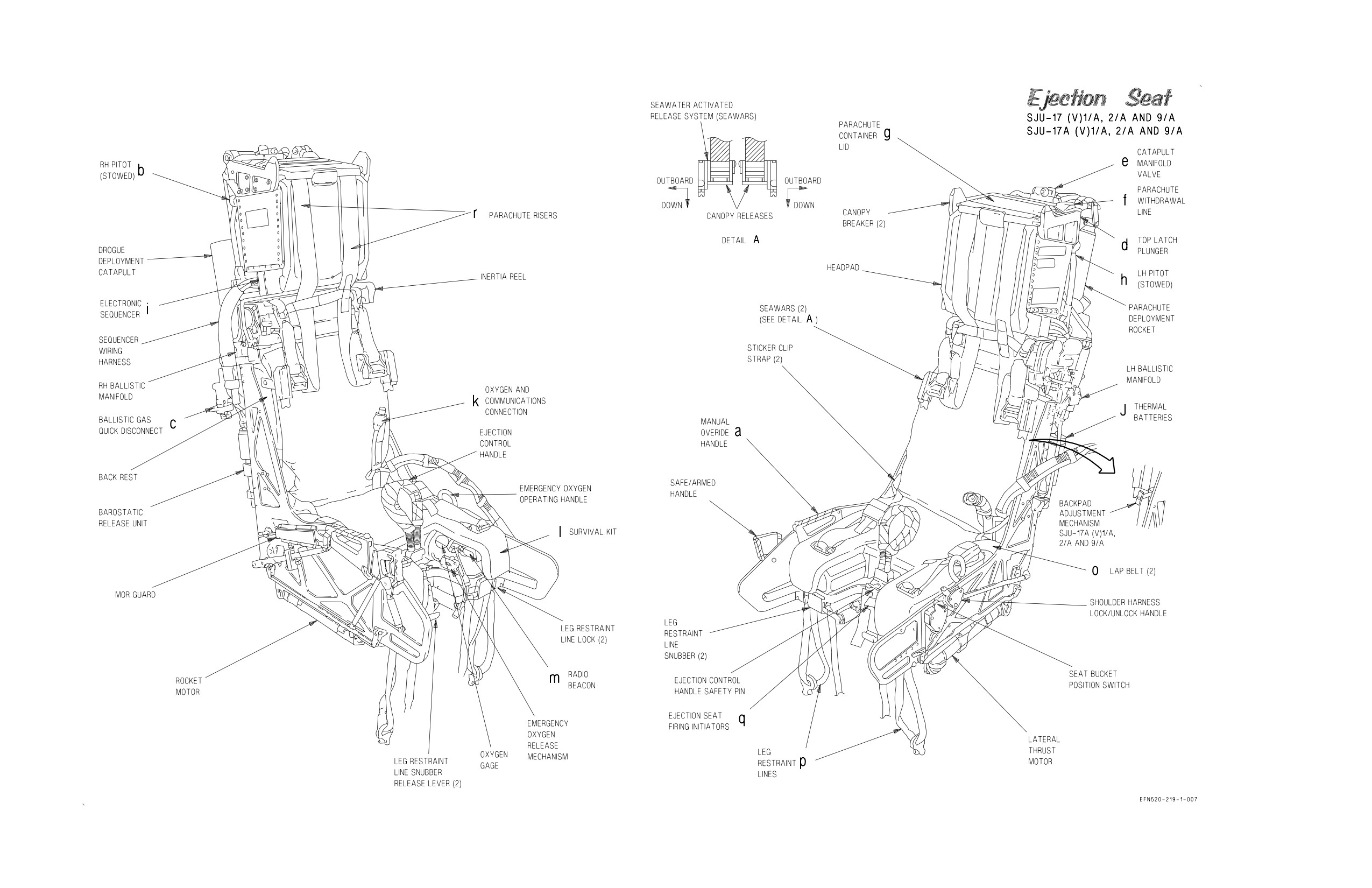
A1-F18EA-NFM-000
Figure FO-6. Ejection Seat (Sheet 2 of 2)
FO-23 (Reverse Blank)
ORIGINAL
A1-F18EA-NFM-000
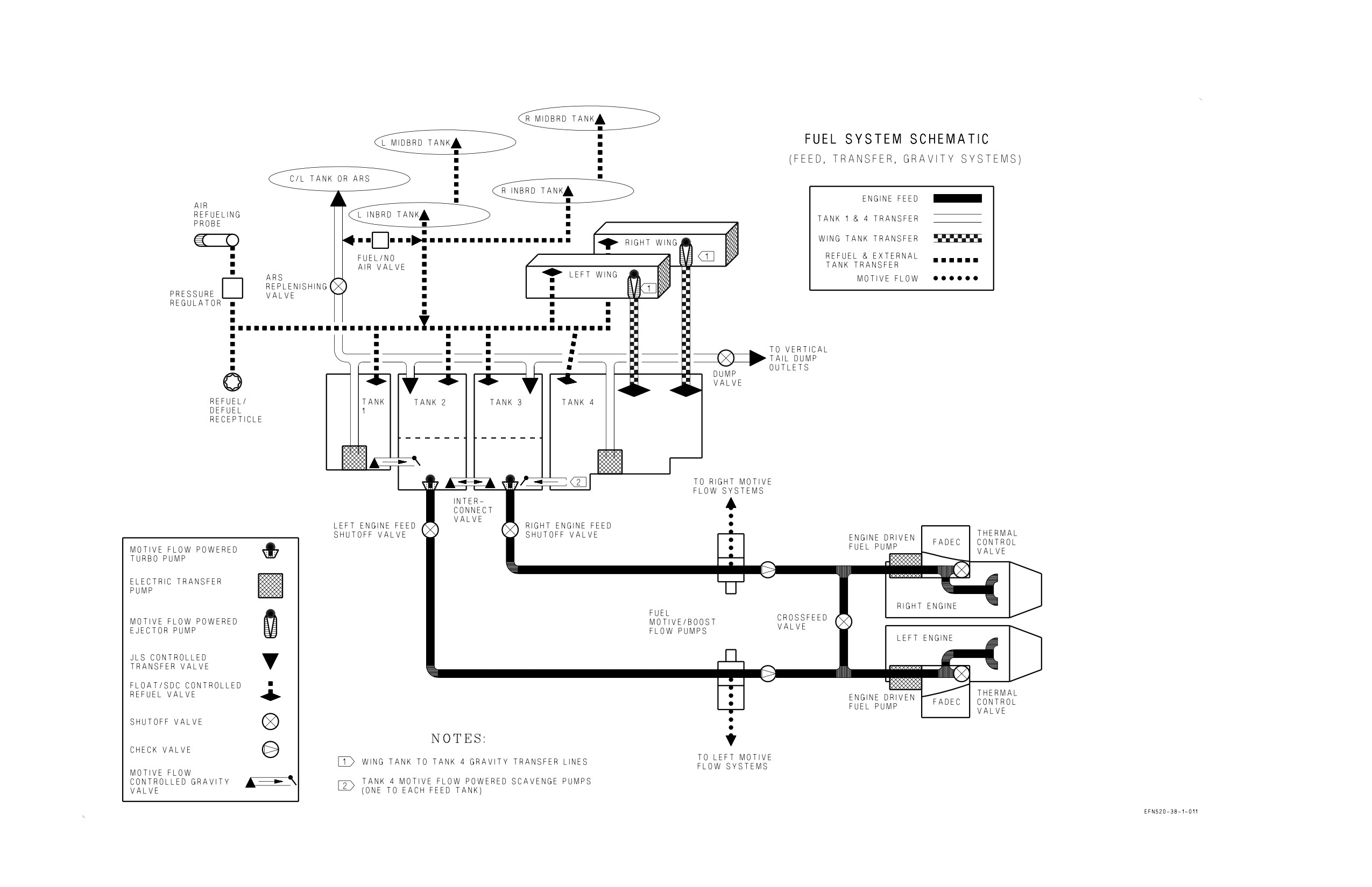
Figure FO-7. Fuel System (Sheet 1 of 2)
FO-25 (Reverse Blank)
ORIGINAL
A1-F18EA-NFM-000
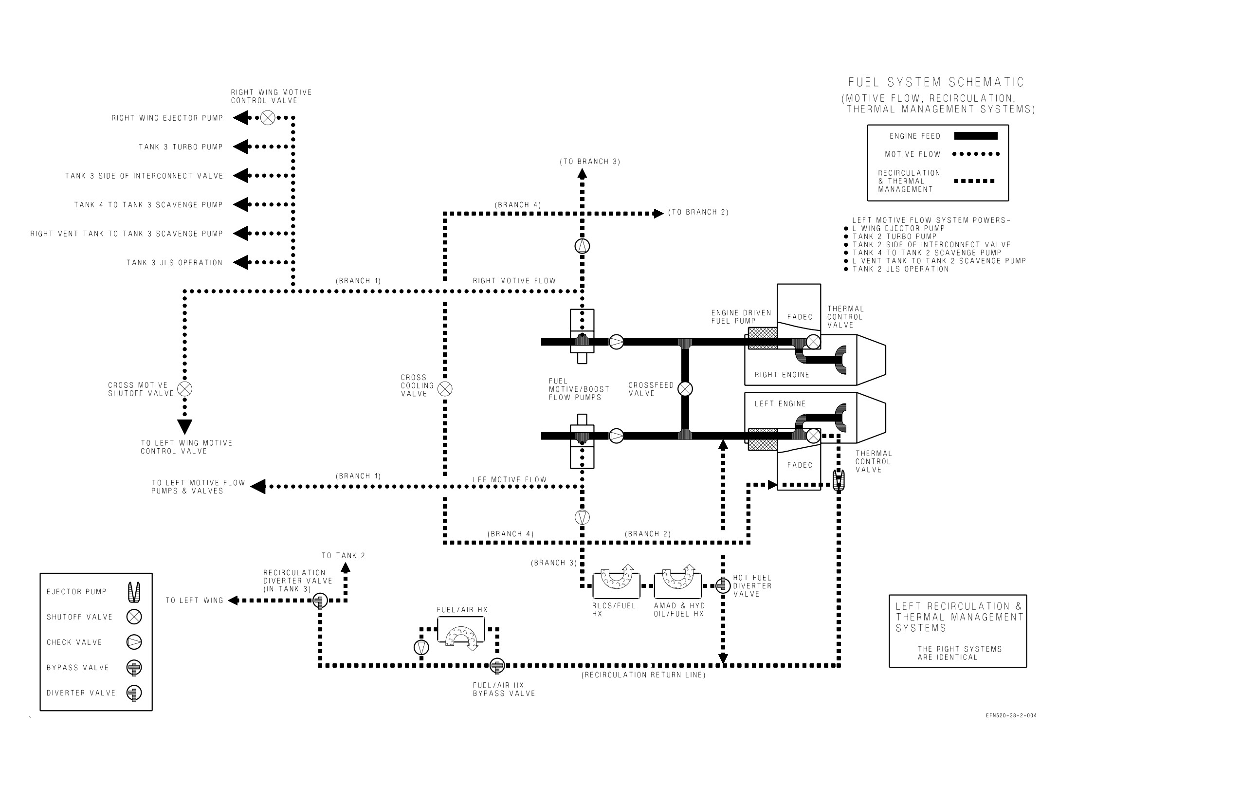
Figure FO-7. Fuel System (Sheet 2 of 2)
FO-27 (Reverse Blank)
ORIGINAL
A1-F18EA-NFM-000
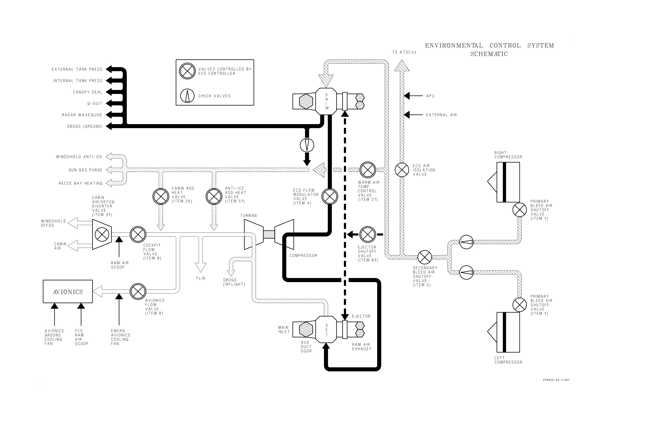
Figure FO-8. Environmental Control System
FO-29 (Reverse Blank)
ORIGINAL
A1-F18EA-NFM-000
ALPHABETICAL INDEX
Page
No.
1
10,000 Feet Checks
III-10-24, III-10-31, III-10-34
10,000 Feet to Landing
III-10-28
10,000 Foot Checks
III-7-33
2
24.2.4 Navigation System BIT
VII-24-23
5
5-Wet (4-EFT and ARS) Loading Handling Qualities
IV-11-6
5-Wet Loading with 5-Wet FCC Gains not Set
IV-11-6
8
8 x 10 Display
I-2-151
8 x 10 Display Initiated BIT
I-2-199
A
A/A Weapon Select Switch
I-2-88
ABLIM - Afterburner Limiting Function
I-2-5
ABORT
V-14-2, V-18-3
Aborted Takeoff
III-9-1
AC Electrical Power
I-2-30
Acceleration Limitations
I-4-5
ACI Configuration Check
I-2-140
ACL Mode 1
VII-24-66
ACL MODE 1 AND 1A APPROACHES
III-8-15
ACL Mode 1A
VII-24-70
ACL Mode 2
VII-24-70
ACL MODE 2 APPROACH
III-8-18
ACL Mode Displays
VII-24-61
ACL Mode Operation
VII-24-65
ACL Option (HSI Format)
VII-24-9
Adaptability/Flexibility
IX-28-1
ADF (AUTOMATIC DIRECTION FINDER)
VII-24-51
Aerobraking Technique
III-7-40
AFCS - AUTOMATIC FLIGHT CONTROL SYSTEM
I-2-84
AFCS Mode Deselection
I-2-86
AFCS Mode Selection
I-2-84
AFCS Related Caution and Advisories
I-2-87
Aft Cooling Fan Shutoff Valve
I-2-98
Aft UFCD MUX FAIL
I-2-168
Index-1
ORIGINAL
A1-F18EA-NFM-000
Page
No.
After Landing
III-7-43
AFTER LANDING
VI-21-2
After Landing Checks
III-7-43, III-10-29
After Takeoff Checks
III-7-33, III-10-21
AFTERBURNER FAILURE
V-15-1
A/G Weapon Release Button
I-2-90
AGI (Armament Gas Ingestion) Protection
I-2-5
AHRS Failure Flying Qualities
IV-11-17
AILERON HINGE FAILURE - SUSPECTED, INBOARD
V-15-47
AIR COMBAT MANEUVERING
IV-11-7
Air Conditioning System (ACS) Pack
I-2-97
Air Data Function
I-2-72
Air Refueling Checklist
III-9-5
AIR REFUELING (RECEIVER)
III-9-5
Air Refueling Store (ARS)
III-9-9
AIR REFUELING (TANKER)
III-9-9
AIRBORNE CHECKS
III-7-33
Airborne HMD Accuracy Check with CATM/AIM-9X
III-9-23
Airborne HMD Accuracy Check with Radar
III-9-23
AIRBORNE HMD ACCURACY CHECKS
III-9-22
Aircraft (A/C) Programming
VII-24-35
Aircraft Attitude Data
I-2-215
AIRCRAFT DESCRIPTION
I-1-1
Aircraft Gross Weight
I-1-2
AIRCREW RESPONSIBILITIES BY FLIGHT PHASE
IX-28-3
Airspeed during Ejection
V-17-2
Airspeed Limitations
I-4-1
Air-to-Air Gun Tracking
IV-11-7
AJ MENU From Fixed Frequency COMM Sublevel
VII-23-13
AJ MENU From Have Quick COMM Sublevel
VII-23-20
AJ MENU From SINCGARS COMM Sublevel
VII-23-21
ALE-47 Advisories
I-2-185
ALE-47 Countermeasures Dispensing Set
I-2-185
ALE-47 DISP Switch
I-2-95
ALE-50 BIT Anomalies
I-2-185
ALE-50 Decoy Dispensing Set
I-2-185
Alert Five Launch
III-9-21
ALERT Indicators
III-9-11
ALERT SCRAMBLE LAUNCH PROCEDURES
III-9-20
Alignment Exit
I-2-214
Alignment Verification
I-2-214
All Equipment
I-2-193
ALT Selector Switch
I-2-157
Altitude Required for Recovery (ARR)
I-2-134
AMAD - Airframe Mounted Accessory Drive
I-2-27
AMAD Related Cautions
I-2-29
AMU Maintenance Format Options and Display Information
I-2-181
AMU/PC Cards Cautions and Advisories
I-2-184
Index-2
ORIGINAL
A1-F18EA-NFM-000
Page
No.
ANAV
VII-24-23
ANGLE OF ATTACK (AOA) FAILURE
V-15-44
Angle Of Attack Indexer
I-2-141
ANTI SKID Switch
I-2-53
Anti-g System
I-2-104
Anti-Jam Operation
VII-23-13
Anti-skid BIT and the ANTISKID Caution
I-2-53
Anti-skid System
I-2-51
AOA Indexer Control Knob
I-2-157
AOA Limit Display
I-4-5
AOA Limitations - Flaps AUTO
I-4-5
AOA PROBE DAMAGE OR BINDING
V-15-45
AOA PROBE SELECTION
V-15-46
AOA Probes
I-2-72
AOA Warning Tone
I-2-76
Applicable Publications
X-30-4
Approach
III-9-6, III-9-19, IX-29-5
Approach Lights
I-2-39
Approaches
VI-19-2
Approach/Landing (*)
X-30-4
APU - Auxiliary Power Unit
I-2-28
APU Fire Extinguishing System
I-2-113
APU FIRE Light
I-2-112
APU FIRE LIGHT
V-18-1
APU READY Light
I-2-28
APU Switch
I-2-28
ARC-210/DCS
VII-23-28
Area
X-30-2
Arrested Landing
III-9-19
ARRESTED LANDING AND EXIT FROM THE LANDING AREA
III-8-20
Arresting Gear Types
V-16-13
Arresting Hook System
I-2-58
ARRESTMENT - FIELD
V-16-13
Arrestment - Long Field
V-16-14
Arrestment - Short Field
V-16-14
Arrestment and Exit From the Landing Area
III-8-23
Arrestment Decision
V-16-14
ARS DROGUE Caution
III-9-12
ARS Hose Fails to Retract
V-15-25
ARS Hydraulic Pressure Light
V-15-25
ARS Interior Checks -
III-9-13
ARS Jettison
III-9-18
ARS Limitations
I-4-17
ARS Limitations
III-9-18
ARS MALFUNCTIONS
V-15-25
ARS Refueling Hose Jettison
V-15-25
ARS (Tanker) Procedures
III-9-12
Assertiveness
IX-28-1
Index-3
ORIGINAL
A1-F18EA-NFM-000
Page
No.
Asymmetric Stores Landings
III-7-43
ATC - Automatic Throttle Control
I-2-10
ATC Approach Mode Technique
III-8-14
ATC Approaches
III-7-38
ATC Automatic Disengagement
I-2-11
ATC Disengagement
I-2-11
ATC Engagement
I-2-10
ATC Related Cautions
I-2-11
ATFLIR Limitations
I-4-19
ATS Air Sources
I-2-28
ATS Protection
I-2-29
ATT Selector Switch
I-2-157
AUG PULL
I-2-29, I-2-101
AUTO BIT
I-2-196
AUTO Option (HSI Format)
VII-24-8
AUTO Sequential Steering
VII-24-44
AUTO Update
VII-24-39
Automatic Battery Cutoff
I-2-33
Automatic Carrier Landing Mode
VII-24-59
Automatic Erase
I-2-145
AUX REL Switch
I-2-129
AV COOL Switch
I-2-63, I-2-105
Avionics BIT
I-2-186
Avionics Cooling Fans
I-2-98
AVIONICS SUBSYSTEM
I-2-142
B
Backpad Adjustment Mechanism (SJU-17A (V)1/A, 2/A, and 9/A)
I-2-126
BACKUP ATTITUDE AND NAVIGATION SYSTEM
VII-25-2
Backup Attitude and Navigation System Controls and Indicators
VII-25-3
Backup Erase Controller
I-2-146
BACKUP FREQUENCY CONTROL
VII-25-6
Backup Heading Mode Control
VII-25-5
Backup HSI Display
VII-25-1
Backup HUD Display
VII-25-1
Backup Navigational Information on Backup HUD
VII-25-2
BAL Control Knob
I-2-157
Balanced Cruise Formation
III-9-4
BALT - Barometric Altitude Hold
I-2-86
Barometric (BARO)/Radar Low Altitude Warning Programming
VII-24-35
BARRICADE ARRESTMENT
V-16-14
Basic Autopilot
I-2-86
BATT SW Caution and Caution Light
I-2-33
BATT Switch
I-2-33
Battery
I-2-32
Battery Gauge
I-2-33
Before Engine Shutdown Checks
III-7-45, III-10-29
Before Entering Cockpit
III-7-8
Index-4
ORIGINAL
A1-F18EA-NFM-000
Page
No.
BEFORE ENTERING COCKPIT
VI-22-1
Before Landing
III-9-17
Before Takeoff
VI-19-1
Before Takeoff Checks
III-7-30
Before Taxi
III-8-21
BEFORE TAXI
VI-22-1
BEFORE TAXI CHECKS
III-7-23
Before Taxi Checks
III-8-2, III-10-15, III-10-32
BIT Initiation
I-2-190
BIT Recording On The Memory Unit
I-2-213
BIT Top Level Display
VII-23-32
BITE Flag Indicator
III-9-11
BIT-STATUS MONITORING SUBSYSTEM
I-2-186
Black Level Control Knob
I-2-156
BLEED AIR Knob
I-2-96
Bleed Air Leak Detection (BALD) System
I-2-114
Bleed Air Leak Detection System Test
I-2-114
Bleed Air Shutoff Valves
I-2-95
Bleed Air Subsystem
I-2-96
BLIN Codes
I-2-201
BLOCK NUMBERS
I-1-4
Boarding Ladder
I-2-118
Bolter
III-9-20
Boresight Reference Unit (BRU)
I-2-208
Brake Accumulator Pressure Gauge
I-2-45
BRAKE FAILURE/EMERGENCY BRAKES
V-13-4, V-18-3
Braking Technique
III-7-40
Breathing Regulator
I-2-109
Briefing
III-6-1
BRIEFING/DEBRIEFING
III-6-1
Brightness and Contrast Controls
I-2-150
Brightness Knob - AMCD Aircraft
I-2-147
Brightness Selector Knob - Non-AMCD Aircraft
I-2-147
BRK PRESS Switch
I-2-45
BRT Control Knob - Non-AMCD Aircraft
I-2-147
Built-In Test (BIT)
I-2-211
C
CABIN Caution Light
I-2-103
Cabin Louvers/Foot Air Outlet
I-2-102
CABIN PRESS Switch
I-2-103
Cabin Pressure Altimeter
I-2-103
Cabin Pressurization
I-2-103
Cabin Pressurization Warning System (CPWS)
I-2-103
CABIN TEMP knob
I-2-102
Cage/Uncage Button
I-2-91
CAINS and GPS
VII-24-23
CANOPY JETT Handle
I-2-118
Index-5
ORIGINAL
A1-F18EA-NFM-000
Page
No.
CANOPY JETT Handle (F/A-18F)
I-2-118
Canopy Jettison System
I-2-118
Canopy Operation
I-2-116
Canopy Switch (External)
I-2-116
CANOPY Switch (Internal)
I-2-116
Canopy System
I-2-115
CAS Operating Modes
I-2-64
Catapult Endspeed Requirements
III-8-11
Catapult Hook-Up
III-8-9, III-8-21
Catapult Launch
III-8-10, III-8-21
Catapult Launch Flyaway Characteristics
III-8-12
Catapult Suspend
III-8-11, III-8-23
Catapult Trim
III-8-3
Cautions and Advisories
I-2-190, VII-23-32
Cautions/Advisories
I-2-208
Ceiling/Visibility Requirements
II-5-3
CFIT Conditions
I-2-133
CFIT Protection Levels
I-2-132
CFIT Warnings
I-2-135
CG Limitations
I-4-1
Chaff/Flare Dispense Switch
I-2-94
Chaff/Flare/ALE-50 Dispense Switch
I-2-90
CHART Light Knob
I-2-41
Ciphered Reception
VII-23-23
Ciphered Relay Mode
VII-23-24
Ciphered Transmission
VII-23-23
Circuit Breakers
I-2-36
CK ECS Caution Light
I-2-104
CK SEAT Caution
I-2-122
CK SEAT Caution (F/A-18F)
I-2-127
Climb
III-7-33
Climb/Cruise
X-30-4
Closed Book Examination
X-30-2, X-30-3
Coarse Alignment
I-2-214
Cockpit Controls and Displays
I-2-146
Cockpit Displays Initiated BIT
I-2-196
COCKPIT SMOKE, FUMES, OR FIRE
V-15-16, V-18-4
COCKPIT TEMPERATURE HIGH
V-15-15
Cockpit Unit (CU)
I-2-208
COMM 1 and 2 Channel Knobs
I-2-170
COMM 1 and 2 Operation
VII-23-8
COMM 1 and 2 VOL (Volume) Control Knobs
VII-23-4
COMM 1 and COMM 2 Channel Select Knobs
VII-23-4
COMM 1 and COMM 2 Volume Controls
VII-23-28
COMM 1 ANT SEL (Antenna Select) Switch
VII-23-7
COMM BIT Sub-Level Display
VII-23-32
COMM Control Panel
VII-23-6
COMM Foot Pedal Switches (F/A-18F)
VII-23-7
Index-6
ORIGINAL
A1-F18EA-NFM-000
Page
No.
COMM Keypad Options and Scratchpad Display
VII-23-5
COMM Sublevel - Guard and Cue Presets
VII-23-9
COMM Sublevel - Manual Preset
VII-23-10
COMM Sublevel - Presets 1 Thru 20 (Anti-Jam)
VII-23-18
COMM Sublevel - Presets 1 Thru 20 (Fixed Frequency)
VII-23-12
COMM Sublevel - Ship Maritime Preset
VII-23-9
COMM Sublevel Selection
VII-23-8
COMM Throttle Switch
VII-23-7
COMM Touch Option/Displays
VII-23-5
COMM VOL Knobs
I-2-170
Communication
IX-28-1
COMMUNICATION-NAVIGATION-IDENTIFICATION INTERFACE
VII-23-47
COMMUNICATIONS
IX-29-1
Communications
X-30-4
CONCEPT
X-30-1
Conditionally Qualified
X-30-1
CONFIG Display
I-2-202
CONFIG Display Country ID Code
I-2-202
Configuration Check
I-2-211
CONSOLES Lighting Knob
I-2-41
CONT Control
I-2-148
Contact
III-9-7
Control Augmentation System (CAS)
I-2-65
CONTROLLABILITY CHECK
V-15-22
Controlled Flight Into Terrain (CFIT) Protection Systems
I-2-131
Countdown Time (CD)
VII-24-36
COUNTERMEASURES DISPENSING SYSTEM
I-2-185
Coupled Auto Sequential Steering
VII-24-45
Coupled Data Link Modes
I-2-87
Coupled TACAN Steering
VII-24-54
Coupled Waypoint / OAP Steering
VII-24-41
CPL - Coupled Steering Modes
I-2-87
CREW BRIEFING
IX-29-1
Critical Area/Sub-area
X-30-2
CRITICAL SKILLS OF AIRCREW COORDINATION
IX-28-1
Critique
X-30-5
Crossfeed Valve
I-2-12
Crosswind Landings
III-7-42
Crosswind Takeoff
III-7-33
CRS Select Switch
VII-24-10
CRS Set Switch
I-2-147, I-2-165
Cruise
III-7-34, IX-29-4
Cruise Check
III-7-34
Crypto Key Options
VII-23-28
CRYPTO Switch
I-2-144, VII-23-47
CURRENCY REQUIREMENTS
II-5-2
CV Alignment Modes
VII-24-12
CV MAN (Manual) Alignment
VII-24-13
Index-7
ORIGINAL
A1-F18EA-NFM-000
Page
No.
CV RECOVERY MATRIX
V-16-15
CVRS - Cockpit Video Recording System
I-2-171
CVRS Control Switches
I-2-172
CVRS Mode Switch
I-2-173
CVRS RDCR ON Light
I-2-173
CVRS Video Tape Recorders/Solid State Recorder (SSR)
I-2-172
D
Data Entry Using the Shifted Keypad
I-2-167, VII-24-78
DATA LINK SYSTEM
VII-24-59
DATA Option (HSI Format)
VII-24-7
Data Sources
I-2-132
Date (DATE)
VII-24-37
Day ID Light
I-2-40
Day ID Test Switch
I-2-40
DAY OPERATIONS
III-8-1
DBFS - Dry Bay Fire Suppression System
I-2-115
DC Electrical Power
I-2-32
DCS - Avionics Subsystem
VII-23-31
DCS COMSEC (Communications Security)
VII-23-28
DDI Controls
VII-23-28
DDI Formats on MPCD
I-2-151
DDI Pushbuttons
I-2-148
DDI/HUD Initiated BIT
I-2-196
DDIs
I-2-147
Debriefing
III-6-4
DEBRIEFING
IX-29-7
Decision-Making
IX-28-1
DEFINITION
IX-28-1
Definitions
X-30-1
DEFOG Handle
I-2-102
DEGRADED MODE HANDLING QUALITIES
IV-11-11
DEGRADED SYSTEMS
VI-19-2
Departure
IX-29-3
Departure Characteristics
IV-11-8
Departure from Controlled Flight
V-15-19
Departure Recovery
V-15-19
Departure Resistance
IV-11-8
Departures with Lateral Weight Asymmetries
V-15-19
Descent
VI-19-2
Descent/Penetration
III-7-35
Descent/Penetration Checks
III-7-35
DESCENT/RECOVERY
VI-21-2
Design Limit-g
I-2-69
Designation
VII-24-47
Designation (DSG) Update
VII-24-38
Designator Controller (DC)
I-2-92
Designator Controller (DC) Assignment Switch
I-2-92
Index-8
ORIGINAL
A1-F18EA-NFM-000
Page
No.
DFIRS - Deployable Flight Incident Recorder Set
I-2-186
DIGITAL COMMUNICATION SYSTEM (DCS)
VII-23-27
Digital Imaging Processor (DIP)
I-2-178
Dimming and Test Functions
I-2-130
Dimming (BRT/DIM) Switch
III-9-11
Disengagement
III-9-7
DISPENSER Switch
I-2-185
DISPLAY MALFUNCTION - AMCD AIRCRAFT
V-15-19
DISPLAY MALFUNCTION - NON-AMCD AIRCRAFT
V-15-18
DITCHING
V-17-4
D/L Option (HSI Format)
VII-24-9
DOUBLE TRANSFORMER-RECTIFIER FAILURE
V-15-10
DOWNLOCK ORIDE Button
I-2-47
Drogue Extension
III-9-15
Drogue Retraction
III-9-17
DUAL AOA FAILURE ON TAKEOFF
V-15-47
DUAL L BLEED and R BLEED WARNING LIGHTS//L/R ATS CAUTION
V-18-1
Dual Midboard with Outboard Stores Handling Qualities
IV-11-7
DUAL MISSION COMPUTER (MC) FAILURE - AMCD AIRCRAFT
V-15-19
E
ECS - ENVIRONMENTAL CONTROL SYSTEM
I-2-95
ECS AUTO Mode
I-2-99
ECS Auxiliary Duct Doors
I-2-97
ECS MAN Mode
I-2-100
ECS MODE Switch
I-2-101
ECS OFF/RAM Mode
I-2-100
ECS Operating Modes
I-2-99
ECS Related Warnings, Cautions, and Advisories
I-2-106
ECS RESET
I-2-105
ECS RESET and AV COOL Switch
I-2-105
EFD - Engine Fuel Display, Engine Parameters
I-2-7
EFD - Engine Fuel Display, Fuel Parameters
I-2-21
EFD Initiated BIT
I-2-199
Effects of Light
III-9-18
Effects on Vision
III-9-18
EJECTION
V-17-1
Ejection Control Handle
I-2-122
EJECTION MODE Handle (F/A-18F)
I-2-126
Ejection Procedures
V-17-4
Ejection Seat
I-2-119
Ejection Seat Restrictions
V-17-1
Ejection Seat SAFE/ARMED Handle
I-2-122
Ejection Seat System (F/A-18F)
I-2-126
Elapsed Time (ET)
VII-24-36
Electrical Fault Protection Circuitry
I-2-30
ELECTRICAL POWER SUPPLY SYSTEM
I-2-30
Electrical RESET Button
I-2-30
Index-9
ORIGINAL
A1-F18EA-NFM-000
Page
No.
Electrical System Cautions and Caution Lights
I-2-36
Electronic Attitude Display Indicator (EADI)
I-2-149
Electronic Unit Failure
I-2-218
Electronics Unit (EU)
I-2-208
EMCON - Emission Control Pushbutton
VII-23-6
EMCON Pushbutton
I-2-171
EMERG BRK Handle (Front Cockpit)
I-2-55
EMERG BRK Handle (Rear Cockpit Lots 21 thru 25)
I-2-55
EMERG JETT Button
I-2-128
EMERG LDG GEAR Handle (F/A-18F)
I-2-48
EMERGENCIES
IX-28-4
Emergencies
IX-29-7
Emergency
X-30-2
Emergency Braking
I-2-54
EMERGENCY CATAPULT FLYAWAY
V-14-1, V-18-3
EMERGENCY EGRESS
V-13-3
EMERGENCY EQUIPMENT
I-2-127
Emergency Fuel Transfer
III-9-16
Emergency High Gain NWS
I-2-50
Emergency Instrument Lights
I-2-41
Emergency Jettison
I-2-127
Emergency Landing Gear Extension
I-2-47
Emergency Oxygen
I-2-110
EMERGENCY TANKER DISENGAGEMENT
V-15-26
Emergency/Malfunction Procedures (*)
X-30-4
Emission Control Button
VII-23-46
ENG ANTI ICE Switch
I-2-6
ENG CRANK Switch
I-2-6, I-2-29
ENG Display
I-2-9
Engine Anti Ice
I-2-5
Engine Anti-Ice Advisories
I-2-6
Engine Anti-Ice Related Cautions and Advisories
I-2-6
ENGINE CAUTIONS
V-18-2
Engine Controls and Displays
I-2-6
ENGINE FAILS TO START/HUNG START
V-13-1
Engine Feed System
I-2-12
Engine Functional Checks
III-10-1
Engine Idle Schedules
I-2-3
Engine Instrument Light
I-2-42
Engine Operation Limitations
I-4-1
Engine Related Cautions and Advisories
I-2-5
Engine Shutdown Checks
III-7-46, III-10-30
ENGINE START
III-7-18
Engine Start
III-8-2
ENGINE START
VI-22-1
Engine Start Checks
III-7-19, III-10-6
Engine Status
I-2-2
Engine Vibration Limitations
I-4-1
Index-10
ORIGINAL
A1-F18EA-NFM-000
Page
No.
Engine/AMAD Fire Extinguishing System
I-2-113
Engines
I-2-1
Enroute
IX-28-3
ENTRANCE/EGRESS SYSTEMS
I-2-115
Equipment Groups
I-2-193
Equipment Status Displays
I-2-188, I-2-201
Erase and Hold Data
I-2-144
Exceeding 360° Roll Limit
IV-11-9
Exceeding Asymmetric Loading AOA Limits
IV-11-9
Excessive Landing Sink Rate
I-2-134
Excessive Take-off Sink Rate
I-2-134
Excessive Wave - off Sink Rate
I-2-134
EXT TANKS Transfer Switches
I-2-16
Exterior Inspection
III-7-2
EXTERIOR INSPECTION
VI-22-1
Exterior Lighting
I-2-36
Exterior Lights Master Switch
I-2-36
External Electrical Power
I-2-34
External Fuel Transfer
I-2-15
External Power Switch
I-2-34
EXTERNAL STORES JETTISON
V-15-23
EXTERNAL STORES LIMITATIONS
I-4-13
F
F/A-18F
I-1-2
Factors That Degrade Aircrew Coordination
IX-28-2
FADEC - Full Authority Digital Engine Control
I-2-1
FADEC Power Sources
I-2-1
FADEC Reset
I-2-3
FADEC/Engine Degrades
I-2-2
Fan Speed Lockup
I-2-4
Fast Data Entry
I-2-167, VII-24-78
Fast Tactical Imaging Set (FTI-II)
I-2-178
FCC Electrical Redundancy
I-2-33
FCC Temperature Monitoring
I-2-63
FCCs - Flight Control Computers
I-2-61
FCES Caution Light
I-2-79
FCF CHECKLIST - PROFILE A
III-10-4
FCF CHECKLIST - PROFILE C
III-10-31
FCF CHECKLIST - PROFILE D (REAR COCKPIT)
III-10-32
FCF CHECKLIST - PROFILE E
III-10-33
FCF PROCEDURES
III-10-2
FCF QUALIFICATIONS
III-10-2
FCF REQUIREMENTS
III-10-2
FCS - FLIGHT CONTROL SYSTEM
I-2-60
FCS BIT Consent Switch
I-2-81
FCS Exerciser Mode
I-2-80, I-2-195
FCS FAILURE INDICATIONS AND EFFECTS
V-15-27
Index-11
ORIGINAL
A1-F18EA-NFM-000
Page
No.
FCS Failures
I-2-79
FCS Initiated BIT (IBIT)
I-2-193
FCS Redundancy and Survivability
I-2-63
FCS Related Cautions
I-2-81
FCS RESET Button
I-2-80
FCS Status Display
I-2-82
Feed Shutoff Valves
I-2-12
Feed Tank Balancing
I-2-13
Feed Tank Imbalance with One Engine at Idle
I-2-13
Feed Tanks
I-2-12
Final Approach
III-7-38
Final Grade Determination
X-30-5
Fine Alignment
I-2-214
FIRAMS - Flight Incident Recorder and Aircraft Monitoring Set
I-2-186
FIRE DETECTION, FIRE EXTINGUISHING, AND BLEED AIR LEAK DETECTION
SYSTEMS
I-2-111
FIRE Detection System Test
I-2-113
FIRE EXTGH READY/DISCH Light
I-2-112
FIRE LIGHT
V-18-2
FIRE Lights
I-2-111
FIRE Test Switch
I-2-115
FIRE Warning Lights (F/A-18F)
I-2-112
FIRE Warning Voice Alerts
I-2-112
Flap Position Lights
I-2-64
Flap Scheduling
I-2-66
FLAP Switch
I-2-64
Flaps AUTO
IV-11-11
Flaps AUTO Handling Qualities
IV-11-2
Flaps HALF or FULL
IV-11-11
Flight Codes
III-6-1
Flight Control Mode Effects on Handling Qualities
IV-11-1
Flight Control Surfaces
I-2-61
Flight Control System Functional Checks
III-10-1
Flight Controls
I-2-73
FLIGHT EVALUATION
X-30-3
Flight Evaluation Grade Determination
X-30-5
Flight Evaluation Grading Criteria
X-30-5
FLIGHT MEMBER POSITIONS
IX-28-2
FLIGHT PHASES
IX-29-2
Flight Preparation
III-9-19
FLIR, ATFLIR, NAV Pod Restrictions with 480 Gallon Centerline
I-4-19
FLIR Carriage Handling Qualities
IV-11-5
FLOOD Lights Knob
I-2-41
Floor Altitude
I-2-134
FOLLOW-ON TRAINING
II-5-1
FORCED LANDING
V-16-4
FORMATION FLIGHT
III-9-1
Formation Flights
IX-28-4
Index-12
ORIGINAL
A1-F18EA-NFM-000
Page
No.
Formation Leader
IX-28-2
Formation Lights
I-2-39
FORMATION Lights Knob
I-2-39
Formation Taxi/Takeoff
III-9-1
FPAH - Flight Path Angle Hold
I-2-86
FPAH/ROLL - ATC Approach Technique (field only)
III-7-39
FPAH/ROLL - ATC Approaches
III-7-39
FPAS - FLIGHT PERFORMANCE ADVISORY SYSTEM
I-2-24
FPAS CLIMB Option
I-2-25
FPAS CURRENT RANGE and ENDURANCE
I-2-24
FPAS Default Area
I-2-25
FPAS Display
I-2-24
FPAS Fuel Flow
I-2-25
FPAS HOME FUEL Caution
I-2-25
FPAS HOME Waypoint Selection
I-2-25
FPAS OPTIMUM RANGE and ENDURANCE
I-2-25
FPAS Waypoint/Tacan Steering and the HSI Display
I-2-24
F-QTY Advisory
I-2-22
FTI-II Major Components
I-2-178
FUEL Display
I-2-21
Fuel DUMP Switch
I-2-19
Fuel Dump System
I-2-18
Fuel Low Level Indicating System
I-2-23
Fuel Quantity Indicating System
I-2-19
FUEL SYSTEM
I-2-11
Fuel System Related Cautions
I-2-24
Fuel Tank Pressurization and Vent
I-2-16
Fuel Transfer
III-9-15
Fuel Transfer - Internal Wing Tanks
I-2-14
Fuel Transfer - Tanks 1 and 4
I-2-13
Fuel Transfer Schedule/CG Control
I-2-14
Fuel Transfer System
I-2-13
Fuel/Air Heat Exchanger
I-2-18
Fuel/Air Heat Exchanger Leak Detection
I-2-18
Full Stop Landings
III-7-39
Full-Crab-to-Touchdown Technique
III-7-42
Functional Check Flights
IX-29-7
Functional Checkflights
IX-28-4
FUSELAGE FUEL LEAK
V-15-4
G
G XMIT (Guard Transmit) Switch
VII-23-7
GAIN Control - AMCD Aircraft
I-2-147
GAIN ORIDE
I-2-78, IV-11-16
GAIN Switch
I-2-79
G-Bucket
I-2-70
Gear-Up Landing
I-2-135
GEN Switches
I-2-30
Index-13
ORIGINAL
A1-F18EA-NFM-000
Page
No.
GEN TIE Caution Light
I-2-32
GEN TIE Switch
I-2-32
General
III-6-1
GENERAL
III-8-1
General
III-8-21
GENERAL
III-10-1
General
X-30-2
Glideslope
III-8-14
G-Limiter
I-2-69
G-Limiter Considerations
I-2-69
G-Limiter Override
I-2-72
Global Positioning System (GPS)
VII-24-11
GO AROUND
V-14-3
GPS Page
VII-24-24
GPS Waypoint Programming
VII-24-26
Grab Handle Chaff/Flare Dispense Switches (Rear Cockpit LOT 26 and up)
I-2-95
Grab Handle Chaff/Flare Dispense Switches (Rear Cockpit LOTs 21 thru 25)
I-2-95
Grading Instructions
X-30-2
Gross Weight and Lateral Weight Asymmetry Limitations
I-4-3
GROUND EVALUATION
X-30-2
GROUND FIRE
V-13-2
Ground (GND) Alignment
VII-24-14
Ground Operation
VI-20-1
GROUND OPERATIONS
VI-21-1
Ground Power Switches
I-2-35
Ground Proximity Warning System
I-2-215
Groundspeed Cuing
VII-24-45
Groundspeed Programming
VII-24-29
GSEL - Ground Track Select
I-2-87
GTRK - Ground Track Hold
I-2-86
Guard Transmit on Top Level CNI Format
VII-23-23
Guidelines for Effective Communications
IX-29-2
Gyro Recovery
VII-24-23
H
Half-Crab Kickout Technique
III-7-42
Hand Controllers (Missionized Rear Cockpit Lots 21 thru 25)
I-2-91
Hand Controllers (Rear Cockpit LOT 26 AND UP)
I-2-95
HANDLING QUALITIES
IV-11-1
Handling Qualities with Flaps HALF or FULL
IV-11-1
Hangar Deck Operation
III-8-1
Have Quick Menu From AJ Menu Fixed Frequency COMM Sublevel
VII-23-14
HAVE QUICK SYSTEM
VII-23-14
HDG - Heading Hold
I-2-87
HDG/TK Set Switch
I-2-147, I-2-165
Heavy Gross Weight Braking Technique
III-7-41
Heavy Gross Weight Landings
III-7-41
Helmet Display Unit (HDU)
I-2-205
Index-14
ORIGINAL
A1-F18EA-NFM-000
Page
No.
Helmet Mounted Display (HMD)/Aft Helmet Mounted Display (AHMD)
I-2-205
Helmet Not Installed
I-2-221
Helmet Tracker Failure
I-2-221
Helmet-Vehicle Interface (HVI) Connectors
I-2-205
High Altitude (above 30,000 feet)
III-10-27
High Altitude Ejection
V-17-4
HMD Alignment
III-9-22
HMD/AHMD OFF/BRT Knobs
I-2-208
HMD/AHMD Symbology
I-2-214
Holding
VI-19-2
HOOK BYPASS Switch
I-2-40
HOOK Handle
I-2-58
HOOK Light
I-2-58
HOSE CUT/SAFE Switch
III-9-11
HOSE Switch
III-9-12
HOT BRAKES
V-13-5
HOT BRAKES/BRAKE FIRE
V-13-2
Hot Refueling
III-7-45
HOT SEAT PROCEDURE
III-9-20
HOT START
V-13-1, V-18-3
HSEL - Heading Select
I-2-87
HSI Display
VII-25-5
HSI Display Symbology
I-2-153
HSI Format
VII-24-2
HSI Format on a DDI
VII-24-9
HSI Option
VII-24-2
HSI-DATA-A/C Controls
I-2-138
HUD - Head-Up Display
I-2-156
HUD - Navigation Information
VII-24-9
HUD ACL Display
VII-24-64
HUD Advisory Data Symbology
I-2-165
HUD BIT Checks
I-2-165
HUD Camera
I-2-172
HUD Camera BIT Button
I-2-172
HUD Event Marker
I-2-172
HUD Symbology
I-2-157
HUD Symbology Brightness Selector Switch
I-2-156
HUD Symbology BRT Control Knob
I-2-156
HUD Symbology Degrades
I-2-162
HUD Symbology Not Replicated on the HMD
I-2-214
HUD Symbology Reject Switch
I-2-156
HUD Symbology Replicated on the HMD
I-2-214
HUD Video Control Switch
I-2-157
HUD Video Record Panel
I-2-208
HYD ISOL Switch
I-2-46
HYD1 (2) HOT CAUTION
V-18-2
Hydraulic Accumulators
I-2-45
HYDRAULIC FAILURES
V-15-5
Index-15
ORIGINAL
A1-F18EA-NFM-000
Page
No.
Hydraulic Isolation Valves
I-2-45
HYDRAULIC POWER SUPPLY SYSTEM
I-2-42
Hydraulic Pressure Gauge
I-2-44
Hydraulic Pumps
I-2-44
Hydraulic Reservoirs
I-2-44
Hydraulic System
I-2-42
Hydraulic System Related Cautions and Caution Light
I-2-46
Hydro-mechanical (HYDRO MECH) Initiated BIT
I-2-201
HYPOXIA/LOW MASK FLOW/NO MASK FLOW
V-15-17
I
IBU (Increased Bleed Usage) Signal
I-2-5
ICE AND RAIN
VI-20-1
ICLS BIT
VII-24-58
ICLS Decoder
VII-24-58
ICLS Initialization
VII-24-58
ICLS Receiver
VII-24-54
ICLS Steering
VII-24-59
ICS - INTERCOM SYSTEM
VII-23-1
ICS Aft Cockpit Kick Switches (F/A-18F Lot 26 and up)
VII-23-2
ICS Function Selector Switch Aft Cockpit (F/A-18F)
VII-23-2
ICS Function Selector Switch (F/A-18F)
VII-23-2
ICS Function Selector Switch Front Cockpit (F/A-18F)
VII-23-2
ID (IDENT) Pushbutton
I-2-170
IDENT (ID) Button
VII-23-46
IDENT Knob
I-2-38
IDENTIFICATION FRIEND OR FOE (IFF)/COMBINED INTERROGATOR TRANSPONDER
(CIT)
VII-23-32
IFA (APG-73)
VII-24-18
IFA (APG-79)
VII-24-22
IFF Antenna Select Switch
VII-23-47
IFF BIT
VII-23-43
IFF Control Panel
VII-23-46, VII-24-10
IFF Controls
VII-23-46
IFF Interrogator
VII-23-43
IFF on Top Level CNI UFCD Format
VII-23-35
IFF PROG EDIT Sublevel
VII-23-44
IFF Programming (IFF PROG) Page
VII-23-43
IFF Related Cautions and Advisories
VII-23-47
IFF Transponder
VII-23-32
IFF Transponder UFCD Sublevel
VII-23-35
Ignition System
I-2-3
ILS Channel Thumbwheels
VII-24-10
ILS Option (HSI Format)
VII-24-9
ILS UFC/MAN Switch
VII-24-10
Immediate Action Items
V-12-1
Implementation
X-30-1
In Maintenance Control
III-7-1
Index-16
ORIGINAL
A1-F18EA-NFM-000
Page
No.
Individual Units
I-2-193
Inertial Navigation (NAV) Mode
VII-24-11
Inertial Navigation System (INS)
VII-24-11
INERTIAL NAVIGATION SYSTEM (INS)/GLOBAL POSITIONING SYSTEM (GPS) . VII-24-10
Inflight
VI-19-1
INFLIGHT
VI-21-1
In-Flight Alignment (IFA)
VII-24-17
Inflight Refueling
IX-29-4
INITIAL QUALIFICATION
II-5-1
Initialization
VII-24-65
Initiated BIT (IBIT)
I-2-211
Injury Risks - Nude Weight Greater than 213 Pounds (245 Pounds for SJU-17A)
V-17-2
Injury Risks - Nude Weight Less than 136 Pounds
V-17-1
INS Initiated BIT
I-2-195
INS Knob
VII-24-25
INS Mode Select Knob
VII-24-9
INS Terminal Data
I-2-203
INS Updates (not available in AINS)
VII-24-50
INS/GPS Related Cautions and Advisories
VII-24-25
Inspection of RCS Reduction Features
III-7-1
INST PNL Lighting Knob
I-2-41
INSTRUMENT CARRIER LANDING SYSTEM (ICLS)
VII-24-54
Instrument Evaluation Flights
II-5-2
INSTRUMENT FLIGHT
VI-19-1
Instrument Qualification
II-5-2
INSTRUMENTS
I-2-140
Intercockpit Communications (F/A-18F)
III-7-19
Interconnect Valve
I-2-12
INTERIOR CHECK
VI-22-1
Interior Checks - Pilot
III-7-11
Interior Checks - WSO
III-7-16
Interior Lighting
I-2-40
Interior Lighting (F/A-18F)
I-2-42
INTR WING Control Switch
I-2-15
Intra-Cockpit Communications (ICS)
IX-29-1
J
JAMMER Switch
I-2-185
JETT STATION SELECT Buttons
I-2-128
Jettison Systems
I-2-127
JHMCS Alignment
I-2-213
JOINT HELMET MOUNTED CUEING SYSTEM (JHMCS)
I-2-205
K
KC-10 Refueling Operations
III-9-7
KC-135 BDA Refueling
III-9-8
KC-135 MPRS Refueling
III-9-9
Index-17
ORIGINAL
A1-F18EA-NFM-000
Page
No.
KC-135 Refueling Operations
III-9-8
KY-58 - SECURE SPEECH SYSTEM
VII-23-23
KY-58 Cipher Mode
VII-23-26
KY-58 Control Panel Assembly
VII-23-23
KY-58 Controls and Indicators
VII-23-25
KY-58 Fill Select Knob
VII-23-25
KY-58 Mode Select Knob
VII-23-25
KY-58 Operation
VII-23-25
KY-58 Power Knob
VII-23-25
KY-58 Relay Mode
VII-23-26
KY-58 Volume Control Knob
VII-23-25
L
L BAR Warning/Advisory Lights
I-2-57
L or R BLD OFF Cautions
I-2-96
Ladder Remote Release Button (After AFC 366)
I-2-119
Ladder Remote Release Switch (Before AFC 366)
I-2-119
Landing
IX-29-6
Landing Aid Symbology
I-2-215
LANDING CHECKS
III-7-35
Landing Checks
III-7-36, III-10-28
Landing Gear Control Unit (LGCU)
I-2-48
LANDING GEAR EMERGENCY EXTENSION
V-16-5
LANDING GEAR FAILS TO RETRACT
V-14-5
Landing Gear Functional Checks
III-10-2
Landing Gear Position Lights
I-2-49
Landing Gear Position Lights (F/A-18F)
I-2-49
Landing Gear System
I-2-46
Landing Gear UNSAFE Light (F/A-18F)
I-2-49
LANDING GEAR UNSAFE/FAILS TO EXTEND
V-16-4
Landing Gear Warning Light and Warning Tone
I-2-48
Landing in Heavy Rain
VI-20-3
Landing Pattern
III-8-12, III-9-19
Landing/Taxi Light
I-2-40
Lateral Weight Asymmetry Calculations
I-4-3
Latitude/Longitude Display/Entry
VII-24-35
LAUNCH BAR Switch
I-2-57
Launch Bar System
I-2-56
LB Circuit Breaker
I-2-57
LCS - Liquid Cooling System
I-2-105
LDG GEAR Handle
I-2-47
LDG/TAXI Light Switch
I-2-40
Leadership
IX-28-1
Leading Edge Flap Asymmetry
IV-11-12
LEF Failure Landing Handling Qualities (Symmetric or Asymmetric)
IV-11-12
Leg Restraint Snubber Release Tabs
I-2-123
Leg Restraint System
I-2-122
LIGHTING
I-2-36
Index-18
ORIGINAL
A1-F18EA-NFM-000
Page
No.
LIMITATIONS OF THE BASIC AIRCRAFT
I-4-1
Limitations with Flaps HALF or FULL
I-4-9
Local Time Of Day Programming (LTOD)
VII-24-37
LOSS OF CABIN PRESSURIZATION
V-15-18
LOSS OF DC ESSENTIAL BUS
V-13-1
LOSS OF DIRECTIONAL CONTROL DURING TAKEOFF OR LANDING (BLOWN TIRE,
NWS FAILURE)
V-14-4
LOSS OF DIRECTIONAL CONTROL DURING TAKEOFF OR LANDING/ PLANING LINK
FAILURE
V-18-3
Low Altitude Ejection
V-17-3
Low Altitude Warning Tone
I-2-170
L/R FUEL INLT CAUTION
V-18-2
LT TEST Switch
I-2-42
M
Magnetic Azimuth Detector
VII-25-3
Magnetic Transmitter Unit (MTU)
I-2-208
Main Wheel Anti-Spin
I-2-56
Malfunction
X-30-2
Maneuvering Outside of NATOPS Limits
IV-11-9
Maneuvering with Flight Control System Failures
IV-11-10
Maneuvering within NATOPS Limits
IV-11-8
Manual Canopy Actuation Fitting (External)
I-2-118
Manual Canopy Handcrank (Internal)
I-2-118
Manual Erase
I-2-145
Manual Override Handle
I-2-125
Map Data
VII-24-6
Map Loading Format Options
I-2-181
Map Loading Format Status Information
I-2-182
Map Loading Interruptions
I-2-183
MAP Modes/Data Products
VII-24-6
MAP Operating Mode Option
VII-24-2
MAP Option (HSI Option)
VII-24-1
Map Orientation Option
VII-24-6
Map Theater Data Loading
I-2-181
MAP Update
VII-24-39
MASTER CAUTION Light
I-2-129
MASTER CAUTION Light (F/A-18F)
I-2-130
Master Modes
I-2-146
MASTER Switch
VII-23-46
MC CONFIG Caution
I-2-202
MC Switch
I-2-143
Medium Altitude Checks (above 10,000 feet)
III-10-22, III-10-33
Meet The Super Hornet
I-1-1
MENU Formats
I-2-148
MENU Option (HSI Format)
VII-24-9
Minimum Flight Training Requirements
II-5-1
Minimum Ground Training Requirements
II-5-1
Index-19
ORIGINAL
A1-F18EA-NFM-000
Page
No.
Missed Approach
III-9-7
Mission Analysis
IX-28-2
Mission Commander
IX-28-2
Mission Computer Failure
I-2-218
MISSION COMPUTER FAILURE
VII-25-1
Mission Computer Failure (AMCD Aircraft)
VII-25-1
Mission Computer Failure (AMCD Aircraft) - Dual
VII-25-1
Mission Computer Failure (AMCD Aircraft) - Single
VII-25-1
Mission Computer Failure (Non-AMCD Aircraft)
VII-25-1
Mission Computer System
I-2-142, VII-23-31
Mission Critique
IX-28-4
Mission Data Entry
I-2-143
Mission Evaluation
X-30-4
Mission Initialization
I-2-143, VII-23-32
MISSION PLANNING
III-6-1
Mission Planning and Briefing
IX-28-3
Mission Planning/Briefing
X-30-3
MK Option (HSI Format)
VII-24-7
MODE 4 Switch
VII-23-47
MODE Backup
VII-24-2
MODE Option (HSI Format)
VII-24-2
Mode S
VII-23-35
MODE Switch
I-2-40
Motive Flow/Boost Pumps
I-2-12
Moving Map - Digital Map Set (DMS)
VII-24-1
Moving Map Range Scales
VII-24-1
MPCD - Multipurpose Color Display
I-2-150
MPCD Formats
I-2-151
MPCD Initiated BIT
I-2-199
MPCD (or 8 x 10 Display)
VII-25-3
MULTIFUNCTION INFORMATION DISTRIBUTION SYSTEM (MIDS)
VII-23-1
Multi-Function Switch (MFS)
I-2-92
Multipurpose Display Group
I-2-146
MUMI - Memory Unit Mission Initialization Format
I-2-143
N
NAMT Systems Check
X-30-2
NATOPS Admin Briefing Guide
III-6-1
NATOPS Evaluation
X-30-1
NATOPS Evaluation Question Bank
X-30-5
NATOPS EVALUATION QUESTION BANK
X-30-6
NATOPS Reevaluation
X-30-1
NATOPS Tactical Admin Briefing Guide
III-6-4
NAV Master Mode TDC Priority
I-2-215
NAVCK Display
VII-24-23
NAVIGATION BACKUP
VII-25-4
NAVIGATION CONTROLS AND INDICATORS
VII-24-1
Navigation Controls and Indicators
VII-25-5
Index-20
ORIGINAL
A1-F18EA-NFM-000
Page
No.
NAVIGATION DATA ENTRY
VII-24-70
Navigation Master Mode
I-2-215
NAV/TAC Bank Limit Options
VII-24-39
Night Landings
III-8-23
NIGHT OPERATIONS
III-8-21
NIGHT VISION DEVICE (NVD) OPERATIONS
III-9-18
No RDY Light
V-15-26
Non-Avionic BIT
I-2-201
Non-BIT Status
I-2-202
Non-Precision
VI-19-2
Normal Braking
I-2-51
Normal Landing Gear Extension and Retraction
I-2-47
Normal Takeoff
III-7-32
Nosewheel Steering System (NWS)
I-2-49
NWS Button
I-2-75
NWS Engagement/Disengagement
I-2-50
O
Object/Target Detection
III-9-19
OBOGS Control Switch
I-2-110
OBOGS DEGD Caution
I-2-108
OBOGS DEGD CAUTION//HYPOXIA/LOW MASK FLOW/NO MASK FLOW//LOSS OF
CABIN PRESSURIZATION/CABIN CAUTION LIGHT BELOW 47,000 FEET
V-18-2
OBOGS Monitor
I-2-107
OCF RECOVERY
V-18-4
OCF Recovery Procedures
V-15-20
OFT/WST Procedures Evaluation
X-30-2
Oil Pressure Sensing System
I-2-3
On Board Oxygen Generating System (OBOGS)
I-2-107
Open Book Examination
X-30-2, X-30-3
OPERATING LIMITATIONS (LOT 21)
I-4-19
Operation
VII-23-28
Oral Examination
X-30-2
Oral Examination and OFT Procedure Check (If Conducted)
X-30-3
OUT-OF-CONTROL FLIGHT (OCF)
IV-11-8, V-15-19
Over the Shoulder Camera BIT Buttons (LOTs 21−24)
I-2-172
Over the Shoulder Cameras (LOTs 21−24)
I-2-172
Overfly Designation
VII-24-47
Overheat Condition
I-2-213
Over-the-Top Maneuvering
IV-11-8
OVRD Button
I-2-203
OXY FLOW Knob
I-2-110
OXYGEN SYSTEMS
I-2-107
P
Paddle Switch
I-2-75
Parade
III-9-1
Index-21
ORIGINAL
A1-F18EA-NFM-000
Page
No.
PARK BRK Handle
I-2-56
Parking Brake System
I-2-56
Pattern Adjustments
III-7-38
Pattern Strobe Lights
I-2-38
PERSONAL FLYING EQUIPMENT
II-5-4
PHILOSOPHY
IX-29-1
Pilot In Command
IX-28-2
Pitch and Roll Trim Switch
I-2-74
Pitch CAS
I-2-65
Pitch-Axis Pilot Relief Modes
I-2-86
PITOT ANTI ICE Switch
I-2-73
Pitot-Static/Total Temperature Probes
I-2-72
Plane Captain Brief
III-10-4
PLANING LINK FAILURE
V-16-12
Planing Links
I-2-46
PMG - Permanent Magnet Generator
I-2-32
POS Data
VII-23-46
POS Option Display
VII-25-5
Position Keeping
VII-24-37
Position Lights
I-2-38
POSITION Lights Knob
I-2-39
Position Updating
VII-24-38
Post Departure Dive Recovery
V-15-21
Post Flight
IX-29-7
Post Flight Procedures
X-30-4
POST-FLIGHT CHECKS
III-7-43
Post-flight Update
VII-24-39
Post-Start Checks
III-10-7
POS/XXX Option (HSI Format)
VII-24-6
POWER PLANT SYSTEMS
I-2-1
Power Switch (PWR)
III-9-10
Precision Approaches
VI-19-2
Preflight
III-8-21
PRE-FLIGHT
IX-29-2
PREFLIGHT CHECKS
III-7-1
Preflight Checks
III-8-1, III-10-4, III-10-32
Preflight FCS Initiated BIT
I-2-194
Preflight FCS Initiated BIT Operation
I-2-194
Preflight FCS Initiated BIT PASS/FAIL
I-2-194
Preflight/Line Operations
X-30-3
Pre-Start Checks
III-10-5
Pretakeoff
IX-28-3
Primary Heat Exchanger
I-2-97
PROBE Switch
I-2-18
Prohibited Maneuvers
I-4-9
Prohibited Maneuvers
I-4-19
Index-22
ORIGINAL
A1-F18EA-NFM-000
Page
No.
Q
Qualified
X-30-1
R
Radar Altimeter Initiated BIT
I-2-200
Radar Cross Section (RCS) Reduction
I-1-3
Radar Elevation Control
I-2-91, I-2-92
RAID Button
I-2-91
RALT - Radar Altimeter Function
I-2-168
RALT - Radar Altitude Hold
I-2-86
Ram Air Exhausts
I-2-97
RATS - Reduced Authority Thrust System
I-2-4
Receiver Hook-up and Refueling
III-9-16
Records and Reports
X-30-5
Recovery
IX-28-4
Reference Load Factor (Nz REF)
I-2-69
Refuel Data Display Switch
III-9-10
REFUEL Display
III-9-10
Refuel RST Button
III-9-10
Refuel SLEW Switch
III-9-11
Refueling Limitation
I-4-9
Refueling System
I-2-18
Refueling Technique
III-9-6
Regaining Currency
II-5-2
Relay Mode Of Operation
VII-23-29
Remote Switching Control (RSC)
I-2-178
Rendezvous and Formation
IX-29-3
Repetition of Preflight FCS Initiated BIT
I-2-195
Requirements for Instrument Qualification in E/F-Series Aircraft
II-5-3
REQUIREMENTS FOR VARIOUS FLIGHT PHASES
II-5-2
Reservoir Level Sensing (RLS) System
I-2-44
RESTART
V-15-1
Reversion
I-2-187
RF/CBL SINS Alignment
VII-24-13
RLY (Relay) Switch
VII-23-6
ROLL - Roll Attitude Hold
I-2-86
Roll CAS
I-2-65
Roll Rate Limiting
I-2-72
Roll-Axis Pilot Relief Modes
I-2-86
RUD PED ADJ Lever
I-2-74
RUD TRIM Knob
I-2-75
Rudder Pedals
I-2-73
Running Preflight FCS Initiated BIT After Flight
I-2-195
RVSM Checks
III-7-34
Index-23
ORIGINAL
A1-F18EA-NFM-000
Page
No.
S
SA Display
VII-24-62
SDC - Signal Data Computer
I-2-171
Seat Bucket Position Switch
I-2-125
SEAT CAUT MODE Switch (F/A-18F)
I-2-127
Seat Position Sensor (SPS)
I-2-208
Seat Survival Kit (SKU-10/A)
I-2-123
SEAWARS - SEAWATER Activated Release System
I-2-122
SEAWATER ENTRY
V-17-4
Secondary Heat Exchanger
I-2-98
SECONDARY POWER SYSTEM
I-2-27
Section Approaches/Landing
III-9-4
SECTION CCA
III-8-21
Section Landing
III-9-5
Section Takeoff
III-9-1
SECURE ERASE Button
I-2-172
SELECT JETT Knob
I-2-128
Selective Jettison
I-2-128
Sensor Control Panel
VII-24-9
Sensor Control Switch
I-2-89
SENSORS Option (HSI Format)
VII-24-9
SEQ # Option (HSI Format)
VII-24-8
SERVICING
I-3-1
SETLIM - Supersonic Engine Thrust Limiting
I-2-4
Setting the Alert
III-9-20
SEVER Caution
I-2-186
Shaped Attitude Display Indicator
I-2-149
Shipboard Taxi/Takeoff Checks
III-10-20
Shorebased Takeoff Checks
III-10-20
SHORT AIRFIELD FOR TACTICAL SUPPORT (SATS) PROCEDURES
III-9-19
Shoulder Harness Inertia Reel
I-2-122
Shoulder Harness Lock/Unlock Handle
I-2-122
SINCGARS Menu From AJ Menu Fixed Frequency COMM Sublevel
VII-23-17
SINCGARS SYSTEM
VII-23-20
SINGLE AOA FAILURE ON TAKEOFF
V-15-46
SINGLE ENGINE APPROACH AND LANDING
V-16-1
SINGLE ENGINE FAILURE IN LANDING CONFIGURATION
V-16-1, V-18-4
Single Engine Operation
IV-11-11
Single Engine Waveoff
IV-11-12
SINGLE ENGINE WAVEOFF/BOLTER
V-16-3
SINGLE L BLEED or R BLEED WARNING LIGHT
V-18-1
Situation Awareness
IX-28-1
SJU-17(V) 1/A, 2/A, and 9/A, and SJU-17A (V)1/A, 2/A, and 9/A NACES Seat
I-2-120
SLEW Option (HSI Format)
VII-24-6
Slow Speed Maneuvering
IV-11-8
SMS Initiated BIT
I-2-195
Software Configuration
VII-23-32
SPD BRK Light
I-2-69
Index-24
ORIGINAL
A1-F18EA-NFM-000
Page
No.
SPECIAL CONSIDERATIONS
IX-28-4, IX-29-7
Speedbrake Function
I-2-67
Speedbrake Switch
I-2-68
Spin
V-15-20
Spin Characteristics
IV-11-10
Spin Recovery
V-15-20
Spin Recovery Displays
I-2-77
Spin Recovery System
I-2-76
SPIN Switch
I-2-78
Spoilers
I-2-61
SSR Advisories
I-2-172
Stabilator Failure
IV-11-14
Stabilator Failure Control Law Reconfiguration
I-2-78
Stalls with Flaps HALF or FULL
IV-11-1
Standard Data Entry
I-2-167, VII-24-78
STANDARD ICS TERMS
IX-29-8
Standby Airspeed Indicator
I-2-140
Standby Altimeter
I-2-140
Standby Attitude Reference Indicator
I-2-140, VII-25-2
Standby Attitude Reference Indicator Controls and Indicators
VII-25-3
Standby Indication
I-2-150
Standby Magnetic Compass
I-2-141
Standby Rate of Climb Indicator
I-2-141
Start/Taxi/Takeoff
IX-29-2
Start-up BIT (SBIT)
I-2-211
Static Power Inverter
VII-25-3
Status Lights
III-9-11
Status Messages
I-2-213
Status Monitoring
VII-23-32
Status Monitoring Backup
I-2-201
Steering
VII-24-39
Steering Information
I-2-146
Stick
I-2-73
Stick Grip FCS Controls
I-2-74
Stick Grip Switches/Controls (Front Cockpit)
I-2-88
Stick Grip Switches/Controls (Trainer Configured F/A-18F)
I-2-90
STOP Button
I-2-200
Stopping Fuel Transfer
III-9-16
STORE Switch
III-9-10
Stored Heading (STD HDG) Alignment
VII-24-17
STROBE Switch
I-2-38
Sub-area
X-30-2
Suspected Inboard Aileron Hinge Failure Corrective Action
V-15-48
S/W CONFIG Caution
I-2-203
Switching Valve Operation
I-2-44
Switching Valves
I-2-44
Symbology Rocker Switch
I-2-150
System BIT Steps
I-2-193
Index-25
ORIGINAL
A1-F18EA-NFM-000
Page
No.
System Check - Airborne
III-9-14
System Check - Prestart
III-9-14
System Limitations and Constraints
I-2-132
T
TACAN BIT
VII-24-53
TACAN Mode Selection
VII-24-53
TACAN Position Keeping
VII-24-54
TACAN Position Updating
VII-24-54
TACAN Programming
VII-24-53
TACAN Steering
VII-24-54
TACAN (TACTICAL AIR NAVIGATION)
VII-24-52
TACTICAL AIRCRAFT MOVING MAP CAPABILITY (TAMMAC)
I-2-178
TAKEOFF
III-7-30, VI-22-2
Takeoff (*)
X-30-4
Takeoff and Landing
IV-11-1
Takeoff Checks
III-8-9
Takeoff/Departure
IX-28-3
TAMMAC Status Monitoring
I-2-179
Tanker Safety Precautions
III-9-12
Taxi
III-8-9, III-8-21, X-30-4
TAXI CHECKS
III-7-30
Taxi Checks
III-10-19, III-10-32
TCN Option (HSI Format)
VII-24-9
TD Control
VII-23-28
TDC - Throttle Designator Controller
I-2-91
TEF Failure Landing Handling Qualities
IV-11-13
TGT (Target) Programming
VII-24-29
Thermal Management System
I-2-17
Throttle Grip Switches/Controls (Front Cockpit)
I-2-90
Throttle Grip Switches/Controls (Trainer Configured Rear Cockpit)
I-2-91
Throttles
I-2-6
Throttles (Trainer Configured F/A-18F)
I-2-6
TIME Data
VII-23-45
Time Zone
VII-24-37
TIMEUFC Option (HSI Format)
VII-24-8
T/O TRIM Button
I-2-76
Top Level CNI Format Channel or Manual Frequency Change
VII-23-8
Top Level IFF PROG Page
VII-23-43
TOT (Time On Target) Programming
VII-24-29
TR - Transformer-rectifiers
I-2-32
Traffic Control Couple
VII-24-66
Trailing Edge Flap Failure
IV-11-13
TRANS Switch
III-9-12
Transfer Fuel from ARS to Tanker (Own Ship)
III-9-17
Trigger
I-2-89
True/Magnetic Heading Selection
VII-24-35
TURBULENT AIR AND THUNDERSTORM OPERATION
VI-20-4
Index-26
ORIGINAL