C-130T. FLIGHT MANUAL (2006) - page 15
01-75GAL-1
Page
Page
No.
No.
Second flight engineer training syllabus
5-14
Fuel management
8-89
Second loadmaster flight
Auxiliary power unit fuel flow
8-91
training syllabus
5-16
Primary
4-22
Flightcrew quick-don oxygen masks
2-379
Secondary
4-22
Flotation, ground
4-28
Wing tanks to engines fuel flow
8-90
Footprint loading (pressure)
4-28
FUEL QUANTITY indicators
2-50
Formation:
and Test switches
2-45
Lighting
14-5
Fuel system controls
2-44
Lights
2-361
BOOST PUMP switches
2-44
Taxiing
14-1
Bypass valve switches
2-44
Techniques
14-3
Crossfeed separation valve switch
2-44
Formation Flights
15-16
CROSSFEED VALVE switches
2-44
Formation flying
14-1
Fire emergency control handles
2-45
Tactical formation procedures
14-1
Fuel system indicators
2-45
Forms
7-5
AUX and EXT TANK EMPTY lights
2-47
Forms, checkflights and
9-1
Auxiliary fuel tank magnetic sight gauge . . .
2-47
Four-engine power loss/RPM roll back
11-13
Fuel LOW PRESS warning lights
2-47
Four principles of application
15-4
FUEL QUANTITY indicators
Free-air temperature indicators
2-164
and test switches
2-45
FREQ switch
2-235
Fuel STRAINER BYPASS OPEN light
2-47
Frequency meter
2-58, 2-65
MANF PRESS indicator
2-47
Fuel
4-9
REFUEL PANEL ON light
2-47
Boiloff
4-12
TOTAL FUEL QUANTITY indicator
2-45
Contamination check
8-90
Fuel systems
2-39
Control
2-5
Crossfeed primer system
2-41
Dump switches
2-50
External tanks
2-41
Dump system
2-42
Fuel dump system
2-42
Dumping
11-31
Fuel flow
2-39
Effect of emergency fuel on range
4-12
Flow
2-39
Fuel strainer and heater unit
2-44
Flow gauges
2-22
Fuel system controls
2-44
Governing check switches
2-35
Fuel system indicators
2-45
High rates of climb
4-12
Internal tanks
2-39
Leaks (drip or running type)
11-25
Refueling and defueling
2-39
LOW PRESS warning lights
2-47
Single-point refueling and
Nozzles
2-8
defueling system
2-47
Pump and filter assembly
2-8
Vent system
2-40
Quantity indicator failure
11-28
Water removal system
2-40
Requirements
7-4
Function selector knobs
2-246
STRAINER BYPASS OPEN light . . .
2-47, 11-28
Functional checkflight crew
5-18
Strainer and heater unit
2-44
Functional Checkflights
15-14
System failure
11-26
Fuselage fire/smoke and
Unbalance limits
4-9
fumes elimination
11-42
ORIGINAL
Index-14
01-75GAL-1
Page
Page
No.
No.
G
GPWS:
APPR switches and annunciators
2-262
Galley equipment
2-392
Approach mode operation
2-266
Gauge(s):
Aural warning (terrain terrain/
Auxiliary fuel tank magnetic sight
2-47
whoop, pull up GPWS) and
Auxiliary hydraulic pressure
2-93
windshear escape maneuver
11-106
Bleed-air pressure
2-125
INOP annunciator
2-262
Booster hydraulic pressure
2-91
TACT switches and annunciators
2-262
Differential pressure
2-141
Tactical mode operation
2-266
Grading criteria, flight evaluation
16-3
Fuel flow
2-22
Grading instructions
16-2
Oil pressure
2-22
Gross weight limits
4-21
OIL QUANTITY
2-38
Maximum takeoff gross weight
4-21
Oil temperature
2-22
Ground:
Pressure
2-122, 2-378
Proximity warning system (Mark VII)
2-260
Utility hydraulic pressure
2-89
Servicing and support equipment
3-1
Gear-up landing
11-90
Tests
12-18
General
9-1
Ground air-conditioning
8-75
Generator:
Air-conditioning with aircraft system
8-76
Bearing-failure indicator lights
2-61
Air-conditioning with an external unit
8-75
Disconnect
11-41
Ground emergencies
11-5
Disconnect fired indicator lights
2-61
Auxiliary power unit fire
11-5
Disconnect switches
2-55
Brake system malfunctions
11-9
Disconnect test switch
2-55
Cargo compartment refrigerator
FAILED BRG light
11-41
overheat warning light
11-5
Failure
11-39
Emergency entrances
11-7
Switches
2-54
Engine fire
11-6
Generator-out:
Engine overheating
11-6
Indicator lights
2-58
Ground evacuation
11-7
Start valve open light illumination
11-5
Light (aircraft 165313 and up)
11-41
Ground evacuation
11-7
Light (aircraft prior to 165313)
11-40
Ground evaluation
16-2
Glideslope (GS):
Closed-book examination
16-2
Pointer
2-292
Grading instructions
16-2
Pointer and scale
2-288
Open-book examination
16-2
Warning flag
2-292
Oral examination
16-2
Go-around (G/A)
8-66, 2-308
Ground flotation
4-28
Go-around (G/A) pushbutton
2-295
Aircraft classification number/
Go-around with one or two
pavement classification number
4-28
engines inoperative
11-88
California bearing ratio
4-28
GPS:
Equivalent single-wheel load
4-28
Aided operations
2-325
Footprint loading (pressure)
4-28
and CDNU navigation operations
2-201
Load classification number
4-28
Fill panel
2-201
Unit construction index
4-28
Receiver
2-200
GROUND PROXIMITY FLAP OVERRIDE
GPS/ARC-210 fill panel
2-212
switch
2-262
Index-15
ORIGINAL
01-75GAL-1
Page
Page
No.
No.
GROUND TRANSFER switch
2-48
Homing
2-256
Ground-training syllabuses
5-1
With V/UHF pedestal control unit
2-257
Flight engineer ground training syllabus
5-7
Horizontal:
Loadmaster ground training syllabus
5-9
Adjustment lever
2-391
Pilot ground-training syllabus
5-1
Lumbar (lumbar in-out)
Second flight engineer ground training
adjustment control
2-391
syllabus
5-8
Situation indicator
2-291, 2-314
Second loadmaster ground training
Hospital air evacuation
14-20
syllabus
5-10
HOT MIC switches
2-166
Gust correction
8-63
Hot-weather procedures
12-19
Before entering the aircraft
12-19
H
Before leaving the aircraft
12-20
Before starting engines
12-20
Hand axes
11-101
Cruise
12-20
Hand-operated fire extinguishers
11-100
Landing
12-20
Handcrank, landing gear
2-111
Takeoff
12-20
Handle(s):
Taxiing instructions
12-20
Cargo door manual control valve
2-120
HSI warning flags
2-292
Emergency depressurization
2-140
Hydraulic power supply systems
2-87
Emergency engaging
2-110
Auxiliary hydraulic system
2-91
Fire emergency
Booster hydraulic system
2-89
control
2-30, 2-37, 2-45, 2-155
Utility hydraulic system
2-87
Nosegear emergency release
2-111
Hydraulic system(s):
Parking brake
2-116
Failure
11-55
Handpump, system
2-120
Warning lights
11-55
Hazmat spill kit
11-103
HDG
2-294
I
Heading:
Indicator
2-359
IAS
2-295
Marker
2-291
Ice detection system
2-148
NO ICE light
2-150
Warning flag
2-292
Heat exchanger units (prior to AFC-383)
2-378
ON light and PRESS FOR LIGHT OUT
switch
2-150
Heating, cargo compartment underfloor
2-130
PROP & ENGINE ANTI-ICING MASTER
HF:
switch
2-149
Command radio controls
2-234
TEST switch
2-149
Secure voice controls and indicators
2-238
Icing conditions
12-3
Secure voice system loading procedures . . .
2-243
Clear-air icing
12-13
High oil temperature
11-7, 11-22, 11-24
Identification friend-or-foe (IFF)/mode S
High rates of climb
4-12
transponder system with traffic alert and
High turbine inlet temperature
11-7, 11-22
collision avoidance system (TCAS)
2-267
High-speed cruise
7-2
IFF:
High-strength airfields
3-1
Audio monitor panel
2-179
Holding
12-1
Interrogator control panel
2-285
ORIGINAL
Index-16
01-75GAL-1
Page
Page
No.
No.
IFF/mode S transponder:
Cargo door and ramp
2-120
Controls
2-268
Cargo door uplock
2-124
Display selections
2-269
CONT FAULT
2-236
Self test
2-276
Controls and
2-349
System
2-267
CPLR FAULT
2-236
Dc system
2-86
Igniter inspection
14-8
Elevator trim tab position
2-101
Ignition control
14-8
External dc power
2-87
Ignition system
2-9
Flap system controls and
2-101
Electronic temperature datum control
2-9
Flaps position
2-105
ILS:
Free-air temperature
2-164
Approach
2-308
Fuel quantity
2-50
Approach (AP CPLD)
2-305
Fuel system
2-45
Navigation test
2-250
HEADING
2-359
Illumination of:
HF secure voice controls and
2-238
AC instrument and engine fuel
Horizontal situation
2-291, 2-314
control SEL PWR OUT light
11-37
Landing gear position
2-112
An avionics AC bus light
Landing gear system controls and
2-107
(aircraft 165313 and up)
11-36
Main surface control system controls and . . .
2-96
Both copilots AC instrument and
MANF PRESS
2-47
AC instrument and engine fuel
Oil cooler augmentation valve position
2-38
control SEL PWR OUT light system
11-39
OIL COOLER FLAP position
2-39
Copilots AC instrument
SEL PWR OUT light
11-37
Oil system
2-38
ON
2-235
Secondary AC SEL PWR OUT light
11-37
Power adequacy
2-359
Implementation
16-1
Pressurization system controls and
2-137
Increasing headwind
8-64
Primary ac system
2-58
Indicated airspeed hold (AP CPLD)
2-305
Radar
2-349
Indications:
R/T FAULT
2-236
In-flight warn
2-324
Rudder trim tab position
2-100
LN-100 alignment status
2-318
Secondary ac system
2-65
LTN-72 INS alignment status
2-318
Secure-voice controls and
2-229, 2-232
TCAS visual display and
2-279
SELECTED NAV SYSTEM OFF
2-301
Indicator lights
2-25
Single-point refueling and defueling
Indicator(s)
2-141
system controls and
2-48
Ac BUS OFF
2-58
SRCU IIA controls and
2-241
Aileron trim tab position
2-101
SRCU IIB controls and
2-238
Air-conditioning system controls and
2-130
-Standby attitude
2-156
Airspeed
2-162
TAKE CMD
2-236
Antiskid system controls and
2-118
To-from
2-292
APU
2-155
TOTAL FUEL QUANTITY
2-45
Attitude director
2-288, 2-315
Trim tab system controls and
2-97
Brake pressure
2-117
True airspeed computer
2-346
Brake system controls and
2-116
Turbine inlet temperature
2-22
Bus switching unit
2-86
Visual flow
2-378
Index-17
ORIGINAL
01-75GAL-1
Page
Page
No.
No.
Indoctrination
5-1
Pitot-static
2-157
Inflating the float assembly
11-105
Standby attitude indicator
2-156
In-flight
2-157
INTER CONN switches
2-50
Air-conditioning
8-76
Intercommunication system:
Decoupling of engine and propeller
11-20
Controls
2-166
Monitor panel
2-169
Door warning
11-52
Interface shipsets
2-198
Emergencies
11-13
Interior inspection:
Operation
8-82
Cargo compartment
8-17
Operation of the INS
2-323
Flight station
8-6
Propeller malfunctions
11-16
Interior lighting
2-367
Release of liferaft
11-53
Intermediate waypoint bypassing
2-330
Warn indications
2-324
Internal tanks
2-39
Inflight Refueling
15-15
Intersystem crossfill
2-320
Initial:
Introduction
4-1, 7-1, 10-1, 11-1,
Operation of the INS
2-316
12-1,
13-1, 15-1
Track selection
2-322, 2-328
Inoperative:
J
Landing with engines inoperative
11-85
Jettison, cargo
11-79
Landing with one engine
11-85
Joinup:
Landing with two engines
11-87
After takeoff
14-1
Practice maneuvers with one or more
Over a geographical point
14-1
engines
10-8
Jump signals
2-384
INS:
K
Action code
2-319
Key components of CRM
15-1
Annunciator
2-292
Adaptability/flexibility (AF)
15-2
Controls
2-309
Assertiveness
15-2
FAN warning
2-316
Communication (CM)
15-2
FAN warning lights
2-315
Decision making (DM)
15-1
Navigation (AP CPLD)
2-304
Factors affecting CRM
15-3
Startup
2-316
Leadership (LD)
15-2
Track select mode
2-331
Mission analysis (MA)
15-2
Inspection of assisted takeoff units
14-8
Situational awareness (SA)
15-2
Installation of ATO units on the aircraft
14-10
Knob(s):
Instrument approaches
12-3
Armrest adjustment
2-391
Instrument flight procedures
12-1
Flap lever friction
2-104
Holding
12-1
Function selector
2-246
Instrument approaches
12-3
Latitude
2-359
Penetrations
12-1
Manual set
2-267
Instrument markings
4-1
Ramp manual control
2-119
Instrument procedures
15-12
Throttle friction
2-14
Instruments
2-156
KY-58:
Engine
2-20
Encryption unit
2-225
Magnetic compass
2-164
Encryption unit (UHF encryption units
Miscellaneous
2-164
modified by AFC-338)
2-232
ORIGINAL
Index-18
01-75GAL-1
Page
Page
No.
No.
Processor mount controls
2-230
Landing gear:
Remote control unit controls
2-229, 2-232
Handcrank
2-111
KYK-13 fill device loading procedures
2-244
Lever
2-107
Main
2-105
Nose
2-106
L
Position indicators
2-112
Landing
8-59, 8-66, 8-93, 12-18,
Retracted
11-89
12-20, 12-22, 15-13
Warning horn and silence switch
2-111
After
8-67
Warning light and warning
Before
8-77, 8-78
light test switch
2-112
Break and
14-3
Landing gear system
2-105
Crosswind
8-62
Failure
11-65
Gear-up
11-90
Landing gear system controls
and Go-around
10-9
and indicators
2-107
Gross weights
4-21
Lights
2-361
Main landing gear
2-105
Loss of nosewheel steering during
11-91
Nose landing gear
2-106
Minimum run
8-65
Landing gear system controls and indicators
2-107
Normal
8-60
Emergency engaging handle
2-110
On icy runways
8-65, 12-19
Landing gear handcrank
2-111
On soft ground or unprepared runways
11-91
Landing gear lever
2-107
On wet runways
8-65
Landing gear position indicators
2-112
and Shutdown (profiles A, B, D, D, E)
9-16
Landing gear warning horn
Touch-and-go
8-65
and silence switch
2-111
With a cocked nosewheel
11-91
Landing gear warning light
With nosegear retracted and main
and warning light test switch
2-112
gear down
11-89
Main landing gear emergency
With one engine inoperative
11-85
extension wrench
2-111
Main landing gear ground lock
2-111
With one or both main gears retracted
11-89
Main landing gear touchdown switch
2-107
With tire failure
11-89
Nose landing gear ground pin
2-111
With two engines inoperative
11-87
Nosegear emergency release handle
2-111
Landing emergencies
11-85
Landing procedures
8-60
Go-around with one or two engines
Crosswind landing
8-62
inoperative
11-88
Decreasing headwind
8-64
Landing gear retracted
11-89
Gust correction
8-63
Landing on soft ground or unprepared
runways
11-91
Increasing headwind
8-64
Landing on icy runways
8-65
Landing with a cocked nosewheel
11-91
Landing on wet runways
8-65
Landing with tire failure
11-89
Minimum run landing
8-65
Landing with engines inoperative
11-85
No-flap landing
8-64
Loss of nosewheel steering during
Normal landing
8-60
landing
11-91
Nosewheel shimmy
11-91
Propeller reversing
8-60
Touch-and-go landing
8-65
Wind shear
8-63
Index-19
ORIGINAL
01-75GAL-1
Page
Page
No.
No.
Latitude knob
2-359
Emergency
2-386, 11-101
LATITUDE N-S switch
2-359
Engine pump pressure warning
2-89, 2-91
Leadership (LD)
15-2
EXT TANK EMPTY
11-30
Leading edge:
Exterior
2-361
Over temperature warning lights
2-146
Feather valve and NTS test switch and
2-20
Temperature indicators
2-144
Fire detection system warning
2-23
Left-side cargo compartment
8-17
Fire emergency control handle
2-23, 2-24
Level (profiles A and B FL 190, profiles C and D
Formation
2-361
6,000 feet)
9-5
Fuel LOW PRESS warning
2-47
Level-flight characteristics
10-7
Fuel STRAINER BYPASS OPEN
2-47
Levels of service
2-199
Generator bearing-failure indicator
2-61
Lever(s):
Generator disconnect fired indicator
2-61
Engage
2-295
Generator FAILED BRG
11-41
Engine condition
2-14, 2-34
Generator-out indicator
2-58
Flap
2-104
Hydraulic system warning
11-55
Landing gear
2-107
Indicator
2-25
Windshield defogging
2-136
INS FAN warning
2-315
Life preserver
11-104
Landing
2-361
Liferaft(s)
11-101, 11-103
Leading edge over temperature warning
2-146
Lifevests
11-102
Low oil quantity warning
2-38
Lighting system
2-360
Low-level warning
2-378
Exterior lights
2-361
Master DOOR OPEN warning
2-388
Interior lighting
2-367
Master fire warning
2-23, 2-24
Light(s):
Navigation
2-366
Ac BUS TIE switch on
2-61
NO ICE
2-150
Ac external power-on indicator
2-58
ODS master warning
2-28
ALT alert
2-267
PITOT HEAT OFF
2-150
ANTI-SKID INOPERATIVE
2-118
Pod and hose illumination
2-366
ANTI-SKID TEST switch and indicator . . .
2-118
Propeller low oil level warning
2-32
Anticollision/strobe
2-366
Ramp and door open
2-122, 14-13
APU DOOR OPEN
2-156
RAMP POSITION AIR DROP
2-122
APU ON SPEED
2-156
REFUEL PANEL ON
2-47
ARMED-SAFE switch and ready
14-6
Secondary fuel pump pressure
2-22, 11-22
AUX and EXT TANK EMPTY
2-47
Selected power OUT
2-65
Battery discharge
11-35
START
2-155
Bleed-air ducting failure/overheat
Start valve open
11-25
detection system (ODS) warning
11-46
Suction boost pump pressure
BUS OFF indicator
2-86
warning
2-89, 2-91
Cargo compartment
System annunciator
2-297
refrigerator overheat
warning
2-136, 11-5, 11-46
Taxiing
2-361
Control boost switches and warning
2-97
Thunderstorm
2-367
Door open warning
2-388
Turbine overheat warning
2-24
Electronic fuel correction
2-16
Wing leading edge
2-366
ORIGINAL
Index-20
01-75GAL-1
Page
Page
No.
No.
Limitations:
Long-range cruise:
Airspeed
4-13
Utilizing constant true airspeed
7-2
Auxiliary power unit
4-1
Utilizing constantly decreasing torque
with decrease in weight
7-1
Center of gravity
4-24
Loss of:
Crosswind
4-20
Electrical systems
11-41
Engine and propeller
4-1
Essential AC bus
11-33
Ramp loading
4-26
Hydraulic pressure
11-61
Taxi and ground
4-26
Nosewheel steering during landing
11-91
Weight
4-20
Oil pressure
11-24
Limits:
Utility system hydraulic pressure
11-9
Cautionary loading
4-24
Lost communication and emergency
Fuel unbalance
4-9
communication procedures
13-1
Gross weight
4-21
Low oil quantity warning
11-24
Maneuver load factor
4-20
Light
2-38
Recommended loading
4-23
LOW SPEED GROUND IDLE control
buttons
2-13
Line select keys
2-189
Low-level warning light
2-378
Liquid oxygen:
Low-pressure filter
2-8
Converter
2-378
LTN-211 omega navigation system
2-345
Quantity indicator failure
11-25
LTN-72 INS alignment status indications
2-318
Quantity indicator and test switch
2-378
LTN-72/LN-100 inertial navigation
LN-100 alignment status indications
2-318
system
2-309
Load:
Classification number
4-28
M
Equivalent single-wheel
4-28
Pushbutton switch
2-236
Magnetic:
Loading
2-230, 2-233
Compass
2-164
The APU
8-88
Heading entry and display
2-334
Area not recommend
4-24
Main annunciator panel
2-201
Main control panel
2-166, 2-180
Flight plans and waypoints
2-202
Main landing gear
2-105
GPS secure keys
2-202
Emergency extension wrench
2-111
Instructions
2-380
Extension after normal and
Presets into radios
2-218
emergency system failure
11-71
TEKs and system operation
2-243
Ground lock
2-111
Loadmaster:
Manual extension
11-67
Evaluation
16-19
Manual operation provisions
2-106
Flight training syllabus
5-16
Tiedown
11-77
Ground training syllabus
5-9
Tiedown fixtures
11-103
Loadmaster/second loadmaster
Tiedown using emergency
(LM/2LM)
15-6
tiedown fixture
11-78
Loadmeters
2-86
Tire failure
11-89
Ac
2-58
Touchdown switch
2-107
Index-21
ORIGINAL
01-75GAL-1
Page
Page
No.
No.
Main surface control systems
2-94
Minimum:
Aileron booster assembly
2-94
Currency requirements
5-19
Elevator booster assembly
2-94
Experience requirements
5-17
Main surface control system controls
Run landing
8-65
and indicators
2-96
Miscellaneous equipment
2-392
Rudder booster assembly
2-94
Airborne ladders
2-393
Main surface control system controls
Blackout curtains
2-393
and indicators
2-96
Galley equipment
2-392
Main tank dump pump/dump valve failure . . .
11-29
Protective covers
2-393
Maneuver:
Toilet facilities
2-392
Windshield wipers
2-392
Load factor limits
4-20
Miscellaneous instruments
2-164
Prohibited
4-26
Mission analysis (MA)
15-2
Maneuvering flight
10-7
Mission data loader
2-201
Fin stall
10-7
Mission planning/briefing
15-6
Fin stall recovery
10-8
Missions
15-12
MANF PRESS indicator
2-47
Mixer switches
2-180
Manual:
Mode:
Gear extension
11-67
INS track select
2-331
Mode operations
2-225
1A — excessive sink rate
2-263
Operation
2-104
1B — excessive sink rate,
Operation provisions
2-106
tactical mission
2-263
Set knob
2-267
2A — excessive closure rate, flaps up
2-263
Track switching at waypoint
2-328
2B — excessive closure rate, flaps
MANUAL PRESS CONT switch
2-140
down or tactical mission
2-263
Marginal-strength airfields
3-5
3 — descent after takeoff
2-263
Master:
4 operations
2-269
DOOR OPEN warning light
2-388
4A — insufficient terrain clearance,
gear up
2-264
Fire warning light
2-23, 2-24
4B — insufficient terrain clearance,
Light shutoff switches
2-388, 11-100
flaps up
2-264
Switch
2-140
4C — insufficient terrain clearance,
MASTER switch
2-48, 2-140
tactical mission
2-264
Maximum:
5 — descent below glideslope
2-264
Endurance
7-2
6A — descent below decision height
2-265
Passenger load for extended overwater
6B — descent below decision height,
flights
4-27
tactical
2-265
Takeoff gross weight
4-21
7 — windshear
2-265
Maximum-effort takeoff and obstacle
8 — excessive bank angle
2-265
clearance
8-55
and Frequency presetting
2-237
Maximum-range descent
8-58
Selector unit
2-309
Message priorities
2-265
Switch
2-234,
2-359
Meter, frequency
2-58, 2-65
MODE switch
2-234,
2-359
Miles display
2-291
Modes of operation
2-263
Minimizing errors
15-1
Mounting of the assisted takeoff units
14-5
ORIGINAL
Index-22
01-75GAL-1
Page
Page
No.
No.
N
FCS 105 flight control system
2-303
GPWS
2-266
Nacelle overheat:
HF command radio
2-236
Test switch
2-25
IFF interrogator system
2-285
Warning
11-7, 11-22
KY-58 secure voice communications
Warning systems
2-25
system
2-230, 2-233
Nacelle preheat:
Leading edge anti-icing system
2-146
Switches
2-151
Public address system
2-183
System (if installed)
2-151
Radar set
2-353
NATOPS evaluation worksheets
16-30
Receiving-decoding group
2-255
NAV LOC
2-294
TACAN systems
2-252
NAV SEL switch(es)
2-298, 2-314
UHF command radio
2-211
Modes of operation
2-298
VHF AM-FM radio
2-207
Navigation:
VHF navigation systems
2-248
Computations
2-204
V/UHF radio using the CDNU
2-212
Lights
2-366
V/UHF radio using the control unit
2-225
Warning flag
2-292
Normal operation of the single-point
NB-8 personnel parachute
11-83
refueling system
3-1
Negative torque:
Refueling or defueling operation
3-1
Protective devices
2-4
Normal power-on ditching
11-93
Signal lockout system
2-34
Normal takeoff
8-53
Signal system
2-4
Nose landing gear
2-106
NESA WINDSHIELD:
Down-and-locked limit switch
2-263
COLD START switches
2-151
Ground pin
2-111
Switches
2-151
Manual extension
11-70
Night:
Tire failure
11-89
Ditching
11-98
Nosegear emergency release handle
2-111
Nosewheel shimmy
11-91
Flying
8-74
Nosewheel steering system
2-112
NO ICE light
2-150
Nozzles, fuel
2-8
No-flap landing
8-64, 11-91
Nonpressurized flight
8-78
O
Normal:
Crew
5-17
ODS:
Descent
8-58
Control panel
2-26
Engine starting sequence
2-18
Control unit
2-28
Landing
8-60
Horn silence switch
2-28
Normal operation
2-224
Master warning light
2-28
Normal operation of (the):
Test switch
2-26
AN/ARA-50 or DF-301E UHF direction
OFF/ON
2-188
finder with AN/ARC-159 UHF radio
OFF-LOAD VALVE switch
2-48
(aircraft prior to AFC-338)
2-256
Oil cooler:
Automatic direction finder
2-247
Augmentation switches
2-37
C-12 compass system
2-360
Augmentation valve position indicators
2-38
CARA
2-260
Flap switches
2-37
Emergency transmitter
11-105
OIL COOLER FLAP position indicators
2-39
Index-23
ORIGINAL
01-75GAL-1
Page
Page
No.
No.
Oil pressure gauges
2-22
of the Intercommunication system (auxiliary
OIL QUANTITY gauges
2-38
stations)
2-179
Oil system controls
2-36
Loading TEKs and system
2-243
Fire emergency control handles
2-37
Manual
2-104
Oil cooler augmentation switches
2-37
Mode 4
2-269
Oil cooler flap switches
2-37
Modes of
2-263
Oil system indicators
2-38
on Nonpreset channels
2-237
Low oil quantity warning light
2-38
Normal
2-224
Oil cooler augmentation valve position
of the Intercommunication system
indicators
2-38
(crew station positions)
2-179
OIL COOLER FLAP position indicators
2-39
Oxygen system
2-379
OIL QUANTITY gauges
2-38
on Preset channels
2-236
Oil system
2-36
of Propeller anti-icing and deicing
Controls
2-36
systems
8-84
Indicators
2-38
Refueling or defueling
3-1
Oil temperature gauges
2-22
Search mode
2-336
ON indicator
2-235
Skid-detector
2-118
ON light and PRESS FOR LIGHT
Substandard airfield
4-27
OUT switch
2-150
TACAN system
2-252
On the runway
8-66
Theory of
2-199,
2-268, 2-277
Open-book examination
16-2
Through-flight
8-1
Opening the carrying case
11-105
VHF navigation system
2-248
Operating procedure(s)
2-157, 11-105
of Windshield anti-icing system
8-85
Operating weight effects
4-22
Without antenna stabilization
2-355
Operation(s)
2-231, 2-233
Operation of anti-ice/deice systems
8-84
of Aerial delivery system
14-14
Operation of engine inlet air duct
Altitude reference mode
2-335
anti-icing systems
8-84
of the AN/ARA-50 or DF-301E UHF
Operation of propeller anti-icing
direction finder with ARC-210 V/UHF
and deicing systems
8-84
radio (aircraft modified by AFC-338)
2-256
Operation of windshield
Antiskid system
2-117
anti-icing system
8-85
Cargo door and ramp
8-80
Operation of the air-conditioning systems
8-75
of the Cargo door and ramp from the ADS
Ground air-conditioning
8-75
control panel
8-83
In-flight air-conditioning
8-76
of Cargo door and ramp with handpump
Operation of the APU
8-86
pressure
8-81
Loading the APU
8-88
of the Cargo door and ramp from the ramp
control panel
8-80
Starting the APU
8-87
of Engine inlet air duct
Stopping the APU
8-88
anti-icing systems
8-84
Operation of the pressurization system
8-76
GPS aided
2-325
Nonpressurized flight
8-78
GPS and CDNU navigation
2-201
Pressurized flight — automatic
GPWS approach mode
2-266
pressure control
8-76
GPWS tactical mode
2-266
Pressurized flight — manual
In-flight
8-82
pressure control
8-77
ORIGINAL
Index-24
01-75GAL-1
Page
Page
No.
No.
Pressurized flight — transition from
Baseband/diphase switch
2-233
automatic to manual control
8-79
Emergency select switch
2-212
Pressurized flight — transition from
Flight selector (FLT SEL)
2-292
manual to automatic control
8-79
GPS fill
2-201
Operational checkout of the FCS 105
GPS/ARC-210 fill
2-212
flight control system
2-301
IFF audio monitor
2-179
Operational risk management
15-3
IFF interrogator control
2-285
Five--step sequence
15-3
Intercommunication system monitor
2-169
Four principles of application
15-4
Main annunciator
2-201
Three levels of application
15-4
Main control
2-166, 2-180
Oral examination
16-2
ODS control
2-26
Outflow valve
2-137
Pilot/navigator radar control indicator
2-353
Overriding the utility hydraulic
control valve
11-66
Pilot/navigator radar
select and annunciator
2-353
Oxygen:
Radar control
2-350
Duration
2-379
Flow degradation
11-52
Radar select switch
2-352
Manual shutoff valve
2-378
Remote heading and course
selector control
2-297
Regulator
2-377
Sector scan control
2-352
Supply lever
2-377
System operation
2-379
Paratroop:
Oxygen system
2-369
Doors
2-383, 2-388
Coiled tube heat exchanger (AFC-383)
2-378
Jump platforms
2-383
Flightcrew quick-don oxygen masks
2-379
Paratroop equipment
2-383
Heat exchanger units
Air deflectors
2-384
(prior to AFC-383)
2-378
AN/ASH-37 structural data recording
Liquid oxygen converter
2-378
set (SDRS)
2-385
Liquid oxygen quantity indicator
Anchor lines
2-383
and test switch
2-378
Jump signals
2-384
Low-level warning light
2-378
Paratroop doors
2-383
Oxygen duration
2-379
Paratroop jump platforms
2-383
Oxygen manual shutoff valve
2-378
Seats
2-383
Oxygen regulator
2-377
Parking
8-95
Oxygen system operation
2-379
Parking brake handle
2-116
Portable oxygen bottles
2-379
Partial essential AC bus failure
11-34
Partial loss of essential AC bus
P
(Aircraft prior to 165313)
11-34
Partial-power ditching
11-97
PA:
GAIN switch
2-183
Passenger briefing
6-1
SELECT switch
2-183
Pedals, brake
2-116
Switch
2-183
Pendulum release system
14-12
Panel(s):
Penetrations
12-1
Antenna selector
2-211,
2-212
Personal flying equipment requirements
5-19
Auxiliary control
2-179
PHASE SELECTOR switch
2-58, 2-64
Index-25
ORIGINAL
01-75GAL-1
Page
Page
No.
No.
Pilot:
Practice:
Attitude select switch
2-315
Maneuvers with one or
Flight training syllabus
5-10
more engines inoperative
10-8
Stalls
10-1
Ground-training syllabus
5-1
Precise positioning service (PPS)
2-199
Responsibilities
2-282
Preflight
15-8
Pilot/copilot INS control/indicators
2-314
Aircraft
8-1
Pilot/navigator radar
control indicator panel
2-353
Or ground test
2-252
Preparation for:
Pilot/navigator radar select and annunciator
panel
2-353
Ditching
11-93
Pilot flight training syllabus
5-10
Refueling
14-20
Phase I
5-11
Preparation for flight
8-1
Aircraft status check
8-1
Phase II
5-12
Checklists
8-1
PITCH control
2-296
Present position entry
2-317
Pitchlock:
Preset mode operations
2-225
Check procedure
11-17
Pressure gauge(s)
2-122, 2-378
Propeller operation
11-17
Pressurization system
2-137
PITOT HEAT OFF lights
2-150
Cabin pressure controller
2-137
PITOT HEAT switches
2-150
Controls and indicators
2-137
Pitot tube anti-icing system
2-150
Outflow valve
2-137
PITOT HEAT OFF lights
2-150
Safety valve
2-137
PITOT HEAT switches
2-150
Pressurization system controls and
Pitot-static instruments
2-157
indicators
2-137
Pod and hose illumination lights
2-366
Cabin altimeter
2-141
Pointer selector switch
2-301
Cabin pressure controller
2-140
Portable:
Differential pressure gauge
2-141
Oxygen bottles
2-379
Emergency depressurization handle
2-140
Winch
2-380
EMERGENCY DEPRESSURIZATION
Position update
2-332
switch
2-140
Check
2-332
Indicator
2-141
Check and selection
2-332
MANUAL PRESS CONT switch
2-140
Postflight
2-157,
15-14
Master switch
2-140
Removal of ATO units
14-11
Pressurization test valves
2-141
Postlanding/taxi/shutdown
15-14
Pressurization test valves
2-141
Power:
Pressurized flight:
Adequacy indicator
2-359
Automatic pressure control
8-76
Excessive/uncontrollable power/
Manual pressure control
8-77
throttle control cable failure
11-20
Transition from automatic to manual
Section
2-1
control
8-79
Switch
2-180
Transition from manual
Switch and indicator lamp
2-255
to automatic control
8-79
System
2-201
Pretakeoff
9-4
Turbine assembly
2-152
Pretaxi
9-3
ORIGINAL
Index-26
01-75GAL-1
Page
Page
No.
No.
Primary ac system
2-54
Brake
2-4
Controls
2-54
Controls
2-34
Indicators
2-58
Fails to feather
11-19
Primary fuel management
4-22
Governing system
2-33
Prior to entrance inspection
8-1
Governor control switches
2-35
Prior to external power application
8-2
In-flight decoupling of engine and
11-20
Procedure(s)
9-2
Low oil level warning lights
2-32
Abort
11-11
Malfunctions
11-15
Approach (profiles A, D and F)
9-15
Malfunctions during takeoff
11-15
Bailout
11-80
Negative torque signal lockout system
2-34
Bus isolation
11-45
Reversing
8-60
Cargo jettison
11-79
Speed control system
2-32
Climb (profiles A, B, and E FL 190; profiles
Propeller anti-icing and deicing systems
2-146
C and D 6,000 feet)
9-5
Anti-icing and deicing ammeters
2-148
CM control transfer
2-244
Propeller anti-icing system
2-148
Cold-weather
12-14
Propeller deicing system
2-148
Descent/level 2,000 feet or below (profiles
PROPELLER ICE CONTROL switches . . . 2-148
A, D and F)
9-12
Propeller assembly
2-31
Desert
12-21
Anti-icing and deicing assembly
2-32
Ditching
11-93
Barrel assembly
2-31
Expeditious offload
14-14
Control assembly
2-32
Flight planning
7-1
Dome assembly
2-31
Hot-weather
12-19
Propeller blades
2-31
Instrument flight
12-1
Propeller low oil level warning lights
2-32
Landing
8-60
Spinner assembly
2-32
Landing and shutdown (profiles A, B, C,
D, E and F)
9-16
Propeller controls
2-34
Level (profiles A and B FL 190, profiles
Engine condition levers
2-34
C and D 6,000 feet)
9-5
Feather override buttons
2-36
Lost communication and emergency
Fuel governing check switches
2-35
communication
13-1
Prop resynchrophase switch
2-35
Pretakeoff
9-4
Propeller governor control switches
2-35
Pretaxi
9-3
SYNCHROPHASE MASTER switch
2-35
RCU control transfer
2-245
Throttles
2-34
Refueling
2-50
PROPELLER ICE CONTROL switches
2-148
Static start
8-95
Propeller normal governing reindexing
8-91
Tactical formation
14-1
Reindexing procedures
8-91
Takeoff
8-53
Propeller speed control system
2-32
Prohibited maneuvers
4-26
Propeller governing system
2-33
PROP & ENGINE ANTI-ICING MASTER
Synchrophasing system/electronic
switch
2-149
governing
2-33
Prop resynchrophase switch
2-35
Propulsion
1-1
Propeller(s)
2-31
Protective covers
2-393
Assembly
2-31
Public address system controls
2-180
Blades
2-31
PULL UP annunciators/GPWS test switches
2-262
Index-27
ORIGINAL
01-75GAL-1
Page
Page
No.
No.
R
Propeller brake
2-4
Safety coupling
2-4
R/T fault indicator
2-236
Refrigeration
2-129
Radar:
REFUEL PANEL ON light
2-47
Control panel
2-350
Refueling:
Indicators
2-349
and Defueling
2-39
Select switch panel
2-352
or Defueling operation
3-1
System — standby
2-354
Procedure
2-50
Turnoff
2-355
Wing tanks
14-21
Radio:
Reindexing procedures
8-91
AN/ARC-186(V) VHF AM-FM
2-207
Release
2-120
AN/ARC-190 HF command
2-234
Remote heading and course selector control
Communications
13-1
panel
2-297
Controls
2-208
Requirements:
Normal operation of the UHF command . . .
2-211
Additional overwater
7-4
Normal operation of the VHF AM-FM
2-207
Crew
14-12
Sets
11-104
External air
3-1
Radome anti-icing system
2-146
External power
3-1
Ramp:
Flight crew
5-17
Fuel
7-4
Control switch
2-119
Minimum currency
5-19
and Door control switch
14-12
and Door open light
2-122, 14-13
Minimum experience
5-17
Personal flying equipment
5-19
Loading limitations
4-26
Responsibilities:
Manual control knob
2-119
Crew
15-6
RAMP POSITION AIR DROP light
2-122
Pilot
2-282
Range:
Restraining harnesses
11-102
Effect of emergency fuel on
4-12
Right-side cargo compartment
8-20
Rapid:
RPM:
Alignment (LN-100 only)
2-319
Outside allowable limits with LOW OIL
Decompression
11-55
light illuminated
11-16
Descent — clean
8-58
Outside allowable limits without LOW
Descent — dirty
8-58
OIL light illuminated
11-17
Rate-of-turn pointer
2-290
Within allowable limits and LOW OIL
RCU control transfer procedures
2-245
warning light illuminated
11-16
Receiver, GPS
2-200
Rudder:
Receiving time from GPS
2-225
Booster assembly
2-94
Receiving-decoding group controls
2-254
Failure
11-59
Recline lever
2-391
Pedals and adjustment controls
2-96
Recommended loading limits
4-23
Trim tab position indicator
2-100
Records and reports
16-30
Trim tab switch
2-100
Reducing human factor errors
15-5
Trim tab system failure
11-60
Reduction gear assembly
2-1
Runway(s):
Negative torque protective devices
2-4
Landing on icy
8-65, 12-19
Negative torque signal system
2-4
Landing on wet
8-65
ORIGINAL
Index-28
01-75GAL-1
Page
Page
No.
No.
Positioning
14-1
Single-point defueling with APU or engine
Symbol
2-288
running
14-22
Single-point refueling and defueling system . . .
2-47
S
Controls and indicators
2-48
Safety:
Refueling procedure
2-50
Belt and shoulder harness
2-392
Single-point refueling with auxiliary power
Coupling
2-4
unit or engine running
14-20
Valve
2-137
Preparation for refueling
14-20
Scratchpad
2-188
Refueling wing tanks
14-21
Search mode operation
2-336
Securing after refueling
14-22
Seat(s)
2-383, 2-389
Situational awareness (SA)
15-2
Controls
2-391
Skid-detector operation
2-118
Crew
2-389
Slip indicator (inclinometer)
2-290
Safety belt and shoulder harness
2-392
Snatch blocks
2-379
Shoulder harness inertia-reel lock lever
2-392
Speaker selector switch
2-180
Second flight engineer
15-6, 16-16
Special considerations
15-14
Ground training syllabus
5-8
Formation flights
15-16
Training syllabus
5-14
Functional checkflights
15-14
Second loadmaster:
Inflight refueling
15-15
Evaluation
16-25
Training
15-16
Flight training syllabus
5-16
Special flights
6-3
Ground training syllabus
5-10
Special function keys
2-189
Secondary ac system
2-61
Speed, engine failure after refusal
11-12
Controls
2-64
Speed deviation pointer and speed flag
2-290
Indicators
2-65
Speed-sensitive control failure
Secondary fuel management
4-22
(sheared shaft)
11-23
Secondary fuel pump
Spinner assembly
2-32
pressure light(s)
2-22, 11-22
Spins
10-6
Section, Power
2-1
Split flap/asymmetrical flaps procedures
11-64
Sector scan control panel
2-352
Spongy or chattering brakes
11-10
Secure
8-68
SQL switch
2-236
Secure-voice controls and indicators
. 2-229, 2-232
SRCU IIA controls and indicators
2-241
Securing after refueling
14-22
SRCU IIB controls and indicators
2-238
Selected:
Stalls
10-1
Heading (AP CPLD)
2-303
Stalls, Practice
10-1
NAV system off indicator
2-301
Standard positioning service (SPS)
2-200
Power OUT lights
2-65
Standby attitude indicator
2-156
Sequence, normal engine starting
2-18
Start
15-9
Set intensity level
2-245
START light
2-155
Shift from manual to hydraulic flap drive
11-62
Start valve open light illumination
11-5
Shoulder harness inertia-reel lock lever
2-392
Start valve open light
11-25
Signal:
Starting:
Data converter
2-198
the APU
8-87
Lamp
2-367
Control system
2-16
Index-29
ORIGINAL
01-75GAL-1
Page
Page
No.
No.
Engines
8-33, 12-16
Chute release
14-13
Fuel enrichment system
2-8
COMPASS DISPLAY selector
2-359
System
2-9
Copilot ac instruments
2-64
Startup and checkout
2-157
Copilot attitude select
2-315
Static:
Crossfeed separation valve
2-44
Line anchor cables
14-12
CROSSFEED VALVE
2-44
Line retriever control switches
14-13
Dc BUS TIE
2-86
Line retrievers
14-12
Dc power
2-86
Start procedure
8-95
Door control
2-119
Stations, crew
1-1
DSBL pushbutton
2-236
Elevator tab
2-100
Status check
2-321
Elevator tab power selector
2-100
Stopping engines
12-19, 12-22
Stopping the APU
8-88
EMERGENCY
DEPRESSURIZATION
2-136, 2-140
Substandard airfield operations
4-27
ENGINE BLEED AIR
2-20
Suction boost pump pressure
Engine fuel enrichment
2-19
warning light
2-89, 2-91
ENGINE GROUND START
2-18
Summary of system visual/aural
alerts and warnings
2-265
ENGINE INLET AIR DUCT
ANTI-ICING
2-146
Switch(es):
ENGINE PUMP
2-89, 2-91
Ac BUS TIE
2-55
FIRE
14-6
Ac external power
2-55
Fire detection system test
2-22
Ac instrument and engine
2-64
Flight station airflow
2-135
AGENT DISCHARGE
2-30
FREQ
2-235
Aileron and emergency elevator trim tab
2-98
Fuel dump
2-50
AIR CONDITIONING master
2-134
Fuel governing check
2-35
Air-conditioning shutoff
2-136
FUEL QUANTITY indicators and test
2-45
ANNUNCIATOR LIGHTS test
2-298
Generator
2-54
ANTI-SKID
2-118
Generator disconnect
2-55
AP disengage reset
2-297
Generator disconnect test
2-55
Asymmetrical sensing
2-105
GROUND PROXIMITY FLAP
Attitude select
2-315
OVERRIDE
2-262
Audible warning test
2-25
GROUND TRANSFER
2-48
Autopilot release
2-296
HOT MIC
2-166
Auxiliary hydraulic pump
2-93
INTER CONN
2-50
Auxiliary hydraulic system pump
2-120
Landing gear warning horn and silence
2-111
BELOW G/S annunciators/switches
2-262
Landing gear warning light
BIT
2-255
and warning light test
2-112
BLEED AIR DIVIDER VALVE
2-126, 2-135
LATITUDE N-S
2-359
BLEED AIR VALVE
2-155
Liquid oxygen quantity
BOOST PUMP
2-44
indicator and test
2-378
Booster SUCTION BOOST PUMP
2-91
LOAD pushbutton
2-236
Brake pressure selector
2-116
Main landing gear touchdown
2-107
Bypass valve
2-44
MANUAL PRESS CONT
2-140
CHAN
2-234
Master
2-140
ORIGINAL
Index-30
01-75GAL-1
Page
Page
No.
No.
MASTER
2-48
Trim monitor test
2-298
Master light shutoff
2-388, 11-100
Turbine overheat detector test
2-24
Mixer
2-180
UNDERFLOOR HEATING FAN
2-135
MODE
2-234, 2-359
Utility SUCTION BOOST PUMP
2-87
Nacelle overheat test
2-25
VOL
2-236
NACELLE PREHEAT
2-151
VOL control
2-180
NAV SEL
2-298, 2-314
VOLTAGE & FREQUENCY
selector
2-58, 2-64
NESA WINDSHIELD
2-151
Voltmeter and bus selector
2-87
NESA WINDSHIELD COLD START
2-151
Wing and empennage anti-icing
2-144
Nose landing gear down-and-locked limit . . .
2-263
Syllabus(es):
ODS horn silence
2-28
Ground training
5-1
ODS test
2-26
Pilot ground training
5-1
OFF-LOAD VALVE
2-48
SYNC
2-309
Oil cooler augmentation
2-37
SYNC (SYN) pushbutton
2-295
Oil cooler flap
2-37
Synchronizing control
2-359
ON light and PRESS FOR LIGHT OUT . . . 2-150
SYNCHROPHASE MASTER switch
2-35
PA
2-183
Synchrophaser check
8-92
PA GAIN
2-183
Synchrophasing system/electronic
PA SELECT
2-183
governing
2-33
PHASE SELECTOR
2-58, 2-64
System(s):
Pilot attitude select
2-315
Ac instrument and engine fuel control
2-61
PITOT HEAT
2-150
Altitude alerter/preselect
2-266
Pointer selector
2-301
Aerial delivery
14-12
Power
2-180
Air-conditioning
2-126
PROP & ENGINE ANTI-ICING
Air-conditioning with aircraft
8-76
MASTER
2-149
Alarm
2-385
Prop resynchrophase
2-35
Altitude alerter/preselect
2-266
Propeller governor control
2-35
AN/AIC-18 or AN/AIC-25
PROPELLER ICE CONTROL
2-148
intercommunication
2-165
PULL UP annunciators/GPWS test
2-262
AN/ARN-126 VHF navigation
2-247
Ramp and door control
14-12
Annunciator lights
2-297
Ramp control
2-119
Anti-icing and deicing
2-141
Rudder trim tab
2-100
Antiskid
2-117
Speaker selector
2-180
APU control
2-154
SQL
2-236
APU fuel
2-152
Static line retriever control
14-13
APU oil
2-152
SYNCHROPHASE MASTER
2-35
Assisted takeoff
14-5
TAKE CMD/OFF
2-235
Auxiliary hydraulic
2-91
Tank selector
2-48
Basic hydromechanical fuel
2-5
TEMP DATUM CONTROL VALVE
2-15
Bleed-air
2-125
Test
2-290
Booster hydraulic
2-89
TEST
2-149
Brake
2-112
TEST pushbutton
2-236
C-12 compass
2-355
Transmission selector
2-166
Cargo door and ramp
2-118
Index-31
ORIGINAL
01-75GAL-1
Page
Page
No.
No.
Communication-navigation
Normal operation of the
management
2-183
single-point refueling
3-1
Components
2-268, 2-277
Normal operation of TACAN
2-252
Copilot ac instrument power
2-61
Nosewheel steering
2-112
Crossfeed primer
2-41
Oil
2-36
Dc power
2-65
Operation of aerial delivery
14-14
Door-open warning
2-388
Operation of the air-conditioning
8-75
Electrical power supply
2-50
Operation of anti-ice/deice
8-84
Electronic temperature datum control
2-9
Operation of the pressurization
8-76
Overpressure
11-56
Emergency
2-385
Emergency operation of cabin
Oxygen
2-369
pressurization
11-50
Pendulum release
14-12
Emergency operation of leading edge
Pitot tube anti-icing
2-150
anti-icing
11-50
Power
2-201
Engine controls and control
2-9
Pressurization
2-137
Engine fuel and control
2-5
Primary ac
2-54
Engine inlet air duct anti-icing
2-146
Propeller anti-icing
2-148
FCS 105 flight control
2-288
Propeller deicing
2-148
Fire detection
2-22
Propeller governing
2-33
Fire extinguishing
2-28
Propeller speed control
2-32
Fire and overheat detection
2-22
Radome anti-icing
2-146
Flap asymmetrical control
2-105
Secondary ac
2-61
Single-point refueling and defueling
2-47
Flap control
2-101
Starting
2-9
Flight control
2-93
Starting control
2-16
Fuel
2-39
Starting fuel enrichment
2-8
Fuel dump
2-42
Target marker
2-351
Handpump
2-120
Test
2-353
Hydraulic power supply
2-87
Traffic alert and collision avoidance
2-277
Ice detection
2-148
Trim tab control
2-97
IFF/mode S transponder
2-267
Turbine overheat warning
2-23
Ignition
2-9
Utility hydraulic
2-87
Landing gear
2-105
Vent
2-40
Lighting
2-360
Water removal
2-40
LTN-72/LN-100 inertial navigation
2-309
Windshield anti-icing
2-150
Loss of electrical
11-41
Wing and empennage
Main surface control
2-94
leading edge anti-icing
2-142
Nacelle overheat warning
2-25
Negative torque signal
2-4
T
Negative torque signal lockout
2-34
Normal operation of leading edge
TACAN
2-250
anti-icing
2-146
Air-to-air interaction
2-252
Normal operation of the
System control and tuning
2-251
IFF interrogator
2-285
System operation
2-252
Normal operation of the public address
2-183
Tachometer generator failure
11-25
ORIGINAL
Index-32
01-75GAL-1
Page
Page
No.
No.
Tachometers
2-20
TCAS:
Tactical formation procedures
14-1
Aural announcements
2-282
Tailpipe fire:
Operation and control
2-279
Visual display and indications
2-279
During engine shutdown
11-6
TEMP DATUM CONTROL VALVE
Or torching during engine start
11-6
switches
2-15
TAKE CMD indicator
2-236
Temperature controlling checks
8-92
TAKE CMD/OFF switch
2-235
Test(s):
Takeoff
12-18, 12-20, 12-21, 14-1, 15-9
Ground
12-18
After
8-55, 8-66
IFF/mode S transponder self
2-276
Assisted
14-11
System
2-353
Before
8-77
TEST:
Crosswind
8-55
Pushbutton switch
2-236
Fuel flow
8-90
Switch
2-149, 2-290
Joinup after
14-1
Theory of operation
2-199,
2-268, 2-277
Mode 3 — descent after
2-263
Thigh support control
2-391
Normal
8-53
Three-engine takeoff
8-98
Three levels of application
15-4
Only circled items need to be checked at
operational stops
8-50
Throttle(s)
2-10, 2-34
Friction knob
2-14
Propeller malfunctions during
11-15
Throttle, coordinator, and propeller
Three-engine
8-98
control linkage
2-5
Takeoff emergencies
11-11
Through-flight operations
8-1
Abort procedures
11-11
Thunderstorm lights
2-367
Engine failure after refusal speed
11-12
Tiedown:
Takeoff procedures
8-53
Chains
2-380
Crosswind takeoff
8-55
Devices
2-380
Maximum-effort takeoff
Fittings
2-379
and obstacle clearance
8-55
To-from indicator
2-292
Normal takeoff
8-53
Toilet facilities
2-392
Tank(s):
Top of aircraft
8-23
External
2-41
Torquemeters
2-20
Internal
2-39
TOTAL FUEL QUANTITY indicator
2-45
Refueling wing
14-21
Touch-and-go landing
8-65
Selector switches
2-48
Track offset
2-330
Target marker system
2-351
Traffic alert and collision
avoidance system
2-277
Taxi
8-42, 15-9
Training
15-16
Backing the aircraft
8-47
Transition:
Crosswind taxiing
8-47
From nonpressurization to
and Ground limitations
4-26
pressurization during flight
8-79
Speed/track angle monitoring
2-323
From pressurization to
Taxiing
8-93
nonpressurization during flight
8-79
Instructions
12-17, 12-20, 12-21
Transmission selector switch
2-166
Lights
2-361
Transport aircraft commander (TAC)
15-5
Index-33
ORIGINAL
01-75GAL-1
Page
Page
No.
No.
TRIM MONITOR TEST switch
2-298
Utility hydraulic system
2-87
Trim tab control systems
2-97
Engine pump pressure warning light
2-89
Trim tab system controls and Indicators
2-97
ENGINE PUMP switch
2-89
Troop carrying equipment
2-380
Suction boost pump pressure warning light . . .
2-89
True airspeed:
Utility hydraulic pressure gauge
2-89
Computer
2-345
Utility SUCTION BOOST PUMP switch . . . 2-87
Computer indicator
2-346
V
and Time entry and display
2-333
Turbine:
V/UHF:
Inlet temperature indicators
2-22
Radio controls
2-212
Overheat detector test switch
2-24
Radio tuning and control
2-218
Overheat warning
11-6, 11-22
Valve(s):
Overheat warning lights
2-24
Acceleration bleed-air
2-8
Overheat warning systems
2-23
Drip
2-8
Turbulence and thunderstorms
12-13
Emergency flap brake
2-105
TURN control
2-296
Outflow
2-137
Turns
10-8
Overriding the utility hydraulic control
11-66
Oxygen manual shutoff
2-378
U
Pressurization test
2-141
Safety
2-137
UHF command radio controls
2-208
Wing flap selector
2-104
UNDERFLOOR HEATING FAN switch
2-135
Vent system
2-40
Unit:
Ventilation, auxiliary
2-130
Auxiliary power
2-152
Vertical:
Control display
Adjustment lever
2-391
navigation
2-184, 2-201, 2-212
Control display
2-312
Lumbar (lumbar up-down)
adjustment control
2-391
Control
2-212
Speed hold (AP CPLD)
2-305
Direction finding with V/UHF
pedestal control
2-257
Speed indicator/traffic and resolution
advisory display indicators (VSI/TRA) . . .
2-157
Display control
2-351
Fuel strainer and heater
2-44
VHF:
AM-FM radio tuning and control
2-207
Homing with V/UHF pedestal control
2-257
KY-58 encryption
2-225
Navigation system control and tuning
2-248
Mode selector
2-309
Navigation system operation
2-248
ODS control
2-28
Navigation test
2-248
Unit construction index
4-28
Visible fluid leak
11-25
Unloading, compressor
2-18
Visual flow indicator
2-378
Unsafe nose landing gear indication
11-78
Visual signals
13-1
Update removal
2-333
Voice reception
2-247
Upwind ditching
11-98
VOL:
Utility:
Control switch
2-180
Hydraulic pressure gauge
2-89
Switch
2-236
SUCTION BOOST PUMP switch
2-87
VOLTAGE & FREQUENCY SELECTOR
System failure
11-58
switch
2-58, 2-64
ORIGINAL
Index-34
01-75GAL-1
Page
Page
No.
No.
Voltmeter:
Wheeled pry bars
2-380
Ac
2-58, 2-65
Wheelbrakes, use of
8-93
and Bus selector switch
2-87
Landing
8-93
VOR or TACAN navigation (AP CPLD)
2-304
Parking
8-95
VS
2-294
Taxiing
8-93
VSI/TRA indicator intensity
Wheels, control columns and
2-96
lighting control
2-367
Wind:
Computation
2-335
W
Shear
8-63
Windmill taxi start
8-97
Water:
Windshield:
Removal system
2-40
Anti-icing system
2-150
Separator
2-130
Defogging levers
2-136
Waypoint(s):
and Window failure
11-54
Automatic track switching at
2-328
Wipers
2-392
Bypassing from present position
2-329
WING and EMPENNAGE ANTI-ICING
Coordinates entry
2-320
switches
2-144
Loading flight plans and
2-202
Wing:
Manual track switching at
2-328
Fire
11-51
Position change
2-331
Flap selector valve
2-104
Weight(s):
Leading edge lights
2-366
and Balance
7-1
Leading edge overheat
11-51
Landing gross
4-21
Tanks to engines fuel flow
8-90
Maximum takeoff gross
4-21
Wing and empennage leading edge
Weight limitations chart
4-22
anti-icing system
2-142
Cautionary loading limits
4-24
Leading edge over temperature
Loading area not recommend
4-24
warning lights
2-146
Operating weight effects
4-22
Leading edge temperature indicators
2-144
Primary fuel management
4-22
WING and EMPENNAGE ANTI-ICING
Recommended loading limits
4-23
switches
2-144
Secondary fuel management
4-22
Wing-flap position indicator failure
11-65
Weight limitations charts:
Worksheets, NATOPS evaluation
16-30
(Primary fuel management)
4-23
Wrench, main landing gear emergency
(Secondary fuel management)
4-23
extension
2-111
Weight limitations
4-20
Gross weight limits
4-21
Z
Landing gross weights
4-21
Weight limitations chart
4-22
Zeroize system and shutdown
2-245
Index-35/(36 blank)
ORIGINAL
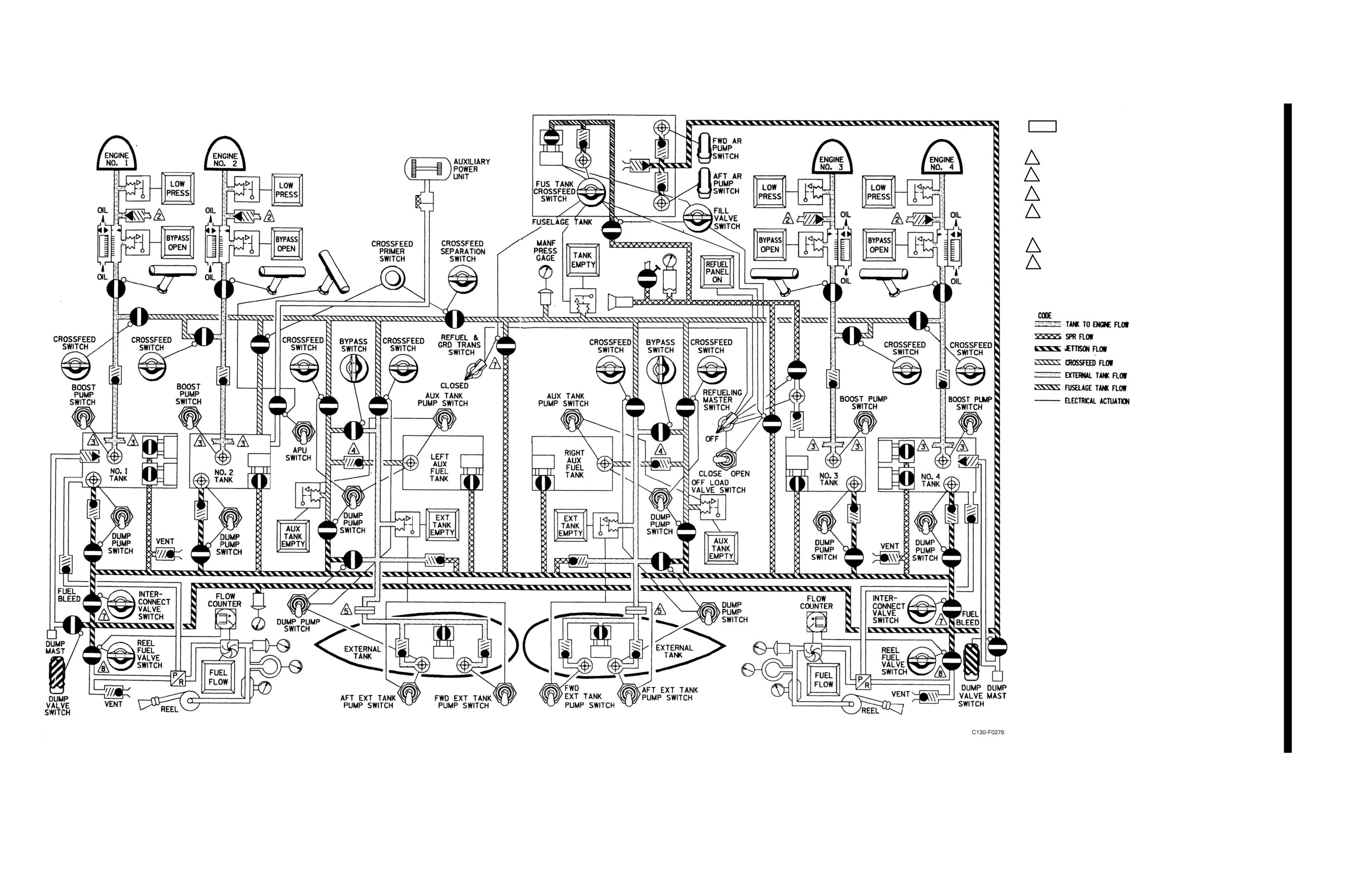
NAVAIR 01-75GAL-1
NOTE
1
REFER TO STANDARD SYMBOLS FIGURE FOR IDENTIFICATION OF SYMBOLS.
2
OVERBOARD DRAIN LINE.
3
WATER REMOVAL SYSTEM.
4
FIXED OPEN WHEN EXTERNAL TANKS ARE NOT INSTALLED.
5
LINES CAPPED WHEN EXTERNAL TANKS ARE NOT INSTALLED.
6
REFUELING, DEFUELING AND INTERNAL FUEL TRANSFERS ARE POSSIBLE ONLY
AS GROUND OPERATIONS, EXCEPT INFLIGHT FUEL TRANSFER INTO FUSELAGE
TANK IS A NORMAL OPERATION.
7
BOTH INTERCONNECT VALVES WILL CLOSE AND THE GROUND TRANSFER VALVE.
8
REEL SUPPLY VALVE IS NORMALLY CONTROLLED AUTOMATICALLY BY
ENGAGEMENT OR DISENGAGEMENT OF RECEIVER AIRCRAFT PROBE IN REEL
DROGUE. FLIGHT ENGINEER HAS OVERRIDE CONTROL OF VALVE FOR
CHECKING PRESSURE OF OPERATION OR IN CASE OF AUTOMATIC SYSTEM
FAILURE. VALVE IS ALSO CONTROLLED BY FUEL COUNTER.
Fuel System
FO-1 (Reverse Blank)
ORIGINAL