HELICOPTER, ATTACK, AH-64D LONGBOW APACHE. TECHNICAL MANUAL (2002) - page 15
TM 1-1520-251-10
CRUISE
CRUISE
AH64D
PRESSURE ALTITUDE 2000 FEET
T700GE701C
101% NR RPM, 8 HELLFIRE CONFIGURATION, JP8 FUEL
FAT = 30°C
FAT = 20°C
INDICATED
AIRSPEED
TOTAL FUEL FLOW LB/HOUR
TOTAL FUEL FLOW LB/HOUR
KNOTS
700
900
1100
1300
700
900
1100
1300
170
160
∆ Q %
∆ Q %
170
∆ F = 10.0 SQ FT
∆ F = 10.0 SQ FT
0
10
20
0
10
20
160
160
150
150
150
140
140
140
130
130
130
120
120
120
MAX
MAX
110
RANGE
RANGE
110
110
100
100
100
90
90
90
80
80
MAX
R/C
MAX
80
OR
R/C
70
70
OR
MAX
END
MAX
70
END
60
60
60
50
50
50
40
40
40
30
30
30
20
20
20
10
0
30
40
50
60
70
80
90
100
30
40
50
60
70
80
90
100
INDICATED TORQUE PER ENGINE %
INDICATED TORQUE PER ENGINE %
DATA BASIS: DERIVED FROM FLIGHT TEST AND ENGINE MODEL SPEC NO. E1290, 15 APRIL 1988
LBA0204
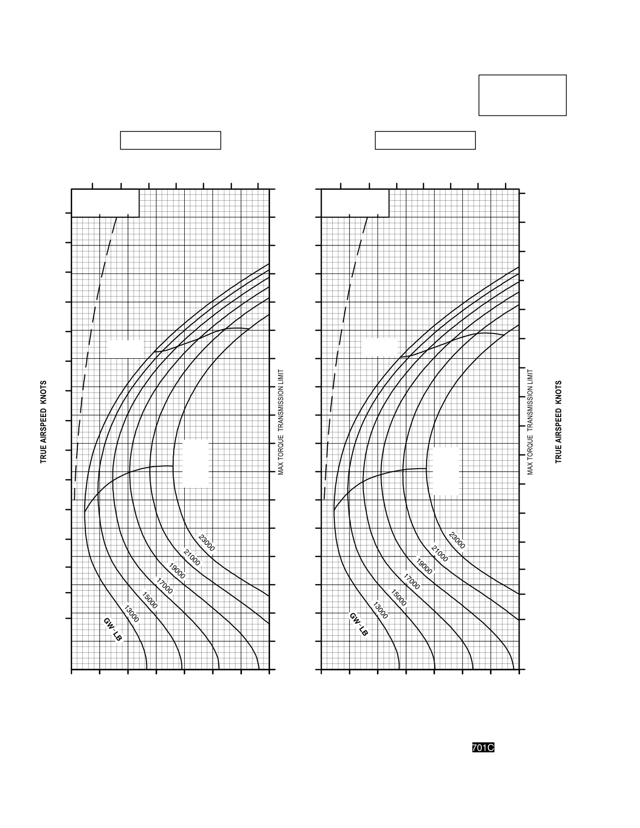
Figure 7A-20. Cruise Chart, 2,000 Feet, - 30°C and - 20°C (sheet 2 of 6)
Use or disclosure of this information is subject to the restriction(s) on the title page of this document.
7A-32
TM 1-1520-251-10
CRUISE
CRUISE
AH64D
PRESSURE ALTITUDE 2000 FEET
T700GE701C
101% NR RPM, 8 HELLFIRE CONFIGURATION, JP8 FUEL
FAT = 10°C
FAT = 0°C
INDICATED
AIRSPEED
TOTAL FUEL FLOW LB/HOUR
TOTAL FUEL FLOW LB/HOUR
KNOTS
700
900
1100
1300
700
900
1100
1300
170
∆ Q %
∆ Q %
170
∆ F = 10.0 SQ FT
∆ F = 10.0 SQ FT
0
10
20
0
10
20
170
160
160
160
150
150
150
140
140
140
130
130
130
120
MAX
120
RANGE
MAX
120
110
RANGE
110
110
100
100
100
90
90
90
80
MAX
MAX
80
R/C
R/C
80
70
OR
OR
MAX
MAX
70
70
END
END
60
60
60
50
50
50
40
40
40
30
30
30
20
20
20
10
0
30
40
50
60
70
80
90
100
30
40
50
60
70
80
90
100
INDICATED TORQUE PER ENGINE %
INDICATED TORQUE PER ENGINE %
DATA BASIS: DERIVED FROM FLIGHT TEST AND ENGINE MODEL SPEC NO. E1290, 15 APRIL 1988
LBA0205
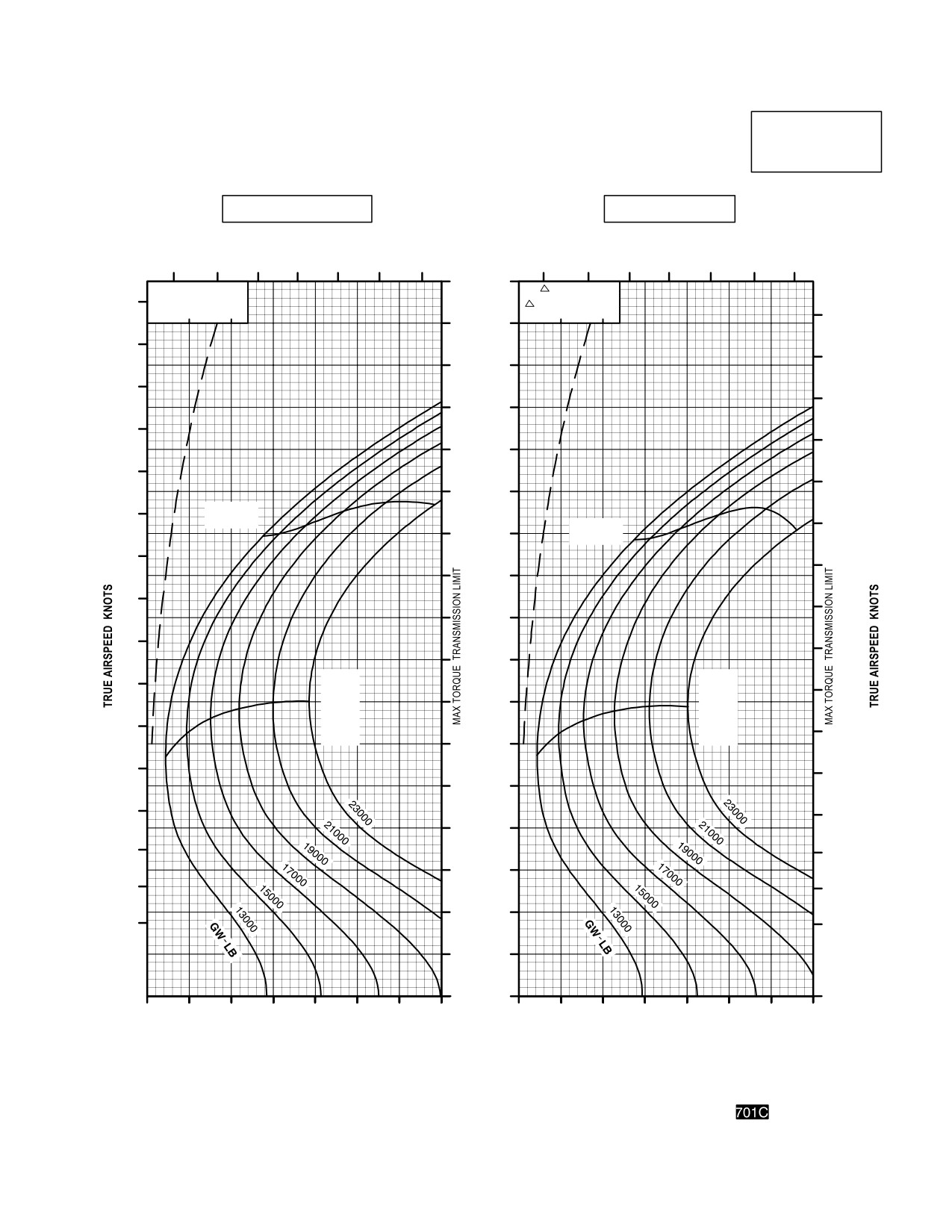
Figure 7A-20. Cruise Chart, 2,000 Feet, - 10°C and 0°C (sheet 3 of 6)
Use or disclosure of this information is subject to the restriction(s) on the title page of this document.
7A-33
TM 1-1520-251-10
CRUISE
CRUISE
PRESSURE ALTITUDE 2000 FEET
AH64D
T700GE701C
101% NR RPM, 8 HELLFIRE CONFIGURATION, JP8 FUEL
FAT = +10°C
FAT = +20°C
INDICATED
TOTAL FUEL FLOW LB/HOUR
AIRSPEED
TOTAL FUEL FLOW LB/HOUR
KNOTS
700
900
1100
1300
700
900
1100
1300
170
180
∆ Q %
∆ Q %
180
∆ F = 10.0 SQ FT
∆ F = 10.0 SQ FT
0
10
20
0
10
20
160
170
170
150
160
160
150
140
150
140
130
140
130
120
130
120
MAX
110
MAX
120
RANGE
RANGE
110
100
110
100
90
100
90
80
90
MAX
80
MAX
R/C
70
80
R/C
OR
OR
MAX
70
MAX
END
60
70
END
60
60
50
50
50
40
40
40
30
30
30
20
20
20
10
0
30
40
50
60
70
80
90
100
30
40
50
60
70
80
90
100
INDICATED TORQUE PER ENGINE %
INDICATED TORQUE PER ENGINE %
DATA BASIS: DERIVED FROM FLIGHT TEST AND ENGINE MODEL SPEC NO. E1290, 15 APRIL 1988
LBA0206
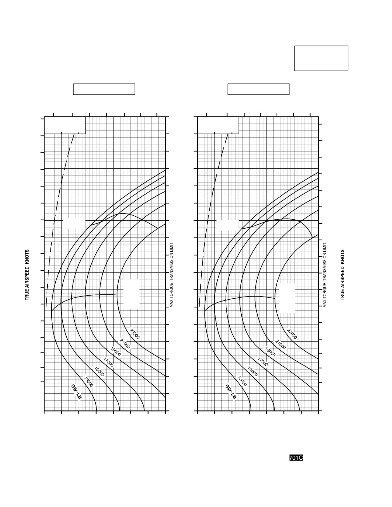
Figure 7A-20. Cruise Chart, 2,000 Feet, +10°C and +20°C (sheet 4 of 6)
Use or disclosure of this information is subject to the restriction(s) on the title page of this document.
7A-34
TM 1-1520-251-10
CRUISE
CRUISE
AH64D
PRESSURE ALTITUDE 2000 FEET
T700GE701C
101% NR RPM, 8 HELLFIRE CONFIGURATION, JP8 FUEL
FAT = +30°C
FAT = +40°C
INDICATED
TOTAL FUEL FLOW LB/HOUR
AIRSPEED
TOTAL FUEL FLOW LB/HOUR
KNOTS
700
900
1100
1300
700
900
1100
1300
170
∆ Q %
∆ Q %
∆ F = 10.0 SQ FT
∆ F = 10.0 SQ FT
180
0
10
20
0
10
20
160
180
170
170
150
160
160
140
150
150
130
140
140
120
130
130
110
120
MAX
120
RANGE
MAX
100
RANGE
110
110
90
100
100
80
90
90
80
70
MAX
80
MAX
R/C
R/C
OR
70
60
OR
MAX
70
MAX
END
END
60
50
60
50
40
50
40
40
30
30
30
20
20
20
10
0
30
40
50
60
70
80
90
100
30
40
50
60
70
80
90
100
INDICATED TORQUE PER ENGINE %
INDICATED TORQUE PER ENGINE %
DATA BASIS: DERIVED FROM FLIGHT TEST AND ENGINE MODEL SPEC NO. E1290, 15 APRIL 1988
LBA0207
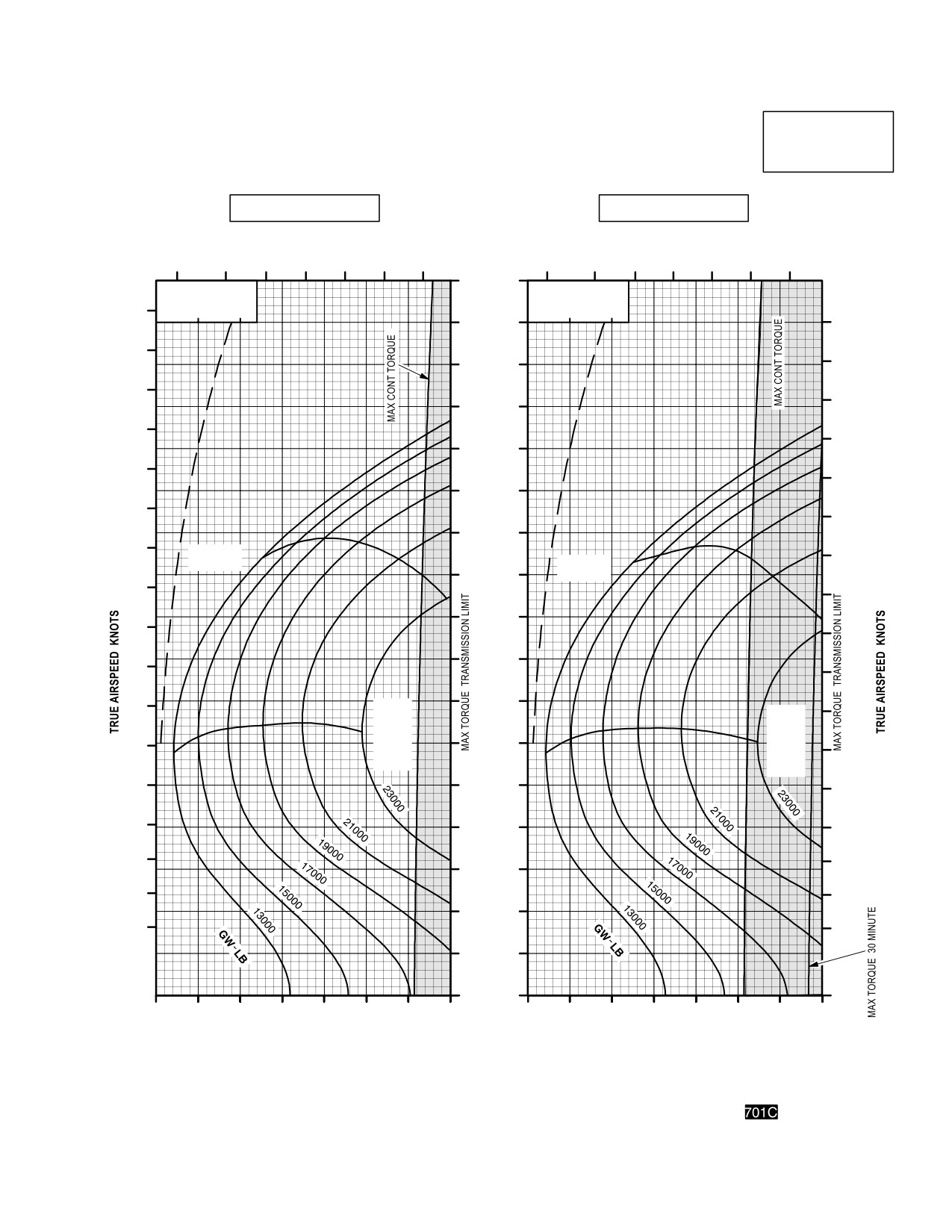
Figure 7A-20. Cruise Chart, 2,000 Feet, +30°C and +40°C (sheet 5 of 6)
Use or disclosure of this information is subject to the restriction(s) on the title page of this document.
7A-35
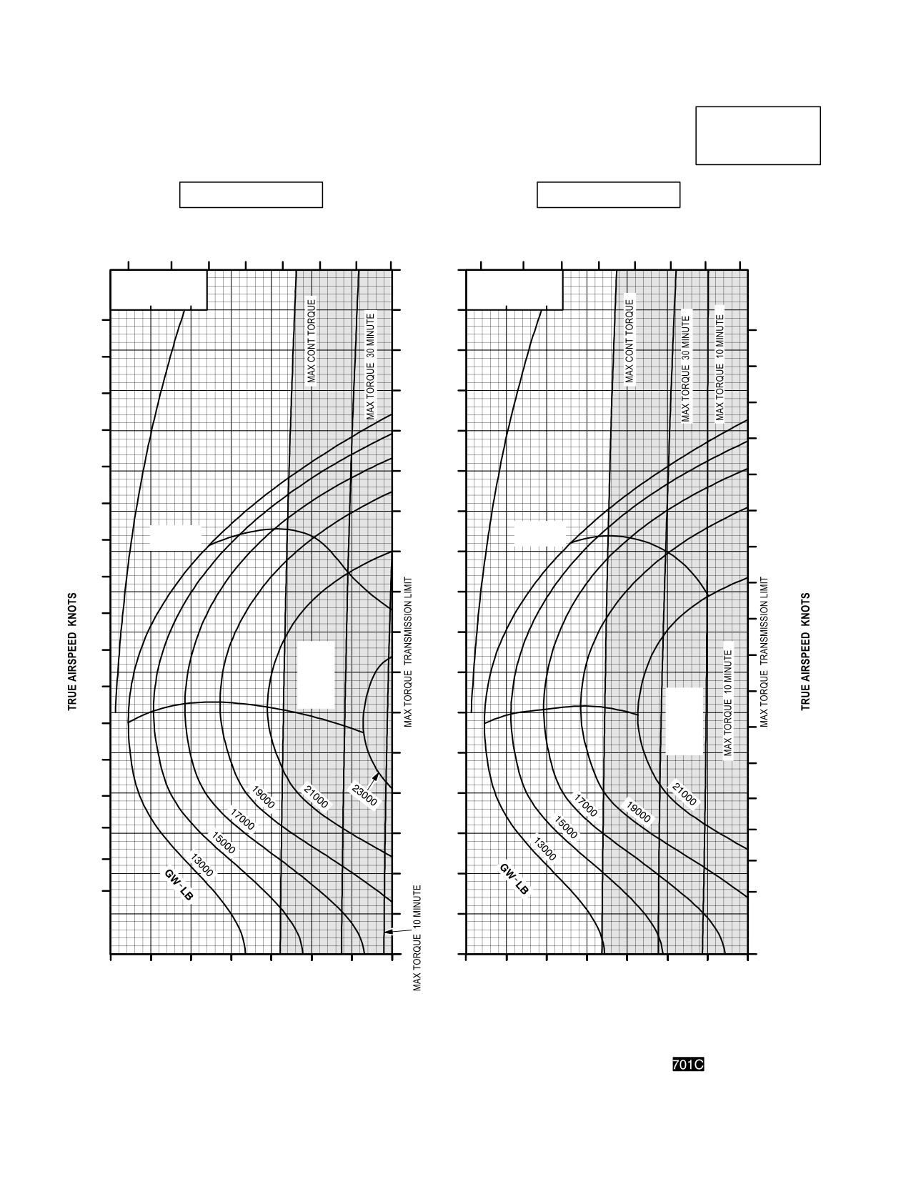
TM 1-1520-251-10
CRUISE
CRUISE
AH64D
PRESSURE ALTITUDE 2000 FEET
T700GE701C
101% NR RPM, 8 HELLFIRE CONFIGURATION, JP8 FUEL
FAT = +50°C
FAT = +60°C
INDICATED
TOTAL FUEL FLOW LB/HOUR
AIRSPEED
TOTAL FUEL FLOW LB/HOUR
KNOTS
700
900
1100
1300
700
900
1100
1300
170
∆ Q %
∆ Q %
∆ F = 10.0 SQ FT
∆ F = 10.0 SQ FT
0
10
20
0
10
20
160
180
180
150
170
170
160
140
160
150
130
150
140
120
140
130
110
130
MAX
MAX
120
RANGE
RANGE
120
100
110
110
90
100
100
80
90
MAX
90
R/C
70
OR
80
MAX
80
MAX
END
60
R/C
70
OR
70
MAX
50
END
60
60
50
40
50
40
40
30
30
30
20
20
20
10
0
30
40
50
60
70
80
90
100
30
40
50
60
70
80
90
100
INDICATED TORQUE PER ENGINE %
INDICATED TORQUE PER ENGINE %
DATA BASIS: DERIVED FROM FLIGHT TEST AND ENGINE MODEL SPEC NO. E1290, 15 APRIL 1988
LBA0208
Figure 7A-20. Cruise Chart, 2,000 Feet, +50°C and +60°C (sheet 6 of 6)
Use or disclosure of this information is subject to the restriction(s) on the title page of this document.
7A-36
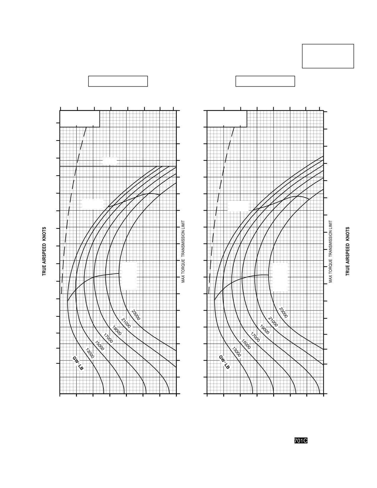
TM 1-1520-251-10
CRUISE
CRUISE
AH64D
PRESSURE ALTITUDE 4000 FEET
T700GE701C
101% NR RPM, 8 HELLFIRE CONFIGURATION, JP8 FUEL
FAT = 50 °C
FAT = 40 °C
INDICATED
TOTAL FUEL FLOW LB/HOUR
TOTAL FUEL FLOW LB/HOUR
AIRSPEED
600
800
1000
1200
KNOTS
700
900
1100
1300
170
170
∆ Q %
∆ Q %
∆ F = 10.0 SQ FT
∆ F = 10.0 SQ FT
160
0
10
20
0
10
20
160
160
150
150
150
140
V
140
NE
140
130
130
130
120
120
120
MAX
MAX
RANGE
RANGE
110
110
110
100
100
100
90
90
90
80
80
MAX
MAX
80
R/C
R/C
OR
70
OR
70
MAX
MAX
70
END
END
60
60
60
50
50
50
40
40
40
30
30
30
20
20
20
10
0
30
40
50
60
70
80
90
100
30
40
50
60
70
80
90
100
INDICATED TORQUE PER ENGINE %
INDICATED TORQUE PER ENGINE %
DATA BASIS: DERIVED FROM FLIGHT TEST AND ENGINE MODEL SPEC NO. E1290, 15 APRIL 1988
LBA0243
Figure 7A-21. Cruise Chart, 4,000 Feet, - 50°C and - 40°C (sheet 1 of 6)
Use or disclosure of this information is subject to the restriction(s) on the title page of this document.
7A-37
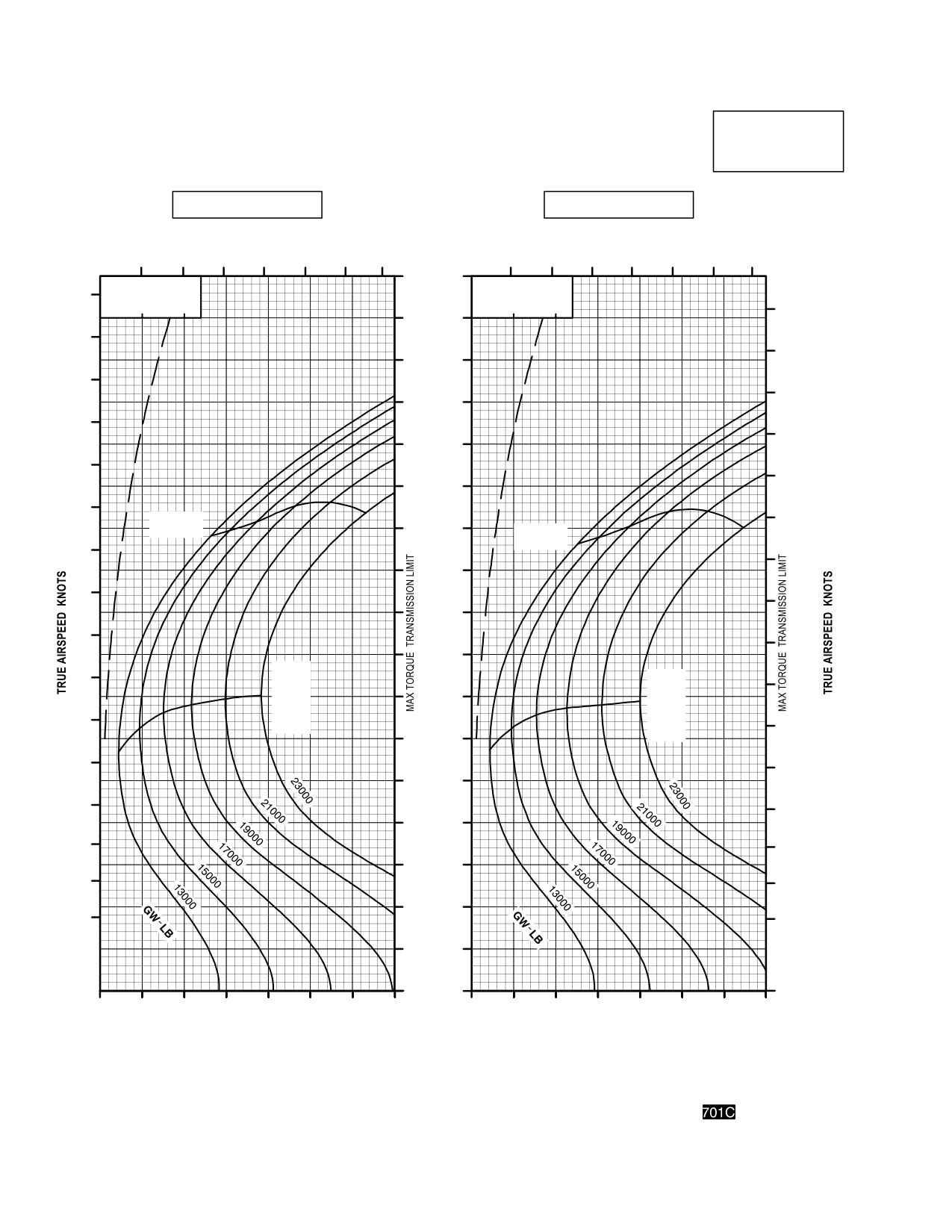
TM 1-1520-251-10
CRUISE
CRUISE
AH64D
PRESSURE ALTITUDE 4000 FEET
T700GE701C
101% NR RPM, 8 HELLFIRE CONFIGURATION, JP8 FUEL
FAT = 30 °C
FAT = 20 °C
TOTAL FUEL FLOW LB/HOUR
INDICATED
TOTAL FUEL FLOW LB/HOUR
AIRSPEED
700
900
1100
1300
KNOTS
700
900
1100
1300
170
∆ Q %
∆ Q %
170
∆ F = 10.0 SQ FT
∆ F = 10.0 SQ FT
0
10
20
0
10
20
170
160
160
160
150
150
150
140
140
140
130
130
130
120
120
MAX
120
RANGE
110
MAX
RANGE
110
110
100
100
100
90
90
90
80
MAX
80
MAX
R/C
80
70
R/C
OR
OR
MAX
70
MAX
END
70
60
END
60
60
50
50
50
40
40
40
30
30
30
20
20
20
10
0
30
40
50
60
70
80
90
100
30
40
50
60
70
80
90
100
INDICATED TORQUE PER ENGINE %
INDICATED TORQUE PER ENGINE %
DATA BASIS: DERIVED FROM FLIGHT TEST AND ENGINE MODEL SPEC NO. E1290, 15 APRIL 1988
LBA0209
Figure 7A-21. Cruise Chart, 4,000 Feet, - 30°C and - 20°C (sheet 2 of 6)
Use or disclosure of this information is subject to the restriction(s) on the title page of this document.
7A-38
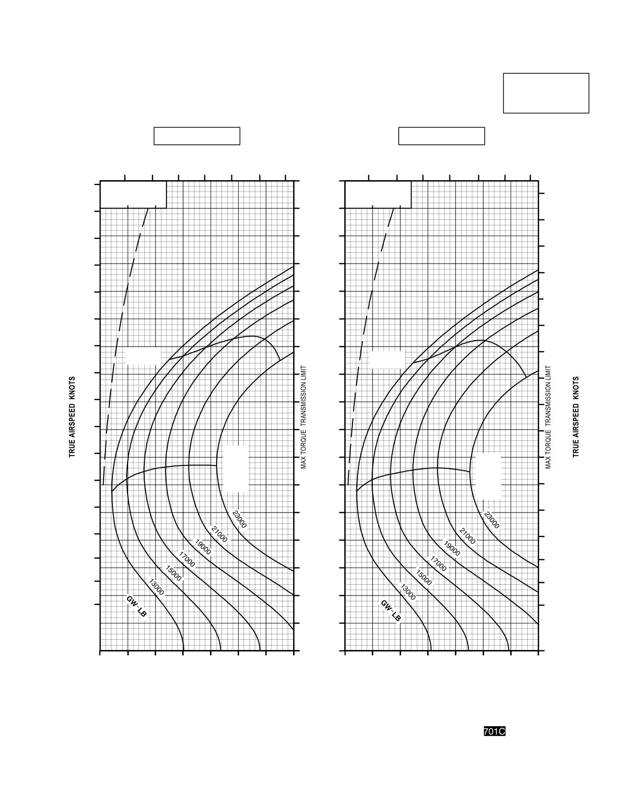
TM 1-1520-251-10
CRUISE
CRUISE
AH64D
PRESSURE ALTITUDE 4000 FEET
T700GE701C
101% NR RPM, 8 HELLFIRE CONFIGURATION, JP8 FUEL
FAT = 10° C
FAT = 0° C
INDICATED
TOTAL FUEL FLOW LB/HOUR
TOTAL FUEL FLOW LB/HOUR
AIRSPEED
700
900
1100
1300
KNOTS
700
900
1100
1300
170
180
∆ Q %
∆ Q %
180
∆ F = 10.0 SQ FT
∆ F = 10.0 SQ FT
0
10
20
0
10
20
160
170
170
160
150
160
150
140
150
140
130
140
130
120
130
120
110
MAX
120
MAX
RANGE
RANGE
110
100
110
100
90
100
90
80
90
80
MAX
70
80
R/C
MAX
OR
R/C
70
MAX
OR
60
70
END
MAX
END
60
60
50
50
50
40
40
40
30
30
30
20
20
20
10
0
30
40
50
60
70
80
90
100
30
40
50
60
70
80
90
100
INDICATED TORQUE PER ENGINE %
INDICATED TORQUE PER ENGINE %
DATA BASIS: DERIVED FROM FLIGHT TEST AND ENGINE MODEL SPEC NO. E1290, 15 APRIL 1988
LBA0210
Figure 7A-21. Cruise Chart, 4,000 Feet, - 10°C and 0°C (sheet 3 of 6)
Use or disclosure of this information is subject to the restriction(s) on the title page of this document.
7A-39
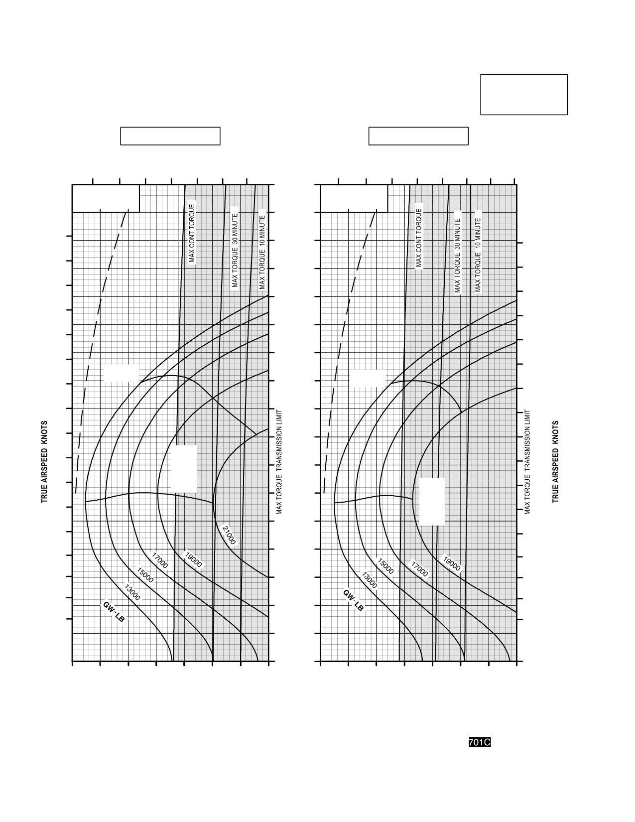
TM 1-1520-251-10
CRUISE
CRUISE
PRESSURE ALTITUDE 4000 FEET
AH64D
T700GE701C
101% NR RPM, 8 HELLFIRE CONFIGURATION, JP8 FUEL
FAT = +10° C
FAT = +20° C
TOTAL FUEL FLOW LB/HOUR
INDICATED
TOTAL FUEL FLOW LB/HOUR
AIRSPEED
700
900
1100
1300
700
900
1100
1300
KNOTS
170
∆ Q %
∆ Q %
∆ F = 10.0 SQ FT
∆ F = 10.0 SQ FT
180
180
0
10
20
0
10
20
160
170
170
150
160
160
140
150
150
130
140
140
120
130
130
110
MAX
120
120
RANGE
MAX
RANGE
100
110
110
90
100
100
80
90
90
MAX
R/C
70
OR
80
MAX
80
MAX
R/C
END
OR
70
60
MAX
70
END
60
50
60
50
40
50
40
40
30
30
30
20
20
20
10
0
30
40
50
60
70
80
90
100
30
40
50
60
70
80
90
100
INDICATED TORQUE PER ENGINE %
INDICATED TORQUE PER ENGINE %
DATA BASIS: DERIVED FROM FLIGHT TEST AND ENGINE MODEL SPEC NO. E1290, 15 APRIL 1988
LBA0211
Figure 7A-21. Cruise Chart, 4,000 Feet, +10°C and +20°C (sheet 4 of 6)
Use or disclosure of this information is subject to the restriction(s) on the title page of this document.
7A-40
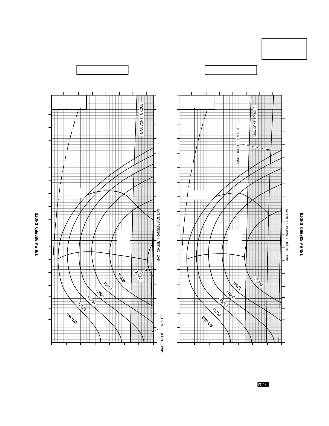
TM 1-1520-251-10
CRUISE
CRUISE
AH64D
PRESSURE ALTITUDE 4000 FEET
T700GE701C
101% NR RPM, 8 HELLFIRE CONFIGURATION, JP8 FUEL
FAT = +30° C
FAT = +40° C
TOTAL FUEL FLOW LB/HOUR
INDICATED
TOTAL FUEL FLOW LB/HOUR
AIRSPEED
700
900
1100
1300
KNOTS
700
900
1100
1300
170
∆ Q %
∆ Q %
∆ F = 10.0 SQ FT
∆ F = 10.0 SQ FT
0
10
20
0
10
20
160
180
180
150
170
170
140
160
160
150
130
150
140
120
140
130
110
130
MAX
120
MAX
RANGE
120
100
RANGE
110
110
90
100
100
80
90
MAX
MAX
90
R/C
R/C
70
OR
OR
80
MAX
MAX
80
END
END
60
70
70
50
60
60
50
40
50
40
40
30
30
30
20
20
20
10
0
30
40
50
60
70
80
90
100
30
40
50
60
70
80
90
100
INDICATED TORQUE PER ENGINE %
INDICATED TORQUE PER ENGINE %
DATA BASIS: DERIVED FROM FLIGHT TEST AND ENGINE MODEL SPEC NO. E1290, 15 APRIL 1988
LBA0212
Figure 7A-21. Cruise Chart, 4,000 Feet, +30°C and +40°C (sheet 5 of 6)
Use or disclosure of this information is subject to the restriction(s) on the title page of this document.
7A-41
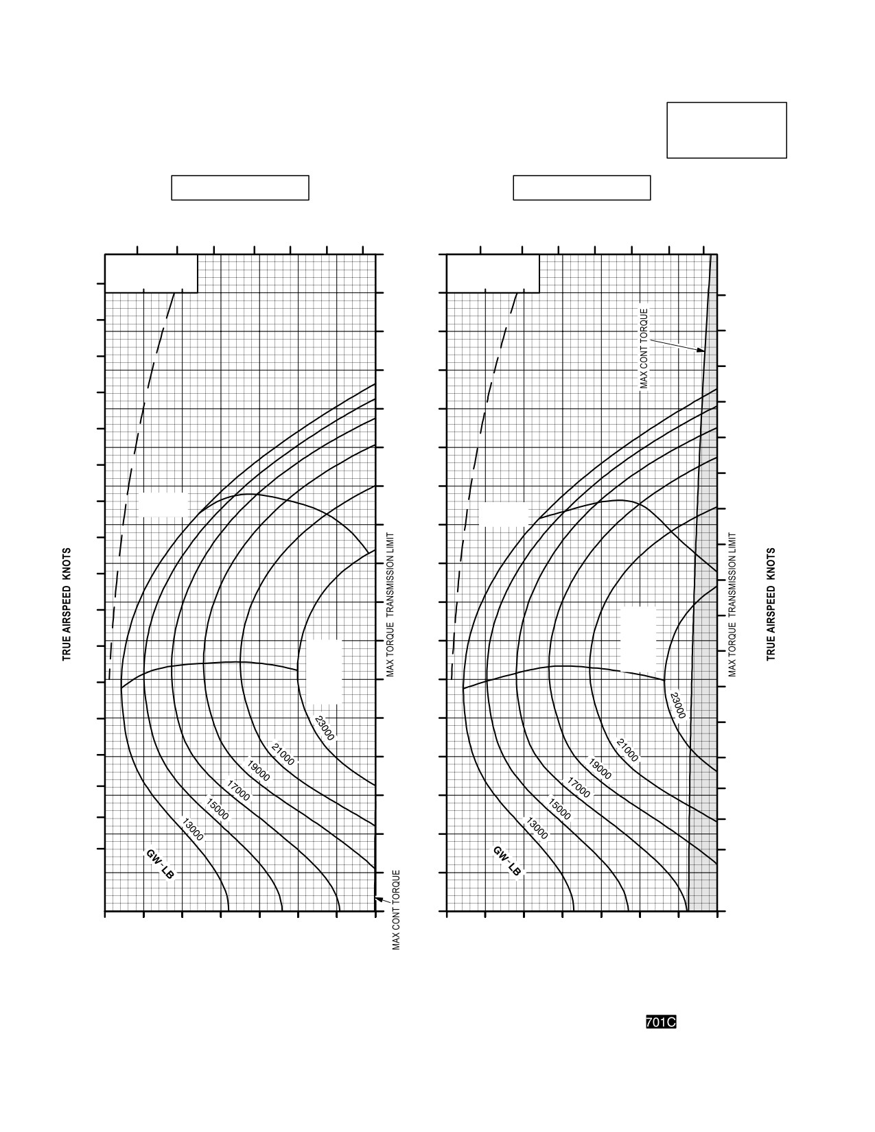
TM 1-1520-251-10
CRUISE
CRUISE
AH64D
PRESSURE ALTITUDE 4000 FEET
T700GE701C
101% NR RPM, 8 HELLFIRE CONFIGURATION, JP8 FUEL
FAT = +50 °C
FAT = +60 °C
INDICATED
TOTAL FUEL FLOW LB/HOUR
TOTAL FUEL FLOW LB/HOUR
AIRSPEED
700
900
1100
1300
KNOTS
700
900
1100
1300
170
∆ Q %
∆ Q %
∆ F = 10.0 SQ FT
∆ F = 10.0 SQ FT
0
10
20
0
10
20
160
180
150
180
170
140
170
160
160
130
150
150
120
140
140
110
130
130
MAX
MAX
RANGE
100
120
RANGE
120
110
90
110
100
80
100
MAX
90
R/C
90
70
OR
80
MAX
MAX
80
END
60
R/C
OR
70
MAX
70
50
END
60
60
40
50
50
40
30
40
30
30
20
20
20
10
0
30
40
50
60
70
80
90
100
30
40
50
60
70
80
90
100
INDICATED TORQUE PER ENGINE %
INDICATED TORQUE PER ENGINE %
DATA BASIS: DERIVED FROM FLIGHT TEST AND ENGINE MODEL SPEC NO. E1290, 15 APRIL 1988
LBA0213
Figure 7A-21. Cruise Chart, 4,000 Feet, +50°C and +60°C (sheet 6 of 6)
Use or disclosure of this information is subject to the restriction(s) on the title page of this document.
7A-42
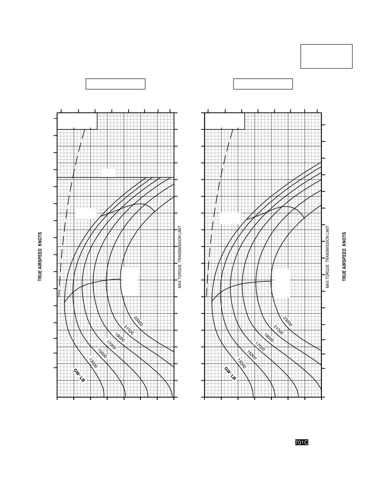
TM 1-1520-251-10
CRUISE
CRUISE
AH64D
PRESSURE ALTITUDE 6000 FEET
T700GE701C
101% NR RPM, 8 HELLFIRE CONFIGURATION, JP8 FUEL
FAT = 50° C
FAT = 40° C
TOTAL FUEL FLOW LB/HOUR
INDICATED
TOTAL FUEL FLOW LB/HOUR
AIRSPEED
600
800
1000
1200
KNOTS
600
800
1000
1200
170
∆ Q %
∆ Q %
170
∆ F = 10.0 SQ FT
∆ F = 10.0 SQ FT
0
10
20
0
10
20
170
160
160
160
150
150
150
140
140
V
NE
140
130
130
130
120
120
120
MAX
110
RANGE
MAX
110
RANGE
110
100
100
100
90
90
90
80
80
MAX
MAX
80
R/C
70
R/C
OR
OR
70
MAX
MAX
70
END
60
END
60
60
50
50
50
40
40
40
30
30
30
20
20
20
10
0
30
40
50
60
70
80
90
100
30
40
50
60
70
80
90
100
INDICATED TORQUE PER ENGINE %
INDICATED TORQUE PER ENGINE %
DATA BASIS: DERIVED FROM FLIGHT TEST AND ENGINE MODEL SPEC NO. E1290, 15 APRIL 1988
LBA0214
Figure 7A-22. Cruise Chart, 6,000 Feet, - 50°C and - 40°C (sheet 1 of 5)
Use or disclosure of this information is subject to the restriction(s) on the title page of this document.
7A-43
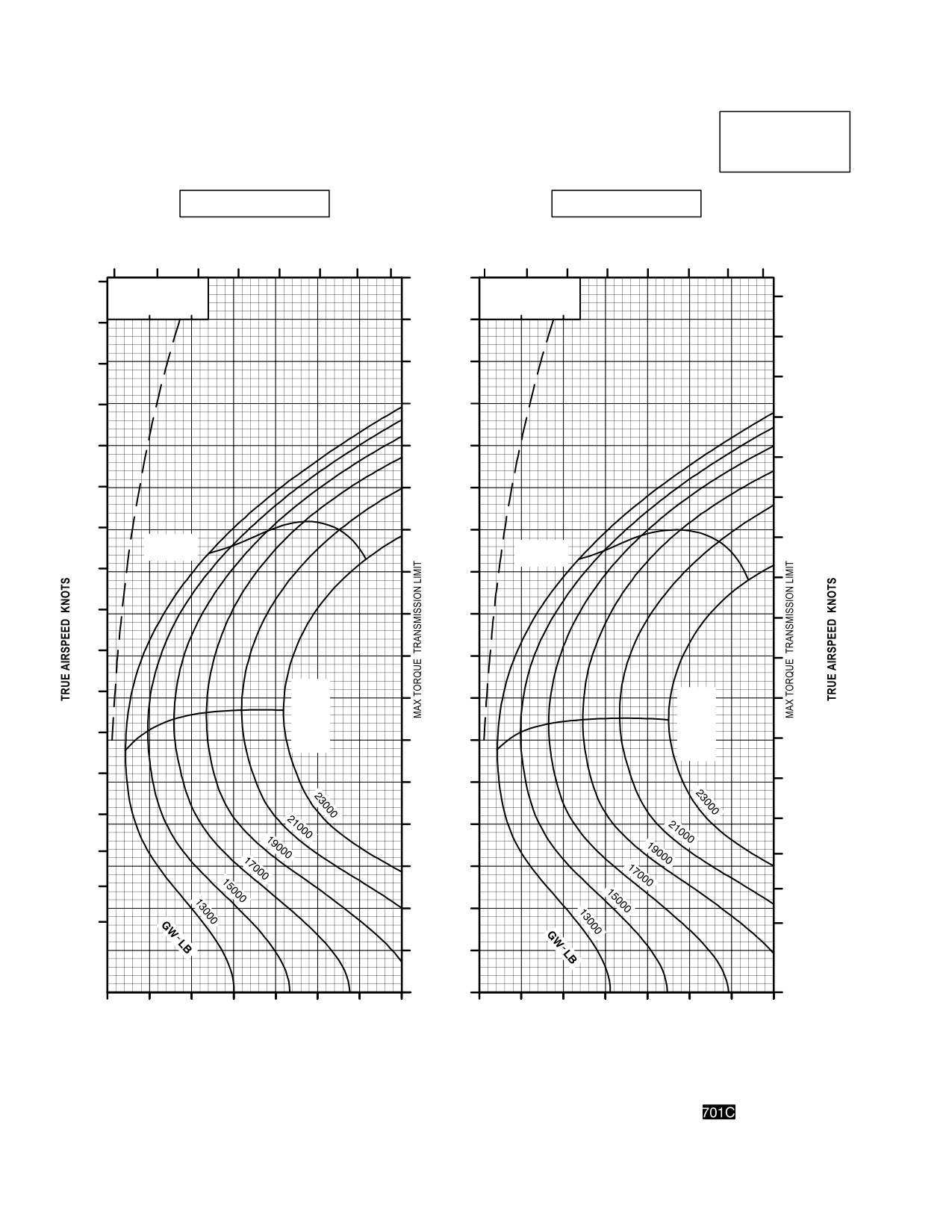
TM 1-1520-251-10
CRUISE
CRUISE
AH64D
PRESSURE ALTITUDE 6000 FEET
T700GE701C
101% NR RPM, 8 HELLFIRE CONFIGURATION, JP8 FUEL
FAT = 30° C
FAT = 20° C
INDICATED
TOTAL FUEL FLOW LB/HOUR
AIRSPEED
TOTAL FUEL FLOW LB/HOUR
KNOTS
600
800
1000
1200
600
800
1000
1200
170
180
∆ Q %
∆ Q %
∆ F = 10.0 SQ FT
∆ F = 10.0 SQ FT
180
0
10
20
0
10
20
160
170
170
160
150
160
150
140
150
140
130
140
130
120
130
120
110
120
MAX
MAX
RANGE
RANGE
110
100
110
100
90
100
90
80
90
80
MAX
70
MAX
80
R/C
R/C
OR
OR
70
MAX
60
MAX
70
END
END
60
60
50
50
50
40
40
40
30
30
30
20
20
20
10
0
30
40
50
60
70
80
90
100
30
40
50
60
70
80
90
100
INDICATED TORQUE PER ENGINE %
INDICATED TORQUE PER ENGINE %
DATA BASIS: DERIVED FROM FLIGHT TEST AND ENGINE MODEL SPEC NO. E1290, 15 APRIL 1988
LBA0215
Figure 7A-22. Cruise Chart, 6,000 Feet, - 30°C and - 20°C (sheet 2 of 5)
Use or disclosure of this information is subject to the restriction(s) on the title page of this document.
7A-44
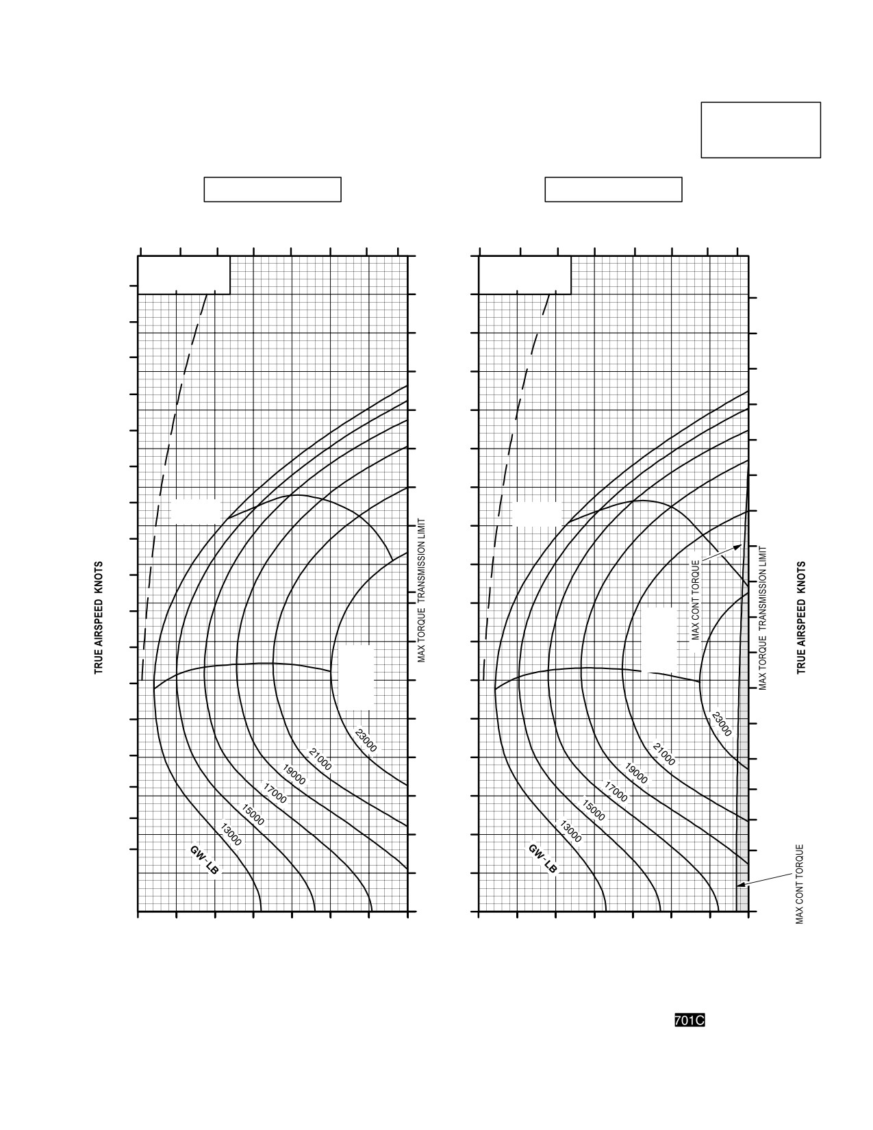
TM 1-1520-251-10
CRUISE
CRUISE
AH64D
PRESSURE ALTITUDE 6000 FEET
T700GE701C
101% NR RPM, 8 HELLFIRE CONFIGURATION, JP8 FUEL
FAT = 10 °C
FAT = 0 °C
INDICATED
TOTAL FUEL FLOW LB/HOUR
TOTAL FUEL FLOW LB/HOUR
AIRSPEED
KNOTS
600
800
1000
1200
600
800
1000
1200
170
∆ Q %
∆ Q %
∆ F = 10.0 SQ FT
∆ F = 10.0 SQ FT
180
0
10
20
0
10
20
160
180
170
150
170
160
140
160
150
150
130
140
140
120
130
130
110
120
MAX
MAX
120
RANGE
RANGE
100
110
110
90
100
100
80
90
MAX
90
R/C
70
OR
80
MAX
80
MAX
R/C
END
OR
60
70
MAX
70
END
60
50
60
50
40
50
40
40
30
30
30
20
20
20
10
0
30
40
50
60
70
80
90
100
30
40
50
60
70
80
90
100
INDICATED TORQUE PER ENGINE %
INDICATED TORQUE PER ENGINE %
DATA BASIS: DERIVED FROM FLIGHT TEST AND ENGINE MODEL SPEC NO. E1290, 15 APRIL 1988
LBA0216
Figure 7A-22. Cruise Chart, 6,000 Feet, - 10°C and 0°C (sheet 3 of 5)
Use or disclosure of this information is subject to the restriction(s) on the title page of this document.
7A-45
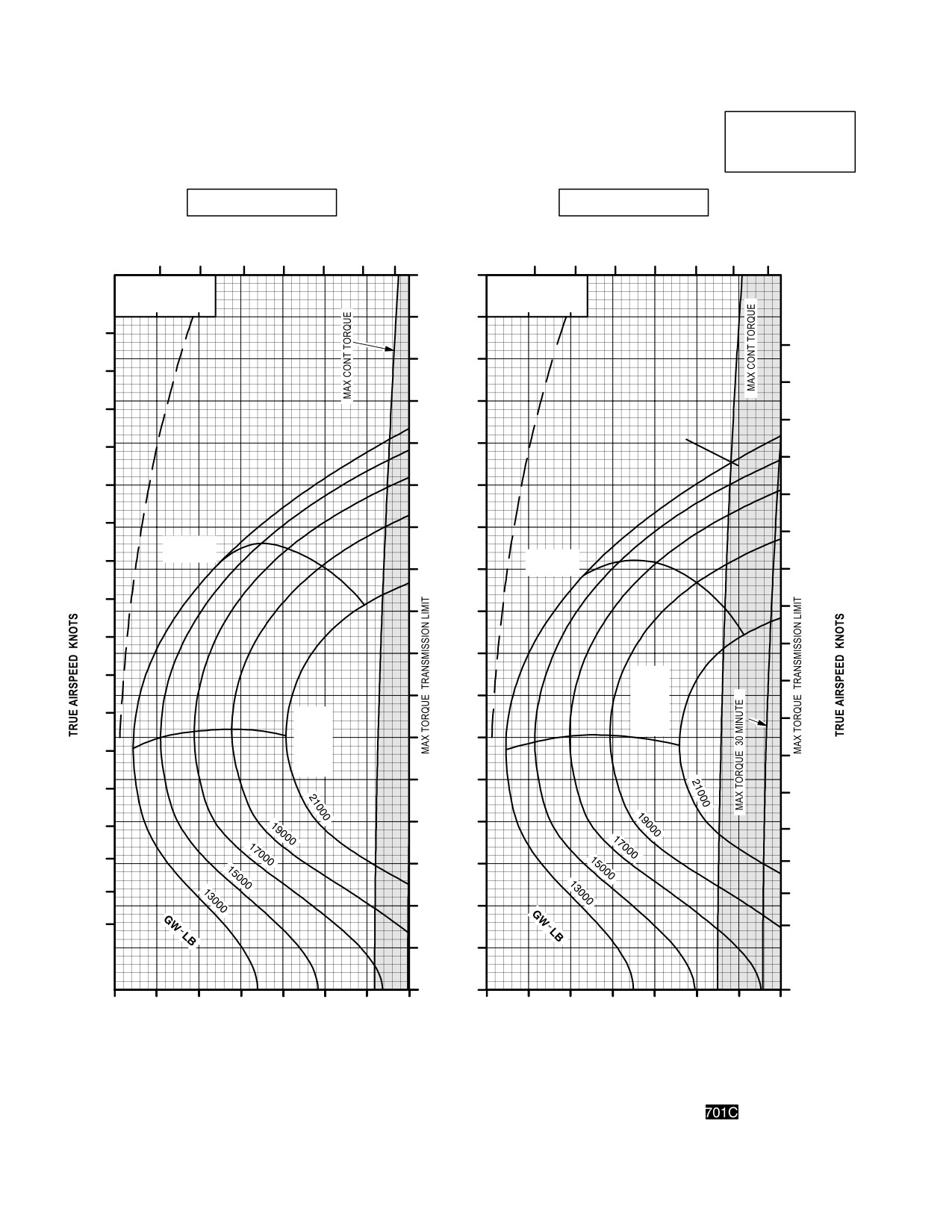
TM 1-1520-251-10
CRUISE
CRUISE
AH64D
PRESSURE ALTITUDE 6000 FEET
T700GE701C
101% NR RPM, 8 HELLFIRE CONFIGURATION, JP8 FUEL
FAT = +10 °C
FAT = +20 °C
TOTAL FUEL FLOW LB/HOUR
INDICATED
TOTAL FUEL FLOW LB/HOUR
AIRSPEED
700
900
1100
1300
KNOTS
700
900
1100
1300
170
∆ Q %
∆ Q %
∆ F = 10.0 SQ FT
∆ F = 10.0 SQ FT
0
10
20
0
10
20
160
180
180
150
170
170
140
160
160
150
130
150
140
120
140
130
110
130
MAX
RANGE
MAX
120
100
RANGE
120
110
110
90
100
100
80
90
MAX
90
R/C
70
OR
80
MAX
80
MAX
R/C
END
60
OR
70
MAX
70
END
50
60
60
50
40
50
40
40
30
30
30
20
20
20
10
0
30
40
50
60
70
80
90
100
30
40
50
60
70
80
90
100
INDICATED TORQUE PER ENGINE %
INDICATED TORQUE PER ENGINE %
DATA BASIS: DERIVED FROM FLIGHT TEST AND ENGINE MODEL SPEC NO. E1290, 15 APRIL 1988
LBA0217
Figure 7A-22. Cruise Chart, 6,000 Feet, +10°C and +20°C (sheet 4 of 5))
Use or disclosure of this information is subject to the restriction(s) on the title page of this document.
7A-46
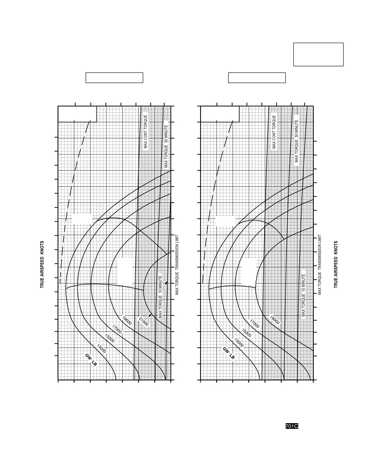
TM 1-1520-251-10
CRUISE
CRUISE
PRESSURE ALTITUDE 6000 FEET
AH64D
T700GE701C
101% NR RPM, 8 HELLFIRE CONFIGURATION, JP8 FUEL
FAT = +30° C
FAT = +40° C
INDICATED
TOTAL FUEL FLOW LB/HOUR
TOTAL FUEL FLOW LB/HOUR
AIRSPEED
700
900
1100
1300
KNOTS
700
900
1100
1300
170
∆ Q %
∆ Q %
∆ F = 10.0 SQ FT
∆ F = 10.0 SQ FT
0
10
20
0
10
20
160
180
150
180
170
140
170
160
160
130
150
150
120
140
140
110
130
130
MAX
100
MAX
120
RANGE
RANGE
120
110
90
110
100
80
100
MAX
MAX
90
90
R/C
70
R/C
OR
OR
80
MAX
MAX
80
END
60
END
70
70
50
60
60
40
50
50
40
30
40
30
30
20
20
20
10
0
30
40
50
60
70
80
90
100
30
40
50
60
70
80
90
100
INDICATED TORQUE PER ENGINE %
INDICATED TORQUE PER ENGINE %
DATA BASIS: DERIVED FROM FLIGHT TEST AND ENGINE MODEL SPEC NO. E1290, 15 APRIL 1988
LBA0218
Figure 7A-22. Cruise Chart, 6,000 Feet, +30°C and +40°C (sheet 5 of 5)
Use or disclosure of this information is subject to the restriction(s) on the title page of this document.
7A-47
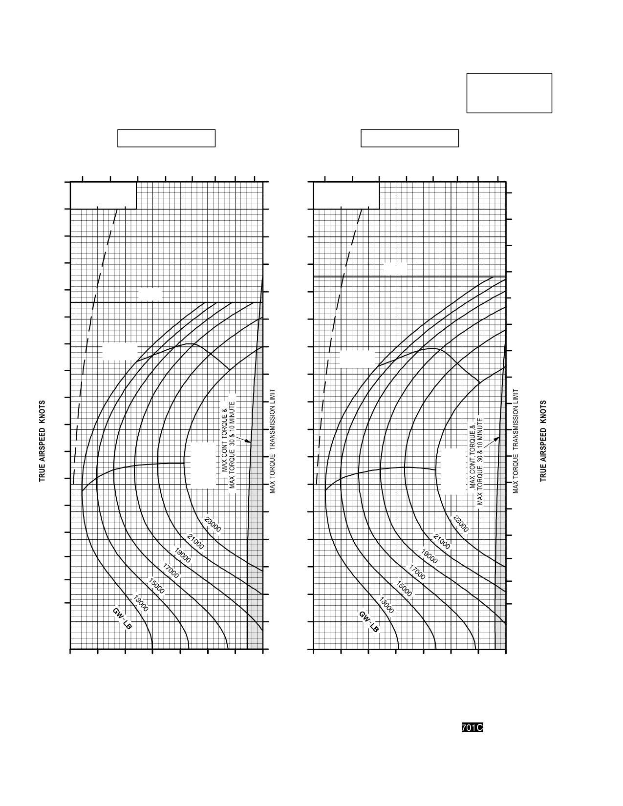
TM 1-1520-251-10
CRUISE
CRUISE
AH64D
PRESSURE ALTITUDE 8000 FEET
T700GE701C
101% NR RPM, 8 HELLFIRE CONFIGURATION, JP8 FUEL
FAT = 50 °C
FAT = 40 °C
TOTAL FUEL FLOW LB/HOUR
INDICATED
TOTAL FUEL FLOW LB/HOUR
AIRSPEED
600
800
1000
1200
600
800
1000
1200
KNOTS
180
170
∆ Q %
∆ Q %
180
∆ F = 10.0 SQ FT
∆ F = 10.0 SQ FT
0
10
20
0
10
20
170
160
170
160
150
160
150
140
V
NE
150
140
V
130
NE
140
130
120
130
120
MAX
110
120
RANGE
MAX
RANGE
110
100
110
100
90
100
90
80
90
80
MAX
70
MAX
80
R/C
R/C
OR
OR
70
MAX
60
MAX
70
END
END
60
60
50
50
50
40
40
40
30
30
30
20
20
20
10
0
30
40
50
60
70
80
90
100
30
40
50
60
70
80
90
100
INDICATED TORQUE PER ENGINE %
INDICATED TORQUE PER ENGINE %
DATA BASIS: DERIVED FROM FLIGHT TEST AND ENGINE MODEL SPEC NO. E1290, 15 APRIL 1988
LBA0219
Figure 7A-23. Cruise Chart, 8,000 Feet, - 50°C and - 40°C (sheet 1 of 5)
Use or disclosure of this information is subject to the restriction(s) on the title page of this document.
7A-48
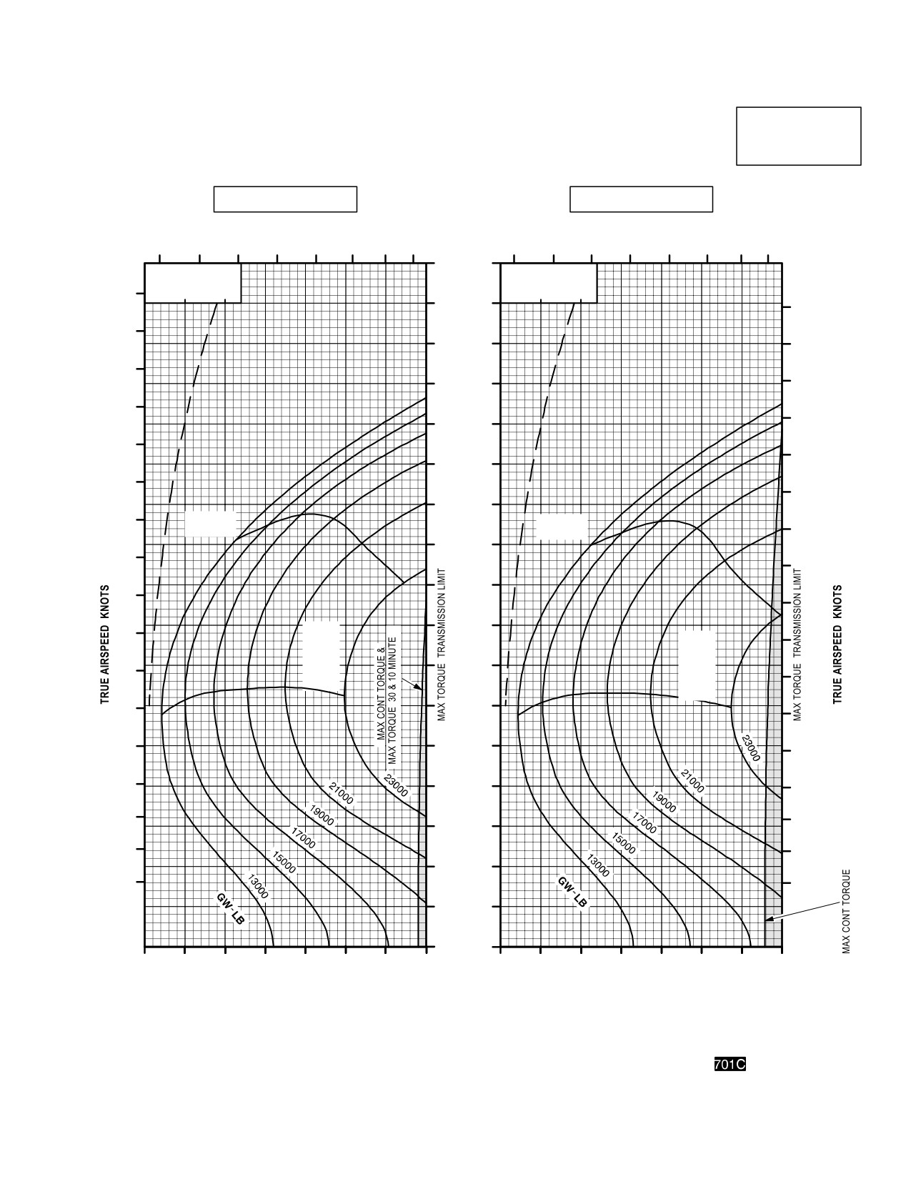
TM 1-1520-251-10
CRUISE
CRUISE
AH64D
PRESSURE ALTITUDE 8000 FEET
T700GE701C
101% NR RPM, 8 HELLFIRE CONFIGURATION, JP8 FUEL
FAT = 30° C
FAT = 20° C
INDICATED
TOTAL FUEL FLOW LB/HOUR
AIRSPEED
TOTAL FUEL FLOW LB/HOUR
600
800
1000
1200
KNOTS
600
800
1000
1200
170
∆ Q %
∆ Q %
∆ F = 10.0 SQ FT
∆ F = 10.0 SQ FT
180
0
10
20
0
10
20
160
180
170
150
170
160
160
140
150
150
130
140
140
120
130
130
110
120
MAX
MAX
RANGE
120
RANGE
100
110
110
90
100
100
80
90
MAX
MAX
90
R/C
R/C
OR
70
OR
80
MAX
80
MAX
END
END
70
60
70
60
50
60
50
40
50
40
40
30
30
30
20
20
20
10
0
30
40
50
60
70
80
90
100
30
40
50
60
70
80
90
100
INDICATED TORQUE PER ENGINE %
INDICATED TORQUE PER ENGINE %
DATA BASIS: DERIVED FROM FLIGHT TEST AND ENGINE MODEL SPEC NO. E1290, 15 APRIL 1988
LBA0220
Figure 7A-23. Cruise Chart, 8,000 Feet, - 30°C and - 20°C (sheet 2 of 5)
Use or disclosure of this information is subject to the restriction(s) on the title page of this document.
7A-49
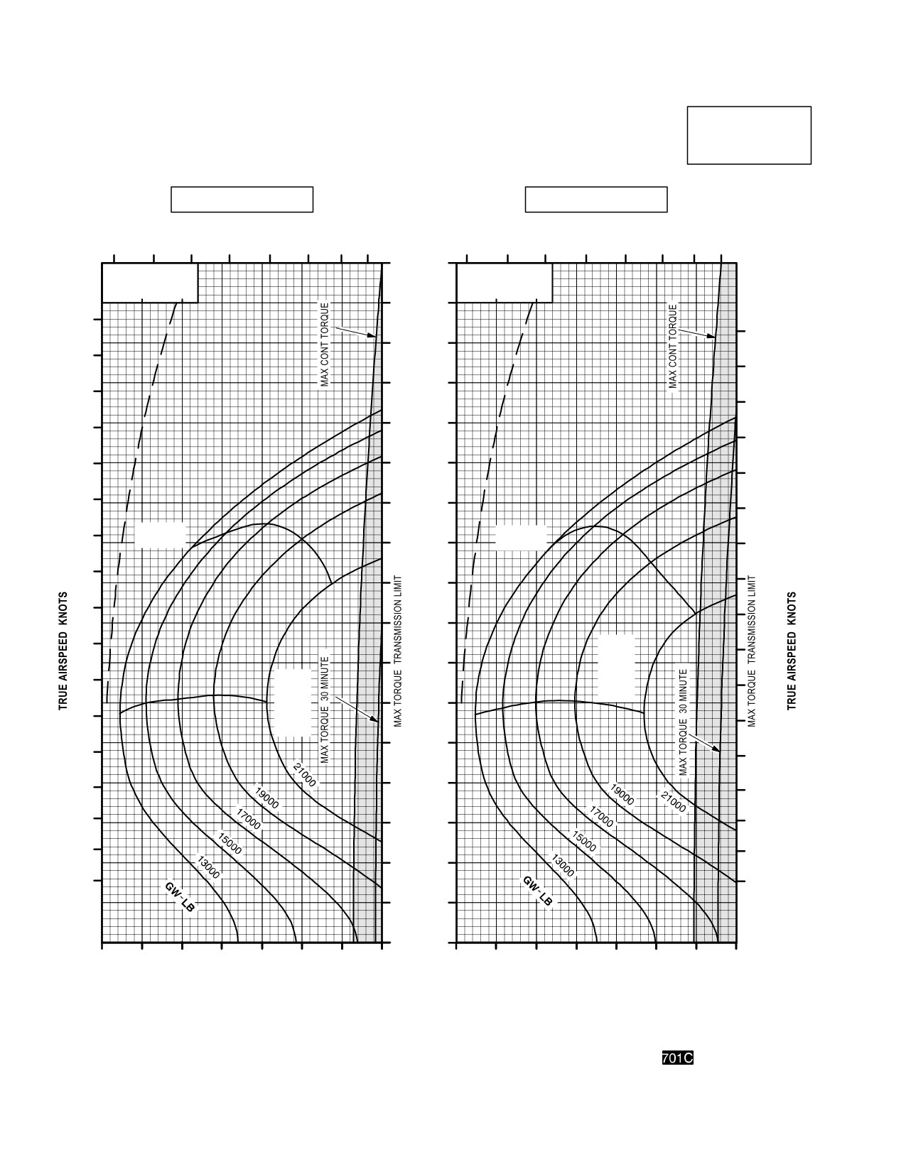
TM 1-1520-251-10
CRUISE
CRUISE
AH64D
PRESSURE ALTITUDE 8000 FEET
T700GE701C
101% NR RPM, 8 HELLFIRE CONFIGURATION, JP8 FUEL
FAT = 10 °C
FAT = 0 °C
INDICATED
TOTAL FUEL FLOW LB/HOUR
TOTAL FUEL FLOW LB/HOUR
AIRSPEED
600
800
1000
1200
KNOTS
600
800
1000
1200
170
∆ Q %
∆ Q %
∆ F = 10.0 SQ FT
∆ F = 10.0 SQ FT
0
10
20
0
10
20
160
180
180
150
170
170
140
160
160
150
130
150
140
120
140
130
110
130
MAX
MAX
120
RANGE
100
RANGE
120
110
90
110
100
100
80
90
MAX
90
R/C
70
OR
80
MAX
MAX
80
R/C
END
OR
60
70
MAX
70
END
50
60
60
50
40
50
40
40
30
30
30
20
20
20
10
0
30
40
50
60
70
80
90
100
30
40
50
60
70
80
90
100
INDICATED TORQUE PER ENGINE %
INDICATED TORQUE PER ENGINE %
DATA BASIS: DERIVED FROM FLIGHT TEST AND ENGINE MODEL SPEC NO. E1290, 15 APRIL 1988
LBA0221
Figure 7A-23. Cruise Chart, 8,000 Feet, - 10°C and 0°C (sheet 3 of 5)
Use or disclosure of this information is subject to the restriction(s) on the title page of this document.
7A-50
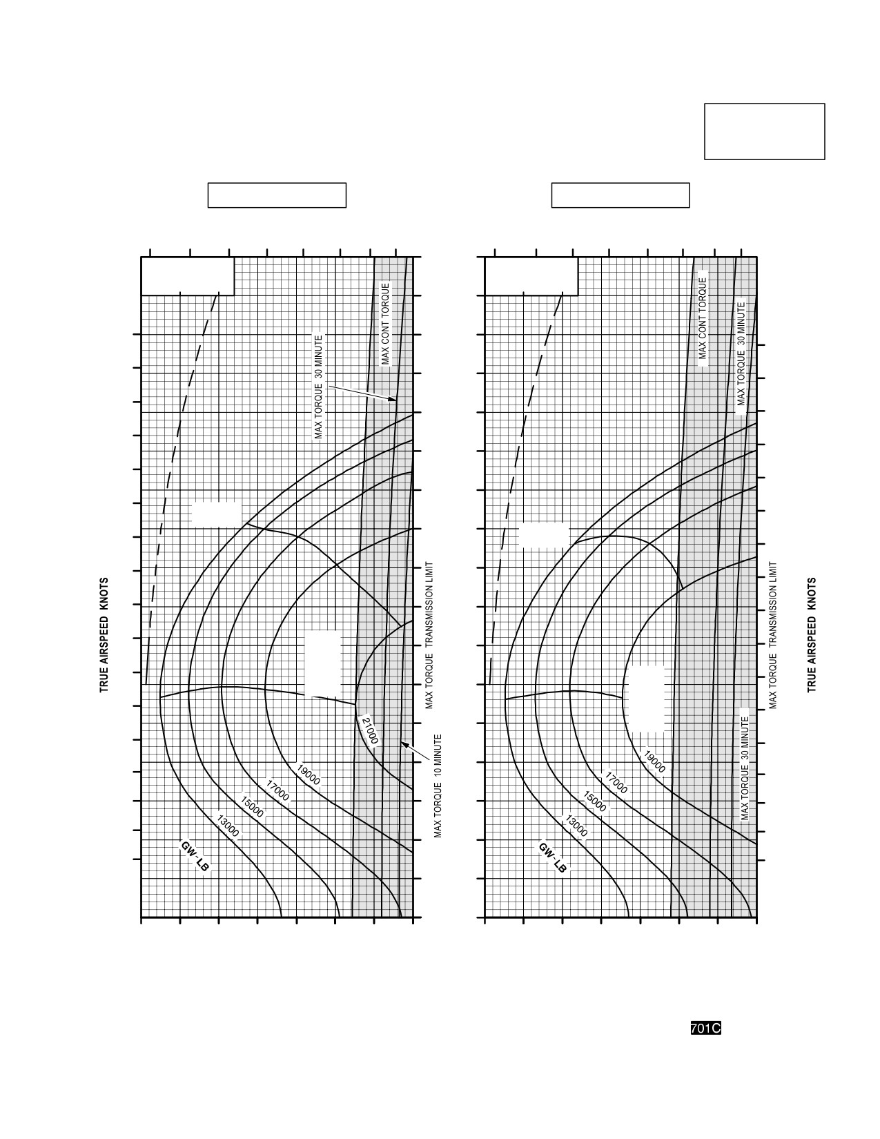
TM 1-1520-251-10
CRUISE
CRUISE
AH64D
PRESSURE ALTITUDE 8000 FEET
T700GE701C
101% NR RPM, 8 HELLFIRE CONFIGURATION, JP8 FUEL
FAT = +10° C
FAT = +20° C
INDICATED
TOTAL FUEL FLOW LB/HOUR
AIRSPEED
TOTAL FUEL FLOW LB/HOUR
KNOTS
600
800
1000
1200
600
800
1000
1200
170
∆ Q %
∆ Q %
∆ F = 10.0 SQ FT
∆ F = 10.0 SQ FT
0
10
20
0
10
20
160
180
150
180
170
140
170
160
130
160
150
150
120
140
140
110
130
MAX
130
RANGE
100
MAX
120
RANGE
120
110
90
110
100
80
100
90
MAX
70
90
R/C
OR
80
MAX
80
MAX
60
R/C
END
OR
70
70
MAX
50
END
60
60
40
50
50
40
30
40
30
30
20
20
20
10
0
30
40
50
60
70
80
90
100
30
40
50
60
70
80
90
100
INDICATED TORQUE PER ENGINE %
INDICATED TORQUE PER ENGINE %
DATA BASIS: DERIVED FROM FLIGHT TEST AND ENGINE MODEL SPEC NO. E1290, 15 APRIL 1988
LBA0222
Figure 7A-23. Cruise Chart, 8,000 Feet, +10°C and +20°C (sheet 4 of 5)
Use or disclosure of this information is subject to the restriction(s) on the title page of this document.
7A-51
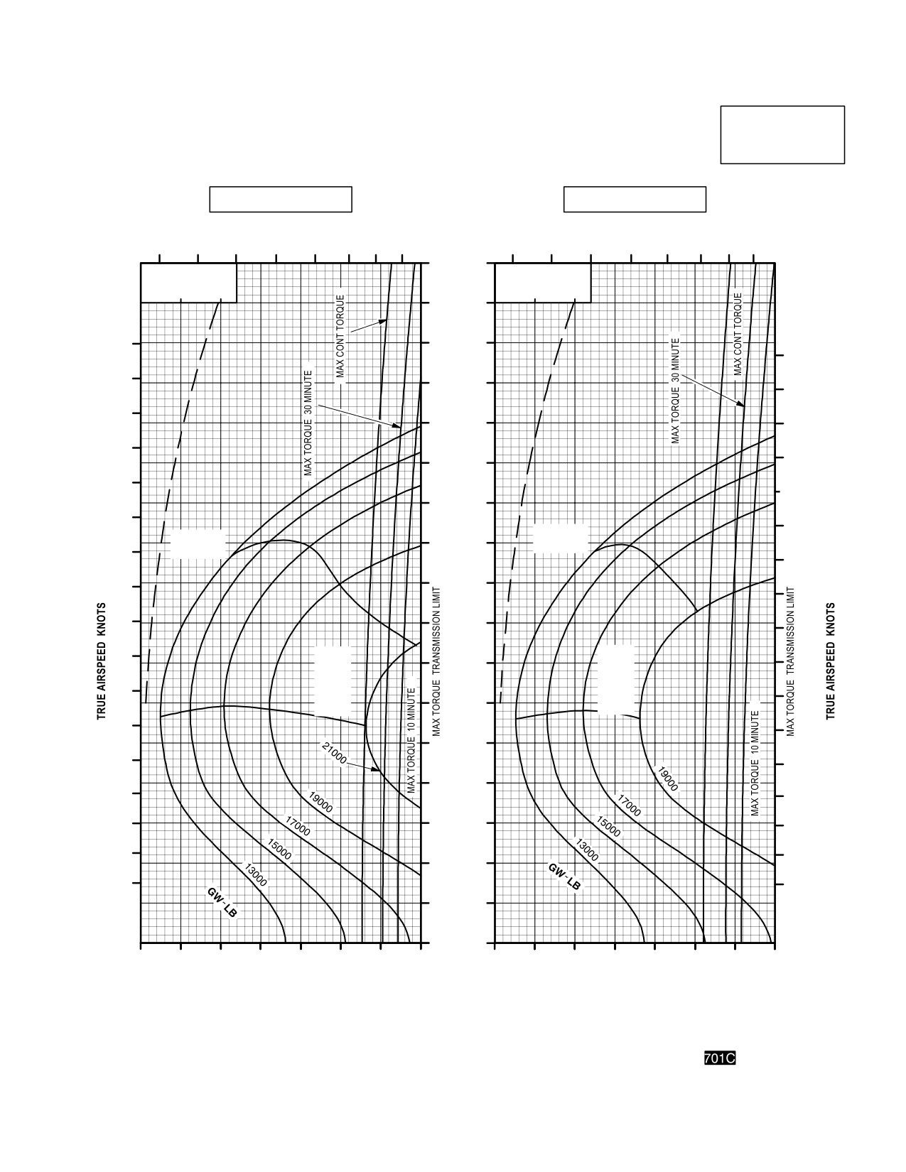
TM 1-1520-251-10
CRUISE
CRUISE
AH64D
PRESSURE ALTITUDE 8000 FEET
T700GE701C
101% NR RPM, 8 HELLFIRE CONFIGURATION, JP8 FUEL
FAT = +30° C
FAT = +40° C
TOTAL FUEL FLOW LB/HOUR
INDICATED
TOTAL FUEL FLOW LB/HOUR
AIRSPEED
600
800
1000
1200
KNOTS
600
800
1000
1200
170
∆ Q %
∆ Q %
∆ F = 10.0 SQ FT
∆ F = 10.0 SQ FT
0
10
20
0
10
20
160
150
180
180
140
170
170
130
160
160
150
120
150
140
110
140
130
130
MAX
100
MAX
RANGE
RANGE
120
120
90
110
110
80
100
100
MAX
90
70
MAX
R/C
90
R/C
OR
80
MAX
OR
60
80
MAX
END
END
70
70
50
60
60
40
50
50
40
30
40
30
30
20
20
20
10
0
30
40
50
60
70
80
90
100
30
40
50
60
70
80
90
100
INDICATED TORQUE PER ENGINE %
INDICATED TORQUE PER ENGINE %
DATA BASIS: DERIVED FROM FLIGHT TEST AND ENGINE MODEL SPEC NO. E1290, 15 APRIL 1988
LBA0223
Figure 7A-23. Cruise Chart, 8,000 Feet, +30°C and +40°C (sheet 5 of 5)
Use or disclosure of this information is subject to the restriction(s) on the title page of this document.
7A-52
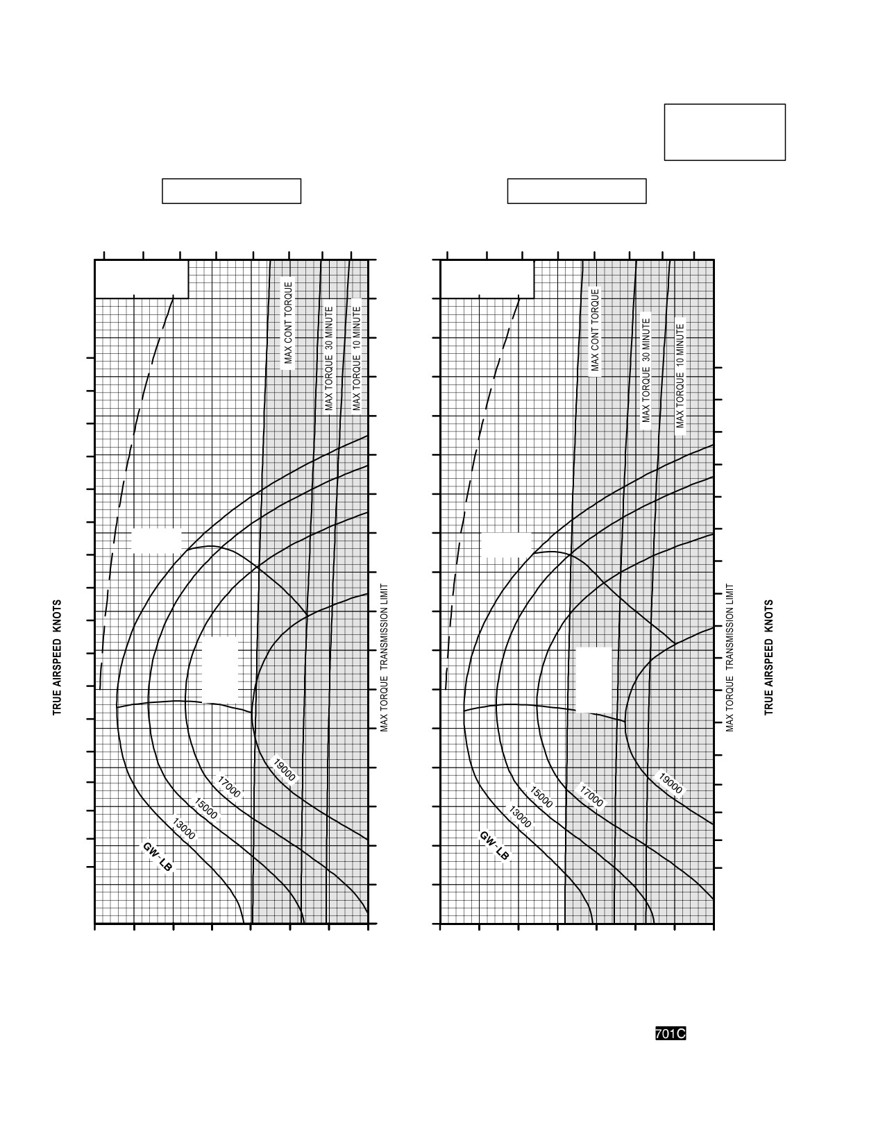
TM 1-1520-251-10
CRUISE
CRUISE
AH64D
PRESSURE ALTITUDE 10,000 FEET
T700GE701C
101% NR RPM, 8 HELLFIRE CONFIGURATION, JP8 FUEL
FAT = 50° C
FAT = 40° C
INDICATED
TOTAL FUEL FLOW LB/HOUR
TOTAL FUEL FLOW LB/HOUR
AIRSPEED
600
800
1000
1200
KNOTS
600
800
1000
1200
170
∆ Q %
∆ Q %
∆ F = 10.0 SQ FT
∆ F = 10.0 SQ FT
180
0
10
20
0
10
20
160
180
170
150
170
160
160
140
150
V
NE
150
130
140
V
NE
140
120
130
130
110
120
MAX
120
RANGE
MAX
100
RANGE
110
110
90
100
100
80
90
MAX
90
R/C
OR
80
70
MAX
80
END
70
60
70
MAX
R/C
60
50
OR
60
MAX
END
50
40
50
40
40
30
30
30
20
20
20
10
0
30
40
50
60
70
80
90
100
30
40
50
60
70
80
90
100
INDICATED TORQUE PER ENGINE %
INDICATED TORQUE PER ENGINE %
DATA BASIS: DERIVED FROM FLIGHT TEST AND ENGINE MODEL SPEC NO. E1290, 15 APRIL 1988
LBA0224
Figure 7A-24. Cruise Chart, 10,000 Feet, - 50°C and - 40°C (sheet 1 of 5)
Use or disclosure of this information is subject to the restriction(s) on the title page of this document.
7A-53
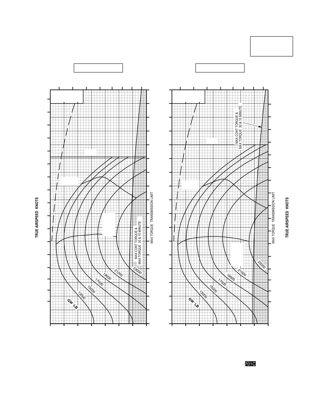
TM 1-1520-251-10
CRUISE
CRUISE
PRESSURE ALTITUDE 10,000 FEET
AH64D
T700GE701C
101% NR RPM, 8 HELLFIRE CONFIGURATION, JP8 FUEL
FAT = 30 °C
FAT = 20 °C
INDICATED
TOTAL FUEL FLOW LB/HOUR
AIRSPEED
TOTAL FUEL FLOW LB/HOUR
600
800
1000
1200
KNOTS
600
800
1000
1200
170
∆ Q %
∆ Q %
∆ F = 10.0 SQ FT
∆ F = 10.0 SQ FT
0
10
20
0
10
20
160
180
180
150
170
170
140
160
160
150
130
150
140
120
140
130
110
130
120
MAX
MAX
RANGE
100
120
RANGE
110
90
110
100
100
80
90
MAX
90
R/C
70
OR
80
MAX
MAX
80
R/C
END
OR
60
70
MAX
70
END
50
60
60
50
40
50
40
40
30
30
30
20
20
20
10
0
30
40
50
60
70
80
90
100
30
40
50
60
70
80
90
100
INDICATED TORQUE PER ENGINE %
INDICATED TORQUE PER ENGINE %
DATA BASIS: DERIVED FROM FLIGHT TEST AND ENGINE MODEL SPEC NO. E1290, 15 APRIL 1988
LBA0225
Figure 7A-24. Cruise Chart, 10,000 Feet, - 30°C and - 20°C (sheet 2 of 5)
Use or disclosure of this information is subject to the restriction(s) on the title page of this document.
7A-54
Change 3
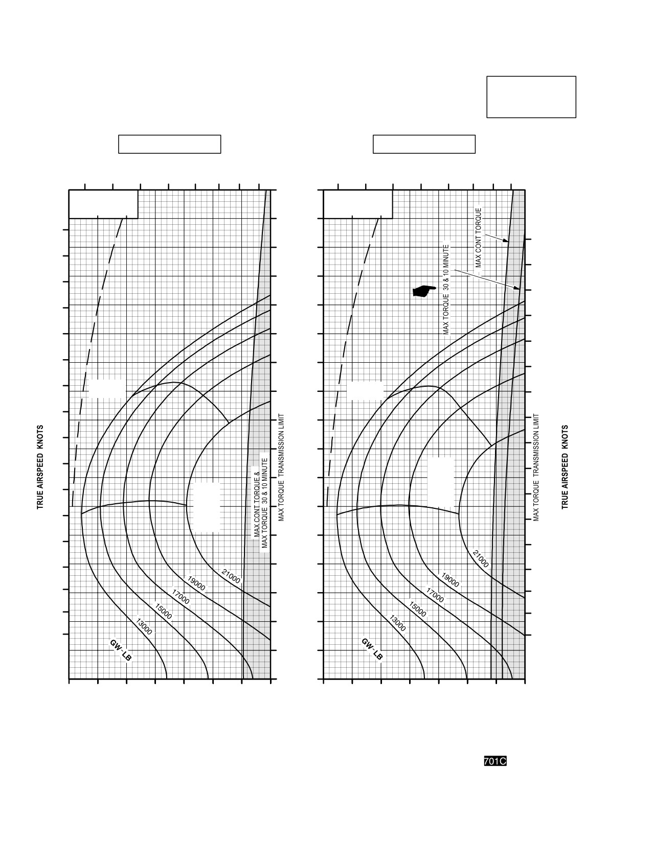
TM 1-1520-251-10
CRUISE
CRUISE
AH64D
PRESSURE ALTITUDE 10,000 FEET
T700GE701C
101% NR RPM, 8 HELLFIRE CONFIGURATION, JP8 FUEL
FAT = 10 °C
FAT = 0 °C
TOTAL FUEL FLOW LB/HOUR
INDICATED
TOTAL FUEL FLOW LB/HOUR
AIRSPEED
600
800
1000
1200
600
800
1000
1200
KNOTS
170
∆ Q %
∆ Q %
∆ F = 10.0 SQ FT
∆ F = 10.0 SQ FT
0
10
20
0
10
20
160
180
150
180
170
140
170
160
130
160
150
150
120
140
140
110
130
130
MAX
MAX
100
RANGE
120
RANGE
120
90
110
110
90
100
80
100
90
MAX
MAX
70
R/C
R/C
OR
OR
80
MAX
MAX
80
60
END
END
70
70
50
60
60
40
50
50
40
30
40
30
30
20
20
20
10
0
30
40
50
60
70
80
90
100
30
40
50
60
70
80
90
100
INDICATED TORQUE PER ENGINE %
INDICATED TORQUE PER ENGINE %
DATA BASIS: DERIVED FROM FLIGHT TEST AND ENGINE MODEL SPEC NO. E1290, 15 APRIL 1988
LBA0226
Figure 7A-24. Cruise Chart, 10,000 Feet, - 10°C and 0°C (sheet 3 of 5)
Use or disclosure of this information is subject to the restriction(s) on the title page of this document.
7A-55
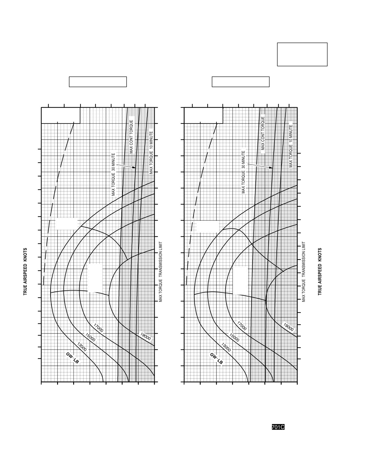
TM 1-1520-251-10
CRUISE
CRUISE
AH64D
PRESSURE ALTITUDE 10,000 FEET
T700GE701C
101% NR RPM, 8 HELLFIRE CONFIGURATION, JP8 FUEL
FAT = +10 °C
FAT = +20 °C
INDICATED
TOTAL FUEL FLOW LB/HOUR
TOTAL FUEL FLOW LB/HOUR
AIRSPEED
600
800
1000
1200
KNOTS
600
800
1000
1200
170
∆ Q %
∆ Q %
∆ F = 10.0 SQ FT
∆ F = 10.0 SQ FT
0
10
20
0
10
20
160
150
180
180
140
170
170
130
160
160
150
120
150
140
110
140
130
100
130
MAX
MAX
RANGE
120
RANGE
120
90
110
900
80
100
100
MAX
70
90
MAX
R/C
90
R/C
OR
OR
80
MAX
60
MAX
80
END
END
70
70
50
60
60
40
50
50
40
30
40
30
30
20
20
20
10
0
30
40
50
60
70
80
90
100
30
40
50
60
70
80
90
100
INDICATED TORQUE PER ENGINE %
INDICATED TORQUE PER ENGINE %
DATA BASIS: DERIVED FROM FLIGHT TEST AND ENGINE MODEL SPEC NO. E1290, 15 APRIL 1988
LBA0227
Figure 7A-24. Cruise Chart, 10,000 Feet, +10°C and +20°C (sheet 4 of 5)
Use or disclosure of this information is subject to the restriction(s) on the title page of this document.
7A-56
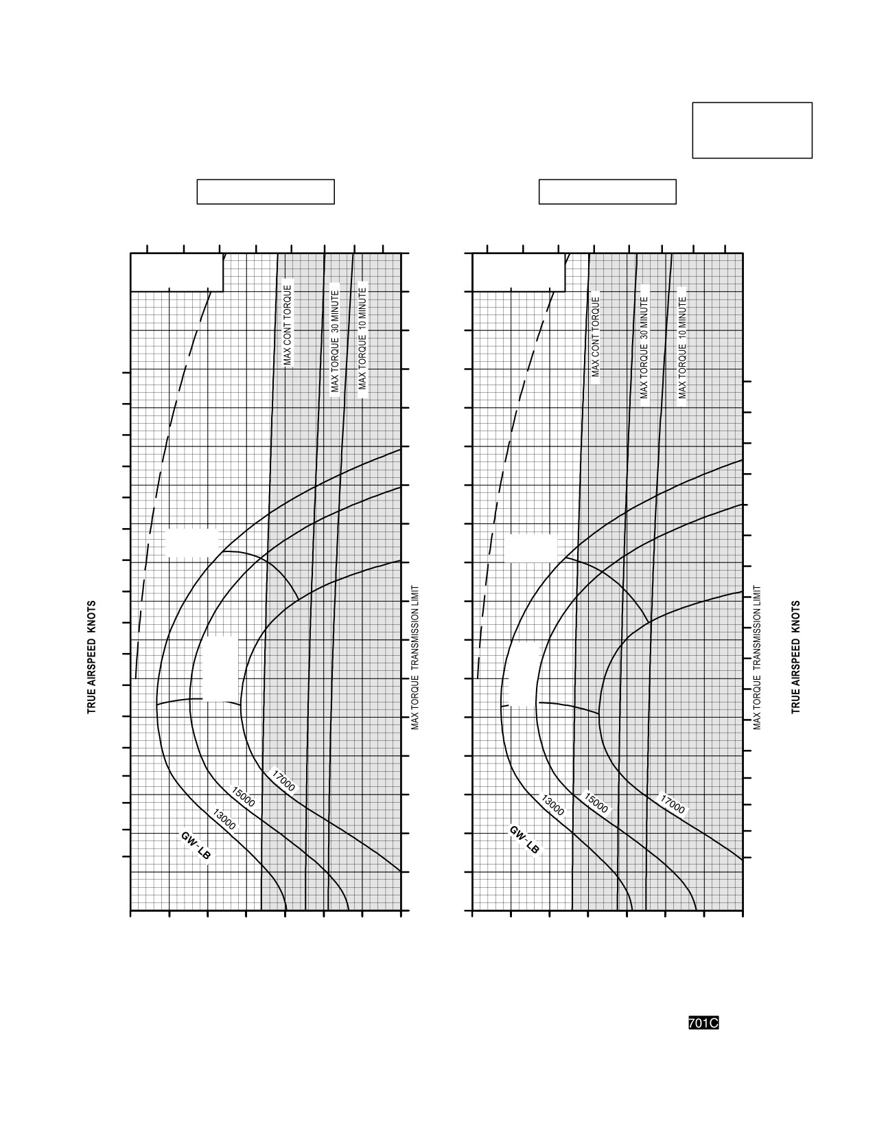
TM 1-1520-251-10
CRUISE
CRUISE
AH64D
PRESSURE ALTITUDE 10,000 FEET
T700GE701C
101% NR RPM, 8 HELLFIRE CONFIGURATION, JP8 FUEL
FAT = +30 °C
FAT = +40 °C
INDICATED
TOTAL FUEL FLOW LB/HOUR
AIRSPEED
TOTAL FUEL FLOW LB/HOUR
KNOTS
600
800
1000
1200
600
800
1000
1200
170
∆ Q %
∆ Q %
∆ F = 10.0 SQ FT
∆ F = 10.0 SQ FT
0
10
20
0
10
20
160
150
180
140
180
170
130
170
160
120
160
150
150
110
140
140
100
130
MAX
130
MAX
RANGE
RANGE
120
90
120
90
110
110
80
100
100
70
MAX
90
MAX
R/C
90
R/C
OR
60
OR
80
MAX
80
MAX
END
END
70
50
70
60
60
40
50
50
30
40
40
30
30
20
20
20
10
0
30
40
50
60
70
80
90
100
30
40
50
60
70
80
90
100
INDICATED TORQUE PER ENGINE %
INDICATED TORQUE PER ENGINE %
DATA BASIS: DERIVED FROM FLIGHT TEST AND ENGINE MODEL SPEC NO. E1290, 15 APRIL 1988
LBA0228
Figure 7A-24. Cruise Chart, 10,000 Feet, +30°C and +40°C (sheet 5 of 5)
Use or disclosure of this information is subject to the restriction(s) on the title page of this document.
7A-57
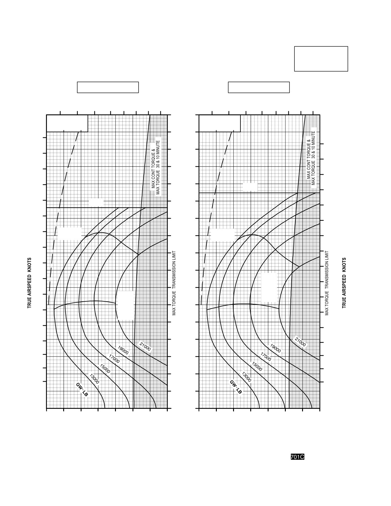
TM 1-1520-251-10
CRUISE
CRUISE
PRESSURE ALTITUDE 12,000 FEET
AH64D
T700GE701C
101% NR RPM, 8 HELLFIRE CONFIGURATION, JP8 FUEL
FAT = 50°C
FAT = 40°C
INDICATED
AIRSPEED
TOTAL FUEL FLOW LB/HOUR
TOTAL FUEL FLOW LB/HOUR
KNOTS
600
800
1000
1200
600
800
1000
1200
170
∆ Q %
∆ Q %
∆ F = 10.0 SQ FT
∆ F = 10.0 SQ FT
0
10
20
0
10
20
160
180
180
150
170
170
140
160
160
150
130
V
NE
150
140
120
V NE
140
130
110
130
120
MAX
MAX
RANGE
100
120
RANGE
110
110
90
90
100
100
80
90
MAX
90
R/C
70
OR
80
MAX
MAX
80
R/C
END
OR
60
70
MAX
70
END
50
60
60
50
40
50
40
40
30
30
30
20
20
20
10
0
30
40
50
60
70
80
90
100
30
40
50
60
70
80
90
100
INDICATED TORQUE PER ENGINE %
INDICATED TORQUE PER ENGINE %
DATA BASIS: DERIVED FROM FLIGHT TEST AND ENGINE MODEL SPEC NO. E1290, 15 APRIL 1988
LBA0229
Figure 7A-25. Cruise Chart, 12,000 Feet, - 50°C and - 40°C (sheet 1 of 5)
Use or disclosure of this information is subject to the restriction(s) on the title page of this document.
7A-58
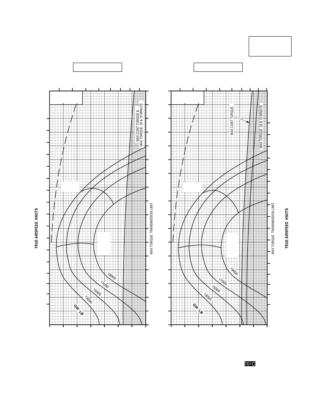
TM 1-1520-251-10
CRUISE
CRUISE
AH64D
PRESSURE ALTITUDE 12,000 FEET
T700GE701C
101% NR RPM, 8 HELLFIRE CONFIGURATION, JP8 FUEL
FAT = 30°C
FAT = 20°C
INDICATED
TOTAL FUEL FLOW LB/HOUR
AIRSPEED
TOTAL FUEL FLOW LB/HOUR
KNOTS
600
800
1000
1200
600
800
1000
1200
1400
170
∆ Q %
∆ Q %
∆ F = 10.0 SQ FT
∆ F = 10.0 SQ FT
0
10
20
0
10
20
160
180
150
180
170
140
170
160
130
160
150
150
120
140
140
110
130
130
MAX
MAX
100
120
RANGE
RANGE
120
110
90
110
90
100
80
100
90
70
90
MAX
80
MAX
R/C
80
60
R/C
OR
OR
70
MAX
MAX
70
END
50
END
60
60
40
50
50
40
30
40
30
30
20
20
20
10
0
30
40
50
60
70
80
90
100
30
40
50
60
70
80
90
100
INDICATED TORQUE PER ENGINE %
INDICATED TORQUE PER ENGINE %
DATA BASIS: DERIVED FROM FLIGHT TEST AND ENGINE MODEL SPEC NO. E1290, 15 APRIL 1988
LBA0230
Figure 7A-25. Cruise Chart, 12,000 Feet, - 30°C and - 20°C (sheet 2 of 5)
Use or disclosure of this information is subject to the restriction(s) on the title page of this document.
7A-59
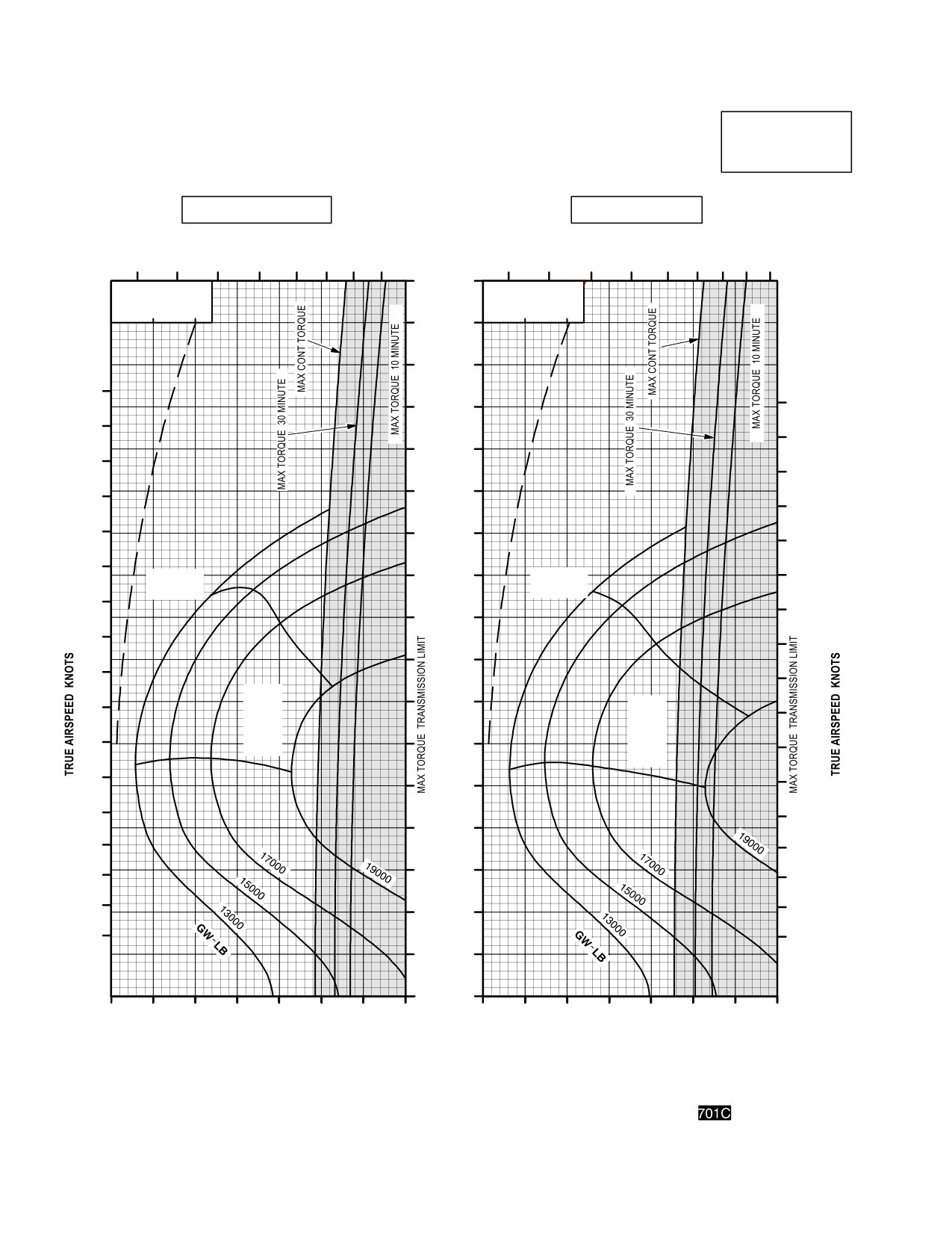
TM 1-1520-251-10
CRUISE
CRUISE
AH64D
PRESSURE ALTITUDE 12,000 FEET
T700GE701C
101% NR RPM, 8 HELLFIRE CONFIGURATION, JP8 FUEL
FAT = 10°C
FAT = 0°C
INDICATED
AIRSPEED
TOTAL FUEL FLOW LB/HOUR
TOTAL FUEL FLOW LB/HOUR
KNOTS
600
800
1000
1200
600
800
1000
1200
1400
170
∆ Q %
∆ Q %
∆ F = 10.0 SQ FT
∆ F = 10.0 SQ FT
0
10
20
0
10
20
160
150
180
180
140
170
170
130
160
160
120
150
150
140
110
140
130
MAX
100
MAX
130
RANGE
RANGE
120
120
90
110
900
80
100
100
MAX
90
70
MAX
R/C
90
R/C
OR
MAX
OR
80
60
MAX
80
END
END
70
70
50
60
60
40
50
50
30
40
40
30
30
20
20
20
10
0
30
40
50
60
70
80
90
100
30
40
50
60
70
80
90
100
INDICATED TORQUE PER ENGINE %
INDICATED TORQUE PER ENGINE %
DATA BASIS: DERIVED FROM FLIGHT TEST AND ENGINE MODEL SPEC NO. E1290, 15 APRIL 1988
LBA0232
Figure 7A-25. Cruise Chart, 12,000 Feet, - 10°C and 0°C (sheet 3 of 5)
Use or disclosure of this information is subject to the restriction(s) on the title page of this document.
7A-60
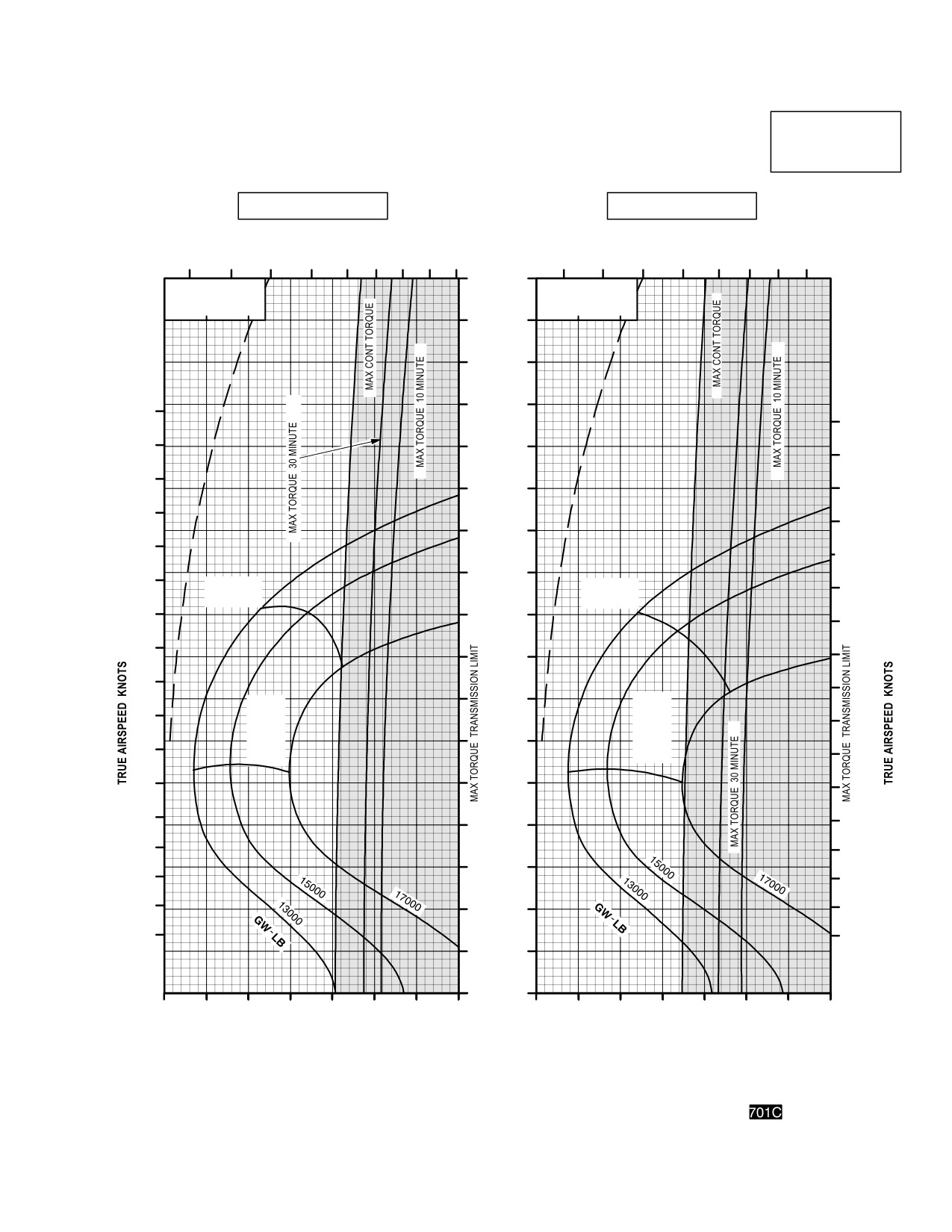
TM 1-1520-251-10
CRUISE
CRUISE
AH64D
PRESSURE ALTITUDE 12,000 FEET
T700GE701C
101% NR RPM, 8 HELLFIRE CONFIGURATION, JP8 FUEL
FAT = +10°C
FAT = +20°C
INDICATED
AIRSPEED
TOTAL FUEL FLOW LB/HOUR
KNOTS
TOTAL FUEL FLOW LB/HOUR
600
800
1000
1200
1400
600
800
1000
1200
170
∆ Q %
∆ Q %
∆ F = 10.0 SQ FT
∆ F = 10.0 SQ FT
0
10
20
0
10
20
160
150
140
180
180
170
130
170
160
120
160
150
150
110
140
140
100
130
MAX
MAX
130
RANGE
RANGE
120
90
120
90
110
80
110
100
100
70
MAX
MAX
90
R/C
R/C
90
OR
OR
60
MAX
80
MAX
80
END
END
70
50
70
60
60
40
50
50
30
40
40
30
30
20
20
20
10
0
30
40
50
60
70
80
90
100
30
40
50
60
70
80
90
100
INDICATED TORQUE PER ENGINE %
INDICATED TORQUE PER ENGINE %
DATA BASIS: DERIVED FROM FLIGHT TEST AND ENGINE MODEL SPEC NO. E1290, 15 APRIL 1988
LBA0232
Figure 7A-25. Cruise Chart, 12,000 Feet, +10°C and +20°C (sheet 4 of 5)
Use or disclosure of this information is subject to the restriction(s) on the title page of this document.
7A-61
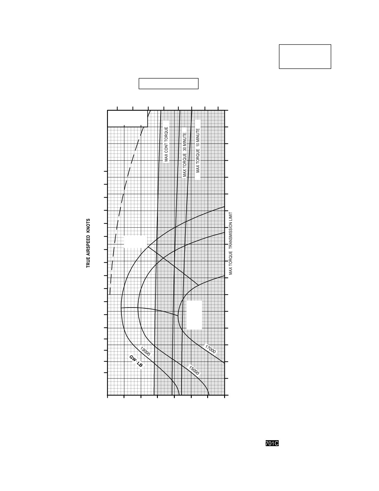
TM 1-1520-251-10
CRUISE
CRUISE
AH64D
PRESSURE ALTITUDE 12,000 FEET
T700GE701C
101% NR RPM, 8 HELLFIRE CONFIGURATION, JP8 FUEL
FAT = +30°C
INDICATED
TOTAL FUEL FLOW LB/HOUR
AIRSPEED
600
800
1000
1200
KNOTS
170
∆ Q %
∆ F = 10.0 SQ FT
0
10
20
160
150
140
180
130
170
120
160
150
110
140
100
130
MAX
RANGE
90
120
110
80
100
70
90
60
80
MAX
R/C
50
70
OR
MAX
60
END
40
50
30
40
30
20
20
10
0
30
40
50
60
70
80
90
100
INDICATED TORQUE PER ENGINE %
DATA BASIS: DERIVED FROM FLIGHT TEST AND ENGINE MODEL SPEC NO. E1290, 15 APRIL 1988
LBA0233
Figure 7A-25. Cruise Chart, 12,000 Feet, +30°C (sheet 5 of 5)
Use or disclosure of this information is subject to the restriction(s) on the title page of this document.
7A-62
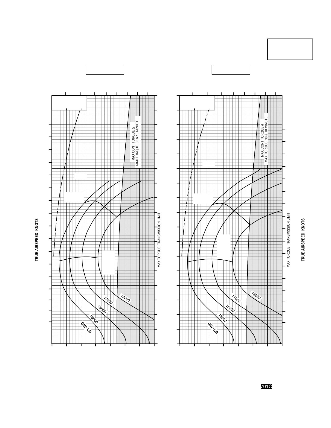
TM 1-1520-251-10
CRUISE
CRUISE
AH64D
PRESSURE ALTITUDE 14,000 FEET
T700GE701C
101% NR RPM, 8 HELLFIRE CONFIGURATION, JP8 FUEL
FAT = 50°C
FAT = 40°C
INDICATED
TOTAL FUEL FLOW LB/HOUR
TOTAL FUEL FLOW LB/HOUR
AIRSPEED
KNOTS
600
800
1000
1200
600
800
1000
1200
170
∆ Q %
∆ Q %
∆ F = 10.0 SQ FT
∆ F = 10.0 SQ FT
0
10
20
0
10
20
160
180
150
180
170
140
170
160
130
160
150
V
NE
150
120
140
V
NE
140
110
130
130
MAX
100
MAX
120
RANGE
RANGE
120
110
90
110
90
100
80
100
90
MAX
90
70
R/C
OR
80
MAX
MAX
80
R/C
60
END
70
OR
70
MAX
END
50
60
60
40
50
50
40
30
40
30
30
20
20
20
10
0
30
40
50
60
70
80
90
100
30
40
50
60
70
80
90
100
INDICATED TORQUE PER ENGINE %
INDICATED TORQUE PER ENGINE %
DATA BASIS: DERIVED FROM FLIGHT TEST AND ENGINE MODEL SPEC NO. E1290, 15 APRIL 1988
LBA0234
Figure 7A-26. Cruise Chart, 14,000 Feet, - 50°C and - 40°C (sheet 1 of 5)
Use or disclosure of this information is subject to the restriction(s) on the title page of this document.
7A-63
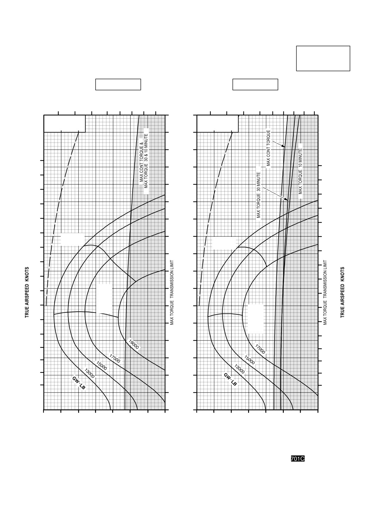
TM 1-1520-251-10
CRUISE
CRUISE
AH64D
PRESSURE ALTITUDE 14,000 FEET
T700GE701C
101% NR RPM, 8 HELLFIRE CONFIGURATION, JP8 FUEL
FAT = 30°C
FAT = 20°C
INDICATED
TOTAL FUEL FLOW LB/HOUR
AIRSPEED
TOTAL FUEL FLOW LB/HOUR
KNOTS
600
800
1000
1200
600
800
1000
1200
1400
170
∆ Q %
∆ Q %
∆ F = 10.0 SQ FT
∆ F = 10.0 SQ FT
0
10
20
0
10
20
160
150
180
180
140
170
170
130
160
160
120
150
150
140
110
140
130
MAX
100
130
MAX
RANGE
120
RANGE
120
90
110
90
80
100
100
MAX
70
90
90
R/C
OR
80
MAX
60
MAX
80
END
R/C
70
OR
70
50
MAX
END
60
60
40
50
50
30
40
40
30
30
20
20
20
10
0
30
40
50
60
70
80
90
100
30
40
50
60
70
80
90
100
INDICATED TORQUE PER ENGINE %
INDICATED TORQUE PER ENGINE %
DATA BASIS: DERIVED FROM FLIGHT TEST AND ENGINE MODEL SPEC NO. E1290, 15 APRIL 1988
LBA0235
Figure 7A-26. Cruise Chart, 14,000 Feet, - 30°C and - 20°C (sheet 2 of 5)
Use or disclosure of this information is subject to the restriction(s) on the title page of this document.
7A-64
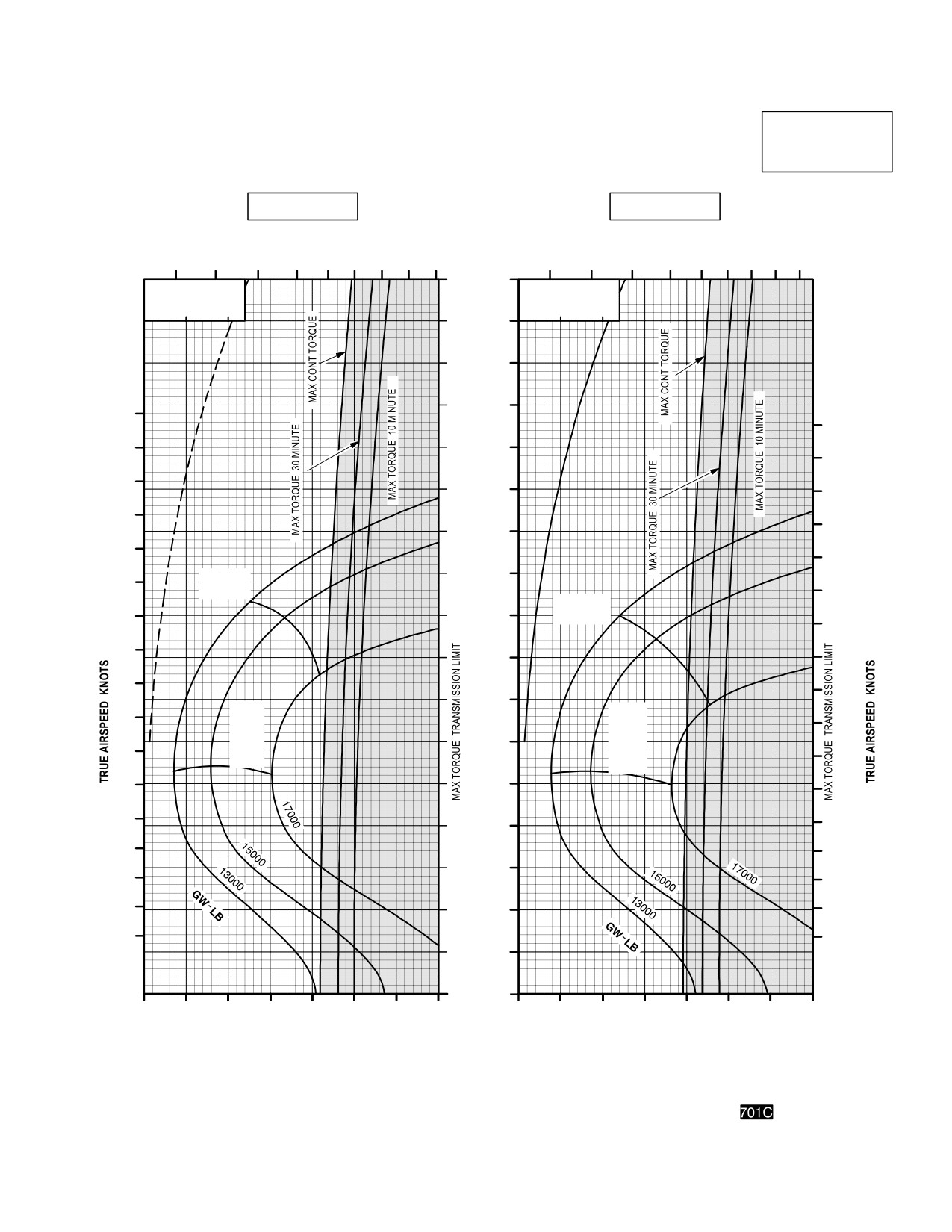
TM 1-1520-251-10
CRUISE
CRUISE
AH64D
PRESSURE ALTITUDE 14,000 FEET
T700GE701C
101% NR RPM, 8 HELLFIRE CONFIGURATION, JP8 FUEL
FAT = 10°C
FAT = 0°C
INDICATED
TOTAL FUEL FLOW LB/HOUR
TOTAL FUEL FLOW LB/HOUR
AIRSPEED
KNOTS
600
800
1000
1200
1400
600
800
1000
1200
1400
170
∆ Q %
∆ Q %
∆ F = 10.0 SQ FT
∆ F = 10.0 SQ FT
0
10
20
0
10
20
160
150
140
180
180
170
130
170
160
120
160
150
150
110
140
140
100
130
MAX
RANGE
130
MAX
120
90
RANGE
120
90
110
80
110
100
100
70
MAX
MAX
90
R/C
90
R/C
OR
60
OR
80
MAX
MAX
80
END
END
70
50
70
60
60
40
50
50
30
40
40
30
30
20
20
20
10
0
30
40
50
60
70
80
90
100
30
40
50
60
70
80
90
100
INDICATED TORQUE PER ENGINE %
INDICATED TORQUE PER ENGINE %
DATA BASIS: DERIVED FROM FLIGHT TEST AND ENGINE MODEL SPEC NO. E1290, 15 APRIL 1988
LBA0236
Figure 7A-26. Cruise Chart, 14,000 Feet, - 10°C and 0°C (sheet 3 of 5)
Use or disclosure of this information is subject to the restriction(s) on the title page of this document.
7A-65
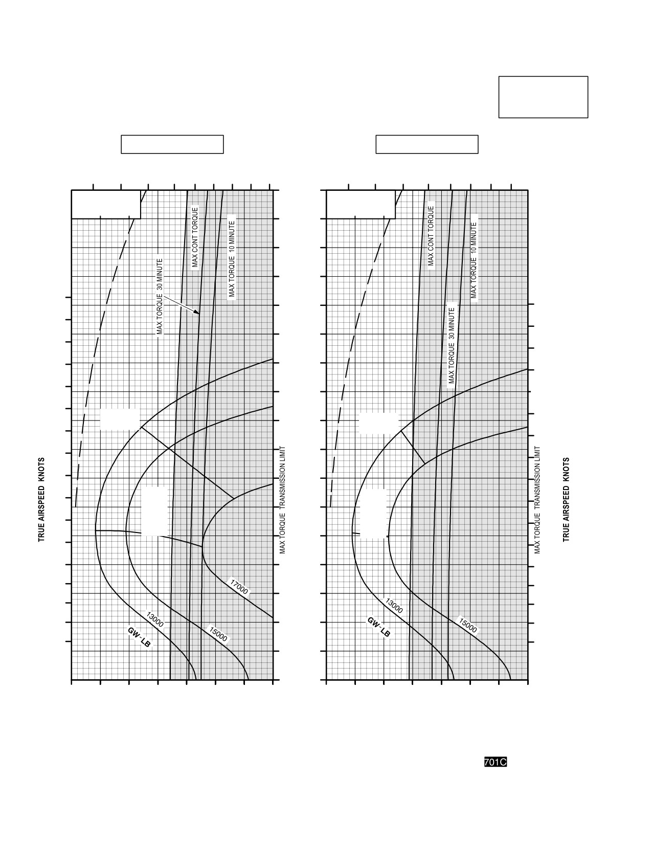
TM 1-1520-251-10
CRUISE
CRUISE
AH64D
PRESSURE ALTITUDE 14,000 FEET
T700GE701C
101% NR RPM, 8 HELLFIRE CONFIGURATION, JP8 FUEL
FAT = +10° C
FAT = +20° C
INDICATED
TOTAL FUEL FLOW LB/HOUR
TOTAL FUEL FLOW LB/HOUR
AIRSPEED
600
800
1000
1200
1400
KNOTS
600
800
1000
1200
170
∆ Q %
∆ Q %
∆ F = 10.0 SQ FT
∆ F = 10.0 SQ FT
0
10
20
0
10
20
160
150
140
180
130
180
170
170
120
160
160
150
110
150
140
100
140
130
MAX
130
90
MAX
RANGE
120
RANGE
120
90
80
110
110
100
70
100
90
MAX
MAX
90
R/C
R/C
60
OR
OR
80
MAX
MAX
80
END
END
50
70
70
60
40
60
50
50
30
40
40
30
20
30
20
20
10
0
30
40
50
60
70
80
90
100
30
40
50
60
70
80
90
100
INDICATED TORQUE PER ENGINE %
INDICATED TORQUE PER ENGINE %
DATA BASIS: DERIVED FROM FLIGHT TEST AND ENGINE MODEL SPEC NO. E1290, 15 APRIL 1988
LBA0237
Figure 7A-26. Cruise Chart, 14,000 Feet, +10°C and +20°C (sheet 4 of 5)
Use or disclosure of this information is subject to the restriction(s) on the title page of this document.
7A-66
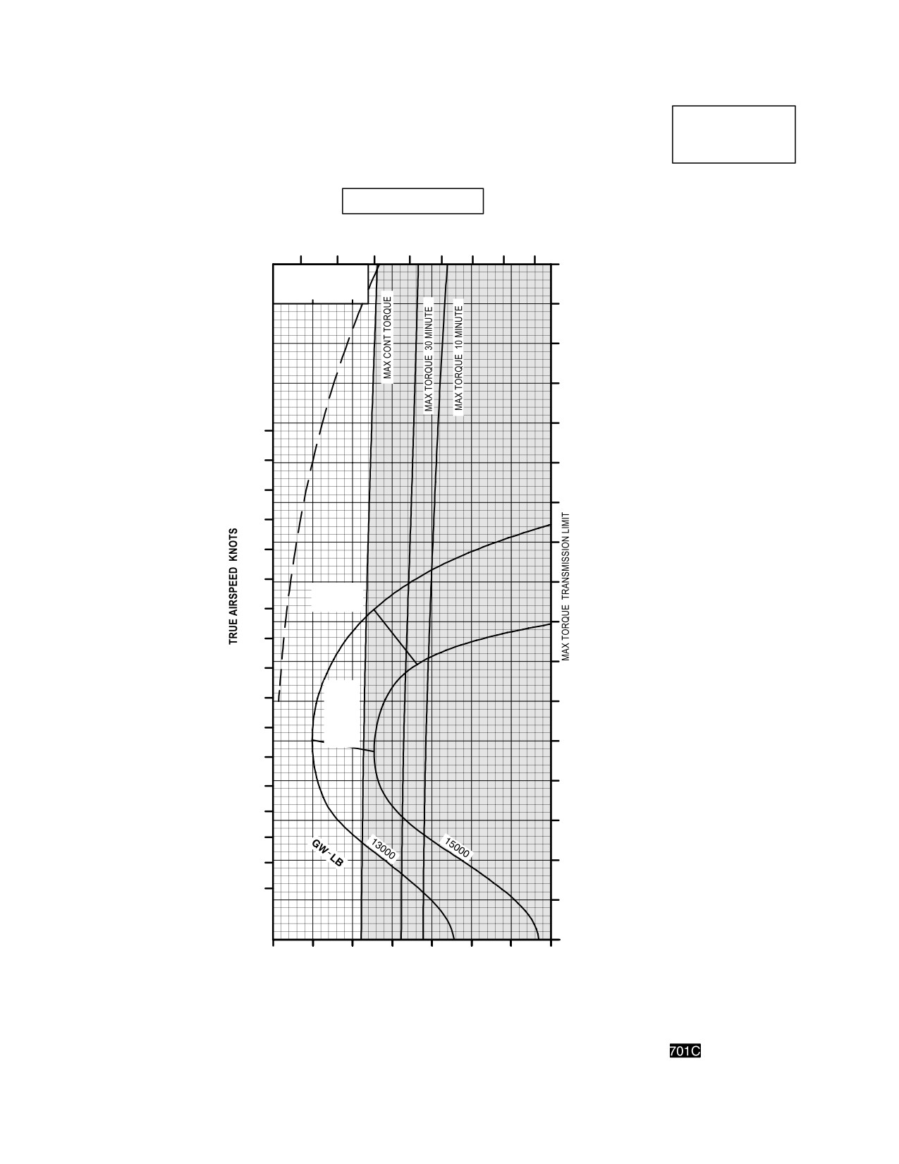
TM 1-1520-251-10
CRUISE
CRUISE
AH64D
PRESSURE ALTITUDE 14,000 FEET
T700GE701C
101% NR RPM, 8 HELLFIRE CONFIGURATION, JP8 FUEL
FAT =+30° C
INDICATED
TOTAL FUEL FLOW LB/HOUR
AIRSPEED
600
800
1000
1200
KNOTS
170
∆ Q %
∆ F = 10.0 SQ FT
0
10
20
160
150
140
130
180
170
120
160
110
150
100
140
130
90
MAX
120
RANGE
80
110
70
100
MAX
90
R/C
60
OR
80
MAX
END
50
70
60
40
50
30
40
30
20
20
10
0
30
40
50
60
70
80
90
100
INDICATED TORQUE PER ENGINE %
DATA BASIS: DERIVED FROM FLIGHT TEST AND ENGINE MODEL SPEC NO. E1290, 15 APRIL 1988
LBA0238
Figure 7A-26. Cruise Chart, 14,000 Feet, +30°C (sheet 5 of 5)
Use or disclosure of this information is subject to the restriction(s) on the title page of this document.
7A-67
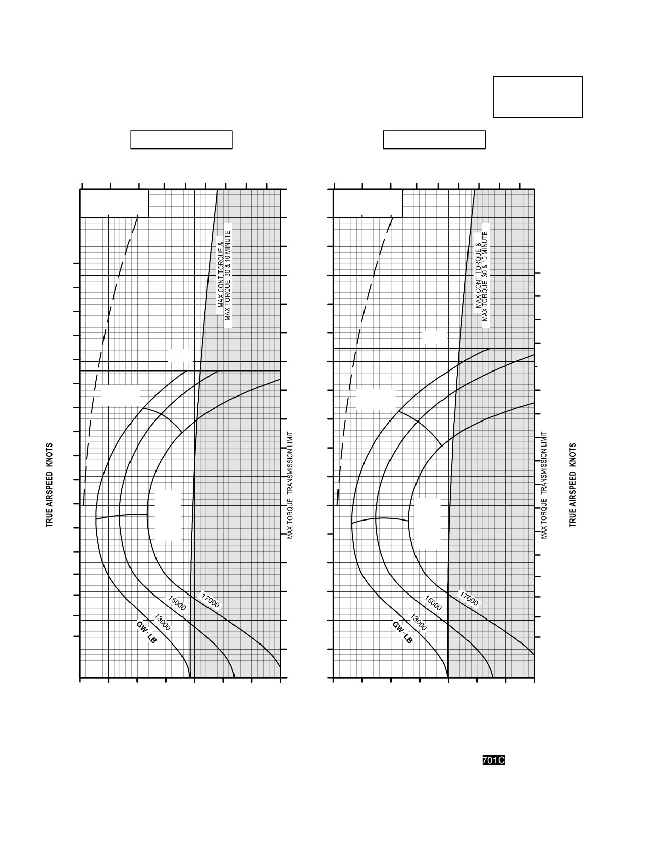
TM 1-1520-251-10
CRUISE
CRUISE
AH64D
PRESSURE ALTITUDE 16,000 FEET
T700GE701C
101% NR RPM, 8 HELLFIRE CONFIGURATION, JP8 FUEL
FAT = 50°C
FAT = 40°C
INDICATED
AIRSPEED
TOTAL FUEL FLOW LB/HOUR
TOTAL FUEL FLOW LB/HOUR
KNOTS
500
700
900
1100
1300
500
700
900
1100
1300
170
∆ Q %
∆ Q %
∆ F = 10.0 SQ FT
∆ F = 10.0 SQ FT
0
10
20
0
10
20
160
150
180
180
140
170
170
130
160
160
150
120
V
NE
150
V
140
NE
110
140
130
MAX
100
130
MAX
RANGE
RANGE
120
120
90
110
900
80
100
100
90
70
90
MAX
80
MAX
R/C
60
80
OR
R/C
70
MAX
OR
70
END
50
MAX
END
60
60
40
50
50
40
30
40
30
30
20
20
20
10
0
30
40
50
60
70
80
90
100
30
40
50
60
70
80
90
100
INDICATED TORQUE PER ENGINE %
INDICATED TORQUE PER ENGINE %
DATA BASIS: DERIVED FROM FLIGHT TEST AND ENGINE MODEL SPEC NO. E1290, 15 APRIL 1988
LBA0239
Figure 7A-27. Cruise chart, 16,000 Feet, - 50°C and - 40°C (sheet 1 of 4)
Use or disclosure of this information is subject to the restriction(s) on the title page of this document.
7A-68
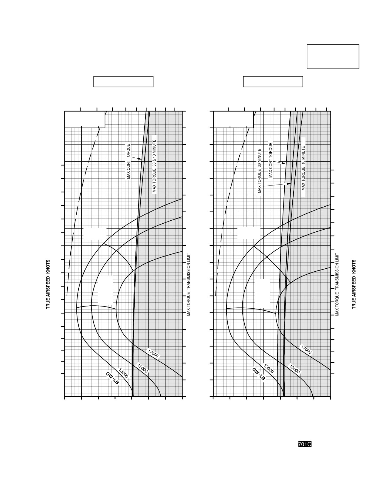
TM 1-1520-251-10
CRUISE
CRUISE
AH64D
PRESSURE ALTITUDE 16,000 FEET
T700GE701C
101% NR RPM, 8 HELLFIRE CONFIGURATION, JP8 FUEL
FAT = 30°C
FAT = 20°C
INDICATED
AIRSPEED
TOTAL FUEL FLOW LB/HOUR
KNOTS
TOTAL FUEL FLOW LB/HOUR
600
800
1000
1200
1400
600
800
1000
1200
1400
170
∆ Q %
∆ Q %
∆ F = 10.0 SQ FT
∆ F = 10.0 SQ FT
0
10
20
0
10
20
160
150
140
180
180
170
130
170
160
120
160
150
150
110
140
140
100
MAX
130
MAX
RANGE
RANGE
130
120
90
120
90
110
80
110
100
100
MAX
70
MAX
90
R/C
R/C
90
OR
OR
MAX
60
80
MAX
END
80
END
70
50
70
60
60
40
50
50
30
40
40
30
30
20
20
20
10
0
30
40
50
60
70
80
90
100
30
40
50
60
70
80
90
100
INDICATED TORQUE PER ENGINE %
INDICATED TORQUE PER ENGINE %
DATA BASIS: DERIVED FROM FLIGHT TEST AND ENGINE MODEL SPEC NO. E1290, 15 APRIL 1988
LBA0240
Figure 7A-27. Cruise chart, 16,000 Feet, - 30°C and - 20°C (sheet 2 of 4)
Use or disclosure of this information is subject to the restriction(s) on the title page of this document.
7A-69
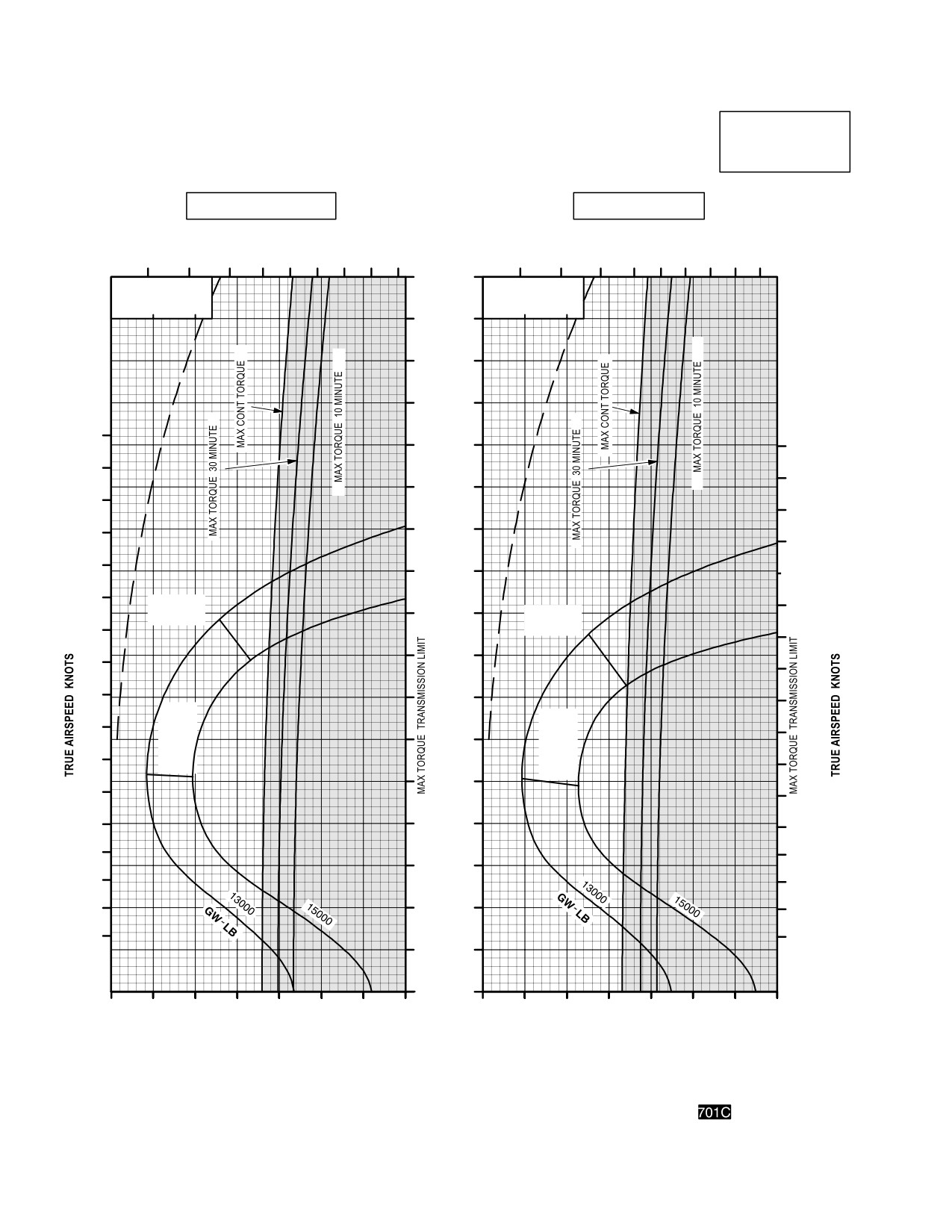
TM 1-1520-251-10
CRUISE
CRUISE
AH64D
PRESSURE ALTITUDE 16,000 FEET
T700GE701C
101% NR RPM, 8 HELLFIRE CONFIGURATION, JP8 FUEL
FAT = 10°C
FAT = 0°C
INDICATED
AIRSPEED
TOTAL FUEL FLOW LB/HOUR
TOTAL FUEL FLOW LB/HOUR
KNOTS
600
800
1000
1200
1400
600
800
1000
1200
1400
170
∆ Q %
∆ Q %
∆ F = 10.0 SQ FT
∆ F = 10.0 SQ FT
0
10
20
0
10
20
160
150
140
180
130
180
170
170
120
160
160
150
110
150
140
100
140
130
MAX
130
90
MAX
RANGE
120
RANGE
120
90
80
110
110
100
70
100
MAX
MAX
90
R/C
R/C
90
OR
60
OR
MAX
80
MAX
80
END
END
50
70
70
60
40
60
50
50
30
40
40
30
20
30
20
20
10
0
30
40
50
60
70
80
90
100
30
40
50
60
70
80
90
100
INDICATED TORQUE PER ENGINE %
INDICATED TORQUE PER ENGINE %
DATA BASIS: DERIVED FROM FLIGHT TEST AND ENGINE MODEL SPEC NO. E1290, 15 APRIL 1988
LBA0241
Figure 7A-27. Cruise Chart, 16,000 Feet, - 10°C and 0°C (sheet 3 of 4)
Use or disclosure of this information is subject to the restriction(s) on the title page of this document.
7A-70
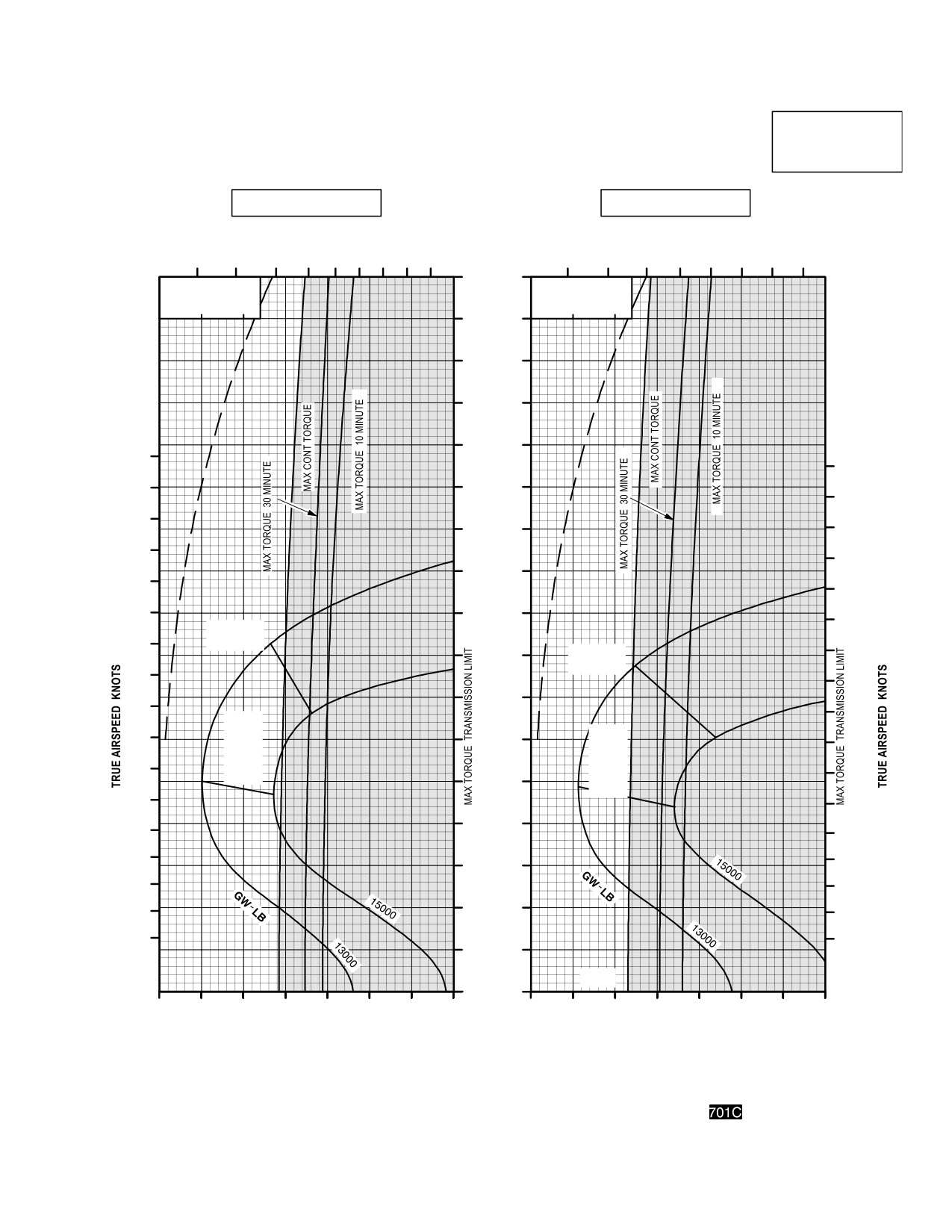
TM 1-1520-251-10
CRUISE
CRUISE
AH64D
PRESSURE ALTITUDE 16,000 FEET
T700GE701C
101% NR RPM, 8 HELLFIRE CONFIGURATION, JP8 FUEL
FAT = +10°C
FAT = +20°C
INDICATED
AIRSPEED
TOTAL FUEL FLOW LB/HOUR
TOTAL FUEL FLOW LB/HOUR
KNOTS
600
800
1000
1200
1400
600
800
1000
1200
170
∆ Q %
∆ Q %
∆ F = 10.0 SQ FT
∆ F = 10.0 SQ FT
0
10
20
0
10
20
160
150
140
130
180
180
170
120
170
160
110
160
150
150
100
140
140
130
90
130
MAX
120
RANGE
90
80
MAX
120
RANGE
110
110
70
100
100
MAX
90
R/C
MAX
60
90
OR
R/C
MAX
OR
80
80
END
MAX
50
END
70
70
40
60
60
50
50
30
40
40
30
20
30
20
20
10
V
NE
0
30
40
50
60
70
80
90
100
30
40
50
60
70
80
90
100
INDICATED TORQUE PER ENGINE %
INDICATED TORQUE PER ENGINE %
DATA BASIS: DERIVED FROM FLIGHT TEST AND ENGINE MODEL SPEC NO. E1290, 15 APRIL 1988
LBA0242
Figure 7A-27. Cruise Chart, 16,000 Feet, +10°C (sheet 4 of 4)
Use or disclosure of this information is subject to the restriction(s) on the title page of this document.
7A-71
TM 1-1520-251-10
Section VI. DRAG
7A.24 DESCRIPTION
7A.25 USE OF CHART
To determine the (nF) and the associated multiplying fac-
tor, it is necessary to know what combination of stores is
installed. Enter the chart at the top, move down to the il-
The drag chart (fig 7A-28) shows the change in frontal
lustration that matches the desired combination, and then
area (nF) for each wing-stores combination that can be
move right and read nF and the multiplying factor. Use the
installed on the helicopter. The baseline configuration (pri-
multiplying factor and data in Section V, Cruise to deter-
mary mission) consists of one pylon and one full Hellfire
mine the resulting change in torque.
launcher on each inboard stores station. The baseline
7A.26 CONDITIONS
configuration includes the Wire Strike Protection System
(WSPS), Aircraft Survivability Equipment (ASE) and Fire
The drag chart is based on the primary mission configura-
Control Radar (FCR) kit.
tion having zero change in frontal area.
Use or disclosure of this information is subject to the restriction(s) on the title page of this document.
7A-72
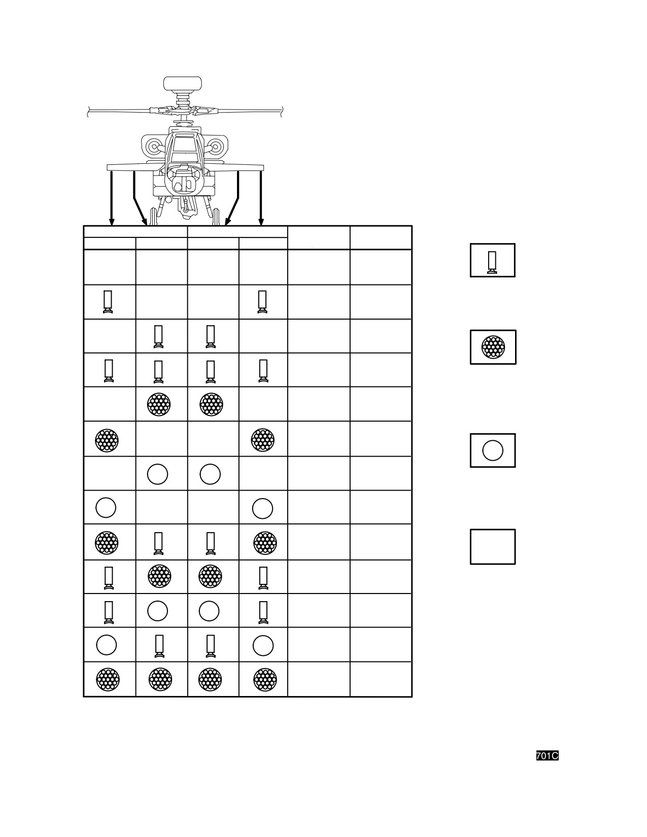
TM 1-1520-251-10
RIGHT WING STORES
LEFT WING STORES
∆ F
MULTIPLYING
OUTBOARD
INBOARD
INBOARD
OUTBOARD
(SQ. FT.)
FACTOR
9.1
0.91
STORES PYLON
(EMPTY)
7.3
0.73
7.3
0.73
5.5
0.55
STORES PYLONS PLUS
19 TUBE ROCKET LAUNCHER
(LOADED WITH 19 ROCKETS)
5.9
0.59
5.9
0.59
3.2
0.32
STORES PYLONS PLUS
EXTERNAL FUEL TANK
3.9
0.39
4.1
0.41
CLEAN STATION
4.1
0.41
1.4
0.14
2.1
0.21
2.7
0.27
n
FOR FCR KIT (MMA, RFI AND DEROTATION UNIT) REMOVAL, ADD+8.1 SQ. FT. TO F AND +0.81
TO MULTIPLYING FACTOR.
LBA0050
Figure 7A-28. Drag Chart and Authorized Armament Configurations (Sheet 1 of 2)
Use or disclosure of this information is subject to the restriction(s) on the title page of this document.
7A-73
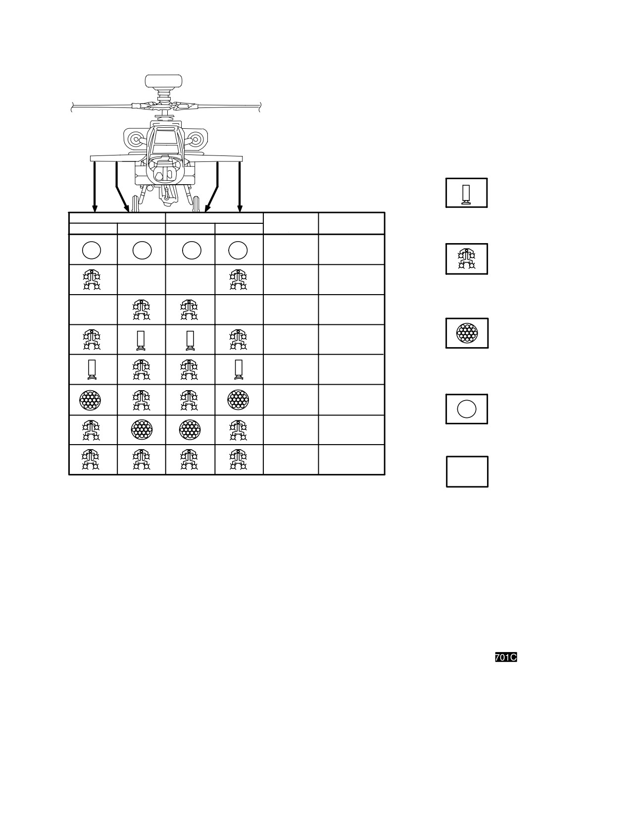
TM 1-1520-251-10
STORES PYLON
RIGHT WING STORES
LEFT WING STORES
∆ F
MULTIPLYING
(EMPTY)
OUTBOARD
INBOARD
INBOARD
OUTBOARD
(SQ. FT.)
FACTOR
+2.0
+0.20
STORES PYLONS PLUS
1.4
0.14
HELLFIRE MISSILE LAUNCHER
(LOADED WITH 4 MISSILES)
0
0
(BASELINE)
(BASELINE)
+0.4
+0.04
STORES PYLONS PLUS
19 TUBE ROCKET LAUNCHER
+1.8
+0.18
(LOADED WITH 19 ROCKETS)
+3.2
+0.32
+1.8
+0.18
STORES PYLONS PLUS
EXTERNAL FUEL TANK
+7.6
+0.76
n
CLEAN STATION
FOR FCR KIT (MMA, RFI AND DEROTATION UNIT) REMOVAL, ADD +8.1 SQ. FT. TO F AND +0.81
TO MULTIPLYING FACTOR.
LBA0051
Figure 7A-28. Drag Chart and Authorized Armament Configurations (Sheet 2 of 2)
Use or disclosure of this information is subject to the restriction(s) on the title page of this document.
7A-74
TM 1-1520-251-10
Section VII. CLIMB - DESCENT
7A.27 DESCRIPTION
gross weight, and then move down and read the torque
change. This torque change must be added to (for climb)
The climb-descent chart (fig 7A-29) shows the change in
or subtracted from (for descent) the torque required for
torque (above and below the torque required for level
level flight (obtained from the appropriate cruise chart) to
flight under the same configuration, gross weight, and at-
obtain a total climb or descent torque.
mospheric conditions) to obtain a desired rate of climb or
descent.
7A.28.2 Alternate Use. By entering the chart with a
known torque change, and moving up to the known gross
7A.28 USE OF CHART
weight and then left, the corresponding rate of climb or de-
scent can also be obtained.
7A.28.1
Primary Use. The primary use of the chart is
illustrated by the example. To determine the change in
7A.29 CONDITIONS
torque, it is necessary to know the gross weight and the
desired rate of climb or descent. Enter the chart at the de-
sired rate of climb or descent, move right to the known
The climb-descent chart is based on 101% rotor RPM.
Use or disclosure of this information is subject to the restriction(s) on the title page of this document.
7A-75
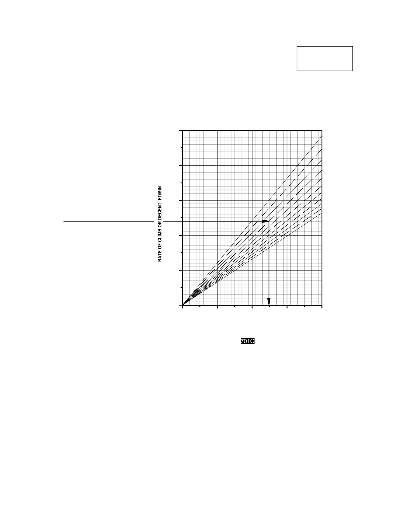
TM 1-1520-251-10
CLIMBDESCENT
CLIMB DESCENT
AH64D
T700GE701C
GROSS WEIGHT LB
5000
12,000
13,000
EXAMPLE
14,000
WANTED
4000
15,000
CALIBRATED TORQUE CHANGE
FOR DESIRED RATE OF CLIMB
16,000
OR DESCENT
17,000
KNOWN OR ESTIMATED
18,000
GROSS WEIGHT = 15,000 LB
3000
19,000
DESIRED R/C = 2400 FT/MIN
20,000
21,000
METHOD
22,000
ENTER R/C HERE
MOVE RIGHT TO GROSS WEIGHT,
MOVE DOWN, READ CALIBRATED
2000
TORQUE CHANGE = 49.6%
REMARK
TORQUE CHANGE IS THE DIFFERENCE BETWEEN
TORQUE USED DURING CLIMB OR DESCENT AND
THE TORQUE REQUIRED FOR LEVEL FLIGHT AT
THE SAME CONDITIONS (ALTITUDE, TEMPERATURE,
1000
AIRSPEED, CONFIGURATION, ETC)
0
0
20
40
60
80
CALIBRATED TORQUE CHANGE %
DATA BASIS: DERIVED FROM FLIGHT TEST
LBA0151
Figure 7A-29. Climb - Descent Chart
Use or disclosure of this information is subject to the restriction(s) on the title page of this document.
7A-76
TM 1-1520-251-10
CHAPTER 8
NORMAL PROCEDURES
Section I. CREW DUTIES/RESPONSIBILITIES
8.1 CREW DUTIES AND RESPONSIBILITIES
8.2 CREW BRIEFING
A crew briefing shall be conducted to ensure a thorough
understanding of individual and team responsibilities. The
8.1.1 Pilot. The pilot in command is responsible for all
briefing should include, but not be limited to, copilot/gun-
aspects of mission planning, preflight, and operation of
ner and ground crew responsibilities and the coordination
the helicopter. He will assign duties and functions to the
necessary to complete the mission in the most efficient
other crewmember as required. Prior to or during preflight,
manner. A review of visual signals is desirable when
the pilot will brief the copilot/gunner on items pertinent to
ground guides do not have direct voice communications
the mission; e.g., performance data, monitoring of instru-
link with the crew. Crew briefing shall be conducted IAW
ments, communications, and emergency procedures.
TC 1-251.
8.3 AVIATION LIFE SUPPORT EQUIPMENT (ALSE)
8.1.2 Copilot/Gunner. The copilot/gunner must be fa-
miliar with the pilot duties. The copilot/gunner will assist
All aviation life support equipment required for mission
the pilot as directed.
shall be checked.
Use or disclosure of this information is subject to the restriction(s) on the title page of this document.
8-1
TM 1-1520-251-10
Section II. OPERATING PROCEDURES AND MANEUVERS
8.4 OPERATING PROCEDURES AND MANEUVERS
provide for easier cross-referencing, the procedural steps
in the checklist are numbered to coincide with the corre-
This section deals with normal procedures. It includes all
sponding numbered steps in this manual.
steps necessary for safe, efficient operation of the heli-
copter from the time a preflight check begins until the flight
8.8 PREFLIGHT CHECK
is completed and the helicopter is parked and secured.
Unique feel, helicopter characteristics, and reaction of the
The pilot walk-around and interior checks are outlined in
helicopter during various phases of operation and the
the following procedures. The preflight check is not in-
techniques and procedures used for taxiing, taking off,
tended to be a detailed mechanical inspection. The steps
climbing, etc., are described, including precautions to be
that are essential for safe helicopter operation are in-
observed. Your flying experience is recognized; therefore,
cluded. The preflight may be made as comprehensive as
basic flight principles are avoided.
conditions warrant at the discretion of the Pilot in Com-
mand.
8.5 MISSION PLANNING
8.9
BEFORE EXTERIOR CHECK
Mission planning begins when the mission is assigned
and extends to the preflight check of the helicopter. It in-
WARNING
cludes, but is not limited too, checks of operating limits
and restrictions, weight, balance and loading, perform-
• Do not preflight or postflight until ar-
ance, publications, flight plan, and crew briefing. The pilot
mament systems are safe.
shall ensure compliance with the contents of this manual
that are applicable to the mission. Mission related in-
• All jettison safety pins shall be
formation may be transferred to the aircraft by using the
installed when the helicopter is on the
DTC.
ground. Safety pins shall be removed
prior to flight. Failure to do so will pre-
8.6 SYMBOLS DEFINITION
vent jettison of wing stores.
Symbols appear to the left of and immediately preceding
* 1.
Covers, locking devices, tie-downs and ground-
a procedural step to indicate performance of the step is
ing cables removed and stowed - Check.
mandatory. Placarded items such as switch or control/dis-
2.
Cockpit General - Check as follows:
play labels appear in bold uppercase type. The following
symbols appear:
a. Key in MSTR IGN - OFF.
-
Prior to takeoff for all thru- flights.
b. Interior CANOPY JETTISON pins installed
O - Indicates performance of step is re-
- Check.
quired if installed or available.
c. First aid kits installed - Check.
L- Indicates a detailed procedure for
this step is included in TM
d.
[
BLK 2
ELT - Check battery condition.]
1-1520-251-CL, Performance Data
section.
e.
[
BLK 2
ELT - ARM.]
f. Canopy - Check.
8.7 AMPLIFIED CHECKLIST
g. Loose equipment secured - Check.
Normal procedures are given primarily in checklist format
h. Required publications - As required by DA
and amplified as necessary in accompanying paragraph
PAM 738-751; locally required forms and
form, when a detailed description of a procedure or ma-
publications.
neuver is required. A condensed version of the amplified
checklist, omitting all explanatory text, is contained in the
3.
Fuel sample taken before first flight of the day -
AH-64D Operators Checklist (TM 1-1520-251-CL). To
Check.
Use or disclosure of this information is subject to the restriction(s) on the title page of this document.
8-2
Change 2
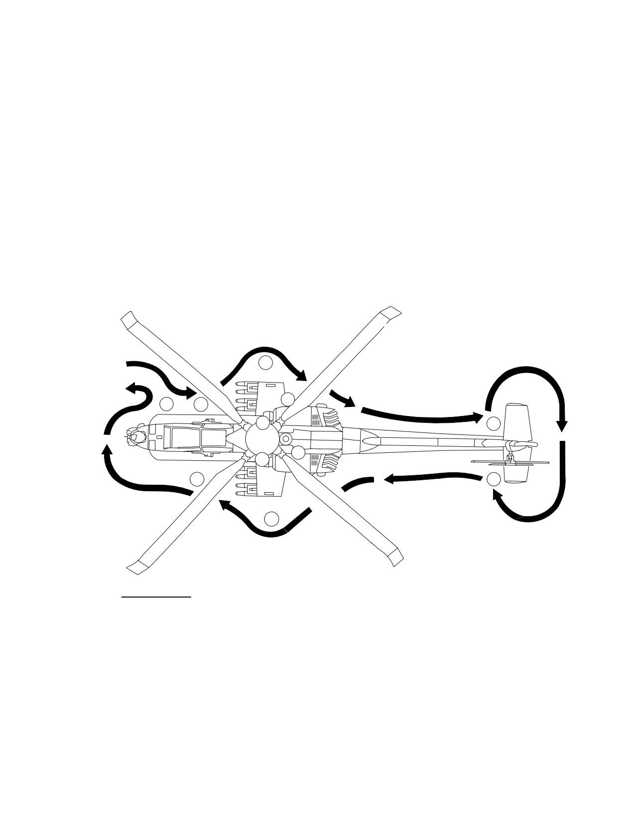
TM 1-1520-251-10
8.10 EXTERIOR CHECK
8.10.2 Right Side - Lower Center Fuselage
(Area 2).
The exterior check (fig 8-1) begins at the aircraft right side
1. Radar warning antenna - Check.
lower fuselage and proceeds in a clockwise direction
around the aircraft.
2. Extended forward avionics bay - Check.
3. Right main landing gear - Check.
8.10.1 Right Side - Underside Fuselage (Area 1).
4. Static port unobstructed - Check.
1.
30mm automatic gun and turret - Check the fol-
5. Portable fire extinguisher - Check.
lowing:
* 6. Refueling panel - Check and secure door.
a. Feed Chute - Check.
* 7. Forward gravity fuel cap secure - Check.
b. Gun condition and security - Check
* 8. Single point fuel access secure - Check.
2. Searchlight - Check.
9. Battery - Connected.
START
4
FINISH
5
1
2
3
6
8
1O
11
7
9
EXTERIOR CHECK
AREA 1
RIGHT SIDE
UNDERSIDE FUSELAGE
AREA 7
LEFT SIDE
AFT FUSELAGE/EMPENNAGE
AREA 2
RIGHT SIDE
LOWER CENTER FUSELAGE
AREA 8
LEFT SIDE
REAR CENTER FUSELAGE
AREA 3
RIGHT SIDE
MAST AREA
AREA 9
LEFT SIDE
LOWER CENTER FUSELAGE
AREA 4
RIGHT SIDE
LOWER CENTER FUSELAGE
AND WING
AND WING
AREA 10
LEFT SIDE
MAST AREA
AREA 5
RIGHT SIDE
REAR CENTER FUSELAGE
AREA 11
LEFT SIDE
LOWER CENTER FUSELAGE
AREA 6
RIGHT SIDE
AFT FUSELAGE/EMPENNAGE
AND NOSE AREA
LBA0082
Figure 8-1. Exterior Inspection Diagram
Use or disclosure of this information is subject to the restriction(s) on the title page of this document.
8-3
TM 1-1520-251-10
*8.10.3 Right Side - Mast Area (Area 3).
b. Launcher forward and aft attach lugs are se-
cure to rack and swaybrace bolts are firmly
1.
Main transmission - Check the following:
against launcher swaybrace pads - Check.
c. Electrical harness securely connected to
a. Oil level - Check.
launcher - Check.
b. Bypass indicator - Check.
d. Stores jettison quick-disconnect lanyard is
attached to electrical connector and rack -
2.
Engine nose gearbox - Check the following:
Check.
a. Oil level - Check.
e. Each missile is seated and hold-back latch
b. Oil cap secure - Check.
is locked - Check.
c. Cowling secure - Check.
f. Environmental cover - Check.
d. Engine air inlet unobstructed - Check.
NOTE
Check Load Maintenance Panel to verify
e. Oil bypass button - Check.
rocket zone loading in addition to physical
3.
Engine oil level - Check and secure door.
check.
4.
Right hand ADS probe - Check.
O
6. Rockets - Check the following:
5.
Nacelle access doors secure - Check.
a. Launcher forward and aft attach lugs are se-
cure to rack and swaybrace bolts are firmly
6.
Upper flight controls and swashplate - Check.
against launcher - Check.
7.
Main rotor head and blades - Check.
b. Launcher exterior and tube interior condi-
8.
Strap Pack - Check.
tions - Check.
9.
Inspect upper and lower sides of each main rotor
c. Electrical harness connected securely to
blade root fitting for debond/displacement, debond
launcher - Check.
repair, application of sealant, and removed or
d. Jettison quick-disconnect lanyard attached
cracked fiberglass overlay.
to connector plug and rack - Check.
8.10.4 Right Side - Lower Center Fuselage and Wing
e. Rocket loading - Check and note number
(Area 4).
and zones of rocket loading.
f. Igniter arms are rotated down and condition
1. Wing - Check.
of igniter arms - Check.
2. Pitot tube unobstructed - Check.
g. Environmental cover - Check.
3. Formation light condition - Check.
WARNING
4. Pylons - Check.
At locations where pressurized air line is
installed, ensure the smaller line is
NOTE
installed on the aft fitting of the external
When icing conditions exist, or are predicted,
fuel tank. Failure to do so could result in
and Hellfire operations are expected, the
fuel migration into the PAS manifold and
launcher ARM/SAFE switch located on each
venting into both crew stations creating
Hellfire launcher must be manually placed in
a health hazard.
the ARM position prior to liftoff. It is possible for
O
7. External fuel tanks - Check.
this switch to be rendered inoperative by icing.
8. Ammunition bay panel secure - Check.
O
5. HELLFIRE - Check the following:
9. Aft evaporator access - Check and secure door.
a. Launcher ARM/SAFE switch - As required.
10. Aft R/EFAB - Check and secure door.
Use or disclosure of this information is subject to the restriction(s) on the title page of this document.
8-4
Change 4
TM 1-1520-251-10
8.10.5 Right Side - Rear Center Fuselage (Area 5).
a. Control linkage - Check.
b. Hub - Check.
1.
Nacelle fire louvers open - Check.
c. Blades - Check.
* 2.
APU oil level - Check and secure door.
4. FM - AM whip antenna - Check.
* 3.
Aft gravity fuel cap secure - Check.
5. GPS antenna - Check.
4.
Nacelle lighting - Check the following:
6. Radar warning antenna - Check.
7. Aft tailboom - Check.
a. Anti-collision light - Check.
8.10.8 Left Side - Rear Center Fuselage (Area 8).
b. Navigation light - Check.
O
1. Chaff dispenser - Check.
5.
Aft avionics bay - Check and secure door.
2. Transmission deck catwalk doors secure -
Check.
6.
IR suppressor/engine exhaust - Check.
3. Survival equipment stowage compartment -
7.
APU exhaust - Check.
Check and secure door.
* 8.
Utility hydraulic manifold - Check the following:
4. IR suppressor/engine exhaust - Check.
5. Aft stowage bay - Check and secure door.
a. Hydraulic fluid level - Check.
6. Nacelle fire louvers open - Check.
b. Filter bypass button - Check.
7. Fire extinguisher disc visible - Check.
* 9.
Utility hydraulic accumulator - Check 2600 psi
8. Ammunition bay panel secure - Check.
minimum.
9. Aft L/EFAB - Check and secure door.
10.
Survival equipment stowage compartment -
10. Aft evaporator access - Check and secure door.
Check and secure door.
11. Nacelle lighting - Check the following:
11.
External power receptacle - Check.
a. Anti-collision light - Check.
12.
Belly antennas - Check.
b. Navigation light - Check.
8.10.6 Right Side - Aft Fuselage/Empennage (Area 6).
8.10.9 Left Side - Lower Center Fuselage and Wing
(Area 9).
1. Aft tailboom - Check.
1. Wing - Check.
2. Antennas - Check.
2. Pitot tube unobstructed - Check.
3. Formation light condition - Check.
3. Stabilator - Check.
4. Pylons - Check.
4. Tail landing gear - Check.
NOTE
8.10.7 Left Side - Aft Fuselage/Empennage (Area 7).
When icing conditions exist, or are pre-
dicted, and Hellfire operations are expected,
1. Navigation light - Check.
the launcher ARM/SAFE switch located on
each Hellfire launcher must be manually
2. Stabilator - Check.
placed in the ARM position prior to liftoff. It is
possible for this switch to be rendered inop-
* 3. Tail rotor - Check the following:
erative by icing.
Use or disclosure of this information is subject to the restriction(s) on the title page of this document.
Change 4
8-5
TM 1-1520-251-10
O
5. HELLFIRE - Check the following:
*8.10.10
Left Side - Mast Area (Area 10).
a. Launcher ARM/SAFE switch - As required.
1.
Main transmission - Check the following:
b. Launcher forward and aft attach lugs are se-
cure to rack and swaybrace bolts are firmly
a. Oil level - Check.
against launcher swaybrace pads - Check.
b. Bypass Indicator - Check.
c. Electrical harness securely connected to
launcher - Check.
2.
Primary hydraulic manifold - Check the follow-
d. Stores jettison quick-disconnect lanyard is
ing:
attached to electrical connector and rack -
Check.
a. Hydraulic fluid level - Check.
e. Each missile is seated and hold-back latch
is locked - Check.
b. Filter bypass button - Check.
f. Environmental cover - Check.
3.
Engine nose gearbox - Check the following:
NOTE
Check Load Maintenance Panel to verify
a. Oil level - Check.
rocket zone loading in addition to physical
check.
b. Oil cap secure - Check.
O
6. Rockets - Check the following:
c. Cowling secure - Check.
a. Launcher forward and aft attach lugs are se-
cure to rack and swaybrace bolts are firmly
d. Engine air inlet unobstructed - Check.
against launcher - Check.
e. Oil bypass button - Check.
b. Launcher exterior and tube interior condi-
tions - Check.
4.
Left hand ADS probe - Check.
c. Electrical harness connected securely to
launcher - Check.
5.
Engine oil level - Check and secure door.
d. Jettison quick-disconnect lanyard attached
to connector plug and rack - Check.
6.
Nacelle access doors secure - Check.
e. Rocket loading - Check and note number
7.
Upper flight controls and swashplate - Check.
and zones of rocket loading.
f. Igniter arms are rotated down and condition
8.
Main rotor head and blades - Check.
of igniter arms - Check.
O
9.
Mast mounted assembly
- Check the follow-
g. Environmental cover - Check.
ing:
WARNING
a. Derotation Unit - Check.
At locations where pressurized air line is
installed, ensure the smaller line is
b. RFI - Check.
installed on the aft fitting of the external
fuel tank. Failure to do so could result in
c. Radome/aft dome - Check.
fuel migration into the PAS manifold and
venting into both crew stations creating
d. Locking pin - As desired.
a health hazard.
O
7. External fuel tanks - Check.
10.
Strap pack - check.
Use or disclosure of this information is subject to the restriction(s) on the title page of this document.
8-6
Change 3
TM 1-1520-251-10
8.10.11 Left Side - Lower Center Fuselage and Nose
8.
CHOP button - Guard down.
Area (Area 11).
9.
STORES JETTISON Panel - Check.
1. Canopy - Check.
* 10.
POWER levers - OFF.
2. CANOPY JETTISON pin removed and stowed -
Check.
11.
Engine START switches - OFF.
3. FAT gauge extension secure - Check.
* 12.
RTR BRK - OFF.
4. Static port unobstructed - Check.
13.
EMERGENCY Panel - Check:
5. AWS hydraulic accumulator - Check (55 psi).
a. EMER HYD - OFF.
6. Left main landing gear - Check.
b. ZEROIZE - Check in aft position.
7. Static ground cable - Check.
14.
NVS MODE switch - OFF.
8. Extended forward avionics bay - Check.
* 15.
CANOPY JETTISON pin removed and stowed -
Check.
9. Radar warning antenna - Check.
16.
Video panel - Check.
NOTE
17.
MASTER ZEROIZE switch - Guard down and
When icing conditions exist, ensure that
lockwired (0.020 copper).
TADS/PNVS gear teeth are free of ice.
18.
Standby flight instruments - Check:
10. TADS/PNVS turrets - Check.
a. Attitude indicator - CAGE.
8.11
INTERIOR CHECK - PILOT
* 1. Canopy door - Check, then as desired.
b. Airspeed Indicator - Check.
* 2. Loose equipment - Secured.
c. Altimeter - Check.
3. Seat adjusted to design eye position - Check.
d. Magnetic Compass - Check.
* 4. Restraint harness - Fasten and adjust.
19.
DTC installed and door secured.
5. Inertia reel lock - Check.
20.
COMM panel switches - As desired.
6. Pedals - Check and adjust.
* 21.
HDU - Check and adjust as required.
* 7. PARK BRAKE - Set.
22.
WIPER control - OFF.
Use or disclosure of this information is subject to the restriction(s) on the title page of this document.
Change 2
8-7
TM 1-1520-251-10
* 8.12
BEFORE STARTING APU - PILOT
b. UFD/EUFD - Monitor.
3. MSTR IGN switch - BATT (if external power
CAUTION
was used).
To prevent heat damage to the System
4. External power disconnected - Check, advisory
Processor (SP), the APU must be started
extinguished.
within one minute of the initiation of bat-
* 8.14
AFTER STARTING APU - PILOT
tery operations when FAT is > 43 °C, with-
in three minutes when FAT is between 32
1. Canopy door - Closed.
°C and 43 °C, and within 20 minutes
when FAT is < 32 °C.
2. EXT LT/INTR LT panel - As desired.
1.
MSTR IGN switch - BATT (EXT if external pow-
3. KU, MPD, and UFD/EUFD knobs - As desired.
er is to be used).
4. ECS system - Verify air flow and set tempera-
2.
Searchlight - As required.
ture as desired.
3.
Utility light - As desired.
NOTE
4.
TAIL WHEEL button - Verify locked.
Some thru - flight data will be lost unless the
5.
ICS system - Check.
THRU-FLIGHT button is selected within
one minute of power up.
6.
EXT LT/INTR LT panel PRESS-TO-TEST but-
ton illuminates all signal lights - Check.
5.
DTC - Select load.
7.
MSTR WARN, MSTR CAUT, and UFD/EUFD -
6.
EGI - Verify keys as required.
Check.
7.
FLT SET page - As desired for the following:
8.
FIRE DET/EXTG panel TEST switch - Test as
follows:
a. Altimeters - Set to field elevation or current
QNH barometric pressure.
a. Position 1: - MSTR WARN, ENG 1, APU,
and ENG 2 FIRE buttons are illuminated
and voice warning system is activated.
b. RAD ALT - Set HI/LO as desired.
[
BLK 1
DECK FIRE (UFD)]/[
BLK 2
8.
DMS Menu page - Systems configuration - As
AFT DECK FIRE (EUFD)] warning mes-
required for mission:
sage appears.
b. Position 2: - MSTR WARN, ENG 1, APU,
a. Mission subsystem pages - Configure.
and ENG 2 FIRE and DISCH buttons are il-
luminated and voice warning system is acti-
b. Aircraft subsystem pages - Configure.
vated.[
BLK 1
DECK FIRE (UFD)]/[
BLK 2
AFT DECK FIRE (EUFD)] warning
c. Communications subsystem pages - Con-
message appears.
figure.
* 8.13
STARTING APU - PILOT
d.
[
BLK 2
ELT check - Perform.]
WARNING
L 9. IHADSS boresight - Perform.
To prevent injury to personnel, ensure
pylons/stabilator are clear prior to start-
L 10. NVS operational check - As required.
ing APU.
L 11. FCR
Operational check (may be performed
1. Fire guard (if available) - Posted. APU
by the CPG) - As required.
exhaust area clear.
L 12. Weapons Operational Checks - As required.
2. APU - Start as follows:
a. APU push button - Press.
L 13. ASE Operational Checks - As required.
Use or disclosure of this information is subject to the restriction(s) on the title page of this document.
8-8
Change 2
TM 1-1520-251-10
WARNING
CAUTION
Do not start engines with BUCS en-
The Pilot will ensure that both EGIs have
gaged. BUCS can become engaged
aligned properly and are displaying the
when a mistrack between the controls
same position, attitude and heading,
and the actuator is sensed. This com-
POSITION CONFIDENCE values, valid
monly happens when external power is
DATE, TIME and GPS tracking. This will
applied to the aircraft without hydraulic
prevent the erroneous velocity data sig-
power. BUCS engagements may be
nals from the EGIs being sent to the
cleared by applying hydraulic power and
Flight Management Computer (FMC),
completing a FLT CNTRLS IBIT.
which should prevent an uncommanded
scheduling of the Stabilator.
* 8.15
BEFORE STARTING ENGINES - PILOT
* 8.17
EGI OPERATIONAL CHECK - PILOT/CPG
1. NVS MODE switch - As desired.
1. TSD and FLT page - Select.
2. Standby attitude indicator - Uncaged.
2. Verify heading, attitude and position.
3. A/C (ENG) (SYS) page - Check.
3. TSD UTIL page - Select. Note current POSI-
TION CONFIDENCE value, verify current DATE
4. ENG page - Check.
and TIME.
5. Perform control sweep and trim check.
4. HDU - Verify normal velocities.
5. Secondary EGI - Select as PRIMARY. Note
* 8.16
BUCS TEST - PILOT/CPG
POSITION CONFIDENCE value, verify current
1. RTR BRK switch - BRK.
DATE and TIME.
6. FLT page - Verify heading and attitude.
2. Collective friction - OFF (both crewstations).
7. HDU - Verify normal velocities.
3. Stabilator Area - Check clear.
8. TSD page - Select.
4. POWER levers - OFF.
9. PP button - Select. Verify position.
5. DMS IBIT page - Select.
10. TSD UTIL page. Select EGI with lowest POSI-
TION CONFIDENCE value as primary.
NOTE
NOTE
Maintenance action is required after two
consecutive failures of the Flight Controls
If one or both of the EGIs displays a position
IBIT.
error greater than one nautical mile from the
aircraft’s known position or if the DATE and
6. ACFT/COM - FLT CNTRLS - PRFLT - Select.
TIME is incorrect, perform the on ground
Follow IBIT instructions until test is complete.
manual reset and alignment procedure.
Longitude and latitude are displayed in de-
7. RTR BRK switch - OFF.
grees, minutes and 100ths of minutes; one
8. Flight Controls - Adjust as required.
minute equates to approximately one mile.
Use or disclosure of this information is subject to the restriction(s) on the title page of this document.
Change 4
8-9
TM 1-1520-251-10
* 8.18 ON GROUND MANUAL RESET AND
CAUTION
ALIGNMENT PROCEDURES
• If engine 1 or 2 start advisory remains
1. Current position - load into KU.
displayed after 66% - 68% NG: Position
ENG START switch to IGN ORIDE,
2. INU1 and INU2 - Reset. Check TSD page for
then OFF.
the HDG selection displayed.
•
Prior to advancing POWER levers, en-
3. PSN - Select.
sure that both engines are stabilized
(NP , NG , Torque% and Oil PSI).
4. POS - Select.
• While advancing POWER levers to
FLY, ensure that both engines indicate
5. KU ENTER button - Press.
a rise in TORQUE% to confirm that the
sprag clutches are engaged.
NOTE
• If an engine indicates near 0% TOR-
If HDG selection is not displayed or is re-
QUE, retard POWER lever of affected
moved while the current position data is be-
engine to OFF.
ing entered, perform an INU1 and INU2 re-
• TGT must be less than 150° C
or
set and then quickly (within one minute)
80° C
before moving power lever
re-enter the current position.
to IDLE.
L 5. First Engine - Start as follows:
6. UPT - Select.
a.
Normal Start (COLD ENGINE - 4 hours
7. TIME - Select. Enter current Zulu time.
since last shutdown).
(1) START switch - START.
8. DATE - Select. Enter current Zulu date.
(2) POWER lever - IDLE, at first indication
* 8.19
STARTING ENGINES - PILOT
of NG increase.
(3) ENG OIL PRESS - Monitor.
(4) TGT - Monitor.
CAUTION
(5) NG - Monitor.
The T700 - GE - 701C
engine exhibits
(6) MSTR WARN, MSTR CAUT, and UFD/
inconsistent starting capability above
EUFD - Monitor.
6000 feet density altitude (inflight and
b.
Normal Start (WARM ENGINE
- Less
ground). Starts above this density alti-
than 4 hours since last shutdown. Inflight re-
tude may be unsuccessful and require
starts do not need to utilize a warm start pro-
an abort because of exceeding tempera-
cedure).
ture limits.
(1) START switch - IGN OVRD. Allow NG
1. Area - Clear.
speed to increase to 18 to 20% then
OFF. Once the first engine is placed to
2. Fire guard (if available) - Posted.
the OFF position, motoring of the sec-
ond engine is permitted.
(2) START switch - START after NG de-
CAUTION
creases below 5%.
During a rotor brake lock start, if rotor
CAUTION
blades begin to rotate: Set RTR BRK
switch to - OFF.
TGT must be less than 150° C
or
80° C
before moving power lever to
3. RTR BRK switch - OFF or LOCK.
IDLE.
4. EXT LT - As required.
(3) POWER lever - IDLE.
Use or disclosure of this information is subject to the restriction(s) on the title page of this document.
8-10
Change 2