Network Intrusions Responder Program (NITRO). Instructor Guide - page 12
Network Intrusion Responder Program
Appendix D
Hard Drive Preparation, continued
Ext3, continued
Volumes using the ext2 file system can easily be converted to the
ext3 standard with one command using the tune2fs program.
Partitions do not have to be removed and recreated; rather the
journal system is updated to the ext3 format without the loss of
any data. Like ext2, the ext3 file system can manage partitions up
to 16 terabytes in size.
Reiser
The Reiser file system has some similarities with the extended file
systems. For instance, it can address a partition up to 16 terabytes
in size. However, Reiser is considered a more robust file system.
Like ext3, Reiser takes advantage of journaling for greater file
reliability.
Reiser also provides the capability of online resizing. This allows
the file system to automatically extend the size of the partition as
needed. It only allows for extending the partition and not shrinking
the partition. Although there are tools to allow both growing and
shrinking of the file system while offline.
Development for Reiser version 3 has been stopped to focus
development efforts to the next version of Reiser, version 4.
Ext4
The Ext4 file system is still currently under development. Some of
the primary improvements are:
Supports volume sizes of up to 1 exabyte
Support large file sizes up to 2 terabytes
Ability to undelete files
Extents - A continuous area of storage reserved for a file
Persistent file preallocation
Online defragmentation
D-32
For Official Use Only - Law Enforcement Sensitive
01/09

Appendix D
Network Intrusion Responder Program
Hard Drive Preparation, continued
Linux Drive
The drive identification process in Linux differs for the FAT or
Identification
NTFS environment. Identification values are assigned based on
how the device is connected to the motherboard, its jumper
settings, and its relationship to the other storage devices.
File System
The following chart represents common operating systems and the
Compatibilities
file systems supported by each.
Operating System
FAT16
FAT32
NTFS
Reiser
Ext2/3
Windows 95
Y
N
N
N
Windows 95 b,c
Y
Y
N
N
Windows 98 / 98 SE
Y
Y
N
N
Windows ME
Y
Y
N
N
Widows NT
Y
N
Y
N
Windows 2000
Y
Y
Y
N
Windows XP / Vista
Y
Y
Y
N
Linux
Y
Y
R/RW
Y
Note: Linux natively has the ability to read an NTFS file system.
However, most current Linux distributions preinstall
modules like NTFS-3G, which provide read-write
functionality.
Key:
= native file system
01/09
For Official Use Only - Law Enforcement Sensitive
D-33
Network Intrusion Responder Program
Appendix D
This page intentionally left blank.
D-34
For Official Use Only - Law Enforcement Sensitive
01/09
Appendix D
Network Intrusion Responder Program
Lesson 2 - Floppy Drives and Removable Media
Introduction
This lesson examines types of floppy disk drives and a variety of
removable media storage components.
Purpose of this
Understanding data storage components of a computer system is
Lesson
important to knowing how to safeguard information that is seized
during a crime investigation.
Objectives
After successfully completing this lesson, you will be able to:
Identify the characteristics of floppy disk drive components
Explain the characteristics of a magnetic drive
Recognize common removable media
Explain the characteristics of a magneto-optical drive
Name the differences between magnetic and digital audio tapes
(DAT)
In this Lesson
The following table shows the contents of this lesson.
Topic
See Page
Floppy Disk Drives
D-36
Removable Media
D-38
01/09
For Official Use Only - Law Enforcement Sensitive
D-35
Network Intrusion Responder Program
Appendix D
Floppy Disk Drives
Floppy Disks
Floppy disks are storage devices used to move information from
one system to another and to make file backups. There are two
different types of floppy disks available:
5.25-inch Disk
This disk is a double-sided, high-density disk. They have 80 tracks
with 15 sectors per track; 4 KB clusters, and either 420 KB or 1.2
MB of storage. They are nearly obsolete but may be found in older
systems dated before 1994.
3.5-inch Disk
Most PCs today use 1.44 MB 3.5 inch disks for data transfer and
backup, though their integration in newer computers is becoming
rarer. These disks are encased in a hard plastic shell and come in
three density types:
1. Double Sided/Extra High Density: 80 tracks; two sides, 36
sectors per track, 4 KB clusters; 2.88 MB of storage space.
2. Double Sided/High Density: 80 tracks; 2 sides, 18 sectors per
track, 4 KB clusters; 1.44 MB of storage space.
3. Double Sided/Double Density: 80 tracks; 2 sides, 9 sectors per
track, 4 KB clusters; 720 KB of storage space.
D-36
For Official Use Only - Law Enforcement Sensitive
01/09
Appendix D
Network Intrusion Responder Program
Floppy Disk Drives, continued
Floppy Drive
Today, most floppy drive controllers are now found on the Super
Controllers
I/O chip. In the past, the floppy disk controller was found on a
separate ISA slot card. Characteristics of floppy drive controllers
include the following:
Connected to the MB for data input/output via a 34-pin ribbon
cable that has a twisted segment to differentiate drive A from
drive B. Unlike the controller connections for a hard drive, a
floppy controller has no standard location for pin 1. Some
drives locate pin 1 close to the power connector while others
place it away from the power connector.
Modern transfer rate has been standardized to approximately 1
Mb/sec.
01/09
For Official Use Only - Law Enforcement Sensitive
D-37
Network Intrusion Responder Program
Appendix D
Removable Media
Removable Media Floppy drives have become almost completely replaced by other
forms of removable media that can store large amounts of data.
This trend began with devices such as ZIP drives and LS 120
drives, and continues now with flash drives. Removable media can
be divided into several categories: magnetic media, magneto-
optical media, DVDs, CD-ROMs, USB flash drives, and external
drives.
Magnetic Media
Magnetic drives include the SyQuest drives and Iomega ZIP
Drives
drives.
SyQuest Drives
Uses 5.25 inch and 3.5 inch disk cartridges that use a rigid
platter housed in a plastic cartridge
Disk capacity: 5.25 inch disk holds 44 MB and 88 MB and 3.5
inch disk holds 105 MB and 270 MB
Used with ATAPI and SCSI interface models
Drives are not widely used but may be found in older computer
systems
Iomega ZIP Drives
Uses a proprietary disk format, which is a 3.5 inch disk
cartridge with a flexible platter housed inside a plastic
cartridge. These disks are about twice as thick as 3.5 inch
floppy.
Disk capacity is 100 MB, 250 MB, and 750 MB
External models use SCSI, parallel, and USB interfaces and the
internal models use SCSI or ATAPI interfaces
Iomega ZIP drive and cartridge
D-38
For Official Use Only - Law Enforcement Sensitive
01/09
Appendix D
Network Intrusion Responder Program
Removable Media, continued
Magneto-optical
Magneto-optical drives provide magnetic, high density storage.
Drives
Data is written to these drives by a precise laser beam that heats a
tiny spot in the disk’s alloy to the Curie point of 300 degrees. This
action allows the molecules to be realigned when subjected to the
magnetic field located on the opposite side of the disk.
To read stored data on the drive, the weaker laser beam is used to
focus on the tracks. The crystals in the alloy polarize the light from
the laser. This reflective beam is read by a photodiode that
translates the reflective light to ones and zeros. This data is then
passed on.
Super Floppy or Floptical Drive
The LS-120 drive, known as the super floppy or floptical, can store
twenty times more data than a conventional floppy. Most super
floppies hold 120 MB of data on a 3.5-inch disk and Sony has a
200 MB model. It is nearly identical in appearance to the standard
floppy disks and can read/write to floppy disks. It was developed
by 3M, O.R. Technologies, and Mastushita-Kotobuki Industries
and uses the same ferrite materials common to floppy drives.
Floptical drives use a special optical mechanism to align the
magnetic read/write heads over the data tracks. The servo track
information that the laser uses to guide the read/write heads is
etched into the disk by the manufacturer.
If you format a floptical disk in a standard floppy drive you will
reduce storage capacity because the disk will be formatted with the
standard 1.44 MB. These drives may be found in ATAPI and SCSI
systems.
01/09
For Official Use Only - Law Enforcement Sensitive
D-39
Network Intrusion Responder Program
Appendix D
Removable Media, continued
Tape Drives
Tape drives are used primarily to backup entire systems. Tape
drives come with their own proprietary software and newer models
have ATAPI and SCSI interfaces. The two types of tape storage
include magnetic tapes and digital audio tape (DAT).
Magnetic Tape Storage
Operate much like the old reel-to-reel recording systems
Manufactured in two sizes: 1) data cartridge (6 inches by 4
inches by 0.675 inch) 2) mini cartridges (3.2 inches by 2.4
inches by 0.4 inch) are more widely used than the data
cartridges
Stores from 2 GB to over 500 GB of data
DAT Storage
Records in a digital format using magnetic technology
Tape size is a little smaller than a cassette tape
Available in two primary formats: 1) 4mm cartridge that stores
up to 36 GB of uncompressed data and 2) 8mm cartridge that
stores up to 80 GB of uncompressed data
A third format, Digital Linear Tape (DLT), stores between 35
GB and 800 GB of data and is only used with high-end data
servers
D-40
For Official Use Only - Law Enforcement Sensitive
01/09
Appendix D
Network Intrusion Responder Program
Removable Media, continued
Compact Disc
CD-ROM is a disc format used to hold text, graphics and hi-fi
Read Only
stereo sound. It is very similar to an audio CD, but uses a different
Memory (CD-
format for recording data. An audio CD player cannot play CD-
ROM)
ROMs, but CD-ROM players can play audio discs.
How Data is Stored on CD-ROM
Information is stamped into the disc when manufactured as a series
of pits and lands. The pits are the small raised areas in the tracks
on the CD-ROM separated by flat spaces (lands). The back of the
CD-ROM is a highly reflective surface. When the laser beam
shines up through the disc, the light is reflected back. When the
light hits the edge of a pit, the light is not reflected back. When the
light hits a land, the light is reflected back. The microprocessors in
the drive translate the light and dark transitions as 1s and 0s.
Compact Disc
CD-R is a form of CD-ROM technology that writes to a disc. Each
Recordable
disc can be written to only once. A CD-R drive cannot stamp pits
(CD-R)
into the disc. Instead, it uses a layer of dye to simulate the pits and
lands. To record, the laser burns the dye to simulate pits and does
not burn areas for lands. To read, the laser beam is reflected back
from the non-burnt areas (lands) and is not reflected back from the
burnt areas (pits). The drive interprets both.
Compact Disc
Unlike a CD-R that can only be written to once, a CD-RW can
Re-writable
record, erase, and re-record data on the same disc up to 1,000
(CD-RW)
times. Instead of stamped pits or dye, CD-RWs use a phase change
technology that involves a crystalline layer. The process uses a
high intensity laser pulse that turns the crystalline natural state
(reflective) to an amorphous one (dull). When the disc is read, it
uses this dull/reflective state to simulate the pits and lands. To
erase and re-record data, CD-RW uses a medium intensity pulse to
restore the crystalline surface to a reflective state.
01/09
For Official Use Only - Law Enforcement Sensitive
D-41
Network Intrusion Responder Program
Appendix D
Removable Media, continued
DVD Introduction DVD is commonly termed Digital Video Disc as a means to
describe the technology. However, a DVD is far more capable than
just storing and playing digital video.
DVD is a group of disk formats that store data, video, or audio
information with capacities between 4.7 GB and 8.54 GB. A DVD
is generally a disk that is 120 mm in diameter and 1.2 mm thick.
Reflective surfaces embedded in polycarbonate resin hold data as
pits and lands in tracks that are much smaller and closer together
than those on a CD. All DVD drives feature backward
compatibility to read CD media.
DVD-ROM
Data, be it audio, video, or software, is molded into the disk when
manufactured. Unlike CD media, DVD media has its reflective
data layer more deeply protected in the structure of the disk.
User-Recordable
Data is written or “burned” into a disk by the user with a write
DVD
capable drive. Currently, there are six different formats of writable
DVD. You must use compatible media in the appropriate drive to
make a recording. Once written, all DVD disk types (except DVD-
RAM) can be read in other DVD drive types.
D-42
For Official Use Only - Law Enforcement Sensitive
01/09
Appendix D
Network Intrusion Responder Program
Removable Media, continued
Recordable DVD
Media Types
DVD-RAM
Once formatted, this disk together with its drive
can be treated as if it were a hard disk drive.
Re-writable up to 100,000 times. For more
capacity, use another blank disk.
DVD-R
Write-once, read many times
DVD-RW
Re-writable up to 1,000 times
DVD+R
Write-once, read many times
DVD+RW
Re-writable up to 1,000 times
DVD+R DL
Dual layer write once, read many times
Note: Drive types are typically grouped as DVD-R/RW/RAM,
or DVD+R/RW/DL.
DVD Capacity
The table below lists a comparison of DVD capacities.
Comparison
Format
Capacity
Type
Single Sided,
4.7 billion bytes
“DVD-5”
Single Layer
Single Sided, Dual
8.5 billion bytes
“DVD-9”
Layer
Double Sided,
9.4 billion bytes
“DVD-10”
Single Layer
Double Sided,
17 billion bytes
“DVD-18”
Dual Layer
HD-DVD and
Introduced in 2006, HD-DVD and Blu-ray are two rival High
Blu-ray
Density DVD formats. Each format is backed by competing
groups of equipment manufacturers.
HD-DVD has a data capacity of 15 GB for single-layer disks and
30 GB for dual-layer disks. In late 2007 a new format was
approved, allowing for three layers to store a capacity of 51 GB.
Blu-ray disks can hold 25 GB for single layer disks and 50 GB for
the dual-layer disks. Laboratory tests have successfully tried up to
eight layers for a total of 200 GB per disk.
01/09
For Official Use Only - Law Enforcement Sensitive
D-43
Network Intrusion Responder Program
Appendix D
Removable Media, continued
USB Flash Drives Flash drives are mass storage devices that allow you to transport
files between devices. Flash drives offer a very compact, non-
volatile storage option for data. The transfer rate of data is
dependent on the type and speed of interface used for the device.
USB Flash Drives
Small, easily transported, and rewritable
Uses USB 1.0, 1.1, or 2.0
Stores up to 64 gigabytes
Memory Cards
Memory cards are flash memory storage devices that are common
in many electronic devices. Some devices that may support
memory cards are: digital cameras, cell phones, portable audio
devices, game consoles, mobile computers, etc. The large storage
capacities and small footprints make this storage technology an
excellent companion to many portable electronic devices.
Compact Flash - Introduced by Sandisk in 1994. With storage
capacities up to 64 GB, these are commonly found in digital
cameras or mini hard drives. Available in two variations: Type I
and Type II.
Secure Digital (SD) - Developed by Sandisk, Matsushita, and
Toshiba. Secure Digital format supports up to 16 GB of storage
and up to 32 GB with high-capacity SDHC cards.
MiniSD - Provides storage capacities up to 4 GB. These devices
can be used in a typical SD slot with the use of an adapter. High-
capacity MiniSDHC cards can provide for up to 32 GB of space.
MicroSD - These cards are about the size of a penny and provide
storage capacities up to 8 GB. These cards can be used in the
larger SD and MiniSD slots with the use of an adapter. A high
capacity implementation, microSDHC, allows for capacities up to
32 GB.
Memory Stick - This memory is developed by Sony. The term
“Memory Stick” can refer to the whole memory stick lineup of
products. These include the Memory Stick Pro, memory Stick
Duo/Pro Duo, Memory Stick Micro, and Memory Stick Pro-HG.
D-44
For Official Use Only - Law Enforcement Sensitive
01/09
Appendix D
Network Intrusion Responder Program
Removable Media, continued
External Drives
External drives are available in USB, FireWire, and eSATA.
These drives are hot swappable and easily transported from one
system to another.
USB and FireWire connections are recognized by operating
systems such as Windows XP and many versions of Linux.
The eSATA has a special adapter and cable, which eliminates the
protocol issues of converting the drive’s native signal to the serial
port adapter. This allows higher transfer rates, but restricts the
portability of the drive to computers equipped for eSATA.
01/09
For Official Use Only - Law Enforcement Sensitive
D-45
Network Intrusion Responder Program
Appendix D
This page intentionally left blank.
D-46
For Official Use Only - Law Enforcement Sensitive
01/09
Appendix E
Network Intrusion Responder Program
Appendix E
Input/Output Components
Overview
This module examines the various components involved in the
transfer of data into and out of a computer system.
Purpose of this
The purpose of this lesson is to introduce the data transfer
Module
components of computer systems. Student will also be taught how
the various components interact in order to move data.
Objectives
After successfully completing this module, you will be able to:
Recognize basic input devices such as the keyboard, mouse,
scanner, and modem
Explain how monitors and video display adapters work
Identify the various input/output ports found on a PC
Define interrupts, IRQs, direct memory access, and device
drivers
Recognize SCSI devices and connectors
In this Module
The following table shows the contents of this module.
Topic
See Page
Lesson 1 - Input/Output Devices and Ports
E-3
Lesson 2 - BIOS and System Initialization
E-23
01/09
For Official Use Only - Law Enforcement Sensitive
E-1
Network Intrusion Responder Program
Appendix E
This page intentionally left blank.
E-2
For Official Use Only - Law Enforcement Sensitive
01/09
Appendix E
Network Intrusion Responder Program
Lesson 1 - Input/Output Devices and Ports
Introduction
This lesson introduces the basic input/output devices including the
keyboard, mouse, scanner, monitor, printer, and modem.
Purpose of this
You will gain a broader understanding of common input/output
Lesson
components and how they work.
Objectives
After successfully completing this lesson, you will be able to:
Recognize input devices such as the keyboard, mouse, scanner,
and modem
Explain how monitors work and be familiar with video display
adapters
Identify the various input/output ports
In this Lesson
The following table shows the contents of this lesson.
Topic
See Page
Input/Output Overview
E-4
Input Devices
E-5
Output Devices
E-8
Input/Output Ports
E-13
Modems
E-19
PC Cards
E-21
01/09
For Official Use Only - Law Enforcement Sensitive
E-3
Network Intrusion Responder Program
Appendix E
Input/Output Overview
Overview
Most of the hardware components found on a PC can be
categorized as either an input or an output device. Modems are the
exception because they transmit and receive information. Devices
included in each category are:
Input Devices
Keyboard
Mouse and other pointing devices
Game controllers
Scanners
Output Devices
Monitors
Video Adapter Cards
Printers
E-4
For Official Use Only - Law Enforcement Sensitive
01/09
Appendix E
Network Intrusion Responder Program
Input Devices
Input Devices
A computer system includes several data input devices. Those
defined here include the keyboard, pointing devices, and scanner.
Keyboard
The keyboard is the primary input component for using a
computer. Many new features have been added to the keyboard in
recent years such as additional short cut keys. However, the basic
way a keyboard works remains the same since the first IBM PC in
the early 1980s.
There are many styles of keyboards with various built-in functions
including pointing devices such as trackballs and special keys that
are programmed to launch programs or Web sites.
How Keyboards Work
In brief, the keyboard works using a grid of embedded circuits
called the key matrix. When a key is pressed, the change in current
in the circuit that is associated with the key is picked up by the
keyboard‟s microprocessor. The microprocessor generates a scan
code that is read by the computer‟s BIOS. The BIOS translates the
scan code into ASCII code, which is then recognized by the
application software, such as word processing software.
Pointing Devices
Computer pointing devices come in many shapes and sizes. All are
used to control a computer by pointing to images instead of using
the keyboard to type commands. The mouse was the first device
developed by Xerox in the early 1980s and remains the standard.
Other current devices include the touchpad, trackball, trackpoint,
and game controller.
Mouse
The mouse is the standard pointing device used to navigate your
system‟s graphical user interface (GUI). In short, the internal
electronics of the mouse sends signals through the attached cable
to the computer‟s operating system. The operating system then
translates the signal to move the onscreen cursor.
01/09
For Official Use Only - Law Enforcement Sensitive
E-5
Network Intrusion Responder Program
Appendix E
Input Devices, continued
Pointing Devices,
Touchpad
continued
The touchpad is a fixed pointing device that uses the movement of
a finger on the touch-sensitive pad to control the location of the
cursor in the GUI. It replaces a standard mouse in laptop and
notebook computers where space is limited. It is also known as the
glidepoint.
Trackball
The trackball is basically an inverted mouse with the ball located
on the outside of the housing. It contains the same connectors as
found in a standard mouse.
Trackpoint
The trackpoint, also called a pointing stick, is a small rubber
component embedded in the keyboard between the G and H keys
on a laptop computer. To operate it, you move the stick to move
the cursor.
Gyroscopic Mice
Gyroscopic mice feature gyroscopes to detect movement while the
mouse is moved in mid-air. Such mice are normally shaped similar
to remote controls and allow for wireless control of a computer
from long distances. They are commonly used for conference
room and home theater computers.
Game Controllers Game controllers, also called joysticks, are available in a wide
variety of designs such as steering wheels, flight simulator
controls, and pressure pads. All are input devices for game
software. The joystick has an upright stick that controls movement
by providing the X-Y axis coordinates of the stick.
Joysticks come in digital or analog compatible formats. They
connect through game ports or the USB port. The more expensive
controllers can be programmable with macros to allow specific
series of actions or commands to be transmitted with a single
button.
E-6
For Official Use Only - Law Enforcement Sensitive
01/09
Appendix E
Network Intrusion Responder Program
Input Devices, continued
Scanner
Scanners are used to translate text or pictures into a digitized form
the computer can read and store. All scans are delivered to the
computer as a digital image. Scanned pictures are code that can be
used by a graphics software program. Printed type can be
converted into editable text when scanned using optical character
recognition (OCR) software.
There are three main types of scanners:
1. Hand-held scanners: Offer low resolution, 200-400 dots-per-
inch (DPI), with 8-bit imaging. The scan window is only five
to seven inches wide. Therefore, wide images require image re-
sectioning.
2. Flatbed scanners: Provide photo quality resolution. Typed
sheets and pictures are placed facedown on the large scan
window. Advantages include high resolution and the ability to
scan thick documents such as books. These scanners usually
come with their own proprietary image processing software.
3. Sheet-fed scanners: Scan one standard-size sheet at a time.
Resolution can be the same as flatbed scanners.
01/09
For Official Use Only - Law Enforcement Sensitive
E-7
Network Intrusion Responder Program
Appendix E
Output Devices
Output Devices
A computer system includes several data output devices. The
following describes output devices including monitors, video
display adapters, and printers.
Monitors
The main video display components of a PC include the monitor
and the video adapter, also known as a video card. A monitor
refers to the display screen. Monitors are classified by the
following criteria:
Diagonal screen size measured in inches. Desktop PC monitors
range in size from 14 inches to over 40 inches and LCDs in
laptops generally range from 6 inches to 21 inches. Monitors
are usually evaluated on two prime factors: size and resolution.
Display resolution measured in pixels
Refresh rate ranging from 60 Hz to 100 Hz
Monitor Technologies
The three types of monitor technologies are:
Cathode ray tube (CRT) monitor: Most common type of
monitor for desktop systems until the early 2000s.
Liquid crystal display (LCD) monitor: Used in laptops as well
as high-end desktop monitors.
Organic Light Emitting Diode (OLED) monitor: Used in
laptops as well as desktop monitors.
E-8
For Official Use Only - Law Enforcement Sensitive
01/09
Appendix E
Network Intrusion Responder Program
Output Devices, continued
Benefits of CRT
While the sales of CRT monitors have decreased dramatically in
Monitors
recent years, they still hold a few major advantages over LCD
monitors. The color display on CRT monitors is dramatically
better than LCD, providing a greater color range and depth, which
is beneficial to graphic artists. LCDs also suffer from blurring
during fast motion, and slower response times in redrawing the
screen. These two issues make high-performance CRT monitors
beneficial to avid gamers.
CRT Monitor
Resolution of a monitor is measured by pixel density. The more
Resolution
pixels it has, the clearer the image. Pixel density is expressed in
dots per inch (DPI). Other notable resolution characteristics of
monitors include the following:
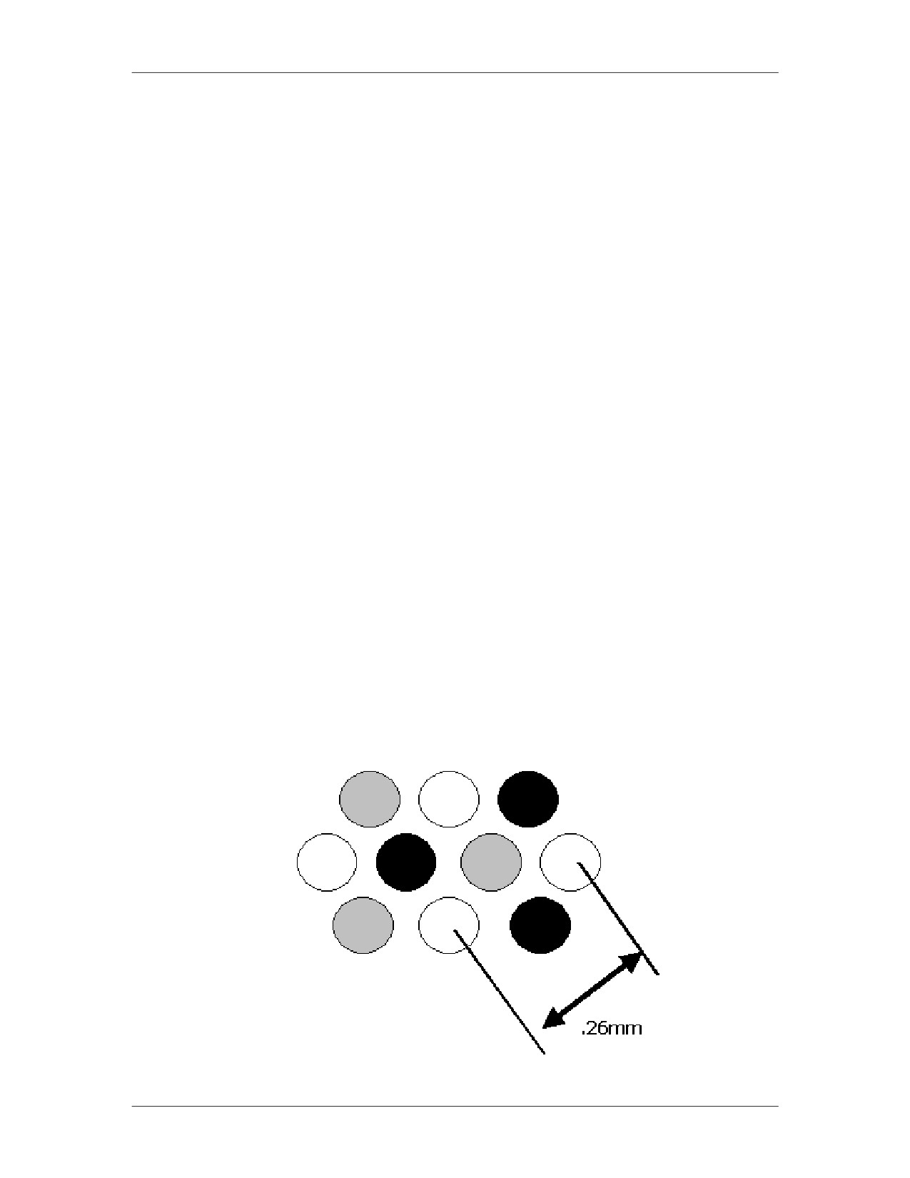
Dot Pitch: The dot pitch is the distance in millimeters between
the same color phosphor dots/squares on the screen. The less
the distance between dots, the higher the screen resolution.
Likewise, the smaller the dot pitch, the greater the clarity. For
example, an average resolution is approximately .28 mm,
whereas a high resolution is .26 mm or less.
Refresh Rate: Speed at which a monitor completes drawing the
screen. The speed is measured in Hz. The higher the refresh
rate, the sharper the image will be with less screen flicker. The
minimum PC refresh rate is 60 times per second.
Example of Dot Pitch
01/09
For Official Use Only - Law Enforcement Sensitive
E-9
Network Intrusion Responder Program
Appendix E
Output Devices, continued
Monitors: Liquid
LCD monitors are found in calculators, handheld devices,
Crystal Display and
televisions, PCs, and notebook computers. LCDs produce
Organic Light
different colors on the screen by using a combination of filters
Emitting Diode
and electrically charged liquid crystal cells to filter and change
the angle of the light passing through the panel. Transistors
electrically charge the crystals. The number of crystals used is
proportional to the number of pixels the screen can display.
LCDs generally use less power than their CRT counterparts.
However, they are more expensive to manufacture than CRT‟s
and do not have the same clarity, contrast ratio, or response time.
There are two categories: passive matrix and active matrix LCDs.
Passive Matrix LCDs
A passive matrix screen has transistors along the edge of the
screen that are connected by conductors. The intersection of
conductors forms a pixel. If the screen has 1,024 x 768 pixels,
there are 1,024 transistors along the horizontal edge and 768
transistors along the vertical edge to electrically charge the
crystals. By placing the transistors along the edge of the screen,
passive matrix LCD monitors are less bright and cheaper to
manufacture than active matrix monitors.
Active Matrix LCDs
Active matrix LCD monitors use the same system of filters and
liquid crystal to create the image as passive matrix LCDs, but
have a transistor for every pixel. As a result, active matrix LCDs
require a greater number of transistors. For example, a resolution
of 1,024 x 768 requires 1,892 transistors for a passive matrix
monitor and 786,432 transistors for an active matrix monitor. The
active matrix monitors provide greater clarity and brightness.
Organic Light Emitting Diode (OLED) Monitors
OLED monitors are a newer evolution of LCDs. Unlike LCDs,
they do not require a backlight to display pixels, therefore greatly
reducing power requirements. Organic LEDs have an organic
substrate that glows when you put an electric current behind it.
The material used is also quite flexible, allowing for its use in
unique applications, such as clothing.
E-10
For Official Use Only - Law Enforcement Sensitive
01/09
Appendix E
Network Intrusion Responder Program
Output Devices, continued
Blurring the Line
As consumer televisions have evolved in recent years, the
Between Monitors
distinction between TVs and monitors has greatly eroded. Many
and Televisions
modern televisions, whether LCD or Plasma, now feature VGA
and DVI inputs to allow direct connections from computers. It is
possible to connect a computer directly to even a 65” LCD display
for regular computing.
MultiTouch
MultiTouch monitors are an improvement over regular touch
Monitors
screen monitors by allowing multiple fingers or styluses to
interface with the screen at a time. An example of this technology
is Microsoft‟s Surface Computer.
Video Display
Video display adapters, also called video cards, are either
Adapters
expansion cards or chipsets in the motherboard that display images
on the monitor. Video cards can include the following
components:
Independent BIOS and chipset to control image on the screen
by first writing the data to the video RAM
Video RAM with capacities even as high as 1 GB
Video processor (does not depend on the CPU to process
signals)
Optional TV-In/Out connector that redirects the display to a
standard television set or video processing/capturing
equipment
Example of Video Card
01/09
For Official Use Only - Law Enforcement Sensitive
E-11
Network Intrusion Responder Program
Appendix E
Output Devices, continued
Printers
A printer is a device that prints illustrations, charts, or text on
paper. The most prevalent types of printers are:
Dot Matrix: A high-speed printer that uses a grouping of
mechanical pins in the print head. The text is displayed in rows
of dots.
Ink Jet: A higher resolution type printer when compared to the
dot matrix model. Printing occurs when tiny nozzles spray
magnetically directed, ionized ink on the paper.
Laser printer: The highest resolution printer. Print technology
uses a toner set and laser tracing to transfer the image to paper.
E-12
For Official Use Only - Law Enforcement Sensitive
01/09
Appendix E
Network Intrusion Responder Program
Input/Output Ports
Recognizing I/O
You should be able to recognize the various input/output ports on a
Ports
PC. Knowing their form and location will ensure that you make
the proper connections.
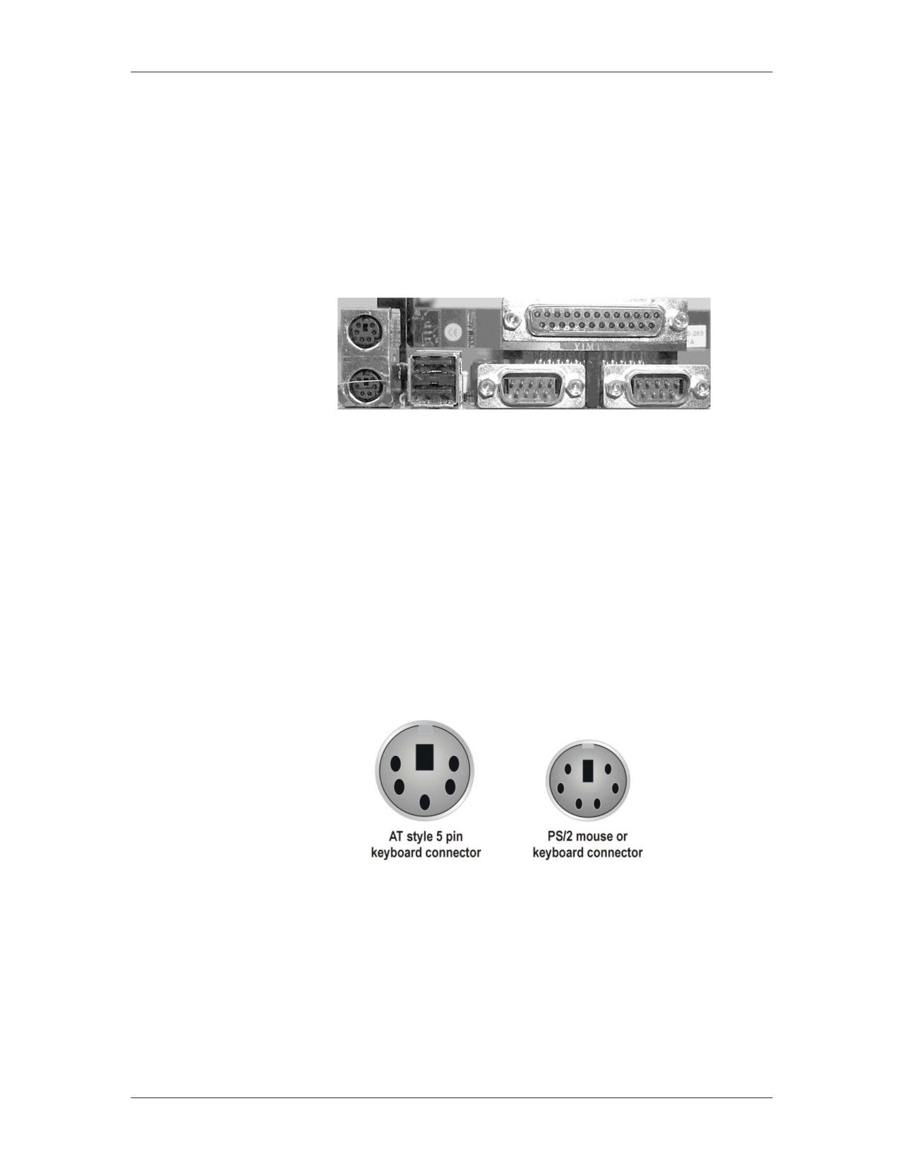
Computer Ports
Mouse and
The characteristics of the mouse and keyboard ports are:
Keyboard Ports
A PS/2 mouse and the keyboard use a barrel shaped 6-pin mini
port
The two ports look exactly alike unless they are color coded or
labeled
A mouse could require a 9-pin serial or USB port
Older keyboards connect using a 5-pin barrel-shaped connector
that is slightly larger than a PS/2 port. Connectors are found on
AT or older motherboards.
PS2 Mouse or Keyboard Port
01/09
For Official Use Only - Law Enforcement Sensitive
E-13
Network Intrusion Responder Program
Appendix E
Input/Output Ports, continued
Serial Ports (Com A serial port sends only one bit of data at a time over one wire, and
1 & Com 2)
is typically used to connect older devices to a computer, such as
modems, touch screens, and proprietary devices. PCs have a
maximum of four serial ports that are referred to as COM 1, COM
2, COM 3, and COM 4. These ports are divided into pairs: COM 1
is paired with COM 3 and COM 2 is paired with COM 4. Each
pair shares the same system resources.
Because they share resources, the ports that comprise a pair cannot
be used at the same time. For example, COM 1 and COM 3 cannot
run at the same time.
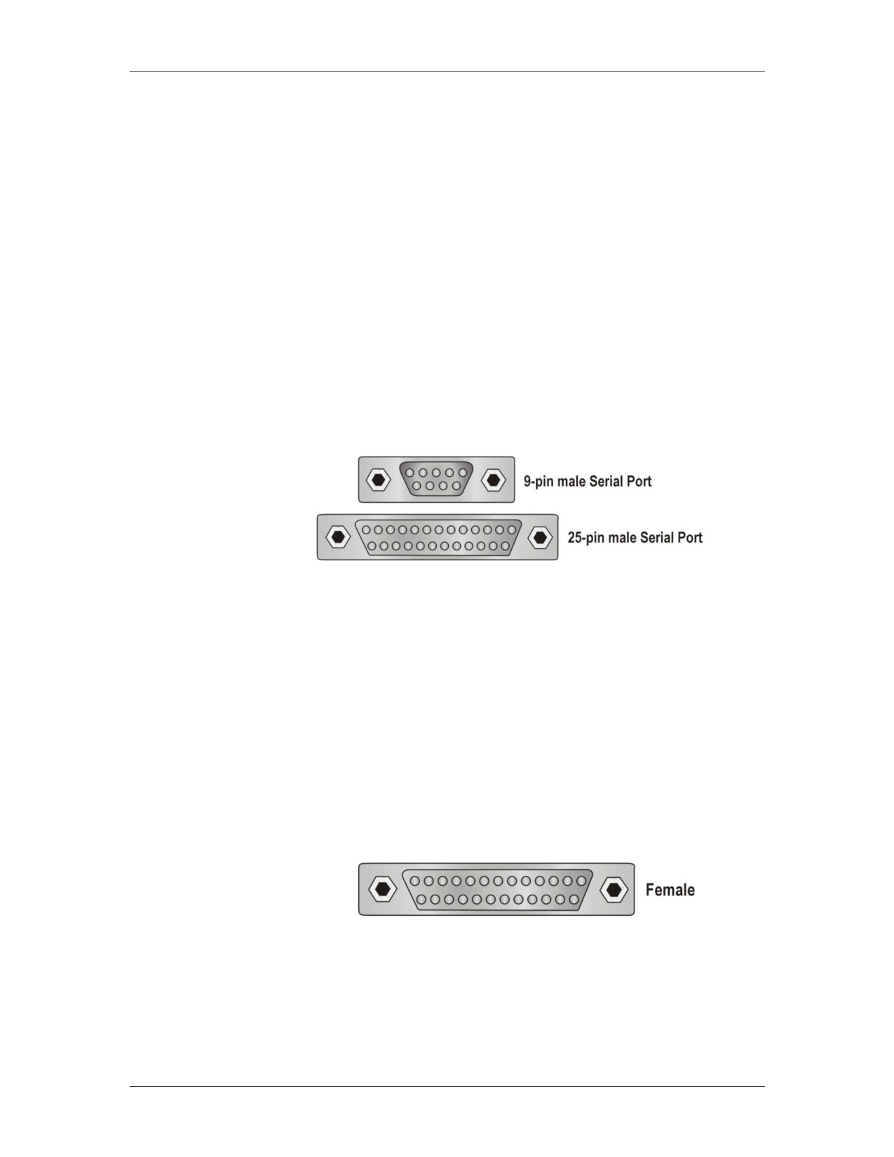
Serial ports have two rows of either 9-pins or 25-pins.
Parallel Port
Most PCs have one parallel port. It is mainly used to connect a
printer although it can be used for certain external drives such as
Zip or Jazz drives. The parallel port is much faster than the serial
port because it can send one byte of data at a time, instead of just a
single bit.
The port is either a 25-pin parallel port or a 36-pin Centronics port.
The SCSI-1 parallel port uses a 50-pin Centronics port. You
should not confuse the different types of parallel ports.
Example of Parallel Port
E-14
For Official Use Only - Law Enforcement Sensitive
01/09
Appendix E
Network Intrusion Responder Program
Input/Output Ports, continued
USB Port
Universal serial bus (USB) port enables many different
components to be connected to the computer sharing the same port
using a connection configuration called daisy chain. The USB port
is a small, flat, rectangular connection that requires a four-wire
cable. The ports are usually found in pairs.
The most important feature of the USB is its ability to hot swap or
change devices without turning off the computer. In theory, 127
devices can be daisy chained.
The transfer rate of USB 1.1 is 12 Megabit/sec (1.5 MB/sec) and
the transfer rate of USB 2.0 is 480 Megabit/sec (60 MB/sec).
The symbol signifying the USB port can be found on the back of
the computer.
USB Symbol
FireWire and
FireWire made by Apple Computers and i.LINK made by Sony are
i.LINK Ports
the manufacturer brand names for IEEE 1394 ports. These ports
are an alternative to a USB port and transfer data at a much higher
speed than USB 1.1, generally 50 MB/sec. They have either 4-pin
or 6-pin connectors with 6-pin port considered the standard. These
ports allow up to 63 devices to be daisy-chained to one connector.
01/09
For Official Use Only - Law Enforcement Sensitive
E-15
Network Intrusion Responder Program
Appendix E
Input/Output Ports, continued
Game Controller Game controller port connects a joystick or other type of game
Port
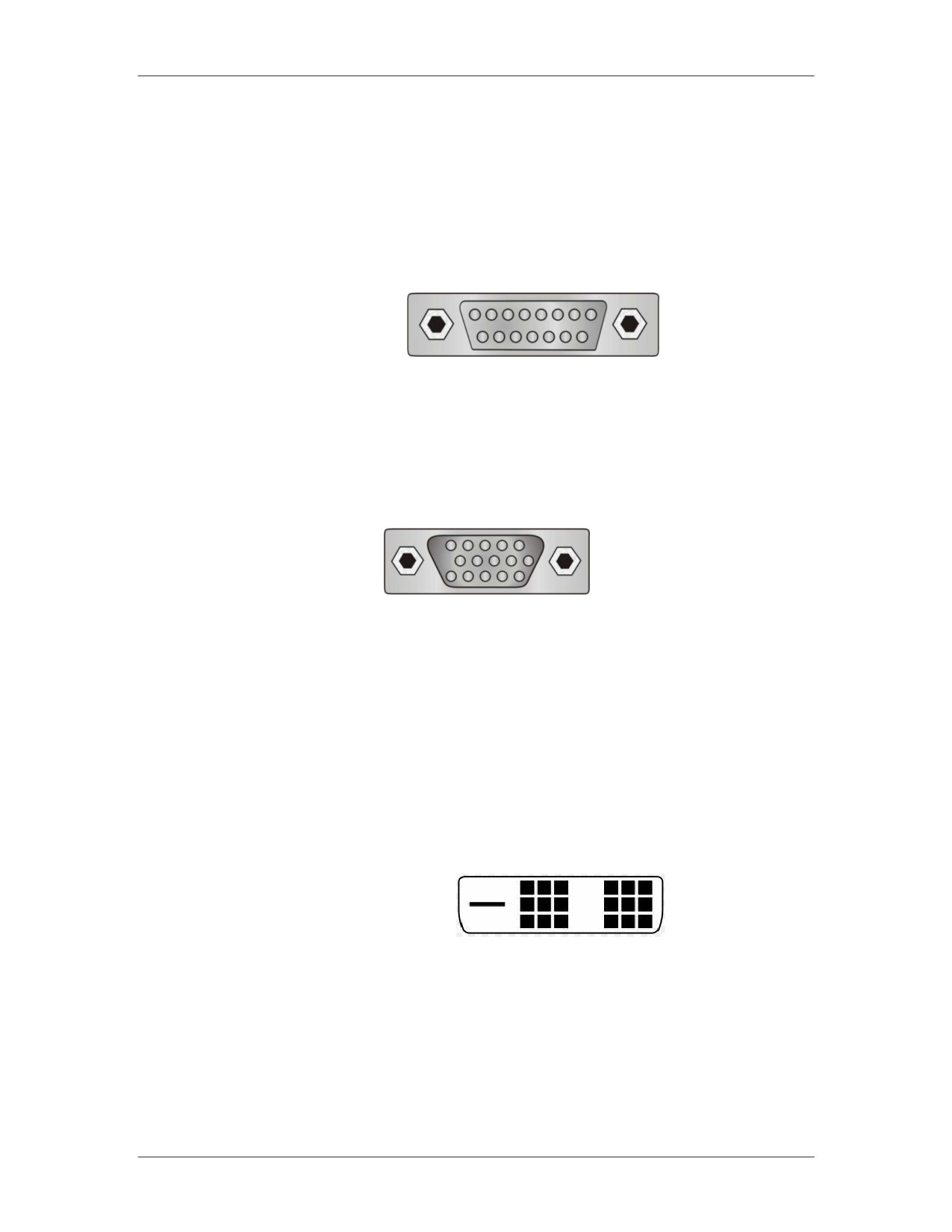
controllers to the PC. The port has 15 pins distributed in two rows.
Game Controller Port
VGA Video
One of the most common video connector ports is the VGA, which
Display Ports
transmits an analog video signal. It has 15 pins distributed in three
rows, forming an arrow that points in one direction.
VGA Video Port
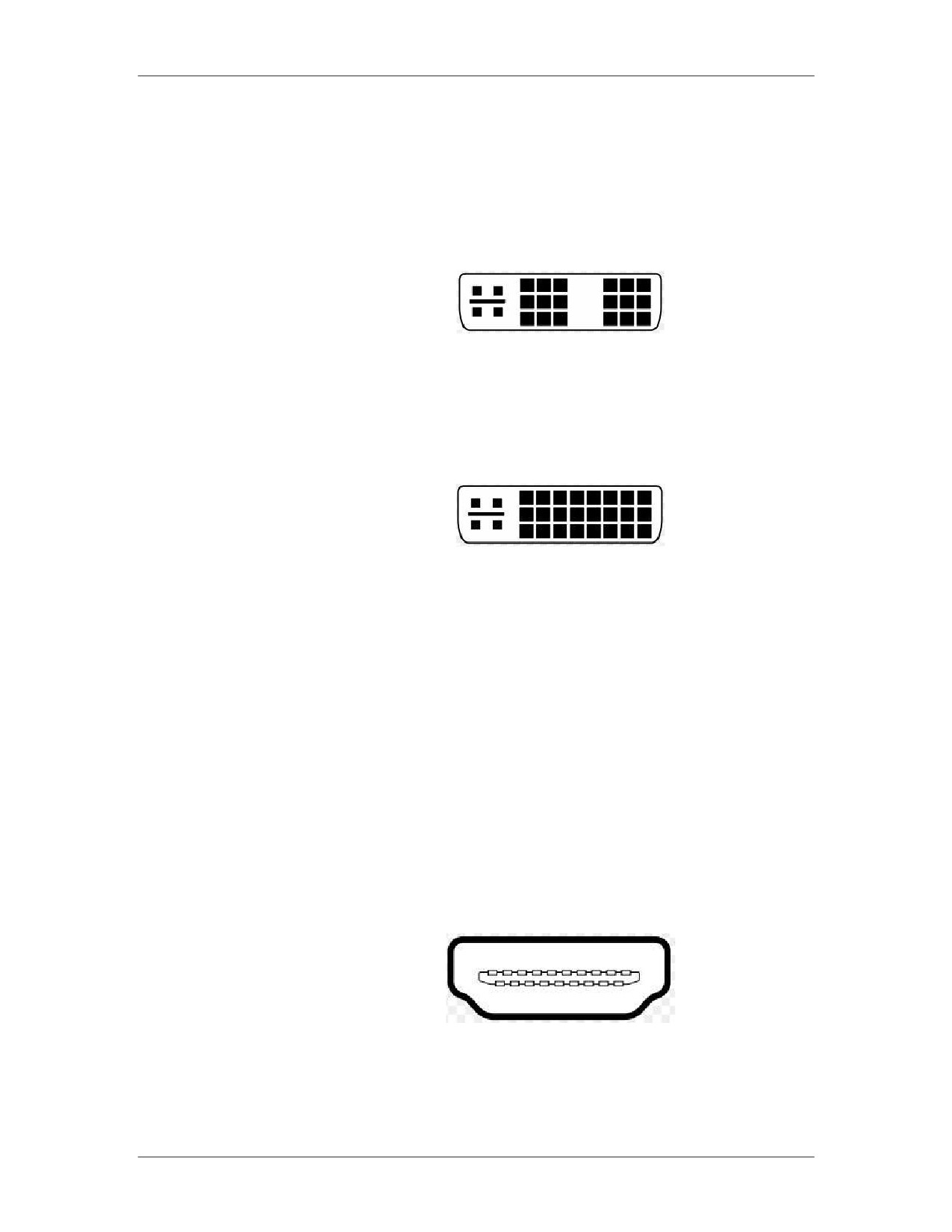
DVI Video Display Evolving from the current VGA standard is DVI, or Digital Visual
Ports
Interface. Unlike VGA‟s analog signal, DVI provides a pure
digital signal for higher quality displays. However, DVI has been
released in a number of different formats, few of which are cross-
compatible.
DVI-D: This format is true digital video. The connection is used
from digital video cards to a digital display. This produces higher
quality output since the signal isn‟t being converted to another
format.
E-16
For Official Use Only - Law Enforcement Sensitive
01/09
Appendix E
Network Intrusion Responder Program
Input/Output Ports, continued
DVI Video Display DVI-I: These cables can be used to carry either digital or analog
Ports, continued
VGA signals. A device with a female DVI-I connector can accept
DVI-D cables along with DVI-I cables.
Along with the different DVI connectors, each is also available as
either Single-Link or Dual-Link. Single-link is the most common
form, but larger displays, such as 30” LCD monitors, require Dual-
Link. Shown below is an example of a DVI-I Dual-Link
connector.
HDMI
High Definition Multimedia Interface (HDMI) is an interface used
to transmit video, audio, and/or device controlling signals. HDMI
supports 1080p high-definition signals and up to 8 channels of
uncompressed audio. The 8 audio channels allow for the use of 7.1
surround sound.
HDMI uses transition minimized differential signaling (TDMS) to
encode the signal to help protect it from degradation during
transmission. The source of the signal encodes the digital signal to
minimize the amount of data required to be sent over the cable.
One of the twisted pairs will send the encoded signal and another
pair will send the inverse of the signal. The receiving device will
decode the signal then compare original and inverse streams. The
device will use that comparative information to compensate for
any degradation of signal during transmission.
01/09
For Official Use Only - Law Enforcement Sensitive
E-17
Network Intrusion Responder Program
Appendix E
Input/Output Ports, continued
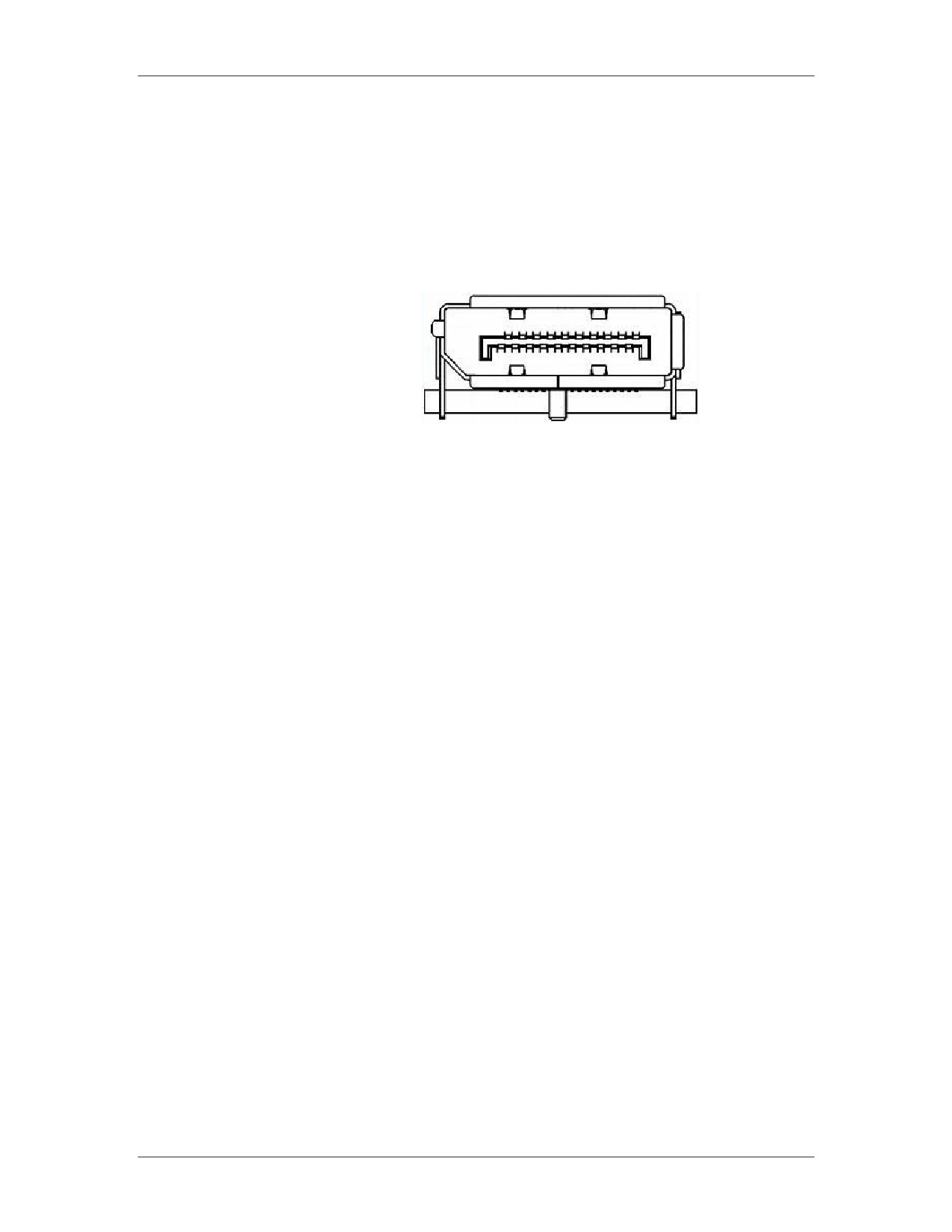
DisplayPort
DisplayPort, supporting 2560x1600 resolutions, is a license and
royalty free competitor of HDMI. A device with the DisplayPort
will be able to connect to any existing DVI, HDMI, VGA, or CRT
monitors.
Sound Ports
Sound cards and sound chips usually have four round 1/8 inch
mini TRS jack ports. These four ports are color-coded and are
defined as line-in, line-out, microphone, and speaker-out. Other
sound ports may be found on the PC including the following ports:
RCA stereo port carries sound to stereo speakers that are not
specifically made for the PC
MIDI port allows the connection of a musical instrument such
as a synthesizer to the PC
Digital audio output
E-18
For Official Use Only - Law Enforcement Sensitive
01/09
Appendix E
Network Intrusion Responder Program
Modems
Modems
Modems handle communication that is transmitted over telephone
lines between computer systems. Most modern modems have fax
capabilities.
PCs are digital devices and the telephone system is an analog
device. The modem is the component that converts (modulates) the
PC‟s digital code to analog so it can be sent over phone cables.
Likewise when receiving information, the modem converts (or
demodulates) analog signals to digital code before transmitting
data to the PC. The transmission mode takes two separate forms:
Asynchronous Mode: This mode of transmission uses
transmission stops, which are nothing more than the periodic
cessation of data transfers. The data is sent in a start and stop
bit fashion.
Synchronous Mode: This mode of transmission is a constant
data stream.
Modems also use two methods to facilitate the transfer of
information:
Data Compression - Speeds data transfer
Error Correction - Allows the modem to detect errors in transit
and either correct these errors or resend the data
Modems have standardized speeds and protocols. Speed is
measured in baud or bits per second and varies depending on the
model. The standard transmission protocol for modern modems is
V.92 protocol that transmits at a speed of 56K.
Types of Modems External Modems
More expensive than internal modems
Include a separate chassis and power supply
Readily identifiable by the LEDs on the front panel
Connect to the serial or USB port. This factor may limit the
modem from reaching its full transmission capabilities.
01/09
For Official Use Only - Law Enforcement Sensitive
E-19
Network Intrusion Responder Program
Appendix E
Modems, continued
Types of Modems, Internal Modems
continued
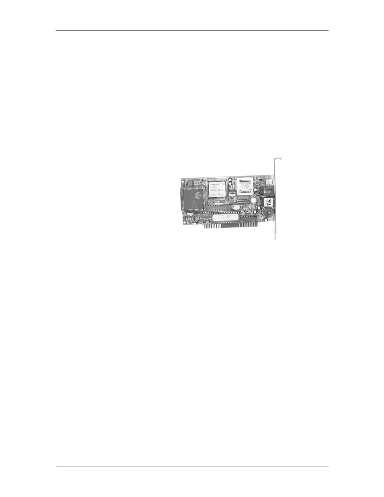
Internal modems are contained on a PCI or ISA card
An internal modem will contain separate communications
circuitry and is not limited by the serial port connection in any
way
Internal modems are less expensive than external modems
Example of Internal Modem
Caution: You should never attempt to connect a real analog
modem to a multi-line or digital connection. Voltage
requirements are different and a connection will
destroy the modem.
Winmodems
Winmodems are internal modems that are configured by device
drivers in an operating system rather than by physical jumpers.
They use the CPU to process data, instead of an onboard chip,
which can degrade system performance. As they require system
drivers to operate, these modems usually only work with Microsoft
Windows.
E-20
For Official Use Only - Law Enforcement Sensitive
01/09
Appendix E
Network Intrusion Responder Program
PC Cards
PC Cards
PC cards, also known as PCMCIA (Personal Computer Memory
Card International Association) cards, are metal-encased
expansion cards about the size of a credit card. These cards, most
often used in laptop computers, add various functions to the
system including:
Fax and modem
Mini-hard drives
Network Interface Card (NIC)
Small Computer System Interface (SCSI) host adapters
Additional RAM and ROM
PC cards are manufactured in the following four types and all
cards have the same dimensions (3.4 inches by 2.1 inches). The
differences are in card thickness and functions. Different card
types require different card ports, although Type I cards can be
read by a Type II reader and Type II cards may be read by a Type
III reader.
Type I is primarily used to add more memory (3.3 mm thick)
Type II is used for modems and NICs (5 mm thick)
Type III is used to add a mini-hard drive (10.5 mm thick)
Type IV is used to add a high-capacity drive. Type IV is not
officially recognized by the PCMCIA and there are no official
standards for implementation.
01/09
For Official Use Only - Law Enforcement Sensitive
E-21
Network Intrusion Responder Program
Appendix E
This page intentionally left blank.
E-22
For Official Use Only - Law Enforcement Sensitive
01/09
Appendix E
Network Intrusion Responder Program
Lesson 2 - BIOS and System Initialization
Introduction
Earlier you learned that the BIOS is part of the motherboard and
its basic function. You will now learn how it interacts with all
parts of the computer and launches the operating system.
Purpose of this
You will understand how the motherboard uses the BIOS to
Lesson
initialize the hardware and start the operating system.
Objectives
After successfully completing this lesson, you will be able to:
Define the role of the BIOS
Discuss what POST codes are
Explain BIOS and the concept of Plug and Play
Explain how a system boots
In this Lesson
The following table shows the contents of this lesson.
Topic
See Page
Motherboard Components
E-24
BIOS Information
E-27
The Boot Process
E-30
The Master Boot Record
E-32
01/09
For Official Use Only - Law Enforcement Sensitive
E-23
Network Intrusion Responder Program
Appendix E
Motherboard Components
Motherboard
The motherboard basic input/output system (BIOS), also called the
BIOS
system BIOS, is considered to be the heart of the computer
because it controls communications between computer hardware
and the operating system. The system BIOS is also referred to as
ROM BIOS because the code is contained in a non-volatile, read-
only memory (ROM) chip.
The system BIOS contains software called firmware. Firmware
provides the basic input/output instructions to boot the computer
and handles several important functions including identifying
hardware currently installed in the PC, determining which device
will boot the PC, and installing basic drivers for keyboard, video,
and disk drives prior to the operating system loading.
CMOS
The CMOS chip, or complementary metal-oxide-semiconductor,
refers to a particular non-volatile memory located on all computer
motherboards that is used to store information from the BIOS.
While modern computers don‟t use a technical CMOS chip
anymore, the term is still used to refer to any memory on the
motherboard used to store motherboard settings. The CMOS is
used to store all values that are configured within the system BIOS
including: hard drive geometries, date and time, and startup
settings.
To maintain the storage of information, even while the machine is
powered off, many CMOS chips are powered by an external
battery. In older machines a typical 9-volt battery is common, but
in modern computers a lithium watch battery has become the new
standard. Such batteries tend to last for up to 10 years.
Functions of
The four major functions of BIOS are:
Motherboard
BIOS
Function 1: Contains and executes the POST
Function 2: Contains the CMOS setup program
Function 3: Executes the bootstrap loader
Function 4: Contains and runs the initial boot device drivers
E-24
For Official Use Only - Law Enforcement Sensitive
01/09
Appendix E
Network Intrusion Responder Program
Motherboard Components, continued
Functions of the
Function 1: Contains and executes the power-on-self-test (POST.)
Motherboard
This is a generalized, hard-coded diagnostic utility that examines
BIOS, continued
crucial components of the system prior to the boot procedure. This
program tests the RAM, video card, keyboard, and disk drives. If
POST finds a fatal error that prevents the system from booting,
POST sends the following alerts:
A series of audio codes or beeps prior to the initialization of
video.
On-screen text messages after initialization of video.
Numeric codes sent to an internal I/O port address. These
codes can only be read by a special PCI or ISA card.
When you encounter these warnings, you can either continue to
boot, if possible, or enter the setup to reconfigure the system and
resolve the error. In addition, you can view the codes on the BIOS
manufacturer‟s Web site.
System BIOS maintains information about all the legacy and Plug
and Play devices that are discovered via POST.
Function 2: Contains the CMOS setup program. When a computer
boots, you can generally find instructions on-screen such as “Press
F1 for Setup.” Setup is a program that is run by the motherboard
BIOS and the data generated by Setup are stored in a separate chip
called CMOS. CMOS stores data such as date and time, which
device is used to boot the PC, and the ability to enable or disable
many of the motherboard functions.
Function 3: Executes the bootstrap loader. This is a code that
queries CMOS to determine the boot device, locates the Master
Boot Record for that device, locates the operating system, boots
the system, and then gives control of the computer to the OS. In
short, this function performs a quick check of the computer system
to ensure that it is ready to accept the operating system.
01/09
For Official Use Only - Law Enforcement Sensitive
E-25
Network Intrusion Responder Program
Appendix E
Motherboard Components, continued
Functions of
Function 4: Contains and runs the initial device drivers needed to
Motherboard
boot the system. A device driver is a small piece of software code
BIOS, continued
that allows the operating system to communicate with a physical
device. The device drivers loaded by the system BIOS are very
basic drivers for keyboard, video, and disk drives. In fact, the
system BIOS contains a table of data for several types of disk
drives.
The BIOS interrogates the drive and uses the information in the
table to identify the drive and to facilitate access to the drive. If the
settings are not found through this identification process, the drive
configuration settings can be entered manually through the Setup
program.
E-26
For Official Use Only - Law Enforcement Sensitive
01/09
Appendix E
Network Intrusion Responder Program
BIOS Information
BIOS Setup
All X86 motherboard architecture personal computers have BIOS.
The BIOS contains a program called Setup that allows users to
configure low-level system settings of the computer. Typing a
certain combination of keystrokes during the boot process accesses
Setup. These keystrokes differ among the different BIOS
manufacturers. When initial program load (IPL) ends
(immediately before the computer loads the OS), the BIOS will
generally pause for one to two seconds and display the keystroke
combination that initializes Setup.
For most computers, you press the Delete key to access Setup.
Others (especially proprietary systems such as Compaq and
Packard-Bell) may require pressing these keys: F1, F2, F10,
CTRL-A, or CTRL-S. If you cannot determine the keystroke to
activate Setup, refer to written documentation prepared by the
BIOS manufacturer. BIOS settings configured by Setup are
actually stored in the CMOS chip as standard practice for most
systems.
BIOS Menu
Setup usually contains a menu system that allows easy access to
System
system settings. Data and options are divided into categories of
relevance. While searching for data, it may be necessary to search
through the various menus. However, be very careful of what
keystrokes you use. Keystrokes to change settings and navigate the
menu differ, depending on the manufacturer. For example, the
arrow keys that may navigate in one Setup program may actually
change configuration values in another.
When exiting the setup program, be sure to select the exit option
that will not save any changes, so as to not overwrite the original
settings.
01/09
For Official Use Only - Law Enforcement Sensitive
E-27
Network Intrusion Responder Program
Appendix E
BIOS Information, continued
In Cases of
A password protected BIOS is a security measure intended to
Password
prevent trespassers from viewing vital details of the computer‟s
Protection
configuration. Some motherboards have a built-in backdoor
password that can be used to gain access to the BIOS at any time.
However, for many motherboards, the only way to quickly
circumvent this security is to completely erase the CMOS (which,
in turn, erases the suspect‟s BIOS settings.) Here are common
ways to erase the CMOS:
1. Locate and change the CMOS “clear jumper” on the MB
2. Remove and replace the CMOS battery
Note: If you are forced to erase the BIOS settings, record this in
your notes. Skip the steps of recording BIOS information.
Vital Information
To create a case profile, you need to gather as much pertinent
to Record Time
information as possible from the suspect‟s computer. Primary data
and Date
includes the date and time of the computer. Document this data
and also note any discrepancies between the values on the
computer and the actual time and date.
Boot Order
This sets the order in which bootable devices are scanned by the
BIOS. This may be changed in Setup very easily, and the order is
generally designated by “First,” “Second,” or “Third.”
Investigators should document the original order as set by the
suspect.
If the “First” boot device is the network card, this may be an
indication that the alleged crimes did not occur on this hard drive,
but on a network server. Record this fact in your notes.
E-28
For Official Use Only - Law Enforcement Sensitive
01/09
Appendix E
Network Intrusion Responder Program
BIOS Information, continued
Hard Drive
You need to record the configuration of the hard drives and
Information
storage drives in the BIOS. Most computers have the capability to
control four IDE devices at once or two per connector. Document
settings for each device. Possible settings are “Auto-Detect,”
“User-Defined,” or “None.”
If set for “User-Defined,” record all the numerical settings that are
entered, including the Cylinders, Heads, Precomp, and whether or
not LBA is in use. Cross-reference this information with that
which was obtained during the internal examination (e.g.,
information from hard drive labels, etc.) and note any
discrepancies.
Note: This information will be important if you want to restore the
hard drive image.
01/09
For Official Use Only - Law Enforcement Sensitive
E-29
Network Intrusion Responder Program
Appendix E
The Boot Process
Boot Process
All computers are designed to start in a predictable way from the
Overview
moment you press the Power On button until the moment the
operating system loads. The list below outlines the steps.
Boot Process
Activity
Description
1. Power on
When you press the Power On
button and the power supply
reaches working voltage the
Power_Good line is set to true on
the microprocessor.
2. CPU looks at ROM for
When CPU receives power good
basic instructions (BIOS)
signal it starts to load the program
at memory location 0000h, which
is the start of the BIOS.
3. System BIOS loads
4. BIOS initiates POST
POST = Power On Self Test
5. POST checks RAM and
Depending on the manufacturer,
then Video.
POST error codes vary.
If either of these have a
problem, the result are various
The following web site has many
beep codes from the speaker.
of the industry error codes
outlined for you.
From this point forward,
errors are reported with text
messages displayed on the
monitor.
6. When RAM and Video
You will begin to see text on the
pass the POST test, a single
screen. The rapid numbers
beep occurs. The single beep
flashing indicate an in-depth
exists simply to indicate that
RAM check. The screen will
the diagnostic speaker is
indicate the BIOS manufacturer
working. A malfunctioning
and version number.
speaker will prevent audible
beep codes.
E-30
For Official Use Only - Law Enforcement Sensitive
01/09
Appendix E
Network Intrusion Responder Program
The Boot Process, continued
Boot Process Overview, continued
Boot Process, continued
Activity
Description
7. POST then checks
If an error occurs, a text message
keyboard.
generally displays the on-screen
8. The BIOS checks memory
If this is a warm start then the
location 0472h for the value
BIOS shortens the check and load
1234h which indicates a
process to only those things
„warm start‟, or that the reset
necessary to start the system,
button was pressed.
versus a full diagnostic check.
9. CMOS data is compared
If there is a problem with the
against new current
CMOS battery, you will get a text
configuration data. Drives
message.
spin, lights flash, and sounds
are heard as circuits are tested
and prepared for system start-
up.
10. Finding no major
The boot loader starts and the
hardware errors, BIOS turns
search for the Master Boot
the process over to the
Record begins.
operating system boot loader
on the default boot device.
11. The boot loader learns the
boot sequence from (e.g. A:
C: CD-ROM, etc.) and looks
for the Master Boot Record
on that device.
For hard disks, the boot loader
looks for a partition table. The
partition table will have a
pointer to the MBR on the
primary, active partition
12. The MBR contains the
first file needed to start the
operating system (IO.SYS in
Windows 9x, boot.ini in NT).
13. The whole process is
turned over to the OS and you
see splash screens, etc.
01/09
For Official Use Only - Law Enforcement Sensitive
E-31
Network Intrusion Responder Program
Appendix E
The Master Boot Record
The MBR Defined Since the early days of the disk operating system on personal
computers the last thing the boot loader does is search for the
Master Boot Record (MBR) for the operating system loaded on the
computer. Originally this was found at cylinder 0, head 0, sector 1
of the default boot drive.
Historically this was usually the floppy disk drive.
Today just about any storage device can be configured in the BIOS
as the default boot device, including USB drives, CD‟s, DVD‟s
and even booting from the network interface.
E-32
For Official Use Only - Law Enforcement Sensitive
01/09