ORGANIZATIONAL MAINTENANCE MANUAL WITH REPAIR PARTS LIST FOR RIFLE, 7.62 MM, AK-47 (2009) - page 2
TM 8370-50007-IN/2
0013 00
NOTE
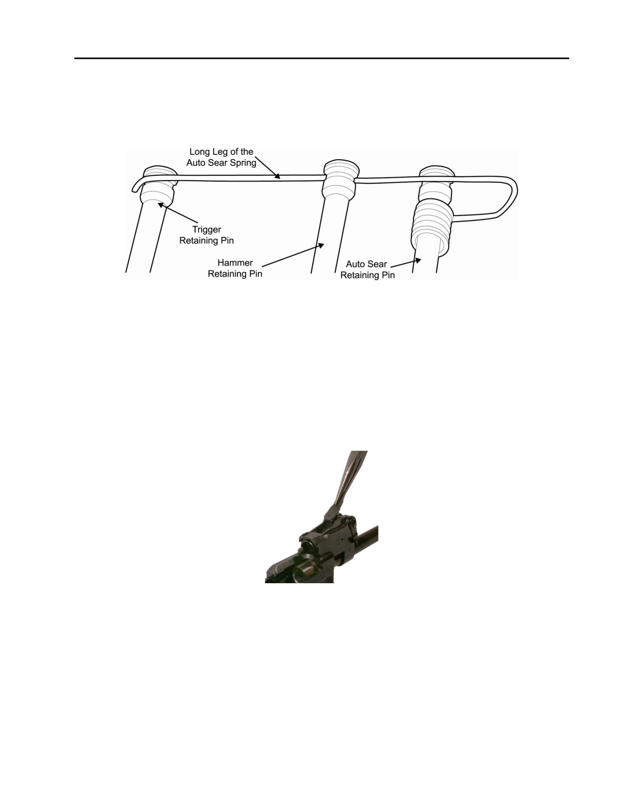
Ensure that the long leg of the auto sear spring is properly installed. Refer to
Figure 45. The long leg of the auto sear spring must be properly set into the
grooves in the heads of the three retaining pins in the receiver in order to
retain the pins in the receiver.
Figure 45. Proper Installation of the Long Leg of the Auto Sear Spring.
4. Rear Sight.
NOTE
When installing the rear sight leaf spring, restaking it into the rear sight base
may be necessary.
a. Use needle-nosed pliers to install the leaf spring into the rear sight base, ensuring that the dimple on
the leaf spring corresponds to the hole in the rear sight base and that the wide, rear end is fully seated
in the cut out in the top of the rear sight base. Refer to Figure 46.
Figure 46. Installing the Rear Sight Leaf Spring.
0013 00-23
TM 8370-50007-IN/2
0013 00
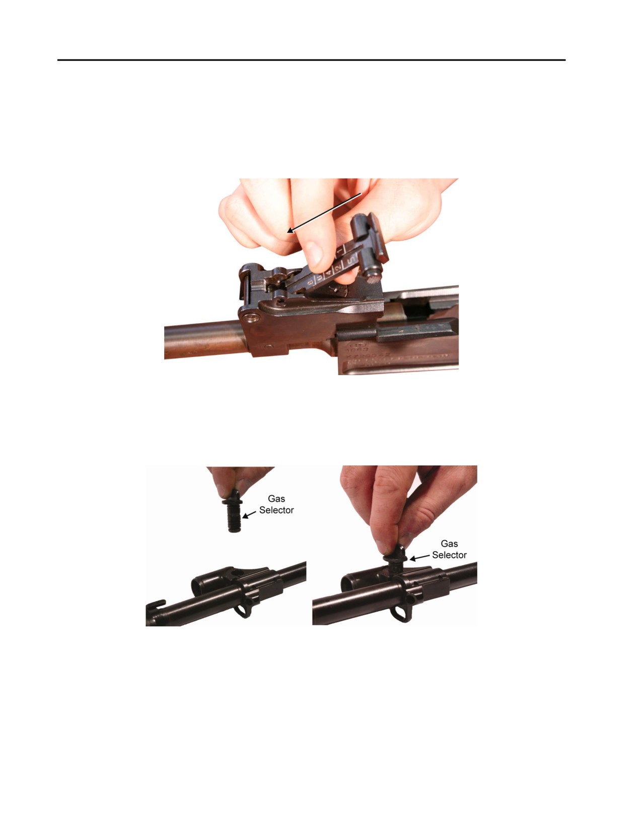
NOTE
Ensure the numbers on the rear sight assembly are facing upwards when
installing the rear sight assembly.
b. Holding the rear sight assembly at a 45 degree angle, push the studs on the bottom of the rear sight
assembly down and forward into the grooves on the rear sight base until they are seated in the holes in
the rear sight base. It may be necessary to use a dead blow mallet. Refer to Figure 47.
Figure 47. Installing the Rear Sight Assembly.
5. Gas Block.
a. Install the gas selector from the right side of the gas block. Refer to Figure 48.
Figure 48. Installing the Gas Selector.
0013 00-24
TM 8370-50007-IN/2
0013 00
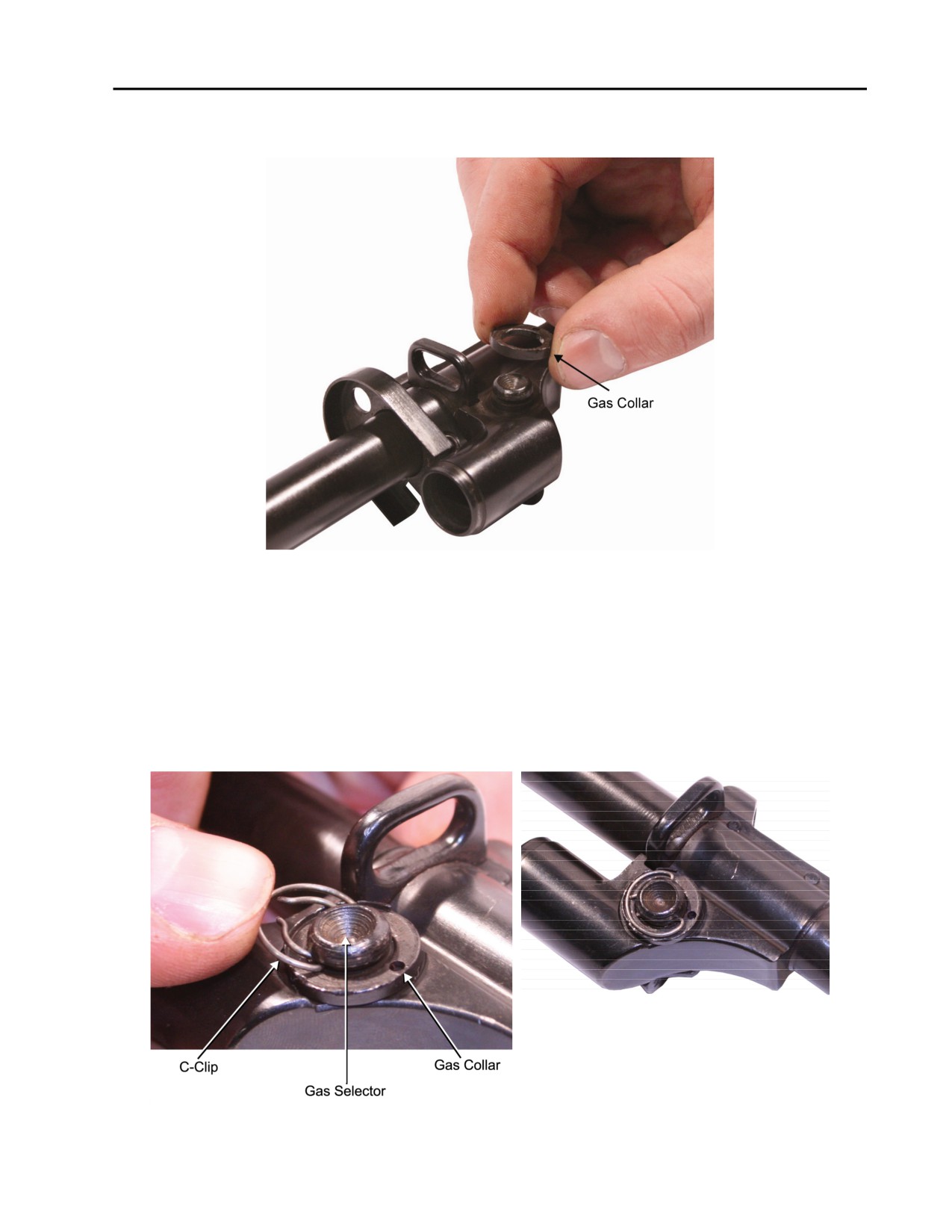
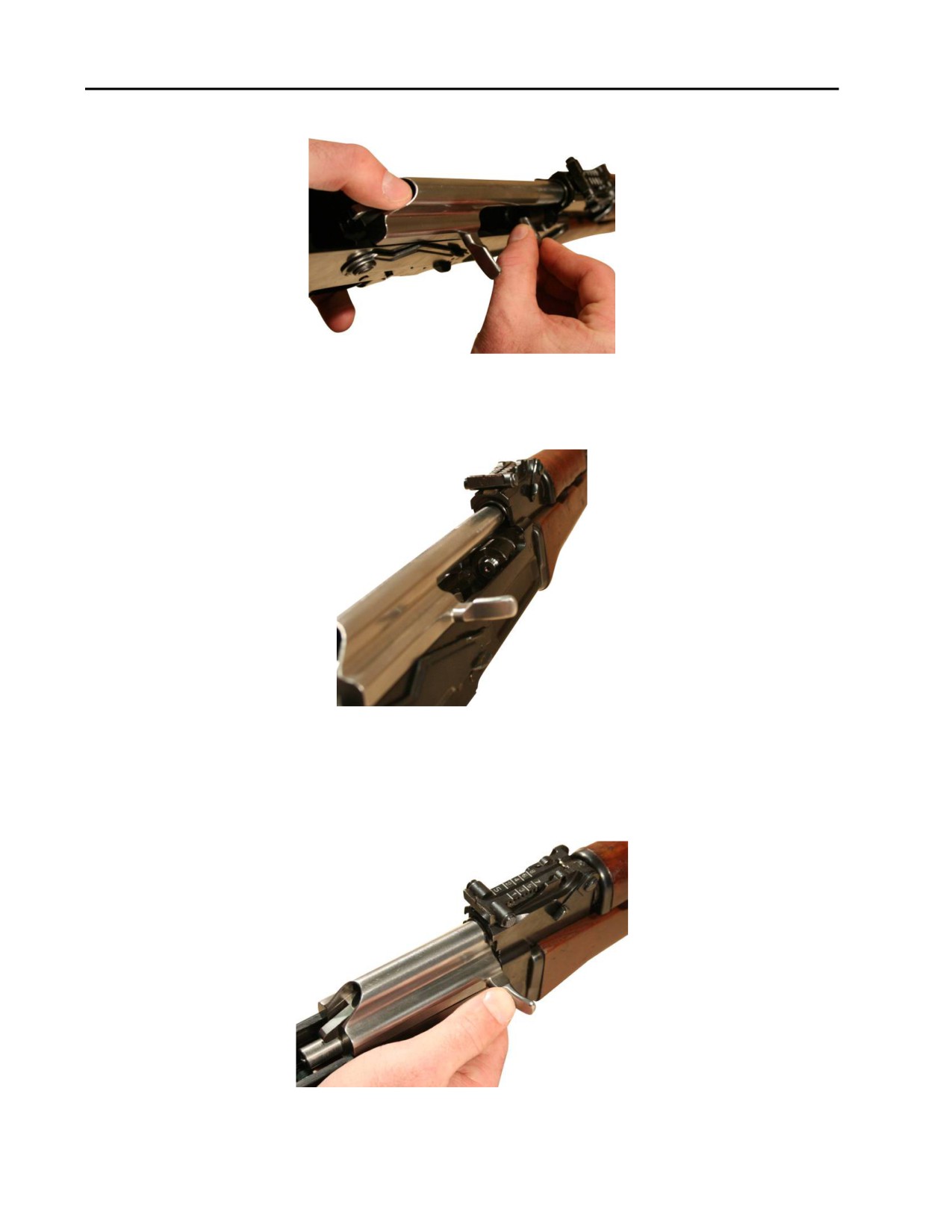
b. Install the gas collar on the left side of the gas block over the end of the gas selector. Refer to
Figure 49.
Figure 49. Installing the Gas Collar.
CAUTION
The C-clip can break and deform during installation. If the C-clip becomes
bent or deformed, it should be replaced. Ensure that the open end of the
C-clip is facing towards the muzzle.
c. Install the C-clip on the left side of the gas block by pushing the open end of the C-clip against the
end of the gas selector until it is seated around the end of the gas selector. Refer to Figure 50.
Figure 50. Installing the C-Clip and the C-Clip Installed.
0013 00-25
TM 8370-50007-IN/2
0013 00
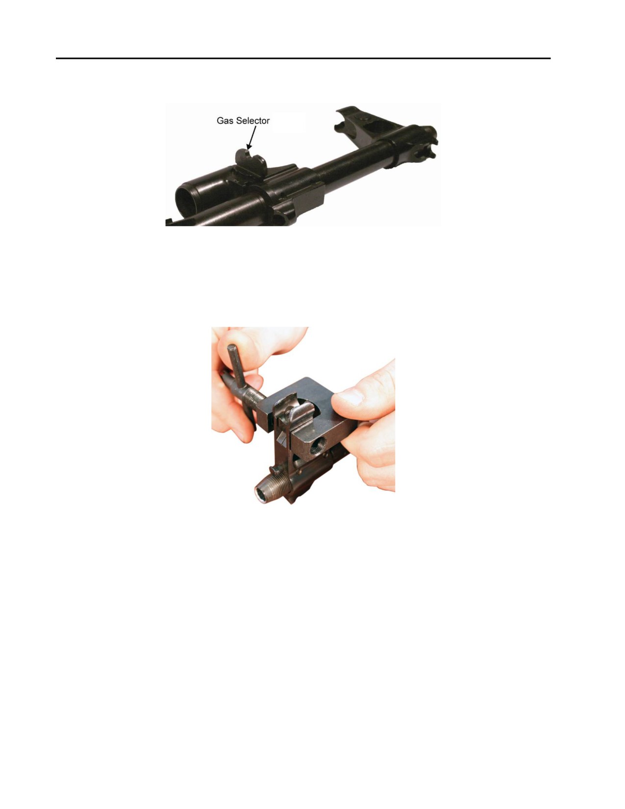
d. Switch the gas selector to the UP position (perpendicular to the barrel), indicating normal use. Refer
to Figure 51.
Figure 51. Gas Selector in the UP Position.
6.
Muzzle and Front Sight.
a. Using the front sight adjustment tool, install the windage drum into the front sight base. Refer to
Figure 52.
Figure 52. Installing the Windage Drum.
0013 00-26
TM 8370-50007-IN/2
0013 00
NOTE
The M249 front sight tool can also be used for working on the front sight.
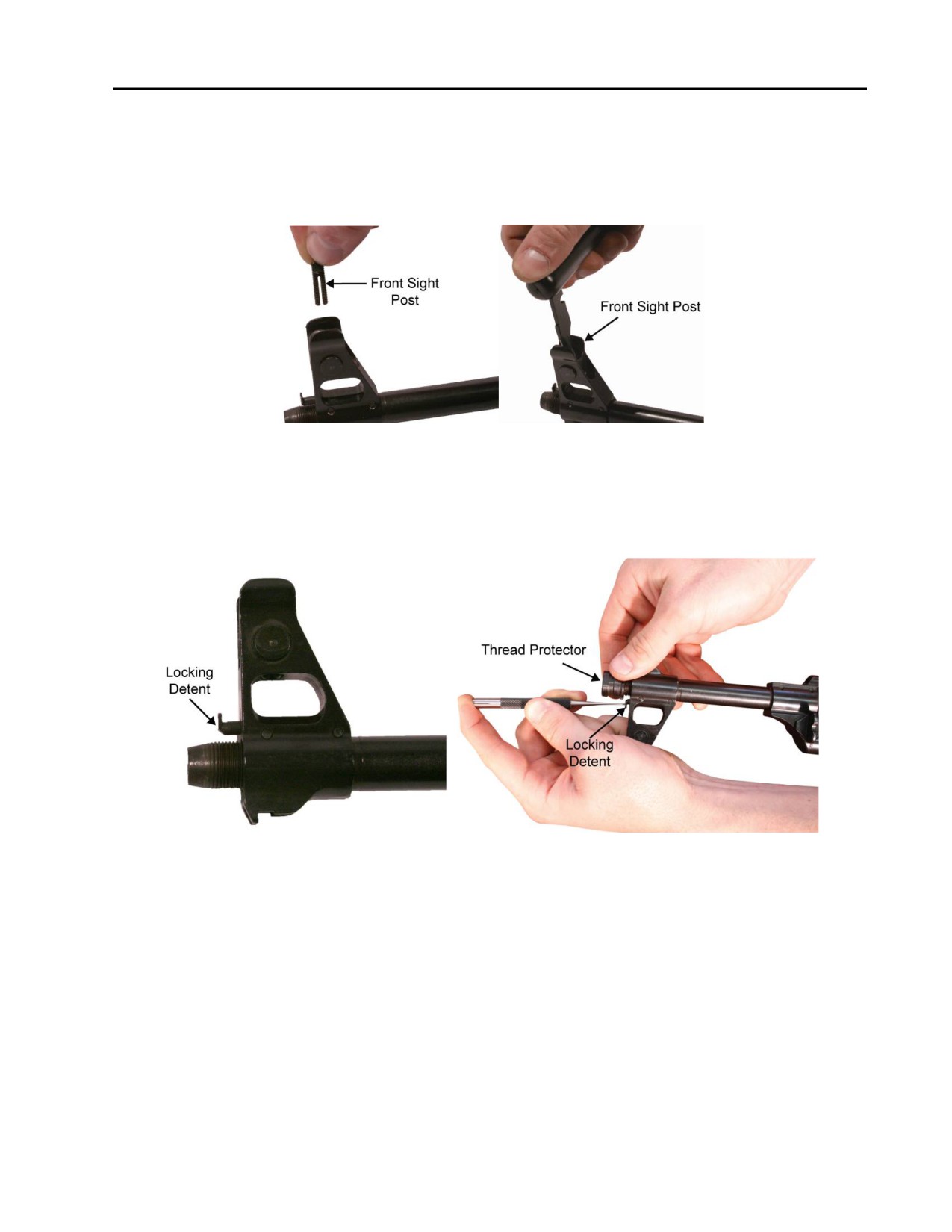
b. Using the front sight adjustment tool or the AK-47 combination tool, install the front sight post. Refer
to Figure 50.
Figure 53. Installing the Front Sight Post.
c. While using a punch to hold down the locking detent, turning the thread protector until it is seated
tightly on the muzzle. Ensure that the locking detent is seated in one of the notches in the thread
protector. Refer to Figure 54.
Figure 54. Installing the Thread Protector on the Muzzle.
END OF WORK PACKAGE
0013 00-27/28 blank

INTENTIONALLY BLANK
TM 8370-50007-IN/2
0014 00
REAR SIGHT ASSEMBLY
THIS WORK PACKAGE DESCRIBES
Disassembly, Cleaning, Inspection and Repair, Lubrication, and Reassembly.
INITIAL SETUP
Maintenance Level
References
Organizational
WP 0009 00
WP 0013 00
Tools and Special Tools
WP 0025 00
E7900 tool kit
Equipment Conditions
Rear sight assembly removed (WP 0013 00)
DISASSEMBLY
WARNING
The elevation slide assembly is under spring tension. Use care when working
on spring-loaded parts.
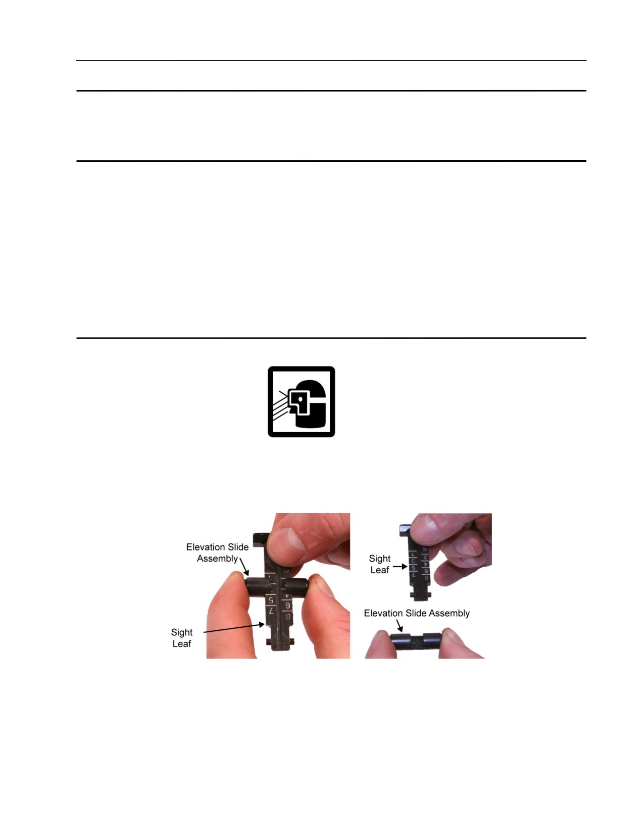
1. Depress the elevation slide assembly and remove it from the sight leaf. Refer to Figure 1.
Figure 1. Depressing the Elevation Slide Assembly and Removing it from the Sight Leaf.
0014 00-1
TM 8370-50007-IN/2
0014 00
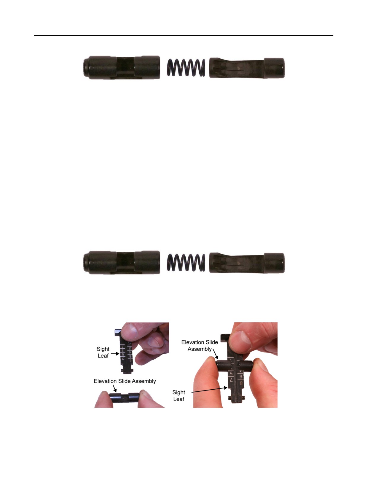
2. Disassemble the slide, spring, and catch. Refer to Figure 2.
Figure 2. Disassembled Slide, Slide Spring, and Slide Catch.
CLEANING
Clean and remove all carbon deposits from the weapon. Refer to TM 8370-50007-OR/1.
INSPECTION AND REPAIR
1. Inspect the sight leaf for cracks, deformities, and breaks. Replace the sight leaf if damaged.
2. Inspect the slide spring for spring tension, bends, or breaks. Replace the slide spring if damaged.
3. Inspect the slide and slide catch for cracks and burrs. Remove the burrs. Replace the slide or catch if
damaged.
LUBRICATION
For all lubrication requirements refer to TM 8370-50007-OR/1.
REASSEMBLY
1. Assemble the slide, slide spring, and slide catch. Refer to Figure 3.
Figure 3. The Slide, Slide Spring, and Slide Catch.
2. Depress the elevation slide assembly and install it onto the sight leaf. Ensure the teeth on the elevation
slide assembly mate with the teeth on the sight leaf. Refer to Figure 4.
Figure 4. Depressing and Installing the Elevation Slide Assembly onto the Sight Leaf.
END OF WORK PACKAGE
0014 00-2
TM 8370-50007-IN/2
0015 00
FIXED BUTTSTOCK ASSEMBLY
THIS WORK PACKAGE DESCRIBES
Disassembly, Cleaning, Inspection and Repair, Lubrication, and Reassembly.
INITIAL SETUP
Maintenance Level
References
Organizational
TM 8370-50007-OR/1
WP 0013 00
WP 0025 00
Tools and Special Tools
Equipment Conditions
E7900 tool kit
Fixed buttstock removed (WP 0013 00)
FIXED BUTTSTOCK ASSEMBLY
WARNING
The buttplate and trapdoor are under spring tension. Use care when removing
the trap door and buttplate.
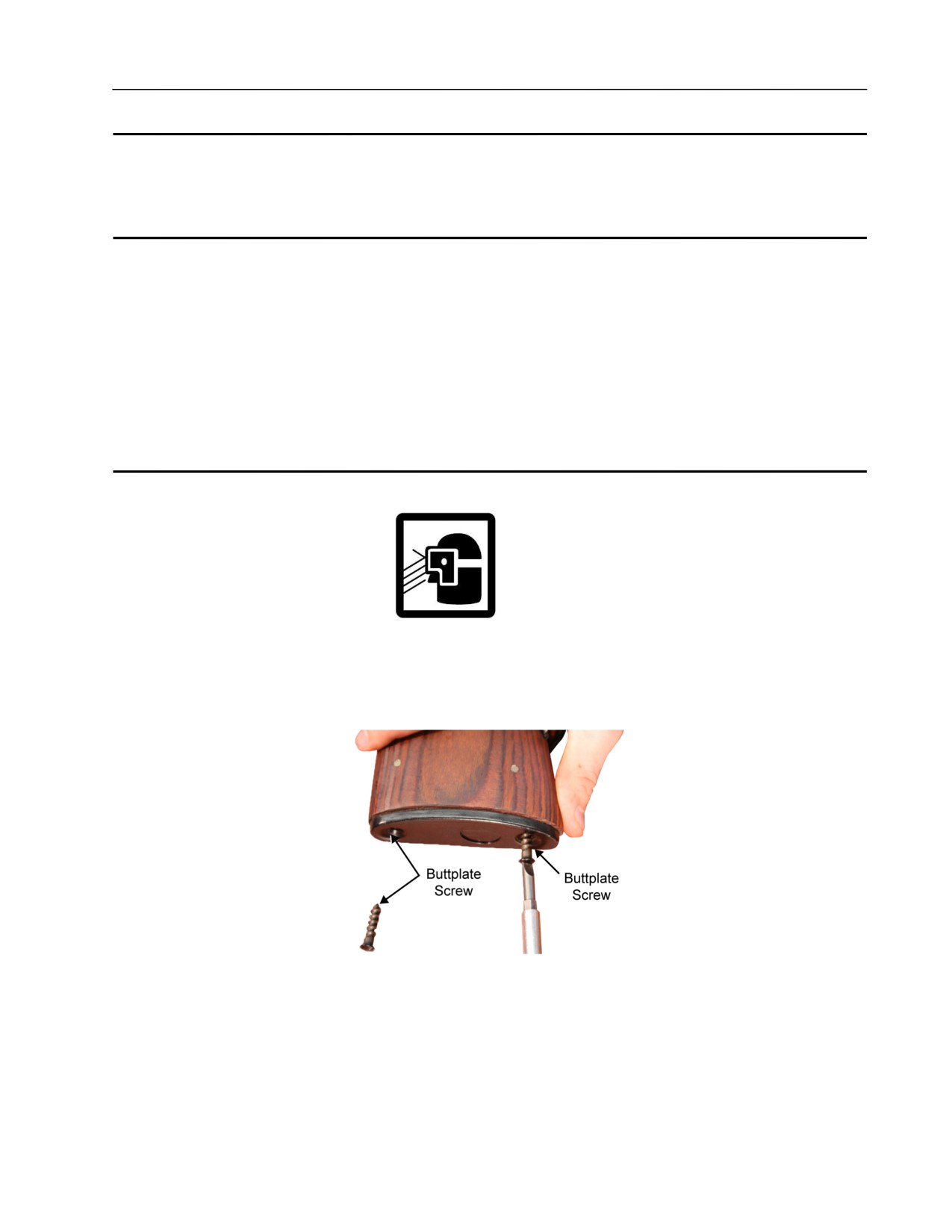
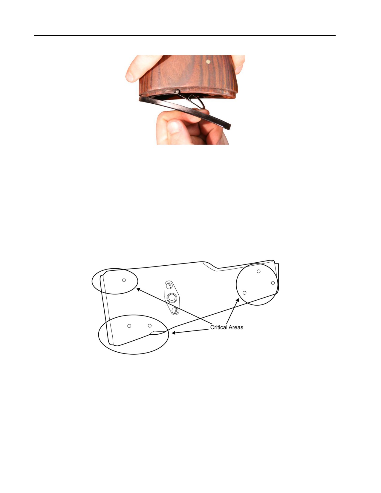
1. Using a flat head screwdriver, remove the two buttplate screws from the buttplate. Refer to Figure 1.
Figure 1. Removing the Buttplate Screws.
0015 00-1
TM 8370-50007-IN/2
0015 00
2. Remove the buttplate, trap door, and buttstock spring from the buttstock. Refer to Figure 2.
Figure 2. Removing the Buttplate and Trap Door.
NOTE
Do not remove the buttstock spring unless replacement is needed.
CLEANING
Clean and remove all carbon deposits from the weapon. Refer to TM 8370-50007-OR/1.
INSPECTION AND REPAIR
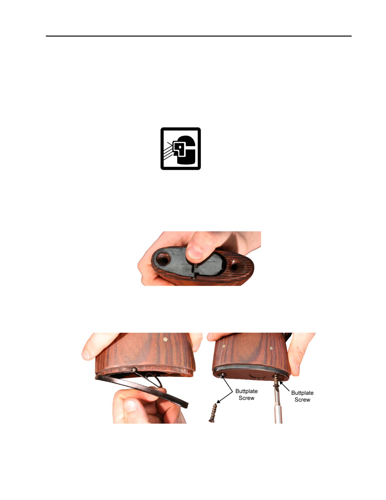
1. Check the fixed buttstock for cracks. Up to three cracks are acceptable. No cracks are acceptable in the
critical areas (near pins and screws). Refer to Figure 3. Replace the buttstock if defective.
Figure 3. Critical Areas of the Buttstock.
2. Check the screws for burrs. Remove the burrs. Replace the screws if damaged.
3. Check the spring for breaks, distortion, and spring tension. Replace the spring if damaged.
4. Check the buttplate and trap door for bends, cracks, and burrs. Remove the burrs. Replace the buttplate
and trap door if damaged.
5. Check the trap door spring for spring tension. Replace the trap door spring if damaged.
0015 00-2
TM 8370-50007-IN/2
0015 00
6. Check the fixed buttstock for front-to-rear movement or looseness between the buttstock and the receiver.
If there is front-to-rear movement or looseness, remove the screw, clean the threads, apply thread locker,
and reinstall the screw or replace it with a new buttstock screw.
LUBRICATION
For all lubrication requirements, refer to TM 8370-50007-OR/1.
REASSEMBLY
1. If removed, insert the buttstock spring, large end first, into the fixed buttstock.
WARNING
The trap door is under spring tension. Use care when installing the trap door
and buttplate.
2. Place the trap door on the end of the fixed buttstock with the folded end facing the buttstock spring.
Ensure that the screw hole in the trap door is aligned with the screw hole in the fixed buttstock. Refer to
Figure 4.
Figure 4. The Trap Door Placed on the Fixed Buttstock.
3. Place the buttplate over the trap door ensuring that the hole in the buttplate is over the folded side of the
trap door. Secure the buttplate with the two buttplate screws. Refer to Figure 5.
Figure 5. Installing the Buttplate and Buttplate Screws.
END OF WORK PACKAGE
0015 00-3/4 blank

INTENTIONALLY BLANK
TM 8370-50007-IN/2
0016 00
REASSEMBLY OF WEAPON
THIS WORK PACKAGE DESCRIBES
Reassembly.
INITIAL SETUP
Maintenance Level
Equipment Conditions
Organizational
Weapon disassembled into major components
(WP 0010 00)
References
TM 8370-50007-OR/1
WP 0010 00
WP 0017 00
WARNINGS
Use care when installing and unloading spring-loaded parts. DO NOT
interchange bolt assemblies from one weapon to another. DO NOT keep live
ammunition in the work area. Failure to follow these warnings may cause
injury or death to personnel.
0016 00-1
TM 8370-50007-IN/2
0016 00
REASSEMBLY
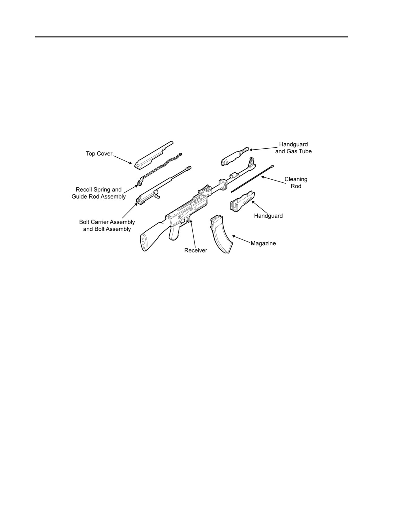
Refer to Figure 1.
1. Refer to TM 8370-50007-OR/1.
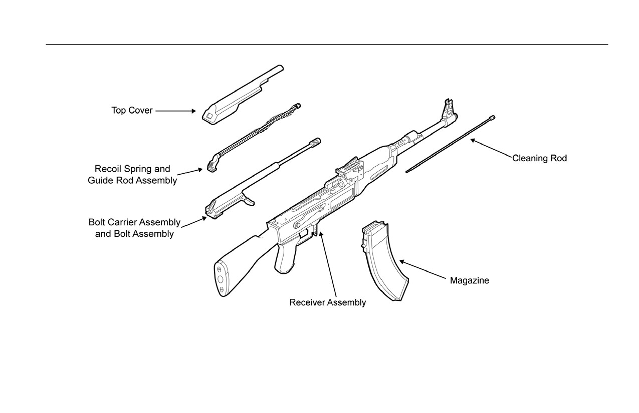
2. Install the handguards and gas tube onto the barrel. Install the cleaning rod under the barrel.
3. Install the bolt carrier assembly and bolt assembly and the spring and guide rod assembly into the
receiver. Install the top cover onto the receiver.
4. Function check the weapon. Refer to WP 0017 00.
Figure 1. Major Components of the AK-47.
END OF WORK PACKAGE
0016 00-2
TM 8370-50007-IN/2
0017 00
FUNCTION CHECK
THIS WORK PACKAGE DESCRIBES
Function Check.
INITIAL SETUP
Maintenance Level
Equipment Conditions
Organizational
Weapon cleared (TM 8370-50007-OR/1)
References
TM 8370-50007-OR/1
WARNING
Ensure that the weapon is clear prior to performing the following function
checks. If the weapon fails any of the following function checks, attempt to
repair it. If the weapon is beyond repair, replace it.
GENERAL
This section contains instructions for checking the functions of the AK-47 rifle.
FUNCTION CHECK
1. Perform the following function checks on assembled weapons only.
2. Remove the magazine, if inserted.
3. Place the selector lever on AUTO. Refer to Figure 1.
Figure 1. Selector Lever on AUTO.
0017 00-1
TM 8370-50007-IN/2
0017 00
4. Pull and hold the charging handle to the rear. Ensure that the chamber is clear. Release the charging
handle.
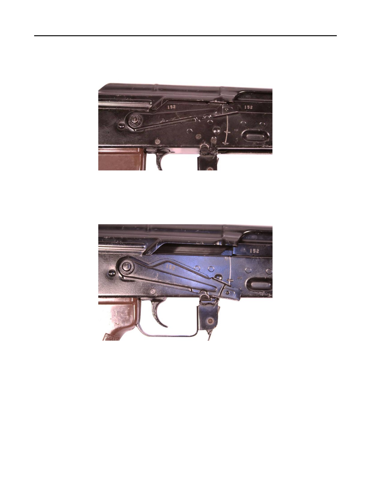
5. Place the selector lever on SAFE. Refer to Figure 2.
Figure 2. Selector Lever on SAFE.
6. Pull the trigger. The hammer should not fall.
7. Place the selector lever on SEMI. Refer to Figure 3.
Figure 3. Selector Lever on SEMI.
8. Pull and hold the trigger to the rear. The hammer should fall.
0017 00-2
TM 8370-50007-IN/2
0017 00
9. While continuing to hold the trigger to the rear, charge the weapon.
10. Slowly release the trigger. An audible “click” should be heard. The hammer should not fall.
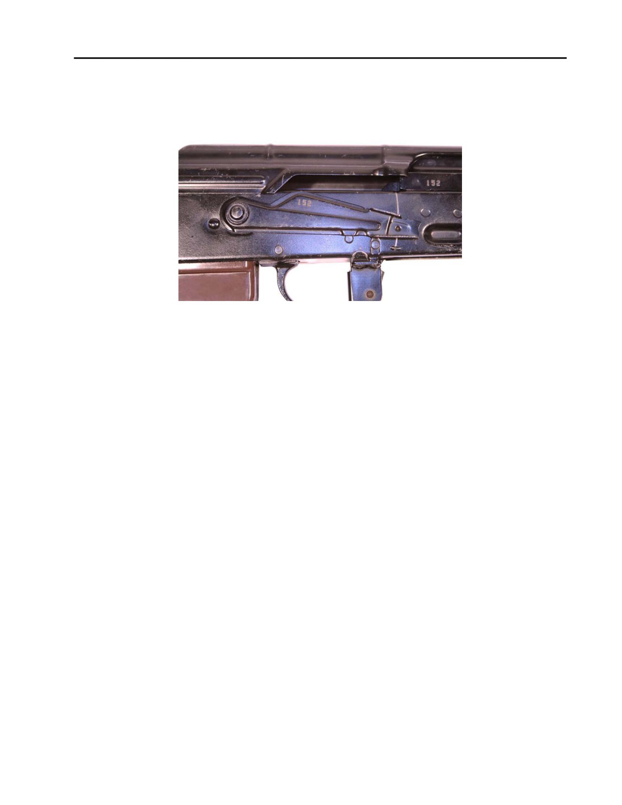
11. Place the selector lever on AUTO. Refer to Figure 4.
Figure 4. Selector Lever on AUTO.
12. Pull and hold the trigger to the rear. The hammer should fall.
13. While continuing to hold the trigger to the rear, charge the weapon and release the trigger. The hammer
should not fall. An audible “click” should not be heard. The hammer should already be in the forward
position and should not fall when the trigger is pulled again. Pull the trigger again. The hammer should
not fall.
14. Repeat steps 12 and 13.
15. Leaving the hammer in the forward position, attempt to place the selector lever on SAFE. The selector
lever SHOULD move to the SAFE position.
16. Place the weapon on SAFE, if it is not already.
END OF WORK PACKAGE
0017 00-3/4 blank

INTENTIONALLY BLANK
TM 8370-50007-IN/2
0018 00
STOWAGE
THIS WORK PACKAGE DESCRIBES
Stowage.
INITIAL SETUP
Maintenance Level
Equipment Conditions
Organizational
Weapon cleared (TM 8370-50007-OR/1)
References
TM 8370-50007-OR/1
WARNING
Before stowing a weapon, be sure to clear the weapon
(TM 8370-50007-OR/1). Inspect the chamber to ensure it is empty and that
no ammunition is in position to be chambered. Failure to follow this warning
may cause injury or death to personnel.
STOWAGE
Prior to stowing the weapon in the arms room, perform the following procedures:
1. Clear weapon.
2. Place selector lever in SEMI position.
3. Pull trigger. Hammer should fall.
4. Place weapon on SAFE.
5. Place weapon on rack.
END OF WORK PACKAGE
0018 00-1/2 blank

INTENTIONALLY BLANK
TM 8370-50007-IN/2
0019 00
PREPARATION FOR STORAGE AND SHIPMENT
THIS WORK PACKAGE DESCRIBES
Storage Procedures.
INITIAL SETUP
Maintenance Level
Equipment Conditions
Organizational
Weapon cleared (TM 8370-50007-OR/1)
References
TM 8370-50007-OR/1
MCO P4450.7
WP 0009 00
STORAGE PROCEDURES
WARNING
DO NOT store the weapon with live ammunition in either the chamber or
magazine. Always assume that every weapon is loaded until it is determined
through visual and physical inspection that it is not. Procedures for clearing
and unloading the weapon are outlined in TM 8370-50007-OR/1. Failure to
follow these warnings may cause injury or death to personnel.
1.
Storage Procedures.
a. Ensure that the chamber and magazine do not contain live ammunition.
b. Inspect the bore and chamber and apply a medium coat of CLP.
c. Apply a light coat of CLP to all other metal surfaces of the weapon to provide extra lubrication and
corrosion protection.
2.
Storage for Extended Periods. When the weapon is to be stored for an extended period (greater than 90
days), follow the procedures outlined in MCO P4450.7, Preparation for Storage. Ensure that the weapon
is thoroughly cleaned as outlined in WP 0009 00.
3.
Packaging. If required, packaging for shipping or storage that will not exceed 90 days shall be done as
follows:
a. Clean the weapon in accordance with WP 0009 00.
b. Wrap the weapon with MIL-B-12 waterproof material.
0019 00-1

TM 8370-50007-IN/2
0019 00
c. Place the weapon in a barrier bag MIL-B-117, Type I, Class C, or wrap it with MIL-B-121, Type I,
Grade A, and seal with tape, PPP-T-76.
d. Place one or more of the item(s) in minimum size container. Block and brace the items in accordance
with MIL-STD-1186. Cushion the weapon and similar weight items with PPP-C-843 and use
PPP-B-320 as filler to create a tight pack.
(1) Fiber board containers shall be in accordance with PPP-B-636 and may be Class Domestic.
Gross weight and size of the material shall determine the grade of the fiberboard container.
PPP-B-640 may also be used.
(2) Wood containers shall be in accordance with PPP-B-601 or PPP-B-621.
e. Equivalent materials may be used.
4.
NSNs are not assigned to all the specific material. If it is necessary to specify an NSN in the TMs, the
packing materials will have to be spared and part numbers and NSNs assigned.
5.
The specifications used are:
a. MIL-B-117 - Bag, sleeve and tubing - interior packaging (NSN 8135-00-543-6574)
b. MIL-B-121 - Barrier material, greaseproof, waterproof, flexible (NSN 8135-00-753-4661)
c. MIL-STD-129 - Marking for shipment and storage
d. MIL-STD-1186 - Cushioning, anchoring, bracing, blocking and waterproofing with appropriate test
methods
e. PPP-B-601 - Boxes, wood, cleated plywood
f.
PPP-B-621 - Boxes, wood, nailed and locked - corner
g. PPP-B-636 - Boxes, shipping, fiberboard
h. PPP-B-640 - Boxes, fiberboard, corrugated, triple-wall
i.
PPP-C-843 - Cushioning material, cellulosic
j.
PPP-F-320 - Fiberboard, corrugated and solid sheet rock (container grade), and cut shapes
k. PPP-T-76 - Tape, packaging, paper.
END OF WORK PACKAGE
0019 00-2
TM 8370-50007-IN/2
0020 00
FINAL INSPECTION AND FUNCTION TEST
THIS WORK PACKAGE DESCRIBES
Final Inspection and Function Test.
INITIAL SETUP
Maintenance Level
References
Organizational
WP 0017 00
WP 0021 00
Tools and Special Tools
WP 0025 00
E7900 tool kit
Equipment Conditions
AK-47 gage kit
Weapon cleared (TM-8370-50007-OR/1)
WARNING
DO NOT keep live ammunition near the work area. Failure to follow this
warning may cause injury or death to personnel.
FINAL INSPECTION
1. Visually inspect the general appearance of the weapon. The weapon should appear almost new. All metal
surfaces should have a dull, rust- or corrosion-resistant finish with no burrs or deep scratches.
2. Visually inspect the barrel for serviceability. Check for the following:
a. The barrel must be straight, clean, and free of rust, powder fouling, bulges, and rings. Fine pitting is
allowable.
b. Ensure that the barrel assembly does not rotate or move within the receiver.
c. Using moderate hand pressure, check for rotational movement of the front sight in relation to the
barrel. If movement between the front sight and barrel exists, the barrel must be replaced.
3. Visually inspect the rifle for missing parts. All parts must be securely attached and all modifications must
be applied. Steel parts must be rust-free. Spring pins must be secure and screws must be tight.
4. Functionally inspect the bolt carrier assembly, using the following procedures:
a. Charge the weapon with a fluid motion, ensuring that the bolt carrier does not get stuck to the rear.
b. Ensure that the bolt locks and unlocks freely.
0020 00-1

TM 8370-50007-IN/2
0020 00
5. Function check the weapon with the selector lever set in the SAFE, SEMI, and AUTO positions. Any
portion of this check may be used alone to determine the operating condition of any specific firing
position selected.
6. Check the rear sight assembly as follows:
a. Ensure that the leaf spring has positive tension on the rear sight assembly.
b. Ensure that the elevation slide spring clicks into place on the sight leaf.
7. Perform the following additional checks:
a. Check headspace using the headspace “go” gage, P/N 1775011 (WP 0021 00), and the headspace
“no-go” gage, P/N 1775012 (WP 0021 00).
b. Check firing pin protrusion using the firing pin protrusion gage, P/N 1775015 (WP 0021 00).
c. Check barrel straightness using the barrel straightness gage, P/N 1775014 (WP 0021 00).
d. Press the magazine release to check for spring tension.
e. Inspect the front sight and rear sight. Ensure that proper adjustment is possible with each assembly.
FUNCTION TEST
Perform a function check. Refer to WP 0017 00.
END OF WORK PACKAGE
0020 00-2
TM 8370-50007-IN/2
0021 00
GAGING PROCEDURES
THIS WORK PACKAGE DESCRIBES
Gaging.
INITIAL SETUP
Maintenance Level
References
Organizational
WP 0011 00
WP 0025 00
Tools and Special Tools
Equipment Condition
E7900 tool kit
AK-47 gage kit
Top cover removed (WP 0011 00)
Recoil spring and guide rod assembly
removed (WP 0011 00)
GAGING
NOTES
Initial gaging is required upon receipt of the weapon. All weapons must be
gaged once annually.
The gages in the AK-47 gage kit are precision tools. When using the gages,
handle them with care and use LIGHT pressure to avoid damaging them.
Gaging requirements along with pre-fire inspection (PFI) are to be performed within 30 days of each live fire
evolution.
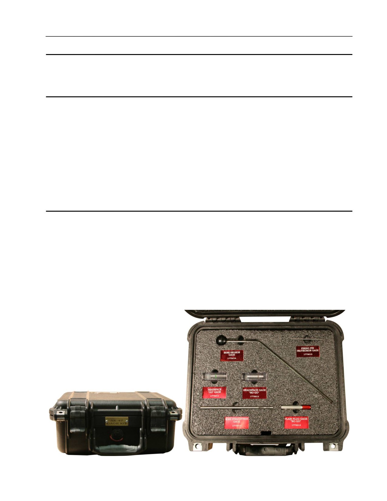
Figure 1. AK-47 Gage Kit.
0021 00-1
TM 8370-50007-IN/2
0021 00
FIRING PIN PROTRUSION GAGE
NOTE
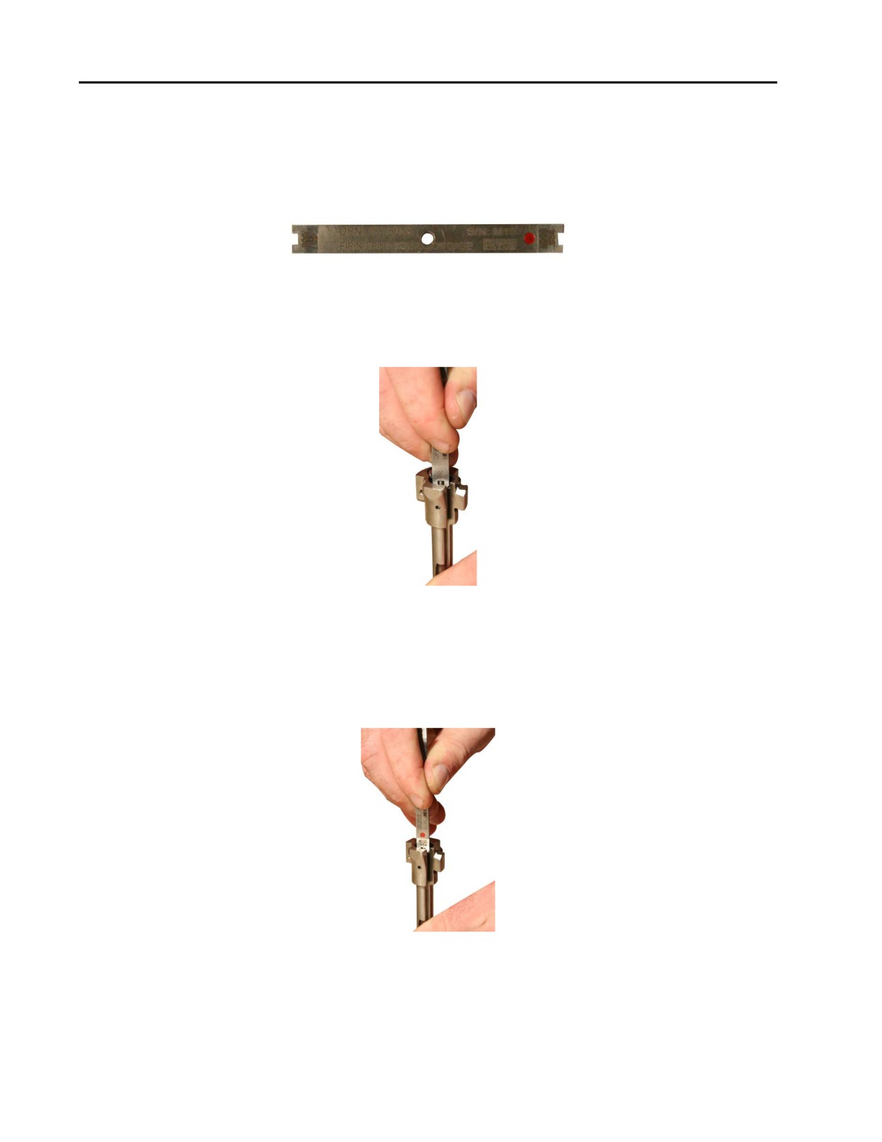
The “go” side of the AK-47 firing pin protrusion gage is the side that reads
“GO.” The “no-go” side of the AK-47 firing pin protrusion gage is the side
that reads “NO-GO” and has a red dot. Refer to Figure 2.
Figure 2. Firing Pin Protrusion Gage.
1. With the rear of the bolt on a flat surface, sweep the “go” side of the gage across the firing pin. The gage
should run freely over the pin. Refer to Figure 3.
Figure 3. Using the “Go” Side of the Firing Pin Protrusion Gage.
2. If the gage catches on the firing pin, replace the firing pin.
3. With the rear of the bolt on a flat surface, sweep the “no-go” side of the gage across the firing pin. The
gage should catch and not move freely over the pin. Refer to Figure 4.
Figure 4. Using the “No-Go” Side of the Firing Pin Protrusion Gage.
4. If the “no-go” side of the gage does not catch on the firing pin, the firing pin is too short and the bolt is
defective.
0021 00-2
TM 8370-50007-IN/2
0021 00
BORE EROSION GAGE
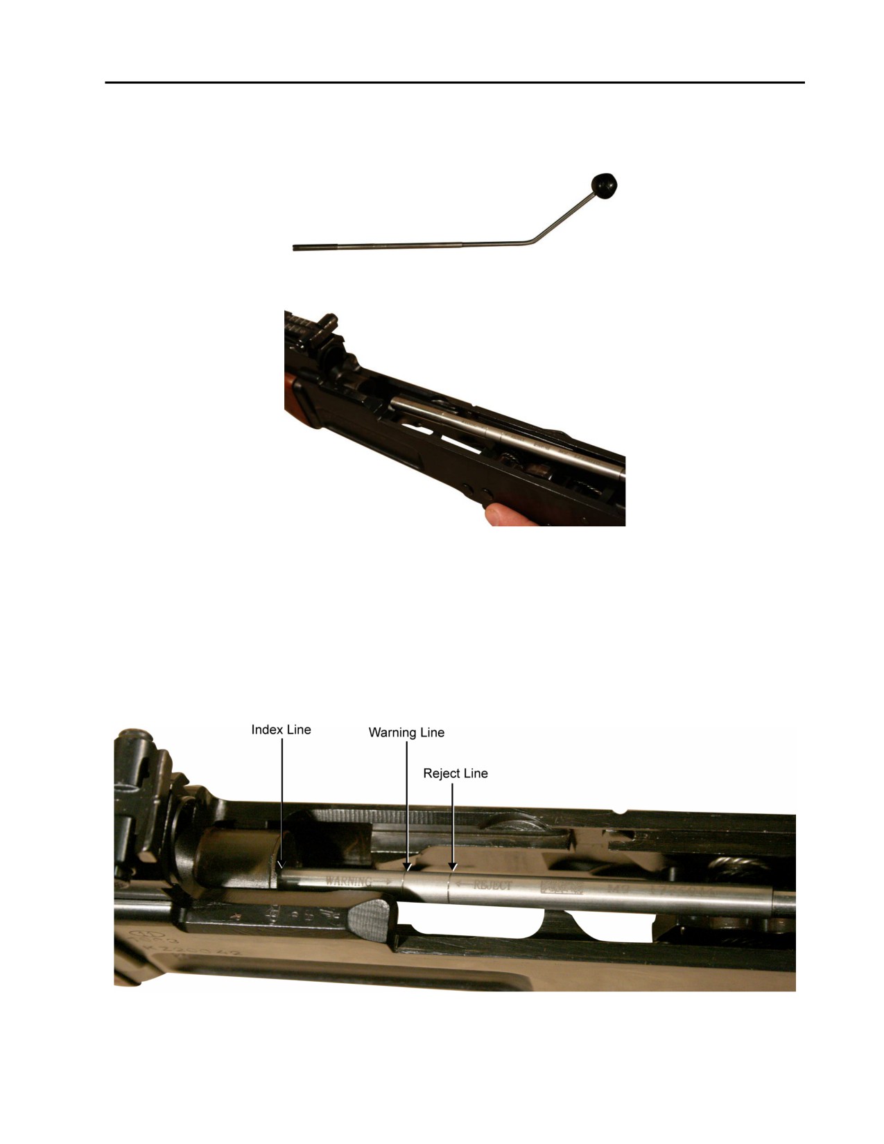
1. Hold the bore erosion gage by the ball handle. Refer to Figure 5. Insert the bore erosion gage into the
bore. Refer to Figure 6.
Figure 5. The Bore Erosion Gage.
Figure 6. Inserting the Bore Erosion Gage into the Breech End of the Barrel.
2. Lightly push the bore erosion gage into the barrel until it seats on the bore.
3. The first line of the bore erosion gage is the warning line. If the bore erosion gage goes into the index line
past the warning line, more frequent gaging should be conducted. Refer to Figure 7.
4. The second line of the bore erosion gage is the reject line. If the bore erosion gage goes into the index line
past the reject line, the barrel is defective and the weapon needs to be replaced. Refer to Figure 7.
Figure 7. Bore Erosion Gage Warning and Reject Lines.
0021 00-3
TM 8370-50007-IN/2
0021 00
BORE STRAIGHTNESS GAGE
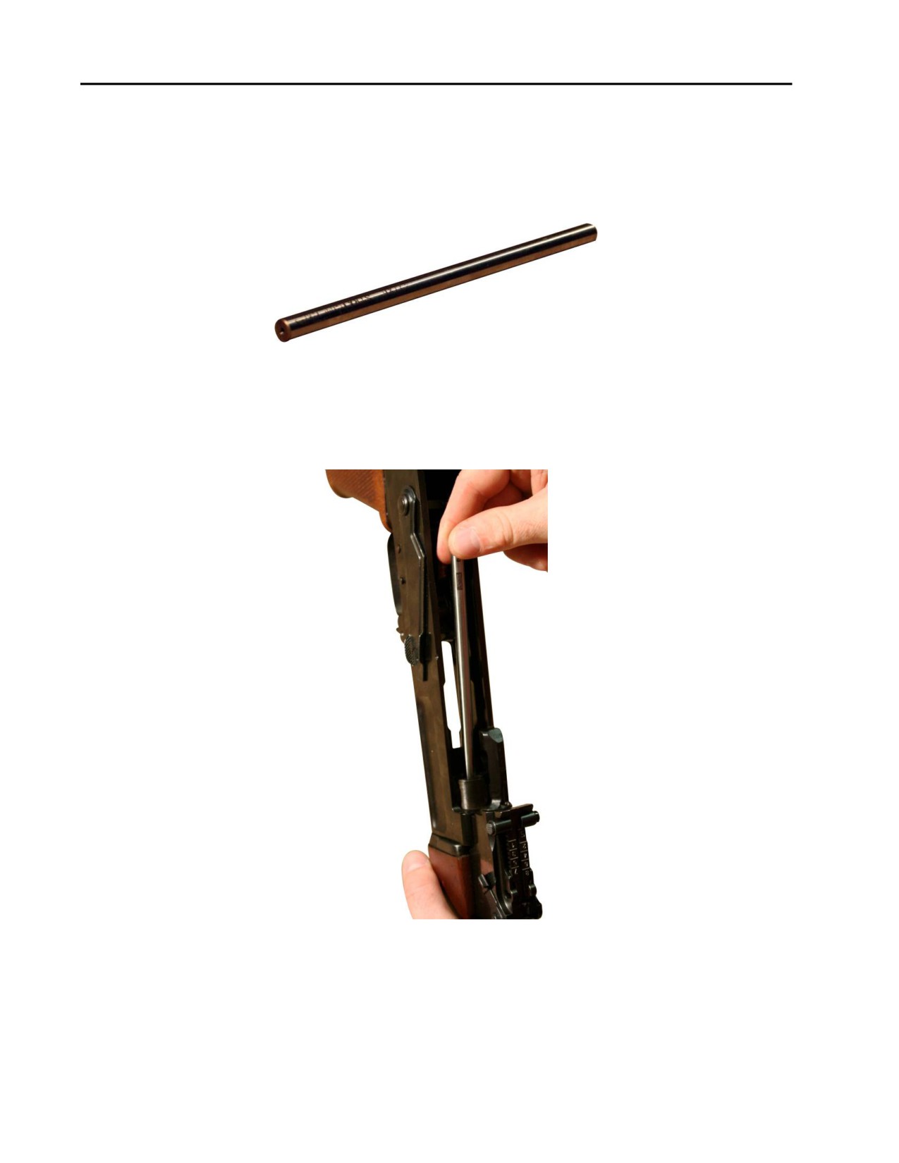
CAUTION
Always drop the straightness gage from the chamber to the muzzle. Do not
let the bore straightness gage fall to the deck. This may damage the gage.
Refer to Figure 8.
Figure 8. Bore Straightness Gage.
1. Holding the weapon vertically, with the buttstock up, place your hand under the muzzle to prevent the
bore straightness gage from hitting the deck and being damaged. Drop the bore straightness gage down
through the barrel, catching it in hand. Refer to Figure 9.
Figure 9. Dropping the Bore Straightness Gage through the Chamber.
0021 00-4
TM 8370-50007-IN/2
0021 00
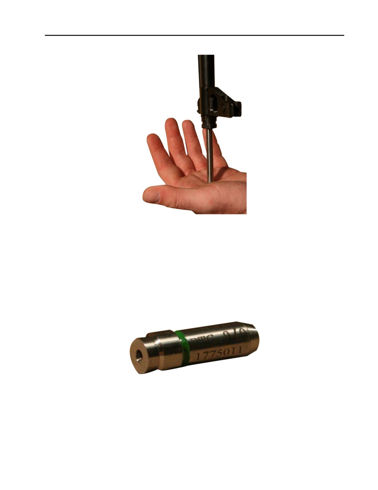
2. The bore straightness gage should fall freely through the barrel and out of the muzzle. Refer to Figure 10.
Figure 10. Bore Straightness Gage Coming out of the Muzzle.
3. If the bore straightness gage does not fall freely, run a patch through the barrel and repeat step 1.
4. If the bore straightness gage again does not pass through the barrel freely, the barrel is defective and the
weapon needs to be replaced.
HEADSPACE “GO” GAGE
CAUTION
When pushing the bolt closed during headspace gaging, be sure to use
LIGHT pressure. Failure to do so may damage the weapon.
Figure 11. The Headspace “Go” Gage.
0021 00-5
TM 8370-50007-IN/2
0021 00
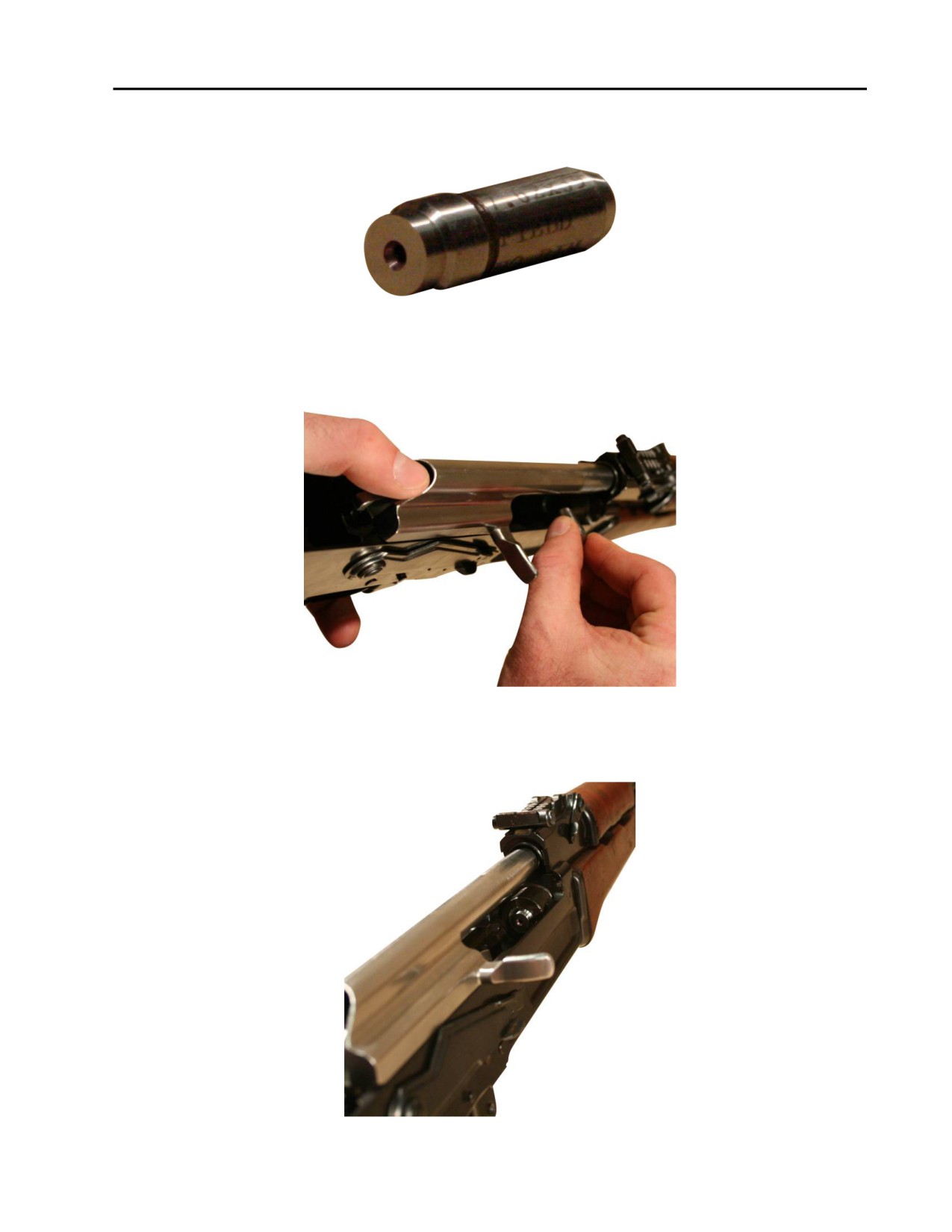
1. Pull the bolt carrier to the rear and insert the headspace “go” gage into the chamber. Refer to Figure 12.
Figure 12. Inserting the Headspace “Go” Gage.
2. Ensure the headspace “go” gage is fully seated in the chamber. Refer to Figure 13.
Figure 13. Headspace “Go” Gage Fully Seated in the Chamber.
3. Using LIGHT pressure, push the bolt carrier forward. The bolt should lock on the headspace “go” gage. If
the bolt does not lock on the “go” gage, replace the bolt and regage. if the second bolt does not either
lock, replace the weapon. Refer to Figure 14.
Figure 14. Bolt Locked.
0021 00-6
TM 8370-50007-IN/2
0021 00
4. Pull the bolt carrier to the rear and remove the headspace “go” gage.
HEADSPACE “NO-GO” GAGE
Figure 15. The Headspace “No-Go” Gage.
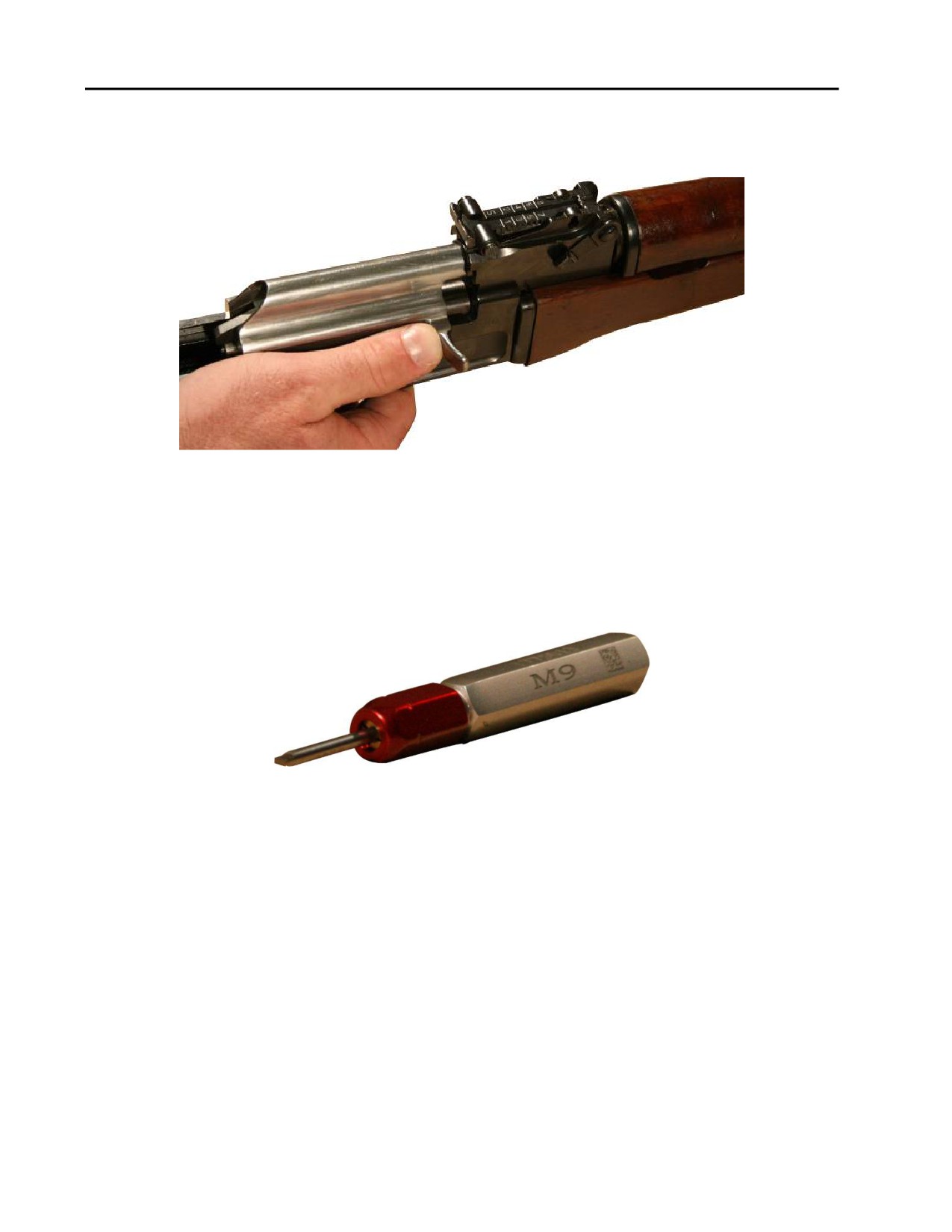
1. Pull the bolt carrier to the rear and insert the headspace “no-go” gage into the chamber. Refer to
Figure 16.
Figure 16. Inserting the Headspace “No-Go” Gage.
2. Ensure the headspace “no-go” gage is fully seated in the chamber. Refer to Figure 17.
Figure 17. Headspace “No-Go” Gage Fully Seated in the Chamber.
0021 00-7
TM 8370-50007-IN/2
0021 00
3. Using LIGHT pressure, push the bolt closed. The bolt should NOT lock on the “no-go” gage. If the bolt
does lock on the “no-go” gage, replace the bolt and regage. If the second bolt also locks, replace the
weapon. Refer to Figure 18.
Figure 18. Bolt NOT Locked.
4. Pull the bolt carrier to the rear and remove the headspace “no-go” gage.
PLAIN PLUG “NO-GO” GAGE
The plain plug “no-go” gage checks for the out-of-round condition of the firing pin hole in the bolt face. Refer
to Figure 19.
Figure 19. Plain Plug “No-Go” Gage.
1. Try to insert the pin of the plain plug “no-go” gage into the firing pin hole in the bolt face by slowly
rotating the gage.
2. If the pin enters the hole at any point, and enters up to the notch on the pin of the plain plug “no-go” gage,
the bolt is defective and needs to be replaced.
END OF WORK PACKAGE
0021 00-8

TM 8370-50007-IN/2
CHAPTER 4
AUXILIARY EQUIPMENT

INTENTIONALLY BLANK
TM 8370-50007-IN/2
0022 00
AUXILIARY EQUIPMENT - GENERAL
GENERAL
The following auxiliary equipment items are used in conjunction with the AK-47 rifle:
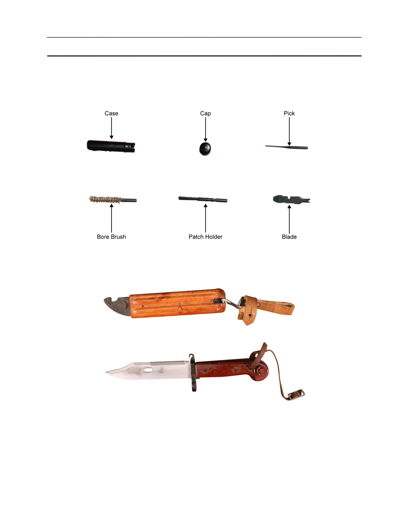
1. Combination tool kit. Refer to Figure 1.
Figure 1. Combination Tool Kit.
2. Bayonet and bayonet scabbard. Refer to Figure 2.
Figure 2. Bayonet and Bayonet Scabbard.
0022 00-1

TM 8370-50007-IN/2
0022 00
3. Sling. Refer to Figure 3.
Figure 3. Sling.
END OF WORK PACKAGE
0022 00-2

TM 8370-50007-IN/2
CHAPTER 5
SUPPORTING INFORMATION

INTENTIONALLY BLANK

TM 8370-50007-IN/2
0023 00
REFERENCES
SCOPE
This work package lists all forms, field manuals, technical manuals, tables, regulations, standards, and
miscellaneous publications referenced in this manual.
TECHNICAL BULLETINS/INSTRUCTION/MANUALS/ORDERS
Preparation for Storage
MCO P4450.7
Weapon Custody Receipt Card
NAVMC 10520
Equipment Repair Order
NAVMC 10245
Memorandum Receipt for Individual Weapons and Accessories
NAVMC 10576
Equipment Repair Order Shopping/Transaction List
NAVMC 10925
Ammunition and Explosives Safety Standards
PAM 385-64
Standards for Overseas Shipment or Domestic Issue of Small Arms, Aircraft Armament,
Towed Howitzers, Mortars, Recoilless Rifles, Rocket Launchers, and Associated Fire
Control Equipment
TB 9-1000-247-34_
Infantry Weapons Gage Calibration Program (IWGCP)
TI 4733-15/11_
Organizational Corrosion Prevention and Control Procedures for USMC Equipment
TM 4795-12/1_
Ground Equipment Record Procedures
TM 4700 -15/1_
Procedures for Destruction of Equipment
TM 750-244-7
Military Use of Cleaner, Lubricant, and Preservative (CLP) for Weapons and
Support Equipment
TM 9150-15/1_
Operators Manual for Rifle, 7.26 mm, AK-47
TM 8370-50007-OR/1
FORMS
Recommended Changes to Technical Publications
NAVMC 10772
Report of Discrepancy (ROD)
SF 364
END OF WORK PACKAGE
0023 00-1/2 blank

INTENTIONALLY BLANK

TM 8370-50007-IN/2
0024 00
EXPENDABLE AND DURABLE ITEMS LIST
SCOPE
Table 1 contains expendable and durable items for the support and operation of the AK-47 rifle.
EXPLANATION OF COLUMNS
1. Column (1) - Item Number. This number is assigned to the entry in the list.
2. Column (2) - National Stock Number (NSN). This is the NSN assigned to an item and is used when
requisitioning the item.
3. Column (3) - Description, CAGEC, and Part Number. This provides other information, if available,
that may be needed to identify the item.
4. Column (4) - Unit of Measure (U/M). This code shows the physical measurement or count of an item,
such as gallon (GAL), pint (PT), dozen (DZ), bundle (BDL), each (EA), bottle (BTL), package (PKG),
book (BK), can (CN), or bale (BE).
Table 1. Expendable and Durable Items for the AK-47 Rifle.
(1)
(2)
(3)
(4)
Item
National Stock Number
Description, CAGEC, and Part Number
U/M
Number
(NSN)
1
1005-00-444-6602
Brush, cleaning, tools and parts
EA
2
6850-00-965-2332
Carbon removing compound
GAL
3
9150-01-102-1473
Cleaner, lubricant, and preservative (CLP)
EA
9150-01-079-6124
CLP - 4 oz (118.30 mL) bottle
BTL
9150-01-054-6453
CLP - 1 pt (0.47 L) bottle
BTL
9150-01-053-6688
CLP - 1 gal (3.78 L) can
CN
4
9920-00-292-9946
Cleaner, tobacco pipe, cotton turf, wire core, pipe
PKG
cleaner (36 per pkg)
5
5350-00-221-0872
Cloth, abrasive
SH
6
Gloves, chemical and oil protective
8415-00-823-7458
Size 9
PR
8415-00-823-7459
Size 10
PR
8415-00-823-7460
Size 11
PR
7
9150-01-260-2534
Lubricant, solid film
CN
16 oz (473.18 mL) spray can
8
9150-00-292-9689
Lubricant, arctic, weapons (LAW) 1 qt (0.95 L) can
CN
0024 00-1

TM 8370-50007-IN/2
0024 00
Table 1. Expendable and Durable Items for the AK-47 Rifle - Continued.
(1)
(2)
(3)
(4)
Item
National Stock Number
Description, CAGEC, and Part Number
U/M
Number
(NSN)
9
Lubricant, semi-fluid, automatic weapons, (LSA)
9150-00-935-6597
2 oz (59.15 mL) plastic bottle
BTL
9150-00-889-3522
4 oz (118.30 mL) plastic bottle
BTL
9150-00-687-4241
1 qt (0.95 L) can
CN
9150-00-753-4686
1 gal. (3.79 L) can
CN
10
3990-00-795-3595
Pan, wash (box, tote)
EA
11
6850-00-826-0981
Penetrant kit
KT
12
7290-00-205-1711
Rag, wiping 50 lb (22.68 kg) bdl
BDL
13
6850-00-281-1985
Solvent, dry cleaning 1 gal. (3.79 L) can
CN
14
Solvent, general MIL-PRF-680 Type II
6850-01-474-2319
1 gal. (3.79 L)
GAL
6850-01-474-2317
5 gal. (18.93 L)
GAL
6850-01-474-2316
55 gallon drum
DR
15
1005-00-288-3565
Swab, cleaning, small arms (7.62 patch)
SH
END OF WORK PACKAGE
0024 00-2

TM 8370-50007-IN/2
0025 00
TOOL IDENTIFICATION LIST (INCLUDES SPECIAL TOOLS)
SCOPE
This work package lists the common tools and special tools authorized for support of the AK-47 rifle.
EXPLANATION OF COLUMNS
1. Column (1) - Item Number. This column indicates the number of the figure, if available, that shows the
item.
2. Column (2) - Item Name. This column lists the item by noun nomenclature and other descriptive
features.
3. Column (3) - National Stock Number (NSN). This column lists the NSN assigned to an item and is used
when requisitioning the item.
4. Column (4) - Part Number. This column indicates the primary number used by the manufacturer which
controls the design and characteristics of the item by means of its engineering drawings, specifications,
standards, and inspection requirements to identify an item or range of items.
5. Column (5) - Unit of Measure (U/M). This column shows the count of an item when issued, such as
each (EA), set (Set), package (PKG), book (BK), or bale (BE).
Table 1. Tools Identification List for AK-47 Rifle.
(1)
(2)
(3)
(4)
(5)
Item
Item Name
National Stock Number (NSN)
Part
U/M
Number
Number
1
Gage kit, AK-47
TBD
N/A
Set
2
Gage, bore erosion
TBD
1775016
EA
3
Gage, bore straightness
TBD
1775014
EA
4
Gage, firing pin protrusion
TBD
1775015
EA
5
Gage, headspace “go”
TBD
1775011
EA
6
Gage, headspace “no go”
TBD
1775012
EA
7
Gage, plain plug “no go”
TBD
1775013
EA
8
Tool, front sight adjustment
TBD
N/A
EA
9
Tool, scraper
TBD
N/A
EA
10
Tool kit, USMC E7900
5180-01-504-5663
TK-2111
EA
0025 00-1
TM 8370-50007-IN/2
0025 00
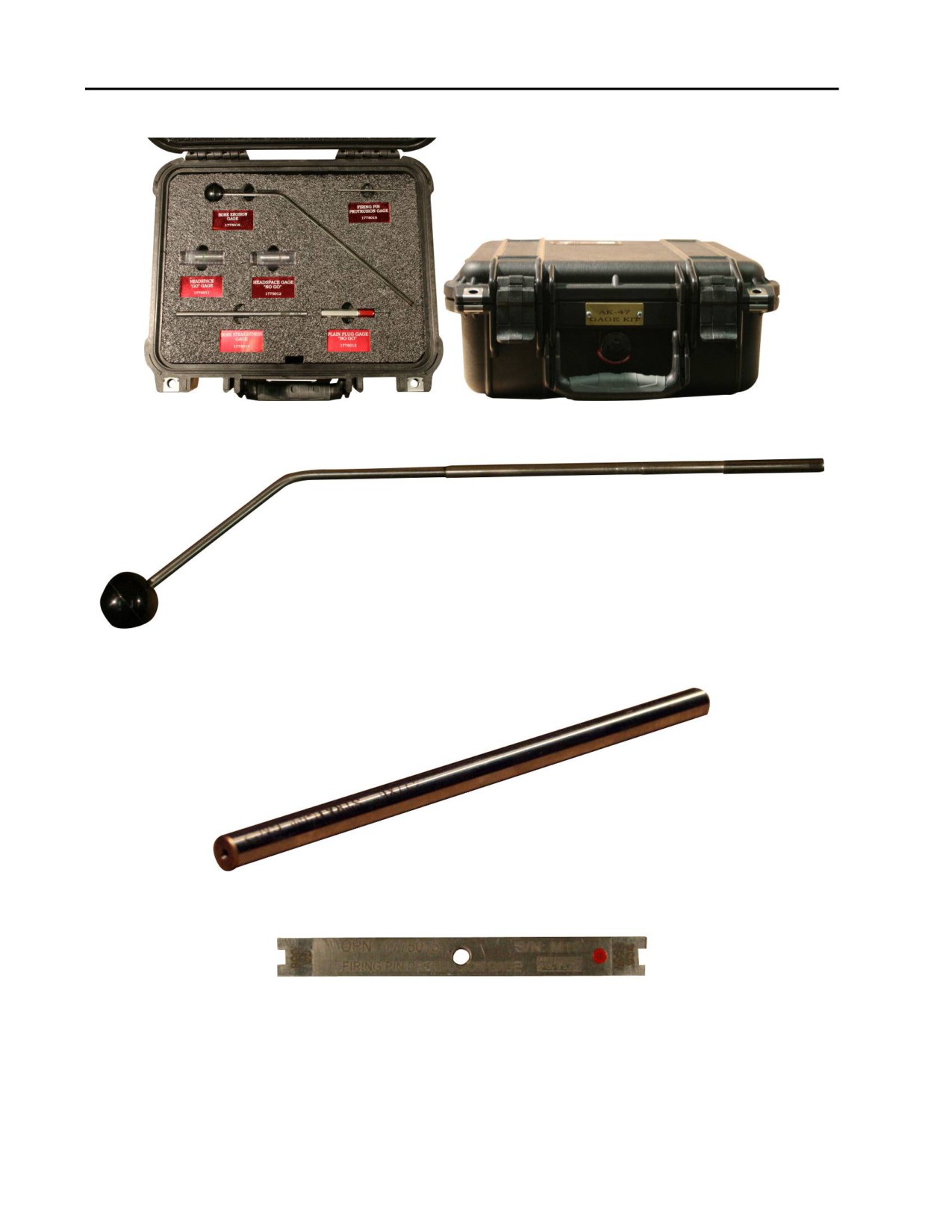
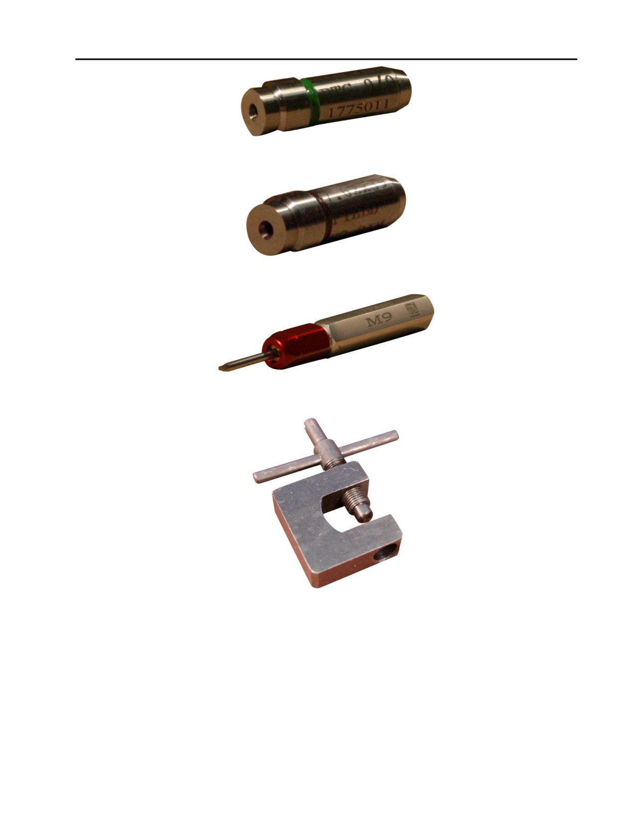
Figures 1 through 8 represent the items 1 through 8 listed in Table 1.
Figure 1. Gage Kit, AK-47.
Figure 2. Gage, Bore Erosion (1775016).
Figure 3. Gage, Bore Straightness (1775014).
Figure 4. Gage, Firing Pin Protrusion (1775015).
0025 00-2
TM 8370-50007-IN/2
0025 00
Figure 5. Gage, Headspace “Go” (1775011).
Figure 6. Gage, Headspace “No-Go” (1775012)
Figure 7. Gage, Plain Plug “No-Go” (1775013).
Figure 8. Tool, Front Sight Adjustment
END OF WORK PACKAGE
0025 00-3/4 blank

INTENTIONALLY BLANK

TM 8370-50007-IN/2
0026 00
REPAIR PARTS LIST (RPL) INTRODUCTION
SCOPE
This repair parts list (RPL) authorizes spares, repair parts, and other special support equipment required for
the performance of organizational maintenance of the AK-47 rifle. It authorizes the requisitioning, issue, and
disposition of spares and repair parts indicated by the source, maintenance, and recoverability (SMR) codes.
Parts lists are composed of functional groups listed in figure and item number sequence.
EXPLANATION OF COLUMNS
1. Item No. (Column 1). The item number indicates the number used to identify items called out in an
illustration.
2. SMR Code (Column 2). The SMR code is a five-position code containing supply and requisition
information, maintenance level authorization criteria, and disposition instructions as shown in the
following manner. Refer to Table 1 for an explanation of the five positions in the SMR code. Refer to
Tables 2-5 for explanations of the source codes, maintenance codes, and recoverability codes that make
up the SMR code.
Table 1. SMR Code Positions.
Source Code
Maintenance Code
Recoverability Code
XX
X
X
X
1st and 2nd positions
3rd position
4th position
5th position
How to obtain an item.
Who can install, replace,
Who can perform
Who determines the disposition
or use the item.
repair* on the item.
action on an unserviceable item.
NOTE
Complete repair: maintenance capacity, capability, and authority to perform
all corrective maintenance tasks of the repair function in a user environment
in order to restore serviceability to a failed item.
a. Source Code. The source code indicates how to obtain an item needed for maintenance, repair, or
overhaul of equipment and is entered in the first and second positions of the SMR code as shown in
Table 2.
Table 2. Source Codes.
Code
Application/Explanation
PA
Item: Stocked
PB
Item: Stocked, insurance
PC
Item: Stocked, deteriorative
PD
Item: Support, initial issue or outfitting and stocking only for additional initial issue.
PE
Equip: Support, stocked, initial issue, or outfitting of specified maintenance activities (also
used for “special tools”).
PF
Equip: Support, non-stocked, and centrally procured on demand.
PG
Item: Stocked, for sustained support, uneconomical to produce at later time.
0026 00-1

TM 8370-50007-IN/2
0026 00
Table 2. Source Codes - Continued.
Code
Application/Explanation
KD
Items with these codes are not to be requested/requisitioned individually. These items are
part of a kit authorized to the maintenance level indicated in the 3rd position of the SMR
KF
code. The complete kit must be requisitioned and applied for this weapon.
KB
MO
Items with these codes are not to be requisitioned individually. They must be made from
bulk material identified by the part number in the description column. No bulk material items
MF
are applicable for this weapon.
MH
ML
MD
AO
Items with these codes are not to be requested/requisitioned individually. The parts that
make the assembled items must be requisitioned, fabricated, or assembled at the level of
AF
maintenance indicated by source code. If the 3rd position code of the SMR code authorizes
AH
the item to be replaced, but the source code indicates the item is assembled at a higher
AD
level, order the item from the higher level of maintenance.
XA
Do not requisition an XA-coded item. Order its next higher assembly. (Also refer to the
NOTE below).
XB
If an XB item is not available from salvage, order it using the CAGEC and part number
given.
XC
XC installation drawing, diagram, instruction sheet, and field service drawing identified by
the manufacturer’s part number.
XD
XD are items not stocked. Order an XD-coded item through normal supply channels using
the CAGEC and part number given.
NOTE
Cannibalizing or controlled exchange, when authorized, may be used as a
source of supply for items with the above source codes, except for those
coded XA. Items coded PC are subject to deterioration.
b. Maintenance Code. The maintenance code indicates the levels of maintenance authorized to use and
repair the support items. The maintenance codes are entered in the third and fourth positions of the
SMR code format as follows:
(1) The maintenance code entered in the third position indicates the lowest maintenance level
authorized to remove, replace, and use an item. Refer to Table 3 for an explanation of the
maintenance code that indicates the level of maintenance required.
Table 3. Third Position Maintenance Codes.
Code
Application/Explanation
C
Crew or operator maintenance done within unit maintenance.
O
Organizational level can remove, replace, and use the item.
F
Third echelon can remove, replace, and use the item.
H
Fourth echelon can remove, replace, and use the item.
L
Specialized repair activity can remove, replace, and use the item.
D
Depot level can remove, replace, and use the item.
0026 00-2
TM 8370-50007-IN/2
0026 00
(2) The maintenance code entered in the fourth position indicates whether the item is to be repaired at
the lowest maintenance level with the capability to perform complete repair (i.e., all authorized
maintenance functions).
NOTE
Some limited repair may be done on the item at a lower level of maintenance,
if authorized by the SMR codes.
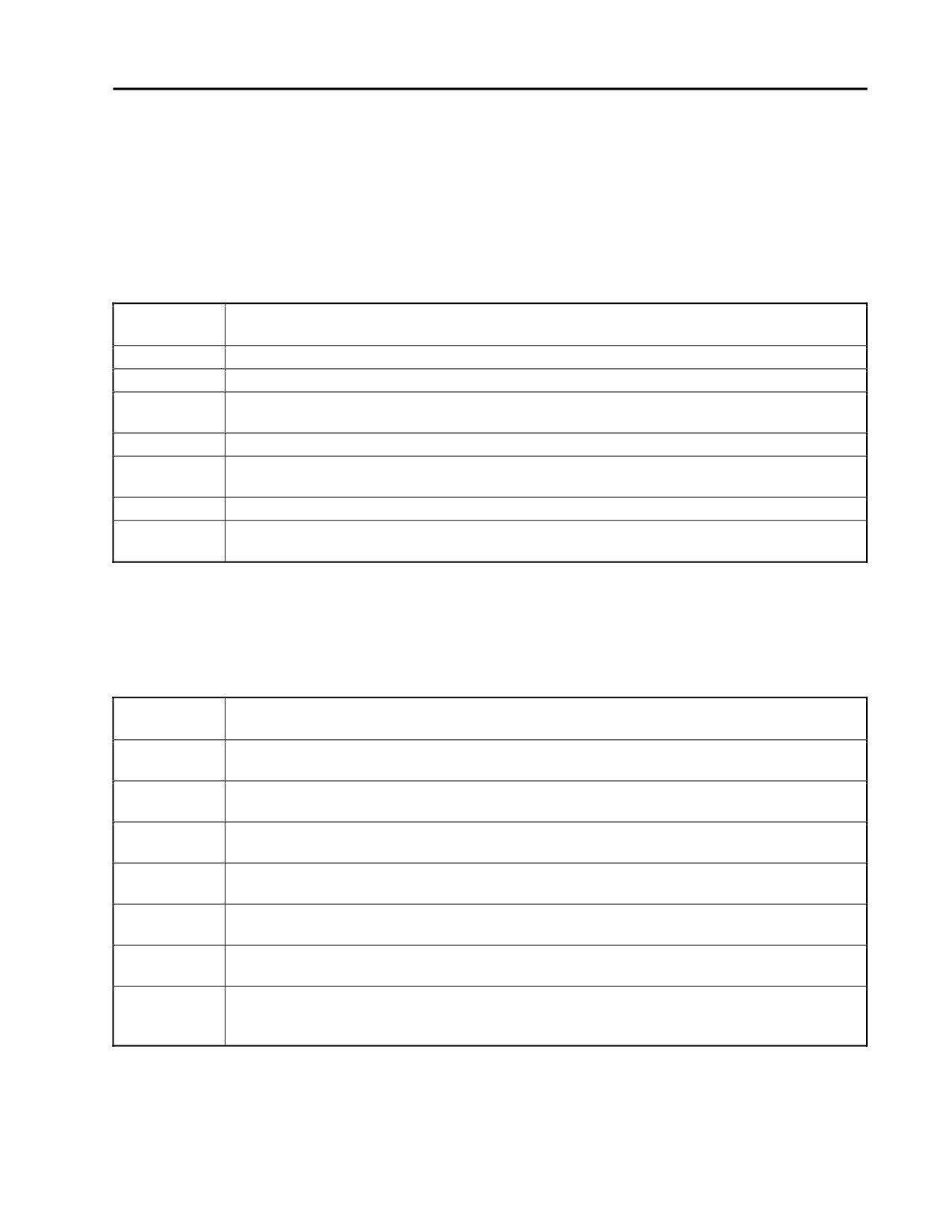
Table 4. Fourth Position Maintenance Codes.
Code
Application/Explanation
O
Organizational level is the lowest level that can completely repair the item.
F
Intermediate third echelon is the lowest level that can completely repair the item.
H
The lowest maintenance level capable of complete repair of the support item is the general
support level.
D
Depot level is the lowest level that can completely repair the item.
L
Specialized repair activity (designated the specialized repair activity) is the lowest level that
can completely repair the item.
Z
Non-repairable. No repair is authorized.
B
No repair authorized. No parts or special tools are authorized for maintenance of a B-coded
item. However, the item may be reconditioned by adjusting or lubricating at the user level.
c. Recoverability Code. The recoverability code is assigned to support items to indicate the disposition
action on unserviceable items. The recoverability code is entered in the fifth position of the SMR
code format. Refer to Table 4 for code explanations.
Table 5. Recoverability Codes.
Code
Application/Explanation
Z
Non-repairable item. When unserviceable, condemn and dispose of the item at the level of
maintenance shown in the third position of the SMR code.
O
Repairable item. When uneconomically repairable, condemn and dispose of at the
organizational level.
F
Repairable item. When uneconomically repairable, condemn and dispose of at the third
echelon level.
H
Repairable item. When uneconomically repairable, condemn and dispose of at the fourth
echelon level.
D
Repairable item. When uneconomically repairable, condemn and dispose of at the depot
level.
L
Repairable item. Condemnation and disposal not authorized below specialized repair
activity.
A
Item requires special handling or condemnation procedures because of specific reasons
(e.g., precious metal content, high dollar value, or hazardous material). Refer to the
appropriate manuals/directives for specific instructions.
3.
NSN (Column 3). The national stock number for the item is listed in this column.
4.
CAGEC (Column 4). The commercial and government entity code is a 5-digit code used to identify the
manufacturer, distributor, or government activity that supplies the item.
0026 00-3

TM 8370-50007-IN/2
0026 00
5. Part Number (Column 5). Indicates the primary number used by the manufacturer that controls the
design and characteristics of the items by means of its engineering drawings, specifications, standards,
and inspection requirements to identify an item or range of items.
NOTE
When an NSN is used to requisition an item, the item received may be a
different part number from the part ordered.
6. Item Identification (Column 6). This column includes the following information:
a. Federal item name and, when required, a minimum description identifying the items.
b. The statement END OF FIGURE appears just below the last item description in columns 6 and 7 for a
given figure.
7. Qty (Column 7). The quantity (Qty) column indicates the quantity of the item used in the breakout
shown on the illustration figure, which is prepared for a functional group, sub-functional group, or an
assembly. The letter V appearing in this column in lieu of a quantity indicates the quantity is variable and
may vary from application to application.
HOW TO LOCATE REPAIR PARTS
WP 0027 00 contains the repair parts and special tools listings.
1. Unknown national stock number (NSN) or part number.
a. Identify the item from the illustration and note the item number.
b. Look in the repair parts list (RPL) for the figure and item numbers. The NSNs and part numbers are
on the same lines as the associated item numbers.
2. Known NSN or part number.
a. Using the NSN or part number, locate the item in the RPL. Note the pertinent information.
b. Verify the identity of the item.
END OF WORK PACKAGE
0026 00-4

INTENTIONALLY BLANK
TM 8370-50007-IN/2
0027 00
REPAIR PARTS LIST (RPL)
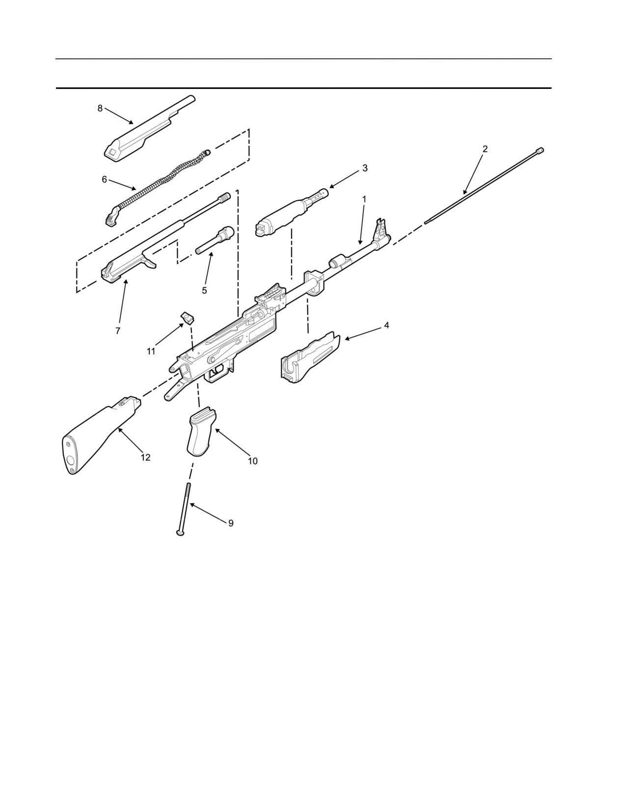
Figure 1. AK-47 Rifle.
0027 00-1 blank/2

TM 8370-50007-IN/2
0027 00
Table 1. AK-47 Rifle.
(1)
(2)
(3)
(4)
(5)
(6)
(7)
Item
SMR
NSN
CAGEC
Part
Description and Usable on
Qty.
Codes (UOC)
No.
Code
Number
Figure 1. AK-47 rifle
1
PAOZZ
TBD
TBD
TBD
Assembly, receiver
1
(see Figure 2 for breakdown)
2
PAOZZ
TBD
TBD
TBD
Rod, cleaning
1
3
PAOZZ
TBD
TBD
TBD
Handguard, upper and tube, gas
1
4
PAOZZ
TBD
TBD
TBD
Handguard, lower
1
5
PAOZZ
TBD
TBD
TBD
Assembly, bolt
1
(see Figure 3 for breakdown)
6
PAOZZ
TBD
TBD
TBD
Assembly, recoil spring and
1
guide rod
(see Figure 3 for breakdown)
7
PAOZZ
TBD
TBD
TBD
Assembly, bolt carrier
1
(see Figure 3 for breakdown)
8
PAOZZ
TBD
TBD
TBD
Cover, top
1
9
PAOZZ
TBD
TBD
TBD
Screw, pistol grip
1
10
PAOZZ
TBD
TBD
TBD
Grip, pistol
1
11
PAOZZ
TBD
TBD
TBD
Block. mounting, pistol grip
1
screw
12
PAOZZ
TBD
TBD
TBD
Assembly, buttstock, fixed
1
(see Figure 5 for breakdown)
End of figure
0027 00-3
TM 8370-50007-IN/2
0027 00
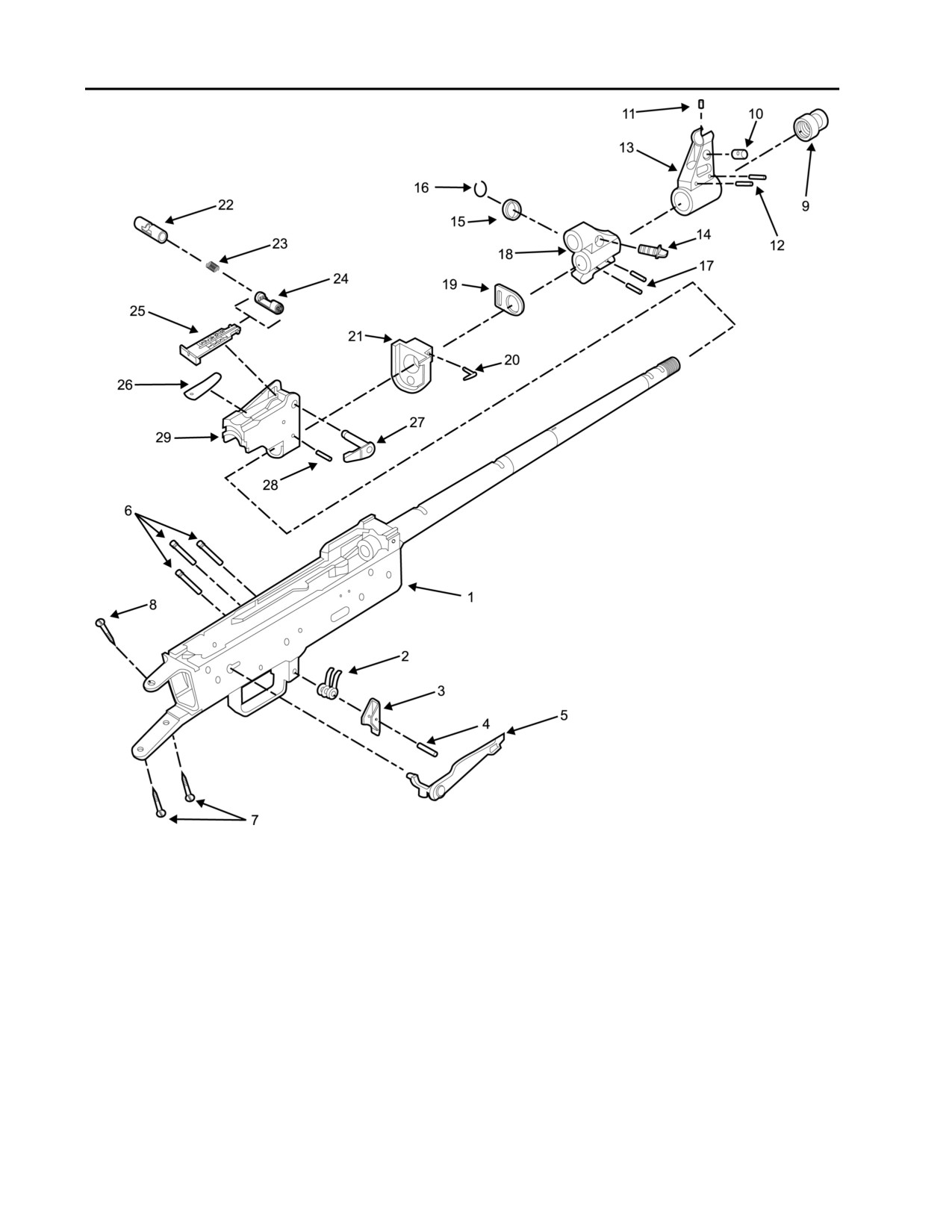
Figure 2. Receiver Assembly.
0027 00-4

TM 8370-50007-IN/2
0027 00
Table 2. Receiver Assembly.
(1)
(2)
(3)
(4)
(5)
(6)
(7)
Item
SMR
NSN
CAGEC
Part
Description and Usable on
Qty.
Codes (UOC)
No.
Code
Number
Figure 2. Receiver assembly
1
PAOZZ
TBD
TBD
TBD
Receiver
1
2
PAOZZ
TBD
TBD
TBD
Spring, magazine release
1
3
PAOZZ
TBD
TBD
TBD
Release, magazine
1
4
PAOZZ
TBD
TBD
TBD
Pin, magazine release
1
5
PAOZZ
TBD
TBD
TBD
Lever, selector
1
6
PAOZZ
TBD
TBD
TBD
Pin, retaining, trigger assembly
3
7
PAOZZ
TBD
TBD
TBD
Screw, buttstock, lower
2
8
PAOZZ
TBD
TBD
TBD
Screw, buttstock, upper
1
9
PAOZZ
TBD
TBD
TBD
Protector, thread
1
10
PAOZZ
TBD
TBD
TBD
Drum, windage, front sight
1
11
PAOZZ
TBD
TBD
TBD
Post, front sight
1
12
PAOZZ
TBD
TBD
TBD
Pin, base, front sight
2
13
PAOZZ
TBD
TBD
TBD
Base, front sight
1
14
PAOZZ
TBD
TBD
TBD
Selector, gas
1
15
PAOZZ
TBD
TBD
TBD
Collar, gas
1
16
PAOZZ
TBD
TBD
TBD
Clip, “C”
1
17
PAOZZ
TBD
TBD
TBD
Pin, gas block
2
18
PAOZZ
TBD
TBD
TBD
Block, gas
1
19
PAOZZ
TBD
TBD
TBD
Swivel, sling, front
1
20
PAOZZ
TBD
TBD
TBD
Lever, locking, lower handguard
1
ring
21
PAOZZ
TBD
TBD
TBD
Ring, lower handguard
1
22
PAOZZ
TBD
TBD
TBD
Slide, rear sight assembly
1
23
PAOZZ
TBD
TBD
TBD
Spring, slide, rear sight
1
assembly
24
PAOZZ
TBD
TBD
TBD
Catch, slide, rear sight assembly
1
25
PAOZZ
TBD
TBD
TBD
Sight, leaf, rear sight assembly
1
26
PAOZZ
TBD
TBD
TBD
Spring, leaf, rear sight
1
27
PAOZZ
TBD
TBD
TBD
Lever, locking, upper handguard
1
28
PAOZZ
TBD
TBD
TBD
Base, rear sight
1
29
PAOZZ
TBD
TBD
TBD
Pin, retaining, rear sight base
1
End of figure
0027 00-5
TM 8370-50007-IN/2
0027 00
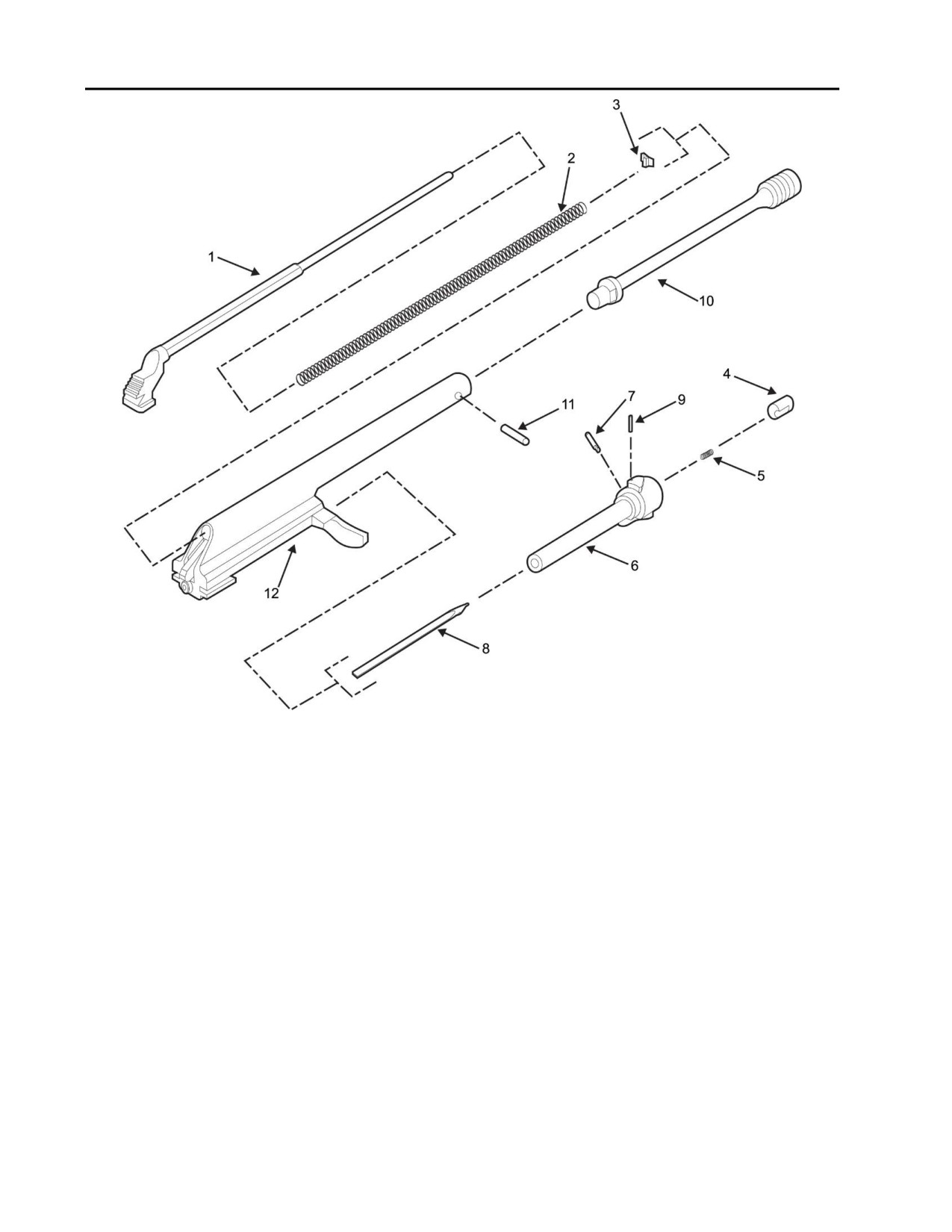
Figure 3. Recoil Spring and Guide Rod Assembly, Bolt Assembly, and
Bolt Carrier Assembly.
0027 00-6

TM 8370-50007-IN/2
0027 00
Table 3. Recoil Spring and Guide Rod Assembly, Bolt Assembly, and Bolt Carrier
Assembly.
(1)
(2)
(3)
(4)
(5)
(6)
(7)
Item
SMR
NSN
CAGEC
Part
Description and Usable on
Qty.
Codes (UOC)
No.
Code
Number
Figure 3. Bolt carrier assembly,
bolt assembly, and recoil and
guide rod assembly.
1
PAOZZ
TBD
TBD
TBD
Assembly, Recoil Spring and
Guide Rod
2
PAOZZ
TBD
TBD
TBD
Rod, guide
1
3
PAOZZ
TBD
TBD
TBD
Spring, recoil
1
4
PAOZZ
TBD
TBD
TBD
Cam, recoil spring
1
Assembly, Bolt
5
PAOZZ
TBD
TBD
TBD
Extractor
1
6
PAOZZ
TBD
TBD
TBD
Spring, extractor
1
7
PAOZZ
TBD
TBD
TBD
Bolt
1
8
PAOZZ
TBD
TBD
TBD
Pin, retaining, extractor, grooved
1
9
PAOZZ
TBD
TBD
TBD
Pin firing
1
10
PAOZZ
TBD
TBD
TBD
Pin, retaining, firing pin
1
Assembly, bolt carrier
11
PAOZZ
TBD
TBD
TBD
Piston, gas
1
12
PAOZZ
TBD
TBD
TBD
Pin, retaining, gas piston
1
13
PAOZZ
TBD
TBD
TBD
Carrier, bolt
1
End of figure
0027 00-7
TM 8370-50007-IN/2
0027 00
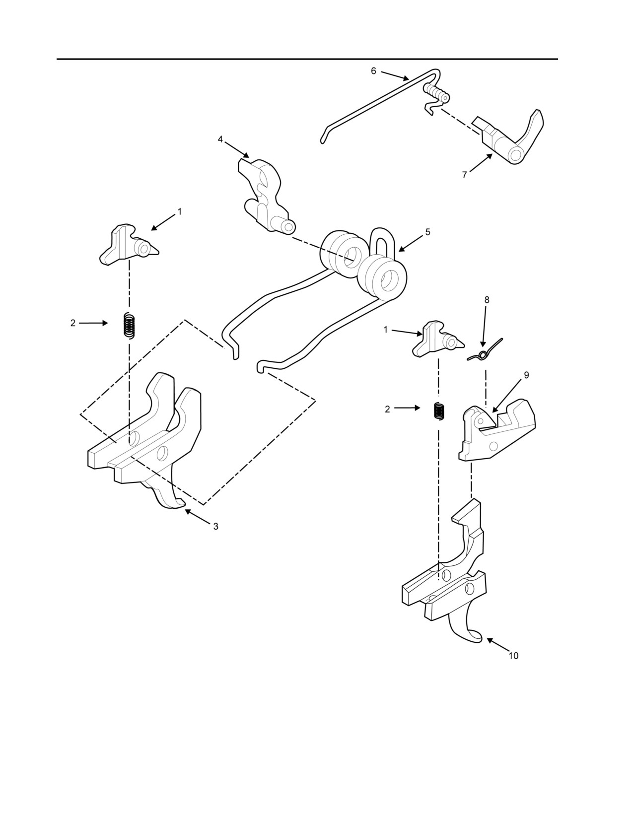
Figure 4. Trigger Assembly.
0027 00-8

TM 8370-50007-IN/2
0027 00
Table 4. Trigger Assembly.
(1)
(2)
(3)
(4)
(5)
(6)
(7)
Item
SMR
NSN
CAGEC
Part
Description and Usable on
Qty.
Codes (UOC)
No.
Code
Number
Figure 4. Trigger assembly.
1
PAOZZ
TBD
TBD
TBD
Disconnector
1
2
PAOZZ
TBD
TBD
TBD
Spring, disconnector
1
3
PAOZZ
TBD
TBD
TBD
Trigger, hooked, double
1
4
PAOZZ
TBD
TBD
TBD
Hammer
1
5
PAOZZ
TBD
TBD
TBD
Spring, hammer
1
6
PAOZZ
TBD
TBD
TBD
Spring, auto sear
1
7
PAOZZ
TBD
TBD
TBD
Sear, auto
1
8
PAOZZ
TBD
TBD
TBD
Spring, interrupter
1
9
PAOZZ
TBD
TBD
TBD
Interrupter
1
10
PAOZZ
TBD
TBD
TBD
Trigger, hooked, single
1
End of figure
0027 00-9
TM 8370-50007-IN/2
0027 00
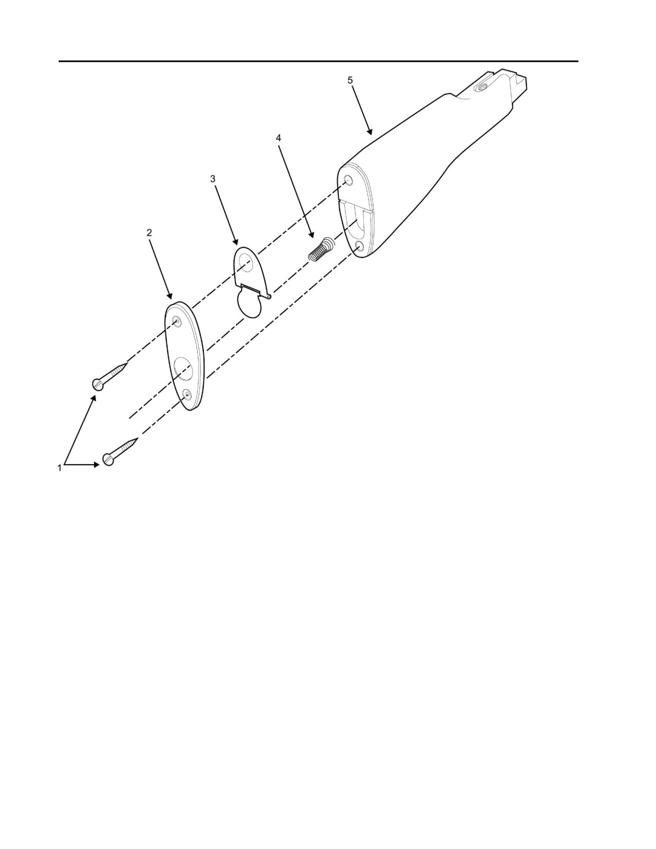
Figure 5. Fixed Buttstock Assembly
0027 00-10
TM 8370-50007-IN/2
0027 00
Table 5. Fixed Buttstock Assembly.
(1)
(2)
(3)
(4)
(5)
(6)
(7)
Item
SMR
NSN
CAGEC
Part
Description and Usable on
Qty.
Codes (UOC)
No.
Code
Number
Figure 5. Fixed buttstock
assembly.
1
PAOZZ
TBD
TBD
TBD
Screw, buttplate
2
2
PAOZZ
TBD
TBD
TBD
Buttplate
1
3
PAOZZ
TBD
TBD
TBD
Trapdoor, buttplate
1
4
PAOZZ
TBD
TBD
TBD
Spring, buttplate
1
5
PAOZZ
TBD
TBD
TBD
Buttstock, fixed
1
End of figure
END OF WORK PACKAGE
0027 00-11/12 blank

INTENTIONALLY BLANK

TM 8370-50047-IN/6
INDEX
Subject
WP Sequence No. - Page No.
A
Abbreviations and Acronyms, List of
0001 00-2
Auxiliary Equipment - General
0022 00-1
B
Bolt Assembly
0012 00-1
Bolt Carrier Assembly and Bolt Assembly
0011 00-1
D
Disassembly of Weapon
0010 00-1
C
Caution Summary
f
Cleaning Instructions, General
0009 00-1
E
Equipment Description and Data
0002 00-1
Expendable and Durable Items List
0024 00-1
F
Final Inspection and Function Test
0020 00-1
Fixed Buttstock Assembly
0015 00-1
Function Check
0017 00-1
G
Gaging Procedures
0021 00-1
General Information
0001 00-1
General Maintenance Instructions
0009 00-1
H
How to Use
iii
L
List of Abbreviations and Acronyms
0001 00-2
Lubrication Instructions, General
0009 00-4
INDEX - 1

TM 8370-50047-IN/6
INDEX
Subject
WP Sequence No. - Page No.
P
Preventive Maintenance Checks and Services (PMCS), Including
Lubrication Instructions,
0008 00-1
Principles of Operation
0003 00-1
R
Rear Sight Assembly
0014 00-1
Reassembly of Weapon
0016 00-1
Receiver Assembly
0013 00-1
References
0023 00-1
Repair Parts List (RPL)
0027 00-1
Repair Parts List (RPL) Introduction
0026 00-1
S
Service Upon Receipt
0007 00-1
Side Folding Buttstock Assembly
0013 00-16
Storage
0019 00-1
Stowage
0018 00-1
T
Tool Identification List (Includes Special Tools)
0025 00-1
Troubleshooting Introduction
0004 00-1
Troubleshooting Procedures
0006 00-1
Troubleshooting Symptom Index
0005 00-1
U
Under Folding Buttstock Assembly
0013 00-13
W
Warning Summary
a
INDEX - 2

TM 8370-50007-OR/1
U.S. MARINE CORPS TECHNICAL MANUAL
OPERATOR’S MANUAL WITH COMPONENTS LIST
FOR
RIFLE, 7.62 MM, AK-47, NSN: 1005-LL-MUS-2940, P/N TBD
DISTRIBUTION STATEMENT C: DISTRIBUTION AUTHORIZED TO U.S. GOVERNMENT AGENCIES AND THEIR
CONTRACTORS. THIS PUBLICATION IS REQUIRED FOR ADMINISTRATION AND OPERATION PURPOSES. OTHER
REQUESTS FOR THIS DOCUMENT MUST BE REFERRED TO COMMANDER, MARINE CORPS SYSTEMS COMMAND
(PG-13, PM IW), QUANTICO, VA. 22134-6050.
DESTRUCTION NOTICE: DESTROY BY ANY METHOD THAT WOULD PREVENT DISCLOSURE OF CONTENTS OR
RECONSTRUCTION OF THE DOCUMENTS.
FOR OFFICIAL USE ONLY
DECEMBER 2009
PCN 184 837000 00

DEPARTMENT OF THE NAVY
Headquarters, U.S. Marine Corps
Washington, DC 20380-0001
31 December 2009
1. This Technical Manual (TM), authenticated for Marine Corps use and effective upon receipt, describes the technical
characteristics and components for the rifle, 7.62 mm, AK-47, NSN: 1005-LL-MUS-2940.
2. Submit notice of discrepancies or suggested changes on NAVMC 10772. The NAVMC may be submitted via the Internet using
website https://pubs.ala.usmc.mil/front.htm, scrolling down to the NAVMC 10772 Tracking Program and following instructions
provided. It may also be submitted by electronic mail to mbmatcommarcorlogbases@logcom.usmc.mil, or by mailing a paper
copy of NAVMC 10772 addressed to: Commanding General, Marine Corps Systems Command, Attn: Assistant Commander
Acquisition and Logistics (LOG/TP), 814 Radford Blvd., Albany, Georgia 31704-0343.
BY DIRECTION OF THE COMMANDANT OF THE MARINE CORPS
OFFICIAL:
MARK T. BRINKMAN
Program Manager, IW, PG-13
Marine Corps Systems Command
Quantico, Virginia
DISTRIBUTION: PCN 184 837000 00

LIST OF EFFECTIVE PAGES/WORK PACKAGES
Date of issue for original manual is: 31 December 2009.
TOTAL NUMBER OF PAGES FOR FRONT AND REAR MATTER IS 24 AND TOTAL NUMBER OF
WORK PACKAGES IS 21 CONSISTING OF THE FOLLOWING:
Page/WP No.
Change No.
Page/WP No.
Change No.
Page/WP No.
Change No.
Front Cover
0
WP 0008 00 (2 pgs)
0
WP 0020 00 (2 pgs)
0
A through B
0
WP 0009 00 (4 pgs)
0
WP 0021 00 (8 pgs)
0
a through f
0
Chapter 4 title page
0
Index (2 pgs)
0
i though viii
0
WP 0010 00 (4 pgs)
0
Chapter 1 title page
0
WP 0011 00 (2 pgs)
0
WP 0001 00 (2 pgs)
0
WP 0012 00 (20 pgs)
0
WP 0002 00 (10 pgs)
0
WP 0013 00 (6 pgs)
0
WP 0003 00 (4 pgs)
0
WP 0014 00 (12 pgs)
0
Chapter 2 title page
0
WP 0015 00 (28 pgs)
0
WP 0004 00 (10 pgs)
0
WP 0016 00 (2 pgs)
0
WP 0005 00 (18 pgs)
0
Chapter 5 title page
0
WP 0006 00 (4 pgs)
0
WP 0017 00 (2 pgs)
0
Chapter 3 title page
0
WP 0018 00 (2 pgs)
0
WP 0007 00 (2 pgs)
0
WP 0019 00 (6 pgs)
0
A/B blank

TM 8370-50007-OR/1
WARNING SUMMARY
This warning summary contains a general safety warning that must be understood and applied during operation and
maintenance of this equipment. Failure to observe these precautions could result in serious injury or death to personnel.
WARNING
Immediately cease fire if there is an audible popping sound or reduced recoil during
firing. DO NOT apply immediate action. DO NOT attempt to remove a projectile that is
lodged in the barrel. Either condition could indicate an improper powder burn or a round
stuck in the bore. Notify the unit armorer. Failure to follow these warnings may result in
injury or death to personnel.
WARNING
Check the bore to ensure it is clean and free of obstruction. Failure to follow this warning
may result in injury or death to personnel.
WARNING
If the weapon is dropped or jarred with a loaded magazine in place, it could chamber a
round and subsequently cause a negligent discharge. Failure to follow this warning may
result in injury or death to personnel.
a

TM 8370-50007-OR/1
WARNING
Be sure the weapon is pointed in a safe direction at all times. If your weapon stops firing
with a live round in the chamber of a hot barrel, immediately try to eject the round. If you
cannot eject the round within 10 seconds, remove the magazine and wait an additional 15
minutes prior to attempting to fire again. This will prevent a possible round from
cooking-off. Keep your face away from the ejection port when clearing a weapon with a
hot barrel.
If immediate action fails to return the weapon to operational status, clear the weapon and
move the selector lever to the SAFE position. Failure to follow these warnings could
result in injury or death to personnel.
WARNING
Always assume the weapon is loaded until verified through visual and physical inspection
that it is not. Refer to WP 0005 00 for clearing procedures. Confirm the weapon is clear
and on SAFE before performing the following procedures. Failure to follow these
warnings may result in injury or death to personnel.
WARNING
Store ammunition under protective cover and away from excessive heat and extreme
temperatures. Failure to follow this warning may result in injury or death to personnel.
b

TM 8370-50007-OR/1
WARNING
DO NOT attempt to disassemble a cartridge or any of its components. DO NOT polish
brass components of cartridges. Failure to follow this warning may result in injury or
death to personnel.
WARNING
Use only authorized ammunition manufactured to U.S. or NATO specifications.
WARNING
DO NOT fire seriously corroded ammunition, dented cartridges, cartridges with loose
projectiles, cartridges exposed to extreme heat (135°F) until they are cooled, or cartridges
with loose projectiles are pushed in (short rounds). Failure to follow these warnings may
result in injury or death to personnel.
WARNING
Do not interchange bolts between weapons. Failure to follow this warning may cause
injury or death to personnel.
WARNING
Ensure the weapon is clear before performing the following procedures. Do not keep live
ammunition near the work area. Failure to follow this warning may cause injury or death
to personnel.
c

TM 8370-50007-OR/1
WARNING
DO NOT store the weapon with live ammunition in either the chamber or magazine. The
magazine should be kept separate from the rifle. Always assume every weapon is loaded
until it is determined through visual and physical inspection that it is not loaded. The rifle
should be stored with the bolt locked and the hammer forward. Failure to follow these
warnings may cause injury or death to personnel.
WARNING
Do not stand closer than 10 meters from the muzzle when blank cartridges are being
fired. Failure to follow this warning may result in serious injury or death to personnel.
Only blank ammunition may be fired when the blank firing device is in place. DO NOT
use the cap of the combination tool kit as a blank firing device.
d

TM 8370-50007-OR/1
CAUTION SUMMARY
CAUTION
Ensure ammunition is free of sand, mud, moisture, frost, snow, ice, grease, or other
foreign matter.
CAUTION
Never ride the charging handle. Allow it to move forward on its own.
CAUTION
The use of oil or grease on cartridges is prohibited.
CAUTION
After a round is removed, the bolt is under tension.
CAUTION
Do not dry clean the weapon. Do not use hot water or other solvents to clean the weapon.
This will remove the lubricant built up as a result of using CLP.
CAUTION
Apply only a light coat of CLP to the firing pin and firing pin recess in the bolt.
e

TM 8370-50007-OR/1
CAUTION
Do not mix lubricants. The weapon must be cleaned thoroughly during any change from
one lubricant to another. Do not use dry cleaning solvent (SD).
CAUTION
When using the bore brush, do not reverse the direction while the brush is in the bore.
f

TECHNICAL MANUAL
MARINE CORPS SYSTEMS COMMAND
TM 8370-50007-OR/1
Quantico, VA, DECEMBER 2009
U.S. MARINE CORPS TECHNICAL MANUAL
WITH COMPONENTS LIST
OPERATOR’S MANUAL
FOR
RIFLE, 7.62 MM, AK-47, NSN: 1005-LL-MUS-2940, P/N TBD
DISTRIBUTION STATEMENT C: DISTRIBUTION AUTHORIZED TO U.S. GOVERNMENT AGENCIES AND THEIR
CONTRACTORS. THIS PUBLICATION IS REQUIRED FOR ADMINISTRATION AND OPERATION PURPOSES. OTHER
REQUESTS FOR THIS DOCUMENT MUST BE REFERRED TO COMMANDER, MARINE CORPS SYSTEMS COMMAND
(PG-13, PM IW), QUANTICO, VA. 22134-6050.
DESTRUCTION NOTICE: DESTROY BY ANY METHOD THAT WILL PREVENT DISCLOSURE OF CONTENTS OR
RECONSTRUCTION OF THE DOCUMENTS.
i

TM 8370-50007-OR/1
Table of Contents
WP/Page Number
List of Effective Pages/Work Packages
A
Warning Summary
a
Caution Summary
e
How to Use This Manual
iv
CHAPTER 1 - GENERAL INFORMATION, EQUIPMENT DESCRIPTION AND DATA, AND PRINCIPLES OF
OPERATION
General Information
0001 00-1
Equipment Description and Data
0002 00-1
Principles of Operation
0003 00-1
CHAPTER 2 - OPERATING INSTRUCTIONS
Description and Use of Operator Controls and Indicators
0004 00-1
Operation Under Usual Conditions
0005 00-1
Operation Under Unusual Conditions
0006 00-1
CHAPTER 3 - TROUBLESHOOTING
Troubleshooting Introduction
0007 00-1
Troubleshooting Symptom Index
0008 00-1
Troubleshooting Procedures
0009 00-1
ii

TM 8370-50007-OR/1
Table of Contents - Continued
WP/Page Number
CHAPTER 4 - MAINTENANCE INSTRUCTIONS
Service Upon Receipt
0010 00-1
Preventive Maintenance Check and Services (PMCS) Introduction
0011 00-1
Preventive Maintenance Check and Services (PMCS), Including Lubrication Instructions
0012 00-1
General Maintenance Instructions
0013 00-1
Weapon Cleaning
0014 00-1
Weapon Maintenance (Field Stripping and Reassembly)
0015 00-1
Preparation for Storage
0016 00-1
CHAPTER 5 - SUPPORTING INFORMATION
References
0017 00-1
Supply System Responsibility Items (SSRI) List
0018 00-1
Using Unit Responsibility Items (UURI) List
0019 00-1
Expendable and Durable Items List
0020 00-1
Inventory Sheet
0021 00-1
INDEX
Index-1
iii

TM 8370-50007-OR/1
HOW TO USE THIS MANUAL
INTRODUCTION
1. This manual contains operating instructions, maintenance instructions, troubleshooting procedures, and supporting
information for the AK-47 rifle. It is divided into five chapters.
2. This manual is written in work package format:
a. Chapters divide the manual into major categories of information (e.g., General Information, Equipment
Description and Data, and Principles of Operation).
b. Each chapter is divided into work packages, which are identified by a 6-digit number (e.g., 0001 00, 0002 00)
located at the upper right-hand corner of each page. The work package page number (e.g., 0001 00-1, 0001 00-2)
is located centered at the bottom of each page.
c. If a Change Package is issued to this manual, added work packages will use the 5th and 6th digits of their
numbers to indicate new material. For instance, work packages inserted between WP 0001 00 and WP 0002 00
are numbered WP 0001 01, WP 0001 02, etc.
3.
Read through this manual to become familiar with its organization and contents before attempting to operate or
maintain the weapon.
iv

TM 8370-50007-OR/1
CONTENTS OF THIS MANUAL
1. A Warning Summary and Caution Summary are located at the beginning of this manual. Become familiar with these
warnings and cautions before operating or maintaining the equipment.
2. A Table of Contents, located in the front of this manual, lists all chapters and work packages in the publication. If you
cannot find what you are looking for in the Table of Contents, refer to the alphabetical Index at the back of the
manual.
3. Chapter 1, General Information, Equipment Description and Data, and Principles of Operation, provides general
information about the equipment, identifies the major components and systems, and describes how the components
and systems work.
4. Chapter 2, Operating Instructions, provides information about the proper use of the AK-47 rifle.
5. Chapter 3, Troubleshooting, provides symptoms and procedures pertaining to failures that could occur during
operation of the AK-47 rifle.
6. Chapter 4, Maintenance Instructions, which includes PMCS Introduction, and General Maintenance Instructions,
provide procedures to maintain the AK-47 rifle at the operator level.
7. Chapter 5, Supporting Information, provides information pertaining to references, components listing, and an
expendable and durable items list.
v

TM 8370-50007-OR/1
8. An alphabetical Index is located at the back of this manual.
FEATURES OF THIS MANUAL
1. This manual contains information on operating and maintaining the AK-47 rifle.
2. WARNINGs, CAUTIONs, NOTEs, subject headings, and other important information are highlighted in BOLD print
as a visual aid.
WARNING
A WARNING indicates a hazard which may result in injury or death to personnel.
CAUTION
A CAUTION is a reminder of safety practices or directs attention to usage practices that may
result in damage to equipment.
vi

TM 8370-50007-OR/1
NOTE
A NOTE is a statement containing information that will make the procedures easier to
perform.
3. Statements and words of particular interest may be printed in CAPITAL LETTERS to create emphasis.
4. Within a procedural step, reference may be made to another chapter or work package in this manual or to another
manual. These references indicate where you should look for more complete information. If you are told: “Attach the
patch holder to the cleaning rod and insert a patch in the patch holder (WP 0014 00)”, go to WP 0014 00 in this
manual for instructions.
END OF WORK PACKAGE
vii/viii blank

INTENTIONALLY BLANK

TM 8370-50007-OR/1
CHAPTER 1
GENERAL INFORMATION, EQUIPMENT DESCRIPTION AND DATA,
AND PRINCIPLES OF OPERATION

INTENTIONALLY BLANK

TM 8370-50007-OR/1
0001 00
GENERAL INFORMATION
SCOPE
1. Type of Manual. This manual contains operating and maintenance instructions for the 7.62 x 39 mm, AK-47 rifle and
its variants.
2. Equipment Name and Model Number. The AK-47 has a fixed stock. The stock and handguards may be made of
wood, plastic, or metal. The lower handguard may include a foregrip. The AKS-47 has a folding metal stock.
MAINTENANCE FORMS AND PROCEDURES
The Marine Corps forms and record procedures used for equipment maintenance will be those prescribed in the current
edition of TM 4700-15/1_, Ground Equipment Record Procedures.
CORROSION PREVENTION AND CONTROL (CPC)
Corrosion prevention and control (CPC) of weapons material is a continuing concern. While corrosion is typically
associated with rusting metal, it can also include the deterioration of other items such as contacts, injection molded
plastics, wood, and foam inserts in the case. Unusual cracking, softening, swelling, or breaking of these or other materials
may be signs of corrosion.
0001 00-1

TM 8370-50007-OR/1
0001 00
DESTRUCTION OF MATERIAL TO PREVENT ENEMY USE
To render the equipment useless to the enemy, U.S. Marine Corps personnel shall destroy the equipment by weapons fire,
smashing, disassembly, burning, or other means.
END OF WORK PACKAGE
0001 00-2

TM 8370-50007-OR/1
0002 00
EQUIPMENT DESCRIPTION AND DATA
-GENERAL DESCRIPTION
1. The AK-47 rifle is a lightweight, air-cooled, gas-operated, magazine-fed, shoulder-fired weapon that can be
selectively fired in the fully or semi-automatic modes.
2. Other features include:
a. Cleaning Rod. Is stored under the barrel.
b. Receiver Assembly. Has an adjustable front sight post, front sight windage drum, and rear leaf sight.
c. Magazine Release. Is located between the magazine well and trigger on the bottom of the receiver.
d. Selector Lever. Selects the firing mode and prevents the weapon from being charged when in the SAFE position.
e. Top Cover. Removes from the receiver for easy cleaning and inspection.
f.
Fixed Buttstock. Has a spring-loaded trapdoor which stores the combination tool kit.
0002 00-1

TM 8370-50007-OR/1
0002 00
LOCATION AND DESCRIPTION OF MAJOR COMPONENTS
1. Receiver Assembly. The receiver assembly includes the barrel, front sight assembly, gas block, gas tube, upper and
lower handguards, rear sight assembly, top cover, auto sear, auto sear spring, hammer assembly, trigger assembly,
magazine release, selector lever, pistol grip, and buttstock.
2. Bolt Carrier Assembly and Bolt Assembly. The bolt carrier assembly includes the gas piston, bolt carrier, charging
handle, and houses the bolt assembly. It provides the feeding, chambering, locking, firing, extraction, and ejection of
cartridges.
3. Magazine. The magazine has a 30-round capacity and can be metal or plastic. It is inserted into the magazine well
and is held in place by the magazine release.
4. Recoil Spring and Guide Rod Assembly. The recoil spring and guide rod assembly is inserted into the rear of the
bolt carrier and returns the bolt carrier assembly to the locked position during the cycle of operation.
5. Cleaning Rod. Is stored under the barrel.
6. Sling. The sling is adjustable and provides a means of carrying the weapon.
0002 00-2
TM 8370-50007-OR/1
0002 00
MAJOR COMPONENTS
Figure 1. Major Components of the AK-47.
0002 00-3

TM 8370-50007-OR/1
0002 00
DIFFERENCES BETWEEN MODELS
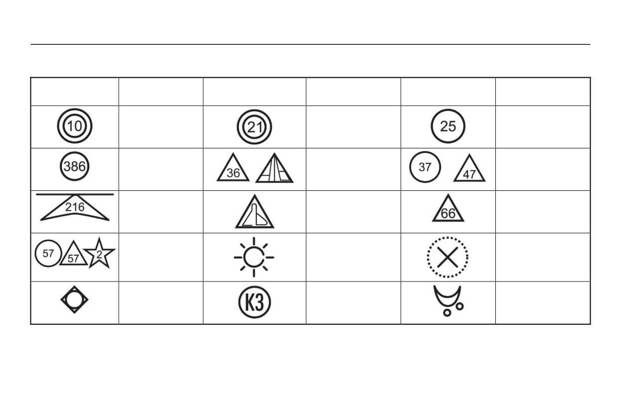
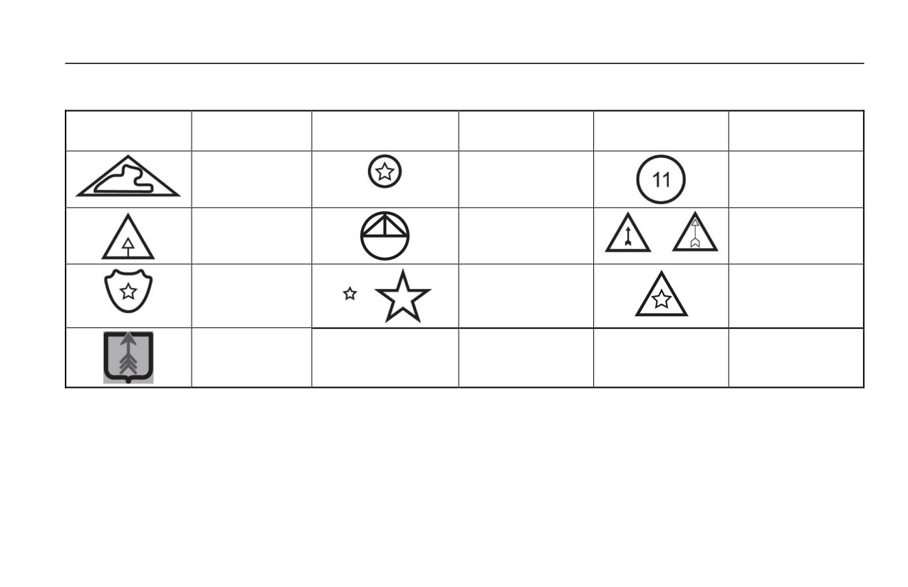
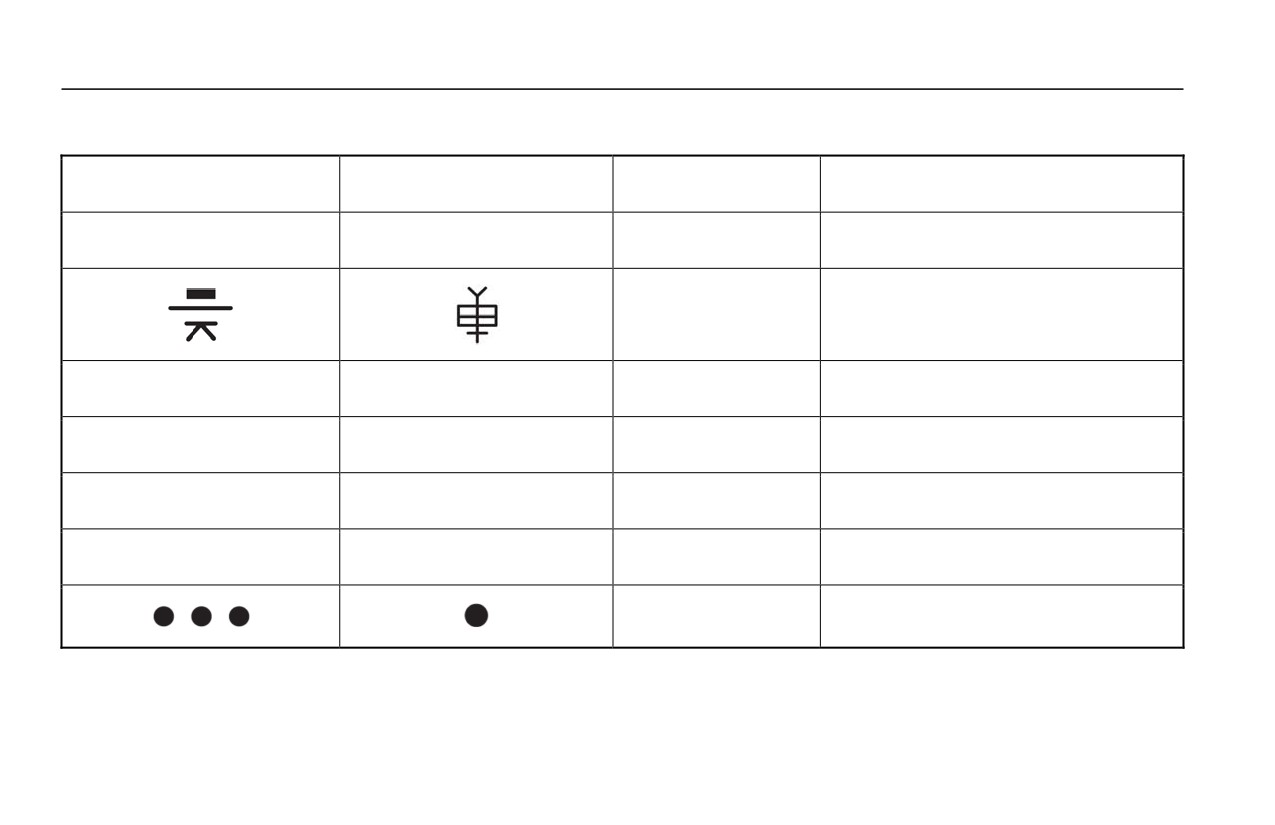
The AK-47 rifle can have a fixed or threaded muzzle and it can have a fixed or folding buttstock. The handguards and
fixed buttstock can be made of wood, metal, or plastic. The lower handguard may include a fore grip. The country of
origin can be identified by the manufacturer’s markings or selector lever setting markings on the right side of the receiver.
Refer to Tables 2 and 3.
EQUIPMENT CHARACTERISTICS, CAPABILITIES, AND FEATURES
Table 1 contains the characteristics, capabilities, and features of the AK-47 rifle. Table 2 contains manufacturer markings
of the AK-47. Table 3 contains selector lever setting markings for manufacturers of the AK-47.
0002 00-4

TM 8370-50007-OR/1
0002 00
Table 1. AK-47 Characteristics.
AK-47
Caliber
7.62 x 39 mm
Weight (Empty)
Approx. 9.48 lbs
Length:
Fixed Buttstock/Folding Buttstock-Extended
Approx. 34.2 inches
Folding Buttstock-Folded
Approx. 27.5 inches
Rifling
4 grooves, right-hand twist
1 turn in 12 inches
Muzzle Velocity:
Approx. 2346 fps
Sustained Rate of Fire
12/15 rounds per minute
Maximum Effective Range
400 meters
Fire Selector
SAFE, AUTO, SEMI
Sights:
Front
Adjustable front sight post for elevation
Adjustable windage drum for windage
Rear
Adjustable leaf sight for elevation
Magazine Capacity
30 rounds
0002 00-5
TM 8370-50007-OR/1
0002 00
Table 2. Manufacturer’s Markings.
Marking
Producer
Marking
Producer
Marking
Producer
Bulgaria
Bulgaria
Bulgaria
China/PRC
China/PRC
China/PRC
(Polytec)
China/PRC
China/PRC
China/PRC
(Norinco)
China/PRC
E. Germany
East Germany
East Germany
East Germany
Egypt
(Suhl Factory)
(Ernst Thaelmann
Factory)
0002 00-6
TM 8370-50007-OR/1
0002 00
Table 2. Manufacturer’s Markings - Continued.
Marking
Producer
Marking
Producer
Marking
Producer
Iraq
North Korea
Poland
Romania
Russia
Russia (Izhevsk
Factory)
Russia (Polyany
Russia (Tula
Russia (Tula
Arsenal)
Arsenal)
Arsenal)
Russia (Izhevsk
Factory)
0002 00-7
TM 8370-50007-OR/1
0002 00
Table 3. Selector Lever Setting Markings.
Upper or AUTO Symbol
Lower or SEMI Symbol
Producer
Indigenous Name or Remarks
AB
EA
Bulgaria
AK-47 & AKM
China/PRC
Early production
L
D
China/PRC
Type 56 & 56-1
30
1
Czechoslovakia
M58
D
E
East Germany
May not have a cleaning rod.
D
E
Egypt
MISR
Finland
Rynnakokivaari (M60 & M62)
0002 00-8
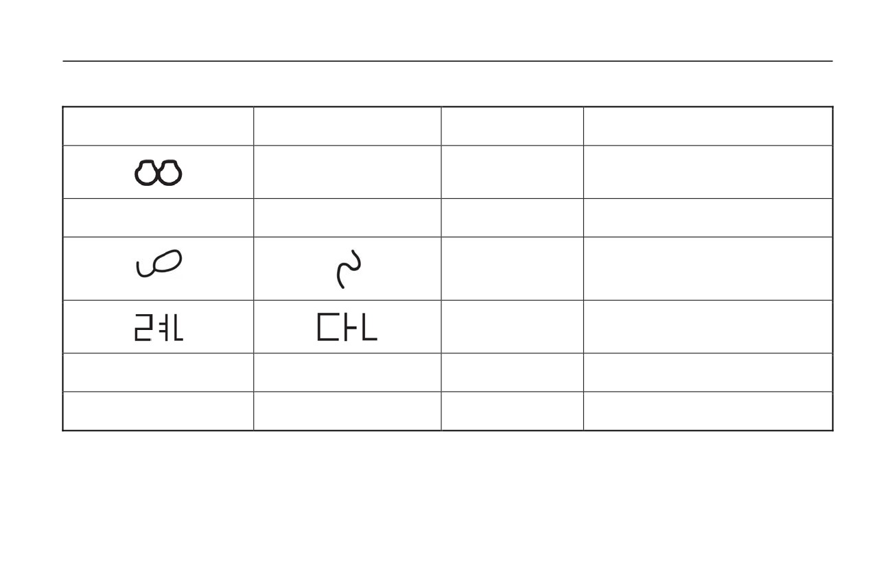
TM 8370-50007-OR/1
0002 00
Table 3. Selector Lever Setting Markings - Continued.
Upper or AUTO Symbol
Lower or SEMI Symbol
Producer
Indigenous Name or Remarks
1
Hungary
AKM-63 & AMD-65
L
D
Iran
KLS (AKM); KLF (AKMS)
Iraq
TABUK (AKM)
North Korea
Type 58 (AK-47) & Type 68 (AKM)
C
P
Poland
PMK, PMK-DGn & KbK AK
FA
FF
Romania
M63; “S” at top for SAFE position
0002 00-9

TM 8370-50007-OR/1
0002 00
Table 3. Selector Lever Setting Markings - Continued.
Upper or AUTO Symbol
Lower or SEMI Symbol
Producer
Indigenous Name or Remarks
AB or AV
OA or O
Russia
AK-47, AKS-47, AKM & AKMS
R
J
Yugoslavia
“U” at top for SAFE position
END OF WORK PACKAGE
0002 00-10

TM 8370-50007-OR/1
0003 00
PRINCIPLES OF OPERATION
SEMI-AUTOMATIC
1. Cycle of Operation. The cycle of operation is similar in all small arms. Knowledge of what happens during the cycle
of operation will help both the operator understand the cause of and remedy for various stoppages.
2. Eight Steps. The cycle of operation contains eight steps:
a. Feeding
b. Chambering
c. Locking
d. Firing
e. Unlocking
f.
Extracting
g. Ejecting
h. Cocking.
0003 00-1

TM 8370-50007-OR/1
0003 00
3. Description of Eight Steps. The eight steps of the cycle of operation are explained below. Assume that a full
magazine is loaded in the weapon.
a. Feeding. A magazine containing ammunition is inserted into the receiver. The magazine follower forces the top
cartridge into the path of the bolt. The magazine follower is under pressure from the magazine spring.
b. Chambering. Chambering occurs when a cartridge is driven into the chamber as the bolt goes forward under
pressure from the expanding action spring. The bolt picks up the top cartridge in the magazine and drives it
forward into the chamber. Chambering is complete when the extractor snaps into the extracting groove on the
cartridge.
c. Locking. Locking occurs when the bolt is fully closed. The closed bolt prevents the loss of gas pressure until the
bullet has left the muzzle. The bolt is rotated by the cam pin as the bolt carrier completes its forward motion,
locking the bolt into the barrel extension.
d. Firing. Firing occurs when the firing pin strikes the primer in the rear of the cartridge. When the trigger is pulled,
the trigger hooks disengage from the hammer and the hammer is released. The hammer moves forward under
pressure from the hammer spring and strikes the tang of the firing pin. This drives the firing pin against the
primer, which in turn ignites the propellant in the cartridge case and propels the bullet through the barrel into its
trajectory.
0003 00-2

TM 8370-50007-OR/1
0003 00
e. Unlocking. Unlocking occurs after a cartridge is fired. As the bullet is forced through the barrel by expanding
gases, a small amount of gas enters the gas tube and pushes the gas piston, and the rest of the bolt carrier
assembly and bolt assembly, to the rear. Excessive gas is vented through the ports in the gas tube. As the bolt
carrier moves rearward, the bolt rotates in the bolt carrier and unlocks from the barrel extension. Any remaining
gas follows the bullet out of the muzzle.
f.
Extracting. As the bolt moves to the rear, the bolt extractor holds the base of the cartridge against the bolt face.
Extraction is completed when the front of the cartridge case clears the rear of the chamber.
g. Ejecting. As the bolt moves to rear, the empty cartridge case is held by the extractor. The base of the cartridge
strikes the fixed ejector in the receiver. The extractor serves as a pivot point for the cartridge, which is then
deflected out of the ejection opening of the receiver.
h. Cocking. As the bolt moves to the rear, the bottom portion of the bolt carrier rides over the hammer, pushing the
hammer down and to the rear until it is caught by the disconnector, if the trigger is still held to the rear, or by the
trigger hook(s), if the trigger is released.
AUTOMATIC
1. Cycle of Operation. The cycle of operation is similar to semi-automatic operation, with some minor differences in
operation due to differences in internal fire control components.
2. Eight Steps. The automatic cycle of operation contains the same fundamental eight steps as the semi-automatic.
0003 00-3

TM 8370-50007-OR/1
0003 00
3. Description. With the selector lever in the AUTO position, the weapon will fire repeatedly as long as the trigger is
held or until the magazine empties. This is accomplished through the use of an auto sear that momentarily holds the
hammer rearward until the bolt has fed, chambered, and locked on the next round.
a. The trigger is pulled and held, releasing the hammer, which fires the first round.
b. As the bolt carrier moves rearward, the hammer is forced to the rear and is caught by the auto sear.
c. As the bolt carrier returns to the locked position, the auto sear releases the hammer and the next round is fired.
d. The sequence repeats as long as the trigger is held rearward or the magazine empties.
e. The cycle of operation will stop when the trigger is released and the hammer is caught by the trigger hooks.
END OF WORK PACKAGE
0003 00-4

TM 8370-50007-OR/1
CHAPTER 2
OPERATING INSTRUCTIONS