ORGANIZATIONAL MAINTENANCE MANUAL WITH REPAIR PARTS LIST FOR RIFLE, 7.62 MM, AK-47 (2009) - page 1

TM 8370-50007-IN/2
U.S. MARINE CORPS TECHNICAL MANUAL
ORGANIZATIONAL MAINTENANCE
MANUAL WITH REPAIR PARTS LIST
FOR
RIFLE, 7.62 MM, AK-47
NSN: 1005-LL-MUS-2940
P/N TBD
MARINE CORPS SYSTEMS COMMAND
QUANTICO, VA 22134-6050
DISTRIBUTION STATEMENT C: DISTRIBUTION AUTHORIZED TO U.S.
GOVERNMENT AGENCIES AND THEIR CONTRACTORS. THIS PUBLICATION IS
REQUIRED FOR ADMINISTRATION AND OPERATION PURPOSES. OTHER
REQUESTS FOR THIS DOCUMENT MUST BE REFERRED TO COMMANDER,
MARINE CORPS SYSTEMS COMMAND (PG-13, PM, IW), QUANTICO, VA 22134-6050.
DESTRUCTION NOTICE: DESTROY BY ANY METHOD THAT WILL PREVENT
DISCLOSURE OF CONTENTS OR RECONSTRUCTION OF THE DOCUMENTS.
FOR OFFICIAL USE ONLY
DECEMBER 2009
PCN 184 837001 00

DEPARTMENT OF THE NAVY
Headquarters, U.S. Marine Corps
Washington, DC 20380-0001
31 December 2009
1. This Technical Manual (TM), authenticated for Marine Corps use and effective upon receipt, provides
information on the Rifle, 7.62 mm, AK-47, NSN: 1005-LL-MUS-2940; TM 8370-50007-IN/2.
2. Submit notice of discrepancies or suggested changes on a NAVMC 10772. The NAVMC may be
submitted via the Internet using website https://pubs.ala.usmc.mil/front.htm, scrolling down to the NAVMC
10772 Tracking Program and following instructions provided. It may also be submitted by electronic mail to
mbmatcommarcorlogbases@logcom.usmc.mil, or by mailing a paper copy of NAVMC 10772 addressed to:
Commanding General, Marine Corps Systems Command, Attn: Assistant Commander Acquisition and
Logistics (LOG/TP), 814 Radford Blvd., Suite 20343, Albany, Georgia 31704-0343.
BY DIRECTION OF THE COMMANDANT OF THE MARINE CORPS
OFFICIAL:
MARK T. BRINKMAN
Program Manager, IW, PG-13
Marine Corps Systems Command
Quantico, Virginia
DISTRIBUTION: EDO

LIST OF EFFECTIVE PAGES/WORK PACKAGES
Date of issue for original manual is: 31 December 2009.
TOTAL NUMBER OF PAGES FOR FRONT AND REAR MATTER IS 18 AND TOTAL
NUMBER OF WORK PACKAGES IS 27 CONSISTING OF THE FOLLOWING:
Page/WP No.
Change No.
Page/WP No.
Change No.
Page/WP No.
Change No.
Front Cover
0
A through B
0
a through f
0
i through iv
0
Chp 1 Title Page
0
WP
0001 00 (2 pgs.)
0
WP
0002 00 (4 pgs.)
0
WP
0003 00 (2 pgs.)
0
Chp 2 Title Page
0
WP
0004 00 (2 pgs.)
0
WP
0005 00 (2 pgs.)
0
WP
0006 00 (14 pgs.)
0
Chp 3 Title Page
0
WP
0007 00 (2 pgs.)
0
WP
0008 00 (14 pgs.)
0
WP
0009 00 (4 pgs.)
0
WP
0010 00 (2 pgs.)
0
WP
0011 00 (4 pgs.)
0
WP
0012 00 (6 pgs.)
0
WP
0013 00 (28 pgs.)
0
WP
0014 00 (2 pgs.)
0
WP
0015 00 (4 pgs.)
0
WP
0016 00 (2 pgs)
0
WP
0017 00 (4 pgs.)
0
WP
0018 00 (2 pgs.)
0
WP
0019 00 (2 pgs.)
0
WP
0020 00 (2 pgs.)
0
WP
0021 00 (8 pgs.)
0
Chp 4 Title Page
0
WP
0022 00 (2 pgs.)
0
Chp 5 Title Page
0
WP
0023 00 (2 pgs.)
0
WP
0024 00 (2 pgs.)
0
WP
0025 00 (4 pgs.)
0
WP
0026 00 (4 pgs.)
0
WP
0027 00 (12 pgs.)
0
Index (2 pgs.)
0
A/B blank
TM 8370-50007-IN/2
WARNING SUMMARY
This warning summary contains safety warnings that must be understood and applied during operation and
maintenance of this equipment. Failure to observe these precautions could result in serious injury or death to
personnel.
WARNING
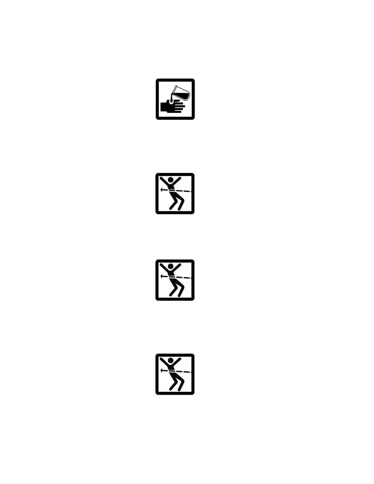
When using carbon removing compound, avoid skin contact. Using gloves
and protective equipment is required. If carbon removing compound comes
in contact with skin, wash thoroughly with running water. If possible, use a
lanolin-based cream after exposure to compound. Failure to follow these
warnings may cause injury or death to personnel.
WARNING
Ensure that the weapon is unloaded and that the selector lever is set on SAFE
before performing the following procedures. Do not keep live ammunition
near the work area. Failure to follow these warnings may cause injury or
death to personnel.
WARNING
Before starting an inspection, be sure to clear the weapon. Do not pull the
trigger until the weapon has been cleared. Inspect the chamber to ensure that
it is empty and no ammunition is in position to be chambered. DO NOT keep
live ammunition in the work area. Failure to follow these warnings may
cause injury or death to personnel.
WARNING
Ensure the weapon is clear prior to performing the following function
checks. If the weapon fails any of the following function checks, attempt to
repair it. If the weapon is beyond repair, replace it. Failure to follow these
warnings may cause injury or death to personnel.
a
TM 8370-50007-IN/2
WARNING
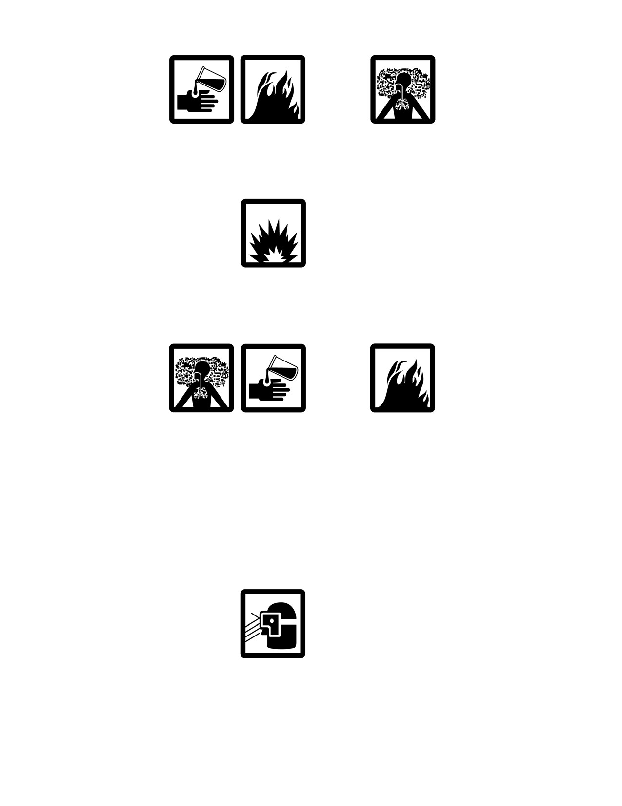
Dry cleaning solvent is flammable and toxic and should be used in a
well-ventilated area. The use of rubber gloves is necessary to protect the skin
when washing weapon parts. Failure to follow this warning may cause injury
or death to personnel.
WARNING
During general maintenance, DO NOT interchange bolt assemblies from one
weapon to another without checking for the proper headspace. Refer to WP
0021 00. Failure to follow this warning may cause injury or death to
personnel.
WARNING
Use only cleaner, lubricant, and preservative
(CLP) for cleaning and
lubrication of the AK-47 rifle in all but the most severe conditions.
Improper cleaning methods and use of unauthorized cleaning solvents may
injure personnel and damage equipment. Refer to TM 9-247_, Materials
Used for Cleaning, Preserving, Abrading, and Cementing Ordnance
Materials and Related Materials Including Chemicals for correct
information.
Cloths or rags saturated with solvent cleaning compound must be disposed of
in accordance with authorized facilities’ procedures. Failure to follow these
warnings may result in injury or death to personnel.
WARNING
Eye shields must be worn when cleaning with a wire brush. Flying rust and
metal particles may cause injury to personnel.
b
TM 8370-50007-IN/2
WARNING
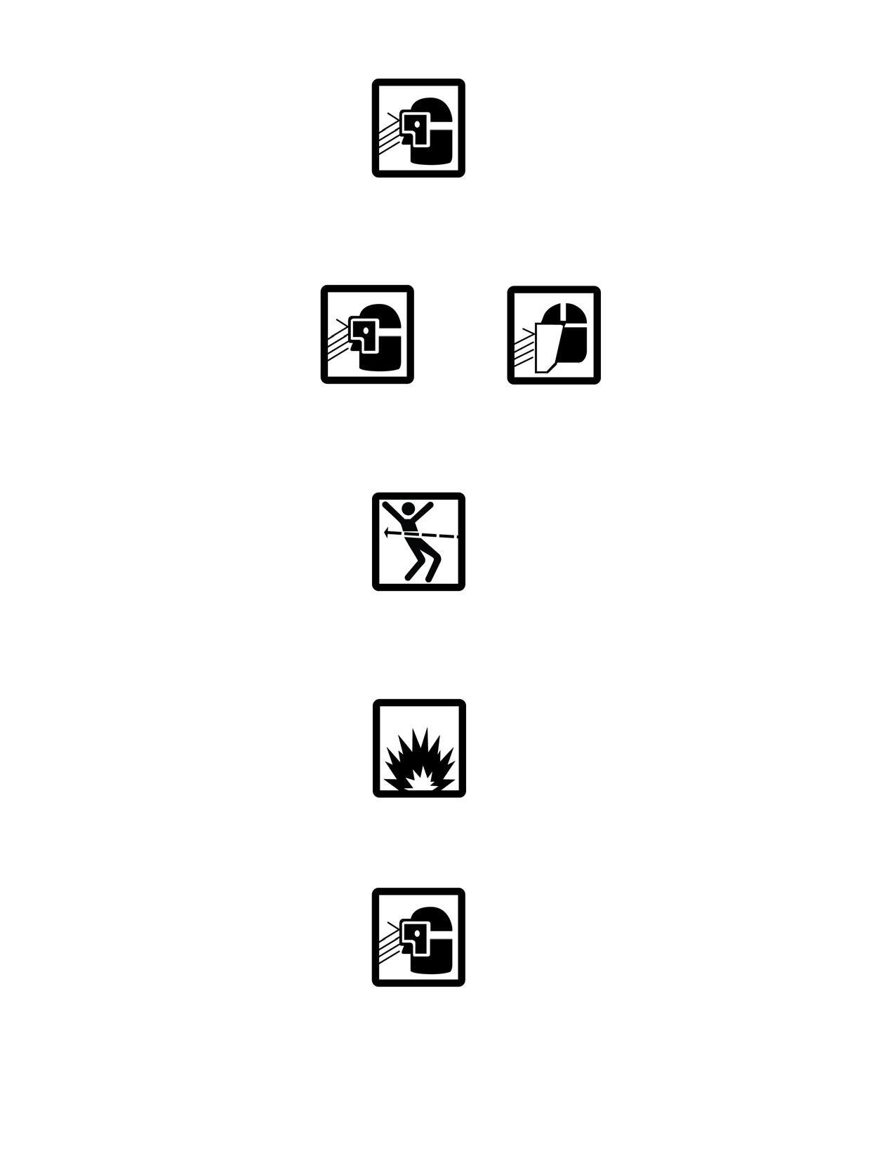
Particles blown by compressed air are hazardous. Use a maximum of 30 psi
when cleaning components. DO NOT exceed 15 psi nozzle pressure when
drying parts with compressed air. Failure to follow these warnings may result
in injury or death to personnel.
WARNING
DO NOT direct compressed air against human skin. Make sure air stream is
directed away from the user and other personnel in the area. To prevent
injury, the user must wear protective goggles or a face shield. Failure to
follow these warnings may result in injury or death to personnel.
WARNING
Always assume that every weapon is loaded until it is determined through
visual and physical inspection that it is not. Procedures for clearing and
unloading the weapon are outlined in TM 8370-50007-OR/1. Failure to
follow this warning may cause injury or death to personnel.
WARNING
DO NOT interchange bolt assemblies from one weapon to another without
checking for the proper headspace. Failure to follow this warning may cause
injury or death to personnel.
WARNING
The grooved extractor retaining pin and extractor are under spring tension.
c
TM 8370-50007-IN/2
WARNING
If the bolt is replaced, perform head space gaging. Refer to WP 0021 00.
WARNING
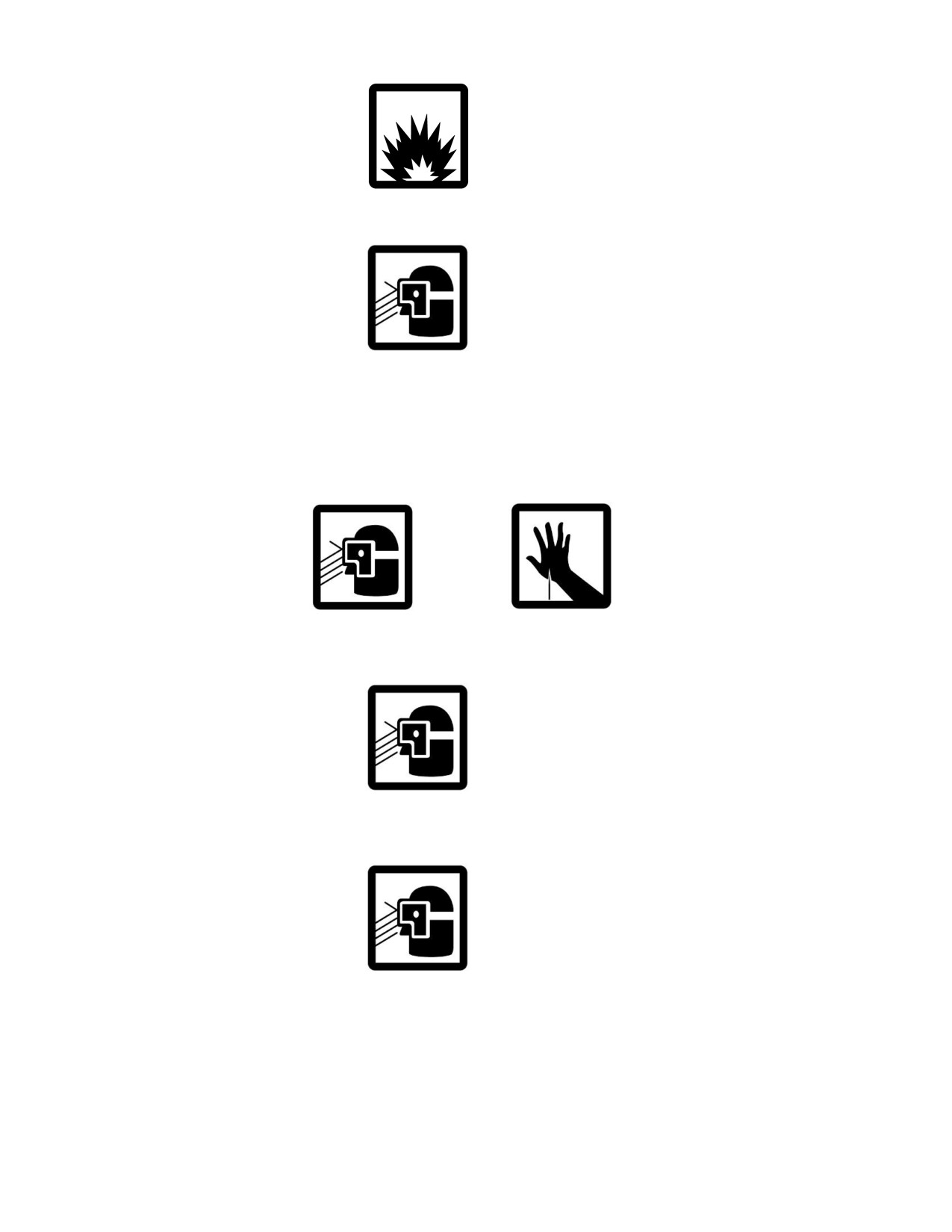
The auto sear is under spring tension. Use care when removing or installing
the auto sear.
After pushing down the lever of the auto sear, the hammer will be under
spring tension. Pulling the trigger will release the hammer and it will fall
forward with force.
WARNING
The hammer spring is under spring tension and the ends may be sharp
enough to puncture the skin.
WARNING
The elevation slide assembly is under spring tension. Use care when working
on spring-loaded parts.
WARNING
The buttplate and trapdoor are under spring tension. Use care when removing
the trap door and buttplate.
d
TM 8370-50007-IN/2
WARNING
The trap door is under spring tension. Use care when installing the trap door
and buttplate.
WARNING
Ensure the weapon is clear prior to performing the following function
checks. If the weapon fails any of the following function check, attempt to
repair it. If the weapon is beyond repair, replace it.
WARNING
Before stowing a weapon, be sure to clear the weapon
(TM-8370-50007-OR/1). Inspect the chamber to ensure it is empty and that
no ammunition is in position to be chambered. Failure to follow this warning
may cause injury or death to personnel.
WARNING
DO NOT store the weapon with live ammunition in either the chamber or
magazine. Always assume that every weapon is loaded until it is determined
through visual and physical inspection that it is not. Procedures for clearing
and unloading the weapon are outlined in TM 8370-50007-OR/1. Failure to
follow these warnings may cause injury or death to personnel.
WARNING
DO NOT keep live ammunition near the work area. Failure to follow this
warning may cause injury or death to personnel.
e

TM 8370-50007-IN/2
CAUTION SUMMARY
CAUTION
DO NOT use a wire brush to roughen the surfaces. Use a well-ventilated area
during cleaning and the application of solid film lubricant (SFL). If SFL
comes in contact with moving parts or functioning surfaces of the weapon,
remove the SFL immediately by washing the area with dry cleaning solvent.
CAUTION
Do not mix multiple lubricants on the same weapon. The weapon must be
cleaned thoroughly when changing from one lubricant to another. Dry
cleaning solvent (SD) is recommended for removing the old lubricant before
changing to another lubricant.
CAUTION
Ensure the groove in the grooved extractor retaining pin is aligned with the
firing pin retaining pin hole BEFORE inserting the firing pin retaining pin.
Failure to do so may cause the firing pin retaining pin to lodge in the bolt
permanently.
CAUTION
Letting the hammer fall uncontrolled will damage the weapon. Ensure to
place a finger over the hammer before pulling the trigger in order to ride the
hammer forward.
CAUTION
Ensure that all retaining pins are fully seated in the receiver and that the long
leg of the auto sear is properly installed into the retaining grooves in the
heads of the retaining pins.
CAUTION
The C-clip can break and deform during installation. If the C-clip becomes
bent or deformed, it should be replaced. Ensure that the open end of the
C-clip is facing towards the muzzle.
CAUTION
Letting the hammer fall uncontrolled will damage the weapon. Ensure to
place fingers over the hammer before pulling the trigger in order to ride the
hammer forward.
CAUTION
Only moderate pressure is necessary to remove the retaining pins from the
receiver. If the retaining pins are difficult to remove, check to ensure that the
grooves near the end of the retaining pins are not caught on the receiver wall.
CAUTION
When pushing the bolt closed during headspace gaging, be sure to use
LIGHT pressure. Failure to do so may damage the weapon.
f

TECHNICAL MANUAL
MARINE CORPS SYSTEMS COMMAND
TM 8370-50007-IN/2
Quantico, VA, DECEMBER 2009
U.S. MARINE CORPS TECHNICAL MANUAL
ORGANIZATIONAL MAINTENANCE MANUAL
WITH REPAIR PARTS LIST
FOR
RIFLE, 7.62 MM, AK-47
NSN: 1005-LL-MUS-2940
P/N TBD
DISTRIBUTION STATEMENT C: DISTRIBUTION AUTHORIZED TO U.S. GOVERNMENT AGENCIES
AND THEIR CONTRACTORS. THIS PUBLICATION IS REQUIRED FOR ADMINISTRATION AND
OPERATION PURPOSES. OTHER REQUESTS FOR THIS DOCUMENT MUST BE REFERRED TO
COMMANDER, MARINE CORPS SYSTEMS COMMAND (PG-13, PM, IW), QUANTICO, VA 22134-6050.
DESTRUCTION NOTICE: DESTROY BY ANY METHOD THAT WILL PREVENT DISCLOSURE OF
CONTENTS OR RECONSTRUCTION OF THE DOCUMENTS.
WP/Page Number
List of Effective Pages/Work Packages
A
Warning Summary
a
Caution Summary
f
How to Use This Manual
iii
CHAPTER 1 - GENERAL INFORMATION, EQUIPMENT DESCRIPTION AND DATA, AND
PRINCIPLES OF OPERATION
General Information
0001 00-1
Equipment Description and Data
0002 00-1
Principles of Operation
0003 00-1
CHAPTER 2 - TROUBLESHOOTING
Troubleshooting Introduction
0004 00-1
Troubleshooting Symptom Index
0005 00-1
Troubleshooting Procedures
0006 00-1
CHAPTER 3 - ORGANIZATIONAL MAINTENANCE
Service Upon Receipt
0007 00-1
Preventive Maintenance Checks and Services (PMCS), Including Lubrication Instructions
0008 00-1
General Maintenance Instructions
0009 00-1
Disassembly of Weapon
0010 00-1
Bolt Carrier Assembly and Bolt Assembly
0011 00-1
Bolt Assembly
0012 00-1
Receiver Assembly
0013 00-1
Rear Sight Assembly
0014 00-1
Fixed Buttstock Assembly
0015 00-1
Reassembly of Weapon
0016 00-1
Function Check
0017 00-1
Stowage
0018 00-1
Preparation for Storage and Shipment
0019 00-1
Final Inspection and Function Test
0020 00-1
Gaging Procedures
0021 00-1
i

TM 8370-50007-IN/2
Table of Contents - Continued
WP / Page Number
CHAPTER 4 - AUXILIARY EQUIPMENT
Auxiliary Equipment - General
0022 00-1
CHAPTER 5 - SUPPORTING INFORMATION
References
0023 00-1
Expendable and Durable Items List
0024 00-1
Tool Identification List (Includes Special Tools)
0025 00-1
Repair Parts List (RPL) Introduction
0026 00-1
Repair Parts List (RPL)
0027 00-1
Index
Index-1
ii

TM 8370-50007-IN/2
HOW TO USE THIS MANUAL
INTRODUCTION
1. This manual contains operating instructions, maintenance procedures, and troubleshooting procedures for
the rifle, 7.62 mm, AK-47. It is divided into five chapters.
2. This manual is written in work package format:
a. Chapters divide the manual into major categories of information (e.g.., General Information,
Equipment Description and Data, and Principles of Operation).
b. Each chapter is divided into work packages, which are identified by a 6-digit number (e.g., 0001 00,
0002 00) located at the upper right-hand corner of each page. The work package page number (e.g.,
0001 00-1, 0001 00-2) is centered at the bottom of each page.
c. If a change package is issued to this manual, added work packages will use the 5th and 6th digits of
their numbers to indicate new material. For instance, work packages inserted between WP 0001 00
and WP 0002 00 are numbered WP 0001 01, WP 0001 02.
3. This manual should be read from beginning to end to become familiar with its organization and contents
before you attempt to operate or maintain the equipment.
CONTENTS OF THIS MANUAL
1.
A Warning Summary and a Caution Summary are located at the beginning of this manual. Become
familiar with these warnings and cautions before operating or maintaining the equipment.
2.
A Table of Contents, located in the front of this manual, lists all chapters and work packages in the
publication. If you cannot find what you are looking for in the Table of Contents, refer to the alphabetical
Index at the back of the manual.
3.
Chapter 1, General Information, Equipment Description and Data, and Principles of Operation, provides
general information about the equipment, identifies the major components and systems, and describes
how the components and systems work.
4.
Chapter 2, Troubleshooting, provides symptoms and procedures pertaining to failures that could occur
during operation of the AK-47.
5.
Chapter 3, Organizational Maintenance, which includes Preventive Maintenance Checks and Services
(PMCS), and General Maintenance Instructions, provide procedures to maintain the AK-47 at the
organizational level.
6.
Chapter 4, Auxiliary Equipment, which includes information on the equipment used with the AK-47 rifle.
7.
Chapter 5, Supporting Information, provides information pertaining to references, components listing, and
an expendable and durable items list.
8.
An alphabetical Index is located at the back of this manual.
iii

TM 8370-50007-IN/2
FEATURES OF THIS MANUAL
1.
This manual contains information on operating and maintaining the AK-47.
2.
WARNINGs, CAUTIONs, NOTEs, subject headings, and other important information are highlighted in
BOLD print as a visual aid.
WARNING
A WARNING indicates a hazard which may result in injury or death to
personnel.
CAUTION
A CAUTION is a reminder of safety practices or directs attention to usage
practices that may result in damage to equipment.
NOTE
A NOTE is a statement containing information that will make the procedures
easier to perform.
3.
Statements and words of particular interest may be printed in CAPITAL LETTERS to create emphasis.
4.
Within a procedural step, reference may be made to another chapter or work package in this manual or to
another manual. These references indicate where you should look for more complete information. If you
are told: “Attach the bore brush to the end of the flexible rod (WP 0014 00)”, go to WP 0014 00 in this
manual for instructions.
5.
Illustrations are placed after, and as close to, the procedural steps to which they apply. Callouts placed on
art are text or numbers.
END OF WORK PACKAGE
iv

TM 8370-50007-IN/2
CHAPTER 1
GENERAL INFORMATION, EQUIPMENT DESCRIPTION AND
DATA, AND PRINCIPLES OF OPERATION

INTENTIONALLY BLANK

TM 8370-50007-IN/2
0001 00
GENERAL INFORMATION
SCOPE
1. Type of Manual. Organizational Maintenance Manual for the AK-47 rifle. The basic operator’s
procedures are outlined in TM 8370-50007-OR/1, Operator’s Manual with Components List for Rifle,
7.62 mm, AK-47.
2. Equipment Name and Model Number. AK-47 rifle (NSN: 1005-LL-MUS-2940).
3. Purpose of Equipment. To provide personnel with the offensive and defensive capability to engage
targets with small arms fire.
MAINTENANCE FORMS, RECORDS, AND REPORTS
The Marine Corps forms and procedures used for equipment maintenance will be those prescribed by the
current edition of TM 4700-15/1_, Ground Equipment Record Procedures.
CORROSION PREVENTION AND CONTROL
Corrosion prevention on any piece of equipment is important and it is critically important for the safe
functioning of a weapons system. Carry out corrosion prevention and control (CPC) in accordance with
TM 4795-12/1_, Organizational Corrosion Prevention and Control Procedures for USMC Equipment.
While corrosion is typically associated with the rusting of metals, it can also include the deterioration of other
materials such as rubber, wood, and plastic. Unusual cracking, softening, swelling, or breaking of these
materials may be a corrosion problem.
DESTRUCTION INSTRUCTION TO PREVENT ENEMY USE
Follow the procedures in TM 750-244-7, Procedures for Destruction of Equipment, for the destruction of the
AK-47 rifle and its variants to prevent enemy use.
PREPARATION FOR STORAGE AND SHIPMENT
1. Follow the procedures outlined in MCO P4450.7, Preparation for Storage. Prior to storing or shipping,
ensure that the weapon is thoroughly cleaned as outlined in WP 0009 00.
2. Storage Procedures.
a. Ensure that the chamber and magazine are void of live ammunition.
b. Inspect the chamber and bore while applying a medium coat of cleaner, lubricant, and preservative
(CLP).
c. Apply a light coat of CLP over all the weapon’s metal surfaces to provide corrosion protection and
extra lubrication. Ensure that the CLP does not come into contact with any optical devices including
telescopic sight pieces.
QUALITY OF MATERIAL
All material used to repair, replace, or modify the weapon must meet the requirements of this manual. If the
quality of material requirements is not stated in this manual, the material must meet the requirements of the
drawings, standards, specifications, or approved engineering change proposals applicable to the subject
equipment.
0001 00-1

TM 8370-50007-IN/2
0001 00
SAFETY, CARE, AND HANDLING
Read the Warning Summary and Caution Summary at the front of this manual and pay close attention to the
warnings and cautions that appear where special care and attention are required. For ammunition care and
handling, refer to PAM 385-64, Ammunition and Explosives Safety Standards.
LIST OF ABBREVIATIONS/ACRONYMS
Abbreviation/Acronym
Definition
be
Bale
bk
Book
bt
Bottle
CAGEC
Commercial and Government Entity Code
CLP
Cleaner, Lubricant, and Preservative
CPC
Corrosion Prevention and Control
dz
Dozen
ea
Each
fps
Feet per Second
in
Inch
LAW
Lubricant, Arctic, Weapons
LSA
Lubricant, Semi-Fluid, Automatic Weapons
m
Meter
mL
Milliliter
mm
Millimeter
N/A
Not Applicable
NSN
National Stock Number
pkg
Package
PMCS
Preventive Maintenance Checks and Services
psi
Pounds per Square Inch
pt
Pint
rds/min
Rounds per Minute
ROD
Report of Discrepancy
RPL
Repair Parts List
SD
Dry Cleaning Solvent
SFL
Solid Film Lubricant
SMR
Source, Maintenance and Recoverability
SSRI
Supply System Responsibility Items
U/M
Unit of Measure
VCI
Volatile Corrosion Inhibitor
END OF WORK PACKAGE
0001 00-2
TM 8370-50007-IN/2
0002 00
EQUIPMENT DESCRIPTION AND DATA
DESCRIPTION
1. General. The AK-47 rifle is a 7.62 x 39 mm, lightweight, air-cooled, gas-operated, magazine-fed,
shoulder-fired weapon which can be selectively fired on the semi-automatic or full automatic settings.
2. Capabilities. Provides personnel the offensive and defensive capability to engage targets with direct
small arms fire.
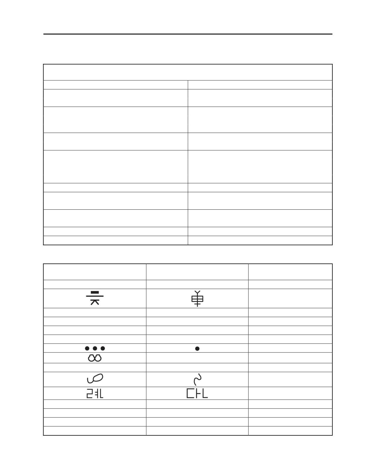
3. Differences Between Models. The AK-47 rifle can have a fixed or threaded muzzle and it can have a
fixed or folding buttstock. The handguards and buttstock can be made of wood, metal, or plastic. The
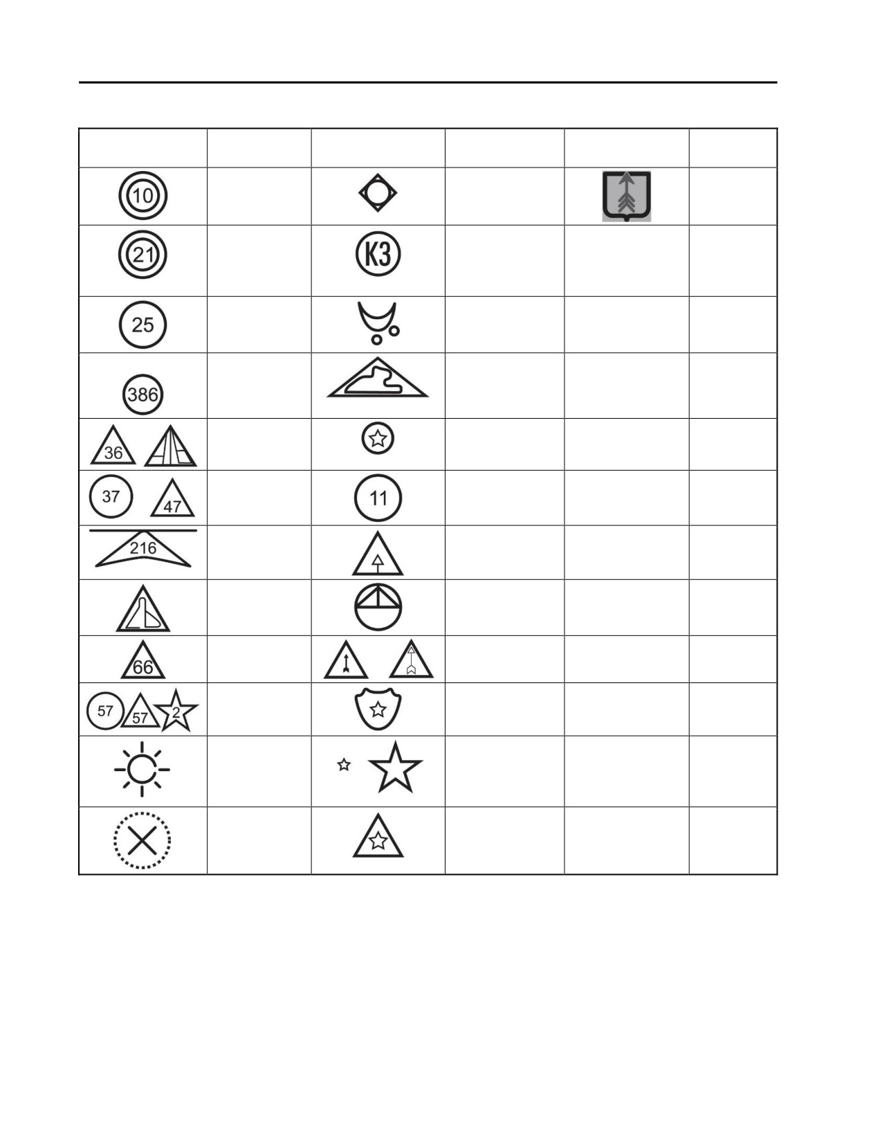
country of origin can be identified by the selector markings or manufacturer's markings on the right side
of the receiver. Refer to Tables 2 and 3.
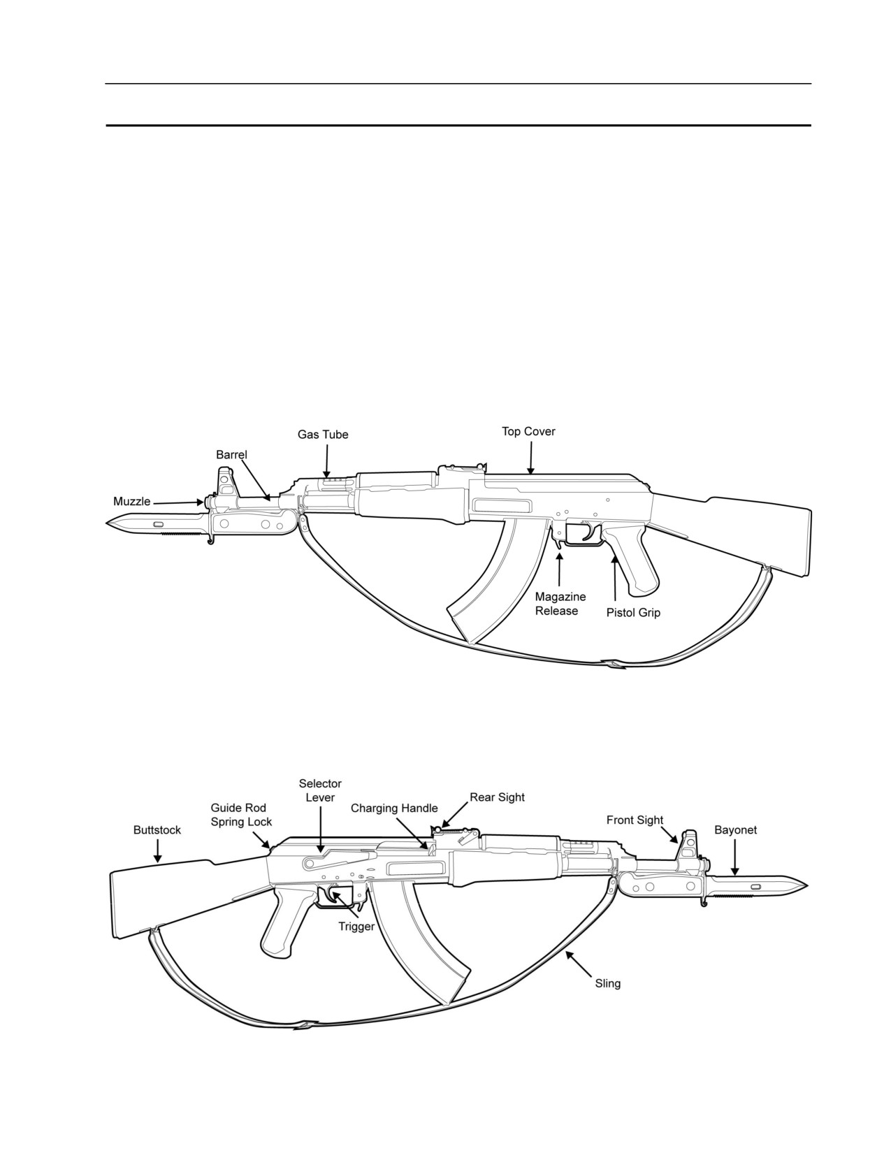
4. Left Side. The left side view of the weapon displays the muzzle, barrel, gas tube, top cover, magazine
release, and pistol grip. Refer to Figure 1.
Figure 1. Left Side of the AK-47 Rifle.
5. Right Side. The right side view of the weapon displays the buttstock, guide rod spring lock, trigger,
selector lever, charging handle, rear sight, front sight, sling, and bayonet. Refer to Figure 2.
Figure 2. Right Side of the AK-47 Rifle.
0002 00-1
TM 8370-50007-IN/2
0002 00
LOCATION AND DESCRIPTION OF MAJOR COMPONENTS
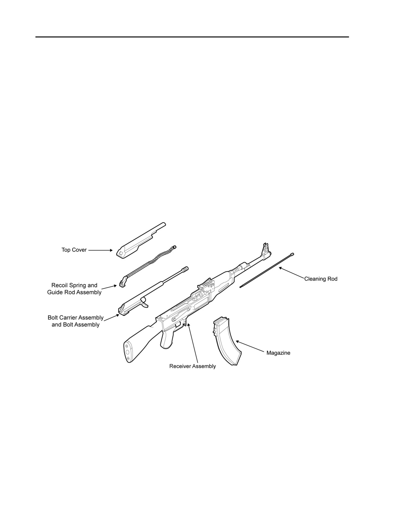
Refer to Figure 3.
1. Receiver and Barrel Assembly. The receiver and barrel assembly includes the front sight assembly, gas
block, gas tube, upper and lower handguards, rear sight assembly, auto sear, auto sear spring, hammer
assembly, magazine release, selector lever, trigger assembly, pistol grip, and buttstock.
2. Top Cover. The top cover covers and protects the mechanisms housed in the receiver.
3. Recoil Spring and Guide Rod Assembly. The recoil spring and guide rod assembly returns the bolt
carrier group to the locked position during the counter-recoil cycle.
4. Bolt Carrier Assembly and Bolt Assembly. The bolt carrier assembly includes the charging handle, gas
piston, bolt carrier, and houses the bolt assembly, which includes the bolt, grooved extractor retaining pin,
extractor, extractor spring, firing pin retaining pin, and firing pin. It carries out the cycle of operation.
5. Magazine. The magazine can be metal or plastic, can hold 30 rounds, and is attached to the receiver
through the magazine well. It is held in place by the magazine catch. The forward motion of the bolt
carrier assembly strips the cartridge from the magazine and feeds it into the chamber.
6. Cleaning Rod. The cleaning rod is used to conduct preventive maintenance.
Figure 3. The AK-47 Disassembled.
0002 00-2
TM 8370-50007-IN/2
0002 00
EQUIPMENT DATA
Table 1. AK-47 Rifle Equipment Data.
AK-47 Rifle Equipment Data
Caliber:
7.62 x 39 mm
Total Weight:
Weapon (empty)
Approx. 9.48 lbs.
Length:
Fixed Buttstock/Buttstock-Extended
Approx. 34.2 inches
Buttstock Folded
Approx. 27.5 inches
Rifling:
4 grooves, right-hand twist
1 turn in 12 inches
Sights:
Front
Adjustable sight post for elevation
Adjustable windage drum for windage
Rear
Leaf sight for elevation
Magazine Capacity:
30 rounds
Modes of Fire:
Semi-automatic
Fully automatic
Maximum Effective Range:
Semi-automatic
Approx. 400 m
Rate of Fire (cyclic):
Approx. 800 rds/min
Muzzle Velocity:
Approx. 2346 fps
Table 2. Selector Lever Markings.
Upper or Full Auto Symbol
Lower or Semi Auto Symbol
Producer
AB
EA
Bulgaria
China/PRC
L
D
China/PRC
30
1
Czechoslovakia
D
E
East Germany
D
E
Egypt
Finland
1
Hungary
L
D
Iran
Iraq
North Korea
C
P
Poland
FA
FF
Romania
AB or AV
OA or O
Russia
R
J
Yugoslavia
0002 00-3
TM 8370-50007-IN/2
0002 00
Table 3. Manufacturer’s Markings.
Marking
Producer
Marking
Producer
Marking
Producer
Bulgaria
East Germany
Russia
(Suhl Factory)
(Izhevsk
Factory)
Bulgaria
East Germany
(Ernst
Thaelmann
Factory)
Bulgaria
Egypt
China/PRC
Iraq
(Polytec)
China/PRC
North Korea
China/PRC
Poland
China/PRC
Romania
China/PRC
Russia
China/PRC
Russia (Izhevsk
(Norinco)
Factory)
China/PRC
Russia (Polyany
Arsenal)
East Germany
Russia (Tula
Arsenal)
East Germany
Russia (Tula
Arsenal)
END OF WORK PACKAGE
0002 00-4

TM 8370-50007-IN/2
0003 00
PRINCIPLES OF OPERATION
GENERAL
The 7.62 x 39 mm AK-47 rifle:
1. Is gas-operated.
2. Fires in either the semi-automatic (SEMI) or fully automatic (AUTO) mode.
3. Has positive locking of the bolt. The firing pin is part of the bolt assembly and cannot strike the primer
until the bolt assembly is fully locked.
CYCLE OF OPERATION
The cycle of operation is similar in all small arms. Knowledge of what happens during the cycle of operation
will help both the operator and the maintainer understand the cause of and remedy for various stoppages.
NOTE
The cycle of operation begins at any of the following eight steps.
1.
Eight Steps. The cycle of operation contains eight steps:
a. Feeding
b. Chambering
c. Locking
d. Firing
e. Unlocking
f.
Extracting
g. Ejecting
h. Cocking.
2.
Description of Eight Steps. The eight steps of the cycle of operation are explained below, along with a
brief description of what occurs inside the rifle during each step. Assume that a full magazine is loaded
into the weapon.
a. Feeding. The magazine follower, under spring tension, feeds the top cartridge into the path of the
bolt. As the bolt, held in the bolt carrier, is pushed forward by the recoil spring, the bottom of the bolt
passes over the lips of the magazine, strips the top cartridge from the magazine, and pushes it into the
chamber.
b. Chambering. Chambering is complete when the cartridge is fully seated in the chamber and the
extractor is engaged in the extraction groove at the base of the cartridge.
Dirt or debris inside the chamber, or bent, dented, or otherwise faulty ammunition can prevent a
cartridge from fully chambering or extracting.
0003 00-1

TM 8370-50007-IN/2
0003 00
c.
Locking. The face of the bolt strikes the rear extension of the barrel and its forward movement is
stopped. As the bolt carrier continues forward, the cam recess in the bolt carrier acts on the cam on
the bolt causing the bolt to rotate. As the bolt rotates, the locking lugs on the head of the bolt engage
the locking recesses in the receiver. Locking is then complete.
d.
Firing. When the trigger is pulled, the trigger hook(s) disengage from the hammer. The tension of the
hammer spring pushes the hammer to rotate up and forward until it strikes the rear of the firing pin.
The firing pin is pushed forward through the face of the bolt and strikes the primer of the round,
which ignites the propellant in the cartridge. The expanding gases resulting from this explosion propel
the bullet forward through the barrel.
e.
Unlocking. As the round passes through the barrel and past the gas block, some of the gas (under
high pressure) expands into the gas tube. This gas pushes the gas piston, which is attached to the bolt
carrier, to the rear. As the bolt carrier is pushed to the rear, the cam recess in the bolt carrier acts on
the cam on the bolt, causing the bolt to rotate. As the bolt rotates, the locking lugs on the head of the
bolt disengage from the locking recesses in the receiver. Unlocking is then complete.
f.
Extracting. The bolt carrier, holding the bolt, continues to move to the rear under pressure from the
expanding gas. As the bolt moves to the rear, the bolt extractor holds the base of the cartridge against
the bolt face. Extraction is complete when the front of the empty cartridge case clears the rear of the
chamber.
g.
Ejecting. As the bolt moves to the rear, the empty cartridge case is held by the extractor. The base of
the cartridge strikes the fixed ejector located on the interior of the receiver. The extractor serves as a
pivot point for the cartridge, which is deflected out of the ejection opening of the receiver.
a.
Cocking. As the bolt moves to the rear, the bottom of the bolt carrier rides over the hammer. This
forces the hammer to rotate down and to the rear until it is engaged by the disconnector (if firing on
SEMI) or auto sear (if firing on AUTO). When the trigger is released, the trigger hooks engage the
hammer, holding it down and to the rear.
END OF WORK PACKAGE
0003 00-2

TM 8370-50007-IN/2
CHAPTER 2
TROUBLESHOOTING

INTENTIONALLY BLANK

TM 8370-50007-IN/2
0004 00
TROUBLESHOOTING INTRODUCTION
GENERAL
This section contains troubleshooting information for locating and correcting malfunctions that may occur
with the AK-47 rifle.
The Troubleshooting Symptom Index (WP 0005 00) is a quick reference aid in troubleshooting the weapon.
Table 1 in Troubleshooting Procedures (WP 0006 00) lists possible malfunctions, tests, or inspections, and
corrective actions taken for troubleshooting the AK-47 rifle at the organizational level. Perform the tests,
inspections, and corrective actions in the order shown in the table, except when the malfunction and cause are
obvious. This manual cannot list all of the possible malfunctions, tests or inspections, and corrective actions
of the AK-47 rifle.
END OF WORK PACKAGE
0004 00-1/2 blank

INTENTIONALLY BLANK

TM 8370-50007-IN/2
0005 00
TROUBLESHOOTING SYMPTOM INDEX
INTRODUCTION
Refer to Table 1 in Troubleshooting Procedures (WP 0006 00) for malfunctions, tests or inspections, and
corrective actions. The symptom index below is a quick reference of the malfunctions that are covered in the
table.
Malfunction/Symptom
Troubleshooting Procedure Page
1. Failure of Magazine to Lock in Weapon
0006 00-1
2. Failure to Feed
0006 00-2
3. Failure to Chamber
0006 00-2
4. Failure to Lock
0006 00-3
5. Failure to Fire
0006 00-6
6. Failure to Unlock
0006 00-7
7. Failure to Extract
0006 00-8
8. Failure to Eject
0006 00-8
9. Failure to Cock
0006 00-9
10. Short Recoil
0006 00-10
11. Rifle Cannot be Zeroed
0006 00-11
12. Failure to Cycle with Selector Lever on AUTO
0006 00-12
13. Weapon Fires with Selector Lever on SAFE or when Trigger is Released with
Selector Lever on SEMI
0006 00-12
14. Auto Sear Pin “Walks”
0006 00-13
15. Hammer Pin “Walks”
0006 00-13
16. Trigger Pin “Walks”
0006 00-14
17. Runaway Gun
0006 00-14
END OF WORK PACKAGE
0005 00-1/2 blank

INTENTIONALLY BLANK
TM 8370-50007-IN/2
0006 00
TROUBLESHOOTING PROCEDURES
GENERAL
Table 1 lists possible malfunctions, tests or inspections, and corrective actions to be taken for troubleshooting
the AK-47 rifle. All malfunctions are at the organizational level.
Table 1. Troubleshooting Procedures.
Malfunction
Test or Inspection
Corrective Action
1. Failure of magazine to lock
a. Defective magazine.
Replace the magazine.
in the weapon.
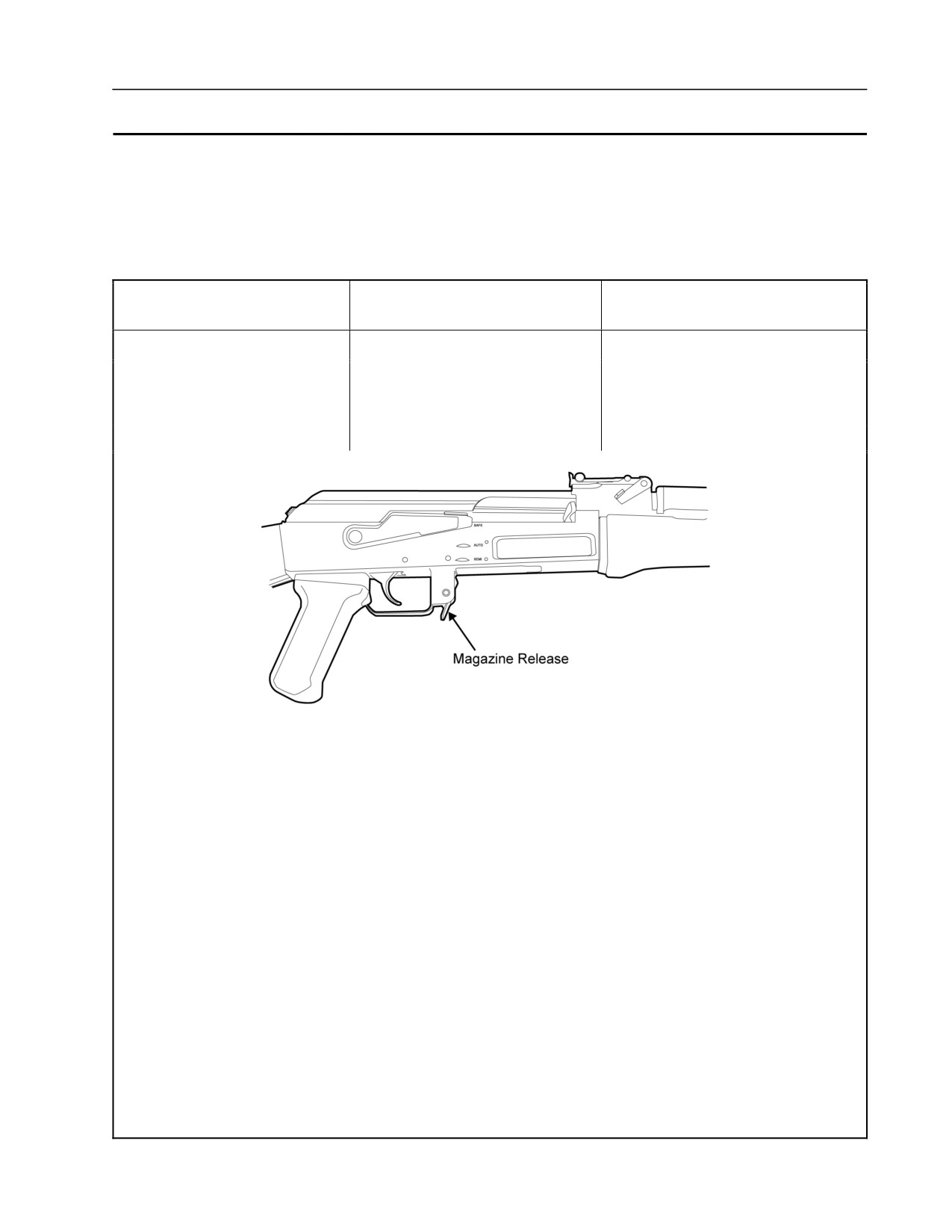
b. Magazine release is dirty,
Clean the magazine release. Attempt
corroded, or has no spring
to repair the magazine release or
tension. Refer to Figure 1.
replace the weapon.
c. Bent magazine well.
Replace the weapon.
Figure 1. Magazine Release.
0006 00-1
TM 8370-50007-IN/2
0006 00
Table 1. Troubleshooting Procedures - Continued.
Malfunction
Test or Inspection
Corrective Action
2. Failure to feed.
a. Dirty or corroded magazine.
Disassemble and clean the
magazine. Refer to
TM 8370-50007-OR//1.
b. Short recoil.
Refer to Short Recoil in this table
(# 10).
3. Failure to chamber.
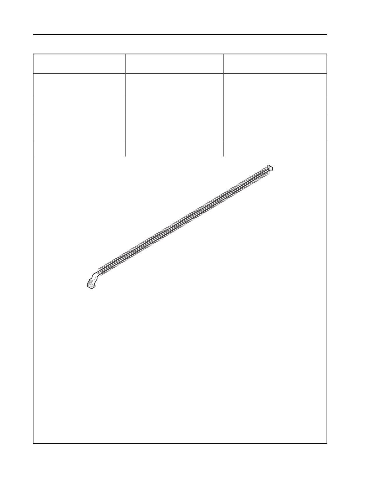
a. Weak, deformed, or broken
Replace the recoil spring and guide
recoil spring and guide rod
rod assembly. Refer to WP 0010 00.
assembly. Refer to Figure 2.
b. Short recoil.
Refer to Short Recoil in this table
(# 10).
Figure 2. Recoil Spring and Guide Rod Assembly.
0006 00-2
TM 8370-50007-IN/2
0006 00
Table 1. Troubleshooting Procedures - Continued.
Malfunction
Test or Inspection
Corrective Action
4. Failure to lock.
a. Chamber is dirty, burred, or
Clean the chamber. Remove any
has an obstruction.
burrs. Remove the obstruction.
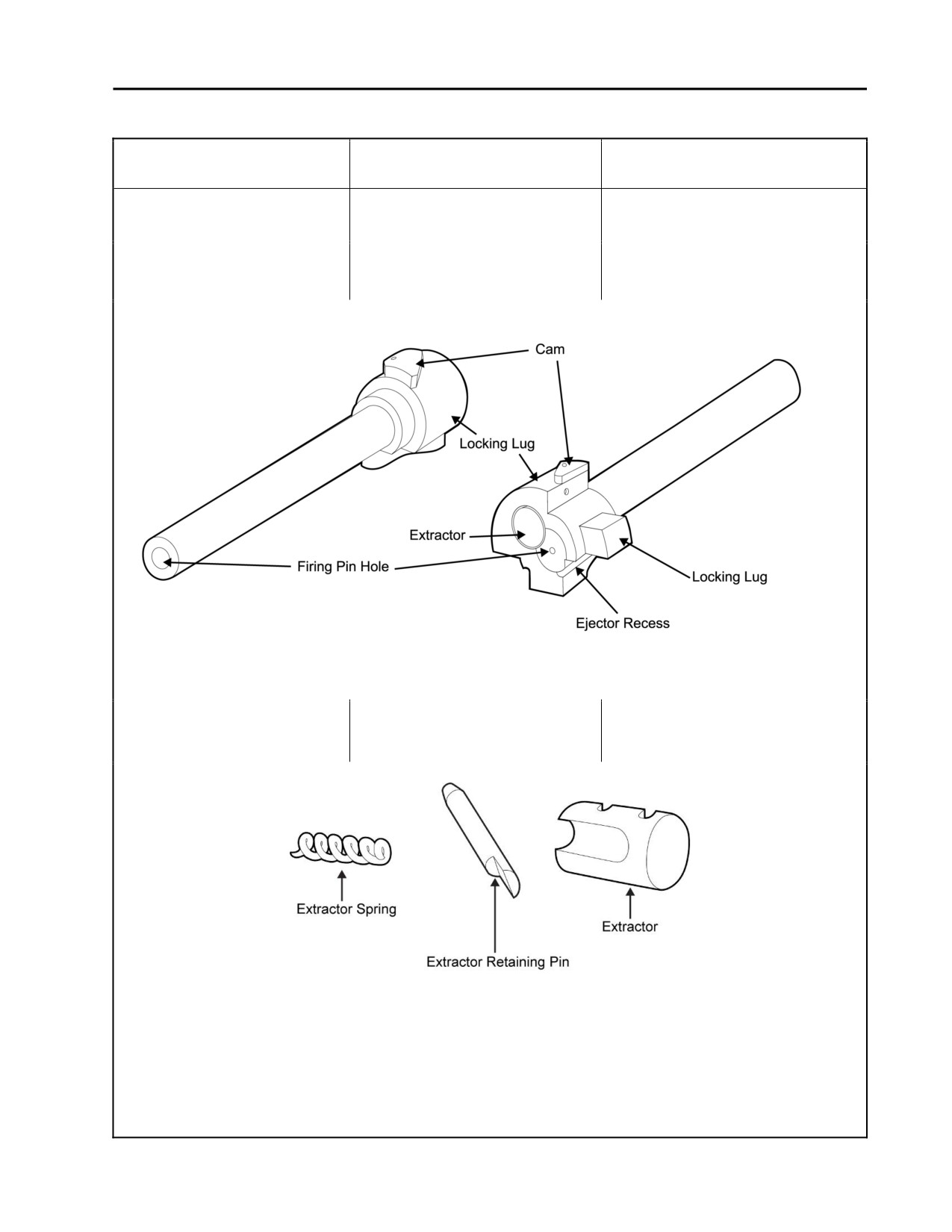
b. Burred, dirty, or damaged bolt.
Clean the bolt. Remove any burrs.
Refer to Figure 3.
Replace the bolt if necessary. Refer
to WP 0012 00.
Figure 3. Opposite Views of the Bolt.
c. Improperly assembled
Assemble the extractor assembly
extractor assembly. Refer to
correctly. Refer to WP 0012 00.
Figure 4.
Figure 4. Extractor Assembly.
0006 00-3
TM 8370-50007-IN/2
0006 00
Table 1. Troubleshooting Procedures - Continued.
Malfunction
Test or Inspection
Corrective Action
4. Failure to lock - Cont.
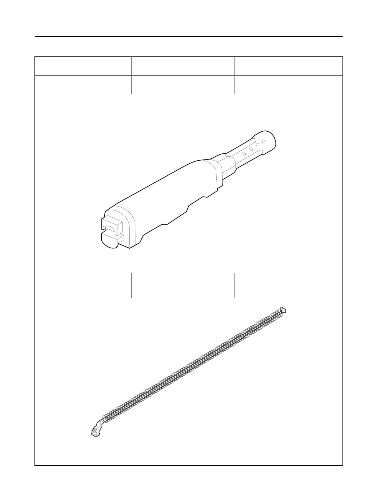
d. Defective gas tube. Refer to
Replace the gas tube. Refer to
Figure 5.
WP 0010 00.
NOTE
Pits or holes in the gas tube may be caused by ammunition which is
corrosive due to old age or poor manufacture.
Figure 5. Gas Tube in Handguard.
e. Weak or broken recoil spring
Replace the recoil spring and guide
and guide rod assembly.
rod assembly. Refer to WP 0010 00.
Refer to Figure 6.
Figure 6. Recoil Spring.
0006 00-4
TM 8370-50007-IN/2
0006 00
Table 1. Troubleshooting Procedures - Continued.
Malfunction
Test or Inspection
Corrective Action
4. Failure to lock - Cont.
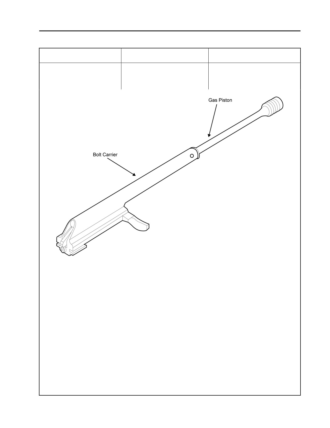
f.
Bolt carrier assembly (gas
Clean bolt carrier assembly. Remove
piston and bolt carrier) is dirty,
any burrs. Replace if necessary.
burred, or damaged Refer to
Refer to WP 0011 00.
Figure 7.
Figure 7. Bolt Carrier Assembly.
0006 00-5
TM 8370-50007-IN/2
0006 00
Table 1. Troubleshooting Procedures - Continued.
Malfunction
Test or Inspection
Corrective Action
5. Failure to fire.
a. Carbon buildup in bolt
Disassemble and clean the bolt
assembly.
assembly. Refer to WP 0012 00.
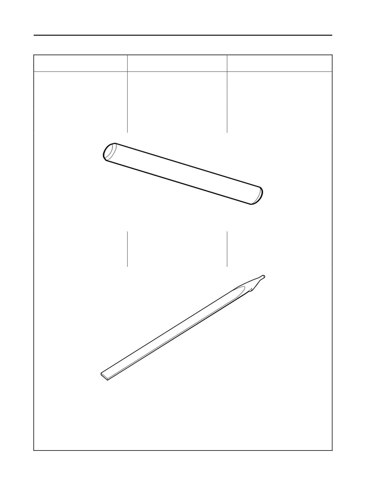
b. Firing pin retaining pin
Correctly install the firing pin
incorrectly installed.
retaining pin. Refer to WP 0012 00.
c. Broken, defective, or missing
Replace the firing pin retaining pin.
firing pin retaining pin. Refer
Refer to WP 0012 00.
to Figure 8.
Figure 8. Firing Pin Retaining Pin.
d. The firing pin is incorrectly
Correctly install the firing pin. Refer
installed.
to WP 0012 00.
e. Broken or chipped firing pin.
Replace the firing pin. Refer to
Refer to Figure 9.
WP 0012 00.
Figure 9. Firing Pin.
0006 00-6
TM 8370-50007-IN/2
0006 00
Table 1. Troubleshooting Procedures - Continued.
Malfunction
Test or Inspection
Corrective Action
5.
Failure to fire - Cont.
f.
Improperly assembled
Assemble the weapon correctly.
weapon.
Refer to TM 8370-50007-OR/1,
WP 0011 00, WP 0012 00, and
WP 0013 00.
g. Broken hammer or hammer
Replace the hammer or hammer
spring.
spring. Refer to WP 0013 00.
h. Hammer/trigger improperly
Assemble the hammer/trigger
assembled.
correctly. Refer to WP 0013 00.
i.
Hammer spring improperly
Install the hammer spring correctly.
installed.
Refer to WP 0013 00.
6.
Failure to unlock.
a. Burred bolt assembly.
Remove burrs or replace the bolt
assembly. Refer to WP 0012 00.
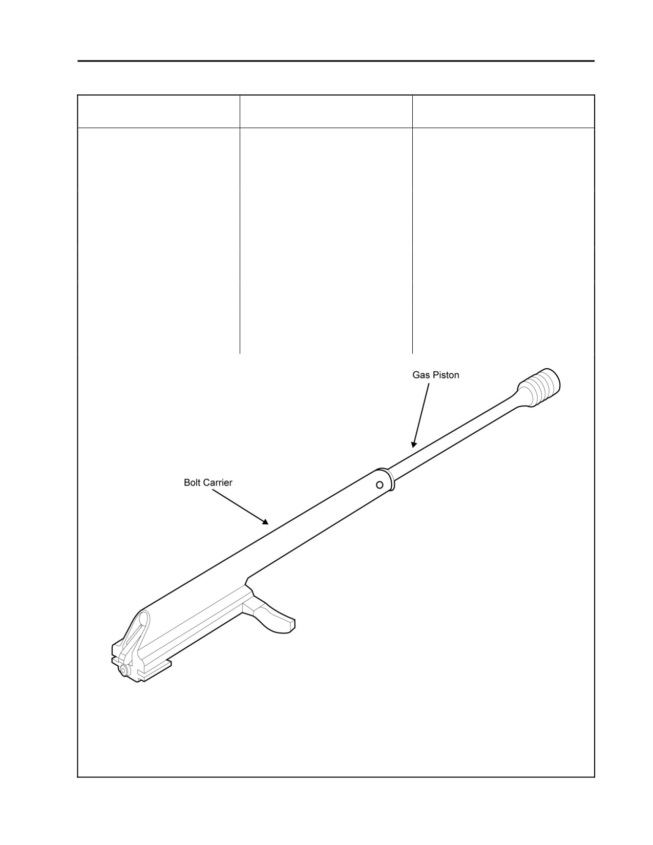
b. Burred bolt carrier assembly
Remove burrs or replace the bolt
(gas piston and bolt carrier).
carrier assembly. Refer to
Refer to Figure 10.
WP 0011 00.
Figure10. Bolt Carrier Assembly.
0006 00-7
TM 8370-50007-IN/2
0006 00
Table 1. Troubleshooting Procedures - Continued.
Malfunction
Test or Inspection
Corrective Action
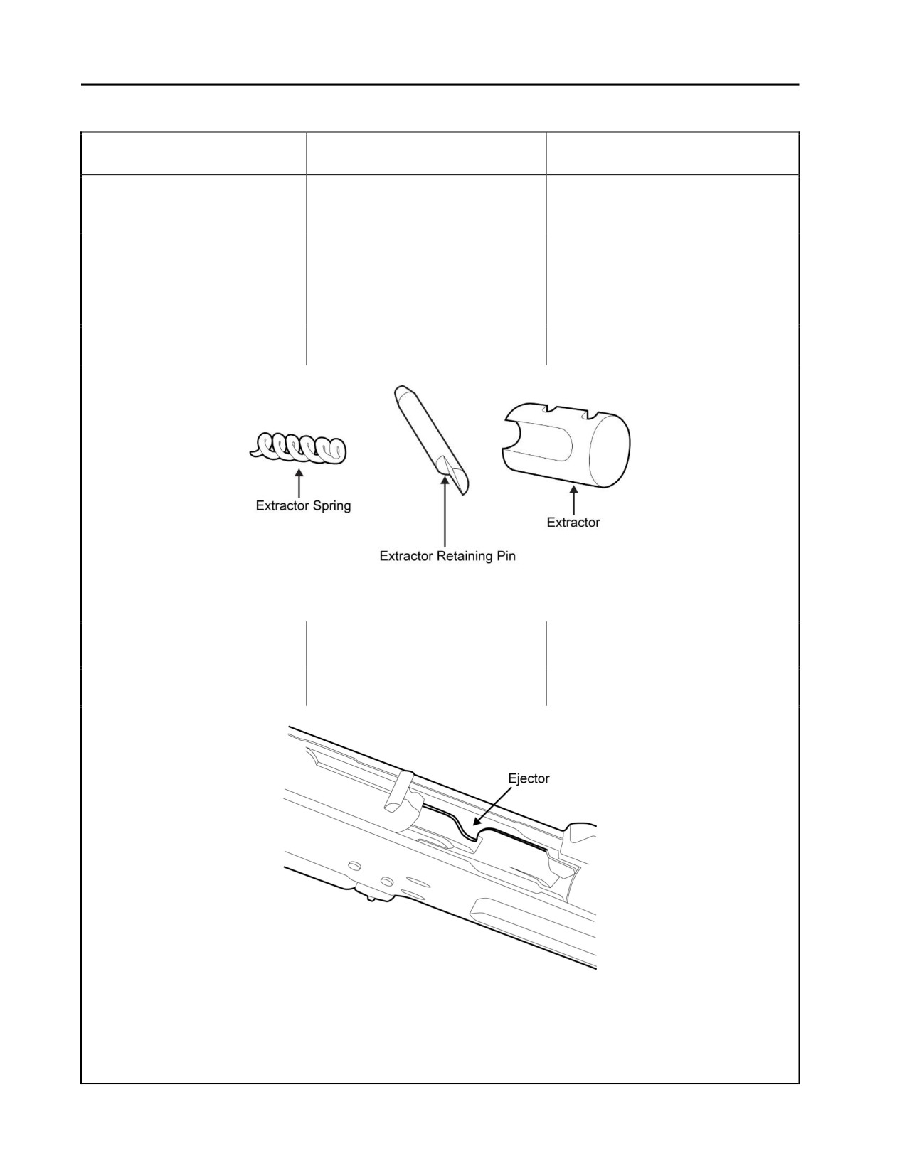
7. Failure to extract.
a. Defective extractor retaining
Replace the extractor retaining pin,
pin, extractor, and/or extractor
extractor, and/or extractor spring.
spring. Refer to Figure 11.
Refer to WP 0012 00.
b. A cartridge is lodged in the
Remove the cartridge. Check the
barrel due to bad ammunition
quality of ammunition. Gage the
or barrel erosion.
barrel to check for erosion. Replace
the weapon if necessary. Refer to
WP 0021 00
c. Short recoil.
Refer to Short Recoil in this table
(# 10).
Figure 11. Extractor Spring, Extractor Retaining Pin, and Extractor.
8. Failure to eject.
a. Defective cartridge ejector.
Attempt to repair. Replace the
Refer to Figure 12.
weapon if necessary.
b. Short recoil.
Refer to Short Recoil in this table
(# 10).
Figure 12. Ejector.
0006 00-8
TM 8370-50007-IN/2
0006 00
Table 1. Troubleshooting Procedures - Continued.
Malfunction
Test or Inspection
Corrective Action
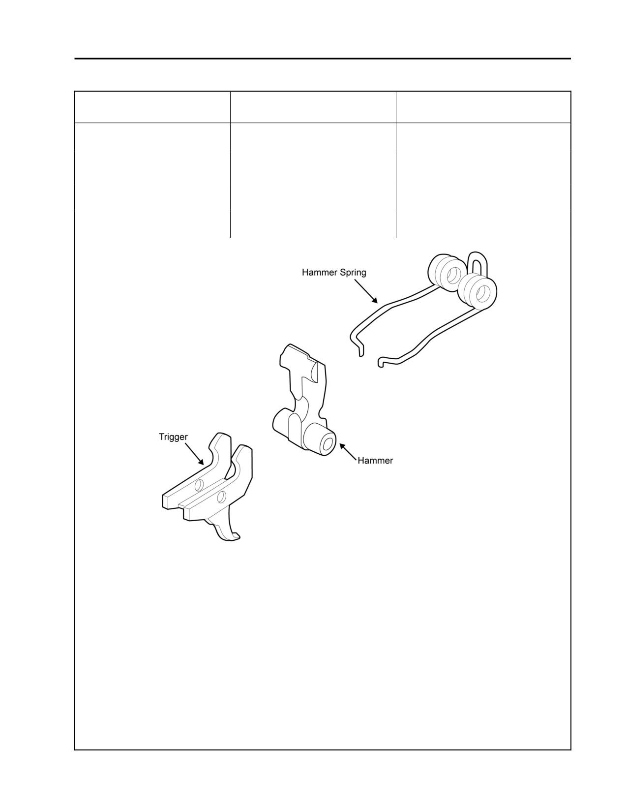
9. Failure to cock.
a. Short recoil.
Refer to Short Recoil in this table
(# 10).
b. Worn or broken hammer
Replace hammer spring. Refer to
spring. Refer to Figure 13.
WP 0013 00.
c. Worn or broken trigger.
Replace the trigger. Refer to
WP 0013 00.
d. Worn or broken hammer.
Replace the hammer. Refer to
WP 0013 00.
Figure 13. Trigger, Hammer. and Hammer Spring.
0006 00-9
TM 8370-50007-IN/2
0006 00
Table 1. Troubleshooting Procedures - Continued.
Malfunction
Test or Inspection
Corrective Action
10. Short recoil.
a. Defective recoil spring and
Replace recoil spring and guide rod
guide rod assembly.
assembly. Refer to WP 0010 00.
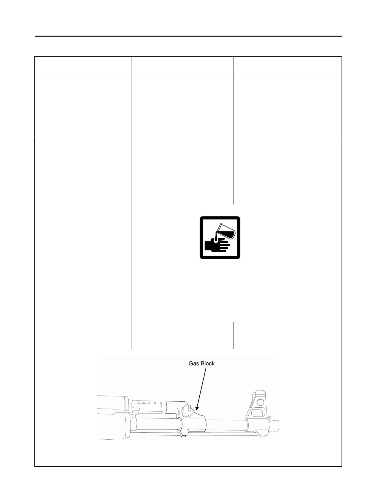
b. Dirty gas block, gas tube,
Clean and lubricate with CLP. Refer
recoil spring and guide rod
to WP 0010 00 and WP 0013 00.
assembly, or bolt carrier
assembly (gas piston and bolt
carrier).
c. Excessive gas leakage
Replace the gas tube. If the gas
caused by defective gas tube
block is defective, replace the
or gas block. Pitting due to
weapon. Refer to
use of corrosive ammunition
TM 8370-50047-OR/1.
d. Weak or broken gas piston.
Replace the bolt carrier assembly.
Refer to WP 0010 00.
e. Gas selector is in the wrong
Rotate the gas selector. Refer to
position.
WP 0013 00.
WARNING
When using carbon removing compound, wearing gloves and
protective equipment is required. Avoid contact with skin. If
carbon removing compound comes in contact with skin, wash
thoroughly with running water, and apply a lanolin-based
cream, if possible. Failure to follow this warning may cause
injury or death to personnel.
f.
Carbon build-up in barrel/gas
Remove carbon build-up by soaking
block.
the barrel in carbon removing
compound.
Figure 14. Gas Block.
0006 00-10
TM 8370-50007-IN/2
0006 00
Table 1. Troubleshooting Procedures - Continued.
Malfunction
Test or Inspection
Corrective Action
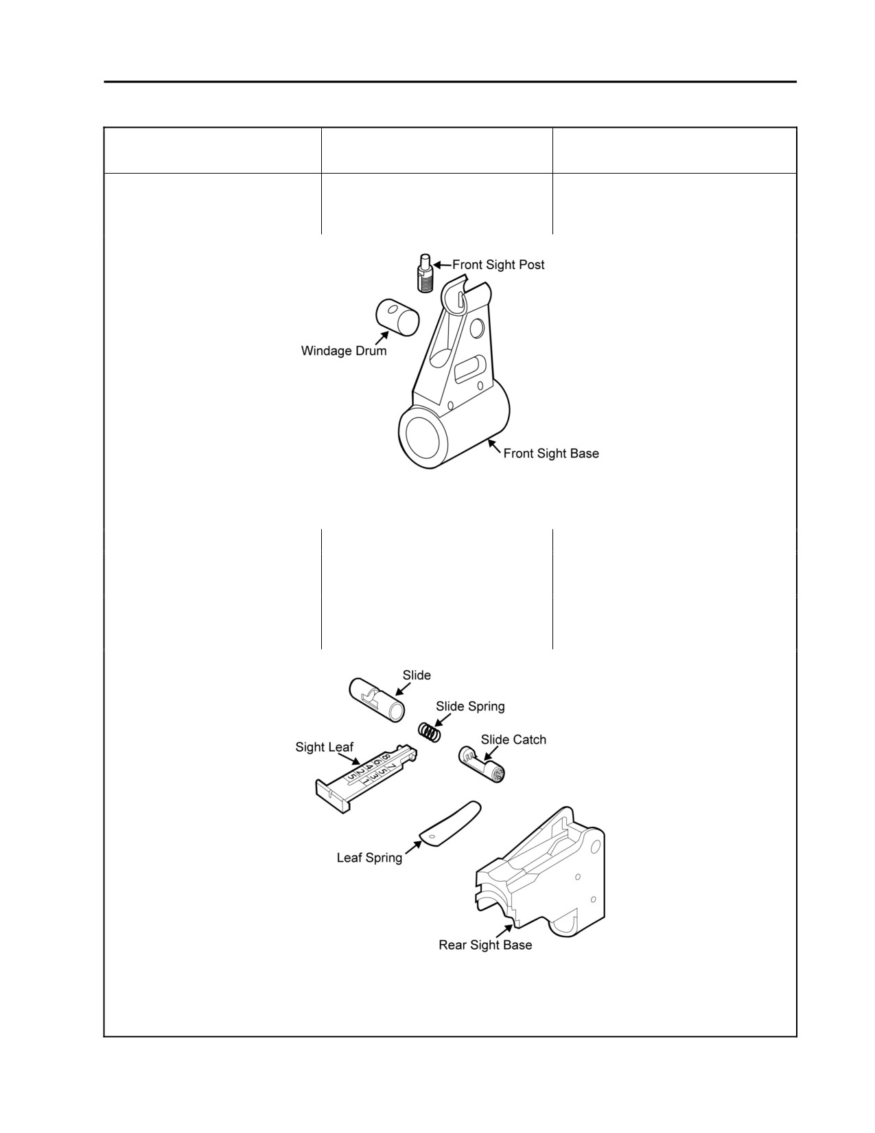
11. Rifle cannot be zeroed.
a. Defective front sight post.
Remove the front sight post. If
Refer to Figure 15.
damaged, replace. Refer to
WP 0013 00.
Figure 15. Front Sight Assembly.
b. Defective or bent barrel.
Replace weapon.
c. For elevation: defective rear
Repair the rear sight as required.
sight. Refer to Figure 16.
Refer to WP 0013 00.
d. For elevation: improperly
Properly assemble the rear sight.
assembled rear sight. Refer to
Refer to WP 0013 00 and
Figure 16.
WP 0014 00.
Figure 16. Rear Sight Assembly.
0006 00-11
TM 8370-50007-IN/2
0006 00
Table 1. Troubleshooting Procedures - Continued.
Malfunction
Test or Inspection
Corrective Action
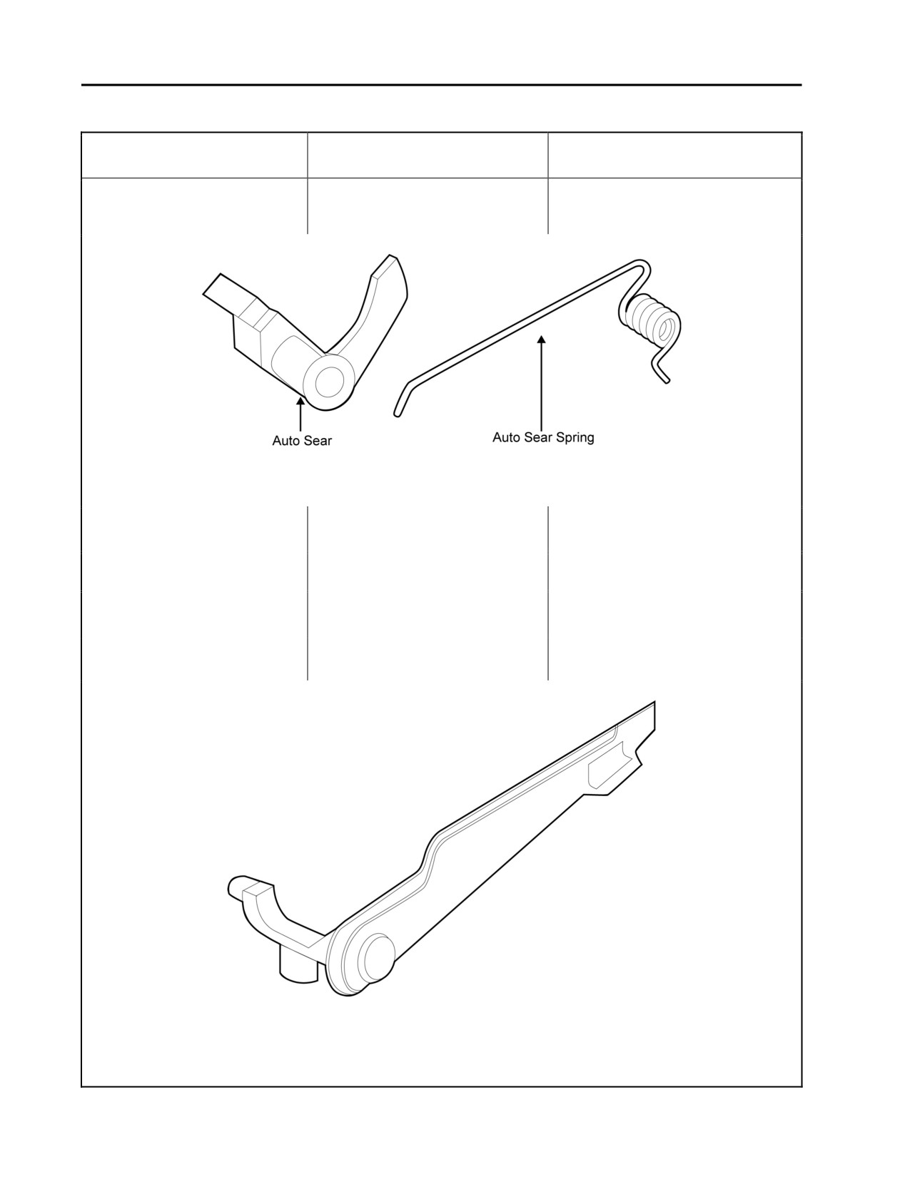
12. Failure to cycle with selector
a. Broken or worn auto sear or
Replace the auto sear or auto sear
lever on AUTO.
auto sear spring. Refer to
spring. Refer to WP 0013 00.
Figure 17.
Figure 17. Auto Sear and Auto Sear Spring.
b. Defective selector lever. Refer
Replace the selector lever. Refer to
to Figure 18.
WP 0013 00.
c. Short recoil.
Refer to Short Recoil in this table
(# 10).
13. Weapon fires with selector
a. Defective selector lever. Refer
Replace the selector lever. Refer to
lever on SAFE or when
to Figure 18.
WP 0013 00.
trigger is released with
b. Worn or broken trigger.
Replace the trigger. Refer to
selector lever on SEMI.
WP 0013 00.
Figure 18. Selector Lever.
0006 00-12
TM 8370-50007-IN/2
0006 00
Table 1. Troubleshooting Procedures - Continued.
Malfunction
Test or Inspection
Corrective Action
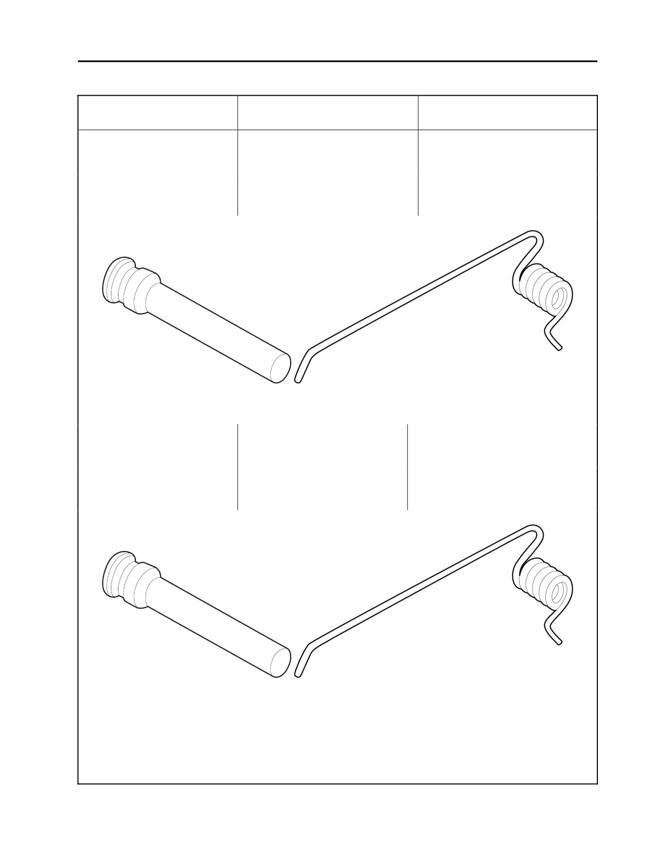
14. Auto sear retaining pin
a. Worn or broken auto sear
Replace the auto sear retaining pin
“walks” or works loose
retaining pin or auto sear
or the auto sear spring. Refer to
during firing, or auto sear
spring. Refer to Figure 19.
WP 0013 00.
retaining pin is very easy to
b. Long leg of auto sear spring set
Install the long leg of the auto sear
push out of receiver.
incorrectly into groove in the
spring correctly. Refer to
auto sear retaining groove.
WP 0013 00.
Figure 19. Auto Sear Retaining Pin and Auto Sear Spring.
15. Hammer retaining pin
a. Worn or broken hammer
Replace the hammer retaining pin or
“walks” or works loose
retaining pin or auto sear
auto sear spring. Refer to
during firing, or hammer
spring. Refer to Figure 20.
WP 0013 00.
retaining pin is very easy to
b. Long leg of auto sear spring
Install the long leg of the auto sear
push out of receiver.
set incorrectly into hammer
spring correctly. Refer to WP 0013 00.
retaining pin groove.
Figure 20. Hammer Retaining Pin and Auto Sear Spring.
0006 00-13

TM 8370-50007-IN/2
0006 00
Table 1. Troubleshooting Procedures - Continued.
Malfunction
Test or Inspection
Corrective Action
16. Trigger retaining pin “walks”
a. Worn or broken trigger
Replace the trigger retaining pin or
or works loose during firing,
retaining pin or auto sear
auto sear spring. Refer to
or trigger retaining pin is
spring. Refer to Figure 21.
WP 0013 00.
very easy to push out of
b. Long leg of auto sear spring
Install the long leg of the auto sear
receiver.
set incorrectly into trigger
spring correctly. Refer to
retaining pin groove.
WP 0013 00.
Figure 21. Trigger Retaining Pin and Auto Sear Spring.
17. Runaway gun.
a. Defective auto sear. Refer to
Replace the auto sear. Refer to
Figure 22.
WP 0013 00.
b. Worn or defective
Replace the disconnector. Refer to
disconnector. Refer to
WP 0013 00.
Figure 22.
c. Defective hammer or the top
Replace the hammer. Refer to
of hammer is worn. Refer to
WP 0013 00.
Figure 22.
Figure 22. Auto Sear, Disconnector, and Hammer.
END OF WORK PACKAGE
0006 00-14

TM 8370-50007-IN/2
CHAPTER 3
ORGANIZATIONAL MAINTENANCE

INTENTIONALLY BLANK

TM 8370-50007-IN/2
0007 00
SERVICE UPON RECEIPT
GENERAL
1. Inspect the weapon for damage incurred during shipment. If the weapon has been damaged, report the
damage on SF 364, Report of Discrepancy (ROD).
2. Check the weapon against the packing slip to see if the shipment is complete.
3. Check to see if the weapon has been modified.
4. Check the weapon for damage upon its receipt. Perform limited technical inspection as outlined in
Table 1 of this work package.
Table 1. Service Upon Receipt.
Location
Item
Action
Remarks
Container
1.
AK-47
a. Remove weapon from
containers.
b. Inspect the weapon for damage
If the weapon has
incurred during shipment.
been damaged, report
damage on SF 364..
c. Check the weapon against the
Report all
packing list to see if the
discrepancies
shipment is complete.
2.
Supply system
Check for missing items.
Refer to
responsibility items
TM 8370-50007 OR/1.
(SSRI)
3.
Barrel assembly
If volatile corrosion inhibitor (VCI) is
in the barrel, remove and discard.
AK-47 rifle
1.
All parts
a. Field strip the weapon and
Refer to
inspect for missing, damaged,
TM 8370-50007 OR/1.
and rusted or corroded parts.
b. Clean and lubricate
Refer to
TM 8370-50007 OR/1.
c. Reassemble.
Refer to
TM 8370-50007 OR/1.
d. Function check.
Refer to WP 0017 00.
e. Check to see if the weapon has
Report all
been modified.
modifications.
f.
Conduct initial gaging.
Refer to WP 0021 00
2.
Magazine
Check for positive retention of
Refer to
magazine.
TM 8370-50007 OR/1.
END OF WORK PACKAGE
0007 00-1/2 blank

INTENTIONALLY BLANK

TM 8370-50007-IN/2
0008 00
PREVENTIVE MAINTENANCE CHECKS AND SERVICES (PMCS), INCLUDING LUBRICATION
INSTRUCTIONS
GENERAL
This work package contains procedures and instructions necessary to perform organizational preventive
maintenance checks and services (PMCS), along with disassembly and reassembly procedures required for
corrective maintenance for the AK-47 rifle.
1. Organizational Maintenance. Organizational maintenance is performed at the using unit beyond the
capabilities of the operator as identified in TM 8370-50007-OR/1. Organizational maintenance is
authorized to service, replace, and adjust the parts and assemblies covered in the Organizational portion
of this manual.
2. Intermediate through Depot Maintenance. This is not applicable to this platform. All maintenance is
performed at the organizational level or the weapon is replaced.
3. Special Tools; Test, Measuring, and Diagnostic Equipment (TMDE); and Support Equipment.
Special tools and TMDE required for support are listed in WP 0025 00. There are no fabricated tools for
this weapons.
4. Repair Parts. Repair parts are listed and illustrated in WP0027 00.
WARNING
Ensure that the weapon is unloaded and that the selector lever is set on SAFE
before performing the following procedures. Do not keep live ammunition
near the work area. Failure to follow these warnings may cause injury or
death to personnel.
NOTES
PMCS is to be performed every 90 days to keep the weapon ready for use. If
the weapon has not been used for 90 days, PMCS described in the operator’s
manual (TM 8370-50007-OR/1) should also be performed.
Solid film lubricant (SFL) is authorized to be used as a touch up for the
exterior protective finish on the AK-47.
5.
General. The PMCS procedures are contained in the following table. They are arranged in logical
sequence requiring a minimum amount of time and motion on the part of the persons performing them
and are arranged so that there will be minimum interference between the persons performing
simultaneous checks on the same end item.
6.
Item Number Column. This column describes checks and services numbered in disassembly sequence.
7.
Interval Column. This column states the designated interval when each check is to be performed.
8.
Item to Check/Service Column. This column lists the items to be checked or serviced.
0008 00-1
TM 8370-50007-IN/2
0008 00
9. Procedure Column. This column contains a brief description of the procedure by which the check is to
be performed. It contains all the information required to accomplish the checks and services.
10. Not Fully Mission Capable if Column. This column states which faults will prevent the weapon from
being capable of performing its primary mission. The weapon should not be used if it meets any of the
faults listed in this column.
11. Other Table Entries. Observe all WARNINGs, CAUTIONs, and NOTEs.
Table 1. Preventive Maintenance Checks and Services for the AK-47 Rifle.
Item
Interval
Location or Item to
Procedure
Not Fully Mission
No.
Check/Service
Capable if:
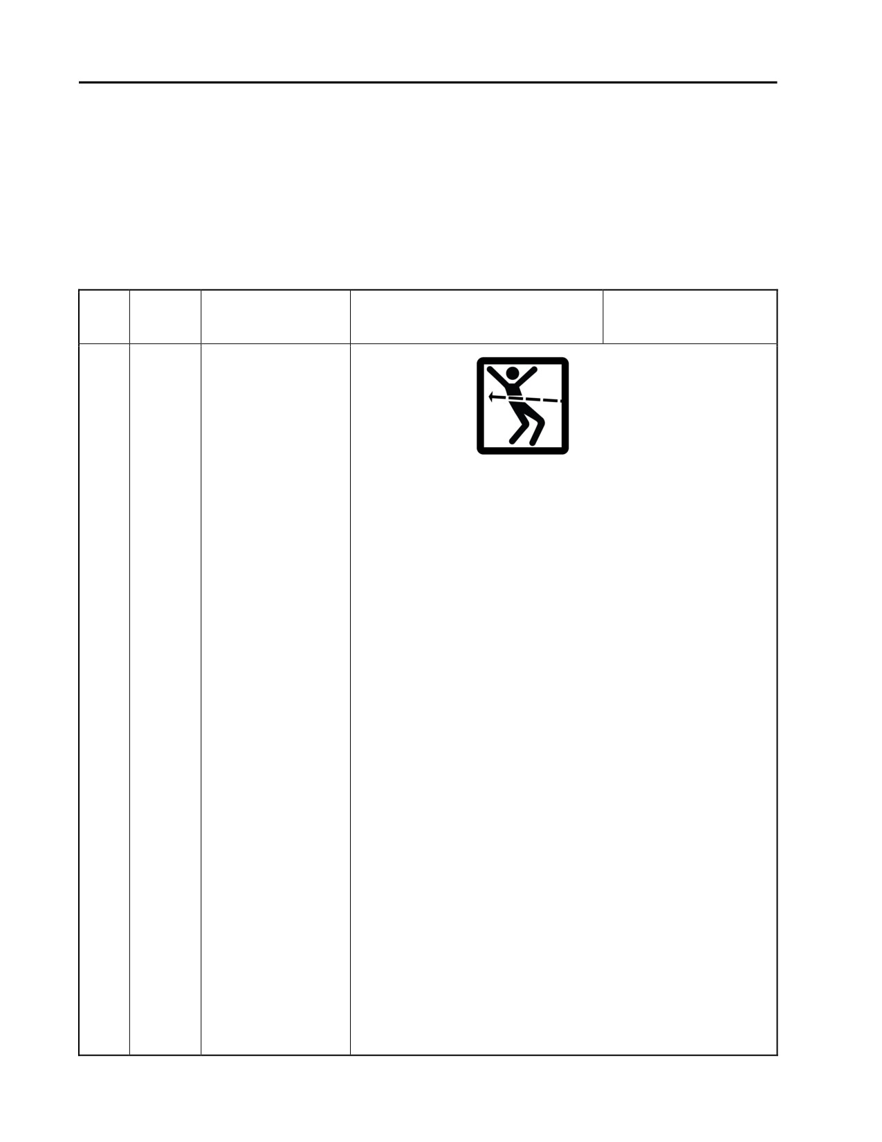
WARNING
Before starting an inspection, be sure to clear the
weapon. Do not pull the trigger until the weapon has
been cleared. Inspect the chamber to ensure that it is
empty and no ammunition is in position to be
chambered. DO NOT keep live ammunition in the work
area. Failure to follow these warnings may cause injury
or death to personnel.
NOTES
An inactive weapon is a weapon that has been stored in
an arms room for a period of 90 days without use.
Inactive weapons should receive quarterly PMCS
unless inspection reveals more frequent servicing is
necessary.
If the unit armorer detects corrosion on a weapon prior
to the end of the 90 day period, the PMCS should be
performed immediately.
SFL is the authorized touch up for the AK-47 rifle.
0008 00-2
TM 8370-50007-IN/2
0008 00
Table 1. Preventive Maintenance Checks and Services for the AK-47 Rifle - Continued.
Item
Interval
Location or Item to
Procedure
Not Fully Mission
No.
Check/Service
Capable if:
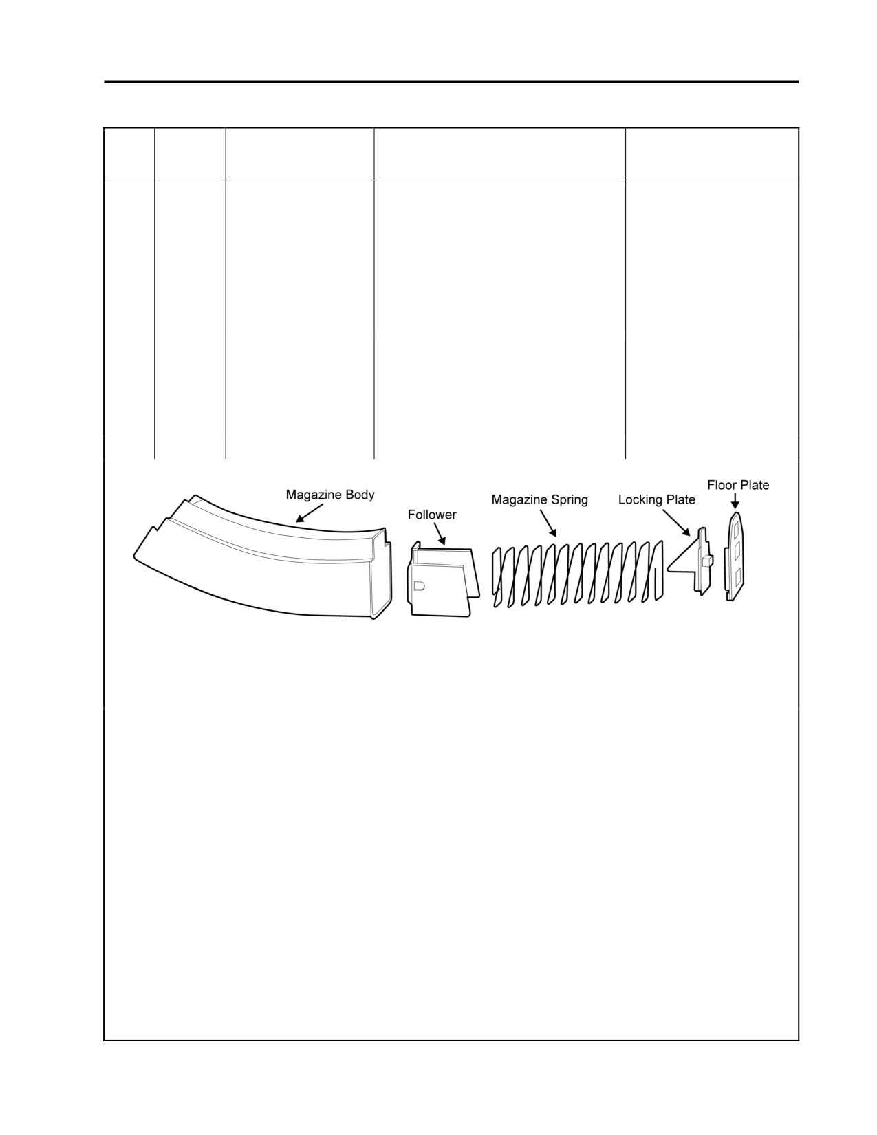
1
Quarterly
Magazine
a. Disassemble
A magazine is not
(Serviceability Check)
(TM 8370-50007-OR/1). Inspect
available for use with the
the magazine body for bulges,
rifle.
dents, or damaged feeder lips.
Inspect the spring and follower
for bends, kinks, or damage.
Replace the magazine if any of
these conditions exist. Refer to
Figure 1.
b. Reassemble the magazine and
(1) The body is dented
check for binding when
or feeder lips on top
depressing and releasing the
of the body are
follower. Replace the magazine if
damaged. The
the follower binds. Refer to
spring is damaged or
Figure 1.
has flat spots.
(2) The follower binds.
Figure 1. Magazine Components.
0008 00-3
TM 8370-50007-IN/2
0008 00
Table 1. Preventive Maintenance Checks and Services for the AK-47 Rifle - Continued.
Item
Interval
Location or Item to
Procedure
Not Fully Mission
No.
Check/Service
Capable if:
2
Quarterly
Selector Lever,
Function Check
WARNING
Ensure the weapon is clear prior to performing the
following function checks. If the weapon fails any of
the following function checks, attempt to repair. If
beyond repair, replace the weapon.
Selector Lever
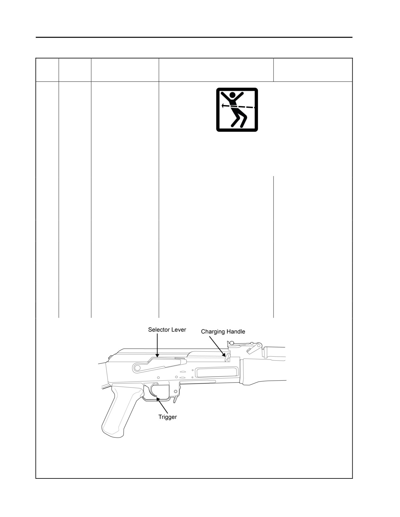
a. Pull and hold the charging handle
The bolt does not lock
- SEMI
to the rear. Check that the
forward.
chamber is clear. Let the bolt
carrier close forward. Refer to
Figure 2.
b. Leave the hammer in the cocked
position. Do not pull the trigger.
- SAFE
a. Place the selector lever in SAFE
position.
b. Pull the trigger. The hammer
The hammer falls.
should not fall.
a. Place the selector lever in SEMI
- SEMI
position.
b. Pull the trigger and hold it to the
The hammer does not
rear. The hammer falls.
fall.
Figure 2. Charging Handle, Trigger, and Selector Lever (Selector Lever on SAFE).
0008 00-4
TM 8370-50007-IN/2
0008 00
Table 1. Preventive Maintenance Checks and Services for the AK-47 Rifle - Continued.
Item
Interval
Location or Item to
Procedure
Not Fully Mission
No.
Check/Service
Capable if:
2
Quarterly
Selector Lever
NOTES
Cont.
For the purpose of the following test, SLOW is defined
as 1/4 to 1/2 the normal rate of trigger release.
DO NOT milk the trigger. Milking the trigger can cause
the hammer to fall.
c.
Hold the trigger to the rear,
The hammer falls.
-SEMI
charge the weapon, and release
the trigger with a SLOW, smooth
motion, without hesitations or
stops, until the trigger is fully
forward (an audible click should
be heard). The hammer should
not fall. (The hammer should not
fall until the trigger is pulled
again).
a.
Place the selector lever on
The hammer does not
- AUTO
AUTO. Charge the weapon. Pull
fall.
the trigger and hold it to the rear.
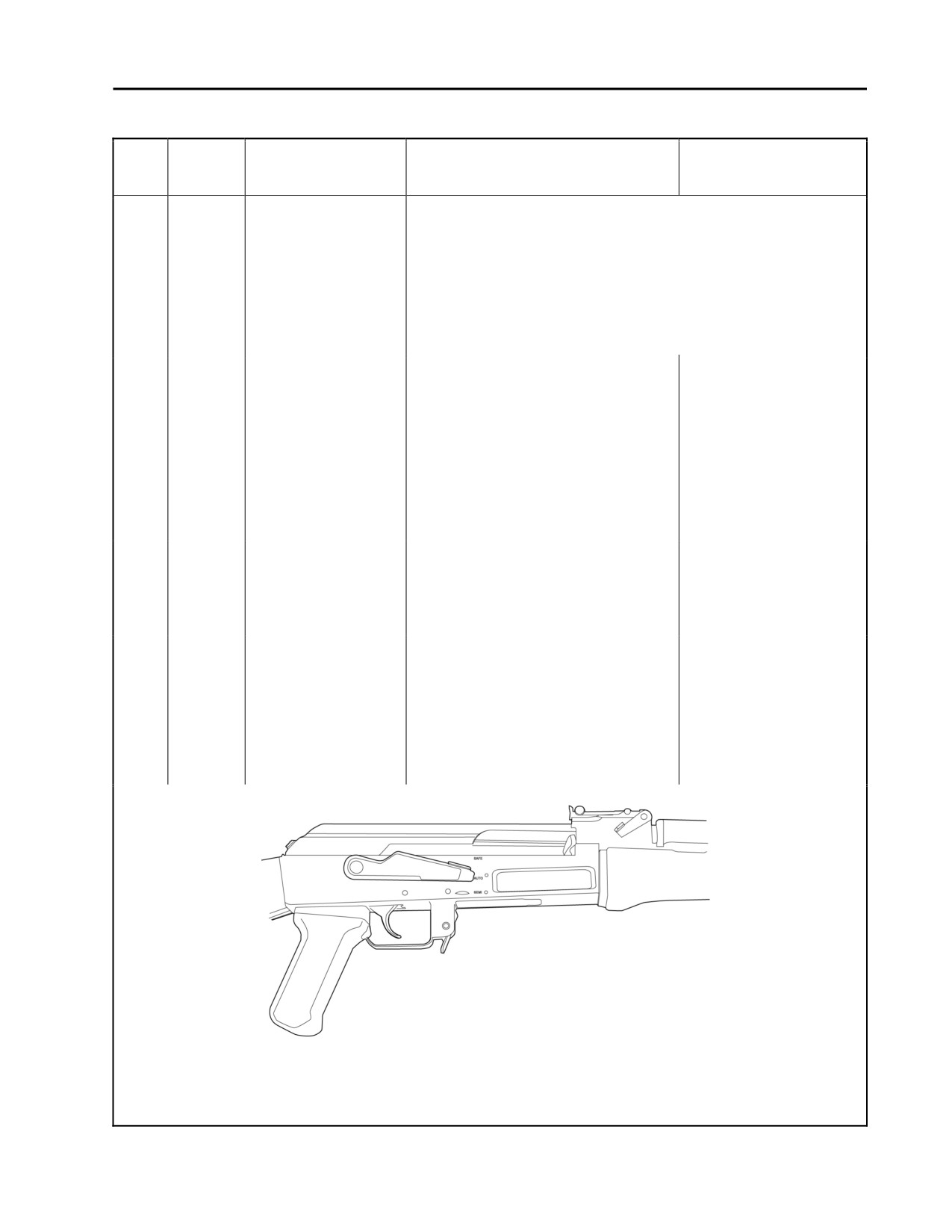
The hammer should fall. Refer to
Figure 3.
b.
Holding the trigger to the rear,
The hammer falls when
charge the weapon and release
the trigger is pulled the
the trigger. Pull the trigger a
second time.
second time. The hammer should
not fall. (The hammer should
have been released by the auto
sear when the weapon was
charged.)
Figure 3. Selector Lever on AUTO.
0008 00-5
TM 8370-50007-IN/2
0008 00
Table 1. Preventive Maintenance Checks and Services for the AK-47 Rifle - Continued.
Item
Interval
Location of Item to
Procedure
Not Fully Mission
No.
Check/Service
Capable if:
2
Quarterly
Selector Lever
With the hammer in the forward
Moderate finger/thumb
Cont.
-AUTO
position, using moderate finger/thumb
pressure does NOT move
pressure, attempt to place the
the selector lever to the
selector lever on the SAFE position.
SAFE position.
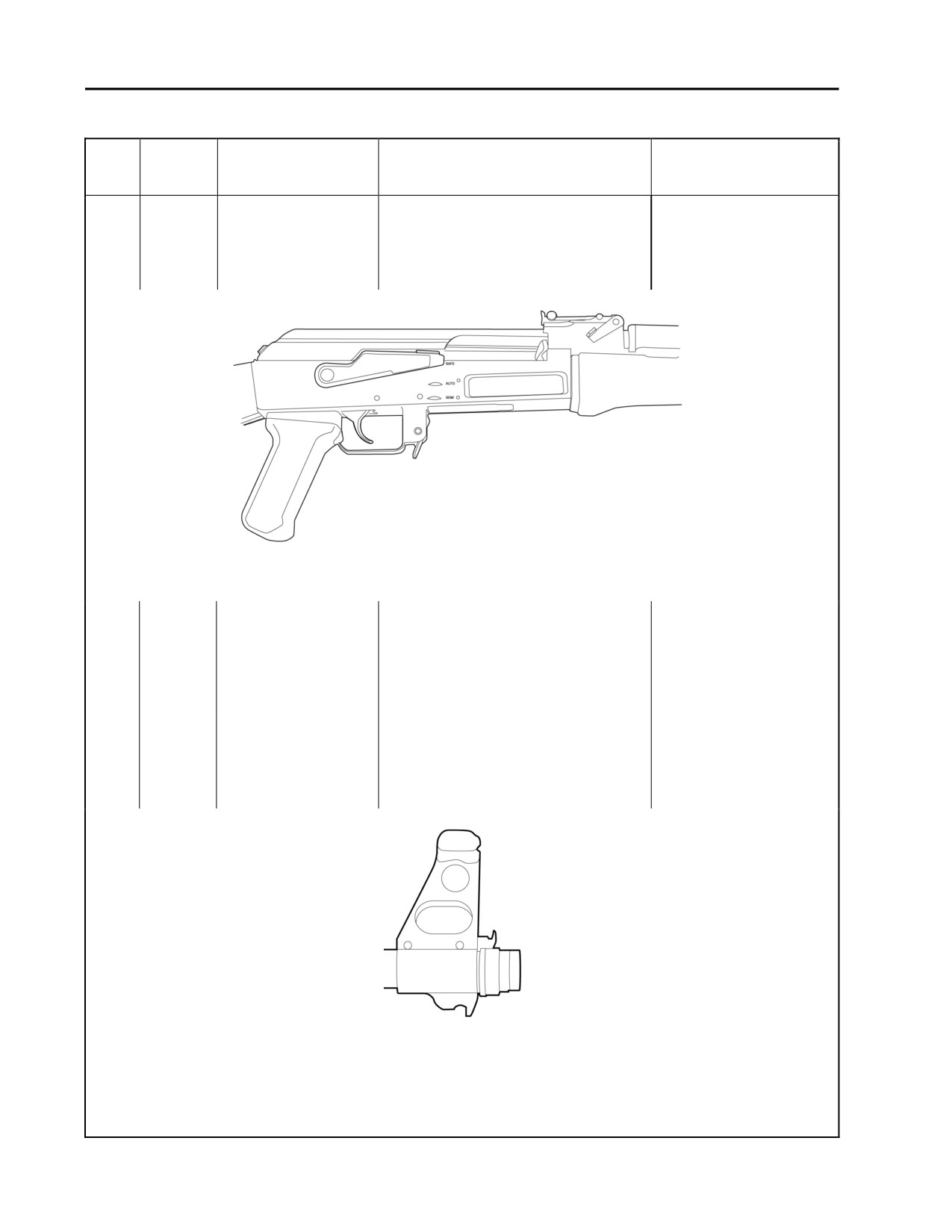
Refer to Figure 4.
Figure 4. Selector Lever on SAFE.
3
Quarterly
Receiver Assembly
a. Apply a light coat of CLP to all
metal parts. Remove any rust,
dirt, or debris. Remove any burrs.
Lubricate all moving parts.
Remove excess lubricant. Refer
to WP 0009 00.
b. Hand check the thread protector
The thread protector or
for looseness on the barrel, then
barrel is loose.
hand check the barrel for
looseness on the receiver. Refer
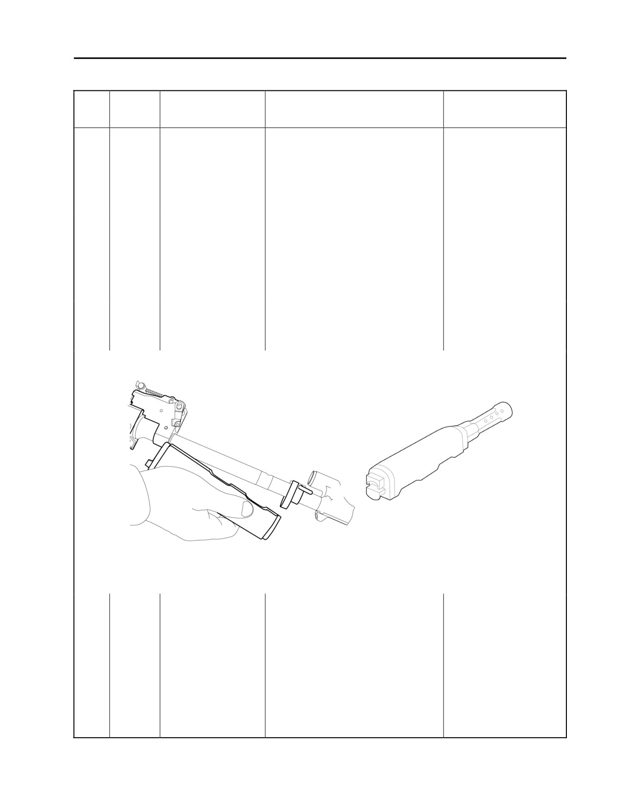
to Figure 5.
Figure 5. Thread Protector.
0008 00-6
TM 8370-50007-IN/2
0008 00
Table 1. Preventive Maintenance Checks and Services for the AK-47 Rifle - Continued.
Item
Interval
Location of Item to
Procedure
Not Fully Mission
No.
Check/Service
Capable if:
3
Quarterly
Receiver Assembly
c. Remove the lower handguard
The handguards are
Cont.
and the upper handguard and
missing or defective.
gas tube. Refer to
TM 8370-50007-OR/1. Inspect
the handguards internally and
externally for cracks and
damage. Refer to Figure 6.
d. Cracks are acceptable providing
they do not extend into the front
or rear of the handguards or
adversely affect the weapon’s
operation, operator safety, or
proper retention of the
handguard. Refer to Figure 6.
e. Check the gas tube for
The gas tube has
deformities or holes. Remove
deformities, holes, carbon
carbon deposits or debris. Refer
deposits, or debris.
to Figure 6.
Figure 6. Lower Handguard and Upper Handguard and Gas Tube.
f.
Check the gas selector, gas
The gas selector, gas
block, and rear sight assembly
block, or rear sight
for damage and functionality.
assembly is
unserviceable or
damaged.
0008 00-7
TM 8370-50007-IN/2
0008 00
Table 1. Preventive Maintenance Checks and Services for the AK-47 Rifle - Continued.
Item
Interval
Location or Item to
Procedure
Not Fully Mission
No.
Check/Service
Capable if:
3
Quarterly
Receiver Assembly
g. Inspect the pistol grip screw and
The pistol grip is
Cont.
pistol grip for defects or
defective or loose.
looseness on the receiver.
h. Check the magazine release for
The magazine release
magazine retention.
will not retain a
magazine.
i.
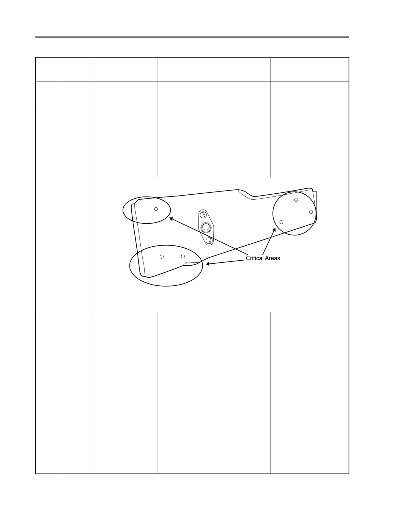
Check the fixed buttstock (if
The fixed buttstock has
present) for defects. A total of
more than three cracks or
three cracks are acceptable.
any cracks near critical
However, cracks near critical
areas.
areas (near pins or screws) are
not acceptable. Refer to Figure 7.
Figure 7. Fixed Buttstock.
j.
Check the fixed buttstock (if
The fixed buttstock is
present) for looseness on the
loose.
receiver. If it is loose, remove the
screws, clean the threads, apply
thread-locker, and reinstall the
screws. If necessary, replace the
buttstock screws or buttstock.
k. Check the folding buttstock (if
The folding buttstock is
present) for cracks and bends.
damaged, will not fold
Ensure it will fold and extend.
and extend, or lock in
Ensure it will lock in both
both positions.
positions. Lubricate all joints and
moving parts.
0008 00-8
TM 8370-50007-IN/2
0008 00
Table 1. Preventive Maintenance Checks and Services for the AK-47 Rifle - Continued.
Item
Interval
Location or Item to
Procedure
Not Fully Mission
No.
Check/Service
Capable if:
3
Quarterly
Receiver Assembly
l.
Raise and lower the rear sight
The rear sight leaf spring
Cont.
assembly. The rear sight leaf
will not retain the rear
spring should retain the rear sight
sight assembly in either
assembly in both positions with
position
firmness.
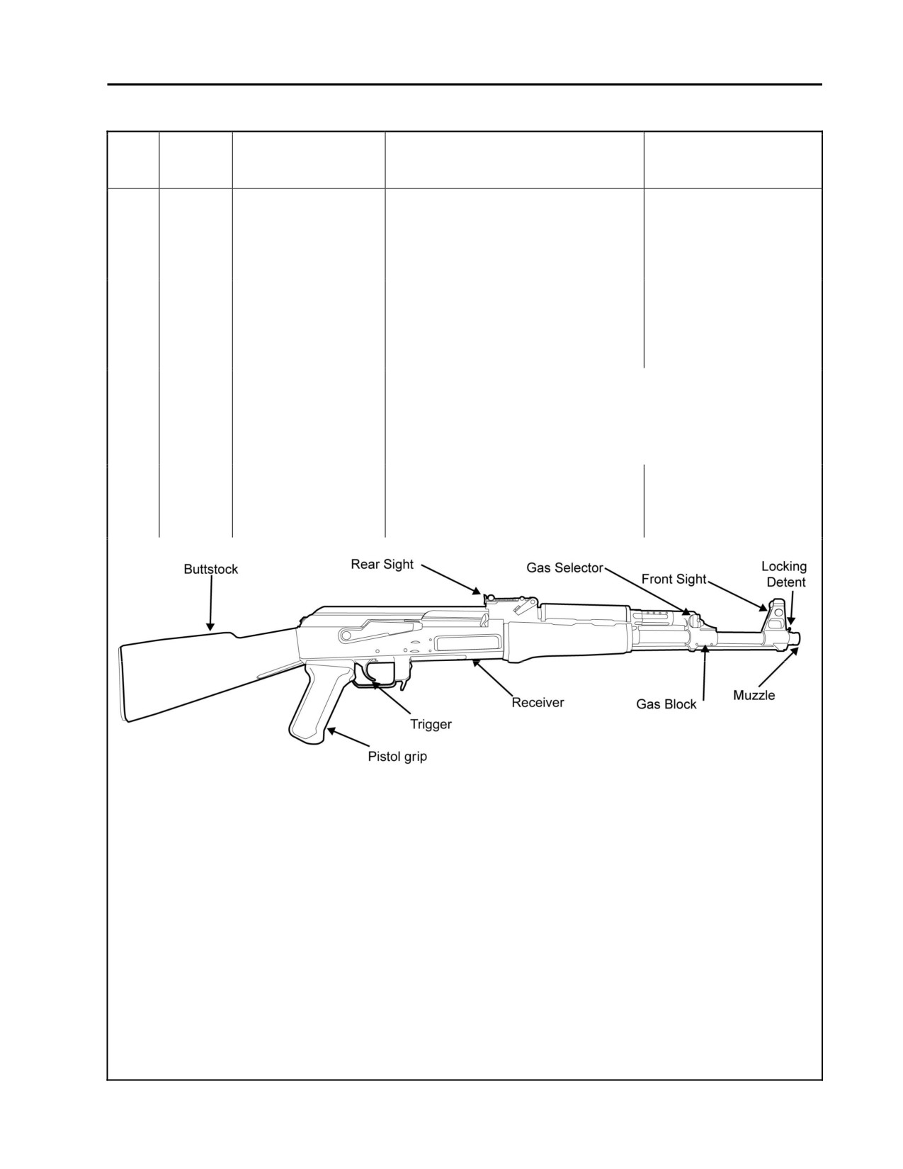
m. Check the front sight base, post,
The front sight base,
locking detent, and detent spring
post, locking detent, or
for damage or corrosion. Clean
detent spring are
and lubricate the parts. Refer to
damaged or corroded.
Figure 8.
NOTE
If the front or rear sight is moved, return it to its
original position.
n. Check the sling swivel that is
The sling swivel is
located on the left side of the gas
defective.
block for damage and proper
function.
Figure 8. Receiver Assembly and Components.
0008 00-9
TM 8370-50007-IN/2
0008 00
Table 1. Preventive Maintenance Checks and Services for the AK-47 Rifle - Continued.
Item
Interval
Location or Item to
Procedure
Not Fully Mission
No.
Check/Service
Capable if:
3
Quarterly
Receiver Assembly
Cont.
WARNINGS
Dry cleaning solvent is flammable and toxic and should
be used in a well-ventilated area. The use of rubber
gloves is necessary to protect the skin when washing
weapon parts. Failure to follow this warning may cause
injury or death to personnel.
CAUTION
DO NOT use a wire brush to roughen the surfaces. Use
a well-ventilated area during cleaning and the
application of solid film lubricant (SFL). If SFL comes
in contact with moving parts or functioning surfaces of
the weapon, remove the SFL immediately by washing
the area with dry cleaning solvent.
NOTE
Shiny metal exterior surfaces of the weapon should be
recoated with SFL. Clean the surface with dry cleaning
solvent, dry, roughen with abrasive cloth, and apply
solid film lubricant.
o.
Inspect the receiver finish for
scratches or worn, shiny spots.
p.
If scratched or worn shiny spots
are present, disassemble the
receiver assembly and remove all
lubricant from the surface with
dry cleaning solvent.
q.
Wear chemical and oil protective
gloves and use a wash pan (tote
box) to apply the solvent. Let the
parts dry thoroughly. Roughen
the surface using abrasive cloth
and apply SFL. Allow 16 to 24
hours drying time before
handling.
0008 00-10

TM 8370-50007-IN/2
0008 00
Table 1. Preventive Maintenance Checks and Services for the AK-47 Rifle - Continued.
Item
Interval
Location or Item to
Procedure
Not Fully Mission
No.
Check/Service
Capable if:
4
Quarterly
Bolt Carrier Assembly
WARNING
During general maintenance, DO NOT interchange bolt
assemblies from one weapon to another without
checking for the proper headspace. Refer to
WP 0021 00. Failure to follow this warning may cause
injury or death to personnel.
a.
Disassemble (WP 0011 00 and
The bolt carrier assembly
WP 0012 00) and inspect the bolt
or bolt assembly are
carrier assembly and bolt
defective.
assembly for defects. Refer to
Figure 8.
b.
Check the bolt for an elongated
The firing pin hole is
or cracked firing pin hole. If the
elongated or cracked.
firing pin hole is elongated or
cracked, replace the bolt. Refer
to Figure 8.
c.
Check for a broken or missing
There is a missing or
firing pin retaining pin. Replace
broken firing pin retaining
the pin if necessary. Refer to
pin.
Figure 8.
d.
Check the cartridge extractor and
The parts are missing or
extractor spring for defects and
unserviceable.
serviceability. If the cartridge
extractor or extractor spring are
dirty, clean, lubricate, and
assemble them. Replace them as
necessary. Refer to Figure 8.
e.
Check the bolt carrier assembly
The bolt carrier assembly
(bolt carrier and gas piston) for
is damaged.
defects. Replace the bolt carrier if
necessary. Refer to Figure 8.
0008 00-11
TM 8370-50007-IN/2
0008 00
Table 1. Preventive Maintenance Checks and Services for the AK-47 Rifle - Continued.
Item
Interval
Location or Item to
Procedure
Not Fully Mission
No.
Check/Service
Capable if:
4
Bolt Carrier Assembly
f.
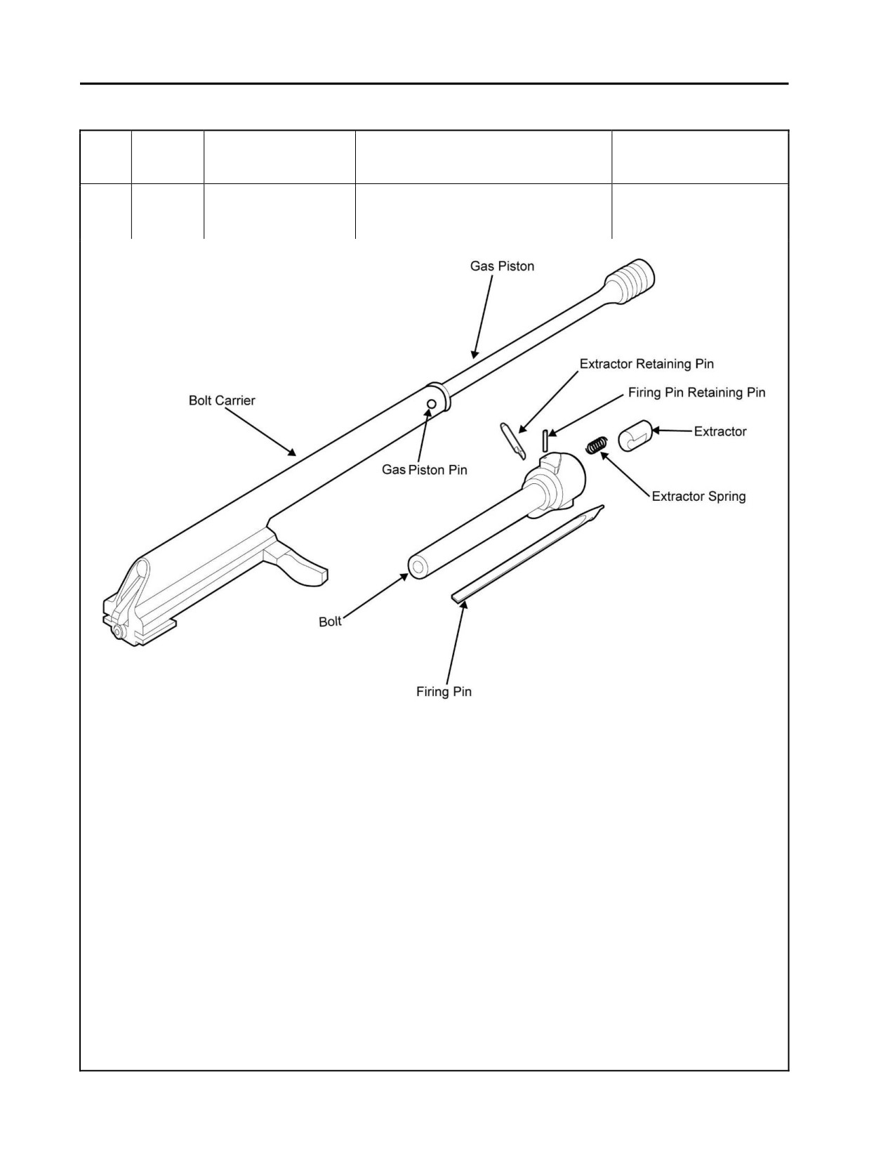
Check the firing pin for defects. If
The firing pin is
Cont.
and Bolt Assembly
the firing pin is damaged, replace
damaged.
it. Refer to Figure 9.
Figure 9. Bolt Carrier Assembly and Bolt Assembly Components.
0008 00-12
TM 8370-50007-IN/2
0008 00
Table 1. Preventive Maintenance Checks and Services for the AK-47 Rifle - Continued.
Item
Interval
Location or Item to
Procedure
Not Fully Mission
No.
Check/Service
Capable if:
5
Quarterly
Recoil Spring and
Check the recoil spring and guide rod
The recoil spring and
Guide Rod Assembly
assembly for straightness, spring
guide rod assembly has
tension, and defects. Replace if
weak spring tension, is
necessary. Refer to Figure 10.
bent, or defective.
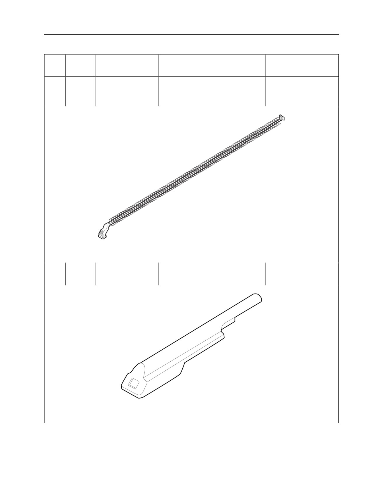
Figure 10. Recoil Spring and Guide Rod Assembly.
6
Quarterly
Top Cover
Check the top cover for dents.
The top cover is dented.
Replace the top cover if dented.
Refer to Figure 11.
Figure 11. Top Cover.
END OF WORK PACKAGE
0008 00-13/14 blank

INTENTIONALLY BLANK
TM 8370-50007-IN/2
0009 00
GENERAL MAINTENANCE INSTRUCTIONS
THIS WORK PACKAGE DESCRIBES
Scope, Work Safety, General Information, Cleaning Instructions, Inspection Instructions, Repair Instructions,
Lubrication Instructions, Standard Tool Requirements, Applying Torque, and Tagging Instructions.
INITIAL SETUP
Maintenance Level
References
Organizational
TM 4795-12/1_
TM 9-247_
WP 0008 00
SCOPE
The following general maintenance instructions contain general shop practices and specific methods used to
properly maintain the AK-47 rifle.
WORK SAFETY
1. Before beginning the following tasks, ensure safety by wearing protective gear such as safety goggles or
lenses, safety shoes, rubber apron, and gloves.
2. Observe all WARNINGs, CAUTIONs, and NOTEs.
GENERAL INFORMATION
Before beginning a task, determine how much repair, modification, or replacement is needed to repair the
weapon as described in this manual. Occasionally, the cause of equipment failure is apparent and complete
disassembly of the weapon is unnecessary. Should disassembly be necessary, only disassemble the weapon so
far as necessary to repair or replace the broken parts.
CLEANING INSTRUCTIONS
WARNINGS
Use only cleaner, lubricant, and preservative
(CLP) for cleaning and
lubrication of the AK-47 rifle in all but the most severe conditions.
Improper cleaning methods and use of unauthorized cleaning solvents may
injure personnel and damage equipment. Refer to TM 9-247_, Materials
Used for Cleaning, Preserving, Abrading, and Cementing Ordnance
Materials and Related Materials Including Chemicals for correct
information.
Cloths or rags saturated with solvent cleaning compound must be disposed of
in accordance with authorized facilities’ procedures.
0009 00-1

TM 8370-50007-IN/2
0009 00
WARNINGS - CONTINUED
Eye shields must be worn when cleaning with a wire brush. Flying rust and
metal particles may cause injury to personnel.
Particles blown by compressed air are hazardous. Use a maximum of 30 psi
when cleaning components. DO NOT exceed 15 psi nozzle pressure when
drying parts with compressed air.
DO NOT direct compressed air against human skin. Make sure air stream is
directed away from the user and other personnel in the area. To prevent
injury, the user must wear protective goggles or a face shield.
Failure to follow these warnings may result in injury or death to personnel.
CAUTIONS
Do not mix multiple lubricants on the same weapon. The weapon must be
cleaned thoroughly when changing from one lubricant to another. Dry
cleaning solvent (SD) is recommended for removing the old lubricant before
changing to another lubricant.
DO NOT allow CLP or any other solvent to come in contact with telecopic
sight lenses or other optical devices.
NOTE
When the term lubricant or CLP is used in the following text, the lubricant
used can be either CLP; lubricating oil, semi-fluid, automatic weapons
(LSA); or lubricant, arctic, weapons (LAW). Cloths or rags saturated with
CLP must be disposed of in accordance with authorized facilities’
procedures. Cleaning instructions are the same for the majority of the parts
and components of the weapon.
Maintenance personnel must thoroughly understand the importance of cleaning. Great attention to detail is
required for cleaning the weapon. Dirt, dust, foreign material, and grit are a constant threat to satisfactory
performance of the weapon. Thorough cleaning ensures high weapon performance. The following should
apply to all cleaning, inspection, repair, and assembly operations.
1. Cleaning All Parts.
a. Clean all parts before inspection, after repair, and before assembly.
b. To prevent contamination, hands should be kept free of any accumulation of grease that can collect
dust, dirt, or grit.
c. After cleaning, all parts should be covered or wrapped to protect them from dust and dirt. Parts that
are subject to rust should be oiled lightly.
0009 00-2

TM 8370-50007-IN/2
0009 00
2. Cleaning Disassembled Parts.
a. Dry and cover all cleaned parts.
b. All parts subject to rusting must be lightly oiled and wrapped.
c. Keep all related parts and components together. Do not interchange parts with another weapon.
3. Castings.
a. Clean the inner and outer surfaces of castings with CLP.
b. Use a stiff brush to remove sludge and gum deposits.
c. Clear out all tapped (threaded) holes with compressed air to remove dirt and cleaning solvent.
4. Machined Surfaces.
a. Clean machined surfaces with a pipe cleaner.
b. Dry surfaces thoroughly with compressed air.
5. Mated Surfaces. Lightly coat with CLP and wrap all parts subject to rust before storing.
INSPECTION INSTRUCTIONS
1.
General. Carefully check all components and parts to determine if they are serviceable for reuse, or if
they must be scrapped.
2.
Drilled and Tapped (Threaded) Holes.
a. Inspect for wear, distortion (stretching), cracking, or any other damage in or around holes.
b. Inspect threaded areas for wear, distortion, or evidence of cross-threading.
3.
Castings.
a. Replace all cracked castings.
b. Inspect machined surfaces for nicks, burrs, or raised metal. Mark damaged areas for repair or
replacement.
c. Inspect all screws and screw openings for damaged or stripped threads.
4.
Studs, Bolts, and Screws. Replace if threads are damaged, bent, or stretched.
5.
Machine-Tooled Parts. Inspect parts for cracks, breaks, elongated holes, wear, and chips. Replace any
damaged parts.
6.
Machined Surfaces. Inspect machined surfaces for cracks, evidence of wear, galled or pitted surfaces,
burrs, nicks, and scratches.
7.
Mating Surfaces. Inspect mating surfaces for proper seal, secure fit, and pitting.
8.
Rusted Surfaces. Inspect rusted surfaces for pitting, holes, and severe damage.
0009 00-3

TM 8370-50007-IN/2
0009 00
9. Internal Parts. Inspect internal parts for cracks, nicks, burrs, evidence of overheating, and wear.
10. Externally Exposed Parts. Inspect externally exposed parts for breaks, cracks, rust damage, and wear.
11. Springs. Inspect springs for broken, collapsed, and twisted coils.
REPAIR INSTRUCTIONS
1. General. Any repair procedure for a specific part is covered in the working package related to that item.
CAUTION
Repaired items must be thoroughly cleaned to remove metal and abrasives to
prevent them from entering working parts of the weapon.
2. Castings. Only minor repairs to machined surfaces are permitted (e.g. removing minor nicks, burrs, and
scratches) using a fine-mill file and crocus cloth with solvent cleaning compound.
LUBRICATION INSTRUCTIONS
Refer to Preventive Maintenance Checks and Services (PMCS) (WP 0008 00) for detailed, illustrated
instructions on proper lubrication. The following are some general practices to remember.
1. Use the correct lubricant in accordance with TM 4795-12/1_, Organizational Corrosion Prevention and
Control Procedures for USMC Equipment.
2. Keep the lubricants clean.
3. Lubricate all clean, disassembled, and new parts to prevent rust.
STANDARD TOOL REQUIREMENTS
Some maintenance tasks may require special or fabricated tools. The initial setup of the procedure will specify
any special or fabricated tools needed to perform that procedure. Special tools should be used only for the
maintenance procedures for which they are designed or called out. If you are unfamiliar with a required tool,
see your supervisor.
APPLYING TORQUE
If a unique torque value is required, it will be provided in a procedural step in the task.
TAGGING INSTRUCTIONS
1. Use marker tags to identify all parts that may be hard to identify or replace later. Fasten the tags to parts
during removal by wrapping wire fasteners around or through the parts and twisting the ends together.
Position the tags out of the way during cleaning, inspection, and repair. Mark the tags with a pencil, pen,
or marker.
2. Identify and tag other parts by name and the installed location as required.
END OF WORK PACKAGE
0009 00-4
TM-8370-50007-IN/2
0010 00
DISASSEMBLY OF WEAPON
THIS WORK PACKAGE DESCRIBES
Disassembly.
INITIAL SETUP
Maintenance Level
Equipment Conditions
Organizational
Weapon cleared (TM 8307-50007-OR/1)
References
TM 8307-50007-OR/1
WARNING
Always assume that every weapon is loaded until it is determined through
visual and physical inspection that it is not. Procedures for clearing and
unloading the weapon are outlined in TM 8307-50007-OR/1. Failure to
follow this warning may cause injury or death to personnel.
DISASSEMBLY
Remove the magazine, cleaning rod, handguards, top cover, recoil spring and guide rod assembly, and bolt
carrier assembly and bolt assembly from the receiver.
Figure 1. Major Components of the AK-47 Disassembled.
END OF WORK PACKAGE
0010 00-1/2 blank

INTENTIONALLY BLANK
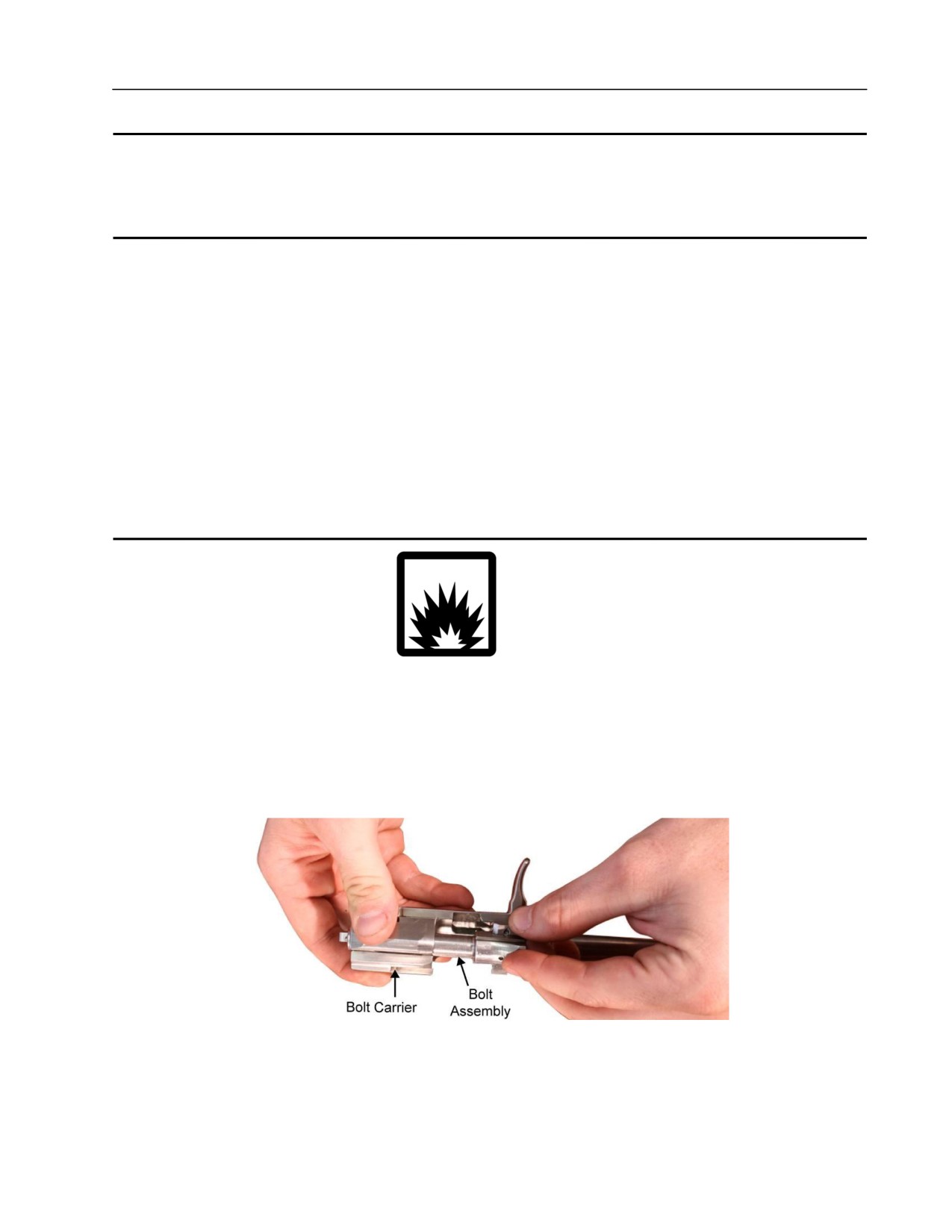
TM 8370-50007-IN/2
0011 00
BOLT CARRIER ASSEMBLY AND BOLT ASSEMBLY
THIS WORK PACKAGE DESCRIBES
Disassembly, Cleaning, Inspection and Repair, Lubrication, and Reassembly.
INITIAL SETUP
Maintenance Level
References
Organizational
TM 8370-50007-OR/1
WP 0010 00
Tools and Special Tools
WP 0012 00
WP 0025 00
E7900 tool kit
Equipment Conditions
Bolt carrier assembly and bolt assembly
removed (WP 0010 00)
WARNING
DO NOT interchange bolt assemblies from one weapon to another without
checking for the proper headspace. Failure to follow this warning may cause
injury or death to personnel.
DISASSEMBLY
1. Push the bolt assembly into the bolt carrier. Refer to Figure 1.
Figure 1. Pushing the Bolt Assembly into the Bolt Carrier.
0011 00-1
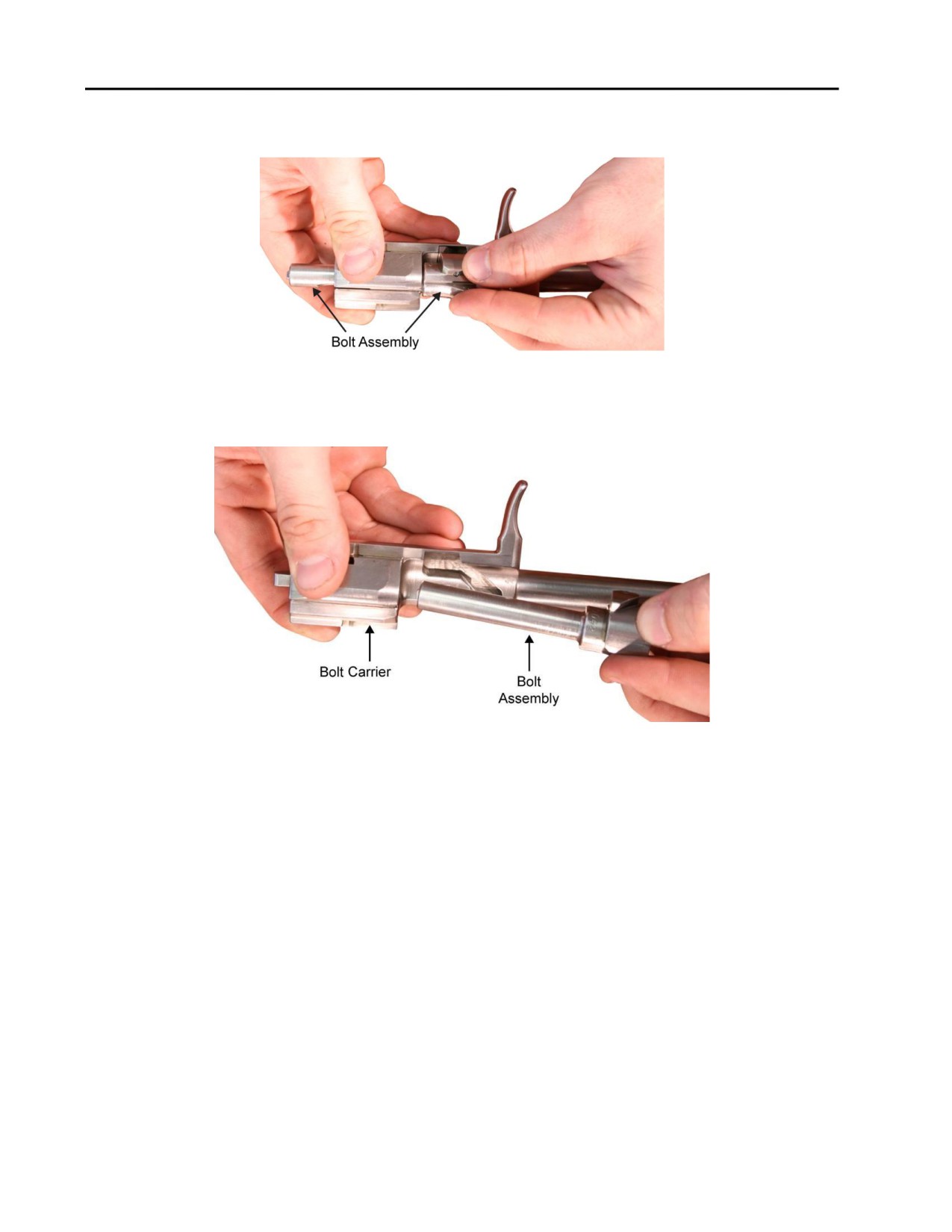
TM 8370-50007-IN/2
0011 00
2. Rotate the bolt assembly to disengage the bolt cam, located on the rounded locking lug, from the
machined cam recess of the bolt carrier. Refer to Figure 2.
Figure 2. Disengaging the Bolt Cam from the Cam Recess.
3. Pull the bolt assembly completely out of the bolt carrier. Refer to Figure 3.
Figure 3. Pulling the Bolt Assembly Out of the Bolt Carrier.
CLEANING
Clean and remove all carbon deposits. Refer to TM 8370-50007-OR/1.
INSPECTION AND REPAIR
1. Inspect the bolt carrier assembly (bolt carrier and gas piston) as follows:
a. Check the bolt carrier assembly for burrs, cracks, deformities, and defects. Remove any burrs.
Replace if damaged.
b. Check the cam recess for burrs, cracks, deformities, and defects. Remove any burrs. Replace if
damaged.
c. Clean, inspect, repair, and lubricate the bolt assembly. Refer to WP 0012 00.
LUBRICATION
For all lubrication requirements refer to TM 8370-50007-OR/1.
0011 00-2
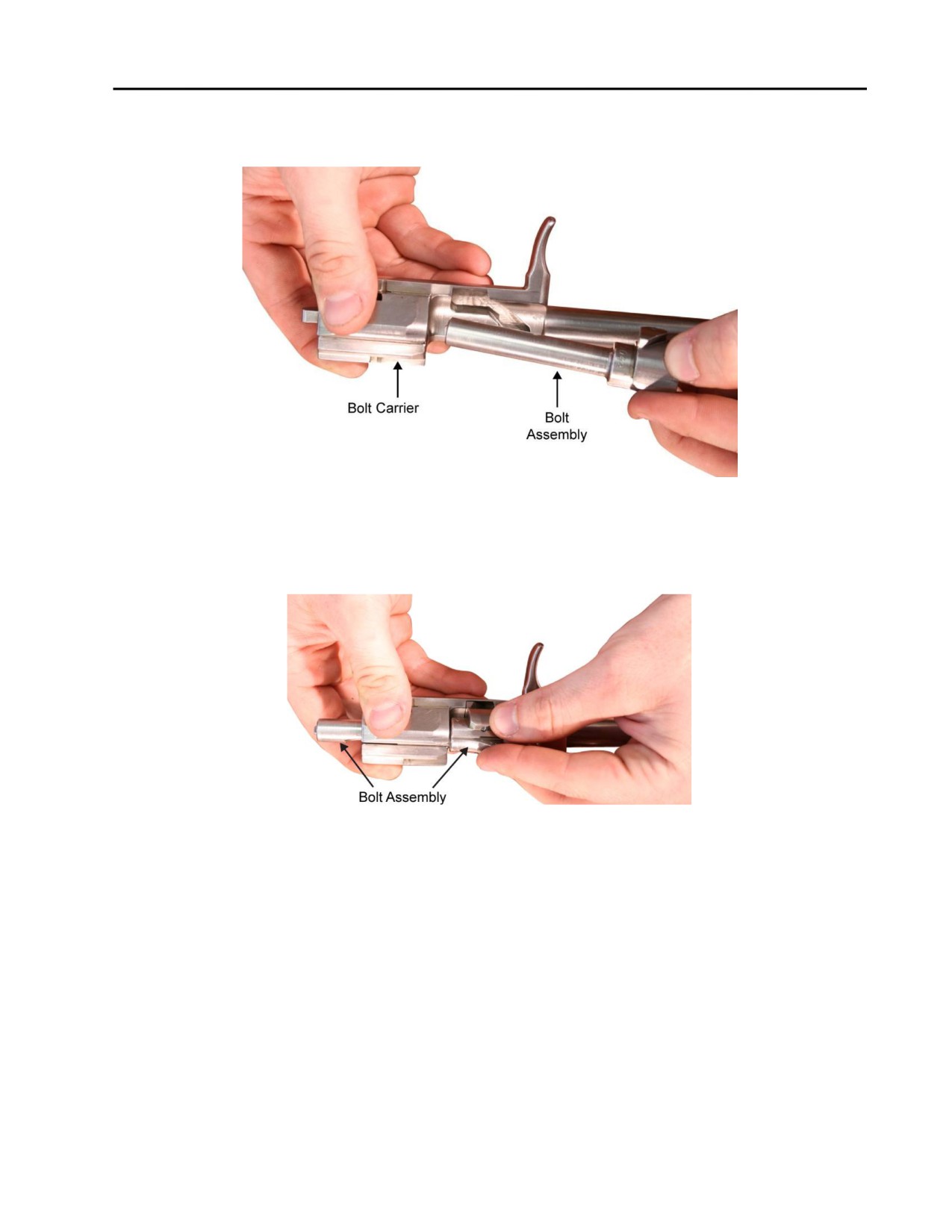
TM 8370-50007-IN/2
0011 00
REASSEMBLY
1. Push the bolt assembly into the bolt carrier. Refer to Figure 4.
Figure 4. Pushing the Bolt Assembly into the Bolt Carrier.
2. Rotate the bolt to mate the bolt cam, located on the locking lug, with the machined cam recess of the
carrier. Refer to Figure 5.
Figure 5. Mating the Bolt Cam with the Cam Recess.
0011 00-3
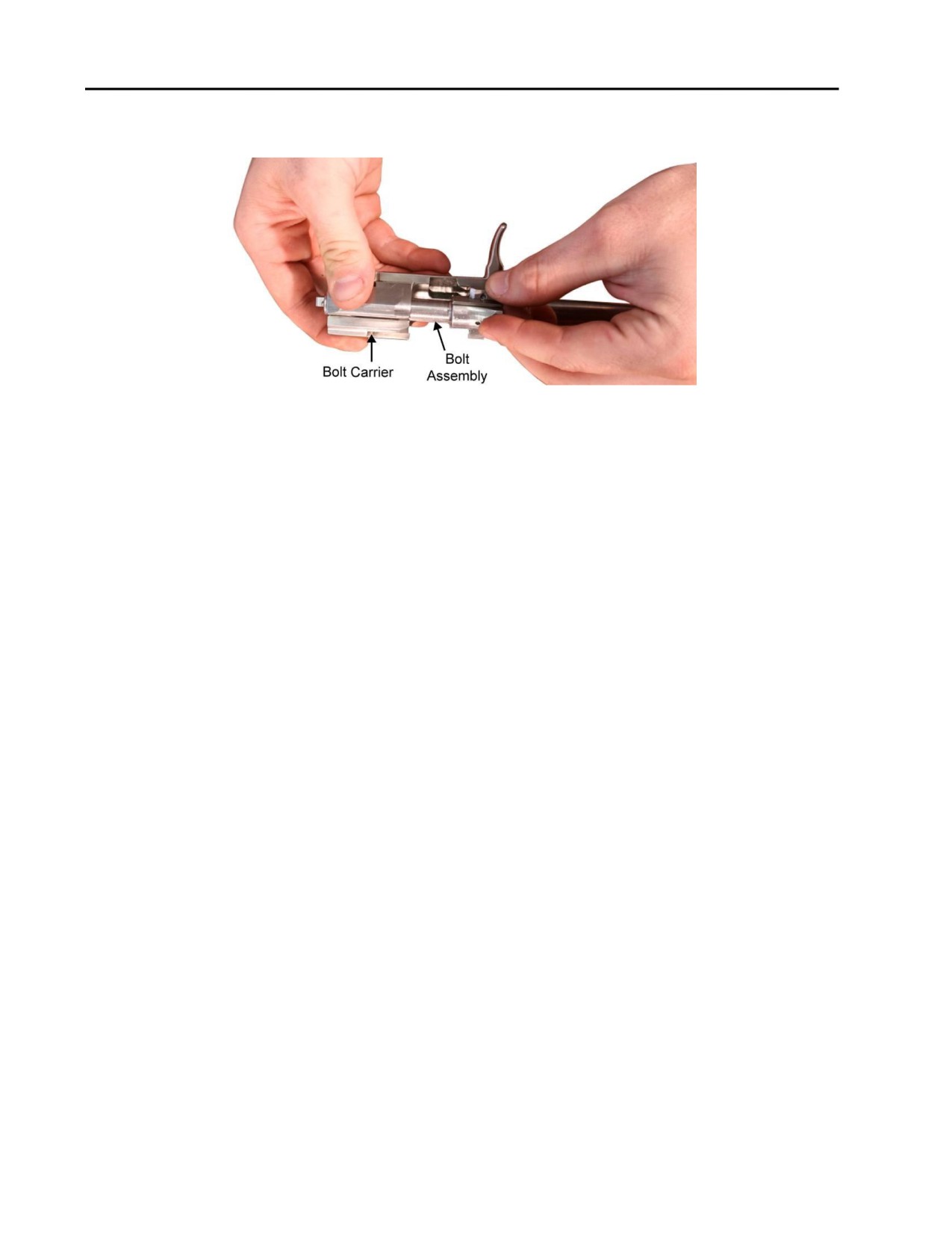
TM 8370-50007-IN/2
0011 00
3. While turning the bolt assembly, engage the bolt cam into the cam recess of the bolt carrier by pulling the
bolt assembly toward the front of the bolt carrier. Refer to Figure 6.
Figure 6. Engaging the Bolt Assembly with the Bolt Carrier.
NOTE
Ensure that the installed bolt assembly moves smoothly forward and
rearward in the bolt carrier.
END OF WORK PACKAGE
0011 00-4
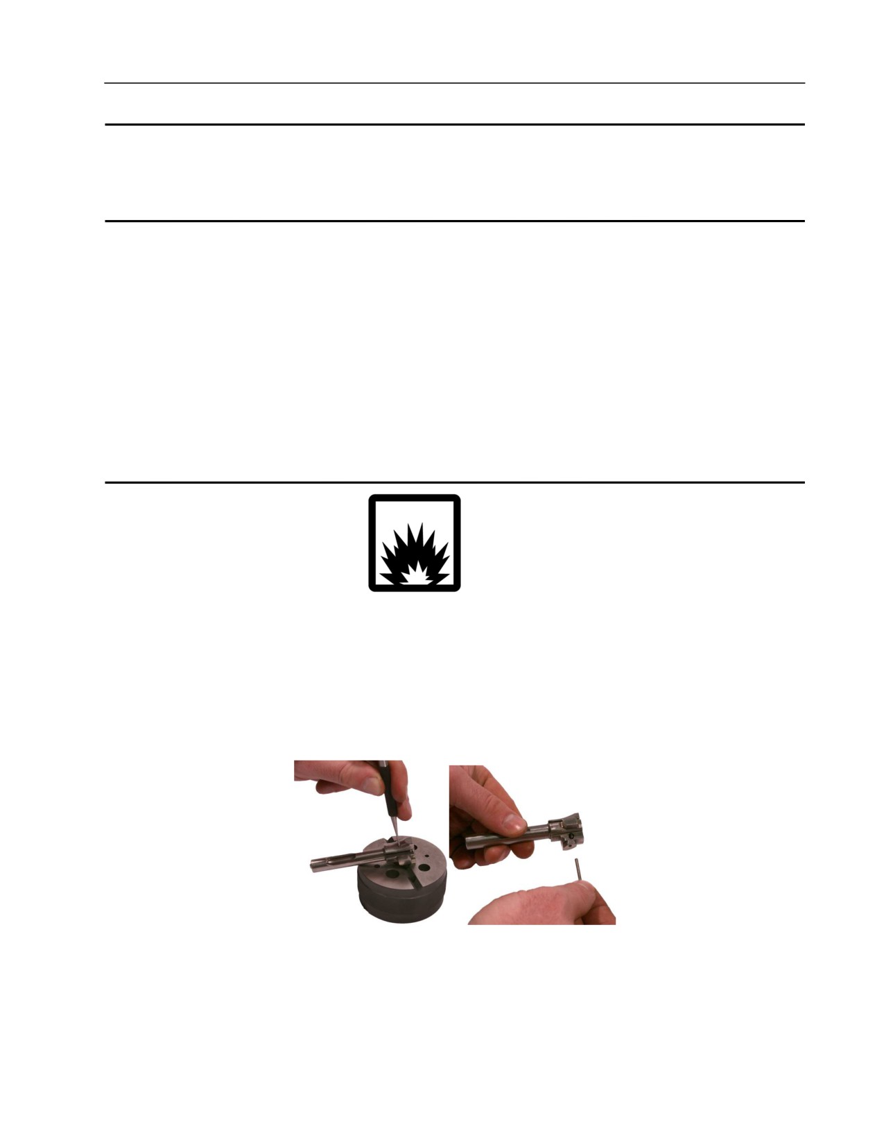
TM 8370-50007-IN/2
0012 00
BOLT ASSEMBLY
THIS WORK PACKAGE DESCRIBES
Disassembly, Cleaning, Inspection and Repair, Lubrication, and Reassembly.
INITIAL SETUP
Maintenance Level
References
Organizational
TM 8370-50007-OR/1
WP 0011 00
Tools and Special Tools
WP 0021 00
WP 0025 00
E7900 tool kit
Penetrant kit
Equipment Conditions
Bolt assembly removed (WP 0011 00)
WARNING
DO NOT interchange bolt assemblies from one weapon to another without
checking for the proper headspace. Failure to follow this warning may cause
injury or death to personnel.
DISASSEMBLY
1. Using a bench block, insert a 1/16-inch punch into the firing pin retaining pin hole, on the side of the bolt
opposite the cam, to push out the firing pin retaining pin. Refer to Figure 1.
Figure 1. Removing the Firing Pin Retaining Pin.
0012 00-1
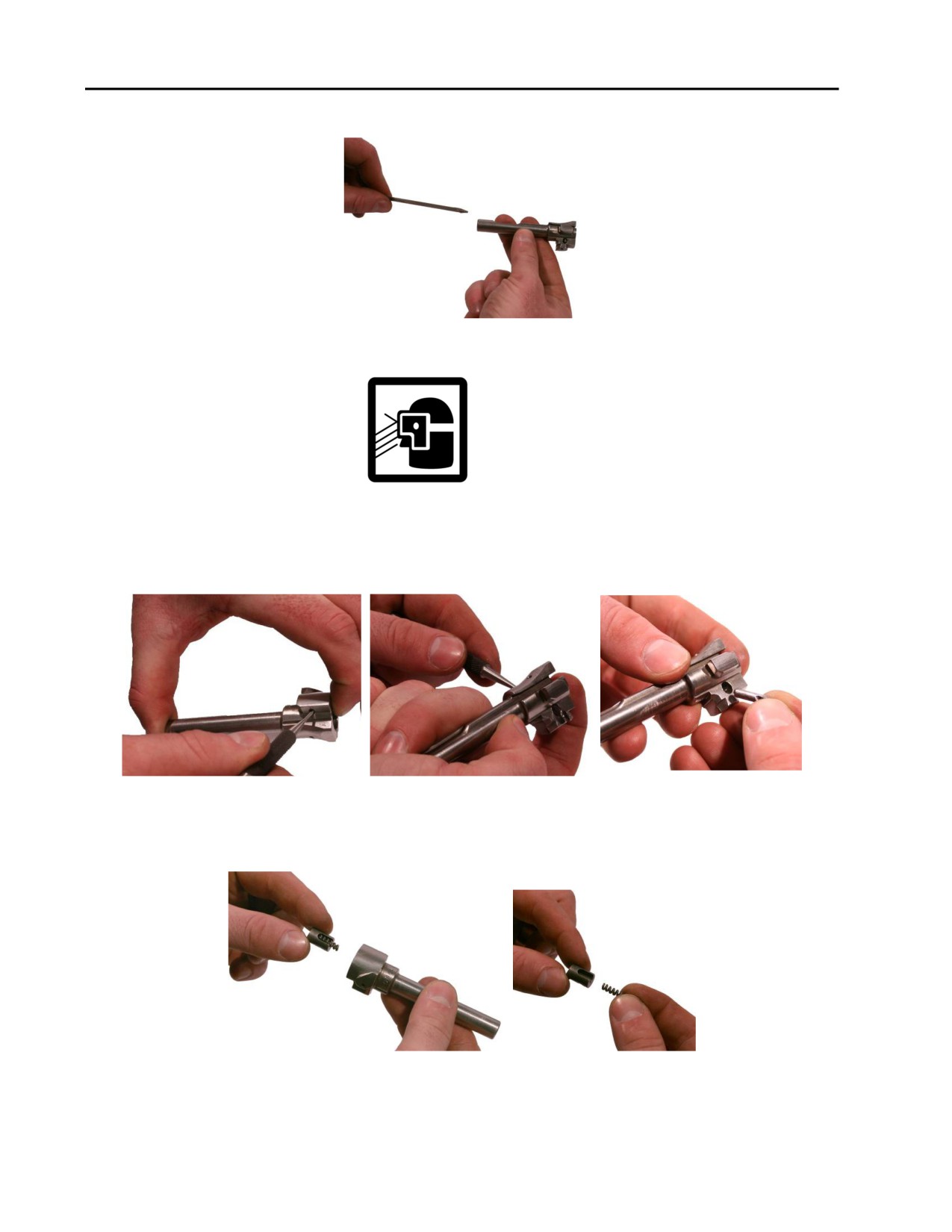
TM 8370-50007-IN/2
0012 00
2. Remove the firing pin from the bolt. Refer to Figure 2.
Figure 2. Removing the Firing Pin.
WARNING
The grooved extractor retaining pin and extractor are under spring tension.
3. While maintaining pressure on the extractor to relieve the spring tension, use a 1/16-inch punch to remove
the grooved extractor retaining pin. Refer to Figure 3.
Figure 3. Removing the Grooved Extractor Retaining Pin.
4. Remove the extractor, and extractor spring. Refer to Figure 4.
Figure 4. Removing the Extractor and Extractor Spring.
0012 00-2
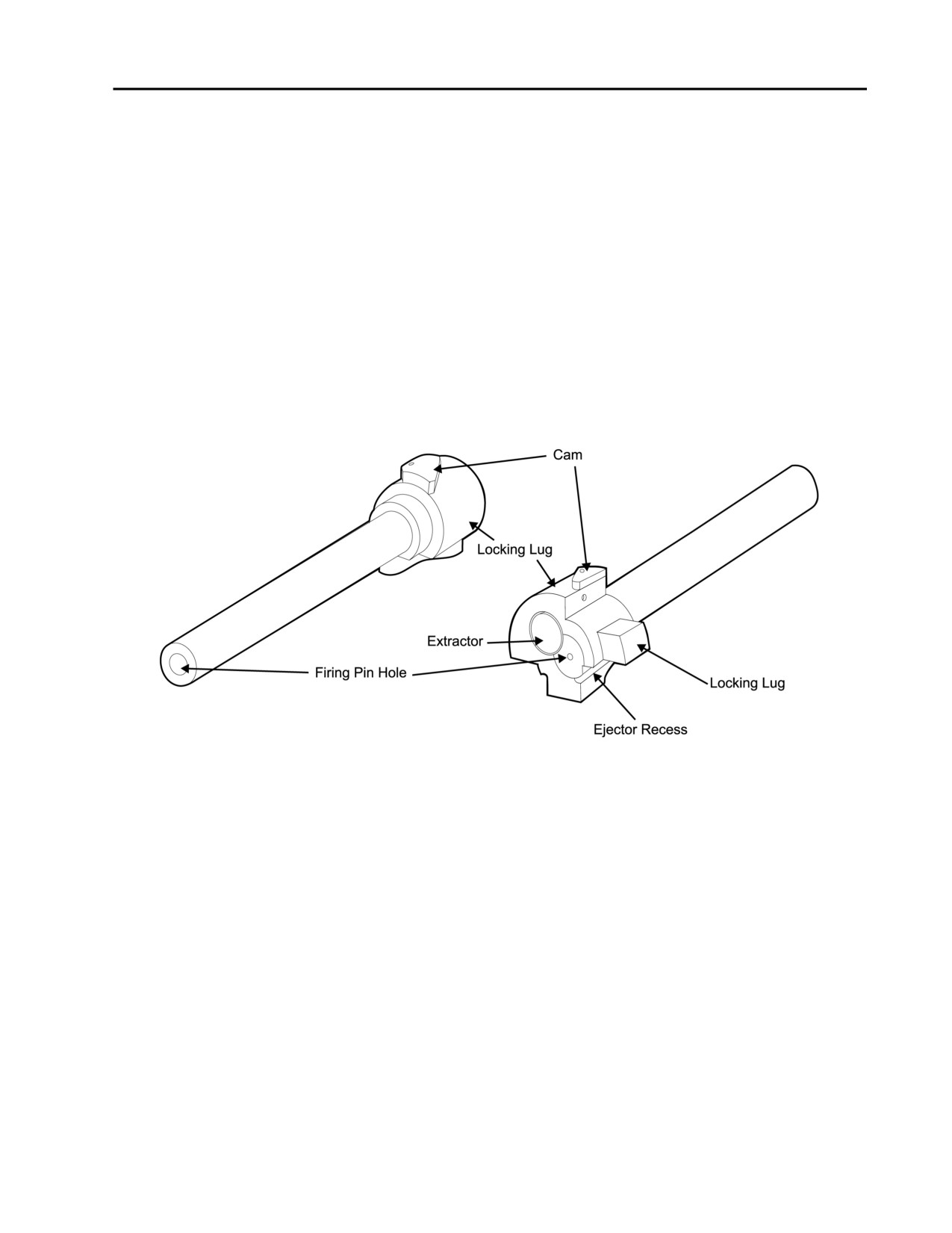
TM 8370-50007-IN/2
0012 00
CLEANING
Clean and remove all carbon deposits. Refer to TM 8370-50007-OR/1.
INSPECTION AND REPAIR
1. Check the firing pin retaining pin for bends and breaks. Replace the firing pin retaining pin if damaged.
2. Check the firing pin for bends and breaks. Replace the firing pin if damaged.
3. Check the extractor for burrs, chips, and cracks. Replace the extractor if damaged.
4. Check the extractor spring for spring tension, bends, or breaks. Replace the extractor spring if damaged.
5. Check the grooved extractor retaining pin for bends or breaks. Replace the grooved extractor retaining pin
if damaged.
6. Inspect the bolt as follows (refer to Figure 5):
Figure 5. Opposite Views of the Bolt.
a. Check the bolt for pits, burrs, and wear as follows:
(1) If the bolt face has a cluster of pits that are tightly grouped or touching and cover an area
approximately 1/8-inch across or larger, reject and replace the bolt.
(2) The bolt can contain individual or scattered pits and not be rejected.
(3) If the bolt face contains pits that extend into the firing pin hole, gage the bolt with the plain plug
“no go” gage. Refer to WP 0021 00. Replace if defective.
(4) Machine tool marks (rings, grooves, or ridges) on the bolt face less than approximately
0.010-inch are acceptable.
b. Check for cracks in the bolt. Use the penetrant kit to check for cracks in the bolt as follows:
(1) Clean the area to be inspected to ensure that it is free of dirt, grit, and grease by spraying a small
amount of remover on the area to be inspected. Let it dry, and then wipe the area off with a rag.
0012 00-3
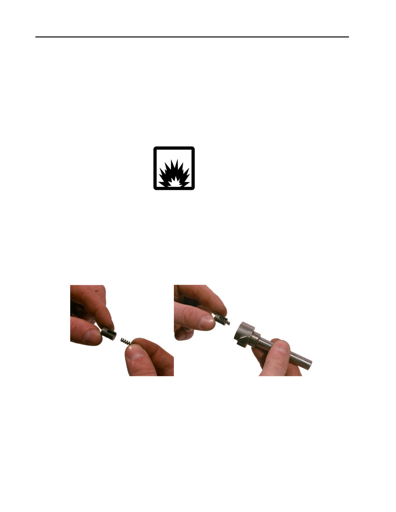
TM 8370-50007-IN/2
0012 00
(2) Spray penetrant (enough to wet the area) on the area of the bolt to be inspected.
(3) Spray developer over the area covered in penetrant, and let it sit for five to ten seconds. A crack
will be indicated by a change in color where the crack is located. If cracks appear, the
component is unserviceable and must be replaced.
(4) Pay close attention to the area where the locking lugs meet the body.
(5) If there are no cracks, spray remover on the area covered in developer, let it dry, and then wipe it
with a rag.
(6) Oil the area to prevent corrosion.
WARNING
If the bolt is replaced, perform head space gaging. Refer to WP 0021 00.
(7) Replace the bolt if damaged.
LUBRICATION
For all lubrication requirements, refer to TM 8370-50007-OR/1.
REASSEMBLY
1. Install the extractor spring into the extractor and install them into the bolt. Refer to Figure 6.
Figure 6. Installing Extractor and Extractor Spring.
0012 00-4
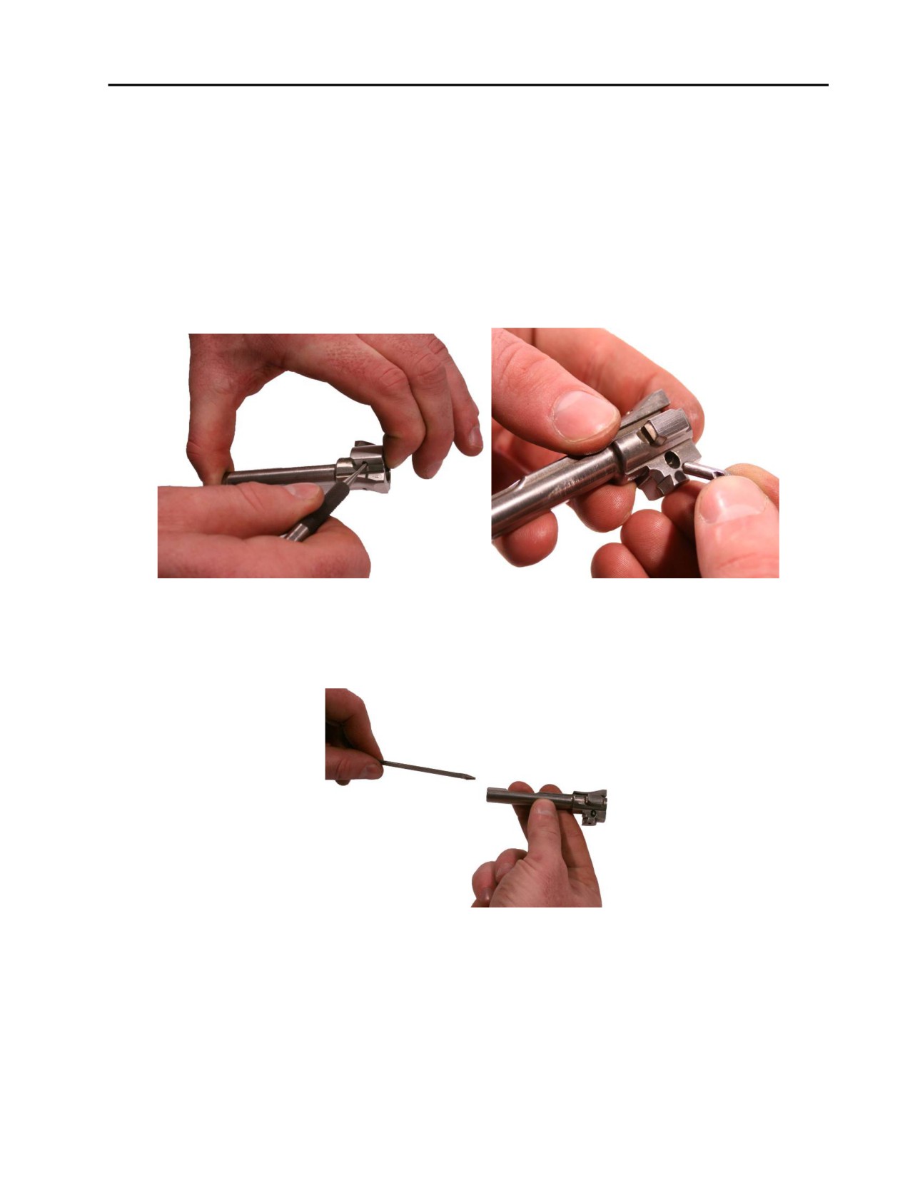
TM 8370-50007-IN/2
0012 00
CAUTION
Ensure the groove in the grooved extractor retaining pin is aligned with the
firing pin retaining pin hole BEFORE inserting the firing pin retaining pin.
Failure to do so may cause the firing pin retaining pin to lodge in the bolt
permanently.
2. Maintaining pressure on the extractor to relieve spring tension, insert a 1/16-inch punch into the SMALL
side of the extractor retaining pin hole in order to align the slot in the extractor with the grooved extractor
retaining pin hole. Install the grooved extractor retaining pin into the LARGE side of the grooved
extractor retaining pin hole (next to the bolt cam). Ensure that the grooved side of the pin is on the
LARGE side of the pin hole. Ensure it is at least flush. Refer to Figure 7.
Figure 7. Installing the Grooved Extractor Retaining Pin.
3. Install the firing pin into the bolt. Ensure the flat side of the firing pin is facing the small, squared locking
lug. Refer to Figure 8.
Figure 8. Installing the Firing Pin.
0012 00-5
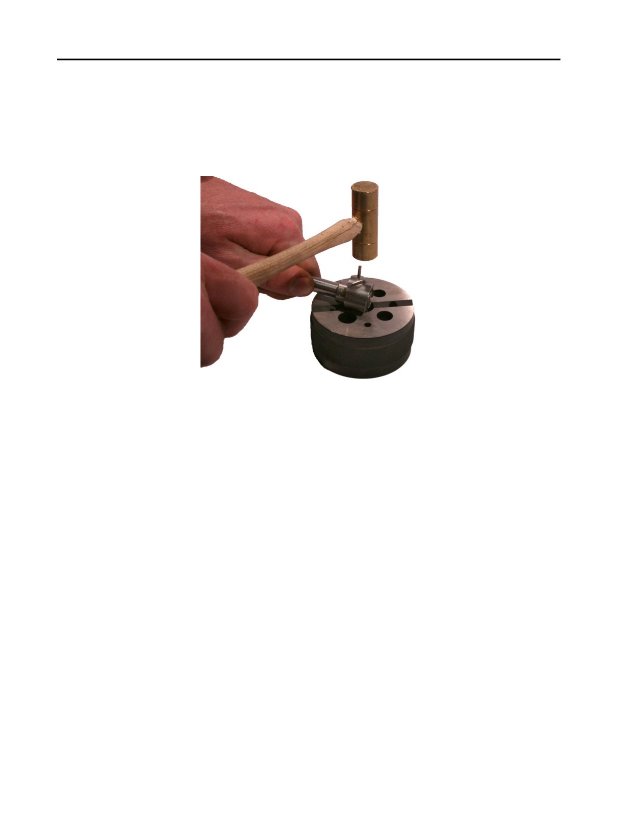
TM 8370-50007-IN/2
0012 00
4. Align the groove in the end of the grooved extractor retaining pin with the firing pin retaining pin hole.
NOTE
The firing pin may turn while installing the firing pin retaining pin. Ensure
that the flat side of the firing pin is facing the small, squared locking lug.
5. Using a hammer, lightly tap in the firing pin retaining pin until it is flush. Refer to Figure 9.
Figure 9. Installing the Firing Pin Retaining Pin.
END OF WORK PACKAGE
0012 00-6
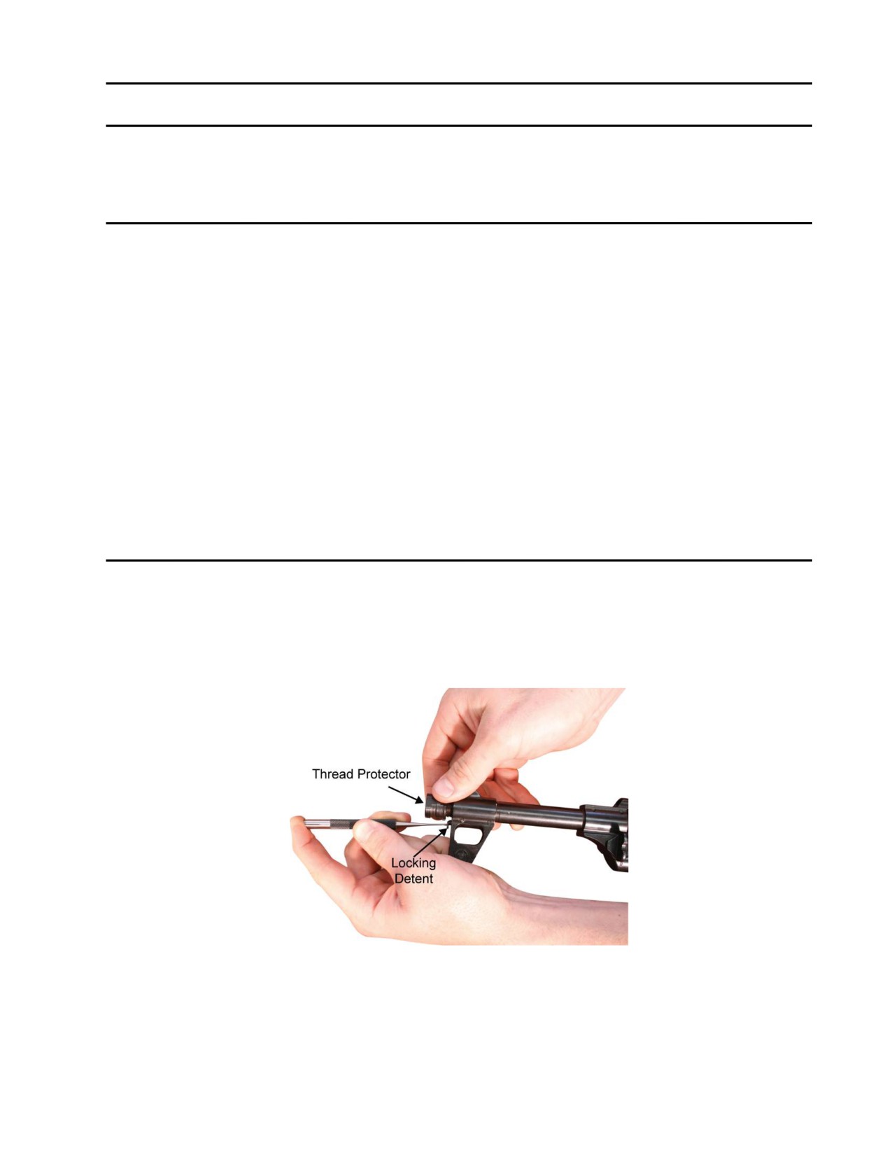
TM 8370-50007-IN/2
0013 00
RECEIVER ASSEMBLY
THIS WORK PACKAGE DESCRIBES
Disassembly, Cleaning, Inspection and Repair, Lubrication, and Reassembly.
INITIAL SETUP
Maintenance Level
References
Organizational
WP 0009 00
WP 0010 00
Tools and Special Tools
WP 0011 00
WP 0014 00
WP 0015 00
E7900 tool kit
WP 0022 00
Front sight adjustment tool
WP 0025 00
Combination tool
TM 8370-50007-OR/1.
Equipment Conditions
Weapon field stripped (WP 0010 00)
DISASSEMBLY
1. Muzzle and Front Sight.
a. Remove the thread protector from the muzzle of the barrel by holding down the locking detent with a
punch and unscrewing the thread protector until it comes off. Refer to Figure 1.
Figure 1. Depressing the Locking Detent and Removing the Thread Protector.
0013 00-1
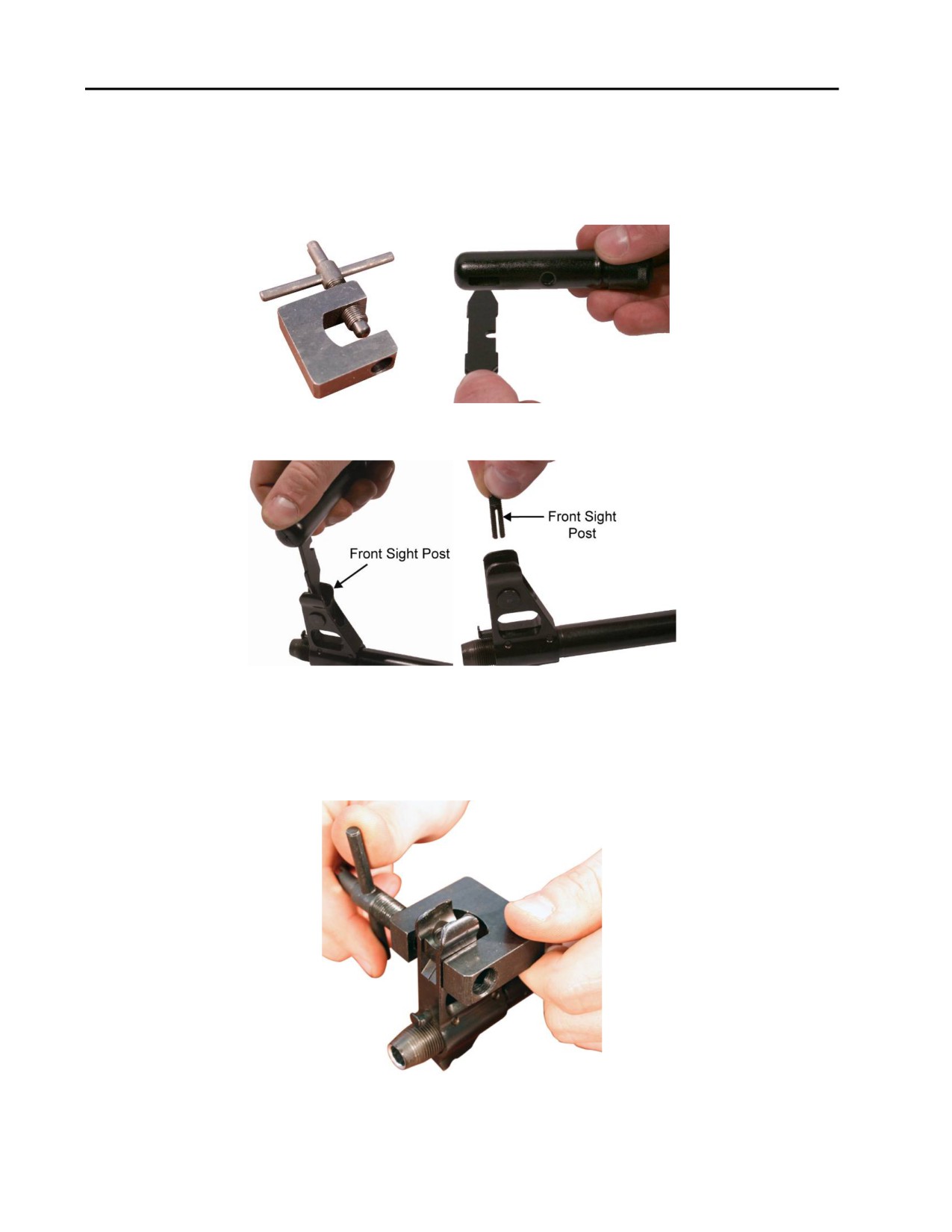
TM 8370-50007-IN/2
0013 00
NOTE
The M249 front sight tool can also be used for working on the front sight.
b. Use the front sight adjustment tool or the combination tool (refer to Figure 2) to remove the front
sight post. Refer to Figure 3.
Figure 2. Front Sight Adjustment Tool (left) and Combination Tool (right).
Figure 3. Removing the Front Sight Post.
c. Use the front sight adjustment tool to remove the windage drum. Place the ends of the clamp on either
side of the windage drum and turn the handle to push the drum out of the front sight base and through
the hole in the front sight adjustment tool. Refer to Figure 4.
Figure 4. Removing the Windage Drum.
0013 00-2
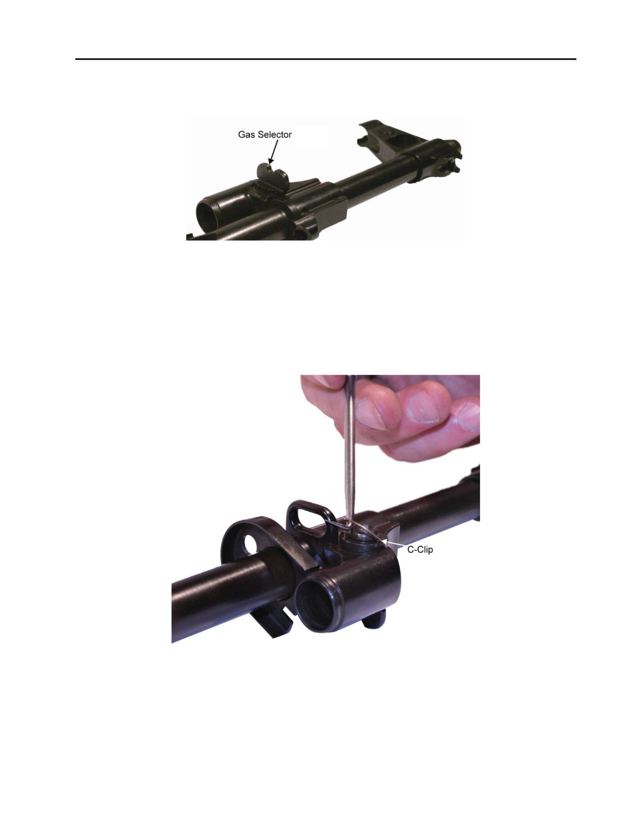
TM 8370-50007-IN/2
0013 00
2. Gas Block.
a. The gas selector must be in the UP position, indicating normal use. Refer to Figure 5.
Figure 5. Gas Selector in the UP Position.
CAUTION
The C-clip can break or deform during removal. If the C-clip becomes
broken or deformed, replace the C-clip.
b. Remove the C-clip located on the left side of the gas block by using the scraper tool and pulling away
from the open end of the C-clip. Refer to Figure 6.
Figure 6. Removing the C-Clip with the Scraper Tool.
0013 00-3
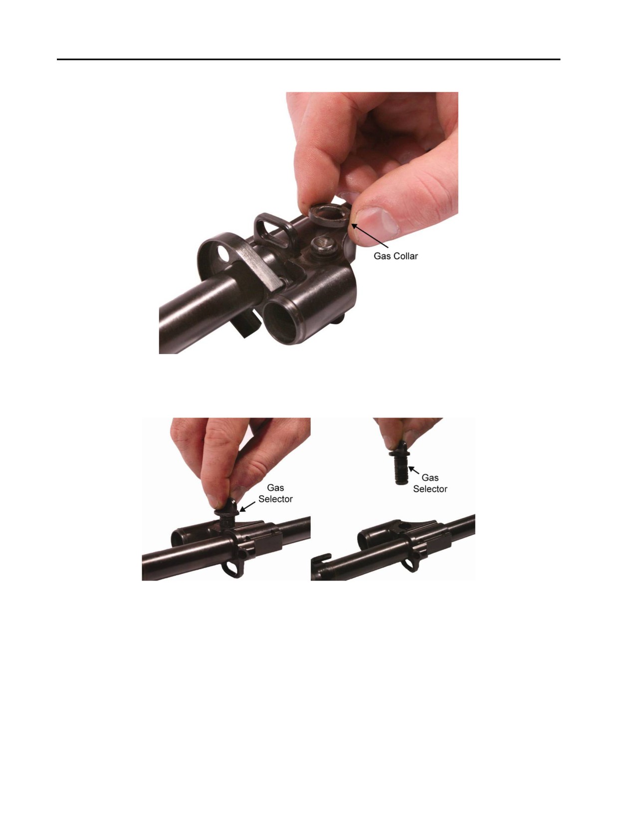
TM 8370-50007-IN/2
0013 00
c. Remove the gas collar located on the left side of the gas block. Refer to Figure 7.
Figure 7. Removing the Gas Collar.
d. Pull the gas selector out from the right side of the gas block. Refer to Figure 8.
Figure 8. Removing the Gas Selector.
0013 00-4
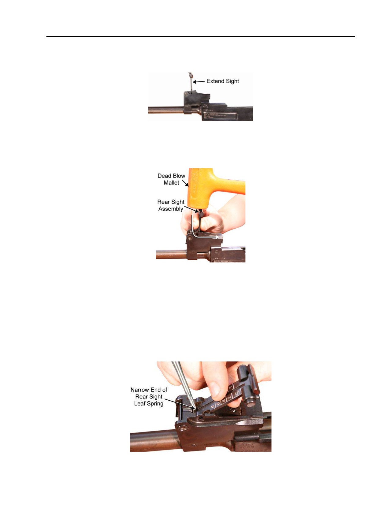
TM 8370-50007-IN/2
0013 00
3. Rear Sight.
a. Extend the rear sight. Refer to Figure 9.
Figure 9. The Rear Sight Extended.
b. While pulling the bottom of the rear sight assembly rearward, use a dead blow mallet to tap on the top
of the rear sight assembly to dislodge it. Refer to Figure 10.
Figure 10. Dislodging and Removing the Rear Sight Assembly Using a Dead Blow Mallet.
NOTE
As an alternative to steps a and b, follow step c to remove the rear sight
assembly.
c. Tilt the rear sight assembly to a 45 degree angle. While pressing down and forward on the narrow end
of the rear sight leaf spring with a punch or flat head screw driver, hold the rear sight assembly with
fingers and press down firmly to remove the rear sight assembly studs from the holes in the rear sight
base. Refer to Figure 11.
Figure 11. Dislodging the Rear Sight Assembly for Removal.
0013 00-5
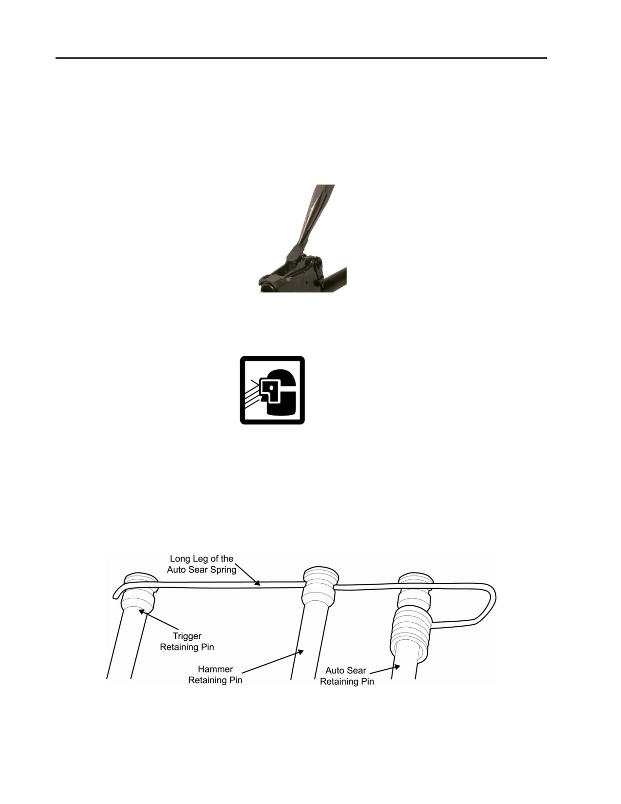
TM 8370-50007-IN/2
0013 00
d. When the rear sight assembly dislodges from the track of the rear sight base, pull it to the rear to
remove it.
NOTE
The rear sight leaf spring is staked into the rear sight base.
e. To remove the rear sight leaf spring, pull up at a 45 degree angle on the narrow, forward end with
needle-nosed pliers. Refer to Figure 12.
Figure 12. Removing the Rear Sight Leaf Spring.
4. Trigger Assembly.
WARNING
The auto sear is under spring tension. Use care when removing or installing
the auto sear.
NOTE
The long leg of the auto sear spring is set into the grooves in the heads of the
three retaining pins in the receiver in order to retain the pins in the receiver.
The auto sear spring must be lifted or lowered out of the grooves in the pins
before the pins can be removed. Refer to Figure 13.
Figure 13. Proper Installation of the Auto Sear Spring.
0013 00-6
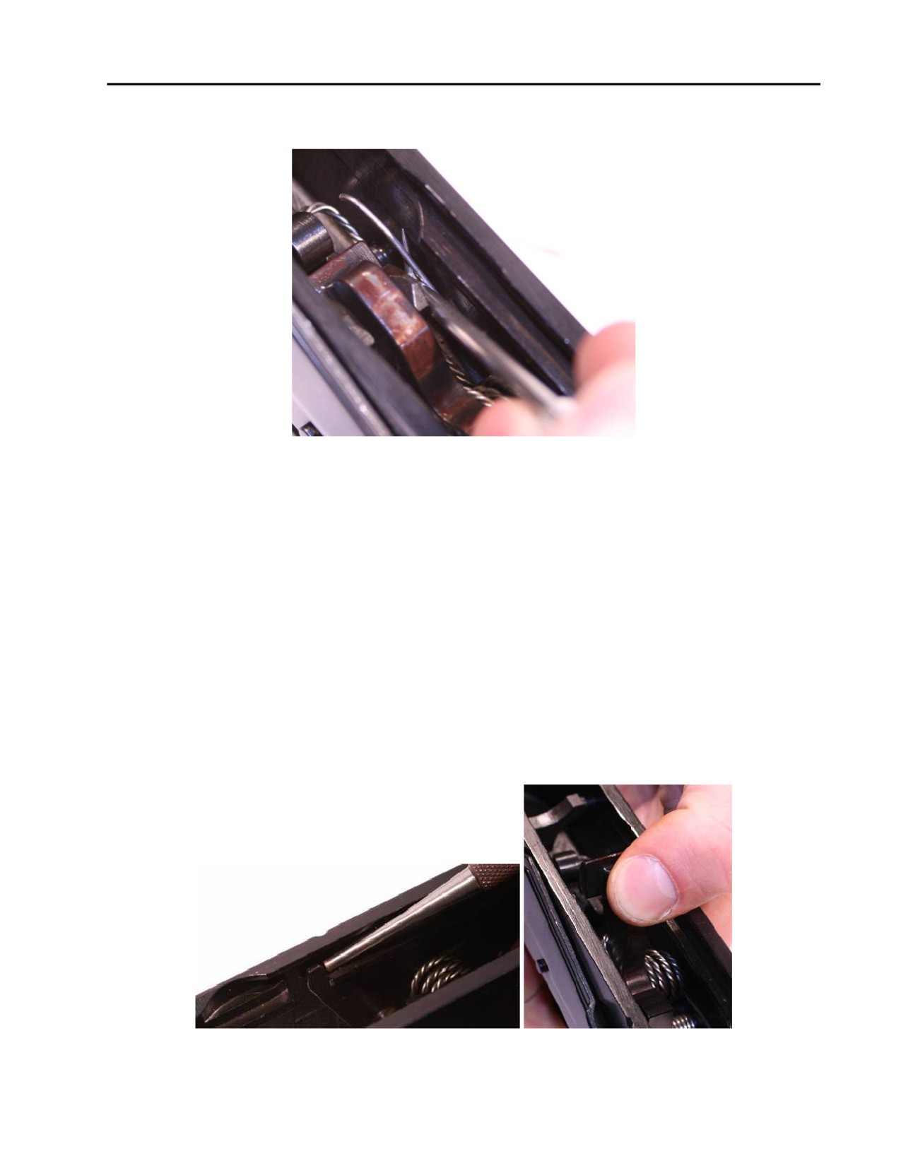
TM 8370-50007-IN/2
0013 00
a. Use a punch or the scraper tool to lift the long leg of the auto sear spring out of the groove in the head
of the trigger retaining pin. Refer to Figure 14.
Figure 14. Removing the Long Leg of the Auto Sear Spring
from the Groove in the Trigger Retaining Pin.
WARNING
After pushing down the arm of the auto sear, the hammer will be under
spring tension. Pulling the trigger will release the hammer and it will fall
forward with force.
CAUTION
Letting the hammer fall uncontrolled will damage the weapon. Ensure to
place a finger over the hammer before pulling the trigger in order to ride the
hammer forward.
b. Using a punch, push the arm of the auto sear, against the right wall of the receiver, forward until an
audible click is heard. Using a finger to ride the hammer forward, pull the trigger to release the spring
tension on the hammer. Refer to Figure 15.
Figure 15. Depressing the Arm of the Auto Sear and Riding the Hammer Forward.
0013 00-7
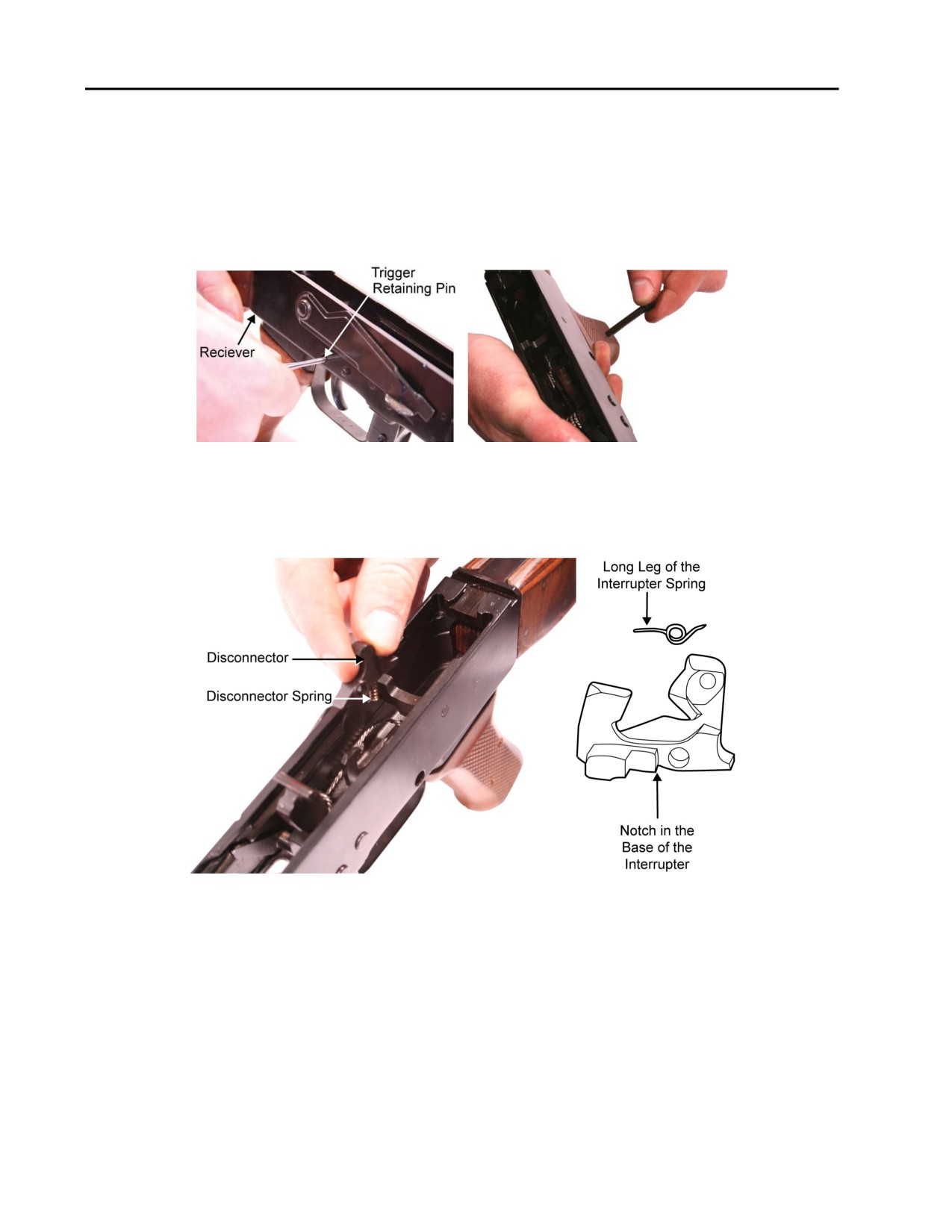
TM 8370-50007-IN/2
0013 00
CAUTION
Only moderate pressure is necessary to remove the retaining pins from the
receiver. If a retaining pin is difficult to remove, check to ensure that the
groove in the head the retaining pin is not caught on the receiver wall.
c. Use a punch to push the trigger retaining pin from the right side of the receiver and remove the pin
from the left side of the receiver. Refer to Figure 16.
Figure 16. Using a Punch to Push Out the Trigger Retaining Pin.
d. Remove the disconnector and disconnector spring. (If present, remove the interrupter and interrupter
spring.) Refer to Figure 17.
Figure 17. Removing the Disconnector and Disconnector Spring.
0013 00-8
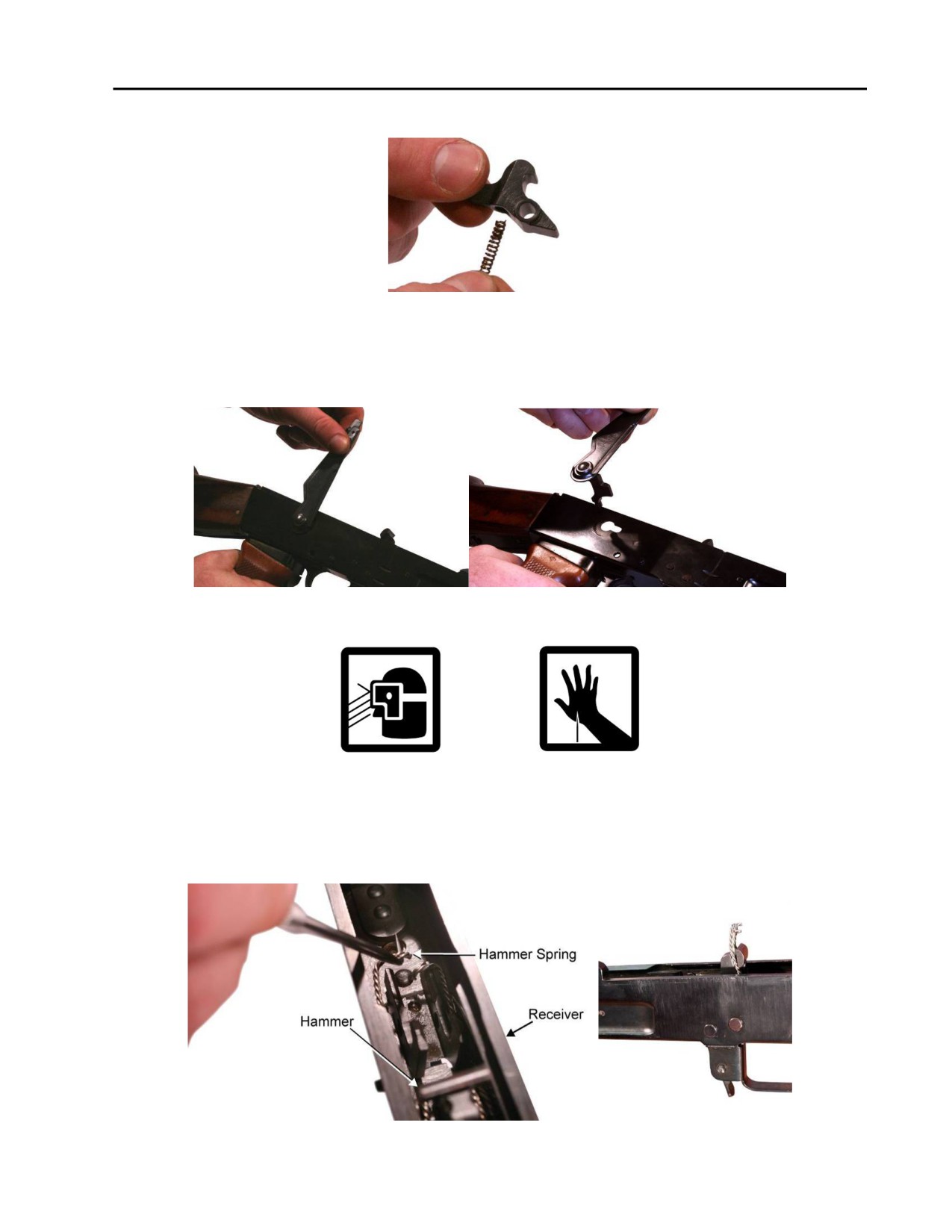
TM 8370-50007-IN/2
0013 00
e. Remove the disconnector spring from the disconnector. Refer to Figure 18.
Figure 18. Removing the Disconnector Spring from the Disconnector.
f.
Rotate the selector lever up to the 12 o’clock position and pull it out of the right side of the receiver.
Refer to Figure 19.
Figure 19. Rotating and Removing the Selector Lever.
WARNING
The hammer spring is under spring tension and the ends may be sharp
enough to puncture the skin.
g. Using needle-nosed pliers or the curved scraper tool, pull the ends of the hammer spring behind the
hammer. If necessary, secure the ends with wire. Refer to Figure 20.
Figure 20. Placing the Ends of the Hammer Spring Behind the Hammer.
0013 00-9
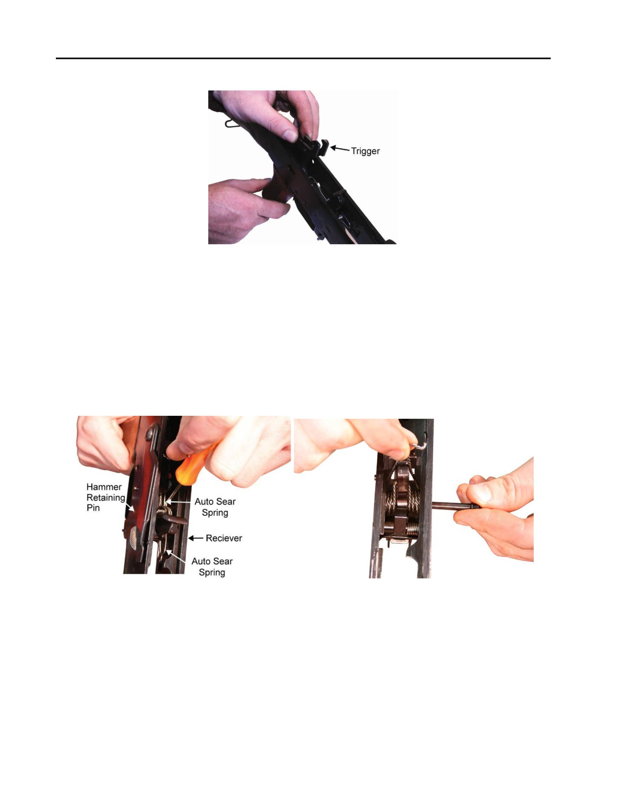
TM 8370-50007-IN/2
0013 00
h. Remove the trigger. Refer to Figure 21.
Figure 21. Removing the Trigger.
CAUTION
Only moderate pressure is necessary to remove the retaining pins from the
receiver. If a retaining pin is difficult to remove, check to ensure that the
groove in the head the retaining pin is not caught on the receiver wall.
i.
Using a punch or flat head screwdriver, apply downward pressure on the auto sear spring to push the
long leg of the auto sear spring out of the retaining groove in the hammer retaining pin. Using a
punch, push the hammer pin from the right side of the receiver and remove the pin from the left side
of the receiver. Refer to Figure 22.
Figure 22. Pushing the Long Leg of Auto Sear Spring out of the Groove in the Hammer
Retaining Pin and Removing the Hammer Retaining Pin.
0013 00-10
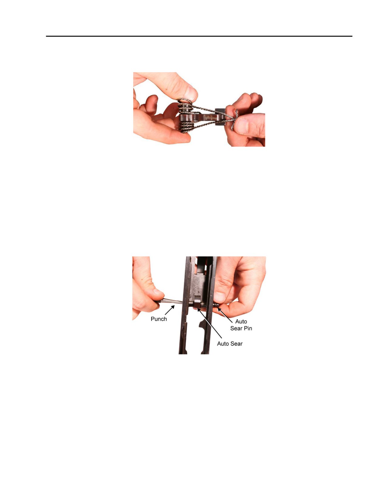
TM 8370-50007-IN/2
0013 00
j.
Rotate the hammer and hammer spring 90° as an assembly, and lift it out of the receiver. If the
hammer is difficult to remove, move it to the rear of the receiver, past the rails in the receiver, and
then remove it from the receiver. Refer to Figure 23.
Figure 23. The Hammer and Hammer Spring Removed.
k. Pull the long leg of the auto sear spring out of the groove in the auto sear retaining pin.
CAUTION
Only moderate pressure is necessary to remove the retaining pins from the
receiver. If the retaining pins are difficult to remove, check to ensure that the
grooves near the end of the retaining pins are not caught on the receiver wall.
l.
Maintaining pressure on the auto sear spring, use a punch to push the auto sear retaining pin from the
right side of the receiver and remove the pin from the left side of the receiver. Refer to Figure 24.
Figure 24. Removing the Auto Sear Retaining Pin.
0013 00-11
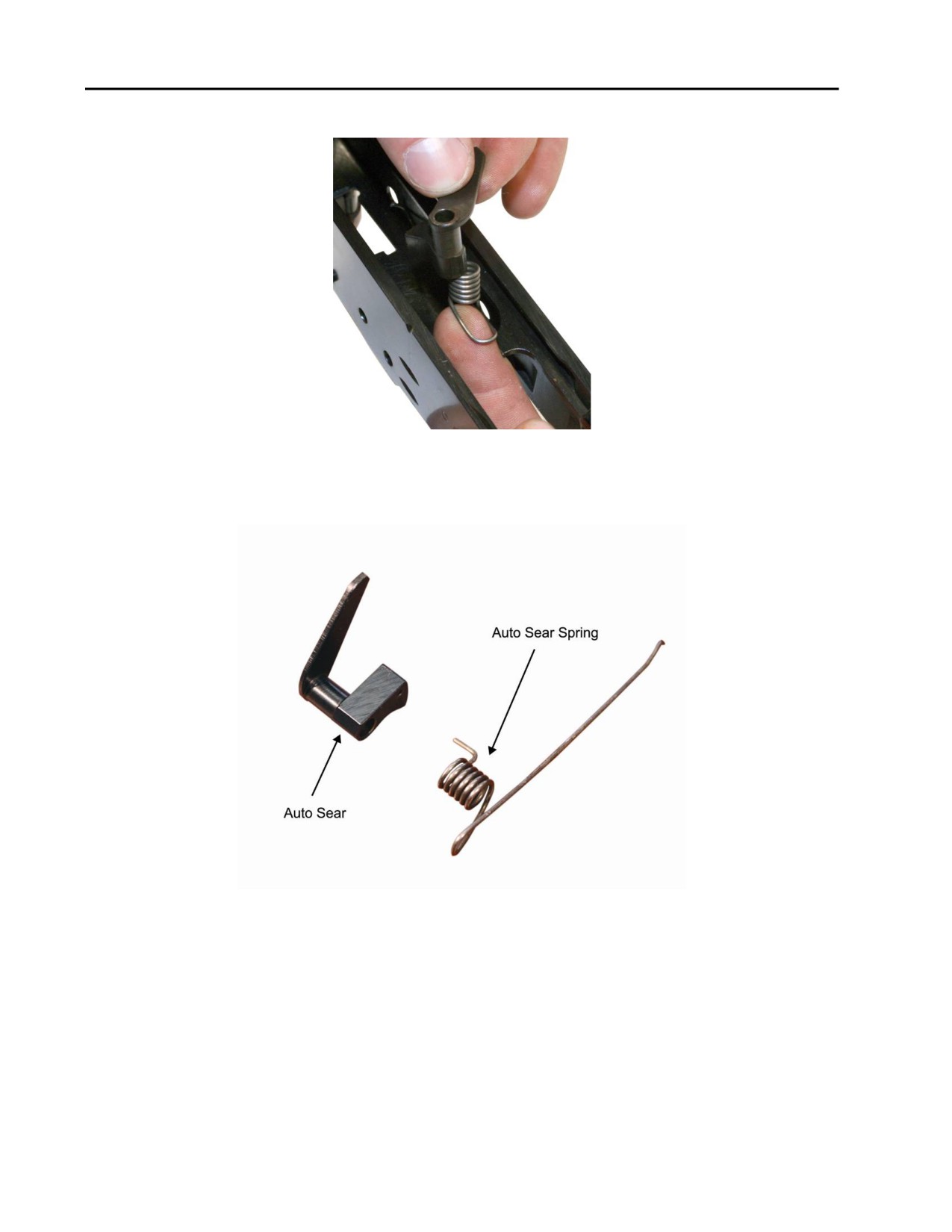
TM 8370-50007-IN/2
0013 00
m. Remove the auto sear and auto sear spring from the receiver. Refer to Figure 25.
Figure 25. Removing the Auto Sear and Auto Sear Spring from the Receiver.
n. Remove the auto sear spring from the auto sear. Refer to Figure 26.
Figure 26. The Auto Sear Spring Removed from the Auto Sear.
0013 00-12
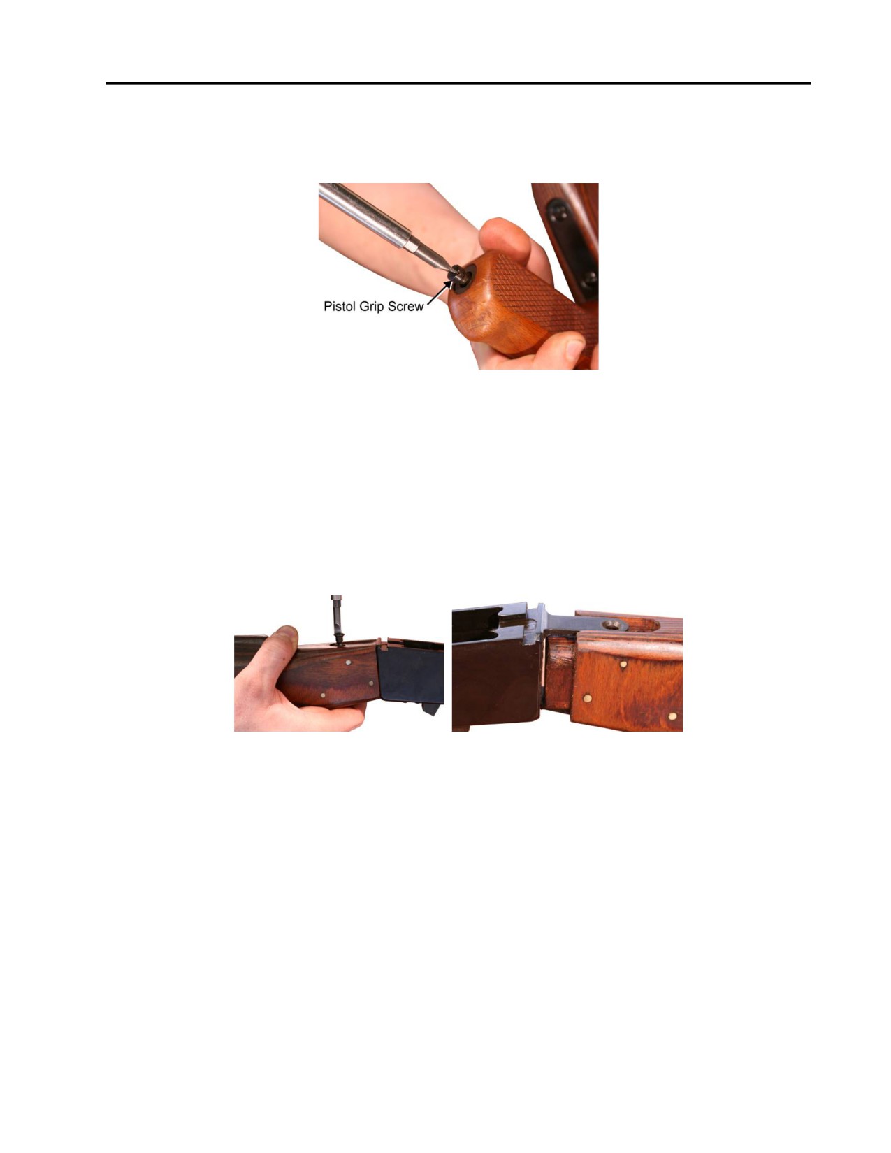
TM 8370-50007-IN/2
0013 00
5. Pistol Grip.
a. Using a flat head screwdriver, remove the pistol grip screw from the bottom of the pistol grip. Refer
to Figure 27.
Figure 27. Removing the Pistol Grip Screw.
NOTE
The pistol grip block, if present, is removed through the top of the receiver.
b. Remove the pistol grip and pistol grip screw mounting block (if present) from the weapon.
6. Fixed Buttstock. Using a flat head screwdriver, remove the top buttstock screw and the two bottom
buttstock screws located at the front of the fixed buttstock near the receiver. Pull the fixed buttstock to the
rear and remove the fixed buttstock from the receiver. Refer to Figure 28.
Figure 28. Removing Buttstock Screws and Pulling the Fixed Buttstock from the Receiver.
CLEANING
Clean and remove all carbon deposits from the weapon. Refer to TM 8370-50007-OR/1.
INSPECTION AND REPAIR
1. Muzzle, Front Sight, and Gas Block.
a. Check the front sight post and windage drum for cracks, bends, or distortion. Replace the front sight
post or windage drum if damaged.
b. Check the front sight base for cracks, bends, or breaks. Replace the front sight base if damaged.
c. Check the gas block for cracks, bends, or breaks. Replace the gas block if damaged.
d. Check the locking detent spring for breaks or bends. Replace the spring if damaged.
0013 00-13

TM 8370-50007-IN/2
0013 00
e. Check the locking detent for burrs, bends, or breaks. Remove the burrs. Replace the locking post if
damaged.
f.
Check the C-clip for bends, breaks, or deformities. Replace the C-clip if damaged.
g. Check the bayonet lug, located under front sight, for proper fit of bayonet. Check for burrs. Remove
any burrs.
2.
Receiver Assembly.
a. Check the receiver for cracks, burrs, or deformities. Remove any burrs. Replace if damaged.
b. Check the barrel for looseness in the receiver. Attempt to repair if loose. If beyond repair, replace the
receiver.
c. Check the ejector for cracks, burrs, or deformities. Remove any burrs. Attempt to repair if deformed.
If beyond repair, replace the receiver. If the ejector is worn so that it will no longer eject cartridges
during firing, replace the receiver.
d. Check the magazine release for spring tension. If there is no spring tension, attempt to repair.
3.
Rear Sight.
a. Check the rear sight leaf spring for breaks or deformities. Replace the rear sight leaf spring if
damaged
b. Disassemble, clean, lubricate, repair, and reassemble the rear sight assembly. Refer to WP 0014 00.
4.
Trigger Assembly.
a. Check all trigger components for excessive wear, burrs, bends, breaks, and cracks. Remove any burrs
and replace the components if damaged.
b. Check all springs for bends, breaks, flat spots, and spring tension. Replace the springs if damaged.
0013 00-14

TM 8370-50007-IN/2
0013 00
5. Fixed Buttstock.
a. Check the fixed buttstock for cracks. Up to three cracks are acceptable. No cracks are acceptable in
the critical areas (near pins or screws). Refer to Figure 29. Replace the buttstock if damaged.
Figure 29. Critical Areas of the Fixed Buttstock.
b. Check the buttstock screws for burrs. Remove the burrs. Replace the screws if damaged.
c. Disassemble, clean, lubricate, repair, and reassemble the buttplate and trap door. Refer to
WP 0015 00.
LUBRICATE
Lubricate all metal parts with CLP. Refer to WP 0009 00.
REASSEMBLY
1. Fixed Buttstock.
a. Align the fixed buttstock with the rear of the receiver. Install and secure it with the one, shorter top
buttstock screw and the two, longer bottom buttstock screws. Refer to Figure 30.
Figure 30. Aligning and Installing the Fixed Buttstock onto the Rear of the Receiver.
0013 00-15
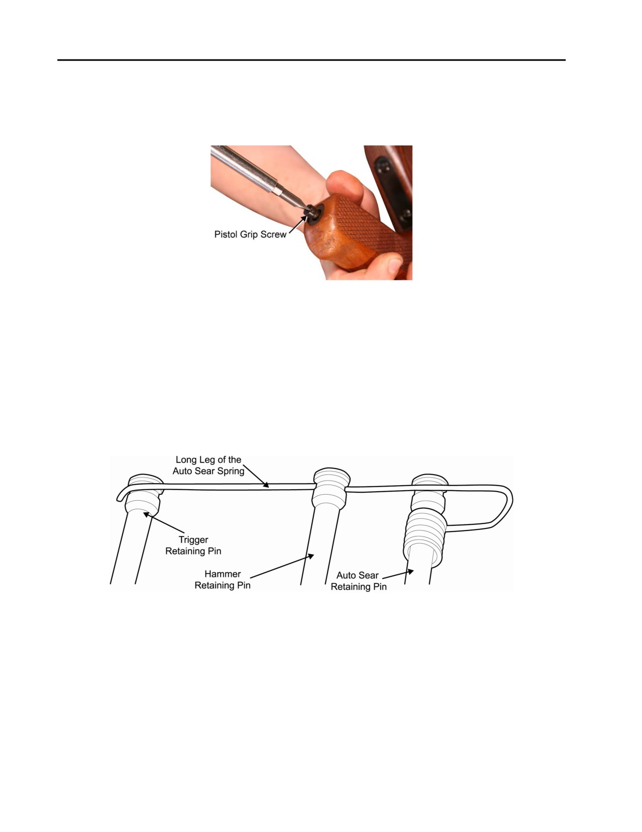
TM 8370-50007-IN/2
0013 00
2. Pistol Grip.
a. Install the pistol grip screw mounting block, if present, through the top of the receiver. Install the
pistol grip. Using a flat head screw driver, install the pistol grip screw through the pistol grip and into
the mounting block. Refer to Figure 31.
Figure 31. Installing the Pistol Grip.
b. Ensure the pistol grip is secure.
3. Trigger Assembly.
NOTE
When installing the retaining pins, ensure that the long leg of the auto sear
spring is properly installed. Refer to Figure 32. The long leg of the auto sear
spring must be properly set into the grooves in the heads of the three
retaining pins in the receiver in order to retain the pins in the receiver.
Figure 32. Proper Installation of the Long Leg of the Auto Sear Spring.
0013 00-16
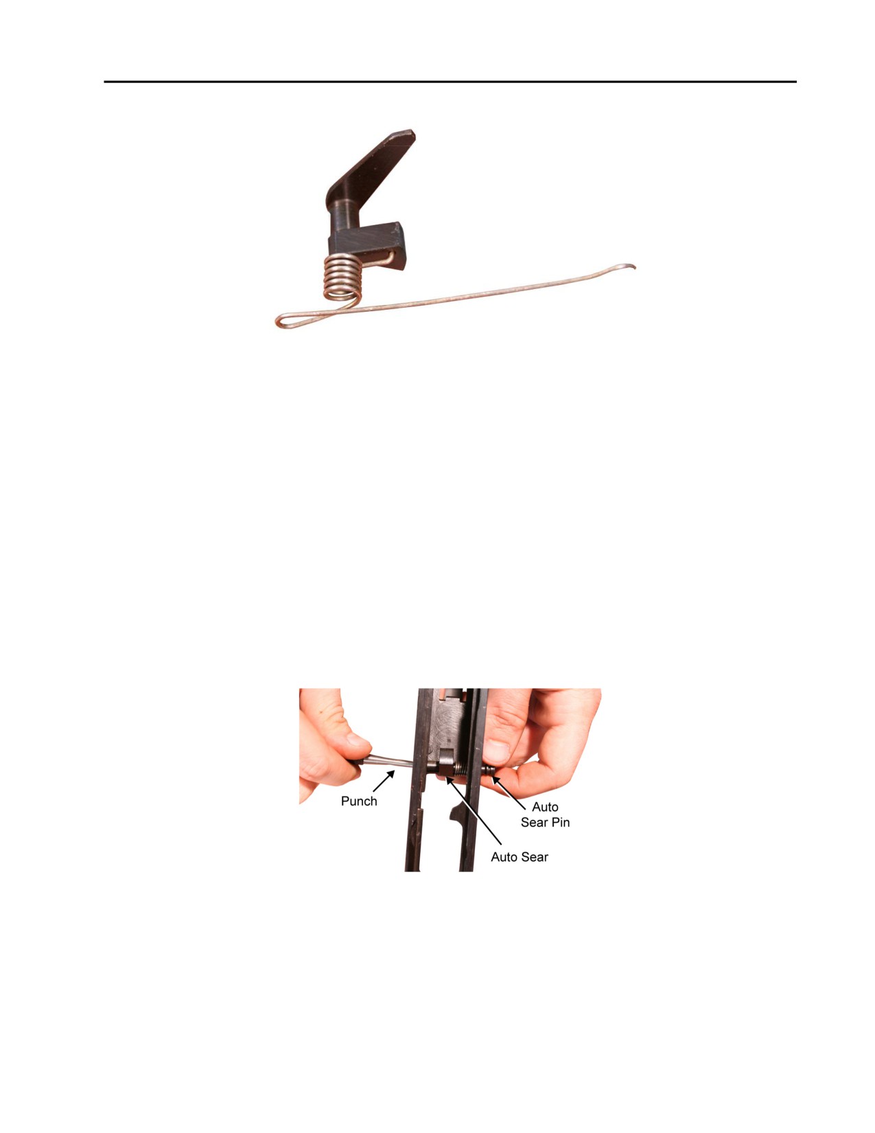
TM 8370-50007-IN/2
0013 00
a. Install the short leg of the auto sear spring in the auto sear. Refer to Figure 33.
Figure 33. The Short Leg of the Auto Sear Spring Installed in the Auto Sear.
NOTE
When installing the auto sear and auto sear spring, use a punch, inserted from
the right side of the receiver, as a slave pin to hold them in place until the
auto sear retaining pin is installed.
b. Install the auto sear assembly in the receiver. Ensure that the arm of the auto sear is against the right
side of the receiver and the long leg of the auto sear spring is against the left side of the receiver.
CAUTION
Only moderate pressure is necessary to install the retaining pins into the
receiver. If the retaining pins are difficult to install, check to ensure that the
grooves in the heads of the retaining pins are not caught on the receiver wall.
c. Insert the auto sear retaining pin from the left side of the receiver, ensuring to thread the pin through
the auto sear spring and the auto sear. Refer to Figure 34.
Figure 34. Installing the Auto Sear Retaining Pin.
0013 00-17
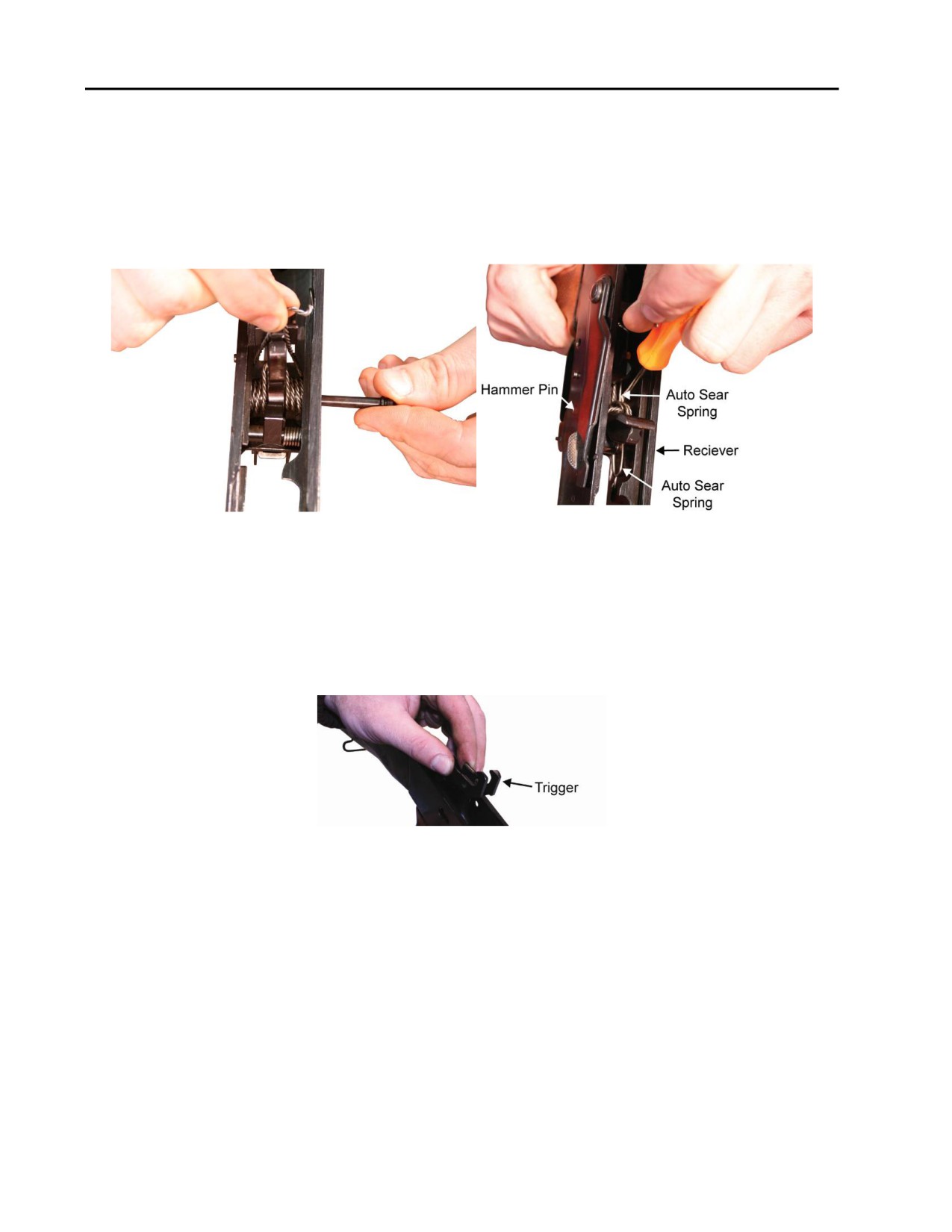
TM 8370-50007-IN/2
0013 00
NOTE
When installing the hammer assembly, ensure the wider side of the hammer
is facing the rear of the receiver. Refer to Figure 35.
d. Install the hammer assembly into the receiver, then insert the hammer retaining pin from the left side
of the receiver. Ensure that the long leg of the auto sear spring is BELOW the hammer retaining pin
and set it in the groove of the pin near the left side of the receiver. Refer to Figure 35.
Figure 35. Installing the Hammer Assembly and the Hammer Retaining Pin and Setting the
Auto Sear Spring into Groove of the Hammer Retaining Pin.
NOTE
AK-47 models without interrupters will have dual hammer hooks on the
trigger. Refer to Figure 36. In models with dual trigger hooks, the trigger
must be installed BEFORE installing the selector lever.
Figure 36. Trigger with Dual Hammer Hooks.
0013 00-18
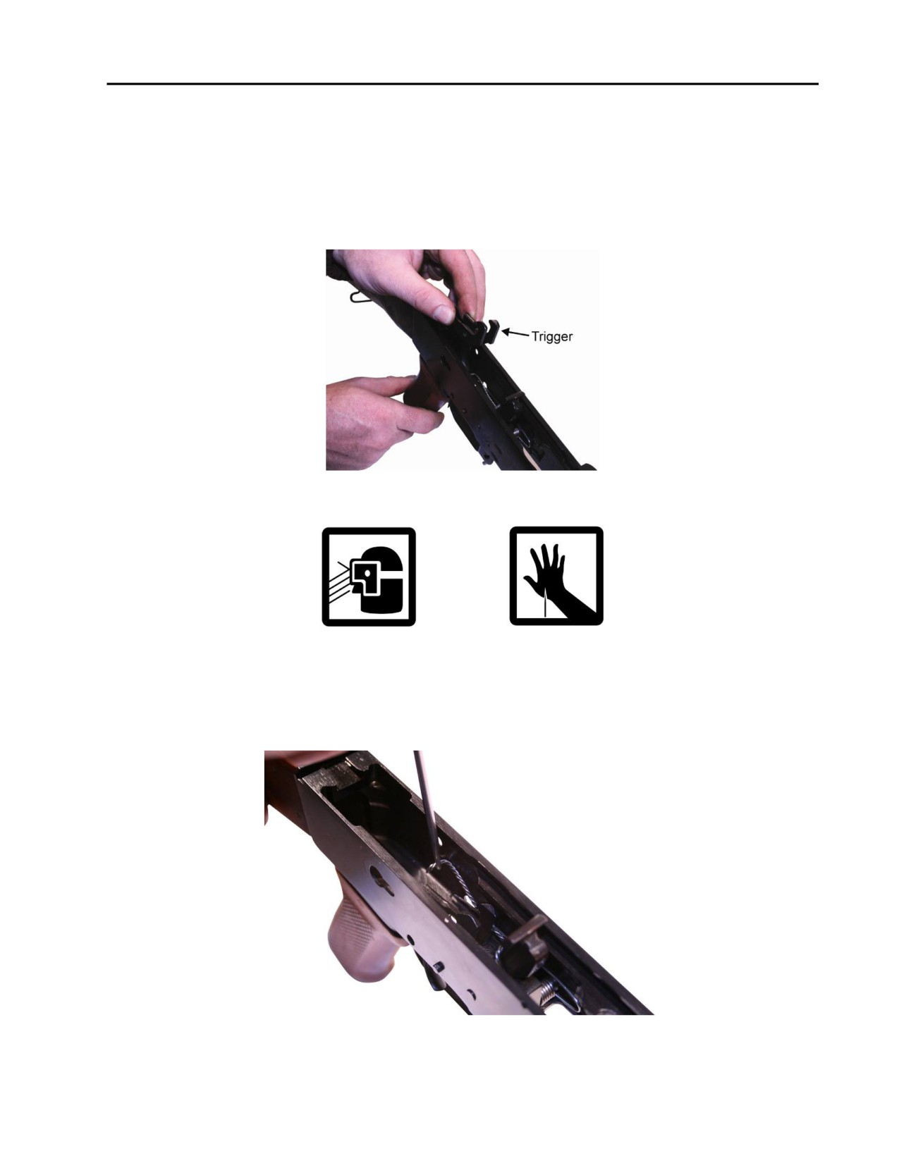
TM 8370-50007-IN/2
0013 00
NOTE
When installing the trigger and disconnector assembly, use a punch as a slave
pin. Insert the punch from the right side of the receiver and thread it through
the holes in the trigger and disconnector to hold them in place until the
trigger retaining pin is installed.
e. Install the trigger in the receiver. Refer to Figure 37.
Figure 37. Installing the Trigger.
WARNING
The hammer spring is under spring tension and the ends may be sharp
enough to puncture the skin.
f.
Remove the wire, if used, from the ends of the hammer spring and carefully lower the legs of the
hammer spring until they rest on top of the trigger. Refer to Figure 38.
Figure 38. Lowering the Hammer Spring Legs onto the Trigger.
0013 00-19
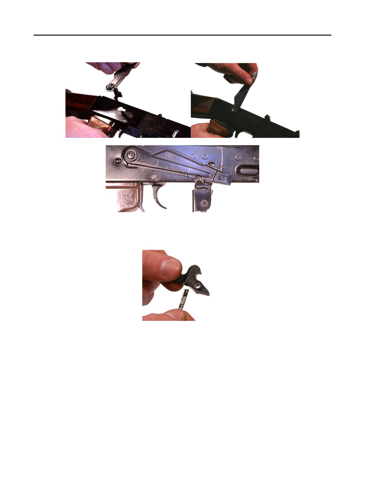
TM 8370-50007-IN/2
0013 00
g. With the selector lever in the 12 o’clock position, install it on the right side of the receiver and rotate
down to the SEMI position. Refer to Figure 39.
Figure 39. Installing the Selector Lever and Setting on SEMI.
h. Install the disconnector spring into the disconnector. Refer to Figure 40.
Figure 40. Installing the Disconnector Spring.
0013 00-20
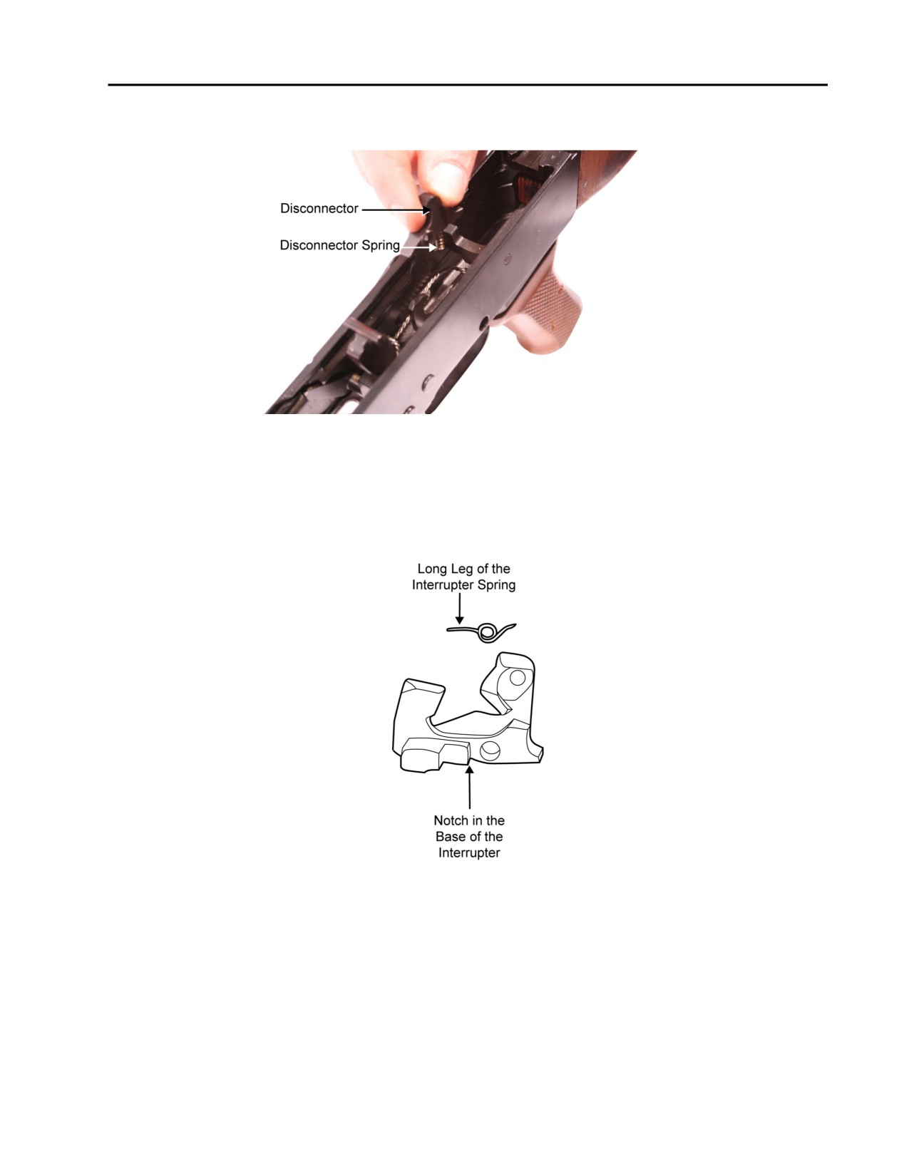
TM 8370-50007-IN/2
0013 00
i.
Install the disconnector into the trigger. Ensure that the hole in the disconnector aligns with the hole
in the trigger. Refer to Figure 41.
Figure 41. Installing the Disconnector and Disconnector Spring.
j.
If present, install the interrupter onto the trigger, ensuring that the notch in the base of the interrupter
is seated on the forward edge of the right side of the trigger. Install the interrupter spring with the
long leg of the spring pointing forward. Ensure that the hole in the base of the interrupter and the coil
of the interrupter spring are aligned with the holes in the trigger. Refer to Figure 42.
Figure 42. The Interrupter and Interrupter Spring.
0013 00-21
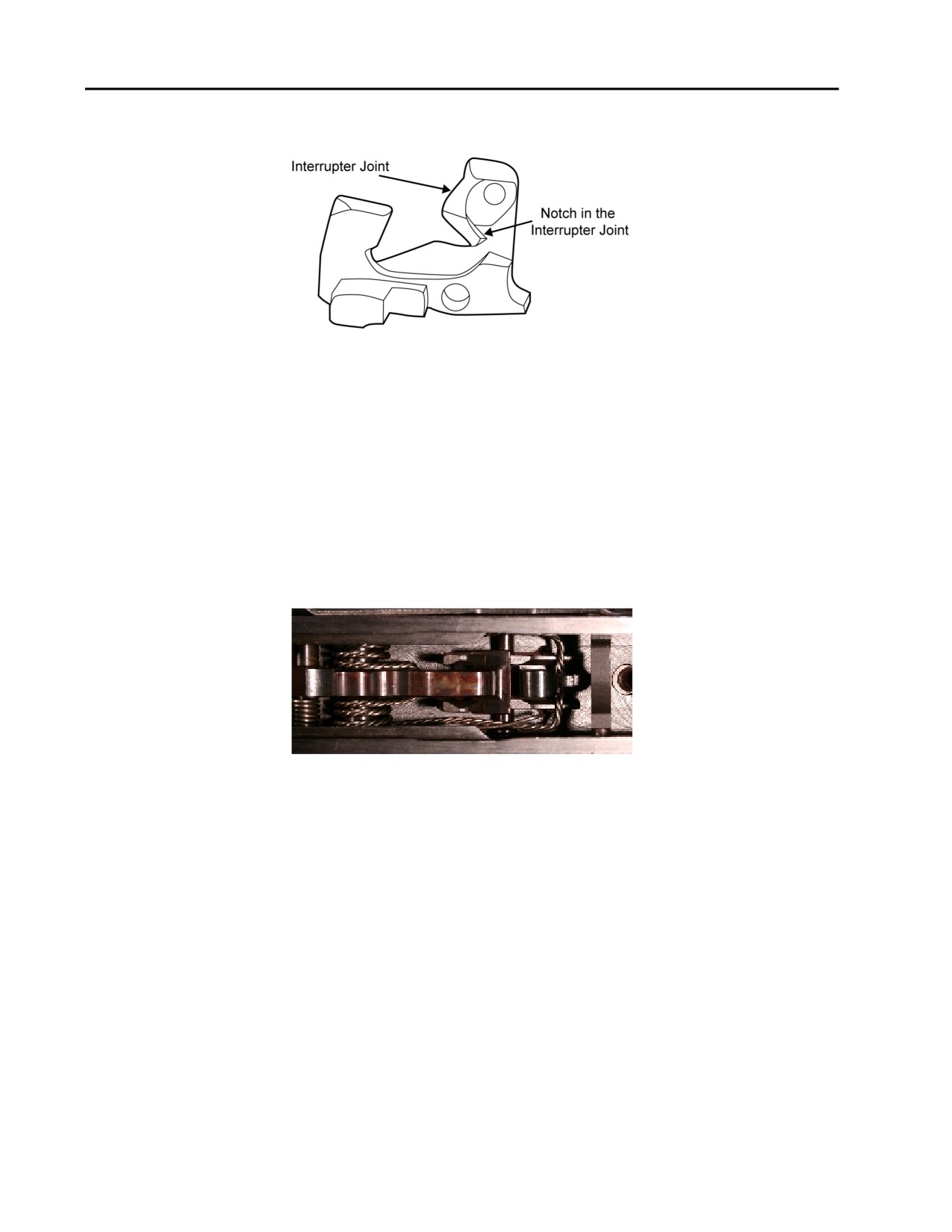
TM 8370-50007-IN/2
0013 00
k. If present, push the long leg of the interrupter spring to the rear until it seats in the notch in the
interrupter joint. Refer to Figure 43.
Figure 43. The Notch in the Interrupter Joint.
CAUTION
Only moderate pressure is necessary to install the retaining pins into the
receiver. If the retaining pins are difficult to install, check to ensure that the
grooves in the heads of the retaining pins are not caught on the receiver wall.
l.
Insert the trigger retaining pin from the left side of the receiver. Ensure to thread the pin through the
holes in the trigger and the disconnector. Ensure the long leg of the auto sear spring is on top of the
trigger retaining pin and in the groove in the head of the pin.
m. Push the hammer down until it locks in the cocked position. Refer to Figure 44.
Figure 44. The Hammer in the Cocked Position.
CAUTION
Ensure that all retaining pins are fully seated in the receiver.
0013 00-22
//////////////////////////////////////////