FM 3-20.98 Reconnaissance and Scout Platoon (AUGUST 2009) - page 6
Appendix G
Table G-7. Measurement correlations for a steel stringer
MLC 30 bridge with concrete deck
50-FOOT
40-FOOT
30-FOOT
25-FOOT
20-FOOT
SPAN
SPAN
SPAN
SPAN
SPAN
STRINGER HEIGHT x WIDTH (inches)
8-FOOT
24-1/4
24-1/8
17-3/4
16-3/4
15
STRINGER
x 9
x 9
x 6-5/8
x 6-1/2
x 5-7/8
SECTION
6-FOOT
24-1/8
24
16
15-3/4
14
STRINGER
x 9
x 7
x 8-1/2
x 6-1/8
x 6
SECTION
4-FOOT
21-1/4
18-1/4
16-3/4
15
13-3/8
STRINGER
x 8-1/4
x 7
x 6-1/2
x 5-7/8
x 5-3/8
SECTION
2-FOOT
18-1/4
16-1/4
15
14
12
STRINGER
x 7
x 7-1/8
x 5-7/8
x 5-1/2
x 5
SECTION
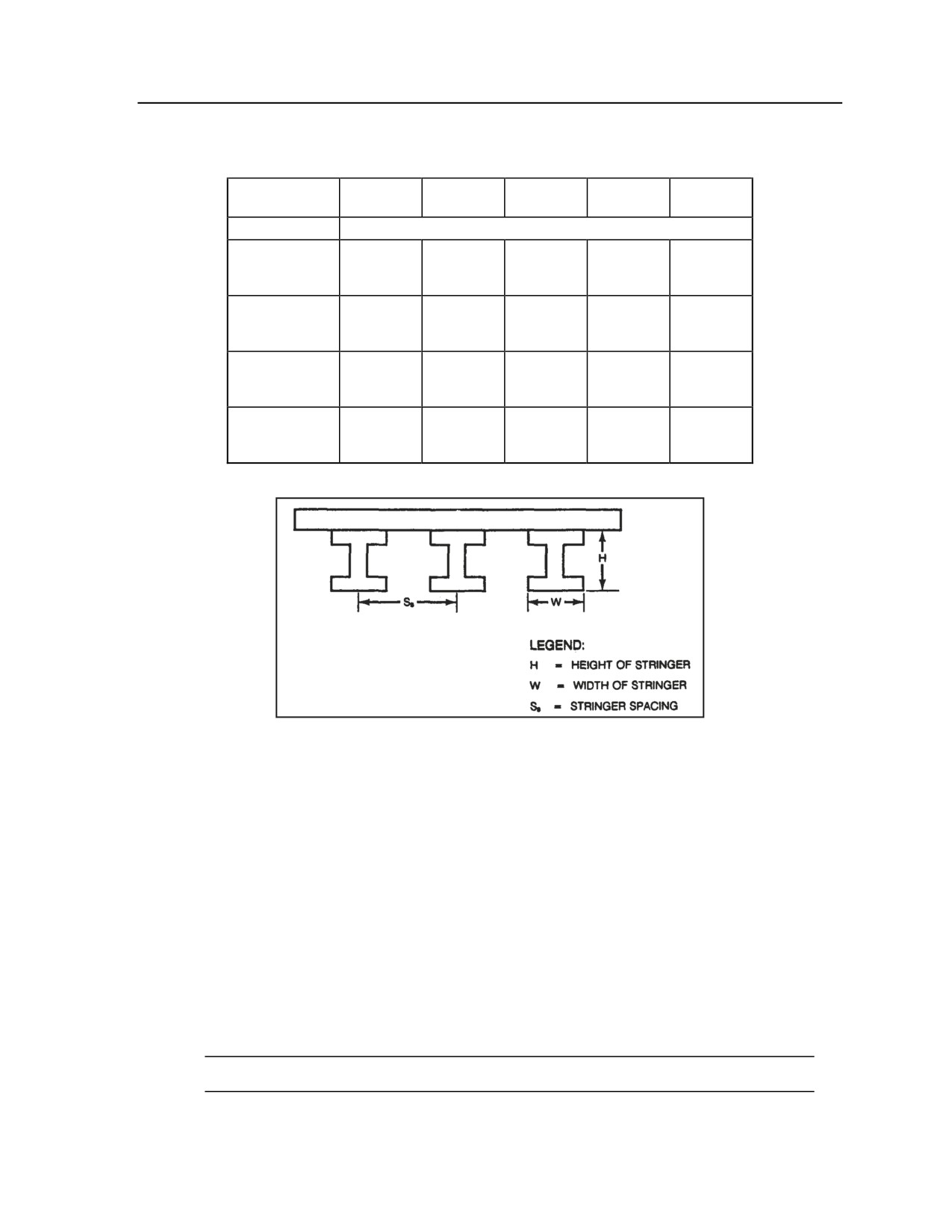
Figure G-33. Steel stringer MLC 30 bridge
with concrete deck
TIMBER/STEEL TRESTLE MLC 30 BRIDGE
G-82. Before crossing a timber/steel trestle MLC 30 bridge, use the following evaluation steps to determine
if it is safe to cross:
z
Step 1. Is the roadway width 4.5 meters (14.75 feet) or greater? Is there 4.3 meters (14 feet) of
overhead clearance? Is the deck at least 8 inches thick (for 6-foot stringer sections) or at least 6
inches thick (for stringer sections of 4 feet of less)? If the answer to all three questions is yes, go
to step 2 for a timber trestle bridge or step 3 for a steel trestle bridge. If the answer to any
question is no, do not cross.
z
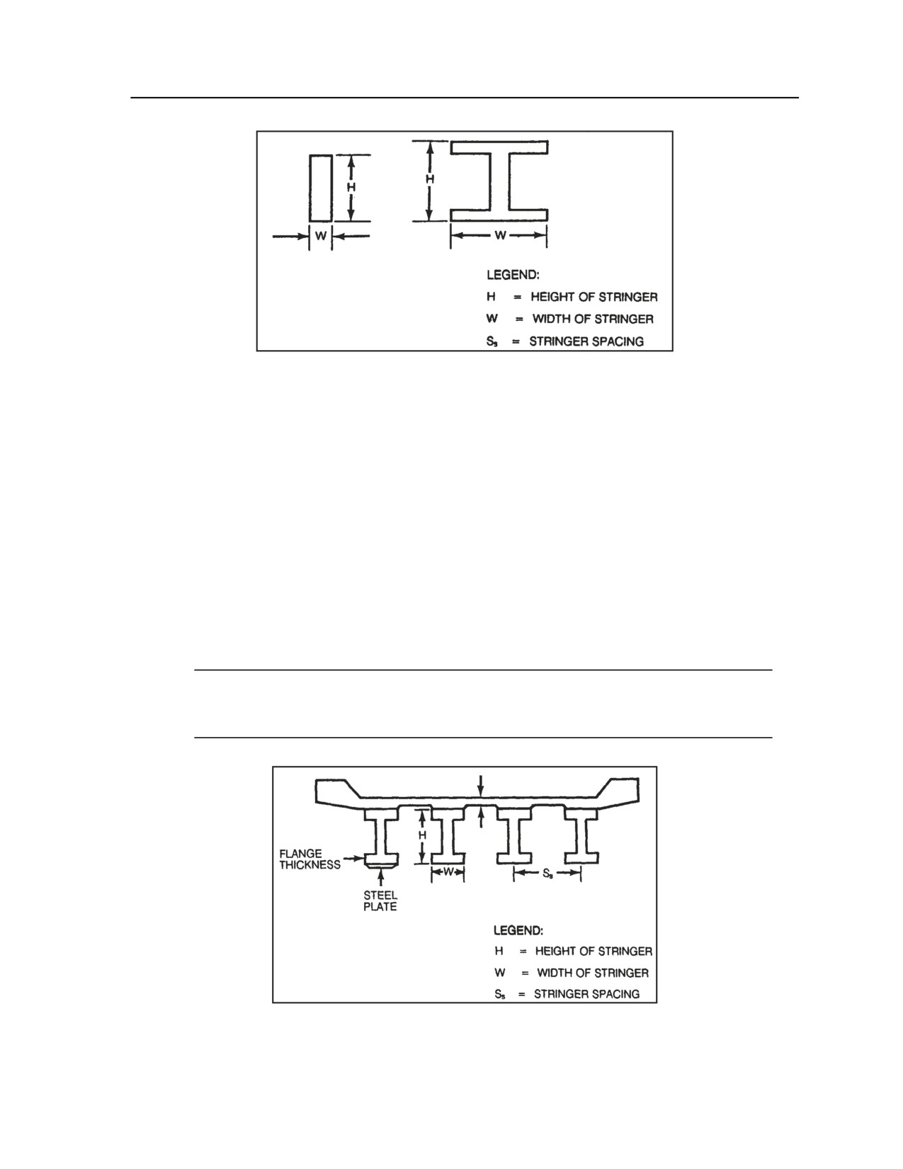
Step 2. For a timber trestle bridge, measure the span length, stringer spacing, and stringer
height and width
(refer to Figure G-34). Using Table G-8, find the row and column
corresponding to the bridge’s span length and stringer spacing. Does the timber stringer meet the
minimum requirements for overall height and width? If the answer is yes, it is safe to cross MLC
30 traffic; if the answer is no, do not cross.
Note. If these measurements fall between the values given, use the next higher measurement.
G-38
FM 3-20.98
3 August 2009
Essential Field Data
Table G-8. Measurement correlations for
a timber trestle MLC 30 bridge
20-FOOT
15-FOOT
10-FOOT
SPAN
SPAN
SPAN
STRINGER HEIGHT x WIDTH
(inches)
6-FOOT
22 x 8
18 x 8
16 x 6
STRINGER
SECTION
4-FOOT
20 x 8
16 x 8
14 x 6
STRINGER
SECTION
2-FOOT
16 x 8
14 x 8
12 x 6
STRINGER
SECTION
z
Step 3. For a steel trestle bridge, measure the span length, stringer spacing, and stringer height
and width (refer to Figure G-34). Using Table G-9, find the row and column corresponding to
the bridge’s span length and stringer spacing. Does the steel stringer meet the minimum
requirements for overall height and width? If the answer is yes, it is safe to cross MLC 30
traffic; if the answer is no, do not cross.
Note. If these measurements fall between the values given, use the next higher measurement.
Table G-9. Measurement correlations for
a steel trestle MLC 30 bridge
50-FOOT
40-FOOT
30-FOOT
25-FOOT
20-FOOT
SPAN
SPAN
SPAN
SPAN
SPAN
STRINGER HEIGHT x WIDTH (inches)
6-FOOT
24
24
18-1/8
15
14-1/8
STRINGER
x 7-3/8
x 7
x 7-1/2
x 5-7/8
x 5-5/8
SECTION
4-FOOT
24
22
15
14-1/8
14
STRINGER
x 7
x 7
x 5-7/8
x 5-5/8
x 5-1/2
SECTION
2-FOOT
20
18
14
13
10
STRINGER
x 6-1/2
x 6
x 5-1/2
x 5
x 5
SECTION
3 August 2009
FM 3-20.98
G-39
Appendix G
Figure G-34. Timber/steel trestle MLC 30 bridge
COMPOSITE STEEL-CONCRETE STRINGER MLC 30 BRIDGE
G-83. Before crossing a composite steel-concrete stringer MLC 30 bridge, use the following evaluation
steps to determine if it is safe to cross:
z
Step 1. Is the roadway width 4.5 meters (14.75 feet) or greater? Is there 4.3 meters (14 feet) of
overhead clearance? Is the deck at least 5 inches thick? If the answer to all three questions is
yes, go to step 2; if the answer to any question is no, do not cross.
z
Step 2. Inspect the stringer to see if there is a plate on the bottom. There are three possible
configurations: no plate, a plate one-half or less the thickness of the flange, or a plate more than
one-half the thickness of the flange. Measure the span length, stringer spacing, and stringer
height and width (as illustrated in Figure G-35). Using one of the tables included here, find the
row and column corresponding to the bridge’s span length and stringer spacing. Does the
stringer meet the overall height and width requirements for its corresponding span length,
stringer spacing, and plate status? If the answer is yes, it is safe to cross MLC 30 traffic; if the
answer is no, do not cross.
Note. Use Table G-10 for no plate, Table G-11 for a plate one-half or less the thickness of the
flange, or Table G-12 for a plate more than one-half the thickness of the flange. If the span
length or stringer spacing falls between the values given, use the next higher measurement.
Figure G-35. Composite steel-concrete stringer MLC 30 bridge
G-40
FM 3-20.98
3 August 2009
Essential Field Data
Table G-10. Measurement correlations for a composite
steel-concrete stringer MLC 30 bridge (with no plate)
50-FOOT
40-FOOT
30-FOOT
25-FOOT
20-FOOT
SPAN
SPAN
SPAN
SPAN
SPAN
STRINGER HEIGHT x WIDTH (inches)
10-FOOT
33-1/8
27-1/8
23-7/8
18
18
STRINGER
x 11-1/2
x 10
x 9
x 7-1/2
x 7-1/2
SECTION
8-FOOT
30-1/8
26-7/8
21-1/4
18
18
STRINGER
x 10-1/2
x 10
x 8-1/4
x 7-1/2
x 7-1/2
SECTION
6-FOOT
30
24-1/8
18-1/4
18
18
STRINGER
x 10-1/2
x 9
x 7-1/2
x 7-1/2
x 7-1/2
SECTION
4-FOOT
26-3/4
21-1/4
18-1/8
18
18
STRINGER
x 10
x 8-1/4
x 7-1/2
x 7-1/2
x 7-1/2
SECTION
Table G-11. Measurement correlations for a composite
steel-concrete stringer MLC 30 bridge (with a plate
one-half or less the thickness of the flange)
50-FOOT
40-FOOT
30-FOOT
25-FOOT
20-FOOT
SPAN
SPAN
SPAN
SPAN
SPAN
STRINGER HEIGHT x WIDTH (inches)
10-FOOT
30-1/8
26-7/8
21-1/4
18
18
STRINGER
x 10-1/2
x 10
x 8-1/4
x 7-1/2
x 7-1/2
SECTION
8-FOOT
30
24-1/8
21-1/8
18
18
STRINGER
x 10-1/2
x G-1/8
x 8-1/4
x 7-1/2
x 7-1/2
SECTION
6-FOOT
27-1/8
24-1/8
21
18
18
STRINGER
x 10
x 9
x 8-1/4
x 7-1/2
x 7-1/2
SECTION
4-FOOT
26-3/4
21-1/8
18
18
18
STRINGER
x 10
x 8-1/4
x 7-1/2
x 7-1/2
x 7-1/2
SECTION
3 August 2009
FM 3-20.98
G-41
Appendix G
Table G-12. Measurement correlations for a composite
steel-concrete stringer MLC 30 bridge (with a plate
more than one-half the thickness of the flange)
50-FOOT
40-FOOT
30-FOOT
25-FOOT
20-FOOT
SPAN
SPAN
SPAN
SPAN
SPAN
STRINGER HEIGHT x WIDTH (inches)
10-FOOT
30
24-1/4
21-1/4
18
18
STRINGER
x 10-1/2
x G-1/8
x 8-1/4
x 7-1/2
x 7-1/2
SECTION
8-FOOT
2G-7/8
24-1/4
21-1/8
18
18
STRINGER
x 10-1/2
x G-1/8
x 8-1/4
x 7-1/2
x 7-1/2
SECTION
6-FOOT
27-1/8
23-7/8
18-1/4
18
18
STRINGER
x 10
x 9
x 7-1/2
x 7-1/2
x 7-1/2
SECTION
4-FOOT
24-1/8
21-1/8
18
18
18
STRINGER
x 9
x 8-1/4
x 7-1/2
x 7-1/2
x 7-1/2
SECTION
CONCRETE SLAB MLC 70 BRIDGE
G-84. Before crossing a concrete slab MLC 70 bridge, use the following evaluation steps to determine if it
is safe to cross:
z
Step 1. Is the roadway width 4.5 meters (14.75 feet) or greater? Is there 4.3 meters (14 feet) of
overhead clearance? If the answer to both questions is yes, go to step 2; if the answer to either
question is no, do not cross.
z
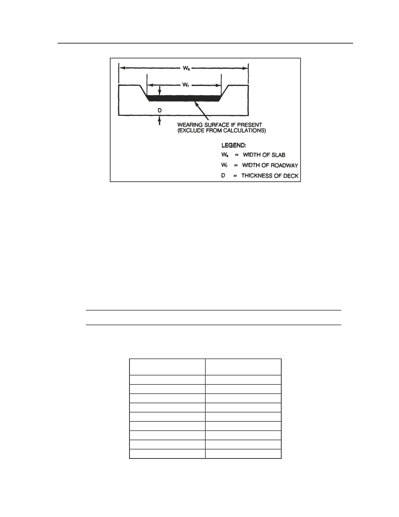
Step 2. Measure the span length and deck thickness (refer to Figure G-36). Compare the span
length and deck thickness to minimum standards using Table G-13. Does the slab meet
minimum deck thickness for the corresponding span? If the answer is yes, it safe to cross MLC
70 traffic; if the answer is no, go to step 3.
Table G-13. Measurement correlations for
a concrete slab MLC 70 bridge
SPAN LENGTH
MINIMUM DECK
THICKNESS
30 feet
22 inches
20 feet
17 inches
10 feet
12 inches
z
Step 3. Take into account the following special condition: For each foot under the closest
higher span length shown the deck thickness can decrease by no more than ½ inch. Does the
slab meet minimum deck thickness required according to this special condition? If the answer is
yes, it is safe to cross MLC 70 traffic; if the answer is no, do not cross.
G-42
FM 3-20.98
3 August 2009
Essential Field Data
Figure G-36. Concrete slab MLC 70 bridge
CONCRETE T-BEAM MLC 70 BRIDGE
G-85. Before crossing a concrete T-beam MLC 70 bridge, use the following evaluation steps to determine
if it is safe to cross:
z
Step 1. Is the roadway width 4.5 meters (14.75 feet) or greater? Is there 4.3 meters (14 feet) of
overhead clearance? Is the deck at least 6 inches thick? If the answer to all three questions is
yes, go to step 2; if the answer to any question is no, do not cross.
z
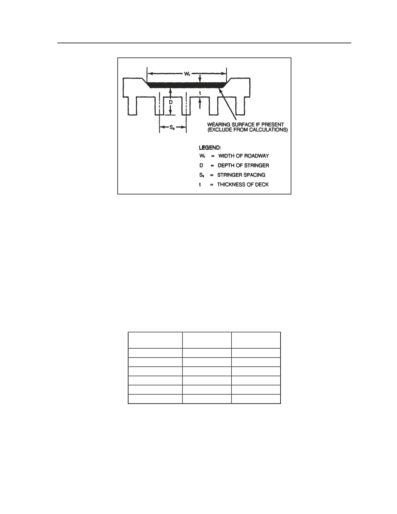
Step 2. Measure the span length, stringer spacing, and depth of the stringer (as illustrated in
Figure G-37). Is the stringer spacing no less than 6 feet and no more than 8 feet? If the answer is
yes, go to step 3; if the answer is no, do not cross.
z
Step 3. Does the stringer depth meet the minimum dimension for the corresponding span length
in Table G-14? If the answer is yes, it is safe to cross MLC 70 traffic; if the answer is no, do not
cross.
Note. If the span length falls between designated lengths, use the next higher value.
Table G-14. Measurement correlations for
a concrete T-beam MLC 70 bridge
SPAN LENGTH
MINIMUM STRINGER
DEPTH
20 feet
20 inches
30 feet
26 inches
40 feet
32 inches
50 feet
39 inches
60 feet
45 inches
70 feet
50 inches
80 feet
55 inches
90 feet
61 inches
100 feet
66 inches
3 August 2009
FM 3-20.98
G-43
Appendix G
Figure G-37. Concrete T-beam MLC 70 bridge
MASONRY ARCH MLC 70 BRIDGE
G-86. Before crossing a masonry arch MLC 70 bridge, use the following evaluation steps to determine if it
is safe to cross:
z
Step 1. Is the roadway width 4.5 meters (14.75 feet) or greater? Is there 4.3 meters (14 feet) of
overhead clearance? If the answer to both questions is yes, go to step 2; if the answer to either
question is no, do not cross.
z
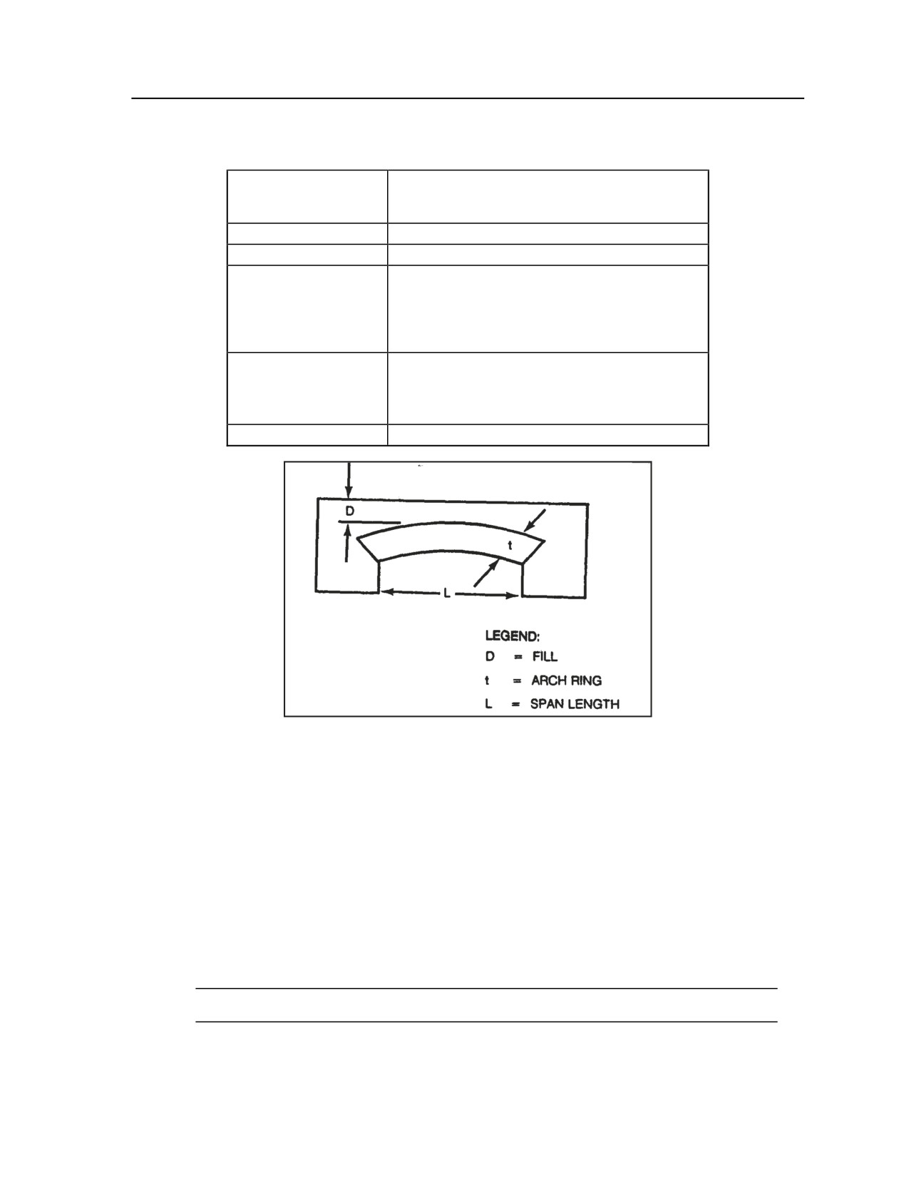
Step 2. Measure the span length, arch ring, and fill (as shown in Figure G-38). Compare these
measurements to minimum standards using Table G-15. Do the arch ring and fill meet minimum
required dimensions for the designated span? If the answer is yes, it is safe to cross MLC 70
traffic; if the answer is no, go to step 3.
Table G-15. Measurement correlations for
a masonry arch MLC 70 bridge
SPAN LENGTH
MINIMUM
MINIMUM FILL
ARCH RING
10 feet
9 inches
6 inches
15 feet
9 inches
12 inches
20 feet
9 inches
24 inches
30 feet
13.5 inches
24 inches
40 feet
18 inches
24 inches
50 feet
22.5 inches
24 inches
z
Step 3. Take into account the following special condition: Fill can be reduced if the thickness
of the arch ring exceeds the specifications above. Compare these measurements using Table G-
16. Does the bridge span meet the minimum fill requirements for the corresponding arch ring
thickness according to this special condition? If the answer is yes, it is safe to cross MLC 70
traffic; if the answer is no, do not cross.
G-44
FM 3-20.98
3 August 2009
Essential Field Data
Table G-16. Special conditions for minimum fill
on a masonry arch MLC 70 bridge
SPAN LENGTH
FOR EACH 1-INCH INCREASE ABOVE THE
MINIMUM ARCH RING, FILL CAN DECREASE
BY:
10 feet
Not applicable; fill must be no less than 6 inches
15 feet
1-1/4 inches
20 feet
If arch rings are 9 to 13.5 inches thick, fill can
decrease by 2-1/2 inches (total)
If arch rings are more than 13.5 inches thick, fill
can decrease by 1-1/4 inches per inch above
minimum
30 feet
If arch rings are 13.5 to 18 inches thick, fill can
decrease by 2-1/2 inches (total)
If arch rings are more than 18 inches thick, fill can
decrease by 1-1/4 inches per inch above minimum
40 feet and 50 feet
1-1/4 inches
Figure G-38. Masonry arch MLC 70 bridge
STEEL STRINGER MLC 70 BRIDGE WITH CONCRETE DECK
G-87. Before crossing a steel stringer MLC 70 bridge with a concrete deck, use the following evaluation
steps to determine if it is safe to cross:
z
Step 1. Is the roadway width 4.5 meters (14.75 feet) or greater? Is there 4.3 meters (14 feet) of
overhead clearance? Is the deck at least 5 inches and no more than 8 inches thick? If the answer
to all three questions is yes, go to step 2; if the answer to any question is no, do not cross.
z
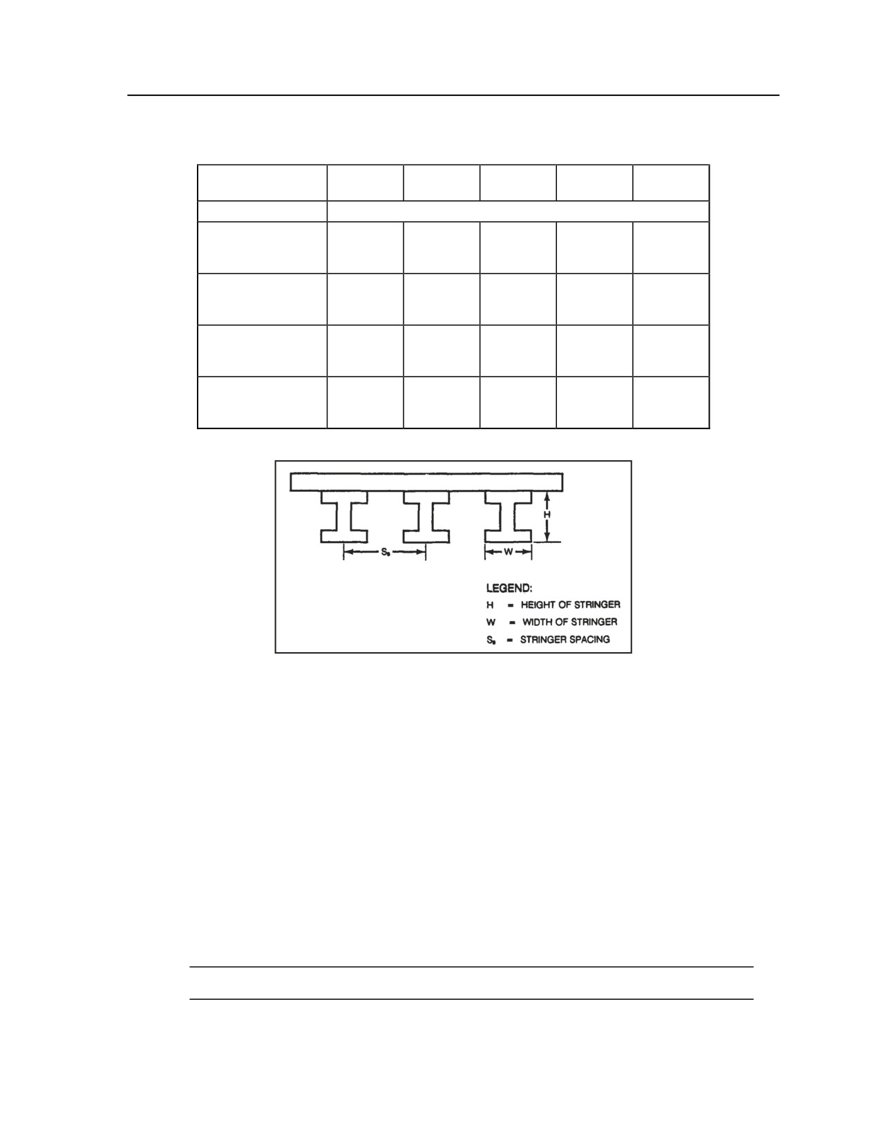
Step 2. Measure the span length, stringer spacing, and stringer height and width (as illustrated
in Figure G-39). Using Table G-17, find the row and column corresponding to the span length
and stringer spacing of the bridge. Does the stringer meet the minimum requirements for overall
height and width? If the answer is yes, it is safe to cross MLC 70 traffic; if the answer is no, do
not cross.
Note. If these measurements fall between the values given, use the next higher measurement.
3 August 2009
FM 3-20.98
G-45
Appendix G
Table G-17. Measurement correlations for a steel stringer
MLC 70 bridge with concrete deck
50-FOOT
40-FOOT
30-FOOT
25-FOOT
20-FOOT
SPAN
SPAN
SPAN
SPAN
SPAN
STRINGER HEIGHT x WIDTH (inches)
8-FOOT
2G-1/2
23-5/8
21-5/8
16-3/4
14-1/4
STRINGER
x 11-3/4
x 11-3/4
x 11-3/4
x 11-3/4
x 11-3/4
SECTION
6-FOOT
27-1/2
21-5/8
21-5/8
16-3/4
13-3/8
STRINGER
x 11-3/4
x 11-3/4
x 11-3/4
x 11-3/4
x 11-3/4
SECTION
4-FOOT
23-5/8
1G-5/8
16-3/4
14-1/4
13-3/8
STRINGER
x 11-3/4
x 11-3/4
x 11-3/4
x 11-3/4
x 11-3/4
SECTION
2-FOOT
17-3/4
16-3/4
13-3/8
13-3/8
11
STRINGER
x 11-3/4
x 11-3/4
x 11-3/4
x 11-3/4
x 11
SECTION
Figure G-39. Steel stringer MLC 70 bridge
with concrete deck
TIMBER/STEEL TRESTLE MLC 70 BRIDGE
G-88. Before crossing a timber/steel trestle MLC 70 bridge, use the following evaluation steps to determine
if it is safe to cross:
z
Step 1. Is the roadway width 4.5 meters (14.75 feet) or greater? Is there 4.3 meters (14 feet) of
overhead clearance? Is the deck at least 8 inches thick (for 6-foot stringer sections) or at least 6
inches thick (for stringer sections of 4 feet of less)? If the answer to all three questions is yes, go
to step 2 for a timber trestle bridge or step 3 for a steel trestle bridge. If the answer to any
question is no, do not cross.
z
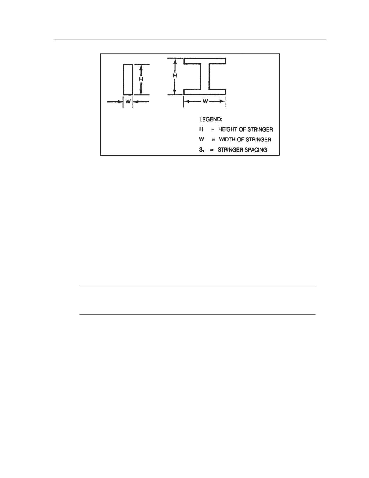
Step 2. For a timber trestle bridge, measure the span length, stringer spacing, and stringer
height and width (as illustrated in Figure G-40). Using Table G-18, find the row and column
corresponding to the bridge’s span length and stringer spacing. Does the timber stringer meet the
minimum requirements for overall height and width? If the answer is yes, it is safe to cross MLC
70 traffic; if the answer is no, do not cross.
Note. If these measurements fall between the values given, use the next higher measurement.
G-46
FM 3-20.98
3 August 2009
Essential Field Data
Table G-18. Measurement correlations for
a timber trestle MLC 70 bridge
20-FOOT
15-FOOT
10-FOOT
SPAN
SPAN
SPAN
STRINGER HEIGHT x WIDTH (inches)
6-FOOT
24 x 12
24 x 10
18 x 8
STRINGER
SECTION
4-FOOT
22 x 12
22 x 8
16 x 8
STRINGER
SECTION
2-FOOT
22 x 12
20 x 8
14 x 8
STRINGER
SECTION
z
Step 3. For a steel trestle bridge, measure the span length, stringer spacing, and stringer height
and width (refer to Figure G-40). Using Table G-19, find the row and column corresponding to
the bridge’s span length and stringer spacing. Does the steel stringer meet the minimum
requirements for overall height and width? If the answer is yes, it is safe to cross MLC 70
traffic; if the answer is no, do not cross.
Note. If these measurements fall between the values given, use the next higher measurement.
Table G-19. Measurement correlations for
a steel trestle MLC 70 bridge
50-FOOT
40-FOOT
30-FOOT
25-FOOT
20-FOOT
SPAN
SPAN
SPAN
SPAN
SPAN
STRINGER HEIGHT x WIDTH (inches)
6-FOOT
27-1/2
23-5/8
1G-5/8
16-3/4
13-3/8
STRINGER
x 11-3/4
x 11-3/4
x 11-3/4
x 11-3/4
x 11-3/4
SECTION
4-FOOT
23-5/8
1G-5/8
16-3/4
15-3/4
13-3/8
STRINGER
x 11-3/4
x 11-3/4
x 11-3/4
x 11-3/4
x 11-3/4
SECTION
2-FOOT
1G-5/8
16-3/4
13-3/8
11
11
STRINGER
x 11-3/4
x 11-3/4
x 11-3/4
x 11
x 11
SECTION
3 August 2009
FM 3-20.98
G-47
Appendix G
Figure G-40. Timber/steel trestle MLC 70 bridge
COMPOSITE STEEL-CONCRETE STRINGER MLC 70 BRIDGE
G-89. Before crossing a composite steel-concrete stringer MLC 70 bridge, use the following evaluation
steps to determine if it is safe to cross:
z
Step 1. Is the roadway width 4.5 meters (14.75 feet) or greater? Is there 4.3 meters (14 feet) of
overhead clearance? Is the deck at least 5 inches thick? If the answer to all three questions is
yes, go to step 2; if the answer to any question is no, do not cross.
z
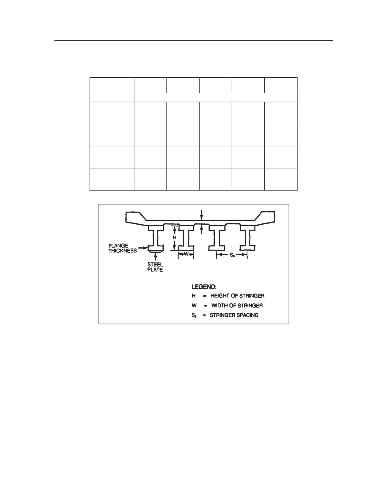
Step 2. Inspect the stringer to see if there is a plate on the bottom. There are three possible
configurations: no plate, a plate one-half or less the thickness of the flange, or a plate more than
one-half the thickness of the flange. Measure the span length, stringer spacing, and stringer
height and width (as shown in Figure G-41). Using one of the tables included here, find the row
and column corresponding to the bridge’s span length and stringer spacing. Does the stringer
meet the overall height and width requirements for its corresponding span length, stringer
spacing, and plate status? If the answer is yes, it is safe to cross MLC 70 traffic; if the answer is
no, do not cross.
Note. Use Table G-20 for no plate, Table G-21 for a plate one-half or less the thickness of the
flange, or Table G-22 for a plate more than one-half the thickness of the flange. If the span
length or stringer spacing falls between the values given, use the next higher measurement.
G-48
FM 3-20.98
3 August 2009
Essential Field Data
Table G-20. Measurement correlations for a composite
steel-concrete stringer MLC 70 bridge (with no plate)
50-FOOT
40-FOOT
30-FOOT
25-FOOT
20-FOOT
SPAN
SPAN
SPAN
SPAN
SPAN
STRINGER HEIGHT x WIDTH (inches)
10-FOOT
33-7/8
36
30-1/8
24-1/8
18
STRINGER
x 15-3/4
x 12
x 10-1/2
x 9
x 7-1/2
SECTION
8-FOOT
36-1/2
35-7/8
30
23-7/8
18
STRINGER
x 12-1/8
x 12
x 10-1/2
x 9
x 7-1/2
SECTION
6-FOOT
36-1/8
33-1/4
2G-7/8
21-1/4
18
STRINGER
x 12
x 11-1/2
x 10-1/2
x 8-1/4
x 7-1/2
SECTION
4-FOOT
35-7/8
30
26-3/4
18-1/4
18
STRINGER
x 12
x 10-1/2
x 10
x 7-1/2
x 7-1/2
SECTION
Table G-21. Measurement correlations for a composite
steel-concrete stringer MLC 70 bridge (with a plate
one-half or less the thickness of the flange)
50-FOOT
40-FOOT
30-FOOT
25-FOOT
20-FOOT
SPAN
SPAN
SPAN
SPAN
SPAN
STRINGER HEIGHT x WIDTH (inches)
10-FOOT
36-3/4
35-7/8
30
24-1/8
18
STRINGER
x 16-5/8
x 12
x 10-1/2
x 9
x 7-1/2
SECTION
8-FOOT
36-3/8
35-7/8
2G-7/8
23-7/8
18
STRINGER
x 12-1/8
x 12
x 10-1/2
x 9
x 7-1/2
SECTION
6-FOOT
36
33-1/8
27-1/8
21-1/8
18
STRINGER
x 12
x 11-1/2
x 10
x 8-1/2
x 7-1/2
SECTION
4-FOOT
33-1/4
30
24-1/4
18-1/4
18
STRINGER
x 11-1/2
x 10-1/2
x 9
x 7-1/2
x 7-1/2
SECTION
3 August 2009
FM 3-20.98
G-49
Appendix G
Table G-22. Measurement correlations for a composite
steel-concrete stringer MLC 70 bridge (with a plate
more than one-half the thickness of the flange)
50-FOOT
40-FOOT
30-FOOT
25-FOOT
20-FOOT
SPAN
SPAN
SPAN
SPAN
SPAN
STRINGER HEIGHT x WIDTH (inches)
10-FOOT
36-1/2
35-7/8
30
23-7/8
18
STRINGER
x 12-1/8
x 12
x 10-1/2
x 9
x 7-1/2
SECTION
8-FOOT
36-3/8
33-1/4
2G-7/8
23-7/8
18
STRINGER
x 12-1/8
x 11-1/2
x 10-1/2
x 9
x 7-1/2
SECTION
6-FOOT
36
33-1/8
27-1/8
21-1/8
18
STRINGER
x 12
x 11-1/2
x 10
x 8-1/4
x 7-1/2
SECTION
4-FOOT
33-1/4
30
26-7/8
18-1/4
18
STRINGER
x 11-1/2
x 10-1/2
x 10
x 7-1/2
x 7-1/2
SECTION
Figure G-41. Composite steel-concrete stringer MLC 70 bridge
AVLB CROSSING RECONNAISSANCE
G-90. Generally, the best site to deploy an AVLB is across a span where a bridge has been destroyed or
across an existing bridge that will not hold the unit’s vehicles. In both cases, abutments on both sides
should be intact, in good shape, and less than 80 feet apart. Crossing at areas without bridge abutments
requires a detailed evaluation of both sides to ensure the ground is firm enough to hold both the bridge and
the heaviest vehicle in the unit. Once a bridge has been buried in the mud at both ends, it is difficult to
retrieve. Refer to Table G-23 for a summary of AVLB characteristics.
G-50
FM 3-20.98
3 August 2009
Essential Field Data
Table G-23. AVLB characteristics
ALLOCATION
Engineer battalion of a heavy division:
12 launchers
12 bridges
Engineer company of an armor/infantry (M) separate brigade:
4 launchers
4 bridges
TRANSPORTATION
Bridge carried on launcher (modified M48 or M60A1 chassis)
Bridge weights 15 tons
20-ton crane transfers bridge to launcher in 20 to 30 minutes
CAPABILITIES
MLC 60 vehicle
One vehicle at a time can cross the AVLB
AVLB is 19.2 meters (63 feet) long. It spans these gaps:
18.3 meters (60 feet) using prepared abutments
17 meters (57 feet) using unprepared abutments
ASSEMBLY/
Launched in 2 to 5 minutes by buttoned-up 2-man crew
PROPULSION
Retrieved from either end; one Soldier exposed; guide and
connect
Allow 0.9 meter (3 feet) bearing for unprepared abutment, 0.5
meter (1.5 feet) for prepared abutment
REMARKS/
M48A2 requires gas; M60 and M48A5 are diesel
LIMITATIONS
Scissors launch requires 10 meters (32.8 feet) overhead
clearance
Maximum launch slope:
Uphill - 2.7 meters (9 feet)
Downhill - 2.7 meters (9 feet)
Sideslope - 0.3 meters (1 feet)
AVLB fords water 1.2 meters (4 feet) deep
BRIDGE CONDITION
G-91. It is essential to note the bridge’s general condition, paying particular attention to evidence of
damage from natural causes
(such as rot, rust, and deterioration) or combat action. Classification
procedures presume that a bridge is in good condition. If the bridge is in poor condition, the class
determined through mathematical computations must be reduced according to the classifier’s judgment.
WIDTH AND HEIGHT RESTRICTIONS
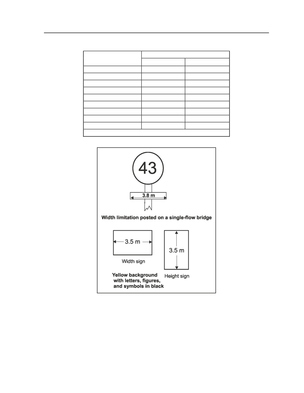
G-92. Table G-24 summarizes width restrictions for bridges. If a one-lane bridge does not meet width
requirements, post a rectangular warning sign under the classification sign showing the actual clear width
(see Figure G-42). If it is a route restriction, annotate it in the route classification formula. For a two-lane
bridge, downgrade the two-way classification to the highest class for which it does qualify (one-way
classification is not affected). Post a limited-clearance sign if the overhead clearance is less than 4.3
meters. These signs must be a minimum of 40 centimeters in height or width, with a yellow background
and the appropriate description in black letters. Separate rectangular signs are used if necessary to denote
width limitations, height limitations, or other technical information.
Note. The same signs are used for tunnels, if applicable.
3 August 2009
FM 3-20.98
G-51
Appendix G
Table G-24. Minimum roadway widths
BRIDGE CLASSIFICATION
ROADWAY WIDTH
(meters)
One-way
Two-way
2.75 to 3.34
12
0
3.35 to 3.99
30
0
4 to 4.49
60
0
4.5 to 4.99
100
0
5 to 5.4
150
0
5.5 to 7.2
150
30
7.3 to 8.1
150
60
8.2 to 9.7
150
100
Over 9.8
150
150
Note. Minimum overhead clearance for all classes is 4.3 meters.
Figure G-42. Width and height signs
BRIDGE TRAFFIC CONTROL PROCEDURES
G-93. Posting standard bridge signs and other signs needed for proper and efficient traffic control across a
bridge is the engineer’s responsibility. Additional signs are used when vehicles require special controls
while crossing. When necessary, holding areas, turnouts for parking and unloading vehicles, and
checkpoints are installed near bridges to provide the necessary control during crossings.
G-52
FM 3-20.98
3 August 2009
Essential Field Data
FULL NATO BRIDGE SYMBOL
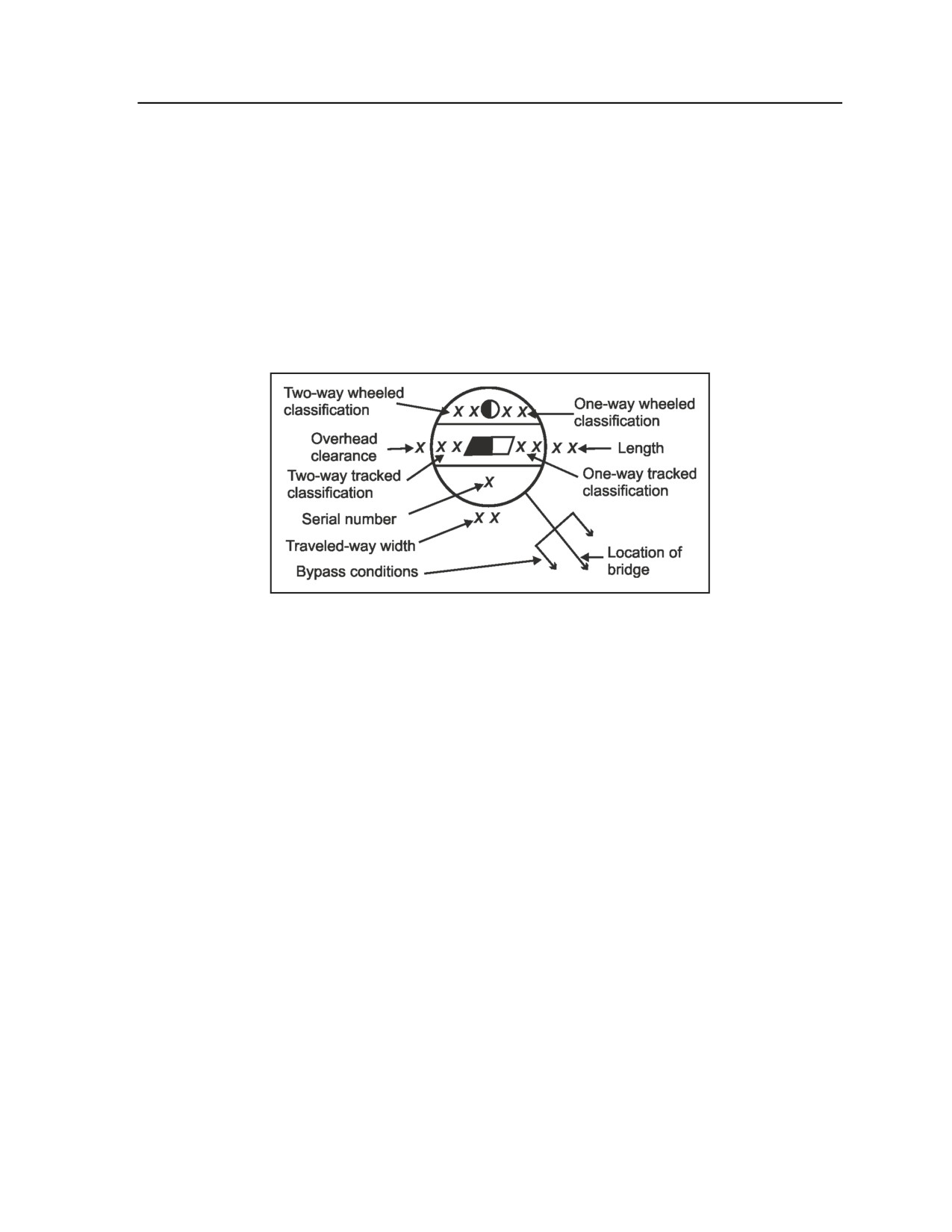
G-94. Bridge information is recorded on a map or overlay using the full NATO bridge symbol (refer to
Figure G-43). It is different from an on-site bridge classification sign; do not confuse the two. The
information necessary for the full NATO bridge symbol includes the following:
z
Bridge’s serial number.
z
Geographic location.
z
Bridge’s MLC.
z
Overall length.
z
Traveled-way width.
z
Overhead clearance.
z
Available bypasses.
Figure G-43. Full NATO bridge symbol
G-95. A bridge serial number is assigned for future reference and is recorded in the symbol’s lower portion
(assign a number according to unit SOP). For proper identification, do not duplicate serial numbers within
any single map sheet, overlay, or document. The unit S2 can obtain special maps containing bridge
information for developed areas of the world.
G-96. An arrow extending from the symbol to the exact map location shows the bridge’s geographic
location. The bridge’s MLC number is shown in the symbol’s top portion. This number indicates the
bridge’s carrying capacity; classifications for both single- and double-flow traffic are included. In those
instances where dual classifications for wheeled and tracked vehicles exist, both classifications are shown.
G-97. The bridge’s overall length is the distance between abutments, measured along the bridge’s
centerline. This figure is placed to the right of the circle and is expressed in meters.
G-98. The minimum lane width is the clear distance between curbs. Place this figure below the symbol and
express it in meters. Bridges may be obstructions to traffic flow when the traveled-way width on the bridge
is less than the minimum standard prescribed for the overall route. Refer to the minimum roadway widths
listed earlier in Table G-24.
G-99. The overhead clearance is the minimum distance between the bridge’s surface and any obstruction
above it. This figure is shown (in meters) to the left of the symbol. Underline any overhead clearance less
than the minimum required by the bridge classification number (refer to Table G-25). Unlimited overhead
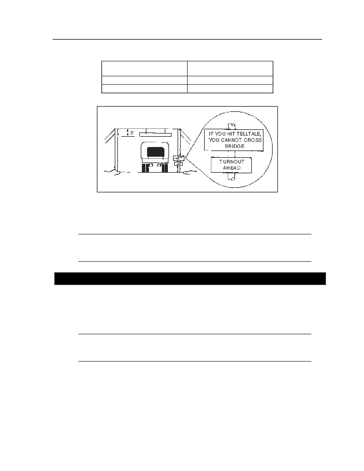
clearance is indicated by the infinity symbol (). Often, a telltale (see Figure G-44) or other warning
device can be posted before the bridge to indicate overhead clearance limitations. Report any overhead
clearance less than 4.3 meters as an obstruction in the route classification formula. A question mark is used
to indicate information that is unknown or undetermined and is included as part of the bridge
reconnaissance symbol.
3 August 2009
FM 3-20.98
G-53
Appendix G
Table G-25. Minimum overhead clearances
MINIMUM OVERHEAD
BRIDGE CLASSIFICATION
CLEARANCE
Up to MLC 70
4.5 meters
Above MLC 70
4.5 meters
Figure G-44. Use of telltale for bridge restrictions
G-100. Bypasses around the bridge site are indicated using arrows similar to (and branching away from)
the arrow connecting the bridge symbol to its location on the map. Bypass arrows should show the
approximate route of the bypass. Refer to the discussion of bypasses in the following section.
Note. Railway bridges that could be used by road vehicles in an emergency should be classified
and identified on the map or overlay. The symbol for a railway bridge should indicate whether it
is “use easy” or “use difficult.”
SECTION X - BYPASSES
G-101. Bypasses are detours along a route allowing traffic to avoid an obstruction. Bypasses limited to
specific vehicle types, such as those capable of swimming or deep-water fording, are noted in the
reconnaissance report. Each bypass is represented symbolically as an arrow. The bypass arrow extends
either from the tunnel, ford, bridge, or overpass symbol itself or from the arrow that connects the symbol to
the map location of the tunnel, ford, bridge, or overpass. The arrow should indicate the approximate route
of the bypass.
Note. Platoons may employ UAS overflights to preview the terrain for advanced knowledge of
an area prior to reaching the location. HUMINT may provide advance information on
established bypasses known by the local population.
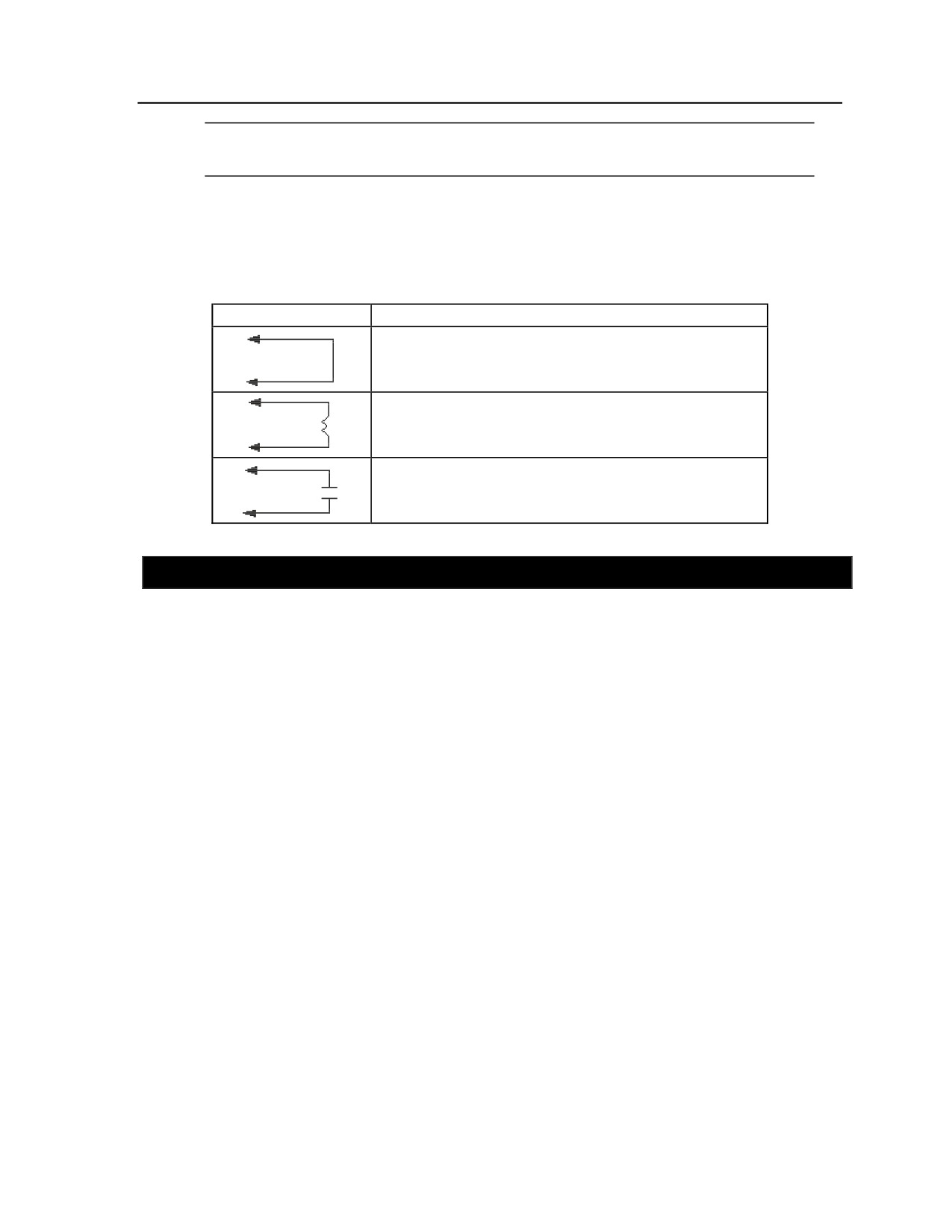
G-102. Bypasses are classified as easy, difficult, or impossible. Table G-26 illustrates the map symbols
used to indicate each bypass classification. Considerations for the bypass categories include the following:
z
A bypass is considered easy when a 5-ton vehicle can cross the obstacle within the immediate
vicinity without work to improve the bypass.
z
A difficult bypass also allows vehicles to cross the obstacle within the immediate vicinity;
however, some work will be necessary to prepare the bypass.
G-54
FM 3-20.98
3 August 2009
Essential Field Data
Note. An estimation of the time, manpower, and equipment necessary to prepare the bypass
must be included in the reconnaissance report.)
z
The bypass is considered impossible when it would entail repairing an existing route feature
(such as a bridge or tunnel) to cross the obstacle, building a new feature, or providing a detour
to cross or move around the obstacle outside the immediate vicinity of the original route.
Table G-26. Bypass symbols
SYMBOL
CLASSIFICATION AND DESCRIPTION
BYPASS EASY. Use when the obstacle can be
crossed in the immediate vicinity by a U.S. 5-ton truck
without work to improve the bypass.
BYPASS DIFFICULT. Use when the obstacle can
be crossed in the immediate vicinity, but some work
is necessary to improve the bypass.
BYPASS IMPOSSIBLE. Use when the obstacle can
be crossed only by repairing or constructing a route
feature or by detouring around the obstacle.
SECTION XI - MEASUREMENT CONVERSIONS
G-103. This section includes tables covering the basic computations for converting English measurements
to their metric equivalents. The following conversions are included:
z
Table G-27 lists conversions for common distance measurements (inches to centimeters; feet to
meters; yards to meters; miles to kilometers).
z
Table G-28 shows conversions of miles per hour to kilometers per hour.
3 August 2009
FM 3-20.98
G-55

Appendix G
Table G-27. English to metric distance measurement conversions
INCHES to CENTIMETERS
FEET to METERS
1 inch = 2.54 centimeters
1 foot = 0.30 meters
2 inches = 5.08 centimeters
2 feet = 0.61 meters
3 inches = 7.62 centimeters
3 feet = 0.91 meters
4 inches = 10.16 centimeters
4 feet = 1.22 meters
5 inches = 12.70 centimeters
5 feet = 1.52 meters
6 inches = 15.24 centimeters
6 feet = 1.83 meters
7 inches = 17.78 centimeters
7 feet = 2.13 meters
8 inches = 20.32 centimeters
8 feet = 2.44 meters
9 inches = 22.86 centimeters
9 feet = 2.74 meters
10 inches = 25.40 centimeter
10 feet = 3.05 meters
20 inches = 50.80 centimeters
20 feet = 6.10 meters
30 inches = 76.20 centimeters
30 feet = 9.14 meters
40 inches = 101.60 centimeters
40 feet = 12.19 meters
50 inches = 127.00 centimeters
50 feet = 15.24 meters
60 inches = 152.40 centimeters
60 feet = 18.29 meters
70 inches = 177.80 centimeters
70 feet = 21.34 meters
80 inches = 203.20 centimeters
80 feet = 24.38 meters
90 inches = 228.60 centimeters
90 feet = 27.43 meters
100 inches = 254.00 centimeters
100 feet = 30.48 meters
YARDS to METERS
MILES to KILOMETERS
1 yard = 0.91 meters
1 mile = 1.61 km
2 yards = 1.83 meters
2 miles = 3.22 km
3 yards = 2.74 meters
3 miles = 4.83 km
4 yards = 3.66 meters
4 miles = 6.44 km
5 yards = 4.57 meters
5 miles = 8.05 km
6 yards = 5.49 meters
6 miles = 9.66 km
7 yards = 6.40 meters
7 miles = 11.27 km
8 yards = 7.32 meters
8 miles = 12.87 km
9 yards = 8.23 meters
9 miles = 14.48 km
10 yards = 9.14 meters
10 miles = 16.09 km
20 yards = 18.29 meters
20 miles = 32.19 km
30 yards = 27.43 meters
30 miles = 48.28 km
40 yards = 36.58 meters
40 miles = 64.37 km
50 yards = 45.72 meters
50 miles = 80.47 km
60 yards = 54.86 meters
60 miles = 96.56 km
70 yards = 64.00 meters
70 miles = 112.65 km
80 yards = 73.15 meters
80 miles = 128.75 km
90 yards = 82.30 meters
90 miles = 144.84 km
100 yards = 91.44 meters
100 miles = 62.14 km
G-56
FM 3-20.98
3 August 2009
Essential Field Data
Table G-28. Miles per hour to
kilometers per hour (kmph) conversions
MILES PER HOUR
KILOMETERS PER HOUR
1 mph
1.609 kmph
2 mph
3.22 kmph
3 mph
4.83 kmph
4 mph
6.44 kmph
5 mph
8.05 kmph
6 mph
9.66 kmph
7 mph
11.27 kmph
8 mph
12.87 kmph
9 mph
14.48 kmph
10 mph
16.09 kmph
15 mph
24.14 kmph
20 mph
32.19 kmph
25 mph
40.23 kmph
30 mph
48.28 kmph
35 mph
56.33 kmph
40 mph
64.37 kmph
45 mph
72.42 kmph
50 mph
80.47 kmph
55 mph
88.51 kmph
60 mph
96.56 kmph
65 mph
104.61 kmph
70 mph
112.65 kmph
75 mph
120.70 kmph
100 mph
160.94 kmph
3 August 2009
FM 3-20.98
G-57
This page intentionally left blank.
Appendix H
Demolitions and Obstacles
This appendix provides information on demolitions commonly used in platoon
operations and on obstacles that scouts may have to breach or construct in their AO.
SECTION I - DEMOLITIONS
H-1. A reconnaissance or scout section’s basic load of demolitions will provide enough explosives and
mines to breach or construct an obstacle during a mission. This discussion outlines basic guidelines for the
employment of demolitions in military operations. Table H-1 summarizes the characteristics and uses of
military explosives.
WARNING
This discussion and accompanying illustrations may not provide
enough information to allow safe employment of explosives;
therefore, scouts must be thoroughly familiar with fuzes, charge
settings, and firing demolitions before using this information. For
more information, refer to FM 3-34.214 and DA Pam 350-38.
3 August 2009
FM 3-20.98
H-1
Appendix H
Table H-1. Characteristics of military explosives
Detonation
Relative
Size, Weight, and
Explosive
Use
Velocity
Effectiveness
Packaging
(fps)/(mps)
Factor
1 lb: 48/box
TNT
Breaching/demolition
22,600/6,900
1.00
1/2 lb: 96/box
1/4 lb: 192/box
8 X 2.5 lb/sack,
Tetrytol 75/25
Breaching/demolition
23,000/7,000
1.20
2 sacks/box
30 X 1.25 lb block/box
C4 (M112)
Cutting and breaching
26,400/8,040
1.34
(1 block=2”x1”x10”
=20 cu in)
4 X 1/2 lb sheets/pack
Sheet
w/20 packs/box
Explosive
Cutting
24,000/7,300
1.14
(one sheet is
(M186)
3 x ¼ x 12 in)
M1 Dynamite
Demolition
20,000/6,100
0.92
100 X1/2 lb sticks/box
Detonating
20,000 to 24,000/
3 X 1,000 ft rolls or
Priming demolitions
1.66
Cord
6,100 to 7,300
8 X 500 ft rolls/box
Ammonium
Cratering/earthmoving
8,900/2,700
0.42
1 X 40 lb canister/box
Nitrate
Bangalore
Wire breaching/
10 X 5 ft sections/kit
Torpedo,
25,600/7,800
1.17
demolition
(176 lbs)
M1A2
Shaped
Charges
1 X 40 lb shaped
Cutting
25,600/7,800
1.17
M2A3, M2A4,
charge/box
and M3A1
PRIMING EXPLOSIVES
H-2. Explosives may be primed, either electrically or nonelectrically, with a detonating cord. Refer to the
illustration in Figure H-1.
H-2
FM 3-20.98
3 August 2009
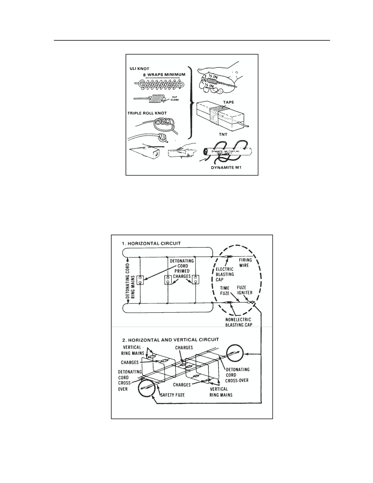
Demolitions and Obstacles
Figure H-1. Detonating cord priming
FIRING SYSTEMS
H-3. Firing systems may be electric or nonelectric. A dual-firing system is composed of two completely
separate systems. They may be dual electric, dual nonelectric, or a combination of electric and nonelectric.
Figure H-2 illustrates a combination dual-firing system.
Figure H-2. Combination dual-firing system
3 August 2009
FM 3-20.98
H-3
Appendix H
SAFETY
GENERAL SAFETY CONSIDERATIONS
H-4. The following safety considerations and procedures apply when scouts must operate with and around
explosives and demolitions:
z
Conduct CRM operations, completing risk assessments and identifying all hazards and control
measures. Refer to Appendix E of this manual.
z
Do not attempt to conduct a demolitions mission if you are unsure of demolition procedures;
review references or get assistance.
z
Do not let inexperienced personnel handle explosives.
z
Avoid dividing responsibility for demolition operations.
z
Use the minimum number of personnel necessary to accomplish the demolition mission.
z
Take your time when working with explosives; make your actions deliberate.
z
Post guards to prevent access inside the danger radius.
z
Maintain control of the blasting machine or initiation source.
z
Use the minimum amount of explosives required to accomplish the mission while keeping
sufficient explosives in reserve to handle any possible misfires.
z
Maintain accurate accountability of all explosives and accessories. Always store blasting caps
separately and at a safe distance from other explosives.
z
Ensure that all personnel and equipment are accounted for before detonating a charge.
z
Ensure that you give warnings before initiating demolitions; give the warning “FIRE IN THE
HOLE!” three times.
z
Guard the firing points.
z
Assign a competent safety officer for every demolition mission.
z
Dual-initiate all demolitions, regardless of whether they are single- or dual-primed.
z
Avoid using deteriorated or damaged explosives.
z
Do not dismantle or alter the contents of any explosive material.
z
Avoid mixing live and inert (dummy) explosives.
z
Assess the environmental impact of all demolition operations according to the environmental
risk assessment procedures covered in Appendix E of this manual.
MINIMUM SAFE DISTANCES
H-5. To ensure safety in the employment of explosives, scouts must maintain a minimum safe distance.
Table H-2 lists the minimum safe distances for personnel during detonation of explosives in the open.
H-4
FM 3-20.98
3 August 2009

Demolitions and Obstacles
Table H-2. Minimum safe distances for explosives
EXPLOSIVES (LB)
SAFE DISTANCE
EXPLOSIVES (LB)
SAFE DISTANCE
(M)
(M)
27 OR LESS
300
150
534
30
311
175
560
35
327
200
585
40
342
225
609
45
356
250
630
50
369
275
651
60
392
300
670
70
413
325
688
80
431
350
705
90
449
375
722
100
465
400
737
125
500
425
750
500
800
NOTES:
1. For explosives over 500 pounds, use the following formula to calculate the safe
distance:
Safe distance (meters) = 100 x
2. The minimum safe distance for personnel in a missile-proof shelter is 91.4 meters.
INDUCED-CURRENT DETONATION
H-6. Induced currents can prematurely detonate explosives. Figure H-3 lists the distances at which
transmitters can detonate explosives by transmitted induced currents.
H-7. Electric firing should not be performed within
155 meters
(504 feet) of energized power
transmission lines. When it is necessary to conduct blasting operations at distances closer than 155 meters,
nonelectric firing systems should be used or the power lines de-energized.
3 August 2009
FM 3-20.98
H-5
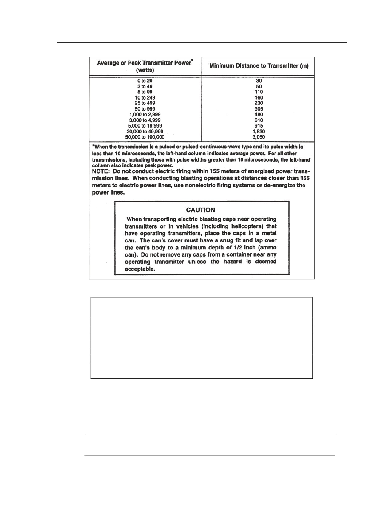
Appendix H
Figure H-3. Premature detonation by induced current
CAUTION
If electric blasting caps are to be transported near operating
transmitters or vehicles (including helicopters) in which a transmitter is
to be operated, the caps must be placed in a metal can. The cover of
the can must be snug and lap over the body of the can to a minimum
depth of 1/2 inch. Caps should not be removed from the container in
proximity of the operating transmitters. The metal container must have
metal-to-metal contact with the lid.
H-8. Misfires should be handled by the person who placed the charge. For safety purposes, allow 30
minutes before investigating the misfire on all nonelectric or buried charges. Aboveground misfires should
be blown in place by priming at least 1 pound of explosive and placing it as close as possible to the charge
without disturbing it. When dealing with buried misfires, remove excess earth, except for at least 1 foot of
earth around the charge. Then blow the charge in place with at least 2 pounds of explosive. Do not attempt
to move or disarm a misfire, and do not abandon misfired explosives.
Note. For complete procedures for handling misfires of electric and nonelectric systems, refer to
FM 3-34.214.
H-6
FM 3-20.98
3 August 2009
Demolitions and Obstacles
MODERN DEMOLITION INITIATOR FIRING SYSTEMS
H-9. Modern demolition initiators (MDI), a family of nonelectric blasting caps and associated items
described in Table H-3, have been used in the civilian sector for more than 20 years. The snap-together
components simplify initiation systems and some types of explosive priming. The MDI system was
developed to effectively replace electric demolition systems. It removes the requirement to dual-initiate
demolition systems except when there is a high probability of the system becoming cut. FM 3-34.214
provides more information on MDI.
H-10. Nonelectric priming with MDIs is safer and more reliable than the current nonelectric priming
methods. MDI blasting caps are factory-crimped to precut lengths of shock tube or time-blasting fuse.
Because the caps are sealed units, they are moisture-resistant and will not misfire in damp conditions. A
shock tube may be spliced using excess shock tube from an M12 or M13 or a precut splicing-tube splicing
kit. Every splice in a shock tube reduces the reliability of the priming system. Prime military explosives
with the MDI the same as with standard, nonelectric initiation systems. Use only high-strength MDI
blasting caps (M11, M14, M15) to prime explosive charges. M12 and M13 relay-type blasting caps do not
have sufficient power to detonate most explosives, although you can use all MDI blasting caps to initiate a
shock tube. Use only the M11, M14, or M15 blasting caps to initiate detonating cord or military explosives
directly.
WARNING
Use care when cutting and splicing the shock tube. When cutting
the shock tube, always tie an overhand knot in the left over shock
tube.
3 August 2009
FM 3-20.98
H-7
Appendix H
Table H-3. MDI components
COMPONENTS
DESCRIPTION
PACKAGING
M11
High-strength, nonelectric blasting cap, factory crimped to a
6/package, 10
30-ft length of shock tube—used to prime all standard military
packages per
explosives, including detonation cord, or to initiate the shock
box
tube of other MDI blasting caps. A red flag is attached one
meter from the cap, and a yellow flag is attached two meters
from the cap.
M12
8 spools/
Low-strength, nonelectric blasting cap1 , factory crimped to a
cardboard box,
500-ft length of shock tube—used as a transmission line from
6 boxes/
an initiator to another relay cap or to a high-strength, shock
packing box
tube blasting cap that initiates military explosives. Can
actuate up to five shock tubes held by the connector.
M13
4 spools/
Low-strength, nonelectric blasting cap1 , factory crimped to a
cardboard box,
1000-ft length of shock tube—used as a transmission line
6 boxes/
from an initiator to another relay cap or to a high-strength,
packing box
shock tube blasting cap that initiates military explosives. Can
actuate up to five shock tubes held by the connector.
M14
High-strength, nonelectric, delay blasting cap, factory crimped
1 package, 60
to a 7 ½-ft length of time-blasting fuse-instead of the usual
per wooden
yellow band every 18 in. a marker band and the minimum
box
burning time in minutes (from the band to the detonator) are
marked on the fuse. Used to detonate all standard military
explosives or initiate shock-tube blasting caps and detonating
cord approximately 5 minutes after ignition.
M15
30/box, 4
Nonelectric blasting cap, delay2—consists of two blasting
boxes/package
caps, factory crimped at each end of a 70-ft length of shock
, 6 packages/
tube. One blasting cap is low-strength to initiate another piece
wooden box
of shock tube, while the second is high-strength to initiate
other explosives. A red flag is attached one (1) meter from
the high-strength blasting cap, and a yellow flag is attached
two (2) meters from the low-strength cap. Used to create
staged detonations, as required for quarrying, ditching, and
cratering operations.
M9
Blasting cap and shock tube holder—clamping device used to
hold the shock tube’s branch lines secure to a high-strength
blasting cap of the M11 or M14. Can hold up to five shock
tubes and one (1) blasting cap. Can also connect an MDI
blasting cap to detonating cord.
M81
Time-blasting fuse igniter with shock tube capability—M81
5 paperboard
and M60 fuse igniters are almost identical except the plug
box/package, 6
packages/
and screw end cap are colored black on the M81.3
wooden box
Note. The M81 has a stronger primer than the M60.
1
Does not have enough output to initiate most military explosives.
2
Blasting caps are slightly larger that standard military blasting caps and will not fit into standard
cap wells.
3
The M60 fuse igniter will not reliably initiate the shock tube.
H-8
FM 3-20.98
3 August 2009
Demolitions and Obstacles
TYPES OF MDI FIRING SYSTEMS
H-11. With the introduction of MDI components, there will be two types of firing systems: a stand-alone
firing system and a combination firing system. Both systems can be emplaced as single- or dual-firing
systems. The choice of which system to use for a particular demolition mission is left to the experience of
the reconnaissance leader. The combination firing system, however, is the preferred method for reserved
demolition targets. See FM 3-34.214 for detailed instructions on both systems.
Stand-Alone System
Employment Considerations
H-12. The stand-alone firing system is one in which the initiation sets and transmission and branch lines
are constructed using only MDI components and the explosive charges are primed with MDI blasting caps.
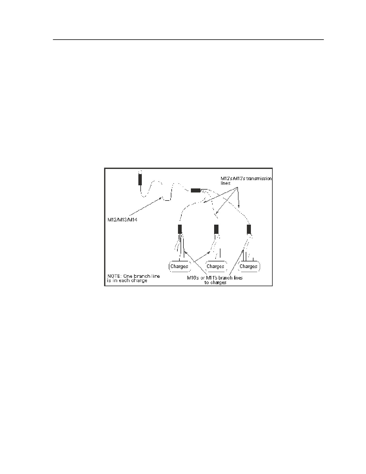
It is important to ensure that the firing system is balanced. All charges must have the same distance in
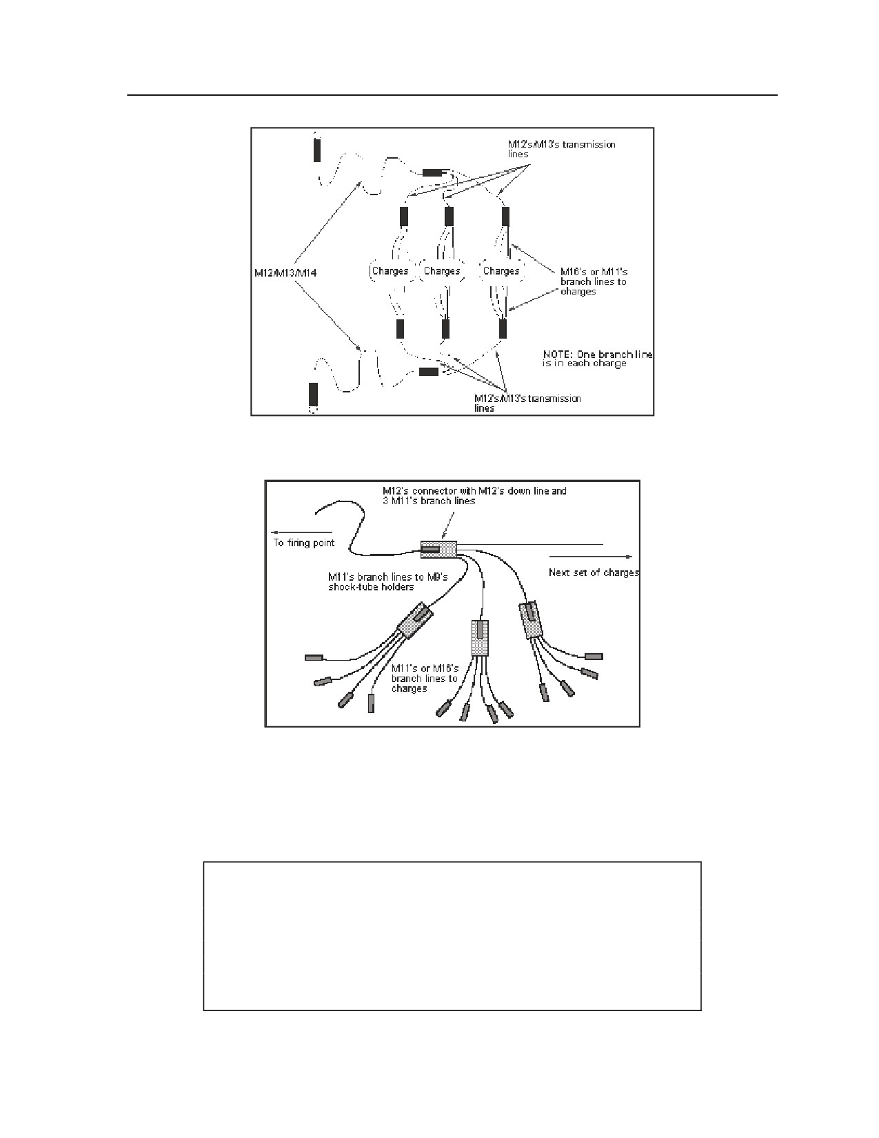
shock-tube length from the firing point to the charge. Figure H-4 shows the single-firing MDI system;
Figure H-5 shows the dual-firing MDI system; and Figure H-6 shows a branch-line array.
Figure H-4. MDI single-firing system (single-primed)
3 August 2009
FM 3-20.98
H-9
Appendix H
Figure H-5. MDI dual-firing system (dual-primed)
Figure H-6. Branch-line array (M11s or M16s)
H-13. The disadvantage of a single-firing system is that if the transmission line is cut, any charges down
line from the cut will not detonate. If there is a possibility of the transmission lines being cut (for example,
through artillery fires), a second firing system should be added as shown in Figure H-5. Note that the
charges in this case are now dual-primed. The transmission line is laid in the opposite direction of the first
transmission line to create a balanced system.
CAUTION
When making multiple shock tube installations, take care to protect the
shock tubes from the effects of nearby relay caps and charges. The
shrapnel produced by a cap or charge could easily cause a (partial or
complete) misfire. When there are many shock tubes involved in a
shot, place them carefully away from the junction.
H-10
FM 3-20.98
3 August 2009
Demolitions and Obstacles
H-14. Use the stand-alone MDI firing system for all types of demolition missions, including bridge
demolitions. The MDI firing system can be used to initiate reserved demolition targets; however, under
current internationally agreed-upon doctrine, charges cannot be primed with blasting caps until a change of
readiness from state 1 (safe) to state 2 (armed) is ordered. Priming every charge with MDI blasting caps at
this critical moment would take a considerable amount of time and be unacceptable to the maneuver
commander. Priming charges with detonating cord is the preferred method on reserved demolition targets.
Construction/Emplacement Procedures
H-15. Thoroughly reconnoiter the demolition site before emplacing explosive charges on the firing system.
Use the following steps to reconnoiter the site and emplace the explosives:
z
Step 1. Identify the firing point and observe the safe distances as listed in Table H-2 earlier this
appendix.
z
Step 2. Emplace and secure explosive charges on the target.
z
Step 3. Begin with the set of explosive charges farthest from the firing point, and place a
sandbag or other easily identifiable markers over the M12 blasting cap. Then unreel the M12’s
transmission line toward the next set of charges in the direction of the firing point. If the
distance between the sets of charges is less than 30 feet, use an M11.
z
Step 4. Place the shock tube of the first M12 into the blasting cap holder of the second M12’s
transmission line. This is done at the second set of charges.
Note. Do not close the hinged flap of the holder at this stage.
z
Step 5. Place a sandbag or another easily identifiable marker over the holder. Unreel the second
M12’s transmission line toward the third set of charges in the direction of the firing point.
z
Step 6. Repeat procedures steps 3 and 4 for each set of charges.
z
Step 7. Unreel the last transmission line to the firing point from the set of charges closest to it.
To achieve the necessary safe distance, you may need several M12s/13s.
z
Step 8. Lay out, at each set of charges, the M11 or M16 branch lines from the charges to be
primed toward the transmission lines blasting-cap holder. Ensure that when building the firing
system, it is a balanced system. The shock wave in the shock tube must travel the same distance
to all charges to effectively prevent a misfire. No more than five M11 or M16 branch lines can
be connected to the transmission line's blasting-cap holder. If there are more than five charges,
group the branch lines from the charges, and connect them to the M9 blasting-cap holder of
another M11 or M16 branch line. Connect the branch line to the transmission line’s blasting-cap
holder.
Note. Secure the transmission and branch lines by taping all the holders closed.
z
Step 9. Prime the explosive charges by inserting the blasting caps of the M11 or M16 branch
lines, using minimum personnel on the site.
z
Step 10. Visually inspect the firing system for possible misfire indicators.
z
Step 11. Return to the firing point and initiate the system using the procedures in FM 3-34.214.
Follow-up Considerations
H-16. After the charges have been successfully fired, the unit commander is responsible for ensuring
proper disposal of the residue. The used shock tube is nonrecyclable plastic and may be sent directly to an
approved landfill; however, the blasting-cap residue is considered hazardous waste and must be removed
from the shock tube and disposed of according to local policy. Commanders must coordinate with the
applicable local directorate
(engineering or public works) and/or the local Defense Reutilization and
Marketing Office for local disposal guidance and landfill information.
3 August 2009
FM 3-20.98
H-11
Appendix H
Combination Firing System
Employment Considerations
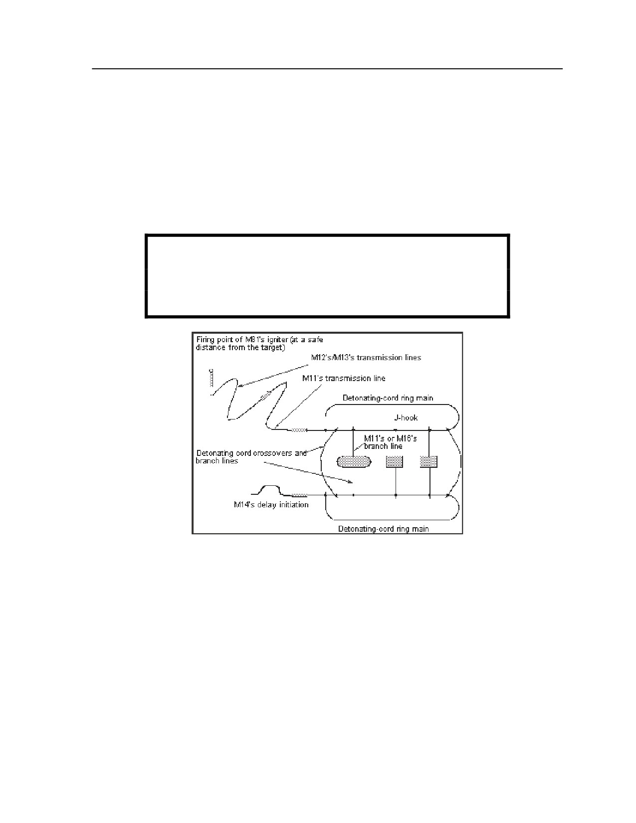
H-17. A combination firing system is one that consists of the MDI initiation set; either a detonating-cord
line or ring main; and branch lines that can be either MDI, detonating cord, or a mix of both. Figure H-7
shows a combination firing system.
H-18. Use the combination firing system (MDI and detonating cord) for all types of demolition missions. It
combines the advantages of MDI components with the simplicity and flexibility of detonating cord. The
combination firing system is the preferred method for reserved demolition targets, underwater operations,
and operations where subsurface-laid charges are used.
WARNING
Do not dispose of used shock tubes by burning them because of
potentially toxic fumes given off from the burning plastic.
Figure H-7. Combination firing system
(MDI and detonating cord; dual-primed)
Construction/Emplacement Procedures
H-19. Thoroughly reconnoiter the demolition site before emplacing explosive charges on the firing system.
Use the following steps to reconnoiter the site and emplace the explosives:
z
Step 1. Identify the firing point and observe the safe distances as given in Table H-2 earlier this
appendix.
z
Step 2. Emplace and secure the explosive charges on the target. If priming with MDI, wait until
step 6.
z
Step 3. Construct detonating-cord line or ring mains according to procedures in FM 3-34.214.
z
Step 4. Cover the blasting cap of the M12/13 transmission line with a sandbag or another easily
identifiable marker at the connection between the detonating cord line or ring main to the MDI
initiation set. Unreel the M12/13 transmission line to the firing point. Observe the safe distances
given in Table H-2.
H-12
FM 3-20.98
3 August 2009
Demolitions and Obstacles
z
Step 5. Tie in any detonating-cord branch lines to the line or ring main. If priming with MDI,
clip the M11 or M16 branch lines to the detonating-cord line or ring main using the M11 or M16
J-hook. Use the following procedure:
Wrap the shock tube around and to the J-hook.
Pull the shock tube tight. This prevents the J-hook from slipping.
Clip the detonating cord line or ring main into the J-hook.
Lay out the M11 or M16 branch lines toward the charges.
z
Step 6. Prime the remaining charges by inserting the M11 or M16 blasting caps, using minimum
personnel on the site
z
Step 7. Lay out an M11 or M16 transmission line from the detonation-cord ring main to the
M12/M13 transmission line.
z
Step 8. Attach the M11 or M16 to the holder on the M12/M13 transmission line and tape to secure.
z
Step 9. Attach an M9 holder on the M11 or M16 transmission line cap and tape.
z
Step 10. Loop, secure, and tape the detonating cord line of the ring main in the M9 blasting cap
holder that is attached to the M11 or M16 transmission line.
z
Step 11. Perform a visual inspection of the entire firing system for any flaws that might cause a
misfire.
z
Step 12. Return to the firing point and initiate the system using the procedures in FM 3-34.214.
Follow-up Considerations
H-20. After the charges have been successfully fired, the unit commander is responsible for ensuring
proper disposal of the residue. The used shock tube is nonrecyclable plastic and may be sent directly to an
approved landfill; however, the blasting cap residue is considered hazardous waste and must be removed
from the shock tube and disposed of according to local policy.
Splicing the Shock Tube
General Considerations
H-21. MDIs are extremely reliable because all of the components are sealed. Unlike standard nonelectric
priming components, they cannot be easily degraded by moisture. Cutting the shock tube makes the open
ends vulnerable to moisture. Dampening the explosive film on the inside of the shock tube will stop a
detonation from going beyond such a damp spot. Use care when cutting and splicing the shock tube. When
cutting the shock tube, always tie an overhand knot in the leftover shock tube. Use splicing to repair a
break in the shock tube of a transmission or branch line (caused, for example, by shell fragments from
artillery fires) or to extend the shock tube of another MDI blasting cap; but only when necessary. This is
done by using excess shock tube from an M12 or M13 shock-tube blasting cap when the entire length is
not needed.
H-22. Every splice in the shock tube reduces the reliability of the firing system. Keep the number of splices
in a shock-tube line to as few as practicable. Unless splicing is absolutely necessary, use of a full, sealed
MDI component is recommended.
Note. Do not splice the shock tube while conducting water or diving demolition missions.
Splicing Procedures
H-23. The following is the proper splicing procedure for the shock tube:
z
Use a sharp knife or razor blade to cut about 3 feet from the previously cut-off end of leftover
shock tube, whether or not it was knotted according to the guidance above.
z
Immediately seal off the shock tube remaining on the spool by tying a tight overhand knot in the
cut-off end. Cut the metal seal off the end of the shock-tube blasting cap to be extended. Repair
a break in the shock tube by cutting it 3 feet on both sides of the break. Use a minimum 4-foot
length of shock tube to repair the break.
3 August 2009
FM 3-20.98
H-13
Appendix H
z
Tie loosely the two shock-tube ends to be spliced together in an overhand knot. Leave at least 2
inches free at the end of each shock tube beyond the knot. Pull the shock tubes lightly to tighten
the knot, but not so tight as to significantly deform the shock tube in the knot.
z
Push one of the free shock-tube ends to be spliced firmly into one of the precut splicing tubes at
least l/4 inch. Push the other shock-tube end firmly into the other end of the splicing tube at least
l/4 inch. It is not necessary for the two ends of the shock tube meet; the detonation wave in the
shock tube will still generate over a small gap (of up to six inches).
Safety Considerations
H-24. When conducting training and missions with MDIs, follow the general safety considerations for
demolitions outlined in FM 3-34.214 and AR 385-63.
H-25. Because MDI components are delivered from the factory pre-crimped, they are more reliable and
safer to handle and use than the current standard military blasting caps. During testing of the MDI
components, it has been found that the blasting caps always function correctly if the shock tube is properly
initiated. Test results show that misfires occur only when—
z
The M81 fuse igniter is not properly connected to the shock tube before initiation.
z
The shock tube is cut by shrapnel during the initiation process.
z
The shock tube is incorrectly inserted into the holders on the M12 or M13 blasting caps or into
the M9 holder.
z
The shock tube is cut using crimpers.
CAUTION
Taping two cut ends of the shock tube together does not make a
reliable splice.
WARNING
Use of MDIs is not authorized for belowground or internal
charges.
H-26. Transportation and storage of blasting caps require special consideration. When transporting or
storing MDI blasting caps, do not mix them with other explosives. The caps must be placed in a suitable
container or in a separate vehicle.
MDI Misfire Clearing Procedures
H-27. In most misfires of shock tube blasting caps, which are nonelectric, these standard rules apply:
z
If the primer in the M81 does not fire (the most common problem), recock the M81 by pushing
in on the pull rod to reset the firing pin, and then actuate the igniter again. If two or three retries
result in a nonfiring, cut the shock tube, replace the igniter with a new one, and repeat the firing
procedure.
z
If the M81 fires and blows the shock tube out of its securing mechanism without it firing, cut
about 3 feet from the end of the shock tube, replace with a new igniter, and repeat the firing
procedure.
H-14
FM 3-20.98
3 August 2009
Demolitions and Obstacles
z
If the M81 appears to have functioned properly but the charge did not fire, cut a 1-foot section
from the shock tube starting 6 inches from the igniter. Hold the 1-foot piece of shock tube so
one end is over your palm; gently blow through the other end. If a fine powder comes out from
the shock tube, it has not fired. Install a new igniter on the freshly cut end of the priming shock
tube and repeat the firing procedure. If no fine powder comes out from the shock tube or the
shock tube was heard to fire or its flash was seen, wait for 30 minutes before moving downrange
to check the components in the firing system.
z
After waiting 30 minutes, proceed downrange and check all components in the firing system.
The most likely cause of a misfire is the incorrect placement of the shock tube in the plastic
connectors of the M12/13s or the M9 holder. If incorrect placement was the problem, replace the
fired section and properly connect and refire the device.
z
If the first component of the firing train did not fail, check out each succeeding component until
you find the one that failed. Replace the failed or fired relay components back to the initiating
site and refire.
z
If the final high-strength blasting cap seems to be the failed component, replace it if it is easily
accessible. However, if it is used to prime an explosive charge, do not disturb it. Place a new,
primed 1-pound explosive charge next to the misfired charge and detonate it when it is safe.
EXPLOSIVE CHARGES
FUNDAMENTALS
H-28. The amount of explosive used in any demolition project is determined by the demolition charts. The
following critical factors apply:
z
Type and strength of material. A demolition target may be constructed of timber, steel, or
other material. Concrete reinforced with steel increases the strength of the target.
z
Size and shape of target. Large targets, such as concrete piers and steel I-beams, may be
attacked more economically using multiple charges rather than a single charge.
z
Desired demolition effect. Consider the extent of demolition and other desired effects. For
example, in constructing an abatis, consider which direction the trees should fall.
z
Type of explosive. All charts in this chapter reflect the number of M112 (1¼-pound) blocks of
C4 to be used.
z
Size and shape of charge. Use the demolition charts in this chapter to calculate the amount of
explosive needed. When external charges are used without special placement techniques, a flat,
square charge with a thickness-to-width ratio of 1-to-3 or more will give acceptable results.
z
Charge placement. For cratering, place charges in holes below the ground. For breaking or
collapsing stone or concrete, locate charges on the surface or in boreholes. For cutting timber,
tie charges on the outside surface or place them in boreholes, whichever is more practical.
Fasten charges to the target by wire, adhesive compound, tape, or string. Prop charges against
the target with a frame made of scrap wood or metal or other available materials.
z
Method of initiation. The method of initiation is not critical except for special types of charges,
such as shaped charges or diamond charges.
z
Method of tamping. Detonating an explosive produces pressure in all directions. If the charge
is not completely sealed or confined or if material surrounding the explosive is not equally
strong on all sides, the explosive force will escape through the weakest point. To keep as much
explosive force as possible on the desired objective, pack the material around the charge. This
material is called tamping material; the process is tamping.
H-29. For the most destructive effect, an explosive charge must be of the size and shape that best fits the
target; it must be detonated in close contact with the target. Any significant air or water gap between the
target and the explosive will lessen the force of the shock wave. Several types of charges, such as sheet
explosives or plastic explosives, can be cut or molded to fit odd-shaped targets.
3 August 2009
FM 3-20.98
H-15
Appendix H
H-30. Whenever possible, place explosive charges to act on or through the smallest or weakest part of the
target. Internal charges produce the greatest destructive effect for the least amount of explosive. Internal
charges are placed in boreholes in the target. They are confined by tightly packed sand, wet clay, or other
material. This is called stemming. Tamp and pack the stemming material against the explosive to fill the
hole to the surface.
H-31. Place external charges on the surface of the target. Tamp the charges by covering them with packed
sand, clay, or other dense material. This increases their destructive effect. Tamping may be loose or in
sandbags. To be most effective, the thickness of the tamping should at least equal the breaching radius.
Small breaching charges on horizontal surfaces are sometimes tamped by packing several inches of wet
clay or mud around them. This process is called mudcapping.
SELECTION AND CALCULATION OF CHARGES
H-32. Use the six-step, problem-solving format below for all charge calculations. This format is used to
determine the weight (P) of the explosives required for a demolition task in pounds of TNT. If using an
explosive other than TNT, adjust P accordingly by dividing P for TNT by the relative effectiveness (RE)
factor of the explosive you plan to use (see Table H-1).
z
Step 1. Determine the critical dimensions of the target.
z
Step 2. Calculate the weight of a single charge of TNT by using the appropriate demolition
formula.
z
Step 3. Divide the quantity of explosive by the RE factor. Skip this step if using TNT.
z
Step 4. Determine the number of packages of explosive for a single charge by dividing the
individual charge weight by the standard package weight of the chosen explosive. Round this
result to the next higher, whole package. Use volumes instead of weights for special-purpose
charges (ribbon, diamond, saddle, and similar charges).
z
Step 5. Determine the number of charges based on the targets.
z
Step 6. Determine the total quantity of explosives required to destroy the target by multiplying
the number of charges (step 5) by the number of packages required per charge (step 4).
Formula
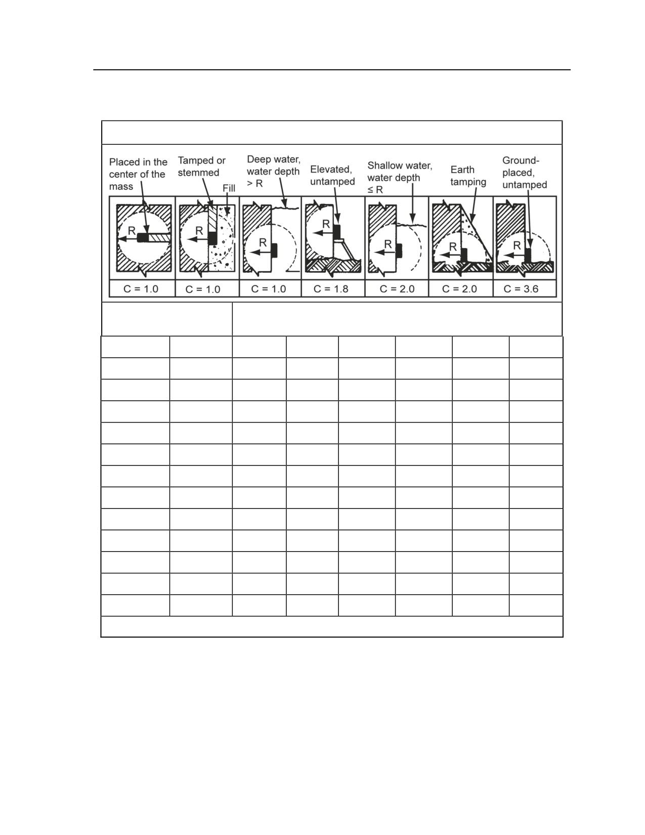
H-33. The formula P = R3KC is used to determine the size of the charge required to breach concrete,
masonry, rock, or similar material where—
z
P = TNT required (in pounds).
z
R = breaching radius( in feet).
z
K = material factor, which reflects the strength, hardness, and mass of the material to be
demolished.
z
C = tamping factor, which depends on the location and tamping of the charge.
Breaching Charge Tables
H-34. To use the tables for calculating breaching charges (see Tables H-4 through H-7), determine the type
of material in the object you plan to destroy. If in doubt, assume the material to be the stronger type. The
four tables cover breaching charges to be used in destroying the following materials:
z
Reinforced concrete (see Table H-4).
z
Dense concrete or first-class masonry (see Table H-5).
z
Ordinary masonry, hardpan, shale, rock, good timber, ordinary concrete, or earth construction
(see Table H-6).
z
Earth (see Table H-7).
H-16
FM 3-20.98
3 August 2009
Demolitions and Obstacles
Table H-4. Breaching charges for reinforced concrete
Placement Methods
Reinforced Concrete
Packages of M112 (Composition C4)
Thickness (ft)
2.0
1
5
5
9
10
10
17
2.5
2
9
9
17
18
18
33
3.0
2
13
13
24
26
26
47
3.5
4
21
21
37
41
41
74
4.0
5
31
31
56
62
62
111
4.5
7
44
44
79
88
88
157
5.0
9
48
48
85
95
95
170
5.5
12
63
63
113
126
126
226
6.0
13
82
82
147
163
163
293
6.5
17
104
104
186
207
207
372
7.0
21
111
111
200
222
222
399
7.5
26
137
137
245
273
273
490
8.0
31
166
166
298
331
331
595
Note. The results of all calculations for this table are rounded up to the next whole package.
3 August 2009
FM 3-20.98
H-17

Appendix H
Table H-5. Breaching charges for dense concrete or first-class
masonry
METHODS OF PLACEMENT
THICKNESS IN
C-4 M112 (1-1/4 LB BLOCKS)
METERS (FEET)
A
B
C
D
E
0.6 (2)
1
4
6
7
12
0.8
(2.5)
1
7
12
13
23
0.9 (3)
2
10
17
19
33
1.1
(3.5)
3
15
27
29
53
1.2 (4)
4
22
39
44
78
1.4
(4.5)
5
31
56
62
111
1.5 (5)
7
34
60
67
119
1.7
(5.5)
9
44
80
88
159
1.8 (6)
10
57
103
115
205
2.0
(6.5)
12
73
131
145
261
2.1 (7)
15
78
140
156
279
2.3
(7.5)
19
96
172
191
344
2.4 (8)
22
116
209
232
417
Table H-6. Breaching charges for ordinary masonry,
hardpan, shale, rock, good timber, ordinary concrete,
or earth construction
METHODS OF PLACEMENT
THICKNESS IN
C-4 M112 (1-1/4 LB BLOCKS)
METERS (FEET)
A
B
C
D
E
0.6 (2)
1
3
5
5
9
0.8
(2.5)
1
5
9
9
17
0.9 (3)
2
7
12
14
24
1.1
(3.5)
2
11
19
21
38
1.2 (4)
3
16
28
31
56
1.4
(4.5)
4
22
40
44
79
1.5 (5)
5
24
43
48
85
1.7
(5.5)
6
32
57
63
114
1.8 (6)
7
41
74
82
147
2.0
(6.5)
9
52
94
104
186
2.1 (7)
11
57
100
111
200
2.3
(7.5)
13
69
123
137
246
2.4 (8)
16
83
149
166
298
H-18
FM 3-20.98
3 August 2009

Demolitions and Obstacles
Table H-7. Breaching charges for earth structures
METHODS OF EMPLACEMENT
THICKNESS IN
C-4 M112 (1-1/4 LB BLOCKS)
METERS (FEET)
A
B
C
D
E
0.6 (2)
1
1
1
1
2
0.8
(2.5)
1
1
2
2
4
0.9 (3)
1
2
3
3
5
1.1
(3.5)
1
3
4
5
8
1.2 (4)
1
4
6
7
12
1.4
(4.5)
1
5
8
9
16
1.5 (5)
1
5
9
10
17
1.7
(5.5)
2
7
12
13
23
1.8 (6)
2
9
15
17
30
2.0
(6.5)
2
11
19
21
38
2.1 (7)
3
12
20
23
40
2.3
(7.5)
3
14
25
28
50
2.4 (8)
4
17
30
34
60
Correlating Thickness of Object and Placement of Charge
H-35. In deciding how to place the charge against the object, compare the method of placement with the
diagrams in Figure H-8. Use the letter matching the diagram to select the appropriate column in the
breaching charge tables. Then determine the thickness of the material. On the breaching charge tables, find
the intersection of these two factors (placement and thickness) to determine how many M112 (1¼-pound)
blocks of C4 it will take to destroy the object.
Note. Refer to Tables H-4 through H-7; as noted, the tables are based on the material to be
destroyed.
3 August 2009
FM 3-20.98
H-19
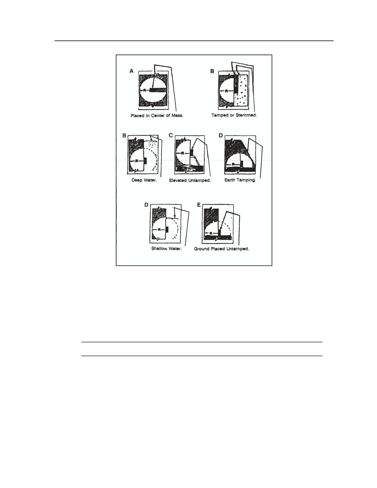
Appendix H
Figure H-8. Methods of placement for explosive charges
Number of Charges
H-36. Calculate the number of charges required to demolish a pier, slab, or wall using this formula:
N = W/2R
N = Number of charges
W = Width of pier, slab, or wall (in feet)
R = Breaching radius (in feet)
Note. The multiplier 2 in the formula is constant.
H-37. If the calculated value of N is between zero and 1¼, use one charge. If the value is between 1¼ and
2½, use two charges. If the value is greater than 2½, round it to the nearest whole number.
PLACEMENT OF CHARGES
H-38. For best results, arrange the charges in a flat square shape with the flat side toward the target. The
first charge is placed in from one side of the target; the rest of the charges are spaced at a distance of 2R
apart. When breaching hard-surface pavements, use one M112 (1¼-pound) block of C4 for each 2 inches
of surface. If you are breaching concrete-beam bridges, breach each beam individually. Figure H-9 lists the
thickness of the charge relative to the number of charges used.
H-20
FM 3-20.98
3 August 2009
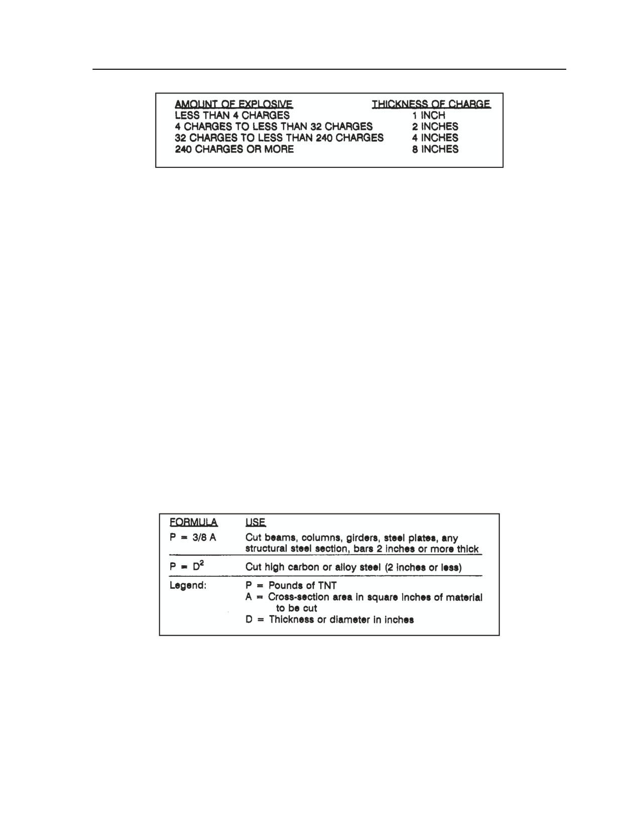
Demolitions and Obstacles
Figure H-9. Thickness of breaching charge
H-39. The positions available for placement of explosive charges on piers and walls are limited. Unless a
demolition chamber is available, place the charge (or charges) against one face of the target. A charge
placed above ground level is more effective than one placed directly on the ground. When several charges
are required to destroy a pier, slab, or wall and elevated charges are desired, they are distributed equally at
no less than one breaching radius above the base of the object to be demolished. This method makes best
use of the shock wave of the blast. If time permits, tamp all charges thoroughly with damp soil or filled
sandbags. Tamping must be equal to or greater than the breaching radius. For piers, slabs, or walls that are
partially submerged in water, place charges equal to or greater than the breaching radius below the
waterline, if possible.
STEEL-CUTTING CHARGES
H-40. In the employment steel-cutting charges, the type of explosive is critical to success. Confinement or
tamping of the charge is rarely practical or possible. Placement of the charge in direct contact with the
target is more important with steel than with other materials.
H-41. Select steel-cutting charges for their cutting effect and adaptability to placement. The M112 block
(C4) is a highly adaptable explosive. Its size and shape are suitable for most steel-cutting operations, and it
can be used without cutting or reshaping. In addition, the M112 block adapts well to steel targets because
of the adhesive compound on one face, which allows it to be affixed securely to the target.
Amount of Charge
H-42. The amount of steel-cutting charge to be used depends on the type and size of steel and the kind of
charge to be used. Figure H-10 shows formulas for the use of TNT in steel-cutting operations. Table H-8
lists the amount of C4 explosive required in steel-cutting operations.
Figure H-10. Formulas for use of TNT in steel-cutting charges
3 August 2009
FM 3-20.98
H-21

Appendix H
Table H-8. Amount of C4 (M112) required
to cut steel sections
C-4 M112 (1-1/4 LB BLOCKS) FOR RECTANGULAR STEEL SECTIONS OF GIVEN
WIDTH
DIMENSIONS
OF
THICKNESS OF SECTION IN CM (IN)
SECTION
IN CM (IN)
0.6
1.0
1.3
1.6
1.9
2.2
2.5
3.1
3.5
3.8
(1/4)
(3/8)
(1/2)
(5/8)
(3/4)
(7/8)
(1)
(1-1/4)
(1-3/8)
(1-1/2)
5.1 (2)
1
1
1
1
1
1
1
1
1
1
7.6 (3)
1
1
1
1
1
1
1
1
2
2
10.2 (4)
1
1
1
1
1
1
1
2
2
2
12.7 (5)
1
1
1
1
1
2
2
2
2
2
15.2 (6)
1
1
1
1
2
2
2
2
2
3
20.3 (8)
1
1
1
2
2
2
2
2
3
3
25.4 (10)
1
1
2
2
2
2
3
3
4
4
30.5 (12)
1
2
2
2
3
3
3
4
4
5
35.6 (14)
1
2
2
2
3
3
4
4
5
5
40.6 (16)
1
2
2
3
3
4
4
5
6
6
45.7 (18)
2
2
2
3
4
4
5
6
6
7
50.8 (20)
2
2
2
3
4
5
6
6
7
7
55.8 (22)
2
2
2
4
4
5
6
7
7
8
61 (24)
2
2
2
4
5
5
7
7
8
9
Rules of Thumb for Steel-Cutting Charges
H-43. In the following examples of steel-cutting situations, the required explosive is either TNT or plastic
explosive (the RE factor is not needed).
Rails
H-44. Cut rails at crossings, switches, or curves. Cut at alternate rail splices for a distance of 500 feet. The
rules of thumb are the following:
z
For rails less than 5 inches high, use ½ pound.
z
For rails 5 inches or higher, use 1 pound.
z
At crossings and switches, use 1 pound.
Cables, Chains, Rods, and Bars
H-45. To cut through these items, use the following rules of thumb:
z
Up to 1 inch in diameter, use 1 pound.
z
From 1 inch to 2 inches in diameter, use 2 pounds.
z
Over 2 inches in diameter, use the formula P = 3/8 A. (Refer to Figure H-11.)
Note. These guidelines apply to chains and cables that are under tension. Both sides of the chain
link must be cut.
H-22
FM 3-20.98
3 August 2009
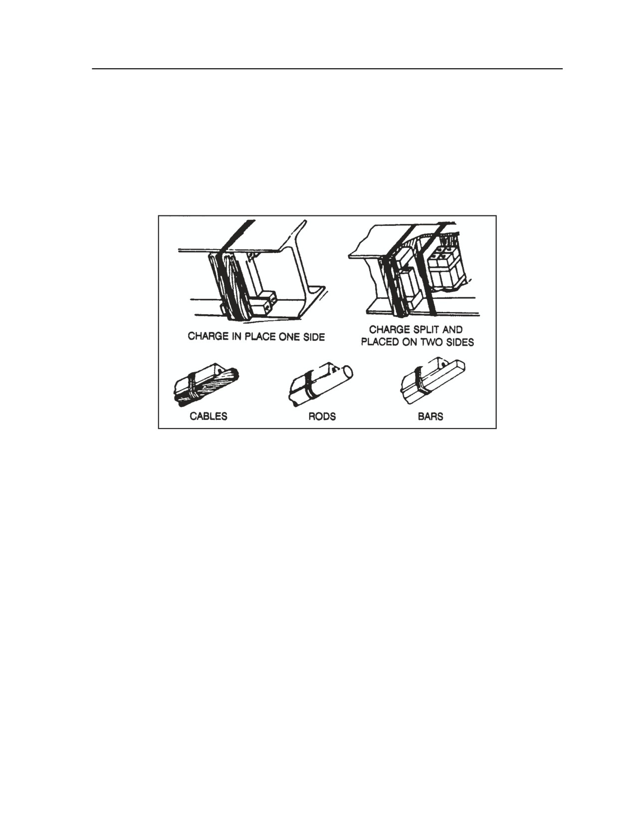
Demolitions and Obstacles
Placement Considerations
H-46. The size and type of steel section will determine the placement of the explosive charge. Cut extended
sections by placing all of the explosive on one side of the section along the proposed line of rupture. In
some steel trusses with individual members fabricated from two or more primary sections (such as angle
irons or bars separated by spacer washers or gusset plates), place the charge with opposing portions offset
the same distance as the thickness of the section being cut. This will produce a shearing action. Heavier I-
beams, wide flange beams, and columns can also require auxiliary charges. Never place the charges
directly opposite each other because this tends to neutralize the explosive effect.
H-47. Figure H-11 illustrates placement of a charge for cutting steel members and railroad rails.
Figure H-11. Placement of charges on steel members
Built-up Members
H-48. Built-up members frequently have an irregular shape, making it difficult to obtain close contact
between the explosive charge and a sufficient portion of the surface. If it is impractical to distribute the
charge properly to obtain close contact, increase the amount of explosive.
Irregularly Shaped Steel
H-49. Composition C4 is effective for cutting irregularly shaped steel because it can be easily molded or
pressed into place to give maximum contact. The M112 block explosive has an adhesive coating on one
side, which makes placement easier.
Precautions
H-50. Place the steel-cutting charge on the same side as the firing party because explosive charges throw
steel fragments (missiles) long distances at high velocities.
BRIDGE ABUTMENT DESTRUCTION
H-51. Procedures for destroying bridge abutments vary depending on the thickness of the abutment. Refer
to Figure H-12 for an illustration of charge placement.
3 August 2009
FM 3-20.98
H-23
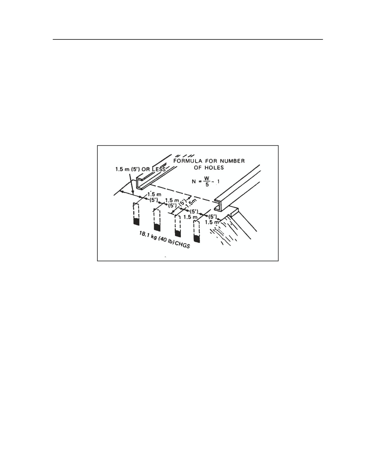
Appendix H
Thickness of 1.5 Meters (5 Feet) or Less
H-52. Beginning 1.5 meters (5 feet) in from one side of the road, place 18.1 kilograms (40 pounds) of
cratering charges in holes that are 1.5 meters (5 feet) deep, 1.5 meters (5 feet) on centers, and 1.5 meters (5
feet) behind the river face of the abutment. If the abutments are over 6.1 meters (20 feet) high, add a row of
breaching charges on the river face of the abutment.
Thickness of 1.5 Meters (5 Feet) or More
H-53. Calculate charges using the breaching charge tables (see Tables H-4 through H-7) and information
provided earlier in this chapter. Place the charges against the rear face at a depth equal to the thickness of
the abutment and space them the same as other breaching charges. When the abutments are more than 6.1
meters (20 feet) high, add a row of breaching charges on the river face at the base of the abutment and fire
all charges simultaneously.
Figure H-12. Charge placement for bridge
abutment destruction
TIMBER-CUTTING CHARGES
H-54. Use composition C4 for untamped, concentrated, external charges because it can be easily tied or
fastened to the target. Because types of timber vary widely from locality to locality, it is impractical to try
to cut all kinds of timber with charges calculated from a single table. It may be necessary, therefore, to
make test shots to determine the size of charge needed to cut a specific type of timber. Table H-9 shows the
amount of M112 (1¼-pound blocks) C4 needed for the various sizes of timber. Figure H-13 provides
several formulas for determining timber-cutting charges and illustrates charge placement.
H-55. Place the charge in a borehole parallel to the greatest dimension of the cross section and tightly tamp
it with moist earth. If the charge is too large for one borehole, make two boreholes side by side in the
dimensional timber. For round timber, make two boreholes at approximate right angles to each other, but
do not intersect them (see Figure H-14). Tamp both boreholes and fire the charges simultaneously.
H-24
FM 3-20.98
3 August 2009
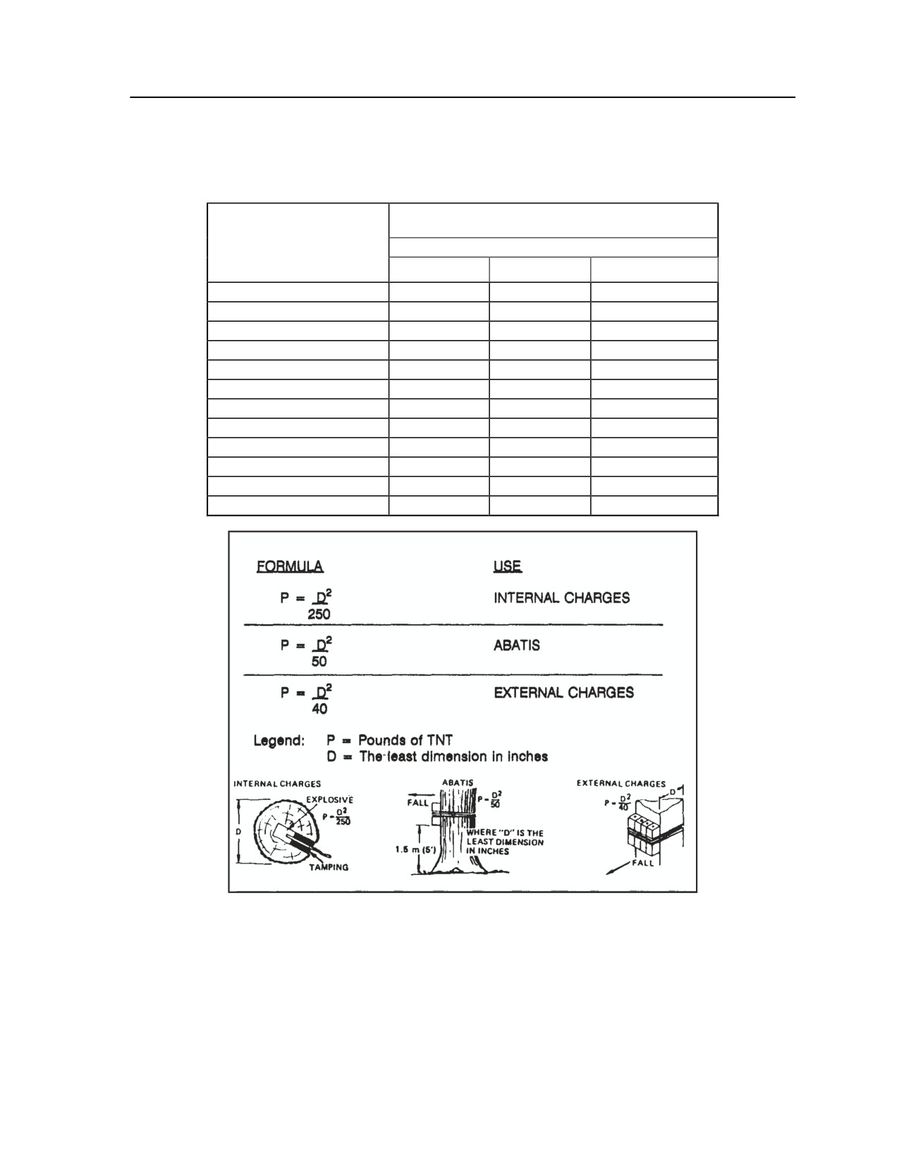
Demolitions and Obstacles
Table H-9. Amount of C4 (M112) required
for timber-cutting charges
EXPLOSIVE C4 M112 (11/4 - Pound Blocks
SMALLEST DIMENSION OF
TIMBER CM (IN)
TYPE OF CHARGE
INTERNAL
EXTERNAL
ABATIS
15.2 (6)
1
1
1
20.3 (8)
1
2
2
25.4 (10)
1
2
2
30.5 (12)
1
3
2
38.1 (15)
1
4
3
45.7 (18)
1
6
4
53.3 (21)
2
7
6
61 (24)
2
9
8
68.6 (27)
2
12
9
76.2 (30)
3
14
11
83.8 (33)
3
17
14
91.4 (36)
4
20
16
Figure H-13. Timber-cutting formulas and charge placement
3 August 2009
FM 3-20.98
H-25
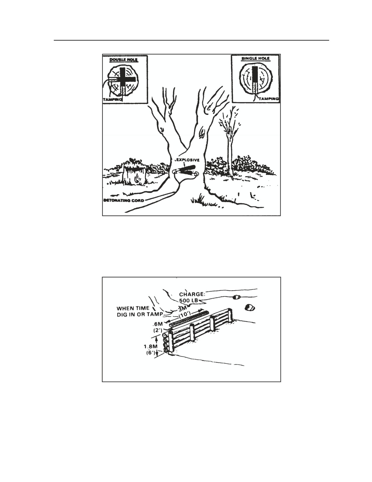
Appendix H
Figure H-14. Internal timber-cutting charges
OBSTACLE DESTRUCTION
H-56. The reconnaissance/scout platoon may be tasked to destroy obstacles. The illustrations in Figures H-
15 through H-19 show the recommended methods for explosives placement to achieve the greatest
destructive effect with various types of obstacles.
Figure H-15. Breaching of a backfilled log wall
H-26
FM 3-20.98
3 August 2009
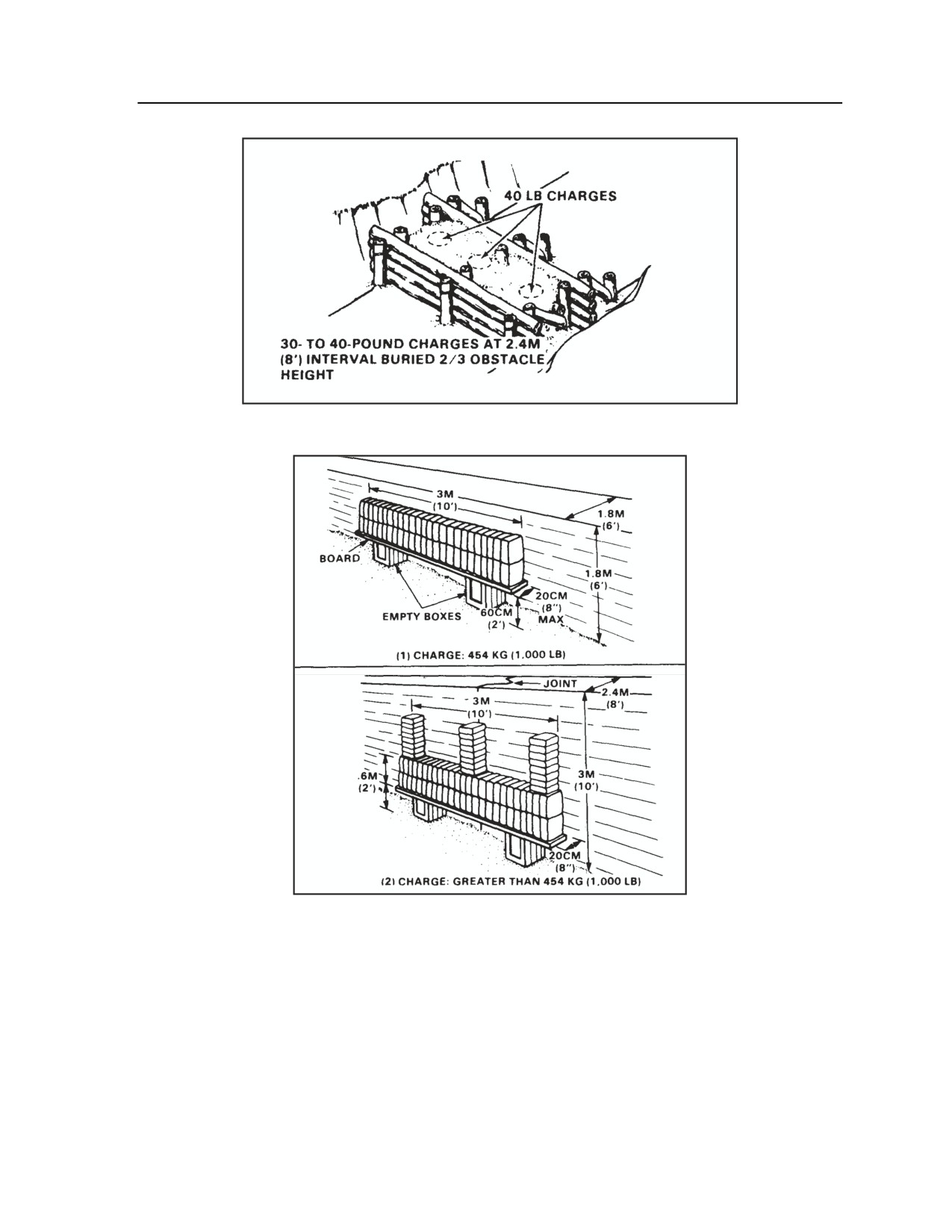
Demolitions and Obstacles
Figure H-16. Breaching of a log crib
Figure H-17. Placement of charges for breaching of walls
3 August 2009
FM 3-20.98
H-27
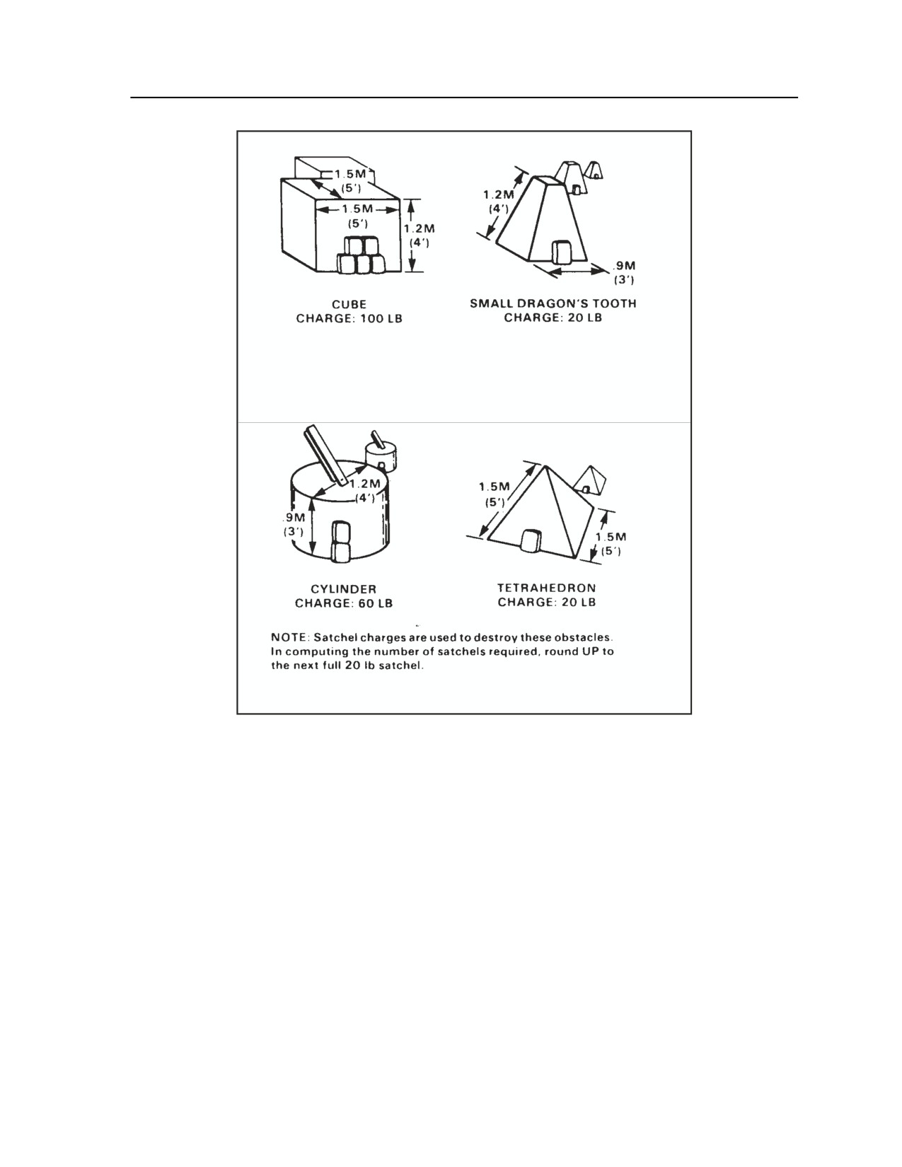
Appendix H
Figure H-18. Explosive packs required to destroy
typical small concrete obstacles
H-28
FM 3-20.98
3 August 2009
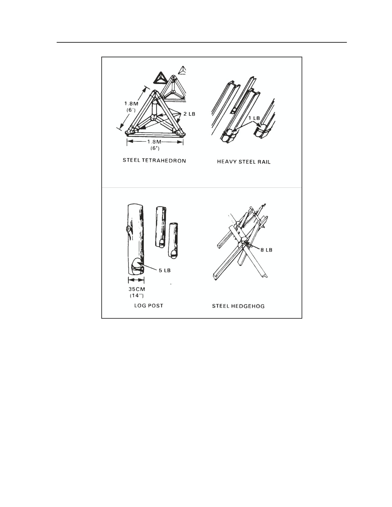
Demolitions and Obstacles
Figure H-19. Placement of charges for destruction
of steel and log obstacles
CRATERING CHARGES
H-57. The explanation and sketches in Figure H-20 includes explanations and illustrations for procedures
to be used in creating various types of road craters.
3 August 2009
FM 3-20.98
H-29
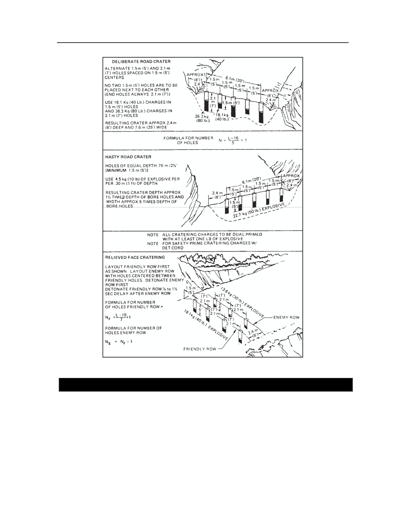
Appendix H
Figure H-20. Road cratering charges
SECTION II - MINES
H-58. This discussion provides examples of mines employed by U.S. forces, including the
reconnaissance/scout platoon. The discussion also examines the types of minefields the platoon may
encounter in the AO. It covers how to record minefields after they have been emplaced and how to mark
and record lanes that have been cleared through a minefield.
H-30
FM 3-20.98
3 August 2009
Demolitions and Obstacles
MINES EMPLOYED BY U.S. FORCES
H-59. Figure H-21 depicts various mines employed by the U.S. military, including the
reconnaissance/scout platoons. The information covers characteristics of mines and firing devices and
procedures for mine installation, arming, and disarming.
Figure H-21. U.S. mines
3 August 2009
FM 3-20.98
H-31
Appendix H
Figure H-21. U.S. mines (continued)
H-32
FM 3-20.98
3 August 2009
Demolitions and Obstacles
Figure H-21. U.S. mines (continued)
3 August 2009
FM 3-20.98
H-33
Appendix H
Figure H-21. U.S. mines (continued)
H-34
FM 3-20.98
3 August 2009
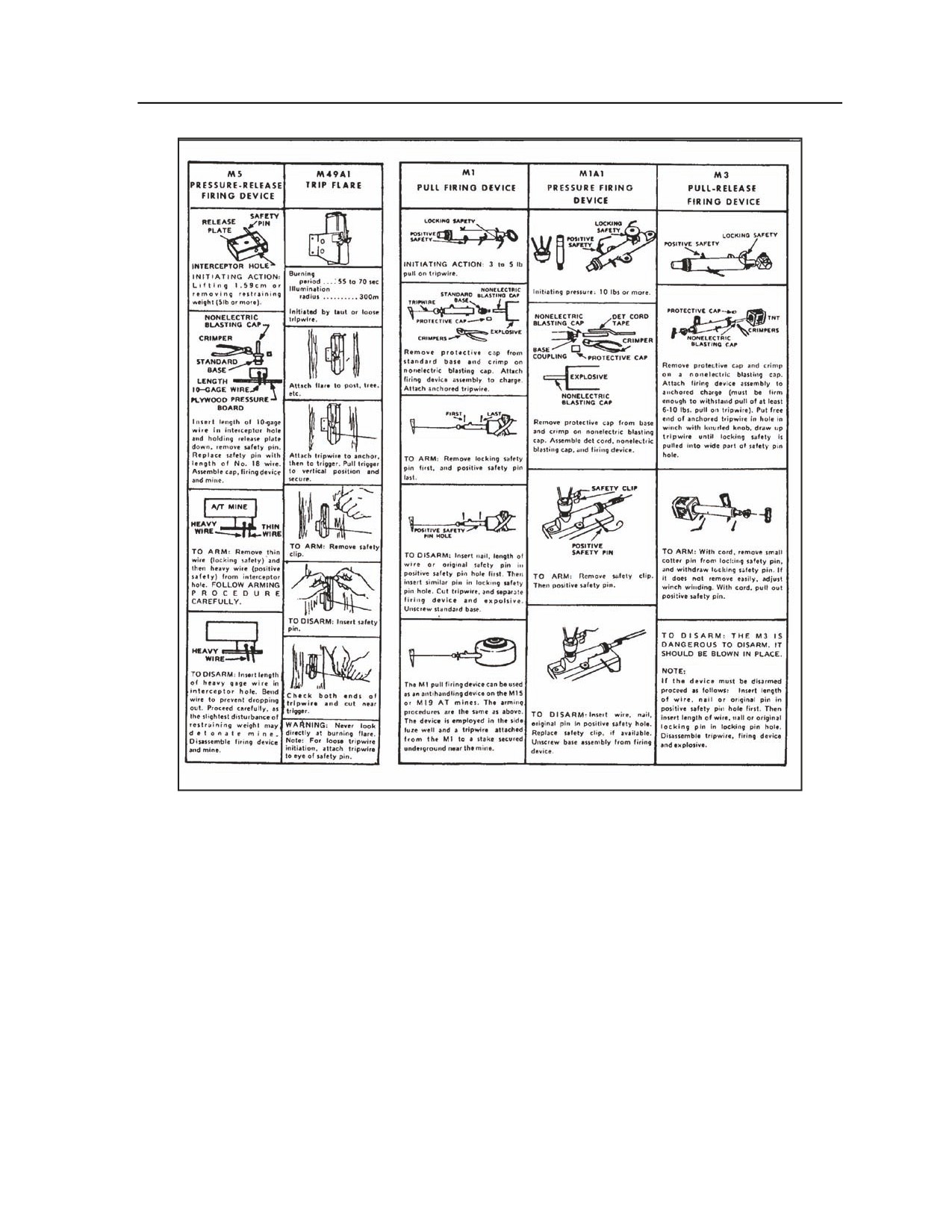
Demolitions and Obstacles
Figure H-21. U.S. mines (continued)
3 August 2009
FM 3-20.98
H-35
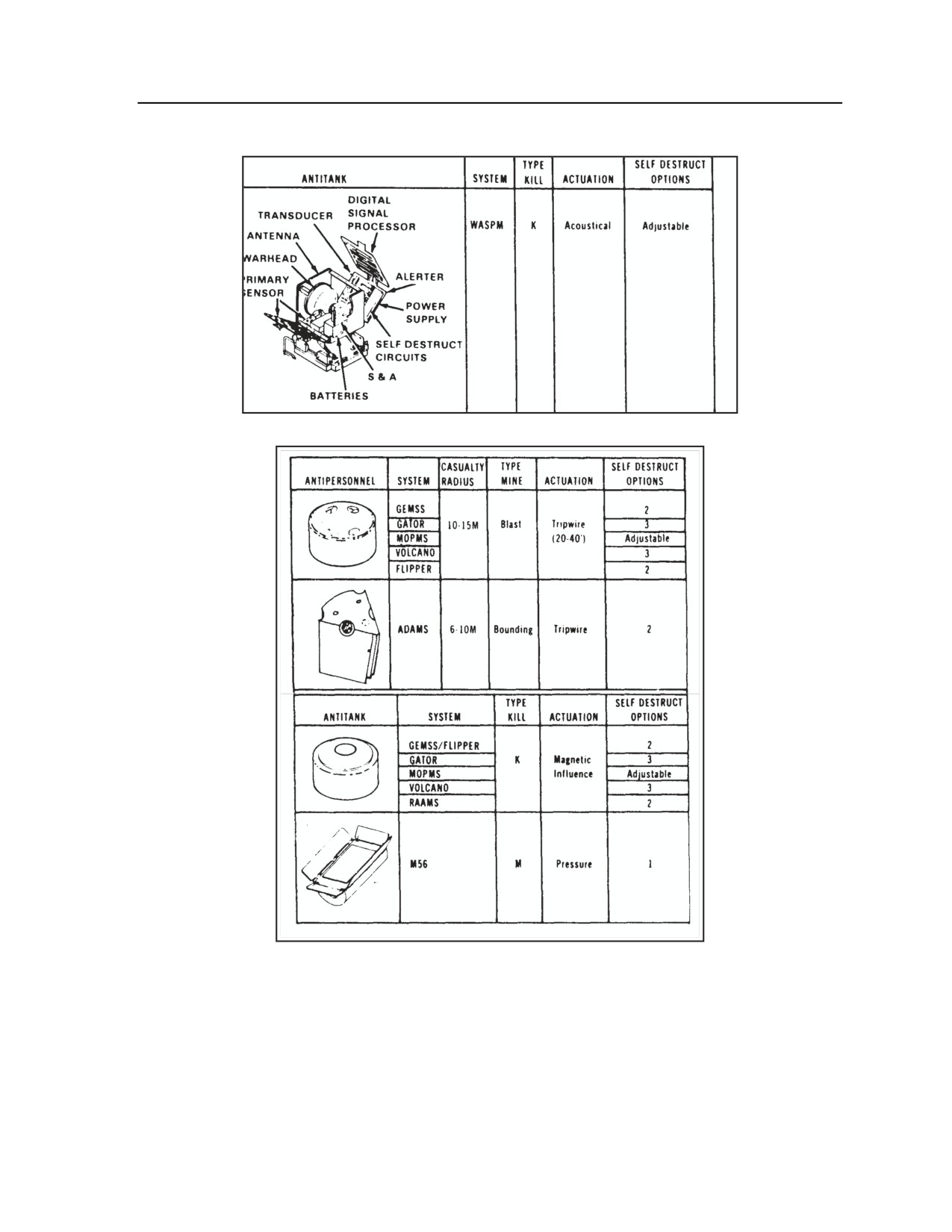
Appendix H
Figure H-21. U.S. mines (continued)
TYPES OF MINEFIELDS
H-60. The reconnaissance/scout platoons may employ or encounter one of four main types of minefields.
Refer to Table H-10 for a summary of characteristics and uses of these minefields.
H-36
FM 3-20.98
3 August 2009
Demolitions and Obstacles
Table H-10. Minefield types and characteristics
TYPE
DESCRIPTION
TACTICAL
REPORTS
RECORDS
MINES USED
AUTHORITY
USE
REQUIRED
REQUIRED
(Delegated
to)
**
Protective
Above-ground;
Aids in unit’s
Intention
DA Form
X
X
X
Brigade
random pattern;
local, close-in
1355-1 (to
commander
Hasty
Initiation
no antihandling
protection of
parent unit)
protective
(Battalion or
Completion
devices
defensive
company
perimeter
Change/
commander)
removal
Deliberate
Standard
Same as hasty
As above
DA Form
X
X
Division
protective
pattern; fenced
deliberate
(to author-
1355 (to
commander
and marked
minefield
izing HQ)
authorizing
(Installing
HQ)
commander)
Tactical
Standard or
As part of
As above
DA Form
X
X
X
Division
random pattern;
obstacle plan
1355 (to
commander
scatterable
authorizing
(Brigade
HQ)
commander)
Nuisance
Random
Enhance
As above
As above
X
X
X
Brigade
pattern; surface
obstacles;
commander
or buried
hinder use of
(Battalion
key areas
commander)
Phony
Same as live
Simulate other
Same as
Same as
Same as
minefield being
types of
simulated
simulated
simulated
simulated
minefields
minefield
minefield
minefield
Use the scatterable minefield report and records for all scatterable minefields (under “S” column).
**
The corps commander is the initial employment authority for all scatterable minefields (“S” column). Long self-
destruct minefields (more than 24 hours) may be delegated to division and brigade level. Short self-destruct
minefields (24 hours or less) may be delegated to battalion/task force level.
MINEFIELD EMPLACEMENT REQUIREMENTS
H-61. Of the four types of minefields, the reconnaissance/scout platoons will most frequently be tasked to
emplace a hasty protective minefield. It will rarely emplace a deliberate protective minefield. Scouts may
employ a row minefield and, occasionally, if time allows, a standard pattern minefield.
H-62. Emplacement of a row minefield (three rows, 60 meters by 100 meters, 100 AT mines) consumes
about 30 platoon minutes (30 scouts) if done by hand. This time does not include fuzing and uncrating of
the mines.
HASTY PROTECTIVE MINEFIELD
H-63. Hasty protective minefields are generally emplaced by small units at outposts, work sites, bivouac
areas, or ambush sites. The reconnaissance platoon may also use them to supplement manned weapons,
prevent tactical surprise, or provide early warning of enemy advances.
H-64. Mines should be readily detectable and removable. They should be sited across likely avenues of
approach and within range of organic weapons and visual observation. If the minefield includes M18A1
AP mines or will be employed for more than 72 hours, it should be marked by signs or fences or have
guards to warn friendly troops.
H-65. The hasty protective minefield must be recorded on DA Form 1355-1, which is illustrated in Figure
H-22. If the form is not available, improvise one. The unit that installs the minefield should warn adjacent
units and inform higher headquarters. This unit must either remove the field before leaving the area or
transfer the responsibility to the relieving unit commander. Refer to FM 3-34.210.
3 August 2009
FM 3-20.98
H-37
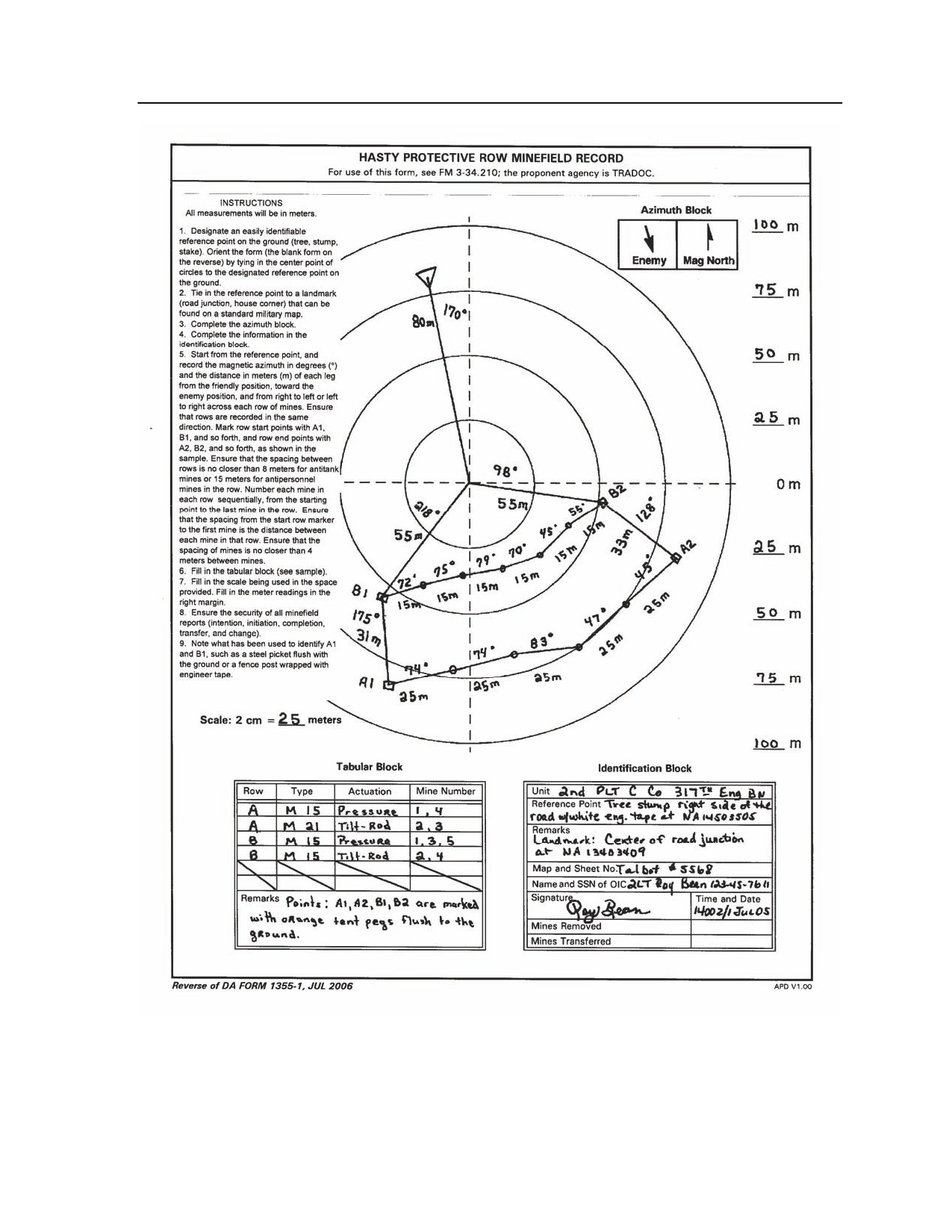
Appendix H
Figure H-22. Hasty protective row minefield record
H-38
FM 3-20.98
3 August 2009
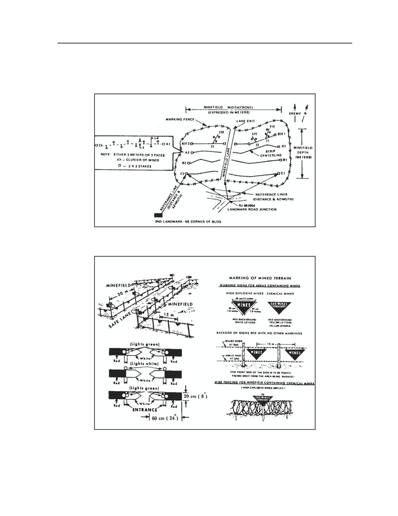
Demolitions and Obstacles
MINEFIELD MARKING
H-66. Figure H-23 shows a standard pattern minefield with appropriate markings. Figure H-24 illustrates
several methods of marking lanes through a minefield.
Figure H-23. Standard pattern minefield
(fenced, marked, and referenced)
Figure H-24. Standard rear area lane marking procedures
3 August 2009
FM 3-20.98
H-39
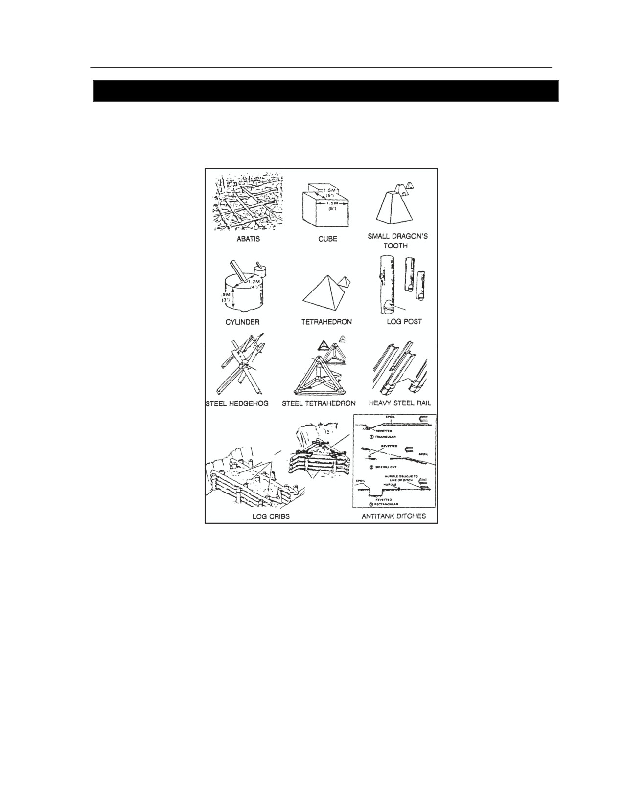
Appendix H
SECTION III - OBSTACLE CHARACTERISTICS AND REPORT FORMATS
OBSTACLE TYPES
H-67. Figure H-25 shows various obstacles that the reconnaissance platoon may encounter during combat
operations.
Figure H-25. Common obstacle types
REPORT FORMATS
OBSTACLE REPORT
H-68. Table H-11 shows a sample format for an obstacle report. For further information on reporting
procedures for obstacles, refer to Appendix A of this manual.
H-40
FM 3-20.98
3 August 2009
Demolitions and Obstacles
Table H-11. Obstacle report format
REPORT LINE
INFORMATION
ALPHA
Map sheets
BRAVO
Date-time group for observation of obstacle
CHARLIE
Location (grid reference)
DELTA
Type of obstacle
ECHO
Enemy elements -and/or weapons with coverage of the
obstacle (if applicable)
FOXTROT
Any other information that could affect breaching or
bypassing; for example, terrain restricts bypass or work
required (in personnel hours) to breach obstacle
DEMOLITION RECONNAISSANCE RECORD
H-69. When members of the platoon encounter an obstacle that may require demolition support, they
conduct a reconnaissance of the obstacle and surrounding area and complete DA Form 2203, Demolition
Reconnaissance Record. The form is then sent up the chain of command to the appropriate support unit for
evaluation, planning, and conduct of the demolition mission. Refer to FM
3-34.214 for additional
information on the preparation and use of DA Form 2203; the manual includes an example of the
completed form.
Note. DA Form 2203 consists of four pages. The first page lists general information about the
reconnaissance party and the obstacle (including map location information, description of the
demolition site, and nature of the proposed demolition), as well as detailed estimates for the
demolition in terms of materials, equipment, transport, personnel, and time requirements. The
second page provides space for additional information, while Page 3 contains space for a
general sketch of the demolition site and a sketch of the purpose of the proposed demolition
mission. The fourth page offers detailed instructions for completing the form.
SECTION IV - OBSTACLE/MINEFIELD TURNOVER
H-70. Once an obstacle group or minefield is completed, the emplacing unit may conduct turnover with
another unit. The turnover process ensures that the commander of the incoming unit is familiar with the
obstacle or minefield and understands his responsibilities concerning it. Turnover is conducted whether or
not there are lanes/gaps to be closed.
(Note. Minefield turnover is required in almost all tactical situations;
the time and the location for the turnover are established during initial coordination.)
TURNOVER PROCEDURES
H-71. A target prepared for demolition by engineers may be turned over to another unit for safeguarding or
execution. The following turnover procedures are followed:
z
The senior member of the emplacing unit
(normally an engineer squad leader) and the
demolition guard commander (normally a reconnaissance squad leader) will conduct face-to-
face coordination before the turnover if the tactical situation permits. This prior coordination
greatly aids and speeds the turnover process.
z
The senior member of the emplacing unit will require positive identification of the demolition
guard commander by means of sign/countersign or by personal recognition.
3 August 2009
FM 3-20.98
H-41
Appendix H
z
Once identification is established, the emplacing unit will give the demolition guard commander
a completed target folder for the target being turned over. The folder contains orders to the
demolition guard commander and the firing party commander. These orders must be signed and
thoroughly understood by the demolition guard commander.
SECTION IV - OBSTACLE/MINEFIELD TURNOVER
H-72. Once an obstacle group or minefield is completed, the emplacing unit may conduct turnover with
another unit. The turnover process ensures that the commander of the incoming unit is familiar with the
obstacle or minefield and understands his responsibilities concerning it. Turnover is conducted whether or
not there are lanes/gaps to be closed.
(Note. Minefield turnover is required in almost all tactical situations;
the time and the location for the turnover are established during initial coordination.)
TURNOVER PROCEDURES
H-73. A target prepared for demolition by engineers may be turned over to another unit for safeguarding or
execution. The following turnover procedures are followed:
z
The senior member of the emplacing unit
(normally an engineer squad leader) and the
demolition guard commander (normally a reconnaissance squad leader) will conduct face-to-
face coordination before the turnover if the tactical situation permits. This prior coordination
greatly aids and speeds the turnover process.
z
The senior member of the emplacing unit will require positive identification of the demolition
guard commander by means of sign/countersign or by personal recognition.
z
Once identification is established, the emplacing unit will give the demolition guard commander
a completed target folder for the target being turned over. The folder contains orders to the
demolition guard commander and the firing party commander. These orders must be signed and
thoroughly understood by the demolition guard commander.
z
The senior member of the emplacing unit will then describe the obstacle, in detail, to the
demolition guard commander.
z
Once the demolition guard commander fully understands his responsibilities and he (or the
firing party commander, if separately designated) is capable of executing the target, the
emplacing unit may depart to conduct further operations.
COORDINATION
H-74. In conducting coordination for obstacle/minefield turnover, scouts must cover the following items
with the other unit:
z
Intelligence.
Provide an update on enemy activity forward of the minefield.
Discuss expected enemy reconnaissance efforts.
Brief on local, friendly, and enemy situations.
z
Maneuver.
Discuss obstacle protection against enemy dismounted patrols.
Recommend that the other unit conduct security patrols to protect the minefield during
limited visibility.
Discuss fire control measures.
z
Mobility and survivability.
Discuss the obstacle's intended effect on enemy maneuver.
Discuss the minefield front and depth and walk/ride the minefield trace. Provide grid
coordinates of the minefield trace.
Discuss minefield composition.
H-42
FM 3-20.98
3 August 2009
Demolitions and Obstacles
Discuss friendly minefield marking.
Discuss lane/gap closure, if applicable. Confirm the signal or activity that will
trigger/initiate lane closure.
Train units on how to close lanes. This may mean training the unit on emplacing
conventional mines or using the MOPMS.
z
Fire support.
Update the other unit’s FIST on grid coordinates for the minefield trace.
Discuss indirect fires covering the minefield.
z
Sustainment. Provide mines/materials required to close lanes/gaps; ensure all necessary
materials are available and prepared.
z
C2.
Transfer graphics and documentation (minefield records, demolition-target folders, or other
written records).
Report completion of the turnover to the higher engineer and supported unit headquarters.
Complete an obstacle turnover report and submit it to higher headquarters.
Forward the written minefield report and record (using DA Form 1355 or DA Form 1355-
1) to the next higher commander common to both units.
SECTION V - OBSTACLE BREACHING CAPABILITIES
H-75. This section provides information on breaching capabilities. It will assist the reconnaissance or scout
platoon in determining what types of equipment, vehicles, and other assets can be used for certain
breaching situations. Also covered are the obstacle-crossing capabilities (trafficability and fordability) of
various U.S. and allied vehicles.
ACTIONS ON CONTACT (WITH OBSTACLES)
H-76. Use this format to conduct actions on contact with obstacles:
z
Reconnoiter the obstacle and report.
z
Seek a bypass.
z
If a bypass is impossible, attempt a breach.
z
As a last resort, force through the obstacle. All reconnaissance sections should have a chain saw
(issued or locally procured) for clearing roads wooden obstacles from roads or trails.
z
If the obstacle is covered by fire, use obscurants to conceal movement.
AN/PSS-12 MINE DETECTOR
H-77. The reconnaissance/scout platoons may use mine detectors such as the AN/PSS-12 to help detect
mines and clear lanes in minefields.
CHARACTERISTICS
H-78. The AN/PSS-12 mine detector (see Figure H-26) is a man-portable metallic mine-detection system
that is used to detect AT and AP land mines. Its search head contains two concentric coils—the
transmitting coil and the receiving coil. During operation, the transmitting coil is energized with electric
pulses to build up a magnetic field. The magnetic field induces currents in metal objects near the search
head, and the currents build up a magnetic field in the metal objects. Depending on the metal’s composition
and quantity, the magnetic field may be strong enough to be picked up by the receiving coil. Signals from
the receiving coil are processed in the AN/PSS-12’s electronics. When a signal is considered positive, the
electronic unit provides an audible alarm to the operator.
3 August 2009
FM 3-20.98
H-43
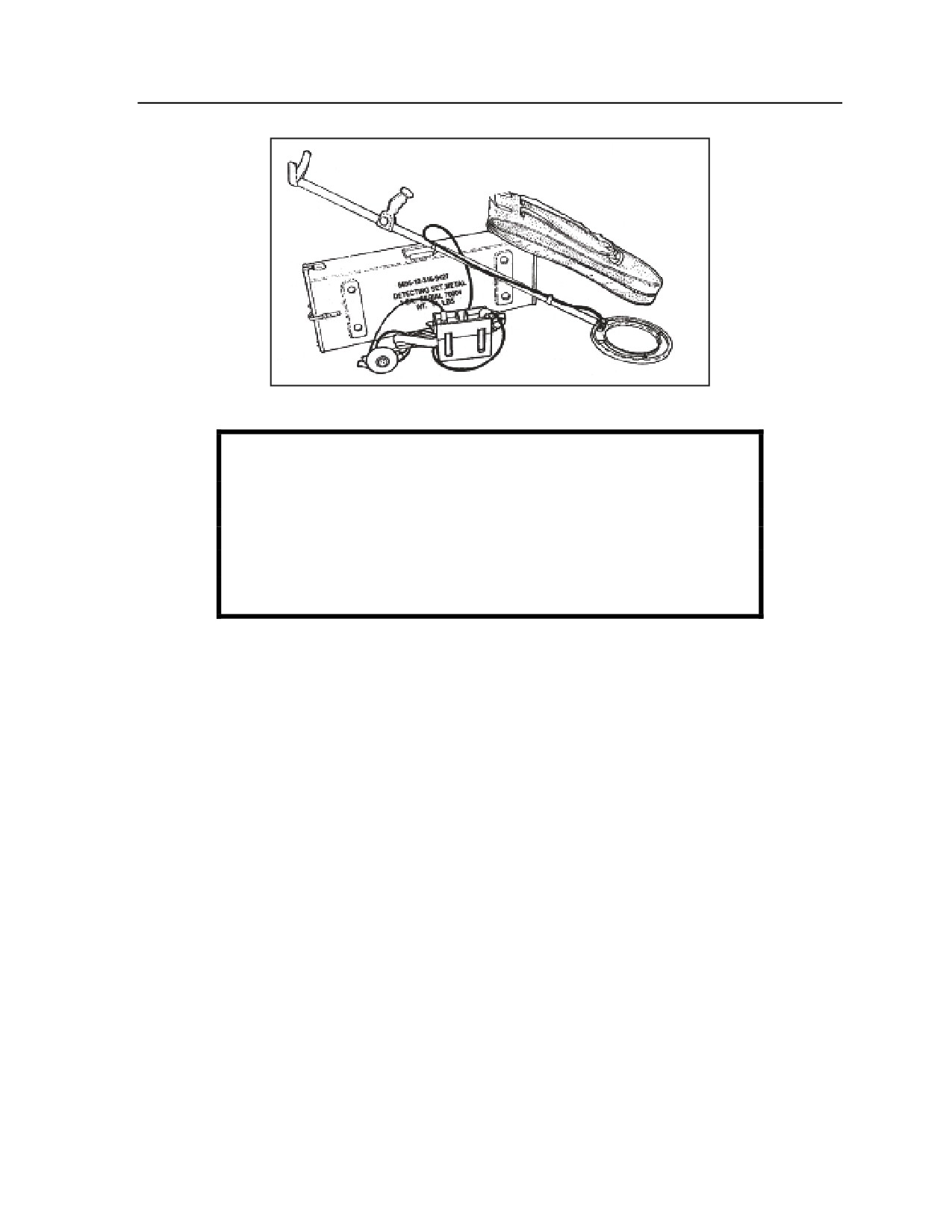
Appendix H
Figure H-26. AN/PSS-12 metallic mine detector
WARNING
Users must keep in mind that magnetic detection is effective only
when there is a sufficient amount of alloy in the mine to trigger an
alarm from the detector.
The detector’s sensitivity control may require frequent
adjustment during operation.
SEARCH METHODS
H-79. Use the following procedures and guidance in searching for mines using the AN/PSS-12:
z
Move the search head in sweeping motions a maximum of 5 centimeters above the ground.
Sweeping speed should be approximately 0.3 meter per second.
z
Listen for an audible tone indicating that the inner ring of the magnetic search head is over a
metal object. The intensity of the tone depends on the size, the shape, the content, the depth, and
the position of the object.
z
Make an X-pattern sweeping movement (Figure H-27) across the area when a tone is heard. The
tone will be loudest when the search head is immediately above the object.
z
For small, horizontal metal pins, the tone will be louder when the inner ring is near the pin
rather than when the pin is in the center of the ring.
z
If you are searching for large, metal objects, detecting and localizing is faster when the
sensitivity control is turned down (counterclockwise).
H-44
FM 3-20.98
3 August 2009
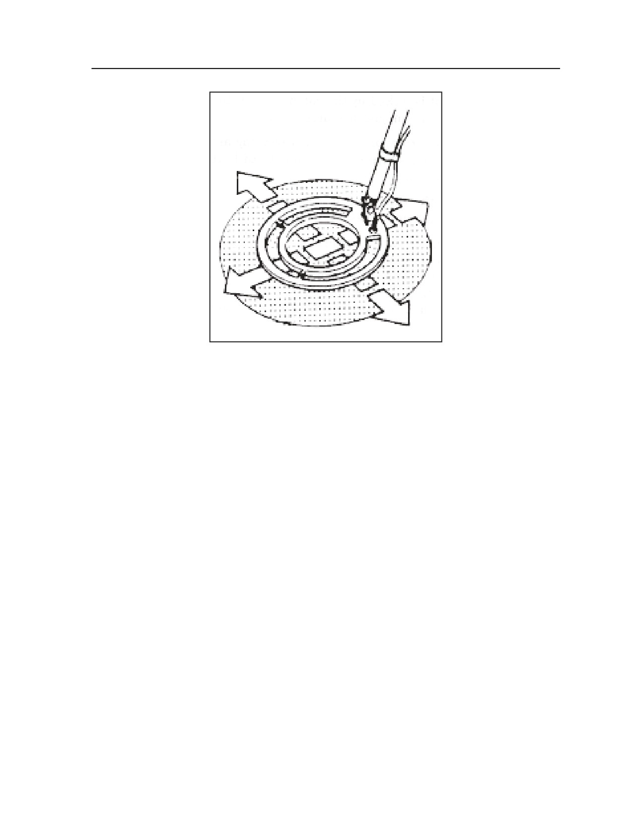
Demolitions and Obstacles
Figure H-27. X-Pattern sweeping movement
z
Keep mine detectors at least 2 meters apart during setting and adjustment phases to prevent
interference.
z
Change the batteries and readjust the unit if the indicator lamp flashes. The search sensitivity is
not affected when the lamp is flashing; if searching continues, a constant audible tone will sound
and the unit will be unusable until fresh batteries are installed.
z
Discontinue searching and readjust the unit's sensitivity if the check tone disappears or its
frequency decreases.
z
Ensure that only the inner part of the telescopic pole is used when the equipment is operated by
a Soldier in the prone position.
z
Turn the unit off after completing the search operations.
BREACHING AND CLEARING OPERATIONS
H-80. Table H-12 illustrates the characteristics and capabilities of explosive and manual breaching
methods. Table H-13 summarizes the characteristics of several types of obstacle breaching equipment.
Although the reconnaissance platoon does not have direct access to such assets, the platoon can take
advantage of these capabilities by calling on other elements for assistance in breaching operations.
3 August 2009
FM 3-20.98
H-45
Appendix H
Table H-12. Breaching assets and methods
EXPLOSIVE BREACHING ASSETS/METHODS
NOMENCLATURE
TYPE
MINES
WEIGHT
LANE CLEARED
ASSEMBLY TIME
EMPLOYMENT
CLEARED
(pounds)
in meters (feet)
TIME in minutes
(speed)
Width
M58A3
Trailer-
AT/AP
3,100
8 (26)
100 (328)
Crane and crew -
4 (25 mph)
(MICLIC)
mounted
35 minutes
M1A1
Portable
AP
130 per
0.6 (2)
15 (50)
1 squad -
5
(Bangalore torpedo)
kit
5 minutes
Antipersonnel
Portable
AP
115
0.6 (2)
45 (140)
2 Soldiers -
2
obstacle breaching
(in 2
2 minutes
system (APOBS)
manpack
units)
MANUAL BREACHING ASSETS/METHODS
BREACHING PROCEDURE
LANE CLEARED
MAN-HOURS REQUIRED
Width (type of lane)
(per 100 meters of lane)
Location by probing
1 meter (footpath)
16 to 22
Removal by rope or explosives
1 meter (footpath)
38 to 44
Location by detector, assisted by
8 meters (one-way vehicle lane)
27 to 33
probing
Removal by rope or explosives
8 meters (one-way vehicle lane)
220 to 247
Table H-13. Nonexplosive obstacle breaching equipment
NOMENCLATURE
MILITARY
HEIGHT
WIDTH
SPEED
ARMAMENT
MOBILITY EMPLOYMENT
LOAD
in meters
in meters
in kmph
CLASS
(feet)
(feet)
(mph)
M9
18
2.3
3.2
48
None
Fill craters and ditches
armored combat
(7.5)
(10.5)
(30+)
Remove road blocks, trees,
earthmover (ACE)
and rubble
Prepare river and ford
access
Prepare and maintain routes
D7F
28
2.4
3.48
10
None
Cut tactical routes
dozer
(7.9)
(11.4)
(6)
Fill craters and ditches
Remove rubble and trees
Loader (2½-ton)
20
3.7
2.6
NA
None
Fill craters and ditches
(12)
(8.5)
Remove wire obstacles
AVLB
57 (with
5
4
48
None
Bridge gaps of 18 meters or
bridge)
(16.4)
(13.1)
(30)
less
37
Bridge gaps of 15 meters or
(without
less for Load Class 70
bridge)
Note. Another nonexplosive breaching asset is the M1-series tank equipped with either the
mine-clearing blade or mine-clearing roller. Use of the tank affords a combination of breaching
capability, firepower, and mobility. The primary disadvantage is the vehicle’s weight. The blade
adds 3.5 tons and the roller 10 tons to the tank’s base weight of more than 60 tons. An M1
equipped with the roller exceeds the weight capacity of the AVLB.
H-46
FM 3-20.98
3 August 2009

Demolitions and Obstacles
OBSTACLE-CROSSING CAPABILITIES
H-81. Table H-14 summarizes the obstacle-crossing capabilities of selected vehicles and equipment of the
U.S. Army and allied nations.
Table H-14. Vehicle/equipment obstacle-crossing capabilities
COUNTRY/
VEHICLE
U.S. / M113
13
No
2.13
2.68
1.60
0.29
0.64
30
60
1.78
limit
(7.0)
(8.8)
(5.2)
(11)
(25)
(5.8)
U.S./ M2 and
24
No
2.92
3.04
2.54
0.45
0.91
40
60
1.87
M3
limit
(9.6)
(10.0
(8.3)
(18)
(36)
(6.1)
)
U.S. / M60
54
1.22
3.26
3.63
2.66
0.41
0.91
30
60
2.21
(4.0)
(10.7)
(12.0
(8.7)
(16)
(36)
(7.3)
)
U.S. / M48A5
1.22
3.12
3.63
2.59
0.41
0.91
30
60
2.21
(4.0)
(10.2)
(12.0
(8.5)
(16)
(36)
(7.3)
)
U.S. / M1 series
70
1.22
2.89
3.60
2.74
0.48
1.24
40
60
2.14
(M1A2)
(4.0)
(9.5)
(11.8
(9.0)
(19)
(49)
(7.0)
)
Germany /
46
2.25
2.93
3.71
3.00
0.48
1.15
30
60
2.15
Leopard 2
(7.4)
(9.6)
(12.2
(10.0)
(19)
(45)
(7.1)
)
UK / Centurian
60
1.20
2.96
3.40
3.35
0.51
0.90
30
60
2.19
(3.9)
(9.7)
(11.2
(11.0)
(20)
(35)
(7.2)
)
UK / Chieftain
45
1.07
2.90
3.66
3.15
0.51
0.91
30
60
2.44
(3.5)
(9.5)
(12.0
(10.3)
(20)
(36)
(8.0)
)
France / AMX30
38
2.00
2.86
3.10
2.90
0.45
0.93
30
60
1.96
(6.6)
(9.4)
(10.2
(9.5)
(18)
(37)
(6.4)
)
3 August 2009
FM 3-20.98
H-47
Appendix H
SECTION VI - FIELD-EXPEDIENT MINES AND DEMOLITIONS
H-82. This discussion describes a variety of field-expedient methods for constructing mines and
demolitions. The information in this discussion is for reference only. See FM 3-34.214 for detailed
explanations on constructing and employing field-expedient mines and demolitions.
WARNING
Employment of expedient and improvised mines and demolitions
must ALWAYS be in accordance with the applicable ROE, the
provisions of the Geneva Conventions, and the Law of Land
Warfare (see FM 27-10).
DANGER
The field-expedient devices and techniques described in this
discussion are intended for use only by personnel who are
experienced in mine and demolition employment and safety.
Other units/personnel should NEVER use expedient mines and
demolitions in place of standard devices and methods.
EXPEDIENT MINES
H-83. When constructing and employing improvised mines, the reconnaissance platoon must consider
safety, neutralization, and disarming requirements. Authorization of employment depends on the minefield
in which the mine is to be used. Figures H-28 through H-35 provide design and function guidance for
expedient mines. Actual construction will depend on several factors, including the availability of materials.
H-48
FM 3-20.98
3 August 2009
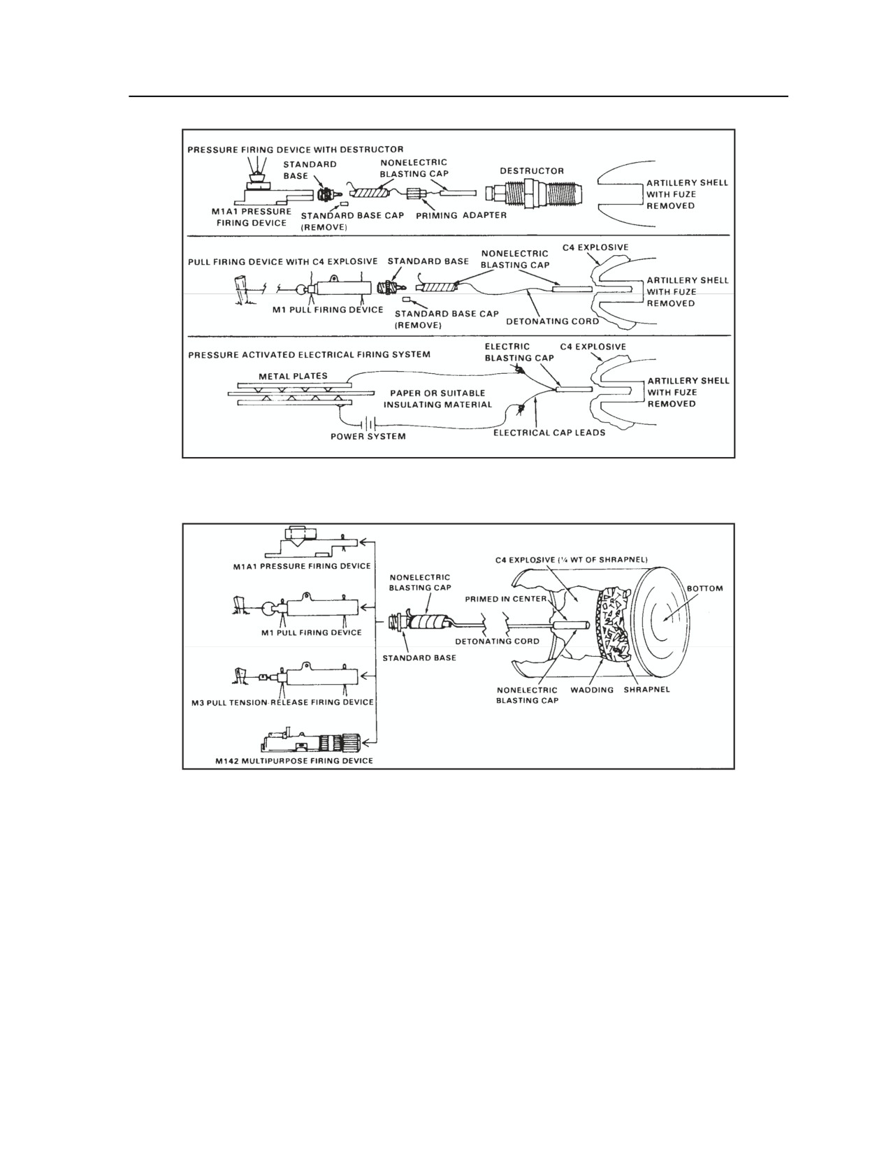
Demolitions and Obstacles
Figure H-28. Antitank mine using high-explosive artillery shell
(with three different firing systems)
Figure H-29. Grapeshot antipersonnel mine
3 August 2009
FM 3-20.98
H-49
Appendix H
Figure H-30. Plate charge expedient mine
Figure H-31. Improvised claymore mine
H-50
FM 3-20.98
3 August 2009
Demolitions and Obstacles
Figure H-32. Fragmentation grenade mine
(with 5-second delay)
Figure H-33. Barbed wire expedient mine
3 August 2009
FM 3-20.98
H-51
Appendix H
Figure H-34. Improvised flame mines
H-52
FM 3-20.98
3 August 2009
Demolitions and Obstacles
Figure H-35. Expedient firing devices
EXPEDIENT DEMOLITIONS
CRATERING CHARGE
H-84. To make a cratering charge, use a mixture of dry fertilizer (at least one-third nitrogen; refer to the
package contents list) and liquid (diesel fuel, motor oil, or gasoline) at a ratio of 25 pounds of fertilizer to a
quart of liquid. Mix the fertilizer and liquid and allow the mixture to soak for an hour. Place half of the
charge in a hole; add 1 pound of primed explosive, and then pour in the other half of the charge.
SHAPED CHARGE
H-85. Figure H-36 illustrates how to construct an expedient shaped charge.
3 August 2009
FM 3-20.98
H-53
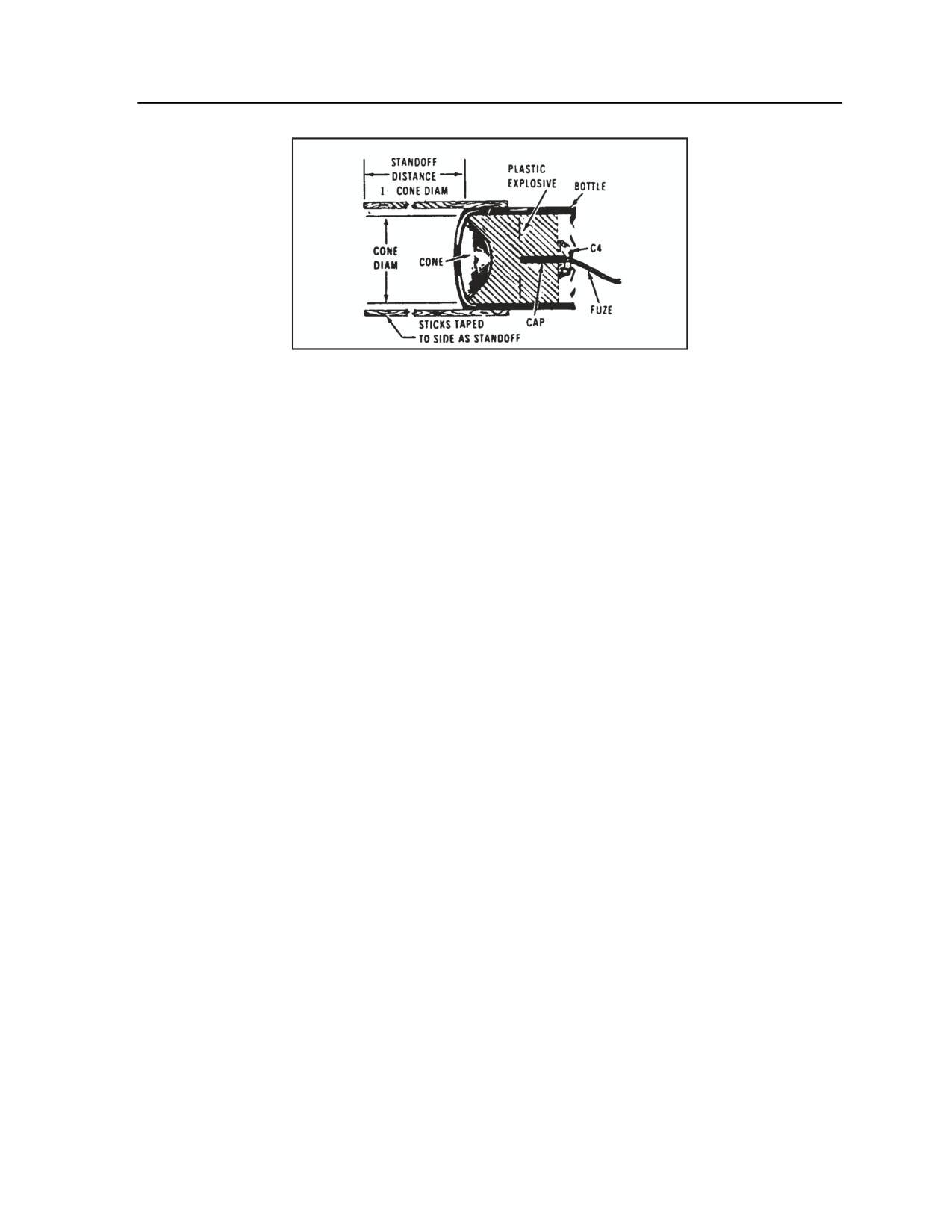
Appendix H
Figure H-36. Improvised shaped charge
SATCHEL CHARGE
H-86. Melt ordinary paraffin (wax) and stir in ammonium nitrate (fertilizer) pellets. Make sure the paraffin
is hot while mixing. Before the mixture hardens, add a ½-pound block of TNT, or its equivalent, as a
primer. Pour the mixture into a container. Shrapnel material can be added to the mixture if desired, or it can
be attached on the outside of the container to give a shrapnel effect.
IMPROVISED BANGALORE TORPEDO
H-87. The principal use of an improvised bangalore torpedo is to clear paths through barbed-wire
entanglements using one of the following methods:
z
Use any length of pipe with an approximate inside diameter of 2 inches and a wall thickness of
at least .025 inch (24 gauge). Pack the pipe with 2 pounds of explosive per foot of length. Close
one end of the pipe with a threaded cap, wooden plug, or damp earth.
z
Use any length of U-shaped picket. Pack the inside section of the picket with 2 pounds of
explosives per foot of length. Place the steel section of the U-shaped picket upward.
z
Use any length of board. Attach 4 pounds of explosive per foot of length. Place the explosives to
the top side of the board.
DETONATING CORD WICK
H-88. Use a detonating cord wick to widen the boreholes; one strand will generally widen a hole by 1 inch.
Tape the desired number of strands together, and prime one stick of dynamite with one of the strands. (The
dynamite is used to clean the hole.) Place the wick and the dynamite in a hole. The wick must extend from
the bottom of the hole to the surface. Prime the wick and detonate the dynamite. Make sure the hole is
“cold” before putting in any other explosives.
EXPEDIENT TIME FUZE
H-89. Soak a length of clean string (1/8 inch in diameter) in gasoline. Hang it to dry; then store it in a
tightly sealed container. Handle expedient fuzes as little as possible, and test them extensively before use.
MISCELLANEOUS IMPROVISED DEMOLITIONS
THERMITE
H-90. Using any size can, tie or tape sticks to the sides, and cut a small hole in the bottom. Cover the
bottom with paper. Place a round stick wrapped in paper in the middle of the can. Fill the bottom of the can
with ¼ inch of magnesium. Over this, place a mixture of three parts ferric oxide and two parts aluminum
H-54
FM 3-20.98
3 August 2009
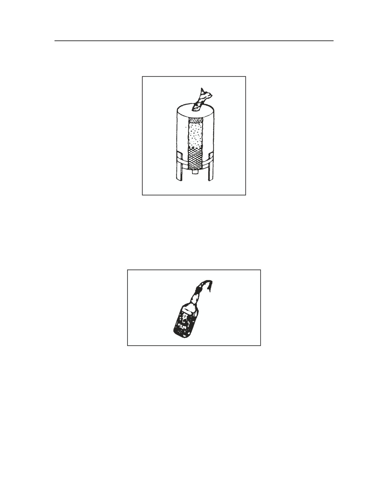
Demolitions and Obstacles
powder. Remove the stick, and fill the hole with a mixture of three parts potassium chlorate and one part
sugar. On top of this, place a paper bag containing the chlorate-sugar mixture. Place a fuze in the top, and
tamp with dirt or clay. Refer to Figure H-37.
Figure H-37. Thermite demolition
MOLOTOV COCKTAIL
H-91. Fill a bottle with napalm, jelly gas, or a 2-to-1 mixture of gas and oil. Insert a rag wick dipped in
wax. Light the wick before throwing the bottle.
(NOTE: Cotton rags burn slower than some other
materials, such as silk. Use a rag wick that will burn long enough so the Molotov cocktail reaches the
target before exploding.) Refer to Figure H-38.
Figure H-38. Molotov cocktail
SATCHEL CHARGE
H-92. Fill a #10 can with a mixture of ammonium nitrate and melted wax; stir vigorously to ensure a
complete mix. Add a small amount of C4 or TNT, and prime the charge with a time-fuze cord before the
mixture hardens. A rope handle creates a convenient improvised satchel charge.
IMPROVISED BLACK POWDER DEMOLITIONS
H-93. Table H-15 lists materials required for improvised black powder demolitions.
3 August 2009
FM 3-20.98
H-55
Appendix H
Table H-15. Materials in black powder demolitions
MATERIALS REQUIRED
PERCENT
PARTS
(by weight)
(by volume)
Potassium nitrate
74
28
Powdered charcoal
16
3
Sulfur
10
2
H-94. Dissolve the potassium nitrate using a ratio (by weight) of three parts water to one part nitrate. In a
second container, dry-mix the powdered charcoal and sulfur by stirring with a wooden stick or swirling or
shaking them in a tightly closed container. Add a few drops of the potassium nitrate solution to the dry
mixture, and blend to obtain a thoroughly wet paste. Then add the rest of the solution and stir. Pour the
mixture into a shallow dish or pan and allow it to stand until it has a paste-like consistency. Mix the paste
thoroughly with a wooden stick to assure uniformity, and set it aside for further drying. When the mixture
is nearly dried, granulate it by forcing it through a piece of wire screen. Spread the granules thinly, and
allow them to dry.
IMPROVISED FUZES
H-95. The following are three methods for making improvised string fuzes:
z
Put a string in a mixture of ¾ cup water and 1 teaspoon potassium chlorate. Boil for 30 minutes.
z
Soak a string in gasoline, and allow it to dry. This fuse will burn slowly.
z
Soak a string in a mixture of ¾ cup cold water and 2 teaspoons potassium nitrate.
IMPROVISED GRENADES
H-96. Use the following steps to make two types of improvised grenades:
z
Combine 7.8 parts potassium nitrate or sodium nitrate, 1.6 parts charcoal, and 1 part sulfur. No
detonator is required, just a fuse.
z
Combine 3 parts sodium chlorate and 3 parts sugar. Load the mixture into a lead pipe. No
detonator is required, just a fuse.
IMPROVISED DELAY MECHANISMS
H-97. Figure H-39 shows three types of delay mechanisms that can be used with improvised demolitions.
H-56
FM 3-20.98
3 August 2009
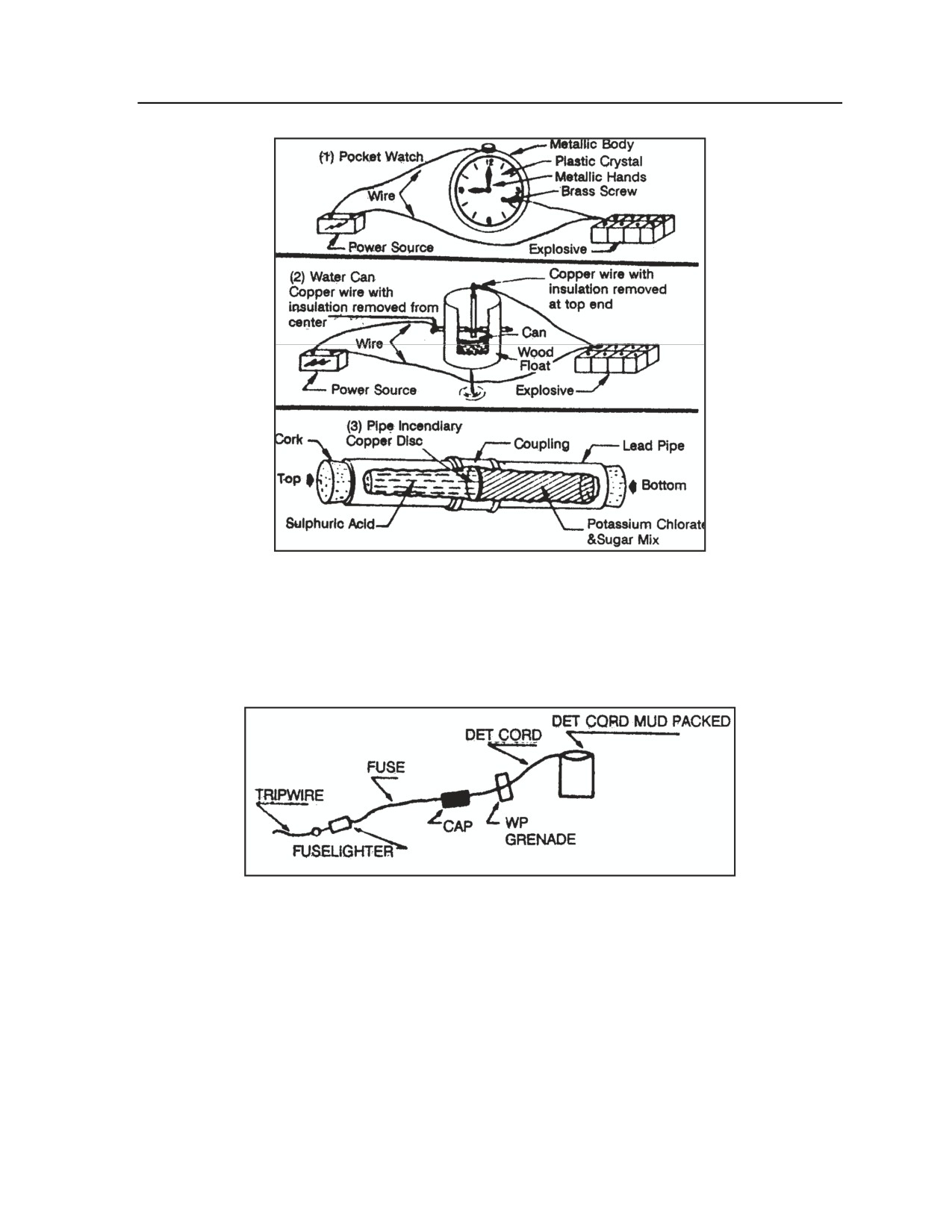
Demolitions and Obstacles
Figure H-39. Types of delay mechanisms
FLAME ILLUMINATOR
H-98. Fill a container to 3 inches from the top with thickened fuel, and seal the container tightly. Put three
wraps of detonating cord on the top inside rim, and pack with dirt or mud. Wrap a grenade with detonating
cord. Place the grenade next to the container, and tie it to the main detonating cord line. See Figure H-40.
Figure H-40. Flame illuminator
HUSCH FLARE
H-99. To construct a Husch flare, which burns for 90 minutes and lights a diameter of 50 meters, remove
the crossbars from a metal 60-mm mortar can. Punch three 3/8-inch holes in each side of the can halfway
between the top and bottom. Punch a hole no bigger than 1/8 inch in the bottom of a metal 81-mm mortar
shell container. Temporarily fill the holes; then fill the 81-mm container three-fourths full with thickened
fuel. Apply heavy grease to the cap, and tighten it. Place the 81-mm container cap-down in the 60-mm
container, and use stones or other materials to wedge it tightly. Then fill the 60-mm mortar can up to the
holes with thickened fuel. Remove the plug from the hole in the bottom of the 81-mm shell container. Tie
an illumination hand grenade between the 81-mm shell containers just above the level of the 60-mm mortar
can. Run a trip wire from the grenade pin.
3 August 2009
FM 3-20.98
H-57
Appendix H
DRIED SEED TIMER
H-100. The reconnaissance/scout platoons can use the properties of dried seeds, which expand when they
are soaked, to create a time delay device for electrical firing circuits. Required materials are the following:
z
Dried peas or beans or other dehydrated seeds.
z
Wide-mouthed glass jar with nonmetal cap.
z
Two screws or bolts.
z
Thin metal plate.
z
Hand drill.
z
Screwdriver.
H-101. Use the following steps to construct the dried seed timer:
z
Step 1. Determine the rate of rise of the dried seeds selected; this is necessary to determine the
amount of seeds needed to provide the required delay time. Use these steps:
Place a sample of dried seeds in the jar that will be used as the timer. Cover the seeds with
water.
Measure the time it takes for the seeds to rise a given height. Most dried seeds increase in
volume by 50 percent in 1 to 2 hours.
z
Step 2. Cut a disk from a thin metal plate. The disk should fit loosely inside the jar. Refer to
Figure H-41.
Note. If the metal is painted, rusty, or otherwise coated, it must be scraped or sanded to create a
clean metal surface.
z
Step 3. Drill two holes in the cap of the jar about 2 inches apart. The diameter of the holes
should be such that screws or bolts will thread tightly into them. If the jar has a metal cap or no
cap, a piece of wood or plastic (NOT METAL) can be used as a cover. See Figure H-42.
z
Step 4. Turn the two screws or bolts through the holes in the cap. The bolts should extend about
1 inch (2½ cm) into the jar. See Figure H-43 (top).
CAUTION
Both bolts must extend the same distance below the container cover.
z
Step 5. Pour the required quantity of dried seeds into the container. The level will depend on the
previously measured rise time and the desired delay. Refer to Figure H-42 (middle).
z
Step 6. Place the metal disk in the jar on top of the seeds. Refer to Figure G-42 (middle).
H-102. Use the following steps to activate and employ the dried seed timer:
z
Step 1. Add just enough water to completely cover the seeds, and place the cap on the jar. Refer
to Figure H-42 (bottom).
z
Step 2. Attach the connecting wires from the firing circuit to the two screws on the cap. Refer
to Figure H-42 (bottom).
z
Step 3. Expansion of the seeds will raise the metal disk until it makes contact with the screws
and closes the circuit, triggering the explosive. Figure H-43 illustrates the complete explosive
device with a dried seed timer.
H-58
FM 3-20.98
3 August 2009
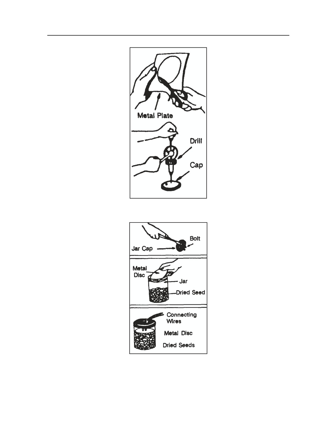
Demolitions and Obstacles
Figure H-41. Cutting and drilling metal plate
Figure H-42. Inserting bolts, seeds, and metal disc;
completed timer with water added and wires connected
3 August 2009
FM 3-20.98
H-59
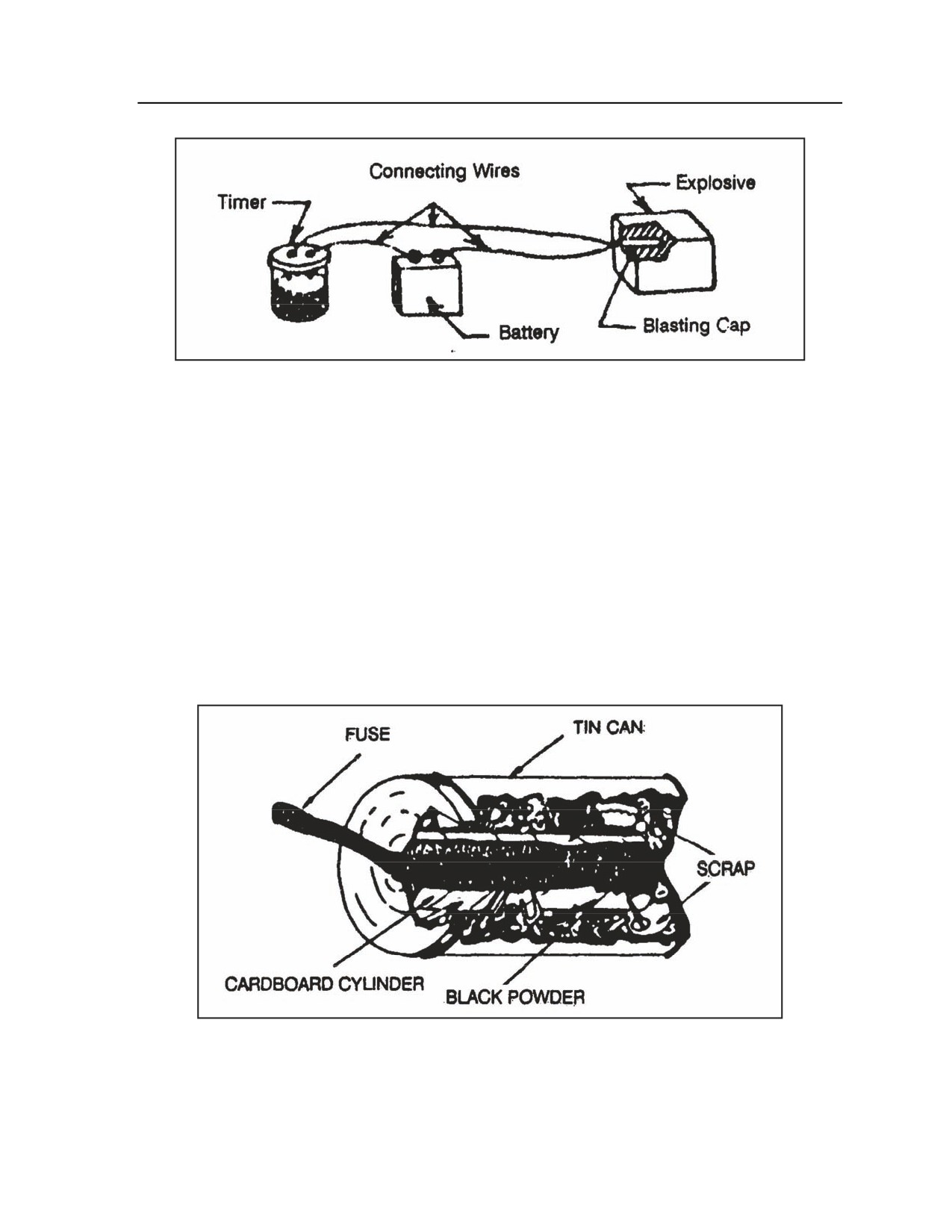
Appendix H
Figure H-43. Explosive device with dried seed timer attached
TIN CAN GRENADE
H-103. Construction of a tin can grenade requires the following materials:
z
Tin can, jar, or similar container.
z
Bolts, nuts, metal scrap, and/or other solid objects.
z
Commercial or improvised black powder.
z
Commercial or improvised fuse cord.
z
Cardboard or heavy paper and tape.
H-104. Construct a cardboard or heavy-paper cylinder using tape that is approximately one-half the
diameter of the tin can or other container. Insert the fuze into one end of the paper cylinder, pack the
cylinder tightly with black powder, and tape the ends closed. Insert the cylinder into the can as shown in
Figure H-44, and surround it with such items as bolts, nuts, metal scrap, or stones. Close the can with a lid
that has a hole in the center through which to pass the fuze. If the container has no lid, it may be closed
with a piece of wood, metal, or cardboard of the required size taped in place.
Figure H-44. Tin can grenade
H-60
FM 3-20.98
3 August 2009
Demolitions and Obstacles
FIELD-EXPEDIENT DELAYS
H-105. The reconnaissance/scout platoons can take advantage of a variety of materials for use as
expedient delay mechanisms in the employment of demolitions. Examples include the following:
z
Cigarette (in matchbook or box).
z
Candle (surrounded by flammable material).
z
Spark (from short-circuited electrical wires).
z
Sulfuric acid (sugar chlorate mixture).
z
Glycerin (sugar permangate mixture).
z
Nitrate acid (sugar chlorate mixture).
z
Water delay (see Figure H-41).
z
Watch delay (see Figure H-41).
COMMON CHEMICALS IN FIELD-EXPEDIENT DEMOLITIONS
H-106. Table H-16 lists a number of chemicals that are commonly used in expedient demolitions. The
table includes sources for these substances, including local sites that may provide the reconnaissance
platoon with access to necessary chemicals.
Table H-16. Common chemicals in expedient demolitions
CHEMICAL
SYMBOL
POSSIBLE SOURCES
Potassium permanganate
KMNO4
Drug store, hospital, gym
Potassium chlorate
KCLO3
Drug store, hospital, gym
Potassium nitrate
KNO3
Fertilizer or explosives factory
Sodium nitrate
NgNO3
Fertilizer or glass factory
Ammonium nitrate
(NH4)NO3
Fertilizer or explosives factory
Ferric oxide
Fe2O3
Hardware or paint store
Powdered aluminum
Al
Paint, electric, or auto parts store
Magnesium
Mg
Auto, machine, or chemical
factory
Glycerin
C3H5(OH)3
Drug store, soap/candle factory
Sulfuric acid
H2SO4
Garage, machine shop, hospital
Sodium chlorate
NgClO3
Match or explosives factory
Sulfur
S
Drug store, match factory
3 August 2009
FM 3-20.98
H-61
This page intentionally left blank.
Glossary
ACRONYMS AND ABBREVIATIONS
1SG
first sergeant
A/L
administrative/logistics
AA
avenue of approach
AAR
after action review
AB
abates (obstacle graphics)
ABCS
Army Battle Command System
ACA
airspace coordination area
ACR
armored cavalry regiment
ADA
air defense artillery
AFATDS
Advanced Field Artillery Tactical Data System
AHS
Army health system
ALO
air liaison officer
ALSA
Air Land Sea Application (Center)
AM
amplitude modulation
AMC
air mission commander
AMD
air and missile defense
AO
area of operations
AP
antipersonnel
APC
armored personnel carrier
AR
Army regulation
ASAS
All Source Analysis System
ASCOPE
areas, structures, capabilities, organizations, people, events
AT
antitank
ATGM
antitank guided missile
AVLB
armored vehicle launched bridge
BCIS
battlefield combat identification system
BCS3
battle command sustainment and support system
BCT
brigade combat team
BDA
battle damage assessment
BFSB
battlefield surveillance brigade
BFT
Blue Force Tracker
BHL
battle handover line
BHO
battle handover
BMNT
begin morning nautical twilight
BP
battle position
BRIDGEREP
bridge report
3 August 2009
FM 3-20.98
Glossary-1
Glossary
C2
command and control
CA
civil affairs
CAB
combined arms battalion
CALL
Center for Army Lessons Learned
CAO
civil affairs operations
CAS
close air support
CASEVAC
casualty evacuation
CAT
civil affairs team
CBRN
chemical, biological, radiological, and nuclear
CBU
cluster bomb unit
CCA
close combat attack
CCIR
commander’s critical information requirement
CCP
casualty collection point
CEXC
combined explosives exploitation cell
CFF
call for fire
CFL
coordinated fire line
CFSO
counterintelligence force protection source operation
CFV
cavalry fighting vehicle
CFZ
critical friendly zone
CI
counterintelligence
CIA
Central Intelligence Agency
CID
combat identification
CIDDS
combat identification system dismounted Soldier
CIP
combat identification panel
CMO
civil-military operations
COA
course of action
COIN
counterinsurgency
COLT
combat lasing observation team
COMSEC
communications security
COP
common operational picture
COSC
combat and operational stress control
CP
command post
CRM
composite risk management
CROSSREP
crossing site report
CW
concertina wire (obstacle graphics)
DA
Department of the Army
DA APM
Department of the Army pamphlet
DCIMS
dismounted Solider combat identification marking system
DDL
digital data link
DIDEA
detect, identify, decide, engage, assess
Glossary-2
FM 3-20.98
3 August 2009
Glossary
DOCEX
document exploitation
DOD
Department of Defense
DP
decision point
DPICM
dual-purpose improvised conventional munitions
DS
direct support
DTG
date-time group
DZ
drop zone
EA
engagement area
EEFI
essential elements of friendly information
EENT
end evening nautical twilight
EFP
explosively formed penetrator
EO
electro-optical
EOD
explosive ordnance disposal
EOF
escalation of force
EPLRS
enhanced position location and reporting system
EPW
enemy prisoner of war
ESTAT
equipment status report
EW
electronic warfare
FA
field artillery
FBCB2
Force XXI Battle Command, Brigade and Below
FBI
Federal Bureau of Investigation
FC
fires cell
FDC
fire direction center
FEBA
forward edge of the battle area
FFA
free fire area
FFIR
friendly force information requirement
FIPR
flash immediate priority routine
FIST
fire support team
FLIR
forward-looking infrared
FM
field manual; frequency modulation
FMI
field manual, interim
FO
forward observer
FOB
forward operating base
FPF
final protective fire
FRAGO
fragmentary order
FRIES
fast rope insertion/extraction system
FSCL
fire support coordination line
FSCM
fire support coordination measure
FSO
fire support officer
GCS
ground control station
3 August 2009
FM 3-20.98
Glossary-3
Glossary
GIRS
grid index reference system
GMLRS
guided Multiple Launch Rocket System
GPS
global positioning system
GS
general support
HBCT
heavy brigade combat team
HCT
human intelligence collection team
HE
high explosive
HELOCAST
helicopter cast and recovery
HHC
headquarters and headquarters company
HIIDE
handheld interagency identity detection equipment
HIMARS
high mobility artillery rocket system
HMMWV
high mobility multipurpose wheeled vehicle
HN
host nation
HPT
high-payoff target
HQ
headquarters
HUMINT
human intelligence
HVT
high-value target
IAW
in accordance with
IBCT
infantry brigade combat team
ID
identification
IED
improvised explosive device
IFF
identification, friend or foe
IFV
infantry fighting vehicle
IMINT
imagery intelligence
IO
information operations
IPB
intelligence preparation of the battlefield
IR
information requirement
ISR
intelligence, surveillance, and reconnaissance
IV
intervisibility
JCIMS
joint combat identification marking system
JFO
joint fires observer
JP
joint publication
JSTARS
Joint Surveillance Target Attack Radar System
JTAC
joint terminal attack controller
JTF
joint task force
JVMF
joint variable message format
KIA
killed in action
km
kilometer
kmph
kilometers per hour
LC
line of contact
Glossary-4
FM 3-20.98
3 August 2009
Glossary
LD
line of departure
LD/LC
line of departure is line of contact
LNO
liaison officer
LOA
limit of advance
LOGPAC
logistics package
LOS
line of sight
LRAS3
long-range advanced scout surveillance system
LTD
laser target designator
LZ
landing zone
m
meter
MASINT
measurement and signature intelligence
MCO
major combat operation
MCOO
modified combined obstacle overlay
MDI
modern demolition initiator
MDMP
military decision-making process
MEDEVAC
medical evacuation
METT-TC
mission, enemy, terrain and weather, troops and support available, time
available, civil considerations
MF
minefield (obstacle graphics)
MGS
mobile gun system
MI
military intelligence
MICO
military intelligence company
MLC
military load classification
MLRS
multiple launch rocket system
MOPMS
modular pack mine system
MOPP
mission-oriented protective posture
MOS
military occupational specialty
MP
military police
mph
miles per hour
MRE
meals, ready to eat
MSR
main supply route
MTF
medical treatment facility
MTOE
modified table of organization and equipment
MWD
military working dog
NAI
named area of interest
NATO
North Atlantic Treaty Organization
NBC
nuclear, biological, and chemical (used in report titles only; replaced by
abbreviation CBRN in normal use)
NCO
noncommissioned officer
NEO
noncombatant evacuation operation
NFA
no-fire area
3 August 2009
FM 3-20.98
Glossary-5
Glossary
NGF
naval gunfire
NGO
nongovernmental organization
NLT
no later than
NOD
night observation device
NVG
night vision goggles
OAKOC
observation and fields of fire; avenues of approach; key terrain;
obstacles; and cover and concealment
OBSTINTEL
obstacle intelligence
OE
operational environment
OEF
Operation Enduring Freedom
OIC
officer in charge
OIF
Operation Iraqi Freedom
OP
observation post
OPCON
operational control
OPLAN
operation plan
OPORD
operation order
OPSEC
operations security
ORP
objective rally point
OT
observer-target
PC
pint of curvature
PCC
precombat check
PCI
precombat inspection
PGM
precision-guided munitions
PIR
priority intelligence requirement
PL
phase line
PMCS
preventive maintenance checks and services
PMESII-PT
political, military, economic, social, information, infrastructure, physical
environment, time
POL
petroleum, oil, and lubricants
POSNAV
position navigation
PSG
platoon sergeant
PSYOP
psychological operations
PT
point of tangency
PVNTMED
preventive medicine
PZ
pickup zone
QRF
quick reaction force
R&S
reconnaissance and surveillance
RALS
right add, left subtract
RAP
rocket-assisted projectile
RC
road crater (obstacle graphics)
RE
relative effectiveness
Glossary-6
FM 3-20.98
3 August 2009
Glossary
REDCON
readiness condition
RFA
restrictive fire area
RFL
restrictive fire line
RHO
reconnaissance handover
RHOCP
reconnaissance handover coordination point
RHOL
reconnaissance handover line
ROE
rules of engagement
ROI
rules of interaction
ROUTEREP
route report
RP
release point
RPG
rocket-propelled grenade
RTO
radio-telephone operator
RTP
radiotelephone procedures
RV
reconnaissance vehicle
RVT
remote video terminal
S-2
intelligence staff officer
S-3
operations staff officer
SA
situational awareness
SALT
size, activity, location, time
SALUTE
size, activity, location, unit, time, equipment
SBCT
Stryker brigade combat team
SBF
support by fire
SE
site exploitation
SEAD
suppression of enemy air defenses
SENSERER
sensitive item report
SERE
survival, escape resistance, evasion
SIGINT
signals intelligence
SINCGARS
single-channel ground and airborne radio system
SIR
specific information requirement
SITREP
situation report
SITTEMP
situation template
SOF
special operations forces
SOFA
status-of-forces agreement
SOI
signal operating instructions
SOP
standing operating procedure
SOSRA
suppression, obscuration, security, reduction, assault
SP
start point
SPIES
special mission infiltration/exfiltration system
SPOTREP
spot report
SSC
small-scale contingency
3 August 2009
FM 3-20.98
Glossary-7
Glossary
SSG
staff sergeant
STANREP
stand-to report
SU
situational understanding
SWEAT-MSO
sewage, water, electricity, academics, trash, medical, safety, and other
considerations
SWT
scout weapons team
TAC CP
tactical command post
TACSAT
tactical satellite
TAI
target area of interest
TCP
traffic control point
TD
tank ditch (obstacle graphics)
TI
target identification
TIRS
terrain index reference system
TM
technical manual
TOC
tactical operations center
TOR
terms of reference
TOW
tube-launched, optically tracked, wire-guided
TPT
tactical psychological operations team
TQ
tactical questioning
TRP
target reference point
TTP
tactics, techniques, and procedures
TV
television
U.S.
United States
UAS
unmanned aircraft system
UGV
unmanned ground vehicle
UHF
ultrahigh frequency
UN
United Nations
UTM
universal transverse Mercator
VBIED
vehicle-borne improvised explosive device
VHF
very high frequency
WARNO
warning order
WIA
wounded in action
WIT
weapons inspection team
WMD
weapons of mass destruction
WP
white phosphorus
XO
executive officer
Glossary-8
FM 3-20.98
3 August 2009
References
SOURCES USED
These are the sources quoted or paraphrased in this publication.
JOINT PUBLICATIONS
JP 1-02, Department of Defense Dictionary of Military and Associated Terms, 12 April 2001
JP 3-09, Joint Fire Support, 13 November 2006.
JP 3-09.03, Close Air Support, 8 July 2009.
ARMY PUBLICATIONS
AR 1-100, Gifts and Donations, 15 November 1983.
AR 381-10, U.S. Army Intelligence Activities, 3 May 2007.
AR 381-172, Counterintelligence Force Protection Source Operations (CFSO) and Low Level Source
Operations (LLSO), 30 December 1994.
AR 385-63, Range Safety, 19 May 2003.
DA Pam 350-38, Standards in Training Commission, 13 May 2009.
DA Pam 750-8, The Army Maintenance Management System (TAMMS) Users Manual, 22 August 2005.
FM 1-0, Human Resources Support, 21 February 2007.
FM 1-02, Operational Terms and Graphics, 21 September 2004.
FM 2-0, Intelligence, 17 May 2004.
FM 2-22.3, Human Intelligence Collector Operations, 6 September 2006.
FM 3-0, Operations, 27 February 2008.
FM 3-04.111, Aviation Brigades, 7 December 2007.
FM 3-04.113, Utility and Cargo Helicopter Operations, 7 December 2007.
FM 3-04.126, Attack Reconnaissance Helicopter Operations, 16 February 2007.
FM 3-04.15, Multiservice Tactics, Techniques, and Procedures for the Tactical Employment of Unmanned
Aircraft Systems, 3 August 2006.
FM 3-05.301, Psychological Operations Tactics, Techniques, and Procedures, 30 August 2007.
FM 3-05.40, Civil Affairs Operations, 29 September 2006.
FM 3-05.210, Special Forces Air Operations, 27 February 2009.
FM 3-05.302, Tactical Psychological Operations Tactics, Techniques, and Procedures, 28 October 2005.
FM 3-06, Urban Operations, 26 October 2006.
FM 3-06.11, Combined Arms Operations in Urban Terrain, 28 February 2002.
FM 3-09.31, Tactics, Techniques, and Procedures for Fire Support for the Combined Arms Commander,
1 October 2002.
FM 3-09.32, (JFIRE) Multiservice Tactics, Techniques, and Procedures for the Joint Application of
Firepower, 20 December 2007.
FM 3-11.3, Multiservice Tactics, Techniques, and Procedures for Chemical, Biological, Radiological, and
Nuclear Contamination Avoidance, 2 February 2006.
FM 3-11.4, Multiservice Tactics, Techniques, and Procedures for Nuclear, Biological, and Chemical
(NBC) Protection, 2 June 2003.
FM 3-20.15, Tank Platoon, 22 February 2007.
3 August 2009
FM 3-20.98
References-1
References
FM 3-20.90, Tank and Cavalry Headquarters and Headquarters Company (HHC) and Headquarters and
Headquarters Troop (HHT), 25 August 2004.
FM 3-20.96, Calvary Squadron (RSTA), 20 September 2006.
FM 3-20.151, The Mobile Gun System Platoon, 22 November 2005.
FM 3-20.971, Reconnaissance Troop: Recce Troop and Brigade Reconnaissance Troop, 2 December
2002.
FM 3-21.10, The Infantry Rifle Company, 27 July 2006.
FM 3-21.38, Pathfinder Operations, 25 April 2006.
FM 3-21.71, Mechanized Infantry Platoon and Squad (Bradley), 20 August 2002.
FM 3-21.8, The Infantry Rifle Platoon and Squad, 28 March 2007.
FM 3-22.90, Mortars, 7 December 2007.
FM 3-24, Counterinsurgency, 15 December 2006.
FM 3-31, Joint Force Land Component Commander Handbook (JFLCC), 13 December 2001.
FM 3-34, Engineer Operations, 2 April 2009.
FM 3-34.170, Engineer Reconnaissance, 25 March 2008.
FM 3-34.210, Explosive Hazards Operations, 27 March 2007.
FM 3-34.214, Explosives and Demolitions, 11 July 2007.
FM 3-34.22 (FM 3-34.221), Engineer Operations Brigade Combat Team and Below, 11 February 2009.
FM 3-34.343, Military Nonstandard Fixed Bridging, 12 February 2002.
FM 3-90, Tactics, 4 July 2001.
FM 3-90.6, The Brigade Combat Team, 4 August 2006.
FM 3-90.15, Sensitive Site Operations, 25 April 2007.
FM 3-97.6, Mountain Operations, 28 November 2000.
FM 4-02.17, Preventive Medicine Services, 28 August 2000
FM 4-02.51, Combat and Operational Stress Control, 6 July 2006
FM 4-20.197, Multiservice Helicopter Sling Load: Basic Operations and Equipment, 20 July 2006.
FM 5-0, Army Planning and Orders Production, 20 January 2005.
FM 5-19, Composite Risk Management, 21 August 2006.
FM 5-34, Engineer Field Data, 19 July 2005.
FM 6-0, Mission Command: Command and Control of Army Forces, 11 August 2003.
FM 6-20-40, Tactics, Techniques, and Procedures for Fire Support for Brigade Operations (Heavy),
5 January 1990.
FM 6-22.5 (FM 22-51), Combat and Operational Stress Control Manual for Leaders and Soldiers,
18 March 2009.
FM 7-93, Long-Range Surveillance Unit Operations, 3 October 1995.
FM 17-95, Cavalry Operations, 24 December 1996.
FM 27-10, The Law of Land Warfare, 18 July 1956.
FM 34-5, Human Intelligence and Related Counterintelligence Operations, 29 July 1994.
FM 34-54, Technical Intelligence, 30 January 1998.
FM 34.60, Counterintelligence, 3 October 1995.
FMI 2-01.301 (FM 34-130), Specific Tactics, Techniques, and Procedures and Applications for
Intelligence Preparation of the Battlefield, 31 March 2009.
FMI 5-0.1, The Operations Process, 31 March 2006.
References-2
FM 3-20.98
3 August 2009
References
DOCUMENTS NEEDED
These documents must be available to the intended users of this publication. DA Forms are available on the
DA Form 1156, Casualty Feeder Card.
DA Form 1355, Minefield Record.
DA Form 1355-1, Hasty Protective Row Minefield Record.
DA Form 1594, Daily Staff Journal or Duty Officer’s Log.
DA Form 2028, Recommended Changes to Publications and Blank Forms.
DA Form 2203, Demolition Reconnaissance Record.
DA Form 2408-18, Equipment Inspection List.
DA Form 5988-E, Equipment Inspection Maintenance Worksheet (EGA).
DA Form 7566, Composite Risk Management Worksheet.
READINGS RECOMMENDED
These sources contain relevant supplemental information.
FM 1, The Army, 14 June 2005.
Center for Army Lessons Learned (CALL) Handbook 07-26, Tactical Site Exploitation and Cache Search
Operations, May 2007.
CALL Handbook 04-7, Interpreter Operations, Multiservice Reference Manual for Interpreter Operations,
February 2004, Air Land Sea Application Center, March 2004.
3 August 2009
FM 3-20.98
References-3
This page intentionally left blank.
Index
combat and operational stress
A
B
control (COSC), 6-68
actions on contact, 2-2, 2-13,
battle command, 2-17
combat engineers. see
2-15, 3-25, 4-40, 4-48, 5-23,
battle drills, 2-2, 2-15, 2-21, 3-
engineers, 6-40
5-53, 5-61, 5-88, 5-89, 5-90,
3, 5-23, 5-25, 5-26, 5-68, 5-
C-10, E-4, H-43
combat identification (CID), D-
89, E-4
1, D-4, D-13
after-action review (AAR), C-3,
battle handover (BHO), 2-31, 3-
D-5, E-6
combat medics, 6-65
11, 3-13, 5-26, 5-29, 5-39, 5-
air and missile defense (AMD),
45, 5-49, 5-50, 5-55
combat outpost, 4-39, 5-105
3-18, 5-48, 6-31, 6-53
battlefield surveillance brigade
combined arms battalion
active air defense
(BFSB), xviii, 1-1, 1-6
(CAB), 1-6
measures, 6-54
BFSB reconnaissance
CAB reconnaissance
air defense warnings, 6-56
platoon, 1-10
platoon, 1-19
passive air defense
command and control (C2), xxi,
measures, 6-53
C
1-3, 2-1, 2-18, 3-11, 3-12, 3-
ambush, 1-33, 3-62, 3-63, 4-
captured documents and
23, 3-57, 3-73, 4-19, 4-20, 4-
35, 4-36, 4-37, 4-41, 4-46, 5-
equipment, 6-70
40, 5-10, 5-12, 5-48, 5-51, 5-
3, 5-8, 5-57, 5-69, 5-86, 5-
casualty evacuation
54, 6-40, 6-56
95, 5-102, 5-105, 6-38, 6-48,
(CASEVAC), 2-2, 2-13, 3-22,
areas of influence, 2-23
C-3, C-6, H-37
3-24, 3-40, 3-48, 3-52, 3-57,
battle command, 2-17
area of influence, 2-23
4-21, 4-40, 4-57, 5-53, 5-88,
command relationships, 2-
6-28, 6-31, 6-39, 6-66, 6-67,
18
area of operations (AO), 1-1,
C-10, C-11
communications, 2-29
1-4, 1-26
FBCB2, 2-19
cavalry squadron (ACR), xx, 1-
area reconnaissance, 1-7, 3-56
fratricide prevention, 2-27
6, 3-21, 4-2
critical tasks, 3-56
in obstacle/minefield
techniques, 3-57
chemical, biological,
turnover, H-43
radiological, and nuclear
area security, 1-7, 4-3, 4-32
in urban operations, C-3
(CBRN), xx, 2-6, 2-17, 5-24,
operational considerations,
intelligence preparation of
5-43, 5-54, 5-65, 6-63, D-4,
4-33
the battlefield (IPB), 2-28
F-1
supporting tasks, 4-32
reports and reporting, 2-34,
contamination avoidance, F-
techniques, 4-34
A-12, A-13
1
situational awareness (SA),
armored cavalry regiment
crossing a contaminated
2-22
(ACR), xviii, 1-1, 1-6
area, F-4
troop-leading procedures, 2-
ACR scout platoon, 1-22
decontamination, F-5
1
Army aviation, xxi, 3-12, 3-17,
defense, F-3
with unmanned aircraft
6-23, 6-28, B-8, D-16
movement, F-4
systems (UAS), 6-46
assault/cargo helicopter
NBC reports, 2-19, 2-35, A-
communications, 1-6, 2-13, 2-
support, 6-28
31
16, 2-18, 2-23, 2-29
in urban operations, C-3
reconnaissance, 1-17, 3-17
chemical, biological,
medical evacuation
civil affairs (CA), 1-6, 3-40, 3-
radiological, and nuclear
(MEDEVAC), 6-38
72, 4-34, 5-9, 5-43, 6-43, 6-
(CBRN), F-4
organization, 6-28
52, B-7, B-9, C-10, C-11
commercial lines, 2-31
Army health system (AHS). see
civil support operations, 1-3
digital, 2-31
also medical support, 6-65
equipment maintenance, 6-
civil-military operations (CMO),
ASCOPE (analysis of civil
62
3-38, 3-41, 3-42, 6-52
considerations), 1-2, 2-9
FBCB2 components and
close air support (CAS), 4-1, 4-
capabilities, 2-19
assembly areas, 5-42
19, 4-21, 4-36, 4-41, 5-87, 5-
in assembly areas, 5-45
characteristics, 5-43
90, 6-2, 6-6, 6-23, 6-53, C-3,
departure, 5-45
in aviation operations, 6-29,
D-11
6-30, 6-33
occupation, 5-44
close combat attack (CCA), 4-
in linkup operations, 5-46
quartering party, 5-43
1, 4-19, 5-87, 5-90, 6-28, C-
in observation post (OP), 5-
security, 5-44
3, D-11, D-17
62, 5-67, 5-68, 5-71
3 August 2009
FM 3-20.98
Index-1
Index
in passage of lines, 5-51
cultural awareness, 1-2
sources of risk, E-7
in patrols, 5-95, 5-101
training, E-7
D
in reconnaissance
escalation of force (EOF), 3-8,
operations, 3-2, 3-10, 3-
danger areas, 2-10, 3-19, 3-23,
5-57, B-6, C-3, C-10, D-16
11, 3-12, 3-18, 3-19, 3-
3-27, 3-56, 3-72, 4-46, 5-3,
exfiltration, 3-35, 6-29, C-9
22, 3-24, 3-36, 3-43
5-6, 5-7, 5-73, 5-84, 5-85, 5-
in reports and reporting, A-
88, 5-89, 5-90
explosive ordnance disposal
11
in urban operations, C-7
(EOD), 3-61, B-1, B-4, B-6,
in security operations, 4-1,
tactical movement
B-8
4-5, 4-10, 4-12, 4-55
considerations, 5-95, 5-
explosively formed penetrators
in site exploitation (SE), B-2
98
(EFP), 4-47, B-5, B-8
in urban operations, 5-9, C-
defensive operations, 1-3, 3-
extraction, 3-22, 3-24, 3-36, 3-
2, C-3, C-8, C-9, C-10
36, D-12
37, 5-88, 6-30, C-9
means of communications,
demolitions, H-1
2-29
F
characteristics, H-2
messenger, 2-30
expedient demolitions, H-53
FBCB2, 1-11, 1-27, 1-33, 2-13,
nets (platoon/troop), 2-31
explosive charges, H-15
2-14, 2-17, 2-29, 2-31, 3-3,
platoon responsibilities, 2-
firing systems, H-3, H-7
5-2
33
mines and minefields, H-30
capabilities, 2-20
radio, 2-30
reconnaissance report, H-
components, 2-19
radio voice, 2-31
41
fratricide prevention, 4-49,
role in composite risk
safety, H-4
D-3, D-4
management (CRM), E-1
in actions on contact, 5-23
role in fratricide prevention,
direct fire planning, 4-48
in linkup operations, 5-45,
D-3, D-5
engagement area
5-47
role in reports and reporting,
development, 4-50
in observation post (OP), 5-
2-35
standing operating
67
role in target identification,
procedures (SOP), 4-49
in passage of lines, 5-52
D-17
dismounted operations, 1-8, 3-
in patrols and patrolling, 5-
sound, 2-30
18, 3-34, 5-6, 5-62, 5-78, 5-
79, 5-85
TACSAT, 2-31
89, C-10
in reconnaissance
techniques, 2-33
operations, 3-11, 3-12, 3-
visual, 2-30
E
13, 3-16, 3-19, 3-48, 3-63
wire, 2-30
enemy prisoners of war (EPW),
in security operations, 4-42,
composite risk management
2-13, 3-38, 3-39, 3-40, 3-41,
4-46, 4-49, 4-55
(CRM), 2-10, 2-13, 5-55, E-
3-42, 5-46, 5-47, 5-53, 5-81,
in unmanned aerial vehicle
1, H-4
5-86, 6-69, B-10, B-12, B-13,
(UAS) operations, 6-50
implementation, E-6
C-3
orders and graphics, 2-22
procedures (steps), E-1
engagement criteria, 2-5, 3-8,
orders and reports, A-12
types of risk (accident,
4-5
reports and reporting, 2-21,
threat), E-1
2-34, A-11, A-15, A-23
engagement/displacement
concept of operations, 2-5, 2-
role in battle command, 2-
criteria (security operations),
15, 2-18, 4-48, 5-26, 5-87, A-
19
4-5
3, A-17, C-5
situational awareness (SA),
engineers, 1-26, 2-7, 6-40
2-20, 2-23, D-15
convoy security, 4-3, 4-37
bridge classification, G-30
combat outposts, 4-39
field artillery (FA), 6-4
in assembly areas, 5-44
convoy escort procedures,
in combat outposts, 5-105
capabilities and limitations,
4-39
6-5
in cordon and search, 5-56
cordon and search, 4-33, 5-55,
in reconnaissance
fire support coordination
B-2, B-3, B-8, B-9, C-2
operations, 3-47, 3-61, 3-
measures (FSCM), 5-46, 5-
63, 3-64, 3-65, 3-66, 6-40
90, 6-19
counterinsurgency (COIN)
in security operations, 4-5,
operations, 1-6, 6-53
fire support team (FIST), 1-7,
4-7, 4-21, 4-34, 4-35, 4-
4-36, 4-55, 5-67, 6-6, 6-7, 6-
counterintelligence (CI), 3-38,
37, 4-40, 4-47, 4-54, 6-40
11, C-4, D-11, H-43
3-39, 3-40, 3-41, 3-72, B-2
in stability operations, 6-41
focus, 2-5, 3-7, 4-4
counterreconnaissance, 4-11,
obstacle/minefield turnover,
4-19
H-41, H-42
formations, 5-2, 5-10
organization, 4-20
fragmentary order (FRAGO), 2-
environmental risk
planning, 4-20
2, 2-4, 2-15, 3-57, 4-20, 5-
management, E-1, H-4
cover, 4-2
procedures (steps), E-7
Index-2
FM 3-20.98
3 August 2009
Index
23, 5-40, 5-47, 5-50, 5-52, 5-
I
in command and control
84, A-1, A-9, A-12
(C2), 2-28
improvised explosive devices
in reconnaissance
fratricide prevention, 2-27, 5-
(IED), 1-6, 3-3, 3-19, 3-61,
operations, 3-18, 3-19, 3-
55, D-1
4-35, 4-37, 4-40, 4-46, 5-8,
56, 3-62, 3-71
combat identification (CID)
5-55, 5-57, B-1, B-3, B-5, B-
in security operations, 4-6,
measures, D-13
8, B-9, C-3
4-20, 4-33
effects/causes of fratricide,
indirect fires, 2-32, 3-25, 4-55,
steps of IPB, 2-28
D-2
6-2, C-3
fire control, D-8
intelligence, surveillance, and
adjustment, 6-14
friendly fire incidents, D-12
reconnaissance (ISR), 1-1,
call for fire, 6-11
in aviation support
1-6, 1-19, 1-27, 2-18, 2-29,
close air support (CAS), 6-
operations, D-16
3-2, 3-3, 3-11, 3-12, 3-13, 3-
23
leader responsibilities, D-13
27, 3-38, 5-24, 5-56, 6-53, A-
field artillery (FA), 6-4
prevention measures, D-5
2, C-1, C-4, C-6
fire requests, 6-7
principles, D-4
fire support coordination
risk assessment, D-6
K
measures (FSCM), 6-19
safety considerations, D-13
killed in action (KIA), 6-67, A-
fire support personnel, 6-6
scanning techniques, D-9
28
fire support team (FIST), 6-
sectors of fire, D-9
6
target identification (TI), D-
L
in urban operations, C-4
1, D-15
liaison operations, 3-43, 3-45
mortars, 6-2
training, D-2
planning, 6-10
limited visibility, 1-26, 2-25, 2-
full spectrum operations, 1-3,
30, 3-23, 4-12, 4-37, 4-53, 5-
infantry brigade combat team
1-8
45, 5-46, 5-48, 5-52, 5-55, 5-
(IBCT), xviii, 1-1, 1-6
civil support operations, 1-3
65, 5-86, 5-89, 5-99, 6-2, 6-
IBCT motorized
defensive operations, 1-3
42, 6-68, C-8, D-3, D-9, H-42
reconnaissance platoon,
offensive operations, 1-3
1-13
linguists (interpreters), B-7, B-
stability operations, 1-3
13
infiltration, 1-10, 3-5, 3-21, 3-
G
36, 3-37, 4-34, 5-68, 6-2, 6-
linkup operations, 2-13, 3-11,
28
3-12, 3-36, 3-46, 5-45, 5-88,
graphic control measures, 2-
actions on contact, 3-25
6-35, C-9
14, 2-16, 2-18, 3-11, 3-71, 3-
73, 5-46, 5-50, 5-51, C-5
air infiltration, 6-28, 6-29
local security, 1-7, 1-16, 1-21,
by threat elements, 4-3, 4-
1-27, 2-15, 3-18, 4-2, 4-3, 4-
guard, 4-2
19, 5-9, 5-43, 5-78
32, 4-44, 4-47, 5-8, 5-10, 5-
H
communications, 3-24
40, 5-44, 5-61, 5-65, 5-79, 6-
examples, 3-25
6, 6-42, 6-67
heavy brigade combat team
in resupply operations, 6-58
(HBCT), xviii, 1-1, 1-6
long-range advanced scout
in urban operations, C-4, C-
HBCT reconnaissance
surveillance system
7
platoon, 1-10
(LRAS3), 1-7, 1-10, 1-11, 1-
infiltrating elements, 3-23
26, 5-2, 5-7, 5-21, 5-79, D-3,
human intelligence (HUMINT),
lanes/routes, 3-23
F-1
xx, 1-4, 2-10, 3-40, 5-9, 5-
planning and coordination,
56, 6-69, G-54
3-22
M
assets in SBCT
purposes, 3-22
maintenance, 2-12, 4-3, 4-36,
reconnaissance platoon,
intelligence, 3-38, 6-42
5-53, 5-54, 5-67, 5-105, 6-
1-17, 3-44
counterintelligence (CI), 3-
41, 6-57, 6-62, A-2, A-22, A-
HUMINT collectors, 3-41, 6-
38
24
43
human intelligence
destruction, 6-64
HUMINT sources, 3-41
(HUMINT), 3-38, 6-43
evacuation, 6-64
in liaison operations, 3-44
sensor teams, 6-42
field maintenance, 6-62
in reconnaissance
unmanned aircraft system
maintenance collection
operations, 3-3, 3-4, 3-7,
(UAS), 6-43
point, 3-27, 6-64, C-11
3-16, 3-20, 3-21, 3-27, 3-
intelligence preparation of the
sustainment maintenance,
38, 3-40, 3-42, 3-57, 3-
battlefield (IPB), 1-5, 2-2, 2-
6-65
64, 3-72
5, 2-21, 3-2, 3-3, 3-7, 3-22,
in security operations, 4-34,
major combat operations
4-36, 4-39
3-27, 5-3, 5-6, 5-23, 5-79
(MCO), 1-4, 1-5, 3-21, 4-32,
danger areas, 5-6, 5-7
in urban operations, C-5, C-
5-8
during infiltration, 3-23
6, C-10, C-11, C-12
measurement conversion
tables, G-55
3 August 2009
FM 3-20.98
Index-3
Index
medical evacuation
minefield turnover, H-41, H-
in security operations, 4-3,
(MEDEVAC), 4-35, 4-57, 5-
42
4-5, 4-34, 4-35, 4-40, 4-
53, 5-88, 6-28, 6-31, 6-38, 6-
types of minefields, H-36
46, 4-55, 6-40
65, 6-66, 6-67, C-11
U.S. mines, H-31
in site exploitation (SE), B-
communications, 5-88
12
mortars, 1-5, 1-20, 2-32, 4-33,
report, A-28
in urban operations, 5-8, C-
4-36, 6-2, 6-7, 6-8
requests, 2-19, 2-21, 2-36,
6, C-7, C-11
call for fire, 6-11
4-41, 6-39, A-11, A-12, A-
mines and minefields, H-30
capabilities and limitations,
13, A-28
obstacle turnover, H-41, H-
6-3
42
medical support, 6-65
in urban operations, C-4
reconnaissance of
combat and operational
types of support, 6-2
obstacles and
stress control (COSC), 6-
movement. see tactical
restrictions, 3-61
68
movement, 5-2
reinforcing obstacles, 2-7
combat lifesavers, 6-66
reports, 2-35, H-40
combat medics, 6-65
O
terrain classification, 2-7
evacuation
OAKOC (factors in terrain
types, H-40
(MEDEVAC/CASEVAC),
analysis), 2-6, 2-9, 2-28, 3-
6-39, 6-66, 6-67
offensive operations, 1-3
11, 3-26, 5-87
force health protection
operation order (OPORD), 2-4,
obscuration and obscurants, 6-
(FHP), 6-68
2-12, 2-14, A-1, A-4
2
medical personnel, 6-66
format, A-2, A-5
medical treatment, 6-66
observation post (OP), 3-22, 4-
issuing the OPORD, A-5
preventive medicine
4, 5-60, C-3
operational environment (OE),
(PVNTMED), 6-68
communications, 5-67
construction techniques, 5-
xxi, 1-1, 1-2, 1-7, 2-1, 2-10,
sleep, 6-69
69
2-17, 2-28, 2-29, 3-2, 3-3, 3-
medical treatment, 6-65
critical tasks, 5-61
21, 3-38, 3-42, 3-58, 3-61, 5-
METT-TC factors (mission
extended operations, 5-68
14, 5-43, 6-29, 6-53, 6-55, B-
analysis), 1-2, 1-8, 1-10, 1-
10, D-14, D-15, D-16
improving the OP, 5-65
12, 1-13, 1-15, 1-20, 1-32, 2-
area of influence, 2-23
in mountainous
2, 2-4, 2-10, 2-22, 2-24, 2-
environment, 5-72
fratricide prevention, D-1
28, 3-11, 3-39, 3-45, 3-48, 3-
in urban operations, 5-71
in security operations, 4-12,
56, 3-63, 3-70, 3-72, 4-41, 4-
manning, 5-65
4-46
49, 5-2, 5-12, 5-21, 5-29, 5-
occupation, 5-64
in site exploitation (SE), B-1
63, 5-64, 5-68, 5-71, 5-80, 5-
positioning, 5-62
in urban operations, C-1, C-
89, 5-103, 5-105, 6-44, 6-64,
security, 5-67
2, C-4
6-66, B-9, D-4, E-7, F-4
site selection, 5-63, 5-68
nontraditional aspects of the
detailed outline of METT-
types of extended OPs, 5-
OE, 3-9
TC, 2-5
73
operational variables
engagement area
types of OPs, 5-62
(PMESII-PT), 1-2
development, 4-50
obstacles, 2-6, 2-7, 2-19, 2-21,
reconnaissance OE, 3-9
fratricide prevention, D-4
threat tactics, techniques,
3-4, 3-18, 3-23, 3-46, 4-54,
in reconnaissance
and procedures (TTP), 1-
5-43, 5-44, 5-45, 5-46, 5-52,
operations, 3-4, 3-7, 3-
5-53, 5-74, 5-95, 6-31, A-17,
5
10, 3-16, 3-61, 6-47
urban operations, 3-10
A-20, G-23, G-26, G-29, H-
in resupply operations, 6-61
1, H-26, H-40
orders. see also operation
in security operations, 4-33,
actions on contact, 5-24, 5-
order (OPORD), fragmentary
4-36, 6-47
26
order (FRAGO), warning
in site exploitation (SE), B-6
breaching operations, H-43
order (WARNO), 2-14, A-1
military decision-making
danger areas, 5-8
process (MDMP), 2-2
P
engagement area
military police (MP), 3-40, 4-36,
development, 4-50
passage of lines, 5-49
4-37, B-4, B-6, B-8
engineer support, 6-40
critical tasks, 5-49
existing obstacles, 2-7
forward passage, 5-54
mines and minefields, H-30
fire planning, 6-11
rearward passage, 5-54
expedient mines, H-48
in observation post (OP), 5-
hasty protective minefield,
patrol base, 5-102
62
H-37
patrols and patrolling, 4-4, 5-
in reconnaissance
marking, H-39
78, B-2, B-15, C-9
operations, 3-37, 3-47, 3-
minefield emplacement, H-
combat outpost, 5-105
48, 3-56, 3-72, 6-40
37
danger areas, 5-95
Index-4
FM 3-20.98
3 August 2009
Index
debriefing, 5-102
reconnaissance operations, 1-
radio voice transmissions,
dismounted patrols, 5-78
6, 2-12, 3-1
A-11
movement, 5-89
area reconnaissance, 1-7,
risk management. see
objective rally points, 5-99
3-56
composite risk management
organization, 5-86
commander’s
(CRM), E-1
patrol base, 5-102
reconnaissance planning
roadblock/checkpoint
planning, 5-79
guidance (focus, tempo,
operations, 4-36, 4-37, 5-56,
troop-leading procedures, 5-
engagement criteria), 3-6
5-57, B-12, C-3
79
engineer support, 6-40
fundamentals, 3-2
route reconnaissance, 1-7, 3-
planning, 1-28, 2-12, 2-13, 3-
in urban operations, C-4, C-
46
22, 3-36, 4-4, 4-20, 4-48, 5-
6, C-9
bridge classification, G-30
46, 5-79, 5-102, 6-10, 6-30,
indirect fires, 6-10
bypasses, G-54
B-3, C-4, D-16
methods (sensor, aerial,
constrictions, G-19
platoon
mounted, dismounted), 3-
critical tasks, 3-47
capabilities and limitations,
16
curve calculations, G-12
1-7
multidimensional
ferry classification, G-28
missions, 1-6
reconnaissance, 3-37
ford classification, G-26
PMESII-PT (operational
obstacles and restrictions,
measurement conversion
variables), 1-2, 2-10, 3-10
3-61
tables, G-55
precombat checks (PCC), 2-2,
reconnaissance handover
route classification, G-7
2-17, 4-40, A-2, E-5
(RHO), 1-33
slope estimation, G-15
reconnaissance
stream classification, G-23
precombat inspections (PCI),
management methods
symbols, G-1
2-2, 2-17, 4-40, 5-6, 5-89, D-
(with sensors), 1-26
techniques, 3-47
14, E-5
reconnaissance pull, 3-6
route security, 4-2, 4-3, 4-32, 4-
preventive maintenance checks
reconnaissance push, 3-6
35
and services (PMCS), 2-17
route reconnaissance, 1-7,
methods, 4-36
psychological operations
3-46
procedures, 4-36
(PSYOP), 1-6, 3-40, 5-56, 6-
unmanned aircraft system
tasks, 4-35
43, 6-53, B-8, B-9
(UAS) support, 6-47
rules of engagement (ROE), 2-
zone reconnaissance, 1-7,
R
9, 3-8, 3-44, 3-45, 4-37, 5-7,
3-70
5-24, 5-57, 5-79, 5-88, B-5,
raid, 5-55, 5-86, 5-102, B-2, B-
reconnaissance platoon, xviii,
C-10, D-2, D-5, D-8, D-13,
3, B-9, C-2
3-44
D-14, D-15
reconnaissance and cavalry
reconnaissance squadron
rules of interaction (ROI), 2-9,
troop, 1-6
(HBCT/IBCT/SBCT), xx, 1-6
3-44, 3-45, 5-56, 5-79, D-5,
reconnaissance and scout
rehearsals, 2-2, 2-8, 2-13, 2-
D-16
platoon, xx, 1-1
14, 2-15, 3-8, 3-13, 3-20, 3-
organization, 1-6, 1-8
S
37, 4-14, 4-15, 4-40, 4-48, 5-
reconnaissance and
10, 5-19, 5-35, 5-47, 6-1, 6-
scout platoon, xviii
surveillance squadron
30, A-2, A-3, D-1, E-5, E-7
screen, xxi, 1-7, 1-11, 1-14, 1-
(BFSB), xx, 1-6
composite risk management
17, 1-20, 1-24, 2-30, 3-3, 3-
reconnaissance by fire, 2-18, 3-
(CRM), E-5
12, 3-36, 3-72, 4-1, 4-2, 4-4,
20, 4-37, 5-7
danger areas, 5-7
4-5, 6-43, 6-47, C-12
engagement area rehearsal,
area security, 4-32
reconnaissance handover
4-56
combat outpost, 4-39
(RHO), 1-32, 2-31, 3-11, 3-
engineer support, 6-40
convoy security, 4-37
72, 3-78, 4-6, 4-14, 5-39
fratricide prevention, D-5
counterreconnaissance, 4-
actions on contact, 5-26
patrols, 5-88, 5-96, 5-101
11, 4-20
execution, 3-13
techniques, 2-15
critical tasks, 4-5
in counterreconnaissance,
types, 2-15
observation post (OP), 5-64,
4-20
relief in place, 3-11, 3-13, 5-47
5-67
in urban operations, 3-16,
passage of lines, 5-49
C-5
reports and reporting, 2-21, 2-
patrols, 5-79
linkup operations, 5-45
34, A-1, A-11, D-3
resupply, 6-58
operational considerations,
analog reports, A-14
route security, 4-36
3-11
digital reporting, 2-35
surveillance, 4-6
UAS-ground handover, 1-
digital reports, A-12, A-14
unmanned aircraft system
33, 6-50
guidelines, 2-35
(UAS), 1-32, 6-48
reconnaissance in force, 2-18
obstacle reports, H-40
3 August 2009
FM 3-20.98
Index-5
Index
security operations, 1-7, 4-1
supply/resupply operations, 2-
T
area security, 1-7, 4-3, 4-32
8, 2-17, 2-33, 3-21, 3-36, 3-
tactical movement, 1-10, 2-5,
commander’s planning
57, 4-21, 4-31, 4-57, 5-43, 5-
3-57, 5-2, 5-89
guidance (focus, tempo,
46, 5-47, 5-53, 5-56, 5-105,
actions on contact, 5-23
engagement/displacemen
6-56, 6-68, A-2
Army aviation, 6-28, 6-33,
t criteria), 4-4
aerial resupply, 5-88, 6-28,
6-35
convoy security, 4-3, 4-37
6-31
bounding overwatch, 5-20
cover, 4-2
contaminated areas
contaminated areas
engineer support, 6-40
(CBRN), F-2
(CBRN), F-4
fundamentals, 4-3
in urban operations, C-9, C-
danger areas, 5-7, 5-95
guard, 4-2
11
dismounted formations, 5-
local security, 1-7, 4-3, 4-32
logistics package
91
purpose, 4-1
(LOGPAC), 6-57, 6-58
effect on area of influence,
route security, 4-2, 4-3, 4-
medical resupply, 6-62
2-23
32, 4-35
methods (tailgate, service
formations, 5-2
screen, 1-7, 4-2, 4-5
station, aerial, prestock,
fratricide prevention, D-5
unmanned aircraft system
medical), 6-58
fundamentals, 5-3
(UAS) support, 6-47
supply classes, 6-56, A-22
in assembly areas, 5-44
sensors, 1-26, 3-16, 6-42
surveillance, xx, 1-7, 1-9, 1-10,
in patrols, 5-79, 5-81, 5-84,
1-18, 1-20, 1-21, 1-26, 1-27,
5-85, 5-87, 5-89
site exploitation (SE), 3-39, B-1
1-29, 2-18, 3-2, 3-9, 3-10, 3-
in reconnaissance
execution, B-8
11, 3-16, 3-23, 3-38, 3-62, 4-
organization, B-6
operations, 3-1, 3-2, 3-3,
planning, B-3
2, 4-5, 4-12, 4-33, 4-36, 4-
3-8, 3-16, 3-19, 3-22, 3-
37, 5-2, 5-9, 5-60, 5-68, 5-
purpose, B-1
36, 3-48, 3-57, 3-72
tactical questioning (TQ), B-
71, 5-88, 6-50, A-2, C-7
in security operations, 4-4,
9, B-10
assets, 4-7
4-15, 4-39, 4-56
combat outpost, 5-105
in troop-leading procedures,
situational awareness (SA), xxi,
counterreconnaissance, 4-
2-1, 2-10, 2-12
1-5, 1-6, 1-26, 1-27, 2-19, 2-
21
in urban operations, C-6, C-
20, 2-22, 2-23, 2-31, 2-33, 2-
in multidimensional
7, C-9
36, 3-2, 3-3, 3-12, 3-13, 3-
reconnaissance, 3-37
linkup operations, 5-46
16, 3-38, 3-57, 4-42, 4-48, 5-
in urban operations, C-4, C-
mounted formations, 5-10
2, 5-46, 6-43, A-13, C-10, D-
6, C-7, C-12
observation post (OP), 5-62,
1, D-2, D-4, D-14, E-2, E-5
indirect fires, 6-19
5-64, 5-68
situational understanding (SU),
intelligence operations, 6-42
passage of lines, 5-51, 5-54
xxi, 1-5, 1-6, 2-22, 3-9, 3-10,
long-range advanced scout
role of communications, 2-
3-38, 4-49
surveillance system
30
(LRAS3), 1-7, 1-27
snipers, 3-19, 5-57, 5-68, 5-82,
role of indirect fires, 6-10
observation post (OP), 5-60
techniques, 1-17, 1-24, 5-2,
C-3, C-11
patrols, 5-86
5-18, 5-87
stability operations, 1-3, 1-4, 1-
remote devices, 5-77
terrain restrictions, 2-7
6, 2-9, 3-1, 3-3, 3-7, 3-10, 3-
screen, 4-6
traveling, 5-19
45, 4-4, 4-33, 6-29, 6-53, B-
sensors, 3-16, 6-42
traveling overwatch, 5-19
3, B-10, G-7
techniques, 4-7
use of warning order
engineer support, 6-41
unmanned aircraft system
(WARNO), A-2
standing operating procedures
(UAS), 1-27, 6-44
tactical questioning (TQ), 3-16,
(SOP), xviii, 2-2, 2-13, 2-15,
use of infiltration, 3-22
3-39, 3-40, 5-56, B-1, B-2,
2-17, 2-18, 2-21, 2-30, 2-31,
sustainment operations, 2-13,
B-9, B-10, C-3
3-19, 3-20, 3-45, 3-46, 3-65,
6-56
4-49, 5-12, 5-25, 5-45, 5-52,
target identification (TI), D-1
human resources support,
5-55, 5-57, 5-69, 5-80, 5-90,
6-65
tempo, 2-5, 3-8, 4-4
6-8, 6-30, 6-38, 6-64, 6-67,
in urban operations, C-11
troop-leading procedures, 2-1,
6-68, A-3, A-5, A-11, A-12,
maintenance, 6-62
2-2, 3-8, 3-57, 5-2, 5-7, 5-23,
A-13, A-16, A-21, A-22, A-
medical support, 6-65
5-79, 6-40, A-1, C-3
25, A-28, B-9, B-10, D-3, D-
personnel services, 6-65
in patrols, 5-79
5, D-14, E-4, E-5, E-6, E-7,
supply classes, 6-56
issuing the order, 2-14
F-2, G-22, G-27, G-29, G-53
supply/resupply operations,
METT-TC factors (mission
Stryker brigade combat team
6-56
analysis), 2-5
(SBCT), xviii, 1-1, 1-6, 3-44
operation order (OPORD),
SBCT reconnaissance
A-4
platoon, 1-17
reconnaissance, 2-12
Index-6
FM 3-20.98
3 August 2009
Index
rehearsals, 2-15
in reconnaissance
reconnaissance, C-4, C-9
steps, 2-3
operations, 1-32, 3-3, 3-
surveillance site, C-7
supervision and refinement,
4, 3-11, 3-17, 3-21, 3-23,
sustainment, C-11
2-14
3-38, 3-56, 3-64, 3-71, 3-
terrain, C-1
tactical movement, 2-12
72
training, C-2
use of warning order
in security operations, 1-32,
vehicles, C-3
(WARNO), A-2
4-4, 4-7, 4-34, 4-36, 4-42,
W
5-2, 5-3
U
in urban operations, 5-9, C-
warning order (WARNO), 2-4,
unmanned aircraft system
3, C-6, C-10, C-11
2-11, A-1
(UAS), xx, 1-7, 1-26, 1-27, 3-
missions, 1-27
wounded in action (WIA), 6-67
17, 3-22, 4-4, 5-7, 5-8, 5-9,
planning, 1-28
5-23, 5-24, 5-41, 5-43, 5-56,
Z
urban operations, 3-9, 3-42, 5-
5-57, 5-62, 5-72, 5-79, 5-
8, 5-71, C-1
zone reconnaissance, 1-7, 3-70
105, 6-42, 6-43, 6-53, A-15,
communications, C-3
critical tasks, 3-71
C-3, G-30, G-54
execution (steps), C-6
techniques, 3-71
capabilities and limitations,
fundamentals, C-1
1-28
planning, C-4
3 August 2009
FM 3-20.98
Index-7