NAVAIR 00-80T-120 CVN FLIGHT/HANGAR DECK NATOPS MANUAL (15 DECEMBER 2010) - page 1

NAVAIR 00-80T-120
CVN FLIGHT/HANGAR DECK
NATOPS MANUAL
THIS MANUAL SUPERSEDES NAVAIR 00-80T-120 DATED
1 APRIL 2008
DISTRIBUTION STATEMENT C — Distribution authorized to U.S. Government
agencies and their contractors to protect publications required for official use or for
administrative or operational purposes only, determined on 15 December 2010.
Additional copies of this document can be downloaded from the NATEC website at
DESTRUCTION NOTICE — For unclassified, limited documents, destroy by any
method that will prevent disclosure of contents or reconstruction of the document.
ISSUED BY AUTHORITY OF THE CHIEF OF NAVAL OPERATIONS AND
UNDER THE DIRECTION OF THE COMMANDER,
NAVAL AIR SYSTEMS COMMAND.
/3
15 DECEMBER 2010
1 (Reverse Blank)
NAVAIR 00-80T-120
LIST OF EFFECTIVE PAGES
Effective Pages
Page Numbers
Effective Pages
Page Numbers
Original
1
(Reverse Blank)
Original
7--1 thru 7--23 (Reverse Blank)
Original
3
(Reverse Blank)
Original
8--1 thru 8--15 (Reverse Blank)
Original
5
(Reverse Blank)
Original
9--1 thru 9--4
Original
7
(Reverse Blank)
Original
10--1 thru 10--7 (Reverse Blank)
Original
9
(Reverse Blank)
Original
11--1 thru 11--9 (Reverse Blank)
Original
11 thru 21 (Reverse Blank)
Original
A--1 thru A--2
Original
23
(Reverse Blank)
Original
B--1 thru B--8
Original
25 thru 27 (Reverse Blank)
Original
C--1 thru C--2
Original
29 thru 31 (Reverse Blank)
Original
D--1 thru D--2
Original
33 thru 38
Original
E--1 thru E--3 (Reverse Blank)
Original
1--1 thru 1--7 (Reverse Blank)
Original
F--1 thru F--4
Original
2--1 thru 2--15 (Reverse Blank)
Original
G--1 (Reverse Blank)
Original
3--1 thru 3--6
Original
H--1 thru H--2
Original
4--1 thru 4--50
Original
I--1 thru I--2
Original
5--1 thru 5--73 (Reverse Blank)
Original
J--1 thru J--5 (Reverse Blank)
Original
6--1 thru 6--9 (Reverse Blank)
Original
Index 1 thru Index 16
9/(10 blank)
ORIGINAL

NAVAIR 00-80T-120
CVN Flight/Hangar Deck NATOPS Manual
CONTENTS
Page
No.
CHAPTER
1 — INTRODUCTION
1.1
PURPOSE
1-1
1.2
MISSION
1-1
1.3
SCOPE
1-1
1.4
ORGANIZATION OF THIS PUBLICATION
1-2
1.5
OTHER RELEVANT PUBLICATIONS
1-2
1.6
RESPONSIBILITIES FOR THIS PUBLICATION
1-2
1.6.1
NATOPS Advisory Group
1-3
1.6.2
NATOPS Cognizant Command
1-3
1.6.3
NATOPS Model Manager
1-3
1.6.4
NATOPS Program Manager
1-3
1.7
SHIP’S DUTIES AND RESPONSIBILITIES
1-3
1.7.1
Air Officer
1-3
1.7.2
Assistant Air Officer
1-3
1.7.3
Primary Flight Arresting Gear Controller
1-3
1.7.4
Improved Fresnel Lens Console Operator
1-4
1.7.5
Aircraft Handling Officer
1-4
1.7.6
Night Aircraft Handling Officer (NACHO)
1-4
1.7.7
Flight Deck Officer
1-4
1.7.8
Assistant Flight Deck Officer
1-4
1.7.9
Aircraft Crash and Salvage Officer (Air Boatswain)
1-4
1.7.10
Catapult and Arresting Gear Officer (V-2 Division Officer)
1-4
1.7.11
Assistant Catapult and Arresting Gear Officers (Branch Officer)
1-5
1.7.12
Catapult Safety Observer (ICCS)
1-5
1.7.13
Topside Safety Petty Officer (TSPO)
1-5
1.7.14
Holdback Man
1-6
1.7.15
Aircraft Launch and Recovery Equipment (ALRE) Maintenance Officer
1-6
1.7.16
Hangar Deck Officer (V-3 Division Officer)
1-6
1.7.17
Aviation Fuels Officer (V-4 Division Officer)
1-6
1.7.18
Aviation Fuels Maintenance Officer
1-6
1.7.19
Carrier Air Wing Maintenance Officer
1-6
1.7.20
Carrier Air Wing Ordnance Officer (CAG Gunner)
1-7
11
ORIGINAL
NAVAIR 00-80T-120
Page
No.
1.7.21
Air Gunner
1-7
1.7.22
Air Transfer Officer
1-7
1.7.23
PriFly Squadron Representative
1-7
1.7.24
Landing Signal Officer (LSO)
1-7
1.8
YOUR RESPONSIBILITIES
1-7
1.8.1
Watch Out For Yourself
1-7
1.8.2
Watch Out For Others
1-7
1.8.3
Continuing Review Of Practices
1-7
CHAPTER
2 — SECURITY OF AIRCRAFT AND EQUIPMENT
2.1
GENERAL
2-1
2.2
RESPONSIBILITY FOR SECURITY
2-1
2.3
AIRCRAFT INTEGRITY WATCH
2-1
2.3.1
General
2-1
2.3.2
Basic Function
2-1
2.3.3
Composition
2-2
2.3.4
Equipment
2-2
2.3.5
Training
2-2
2.3.6
Guidelines
2-3
2.3.7
Integrity Watch Stations
2-3
2.3.8
Other Responsibilities
2-4
2.4
AIRCRAFT SECURITY
2-5
2.5
TIEDOWN REQUIREMENTS
2-14
2.6
EQUIPMENT SECURITY
2-14
2.7
AIRCRAFT JACKING TIEDOWN SECURITY
2-14
2.8
HEAVY WEATHER AIRCRAFT SPOTTING
2-15
CHAPTER
3 — PREPARATIONS FOR FLIGHT OPERATIONS
3.1
TRAINING REQUIREMENTS
3-1
3.2
PREDEPLOYMENT
3-2
3.2.1
General
3-2
3.3
GENERAL REQUIREMENTS FOR FLIGHT QUARTERS
3-2
3.4
INITIATION OF FLIGHT QUARTERS
3-3
3.4.1
Type of Flight Quarters
3-3
3.4.2
Manning Flight Quarters Stations
3-3
3.5
PLANE GUARD HELICOPTER/DESTROYER
3-5
ORIGINAL
12
NAVAIR 00-80T-120
Page
No.
3.6
ALERT CONDITIONS
3-5
3.7
HAZARDS OF ELECTROMAGNETIC RADIATION TO ORDNANCE (HERO)
3-5
3.8
FLIGHT/HANGAR DECK LIGHTING
3-5
3.9
AIR PLAN
3-5
3.10
ORDNANCE LOAD PLAN
3-6
3.11
FLIGHT DECK UNIFORMS
3-6
3.11.1
Wearing of Flight Deck Uniforms
3-6
3.11.2
Special Clothing
3-6
3.12
AIR-TO-SHIP COMMUNICATIONS
3-6
CHAPTER
4 — CATAPULT LAUNCHING PROCEDURES
4.1
GENERAL
4-1
4.1.1
Operational Safety Warnings
4-1
4.1.2
Aircraft Launching Bulletins
4-3
4.1.3
Launch Bulletins
4-5
4.2
AIRCRAFT LAUNCHING FAMILIARIZATION
4-5
4.2.1
EA-6B
4-6
4.2.2
T-45
4-8
4.2.3
E-2/C-2
4-8
4.2.4
F/A-18 Series (A thru G)
4-9
4.3
PREPARATION FOR LAUNCH
4-10
4.3.1
Pre-Operational Inspection
4-10
4.3.2
No-Loads
4-10
4.3.3
Determination of Gross Weights
4-12
4.3.4
Pre-Launch Procedures
4-13
4.4
LAUNCH PROCEDURES (SEQUENCE OF EVENTS FOR
NORMAL OPERATIONS)
4-16
4.4.1
Commencing Launch Cycle
4-16
4.4.2
Confirming Aircraft Gross Weight
4-16
4.4.3
Determining CSV Setting
4-17
4.4.4
Ordnance Arming
4-18
4.4.5
Crosswind Launch
4-18
4.4.6
Waist Catapult Launch Restrictions
4-18
4.5
LAUNCHING AIRCRAFT (CONVENTIONAL/ICCS DECKEDGE MODE)
4-19
4.5.1
Taxiing/Spotting Aircraft on Catapults
4-19
4.5.2
Tensioning Aircraft
4-21
4.5.3
Launch
4-23
4.5.4
Launch Complete
4-29
13
ORIGINAL
NAVAIR 00-80T-120
Page
No.
4.6
LAUNCHING AIRCRAFT (ICCS)
4-29
4.6.1
Taxiing/Spotting Aircraft on Catapults
4-29
4.6.2
Tensioning Aircraft
4-31
4.6.3
Launch
4-33
4.6.4
Launch Complete
4-36
4.7
NIGHT/CASE III OPERATIONS
4-36
4.8
DECK LAUNCHING
4-36
4.9
CARRIER QUALIFICATIONS
4-37
4.10
POST-LAUNCH PROCEDURES
4-38
4.10.1
Pilot Debrief
4-38
4.10.2
Catapult Crew Debrief
4-38
4.10.3
Shot Log Review
4-38
4.11
EMERGENCY ACTIONS AND PROCEDURES
4-39
4.11.1
Aborting the Launch
4-39
4.11.2
SUSPEND (Conventional/Deckedge Mode)
4-39
4.11.3
SUSPEND (ICCS)
4-42
4.11.4
Hangfire (Conventional/Deckedge Mode)
4-46
4.11.5
Hangfire (ICCS)
4-47
4.11.6
Emergency Lowering Jet Blast Deflector (JBD)
4-49
CHAPTER
5 — RECOVERY PROCEDURES
5.1
OPERATIONAL SAFETY PRECAUTIONS
5-1
5.1.1
General
5-1
5.1.2
Topside
5-1
5.1.3
Below Decks
5-3
5.2
NORMAL OPERATIONS
5-3
5.2.1
Preparations for Recovery
5-3
5.2.2
Approach
5-7
5.2.3
Landing
5-13
5.2.4
Post Recovery
5-16
5.3
EMERGENCY ACTIONS, PROCEDURES, AND ASSOCIATED DRILLS
5-16
5.3.1
General
5-16
5.3.2
Removal of Engine from Service During Recovery Operations
5-16
5.3.3
Returning of Engine to Service During Recovery Operations
5-20
5.3.4
Changing Cross-Deck Pendant (CDP)
5-21
5.3.5
Deck Status Light Failure
5-22
5.3.6
Voice Communication System Failure
5-23
5.3.7
Constant Run-Out Control Valve Weight Setting Malfunctions
5-23
ORIGINAL
14
NAVAIR 00-80T-120
Page
No.
5.3.8
Rigging the Barricade
5-23
5.3.9
Rigging the MOVLAS
5-26
5.3.10
Crosscheck System Sensor Malfunctions (For Ships with Arresting Gear Service
Change 440 Installed)
5-27
5.3.11
Crosscheck System Degraded Modes of Operation (For Ships with Arresting Gear
Service Change 440 Installed)
5-30
5.4
NORMAL OPERATIONS WITH THE ADVANCED RECOVERY CONTROL (ARC)
SYSTEM INSTALLED
5-31
5.4.1
Preparations for Recovery with the Advanced Recovery Control (ARC)
System Installed
5-31
5.4.2
Approach with the Advanced Recovery Control (ARC) System Installed
5-36
5.4.3
Landing with the Advanced Recovery Control (ARC) System Installed
5-40
5.5
POST RECOVERY
5-42
5.5.1
Arresting Gear Crew Debrief
5-43
5.6
EMERGENCY PROCEDURES
5-43
5.6.1
General
5-43
5.6.2
Removal of Engine from Service During Recovery Operations
5-43
5.6.3
Emergency Procedures for Ships with ARC Installed
5-45
CHAPTER
6 — HELICOPTER OPERATIONS
6.1
GENERAL
6-1
6.1.1
Helicopter Launch Procedures
6-1
6.1.2
Helicopter Safety Precautions
6-2
6.1.3
Rescue Helicopter Launching Criteria
6-3
6.2
RESCUE HELICOPTER INFORMATION
6-4
6.3
LAUNCHING CONDITION AIRCRAFT
6-4
6.3.1
Condition I
6-4
6.3.2
Condition II
6-4
6.3.3
Condition III
6-4
6.3.4
Condition IV
6-5
6.4
RECOVERING HELICOPTERS
6-5
6.4.1
Recovery Procedures
6-5
6.4.2
Special Safety Precautions
6-6
6.4.3
Special Procedures for Carrier Qualification Landing
6-6
6.5
EMERGENCY LANDING
6-7
6.6
NIGHT VISION GOGGLE OPERATIONS
6-7
15
ORIGINAL
NAVAIR 00-80T-120
Page
No.
CHAPTER
7 — AIRCRAFT HANDLING
7.1
GENERAL
7-1
7.2
RESPONSIBILITIES
7-1
7.2.1
Aircraft Handling Officer
7-1
7.2.2
Flight Deck Officer, Assistant Flight Deck Officer, or Flight Deck Chief
7-1
7.2.3
Hangar Deck Officer and Hangar Deck Chief
7-2
7.2.4
Aviation Fuels Maintenance Officer
7-2
7.3
FLIGHT DECK SAFETY
7-2
7.3.1
General
7-2
7.3.2
General Precautions
7-2
7.4
AIRCRAFT HANDLING MOVEMENT AND SAFETY PRECAUTIONS
7-3
7.4.1
General
7-3
7.4.2
Replenishment At Sea (UNREP) Aircraft Spotting
7-3
7.4.3
Aircraft Movement
7-4
7.4.4
Handling Precautions (Launch)
7-6
7.4.5
Re-Spot Forward
7-9
7.4.6
Recovery
7-9
7.4.7
Parking
7-11
7.4.8
Downed Aircraft
7-12
7.4.9
Standby Aircraft (Spares)
7-12
7.5
AIRCRAFT ELEVATORS
7-12
7.5.1
General
7-12
7.5.2
Manning Requirements
7-12
7.5.3
Elevator Limitations
7-12
7.5.4
Operational Procedures
7-13
7.5.5
Procedures When Not at Flight Quarters
7-14
7.6
AIRCRAFT HANDLING ACCESSORIES
7-14
7.6.1
Self-Powered Equipment
7-14
7.6.2
Other Equipment
7-15
7.7
FLIGHT DECK COMMUNICATIONS SYSTEM (FDCS)
7-15
7.8
SPECIAL AIRCRAFT HANDLING CHARACTERISTICS
7-15
7.8.1
H-60 Aircraft
7-15
7.8.2
EA-6B Aircraft
7-16
7.8.3
F/A-18A/B/C/D Aircraft
7-17
7.8.4
F/A-18E/F and EA--18G Aircraft
7-18
7.8.5
E-2/C-2 Aircraft
7-19
7.8.6
H-3 Aircraft
7-21
ORIGINAL
16
NAVAIR 00-80T-120
Page
No.
7.8.7
H-46 Aircraft
7-21
7.8.8
H-53 Aircraft
7-21
7.9
DECK MULTIPLE AND DENSITY
7-22
7.9.1
General
7-22
7.10
HANGAR DECK
7-22
7.10.1
General
7-22
7.10.2
Safety Precautions
7-22
7.10.3
Conflagration Stations
7-22
7.10.4
Firefighting Procedures
7-22
7.10.5
Major Ordnance Handling Evolutions
7-22
7.10.6
Petroleum Replenishment Evolutions
7-22
7.11
AIRCRAFT HANDLING MISHAPS
7-22
7.11.1
General
7-22
7.11.2
Definitions
7-22
7.11.3
Safety Awareness
7-23
7.11.4
Crunch Report Format
7-23
CHAPTER
8 — AVIATION FUELS SYSTEM
8.1
GENERAL
8-1
8.2
DESCRIPTION OF THE AVIATION FUELS SYSTEM
8-1
8.2.1
JP-5 System
8-1
8.2.2
Catapult Lubricating Oil System
8-1
8.2.3
Aviation Fuels Operational Sequencing System (AFOSS)
8-1
8.3
SAFETY PRECAUTIONS
8-1
8.4
SAFE HANDLING OF AVIATION FUELS
8-4
8.4.1
Safe Handling Practices
8-4
8.5
OPERATION OF THE JP-5 SYSTEM
8-5
8.5.1
Filling the JP-5 Tanks
8-5
8.5.2
Filtering, Settling, Sounding, Stripping, and Use of Service Tanks
8-6
8.5.3
Fueling and Defueling
8-7
8.6
CATAPULT LUBE OIL SYSTEM
8-7
8.6.1
Operation
8-8
8.7
AIRCRAFT FUELING PROCEDURES
8-8
8.7.1
Fuel Loads
8-8
8.7.2
Fueling Stations
8-8
8.7.3
Hot Refueling
8-8
8.7.4
Fuel Spills
8-10
17
ORIGINAL
NAVAIR 00-80T-120
Page
No.
8.8
AVIATION FUELS QUALITY CONTROL AND SAMPLING PROCEDURES
8-10
8.8.1
Introduction
8-10
8.8.2
Sampling Procedures
8-10
8.8.3
Shipping Samples
8-10
8.8.4
Test Result Action
8-10
8.8.5
Record of Test Results
8-10
8.8.6
Quality Surveillance Personnel
8-11
8.8.7
Log Books
8-11
8.9
REPLENISHMENT, DISPOSITION, AND ACCOUNTABILITY OF
AVIATION FUELS
8-11
8.9.1
General
8-11
8.9.2
Fueling, De-Fueling, and Internal Fuel Transfers
8-11
8.9.3
Disposition
8-12
8.9.4
Accountability
8-12
8.10
AVIATION FUELS SECURITY WATCH
8-13
8.10.1
Basic Function
8-13
8.10.2
Fuels Watch
8-13
8.10.3
Duties, Responsibilities, and Authority
8-14
8.11
ELECTRICAL CONTINUITY
8-14
8.11.1
Equipment
8-14
8.12
MOGAS PROCEDURES
8-15
8.12.1
Stowage
8-15
8.12.2
Handling
8-15
CHAPTER
9 — CLEANLINESS OF DECKS/FOD PREVENTION
9.1
GENERAL
9-1
9.2
RESPONSIBILITIES
9-1
9.2.1
Aircraft Handling Officer (ACHO)
9-1
9.2.2
Flight Deck Officer (FDO)
9-1
9.2.3
Hangar Deck Officer (HDO)
9-2
9.2.4
Aviation Fuels Maintenance Officer
9-2
9.2.5
Catapult and Arresting Gear Officer
9-2
9.2.6
Air Wing Commander
9-2
9.2.7
All Hands
9-3
9.2.8
All Departments
9-3
9.3
FOD PREVENTION METHODS
9-3
9.4
CLEANLINESS ENHANCEMENT
9-3
CHAPTER
10 — AIRCRAFT MAINTENANCE
10.1
AIRCRAFT SERVICE FACILITIES
10-1
10.1.1
General
10-1
10.1.2
Power Outlets
10-1
ORIGINAL
18
NAVAIR 00-80T-120
Page
No.
10.1.3
Low-Pressure Air
10-2
10.1.4
High Pressure Air
10-2
10.1.5
Liquid Oxygen (LOX)
10-2
10.2
MOBILE SUPPORT EQUIPMENT
10-3
10.2.1
General
10-3
10.2.2
Licensing Procedures
10-3
10.2.3
Safety Precautions
10-3
10.2.4
Reporting Discrepancies in Aircraft Support Equipment
10-3
10.3
AIR WING MAINTENANCE SUPPORT
10-4
10.3.1
General
10-4
10.3.2
Aircraft Maintenance
10-4
10.3.3
Aircraft Turn--Ups
10-4
10.3.4
Immobilization of Aircraft
10-6
10.3.5
Aircraft Jacking
10-6
10.3.6
Additional Requirements
10-7
CHAPTER
11 — WEAPONS HANDLING PROCEDURES
11.1
WEAPON HANDLING PROCEDURES
11-1
11.1.1
Weapon Definitions
11-1
11.1.2
Weapon Movement
11-2
11.1.3
Weapon Loading/Downloading
11-3
11.1.4
Arming
11-4
11.1.5
Intent to Launch Weapons
11-5
11.1.6
Hung/Unexpended Weapons
11-6
11.1.7
Dearming
11-6
11.1.8
Maintenance on Loaded Aircraft
11-8
11.1.9
Abort/Strikedown
11-8
11.1.10
Emergency Procedures
11-9
APPENDIX A — DAILY SECURE CHECKLIST AND LOG
APPENDIX B — SQUADRON LAUNCH AND RECOVERY BRIEF
B.1
INTRODUCTION
B-1
B.2
AIR BOS’N BRIEF
B-1
B.3
DIRECTOR BRIEF
B-1
B.4
CATAPULTS
B-2
B.5
IMPROVED FRESNEL LENS OPTICAL LANDING SYSTEM (IFLOLS)
B-5
B.6
ARRESTING GEAR
B-5
19
ORIGINAL
NAVAIR 00-80T-120
Page
No.
B.7
BARRICADE
B-7
B.8
INTEGRATED LAUNCH AND RECOVERY TELEVISION SYSTEM — ILARTS
B-7
B.9
SUMMATION
B-8
B.10
AVIATION FUELS
B-8
B.11
QUESTION AND ANSWER PERIOD
B-8
APPENDIX C — FLIGHT QUARTERS CHECKLIST
APPENDIX D — NVG TRAINING SYLLABUS FOR SHIP’S PERSONNEL
D.1
INTRODUCTION
D-1
D.2
STAGE ONE: NVG FAMILIARIZATION/CLASSROOM
D-1
D.3
STAGE TWO: SINGLE SPOT OPERATIONS/NVG LSE INITIAL QUALIFICATIONS . .
D-1
D.4
STAGE THREE: MULTISPOT OPERATIONS
D-2
D.5
STAGE FOUR: MULTIWAVE LAUNCH/RECOVERY OPERATIONS
D-2
D.6
MAINTAINING NVG LSE QUALIFICATION
D-2
D.7
SHIP QUALIFICATIONS
D-2
APPENDIX E — CRUNCH REPORT
APPENDIX F — FUEL SAMPLE AND EQUIPMENT LOGS
F.1
FUELS SAMPLE AND EQUIPMENT LOGS
F-1
APPENDIX G — MAINTENANCE SPOT REQUEST SHEET
APPENDIX H — FLIGHT DECK UNIFORMS
APPENDIX I — WEAPONS LOADING/STRIKEDOWN/DOWNLOADING AND
RECOVERY GUIDE
APPENDIX J — FLIGHT/HANGER DECK TRAINING SYLLABUS
J.1
SHIP’S DUTIES AND RESPONSIBILITIES (ALL AIR DEPARTMENT)
J-1
J.2
SECURITY OF AIRCRAFT AND EQUIPMENT (ALL AIR DEPARTMENT)
J-1
J.3
PREPARATIONS FOR FLIGHT OPERATIONS (ALL AIR DEPARTMENT)
J-2
J.4
CATAPULT LAUNCHING PROCEDURES (V--1, V--2)
J-2
J.5
RECOVERY PROCEDURES (V--1, V--2)
J-3
J.6
HELICOPTER OPERATIONS (V--1, V--5)
J-3
ORIGINAL
20
NAVAIR 00-80T-120
Page
No.
J.7
AIRCRAFT HANDLING (ALL AIR DEPARTMENT)
J-3
J.8
AIRCRAFT MAINTENANCE (V--1, V--2, V--3)
J-5
J.9
WEAPONS HANDLING PROCEDURES (ALL AIR DEPARTMENT)
J-5
INDEX
Index--1
21/(22 blank)
ORIGINAL
NAVAIR 00-80T-120
LIST OF ILLUSTRATIONS
Page
No.
CHAPTER 2 — SECURITY OF AIRCRAFT AND EQUIPMENT
Figure 2-1.
Tiedown Restraint
2-6
Figure 2-2.
Tiedown Installation
2-14
CHAPTER 4 — CATAPULT LAUNCHING PROCEDURES
Figure 4-1.
Sample Acceptable Weight Chit
4-13
Figure 4-2.
Proper Positioning After Tensioning
4-24
Figure 4-3.
Hand Signal Sequence for Aircraft Removal
4-43
CHAPTER 5 — RECOVERY PROCEDURES
Figure 5-1.
ARC Degraded Arrestment Modes
5-58
Figure 5-2.
Degraded Retract Modes
5-67
APPENDIX F — FUEL SAMPLE AND EQUIPMENT LOGS
Figure F-1.
Shipboard Fuel Sample Log
F-2
Figure F-2.
Filter Sample/Pressure Drop Log
F-3
Figure F-3.
Equipment Running Log
F-4
APPENDIX H — FLIGHT DECK UNIFORMS
Figure H-1.
Flight Deck Uniforms
H-1
23/(24 blank)
ORIGINAL
NAVAIR 00-80T-120
LIST OF ABBREVIATIONS AND ACRONYMS
A
C
ACHO. Aircraft Handling Officer.
CAG. Carrier Air Wing; Carrier Air
Wing Commander.
ADDO. Air Department Duty Officer.
CAGMO. Carrier Air Wing Maintenance Officer.
ADTT. Air department training team.
CARQUALS. Carrier qualifications.
AESS. Aircraft electrical service station.
CATCC. Carrier Air Traffic Control Center.
AFFF. Aqueous film-forming foam.
CCA. Carrier-controlled approach.
AFOSS. Aviation Fuels Operational
CCP. Central charging panel.
Sequencing System.
CDP. Cross-deck pendant.
A/G. Arresting gear.
CONREP. Connected replenishment.
AGDC. Arresting gear display computer.
CQ. Carrier qualifications.
AGO. Arresting Gear Officer.
CROV. Constant run-out valve.
AHM. Aircraft handling mishap.
CRT. Combat rated thrust.
ALB. Aircraft launching bulletin.
CSMP. Consolidated Ship’s Maintenance Plan.
ALBAR. Adjustable length towbar.
CSV. Capacity selector valve.
ALRE. Aircraft Launch and Recovery Equipment.
CVN. Aircraft carrier (nuclear-powered).
ALREMO. Aircraft Launch and Recovery
Equipment Maintenance Officer.
CVW. Carrier Air Wing.
E
ALREMP. Aircraft Launch and Recovery
Equipment Maintenance Program.
EEBD. Emergency escape breathing device.
APU. Auxiliary power unit.
EMCON. Emission control.
ARC. Advanced recovery control.
EOSS. Engineering operational sequencing system.
ASAC. Anti Submarine Air Controller.
ETR. Estimated time of repair.
ATO. Air Transfer Officer.
F
AWIS. Aircraft weight indicating system.
FCF. Functional check flight.
B
FDC. Flight deck control.
BRC. Base recovery course.
FDCS. Flight deck communication system.
25
ORIGINAL
NAVAIR 00-80T-120
FDO. Flight Deck Officer.
M
FOD. Foreign object damage.
MFFV. Mobile firefighting vehicle.
MIM. Maintenance instruction manual.
FSII. Fuel system icing inhibitor.
MOVLAS. Manually Operated Visual Landing Aid
G
System.
GQ. General quarters.
MRT. Military rated thrust.
GSE. Ground support equipment.
N
H
NACHO. Night Aircraft Handling Officer.
HDO. Hangar Deck Officer.
NATIP. Naval aviation technical information
product.
HERO. Hazards of electromagnetic
radiation
to
ordnance.
NATOPS. Naval Air Training and Operating
Procedures Standardization.
HFP. Heptafluoropropane.
NAVSSES. Naval Sea Systems Engineering
HUD. Heads-up display.
Station.
I
NAWC. Naval Air Warfare Center.
ICCS. Integrated catapult control system.
NFO. Naval Flight Officer.
IFLOLS. Improved Fresnel Lens Optical Landing
NGL. Nose gear launch.
System.
NSN. National Stock Number.
ILARTS. Integrated launch and recovery television
system.
NVG. Night vision goggles.
NWU. Navy working uniform.
IMC. Instrument meteorological conditions.
O
ITALD. Improved tactical air launch decoy.
OCE. Officer conducting exercise.
ITL. Intent to launch.
OHO. Ordnance Handling Officer.
IWO. Integrity Watch Officer.
OOD. Officer of the deck.
J
OSS. Operational Sequencing System.
JBD. Jet blast deflector.
P
L
PASE. Preloaded Accessory Suspension
LOX. Liquid oxygen.
Equipment.
LSE. Landing Signalman Enlisted.
PDL. Passdown log.
LSO. Landing Signal Officer.
PKP. Purple K powder (firefighting agent).
ORIGINAL
26
NAVAIR 00-80T-120
PMS. Planned Maintenance System.
T
P/N. Part number.
TLI. Tank level indicator.
PQS. Personnel qualification standard(s).
TOD. Tail over deck.
PriFly. Primary flight control.
TSPO. Topside Safety Petty Officer.
Q
TYCOM. Type Commander.
QA. Quality assurance.
U
R
UI. Under instruction.
RATS. Reduced arrestment thrust system.
UNREP. Underway replenishment.
RCI. Retract control indicator.
V
RRHB. Repeatable release hold-back bar.
VERTREP. Vertical replenishment.
S
VFR. Visual flight rules.
SAR. Search and rescue.
VLA. Visual landing aids.
SOP. Standard operating procedure.
VMC. Visual meteorological conditions.
SOPV. Solenoid-operated pilot valve.
W
SOX. Low pressure sodium floodlights.
WOD. Wind over deck.
27/(28 blank)
ORIGINAL
NAVAIR 00-80T-120
GLOSSARY
A
carrier-controlled approach
(CCA). A radar
tracking unit used in conjunction with a “talker” who
Air Department. The department on board a CVN
responsible for conducting flight operations aboard
establishes an approach path (similar to the ground
and in the immediate vicinity of the ship.
control approach).
aircraft handling mishap (AHM). A mishap in
Case I departure and approach. Departure/
which any damage to an aircraft occurs while the
approach utilized when flights are not anticipated to
aircraft is embarked or is being hoisted on/off an
encounter instrument conditions at any time during
aircraft carrier.
departure/rendezvous or descent, break, and final
Aircraft Launch and Recovery Equipment
approach. A ceiling of 3,000 feet and 5 NM visibility
Maintenance Program
(ALREMP). A
within carrier control zone is required.
program that provides an integrated system for
performing maintenance and related support functions
Case II departure and approach. Departure/
on ship’s installed aircraft launching and recovery
approach utilized when flights may encounter
systems.
instrument conditions during departure/rendezvous
or descent, but a ceiling of 1,000 feet and 5 NM
Aircraft Launching Bulletin. A document that
visibility exist at the ship.
gives the approved launching accessories for each
aircraft, optimum pilot technique during the launch,
and trim and power settings for launching.
Case III departure and approach. Departure/
approach utilized when conditions do not meet those
Aircraft
Weight
Indicating
System
required for Case II, or for flight operations between
(AWIS). System that displays arresting gear
1/2 hour after sunset and 1/2 hour before sunrise,
engine weight settings.
except as modified by the OTC or the ship’s
Aviation Fuels Operational Sequencing
Commanding Officer.
System (AFOSS). The actual diagrams, and
operating procedures for the Aviation Fuels System.
central charging panel (CCP). Panel used to
control and monitor catapult hydraulic and
B
pneumatic systems.
base recovery course
(BRC). The ship’s
magnetic heading during flight operations.
clear deck forward. A series of visual checks that
include bow/angle safety light green, safe shot line is
C
clear, aircraft canopies closed, no personnel in the
Carrier
Air
Traffic
Control
Center
catwalks and on top of the aircraft.
(CATCC). CATCC comprises two interdependent
work centers — Air Operations (Air Ops) and Carrier
combat rated thrust (CRT). Afterburner.
Controlled Approach (CCA). It is the centralized
agency responsible for keeping the status of all air
operations and control of all airborne aircraft under
concurrent operations. Sequential launch and
the Operations Officer’s cognizance, except those
recovery of fixed wing and rotary wing aircraft in the
being controlled by CDC and the Air Officer.
same cycle.
29
ORIGINAL
NAVAIR 00-80T-120
Consolidated Ship’s Maintenance Plan
hazards of electromagnetic radiation to
(CSMP). Plan to provide shipboard maintenance
ordnance (HERO). Condition set aboard ship to
managers with a consolidated listing of deferred
preclude operation of equipment emitting
maintenance to identify the material condition of the
electromagnetic radiation, thereby preventing
detonation of ordnance.
ship.
heads-up display
(HUD). HUD console is
cross-deck pendant
(CDP). Pendant that
designed to provide the Landing Signal Officer
transfers the load of the aircraft to the arresting gear
(LSO) with a consolidated display of important
purchase cables.
aircraft and recovery deck status and trend
information.
D
I
deckedge mode. Mode of catapult operations
from catapult deckedge control station.
Improved Fresnel Lens Optical Landing
System (IFLOLS). A visual landing aid system
that displays glide path and trend information to a
F
fixed wing pilot approaching the flight deck. This
system presents a display that is visable at a range of
Flight Deck Control (FDC). The nerve center of
1.0 nautical mile.
the flight deck coordinating all aircraft movement,
fueling, and maintenance requirements for embarked
Integrated Catapult Control System (ICCS).
air wing.
System that controls the operation of two adjacent
catapults. This system can be retracted into the deck
Fly 1. Located on the forward third of the flight deck.
when not in use.
Catapults 1 and 2 are located in this area.
Integrated Launch and Recovery Television
Fly 2. Located in the middle third of the flight deck;
System (ILARTS). System that simultaneously
monitors and records aircraft recoveries and
this is a very busy area during flight operations where
launches aboard aircraft carriers, during both day and
both jet and propeller aircraft are constantly moving
night operations. This system also provides the LSO
to various locations around the flight deck.
with information on the lineup of aircraft during
recovery and is used as debriefing medium for pilots
Fly 3. The aft one-third of the flight deck; this area is
and for detailed accident analysis.
very busy during recovery. The cross-deck pendants,
LSO platform, and AGO station are located in the area.
ITL. Intent to Launch.
G
M
Manually Operated Visual Landing Aid System
groove. Position of aircraft during recovery as it
(MOVLAS). A backup system, should the
approaches short final 3/4 of a mile from the ship.
FLOLS/IFLOLS become inoperable.
H
military rated thrust (MRT). Non-afterburner.
HANGFIRE. Emergency condition in which the
mobile firefighting vehicle
(MFFV). Low-
catapult does not fire within 10 seconds after the
profile mobile firefighting vehicle designed for fire
FIRE button is pushed.
protection aboard aircraft carriers.
ORIGINAL
30
NAVAIR 00-80T-120
N
R
night vision goggles
(NVGs). Afford pilots,
ramp. Position of aircraft during recovery as it
aircrews, and flight deck crews improved night
reaches the fantail.
visual acuity.
no-load. Preoperational check of catapult launching
Reduced Arrestment Thrust System
systems that includes mechanical, electrical, and
(RATS). System that reduces thrust of an aircraft
hydraulic systems.
upon arrestment.
O
S
Operational Sequencing System (OSS). The
actual diagrams, operating procedures for ship’s
SOX. Overhead low-pressure sodium floodlights.
individual systems.
P
SPN44. Radar system used to determine aircraft
approach speed.
PASE. Preloaded Accessory Suspension Equipment.
“pickle” switch. Device used by Arresting Gear
STRIKEDOWN. The movement of ammunition,
Officer (AGO) to activate clear deck /foul deck light.
explosives and/or aircraft from a pre-staged location
on the flight deck to a location below decks.
Primary Flight Control (PriFly). Interior island
space above the flight deck from which the Air
Officer supervises and directs the launch, recovery,
SUSPEND. Stopping the catapult/aborting a launch
and shipboard handling of aircraft.
prior to the FIRE button being depressed.
31/(32 blank)
ORIGINAL
NAVAIR 00-80T-120
PREFACE
SCOPE
NATOPS manuals are issued by the authority of the Chief of Naval Operations and under the direction of the
Commander, Naval Air Systems Command in conjunction with the Naval Air Training and Operating Procedures
Standardization (NATOPS) program. NATOPS publications provide the best available operating instructions for
most circumstances. However, no manual can cover every situation or be a substitute for sound judgment; operational
situations may require modification of the procedures contained therein. Read these publications from cover to cover.
It is your responsibility to have a complete knowledge of their contents.
Note
See Chapter 1 for more information on the scope and purpose of this
manual, and for any special requirements or procedures that compliment
those contained in this preface.
DETERMINING THE CURRENT VERSION OF THIS PUBLICATION
The current versions of NATOPS publications are listed in the NATOPS Status Report which is available online at
https://mynatec.navair.navy.mil. Upon receiving a copy of a NATOPS, consult the NATOPS Status Report to
determine its current configuration (through the latest revision, change, and interim change). Before using this
publication, users shall ensure that they have the current version of it.
OBTAINING COPIES OF THIS PUBLICATION
One-Time Orders. Copies of this publication and the current changes thereto may be ordered from the Naval
Logistics Library (NLL) using NLL Pub 2003, which is available online at https://www.navsup.navy.mil/navsup,
or procured through the supply system in accordance with NAVSUP P-409 (MILSTRIP/MILSTRAP). This
manual is also available in pdf format and may be viewed on, and downloaded from, the NATEC or Airworthiness
Note
D When the current revision of a publication is ordered through NLL or
NAVSUP, copies of all active changes to the publication will be forwarded
along with it. The printed changes to a revision need not be ordered in
addition to ordering the revision.
D An order for a publication that exceeds the maximum order quantity posted
on the NLL website will be filled not to exceed the maximum order
quantity. Additional orders will be required in order for an activity to
receive more than the posted maximum order quantity of a publication.
D Interim changes to NATOPS publications are not stocked within the NLL
or NAVSUP systems and must be obtained separately. Active interim
changes to NATOPS publications are published in electronic media only
and most are available online at https://mynatec.navair.navy.mil and
https://airworthiness.navair.navy.mil for viewing and downloading.
33
ORIGINAL
NAVAIR 00-80T-120
Automatic Distribution. NATEC automatically sends copies of new revisions and changes to users whose NAVAIR
publication requirements are maintained within its Automatic Distribution Requirements List (ADRL) database. Detailed
procedures for establishing and maintaining an ADRL account are contained in NAVAIR technical manual 00-25-100
work package (WP) 017-00, which is available online at https://mynatec.navair.navy.mil.
Note
D When a user’s ADRL account has not been updated within the last 12 months,
all automatic distribution to the user will be suspended until the account has
been updated.
D To avoid the gross cost and delivery inefficiencies that have resulted from
excessive or insufficient distributions, the NATOPS Program Manager has
been granted authority to adjust the automatic distribution quantities of
NATOPS publications. Units requiring large or unusual distribution
quantities of NATOPS publications should confirm them with the
NATOPS Program Manager in advance of distribution to ensure that the
quantities they will receive will be acceptable.
KEEPING THIS PUBLICATION CURRENT
To be effective, NATOPS publications must be kept current through an active manual change program. Corrections,
additions to, deletions from, and suggestions for improvement of contents should be submitted as NATOPS change
recommendations as soon as possible after discovery. Suggestions for improvement should avoid vague and
generalized language and shall be worded as specifically as possible. Detailed standards for NATOPS publications
are found in MIL-DTL-85025B(AS), which is available online at https://airworthiness.navair.navy.mil. Change
recommendations may be submitted by anyone in accordance with OPNAVINST 3710.7-series. All users are
encouraged to contribute to the currency, accuracy, and usefulness of this and other NATOPS publications by
submitting timely change recommendations for these publications.
SUBMITTING CHANGE RECOMMENDATIONS
Types of Change Recommendations. Change recommendations should be submitted as URGENT, PRIORITY or
ROUTINE. Urgent and priority change recommendations are changes that cannot be allowed to wait for
implementation until after the next review conference. These usually involve safety-of-flight matters. Some
PRIORITY change recommendations may be upgraded to URGENT by NATOPS Program Manager, Program Class
Desk, or NAVAIR (AIR-4.0P) following receipt and initial review.
Submitting Change Recommendations to NATOPS Publications. While each type of change recommendation is
processed and approved differently, the preferred means of submitting all of them is through the Airworthiness Issues
Resolution System (AIRS) which may be accessed online at https://airworthiness.navair.navy.mil, or on SIPRNET at
https://natops.navair.navy.smil.mil for classified or otherwise sensitive change recommendations. AIRS provides the
fastest and most efficient means of processing and resolving NATOPS change recommendations. It expedites
distribution of the URGENT and PRIORITY change recommendations to those who need to act on them and
compiles the ROUTINE change recommendations into their respective review conference agenda packages.
In the event that a worldwide web connection to AIRS is not available, PRIORITY or URGENT change recommendations
may be submitted via Naval message in accordance with NATOPS General Flight and Operating Instruction
(OPNAVINST 3710.7-series). When AIRS is not accessible, ROUTINE change recommendations may be submitted on
a NATOPS/Tactical Change Recommendation (Form OPNAV 3710/6), a copy of which is contained within the preface
ORIGINAL
34
NAVAIR 00-80T-120
of this manual. The completed change recommendations forms for changes to this manual should be sent by U.S. Mail
to the NATOPS Program Manager of this publication at:
Commander Naval Air Force
Code N73
OIC Aircraft Handling Team
P.O. Box 357051
San Diego, CA 92135
Change recommendations of an URGENT nature (safety of flight, etc.) should be submitted directly to the Model
Manager. The Model Manager will liaison with the advisory group and act accordingly. NATOPS Advisory Group
member in the chain of command by priority message. The Advisory Group members for this publication are the
following:
COMNAVAIRPAC (Code N73/N40C1)
(Model Manager)
COMNAVAIRLANT (Code N73/N40C1)
NAVAIRSYSCOM (4.0P/PMA251)
Naval Safety Center (11)
NAVSEA (PMS 312)
Submitting Change Recommendations to OEM publications. Submit your change recommendations to designated
OEM publications through AIRS in the same manner as those to the NATOPS publications. Both routine change
recommendations and urgent change recommendations will be forwarded immediately to the NATOPS Program
Manager and the cognizant manufacturer.
Change Recommendations for Afloat Systems and Procedures
Submit routine change recommendations concerning afloat systems and procedures (aviation and air capable ships)
to this manual’s NATOPS Program Manager (address above). Send an information copy to the afloat fuel systems
life-cycle manager at:
Message PLAD: NAVSURFWARCEN SHIPSYSENGSTA PHILADELPHIA PA//9234//
Address:
Life Cycle Manager
Naval Surface Warfare Center, Ship Systems Engineering Station (NSWCCD-SSES)
Code 9234
5001 South Broad Street
Philadelphia, PA 19112
Telephone:
Cml 215-897-7948
E-mail:
timothy.donnelly@navy.mil
ISSUING UPDATES TO NATOPS PUBLICATIONS
Interim Changes. Approved NATOPS urgent and priority change recommendations are issued via Naval messages
and may involve making pen-and-ink entries and/or replacing pages. Copies of interim change messages and their
35
ORIGINAL
NAVAIR 00-80T-120
replacement pages are posted on the NATEC website at https://www.mynatec.navair.navy.mil,
https://airworthiness.navair.navy.mil, or https://airworthiness.navair.navy.smil.mil for viewing and downloading.
Interim change replacement pages are always issued in electronic format and are not distributed in paper format
except under unusual circumstances. Following the incorporation of an interim change into this publication, its entry
shall be recorded on the Interim Change Summary page within this publication.
Revisions, Changes and Errata. Routine change recommendations are compiled into a conference agenda and held
for review at the next NATOPS review conference for this publication. Change recommendations approved by the
review conference are published by the NATOPS Model Manager in a review conference report and then incorporated
into a revision or change to this manual, copies of which are mailed on paper and/or electronic media to users that have
a listed requirement for it in the NATEC ADRL system database. Copies of most unclassified publications are also
posted on the NATEC and Airworthiness websites. When printing errors are found in publications, errata may also be
prepared and posted and/or distributed in electronic or paper form in the same manner as for revisions and changes.
After incorporating a change or errata into this publication, you should page check and record its entry on the Record
of Changes page within this publication.
CHANGE SYMBOLS
Revised text is indicated by a black vertical line in the outer margin of the page, like the one printed next to this
paragraph. The change symbol shows where there has been a change. The change might be material added or
information restated. A change symbol in the margin by the chapter number and title indicates a new or completely
revised chapter. Change symbols are not normally used to mark the locations of deleted information.
SPECIAL TERMINOLOGY IN NATOPS PUBLICATIONS
The following special terminology and meanings apply to the contents of this and other NATOPS publications:
Note
The meanings of these terms as used in OEM publications may be different
from those as shown below.
Warnings, Cautions, and Notes. The following definitions apply to WARNINGS, CAUTIONS, and Notes:
An operating procedure, practice, or condition, etc., that may result in
injury or death, if not carefully observed or followed.
CAUTION
An operating procedure, practice, or condition, etc., that may result in
damage to equipment if not carefully observed or followed.
Note
An operating procedure, practice, or condition, etc., that is essential to
emphasize.
ORIGINAL
36
NAVAIR 00-80T-120
Requirement for compliance:
“Shall” is used only when application of a procedure is mandatory.
“Should” is used only when application of a procedure is recommended.
“May” and “need not” are used only when application of a procedure is optional.
“Will” is used only to indicate futurity, and never to indicate any degree of requirement for applicability of a
procedure.
Requirement for landing aircraft:
Land immediately is self-explanatory. (Applicable to helicopters and other VTOL aircraft.)
Land as soon as possible means land at the first landing site at which a safe landing may be made.
Land as soon as practical means extended flight is not recommended. The landing and duration of flight is
at the discretion of the pilot in command.
37
ORIGINAL
NAVAIR 00-80T-120
ORIGINAL
38
NAVAIR 00-80T-120
CHAPTER 1
Introduction
1.1
PURPOSE
This manual provides organizational relationships, responsibilities, requirements and procedures for aircraft and
related support operations aboard CVN ships. Areas of operations addressed include:
1. Control and monitoring of aircraft aboard and in the ship’s VFR launch, recovery and starboard holding
patterns.
2. Movement and placement of aircraft on the flight deck, on aircraft elevators, and on the hangar deck.
3. Launch and recovery of aircraft.
4. Aircraft crash and salvage, fire fighting, and rescue.
5. Fueling, loading, and maintenance of aircraft.
6. Aircraft security, both during and after flight quarters.
1.2
MISSION
The primary mission of the Air Department is to safely and expeditiously execute the air plan. Through rapid launch
and recovery evolutions, flight deck crews respot to facilitate refueling and aircraft maintenance in preparation for
the next launch. Maintaining qualified operators, in sufficient numbers, to accomplish these and other missions
including crash and salvage operations, equipment repairs, and all postflight quarters night requirements are
included.
1.3
SCOPE
The responsibilities, requirements and procedures contained in this manual apply to all persons who work on or transit
the flight and hangar decks of CVN ships. These include:
1. Air department personnel, V-1 to V-5 divisions.
2. Air Wing and squadron personnel, including aircrews; LSOs; aircraft handling personnel; aircraft
maintenance, servicing, and repair personnel; weapons loading and arming personnel; and mission support
personnel.
3. Ship’s company personnel, including aviation ordnance and weapons personnel, members of working parties,
and other personnel transiting the flight and hangar deck areas during the course of daily operations.
4. Civil Service and contract personnel, including aircraft maintenance, servicing, repair, weapons loading and
arming personnel, and any support personnel.
All persons who work or venture onto the aircraft elevators, flight deck, and/or hangar deck shall be familiar with
the general safety precautions and procedures contained in this manual. In addition, Air Department, Air Wing,
squadron, and ship’s company personnel with responsibilities for the operation and support of aircraft should be
thoroughly familiar with the detailed requirements and procedures pertinent to their own responsibilities contained
within this and the “Other Relevant Publications” listed below.
1-1
ORIGINAL
NAVAIR 00-80T-120
1.4
ORGANIZATION OF THIS PUBLICATION
Information and procedures for handling, launching, recovering, fueling, operational support, and security of
aircraft aboard ship are presented in the chapters of this manual. Flight and hangar deck general safety, aircraft
security and flight quarters checklists, a standard launch and recovery briefing outline, an NVG training syllabus,
fuel sample and equipment report logs, and a maintenance spot request sheet are attached as appendices to this
manual. The publications listed below complement this manual and shall be referred to for more detailed information
about the subjects they address.
1.5
OTHER RELEVANT PUBLICATIONS
The following publications complement the information contained within this NATOPS manual and should be
referred to whenever additional information about their subjects is needed:
NAVAIR 00-80R-14 — NATOPS U.S. Navy Aircraft Firefighting and Rescue Manual. Contains detailed re-
quirements and procedures for rescue and firefighting personnel.
NAVAIR 00-80R-14-1 — NATOPS U.S. Navy Aircraft Emergency Rescue Information Manual. Contains de-
tailed information and procedures for individual T/M/S aircraft, onboard equipment and hazards for use by
rescue, firefighting, and crash and salvage personnel.
NAVAIR 00-80R-19 — NATOPS U.S. Navy Aircraft Crash and Salvage Operations Manual (Afloat). Con-
tains detailed information and procedures for the handling and disposition of aircraft that cannot be taxied,
towed, or moved normally.
NAVAIR 00-80T-104 — NATOPS Landing Signals Officer (LSO) Manual. Contains detailed information and
procedures on use of OLA equipment and control of aircraft for LSOs.
NAVAIR 00-80T-105 — CV NATOPS Manual. Contains detailed information and procedures for support and
control of aircraft for use by aircrews, and tower (PriFly) personnel.
NAVAIR 00-80T-109 — Aircraft Refueling NATOPS Manual. Contains detailed information and procedures
for handling of aviation fuels from delivery to CVN through dispensing into aircraft.
NAVAIR 00-80T-113 — Aircraft Signals NATOPS Manual. Contains standard hand, wand, light, and beacon
signals for control, communication and use among aircraft; tower (PriFly); aircraft launch, recovery and
handling personnel; and ground support personnel.
NAVAIR 00-80T-121 — Chemical, Biological, Radiological, and Nuclear Defense NATOPS Manual.
Contains detailed information and procedures for protecting aircrews and decontaminating aircraft, aircrew
and support personnel exposed to chemical, biological, radiological and nuclear agents.
COMNAVAIRFORINST 3500.20 series — Aircraft Carrier Training and Readiness Manual. Contains
readiness standards and training requirements for Atlantic and Pacific Fleet aircraft carriers.
1.6
RESPONSIBILITIES FOR THIS PUBLICATION
Responsibilities for the contents and currency of this manual are assigned below. NATOPS Program relationships,
responsibilities and procedures to be followed are contained in OPNAVINST 3710.7 series. Assigned personnel shall
carry out their duties as specified therein.
ORIGINAL
1-2
NAVAIR 00-80T-120
1.6.1 NATOPS Advisory Group
NATOPS Advisory Group members assist the NATOPS Program Administrator in determining NATOPS policy and
are responsible to COMNAVAIRFOR for ensuring its effective implementation within their commands. The
following are members of the NATOPS Advisory Group for this manual:
Advisory Group Member
Representative(s)
Commander, Naval Air Forces
COMNAVAIRFOR (N73/N455)
Commander Naval Air Forces, Atlantic
COMNAVAIRLANT (N73/N40C1)
Commander, Naval Air Forces Pacific
COMNAVAIRPAC (N73/N40C1)
Commander, Naval Air Systems Command
COMNAVAIRSYSCOM (AIR 4.0P/PMA251)
Commander, Naval Safety Center
COMNAVSAFECEN (11)
Commander, Naval Sea Systems Command
NAVSEA (PMS 312)
1.6.2 NATOPS Cognizant Command
COMNAVAIRFOR is assigned as the NATOPS Cognizant Command responsible for the contents and maintenance
of this manual.
1.6.3 NATOPS Model Manager
The NATOPS Model Manager, as listed in the Preface of this publication and the NATOPS Status Report, is
responsible for the currency of this manual.
1.6.4 NATOPS Program Manager
The NATOPS Program Manager of this manual is responsible to the NATOPS Model Manager for carrying out
specific administrative duties and acting as the NATOPS Model Manager’s single point-of-contact for all
NATOPS-related issues. Assignment of and contact information for the NATOPS Program Manager is contained in
the NATOPS Status Report on the Airworthiness website, https://airworthiness.navair.navy.mil.
1.7
SHIP’S DUTIES AND RESPONSIBILITIES
The titles, duties and responsibilities for key flight and hangar deck personnel responsible for the handling and
support of aircraft onboard CVN ships are as follows:
1.7.1 Air Officer
The Air Officer is directly responsible for all operational, training, administrative, watch, and equipment repair
functions within the Air Department. He is further responsible for determining the case launch and/or recovery, the
visual control of all aircraft operating in the carrier control zone, carrier control zone clearing authority and all other
duties specified in NAVAIR 00-80T-105 (CV NATOPS) related to air operations.
1.7.2 Assistant Air Officer
The Assistant Air Officer aids the Air Officer in ensuring that the plans, orders, and instructions of the Air Officer
are carried out. He acts as Assistant Department Head. He also functions as the Air Department Training Coordinator.
1.7.3 Primary Flight Arresting Gear Controller
The member of the recovery crew stationed in Primary Flight Control (PriFly) who shall ensure all stations are
properly manned prior to recovery operations. He informs the Arresting Gear Engine Operators of the required weight
setting for the recovery and monitors the proper setting on the crosscheck systems. He checks and reports proper gear
and lens settings directly to the Air Officer during recovery operations.
1-3
ORIGINAL
NAVAIR 00-80T-120
1.7.4 Improved Fresnel Lens Console Operator
The member of the recovery crew stationed in PriFly who shall make the proper lens settings and monitor the lens
system for proper operation during the recovery.
1.7.5 Aircraft Handling Officer
The Aircraft Handling Officer, under the Air Officer as the principal assistant ensures the ship is capable of meeting
all mission requirements related to flight and hangar deck air operations, and in many instances, other departmental
requirements as well. He regulates the number of aircraft on the flight and hangar deck to execute all evolutions
including cyclic operations, carrier qualifications, vertical and conventional replenishment, and alert postures. He
serves as the Team Leader of the Air Department Training Team and monitors the Air Wing Watch Coordinator in
training personnel for the Aircraft Integrity Watch.
1.7.6 Night Aircraft Handling Officer (NACHO)
The Night Aircraft Handling Officer is the Aircraft Handling Officers’ designated representative and is responsible
for the respot of aircraft and equipment maintenance, elevator traffic, alongside or vertical replenishment evolutions,
and the execution of Aircraft Handling Officer’s night orders.
1.7.7 Flight Deck Officer
The Flight Deck Officer is responsible for the safe and efficient movement of aircraft on the flight deck, aircraft
security and flight deck cleanliness. The Flight Deck Officer is responsible for the training and administration of
V-1 Division as well as the overall material condition of all divisional spaces both internal and external. Shall be
responsible to the ACHO in ensuring the execution of the flight plan.
1.7.8 Assistant Flight Deck Officer
Assistant Flight Deck Officer is responsible to the Flight Deck Officer for administrative and training responsibilities
related to V-1 Division.
1.7.9 Aircraft Crash and Salvage Officer (Air Boatswain)
The Aircraft Crash and Salvage Officer is responsible to the ACHO for supervising Crash and Salvage personnel and
fire parties in handling aircraft emergencies during flight and general quarters, and for ensuring the readiness of
assigned personnel, firefighting, and salvage equipment. He is also responsible for the overall training of Air
Department and Air Wing personnel in aircraft firefighting and crash and salvage operations.
1.7.10 Catapult and Arresting Gear Officer (V-2 Division Officer)
The Catapult and Arresting Gear Officer is responsible for the safe and efficient operation of the ship’s Aircraft
Launch and Recovery Equipment (ALRE). The Catapult and Arresting Gear Officer is responsible to the Air Officer
via the ACHO for the operation, maintenance, and readiness of the launching and recovery systems. He is overall
responsible for the operation and upkeep of the catapults, arresting gear, and visual landing aids.
The Catapult and Arresting Gear Officer is responsible for the overall training of V-2 Division and the training of
prospective Catapult and Arresting Gear Officers. He shall ensure that a complete, comprehensive, and vigorous
training program is implemented.
In addition he shall:
1. Ensure that a complete up-to-date file of all applicable aircraft launch and recovery bulletins is maintained.
Ensure that current launch and recovery bulletins are maintained at appropriate launch and recovery watch
stations. Review and update list of launch and recovery bulletins in effect upon receipt of quarterly
0-11 bulletin.
2. Ensure that necessary operational reports and logs are maintained and submitted in accordance with current
directives.
3. Ensure that all predeployment procedures, found in Chapter 3, are carried out.
4. Ensure that all launch and recovery procedures are standard and in accordance with this manual and in
compliance with all safety precautions and directives.
ORIGINAL
1-4
NAVAIR 00-80T-120
1.7.11 Assistant Catapult and Arresting Gear Officers (Branch Officer)
The V-2 Division is normally divided into three main operational branches with assistant Catapult and Arresting Gear
Officers serving as branch heads. These are the Bow Catapult Officer, Waist Catapult Officer, and the Arresting Gear
Officer.
The V-2 Division Branch Officers are responsible to the Catapult and Arresting Gear Officer for the maintenance and
readiness of the equipment under their cognizance. In addition, they are responsible for the training of their units’
crews. They shall ensure that a complete and comprehensive training program is carried out and that all personnel
responsible for operating any portion of the units’ equipment are completely familiar with their assigned tasks.
Furthermore, they shall ensure that only PQS qualified and designated personnel are assigned to operate
launch/recovery stations.
In addition they shall ensure:
1. That the pre- and post-operational checks are properly conducted in accordance with the Planned Maintenance
System (PMS), and Aircraft Launch and Recovery Equipment Maintenance Program (ALREMP).
2. That all safety precautions are posted and personnel are familiar with and comply with these precautions.
3. That all personnel are familiar with firefighting and damage control procedures.
4. That a current file of Aircraft Launch/Recovery Bulletins is maintained and updated for use at all applicable
stations.
5. That all personnel are familiar with the appropriate portions of this manual and NAVAIR operating manuals.
6. That a record of all launch/recovery information is maintained and that reports and records are prepared in
accordance with the Aircraft Launch and Recovery Equipment Maintenance Program
(ALREMP)
OPNAVINST 4790.15 for submission by the Catapult and Arresting Gear Officer.
1.7.11.1 Catapult Officer (Launching Officer)
The Catapult Officer (Launching Officer) is directly responsible to the Air Officer via the ACHO for the safe and
efficient operation of the launch equipment, and for the performance of the crew during launch operations. He has
the ultimate responsibility for safety in the launching of all aircraft from the catapults. He shall be thoroughly familiar
with the applicable Aircraft Launching Bulletins, Deck Gear Accessories Bulletins, and CV NATOPS Manual
NAVAIR 00-80T-105. In addition, he shall be thoroughly familiar with this manual and shall ensure that all launch
procedures are conducted in accordance with this manual and applicable NAVAIR operating instructions. The
Launching Officer shall ensure strict compliance with all operational safety precautions.
The Catapult Officer (Launching Officer) shall be a commissioned officer, properly trained and fully qualified to
perform this function. Detailed duties and responsibilities are in appropriate sections of this manual.
1.7.11.1.1 Catapult Crew
During launch operations, the Catapult Crew is responsible to the Catapult Officer for the safe and efficient actions
required of their stations. They shall be thoroughly familiar and comply with the applicable operating procedures and
safety precautions contained in this manual and NAVAIR operating instructions.
1.7.12 Catapult Safety Observer (ICCS)
The direct representative of the Launching Officer who is responsible for ensuring proper launching procedures and
safety precautions.
1.7.13 Topside Safety Petty Officer (TSPO)
Ensures proper installation of holdbacks, repeatable release assemblies, and the mandatory seating of aircraft launch
bar within the shuttle spreader. The TSPO shall be the last man to exit from underneath the aircraft.
1-5
ORIGINAL
NAVAIR 00-80T-120
1.7.14 Holdback Man
Properly installs holdbacks and repeatable release assemblies. Properly installs tension bars, holdback assemblies,
and verifies correct positioning.
1.7.14.1
Arresting Gear Officer (Recovery Officer)
The Arresting Gear Officer (Recovery Officer) is responsible to the Air Officer via the ACHO for the safe and efficient
operation of the recovery equipment and crew during recovery operations. He shall be thoroughly familiar with
installed recovery equipment, the applicable Aircraft Recovery Bulletins and the CV NATOPS, and the applicable
portions of this manual and shall maintain a complete file of the current Aircraft Recovery Bulletins, CV NATOPS,
and NAVAIR operating instructions. The Arresting Gear Officer shall ensure strict compliance with all operational
safety precautions.
The Arresting Gear Officer (Recovery Officer) shall be a commissioned officer, properly trained and fully qualified
to perform this function. Detailed duties and responsibilities are in appropriate sections of this manual.
1.7.14.1.1
Arresting Gear Crew
During recovery operations, the Arresting Gear Crew is responsible to the AGO for the safe and efficient actions
required of their stations. They shall be thoroughly familiar with, and comply with, the applicable operating
procedures and safety precautions contained in this manual and NAVAIR operating instructions.
1.7.15 Aircraft Launch and Recovery Equipment (ALRE) Maintenance Officer
The ALRE Maintenance Officer, under the direction of the Catapult and Arresting Gear Officer, is responsible
for the proper maintenance operations and upkeep of assigned ALRE equipment, in accordance with
OPNAVINST 4790.15 series and NAVAIR Technical Manuals. The ALRE Maintenance Officer or designated
representative shall inform the Air Boss/ACHO on the current status of all ALRE equipment.
1.7.15.1
Visual Landing Aids Crew
During air operations, the Visual Landing Aids Crew is responsible directly to the Aircraft Launch and Recovery
Equipment (ALRE) Maintenance Officer for the safe and efficient operation of the VLA equipment.
1.7.16 Hangar Deck Officer (V-3 Division Officer)
The Hangar Deck Officer is responsible to the ACHO for the safe, efficient movement of aircraft and overall
maintenance of the hangar deck, training of personnel, readiness of damage control and aircraft handling support
equipment.
1.7.17 Aviation Fuels Officer
(V-4 Division Officer)
The Aviation Fuels Officer is responsible for administrative functions and training of all aviation fuels personnel.
1.7.18 Aviation Fuels Maintenance Officer
The Aviation Fuels Maintenance Officer is responsible for the overall operation and maintenance of the aviation fuels
system and its associated equipment, fueling and de-fueling of embarked aircraft, the catapult lubricating oil system,
and the Automotive Gas (MOGAS) stowage system. The Aviation Fuels Maintenance Officer is the assistant
V-4 Division Officer. The Aviation Fuels Maintenance Officer or designated representative shall inform the Air
Boss/ACHO on the current status of all aviation fuels equipment.
1.7.19 Carrier Air Wing Maintenance Officer
The Carrier Air Wing Maintenance Officer (CAGMO) exercises overall supervision of the air wing maintenance
representatives in flight deck control, squadron flight deck coordinators, aircraft maintainers, troubleshooters, and
plane captains. He shall coordinate with the ACHO for all aircraft maintenance and spotting requests.
ORIGINAL
1-6
NAVAIR 00-80T-120
1.7.20 Carrier Air Wing Ordnance Officer (CAG Gunner)
The Carrier Air Wing Ordnance Officer
(CAG Gunner) exercises overall supervision of the air wing
arming/de-arming crew and squadron aviation ordnance officers and their ordnance crews.
1.7.21 Air Gunner
The Air Gunner exercises overall supervision of the flight deck ordnance crew and the issue/disposition of all
ordnance on the flight deck/bomb farm area.
1.7.22 Air Transfer Officer
The Air Transfer Officer (ATO) is responsible to the Air Boss, Air Operations Officer, and the ACHO for the safe
and orderly flow of passengers, mail, and cargo.
1.7.23 PriFly Squadron Representative
Squadrons shall provide qualified PriFly representatives for all Case I and II launches and recoveries. Squadron
representatives shall be fully familiar with all aspects of aircraft emergencies and shall be authorized to recommend
appropriate corrective action in the event of aircraft emergencies. Squadron representatives shall be present in
Primary prior to commencement of the scheduled launch/recovery sequence, and have current NATOPS manuals for
type aircraft immediately available.
1.7.24 Landing Signal Officer (LSO)
The senior air wing LSO shall control the number, qualifications, and scheduling of air wing LSOs. The duty LSO(s)
shall keep PriFly informed of their location and phone number at all times during their period of duty. PriFly in turn
shall locate and inform the duty LSO when he is needed on the platform for other than scheduled/prescribed
recoveries.
The LSO controls the brilliance of the optical landing system lights, with PriFly as backup control. The LSO shall
monitor wind-over-deck, deck lighting, including floodlights and other items affecting recovery of aircraft, and shall
advise PriFly of any discrepancies or recommendations. The number of personnel on the LSO platform should be
limited to six, with additional personnel as designated by the Senior LSO during carrier qualification evolutions. All
personnel on the LSO platform shall be in the appropriate flight deck uniform per Chapter 3 of this NATOPS Manual.
LSO specific responsibilities are delineated in the LSO NATOPS Manual (NAVAIR 00-80T-104).
1.8
YOUR RESPONSIBILITIES
The role of an aircraft carrier is to operate aircraft in support of naval operations. And, since aircraft operations are
inherently dangerous, the flight and hangar decks of aircraft carriers are two of the most dangerous places aboard an
aircraft carrier.
1.8.1 Watch Out For Yourself
If your work is on the flight or hangar deck or in related spaces, your inherent responsibility is to maintain a situational
awareness of the dangers and risks that surround you and to avoid unnecessary exposure to them.
1.8.2 Watch Out For Others
The convenient access provided to flight and hangar decks and related spaces allow unwary personnel easy access
into harms way. When those not familiar with flight and hangar deck operations transit or wander into these areas,
ask them to leave the area immediately, or escort them via a safe route to a space from which they can be properly
directed or led to their destinations.
1.8.3 Continuing Review Of Practices
This manual provides the best available operating instructions for most circumstances. However, no manual can
cover every situation or be a substitute for sound judgment. Operational situations can easily generate real hazards
and severe consequences can result when mishaps occur. Personnel shall be continually alert for existing and potential
hazards and shall exercise the best practices of risk management during aircraft operations.
1-7/(1-8 blank)
ORIGINAL
NAVAIR 00-80T-120
CHAPTER 2
Security of Aircraft
and Equipment
2.1
GENERAL
Conditions of heavy weather or ship maneuvers that may cause deck pitch or roll, high winds, or heavy seas may be
encountered at any time. Aircraft that are not expected to be moved and all aircraft/weapons handling equipment that
are left unattended shall be properly secured prior to leaving port and at all times while at sea. Failure to properly
secure all aircraft, gear, and equipment may result in damage to aircraft or equipment, or injury to personnel.
2.2
RESPONSIBILITY FOR SECURITY
Responsibility for the security of embarked aircraft and equipment rests with the Air Officer. In discharging this
responsibility, the Air Officer is aided by the Aircraft Handling Officer. The Aircraft Handling Officer provides direct
oversight for aircraft/equipment security issues and modifies aircraft tiedown requirements based on weather and sea
state conditions. He is aided by the Flight and Hangar Deck Officers. These officers ensure security of aircraft and
equipment is maintained at all times by conducting frequent inspections of all assigned areas. During heavy weather
conditions, more frequent inspections shall be conduct. Further, these officers will ensure Daily Secure Checklists
(Appendix A) are completed as required. They will be keenly aware of FOD/LIQUID FOD at all times and maintain
the strictest conditions of cleanliness.
The Officer On The Deck (OOD) shall notify Air Officer and Aircraft Handling Officer of unexpected or unusually
heavy weather conditions that may affect aircraft security. The ship’s Meteorological Officer shall provide daily
weather forecasts to the Aircraft Handling Officer when underway and to the Integrity Watch Officer when in port/at
anchor when aircraft are embarked.
The Air Wing Maintenance Officer (CAGMO) shall assist the Aircraft Handling Officer by ensuring that the
squadrons/detachments comply with the provisions of this chapter.
2.3
AIRCRAFT INTEGRITY WATCH
2.3.1 General
At all times when aircraft are embarked (except when the ship is at flight quarters or general quarters) the Aircraft
Integrity Watch shall be posted upon the completion of flight operations or at the discretion of the Aircraft Handling
Officer.
2.3.2 Basic Function
The Aircraft Integrity Watch shall be responsible to the Aircraft Handling Officer when flight operations are secure
at sea, and to the Officer of the Deck (OOD) while in port or at anchor for the security of all aircraft and equipment
on the flight and hangar decks.
2-1
ORIGINAL
NAVAIR 00-80T-120
2.3.3 Composition
The Aircraft Integrity Watch comprises:
WATCH OR DUTY REQ
PERS REQ
PROVIDED BY
Integrity Watch Officer (IWO)/Night Handler
1
Air Wing/Air Department
Integrity Watch Petty Officer (IWPO)
1
Air Wing
Flight Deck Security Patrol
2
Air Wing
Hangar Deck Security Patrol
2
Air Wing
Integrity Watch Messenger
1
V-1 Division
Catapult Steam Watch
2*
V-2 Division
Conflagration Watches
2/3**
V-3 Division
PriFly Security Watch
1
Air Office
* When Catapult is Hot.
** One watch per bay.
2.3.4 Equipment
1. Air Department and CAG shall provide their own integrity watch gear to all watchstanders.
2. While on watch, each roving security patrol shall wear a properly configured white flotation (life) vest. It shall
be stenciled front and rear with large black letters “IW.” Survival equipment (flotation vest, cranial, etc.) shall
be provided for the IWO and IWPO to don in the course of their routine flight deck inspections. IW team
members shall not venture onto the flight deck without properly maintained survival equipment.
3. Theflightandhangardeckintegritywatch,andcatapult steamwatches shallbeequippedwith flashlights.Foul
weather gear shall be provided for watches exposed to the elements during inclement weather.
4. An Integrity Watch Officer’s Logbook, Pass Down Logbook (PDL), night order log, equipment accountability
log, and instruction/reference binder and publications shall be provided by the ACHO.
2.3.5 Training
The Air Wing Watch Coordinator shall coordinate the formal training of the Integrity Watchstanders. All IW team
members shall receive training/briefings prior to standing watches. This training shall be per current PQS Series
(NAVEDTRA 43475 Series) and shall include, but is not limited to, the following items:
1. Watch organization and responsibility.
2. Chain of command, reports, inspections, logs, etc.
3. Aircraft and equipment security (e.g., tiedowns, chocks, configuration).
4. Deck cleanliness (e.g., leaks, spillage, washing).
5. Firefighting/damage control (e.g., steam smothering, AFFF and saltwater hoses, mobile equipment, fixed
firefighting system).
6. Heavy/adverse weather precautions/safeguards.
7. Aircraft maintenance support (e.g., turn-ups, configuration changes, moves).
8. Elevator operations.
ORIGINAL
2-2
NAVAIR 00-80T-120
9. Special evolutions (e.g., visiting, picnics, sporting events).
10. Communications equipment/methods.
11. Safety considerations.
12. Other (whip antennae, points of contact, etc.).
2.3.6 Guidelines
The following guidelines shall govern the conduct and functioning of Integrity Watchstanders.
1. All watchstanders shall be familiar with tiedown requirements, turn-up requirements, and any other specific
governing factors that deal with the situation at hand. All pertinent instructions and publications shall be
consulted before undertaking or approving a nonstandard or unfamiliar evolution.
2. The usage, purpose, and functioning of all available communications equipment shall be thoroughly
understood by all members of the watch team. Specifics shall be covered during the mandatory ACHO briefing
given prior to qualification for watchstanding.
3. Maintenance and enforcement of superb deck cleanliness, FOD-free environment, security of aircraft and
equipment, and safety of all hands are primary responsibilities of Integrity Watches.
4. Watches shall be stood in a professional, military manner. Complete attention to the job at hand is required;
therefore, no reading materials shall be permitted at the watch station during the course of the watch.
5. Appropriate logs shall be maintained in an accurate and traditional manner.
6. Information passed to Flight Deck Control, such as air plan changes, or changes to alert status, shall be entered
in the PDL and the ACHO immediately notified.
7. Integrity watchstanders are a crucial link in the ship’s security network. Watches shall challenge all personnel
in civilian clothes who are not recognized and have no visitor badges or are unescorted.
2.3.7 Integrity Watch Stations
2.3.7.1
Integrity Watch Officer (IWO)
The Integrity Watch Officer shall be a PQS qualified officer (NAVEDTRA 43475 Series) from an embarked
squadron. He shall relieve the Aircraft Handling Officer (ACHO) or his representative upon entering port, anchoring
or at the ACHO’s discretion. The Integrity Watch Officer reports to the Officer of the Deck (OOD) for the security
of aircraft and equipment while in port or at anchor.
Note
When at sea the ACHO may designate an Air Department representative
as the IWO.
2.3.7.2
Integrity Watch Petty Officer
The Integrity Watch Petty Officer shall be PQS qualified (NAVEDTRA 43475 Series) and shall be responsible for
the supervision of the Aircraft Integrity Watch Team. He will receive reports from all watches hourly (fifteen minutes
prior to the hour), and notify the IWO of the condition of the watch.
2.3.7.3
Flight and Hangar Deck Security Patrols
These watches shall be PQS qualified (NAVEDTRA 43475 Series) and will be responsible for the physical security
of all aircraft and equipment on the flight and hangar decks. They will pay particular attention to tiedown chain
requirements, intake and exhaust covers, open canopies, hydraulic/fuel leaks, catapult troughs (for possible fire), and
FOD/Liquid FOD. They will report these conditions to the Integrity Watch Petty Officer hourly (15 minutes prior
to the hour). Patrols will work as two man teams.
2-3
ORIGINAL
NAVAIR 00-80T-120
2.3.7.4
Integrity Watch Messenger
Personnel from V-1 Division shall stand Integrity Watch Messenger. He will be available to the IWO and IWPO to
perform such duties as may be assigned and must be PQS qualified as a Flight/Hangar Deck Phone Talker
(NAVEDTRA 43426-1 Series).
1. Be available to the Integrity Watch Officer to perform such duties as the watch officer may assign.
2. In the absence of the IWO and IWPO, remain in flight deck control to handle communications.
2.3.7.5
Aviation Fuels Security Watch
The Aviation Fuels Security Watch shall be stood by V-4 Division personnel under the supervision of the Duty
AVFUELS Petty Officer and in accordance with Chapter 8 of this NATOPS Manual.
2.3.7.6
Catapult Steam Watch
The catapult steam watches shall be stood by V-2 Division personnel, qualified in accordance with
NAVEDTRA 43426-5 series PQS (one watch for bow and one watch for waist catapults). These watches shall be
stood in accordance with Chapter 4 of this NATOPS manual.
2.3.7.7
Conflagration Station Watch
Each conflagration watch shall be stood by PQS qualified (NAVEDTRA 43426-1 series) personnel from
V-3 Division. Conflag watches will make their reports to one designated conflag station, and that station will report
the security condition of the Hangar Bay to the Integrity Watch Petty Officer fifteen minutes before the hour.
2.3.7.8
PriFly Security Watch
The PriFly Security Watch shall be stood by fully PQS-qualified personnel (NAVEDTRA 43426-2 Series) from
V0/V5 Division who shall be responsible to the IWO. Watch duties include the following:
1. Reporting completion of watch turnover or assumption of the watch to the IWO.
2. Making hourly reports 15 minutes prior to the hour to the IWO.
3. Permitting no unauthorized personnel in PriFly.
4. Maintaining a visual watch with particular emphasis on security, safety, and fire potential.
5. Being thoroughly familiar with the operation procedures pertaining to all controls, systems, and circuits
located within PriFly.
6. Being prepared to provide proper and timely use of remotely controlled installed AFFF systems as needed.
7. Operating flight deck lighting and communication systems as directed.
2.3.8 Other Responsibilities
2.3.8.1
The Aircraft Handling Officer (ACHO)
The ACHO is responsible to the Air Officer for the overall training of Air Department personnel with regard to the
Integrity Watch duties. He, or his direct representative, shall review the Integrity Watch Log daily and shall take action
as required to correct any problem areas or discrepancies noted therein. He also shall assist in the training of air wing
personnel by providing a brief in all areas of Integrity Watch procedures, responsibilities, and equipment. When not
embarked afloat, the Air Wing Watch Coordinator may delegate this brief to a qualified airwing watchstander.
ORIGINAL
2-4
NAVAIR 00-80T-120
2.3.8.2
Air Wing Watch Coordinator
An Air Wing Watch Coordinator shall be assigned by the Air Wing Commander and shall be directly responsible for
the coordination of training and assignment of qualified Integrity Watch personnel from the air wing. The Watch
Coordinator shall maintain close liaison with the Aircraft Handling Officer in matters relating to the Integrity Watch.
The Air Wing Watch Coordinator is responsible for establishing a schedule of training lectures for all air wing watch
personnel requiring indoctrination/qualification in watch procedures and responsibilities.
2.4
AIRCRAFT SECURITY
1.
Aircraft shall be tied down as directed by the ACHO or his representative. Chains shall be maintained in
good condition, and any damaged or incomplete chain assemblies shall not be used.
2.
Tiedowns shall be arranged to provide an even restraint in all directions and against twisting movements.
(See Figure 2-1, Tiedown Restraint.) If the required number of tiedown points cannot be established due
to the availability of padeyes, then the existing tiedowns may be doubled to give the required total if
adequate directional distribution can be maintained. Doubling may be accomplished by utilizing the first
hook to oversize chain link of the second tiedown assembly. Use of two tensioning devices is not
acceptable.
3.
Tiedowns shall be installed only on approved padeyes and approved aircraft attachment points. Tiedowns
shall not chafe against hydraulic or electrical lines, or against the aircraft skin. They shall not be attached
to scuppers, coaming, elevators, holdback cleats, or catapults. The proper way to install the tiedown is
shown in Figure 2-2.
4.
Tiedown requirements are divided into four categories as defined by the following:
a. Initial Tiedown. This condition of aircraft security exists immediately prior to aircraft movement from
spot and immediately after aircraft is parked. With the ACHO’s approval, aircraft scheduled for
“launch” on any given cyclic or CARQUALS events, with the exception of “spare” aircraft, shall be
on initial tiedowns. Initial tiedowns installation after recovery or re-spot is the responsibility of the
plane handling crew. As a minimum, initial tiedowns are required for all refueling operations.
b. Intermediate Tiedown. This condition of aircraft security shall exist during flight quarters. Aircraft that
are not scheduled for launch on any given cyclic or CARQUALS events shall be on intermediate
tiedowns. Intermediate tiedown installation is the responsibility of the plane captain.
c. Permanent Tiedown. This condition of aircraft security is required when not at flight quarters or when
the aircraft is not expected to fly or be re-spotted. Aircraft parked on the hangar bay shall be on
permanent tiedowns.
d. Heavy Weather Tiedown. This condition of aircraft security is required upon the determination of the
Aircraft Handling Officer.
2-5
ORIGINAL
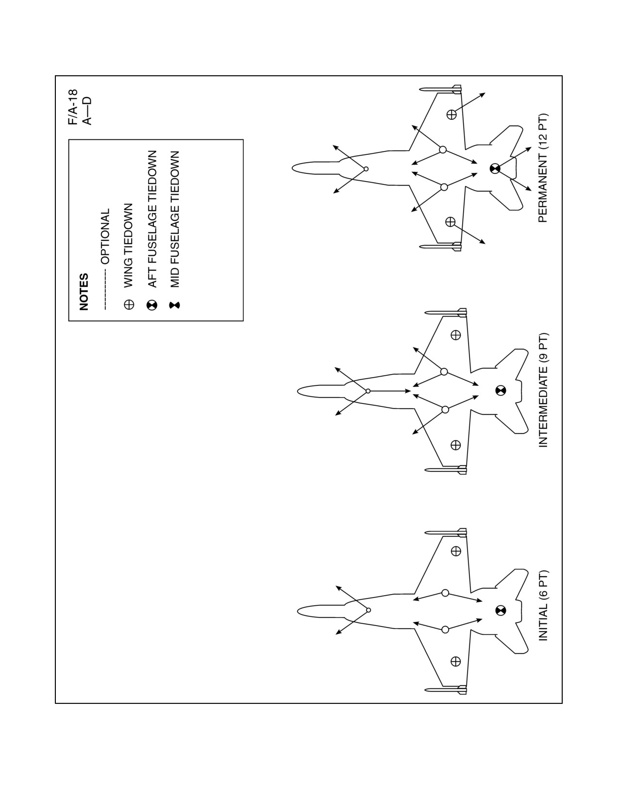
NAVAIR 00-80T-120
Figure 2-1. Tiedown Restraint (Sheet 1 of 8)
ORIGINAL
2-6
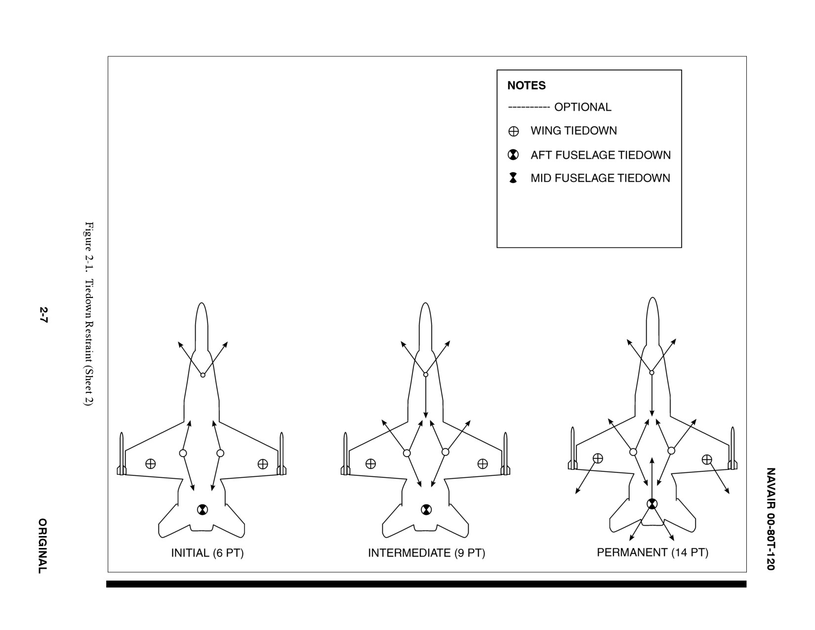
F/A-18
E/F/G
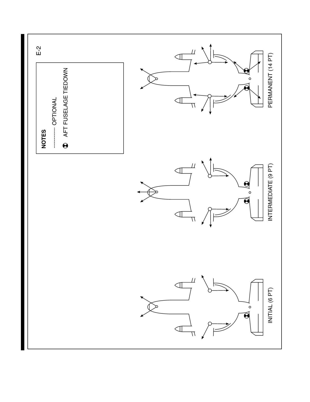
NAVAIR 00-80T-120
Figure 2-1. Tiedown Restraint (Sheet 3)
ORIGINAL
2-8
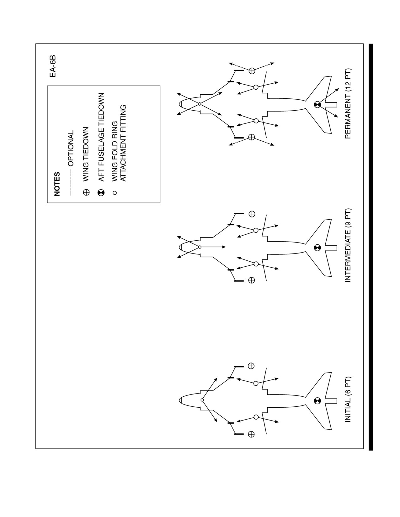
NAVAIR 00-80T-120
Figure 2-1. Tiedown Restraint (Sheet 4)
2-9
ORIGINAL
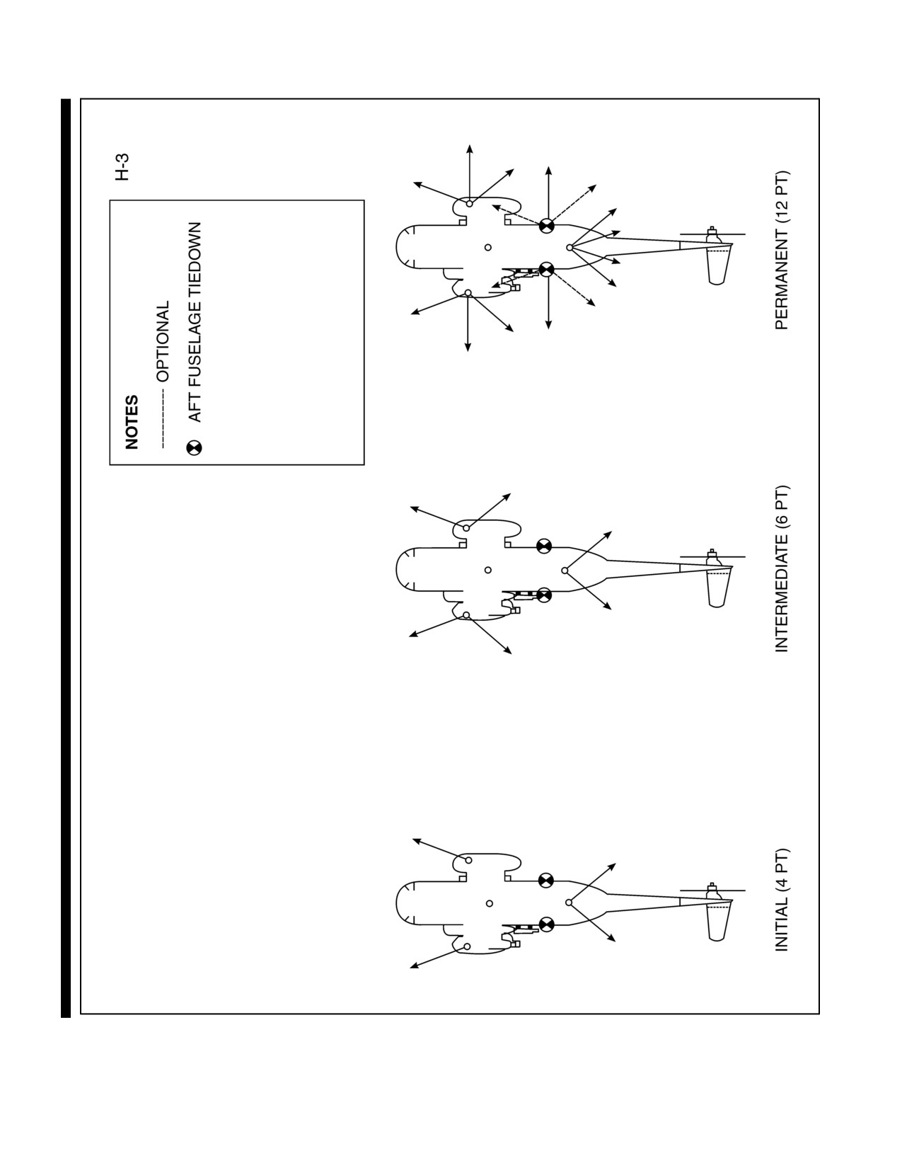
NAVAIR 00-80T-120
Figure 2-1. Tiedown Restraint (Sheet 5)
ORIGINAL
2-10
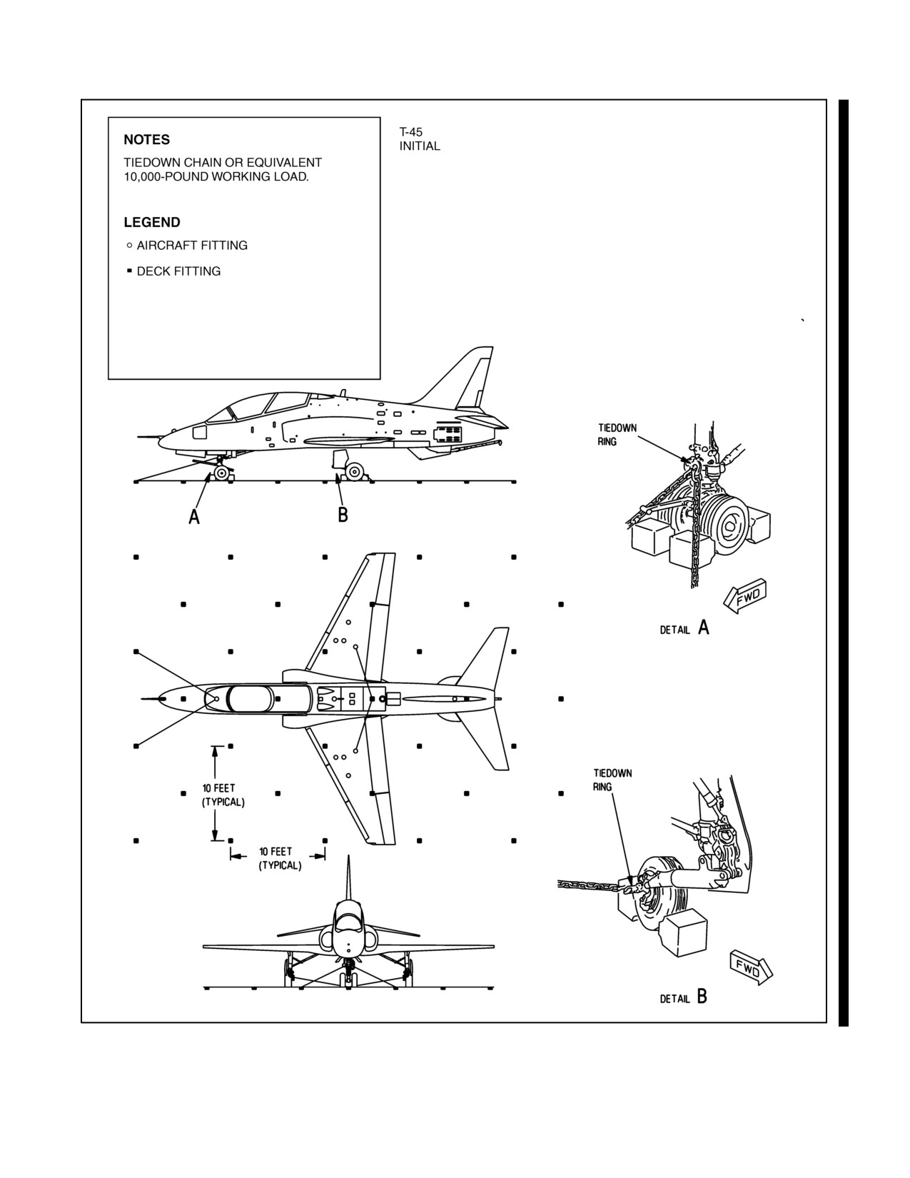
NAVAIR 00-80T-120
Figure 2-1. Tiedown Restraint (Sheet 6)
2-11
ORIGINAL
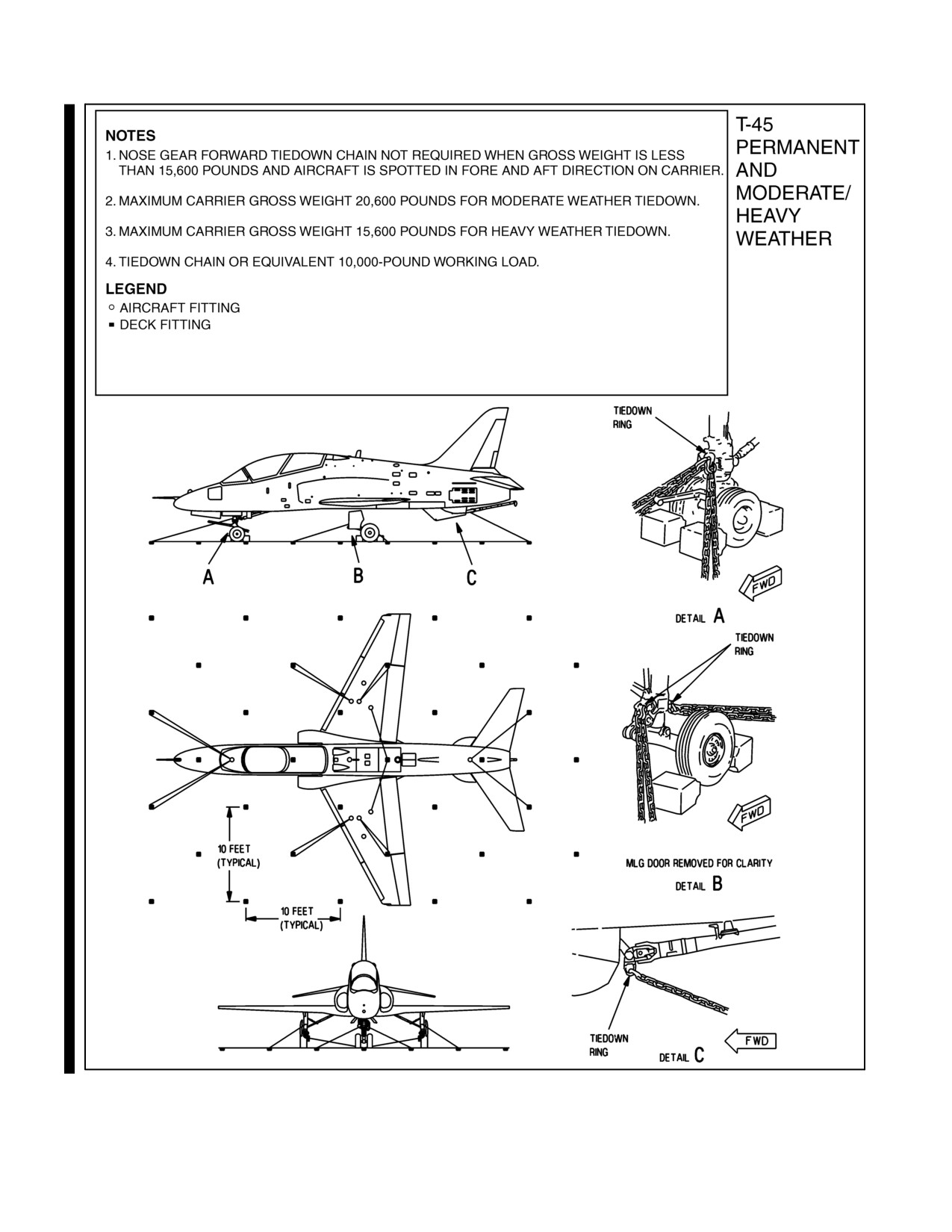
NAVAIR 00-80T-120
Figure 2-1. Tiedown Restraint (Sheet 7)
ORIGINAL
2-12
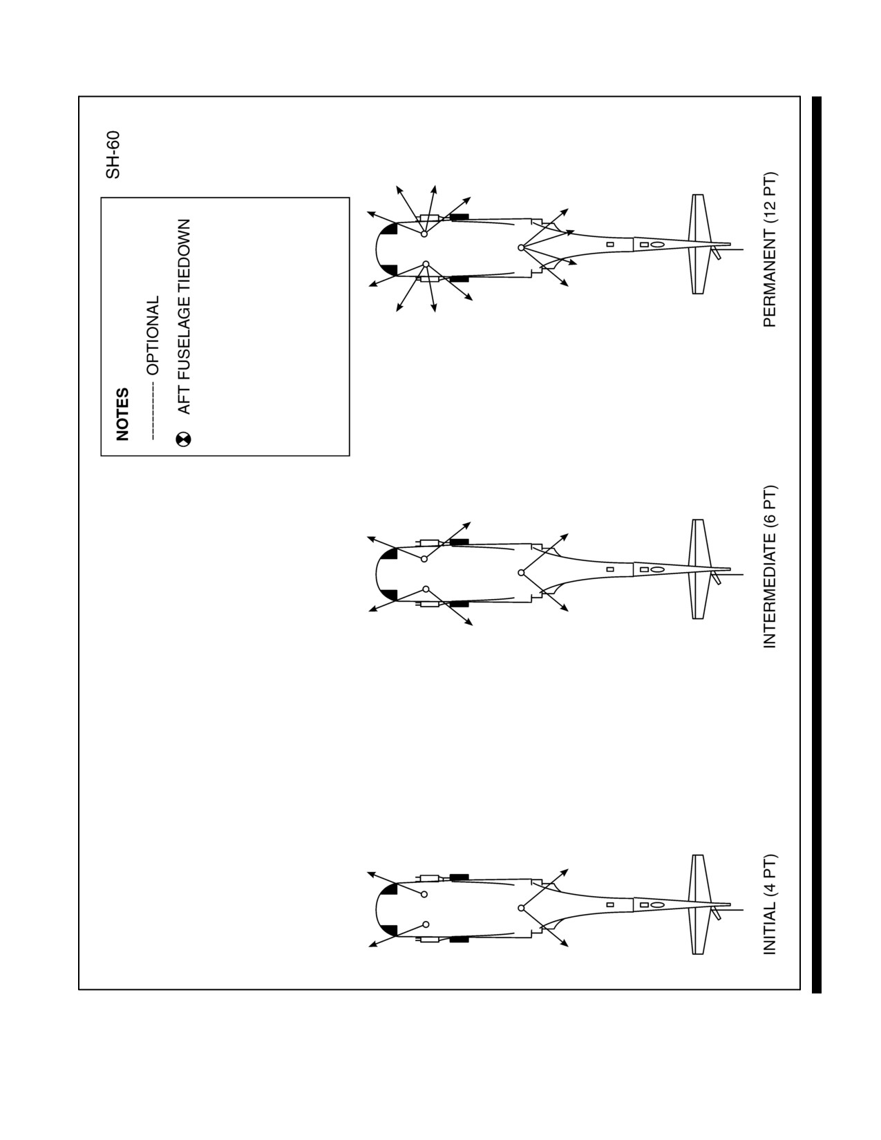
NAVAIR 00-80T-120
Figure 2-1. Tiedown Restraint (Sheet 8)
2-13
ORIGINAL
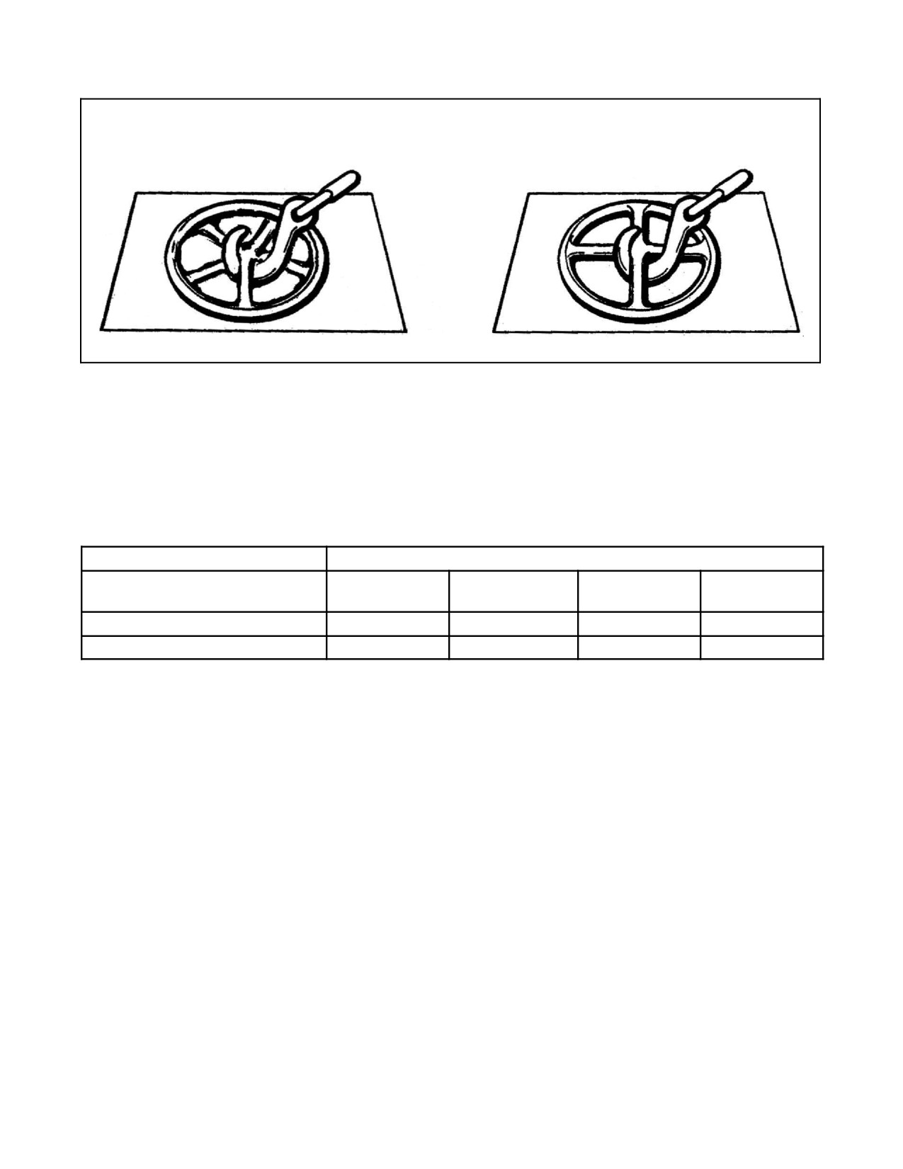
NAVAIR 00-80T-120
Five-Star Padeye
Four-Bar Padeye
Figure 2-2. Tiedown Installation
2.5
TIEDOWN REQUIREMENTS
Thefollowingtiedownconditionsareprovidedas aminimum guideforsafehandling operationsofshipboardaircraft
and may be increased as conditions necessitate.
SECURITY CONDITIONS
HEAVY
AIRCRAFT TYPE
INITIAL
INTERMEDIATE
PERMANENT
WEATHER
E-2*, C-2*, EA-6, F/A-18
6
9
12/14*
18/20*
AV-8, T-45, H-3, H-46, H-53, H-60
4
6
12
16
2.6
EQUIPMENT SECURITY
Aircraft handling/crash and salvage mobile equipment shall be parked with a minimum of two tiedowns (one
forward/one aft), rear wheel chocked, and parking brake set. Crash cranes shall be parked and secured with a
minimum of 13 tiedowns.
All rolling stock (e.g., air-conditioners, nitrogen carts, weapon carts) shall have parking brake set and a minimum
of two tiedowns tending fore/aft. When not at flight quarters, mobile equipment shall be “packed” fore-and-aft with
the vehicles at each end secured with two tiedowns. All vehicles shall have one rear wheel chocked and parking
brake set.
2.7
AIRCRAFT JACKING TIEDOWN SECURITY
The following procedures are required for shipboard aircraft jacking:
1. The ACHO or his representative shall approve jacking aircraft for maintenance.
2. Squadron personnel shall refer to the Maintenance Instruction Manual for procedures during jacking
operations.
3. When underway, the ACHO shall coordinate jacking of aircraft with the OOD.
ORIGINAL
2-14

NAVAIR 00-80T-120
2.8
HEAVY WEATHER AIRCRAFT SPOTTING
When a heavy weather spot requirement has been determined by the Commanding Officer, the ACHO shall ensure
the following:
1. A maximum number of aircraft shall be spotted on the hangar deck in such a manner to permit access to fire
stations at all times.
2. Remaining aircraft on the flight deck shall be spotted fore-and-aft as far from deck edge and the fantail as
possible and no farther forward than the bow JBDs.
3. The bow catapult JBDs shall be raised to assist in decreasing wind over deck.
4. Chocks shall be secured to wheels with 21-thread (or greater) manila line to prevent them from working free.
5. Maximum tiedowns shall be applied and parking brakes shall be set.
6. Deflating of struts and/or tires shall be accomplished as directed.
7. Fuel load adjustments shall be made as directed.
8. Aircraft integrity watches shall be doubled to function as two-man teams (buddy system).
Note
During heavy weather, aircraft integrity watches shall not venture onto
the flight deck without permission from the ACHO or his representative.
2-15/(2-16 blank)
ORIGINAL


NAVAIR 00-80T-120
CHAPTER 3
Preparations for
Flight Operations
3.1
TRAINING REQUIREMENTS
The Air Wing Commander shall coordinate all squadron predeployment training requirements with the ship.
Squadron commanders shall ensure that all personnel complete the lecture syllabus outlined below prior to initial
deployment. This applies equally to those squadrons/detachments that embark/operate for short-term workups, CQ,
transits, etc. These lectures need not be repeated before every deployment; however, squadron commanders are
responsible for providing refresher training as required for the safety of personnel and equipment. Ship’s company
personnel shall assist in this training; however, when this is not feasible, the most qualified squadron personnel shall
be utilized.
Note
The Air Wing Commander shall coordinate Civil Service and contract
personnel providing support to his Air Wing. Civil Service and contract
personnel not assigned to an Air Wing Commander shall coordinate
training with the cognizant CVN hosting department.
The Air Officer shall ensure that, in addition to the formal training required by type commanders, air department
personnel receive training as necessary to acquaint them with the peculiarities of the specific aircraft models being
deployed. Particular emphasis shall be placed on special aircraft handling requirements, flightcrew rescue
procedures, specific aircraft firefighting procedures, and aircraft salvage procedures. In addition, crash and salvage
personnel shall conduct a face-to-face briefing with squadron aircrew personnel, communicating what they expect
during an emergency egress.
Note
D All personnel, including Civil Service and contract, assigned any flight
deck duties shall first complete Flight Deck Familiarization PQS
(NAVEDTRA 43426-0 Series [Deck Familiarization PQS]). Only personnel
designated in writing by the Commanding Officer/Air Wing Commander may
be assigned to monitor and sign any PQS watch station as being completed.
This is in accordance with NAVEDTRA
43100.1 Series PQS Unit
Coordinators guide.
D All personnel shall pass the required annual flight deck physical (Civil
Service and Contract personnel shall meet the medical requirements
contained in the military annual flight deck physical). Written verification
of completed PQS (NAVEDTRA 43426−0 Series [Deck Familiarization
PQS]) training is required for all personnel via training jacket or
completion of PQS form contained in the NAVEDTRA 43426−0 Series
[Deck Familiarization PQS].
D A PQS-qualified person shall be within an “arms length” of any under
instruction (UI) personnel when accomplishing a given task.
Civil Service and contract personnel will be considered Flight Deck “current” when they have operated in a PQS
“qualified” status on a CVN Flight Deck within the previous 12 months.
3-1
ORIGINAL

NAVAIR 00-80T-120
3.2
PREDEPLOYMENT
3.2.1 General
Prior to getting underway, whether it be for an extended cruise or an operating period just off-shore, certain
preparations are required to ensure success. The following areas shall be reviewed in advance of every deployment.
3.2.1.1
Personnel Qualifications
Ensure that all personnel are properly qualified and that ongoing, comprehensive long- and short-range training
programs are provided. This program shall be planned to train and qualify current operators, and also to provide
cross-training and additional operators.
3.2.1.2
Safety Brief
Air Department Division Officers shall be responsible for ensuring that all division personnel receive thorough
flight/hangar and below-deck safety briefs prior to each deployment, and again after any 1-week-long in-port period.
3.2.1.3
Aircraft to Be Embarked
Ensure that a NATOPS Manual and Pocket Checklist for each type aircraft are available, and that pertinent portions
are reviewed by all Catapult and Arresting Gear Officers. Determine and make accommodations for any aircraft
service changes applicable to deploying aircraft that could effect launch/recovery parameters.
Squadron commanders shall submit to the ship via naval message prior to deployment a complete list of aircraft being
embarked. The naval message shall include; side numbers, PALS addresses, basic weights, certification that all
aircraft are FOD free, verification that all aircraft hoisting points/access panels are readily accessible and functional,
and any peculiarities in configuration that will affect handling, ordnance loading, or mission capability.
From each deploying squadron, obtain and review pertinent portions of squadron doctrine, SOP, air wing
TACNOTES, and air operations manual that refer to aircraft launch or recovery techniques or procedures.
3.2.1.4
Launch/Recovery Bulletins
Catapult and Arresting Officers shall review applicable bulletins quarterly and ensure updated information are
disseminated to respective operators.
3.2.1.5
Spare Parts and Accessories
The Air Officer or designated representative shall review the planned operating schedule and usage records to ensure
that adequate parts, material, equipment and accessories are onboard to support flight deck operations.
3.2.1.6
Squadron Brief
The Ship’s Operations Department is required to provide a Carrier Control Approach (CCA) brief to each deploying
unit prior to departure. It is recommended that the required Air Department brief, including launch and recovery
procedures, be given in conjunction with this brief. Appendix B is a recommended outline for a launch and recovery
brief. Details are covered elsewhere in this manual.
3.3
GENERAL REQUIREMENTS FOR FLIGHT QUARTERS
Flight Quarters entails the manning of stations required for the efficient and safe conduct of flight operations. The
ship shall be prepared to launch, recover, arm, fuel, and service aircraft, and at the same time be prepared to handle
aircraft crashes, fight aircraft or fuel fires, and render aid and assistance to injured personnel.
Flight deck personnel shall not consume intoxicating beverages within
12 hours of flight deck evolutions/operations.
ORIGINAL
3-2

NAVAIR 00-80T-120
Note
Commanders shall make available 8 hours for sleep during every 24-hour
period. Schedules will be made with due consideration for watch standing,
collateral duties, training, and off-duty activities.
Flight Quarters is a condition of readiness in which Air Department, Air Wing, Weapons Department, Operations
Department, Engineering Department, Combat Systems, and Medical Department personnel man specific equipment
and stations in support of flight operations. Flight Quarters stations for Air Department and Air Wing personnel are
the same as the General Quarters stations as prescribed in the ship’s Battle Bill, except that battle circuit phone talkers
and hangar deck and fuels repair parties shall not be fully manned during flight quarters unless specifically ordered
by the Air Officer. Flight Quarters may be treated as a separate evolution; however, when General Quarters is
sounded, all Flight Quarters stations shall be manned.
3.4
INITIATION OF FLIGHT QUARTERS
Flight Quarters stations shall be manned when directed. Flight Quarters is normally initiated over all circuits of the
1MC; an officer in the Air Department (usually the ACHO) shall request the Officer of the Deck (OOD) to sound
one of the Flight Quarters conditions. The same procedures shall be utilized to secure from flight quarters as are used
for manning.
3.4.1 Type of Flight Quarters
For efficiency of operations and to free personnel for other duties, Flight Quarters conditions may be modified.
3.4.1.1
Flight Quarters
Flight Quarters is the condition in which normal fixed wing and helicopter flight operations are conducted.
3.4.1.2
Flight Quarters for Respot
This is a condition set for the movement of aircraft about the ship.
3.4.1.3
Helicopter Flight Quarters
This is a condition set to operate helicopters.
3.4.2 Manning Flight Quarters Stations
When any form of Flight Quarters is called away, required personnel shall man their stations immediately. They shall
expeditiously perform functional tests and/or complete checkoff lists on equipment, and report via the appropriate
chain of command when the station is manned and ready, indicating the current status of existing equipment
discrepancies. All Air Department Divisions shall complete a Flight Quarters Checkoff list. A sample checkoff list
is included as Appendix C. Completed checkoff lists shall be submitted to the Air Officer via the ACHO prior to the
commencement of flight operations.
3.4.2.1
Preliminary Procedures — Air Officer
When flight quarters is sounded, the Air Officer shall ensure the following:
1. Procedures prescribed in applicable bulletins and instructions for inspection and preparation for operation of
aircraft launch and recovery equipment, aviation fuels system, aircraft elevators/doors, and crash/salvage and
firefighting equipment are meticulously followed.
3-3
ORIGINAL

NAVAIR 00-80T-120
Note
D When air department equipment becomes inoperable, the Air Officer, shall
inform the Commanding Officer and shall furnish an estimated time of
repair (ETR).
D Critical ALRE, aviation fuels systems, aircraft elevator, flight deck
lighting, crash and salvage crane/20K forklift, flight deck mobile
firefighting vehicles
(MFFV), and AFFF/saltwater CMWWD zones
adjacent to each other shall not be taken out of service without the
Commanding Officer’s permission.
D A decision to conduct flight operations when discrepancies are known to
exist in any of the above equipment shall be made only by the Commanding
Officer.
2.
A FOD walkdown shall be conducted prior to flight operations (minimum 1 day/1 night).
3.
The following flight quarters stations shall be manned and all equipment required during flight operations shall
be on-hand, inspected, and the pre-operational checklist completed. Any equipment, e.g., whip antennas,
flag/jack staffs, flight deck rails, that might interfere with flight operations, shall be stowed and secured:
a. Air Department.
(1) Primary Flight Control.
(2) Flight Deck Control and Flight Deck.
(3) Hangar Deck Control and Hangar Bays.
(4) V-2 Maintenance Office and all Aircraft Launch and Recovery Equipment.
(5) V-4 Maintenance Office and Flight/Below Deck Aviation Fuels Systems.
(6) Crash, Salvage and Rescue Equipment.
b. Other Departments. Man stations as required.
Note
The Air Boss shall ensure the following stations are properly manned during
aircraft launch, recovery, re-spot, engine turns, weapons loading, APU starts,
and refueling evolutions in accordance with NAVAIR 00-80R-14:
— MFFV(s) shall include an operator and two rescue personnel
during any of the above listed evolutions.
— During recovery, a line crew consisting of a crash and salvage
supervisor and two crewmembers shall be stationed at a
predesignated area for immediate response and to provide
equipment at the scene of a crashed or disabled aircraft.
4.
Crewmembers not assigned stations during actual launch/recovery evolutions shall be assigned responsibili-
ties to provide designated equipment in the event of an on-deck emergency.
5.
The mobile crash crane and forklift shall be started and warmed up at the commencement of each recovery
phase of flight operations and remain running throughout the recovery.
3.4.2.2
Manning and Starting Aircraft
Flight crews shall man their aircraft as directed. When ordered to man, they shall proceed to their aircraft via
designated route and conduct preflight inspections as expeditiously as safety permits.
ORIGINAL
3-4

NAVAIR 00-80T-120
In a pending emergency, the Air Officer shall notify flight and hangar deck personnel by use of the 3MC and 5MC
announcing systems and flight warning alarm. The crash alarm shall be sounded to notify flight deck personnel of
an actual on-deck aircraft mishap.
Note
The flight warning and crash alarms shall be used only for the purposes
described above.
3.5
PLANE GUARD HELICOPTER/DESTROYER
A plane guard helicopter/destroyer shall be provided per existing directives. The plane guard helicopter/destroyer
shall monitor land/launch frequency; radio contact (if Emission Control [EMCON] condition permits) shall be
established prior to launch/recovery to ensure that vital information can be passed to the helicopter/destroyer
immediately, if required.
3.6
ALERT CONDITIONS
Alert conditions shall be set as called for by the Carrier Strike Group Commander or as published in the Air Plan.
Conditions of readiness and the requirements for each condition shall be as specified in NAVAIR 00-80T-105.
3.7
HAZARDS OF ELECTROMAGNETIC RADIATION TO ORDNANCE (HERO)
Conditions shall be set as required by the flight deck ordnance crew. The Officer of the Deck (OOD) shall have the
word passed over all 1MC circuits when HERO is set or relaxed; HERO beacon shall be illuminated when applicable.
3.8
FLIGHT/HANGAR DECK LIGHTING
All installed flight deck, landing area, and runway lights shall be maintained in an operable condition and checked
for proper operation and security of deck fixtures daily at least 1 hour prior to sunset and prior to any night or IMC
recoveries. These lighting systems, including runway edge, centerline, and athwartship lights; landing area lights;
vertical bar drop lights; and sequenced flashing centerline lights shall be utilized for all night or IMC recoveries. This
requirement may be waived by the carrier Commanding Officer if operational circumstances so dictate. Visual
landing aids General Service Bulletin No. 8 (current revision) shall be consulted for specific ship lighting
configuration and orientation.
Minimum intensity floodlighting consistent with safety shall normally be used on the flight deck between sunset and
sunrise for all flight deck evolutions during flight quarters. Carriers having sodium vapor and/or flight deck
floodlighting shall, when the tactical situation permits, have the SOX or white floodlights turned on for launches,
recoveries, and re-spots. Circumstances that preclude the use of SOX or white floodlights shall be evaluated as to
necessity for lack of illumination, as reduced efficiency on the flight deck, increased crunch potential, increased
bolter/waveoff rate, and decreased recovery rate are to be expected. Safety aspects of the entire flight deck evolution
and the risk associated with non-use of SOX or white lighting shall receive due consideration in arriving at a decision
to restrict use.
White lights may be used in the hangar deck to enhance aircraft maintenance and handling efficiency and safety. When
restrictive lighting measures are in effect on the flight deck, due regard shall be taken to ensure masking of the white
hangar bay lights. These conditions include, but are not limited to, darken ship and transit of restricted or high traffic
density waters. Consideration shall be given to closing hangar bay doors if conditions so warrant. Aircraft running
lights shall remain extinguished between the hours of sunset and sunrise except as required during launch and
recovery operations.
3.9
AIR PLAN
In order for Strike Operations to prepare an air plan that is within the capabilities of the air wing and all supporting
activities, the following shall be reported on a regular basis:
1. The status of all embarked aircraft. This report shall be delivered to the Bridge, Carrier Strike Group
Commander, Flag Operations, Air Operations, and the Air Department. The report shall include expected
changes in status and test flight requirements for the following day.
2. An up-to-date ordnance load plan.
3-5
ORIGINAL

NAVAIR 00-80T-120
The air plan shall be distributed on the evening before the scheduled operations. When the air plan is delayed, the
Strike Operations Officer shall provide advance information to allow preparations for the first launch. As a minimum,
a rough air plan shall be hand-delivered to Flight Deck Control, PriFly, Air Operations, Ordnance Handling Officer
(OHO), and Air Wing Weapons Officer (CAG Gunner) and Maintenance representative.
3.10
ORDNANCE LOAD PLAN
No changes shall be made to the ordnance load plan without approval by the Strike Operations Officer. The Air Wing
Weapons Officer or his designated representative shall visually inspect each aircraft for proper ordnance load as per
the Air Plan. Discrepancies shall be brought to the attention to the Aircraft Handling Officer immediately.
3.11
FLIGHT DECK UNIFORMS
3.11.1 Wearing of Flight Deck Uniforms
Control and issue of flight deck clothing (see Appendix H, Figure H-1) shall be enforced by the Air Officer and Carrier
Air Wing Commander (CAG) for all personnel working on the flight deck.
A complete flight deck uniform shall consist of TYCOM approved flight deck trousers, flight deck jersey, flotation
device, steel-toe boots, leather gloves, helmet with goggles and jersey corresponding in color to that of their
respective detail and with their billet title on the jersey and flotation vest. Coveralls and the Navy Working Uniform
(NWU) are not authorized to be worn on the flight deck at any time while flight deck operations are being conducted.
Personnel assigned specific duties shall wear the appropriate flight deck gear per Figure H-1.
3.11.2 Special Clothing
The Supply Officer shall procure, store, and issue special clothing per current allowances and standard accounting
procedures.
Special clothing shall be drawn from the Supply Officer for the Air Department and Air Wing personnel, as prescribed
by ship’s instructions. It shall be reissued to individuals on an allowance/need basis via the Division Officer, who
accounts to the Air Officer and Carrier Air Wing Commander by means of sub-custody receipts.
Special clothing shall be worn only when prescribed by the Air Officer or CAG.
3.12
AIR-TO-SHIP COMMUNICATIONS
Minimum of two (2) Air-to-Ship Radio communication devices, one for the Air Boss and one for the Mini-Boss, with
connections for two headsets/handsets each. At a minimum, the communication devices shall provide access to
CATCC Final A and Final B UHF Radio Circuit Transceivers and two Dedicated/Backup Air-to-Ship UHF
transceivers. The Dedicated/Backup transceivers shall be capable of selecting required frequency channels from
primary flight control.
ORIGINAL
3-6

NAVAIR 00-80T-120
CHAPTER 4
Catapult Launching Procedures
4.1
GENERAL
This section is to be used in conjunction with Aircraft Launching Bulletins, NAVAIR and COMNAVAIRFOR
directives.
4.1.1 Operational Safety Warnings
4.1.1.1
General
1.
The launching of today’s high-performance aircraft is a complex and demanding operation involving various
inherent dangers. Personnel engaged in the operation of the launch equipment shall be thoroughly trained and
qualified for the launch operation. The procedures and safety precautions contained in this manual shall be
complied with. Disregard for these procedures, cautions, or safety warnings may create hazards more
dangerous than those previously mentioned.
2.
Safety is an all hands concern; as such, all hands shall be thoroughly familiar with this manual and applicable
instructions, procedures, and safety precautions. Further, all hands shall also insist on strict adherence to
established safety precautions by all others not having direct access to this manual.
3.
Personnel having reason to suspect the safe operational/material readiness condition of the launch equipment,
deck gear accessories, the aircraft, or the aircraft hook-up shall immediately cause the launch to be suspended
by either suspending the catapult themselves, or by informing the catapult officer or other personnel capable
of suspending the catapult.
4.
Prior to operational actuation of launch/recovery equipment, an inspection of equipment shall be made to
locate any possible misplaced tools, rags, machine parts, etc., that would interfere with proper functioning of
equipment.
5.
During launching operations, the voice communication system shall be used only for essential communica-
tions, to ensure that signals between operators are not misunderstood.
6.
During any type of launching, live steam escapes from the track and brake areas. As this steam can cause
scalding of exposed areas of the body, personnel in the area shall avoid contact with it. When the catapult is
in operating status, exposed metallic parts, such as track covers, launching and exhaust valves, and steam
supply piping, may be hot enough to burn exposed areas of the body on contact. Therefore, operating personnel
with duties in these areas shall be equipped with required protective clothing.
7.
Hearing protection shall be worn in all areas of high noise level.
8.
Personnel who work in areas where there is a danger of contact with “live” steam or hot metallic surfaces shall
wear appropriate protective clothing to prevent burns.
9.
All loose gear and tools shall be kept clear of all equipment.
10.
Operational/maintenance equipment pressures shall be maintained at predetermined settings.
11.
All catapult, arresting gear, and VLA spaces are RESTRICTED areas; unauthorized personnel shall not be
allowed in these spaces at any time. RESTRICTED signs shall be posted.
Note
The catapult shall not be operated when the Launching Officer and the
Monitor/Deckedge Operator are under instruction at the same time.
4-1
ORIGINAL

NAVAIR 00-80T-120
4.1.1.2
Flight Deck
The following precautions shall be observed:
1.
During launch operations, no personnel other than those required by applicable operating instructions shall
be on the flight deck, catwalks, sponsons, or in the launch area without the expressed permission of the Air
Officer. It shall be the responsibility of the Catapult Officers, Flight Deck Officer, and Flight Deck Supervisors
to ensure compliance.
2.
All personnel who are required to be on the deck in the launch area and who do not have a specifically assigned
station shall remain in a safe area.
3.
Any person who observes any unusual condition during the launch, such as objects falling from or striking
the aircraft, shall immediately inform the Catapult Officer.
4.
Personnel required to be in the catwalks shall duck below flight deck level during actual aircraft launch.
5.
No one shall enter the launch area to effect repairs, or for any other reason, until positive clearance has been
obtained from the Catapult Officer.
6.
During night operations, the pre-launch check of catapult components or aircraft launching intervals shall not
be speeded up. Sufficient time shall be taken to double-check each step to prevent possible accidents due to
faulty hook-ups, misinterpreted signals, and other causes.
7.
The shuttle or grab shall not be advanced or retracted along the track until the Catapult Officer is present at
his station, and the track slot and surrounding areas have been inspected and found to be clear.
8.
After tension is taken on an aircraft having a launch bar selector switch, the pilot shall not place the launch
bar selector switch in the OFF, ABORT, or RETRACTED position until he has advanced the aircraft’s throttles
in accordance with the specific aircraft’s NATOPS manual.
9.
When the catapult is in use, no one shall go in front of the shuttle or forward of an aircraft that is ready to be
launched. No one except authorized operating personnel shall be permitted in catwalks or on the flight deck
forward of the catapult battery position.
10.
Personnel shall not go under the aircraft until the aircraft is throttled back.
11.
During emergency situations when moving or towing the shuttle or aircraft, crewmen shall stand clear.
12.
The catapult crew shall remain clear of the aircraft during arming operations.
4.1.1.3
Fire Prevention in Catapult Spaces
High-pressure fluids, high temperatures, and close proximity to flight deck combustibles greatly increase the
possibility of fire in the steam catapult system. Combustible and flammable liquids or materials shall be kept away
from the heated catapult parts to reduce the possibility of fire and explosion. Adequate ventilation shall be provided
below deck to prevent the buildup of explosive gases. After every fire and before resumption of flight operations,
a thorough inspection of the affected portion of the catapult and associated equipment shall be made. In addition, the
entire crew shall be made aware of the hazards to safe flight operations and of other potential dangers, should there
be a recurrence of the same type of fire in the future. To minimize the causes of fire and the extent of fire damage,
particular attention shall be continually paid to the following precautions:
1. Training of all personnel in the proper firefighting procedures.
2. Procurement, proper stowage, and ready availability of effective firefighting equipment.
3. Periodic checkouts of automatic and semiautomatic steam smothering systems to ensure proper operation.
Note
At each catapult steam smothering valve location, valve enclosure boxes
shall be painted with 1-inch black and white alternating stripes. Deck and
wheel stop coaming shall be in accordance with VLA General Service
Bulletin No. 8.
4. All spaces kept in a clean condition, especially the trough. Clean up any spillage immediately.
ORIGINAL
4-2

NAVAIR 00-80T-120
5. Bow catapult slot seals shall be installed prior to any fixed wing refueling/defueling evolutions. Waist catapult
slot seals shall be installed immediately after securing from flight operations.
6. Slot seals shall be removed prior to launching or recovering a helicopter.
7. Repair of lagging breaks in excessively high temperature areas.
8. A qualified Catapult Steam Watch shall be posted during non-operating hours have been thoroughly
indoctrinated in the proper procedure for reporting and containing a fire until competent assistance arrives.
4.1.2 Aircraft Launching Bulletins
These bulletins include special instructions to the flight deck crew, the pilot and the Catapult Officer. It is imperative
that all Catapult Officers and pilots be completely familiar with all applicable bulletins. Aircraft Launching Bulletins
are issued by the Naval Air Warfare Center to provide launching data for catapult and aircraft, required aircraft
launching accessories, list of effective bulletins, etc.
Aircraft launching data are prepared to set forth uniform instructions for launching within the performance capability
of the aircraft and the catapults. The minimum take-off airspeed for launching, as listed in the Aircraft Launching
Bulletins is determined by the Aircraft Test Directorate (Carrier Suitability Branch) of the Naval Air Warfare Center,
while conducting the carrier suitability portion of the Board of Inspection and Survey (BIS) trials. This minimum
take-off airspeed may be limited by aerodynamic stall; thrust available for acceleration after launch; loss of aileron,
elevator, or rudder control; time required to rotate to a flying attitude after launch; control effectiveness and pitching
rates in an accelerated stall; overly stringent pilot techniques required; or stick forces or movement beyond limits
in event of an aircraft systems failure. These data, which establish the minimum conditions that shall exist prior to
the launch and upon which the launching bulletins are based, enable the Operational Commanders to know the
ultimate capability of the launching equipment.
Thus, a measure of the safety involved in launches made above minimum conditions can be effected. To ensure
additional safety, operations should be conducted above the minimum conditions. Ten to 15 knots in excess of
minimum take-off airspeed is optimum for bow-launched aircraft. Fifteen knots is recommended for waist aircraft.
Launch charts shall be prepared and aircraft may be launched within this range without any special clearance.
However, should operational requirements that require launching under 10 knots excess exist, the Commanding
Officer shall authorize each launch, and the pilot shall be advised of the anticipated excess.
The Aircraft Launching Bulletins contain the governing instructions for launching specified aircraft from specified
catapults. An Aircraft Launching Bulletin does not authorize aircraft launching, but delineates the conditions under
which the aircraft can be launched when authorization has been received. Authority to launch and restrictions for
launching the aircraft are contained in the applicable NATOPS Flight Manuals. Compliance with the provisions of
both the Aircraft Launching Bulletins and the NATOPS Flight Manuals is mandatory for safety of operations. An
activity shall consult both documents prior to commencing aircraft launches.
4.1.2.1
Bulletin Identification Number
Aircraft Launching Bulletins are assigned identification code numbers that indicate equipment applicability and
subject matter. The number preceding the dash indicates the catapult type or catapult type and ship if the catapult on
one ship differs in performance from a catapult of the same type on another ship. For example, the 31 Series Bulletins
pertain to the C-13-2 catapults on USS ABRAHAM LINCOLN (CVN 72). The 24 Series pertain to the C-13-1
catapults on USS DWIGHT D. EISENHOWER (CVN 69).
When the number zero precedes the dash, the bulletin is applicable to all steam catapults. The numbers following
the dash identify the subject matter as follows:
1.
0-10 Aircraft Launching Bulletin. This bulletin outlines the basic content of the various bulletins, how they
were prepared, and specific instructions in their use.
2.
0-11 Aircraft Launching Bulletin. This bulletin is issued quarterly and is a list of bulletins in effect, superseded
or canceled. Interim bulletin revisions that are promulgated by message or speedletter are also listed in this
bulletin. The 0-11 bulletin should be carefully reviewed in order to maintain a complete up-to-date file of all
applicable aircraft launching/recovery bulletins. As changes and revisions are received, applicable information
shall be promptly disseminated.
4-3
ORIGINAL

NAVAIR 00-80T-120
3.
0-12 Aircraft Launching Bulletin. This bulletin is a list of aircraft launching accessories required for all aircraft.
Information also includes National Stock Number (NSN), Part Number (P/N), usage limitations, color codes,
and the effective Catapult Deck Gear and Accessories Service Bulletin for each aircraft type. Changes that arise
prior to revision of the 0-12 Bulletin will be indicated in the 0-11 Bulletin.
4.
0-15 Aircraft Launching Bulletin. This bulletin provides crosswind limitations for both catapult and deck
launches for each aircraft. Additional crosswind information includes trim settings, excess end speed
requirements, and a discussion of off-center spotting.
5.
0-56 and Subsequent Zero Dash Aircraft Launching Bulletins. These bulletins contain special instructions for
launching specific aircraft, which include special instructions to the Launching Officer, flight deck crew and
pilot, launch precautions, corrections for minimum wind-over-the-deck, trim settings, off-center spotting
limitations, and other safety precautions. The number following the dash indicates the specific aircraft type.
For example, the 0-69 series bulletins pertain to the TA-4F/J aircraft; the 0-71 series bulletins pertain to
F/A-18 E/F aircraft, etc.
6.
9-56, 12-56, etc., and Subsequent Aircraft Launching Bulletins. These bulletins contain wind-over-the-deck
data for launching specific aircraft from specific catapults onboard specific aircraft carriers. Remember, the
number preceding the dash indicates the specific carrier(s). The number following the dash indicates the
specific aircraft type. For example, the 24-71 Bulletin applies to the F/A-18 E/F plus series aircraft launched
from the C-13-1 catapult onboard the USS DWIGHT D. EISENHOWER (CVN 69); the 32-67 Bulletin applies
to the F/A-18 aircraft launched from the C-13-2 catapults onboard the USS ABRAHAM LINCOLN. From
these examples the 71 indicates F/A-18 E/F and 67 indicated F/A-18 aircraft.
4.1.2.2
Bulletin Revision Identification
Revisions of aircraft launching bulletins are identified by a revision letter following the bulletin number and by a new
date corresponding to the date of the revision. The first revision of a bulletin is identified by the letter A; subsequent
revisions follow in alphabetical order (e.g., 24-67H of October 2004, 24-71B of 07 November 2006, etc.). The portion
of the text affected by the current revision is indicated with an asterisk. Revision identification is the same for all
bulletins except the 0-11 Bulletin. The first issue of each year is identified with the basic number 0-11-07 and each
subsequent quarterly revision has a suffix number added to the basic number (e.g., 0-11-07-1 of 01 January 2007,
0-11-07-2 of 01 March 2007, etc.).
4.1.2.3
War Emergency Bulletins
Aircraft launching bulletins that have a Q prefix in their numbers are designed as War Emergency Bulletins. Such
bulletins authorize launching aircraft at higher gross weights or capacity selector valve (CSV) settings than are
currently permitted by the NATOPS Flight Manual and by the Aircraft Launching Bulletins. Routine carrier launches,
launches under simulated war emergency conditions, and training launches shall be made under the authorization and
restrictions delineated in the NATOPS Flight Manual and by the Aircraft Launching Bulletins.
Use of War Emergency Bulletins may cause the aircraft catapulting strength
design limit to be exceeded by as much as 15 percent. An aircraft logbook
entry is required as specified in the applicable Bulletin.
ORIGINAL
4-4

NAVAIR 00-80T-120
4.1.3 Launch Bulletins
The information presented in the minimum required Wind-over-the-deck
charts in the current launch bulletins is easy to use. Aircraft launching
bulletins shall not be converted to “quickie” or “pocket” launch charts.
The following parameters shall be considered in the preparation of launch charts:
1. Wind-Over-the-Deck.
a. WOD requirements for launch and recovery are determined from Aircraft Launch and Recovery Bulletins.
The Air Officer shall advise the bridge 30 minutes prior to launch time of minimum WOD to provide
15 knots excess for the most critical aircraft.
b. Wind required for helicopter operations shall be per individual helicopter NATOPS manuals.
c. The wind-over-the-deck range should include the normal operating winds, plus low winds for those aircraft
that would conceivably be launched under these conditions.
d. Winds shall be indicated in 2-knot increments.
2. Weight Range. The weight range should cover the minimum through the maximum weights for carrier
operations including carrier qualification weights.
3. Density Altitude.
a. Obtain from meteorology the current density altitude and correction from the current 0-11 ALB.
4. Excess Endspeed.
a. Ten to 15 knots is the minimum endspeed excess range. The actual programmed excess, within this range,
shall be determined by the Commanding Officer after consideration of all factors involved (e.g., aircraft
strength, stability, pilot experience level, operating conditions, etc.).
Aircraft launchings at high excess endspeeds impose limitations as critical
as those imposed by launches made at or near minimum conditions.
b. Whenever possible, aircraft excess endspeeds shall fall within the 10- to 15-knot limitations. Excesses
within these limitations are not only considered optimum, but will provide a consistency to the Air Wing
pilots and result in improved Air Wing proficiency and safety.
4.2
AIRCRAFT LAUNCHING FAMILIARIZATION
Every Catapult Officer shall know, or have readily available, a considerable amount of information pertaining to each
type of aircraft to be launched. Much of this information is taken directly from the Aircraft Launching Bulletin Zero
Dash Series (e.g., required trim/flap settings, maximum off-center spotting distances, maximum permissible excess
airspeeds, and other special instructions). In addition, every Launching Officer shall be intimately familiar with the
peculiarities and idiosyncrasies of each aircraft type.
Either an experienced Catapult Officer/Catapult Safety Observer, or qualified squadron personnel shall give a
pre-launching familiarization inspection of each aircraft. Items to be covered should include position of wing locks,
4-5
ORIGINAL

NAVAIR 00-80T-120
flap and trim positions and indications, access doors that are most commonly used, ejection seat pins and location
of arming indicators, and other such pertinent information.
This chapter, in conjunction with the aircraft launching bulletins should give all necessary information pertaining
to the aircraft to be launched. Refer to the Aircraft Launching Bulletin No. 0-15 for crosswind limits, and use the
specific aircraft Zero Dash Bulletins for spotting limits, trim, nose wheel cock limits, and other information.
4.2.1 EA-6B
4.2.1.1
Pre-Launch
1. Nose wheel steering is limited. A tag lock disengages the steering when the nose wheel is turned past 56° from
the center position. Sharp turns shall be avoided. To prevent damage to the nose gear, the launch bar shall not
be in the locked “up” position after the trail bar is attached to the aircraft.
2. The aircraft is very difficult to push back due to the high engine RPM at idle. Care should be taken not to over
run the “Wye” area.
3. The location of the intakes in relation to the nose strut makes this aircraft one of the most dangerous in the fleet.
If it becomes necessary to take the plane off the catapult, the Launching Officer/Catapult Safety Observer shall
take positive control of the buffer aft and the pushback evolution.
4. The launch bar has a tendency to come up prior to tensioning (See E-2/C-2 pre-launch).
CAUTION
Ensure the launch bar is clear of the shuttle before allowing the buffer aft
sequence to commence. However, the launch bar shall not be locked in the
up position. Buffering with the launch bar locked may damage the nose gear
mechanism.
5. There are several model, external stores, engine, and trim combinations. Make certain the proper launch
bulletin and launch charts are used.
6. Wing flaps and slats cannot be extended unless the wings are spread. EA-6B aircraft are susceptible to wing
damage when wings are folded. When spotted aft of the JBDs with aircraft on the catapult turning up, the
EA-6B wings shall be spread.
4.2.1.2
Functional Check Flight (FCF) Engine Tests on the Catapult
Note
D Only the FCF engine checks are allowed utilizing the catapult. The FCF
engine checks should only be performed when the aircraft has “intent to
fly”. All other engine maintenance checks shall be performed in the
approved designated areas.
D Follow the normal launching and hook−up procedures and safety checks,
with the additions as outlined in steps 1. thru 10., when the FCF engine test
is to be performed.
1. Prior to the aircraft taxiing into the approach tracks, the piston assembly shall be maneuvered forward into the
water brakes. When the aircraft is ready, signal LOWER LAUNCH BAR in the wye plate area and install the
holdback bar. The appropriate holdback bar installation checks shall be followed. Taxi the aircraft through the
approach tracks until the buffer hook is fully bottomed forward. Ensure the release element in the holdback
bar is properly seated.
ORIGINAL
4-6

NAVAIR 00-80T-120
Because the aircraft’s nose gear is not anchored by the spreader, the topside
petty officer shall stand at a safe distance (clear of the catapult safe shot line)
and observe the aircraft’s wheels for sliding sideways during engine testing.
2. Signal to the aircraft to turn up engines to MRT power. Both engines shall be turned−up simultaneously to
reduce the risk of the aircraft sliding sideways. Engine turn−up shall be at a constant rate to avoid damage to
the buffer hook assembly.
3. During this time, the engines will be tested in accordance with the applicable EA−6B NATOPS.
4. At MRT power, there shall be a 90−second restriction on the duration of these checks. If checks are not
complete within the 90−second period, both engines shall be powered down to IDLE and the JBD allowed to
cool for 30−seconds. After the JBD cool−down, both engines shall be turned up simultaneously to continue
the FCF checks. This process shall be repeated until the FCF checks are completed.
5. At the completion of the checks, aircraft engines shall be powered down to IDLE, and a JBD cool−down period
for a minimum of 30 seconds shall occur prior to aircraft hookup to the spreader.
CAUTION
If it is suspected that the aircraft’s wheels slid sideways during the test, the
aircraft shall be suspended from the catapult and the holdback bar removed
from service to undergo an inspection in accordance with MIP 5871/RLA
MRC R−16 NOTE 6. The release element shall be discarded.
6. At the completion of the checks, the Topside Side Petty Officer shall MANUALLY RAISE the launch bar
before the piston assembly is maneuvered aft.
7. The holdback bar shall be inspected to verify that the release element is still properly seated.
8. Once the piston assembly has been maneuvered aft, normal hook−up procedures shall be followed.
9. The FCF check, by itself, is not to be counted against the holdback bar service life. If the aircraft is launched
following a FCF check, the holdback bar shall have one cycle counted against its service life. If the aircraft
did not launch, no cycles shall be counted on the holdback bar. If the aircraft did not launch, remove the release
element and inspect it in accordance with step 6.
10. Any successive launches shall follow the latest launching bulletin for JBD cool−down periods and restrictions.
4.2.1.3
Launch
1. The catapult grip locks the nose strut. Pilots should be briefed to ensure the use of the catapult grip for the entire
catapult stroke. Catapult grip is visible to the Launching Officer when the aircraft is on the starboard catapult.
2. The pilot is seated in the port side of the cockpit. The Launching Officer shall vary his position accordingly
to ensure all his signals may be seen by the pilot.
3. Avoid standing in a position where the wing tip passes overhead. Aircraft is equipped with wing-tip speed
brakes, which may be inadvertently actuated on stroke.
4-7
ORIGINAL

NAVAIR 00-80T-120
4.2.2 T-45
Refer to F/A-18, paragraph 4.2.4.1 for pre-launch and launch procedures.
T-45 aircraft requires a higher engine thrust to achieve a full NGL buffer
stroke. During this process, TSPO shall maintain situational awareness and
conscious effort to avoid jet intake areas. Once the RRHB engages the
buffer hooks, the TSPO and UI (if applicable) shall assume crouching
position away from the intake and remain crouched until tension is taken,
exercising extreme caution while exiting from under the aircraft.
4.2.3 E-2/C-2
4.2.3.1
Pre-Launch
1. The launch bar has a tendency to come up once the aircraft is in the holdback and prior to tension. Maintaining
slight thrust keeps tension on the system, preventing the launch bar from coming up, and the requirement for
hands or feet to be in the area during tensioning is eliminated. The launch bar shall not be in the locked-up
position after the holdback has been attached to the aircraft.
2. After the trail bar has been removed, ensure the launch bar is locked up prior to backing aircraft on the catapult.
3. On the C-2 aircraft, ensure main gear struts are extended prior to taking tension.
The pilot of C-2 aircraft shall receive the anticipated end airspeed and flap
setting from the Catapult Officer.
4. The E-2/C-2 pilot, upon receipt of the tension-up signal, shall place the power levers at FLT IDLE and apply
2,500 to 3,500 IHP. The Catapult Officer/Catapult Safety Observer then receives the aircraft from the director
and ensures that the Topside Safety Petty Officer is clear of the aircraft and has given the GO signal. The
Catapult Officer then gives the turn-up signal to the aircraft, at which time, the pilot places the power levers
at MAXIMUM POWER.
T-56 engine RPM decay or flameout can result from ingestion of turbojet
exhaust. E-2/C-2 aircraft shall not be launched from the waist catapults
when turbojet aircraft are spotted on or along the No. 2 catapult, or along
the foul deck line forward of the waist catapults with the aircraft exhaust
blowing to the port side. This includes aircraft in the de-arm area blowing
turbojet exhaust to port. These restrictions apply only to exhaust from
turbojet aircraft.
4.2.3.2
Launch
Ensure the areas around the prop arcs are clear of any objects, which may be drawn into the prop arc during engine
turn-up or during catapult stroke.
ORIGINAL
4-8

NAVAIR 00-80T-120
4.2.4 F/A-18 Series (A thru G)
4.2.4.1
Pre-Launch
1. The launch bar is controlled from the cockpit. Always have the nose wheel aligned, fore and aft with the
aircraft, before giving the launch-bar down signal. Normally a 4-second delay follows completion of control
wipeout before the pilot gives his final salute.
2. The launch bar control shall be in the up position prior to launching. There is no external indication when the
launch bar control has been selected to the up position.
All visual launch bar mispositioning procedures/cues shall still be closely
followed during each aircraft tensioning sequence for all aircraft types.
Mispositioning of the aircraft launch bar may result in the launch bar
separating from the shuttle spreader during the launch.
3. The Aircraft Director shall pass control to the Launching Officer/Catapult Safety Observer after the Topside
Petty Officer has cleared the aircraft.
4.2.4.2
Functional Check Flight (FCF) Engine Tests on the Catapult
Note
D Only the FCF engine checks are allowed utilizing the catapult. The FCF
engine checks should only be performed when the aircraft has “intent to
fly”. All other engine maintenance checks shall be performed in the
approved designated areas.
D Follow the normal launching and hook−up procedures and safety checks,
with the additions as outlined in steps 1. thru 12., when the FCF engine test
is to be performed.
1. Prior to the aircraft taxiing into the approach tracks, the piston assembly shall be maneuvered forward into the
water brakes. When the aircraft is ready, signal LOWER LAUNCH BAR in the wye plate area and install the
holdback bar. The appropriate holdback bar reset indicator checks shall be followed. Taxi the aircraft through
the approach tracks until the buffer hook is fully bottomed forward. Verify that the “candy stripe” area on the
collet head of the holdback bar is completely covered.
Because the aircraft’s nose gear is not anchored by the spreader, the Topside
Petty Officer shall stand at a safe distance (clear of the catapult safe shot
line) and observe the aircraft’s wheels for sliding sideways during engine
testing.
2. Signal to the aircraft to turn up engines to MRT power. Both engines shall be turned−up simultaneously to
reduce the risk of the aircraft sliding sideways. Engine turn−up shall be at a constant rate to avoid damage to
the buffer hook assembly.
3. During this time, the engines will be tested in accordance with the applicable F/A−18 NATOPS.
4-9
ORIGINAL

NAVAIR 00-80T-120
4. At MRT power, there shall be a 30−second restriction on the duration of these checks. If checks are not
complete within the 30−second period, both engines shall be powered down to IDLE and the JBD allowed to
cool for 30−seconds. After the JBD cool−down, both engines shall be turned−up simultaneously to continue
the FCF checks. This process shall be repeated until the FCF checks are completed.
5. At the completion of the checks, aircraft engines shall be powered down to IDLE, and a JBD cool−down period
for a minimum of 30 seconds shall occur prior to aircraft hookup to the spreader.
CAUTION
D The use of CRT power is prohibited during the FCF engine checks. The use
of CRT power could damage the JBD.
D If it is suspected any of the aircraft’s wheels slid left or right during the test,
the aircraft shall be suspended from the catapult and the holdback bar
removed from service. The holdback bar shall be sent to the AIMD for a
100−shot inspection in accordance with PMS.
6.
At the completion of the checks, the RAISE LAUNCH BAR signal shall be given. The piston assembly shall
then be maneuvered aft.
7.
Inspect the holdback bar to verify that the “candy stripe” reset indicator on the collet head is completely
covered.
8.
Once the piston assembly has been maneuvered aft, normal hook−up procedures shall be followed.
9.
The FCF check, by itself, is not to be counted against the holdback bar service life. If the aircraft is launched
following a FCF check, the holdback bar shall have one cycle counted against its service life. If the aircraft
did not launch, no cycles shall be counted on the holdback bar.
10.
Any successive launches shall follow the latest launching bulletin for JBD cool−down periods and restrictions.
4.3
PREPARATION FOR LAUNCH
4.3.1
Pre-Operational Inspection
1.
The ALREMO or his designated representative shall ensure that the catapults and associated launch equipment
pre-operational inspections and no-loads are conducted and completed in accordance with the current NAVAIR
operational manuals and PMS requirements.
2.
The Catapult and Arresting Gear Officer shall inform the Aircraft Handling Officer and the Air Officer that
subject inspections are completed in accordance with OPNAVINST 4790.15 series.
4.3.2
No-Loads
1.
No-loads shall be fired in accordance with current PMS:
a. In conjunction with preoperational inspections.
b. After repairs have been completed on the catapult control system.
c. Upon completion of repairs following a hangfire, two no-loads shall be fired.
d. As required by NAVAIR pubs following maintenance of hydraulic system and steam operated pressure
switches.
ORIGINAL
4-10

NAVAIR 00-80T-120
2. A qualified no-load launching officer shall be on deck or in the ICCS and shall be responsible for enforcing
safety precautions during no-loads firing.
As in all phases of catapult operations, the catapult shall not be fired unless
every precautionary step has been taken to ensure a maximum margin of
safety. Catapults shall not be fired between any of the landing gear of any
single aircraft, under drop tanks or ordnance. Extreme care shall be taken
if no-loads are fired in the vicinity of any aircraft (including helicopters on
the waist).
3.
If the catapult track is clear of aircraft and its entire length clearly visible, the following procedures shall apply:
a. All members of the crew not actually engaged in firing the catapult shall man a safety line running the length
of the catapult track to prevent injury to unsuspecting personnel. Catapult personnel manning shot line shall
stand a safe distance from catapult track.
Note
Catapult no-load firing may be required prior to launching an aircraft. At
the Catapult Officer’s discretion, no-loads safety line may not be required
as long as the catapult is properly manned and the deck is ready for the
pending launch.
b. The words, “STAND CLEAR OF NUMBER ___ CATAPULT ON THE BOW/WAIST WHILE FIRING
NO-LOADS” shall be passed over the 5MC prior to each shot. A no-load shall not be fired until such
warning has been given over the 5MC.
c. The individual actually giving the “fire” signals calls out, “WATCH THE TRACK” prior to each shot. This
phrase shall be repeated down the line for the complete length of the catapult with the acknowledgement
of a thumbs-up given by all personnel standing the full length of the catapult track.
The spreader shall be removed while firing no-loads in port or at anchorage.
d. No one shall be permitted to approach the catapult or step across the track while the shuttle is in “battery”
position.
e. Check for a clear deck forward.
f. All personnel not in V-2 Division shall be removed from the area of the catapult track and catwalks. Plane
captains and squadron maintenance personnel shall be cleared away from and off of aircraft spotted in the
vicinity of the catapult.
g. No aircraft shall be moved in the area of the catapult being tested.
h. Personnel shall be stationed in the catwalk, near access ladders and light lockers, to prevent unsuspecting
personnel from coming into the firing area.
i. If the flight deck noise level is such that the human voice is inadequate to maintain positive safe control,
a sound megaphone or other means of communication shall be used.
4-11
ORIGINAL

NAVAIR 00-80T-120
4.3.3 Determination of Gross Weights
It is essential that the Catapult Officer know the correct gross weight of every aircraft being launched. In order to
minimize any chance of error, the gross weight shall be computed by squadron line personnel/pilot, and shall be
checked by the Catapult Officer against information available on the status board in Flight Deck Control.
4.3.3.1
Weight Chits
1.
No later than 45 minutes prior to a launch, each squadron shall furnish the Catapult Officer with a weight chit
listing the computed weight of each aircraft scheduled.
2.
Weight chits shall be locally prepared and shall contain the following information:
a. Squadron.
b. Date.
c. Launch event number or time of scheduled launch.
d. Aircraft side number.
e. Basic weight.
f. Fuel weight.
g. Ordnance/external store weight.
h. Gross weight.
i. Signature of person filling out chit.
j. Flap setting for E-2/C-2.
k. CRT/MRT for FA/18.
l. Asymmetric loading over 950 pounds for S-3 aircraft.
m. FCF aircraft.
3.
Figure 4-1 presents an example of an acceptable weight chit.
4.3.3.2
Basic Weight
1. The basic weight shall be the weight of a mission-ready aircraft with crew minus the weight of fuel onboard
and ordnance/external stores.
2. The Air Wing Maintenance Officer shall be responsible for maintaining the basic weight of each aircraft on
a status board in Flight Deck Control. Each change to the basic weight shall be reflected on the status board
so that correct and current information is available to the Catapult Officer.
3. The Catapult Officer shall compare the basic weight on the weight chit to that on the status board. Any
difference between the two shall be resolved prior to launching the aircraft.
4.3.3.3
Fuel Weight
1. The Aviation Fuels Officer (V-4) shall maintain a current fuel status board in Flight Deck Control. The status
board shall display the side number of all aircraft onboard and the fuel status of each.
2. The Catapult Officer shall compare the fuel weight on the weight chit to that on the status board. Any difference
between the two shall be resolved prior to launching the aircraft.
ORIGINAL
4-12

NAVAIR 00-80T-120
DATE
SQUADRON
EVENT #
TIME
SIDE NO
BASIC WT
FUEL
ORD/EXT
GROSS WT
OTHER
SIGNATURE
Figure 4-1. Sample Acceptable Weight Chit
4.3.3.4
Ordnance/External Stores
1. Ordnance/external stores weight shall include all ordnance, external tanks, buddy stores, and all other items
not included in basic weight.
2. The Catapult Officer shall compare the ordnance/external stores weight on the weight chit to that on ordnance
status board maintained by the Air Wing Ordnance Officer or to ordnance chits submitted by squadron
ordnance personnel. Any differences shall be resolved prior to launching the aircraft.
4.3.4 Pre-Launch Procedures
The following procedures shall be adhered to; however, the timeframes provided are recommendations only and may
be modified to suit individual carriers and situations.
1.
Preparations for the launch should commence approximately 45 minutes prior to the scheduled launch time.
At this time, the following actions shall take place:
a. Squadron representatives shall deliver completed weight chits to Flight Deck Control.
b. Catapult Officer(s) shall report to Flight Deck Control and shall:
(1) Ascertain side numbers of all aircraft on launch.
(2) Verify the aircraft weight chits by comparing listed weights with status boards, and by checking
addition.
(3) Make a list of gross weights to be used by the Weight Board Operator.
(4) Obtain from meteorology the current density altitude.
(5) Determine the maximum and minimum wind-over-deck (WOD) requirements and crosswind limits and
inform the Air Officer of same.
(6) Attend the flight deck brief to obtain the anticipated launch sequence and any other situational
requirements.
(7) Ensure Catapult Deck Edge Operator has an unobstructed line-of-sight (forward and aft) of catapult
launching area.
2.
Thirty minutes prior to the launch, the launch crews shall man their stations, conduct a voice communication
system check, and perform any other pre-launch actions that may be required of their stations. In particular:
a. Catapult Safety Observer/Topside Safety Petty Officer shall:
(1) Ensure slot seals are removed and properly stowed.
(2) Ensure all slot buttons are removed and accounted for.
4-13
ORIGINAL

NAVAIR 00-80T-120
(3) Inspect the catapult track after all obstructions and all slot seals are removed and inspect for FOD and/or
loose gear. Completion of inspection shall be reported to the launching officer.
(4) Inspect and ensure that there is an adequate supply of deck gear and accessories.
b. Catapult Console Operator/Central Charging Panel Operator shall verify the steam plant lineup and inform
the Centerdeck Operator/ICCS Monitor for relay to the Catapult Officer.
c. Centerdeck Operator/ICCS Monitor shall ensure availability of proper launch charts and equipment
including an extra set of Catapult Officer wands at night.
3. Upon completion of the flight deck brief in Flight Deck Control, the Catapult Officer shall:
a. Inspect the catapults.
b. Give Weight Board Operator the side numbers and gross weights of all aircraft to be launched, and inform
Centerdeck Operator/ICCS Monitor as to what temperature launch charts shall be used.
c. Brief the topside crew on the anticipated number and sequence of aircraft to be launched, and on special
procedures or circumstances that are anticipated.
d. Ensure all stations are manned.
4.3.4.1
Catapult Inspections
Each Launch Officer/Catapult Safety Observer shall ensure that each of the following is performed on the catapults.
Precise sequence and method of accomplishment are left to the individual. Catapult inspections should be completed
not later than 5 minutes prior to the launch.
1. Bow Catapults.
a. Inspect jet blast deflector panels for signs of leaks and distortion.
CAUTION
D Jet blast deflectors shall be raised or lowered only after it has been
positively determined that there are no obstructions in the raising or
lowering arc of the JBD panels. If clearance cannot be positively
determined by visual inspection, take the necessary actions to have
obstruction removed prior to raising or lowering JBD panels.
D Jet engine exhausts directed at the jet blast deflectors without cooling water
running through the panels can result in thermal expansion inducing
warping and cracking that result in leaks. The cooling water should be
running through the water-cooled jet blast deflector panels prior to launch.
b. Ensure holdback units are in good condition in accordance with PMS cards, and that sufficient numbers
of accessories are present for launch requirements.
c. Inspect nose gear launch equipment for FOD, security and leaks.
d. Ensure all deck accessories are properly stowed and that a sufficient number are present for launch
requirements.
Prop tip vortices created by the E-2/C-2 and other prop aircraft can draw
objects up into the prop arc. Ensure a clear area of at least 10 feet is
maintained around prop arcs.
ORIGINAL
4-14

NAVAIR 00-80T-120
e. After receiving positive confirmation on catapult track inspection from the Catapult Safety Observer/Top-
side Petty Officer, the Launching Officer shall walk the catapult track and surrounding areas looking for
proper stowage of slot seals, FOD, and/or loose gear.
During night operations, the track shall be walked after the area is clear of
all aircraft, including helicopters and squadron personnel.
f. Ensure all whip and/or fan antennas are down and locked.
g. Check spreader pin, side plates, set screw (turtleback pin, spring, and setscrew) for security. For three-piece
shuttle spreaders, a horizontal paint marking/strip in contrasting color, approximately 2 1/4Ȃ × 1/4Ȃ in
dimension, shall be stenciled across sideplate screws to provide quick visual indication of backing-out or
loosening of screw(s).
h. Check catapult elongation (when launching/recovery operations permit).
i. Check safety nets for FOD and personnel.
j. Check centerdeck equipment and launch charts, and verify anemometer readings with Primary Flight
Control.
k. Ensure AESS hatches are closed and secured.
Under no circumstances shall the Launching Officer participate in the
removal of protective devices from the catapult track (slot seals or slot
buttons). The Launching Officer’s primary function prior to launch is as a
final inspector. Participation in the removal of such items compromises the
final inspector’s role.
l. Ensure that all catapult track slot seals have been removed and properly stowed.
m. When launching Catapult No.1 utilizing deckedge mode, ensure the high point area are clear of unnecessary
personnel and gear to allow unobstructed view between catapult shooter, deckedge operator, and associated
catapult status indicator lighting during launching evolution.
n. Completion of the proper preflight inspection shall be reported to the tower via flight deck communication
system or by phone/messenger if EMCON is in effect.
2.
Waist Catapults. The inspection procedure for the waist catapults is essentially the same as that for the bow
catapults. There are some important differences and inherent dangers that pertain to the waist catapults.
a. Walking the waist catapult tracks can become very hazardous because aircraft, abeam the island and/or on
the tracks themselves are starting, and their heat and jet blast present a potential personnel injury hazard.
b. The area around the waist catapults is more susceptible to FOD. This FOD quickly becomes a missile hazard
during the launch; therefore, it is extremely important to be continuously on the lookout for FOD or
FOD-producing situations.
c. All slot buttons shall be accounted for prior to movement of shuttle. A minimum of 12 is required on all
ships.
4-15
ORIGINAL

NAVAIR 00-80T-120
4.4
LAUNCH PROCEDURES (SEQUENCE OF EVENTS FOR NORMAL OPERATIONS)
Note
Aircraft handling signals are contained in the Aircraft Signals NATOPS
Manual, NAVAIR 00-80T-113. These signals shall be given in a positive,
clear, and precise manner.
4.4.1 Commencing Launch Cycle
1. The Air Officer shall direct the Catapult Officers, Flight Deck Officer, and other flight deck personnel to
commence preparations for the launch when aircraft starts are called away.
2. At this time, tiedown chains and chocks shall be removed, Aircraft are taxied to the catapults and shuttles
retracted upon signal from the Catapult Officer.
D Aircraft tiedown rings shall be checked to be in the proper flush/retracted
position.
D Shuttles shall not remain in battery for more than 5 minutes. Condensation
in launch cylinders may cause a slow shot. If shuttle is in battery for more
than 5 minutes, it shall be advanced and retracted again prior to launching
aircraft.
4.4.2 Confirming Aircraft Gross Weight
As each aircraft approaches the catapult, the Weight Board Operator shall show the pilot/NFO the computed gross
weight of the aircraft. The pilot/NFO shall verify and confirm the gross weight by giving a thumbs-up signal (day)
or a circular motion with a flashlight (night). A thumbs-down or negative signal shall not be used to indicate
disagreement with the weight. If the pilot/NFO does not agree with the gross weight, he shall signal as follows:
1. Day.
a. To raise gross weight, hold hand flat with palm up and slowly move in a vertical direction, emphasizing
the upward motion.
b. To lower gross weight, hold hand flat with palm down and slowly move in a horizontal direction.
2. Night.
a. To raise gross weight, slowly move flashlight in a vertical direction, emphasizing the upward motion.
b. To lower gross weight, slowly move flashlight in a horizontal direction.
Note
D The weight board shall be changed in 500- or 1,000-pound increments in
accordance with applicable launch bulletins.
D For F/A-18 E/F/G aircraft, weight requirements may need to be changed
in 100-pound increments. In order to accomplish this, pilot/NFO shall use
above procedures utilizing “rapid” movements of signals.
3. When more than two corrective steps are required on the weight board or any difficulty is experienced in
confirming the gross weight, the aircraft shall not be launched until positive determination can be made by
the Air Officer and confirmed by the pilot and Catapult Officer.
ORIGINAL
4-16

NAVAIR 00-80T-120
4.
Once the weight of the aircraft is confirmed by the pilot/NFO, the Weight Board Operator shall show the weight
board to the Catapult Officer, Centerdeck Operator, and Deckedge Operator (JBD Operator for ICCS).
a. The Centerdeck Operator, Deckedge Operator, or JBD Operator shall in turn relay this weight to the Console
Operator/CCP Operator and Recorder.
b. The Console Operator/CCP Operator shall use this weight in confirming the Catapult Officer’s desired CSV
setting using applicable launch charts.
5.
The Weight Board Operator shall display the weight board to the Catapult Officer until he receives a positive
acknowledgement that the weight has been noted.
Note
D One weight board is required per catapult. Once the aircraft weight is
confirmed, the weight board operator shall not change the weight displayed
until the aircraft is off the catapult.
D When acquiring weight confirmation from the pilot, the weight board
operator should be positioned next to the aircraft director, remaining within
the pilot’s field of view.
4.4.3
Determining CSV Setting
1.
After retracting the shuttle and while the aircraft is being spotted on the catapult, the Catapult Officer shall
determine the proper CSV setting. Factors to be considered are the following:
a. Wind over the deck.
b. Proper launch chart for aircraft, configuration, and temperature.
c. Cylinder-elongation correction (per ALB).
d. Density altitude correction (per ALB).
2.
Use of preheat/trough heat is recommended to maintain proper catapult cylinder elongation in accordance with
applicable ALB. Once the CSV setting has been determined, the Catapult Officer shall ensure that the setting
is entered in the CSV command selector and that the setting matches the Console/CCP Operator’s position
readout.
(Deckedge Mode.) The Console/CCP Operator, upon receiving type
aircraft, weight, and wind over deck, shall independently verify desired
command CSV setting prior to depressing the CSV setting pushbutton.
Under no circumstance shall the position indicator match the command
readout until absolutely verified that desired command setting is correct for
type aircraft. If there is any doubt, the Console Operator shall not depress
the CSV pushbutton; instead shall SUSPEND, until resolution of the CSV
disagreement is corrected.
3. The Commanding Officer shall make the decision to launch aircraft if the following situation exists:
a. Catapult CSV operating in the defeat interlock mode.
b. When the catapult will be fired from the below decks emergency panel.
c. When aircraft will be launched with less than 10 knots excess. The pilot shall also be notified of the intended
excess.
d. When Jet Blast Deflectors cannot be raised.
4-17
ORIGINAL

NAVAIR 00-80T-120
4.
(Non-ICCS) The Console Operator, using his launch charts and launch information relayed via voice
communication system, shall verify the CSV setting over the voice communication system prior to pushing
CSV setting pushbutton.
a. The Console Operator shall verify the position and mechanical CSV reading match prior to selecting First
Ready.
5.
(ICCS Deckedge Mode) The CCP Operator, using his launch charts and launch information relayed via voice
communication system, shall verify the desired CSV setting over the phones and then verify the matching of
the position and mechanical CSV readings.
Note
The Deckedge Operator shall not give the Cat Ready signal until the CSV
match is verified by the CCP Operator.
6. Once the CSV setting has been verified, the Console/CCP Operator shall ensure steam pressure is maintained
until the catapult is fired. If, for any reason, he is unable to maintain proper steam pressure prior to firing the
catapult, he shall suspend at once.
7. The Console/CCP Operator shall monitor the water level (wet receivers), hydraulic pressure, and steam
pressure. He shall suspend if they are out of operating limits.
4.4.4 Ordnance Arming
When an aircraft carrying ordnance requires arming, the aircraft shall be taxied into the arming area. Aircraft shall
be stopped prior to positioning the launch bar over the shuttle; JBD’s shall be in the raised position and aircraft
properly configured for flight. The director shall ensure that all personnel are clear and then shall direct the aircrew’s
attention to the Ordnance Safety Petty Officer for arming. Additional information is provided in Chapter 11.
D Aircraft shall not have launch bar over the shuttle until the aircraft is armed
and properly configured for flight.
D If the launch is suspended after forward firing weapons have been armed,
ensure that those weapons are de-armed prior to a pushback/breakdown of
the aircraft, or when the area in front of the aircraft cannot remain clear until
the launch.
4.4.5 Crosswind Launch
Crosswind launches shall be conducted in accordance with Aircraft Launching Bulletin No. 0-15 series.
4.4.6 Waist Catapult Launch Restrictions
1. Waist catapult launches shall be conducted in accordance with Aircraft Launching Bulletin No. 0-16 series.
a. Copies of GO/NO GO charts shall be provided at the following stations:
(1) Centerdecks.
(2) Catapult 2, 3, and 4 deckedges.
(3) Primary Flight Control.
(4) Flight Deck Control/V-1 Division.
ORIGINAL
4-18

NAVAIR 00-80T-120
(5) Bow/Angle Safety Observer.
(6) Bow/waist ICCS Launching Officers.
(7) Bow/waist ICCS Monitor.
2.
Operating Procedures.
a. It is essential that all personnel concerned have a general knowledge of these restrictions and have GO/NO GO
charts readily available for reference during launch operations.
b. Prior to each launch series, the Catapult Officer/Catapult Safety Observer shall sight down the catapult
launch/shot lines to ensure no personnel or equipment obstruct shot lines. Waist Catapult Bow/Angle Safety
shall not give thumbs-up or green light without ensuring compliance with applicable GO/NO GO charts.
c. Launch bar shall not be in throat of shuttle any time deck is fouled.
d. During night operations, the Bow Catapult Officer shall inform the Waist Catapult Officer of a foul deck
situation.
e. The Air Officer shall monitor and, if necessary, SUSPEND the applicable catapult(s) whenever a foul deck
situation arises during launch operations.
4.5
LAUNCHING AIRCRAFT (CONVENTIONAL/ICCS DECKEDGE MODE)
4.5.1
Taxiing/Spotting Aircraft on Catapults
1.
When positioning an aircraft on the catapult, the Director shall be acutely aware of the activities of the catapult
crew, and shall control the aircraft’s speed and movement in such a way that personnel safety will not be
jeopardized.
a. Pilots shall guard against the tendency to use excessive power, which invariably results in roughness and
poor control and makes accurate catapult spotting difficult.
b. As the aircraft approaches the catapult, the Director shall signal the pilot to lower flaps.
c. Jet Blast Deflectors shall be raised as appropriate when the tail of the aircraft is clear of the arc of JBDs.
D If a JBD cannot be raised, the Commanding Officer’s approval is required
for continued catapult operation.
D Personnel shall not work or transit immediately behind a JBD with aircraft
at launch power on the catapult.
D During simultaneous recovery and Catapult No. 2 operations, deck-edge
mode, the Catapult No. 2 Deckedge Operator and JBD Operator (if
applicable) are authorized to man the deckedge station for operations and
shall not be considered fouling the landing area. The Deckedge Operator
and JBD Operator shall be aware and alert during recovery operations.
4-19
ORIGINAL

NAVAIR 00-80T-120
CAUTION
Often aircraft on catapult No. 4 block the view of the No. 3 JBD Operator.
All JBD Operators/Safety Observers shall ensure aircraft clearance is
sufficient prior to raising or lowering a JBD. Catapult No. 3 requires a JBD
Safety Observer at all times. Bow catapults utilizing JBD deckedge control
boxes require one JBD Safety Observer per catapult. JBD Safety Observers
shall be positioned on the side of the JBD farthest away from JBD Operator.
2. As the aircraft is positioned on the catapult, the squadron Plane Checkers shall inspect the aircraft to ensure
it is properly configured and ready for flight.
Aircraft shall not be taxied across the shuttle or reach a position where the
launch bar can engage the spreader until the aircraft is ready for flight in all
respects. This includes gross weight confirmed, wings spread and locked,
flaps set, ordnance armed, green beacon, CSV set, and the catapult in first
ready/cat ready.
3. The Director shall stop the aircraft at the lead-in track wye area.
a. He shall then signal the pilot to Disengage Steering by touching the end of his nose with his forefinger and
then sweeping his arm downward in the direction of intended aircraft movement.
4. The Holdback Operator shall inspect the RRHB for proper reset indications prior to installation on each
aircraft.
5. The Holdback Operator shall install the holdback bar and check the tension bar/release unit for the proper
seating position (not cocked).
An incorrectly installed holdback bar may cause premature release during
tensioning or when full thrust of the aircraft is applied.
6. The Director shall then give the Lower Launch Bar signal to the pilot upon direction of the TSPO.
Holdback bars and/or launch bars shall not be installed/lowered before the
aircraft reaches the lead-in wye area. Excessive wear or burring may occur
as the bars pass over the nonskid, or the bars may hang up in the track. If
an imbalance of the bar occurs, equipment damage or personnel injury may
result.
ORIGINAL
4-20

NAVAIR 00-80T-120
7. As the aircraft is taxied forward, the TSPO shall ensure the launch bar is properly positioned and the buffer
slider is in its full aft position.
To avoid possibility of premature tension bar failure, do not actuate
“BUFFER FWD” or “BUFFER AFT” pushbuttons during the aircraft
buffer stroke.
CAUTION
Aircraft taxi speed shall not exceed 4 mph while approaching the buffer.
8.
Prior to taxiing aircraft over the shuttle (launch bar on top of shuttle), the TSPO shall re-verify positive reset
indication of RRHB. Positive RRHB reset is only established when the following conditions exist:
a. Strain release rod groove is completely visible.
b. Spring retainer groove is partially covered by housing.
c. Painted stripe area is completely covered from view.
Note
TSPO shall indicate to Catapult Shooter/Safety Observer that the RRHB
has been inspected by providing a thumb’s up signal during the day and
vertically raised white stubby wand at night.
9.
The Director shall direct the pilot to taxi slowly over the shuttle spreader upon TSPO signal.
10.
If aircraft strut(s) must be extended, the Director shall signal the pilot to extend struts.
4.5.2
Tensioning Aircraft
1.
Two minutes prior to the launch, the Catapult Officer shall signal to the pilots, directors, and catapult crews,
“TWO MINUTES” by pointing to his wrist and extending two fingers.
a. Deckedge Operators shall pass the word to their respective crews via voice communication system.
b. From that time until the end of the launch, strict voice communication system discipline shall be
maintained.
2.
Upon receiving the 2-minute warning, the Console Operator/CCP shall check all operating indications.
a. When satisfied all conditions are normal and, if applicable, select FIRST/CAT READY.
b. Pass the word “FIRST READY/CAT READY.”
3.
The Deckedge Operator, upon observing the FIRST READY/CAT READY light and hearing the word passed,
shall give the FIRST READY/CAT READY signal, one hand raised high over head with forefinger extended,
to all topside personnel.
4.
The Catapult Officer shall signal the TSPO to tension the aircraft.
When launching from the waist catapults, the GO/NO-GO chart shall be
consulted prior to tensioning each aircraft. Catapult officers shall not
attempt to memorize criteria. Aircraft on waist catapults shall not be put in
tension as long as no-go situation exists.
4-21
ORIGINAL

NAVAIR 00-80T-120
5. Prior to taking tension, the TSPO shall ensure:
a. Aircraft is properly configured for flight.
b. Catapult is in FIRST READY/CAT READY.
c. JBDs are raised and personnel are properly positioned.
d. Only the Topside Petty Officer and UI (if applicable) are under the aircraft prior to taking tension.
e. Check for a clear deck forward.
Aircraft tiedown rings shall not be used as a handle while placing aircraft
in tension.
Note
For Case III launches, the Catapult Officer shall maintain absolute control
of the launch sequence; therefore, aircraft shall NOT be tensioned except
upon signal from the Catapult Officer.
f. Ensure bow/angle lights are green.
Note
If bow/angle lights are inoperable a visual confirmation of a clear deck is
defined as thumbs up (day) or green wand (night) by the safety operator.
6. Once all requirements are met, the TSPO shall signal to the Director to TAKE TENSION by sweeping one
arm and pointing forefinger (day), white stubby flashlight (night), in forward direction of launch and held until
tension is taken.
7. The Director, upon observing the TAKE TENSION signal from the TSPO, shall signal the pilot to HOLD
BRAKES.
8. The Director shall check forward and aft of the shot line, ensure that JBDs are raised, and all personnel (director
included) in the vicinity of the launching aircraft are laterally clear, then signal the pilot to RELEASE
BRAKES and Deckedge Operator to TAKE TENSION.
CAUTION
Aircraft directly behind the JBD shall be positioned and properly
configured for military-rated power of the launching aircraft.
a. He shall hold the tension signal until passing control to the Catapult Officer.
b. The Deckedge Operator shall depress BRIDLE TENSION on the Director’s tension signal.
9. As the Deckedge Operator presses BRIDLE TENSION, he shall verbally relay the message to the
Console/CCP Operator via the voice communication system, saying the words “TAKING TENSION”; these
shall be the last words passed until after the aircraft is launched.
10. Immediately after taking tension, the Deckedge Operator shall return the FIRST READY/CAT READY
signal.
11. After tension is taken, the TSPO shall inspect the launch bar seating in the spreader, and inspect the seating
of the tension bar/repeatable release element prior to exiting from under the aircraft, and giving the Catapult
Officer a thumbs up.
ORIGINAL
4-22

NAVAIR 00-80T-120
It is mandatory to positively determine that the aircraft launch bar is
properly seated in the nose gear launch shuttle spreader as shown after
tension is taken (see Figure 4-2). Mispositioning of the aircraft launch bar
can result in the launch bar separating from the shuttle spreader during
launch. F/A-18 aircraft shall not be launched with improper or missing
launch bar paint schemes.
12.
If all is satisfactory, the TSPO shall exit from under the aircraft, giving a thumbs-up signal (day) or holding
a steady white stubby wand (night) vertical.
a. The signal shall be held until the aircraft is launched.
b. If anything is wrong, the TSPO shall exit from under aircraft immediately and give the suspend signal.
4.5.3
Launch
1.
As the ship approaches the launch course, the Air Officer shall monitor the wind velocity.
a. Upon receiving permission from the bridge to launch aircraft, Air Officer shall make a final check to ensure
the relative wind is within the envelope prescribed in the applicable launching bulletin. This shall be
accomplished before changing the rotating beacon(s) from red/amber to green, thereby clearing the Catapult
Officer to begin launching.
2.
The Centerdeck Operator shall closely monitor the anemometer, ensuring it is within operating limits as
established by the Catapult Officer.
a. If all indications are within limits, the Centerdeck Operator shall signal by holding a thumbs up (day) or
steady white stubby wand (night) vertical.
b. If not, he shall give the suspend signal.
3.
Prior to taking control of the aircraft, the Catapult Officer shall:
a. Observe a green rotating beacon.
b. Check the wind and crosswind conditions.
c. Verify CSV setting.
d. Check off-center distance and aircraft alignment.
e. Check nose wheel cock.
f. Observe deck pitch.
g. Ensure JBDs are raised and all personnel are clear of aircraft, jet exhaust, or prop wash.
h. Check wing and tail locks.
i. Check appropriate flap, slat, and trim settings.
j. Ensure applicable canopies closed and locked.
k. Ensure landing gear, ejection seat, and ordnance safety pins are removed.
l. Ensure access panels are secured.
m. Observe thumbs up (day) or steady vertical white stubby wand (night) from TSPO.
4-23
ORIGINAL
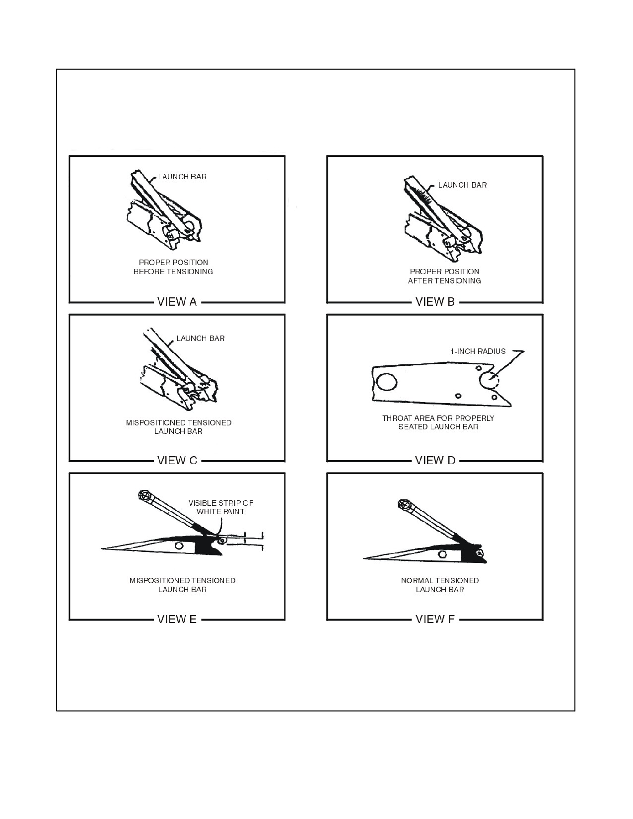
NAVAIR 00-80T-120
Figure 4-2. Proper Positioning After Tensioning
ORIGINAL
4-24

NAVAIR 00-80T-120
4. When all these conditions have been met and the Catapult Officer considers the aircraft and catapult ready for
launch, he shall accept control of the aircraft from the Director.
The Director shall not pass control of the aircraft until all personnel are clear
of the aircraft.
5. Once the Catapult Officer has control of the aircraft, he shall give the FINAL TURNUP signal.
6. The pilot, upon seeing the FINAL TURNUP signal, shall apply full military power as prescribed in the
applicable NATOPS flight manual. Pilots shall keep their feet off the brakes.
In the event of a suspend, the Catapult Officer shall not signal the pilot to
throttle back until he has positively determined that the catapult shuttle is
forward of the launch bar. If the launch bar cannot be raised without sending
personnel under the turned-up aircraft, an emergency condition exists. The
Catapult Officer shall positively determine that the catapult is in a SAFE
condition, then give pilot the THROTTLE BACK signal to permit safe
removal of the aircraft.
7. The Deckedge Operator, upon observing the FINAL TURNUP signal, immediately presses the
STANDBY/MIL PWR pushbutton.
a. As soon as the STANDBY/MIL PWR light comes on at the deckedge control panel, he holds two fingers
overhead.
Note
When catapults are being operated as interlocked pairs, the first catapult to
reach STANDBY/MIL PWR shall be fired or suspended before the other
catapult can attain STANDBY/MIL PWR.
8. For non-ICCS ships, the Console Operator, observing the STANDBY light on, immediately checks all gauges
and lights, and shall verify the position of the CSV by comparing the position readout on the console with the
mechanical counter on the CSV. If everything is satisfactory, he places the catapult in FINAL READY.
Silence shall be maintained on voice communication system from the time
the taking tension is passed until the launch has been completed, or if a
suspend or hangfire occurs, in order that signals between stations are not
misinterpreted.
4-25
ORIGINAL

NAVAIR 00-80T-120
9. For non-ICCS ships, when the catapult is in FINAL READY and the Deckedge Operator observed the
FINAL READY (red) light, he signals the catapult is in FINAL READY by raising both arms overhead
with hands open. This action also prevents him from inadvertently depressing the FIRE pushbutton.
The Deckedge Operator shall not lower his hands for any reason other than
to depress the FIRE or SUSPEND pushbutton.
10. For non-ICCS ships, if the launch is to be made at Combat Rated Thrust (CRT), the Catapult Officer, upon
observing that the catapult is in FINAL READY, shall give the CRT/AFTERBURNER signal.
11. For ICCS ships using Deckedge Mode, when the CCP Operator observes the military power light on, he shall
check all gauges and lights.
Silence shall be maintained on the voice communication system from the
time BRIDLE TENSION pushbutton is pressed until launch is completed
or a suspend/hangfire occurs.
12. For ICCS ships using Deckedge Mode, if CRT is required, the Catapult Officer gives the CRT signal.
a. The Deckedge Operator then shall press the combat power pushbutton.
13. For ICCS ships using Deckedge Mode, after the Catapult Officer salutes the pilot, the Deckedge Operator shall
depress the FINAL READY pushbutton.
a. After observing the final ready light, the Deckedge Operator shall give the final ready signal.
The Deckedge Operator shall not lower his hands for any reason other than
to depress the FIRE or SUSPEND pushbuttons.
14. The squadron Plane Checkers shall position themselves so they may observe the lighting of the afterburners
and normal nozzle action.
a. The Plane Checkers shall withhold giving the thumbs up (day) or steady vertical blue stubby wand (night)
signal until all conditions are normal.
b. Should an afterburner fail to ignite, the Plane Checker shall give the SUSPEND signal.
ORIGINAL
4-26

NAVAIR 00-80T-120
15. With the aircraft at take-off power, the pilot shall make his final checks. If everything is satisfactory, he shall
position his head against the seat headrest and shall indicate he is ready by turning his head slightly toward
the Catapult Officer and by executing a right- or left-hand salute.
a. If, for any reason, the pilot desires to abort the launch, he shall so indicate by transmitting “SUSPEND,
SUSPEND CATAPULT NO. ____,” and by shaking his head negatively (day) and not turning on the
navigation lights (night).
b. In such cases the Catapult Officer shall SUSPEND.
D Once the aircraft is tensioned on the catapult and turned up to take-off
power, the pilot shall not adjust his visor nor make any other movement that
might be mistaken for a salute until he is ready to be launched.
D The Air Officer shall not rely on changing rotating beacons from GREEN
to RED to suspend the launch, but shall activate the SUSPEND pushbutton.
16.
Upon receiving the pilot’s salute (day) or navigation lights on (night), but before giving the signal to FIRE,
the Catapult Officer shall return the salute (day) or extend a green wand overhead (night) and:
a. Check for a green rotating beacon.
b. Make a final scan of the aircraft.
c. Check the position of the flight controls.
d. Ensure the aircraft sounds normal at take-off power.
e. Ensure the catapult is still in final ready.
f. Check the Centerdeck Operator for a thumbs up (day) or steady white stubby wand (night) held vertically,
indicating wind is within limits.
g. Check squadron Plane Checkers for a thumbs up (day) or steady blue stubby wand (night) held vertically.
h. Check TSPO for a thumbs up (day) or steady white stubby wand (night) held vertically.
i. If the deck is pitching, the launch shall be timed and the fire signal given so that the deck will be level,
pitching up, or at the top of the pitch cycle at the completion of the catapult power stroke.
j. Check for airborne aircraft traffic (waveoff, bolter, etc.) to preclude the possibility of collision between the
airborne and the launching aircraft.
k. Check Bow/Angle Observer for GO signal.
Timing will vary with the cycle of the deck, and type of aircraft. Deckedge
Operators and pilots shall be briefed to not change procedures in an attempt
to time the shot themselves.
4-27
ORIGINAL

NAVAIR 00-80T-120
17. When the Catapult Officer determines the catapult, aircraft, and pilot are ready in every respect, he shall
give the signal to FIRE the catapult by sweeping his raised hand down in the direction of the launch,
touching the deck, and returning his hand to the horizontal position in the direction of launch.
D The Catapult Officer and all personnel in the vicinity of the launching
aircraft shall remain clear or in the crouched position and laterally clear
until the signaled aircraft has passed their position or until the Catapult
Officer has executed a SUSPEND/HANGFIRE and the catapult is safe.
D All personnel except centerdeck operator in the vicinity of launching
aircraft shall remain in a position prohibiting the aircraft wing from passing
over them during an aircraft launch.
18. The deck edge operator, upon observing the catapult officer touch the deck and returning his hand to the
horizontal position in the direction of the launch shall check the deck, aircraft, and catwalk (forward and aft)
noting the safeties (bow/angle) signal, thumbs up (day) or green wand/light (night), then lower hand and
depress the fire push button.
The Deckedge Operator shall not anticipate the FIRE signal, as the Catapult
Officer or topside personnel may initiate a SUSPEND at any time prior to
the Deckedge Operator depressing the FIRE pushbutton.
19. If any deficiency in aircraft hook-up is noted by the Deckedge Operator or if the deck and catwalk forward areas
are not clear, he shall not FIRE but SUSPEND and notify the Catapult Officer of the deficiency.
a. Anytime the Deckedge Operator suspends, he shall signal SUSPEND by crossing arms (day) or holding
red wand vertical overhead (night), to the Catapult Officer.
D The Catapult Officer, after touching the deck, shall monitor the pilot for any
signs of a SUSPEND. At night, he shall monitor the navigation lights
ensuring they remain on.
D It is extremely important that all personnel stationed in the catwalk remain
as low as possible and attempt to hug the inboard catwalk bulkhead when
the catapult is fired. This position will offer the most protection from the
jet blast and potential objects that may fall off the aircraft.
ORIGINAL
4-28

NAVAIR 00-80T-120
4.5.4 Launch Complete
During normal operations, never press the LAUNCH COMPLETE
pushbutton following a SUSPEND. Except for no-load launches and in
cases where it is known positively that a launch is complete, the LAUNCH
COMPLETE pushbutton shall be pressed only with permission of the
Catapult Officer.
1. After ensuring the launch is complete, the Console/CCP Operator shall prepare for the next launch.
a. The Deckedge Operator, after ensuring the track is clear, shall retract the shuttle.
2. Subsequent aircraft shall be spotted and tensioned as rapidly and safely as possible.
4.6
LAUNCHING AIRCRAFT (ICCS)
4.6.1 Taxiing/Spotting Aircraft on Catapults
1. When positioning an aircraft on the catapult, the Director shall be acutely aware of the activities of the catapult
crew, and shall control the aircraft’s speed and movement in such a way that personnel safety will not be
jeopardized.
a. Pilots shall guard against the tendency to use excessive power, which invariably results in roughness and
poor control and makes accurate catapult spotting difficult.
b. As the aircraft approaches the catapult, the Director shall signal the pilot to lower flaps.
c. Jet Blast Deflectors shall be raised as appropriate when the tail of the aircraft is clear.
D If a JBD cannot be raised, the Commanding Officer shall authorize the
catapult’s use.
D Personnel shall not work or transit immediately behind a JBD with aircraft
at launch power on the catapult.
CAUTION
Often aircraft on Catapult No. 4 block the view of the Catapult No. 3 JBD
Operator. All JBD Safety Observers/Operators shall ensure aircraft
clearance is sufficient prior to raising or lowering a JBD.
2. As the aircraft is positioned on the catapult, the squadron Plane Checkers shall inspect the aircraft to ensure
it is properly configured and ready for flight.
Under normal operating conditions, aircraft shall not be taxied to a position
where the launch bar can engage the spreader until the aircraft is ready for
flight in all respects. This includes gross weight confirmed, wings spread
and locked, flaps set, ordnance armed, green beacon, CSV set, and the
catapult in first ready/cat ready.
4-29
ORIGINAL

NAVAIR 00-80T-120
3. The Director shall stop the aircraft at the lead-in track wye area. He shall then signal the pilot to Disengage
Steering by touching the end of his nose with his forefinger and then sweeping his arm downward in the
direction of intended aircraft movement.
a. The Holdback Operator shall inspect the RRHB for proper reset indications prior to installation on each
aircraft.
b. The Holdback Operator shall install the holdback bar and check the tension bar/release unit for the proper
seating position (not cocked).
4. The Director shall then give the Lower Launch Bar signal to the pilot upon direction of the TSPO.
Holdback bars and/or release units should not be installed/lowered before
the aircraft reaches the lead-in wye area. Excessive wear or burring may
occur.
5. As the aircraft is taxied forward, the TSPO shall ensure the launch bar is properly positioned and that the buffer
slider is in its full aft position.
To avoid the possibility of premature tension bar failure, do not actuate
“BUFFER FWD” or “BUFFER AFT” pushbuttons during the aircraft
buffer stroke.
CAUTION
Aircraft taxi speed shall not exceed 4 mph while approaching the buffer.
6. Prior to taxiing aircraft over the shuttle (launch bar on top of shuttle), the TSPO shall re-verify positive reset
indication of RRHB. Positive RRHB reset is only established when the following conditions exist:
a. Strain release rod groove is completely visible.
b. Spring retainer groove is partially covered by housing.
c. Painted stripe area is completely covered from view.
Note
TSPO shall indicate to Catapult Shooter/Safety Observer that the RRHB
has been inspected by providing a thumb’s up signal during the day and
vertically raised white stubby wand at night.
7. The Director shall direct the pilot to taxi slowly over the shuttle spreader upon TSPO signal.
An incorrectly installed holdback bar can cause premature disengagement
during tensioning or when full thrust of the aircraft is applied.
ORIGINAL
4-30

NAVAIR 00-80T-120
4.6.2 Tensioning Aircraft
D When the Catapult Officer observes the aircraft type, weight, and side
number, he determines the capacity selector valve setting desired. He shall
relay this information to the CCP Operator for confirmation via the ICCS
monitor, who shall check the applicable Launching Bulletin. If the setting
desired by the Catapult Officer is correct, the CCP Operator shall press the
CSV setting pushbutton. If a mismatch occurs with the command setting
and any remote readout, the Catapult Officer/CCP Operator shall suspend
and down the catapult until the malfunction is corrected.
D Operation of the catapult in the defeat interlock mode shall be
accomplished only with the Commanding Officer’s permission. If the
defeat interlock mode is used, instructions delineated in the applicable
catapult operations manual
(NAVAIR 51-15 ABB Series) shall be
followed.
1. If the Monitor observes a red malfunction or status light, or the catapult area fouled, he shall press the suspend
pushbutton and notify the Catapult Officer.
2. The CCP Operator shall continually check his panels and ensure that all lights and readouts indicate a
“go” condition. If a “no-go” condition exists, he shall press the suspend pushbutton and notify the Monitor.
3. When all conditions are satisfactory prior to tensioning aircraft, the green CAT RDY light at the Catapult
Officer’s Console and white lights at the CCP and Monitor’s station shall be illuminated. If the CAT RDY
lights are not illuminated, the cause shall be investigated and corrected.
If the cat ready condition is lost even momentarily, the catapult officer,
monitor or CCP operator shall suspend the catapult and determine the
cause. When the condition causing the loss of cat ready has been corrected,
the suspend shall be removed. At no time shall the catapult officer place the
catapult in tension without first reconfirming the CSV setting and ensuring
a cat ready condition exists.
4. Prior to signaling the Catapult Safety Observer to initiate the hook-up, the Catapult Officer shall ensure:
a. The CSV is set in accordance with the appropriate launching bulletin.
b. Check for a clear deck forward.
c. Wind over the deck and crosswinds are within limits and in accordance with applicable launch bulletins.
d. Green rotating beacon.
e. In CAT RDY.
f. Aircraft configured for flight.
g. The “catapults interlocked” light is illuminated unless intentionally operating in the “catapults not
interlocked” mode.
4-31
ORIGINAL

NAVAIR 00-80T-120
h. GO/NO GO charts are reviewed.
i. When all conditions are satisfactory, the Catapult Officer shall signal the Catapult Safety Observer to hook
up the aircraft.
Note
For Case III launches, the Catapult Officer shall maintain absolute control
of the launch sequence, and aircraft shall not be tensioned except upon the
Catapult Officer’s signal.
5.
After receiving the hook-up signal from the Catapult Officer, and prior to signaling the TSPO to initiate
hook-up, the Catapult Safety Observer shall ensure that:
a. Check for a clear deck forward.
b. JBDs are raised and aircraft immediately aft of the JBD are configured to sustain turbulence from launching
aircraft.
c. Aircraft is properly configured for flight.
d. Aircraft is properly armed (if applicable).
e. Green rotating beacon.
f. The TSPO is giving thumbs up (day) or steady white stubby wand (night) indicating ready for hook-up.
6.
When all conditions are satisfactory, the Catapult Safety Observer shall give the hook-up signal to the TSPO.
7.
When the TSPO receives the hook-up signal from the Catapult Safety Observer, he shall ensure the following
prior to signaling tension:
a. In case of nose gear launch aircraft, ensure the holdback is properly seated in the buffer hooks and the aircraft
has fully engaged the nose gear launch unit.
b. JBDs are raised and personnel properly positioned.
c. Check for a clear deck forward.
d. Squadron Plane Checkers are clear from under the aircraft.
e. Catapult deckedge red suspend light not illuminated.
Aircraft tiedown rings shall not be used as handles while placing an aircraft
in tension.
8. The TSPO shall then give the tension signal by sweeping one arm and pointing forefinger (day), white stubby
flashlight (night), in forward direction of launch to the Catapult Safety Observer and Director and held until
tension is taken.
9. After receiving the tension signal from the TSPO, the Director shall:
a. Check forward and aft ensuring all personnel (director included) in the vicinity of the launching aircraft are
laterally clear and aircraft are clear of the catapult “safe shot line.”
b. Ensure JBDs are raised and personnel properly positioned.
ORIGINAL
4-32

NAVAIR 00-80T-120
c. Signal the pilot to release brakes followed by the tension signal.
d. Once TSPO has exited, pass control of the aircraft to the Catapult Safety Observer.
10. After receiving the tension signal from the Director, the Catapult Officer shall depress the tension pushbutton,
paying particular attention to proper engagement of the shuttle and launch bar, as the shuttle strokes forward.
After tension is taken, the TSPO shall perform the following:
a. For nose tow aircraft: After tension is taken, the TSPO shall inspect the seating of the launch bar in the
spreader, and inspect the seating of the tension bar/repeatable release element prior to exiting from under
the aircraft. Give the Catapult Safety Observer a thumbs up (day) or steady white stubby wand (night) held
vertically if all conditions are satisfactory.
It is mandatory that it be positively determined that the aircraft launch bar
is properly seated in the nose gear launch shuttle spreader as shown in
Figure 4-2 after tension is taken. Mispositioning of the aircraft launch bar
can result in the launch bar prematurely separating from the shuttle spreader
during the launch. F/A-18 aircraft shall not be launched with improper or
missing launch bar paint schemes.
11. Before tensioning, the CCP Operator shall verify the position of the CSV by comparing the digital readout
on the CCP with the mechanical counter on the CSV.
a. After ensuring both readouts match, the CCP Operator shall repeat the CSV settings to the Monitor over
the voice communication system.
b. The Monitor shall advise the Catapult Officer of the CSV setting.
12. The CCP Operator shall verify the Catapult Officer’s CSV setting by referring to the appropriate launch chart,
and the wind indicator. If the CCP Operator disagrees with the CSV setting selected by the Catapult Officer,
he shall suspend.
Independent computations of CSV settings by CCP Operators cross-check
CSV settings by Catapult Officers; therefore, it is essential that CCP
Operators be fully trained on launch bulletin usage and CSV computation.
4.6.3 Launch
1. After observing the TSPO exiting from under the aircraft, giving a thumbs-up (day) or steady white stubby
wand (night) signal, the Catapult Officer shall depress the military power pushbutton and, if applicable, the
combat power pushbutton.
2. The pilot shall apply full take-off power and, if applicable, afterburner when the deck signal lights are
illuminated and/or after Catapult Safety Observer’s signal.
4-33
ORIGINAL

NAVAIR 00-80T-120
Note
The military and combat power deck lights are located on the ICCS for
catapults No. 1, 3 and 4. The military and combat power deck lights for
catapult No. 2 are located on the forward deck edge left of the battery
position. The two lights are installed such that the light beam from each
light can be seen by the pilot of the aircraft being launched. The green
military power light is continuously on during military power and the
combat power light (amber) is continuously on during combat power.
When the catapult’s final ready is reached, the military and combat power
lights both flash.
3. The squadron Plane Checkers shall position themselves so they may observe the lighting of the afterburners
and normal nozzle action. They shall withhold giving the thumbs-up (day) or steady blue stubby wand (night)
signal until all conditions are normal. Should an afterburner fail to ignite, the Plane Checker shall give the
SUSPEND signal.
4. With the aircraft at take-off power, the pilot shall make his final checks. If everything is satisfactory, he shall
position his head against the seat headrest and shall indicate he is ready by turning his head slightly toward
the Catapult Safety Observer and by executing a right- or left-hand salute.
a. If, for any reason, the pilot desires to abort the launch, he shall so indicate by transmitting “SUSPEND,
SUSPEND CATAPULT NO.____,” and by shaking his head negatively (day) and not turning on the
navigation lights (night), in which case the Catapult Officer shall SUSPEND.
D Once the aircraft is tensioned on the catapult and turned up to take-off
power, the pilot shall not adjust his visor nor make any other movement that
might be mistaken for a salute until he is ready to be launched.
D The Air Officer shall not rely on changing rotating beacons from GREEN
to RED to suspend the launch, but shall activate the SUSPEND pushbutton.
D If there is any doubt in the mind of the Catapult Safety Observer, TSPO,
Director, Plane Checker, or any topside crewman as to satisfactory hookup,
aircraft configuration, or proper catapult condition, he shall give the
SUSPEND signal — crossed arms overhead (day) or horizontal wand
movement (night). Below deck personnel shall depress their SUSPEND
buttons and/or state “SUSPEND” over the voice communication system.
5.
The Catapult Safety Observer, after observing the pilot’s salute (day) or navigation lights (night), shall return
the salute (day) and shall:
a. Immediately assume a crouched position, and ensure all personnel in the immediate catapult area are in a
crouched position.
b. Ensure the aircraft is properly configured for flight, paying particular attention to flap/slat setting, open
panels, safety pins, wing locks, and stabilizer position.
c. Check for a green rotating beacon.
d. Check for a clear deck forward.
e. Ensure the catapult deckedge red suspend light is not illuminated.
f. Ensure the aircraft sounds normal at take-off power.
ORIGINAL
4-34

NAVAIR 00-80T-120
g. Check squadron Plane Checkers for thumbs up (day) or steady blue stubby wand (night) held vertically.
h. Check TSPO for a thumbs up (day) or steady white stubby wand (night) held vertically.
i. Ensure Bow/Angle Safety Observers are displaying green light/thumbs up (day) or green light/wand
(night).
j. Check for airborne aircraft traffic (wave-off, bolter, etc.) to preclude the possibility of collision between
the airborne and the launching aircraft.
6. If all conditions are satisfactory, the Catapult Safety Observer shall go down on one knee and give a thumbs
up (day) or vertical green wand (night) to the Catapult Officer.
7. The Catapult Officer, upon observing the pilot’s salute (day) or navigation lights illuminated (night) and the
Catapult Safety Observer in a crouched position, shall depress the final ready pushbutton and begin a final scan.
(ICCS; all modes of operation.) If at any time after launch bar is in the
spreader there is a need to make a CSV setting change, the catapult shall
be suspended and launch bar raised. The verification process shall be
completed again. Any time there is a disagreement between any stations on
the correct CSV setting, the catapult shall be suspended until resolution of
the disagreement.
8.
The CCP Operator, after observing the final ready light illuminated, shall conduct a final scan of the CCP,
paying particular attention to ensure the launch valve clock timers have reset to zero. If there is an indication
of any malfunction, the CCP Operator shall immediately suspend the catapult.
9.
The Monitor, after observing the final ready light illuminated, shall conduct a final scan of his control console,
checking for malfunction lights or red status lights, and shall announce to the Catapult Officer the steam
pressure and “CLEAR FORWARD.” If there is any indication of a malfunction, the catapult shall immediately
be suspended.
10.
If all conditions are “go,” the Catapult Officer shall complete his final scan and shall include the following:
a. Check for a clear deck forward.
b. Monitor’s console for malfunction indications.
c. Green rotating beacon/green “GO” light on Catapult Officer’s console.
d. Green steam pressure “GO” light on Catapult Officer’s console.
e. Wind and crosswind components.
f. Verify green CSV match light.
g. Observe Catapult Safety Observer, TSPO, and squadron Plane Checkers giving thumbs up or appropriate
night signal.
h. Observe aircraft properly configured for flight.
i. Observe pilot is properly positioned for launch.
j. Check deck pitch.
11.
If all conditions are satisfactory, the Catapult Officer shall depress the fire pushbutton.
4-35
ORIGINAL

NAVAIR 00-80T-120
4.6.4 Launch Complete
During normal operations, never press the LAUNCH COMPLETE
pushbutton following a SUSPEND. Except for no-load launches and in
cases where it is known positively that a launch is complete, the LAUNCH
COMPLETE pushbutton shall be pressed only with the permission of the
Catapult Officer.
1.
After ensuring the launch is complete, the CCP shall take such actions as necessary to initiate the next launch.
2.
The Monitor Operator shall retract the shuttle after ensuring the track is clear.
3.
Subsequent aircraft shall be spotted and tensioned as rapidly and safely as possible.
4.7
NIGHT/CASE III OPERATIONS
1.
Night/Case III procedures are essentially the same as those for normal day operations with one exception; a
minimum departure (launch) interval of 30 seconds shall be utilized between aircraft.
2.
The Catapult Officers shall have sufficient view of the other set of catapults so that they may control the launch
interval or the Air Officer may maintain complete control. In any case, the Air Officer shall monitor the launch
to ensure that the bow and waist catapults do not launch simultaneously, and provide coordinating assistance
should any unusual circumstances, such as aircraft or catapult becoming inoperative, arise.
3.
The types of wands to be used during launching operations are as follows:
Catapult Officer/ Catapult Safety Observer
1 red and 1 green standard
Topside Petty Officer
1 white stubby
Director
2 amber standard
Plane Checker
1 blue stubby
Centerdeck Operator
1 white stubby
Deckedge Operator
1 red standard
Ordnance Safety
2 red standard (banded)
JBD Safety
1 white stubby
Bow/Angle Safety Observer
1 red and 1 green standard
Weight Board
1 white stubby
Note
The Centerdeck Operator shall maintain an extra set of Catapult Officer’s
wands. Standard denotes full length cones and stubby denotes a modified
cone providing 3 inches of cone. Any suitable battery and switch housing
are authorized if the cone is brightly lighted. Banded denotes two 3/4-inch
bands spaced equidistant from the cone.
4.8
DECK LAUNCHING
1.
If a deck launch is preceded by a catapult launch, it is the responsibility of the Catapult Launching Officer to
ensure that all personnel and equipment are clear, and that no loose gear is adrift on the deck area to be used
ORIGINAL
4-36

NAVAIR 00-80T-120
(axial/angle). The Catapult Launching Officer shall then give the Deck Launching Officer the “CLEAR
DECK” signal.
a. The Air Officer shall announce on the 5MC “STAND CLEAR OF THE ANGLE/BOW WHILE DECK
LAUNCHING AIRCRAFT.”
b. The Air Officer shall not turn the rotating beacon from red to green until the warning is given.
2.
When a deck launch is not preceded by a catapult launch, it is the responsibility of the Deck Launching Officer
to ensure all the aforementioned are accomplished prior to launch.
3.
Before clearing the Launching Officer to commence launching aircraft, the Air Officer shall verify the
previously determined deck run required.
a. The Director, when positioning the aircraft for launch, shall ensure that the nose wheel is aligned, wings
are spread and locked, and flaps are set as required before passing control to the Launching Officer. The
aircraft shall be aligned as accurately as possible with the launch lineup line (landing area centerline when
launching down the angle deck).
b. The Director shall then taxi the aircraft into position, and the squadron’s aircraft inspector shall check the
aircraft for loose or missing panels/doors, leaks, and other visible discrepancies. If he is satisfied and the
aircraft is ready for launch, he shall so signify by giving the Launching Officer the “THUMBS UP” signal.
4.
The Launching Officer shall:
a. Ensure the area behind the aircraft is clear of personnel, equipment, and loose gear.
b. Check for a green rotating beacon and a clear deck forward before signaling for the pilot to add power for
takeoff.
5.
When signaled to do so, the pilot shall smoothly but expeditiously add power and complete final cockpit
checks. He shall, in the case of a single-piloted aircraft, indicate his readiness for launch by an exaggerated
nod of the head in the daytime or by turning navigation lights on steady at night. In dual-piloted aircraft,
readiness to launch shall be signaled by a salute from the pilot, relayed by the copilot if the Launching Officer
is on the starboard side of the aircraft.
6.
As power is being applied for launch, the Launching Officer shall check the aircraft’s configuration and inspect
it for leaks or other visible discrepancies. After receiving a “THUMBS UP” from the aircraft inspector and
a salute from the pilot(s), the Launching Officer shall again check for a clear deck forward. He shall ensure
that the deck and catwalks are clear of personnel before giving the pilot the signal to launch.
7.
After receiving the launch signal, the pilot shall release his brakes and execute a takeoff in accordance with
the applicable aircraft NATOPS flight manual.
4.9
CARRIER QUALIFICATIONS
During CARQUAL operations, the pilot shall transmit aircraft side number, fuel weight, and gross weight during
a two-way radio check. The same transmission is required not only for the initial launch but also after hot refueling
and after a pilot switch. The Air Officer shall ensure that the aircraft side number and gross weight are passed to the
Catapult Officer.
D The Launching Officer shall closely scan recovering aircraft to avoid
simultaneously launching and recovering aircraft.
D During CARQUAL operations, a close monitoring of aircraft gross weights
is mandatory by the Air Officer, the Catapult Officer, pilots, and squadron
representatives.
4-37
ORIGINAL

NAVAIR 00-80T-120
4.10
POST-LAUNCH PROCEDURES
4.10.1 Pilot Debrief
It is extremely important to maintain a flow of information between the pilots and the Catapult Officers. When pilots
make procedural errors, they should be aware of their errors so a complete understanding of flight deck procedures
is maintained. Catapult Officers shall keep in mind that each pilot is an individual and each has his own level of
proficiency. At times, the Catapult Officer shall become an instructor of flight deck procedures. Everyone connected
with the launch should know what everyone else is doing and the reason why. The predeployment brief and
post-launch debriefs are necessary to ensure the pilots do know what is going on around them and to correct any
misunderstanding they might have about procedures and the functions of flight deck personnel.
Some of the common errors that should be covered in debriefs are:
1. Reducing power on a SUSPEND signal rather than waiting for a THROTTLE BACK signal from the Catapult
Officer/Catapult Safety Observer.
2. Not recognizing other than normal night signals; in particular, THROTTLE BACK signal at night.
3. Raising a hand to his head to adjust visor, set clock, or make actions that might be misinterpreted as a salute
while in tension and at full power.
4. Not understanding the weight board procedures, using improper signals when trying to lower or raise weight,
and/or not having a flashlight at night to give the proper signals (this goes for RIOs, BNs, and other crewmen
as well).
5. Not knowing the weight of the aircraft prior to arriving at the catapult.
6. Not completing his take-off list (checklists, under normal circumstances, shall be completed prior to crossing
the shuttle).
7. Saluting before the Catapult Officer/Catapult Safety Observer has control of the aircraft (although not unsafe,
does lead to confusion between pilot and Catapult Officer).
8. Rough or rapid taxi procedures.
4.10.2 Catapult Crew Debrief
While not always necessary or required after every launch, post-launch debriefs by the Catapult Officer should be
held with the catapult crews periodically, and shall be held whenever a situation during a launch needs clarification.
These debriefs may pertain to the topside crew, the below deck crew, or the entire catapult crew.
The best possible results may be realized when there is a continuing flow of information and ideas among the Catapult
Officer, supervisory personnel, and the catapult crew. Debriefs that correct errors and compliment the crew on
outstanding performance can do wonders for crew morale and enhance the smoothness and efficiency of subsequent
launches.
4.10.3 Shot Log Review
After each day’s operations, the ALRE Maintenance Officer shall review the shot log. The catapult will rarely fail
without giving fair warning. By reviewing the shot log daily, the ALRE Maintenance Officer may be able to detect
a possible malfunction before it occurs. Items to be checked and compared include:
1. Launch valve timer readings.
2. End-speeds above and below predicted (excess).
3. Steam temperatures and pressures (before and after shot).
Note
Upon completion of each cycle launch, the Catapult Officer shall review
shot logs.
ORIGINAL
4-38

NAVAIR 00-80T-120
4.11
EMERGENCY ACTIONS AND PROCEDURES
Safety is paramount when conducting emergency procedures. Proper procedures coupled with common sense will
enable catapult crews to handle any emergency. This manual does not discuss all emergencies, nor are they in-depth.
The reader should refer to appropriate NAVAIR Operation Manuals for a thorough discussion of emergency procedures.
Drill scenarios and periodicity requirements are outlined in Appendix II of COMNAVAIRFORINST 3500.20 series.
4.11.1 Aborting the Launch
1.
At any time, up to and including FINAL READY, firing of the catapult can be prevented and the launch
aborted. The Deckedge Operator, Console/CCP Operator, Monitor, PriFly, Water Brake Operator, and
Catapult Officer (ICCS) all have SUSPEND switches, which when activated, break the interlock complete
circuit and prevent the launch.
2.
Any person, other than those having access to a SUSPEND switch, who detects a cause for aborting the launch
shall signal the Catapult Officer/Catapult Safety Observer and/or the Deckedge Operator/Monitor by crossing
his arms high overhead (day) or waving a wand back and forth horizontally (night) to indicate a SUSPEND
situation exists.
3.
The Deckedge/Monitor Operator does not have to receive the SUSPEND signal from the Catapult
Officer/Catapult Safety Observer in order to actuate his SUSPEND switch. He shall do so immediately upon
observing a SUSPEND signal from anyone on deck, or if he detects any condition that would be reason to abort
the launch.
4.
The pilot can abort the launch at any time prior to being tensioned by refusing to taxi onto the catapult, and/or
using hand signals to indicate his desire not to go. At night, he shall notify PriFly who shall relay his problems
to the Catapult Officer/Director.
5.
Once the aircraft is tensioned, the pilot shall indicate his desire to abort by shaking his head negatively (day)
and by not turning on his lights (night), and by transmitting the words “SUSPEND, SUSPEND, CATAPULT
NO.______.” The Catapult Officer, after taking control of the aircraft and upon observing the aircraft turning
up to full power, shall wait a reasonable length of time and then initiate a SUSPEND if PriFly has not already
done so.
6.
Any time a SUSPEND is initiated, it shall be carried out to completion. This includes untensioning of the
aircraft, reduction of aircraft power back to idle, and moving the shuttle forward of the launch bar; it does not
necessarily include removal of the aircraft from the catapult.
In the event of a SUSPEND, the Catapult Officer/Catapult Safety Observer
shall not signal the pilot to throttle back until he has positively determined
that the catapult is safe/suspended and the shuttle is forward of the launch
bar. If the launch bar cannot be raised without sending personnel under the
aircraft, the Catapult Officer shall ensure the catapult is safe/suspended,
then give pilot the THROTTLE BACK signal. With direct control of the
aircraft, the Catapult Officer shall then send personnel to lift the launch bar
and signal SHUTTLE FORWARD with caution.
4.11.2 SUSPEND (Conventional/Deckedge Mode)
4.11.2.1 Signals and Procedures
1. Any time prior to the FIRE pushbutton being depressed, the catapult may be stopped and the launch aborted,
by initiating a catapult SUSPEND. The Catapult Officer, upon observing a SUSPEND condition or being
notified of a catapult SUSPEND situation, shall give the SUSPEND signal.
4-39
ORIGINAL

NAVAIR 00-80T-120
Any flight deck crewman who detects any reason for aborting the launch may suspend the catapult launch by
immediately giving the SUSPEND signal.
2. Any time a SUSPEND is initiated, it shall be carried out to completion. This includes untensioning of the
aircraft, moving the shuttle forward of the launch bar, and reducing the aircraft power to idle.
3. The Deckedge Operator, upon observing any SUSPEND signal, shall immediately actuate the SUSPEND
switch followed by giving the SUSPEND signal.
When the SUSPEND signal is given, the pilot shall remain ready to be
launched, and he shall not retard his throttle until so directed by the Catapult
Officer. At no time after full power turn-up shall the signal to retard throttle
be given to the pilot until the catapult is SAFE.
Note
In the event another station suspends the catapult, the Deckedge Operator
shall give the SUSPEND signal to notify the Catapult Officer of the
SUSPEND condition.
4.
The Catapult Officer, after noting the return of his SUSPEND signal, shall signal the Deckedge Operator to
UNTENSION (SHUTTLE AFT) the aircraft.
5.
The Deckedge Operator shall immediately depress shuttle/maneuver aft causing tension to be relaxed and the
shuttle to move aft.
6.
If the Water Brake Operator initiated the SUSPEND, the Console/CCP Operator shall actuate his suspend
switch and then direct the Water Brake Operator to remove his SUSPEND prior to the Deckedge/Monitor
Operator depressing the maneuver aft pushbutton.
a. In case of electrical failure, the Deckedge Operator shall direct the Retraction Engine Operator to depress
the manual override on the maneuvering valve.
7.
As the shuttle moves aft, the launch bar normally will raise automatically as it disengages the throat of the
shuttle. With the launch bar in the raised position, the Catapult Officer shall give the SHUTTLE FORWARD
signal to the Deckedge Operator.
8.
Once the shuttle is forward of the launch bar, the Catapult Officer shall give the THROTTLE BACK signal
to the pilot.
D Catapult crewmen shall not approach the aircraft until the shuttle is forward
of the launch bar, and the pilot has retarded his throttle to idle, except when
an emergency condition exists.
D In the event of a SUSPEND, the Catapult Officer shall not signal the pilot
to throttle back until he has positively determined that the catapult is
suspended and the shuttle is forward of the launch bar. If the launch bar
cannot be raised without sending personnel under the aircraft, the Catapult
Officer shall ensure the catapult is suspended and then give the
THROTTLE BACK signal. With direct control of the aircraft, the Catapult
Officer shall then send personnel to lift the launch bar and signal
SHUTTLE FORWARD with caution.
ORIGINAL
4-40

NAVAIR 00-80T-120
Note
If failure of the bridle tensioner prevents normal movement of the shuttle
past the raised launch bar, the Catapult Officer shall throttle back the
aircraft, and instruct applicable watch stations to position their SUSPEND
switches off, and instruct the Deckedge Operator to MANEUVER
FORWARD. After the shuttle is maneuvered forward, the SUSPEND
switches shall be reactivated, if applicable.
9. When the catapult is safe, the cause of the SUSPEND shall be determined prior to resuming catapult
operations.
10. With the aircraft at idle power, control shall be passed to the Director to either resume the launch, or to remove
the aircraft from the catapult.
4.11.2.2 Procedures Under Emergency Conditions
Note
Emergency conditions are construed to apply to aircraft that do not have the
capability to, or are unable to, raise the launch bar automatically.
1. If the shuttle is moved aft and the launch bar does not automatically raise, the Catapult Officer, after ensuring
the catapult is properly suspended, shall signal the pilot to THROTTLE BACK.
a. When the aircraft is at idle power, the launch bar shall be raised manually by the TSPO and held until the
shuttle is moved forward of the launch bar.
The TSPO, holding the launch bar in the raised position, shall keep hands
clear of the shuttle as it is maneuvered forward. In the event the launch bar
begins to slip, any attempt by the TSPO to recover the launch bar may result
in serious injury. Ensure both hands are clear of the shuttle and visible to
the Catapult Officer and Deck Edge Operator prior to reattempting to raise
the launch bar.
2. For nose tow aircraft, if the grab latch fails or any malfunction preventing the shuttle to
SHUTTLE/MANEUVER AFT, the Catapult Officer, after ensuring the catapult is safe/suspended, may:
a. Throttle back the aircraft.
b. Off brakes.
c. Buffer aft for 4 to 10 inches.
d. Taxi aircraft forward.
e. Raise launch bar.
f. Shuttle forward.
CAUTION
Do not allow the NGL unit to buffer too far aft causing buffer hook
retraction with the trail bar still attached.
4-41
ORIGINAL

NAVAIR 00-80T-120
4.11.2.3 Removing Aircraft from Catapults
1. Prior to buffering aft, ensure the aircraft is de-armed and the JBD is lowered.
CAUTION
Reverse taxi of an E2/C2 to relieve tension on the trail bar may result in
damage to the catapult and/or aircraft.
Note
In the event BUFFER AFT is inoperative, E2/C2 aircraft shall be shutdown
and a tractor and tow bar utilized to relieve trail bar tension.
2.
Once the shuttle is forward, the control is passed to the Director.
3.
In order to remove the aircraft from the buffer unit when buffering aft, the Director, upon a signal from the
Catapult Officer, shall signal OFF BRAKES.
a. The Catapult Officer shall then signal the Deckedge Operator to BUFFER AFT by holding both arms at
waist level and pointing forefingers (day), wands (night), in the aft direction.
4.
After the aircraft moves approximately 4 to 10 inches, the Catapult Officer signals the pilot via the Director
to HOLD BRAKES.
5.
The Catapult Officer shall then give the BUFFER FWD signal by holding both arms at waist level and pointing
forefingers (day), wands (night) in the forward direction to the Deckedge Operator who presses the
BUFFER FWD pushbutton to allow slack in the holdback bar/release element.
a. The catapult crew then may disconnect the holdback bar/release element.
b. After the holdback bar/release element is removed, the Catapult Officer signals the Deckedge Operator to
BUFFER AFT to lower the buffer hooks.
c. When the catapult crew is clear, the Catapult Officer passes control back to the Director, and then the aircraft
may be taxied/towed forward and clear of the catapult.
6.
The hand signal sequence required to complete removing an aircraft is as presented in Figure 4-3.
4.11.3 SUSPEND (ICCS)
4.11.3.1 Signals and Procedures
1. Any time prior to the FIRE pushbutton being depressed, the launch may be aborted by initiating a catapult
SUSPEND. The Catapult Officer, upon observing a SUSPEND condition or being notified of a catapult
SUSPEND situation, shall initiate the SUSPEND procedure by immediately depressing the catapult
SUSPEND pushbutton. Any flight deck crewman who detects any reason for aborting the launch may suspend
the catapult launch by immediately giving the SUSPEND signal.
2. Any time a SUSPEND is initiated, it shall be carried out to completion. This includes untensioning of the
aircraft, reduction of aircraft power to idle, and moving the shuttle forward of the launch bar.
3. The Catapult Safety Observer shall, upon observing a SUSPEND signal, or the flashing red deckedge
SUSPEND light, give the SUSPEND signal immediately followed by the SHUTTLE AFT/UNTENSION
signal.
4. Upon observing the SHUTTLE AFT/UNTENSION signal, the Catapult Officer shall depress the
MANEUVER AFT pushbutton.
ORIGINAL
4-42

NAVAIR 00-80T-120
NOSETOW
(T-45, S-3, F/A-18)
NOSETOW (EA-6B, E-2, C-2)
Suspend
Suspend
Shuttle Aft/Untension
Shuttle Aft/Untension
Raise Launch Bar2
Throttle Back
Shuttle Forward
Raise Launch Bar
Throttle Back
Off Brakes
When raising launch bar by hand, exercise
extreme care to avoid hand injuries.
Buffer Aft
Shuttle Forward
Hold Brakes
Off Brakes
Buffer Forward
Buffer Aft3
Buffer Aft
Hold Brakes
Pass Control1
Buffer Forward
Buffer Aft
Pass Control1
NOTES:
1 The Director shall taxi the aircraft clear of the NGL guide track after the holdback bar/release element has
been removed.
2 If the launch bar does not raise automatically, the catapult shall be properly suspended and the throttle re-
tarded so the TSPO can raise and hold the launch bar up until the shuttle is maneuvered forward of the
launch bar. The launch bar shall be lowered for the buffer sequence.
3 Buffering aft of E-2/C-2/EA-6B aircraft with the launch bar in the locked-up position will damage the aircraft
nose gear assembly.
Figure 4-3. Hand Signal Sequence for Aircraft Removal
4-43
ORIGINAL
//////////////////////////////////////////