NAVAIR 00-80R-14-1 NATOPS U.S. NAVY AIRCRAFT EMERGENCY RESCUE INFORMATION MANUAL (2009) - page 3
2.
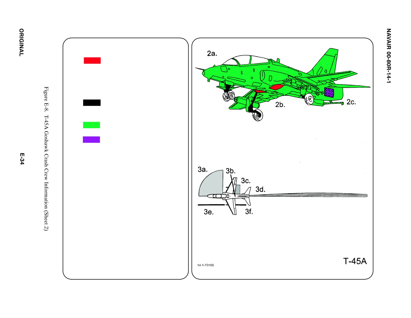
AIRFRAME MATERIALS
a. Graphite Epoxy
ąMLG Inboard Doors
ąSlat Control Rods
ą(Inside Wing Leading Edge)
b. N/A
c. Steel
d. N/A
e. Aluminum
f. Carbon Epoxy
g. N/A
3.
AIRCRAFT DANGER AREAS
a. Intake Area
ąMRT — 20 feet
ąIdle — 5 feet
b. GTS Exhaust (top)
c. Turbine Failure
ąOutboard between wing and stabilator
d. Engine Exhaust
ąIdle — 40 feet
ąMRT — 100 feet
e. Rocket wd Fire Zone (2 places)
f. Rocket Exhaust Zone (2 places)
4.
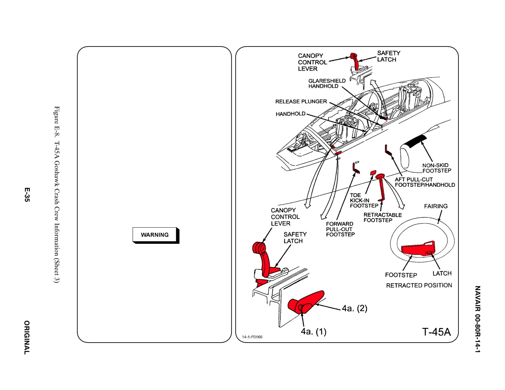
AIRCRAFT ENTRY
a.
NORMAL ENTRY
Access to cockpit in normal operation is
gained by using the side opening canopy's
external handle. A retractable footstep, toe
kick-in footstep, two pullout
footsteps/handholds, a nonskid footstep,
and two handholds are available for
forward and aft cockpit entry.
(1) PRESS Canopy External Handle
release button.
(2) ROTATE Canopy External Handle
CLOCKWISE and LIFT canopy.
b. N/A
c.
EMERGENCY ENTRY
Access to the cockpit can be gained in
emergency situations by manually opening
canopy external handle; however, if this
proves impossible, canopy can be
shattered by aircrew operation of mild
detonating cords (MDC). 123
D The canopy pyrotechnic
(MDC)
should not be used if flammable
liquids or fumes are present in area.
D Particles from a blown canopy may
exceed 3 square inches and cover a
blast radius area of over 25 feet.
4. AIRCRAFT ENTRY (CONT.) abc
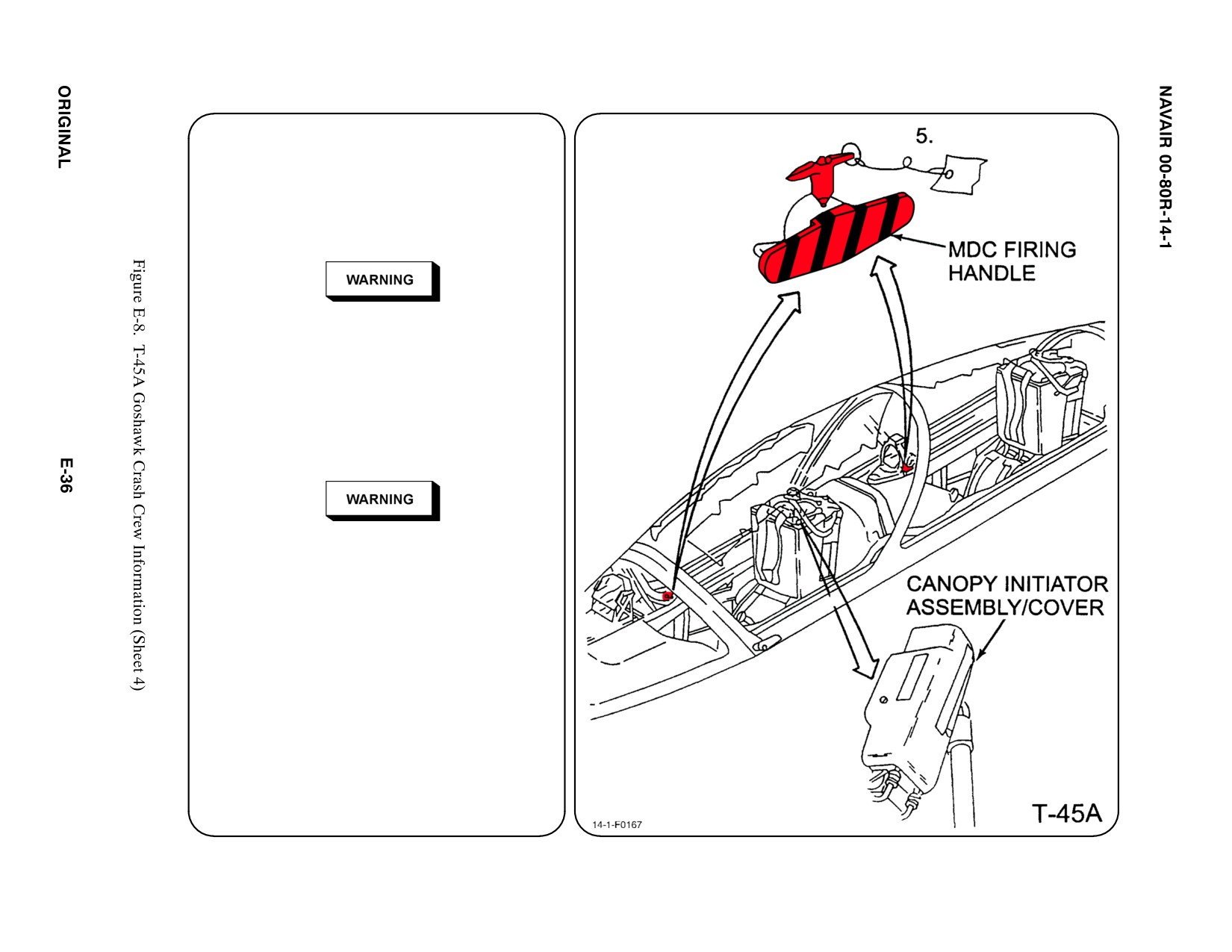
d. FORCED ENTRY
Canopy is acrylic plastic and may be cut
with power rescue saw or shattered by
impact with crash axe. Cut along canopy
frame.
Do not cut into canopy SMDC initiator
assembly on the right side of canopy.
This could detonate the canopy
fracturing pyrotechnics.
5. CANOPY SAFETY PROCEDURES
Remove streamers and safety pins from map
case containers and install in MDC firing
handle (both cockpits).
With safety pins installed, canopy
initiators can still be ignited by
stepping on or leaning on Initiator
Assembly or cover.
a. N/A
b. N/A
6.
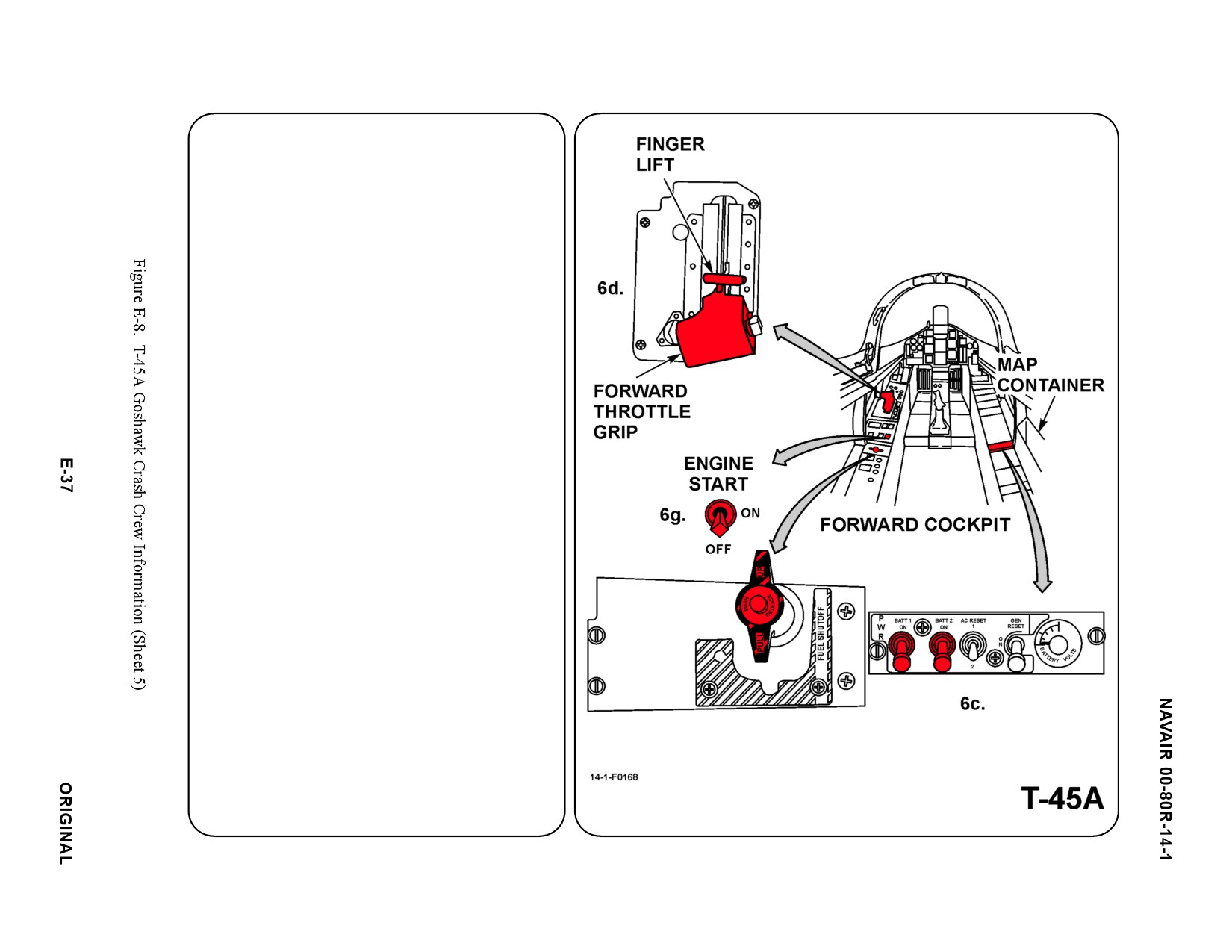
ENGINE/GTS SHUTDOWN
a. N/A
b. N/A
c. BATTERY SWITCHES
PLACE BATT 1 and BATT 2 switches in
OFF position
d. THROTTLE
MOVE throttle AFT to stop, then RAISE
finger lift and MOVE throttle AFT to OFF
position (either cockpit).
e. FUEL SHUTOFF
PRESS release button on top of Fuel
Shutoff Handle and PULL handle up (front
cockpit only).
f. N/A
g. GTS
PLACE the Engine Start Switch in OFF
position (both cockpits).
7.
N/A
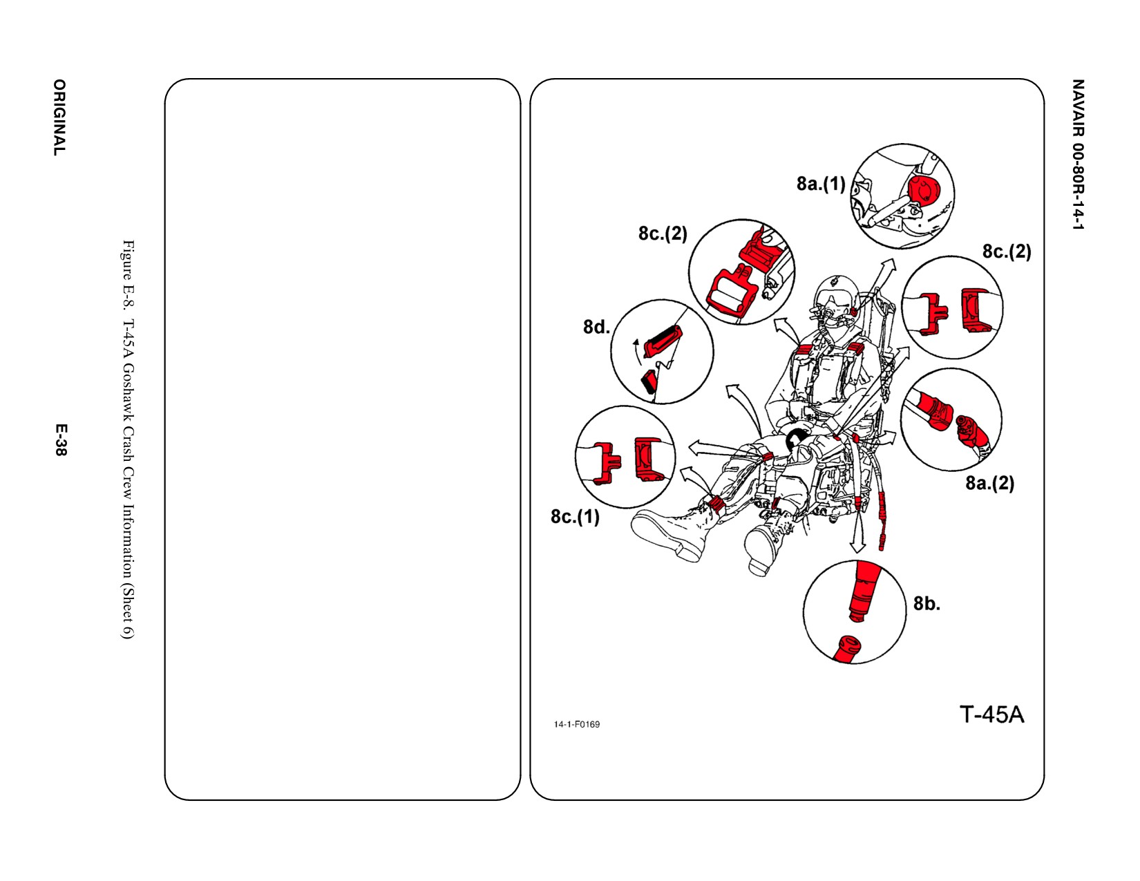
8.
CREW RELEASE
Each crewmember is attached to the seat by
the use of an integrated harness and leg
restraints. Additionally, the
oxygen/communication lead is attached to
survival kit. If crewmember is wearing an
anti-G suit a hose will be attached to an outlet
on left console.
a.
PERSONAL SERVICE, QUICK
DISCONNECT
(1) Remove oxygen mask by pulling down
on the release tabs on either side of
mask.
(2) Disconnect oxygen/communication
lead at survival kit. Grasp knurled fitting
on hose and pull up to disconnect.
b. RESTRAINT SUIT BELTS/RELEASE
Pull anti-G suit hose from left console.
c.
HARNESS STRAPS/LEG RESTRAINT
RELEASE
(1) Leg garter is secured around leg by a
quick disconnect. Leg restraints lines
attach to garter using the same types
of quick disconnect.
(2) Support pilot, release two (2) lap belts,
than two (2) shoulder harness Koch
fittings or cut webbing and remove pilot
from cockpit.
d. EMERGENCY RELEASE
(1) Press thumb button on Emergency
restraint release handle (right side of
seat) and pull handle up. This positions
safe/armed handle in safe position and
release lower leg restraint lines.
However, the parachute and survival kit
remain attached to crewmember.
Repeating step 8c.(2) will release
parachute and survival kit.
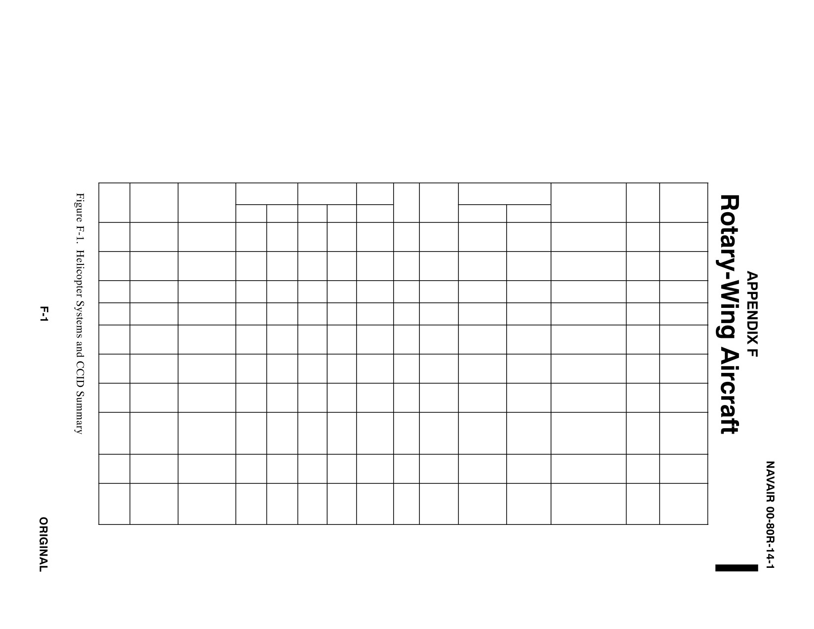
HELICOPTER AIRCRAFT SYSTEMS AND
CRASH CREW INFORMATION DIAGRAMS SUMMARY
FUEL (GAL)
OIL (GAL)
OXYGEN
ORDNANCE
AIRFRAME
PNEU
TYPE
NAME
MATERIALS
INT
EXT
ENG
HYD
BOTTLE
SYS
GUN
FWD FIRE
FREE FALL
PYROTECHNICS
BTRY
S.O.B.
ALUMINUM
PYLON EJECTOR
SEA
STEEL
(2) 100
N2
MISSILES
CARTRIDGES(4)STA.
AH-1
304
OR
3.7
3.4
NONE
3000
20 MM
NONE
2
2
COBRA
TITANIUM
ROCKETS
CHAFF/FLARES
FIBERGLASS
(2) 75
PSI
CANOPIES
ALUMINUM
PYLON EJECTOR
SUPER
STEEL
(2) 100
N2
MISSILES
CARTRIDGES(4)STA.
AH-1Z
403
OR
14 QT
10.8 QT
NONE
3000
20 MM
NONE
1
2
COBRA
TITANIUM
ROCKETS
CHAFF/FLARES
(2) 75
PSI
FIBERGLASS
CANOPIES
ALUMINUM
N2
GAV-2B/A
UH-1/
IROQUOIS/
STEEL
212
NONE
3.3
3
NONE
1500
M-60
NONE
NONE
CHAFF/FLARES
1
15
HH-1
HUEY
FIBERGLASS
PSI
50 CAL
ALUMINUM
N2
GAV-2B/A
IROQUOIS/
(2)
MISSILES
UH-1Y
STEEL
385
14 QT
10.8
NONE
3000
M-60
NONE
CHAFF/FLARES
1
12
HUEY
77
ROCKETS
CARBON FIBER
PSI
50 CAL
ALUMINUM
STEEL
(2)
N2
H-3
SEA KING
831
18.6
2
NONE
3000
NONE
NONE
NONE
SMOKE MARKERS
1
5
TITANIUM
110
PSI
FIBERGLASS
ALUMINUM
SEA
STEEL
380
(2)
N2
(2) 50 CAL
CHAFF/FLARES
H-46
HH-46D
NONE
13 E
5.8 E
295 IN3
3000
OR
NONE
NONE
1
28
KNIGHT
TITANIUM
(CH-46E)
FIBERGLASS
AUX 729
(CH-46E)
PSI
(2) M-60
ALUMINUM
N2
(2) EXT FUEL TANK
SEA
STEEL
(2)
H-53D
638
1300
8
6.5
NONE
3000
NONE
NONE
EJECTOR CARTRIDGES
0
41
STALLION
TITANIUM
50 CAL
PSI
CHAFF/FLARES
FIBERGLASS
ALUMINUM
PYLON EJECTOR
SUPER
STEEL
MH-53
MH-53
CARTRIDGES (4) STA
MH-53
SEA
GPH EPOXY
3212
CH-53
9.3
N2
CHAFF/FLARES
3
H-53E
11.7
NONE
3000
(2) 50 CAL
NONE
NONE
58
STALLION/
TITANIUM
CH-53
1300
CH-53
UTILITY HOIST CART.
CH-53
SEA DRAGON
FIBERGLASS
977
6.5
PSI
SINGLE PT CARGO
1
KEVLAR
HOOK CART
TH-57B
ALUMINUM
SEA
5.5
1.0
1
TH-57
STEEL
91
NONE
NONE
NONE
NONE
NONE
NONE
NONE
5
RANGER
QTS
PT
TH-57C
FIBERGLASS
2
ALUMINUM
GAU-16
MH-60S —16
STEEL
MK 46
GAU 21
SH-60B — 5
GPH EPOXY
3
N2
MK 50
H-60
SEAHAWK
590
320
10.8
NONE
3000
M240
HELLFIRE
SMOKE MARKERS
1
H-60F — 6
TITANIUM
CT
TORPEDOES
FIBERGLASS
PSI
M240D
SONOBUOY
H-60H — 11
KEVLAR
M60
MH-60R — 7
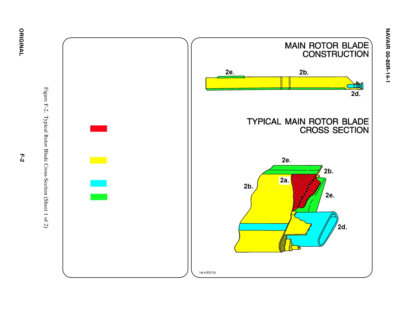
HELICOPTER MAIN ROTOR BLADE
CONSTRUCTION (TYPICAL)
1.
The main rotor blades of a helicopter
have titanium spars with Nomex cores
and fiberglass/graphite outer skin. The
low weight, high strength ratio of these
materials, combined with unlimited
configuration possibilities make them
ideal for use in naval aircraft.
2.
The helicopter main rotor blade
construction consists of the following
material:
a. Graphite Epoxy
b. Other
ąFiberglass
ąNickel
ąRubber
c. N/A
d. Titanium
e. Aluminum
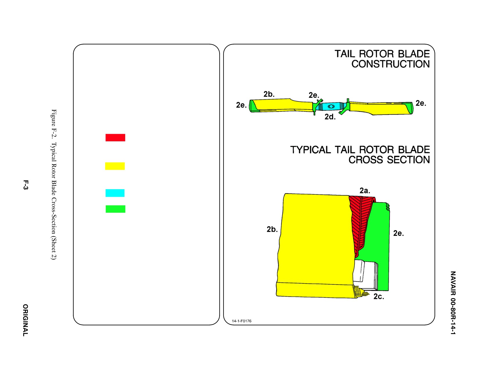
HELICOPTER TAIL ROTOR BLADE
CONSTRUCTION (TYPICAL)
1. Helicopter tail rotor blades are constructed
of laminated composite materials which
are reinforced with carbon/graphite fibers.
This material provides superior stiffness,
high strength to weight ratio, and the ease
of fabrication.
2. The helicopter tail rotor blade construction
consists of the following material:
a. Graphite Epoxy
b. Other
ąFiberglass
ąRubber
c. N/A
d. Titanium
e. Aluminum
SPECIAL TOOLS/EQUIPMENT
Power Rescue Saw
Crash Axe
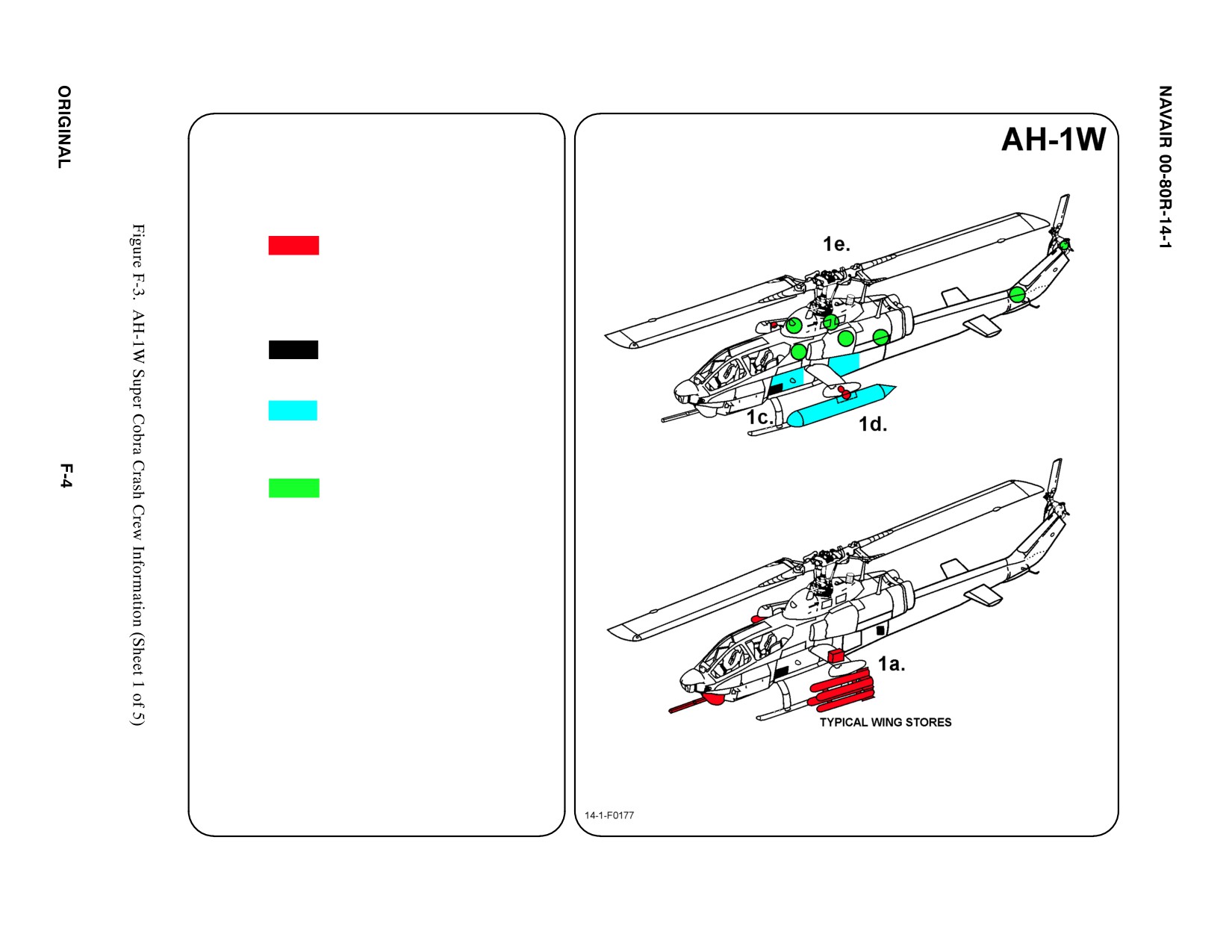
1.
GENERAL AIRCRAFT INFORMATION
a. Armament
4 Stub Wing Stations
20mm Nose Gun
Chaff/Flares Ejector
ącartridges (TMS)
b. N/A
c. Battery
2 (1 port and
ą1 starboard side
ąbattery compartment)
d. Fuel
Internal 304 gal
External two 100 gal
ąand/or two 77 gal
ąaux tanks
e. Oil
Engine 3.6 gal
Hydraulic 3.4 gal
Transmission 11.6 gal
C-Box/Combining
ąGearbox 20 qts
f. Pneumatic
2000 PSI
ąSystem
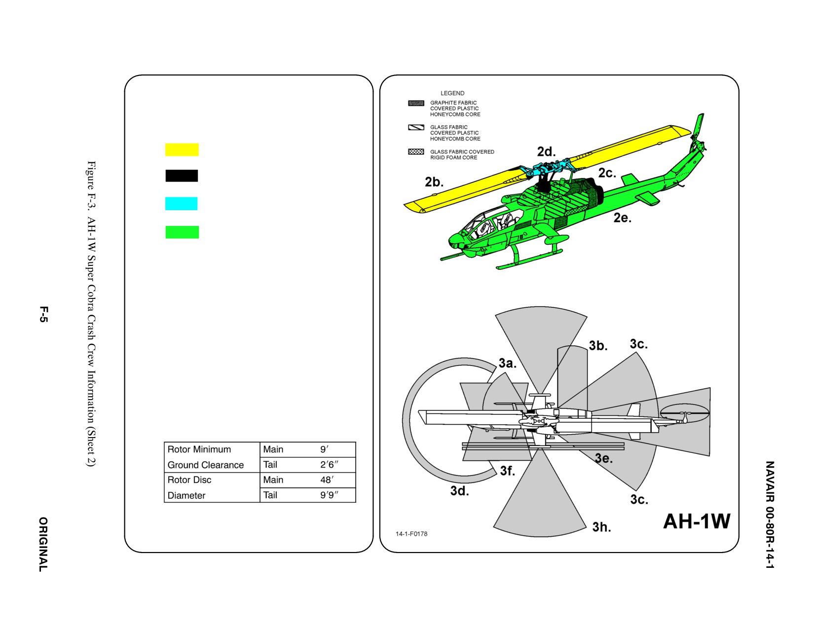
2.
AIRFRAME MATERIALS
a. Composite Materials (See Legend)
b. Other
ąFiberglass
c. Steel
d. Titanium
e. Aluminum
f. N/A
g. N/A
3.
AIRCRAFT DANGER AREAS
a. Inlet Suction — 6i
b. Turbine blade Failure — 300i
c. Engine Exhaust — 24i
d. Nose Gun
220_ Pattern FWD of Gun
50_ Below Horizontal Plane
30_ Above Horizontal Plane
e. Missile Exhaust
f. Missile FWD Fire Zone
g. Rotors
h. Chaff/Flares
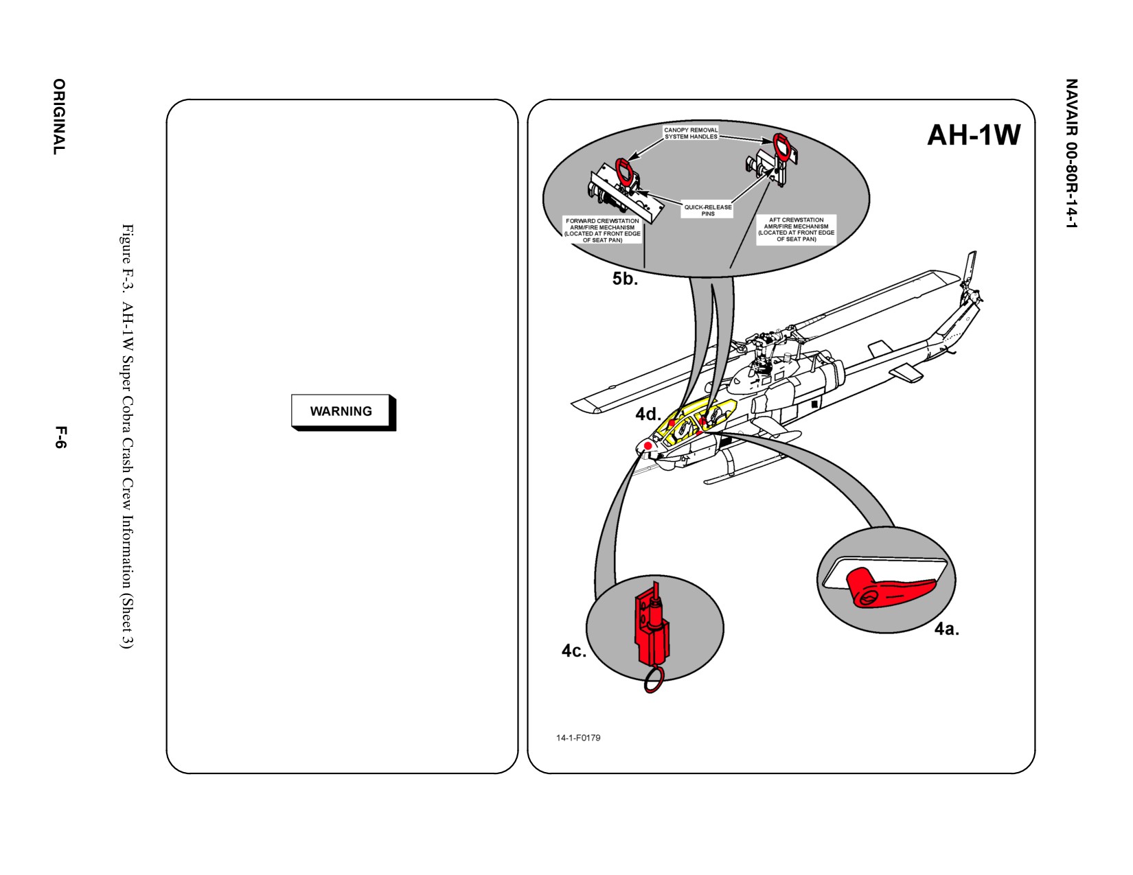
4. AIRCRAFT ENTRY
a. NORMAL ENTRY
The pilot canopy door opening is on the RH
side and the copilot/gunner door is on LH
side. Both doors are pneumatically opened
and closed from outside. To open either
door, TURN door handle and it will
automatically raise to full open position.
b. N/A
c. EMERGENCY ENTRY
The external canopy jettison system is
located in the nose of the aircraft. OPEN
access door, REMOVE safety pin from
arm/fire mechanism, ROTATE ring 90_
COUNTERCLOCKWISE, and PULL ring to
shatter windows.
D Do not shatter canopies with fuel in cockpit
area, fire or explosion may result. Ensure
personnel are clear of cockpit area before
utilizing jettison system.
D Personnel within 50 ft of aircraft could be
injured by debris when jettison system is used.
d. FORCED ENTRY
Canopies are made of acrylic plastic and
may be cut using a power rescue saw or
crash axe. CUT along canopy frames.
5. CANOPY SAFETY
Canopies have a linear explosive system used
to cut the windows from support structure for
emergency entrance or exit.
a. N/A
b. JETTISON HANDLE
To safe canopy, INSERT safety pins in pilot's
and copilot/gunner's Canopy Jettison Handle.
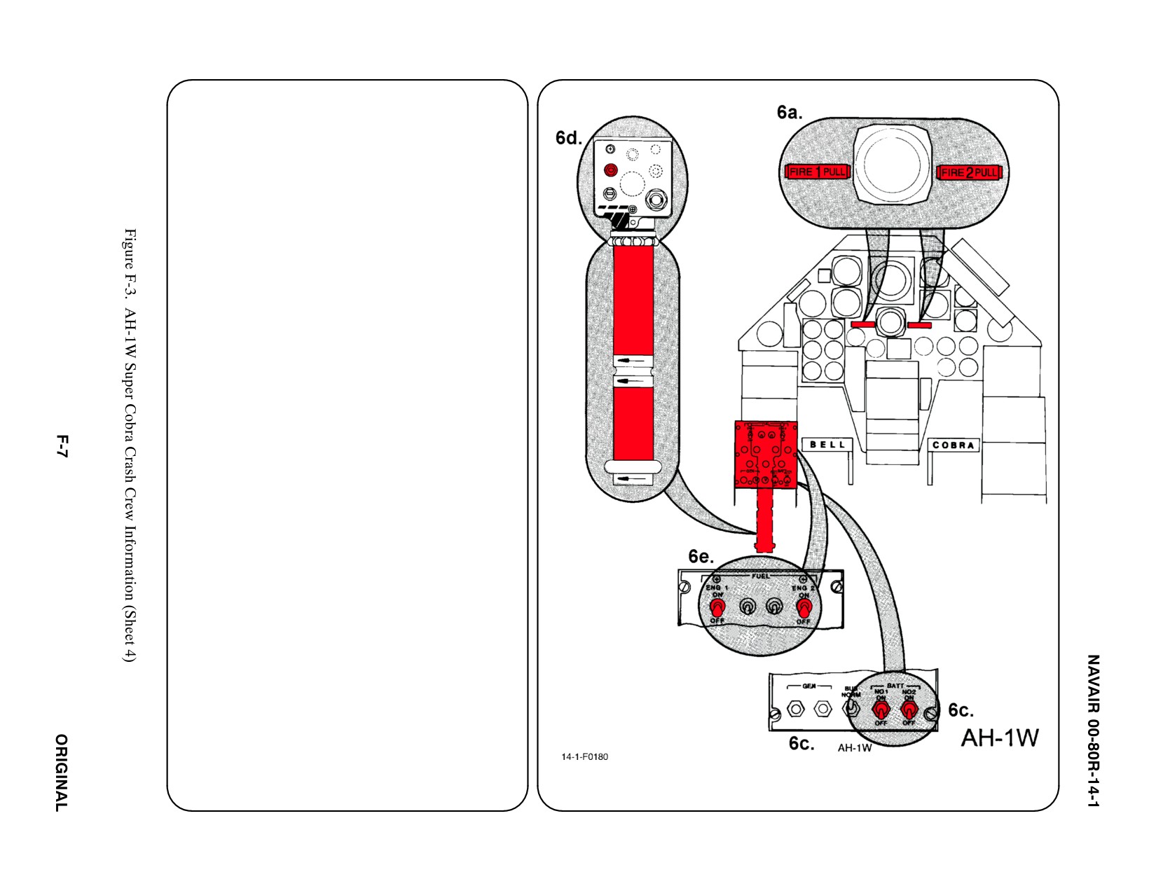
6. ENGINE SHUTDOWN (NORMAL)
a. N/A
b. N/A
c. BATTERY SWITCHES
PLACE Battery Switches in OFF position.
d. IDLE STOP RELEASE
SWITCH/THROTTLES
MOVE Idle Stop Release Switch to Engine
1 position and CLOSE Throttle for Engine 1
by TURNING grip to the Right. REPEAT
procedure for Engine 2.
Note
Close throttle within 5 seconds after actuating
idle stop release.
e. FUEL SHUTOFF SWITCHES
PLACE both Engine 1 and 2 Fuel Shutoff
Switches in OFF position.
f. N/A
g. N/A
12345
6.
ENGINE SHUTDOWN (EMERGENCY)
a. FIRE PULL HANDLES
PULL both number 1 and number 2 Fire Pull
Handles.
b. N/A
c. BATTERY SWITCHES
PLACE Battery Switches in OFF position.
d. N/A
e. N/A
f. N/A
g. N/A
7.
BATTERY(ies)
Disconnect if time permits.
a. N/A
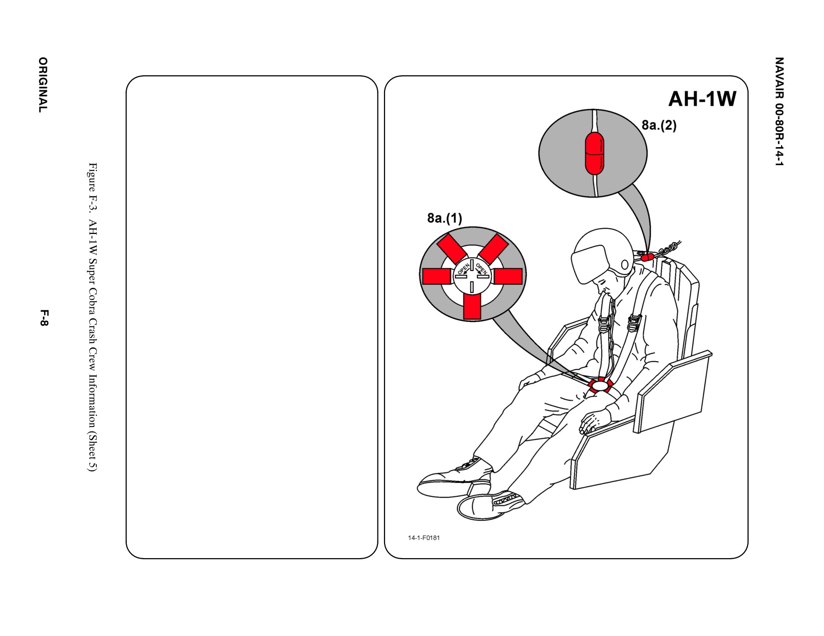
8. CREW RELEASE
Pilot and copilot/gunner are attached to the
seats by shoulder harnesses secured to lap
belts with quick disconnects.
a. PERSONNEL SERVICE, QUICK
DISCONNECT
(1) TWIST quick disconnect lever to
release shoulder harnesses and lap
belt.
(2) MICROPHONE CORD: Disconnect
microphone cord prior to lifting
crewman from seat.
b. N/A
c. N/A
d. N/A
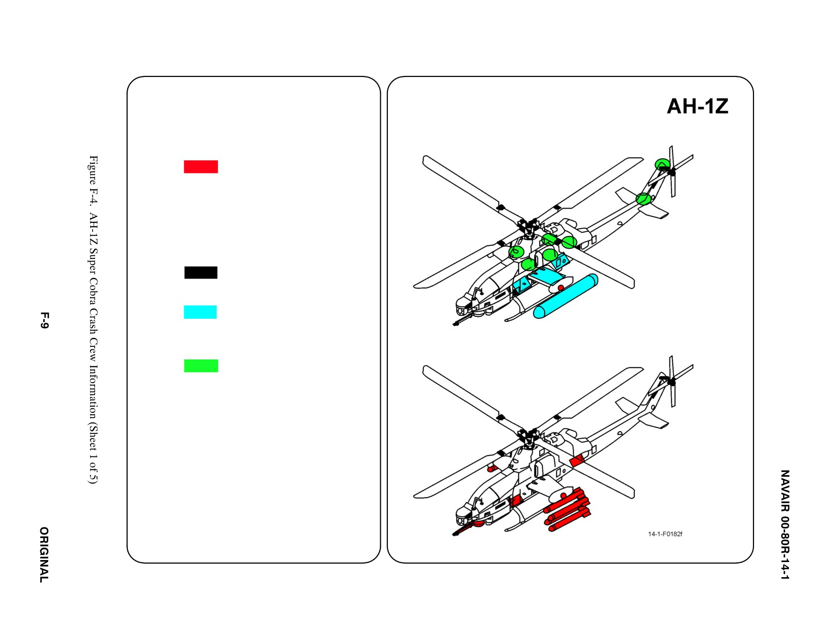
SPECIAL TOOLS/EQUIPMENT
Power Rescue Saw
Crash Axe
1.
GENERAL AIRCRAFT INFORMATION
a.
Armament
2 Wing Tip Stations
ą(AIM-9)
4 Stub Wing Stations
20mm Nose Gun
Chaff/Flares
Ejector Cartridges
ą(TMS)
b.
N/A
c.
Battery
1 LH Side of Battery
ąCompartment
d.
Fuel
Internal 403 gal
External two 100 gal
ąor
two 77 gal
e.
Oil
Engine 14 qt
Hydraulic 10.8 qt
Transmission 18.9 qt
Combining Gearbox
ą18.4 qt
f.
Pneumatic
3000 psi
ąSystem
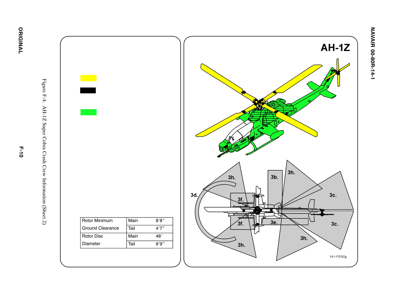
2.
AIRFRAME MATERIALS
a. N/A
b. Other
ąCarbon Fiber
ąComposite Materials
c. Steel
d. N/A
e. Aluminum
f. N/A
g. N/A
3.
AIRCRAFT DANGER AREAS
a. Inlet Suction — 6i
b. Turbine Blade Failure — 300i
c. Engine Exhaust — 24i
d. Nose Gun
ą220_ Pattern FWD of Gun
ą50_ Below Horizontal Plane
ą30_ Above Horizontal Plane
e. Missle Exhaust
f. Missle FWD Fire Zone
g. Rotors
h. Chaff/Flares
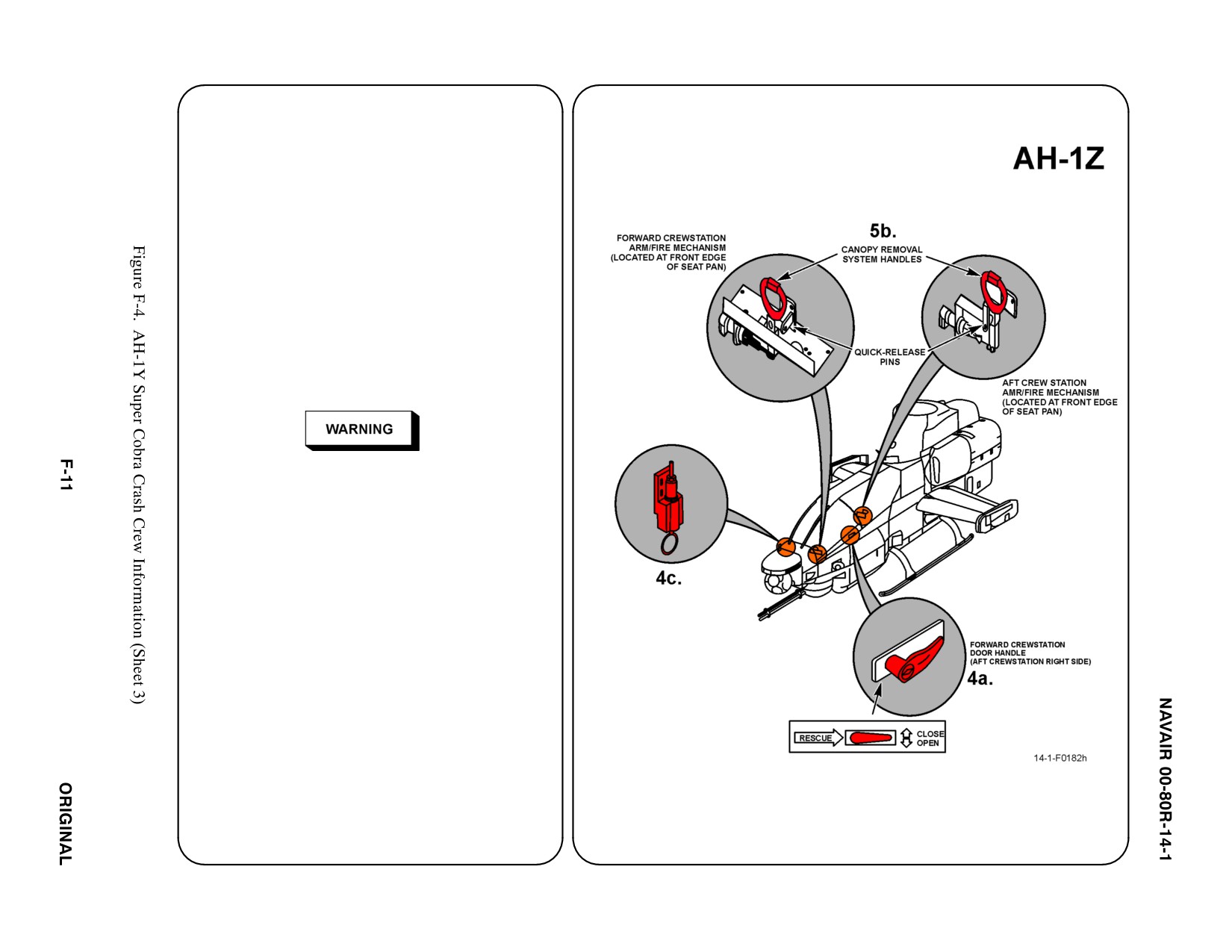
4. AIRCRAFT ENTRY
a. NORMAL ENTRY
The pilot canopy door opening is on the RH
side and the copilot/gunner door is on the LH
side. Both doors are pneumatically opened
and closed from outside. To open either door,
TURN door handle and it will automatically
raise to full open position.
b. N/A
c. EMERGENCY ENTRY
The external canopy jettison system is located
in the nose of the aircraft. OPEN access door,
REMOVE safety pin from arm/fire mechanism,
ROTATE ring 90_ COUNTERCLOCKWISE,
and PULL ring to shatter windows.
D Do not shatter canopies with fuel in cockpit
area, fire or explosion may result. Ensure
personnel are clear of cockpit area before
utilizing jettison system.
D Personnel within 50 ft of aircraft could be
injured by debris when jettison system is used.
d. FORCED ENTRY
Canopies are made of acrylic plastic and may
be cut using a power rescue saw or crash axe.
CUT along canopy frames.
5. CANOPY SAFETY
Canopies have a linear explosive system used to
cut the windows from support structure for
emergency entrance or exit.
a. N/A
b. JETTISON HANDLE
To safety canopy, INSERT safety pins in pilot's
and copilot/gunner's Canopy Jettison Handle.
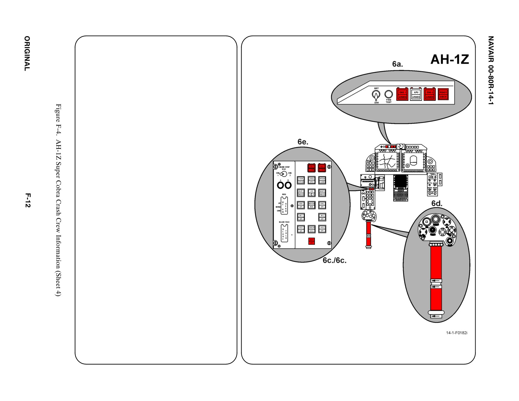
6. ENGINE SHUTDOWN (NORMAL)
a. N/A
b. N/A
c. BATTERY PUSH BUTTON
PUSH Battery button off.
d. IDLE STOP RELEASE SWITCH/THROTTLES
MOVE Idle Stop Release to Engine 1 position
(left) and CLOSE Throttle for Engine 1 by
TURNING grip to the right. MOVE Idle Stop
Release to Engine 2 position (right) and
CLOSE Throttle for Engine 2 by TURNING grip
to the right.
Note
Close throttle within 5 seconds after actuating idle
stop release.
e. FUEL SHUTOFF PUSH BUTTONS
LIFT clear button covers and PUSH fuel shutoff
buttons for Engine 1 and 2.
f. N/A
g. N/A
12345
6.
ENGINE SHUTDOWN (FIRE EMERGENCY)
a. FIRE PUSH BUTTON ANNUNCIATORS
LIFT Engine 1 and 2 clear fire button covers
and PUSH fire buttons. ARMED light on both
push buttons will illuminate, and the READY
light will illuminate on the discharge button.
PUSH discharge button to discharge fire bottle.
b. N/A
c. BATTERY BUTTON
PUSH Battery button off.
d. N/A
e. N/A
f. N/A
g. N/A
7. BATTERY
Disconnect if time permits
a. N/A
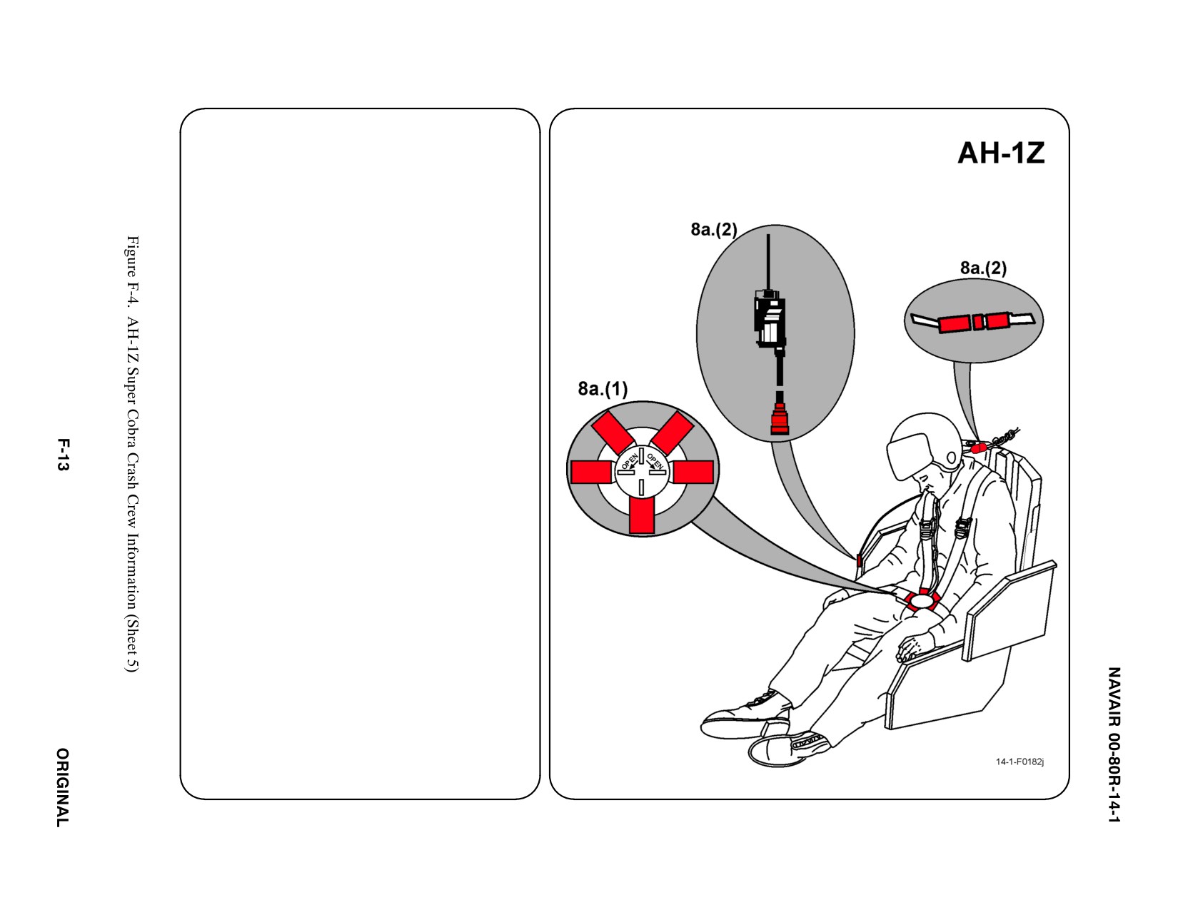
8. CREW RELEASE
Pilot and copilot/gunner are attached to the
seats by shoulder harnesses secured to lap
belts with quick disconnects.
a. PERSONNEL SERVICE, QUICK
DISCONNECT
(1) TWIST quick disconnect lever to release
shoulder harness and lap belt.
(2) HELMET CORDS: DISCONNECT
microphone and helmet cords prior to
lifting pilot from seat.
b. N/A
c. N/A
d. N/A
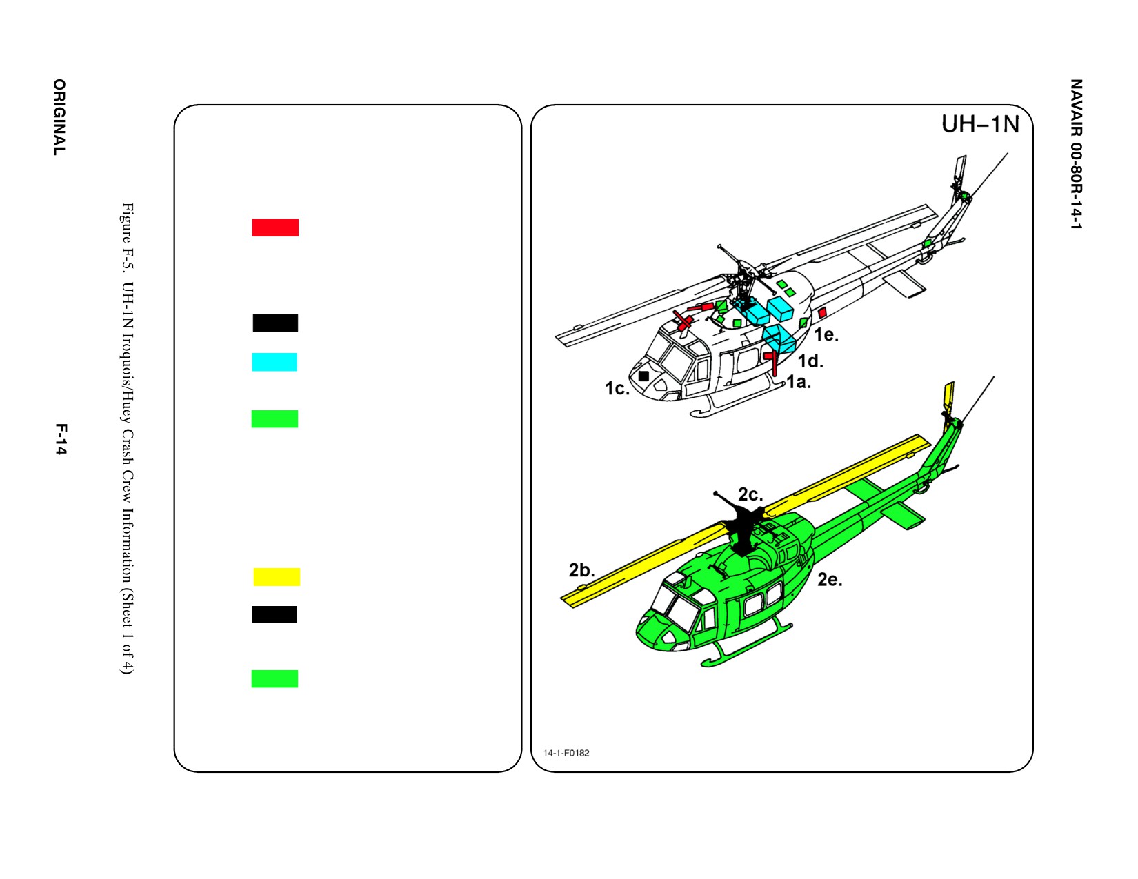
SPECIAL TOOLSIEQUIPMENT
Power Rescue Saw
Crash Axe
1.
GENERAL AIRCRAFT INFORMATION
a. Armament
GAU-16A (50 cal)
GAU-17/A (7.62mm)
M240D (7.62mm)
Rocket LAU-68
b. N/A
c. Battery
1
d. Fuel
Internal 212/242 gal
Auxiliary Tanks
165 or 350 gal
e. Oil
Engine 3.25 gal
Hydraulic 4 pt
Transmission 2.35 gal
f. Pneumatic
1500 PSI
ąSystem
2.
AIRFRAME MATERIALS
a. N/A
b. Other
ąFiberglass
c. Steel
d. N/A
e. Aluminum
f. N/A
g. N/A
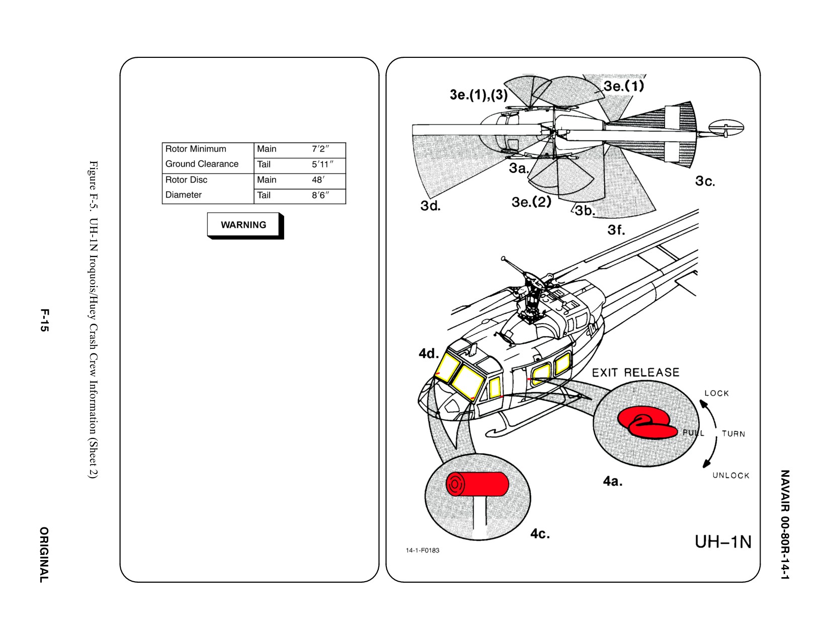
3. AIRCRAFT DANGER AREAS
a. Inlet Suction — 6i
b. Turbine Blade Failure — 300i
c. Engine Exhaust — 23i
d. Rotors
Rotor blade may flap down as low as 5 feet.
e. Guns
(1) GAU-16A — 172_
(2) GAU-17A — 176_
(3) M240D — 172_
f. Chaff/Flares
4.
AIRCRAFT ENTRY
a. NORMAL ENTRY
(1) ROTATE Crew Door Handle, PULL OUT
and FWD to open door (both sides).
(2) ROTATE Passenger Cargo Door Handle
DOWN and SLIDE door AFT to open
(both sides).
b. N/A
c. EMERGENCY ENTRY
If the pilot/copilot crew exits are jammed and
access cannot be gained through the
passengers' exits, SLIDE or BREAK the pilot
or copilot windows, REACH FWD and PULL
jettison able door release. If the doors do not
jettison, BREAK the windshield or any other
windows to gain entrance.
d. FORCED ENTRY
Windows are made of acrylic plastic and may
be cut using a power rescue saw or crash
axe. CUT along window frames.
5.
N/A
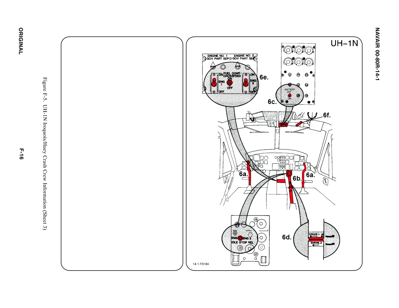
6.
ENGINE SHUTDOWN
a.
CYCLE CONTROL STICK
CENTER either Cycle Control Stick and
HOLD.
b. COLLECTIVE PITCH LEVER
PUSH the Collective Pitch Lever Down into
DOWN LOCK.
c.
BATTERY SWITCH
PLACE Battery Switch in OFF position.
d. THROTTLES/ENGINE IDLE RELEASE
STOP SWITCHES
ENGAGE Engine 1 Idle Release Stop
Switch (on pilot's collective only) then
CLOSE Throttle 1 by TWISTING grip to
RIGHT to shut down engine 1. REPEAT
procedure for engine 2.
e.
FUEL SHUTOFF SWITCHES
PLACE Engine 1, Engine 2, and Crossfeed
Fuel Control Switches in OFF position.
f.
ROTOR BRAKE
PULL DOWN on Rotor Brake Actuator
Handle to position of greatest pressure and
HOLD until rotor stops turning.
g. N/A
7.
BATTERY
Battery is located in the nose compartment.
Disconnect, time permitting.
a. N/A
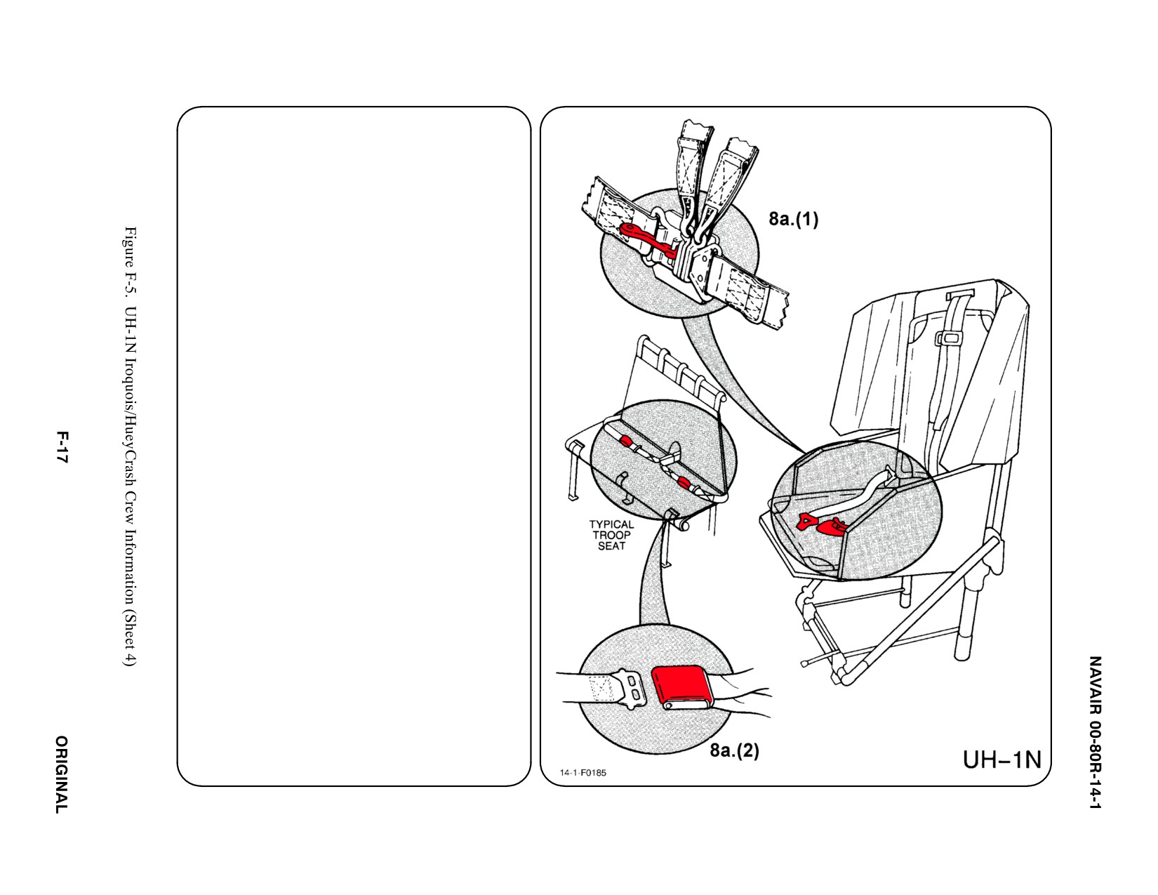
8. CREW RELEASE
The pilot/copilot are attached to the seats by
shoulder harnesses secured to lap belt with
quick disconnects. Passengers have lap belts
only.
a. PERSONNEL SERVICE, QUICK
DISCONNECT
(1) LIFT quick disconnect lever to release
shoulder harnesses and lap belt.
(2) PASSENGER: LIFT buckle cover to
release lap belt (airline type).
b. N/A
c. N/A
d. N/A
SPECIAL TOOLS/EQUIPMENT
Power Rescue Saw
Crash Axe
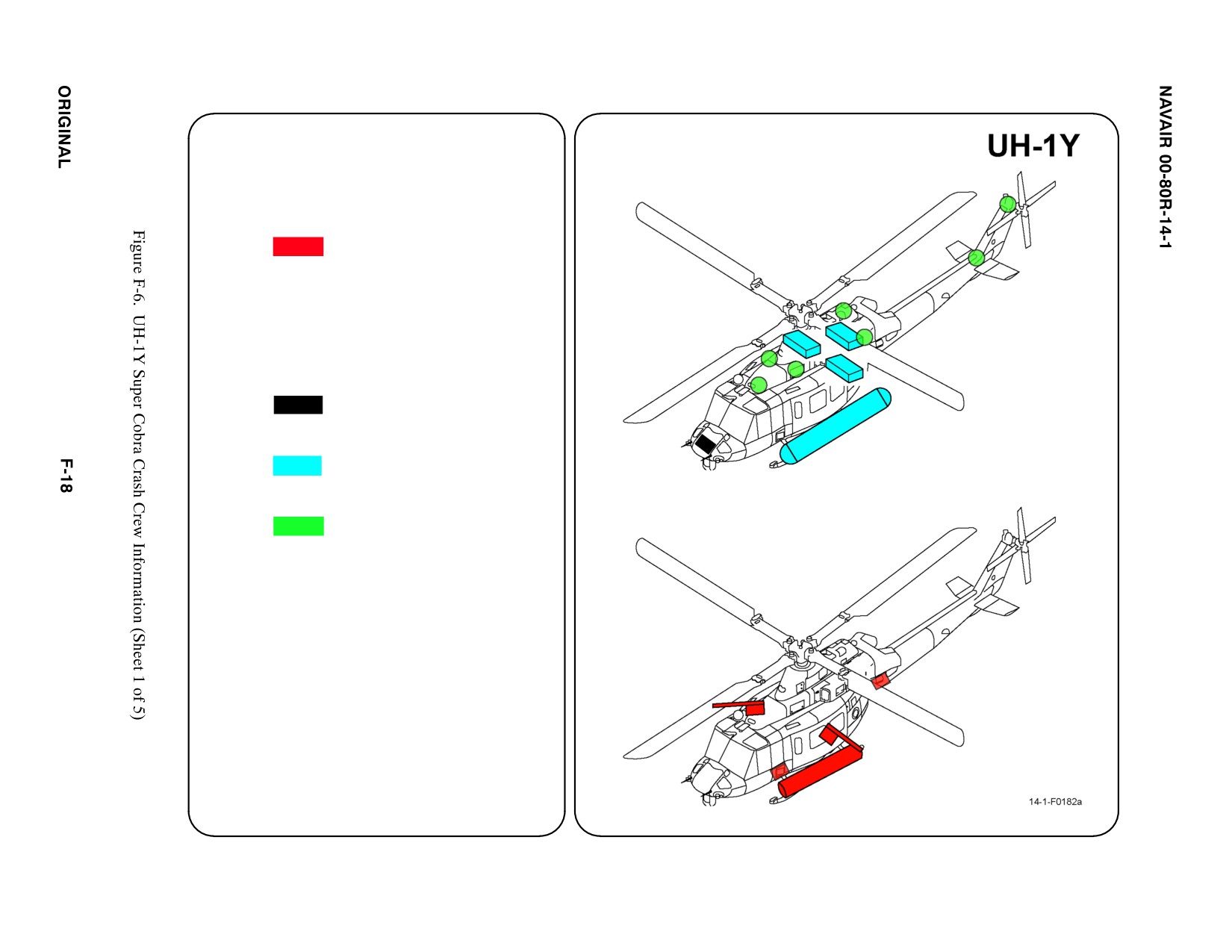
1. GENERAL AIRCRAFT INFORMATION
a. Armament
GAU-16 (.50)
GAU-17 (7.62)
M240 (7.62)
Rocket Pods
Chaffs/Flares
Ejector Cartridges
ą(TMS)
b. N/A
c. Battery
1 Nose Compartment
d. Fuel
Internal 385 gal
External two 77 gal
e. Oil
Engine 14 qt
Hydraulic 10.8 qt
Transmission 18.9 qt
Combining Gearbox
ą18.4 qt
f. Pneumatic
3000 psi
ąSystem
2.
AIRFRAME MATERIALS
a. N/A
b. Other
ąCarbon Fiber
ąComposite Materials
c. Steel
d. N/A
e. Aluminum
f. N/A
g. N/A
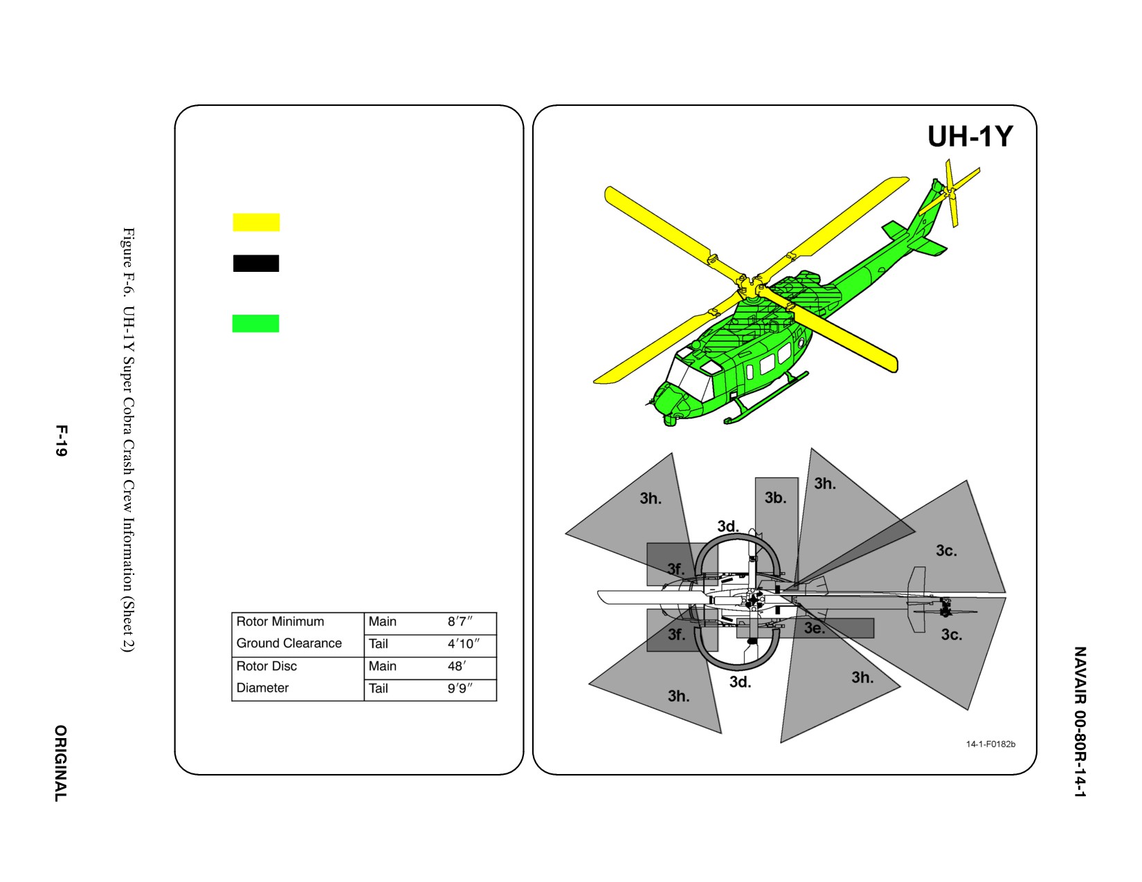
3.
AIRCRAFT DANGER AREAS
a. Inlet Suction — 6i
b. Turbine Blade Failure — 300i
c. Engine Exhaust — 24i
d. Guns
(1) GAU-16 — 172_
(2) GAU-17 — 176_
(3) M240 — 172_
e. Rocket Exhaust
f. Rocket FWD Fire Zone
g. Rotors
h. Chaff/Flares
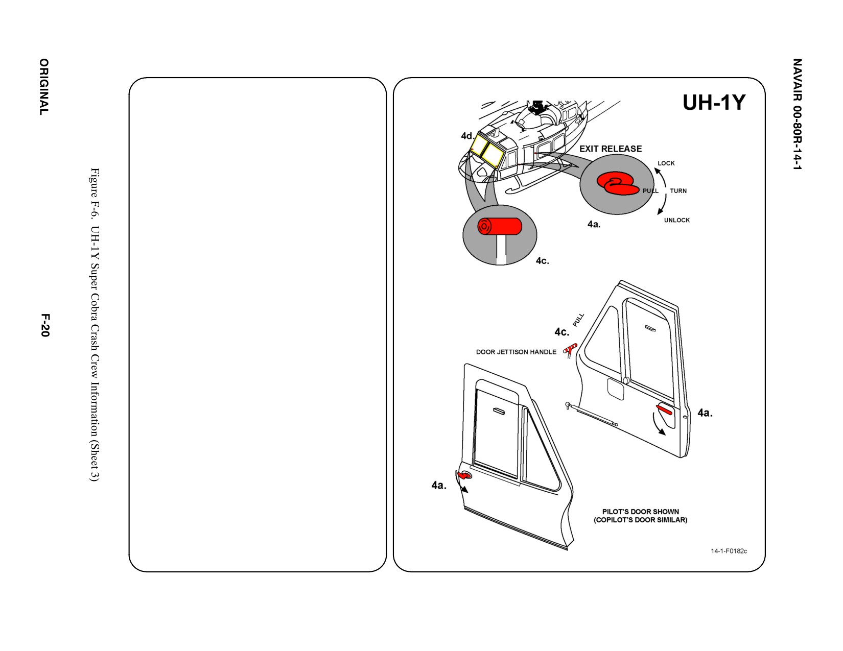
4.
AIRCRAFT ENTRY
a.
NORMAL ENTRY
(1) ROTATE Crew Door Handle, PULL OUT
and FWD to open door (both sides).
(2) ROTATE Passenger Cargo Door Handle
DOWN and SLIDE door AFT to open
(both sides).
b. N/A
c.
EMERGENCY ENTRY
If the pilot/copilot crew exits are jammed
and access cannot be gained through the
passengers' exits, SLIDE or BREAK the
pilot or copilot windows, REACH FWD and
PULL jettisonable door release. If the doors
do not jettison, BREAK the windshield or
any other windows to gain entrance.
d. FORCED ENTRY
Windows are made of acrylic plastic and
may be cut using a power rescue saw or
crash axe. CUT along window frames.
5.
N/A
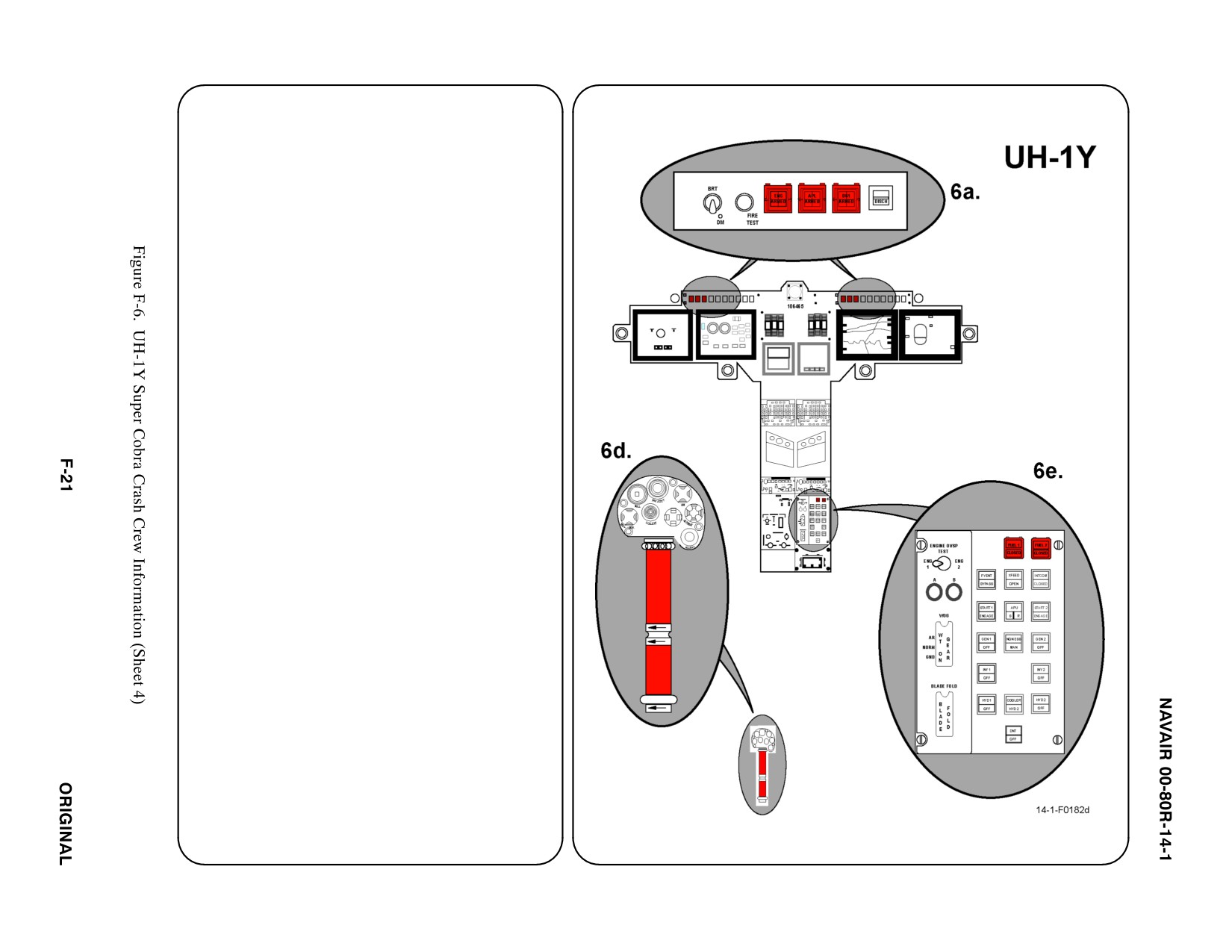
6. ENGINE SHUTDOWN (NORMAL)
a. N/A
b. N/A
c. BATTERY PUSH BUTTON
PUSH Battery button off.
d. IDLE STOP RELEASE SWITCH/THROTTLES
MOVE Idle Stop Release to Engine 1 position
(left) and CLOSE Throttle for Engine 1 by
TURNING grip to the right. MOVE Idle Stop
Release to Engine 2 position (right) and
CLOSE Throttle for Engine 2 by TURNING grip
to the right.
Note
Close throttle within 5 seconds after actuating idle
stop release.
e. FUEL SHUTOFF PUSH BUTTONS
LIFT clear button covers and PUSH fuel shutoff
buttons for Engine 1 and 2.
f. N/A
g. N/A
12345
6.
ENGINE SHUTDOWN (FIRE EMERGENCY)
a. FIRE PUSH BUTTON ANNUNCIATORS
LIFT Engine 1 and 2 clear fire button covers
and PUSH fire buttons. ARMED light on both
push buttons will illuminate, and the READY
light will illuminate on the discharge button.
PUSH discharge button to discharge fire bottle.
b. N/A
c. BATTERY BUTTON
PUSH Battery button off.
d. N/A
e. N/A
f. N/A
g. N/A
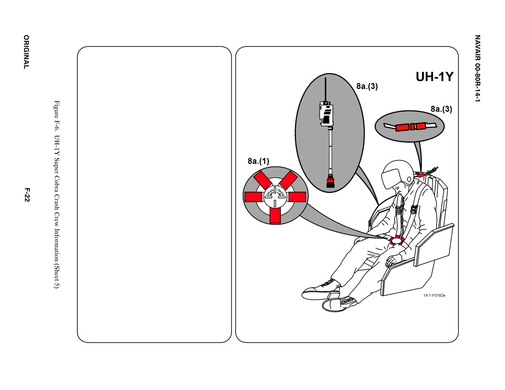
7.
BATTERY
Disconnect if time permits
a. N/A
8.
CREW RELEASE
Pilot and copilot/gunner are attached to the
seats by shoulder harnesses secured to lap
belts with quick disconnects.
a. PERSONNEL SERVICE, QUICK
DISCONNECT
(1) TWIST quick disconnect lever to release
shoulder harness and lap belt.
(2) PASSENGER RESTRAINTS: TWIST
quick disconnect lever to release
shoulder harness and lap belt.
(3) HELMET CORDS: DISCONNECT
microphone and helmet cords prior to
lifting pilot from seat.
b. N/A
c. N/A
d. N/A
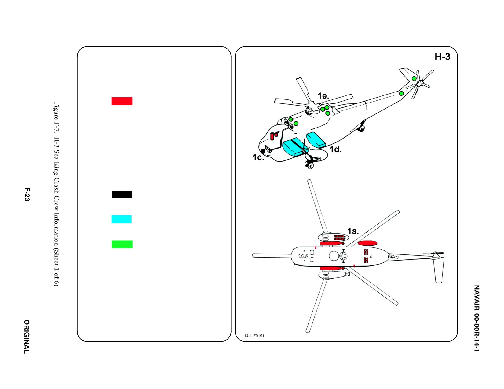
SPECIAL TOOLS/EQUIPMENT
Power Rescue Saw
Crash Axe
1. GENERAL AIRCRAFT INFORMATION
a. Armament
Launcher Ejector
ąCartridges
Sonobuoy Launcher
ą(H-3)
Chaff Dispensers
ą(H-3)
Marine Marker
ąLauncher
Smoke Marker
ąLauncher System
Torpedoes
b. N/A
c. Battery
1
d. Fuel
Internal
ą848 gal
e. Oil
Engine 5.4 gal
Hydraulic 2 gal
Transmission 11 gal
f. Pneumatic
3000 PSI
ąSystem
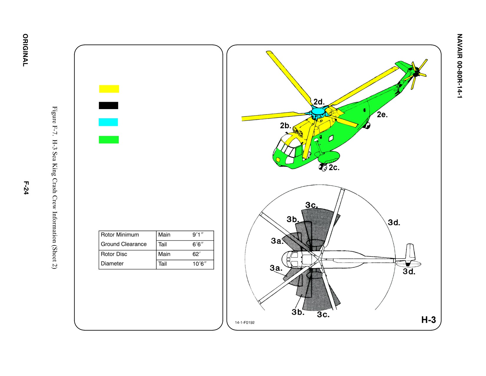
2. AIRFRAME MATERIALS
a. N/A
b. Other
Fiberglass/Magnesium
c. Steel
d. Titanium
e. Aluminum
f. N/A
g. N/A
Note
Gear boxes are made of magnesium.
3. AIRCRAFT DANGER AREAS
a. Inlet Suction — 4i
b. Turbine Blade Failure
c. Engine Exhaust — 20i
d. Rotors
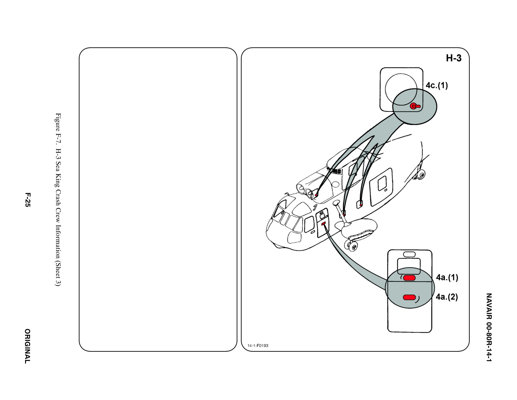
4. AIRCRAFT ENTRY
a. NORMAL ENTRY
(1) Enter through the personnel door on LH
side of aircraft. The upper door may be
opened at center of door below window
by turning handle. To open, PUSH FWD
part of handle and TURN
COUNTERCLOCKWISE.
Note
On helicopters not modified by AFC No. 301, the
upper door handle is located in well at AFT
bottom of window.
(2) The lower door may be opened by
turning handle at center of door. To
open, PUSH FWD part of handle, TURN
COUNTERCLOCKWISE and PULL
door open.
b. N/A
c. EMERGENCY ENTRY
For emergency access, cabin windows,
cabin doors, and pilot/copilot's jettison able
windows may be opened from the outside.
(1) Cabin windows are equipped with pull
tab, lower AFT corner. To open, PULL
tab and PUSH panel INWARD.
123
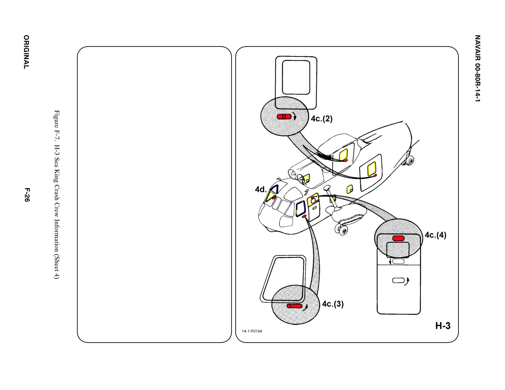
4. AIRCRAFT ENTRY (CONT.) ab
c. EMERGENCY ENTRY (CONT.) (1)
(2) To gain access through the window in
the cabin door (RH side of aircraft),
TURN handle (lower AFT corner)
CLOCKWISE and PULL.
Note
UH-3A has 2 cabin doors, one on each side of
aircraft. RH door operates as described in 4b.(2).
LH door, upper section, opens by turning handle
FWD.
(3) To jettison pilot/copilot windows PRESS
handle to extend, then TURN handle
COUNTERCLOCKWISE and PULL
window OUTWARD.
(4) Upper half of personnel door may be
removed by ROTATING handle DOWN.
d. FORCED ENTRY
Windows are made of acrylic plastic and
may be cut using a power rescue saw or
crash axe. Areas marked on fuselage CUT
HERE also may be cut for access. CUT
along window frames and marked fuselage
entry areas only.
5. N/A
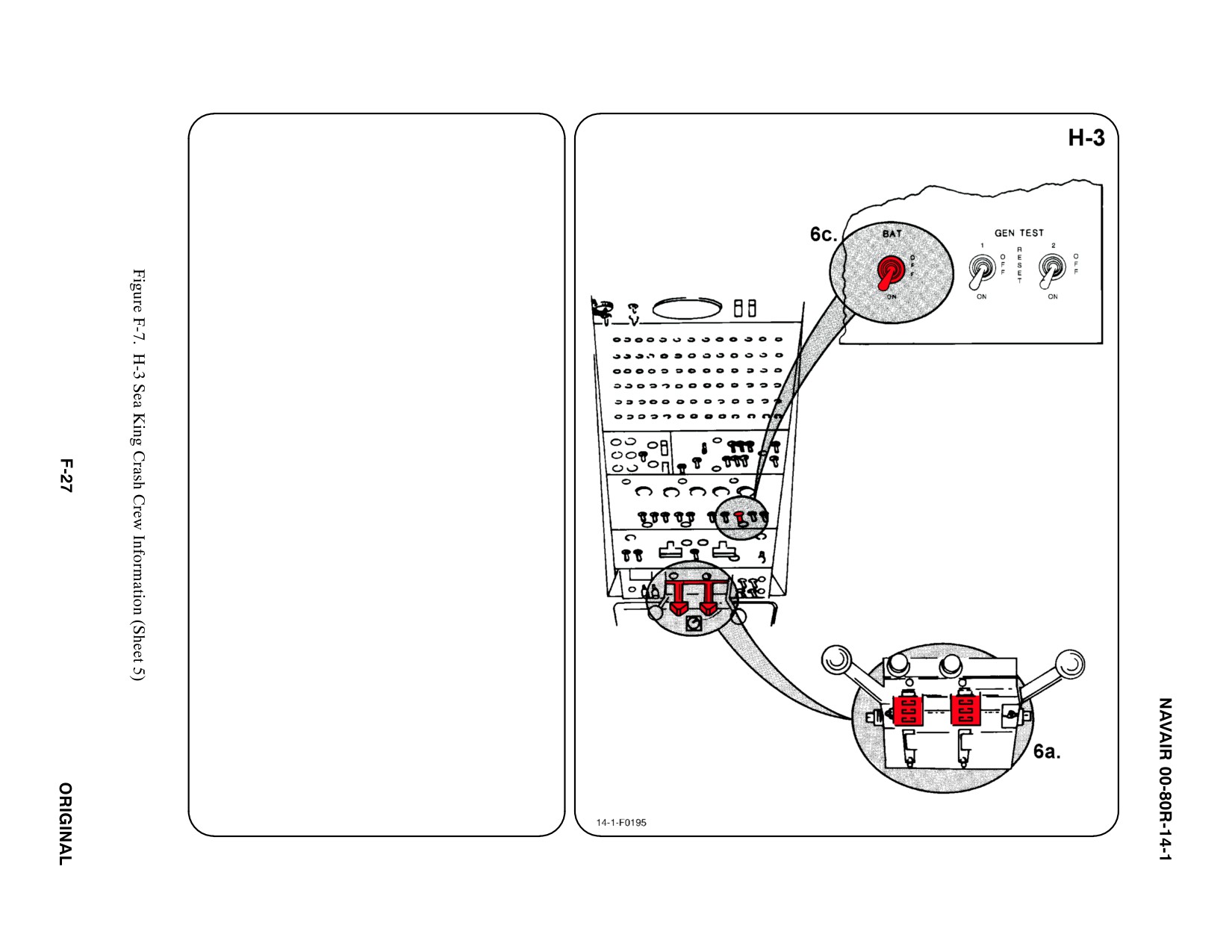
6. ENGINE SHUTDOWN
Engine may be shut down by engine speed
selector levers fuel shutoff handles located on
the center overhead control panel.
a. ENGINE SPEED SELECTOR LEVERS
PLACE Selector Levers in SHUTOFF
position by PULLING Speed Handles AFT.
Note
A limit stop or friction control prevents
inadvertent retarding of speed selector below
ground idle. PULLING speed selector down
bypasses this stop.
b. N/A
c. BATTERY SWITCH
PLACE Battery Switch in OFF position.
d. N/A
e. N/A
f. N/A
g. N/A
7. BATTERY
The battery is located in the nose section FWD
of the pilot's compartment and is accessible
from outside.
a. N/A
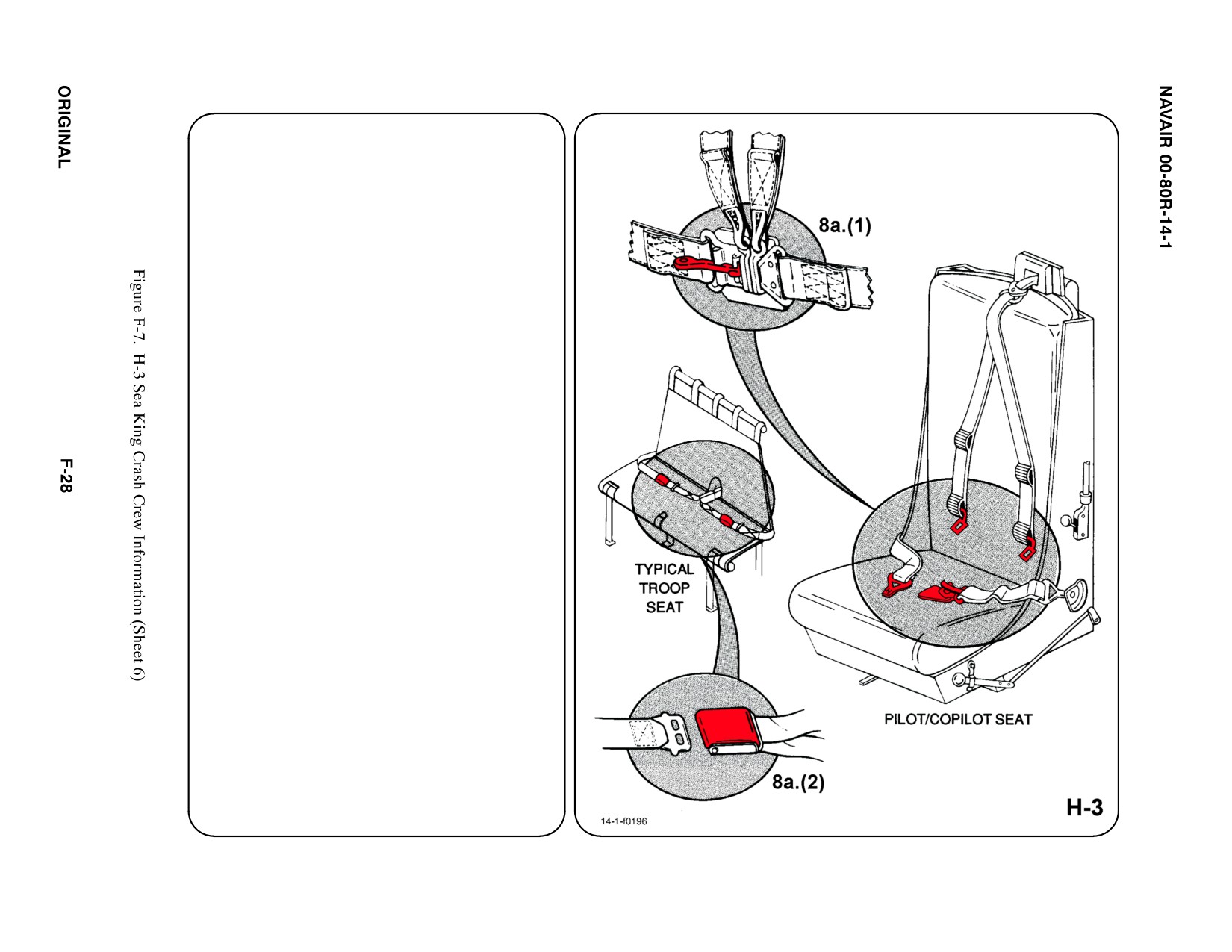
8. CREW RELEASE
The pilot, copilot, and sensor operators are
attached to the seat by shoulder harnesses
secured to a lap belt equipped with a quick
disconnect buckle. Passengers have lap belts
only.
a. PERSONNEL SERVICE, QUICK
DISCONNECT
(1) LIFT quick disconnect lever to release
shoulder harnesses and lap belt.
(2) TROOP: LIFT buckle cover to release
lap belt (airline type).
b. N/A
c. N/A
d. N/A
SPECIAL TOOLS/EQUIPMENT
Power Rescue Saw
Crash Axe
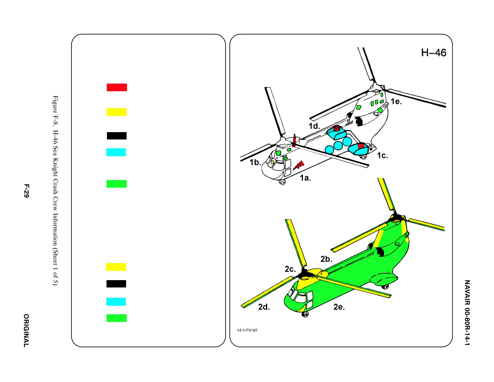
1.
GENERAL AIRCRAFT INFORMATION
a.
Armament
Two 50 cal or
ąM-60 Guns
Chaff/Flares (CH-46E)
b.
Oxygen
A/C prior to 154045
ąTwo 295 in3 Bottles
ą(CH-46E)
c.
Battery
1
d.
Fuel
Internal 380 gal
Internal Auxiliary
ąThree Tanks
ą243 gal each
e.
Oil
Engine 13 gal
ą(CH-46E)
Hydraulic 5.77 gal
ą(CH-46E)
Transmission 9 gal
f.
Pneumatic
3000 PSI
ąSystem
2.
AIRFRAME MATERIALS
a. N/A
b. Other
ąFiberglass
c. Steel
d. Titanium
e. Aluminum
f. N/A
g. N/A
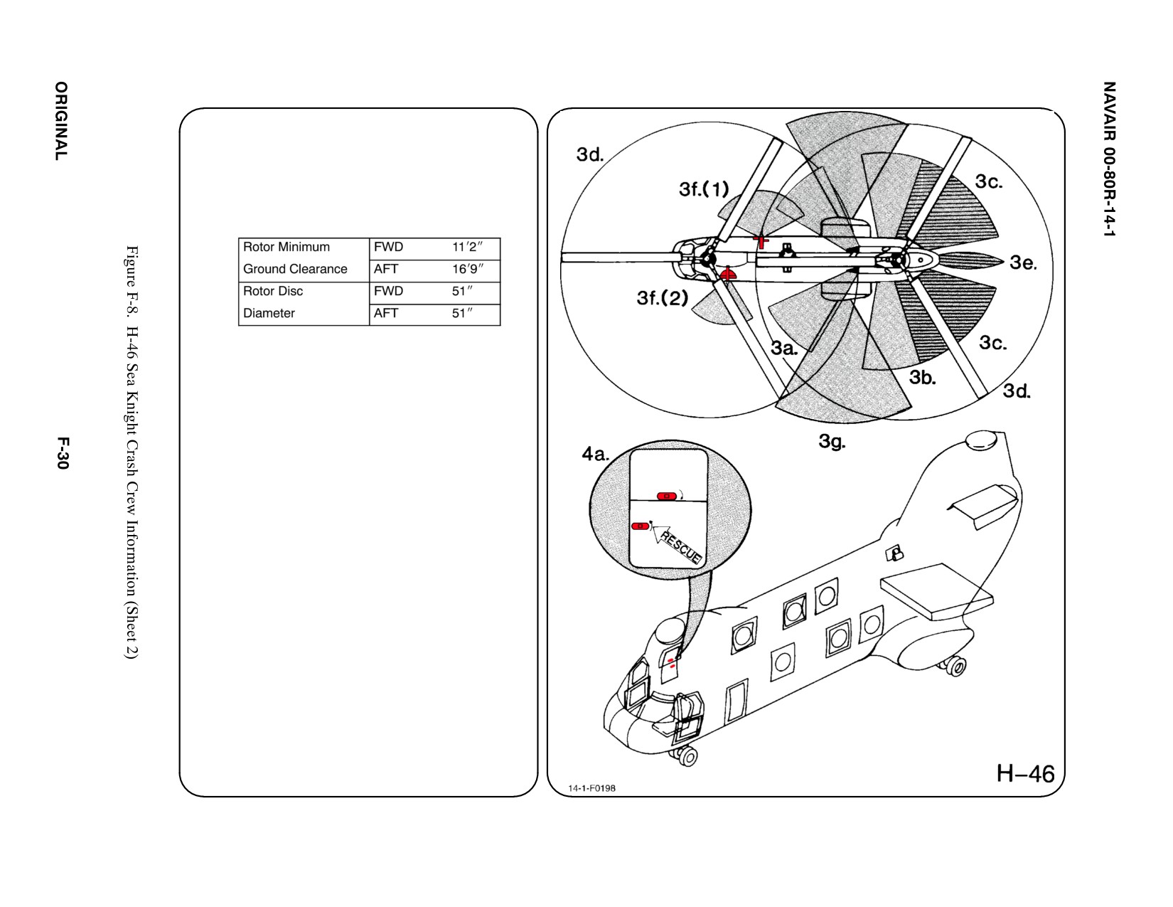
3. AIRCRAFT DANGER AREAS
a. Inlet Suction — 4i
b. Turbine Blade Failure
c. Engine Exhaust 12i
d. Rotors
e. APP Exhaust — 12i
f. Guns
(1) M-60 Guns
ą 62_ Pattern FWD
ą 65_ Pattern AFT
ą 44_ Below Sponson
(2) 50 cal Guns
ą 51_ Pattern FWD
ą 32_ Pattern AFT
ą 51_ Below Sponson
g. Chaff/Flares
4.
AIRCRAFT ENTRY
a. NORMAL ENTRY
Normal entry is through main cabin door on
RH side. The door has an upper and lower
door which operate separately. To open
upper portion, PUSH handle to expose,
TURN HANDLE CLOCKWISE, MOVE door
INWARD slightly and ROLL UP until the
uplock is engaged. The lower door opens
out and down. To open, PUSH handle,
TURN handle COUNTERCLOCKWISE and
PULL door OUT and DOWN.
b. N/A123
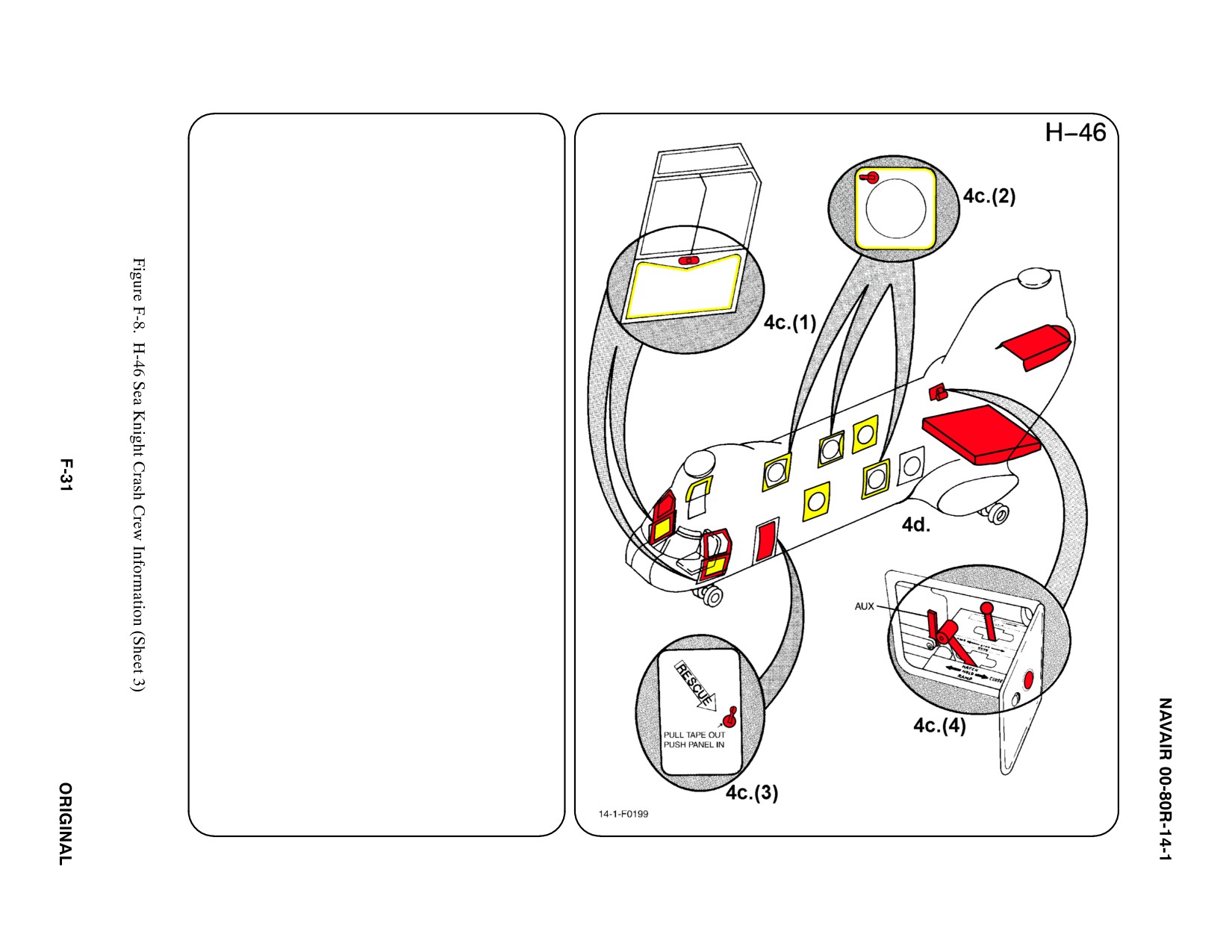
4.
AIRCRAFT ENTRY (CONT.) ab
c.
EMERGENCY ENTRY
Emergency entrance may be gained
through pilot/copilot jettison able windows,
three fuselage windows, the emergency
access hatch, and the cargo ramp/hatch.
(1)
To open pilot/copilot's jettison able
window PUSH handle, TURN handle
CLOCKWISE and PULL.
(2)
Three windows, two on RH side and one
on LH side are marked RESCUE. To
open, PULL tape OUT (upper LH corner
of window) the PUSH panel INWARD.
(3)
To open the Emergency Access Hatch
(CH-46E LH side), also marked
RESCUE, PULL tape OUT and PUSH
panel INWARD.
(4)
The Cargo Ramp/Hatch Controls are
located on RH side, above stub wing
(rear). To access controls, PUSH button
on access door. The system consists of
three control levers. With hydraulic
pressure, actuate both ramp and hatch
by PUSHING Ramp Control Handle and
Cargo Hatch Control Handle AFT.
Without hydraulic pressure, only ramp
will operate. To lower ramp, PUSH
Ramp Control Handle AFT then PUSH
Ramp Auxiliary Control Handle AFT.
d. FORCED ENTRY
Windows are made of acrylic plastic and
may be cut or broken. Areas marked on
fuselage CUT HERE also may be cut out.
CUT along window frames and marked
fuselage areas only.
5.
N/A
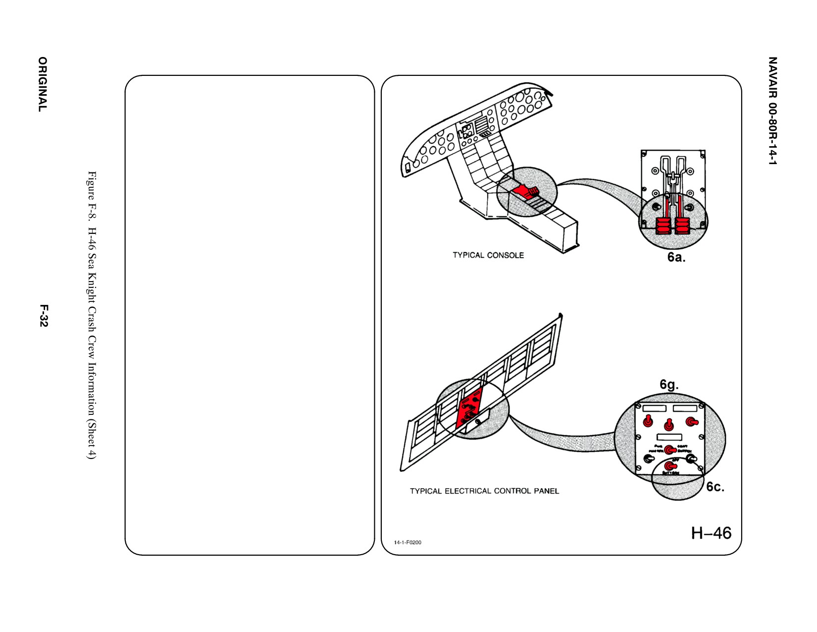
6.
ENGINE SHUTDOWN
a.
CONDITION LEVERS
PULL Condition Levers, fully AFT to STOP
position.
b. N/A
c.
BATTERY SWITCH
Deactivate electrical system by PLACING
Battery Switch in the OFF position. The
electrical power control panel is located in
the overhead console.
d. N/A
e.
N/A
f.
N/A
g. APU
PLACE Power Off Switch in OFF position.
PLACE Power Control Master Switch in
OFF position. PLACE APU Switch in STOP
position.
Note
Fire handles may be pulled to secure fuel and oil
to engines.
7. BATTERY
The battery is located in the left wheelwell.
a. N/A
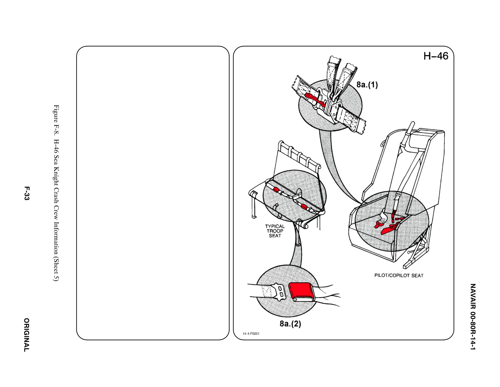
8. CREW RELEASE
The pilot and copilot are attached to the seats
by shoulder harnesses secured to lap belts
with quick disconnect buckles. Passengers
and crew-members have lap belts only.
a. PERSONNEL SERVICE, QUICK
DISCONNECT
(1) LIFT quick disconnect lever to release
shoulder harnesses and lap belt.
(2) TROOP: LIFT buckle cover to release
lap belt (airline type).
b. N/A
c. N/A
d. N/A
SPECIAL TOOLS/EQUIPMENT
Power Rescue Saw
Crash Axe
1.
GENERAL AIRCRAFT IN FORMATION
a. Armament
Two 50 cal Guns
Chaff/Flares
Two External Fuel
ąTank Ejector
ąCartridges
b. N/A
c. N/A
d. Fuel
Internal 638 gal
External 1300 gal
e. Oil
Engines 8.04 gal
Hydraulic 6.5 gal
Transmission 22.5 gal
f. Pneumatic
3000 PSI
ąSystem
2.
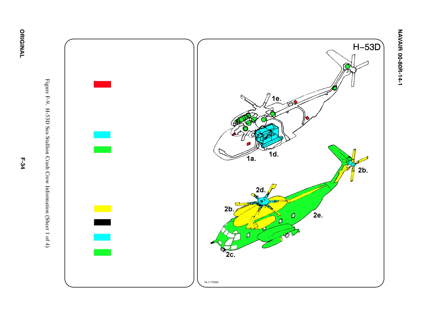
AIRFRAME MATERIALS
a. N/A
b. Other
ąFiberglass
c. Steel
d. Titanium
e. Aluminum
f. N/A
g. N/A
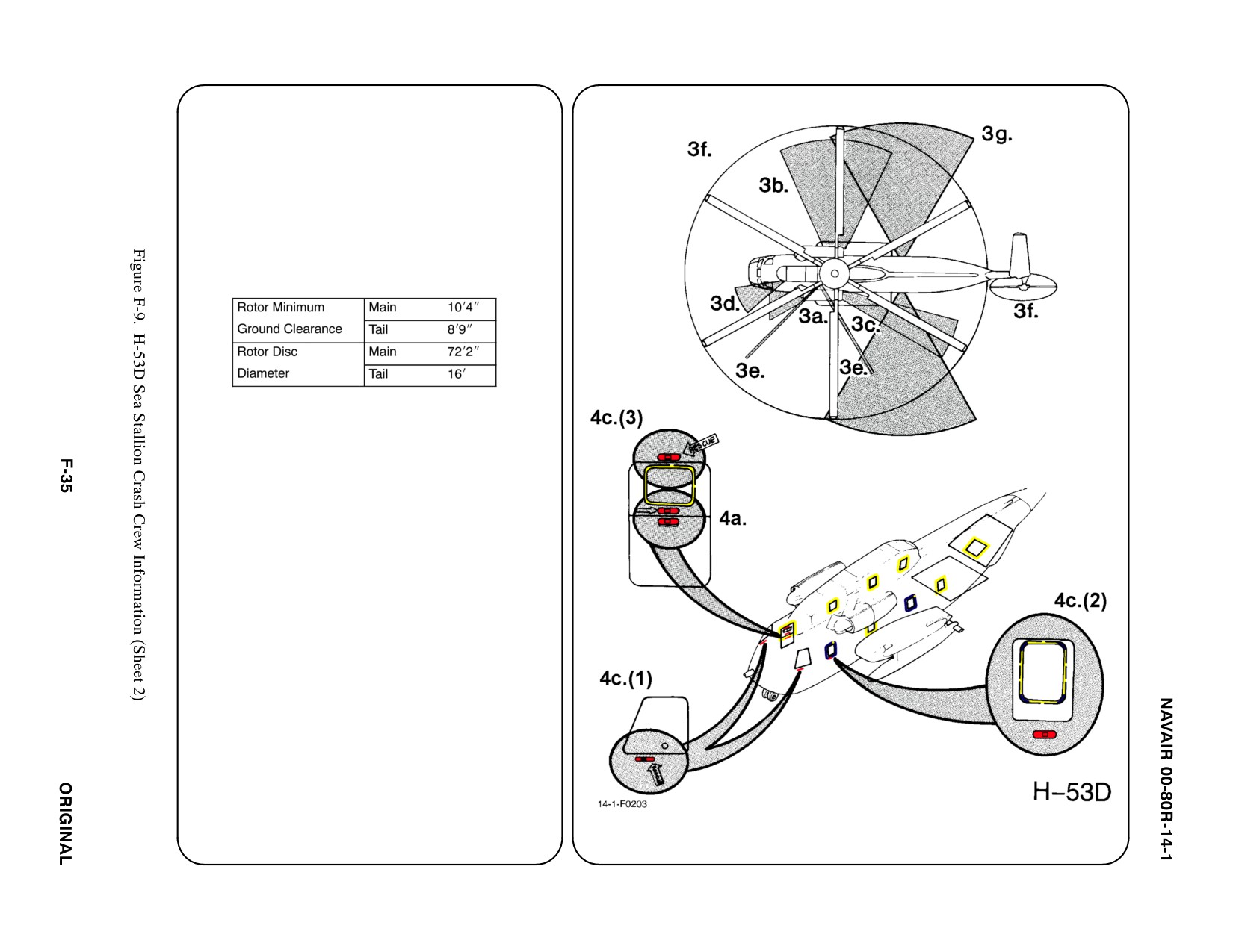
3. AIRCRAFT DANGER AREAS
a. Inlet Suction — 8i
b. Turbine Blade Failure — 300i
c. Engine Exhaust — 30i
d. APP and Heater Exhaust — 10i
e. Guns
66_ Pattern FWD
66_ Pattern AFT
30_ Below Sponson
f. Rotors
g. Chaff/Flares
4.
AIRCRAFT ENTRY
a.
NORMAL ENTRY
The upper half of Personnel Door may be
opened from outside by PRESSING button and
TURNING handle COUNTERCLOCKWISE.
PUSH upper half UP to cabin ceiling and
TURN handle COUNTERCLOCKWISE to lock
in OPEN position. The lower half of Personnel
Door opens DOWN. PUSH button, TURN
handle COUNTERCLOCKWISE and PULL.
b. N/A
c.
EMERGENCY ENTRY
(1) The pilot/copilot's compartment window
may be opened by PRESSING button and
TURNING handle.
(2) The Cabin Emergency Escape Hatch (left
FWD side of cabin) may be opened by
PRESSING button, TURNING handle
COUNTERCLOCKWISE and PUSHING
INWARD.
(3) Upper half of Personnel Door may be
jettisoned, TURN handle and PULL
OUTWARD. 123
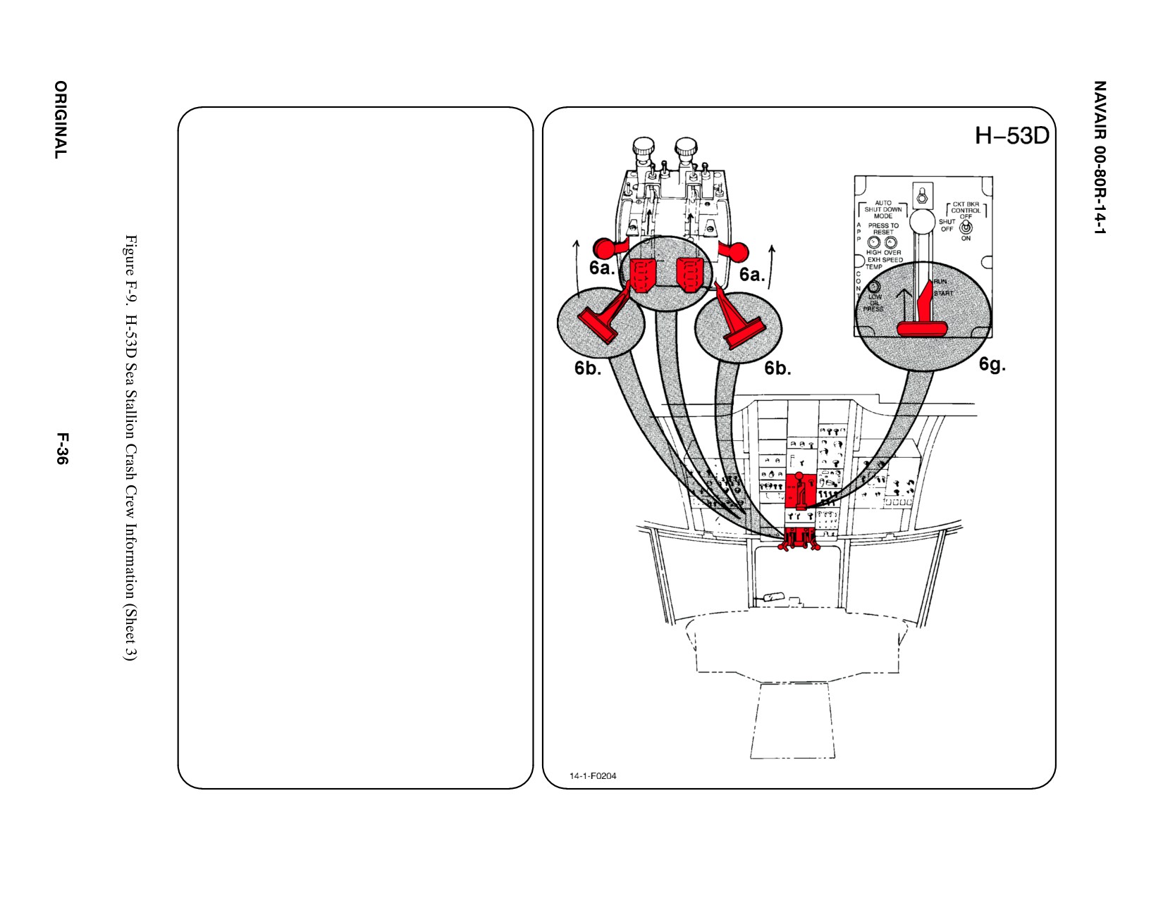
4.
AIRCRAFT ENTRY (CONT.)
a. FORCED ENTRY
Windows are made of acrylic plastic
and may be cut or broken. Areas
marked on fuselage CUT HERE also
may be cut for access. CUT along
window frames and marked fuselage
areas only.
5.
N/A
6.
ENGINE SHUTDOWN
Engine may be shut down by speed
control and fuel shutoff or an alternate
method by the emergency T-handle.
a. ENGINE SPEED CONTROL LEVERS
PULL Engine Speed Control Levers
fully AFT to SHUTOFF position.
b. ENGINE EMERGENCY T-HANDLES
PULL Engine Emergency T-Handles
fully AFT (fuel valves will close).
Note
If only emergency T-handles are used, the
engines will continue to run for up to
2 minutes before fuel starvation effects a
shutdown.
c. N/A
d. N/A
e. N/A
f. N/A
g. AUXILIARY POWER PLANT (APP)
Pull APP Control Lever fully AFT if the
system is operating.
7. N/A
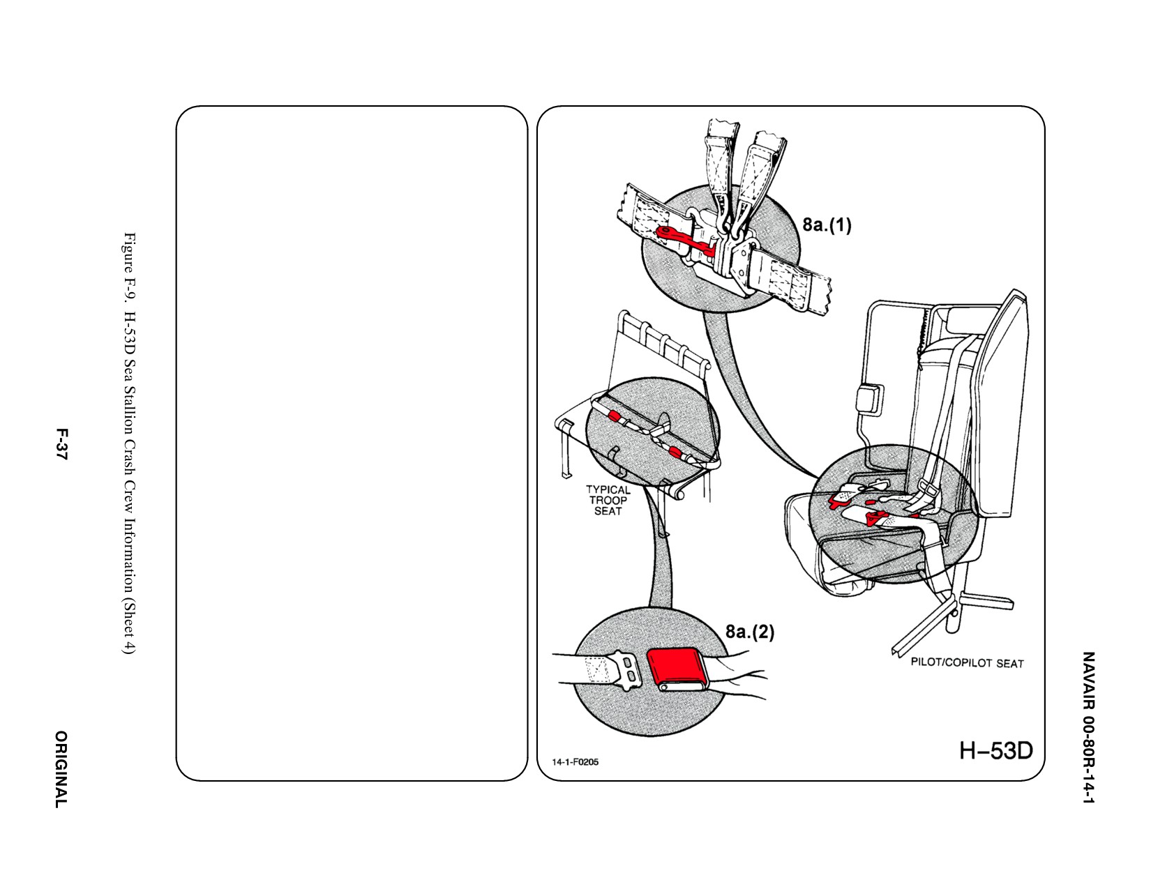
8. CREW RELEASE
The pilot and copilot are attached to the seats
by shoulder harnesses secured to a lap belt
equipped with a quick disconnect buckle.
Passengers and crewmembers have lap belts
only.
a. PERSONNEL SERVICE, QUICK
DISCONNECT
(1) LIFT quick disconnect lever to release
shoulder harnesses and lap belt.
(2) TROOP: LIFT buckle cover to release
lap belt (airline type).
b. N/A
c. N/A
d. N/A
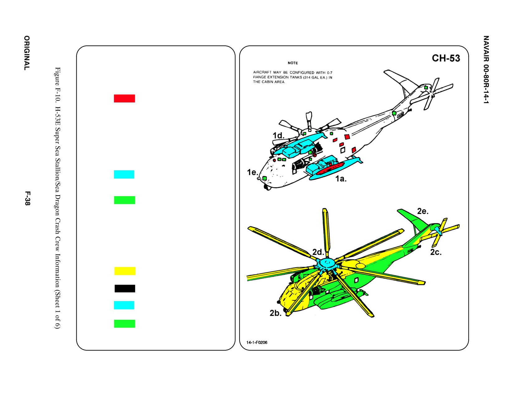
SPECIAL TOOLS/EQUIPMENT
Power Rescue Saw
Crash Axe
1.
GENERAL AIRCRAFT INFORMATION
a. Armament
Two 50 cal or M-60
ąGuns
Mines
Flares
Pylon Ejector
ąCartridges
Rescue Hoist
b. N/A
c. N/A
d. Fuel
Internal 977 gal
External 1300 gal
e. Oil
Engine 11.67 gal
Hydraulic 6.5 gal
Transmission 24 gal
f. Pneumatic
3000 PSI
ąSystem
2.
AIRFRAME MATERIALS
a. N/A
b. Other
ąFiberglass/Kevlar
c. Steel
d. Titanium
e. Aluminum
f. N/A
g. N/A
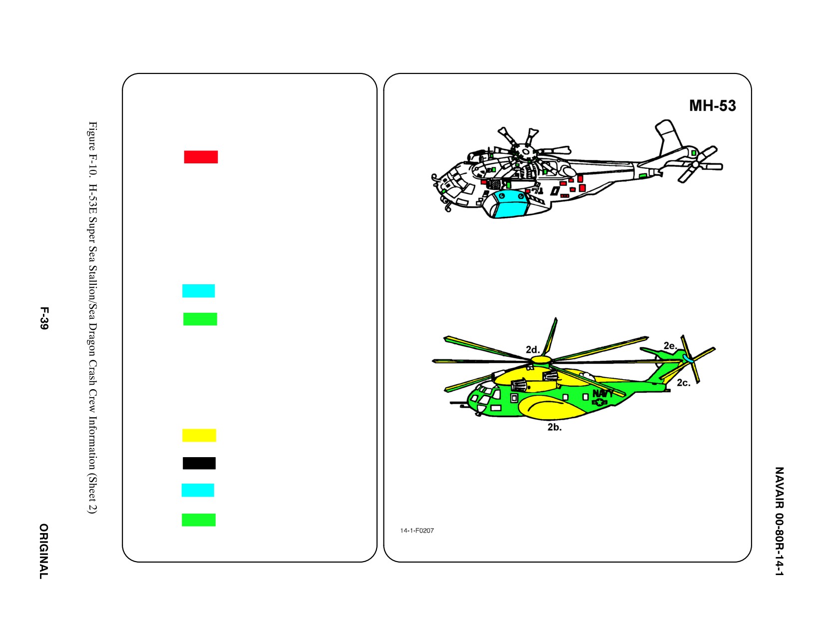
SPECIAL TOOLS/EQUIPMENT
Power Rescue Saw
Crash Axe
1.
GENERAL AIRCRAFT INFORMATION
a. Armament
Two 50 cal Guns
Explosive Cutters
Flares
Rescue Hoist
Single Point Cargo
ąHook
AMCM Guillotine
ąCartridges
b. N/A
c. N/A
d. Fuel
Internal 3212 gal
e. Oil
Engine 11.67 gal
Hydraulic 9.3 gal
Transmission 24 gal
f. Pneumatic
3000 PSI
ąSystem
2.
AIRFRAME MATERIALS
a. N/A
b. Other
ąFiberglass/Kevlar
c. Steel
d. Titanium
e. Aluminum
f. N/A
g. N/A
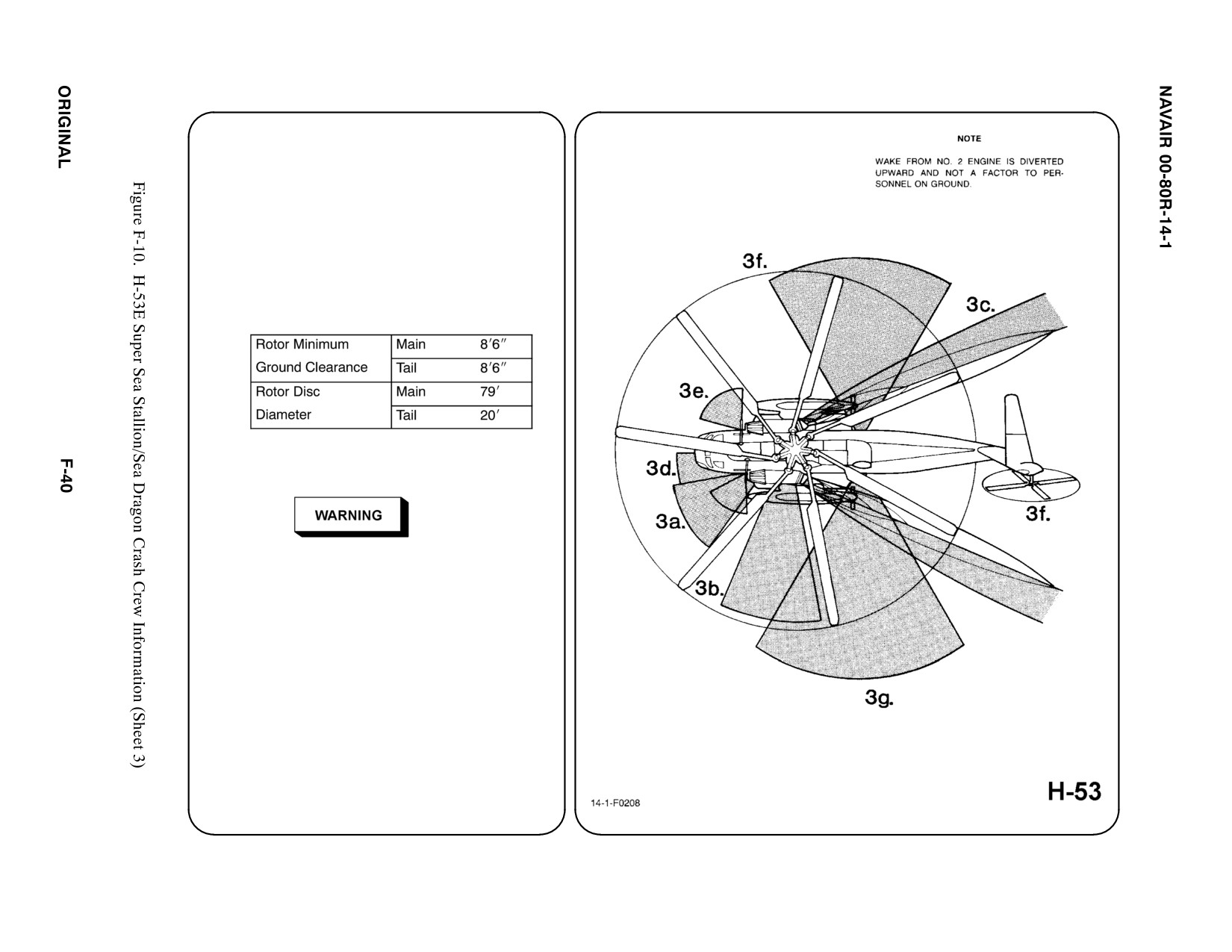
3. AIRCRAFT DANGER AREAS
a. Inlet Suction — 8i
b. Turbine Blade Failure — 300i
c. Engine Exhaust — 60i
d. APP Heat Exhaust — 10i
e. Guns
60_ Pattern FWD
66_ Pattern AFT
30_ Below Sponson
f. Rotors
g. Chaff/Flares
h. Static Electrical Charge
Contact with a hovering C/MH-53E may
result in injury or death of ground
personnel. The C/MH-53E generates an
extreme static electrical charge while in
flight; prior to physical contact with any part
of a hovering helicopter, the helicopter shall
be properly grounded.
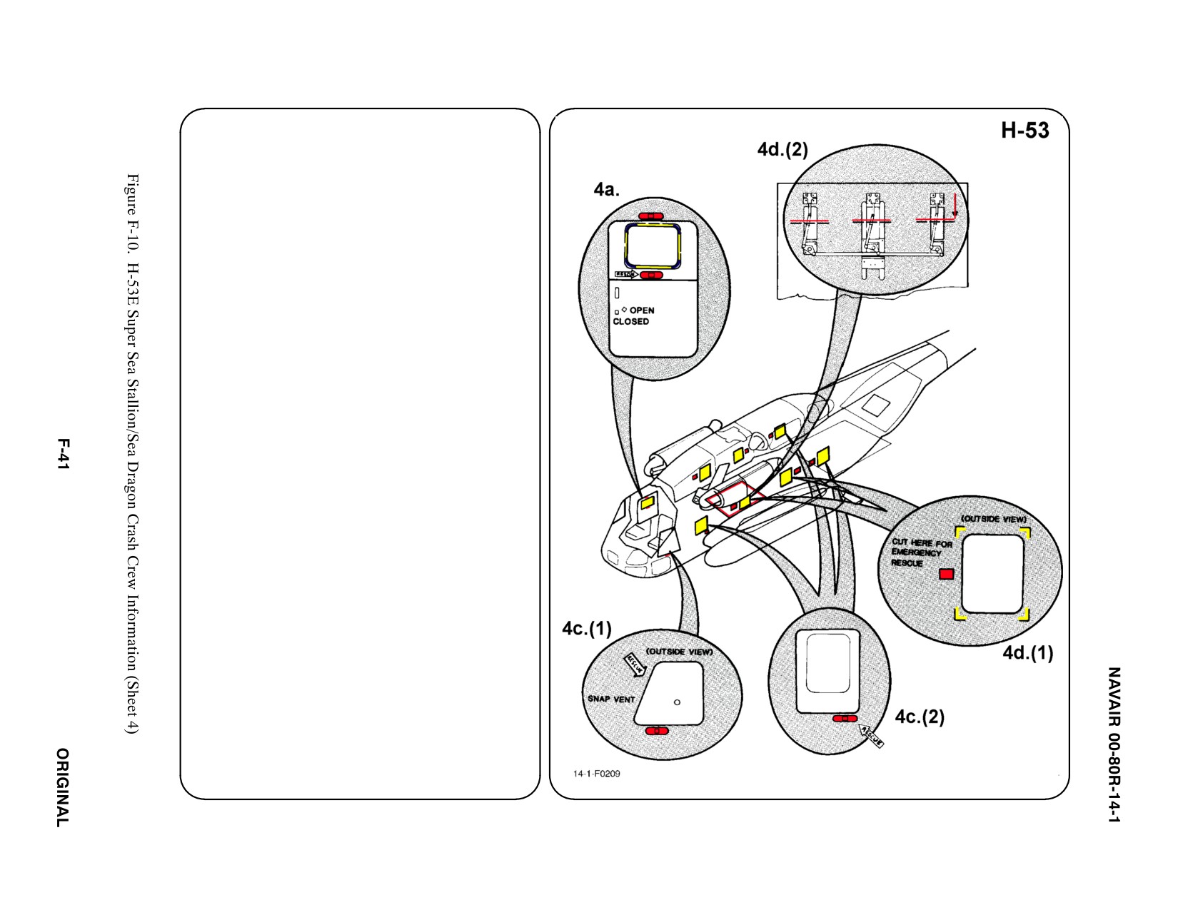
4.
AIRCRAFT ENTRY
a.
NORMAL ENTRY
The upper half of Personnel Door may be
opened from outside by PRESSING button
and TURNING handle
COUNTERCLOCKWISE. PUSH upper half
UP to cabin ceiling and TURN handle
COUNTERCLOCKWISE to lock in OPEN
position. The lower half of Personnel Door
swings IN to RIGHT. PUSH button, TURN
handle COUNTERCLOCKWISE and PUSH.
b. N/A
c.
EMERGENCY ENTRY
(1) The pilot/copilot's compartment window
may be opened. PRESS button and
TURN handle.
(2) The Cabin Emergency Escape Hatch
(left FWD cabin) may be opened.
PRESS button, TURN handle
COUNTERCLOCKWISE and PUSH
INWARD.
d. FORCED ENTRY
(1) Windows are made of acrylic plastic and
may be cut or broken. Areas marked on
fuselage CUT HERE also may be cut for
access. CUT along window frames and
marked fuselage areas only.
(2) All CH-53Es have a door in the center of
the cabin floor. The door has no external
handle, however, entry may be gained
by CUTTING three lock bolts. Once cut,
bolts may be PULLED OUT allowing
door to be PUSHED INWARD.
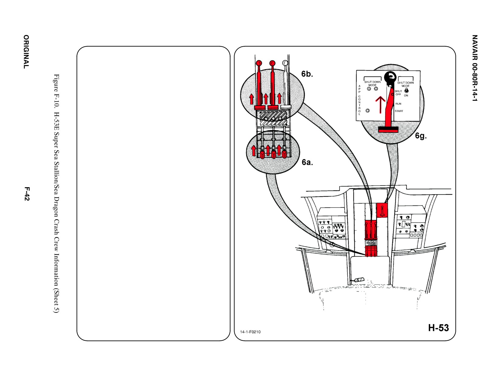
5. N/A
6. ENGINE SHUTDOWN
a. ENGINE SPEED CONTROL LEVERS
PULL Engine Speed Control Levers
DOWN and fully AFT to SHUT OFF
position.
b. ENGINE EMERGENCY T-HANDLES
PULL Engine Emergency T-Handles fully
AFT (fuel valves will close).
c. N/A
d. N/A
e. N/A
f. N/A
g. AUXILIARY POWER PLANT (APP)
PULL APP Control Lever fully AFT if
system is operating.
7. N/A
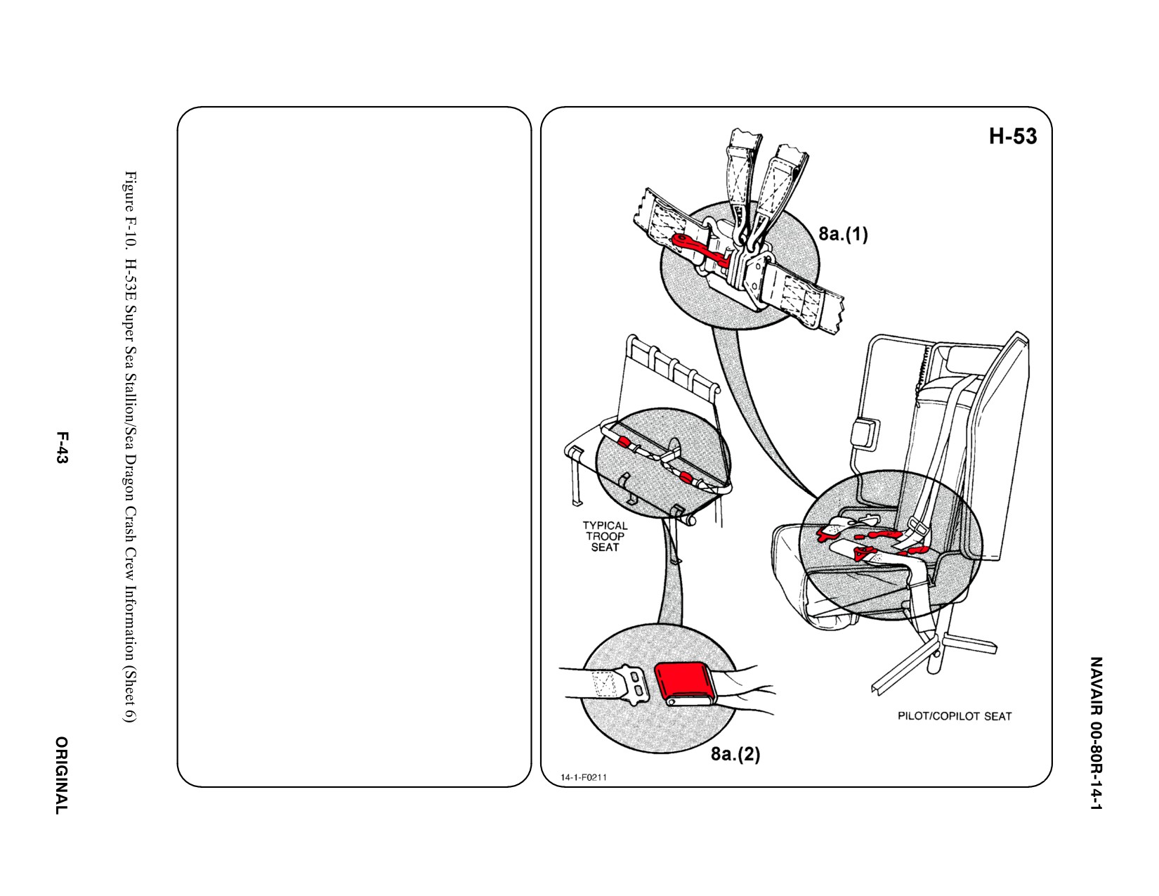
8. CREW RELEASE
The pilot and copilot are attached to the
seats by shoulder harnesses secured to
lap belts equipped with quick disconnect
buckles. Passengers and crewmembers
have lap belts only.
a. PERSONNEL SERVICE, QUICK
DISCONNECT
(1) LIFT quick disconnect lever to
release shoulder harnesses and
lap belt.
(2) TROOP: LIFT buckle cover to
release lap belt (airline type).
b. N/A
c. N/A
d. N/A
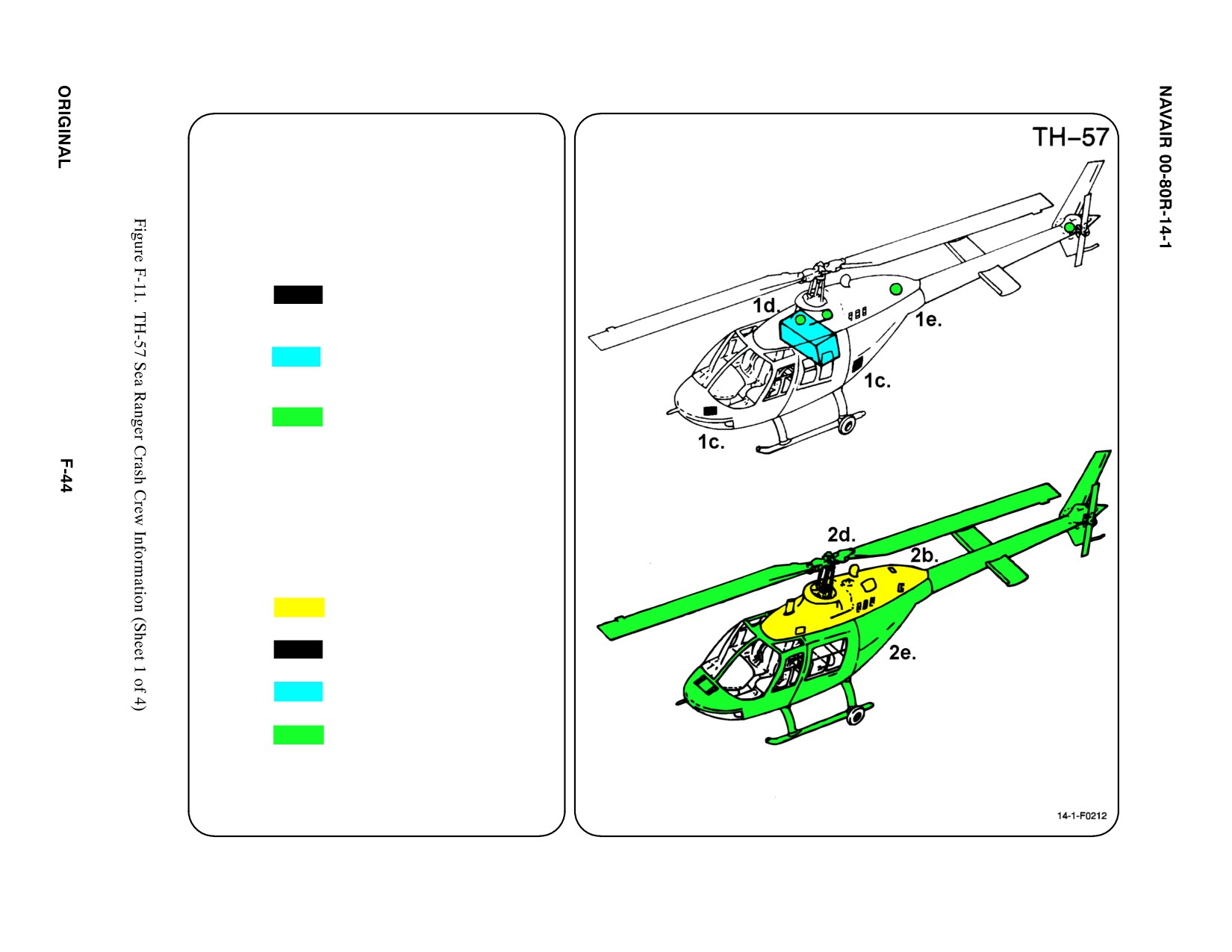
SPECIAL TOOLS/EQUIPMENT
Power Rescue Saw
Crash Axe
1. GENERAL AIRCRAFT INFORMATION
a. N/A
b. N/A
c. Battery
1 TH-57B
2 TH-57C
d. Fuel
91 gal
e. Oil
Engine 5.5 qts
Hydraulic 1.0 pt
Transmission 5.0 qts
T/R Gearbox .38 pt
f. Pneumatic
650 PSI
ąSystem
2. AIRFRAME MATERIALS
a. N/A
b. Other
Fiberglass
c. Steel
d. Titanium
e. Aluminum
f. N/A
g. N/A
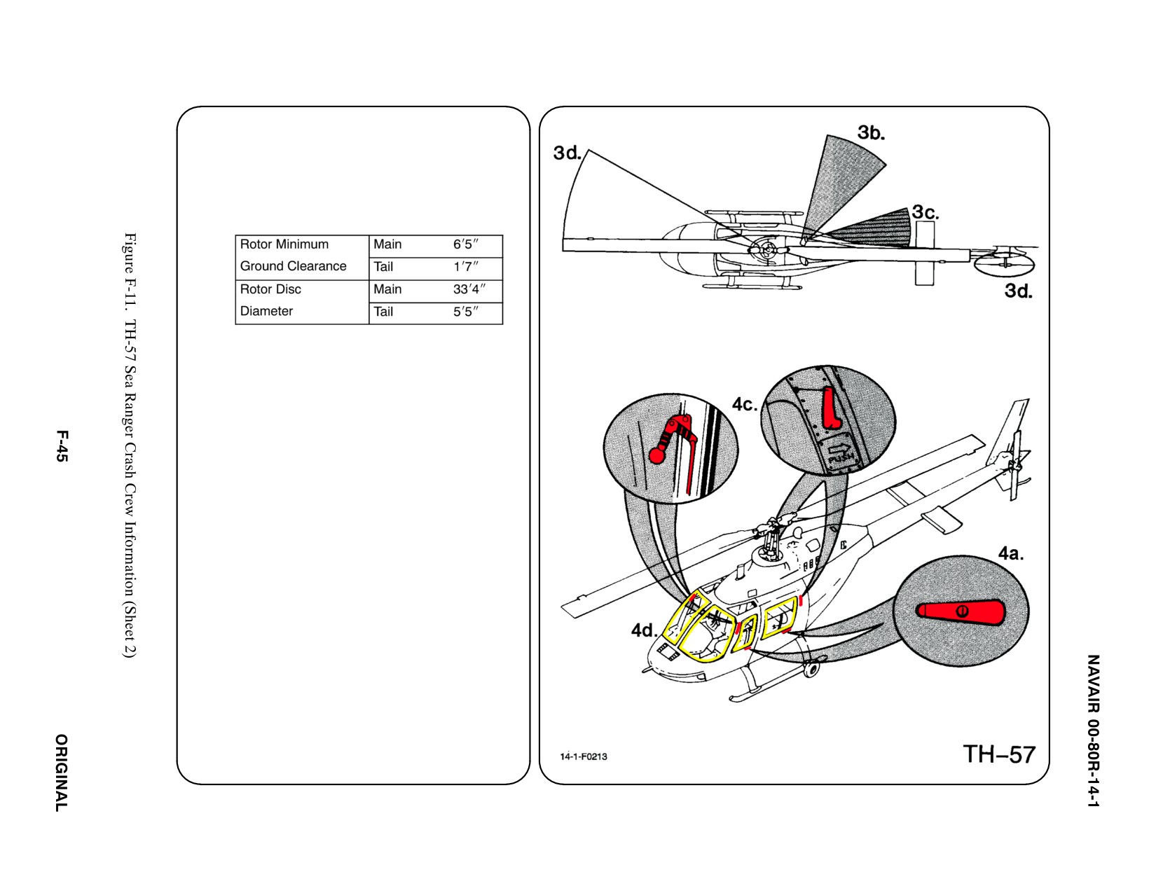
3. AIRCRAFT DANGER AREAS
a. Inlet Suction — Unknown
b. Turbine Blade Failure — 300i
c. Engine Exhaust — 20i
d. Rotors
4. AIRCRAFT ENTRY
a. NORMAL ENTRY
The Cockpit and Cabin Doors on both
sides of aircraft, are used for normal entry.
PULL door handle OUT, PUSH door open.
b. N/A
c. EMERGENCY ENTRY
Access to the Jettison Handles from the
outside can be gained by BREAKING the
plexiglass windows, REACHING IN and
PULLING Jettison Handles.
Note
The jettison handles are installed on TH-57C
aircraft only.
d. FORCED ENTRY
Windows are made of acrylic plastic and
may be cut with power rescue saw or crash
axe. CUT along window frames.
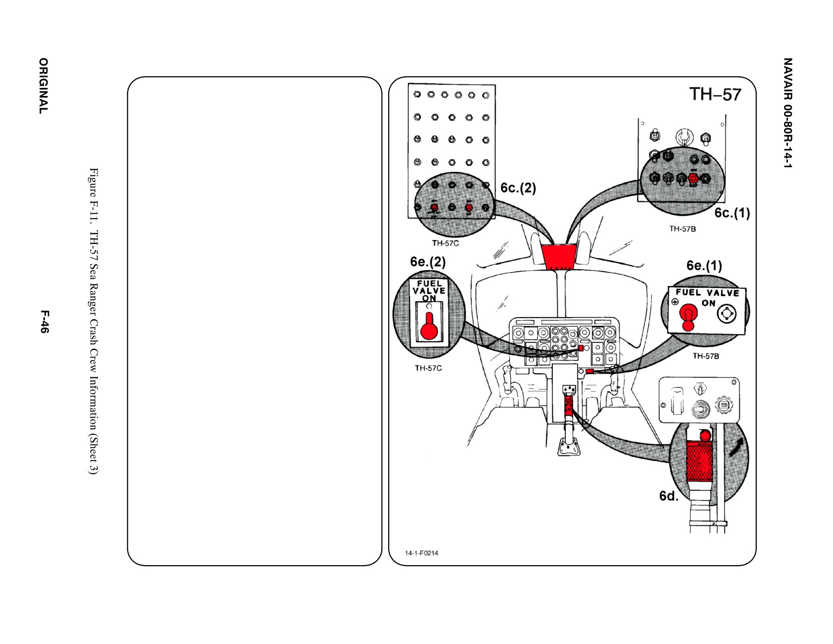
5.
N/A
6.
ENGINE SHUTDOWN
a.
N/A
b. N/A
c.
BATTERY SWITCH(ES)
d. THROTTLES
ROTATE Throttle Twist Grip CLOCKWISE.
DEPRESS Idle Rel Button and continue to
ROTATE to Shutoff/STOP position.
e.
FUEL VALVE SWITCH
PLACE fuel Valve Switch in OFF position.
(1) TH-57B, located on RH side of pedestal
instrument panel.
(2) TH-57C, located on instrument panel.
(3) TH-57B, PLACE Battery Switch in OFF
position.
(4) TH-57C, PLACE Battery Switch and
Standby Battery Switch in OFF position.
f.
N/A
g. N/A
7.
BATTERIES
The FWD battery is located in the nose
section, accessible through a hinged door. The
AFT battery in the TH-57C is located in the
AFT portion of the baggage compartment,
accessible through the baggage door on the
LH side of aircraft.
a. N/A
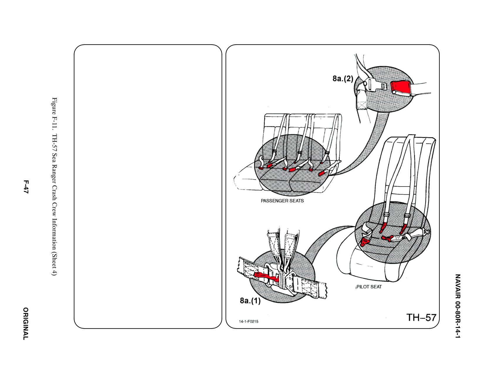
8. CREW RELEASE
The pilot and copilot are attached to the seats
with shoulder harnesses and a lap belt
equipped with a quick disconnect buckle.
Passengers and crewmembers have a lap
belt and a fixed shoulder harness.
a. PERSONNEL SERVICE, QUICK
DISCONNECT
Note
Before releasing the lap belt/shoulder harness
from the pilot/copilot, disconnect the helmet
cord.
(1) LIFT quick disconnect lever to release
shoulder harnesses and lap belt.
(2)
(PASSENGER: LIFT buckle cover to
release lap belt (airline type).
b. N/A
c. N/A
d. N/A
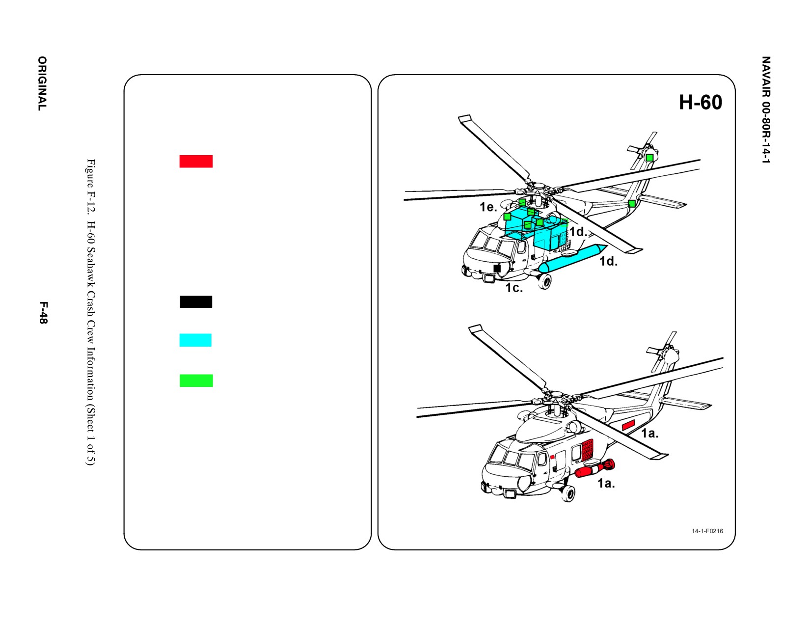
SPECIAL TOOLS/EQUIPMENT
Power Rescue Saw
Crash Axe
1. GENERAL AIRCRAFT INFORMATION
a. Armament
Torpedoes
Sonobuoy Launcher
GAU-16A
MK-25 MLM
MK-39
MK-58 MLM
MK-64
MK-84 SUS
MD240D
Hellfire Missle
b. N/A
c. Battery
1
d. Fuel
Internal 590 gal
External 120 gal
e. Oil
Engine 3.8 gal
Hydraulic 3.9 qt
Transmission 8.15 gal
f. Pneumatic
Two Systems
ąSystem
ą3200 PSI
ą1250 PSI
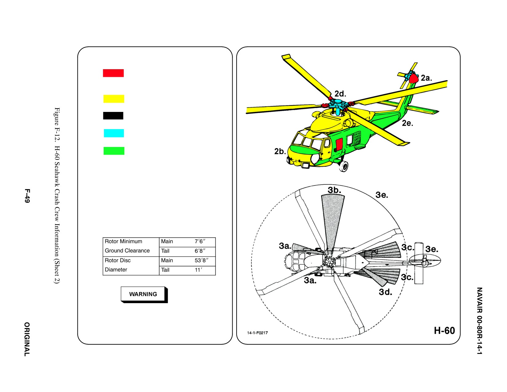
2. AIRFRAME MATERIALS
a. Graphite Epoxy
b. Other
Fiberglass/Magnesium/Kevlar
c. Steel
d. Titanium
e. Aluminum
f. N/A
g. N/A
3. AIRCRAFT DANGER AREAS
a. Inlet Suction — 4i
b. Turbine Blade Failure — 300i
c. Engine Exhaust — 30i
d. APU Exhaust — 4i
e. Rotors
Tip of rotor blade may drop as low as 4 feet
from ground when turning.
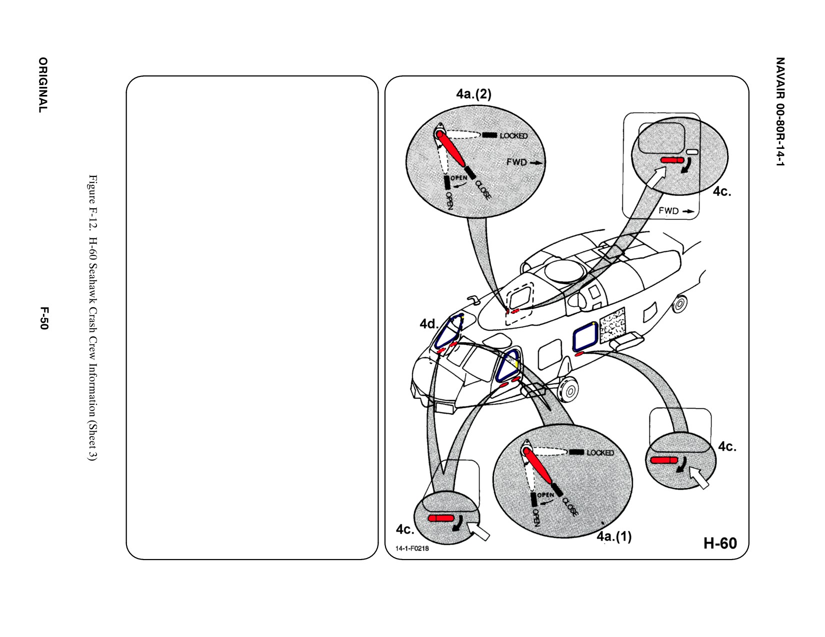
4.
AIRCRAFT ENTRY
a. NORMAL ENTRY
(1) Enter the pilot/ATO area through hinged
door on each side of cockpit. PULL
handle DOWN to open.
(2) A sliding door on RH side of fuselage
provides access to the cabin. PUSH to
release handle and TURN DOWN to
open.
b. N/A
c. EMERGENCY ENTRY
The pilot and ATO windows, cabin door
window and cabin window may be jettisoned
by operating the Emergency Release Handle
and PULLING window OUT.
d. FORCED ENTRY
If main entrances are jammed or inoperable,
CUT around pilot, ATO, and SO windows.
5.
N/A
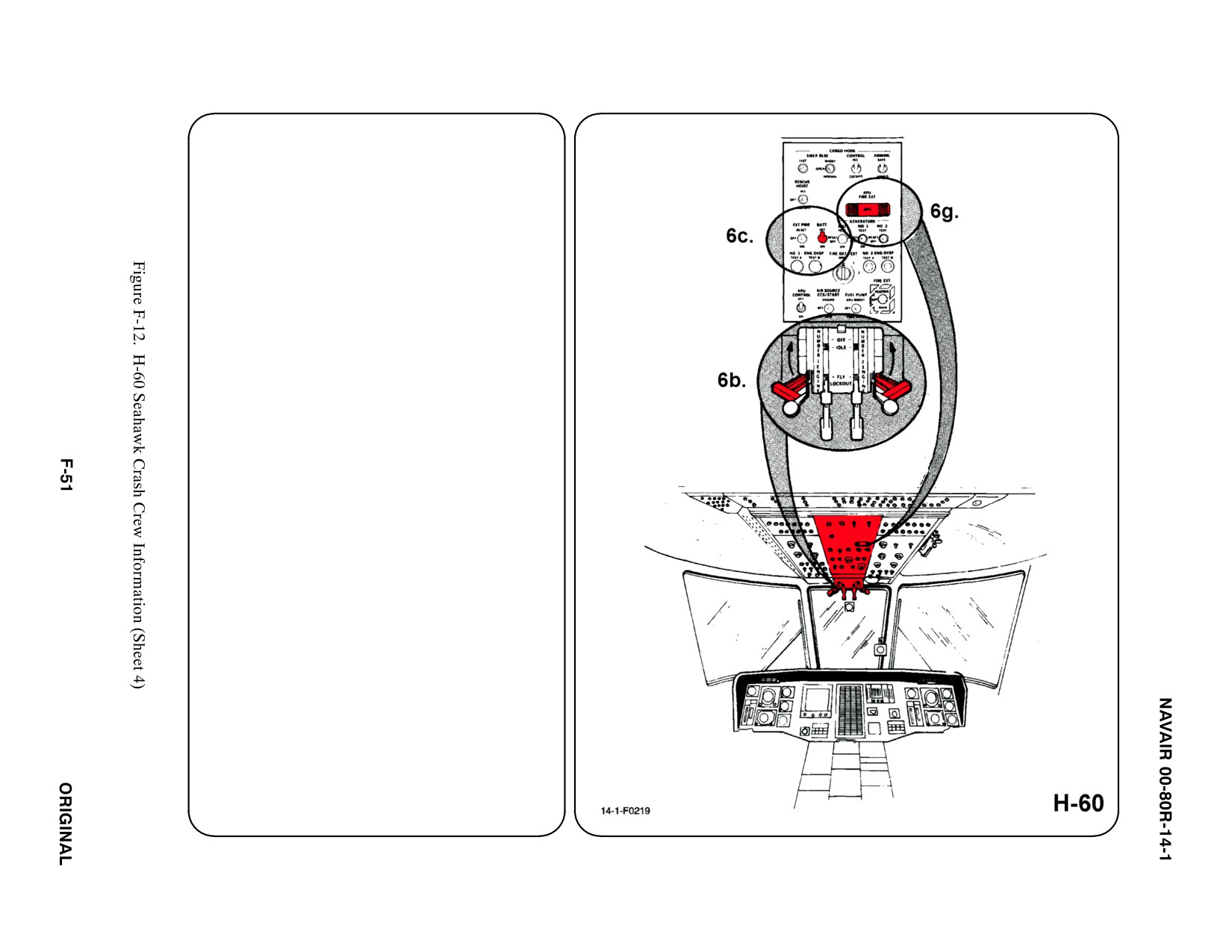
6.
ENGINE SHUTDOWN
a. N/A
b. EMERGENCY T-HANDLES
PULL both Engine Emergency T-Handles
AFT to OFF position.
c. BATTERY SWITCH
PLACE Battery Switch in OFF position.
d. N/A
e. N/A
f. N/A
g. AUXILIARY POWER UNIT (APU)
PULL APU Fire Extinguisher T-Handle
(required if APU operating).
7.
BATTERY
To further deactivate the electrical system,
disconnect battery quick disconnect fitting.
Battery is located in ATO seat well.
a. N/A
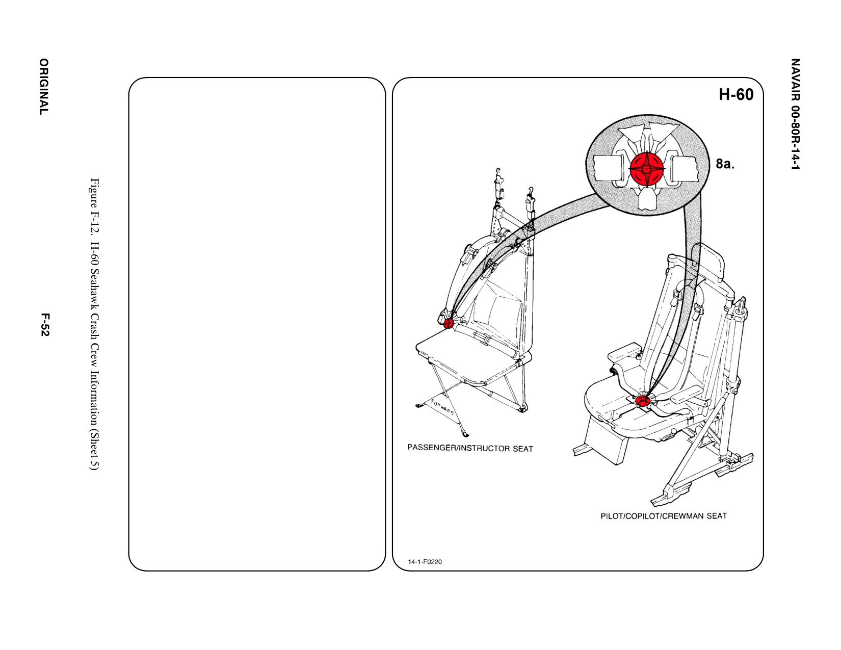
8. CREW RELEASE
The pilot, copilot, crewman, and
instructor/passenger are attached to the seats
by a complete lap belt and dual torso-restraint
shoulder harness attached to a rotary release
buckle.
a. PERSONNEL SERVICE, QUICK
DISCONNECT
ROTATE Rotary Release Buckle in either
direction, to release shoulder harnesses and
lap belt.
b. N/A
c. N/A
d. N/A
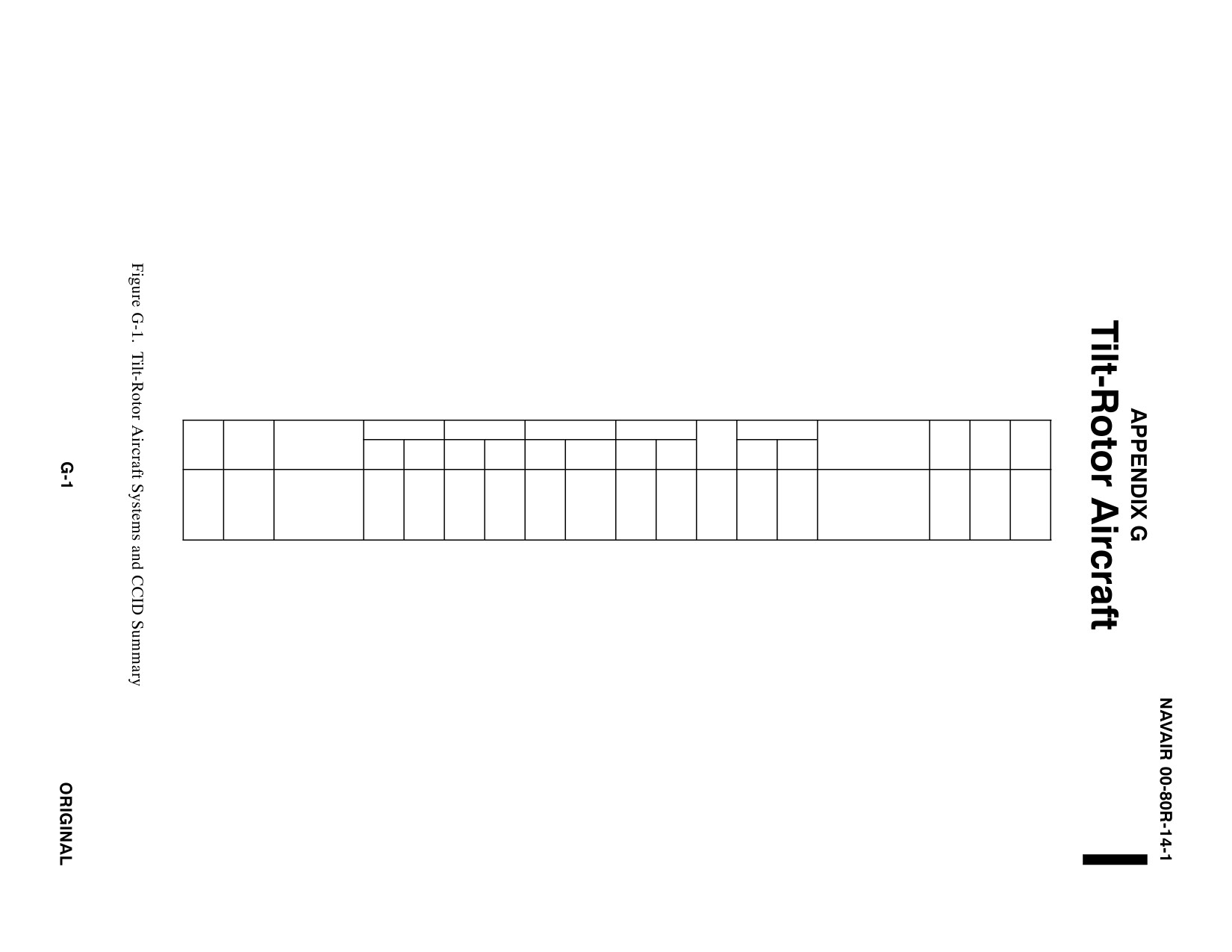
TILT-ROTOR AIRCRAFT SYSTEMS AND
CRASH CREW INFORMATION DIAGRAMS SUMMARY
FUEL (GAL)
OIL (GAL)
OXYGEN
PNEU SYS
ORDNANCE
AIRFRAME
FWD
FREE
EJEC
TYPE
NAME
MATERIALS
INT
EXT
ENG
HYD
LOX
BOTTL
GAS
AIR
GUN
FIRE
FALL
PYROTECHNICS
BTRY
SYS
SOB
MV-22B
OSPREY
ALUMINUM
1448
NONE
3.0
4.3
NONE
400L
N2
NONE
NONE
NONE
NONE
CHAFF/FLARES
1
NONE
27
TITANIUM STEEL
3000
ESCAPE
CARBON-EPOXY
PSI
WINDOWS/HATCHES
COMPOSITES
GLASS-EPOXY
COMPOSITES

NAVAIR 00-80R-14-1
APPENDIX BCDEFG
G.1
MV-22B LEFT/RIGHT CENTER, LEFT FORWARD CABIN FUSELAGE HATCH SEVERANCE
ASSEMBLY SOURCE DATA
Cabin fuselage hatches and overhead transparencies contain TLX. Serious
injury may result when activating these devices.
G.1.1 Function and Location
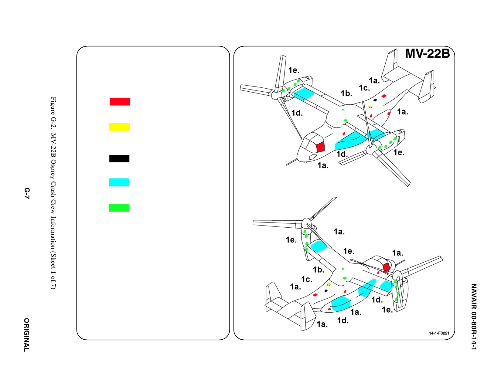
The left forward, left center, and right center hatch severance assemblies (see Figure G-2, Sheet 4) are used to
explosively sever its respective transparent fuselage skin material and are primarily intended to provide an escape
route for personnel.
G.1.2 Description
The Severance Assembly, are explosively loaded parts designed to cut the fuselage skin material at designated areas
of the fuselage along the hatch periphery when initiated by the system. The explosive part is composed of a piece
of lead tubing, shaped into a chevron shape and filled with high explosive material. The purpose of the chevron shape
is to focus more of the explosive reaction in one direction to form a cutting jet. The hatch assemblies are structurally
and functionally identical to the canopy severance assemblies except the explosive material itself is less powerful.
G.1.3 Operation
Functioning either the internal or external initiator starts a rapidly burning reaction in the TLX line end mated to the
initiator. This signal moves along the line rapidly from the initiator end (primer end) to the terminating end (high
explosive end), which is mated to the TLX connector. The terminating end of the TLX line initiates the other two
TLX lines mated to the connector. The signal then follows two different paths. The first path is the one to the severance
assembly. The TLX line (low energy by high explosive type) is mated to the connectors middle port and accepts the
signal from the initiator. This signal moves along the line rapidly from the low energy end to the high explosive end,
which is connected to the severance assembly. The high explosive end detonates which starts the detonation of the
explosive charge in the severance assembly. This detonation causes very high-pressure shock waves and metal
particles to be directed at, and strike the thin walled steel tube. The impact of the metal particles and the shock wave
cause the explosive material within the sleeve to detonate. This in turn will cause the detonation of the explosive in
the shaped lead tube. The detonation will be sent down the two ends of the tubing and will meet at a point nearly
opposite to where the manifold is located. The extremely rapid explosive reactions forms a focused jet of explosive
shock waves and heat which cuts through the plastic transparency graphite material creating an escape opening. The
opening is blocked however, by the troop seats mounted on the side of the troop compartment so the second signal
path is required to operate a system to release the troop seats from their mounting racks.
The second path the signal follows is to the thruster assembly, which is used to activate the troop seat release
mechanism and can be initiated only from the internal initiator.
The Cabin Fuselage Hatch Severance Assembly will operate satisfactorily with a temperature range of -54 to +93_C.
G.2
MV-22B OVERHEAD CABIN FUSELAGE HATCH SEVERANCE ASSEMBLY SOURCE DATA
G.2.1 Function and Location
The overhead hatch severance assembly (see Figure G-2, Sheet 4) is used to explosively sever the overhead escape
hatch and is primarily intended to provide an escape route for troop member or passenger if the aircraft has come to
rest on its side.
ORIGINAL
G-2

NAVAIR 00-80R-14-1
G.2.2 Description
The severance assembly, is a explosively loaded part designed to cut the fuselage skin material along the hatch
periphery when initiated by the system. The explosive part is composed of a piece of lead tubing, shaped into a
chevron shape and filled with high explosive material. The purpose of the chevron shape is to focus more of the
explosive reaction in one direction to form a cutting jet. The overhead hatch severance assembly is structurally and
functionally identical to the canopy severance assemblies except the explosive material itself is less powerful.
G.2.3 Operation
Functioning either the internal or external initiator starts a rapidly burning reaction in the TLX line end mated to the
initiator. This signal moves along the line rapidly from the initiator end to the terminating end, which is mated to the
severance assembly. The terminating end of the TLX line initiates the explosive charge in the severance assembly
which is specially shaped to focus most of the force outboard. This detonation causes very high-pressure shock waves
and metal particles to be directed at, and strike the thin walled steel tube. The impact of the metal particles and the
shock wave cause the explosive material within the sleeve to detonate. This in turn will cause the detonation of the
explosive in the shaped lead tube. The detonation will be sent down the two ends of the tubing and will meet at a
point nearly opposite to where the manifold is located. The extremely rapid explosive reactions forms a focused jet
of explosive shock waves and heat which cuts through the escape hatch material creating an escape opening.
The Cabin Fuselage Hatch Severance Assembly will operate satisfactorily with a temperature range of −54 to +93_C.
G.3
MV-22B EXTERNAL INITIATOR SOURCE DATA
G.3.1 Function
The External Initiator is used to start the pyrotechnic reaction of the TLX line.
G.3.2 Description
An External Initiator is used with the left and right Side Canopy, left forward, left and right Center Cabin Fuselage
Hatches, and the Overhead Fuselage Hatch. The External Initiator, is an inert mechanically actuated device. It is designed
to accept only the primer ended TLX lines. The initiator consists of a cylindrical housing containing a small handle,
approximately ten feet of thin steel cable and an initiator body. The external initiators are mounted flush to the fuselage
skin of the aircraft. No ground safety device is used for this initiator assembly; it is always at the ready position.
G.3.3 Operation
The external initiator assembly is operated by first arming the initiator and functioning it. Arming is accomplished
by depressing the red colored arming button with 6 to 12 pounds of force. Pushing the arming button allows the
retaining pin (three each) to be withdrawn inside the handle. This allows the initiator handle to deploy from the
initiator housing approximately 1 inch. The large spring in the base of the housing pushes the handle out of the
housing until the handle is stopped by the lockout pins. At this point the handle can be replaced in the ready position
by pushing the arming button, pushing the handle back into the housing and releasing the button. This action should
not be done on a routine basis as it could lead to accelerated wear of the initiator assembly.
The initiator is functioned by removing the handle from the housing and deploys a thin steel cable from the spool
on the inside of the handle as the operator moves away from the aircraft approximately ten feet. To function the system
the operator must pull on the initiator handle with 20 to 35 pounds of force. When the handle is pulled a firing pin
and a part called a sear is pulled back against a spring inside the initiator body. When the sear is pulled completely
out of the body the firing pin is released and driven in the opposite direction by the compressed spring. The firing
pin impacts the percussion primer cap, which is part of the TLX line. The impact to the primer cap starts the
pyrotechnic reaction in the TLX line.
The External Initiator will operate satisfactorily with a temperature range of −54 to +93_C.
G-3
ORIGINAL

NAVAIR 00-80R-14-1
G.4
MV-22B INTERNAL INITIATOR SOURCE DATA
G.4.1 Function
The Internal Initiator is used to start the pyrotechnic reaction of the TLX line.
G.4.2 Description
An Internal Initiator is used with the left and right Side Canopy, left forward, left and right Center Cabin Fuselage
Hatches, and the Overhead Fuselage Hatch. The Internal Initiator, is an inert mechanically actuated device. It is
designed to accept only the primer ended TLX lines. The initiator consists of a pull handle fitted with a push button
release, and a housing, which attaches to the aircraft structure. A safety pin with attached red flag with “REMOVE
BEFORE FLIGHT” is also included and can be installed into the initiator to prevent inadvertent operation.
G.4.3 Operation
To operate the internal initiator assembly the safety pin must be removed. Pushing the red arming button with 6 to
12 pounds of force arm the initiator. This action allows the retaining pin in the handle to withdraw from the catcher,
and the retaining balls in the arming sleeve to relax. The handle can now be removed from the housing.
The initiator is functioned by removing the handle from the housing and pulling with 20 to 35 pounds of force. The
handle will require approximately one and a half inches of travel to cause the initiator to function. When the handle
is pulled a firing pin and a part called a sear is pulled back against a spring inside the housing. When the sear is pulled
completely out of the housing the firing pin is released and the firing pin is driven in the opposite direction by the
compressed spring and impacts the percussion primer cap, which is part of the TLX line. The impact to the primer
cap starts the pyrotechnic reaction in the TLX line.
The Internal Initiator will operate satisfactorily with a temperature range of -54 to +93_C.
G.5
MV-22B SIDE CANOPY SEVERANCE ASSEMBLY SOURCE DATA
G.5.1 Function and Location
The left and right side canopy severance assemblies (see Figure G-2, Sheet 4) are used to explosively sever the side
cockpit transparencies and are primarily intended to provide an escape route for the pilot and copilot.
G.5.2 Description
The Severance Assembly, is an explosively loaded device parts designed to cut the side canopy transparency along
its periphery when initiated by the system. The explosive part is composed of a piece of lead tubing, shaped into a
chevron shape and filled with high explosive material. The purpose of the chevron shape is to focus more of the
explosive reaction in one direction to form a cutting jet.
G.5.3 Operation
Functioning either the internal or external initiator starts a rapidly burning reaction in the TLX line end mated to the
initiator. This signal moves along the line rapidly from the initiator end to the terminating end, which is mated to the
severance assembly. The terminating end of the TLX line initiates the explosive charge in the severance assembly.
This detonation causes very high-pressure shock waves and metal particles to be directed at, and strike the thin walled
steel tube. The impact of the metal particles and the shock wave cause the explosive material within the sleeve to
detonate. This in turn will cause the detonation of the explosive in the shaped lead tube. The detonation will be sent
down the two ends of the tubing and will meet at a point nearly opposite to where the manifold is located. The
ORIGINAL
G-4

NAVAIR 00-80R-14-1
extremely rapid explosive reactions forms a focused jet of explosive shock waves and heat which cuts through the
plastic transparency material creating an escape opening.
The Canopy Severance Assembly will operate satisfactorily with a temperature range of -54 to +93 _C.
G.6
MV-22B THRUSTER SOURCE DATA
G.6.1 Function
The Thruster Assembly is a restrained, one-time-use piston device used to release the troop seat release mechanism.
G.6.2 Description
The Thruster Assembly, is basically a piston contained in an aluminum housing. The Thruster Assembly itself does not
contain any explosive materials. A Thruster is used with the left forward, and the left and right Center Cabin Fuselage
Hatches.
G.6.3 Operation
The piston is restrained in its ready position by a pin. The Thruster will operate when a certain amount of gas pressure
pushes against the piston with sufficient force to break the pin. When the pin is broken the piston will travel
approximately 0.45 inch and will turn a cam on the troop seat release mechanism.
A hot gas-producing cartridge fitted to the mating TLX line develops the pressure source for the Thruster Assembly.
When this TLX line is initiated, hot gas is rapidly liberated by the cartridge and is directed into the piston chamber
where it pushes against the piston.
The Thruster will operate satisfactorily with a temperature range of -54 to +93_C.
G.7
MV-22B TLX LINE SOURCE DATA
G.7.1 Function
The Thin Line Explosive (TLX) transfer lines are used to initiate explosive cutting charges on the left/right cockpit
canopies, and cabin escape hatches 2LS3, 2RS3, 3CT1, and 2LS2.
G.7.2 Description
The TLX line is a pyrotechnic signal transmission line loaded with explosive and pyrotechnic materials. They are thin
plastic hollow tubes with a thin layer of explosive material coating the inside surface of the tube. The exterior of the tube
is covered with a flexible steel braid and then with a heat shrink plastic jacket. Three types of Transfer Lines (TLX) used
on the MV-22B aircraft include Primer-to-High Explosive (P-HE), High Explosive-to-Gas Generator (HE-GG), and High
Explosive-to-Low Explosive (HE-LE).
The Primer-to-High Explosive (P-HE), is used between the Internal/External initiators and Hatch Severance
Assemblies or Tee connectors installed either on the left/right cockpit canopies, or cabin escape hatches 2LS3, 2RS3,
3CT1, and 2LS2. The High Explosive-to-Gas Generator (HE-GG), is used between the Tee Connector and Thruster
Assembly on cabin escape hatches 2LS3, 2RS3, AND 2LS2. The High Explosive-to-Low Explosive (HE-LE), is
used between the Tee Connector and Hatch Severance Assembly for 2LS3, 2RS3, AND 2LS2.
G.7.3 Operation
When the Primer-to-High Explosive (P-HE) TLX line is ignited, the explosive material on the inner wall burns
rapidly (no explosive detonation occurs because there is very little material in any given area and the material is not
G-5
ORIGINAL

NAVAIR 00-80R-14-1
compacted) producing a hot gas shock wave that travels down the tube from one end to the other. The material that
is burned along the tube continually reinforces the shock wave. Special purpose end assemblies are attached to the
ends of the TLX lines. The primer is by high explosive type TLX, one end is fitted with a primer cap and the other
has a high explosive output assembly. The primer end of the TLX line consists of a steel ferrule, which mounts to
a standard military percussion type Primer Cap. This primer cap is loaded with a small amount of very sensitive,
primer explosive material. This material will explode if a certain amount of mechanical energy is focused in the center
of the cap. Normally, this energy is delivered using a spring-loaded firing pin. The primer ends are mated to the
initiator ports. The high explosive end of the TLX line assembly consists of a steel ferrule with a small, thin wall steel
cup welded to it. Explosive materials are loaded in both the ferrule and the cup. The explosive inside the ferrule is
a sensitive primary explosive and is used to receive the weak TLX shock wave and to boost it high enough in energy
to detonate the secondary high explosive loaded in the cup. The high explosive end of the TLX lines is used to initiate
the severance assemblies or to transfer the command signal from one TLX line to another.
The Primer-to-High Explosive (P-HE) TLX line will operate satisfactorily with a temperature range of -54 to +93°C.
The High Explosive-to-Low Explosive (HE-LE) is similar to the primer by high explosive (P-HE) line except for
one of the end assemblies. While the basic TLX tube and high explosive end remain the same the line is fitted with
a low energy type of end assembly at the other end. The low energy end of the TLX line consists of a steel ferrule
in which the end of the TLX tube is fitted. A small pyrotechnic booster charge is fitted to the end of the TLX inside
the tube. This booster charge is present to accept the explosive output reaction from the high explosive TLX ends
when the ends are all mated to the Tee Connector. The low energy booster charge will accept the explosive stimulus,
ignite, burn rapidly and ignite the explosive material on the inside wall of the TLX tube. If the explosive signal were
started at the high explosive end of this line the signal would travel from that end to the low energy end. The low
energy booster charge would ignite and output some hot gas into the connecting assembly. While the basic TLX tube
and high explosive end remain the same the line is fitted with a gas generating type of end assembly at the other end.
The gas generator end of the TLX line consists of a steel cartridge assembly, which encases two type of gas producing
pyrotechnic materials. It is intended that the input signal for this type of TLX line be from the high explosive end.
The TLX shock wave travels down the TLX line and enters the inner chamber by passing around a steel ball. This
shock wave ignites a small pyrotechnic material load, which starts to burn and create hot gas. The hot gas forces the
steel ball into the throat of the ferrule cutting off any gas flow from the ferrule from going into the TLX tube. This
small pyrotechnic load then burns through the other end and ignites the main charge of gas producing material. The
hot gas freed by the burning reaction bursts through a thin steel closure plate on the end of the cartridge. This hot,
high-pressure gas is used to push a piston contained within the thruster assembly.
The High Explosive-to-Low Explosive (HE-LE) TLX line will operate satisfactorily with a temperature range of -54
to +93°C.
The High Explosive-to-Gas Generator (HE-GG) is similar to the primer by high explosive (P-HE) line except for one
of the end assemblies. While the basic TLX tube and high explosive end remain the same the line is fitted with a gas
generating type of end assembly at the other end. The gas generator end of the TLX line consists of a steel cartridge
assembly, which encases two types of gas producing pyrotechnic materials. The input signal is from the high
explosive end.
The TLX shock wave travels down the TLX line and enters the inner chamber by passing around a steel ball. This
shock wave ignites a small pyrotechnic material load, which starts to burn and create hot gas. The hot gas forces the
steel ball into the throat of the ferrule cutting off any gas flow from the ferrule from going into the TLX tube. This
small pyrotechnic load then burns through the other end and ignites the main charge of gas producing material. The
hot gas freed by the burning reaction bursts through a thin steel closure plate on the end of the cartridge. This hot,
high-pressure gas is used to push a piston contained within the thruster assembly.
The High Explosive-to-Gas Generator (HE-GG) TLX line will operate satisfactorily with a temperature range of -54
to +93°C.
ORIGINAL
G-6
SPECIAL TOOLS/EQUIPMENT
Power Rescue Saw
Crash Axe
1. GENERAL AIRCRAFT INFORMATION
a. Pyrotechnics Chaff/Flares,
Escape Hatches/
Explosive Cartridges
b. Oxygen/Gas
400 Liter emergency
supply — Gaseous
(Located in aft cabin
overhead)
c. Battery
1 (Located in aft
cabin overhead)
d. Fuel
Internal 1448.4 gal
e. Oil
Engine 3.0 gal
APU 1.3 gal
Proprotor Gearbox 8 gal
Tilt Axis Gearbox 3.5 gal
Midwing Gearbox 2.25 gal
Emergency Lubrication
Reservoir 6 gal
Variable Frequency
Generators 3.5 qt
Hydraulic 4.3 gal
f. Pneumatic
3000 PSI
System
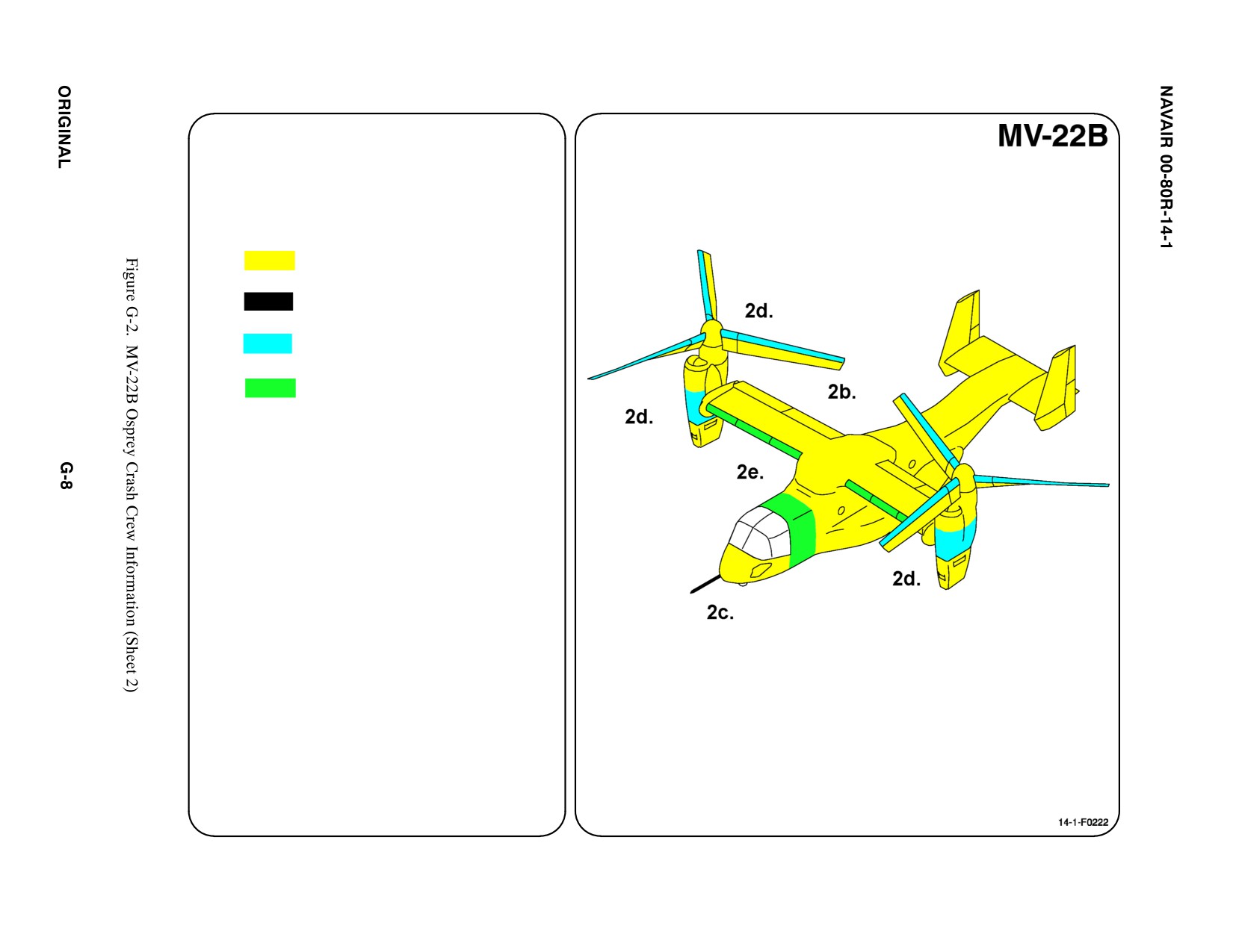
2. AIRFRAME MATERIALS
a. N/A
b. Other
Fiberglass/Carbon Epoxy
Composite/Glass Epoxy
Composite
c. Steel
d. Titanium
e. Aluminum
f. N/A
g. N/A
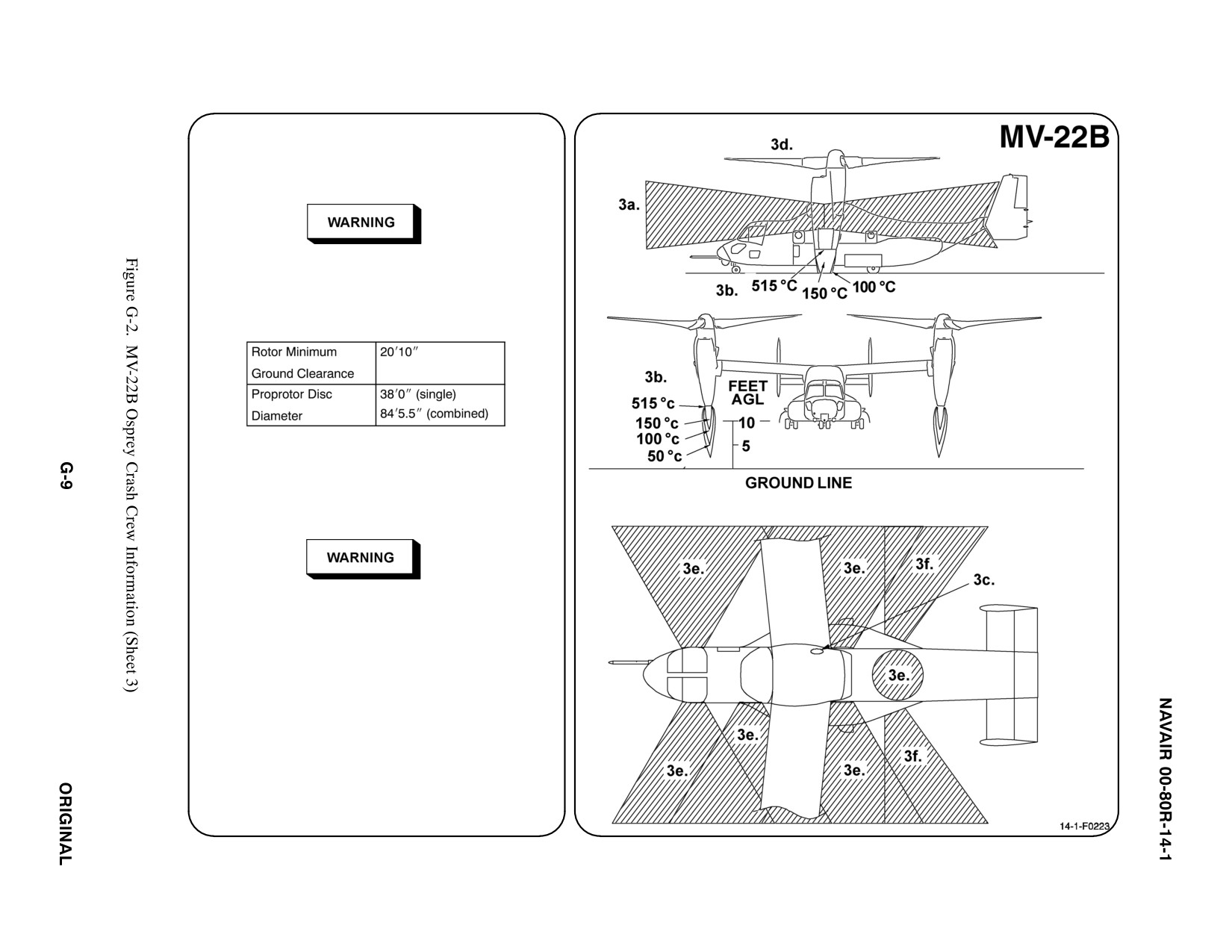
3. AIRCRAFT DANGER AREAS
a. Turbine Blade Failure — 300i
b. Engine Exhaust
After landing, engine exhaust is deflected 45_
away (outboard) from the aircraft.
c. APU Exhaust (Top)
d. Rotors
e. Escape Windows/Hatches — 50i
f. Chaff/Flares
4. AIRCRAFT ENTRY
a. NORMAL ENTRY
D Do not approach aircraft until it has been
shutdown and rotors have come to a
complete stop.
D Solid propellant inert gas generator fire
extinguishing systems discharge an inert gas
mixture that appears as voluminous white
smoke as the mixture is expelled from the
aircraft. 123
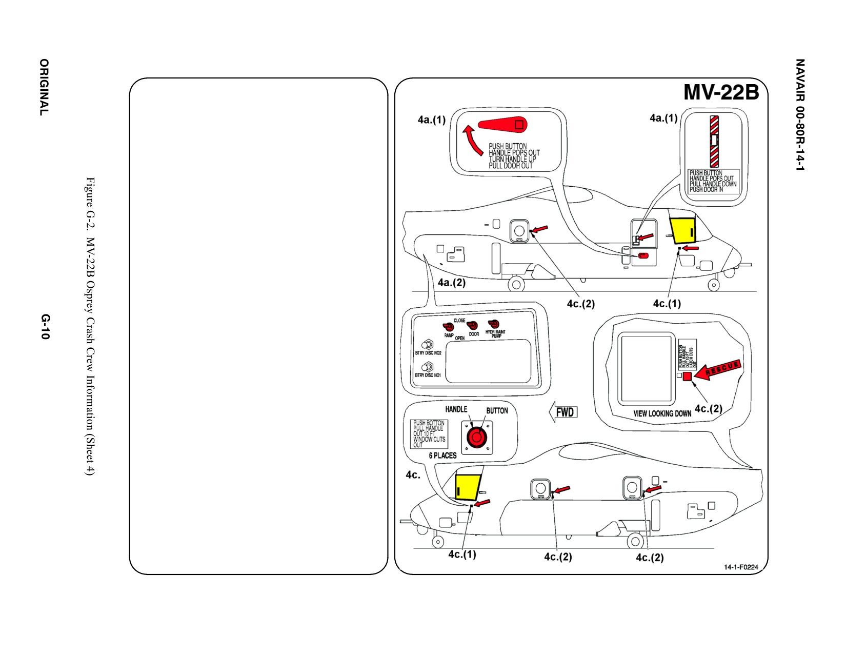
4.
AIRCRAFT ENTRY (CONT.)
a.
NORMAL ENTRY (CONT.)
Normal entry to the flight compartment, and
passenger and/or cargo compartment is
through the forward entrance door on the
starboard side. The door can be opened
from inside or outside the aircraft.
(1) On lower door: Push button in center of
handle, handle will pop out. Turn handle
up and pull, door will hinge downward to
provide entry steps. On upper door: Push
button in center of handle, handle will pop
out. Pull handle down and push door in.
Alternate entry to the flight compartment,
and passenger and/or cargo compartment is
through the cargo ramp/door. The cargo
ramp/door can be opened from inside or
outside the aircraft. The External Ramp
Control Panel is located on the aft corner of
the starboard sponson.
(2) On the External Ramp Control Panel:
Activate the HYD MAINT PUMP switch,
the RAMP directional switch, and the
DOOR directional switch
simultaneously. Release all three
switches when cargo ramp/door reaches
desired position.
b. N/A
c.
EMERGENCY ENTRY
Emergency entry can be made through two
cockpit jettisonable windows and four
jettisonable cabin escape hatches. The
windows and hatches are jettisoned by the
use of a detonation cord system designed to
cut the windows/hatches from the aircraft. 123
4. AIRCRAFT ENTRY (CONT.) ab
c. EMERGENCY ENTRY (CONT.)
D
Flying debris could injure personnel
positioned within 50 feet of the jettisoned
windows/hatches.
D
Activation of the cabin window and cabin
escape hatch jettison system when fuel
and/or vapors are present may result in a
fire.
D
The high sound levels that occur when the
explosive escape system hatches are
jettisoned can damage hearing if hearing
protection is not worn.
D
Cockpit side windows shall be jettisoned
one at a time. Failure to comply may result
in personnel injury or death to aircrew.
(1) Cockpit windows: Push button, handle
will pop out. Grasp handle and, at a
45_ angle, extend to end of lanyard
(approximately 10 feet). Face away
from aircraft and pull handle to initiate
detonation.
(2) Cabin escape hatches: Two on left
side, one on right side, and one in aft
cabin overhead. Push button, handle
will pop out. Grasp handle and, at 45_
angle, extended to end of lanyard
(approximately 10 feet). Face away
from aircraft and pull handle to initiate
detonation.1234
d. N/A
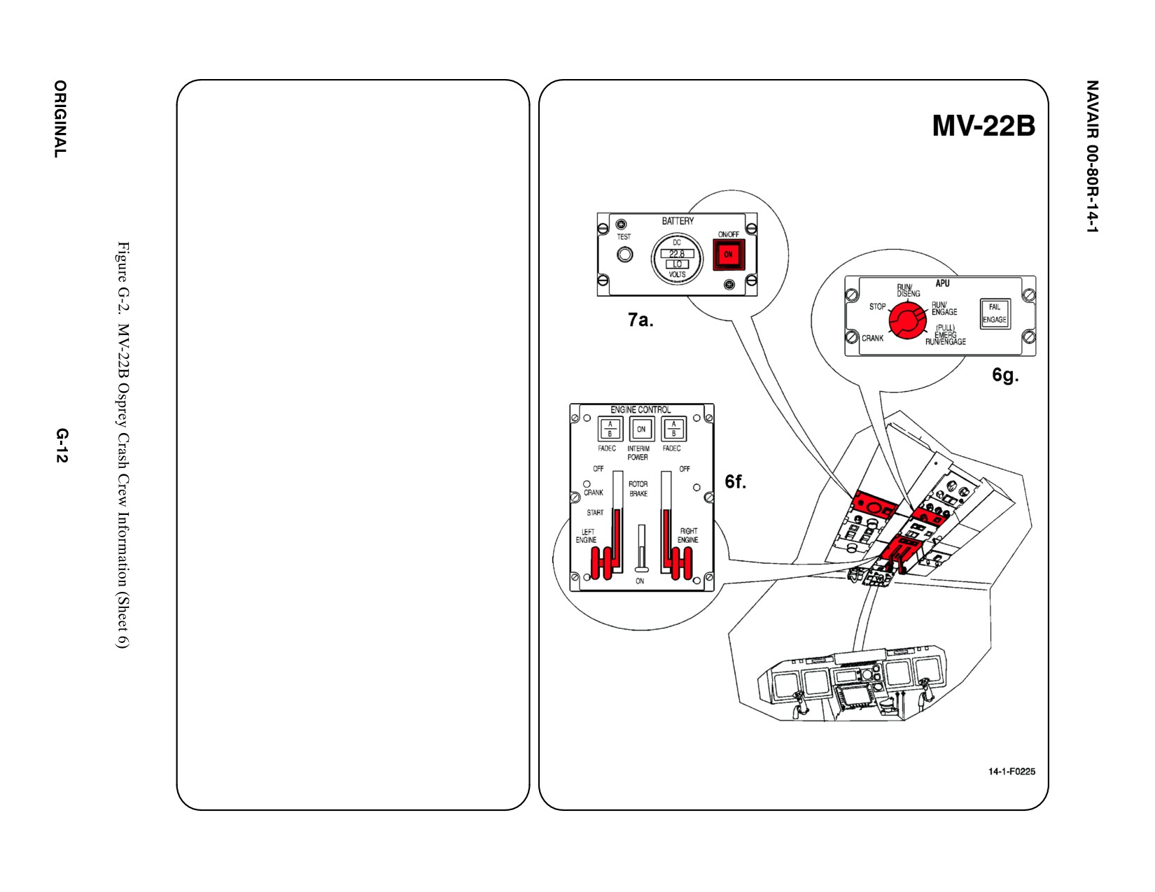
5.
N/A
6.
ENGINE SHUTDOWN
a. N/A
b. N/A
c. N/A
d. N/A
e. N/A
f. Apply INBOARD pressure to Control Levers
and MOVE levers to extreme AFT position
(OFF).
g. APU
Position APU rotary switch to STOP. APU
shutdown will be automatic.
7.
BATTERY
The primary purpose for the battery is for
starting the APU. One 24-volt sealed, lead-acid
battery is located in the cabin overheard and is
accessible from inside the cabin.
a. PUSH battery switch to turn battery ON/OFF.
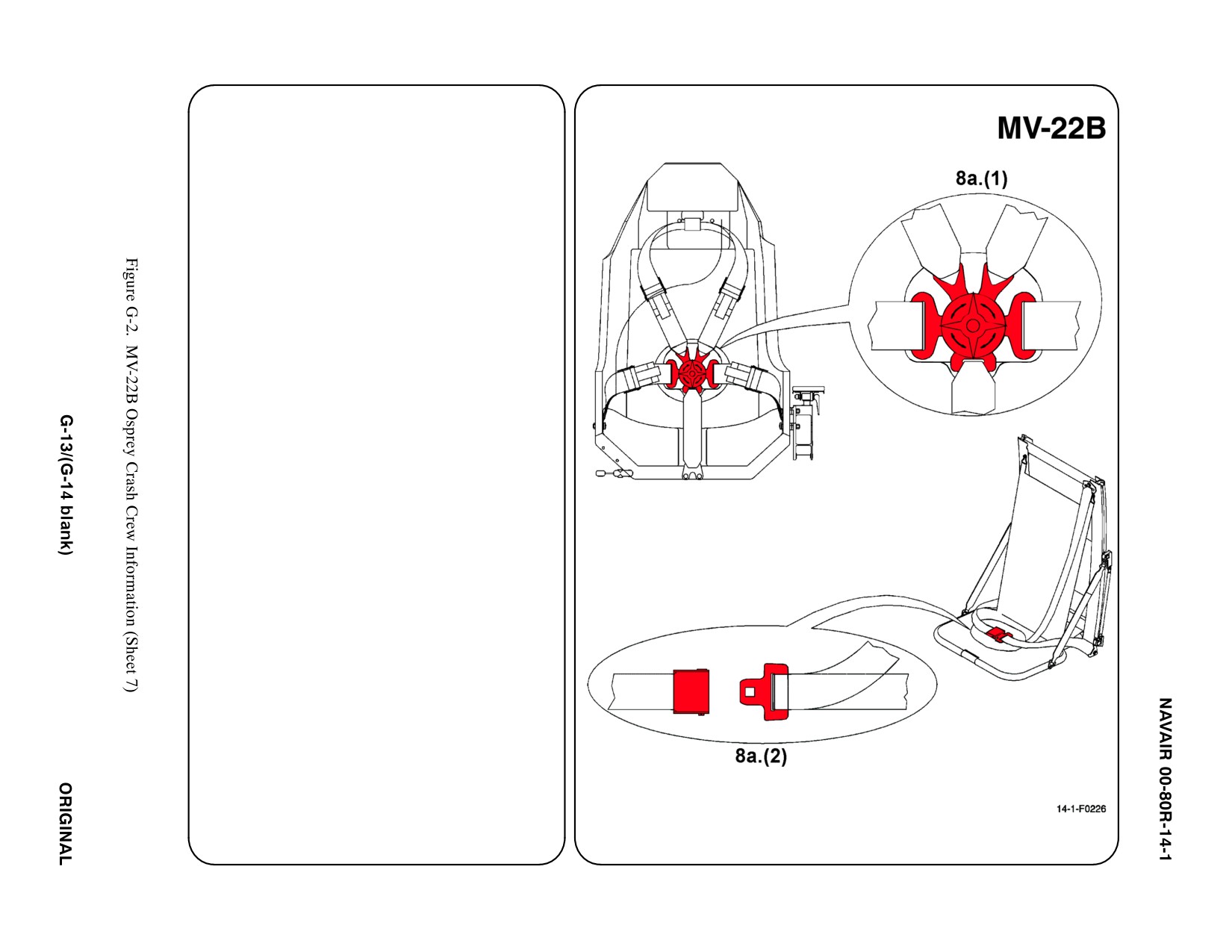
8. CREW RELEASE
The pilot, copilot, and cockpit jump seat restraint
system consists of two lap straps, crotch strap
and attaching rotary buckle, and a shoulder
harness. Passengers and crewmembers have
lap belts and a shoulder harness only.
a. PERSONNEL SERVICE, QUICK
DISCONNECT
(1) PILOT, COPILOT, AND COCKPIT JUMP
SEAT: TURNING rotary buckle knob 1/4
turn will RELEASE lap straps and
shoulder harness from crotch strap.
(2) PASSENGER/CREWMEMBER: LIFT
BUCKLE to RELEASE lap belt and
shoulder harness (airline type).
b. N/A
c. N/A
d. N/A


NAVAIR 00-80R-14-1
APPENDIX H
References
H.1
RESCUE AND FIREFIGHTING PUBLICATIONS
The following publications contain additional information about Aircraft Rescue and Firefighting Procedures.
AIRCRAFT TYPE
PUBLICATION TITLE
PUBLICATION NUMBER
USN/USMC AIRCRAFT
NATOPS U.S. NAVY
NAVAIR 00-80T-14
AIRCRAFT FIREFIGHTING
AND RESCUE
USAF AIRCRAFT
TECHNICAL MANUAL
USAF T.O. 00-105E9
AIRCRAFT EMERGENCY
RESCUE INFORMATION
H.2
AIRCRAFT SYSTEMS PUBLICATION
The following publications contain additional information about USN and USMC aircraft equipment and escape
procedures.
AIRCRAFT TYPE
PUBLICATION TITLE
PUBLICATION NUMBER
AV-8B/TAV-8B Harrier
AV-8B/TAV-8B NATOPS Flight Manual
NAVAIR A1-AV8BB-NFM-000
F-5E/F/N Tiger II
F-5E/F/N NATOPS Flight Manual
NAVAIR 01-F5AAA-1
F-16N Fighting Falcon
F-16A/B Flight Manual
USAF T.O. 1F-16A-1
F/A-18A/B/C/D Hornet
F/A-18A/B/C/D NATOPS Flight Manual
NAVAIR A1-F18AC-NFM-000
F/A-18A/B/C/D Line Maintenance Emergency
NAVAIR A1-F18AC-LMM-020
Procedures
F/A-18E/F Super Hornet
F/A-18E/F NATOPS Flight Manual
NAVAIR A1-F18EA-NFM-000
F/A-18E/F Line Maintenance Emergency Procedures
NAVAIR A1-F18EA-LMM-020
EA-6B Prowler
EA-6B BLK 89A/89, 82 NATOPS Flight Manual
NAVAIR 01-85ADC-1
EA-6B ICAP II BLK 3 Preliminary
NAVAIR 01-85ADX-1
ąNATOPS Flight Manual
EA-6B ICAP III BLK II Preliminary
NAVAIR 01-85ADZ-1
ąNATOPS Flight Manual
EA-18G Growler
EA-18A Preliminary NATOPS Flight Manual
NAVAIR 01-E18GA-NFM-000
E-2C Hawkeye
E-2C NATOPS Flight Manual
NAVAIR 01-E2AAF-1
E-6B Mercury
E-6B NATOPS Flight Manual
NAVAIR A1-E6AAB-NFM-000
EP-3E
EP-3E NATOPS Flight Manual
NAVAIR 01-75EPS-1
P-3C AIP Orion
P-3C NATOPS Flight Manual
NAVAIR 01-75PAC-1
P-3A/B/C
P-3A/B/C NATOPS Flight Manual
NAVAIR 01-75PAG-1
S-3B Viking
S-3B NATOPS Flight Manual
NAVAIR 01-S3AAB-1
C-2A Greyhound
C-2A NATOPS Flight Manual
NAVAIR A1-C2AHA-NFM-000
C-9B/DC-9B Skytrain II
C-9B NATOPS Flight Manual
NAVAIR 01-C9BAAA-1
UC-12B/F/M Super King Air
UC-12B/F/M NATOPS Flight Manual
NAVAIR A1-C12BM-NFM-000
H-1
ORIGINAL

NAVAIR 00-80R-14-1
AIRCRAFT TYPE
PUBLICATION TITLE
PUBLICATION NUMBER
C-20A/D/G Gulfstream III/III/IV
C-20A Flight Manual
USAF T.O. 1C-20A-1
C-20D NATOPS Flight Manual
NAVAIR 01-C20DAAA-1
C-20G NATOPS Flight Manual
NAVAIR 01-C20GAAA-1
C-26D Metroliner
C-26D NATOPS Flight Manual
NAVAIR 01-C26DA-NFM-000
UC-35C/D Citation
UC-35C/D NATOPS Flight Manual
NAVAIR 01-C35CAA-1
C-37A/B Gulfstream V/550
C-37A NATOPS Flight Manual
NAVAIR 01-C37A-1
C-37B NATOPS Flight Manual
NAVAIR 01-C37B-1
C-40A Clipper
C-40A NATOPS Flight Manual
NAVAIR 01-C40AA-NFM-000
C-130T &
C-130T NATOPS Flight Manual
NAVAIR 01-75GAL-1
KC-130F/R/T/J Hercules
KC-130F NATOPS Flight Manual
NAVAIR
01-75GAA-1
KC-130J NATOPS Flight Manual
NAVAIR
01-75GAJ-1
KC-130R NATOPS Flight Manual
NAVAIR
01-75GAG-1
KC-130T & KC-130T-30 NATOPS Flight Manual
NAVAIR
01-75GAH-1
T-2C Buckeye
T-2C NATOPS Flight Manual
NAVAIR
01-60GAB-1
T-6A Texan II
T-6A NATOPS Flight Manual
NAVAIR A1-T6AAA-NFM-100
TC-12B Super King Air
TC-12B NATOPS Flight Manual
NAVAIR
01-C12AAB-1
T-34C Turbo Mentor
T-34C NATOPS Flight Manual
NAVAIR
01-T34AAC-1
T-39D/G/N Sabreliner
T-39D NATOPS Flight Manual
NAVAIR
01-60GBA-1
T-39G/N NATOPS Flight Manual
NAVAIR
01-60GBE-1
T-44A/C King Air
T-44A NATOPS Flight Manual
NAVAIR
01-T44AAA-1
T-44C NATOPS Flight Manual
NAVAIR
01-T44AAC-1
T-45A/C Goshawk
T-45A NATOPS Flight Manual
NAVAIR A1-T45AB-NFM-000
T-45C NATOPS Flight Manual
NAVAIR A1-T45AC-NFM-000
MV-22B Osprey
MV-22B NATOPS Flight Manual
NAVAIR A1-V22AB-NFM-000
AH-1W/Z Super Cobra
AH-1W NATOPS Flight Manual
NAVAIR
01-H1AAC-1
AH-1Z NATOPS Flight Manual
NAVAIR
01-H1AAD-1
UH-1N/Y Iroquois
UH/HH-1N NATOPS Flight Manual
NAVAIR
01-110HCE-1
UH-1Y NATOPS Flight Manual
NAVAIR
01-110HCG-1
UH-3H & UH-3E(ET) Sea King
UH-3H & UH-3H(ET) NATOPS Flight Manual
NAVAIR
01-230HLH-1
CH-46E Sea Knight
CH-46E NATOPS Flight Manual
NAVAIR A1-H46AE-NFM-000
CH-53D Sea Stallion
CH-53D NATOPS Flight Manual
NAVAIR
01-230HMA-1
CH-53E Super Stallion
CH-53E NATOPS Flight Manual
NAVAIR A1-H53BE-NFM-000
MH-53E Sea Dragon
MH-53E NATOPS Flight Manual
NAVAIR A1-H53ME-NFM-000
TH-57B/C Sea Ranger
TH-57B/C NATOPS Flight Manual
NAVAIR
01-H57BC-1
SH-60B Seahawk
SH-60B NATOPS Flight Manual
NAVAIR A1-H60BB-NFM-000
SH-60F & HH-60H Seahawk
H-60F/H NATOPS Flight Manual
NAVAIR A1-H60CA-NFM-000
MH-60R Seahawk
MH-60R NATOPS Flight Manual
NAVAIR A1-H60RA-NFM-000
MH-60S Knighthawk
MH-60S NATOPS Flight Manual
NAVAIR A1-H60SA-NFM-000
ORIGINAL
H-2

NAVAIR 00-80R-14-1
APPENDIX I
NATOPS Question and Answer Bank
Test question and answer bank under development.
I-1/(I-2 blank)
ORIGINAL


NAVAIR 00-80R-14-1
INDEX
Page
Page
No.
No.
A
C
Canopies
3-2
Aircraft:
CCID summaries and other information
2-4
Approaching crashed
3-1
CCID warnings summary
3-20
Systems publication
H-1
Aircraft warnings
3-21
Warnings
3-21
Codes:
Aircraft CCIDs
2-2
Aircraft CCID color
2-2
Color codes
2-2
Ejection seat CCID color
2-4
Command, NATOPS cognizant
1-4
Essential information categories
2-2
Complementary publications
1-2
Aircraft danger areas
3-1
Composite material
3-2
Armament
3-1
Connections, personal services
3-16
Composite material
3-2
Contents
1-1
Engines running
3-1
Crew extraction
4-2
Fire
3-2
Crewmember:
Rescue crewmember duty assignments
1-1
Radiation
3-1
Rescue crewmember selection criteria
1-1
Tires
3-1
Currency of CCID information
2-5
Aircrew rescue sequence
3-7
Ejection seat safety information
3-7
D
Engine shutdown
3-9
Doors
3-2
Personnel restraints
3-15
Duty assignments, rescue crewmember
1-1
Removal of face/oxygen mask
3-9
Approaching crashed aircraft
3-1
E
Areas:
Ejection seat:
Aircraft danger
3-1
Safety information
3-7
Forcible entry into fuselage
3-4
Systems
4-1
Warnings
3-8
Armament
3-1
Ejection seat CCIDs
2-2
Assembly:
Color codes
2-4
MV-22B left/right center, left forward
Essential information categories
2-4
cabin fuselage hatch severance
Electronic radiation hazards
3-20
assembly source data
G-2
Emergency:
MV-22B overhead cabin fuselage
Entry
3-4
hatch severance assembly source data
G-2
Harness release
3-16
MV-22B side canopy
Engine shutdown
3-9
severance assembly source data
G-4
Engines running
3-1
Assignments, rescue crewmember duty
1-1
Entry and exit points
3-2
Automatic sea water actuated release system (SEA-
Canopies
3-2
WARS) release fitting
3-19
Doors
3-2
Index-1
ORIGINAL

NAVAIR 00-80R-14-1
Page
Page
No.
No.
Emergency entry
3-4
M
Forcible entry
3-4
Miscellaneous hazards
3-20
Hatches
3-2
MV-22B external initiator source data
G-3
Normal canopy opening
3-3
Description
G-3
Equipment:
Function
G-3
Seat restraint
3-15
Operation
G-3
Special mission aircrew equipment
MV-22B internal initiator source data
G-4
MCK-0 through MCK-5 series mask
Description
G-4
aircrewman, CBR protective respirator
Function
G-4
and tactical ventilator
3-9
Operation
G-4
MV-22B left/right center, left forward
F
cabin fuselage hatch severance
assembly source data
G-2
Fire
3-2
Description
G-2
Hazards
3-19
Function and location
G-2
Forcible entry
3-4
Operation
G-2
into Fuselage areas
3-4
MV-22B overhead cabin fuselage hatch
Transparent acrylic plastic
3-4
severance assembly source data
G-2
Description
G-3
H
Function and location
G-2
Operation
G-3
Hatch(es)
3-2
MV-22B side canopy severance
MV-22B left/right center, left forward
assembly source data
G-4
cabin fuselage hatch severance
Description
G-4
assembly source data
G-2
Function and location
G-4
MV-22B overhead cabin fuselage
Operation
G-4
hatch severance assembly source data
G-2
MV-22B thruster source data
G-5
Hazards:
Description
G-5
Electronic radiation
3-20
Function
G-5
Fire
3-19
Operation
G-5
Miscellaneous
3-20
MV-22B TLX line source data
G-5
Toxic
3-20
Description
G-5
Function
G-5
I
Operation
G-5
Integrated torso harness
3-16
N
NATOPS:
L
Advisory group
1-3
Lap belt
3-15
Cognizant command
1-4
and Shoulder harness combination
3-15
Model manager
1-4
Leg retention devices
3-16
Normal canopy opening
3-3
ORIGINAL
Index-2

NAVAIR 00-80R-14-1
Page
Page
No.
No.
O
Fire hazards
3-19
Miscellaneous hazards
3-20
Other related publications
1-2
Toxic hazards
3-20
Complementary publications
1-2
Seat:
Other crash and salvage-related
Ejection seat CCID color codes
2-4
publications
1-3
Ejection seat CCID
Other NATOPS publications
1-2
essential information categories
2-4
Ejection seat CCIDs
2-2
P
Ejection seat safety information
3-7
Personal services connections
3-16
Ejection seat systems
4-1
Personnel restraints
3-15
Ejection seat warnings
3-8
Automatic sea water actuated release
Restraint equipment
3-15
system (SEAWARS) release fitting
3-19
Safetying/safing
4-2
Emergency harness release
3-16
Selection criteria, rescue crewmember
1-1
Leg retention devices
3-16
Special mission aircrew equipment
Personal services connections
3-16
MCK-0 through MCK-5 series mask
Seat restraint equipment
3-15
aircrewman, CBR protective respirator
Torso harness suit and torso harness
3-16
and tactical ventilator
3-9
Universal water activated release
System(s):
system (UWARS)
3-19
Aircraft systems publication
H-1
Program manager
1-4
Automatic sea water actuated release
system (SEAWARS) release fitting
3-19
R
Ejection seat
4-1
Universal water activated release
Radiation
3-1
system (UWARS)
3-19
Removal of face/oxygen mask
3-9
Special mission aircrew equipment
MCK-0 through MCK-5 series mask
T
aircrewman, CBR protective respirator
and tactical ventilator
3-9
Tires
3-1
Rescue and firefighting publications
H-1
Torso harness suit and torso harness
3-16
Rescue crewmember:
Toxic hazards
3-20
Duty assignments
1-1
Training
1-2, 4-1
Selection criteria
1-1
Procedures
4-1
Responsibilities
1-3
Transparent acrylic plastic
3-4
NATOPS advisory group
1-3
NATOPS cognizant command
1-4
U
NATOPS model manager
1-4
Program manager
1-4
Universal water activated release
system (UWARS)
3-19
S
Safety
3-19
W
CCID warnings summary
3-20
Electronic radiation hazards
3-20
Waivers
1-4
Index-3/(4 blank)
ORIGINAL
