NAVAIR 00-80R-14-1 NATOPS U.S. NAVY AIRCRAFT EMERGENCY RESCUE INFORMATION MANUAL (2009) - page 2
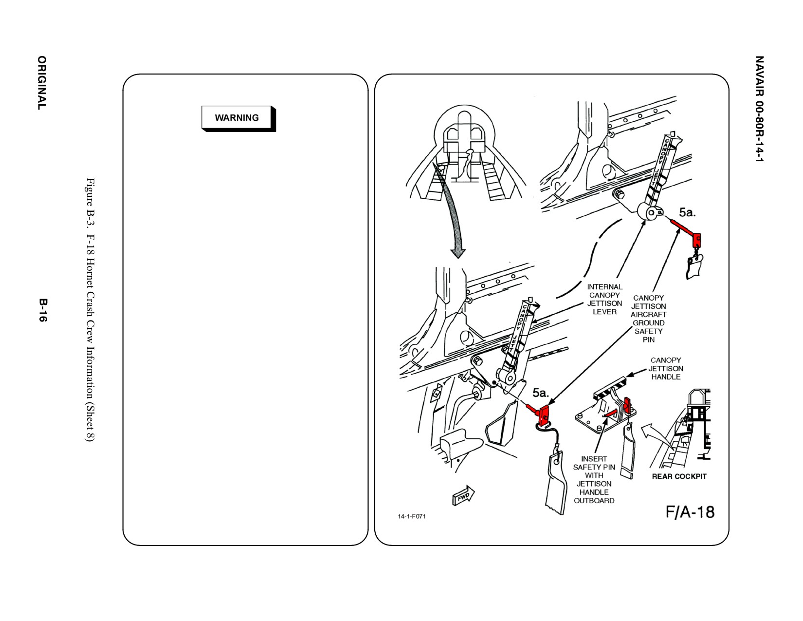
5. CANOPY SAFETY
D During flight of the F-18 aircraft, a high
voltage (100,000 volts) static electrical
charge may build up and be stored in the
windshield and canopy. After flight, static
charge buildup must be discharged using
anti-static
gloves
(part
number
SG-200-93-y-F150), before personnel
can safely touch the windshield and
canopy.
D Canopy has dual rocket motors mounted
on canopy frame. With canopy open,
rescue personnel may be seriously injured
if rocket motors are ignited.
a. CANOPY UNLATCH THRUSTER
To safety Canopy Unlatch Thruster and
Canopy Rocket Motors, INSERT safety
pin, if available, into Canopy Jettison
Handle.
Note
Insert safety pin with jettison lever forward.
On F/A-18B/D/F/G (two seat), insert the canopy
jettison safety pin in the Rear Internal Canopy
Jettison Lever.
1234
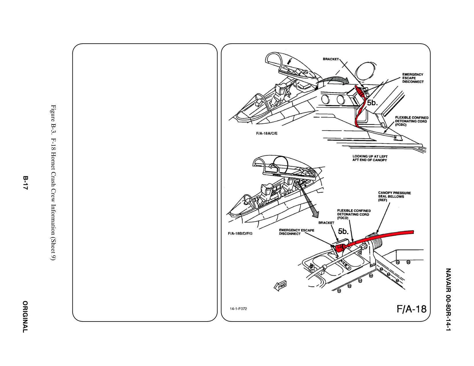
5. CANOPY SAFETY (CONT.) a
b. CANOPY/AIRCRAFT QUICK
DISCONNECT
GRASP quick disconnect hose and PULL
DOWN to disarm Canopy Thruster and
Rocket Motors.
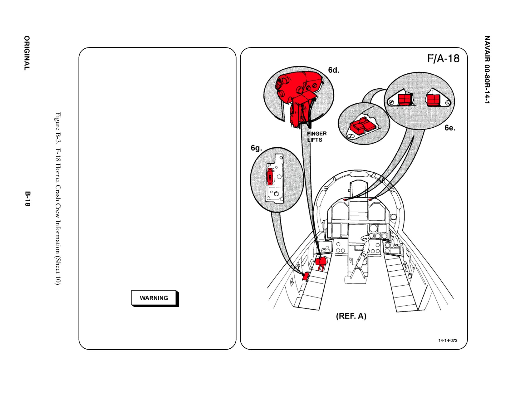
6.
ENGINE/APU SHUTDOWN
(NORMAL/EMERGENCY)
(INTERNAL VIEW) (REF A)
The engines may be shut down by using
the throttles or fuel shutoff valve controls.
a. N/A
b. N/A
c. N/A
d. THROTTLES
RAISE finger lifts and MOVE throttles fully
AFT to OFF position.
e. FUEL SHUTOFF VALVE CONTROLS
Lift guard and PRESS the Left and Right
FIRE warning lights. A time delay of
approximately 30 seconds or less (with
engines at MIL through IDLE) may be
expected before engine shutdown occurs.
Note
On aircraft 160775 thru 160781 and F/A-18B
aircraft BUNO 160782, valve levers are located
AFT of throttles. PULL levers to FULL UP
position.
f. N/A
g. APU
Auxiliary Power Unit may be shut down by
placing APU Switch in OFF position.
Puddling of fuel under aircraft indicates
presence of residual fuel in engine bay. With
APU running, this can cause fire/explosion.
Ensure APU shutdown prior to crewmember
rescue.
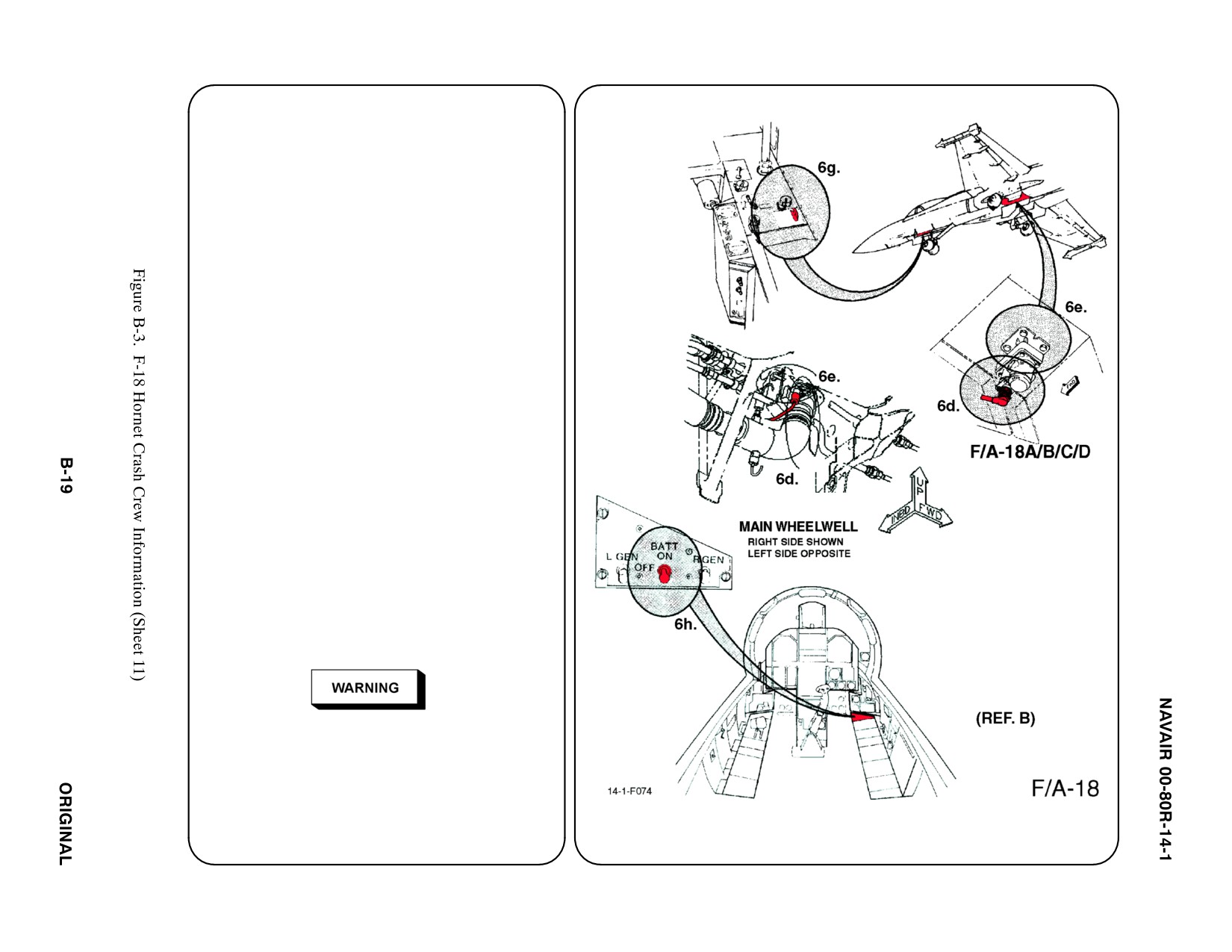
6a. ENGINE/APU SHUTDOWN
ą (NORMAL/EMERGENCY)
ą (EXTERNAL VIEW) (REF B)123456
The engines may be shut down by using the
throttles or fuel shutoff valve controls.
a. N/A
b. N/A
c. N/A
d. THROTTLES
RAISE finger lifts and MOVE throttles
fully AFT to OFF position.
e. FUEL SHUTOFF VALVE CONTROLS
Lift guard and PRESS the Left and
Right FIRE warning lights. A time delay
of approximately 30 seconds or less
(with engines at MIL through IDLE)
may be expected before engine
shutdown occurs.
Note
On aircraft 160775 thru 160782 (F/A-18A,
Cum 1 thru 7; F/A-18B, Cum 1), valve levers
are located AFT of throttles. PULL levers to
FULL UP position.
f. N/A
g. APU
Auxiliary power unit may be shut down
by placing APU switch in OFF position.
If APU is inoperative,a huffer and electric
power are required for engine(s)shutdown
in case of tailpipe fire.
h. BATTERY switch
Place switch in OFF position.
7. N/A
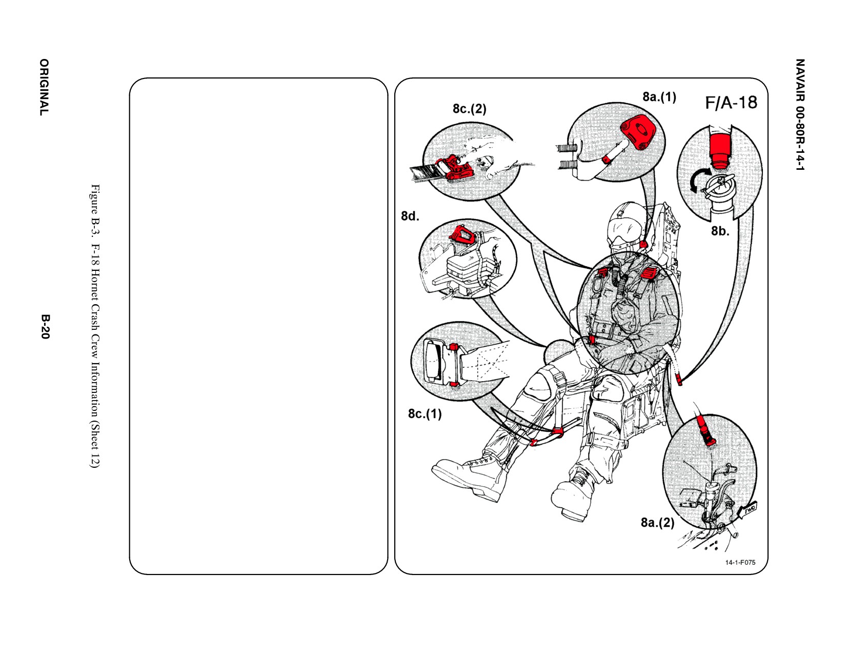
8.
CREW RELEASE
The crewmember is attached to the seat by
the use of an integrated harness and leg
restraints. Additionally, the oxygen/
communication lead is attached to the
survival kit. If the crewmember is wearing an
anti-G suit, a hose will be attached to an
outlet on the LH console.
a.
PERSONNEL SERVICE/QUICK
DISCONNECT
(1) Remove oxygen mask by PULLING
DOWN on release tabs on either side
of mask.
(2) Disconnect oxygen/communication
lead at the survival kit. GRASP
knurled fitting on hose and PULL UP
to disconnect.
(3) Release hip quick disconnect con-
nector (QDC).
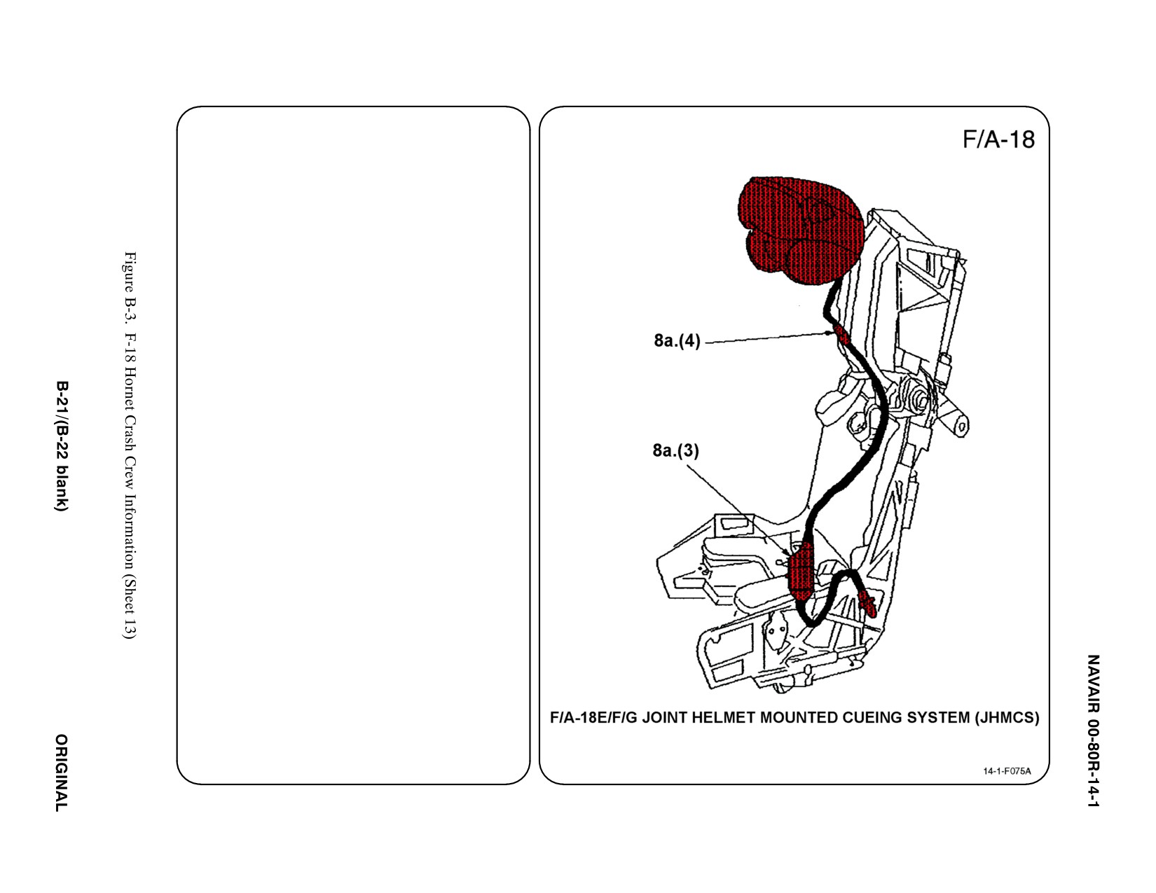
(4) Release helmet release connector for
the Joint Helmet Mounted Cueing
System (JHMCS).
b. RESTRAINT SUIT BELTS/RELEASE
PULL anti-G suit hose from LH console.
c.
HARNESS STRAPS/LEG RESTRAINT
RELEASE
(1) Release leg garters by APPLYING
PRESSURE to both sides of each
quick disconnect fitting.
(2) Release two lap belt, then two
shoulder harness koch fittings.
8. CREW RELEASE (CONT.)
d. EMERGENCY RELEASE
PRESS thumb button on FWD part of
Manual Override Handle (right Side of
seat) and ROTATE handle AFT. This
positions the Safe/Armed Handle UP in
safe position and releases lower leg
restraint lines. However, parachute and
survival kit will remain attached to
crewmember.

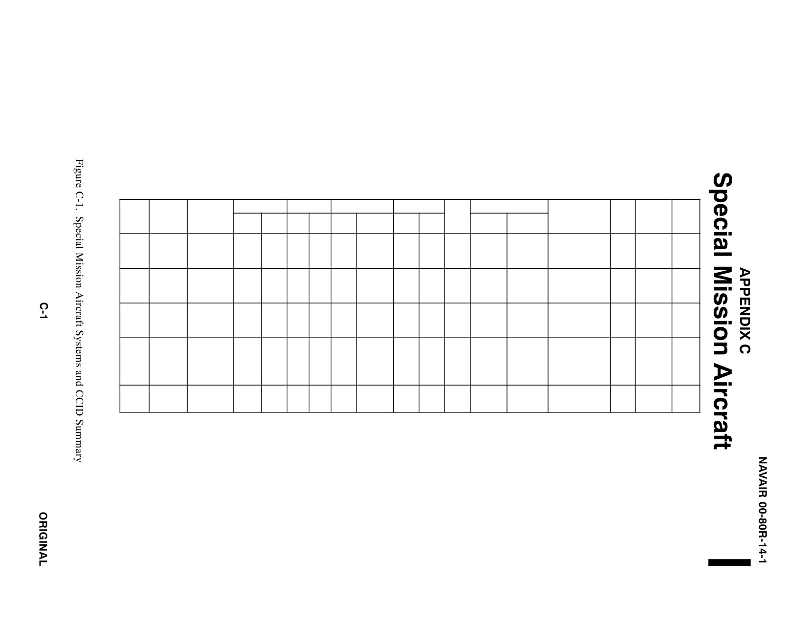
SPECIAL MISSIONS AIRCRAFT SYSTEMS
AND
CRASH CREW INFORMATION DIAGRAMS SUMMARY
FUEL (GAL)
OIL (GAL)
OXYGEN
PNEU SYS
ORDNANCE
AIRFRAME
FWD
EJECT
TYPE
NAME
MATERIALS
INT
EXT
ENG
HYD
LOX
BOTTLE
GAS
AIR
GUN
FIRE
FREE FALL
PYROTECHNICS
BTRY
SYS
S.O.B.
PORT (1)
ALUMINUM
BAIL OUT
N2
E-2C
HAWKEYE
STEEL
1824
NONE
16
20
10L
3000
NONE
NONE
NONE
NONE
FLARES
1
NONE
5
BOTTLES
FIBERGLASS
(5)
PSI
PYLON EJECTOR
ALUMINUM
SEAT
MARTIN-B
(3)
N2
CARTRIDGES (5)
EA-6B
PROWLER
STEEL
2300
1500
3.9
18.6
PAN
3000
NONE
NONE
MISSILES
NONE
1
AKER MK
4
10L
STA.
FIBERGLASS
(4)
PSI
CHAFF/FLARES
GRUEA-7
PYLON EJECTOR
ALUMINUM
BOMBS
AB-18
(3) FIXED
N2
MISSILES
CARTRIDGES (18)
P-3
ORION
STEEL
9200
NONE
40
46
NONE
3000
NONE
NONE
MINES
1
NONE
C-23
(7) PORT
ROCKETS
STA.
FIBERGLASS
PSI
SONOBUOY
CHAFF/FLARES
E-27
PYLON EJECTOR
ALUMINUM
CARTRIDGES (6)
STEEL
SEAT
MISSILES
BOMBS
STA.
ESCAPAC
S-3
VIKING
1933
530
4.8
7.2
10L
PAN
NONE
NONE
NONE
MINES
0
4
FIBERGLASS
ROCKETS
CHAFF/FLARES
1E-1
(4)
SONOBUOY
MAGNESIUM
CANOPIES
EJECTION SEATS
ALUMINUM
N2
E-6
MERCURY
STEEL
24.000
NONE
60.5
72
75L
18
1200
NONE
NONE
NONE
NONE
SIGNAL FLARES
4
NONE
24
FIBERGLASS
PSI
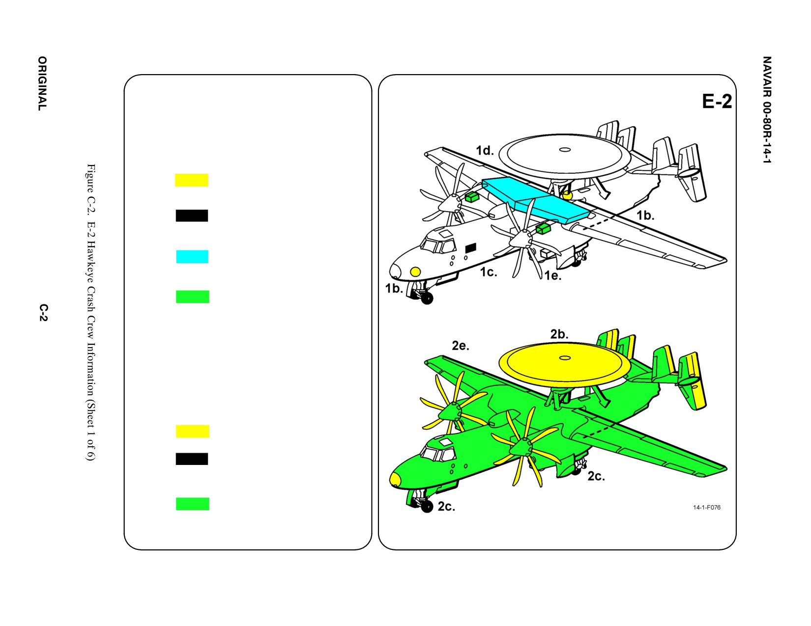
SPECIAL TOOLS/EQUIPMENT
Power Rescue Saw
Crash Axe
1. GENERAL AIRCRAFT INFORMATION
a. N/A
b. Oxygen/LOX
10 L
Portable Cylinder (1)
Bailout Bottle (5)
c. Battery
1
d. Fuel Internal
1824 gal
e. Oil
Engines — 16gaI
Hydraulic — 20 gal
Transmission — 13 gal
f. Pneumatic
System
3000 PSI
2. AIRFRAME MATERIALS
a. N/A
b. Other:
Fiberglass
c. Steel
d. N/A
e. Aluminum
f. N/A
g. N/A
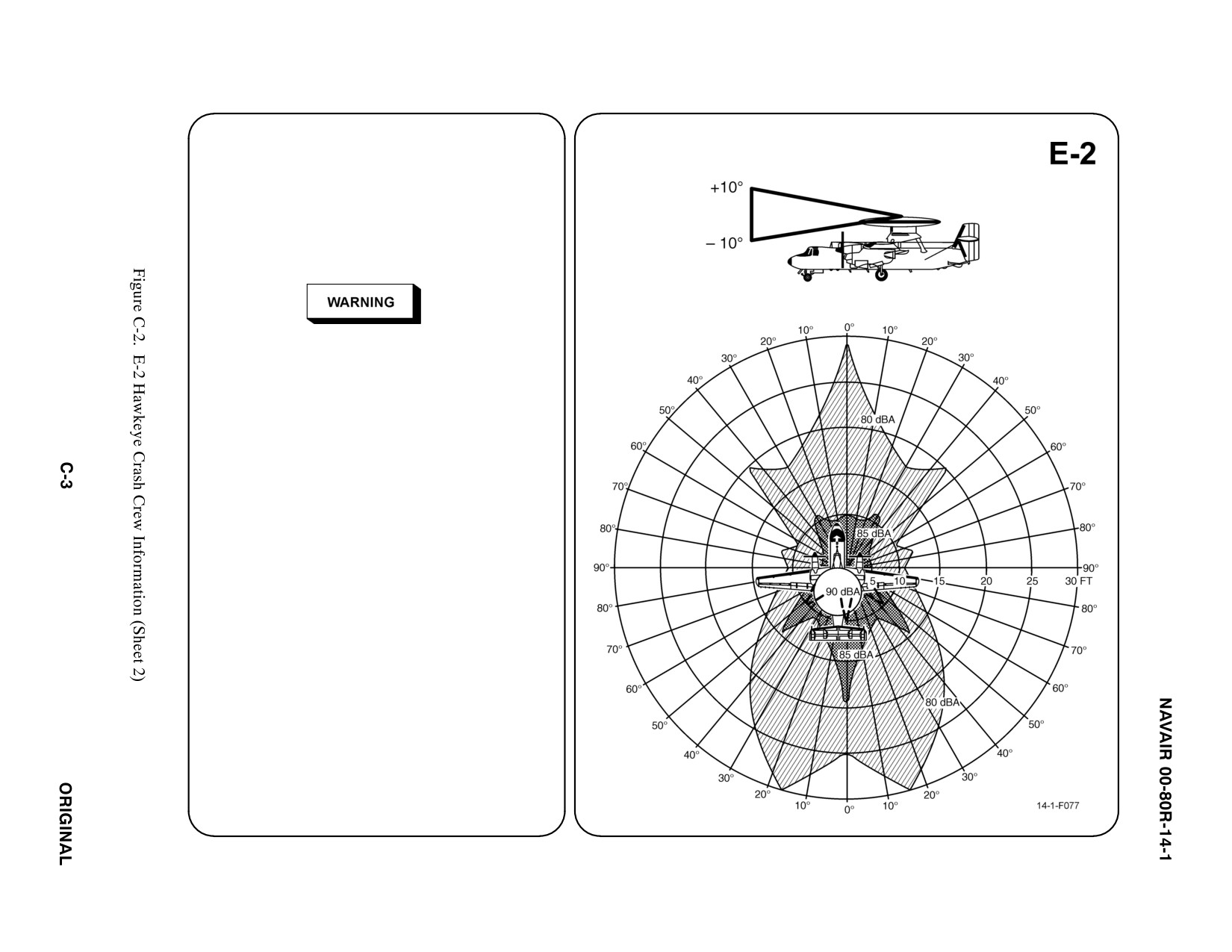
3. AIRCRAFT DANGER AREAS
a. Propeller Danger Zone — 15i
b. Engine Exhaust/Propeller Blast — 28i
c. Radiation
Sector A Main Lobe — 500i
Sector B Side Lobe — 50i
D Radiation may cause steel wool to be set afire
or metallic chips to produce sparks, which in
turn may ignite spilled oils or fuels around
aircraft and buildings.
D Unauthorized transmission aboard ship is
prohibited.
D While there is no apparent danger to person-
nel because of the HF electromagnetic field
generated by the AN/ARQ-34 transmitter,
electrical shock hazards exist if personnel
come into contact with the antenna or the
airframe. All personnel should be cautioned
not to touch the antenna or the airframe while
the AN/ARQ-34 is transmitting.
Note
If antenna is rotated, Sector A must move
accordingly.
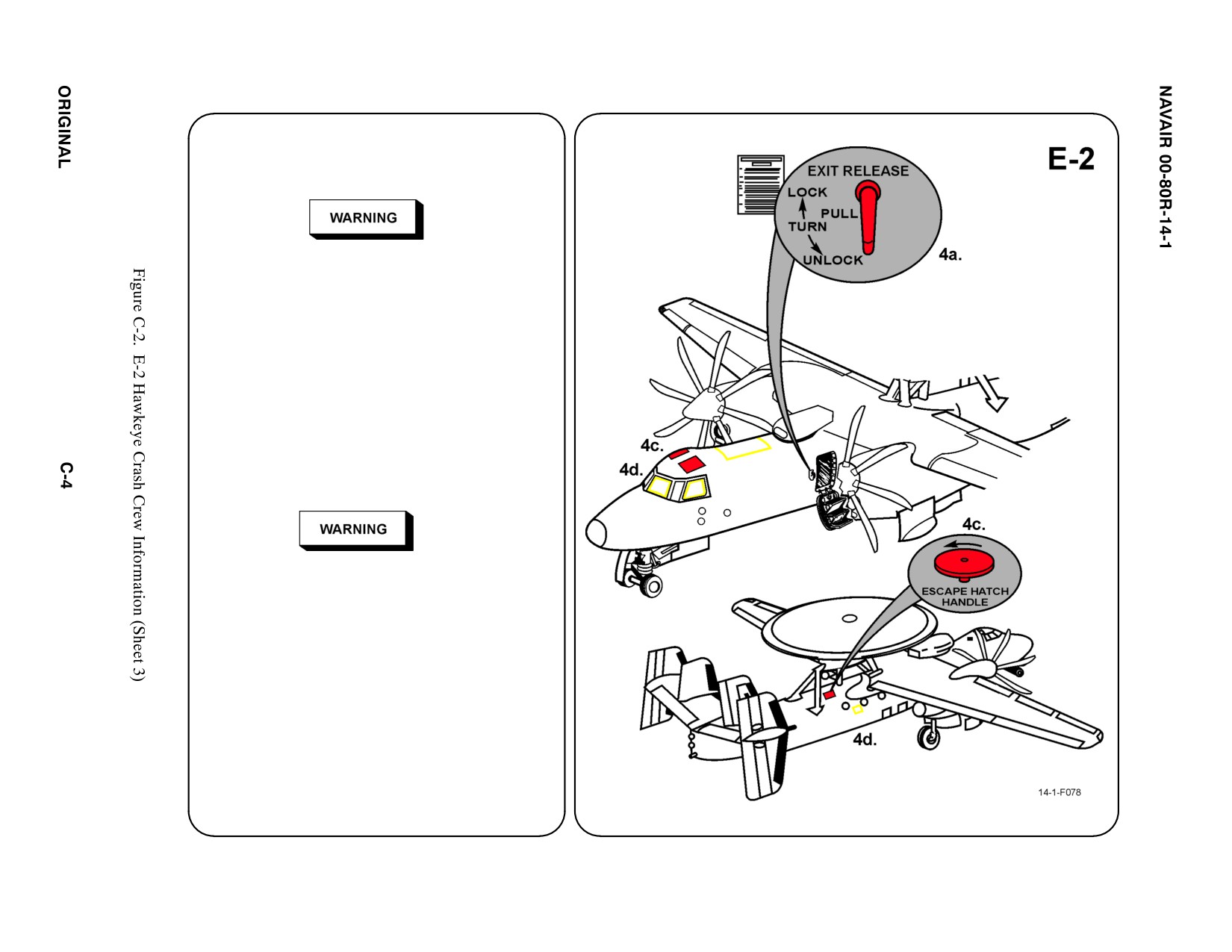
4. AIRCRAFT ENTRY
a. NORMAL ENTRY
(1) Stand FWD of door.
Clearance between door, propeller and forward
edge of door is minimal and extremely dangerous.
If the cabin is pressurized, even slightly, the door
will fly open rapidly. To avoid personal injury,
ensure that there is no residual pressurization
prior to opening the main entrance door.
(2) TURN handle to UNLOCK position.
(3) PULL hand grip on door. SUPPORT
door during opening.
(4) STEP on door when open to secure.
b. N/A
c. EMERGENCY ENTRY
When opened, the CIC compartment ditching
hatch drops into the aircraft; therefore, caution
should be exercised to prevent injury to
crewmember seated below hatch.
Emergency entry is through pilot and copi-
lot escape hatches and the CIC compart-
ment ditching hatch AFT top RH side of
aircraft.
d. FORCED ENTRY
Using power rescue saw or crash axe,
CUT through fuselage FWD on top center
of fuselage and around cockpit windows
and AFT RH side of fuselage.
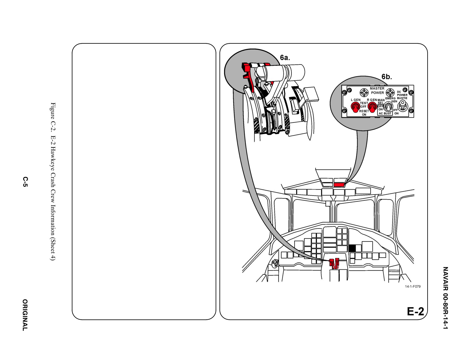
5.
N/A
6.
ENGINE SHUTDOWN
a. CONDITION LEVERS
To move the levers to different positions, the
Detent Release at the outboard side of each
lever must be LIFTED, then MOVE levers to
extreme AFT position.
b. GENERATOR SWITCHES
PLACE Left and Right Generator Switches
in OFF position.
c. N/A
d. N/A
e. N/A
f. N/A
g. N/A
7.
BATTERY
The battery is for the JTIDS only and is located
on the port side of the forward equipment com-
partment adjacent to the cockpit steps. To de-
activate the battery remove the quick discon-
nect fittings.
a. N/A
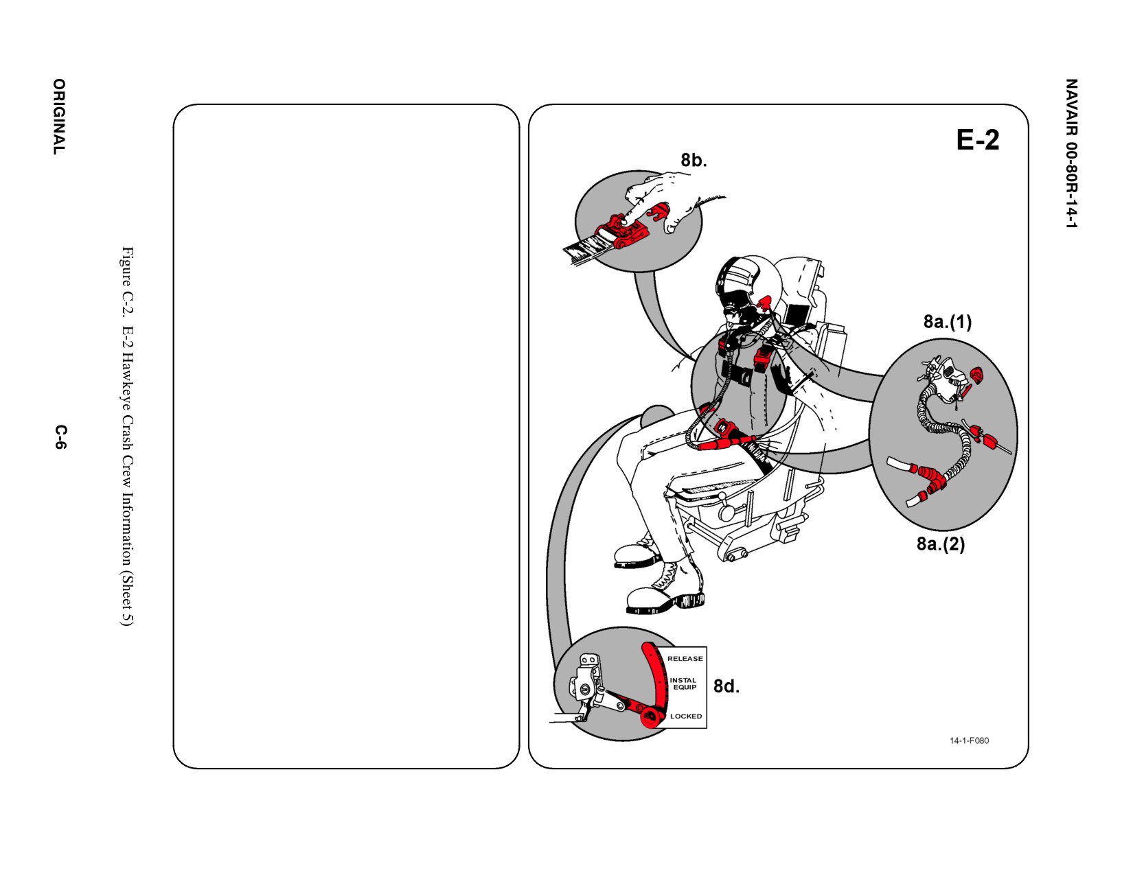
8.
CREW RELEASE (A/P22P-11 CREW
PARACHUTE BACKPACK ASSEMBLY)
Crewmembers are attached to the seats by the
use of a torso harness.
a. PERSONNEL SERVICE, QUICK
DISCONNECT
(1) Remove oxygen mask by PULLING
DOWN on release tabs on either side of
mask.
(2) The oxygen and communications leads
are quick disconnect. To release, PULL
APART at the quick disconnect fittings.
b. RESTRAINT SUIT BELTS/RELEASE
Release two lap belt mini-Koch fittings, then
two shoulder harness koch fittings.
c. N/A
d. EMERGENCY RELEASE
Actuating the Emergency Release Handle
will free the crewmember from the seat.
However, the parachute and survival kit will
remain attached to the crewmember.
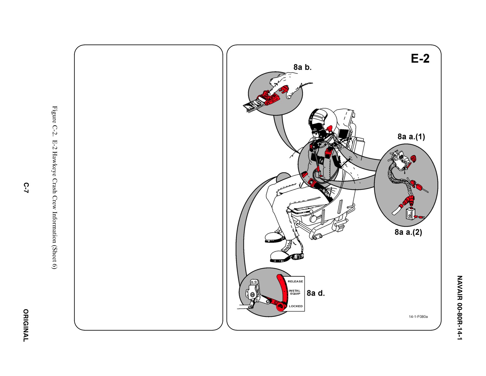
8a. CREW RELEASE (A/P22P-20 CREW
ą PARACHUTE BACKPACK ASSEMBLY)
ą1ą
Crewmembers are attached to the seats by the
use of a torso harness.
a.
PERSONNEL SERVICE, QUICK
DISCONNECT
(1) Remove oxygen mask by PULLING
DOWN on release tabs on either side of
mask.
(2) The communications leads are quick
disconnect. To release, PULL APART at
the quick disconnect fittings.
(3) Disconnect A/P22P-20 Emergency
Oxygen System from side of reulator by
turning CCW and pulling apart at
connection.
(4) Disconnect oxygen mask hose and
aircraft oxygen hose from reulator by
depressing and turning connector CCW
and pulling apart at connection. the
on-board oxygen hose will also be
disconnected during the performance of
this step.
b. RESTRAINT SUIT BELTS/RELEASE
Release two lap belt mini-Koch fittings, then
two shoulder harness Koch fittings.
c.
N/A
d. EMERGENCY RELEASE
Actuating the Emergency Release Handle
will free the crewmember from the seat.
However, the parachute and survival kit will
remain attached to the crewmember.
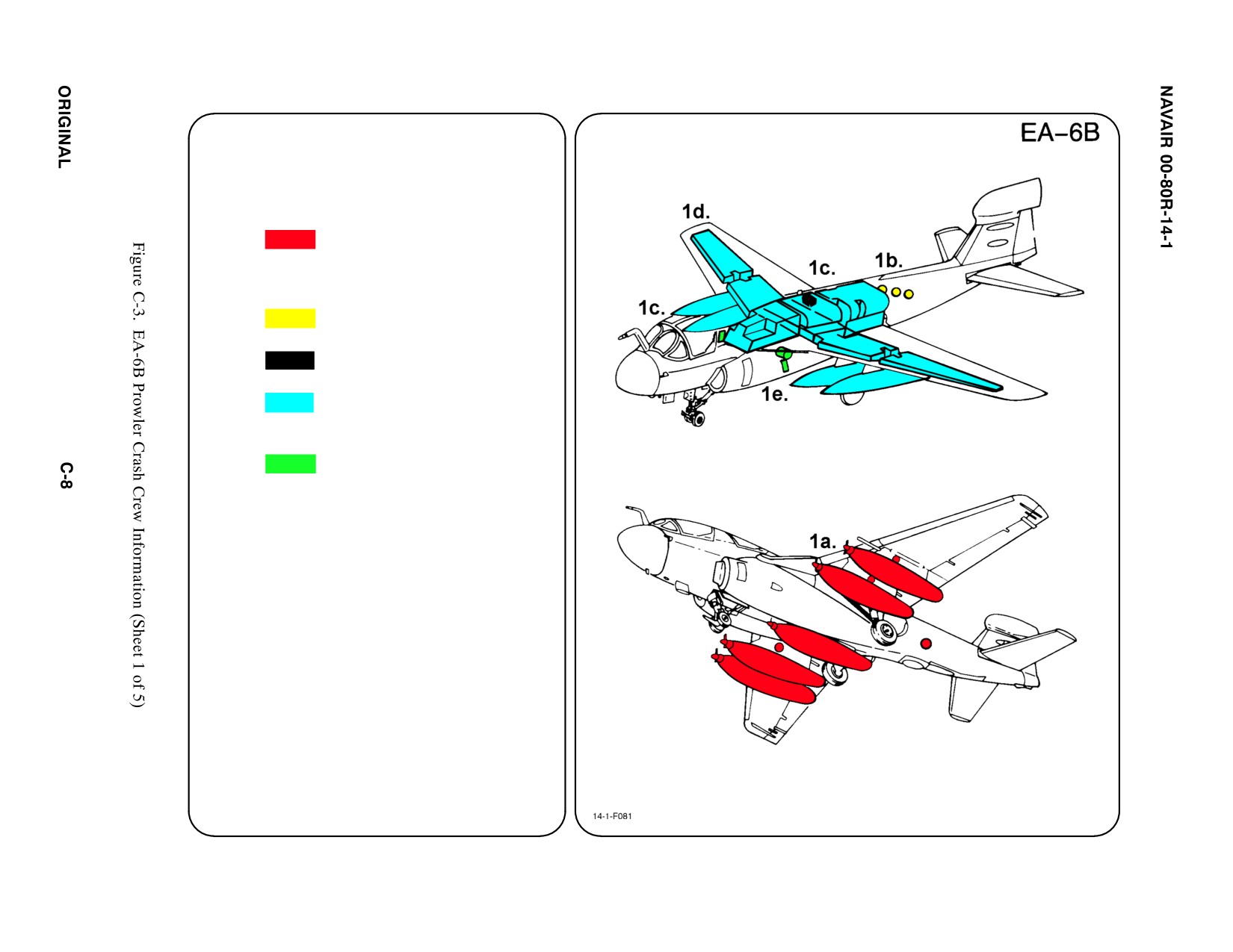
SPECIAL TOOLS/EQUIPMENT
Power Rescue Saw
Crash Axe
1. GENERAL AIRCRAFT INFORMATION
a. Armament
4 Wing Stations
1 Fus. Station
Chaff/Flares
Pylon Ejector Cartridges
b. Oxygen
Three 10 L Converters
c. Battery
1
d. Fuel
Internal — 2268 gal
External — 295 gal/droptank
e. Oil
Engine 3.9 gal
Hydraulic:
(Left) Combined — 13 gal
(Right) Flight — 5.6 gal
f. Pneumatic
System
3000 PSI
2.
AIRFRAME MATERIALS
a. N/A
b. Other
ąFiberglass
c. Steel
d. N/A
e. Aluminum
f. N/A
g. N/A
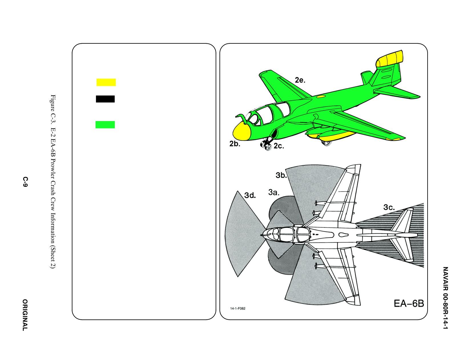
3.
AIRCRAFT DANGER AREAS
a. Inlet Suction — 25i
b. Turbine Blade Failure — 300i
c. Engine Exhaust — 300i
ąIdle — 80i
ąMax — 375i
d. Radiation
ąFWD 114_ Arc — 80i
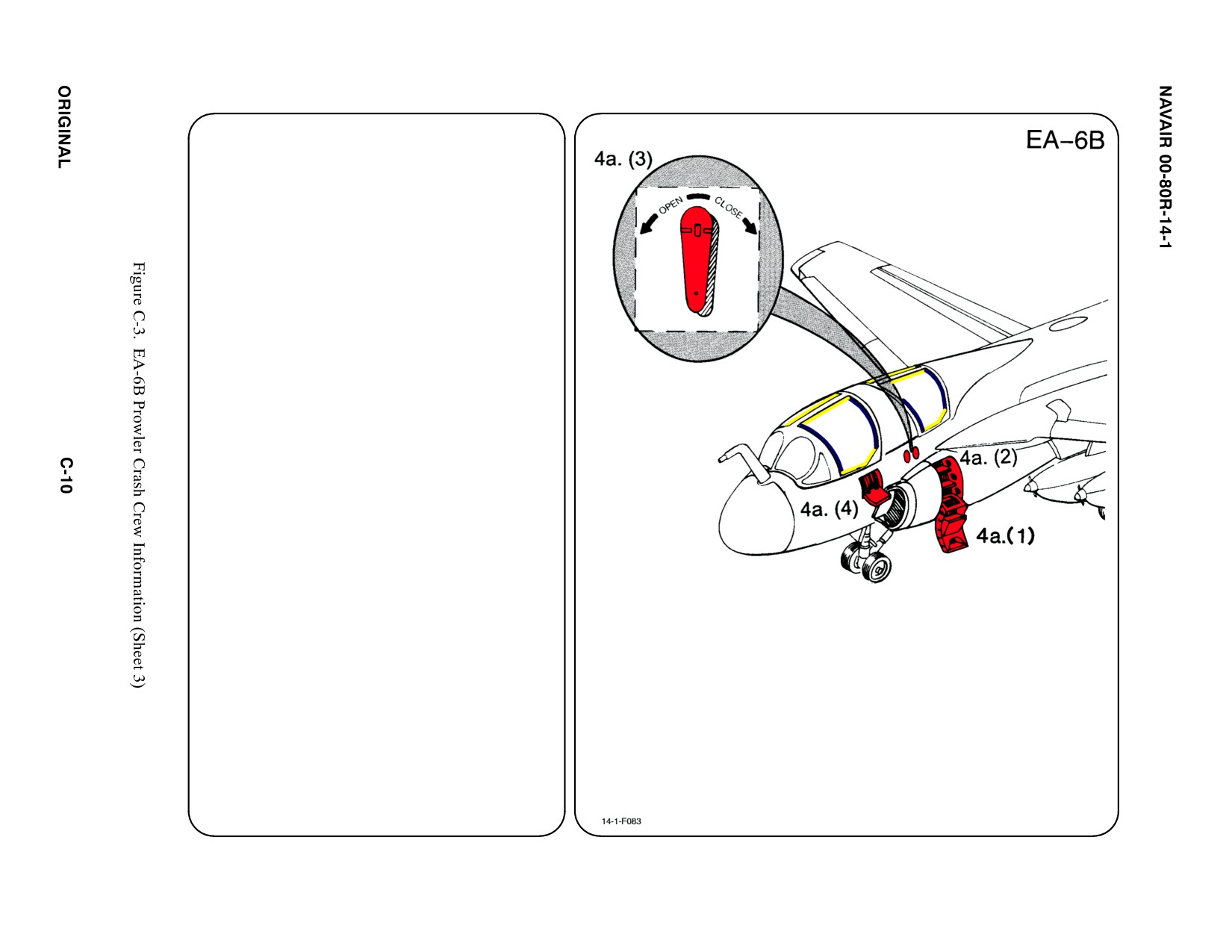
4. AIRCRAFT ENTRY
a. NORMAL ENTRY
(1) UNLATCH AND LOWER boarding
ladder.
(2) Raise and lock top step pushing up
thumb lock.
(3) Open canopies by pulling canopy control
handle out or detent and rotating
counterclockwise.
(4) To enter Forward cockpit, unlatch and
lower hinged boarding platform. Use as
a step.
b. N/A
c. N/A
d. FORCED ENTRY
Canopies are acrylic plastic and may be cut
with power rescue saw or crash axe. CUT
along canopy frames.
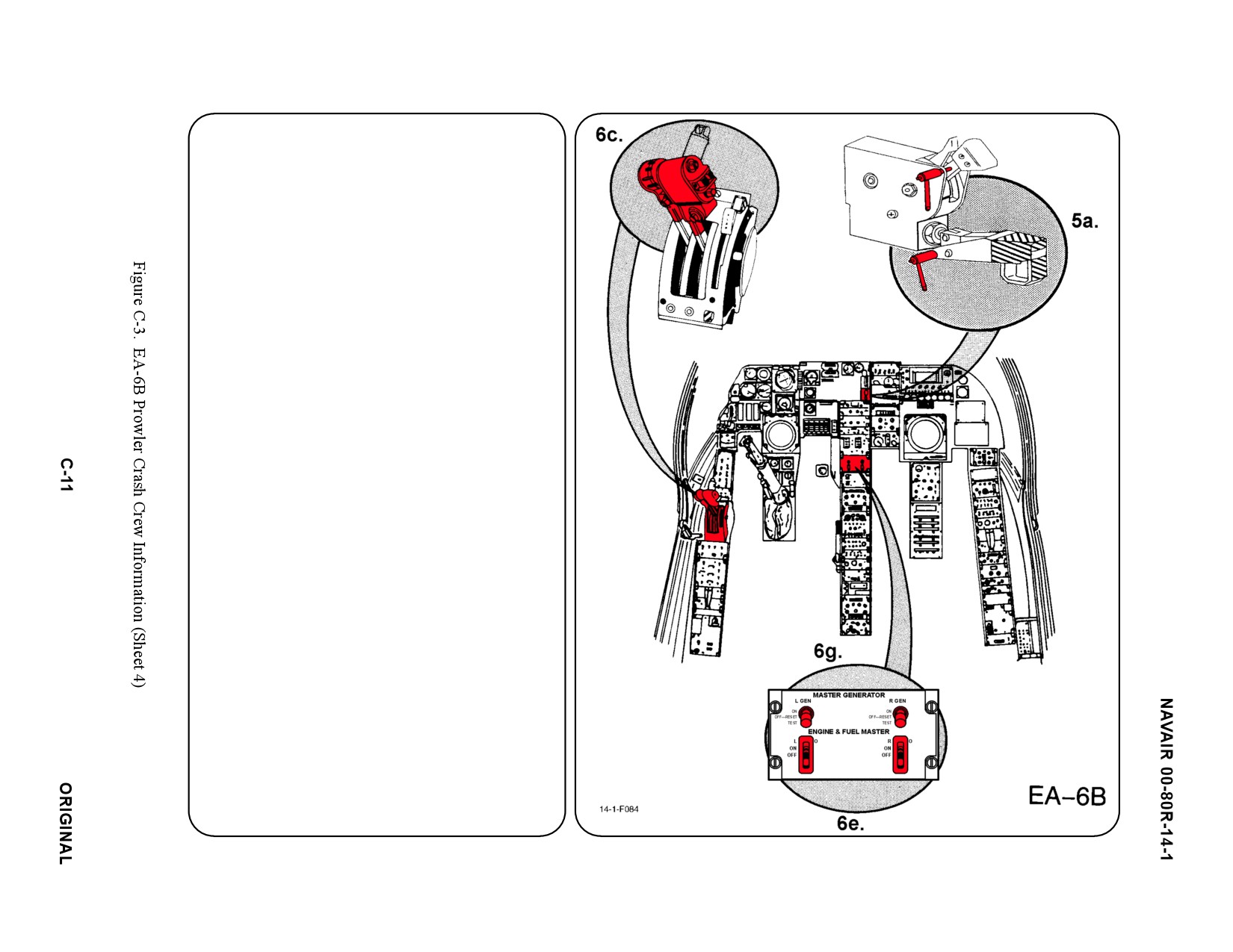
5.
CANOPY SAFETY
a. SAFETY LOCKPINS
Canopy may be made safe by INSERTING
Canopy Safety Lockpins in the following:
(1) FWD Canopy — Canopy Normal Handle
and Canopy Jettison Handle.
(2) AFT Cockpit — Canopy Normal Handle
and Canopy Jettison Handle.
b. N/A
6.
ENGINE SHUTDOWN
a. N/A
b. N/A
c. ENGINE POWER LEVERS
To secure the engines, RETARD Throttles
to the Idle Stop, then OUTBOARD (around
the horn) to OFF position.
Note
A
stop in the throttle quadrant prevents
simultaneous movement of both throttles to or
from the off position. Only one engine at a time
may be shut completely off.
d. N/A
e. ENGINE AND FUEL MASTER SWITCHES
PLACE Engine and Fuel Switches in OFF
position.
f. N/A
g. MASTER GENERATOR SWITCHES
PLACE Master Generator Switches in OFF
position.
7. N/A
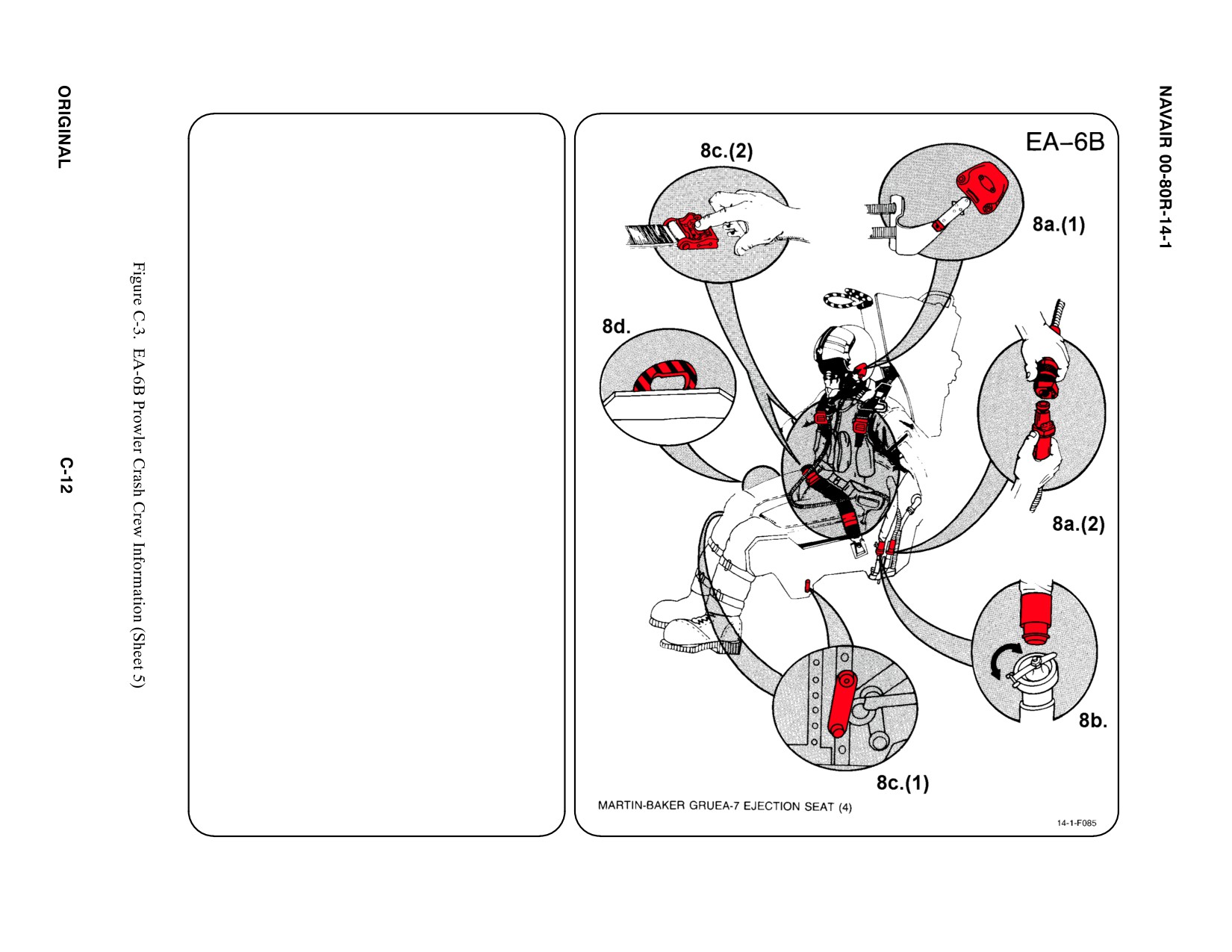
8.
CREW RELEASE
The pilot is attached to the seat by the use of
an integrated harness. Additionally, the oxygen/
communication lead is connected to the seat
pan. The anti-G suit hose is connected to an
outlet on the LH console.
a.
PERSONNEL SERVICE, QUICK
DISCONNECT
(1) Remove oxygen mask by pulling down
on the release tabs on either side of
mask.
(2) Disconnect oxygen/communication lead
from connection by pulling up on round
collar while pulling apart connection.
b. RESTRAINT SUIT BELTS/RELEASE
(1) Disconnect anti-G suit by pulling hose
from personnel services block
disconnect.
c.
HARNESS STRAPS/LEG RESTRAINT
RELEASE
(1) Release two leg restraint lines by pulling
the leg line snubber release lever
located on outer side of each snubber
box.
(2) Release two lap belt, than two shoulder
harnesses koch fitting.
d. EMERGENCY RELEASE
(1) Squeeze emergency restraint release
handle and rotate AFT. This release lap
belt, shoulder harness and leg restraint
lines. However, survival kit and para-
chute will remain attached to
crewmember.
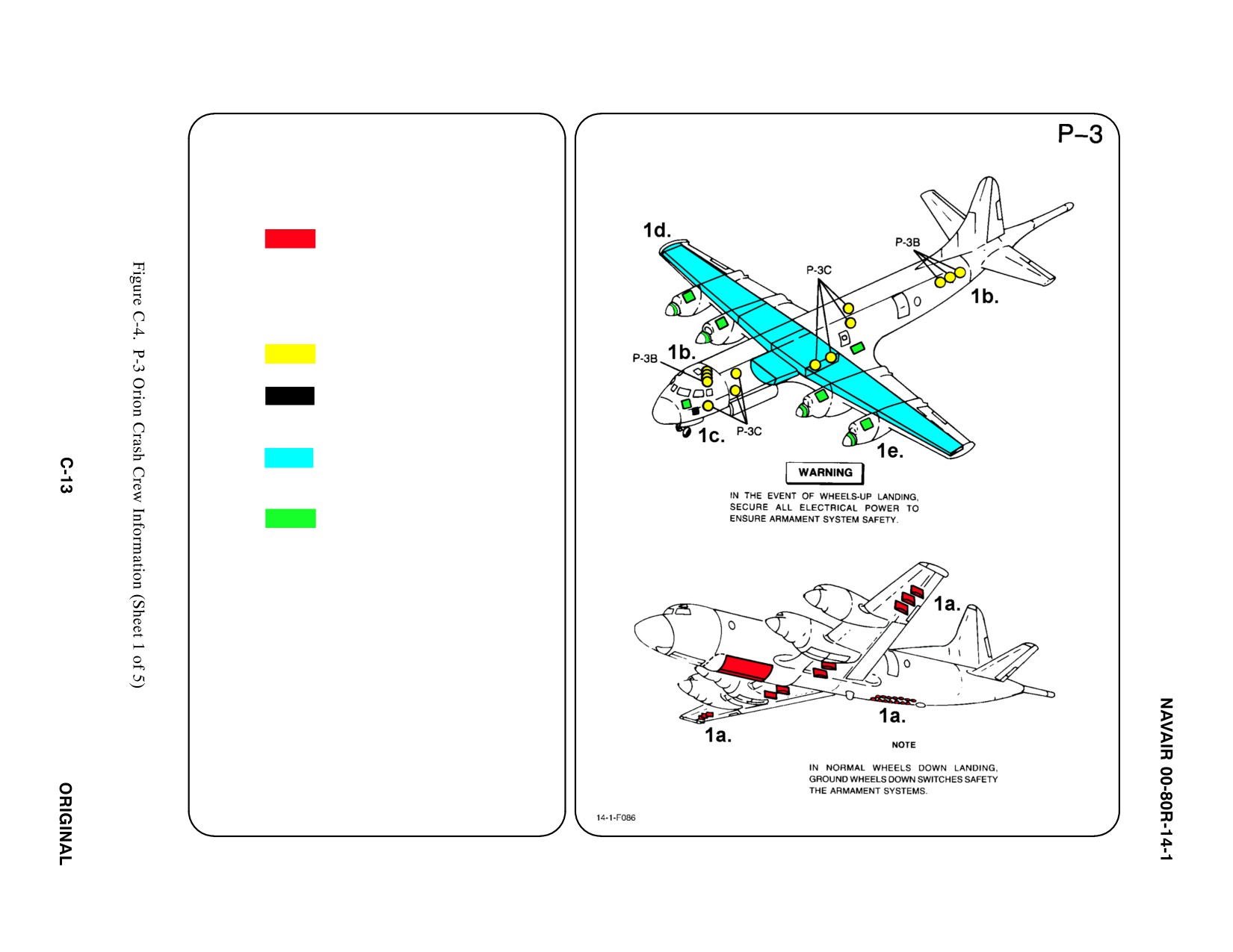
SPECIAL TOOLS/EQUIPMENT
Power Rescue Saw
Crash Axe
1. GENERAL AIRCRAFT INFORMATION
a. Armament
10 Wing Stations
8 Bomb Bay Stations
Sonobuoys/Flares
Photoflash Cartridges
Pylon Ejector
Cartridges
b. Oxygen/LOX
3 Fixed Cylinders
7 Portable Cylinders
c. Battery
1
d. Fuel
Internal 9200 gal
e. Oil
Engine 40 gal
Hydraulic 46.5 gal
f. Pneumatic
System
3000 PSI
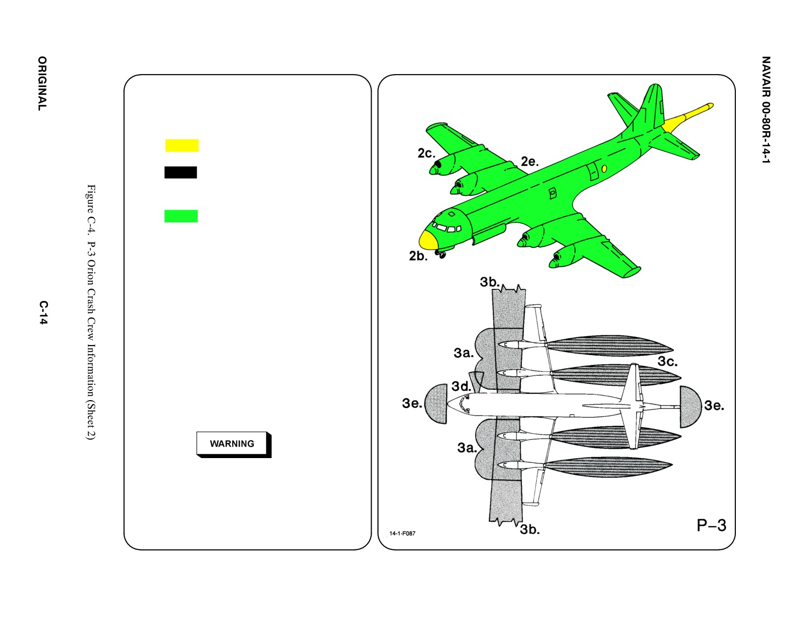
2.
AIRFRAME MATERIALS
a. N/A
b. Other
ąFiberglass
c. Steel
d. N/A
e. Aluminum
f. N/A
g. N/A
3.
AIRCRAFT DANGER AREAS
a. Propeller Danger Zone — 25i
b. Turbine Blade Failure — 300i
c. Engine Exhaust — 1500i
d. APU Exhaust — 15i
e. Radiation
ąAPS-115
ąąFWD 180_ Arc — 140i
ąąAFT 180_ Arc — 140i
ąAPS-137/APG-66
ąąFWD 180_ Arc — 250v
ąąAFT 180_ Arc — 250i
Since the antennas rotate 360_, the beam may
extend beyond the 180_ area shown. Safe
areas have not been determined.
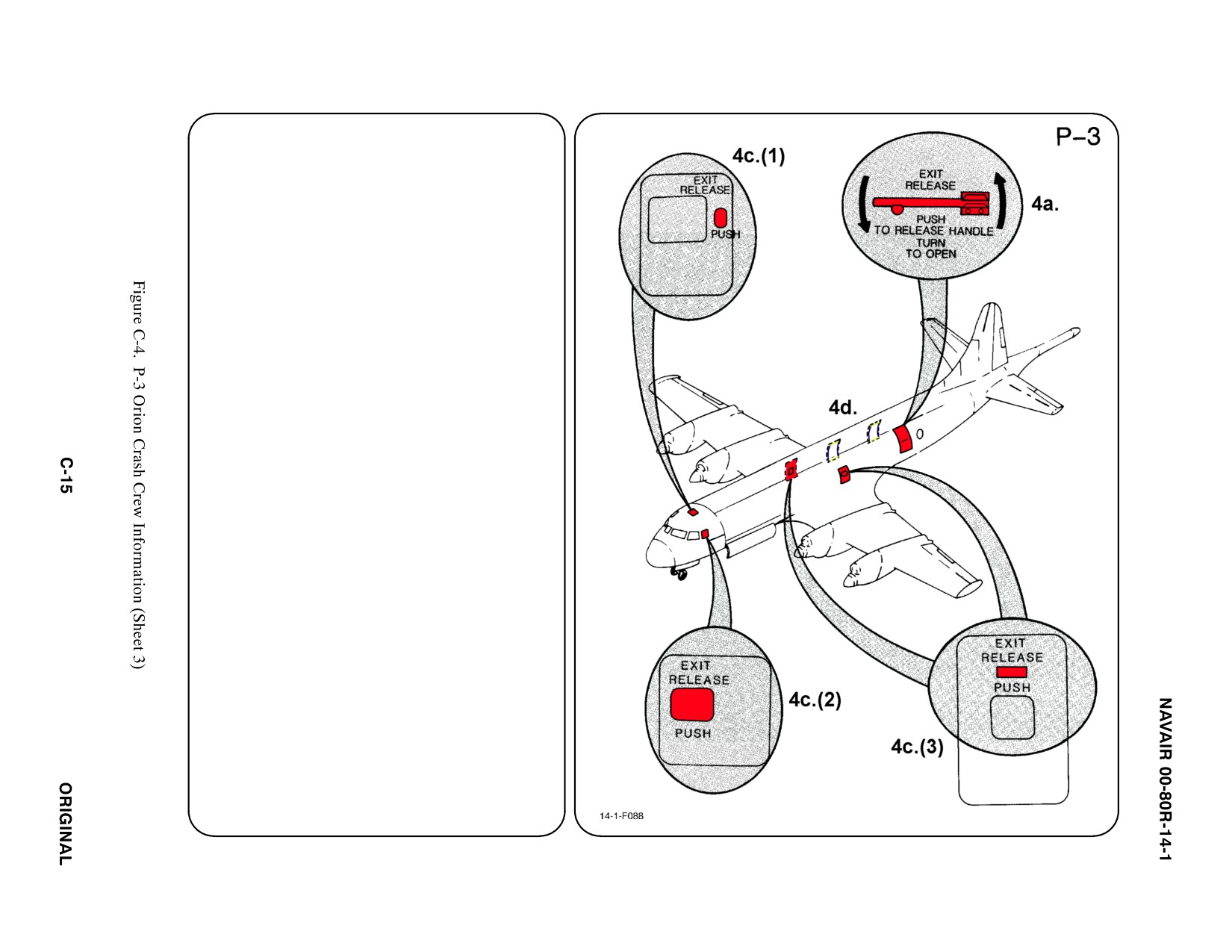
4.
AIRCRAFT ENTRY
a.
NORMAL ENTRY
Normal entrance is through AFT cabin door
on LH side of fuselage.
b. N/A
c.
EMERGENCY ENTRY
In event the Main Entrance Door is inac-
cessible, emergency entrance may be
gained through;
(1) Flight Station Escape Hatch, over
cockpit.
(2) Pilot's Auxiliary Exit, LH side of
fuselage just AFT of pilot's window.
(3) Overwing Emergency Exit Hatches,
both sides of fuselage.
d. FORCED ENTRY
CUT OUT entry areas as indicated in dia-
gram using power rescue saw or crash
axe.
5.
N/A
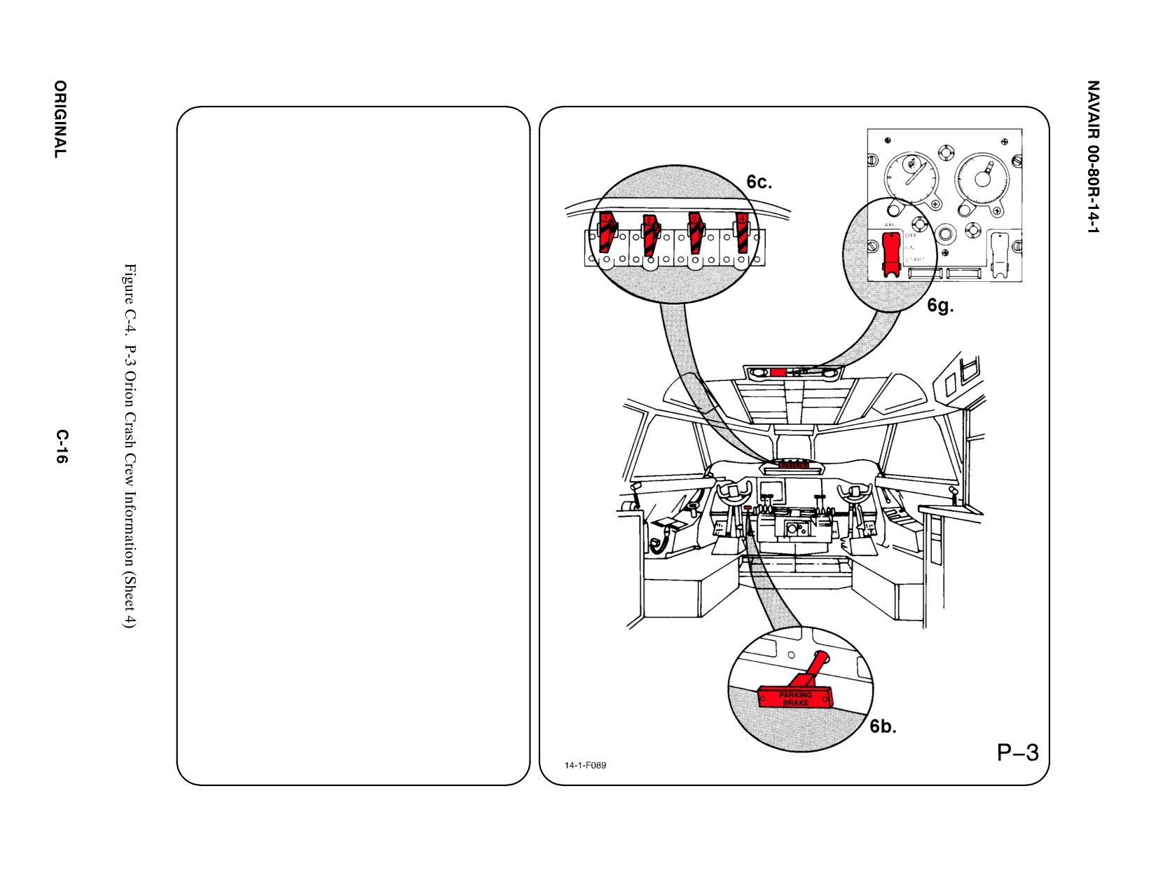
6.
ENGINE/APU SHUTDOWN
a. N/A
b. PARKING BRAKE
SET Parking Brake by DEPRESSING toe
pedals and PULLING Parking Brake
Handle.
c. EMERGENCY ENGINE SHUTDOWN
HANDLES
Pull all four Emergency Shutdown Handles.
d. N/A
e. N/A
f. N/A
g. AUXILIARY POWER UNIT (APU) SWITCH
PLACE APU Switch in OFF position. APUs
may be secured externally by a safety
switch located on LH side of fuselage FWD
of the APU.
Note
The APU Normal/Safe Switch also disables the
automatic fire extinguisher circuit.
7. BATTERY
Battery is located in nose wheelwell. To deac-
tivate battery, remove quick disconnect fitting.
a. N/A
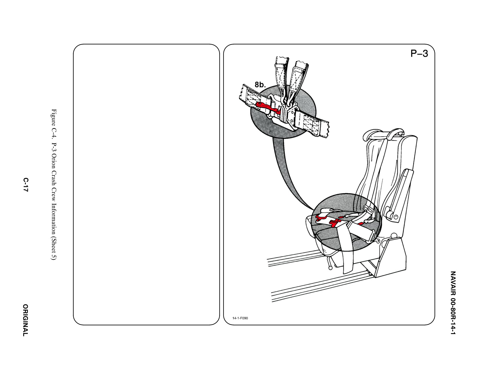
8. CREW RELEASE
The pilot, copilot, flight engineer, and radio
operator on the P-3B have shoulder har-
nesses and lap belts. All other crewmembers
have lap belts only.
The pilot, copilot, flight engineer, TACCO, Nav
Comm, and SS-3 on the P-3C have shoulder
harnesses and lap belts. All other crewmem-
bers have lap belts only.
a. N/A
b. RESTRAINT SUIT BELTS/RELEASE
Lift quick disconnect lever to release
shoulder harnesses and lap belt.
c. N/A
d. N/A
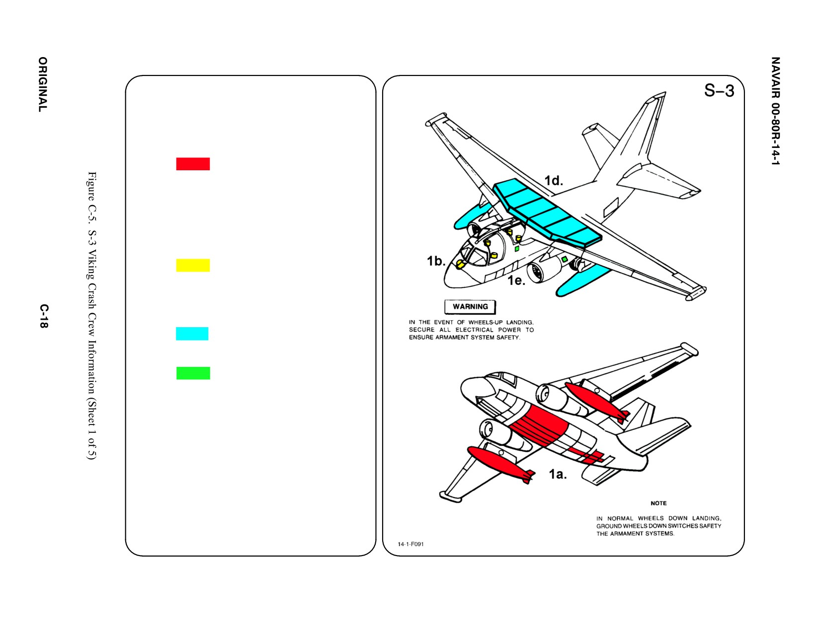
SPECIAL TOOLS/EQUIPMENT
Power Rescue Saw
Crash Axe
1. GENERAL AIRCRAFT INFORMATION
a. Armament
2 Wing Stations
2 Bomb Bays
with 4 Weapons
Stations
Sonobuoys
Pylon Ejector
Cartridges
b. Oxygen/LOX
10 L
c. N/A
d. Fuel
Internal 1933 gal
External 530 gal
e. Oil
Engine 2.4 gal
Hydraulic 7.2 gal
f. N/A
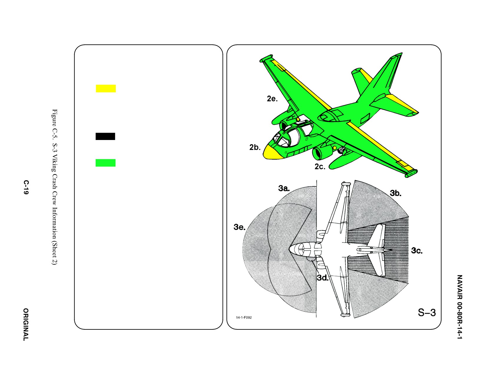
2. AIRFRAME MATERIALS
a. N/A
b. Other
Fiberglass/Magnesium
Note
Integrated drive generator castings are
magnesium.
c. Steel
d. N/A
e. Aluminum
f. N/A
g. N/A
3. AIRCRAFT DANGER AREAS
a. Inlet Suction — 26i
b. Turbine Blade Failure/Tire Explosion Hazard
c. Engine Exhaust
ąIdle — 50i
ąMax — 287i
d. APU Exhaust — 5i
e. Radiation
ąFWD 240_ Arc — 235i
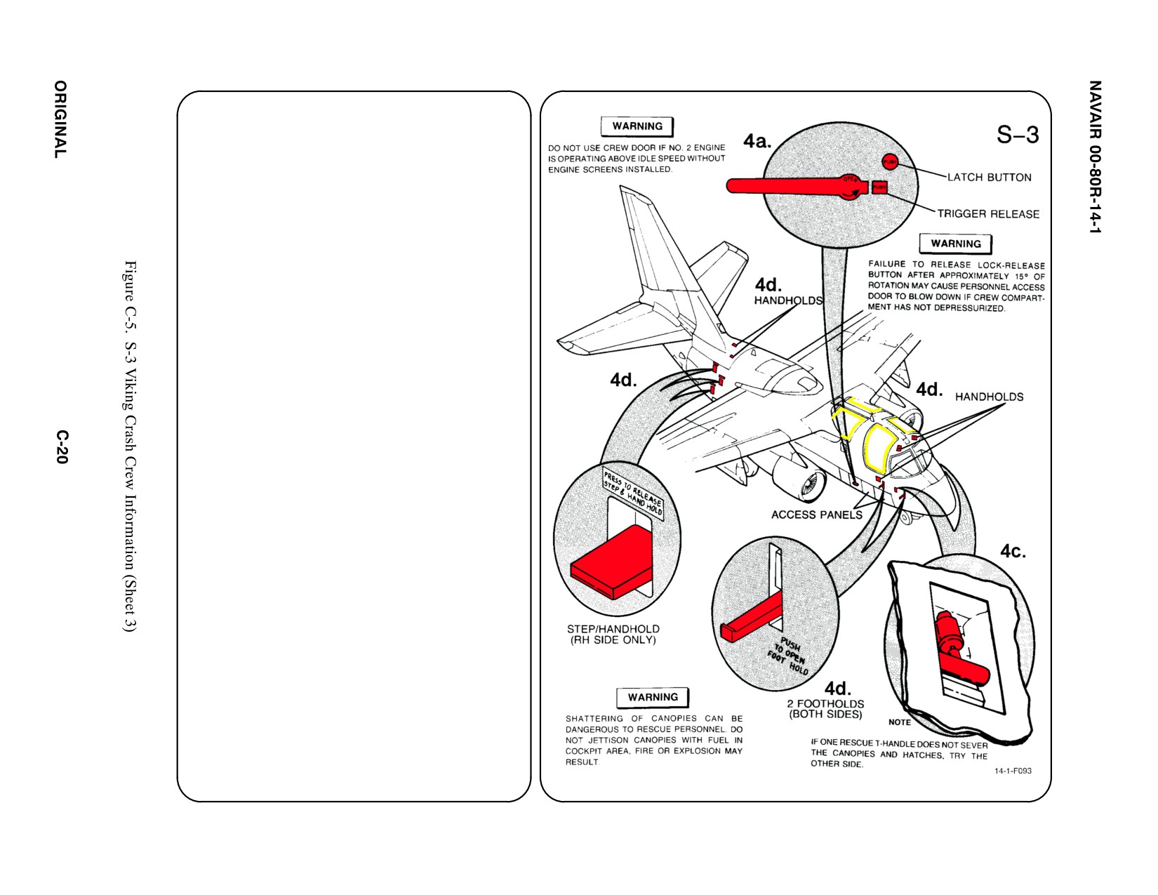
4.
AIRCRAFT ENTRY
a.
NORMAL ENTRY
Entry to cockpit is through personnel door on
RH side of fuselage.
(1) PRESS Trigger to release handle and
PRESS Latch Button. ROTATE
COUNTERCLOCKWISE 15_. RELEASE
Latch Button and ROTATE handle to the
UNLOCKED position.
(2) PUSH in handle. ROTATE CLOCKWISE
to stow, PRESS latch button and lower
door (use hand grip in middle step).
RAISE lift bar and ENGAGE door stop.
b. N/A
c.
EMERGENCY ENTRY
(Through the two FWD canopies and two aft
hatches) OPEN Rescue T-Handle Access
Door on either side of aircraft. Verify that all
rescue personnel are clear of all canopies
and hatches. PULL Hatch Severance
T-Handle away from aircraft and as far FWD
as possible (about 10 feet). Continue with
hard PULL; this will free the hatches and
canopies from the aircraft (pieces of debris
will be forced away from aircraft).
d. FORCED ENTRY
If normal or emergency entry procedures
cannot be accomplished, BREAK or CUT
through pilot or copilot/COTAC canopy or aft
hatches with axe or power rescue saw. CUT
along canopy frame. Manually remove can-
opies and hatch frames to clear opening. Use
Left and Right FWD Access Panels and
Footholds to reach the pilot and copilot/
COTAC. Use Right AFT fuselage Steps and
Handholds to reach the AFT hatch opening
and the two aft occupants.
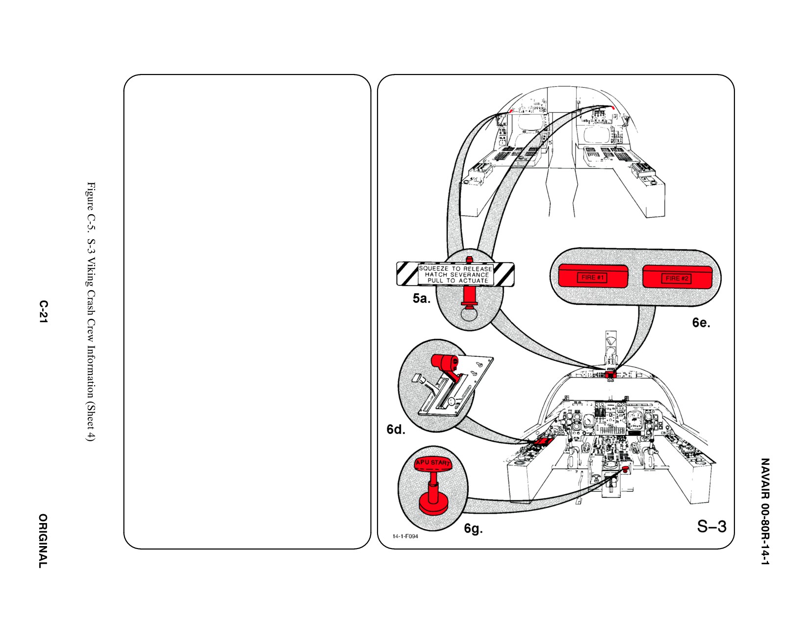
5.
CANOPY SAFETY
a. Canopy and hatches are equipped with a
mild explosive which uses a detonating cord
and a linear shaped charge. To safety
jettison system, INSERT safety pins in
Jettison Handles at 3 locations.
b. N/A
6.
ENGINE/APU SHUTDOWN
Engine may be shut down by throttles or fuel
system valves.
a. N/A
b. N/A
c. N/A
d. THROTTLES
MOVE Pilot's Throttles to OFF position
(move one at a time).
Note
Engines cannot be shut down with copilot's
throttles.
e. FUEL SHUTOFF VALVES
PULL Fire Handles 1 and 2 to shutoff fuel to
engines.
f. N/A
g. AUXILIARY POWER UNIT (APU)
PLACE APU T-Handle in OFF position.
7. N/A
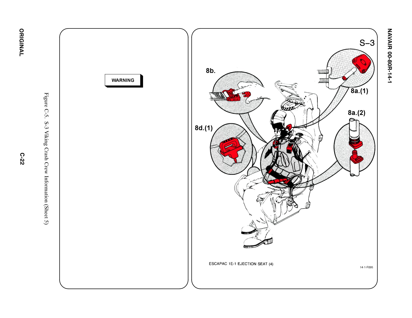
8. CREW RELEASE
The pilot is attached to the seat by the use of
an integrated harness. Additionally, the oxygen/
communication lead is connected to the seat
pan. The anti-G suit hose is connected to an
outlet on the LH console.
Inadvertent ejection of seat selected in
command-eject mode
(either pilot or
copilot/COTAC seat) will eject all four seats
regardless of the position of their individual
ejection seat safety levers.
a.
PERSONNEL SERVICE, QUICK
DISCONNECT
(1) Remove oxygen mask by pulling down
on the release tabs on either side of
mask.
(2) The oxygen/communication lead is
joined by a positive locking ring. To
release, pull up on round collar while
pulling apart connection.
b. RESTRAINT SUIT BELTS/RELEASE
(1) None
c.
HARNESS STRAPS/LEG RESTRAINT
RELEASE
(1) Release two lap belt, than two shoulder
harnesses koch fitting.
d. EMERGENCY RELEASE
(1) Actuating the emergency release handle
will free the crewmember fro the seat.
However, the parachute and survival kit
parachute will remain attached to
crewmember which increases difficulty
of removing crewmember if exit through
opposite canopy is required.
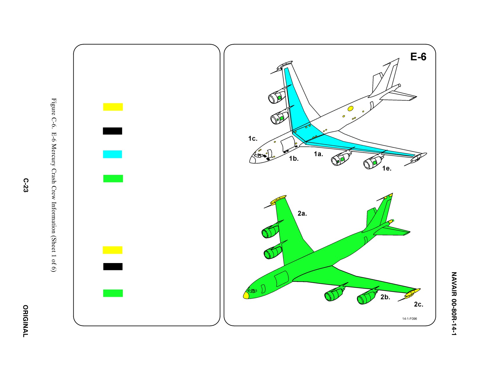
SPECIAL TOOLS/EQUIPMENT
Power Rescue Saw
Crash Axe
1. GENERAL AIRCRAFT INFORMATION
a. N/A
b. Oxygen/LOX
75 L LOX
18 Portable Bottles
c. Battery
7
d. Fuel
Internal 23,200 gal
e. Oil
Engine 54 gal
Hydraulic 72 gal
f. Pneumatic
System
3000 PSI
2. AIRFRAME MATERIALS
a. N/A
b. Other
Fiberglass
c. Steel
d. N/A
e. Aluminum
f. N/A
g. N/A
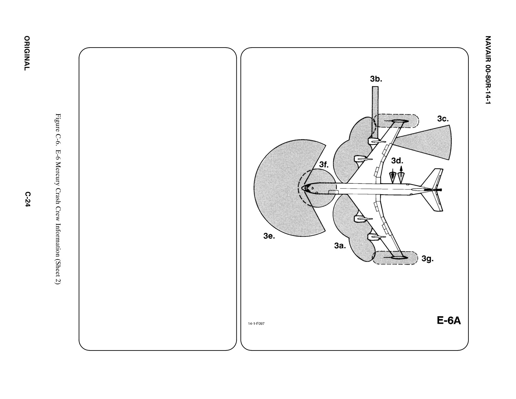
3. AIRCRAFT DANGER AREAS
a. Inlet Suction — 25i
b. Turbine Blade failure — 300i
c. Engine Exhaust — 500i
d. APU Intake and Exhaust — 25i
e. Radar Radiation FWD 240_ Arc — 60i
f. UHF Radiation 360_ Arc — 60i
g. HF Radiation 360_ Arc — 10i
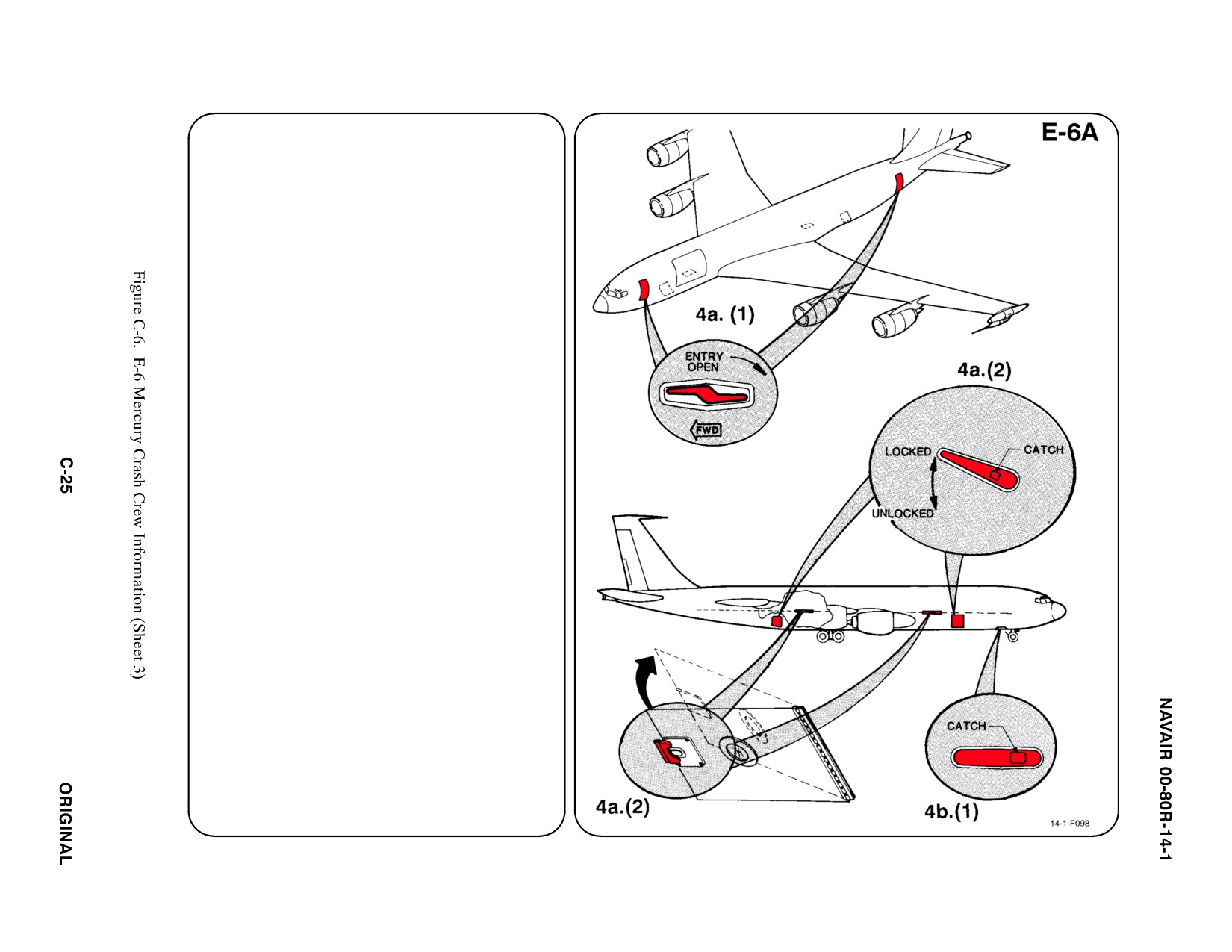
4.
AIRCRAFT ENTRY
a.
NORMAL ENTRY
Normal Entry to the main deck is through the
forward and aft main doors (LH side). Normal
entry to the forward and aft lower compart-
ments is through the forward and aft cargo
doors (RH side). The forward and aft lower
compartments also provide access to the
main deck through access hatches located
on the overhead of each compartment.
(1) PULL either Main Door Handle OUT and
ROTATE CLOCKWISE. RELEASE and
STOW Handle. PULL on AFT side of
door while PUSHING IN on FWD side
until door is parallel to aircraft and Door
Open Latch has caught.
(2) PRESS Catch on either FWD or AFT
Cargo Door Handle. ROTATE Handle
COUNTERCLOCKWISE, PUSH Door IN,
and SLIDE Door FWD. To access the
main deck, DEPRESS Latch on Access
Hatch and PUSH UPWARD on bottom of
Hatch until Uplock is engaged.
Note
To gain entry to the main deck from the radio
access door, proceed through compartment
and open hatch to the main deck, see 4a(2).
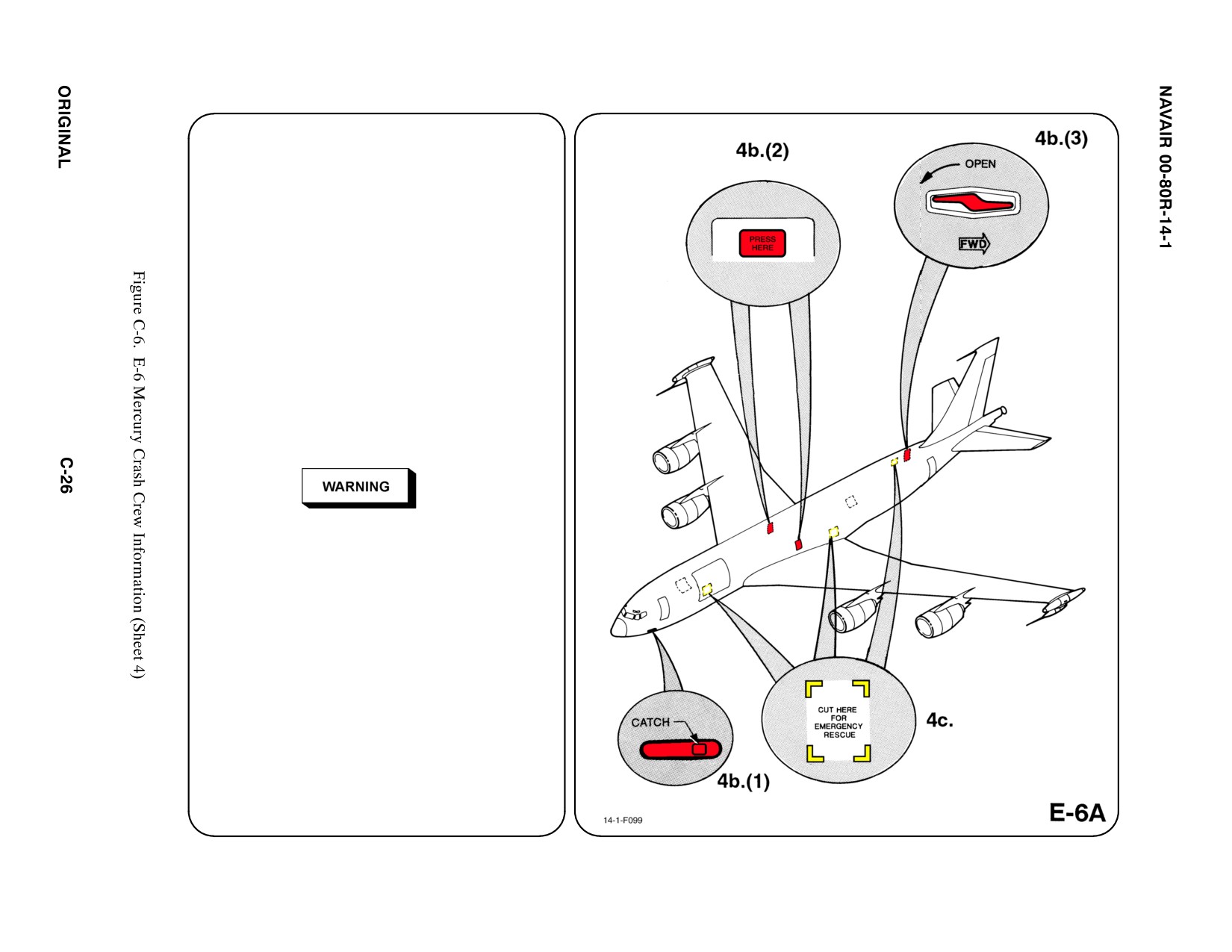
ą4. AIRCRAFT ENTRY (CONT.)
b. N/A
c. EMERGENCY ENTRY
(1) Radio Access Door. PRESS catch to
release Handle. ROTATE Handle
COUNTERCLOCKWISE and PUSH
door INWARD.
(2) Emergency Exit Hatches. PUSH
Panel INWARD to unlatch. PUSH
Hatch INWARD and LIFT UPWARD.
Hatch weighs about 50 pounds.
(3) Bailout Door. PULL Door Handle OUT
and ROTATE COUNTERCLOCK-
WISE. PUSH door INWARD. Door is
free-standing and weighs about 69
pounds.
If the FORWARD or AFT doors to the main
decks on the left hand side are opened from the
outside, escape slides will deploy if they have
not been disconnected from the inside.
CUT OUT entry areas as indicated on dia-
gram using power rescue saw or crash
axe.
d. N/A
5. N/A
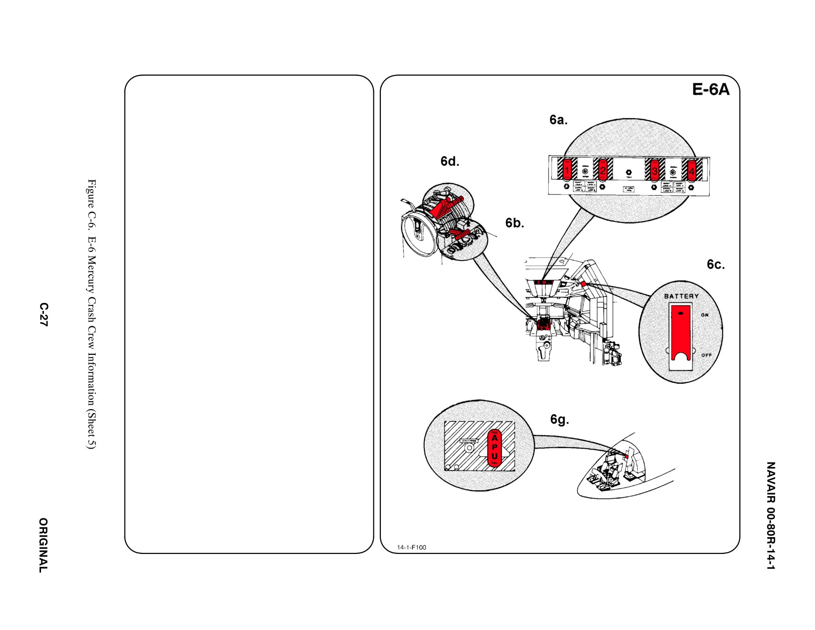
6.
ENGINE/APU SHUTDOWN
a. ENGINE FIRE SWITCHES
PULL Engine Fire Switches.
b. START LEVERS
PULL Start Levers AFT and PLACE in
FULL DOWN position.
c. BATTERY
LIFT Red Guard UP and PLACE Battery
Switch DOWN in OFF position.
d. THROTTLES
RETARD Throttles to FULL AFT position.
e. N/A
f. N/A
g. AUXILIARY POWER UNIT (APU)
PULL APU Fire Switch.
7.
BATTERIES
Batteries are located in the FWD Lower
Compartment accessible through the Radio
Access Door, labeled Battery Access. To fur-
ther deactivate batteries, REMOVE Quick
Disconnect Fittings, time permitting.
a. N/A
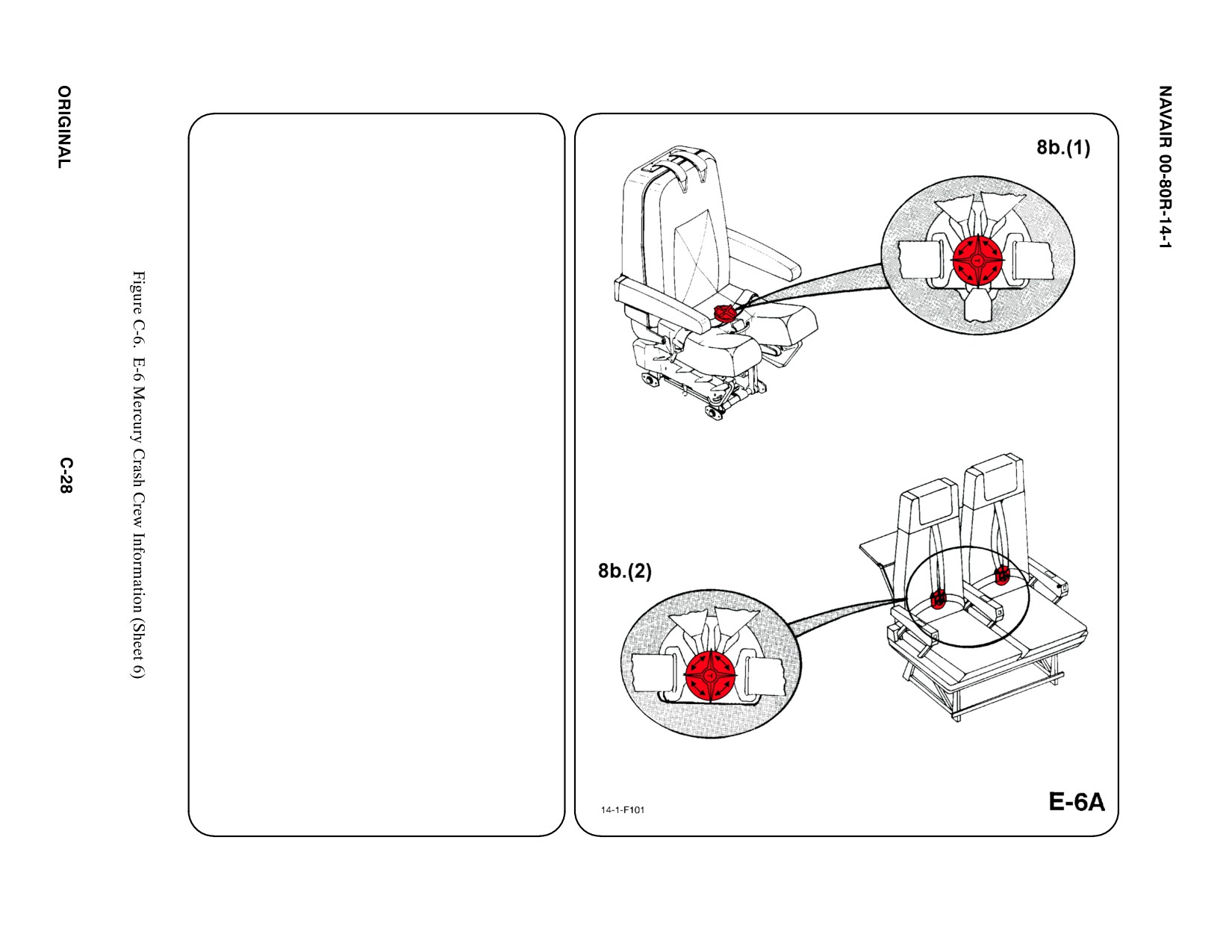
8.
CREW RELEASE
All crewmembers are attached to the seats by
shoulder harnesses secured to lap belts
equipped with quick disconnect buckles (rotary
type). Aft facing crew rest seats are not
equipped with shoulder harnesses; forward
facing seats are so equipped. Both have quick
disconnect buckles similar to the pilot seat.
a. N/A
b. RESTRAINT SUIT BELTS/RELEASE
(1) Rotate Rotary Release Buckle in either
direction to release shoulder harness, lap
belt and crotch strap.
(2) CREW REST SEATS; Rotate Rotary
Release Buckle in either direction to
release shoulder harness and lap belt on
FWD facing seats or lap belt only on Aft
facing seats.
c. N/A
d. N/A
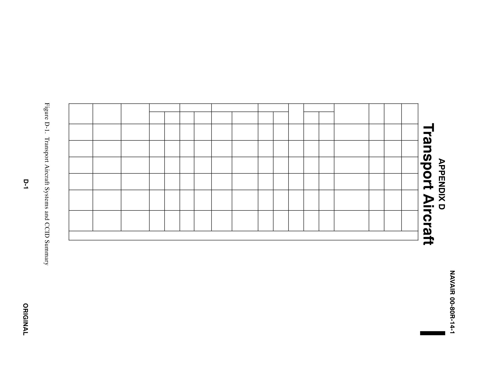
TRANSPORT AIRCRAFT SYSTEMS
AND
CRASH CREW INFORMATION DIAGRAMS SUMMARY
FUEL (GAL)
OIL (GAL)
OXYGEN
PNEU SYS
ORDNANCE
AIRFRAME
FWD
FREE
EJECT
TYPE
NAME
MATERIALS
INT
EXT
ENG
HYD
LOX
BOTTLE
GAS
AIR
GUN
FIRE
FALL
PYROTECHNICS
BTRY
SYS
S.O.B.
ALUMINUM
N2
C-2
GREYHOUND
STEEL
1824
NONE
36
19.8
20L
2 PORT
3000
NONE
NONE
NONE
NONE
SIGNAL FLARES
1
NONE
30
FIBERGLASS
PSI
ALUMINUM
24.6
N2
C-9
SKYTRAIN II
STEEL
5929
NONE
10
15
35L
3000
NONE
NONE
NONE
NONE
SIGNAL FLARES
2
NONE
97
IN3 SYS
FIBERGLASS
PSI
ALUMINUM
1 PT (B)
U/RC-12
SUPER
STEEL
544
NONE
6
3.5 GAL
NONE
49 IN3
NONE
NONE
NONE
NONE
NONE
NONE
1
NONE
10
KING AIR
FIBERGLASS
(F/M)
ALUMINUM
25L LOX
N2
C/KC-130
(4)
HERCULES
STEEL
6826
2810
48
29.6
C/KC-130
3000
NONE
NONE
NONE
NONE
SIGNAL FLARES
2
NONE
100
F/R/T/J
PORT
FIBERGLASS
T/J only
PSI
ALUMINUM
C-20D
GULFSTREAM
STEEL
(2) 77 FT
3
N2
(21)
C-20D/G
4134
NONE
3.8
6.7
NONE
3000
NONE
NONE
NONE
NONE
NONE
2
NONE
III/IV
GRAPHITE
(2) 115 FT3
C-20G
PSI
EPOXY
(30)
2
ALUMINUM
AFT/FORWA
UC-26
METRO-LINER
STEEL
648
NONE
8
TBD
NONE
NONE
NONE
NONE
NONE
NONE
NONE
2
NONE
20
RD 1850 IN
FIBERGLASS
SYS
*Fuselage tank if installed adds - 3587 gal to internal fuel.
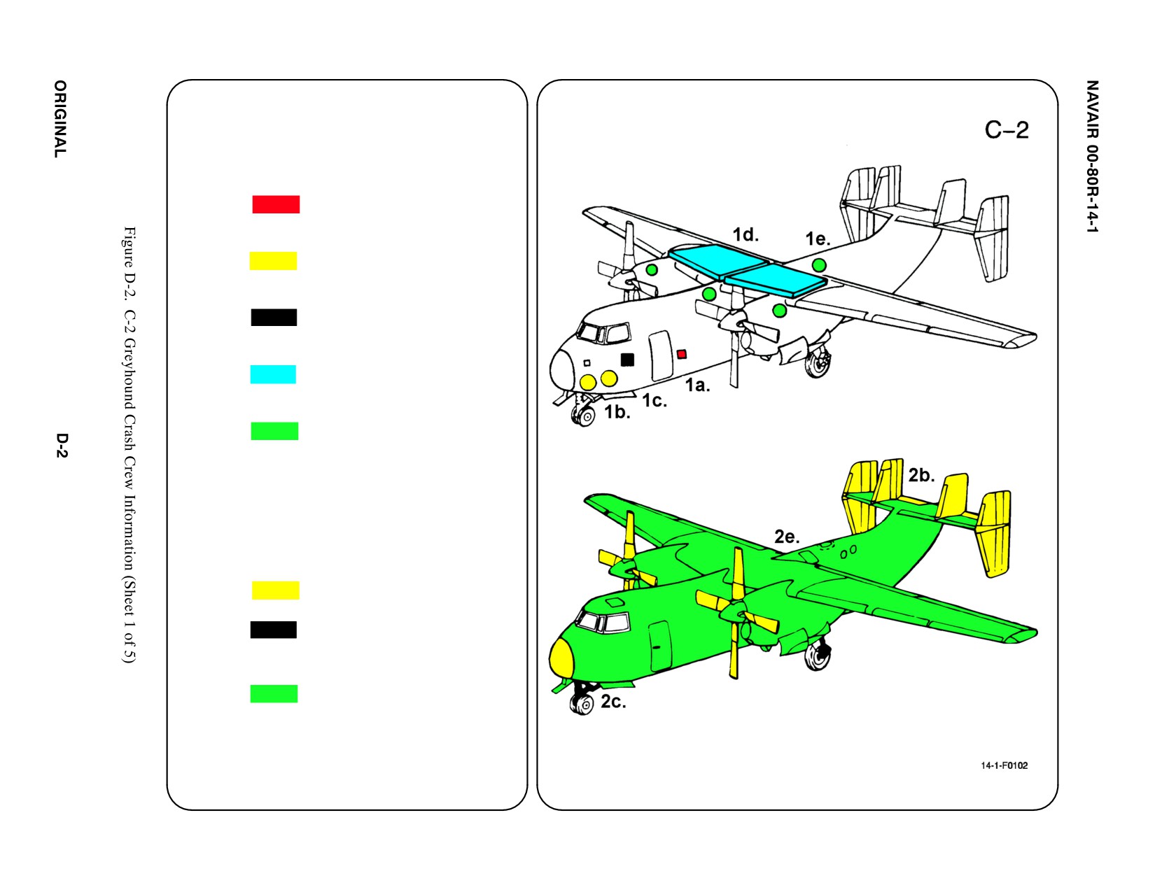
SPECIAL TOOLS/EQUIPMENT
Power Rescue Saw
Crash Axe
1. GENERAL AIRCRAFT INFORMATION
a. Pyrotechnics
Signal Flares
b. Oxygen/LOX
20L
c. Battery
1 (Starboard Side)
d. Fuel
Internal 1824 gal
e. Oil
Engine 36 gal
Hydraulic 19.83 gal
f. Pneumatic
ąSystem
3000 PSI
2. AIRFRAME MATERIALS
a. N/A
b. Other
ąFiberglass/Magnesium
c. Steel
d. N/A
e. Aluminum
f. N/A
g. N/A
Note
Reduction gear behind engine propellers are
approximately 80% magnesium.
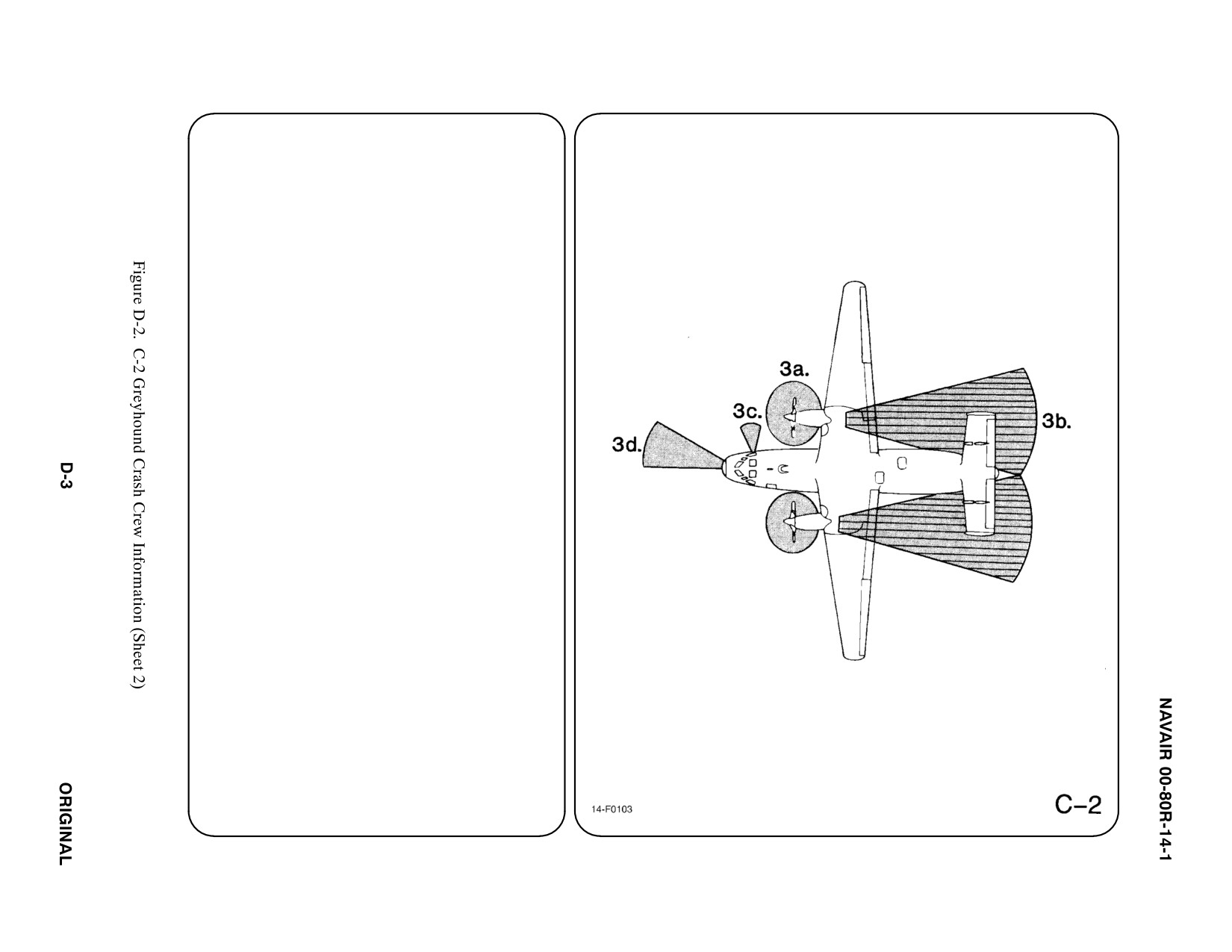
3. AIRCRAFT DANGER AREAS
a. Propeller Danger Zone — 15i
b. Propeller Blast
ąIdle — 24i
ąMax — 28i
c. APU Exhaust
d. Radiation
ąFWD 1200 Arc — 21i
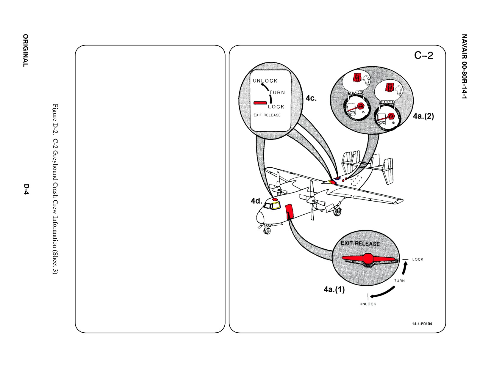
4. AIRCRAFT ENTRY
a. NORMAL ENTRY
(1) Enter the flight deck through the Main
Entrance Door on LH side of fuselage.
TURN Release Handle to UNLOCK and
PULL door OUT and DOWN.
(2) Enter the Cargo/Passenger
Compartment through the ramp. If ramp
is closed and hydraulic power is
available, OPEN access covers to
selector valve on AFT RH side of
fuselage. PLACE Cargo and Ramp
Selector Valve Handle to RAMP OPEN
position. With ramp level, PLACE Ramp
Loading Selector Valve Handle to RAMP
GROUND position to lower ramp.
Note
Cargo doors and ramp will open and ramp will
stop in level position. Releasing handle will stop
opening cycle at any point.
b. N/A
c. EMERGENCY ENTRY
Access may be gained through FWD and
AFT Emergency Escape Hatches on top of
fuselage.
d. FORCED ENTRY
If the main entrance, cargo door and ramp
are inaccessible, CHOP or SAW around
pilot or copilot's side windows where
indicated. Access to the cargo or passenger
compartment is available, CHOP or SAW
out AFT escape hatch.
5. N/A
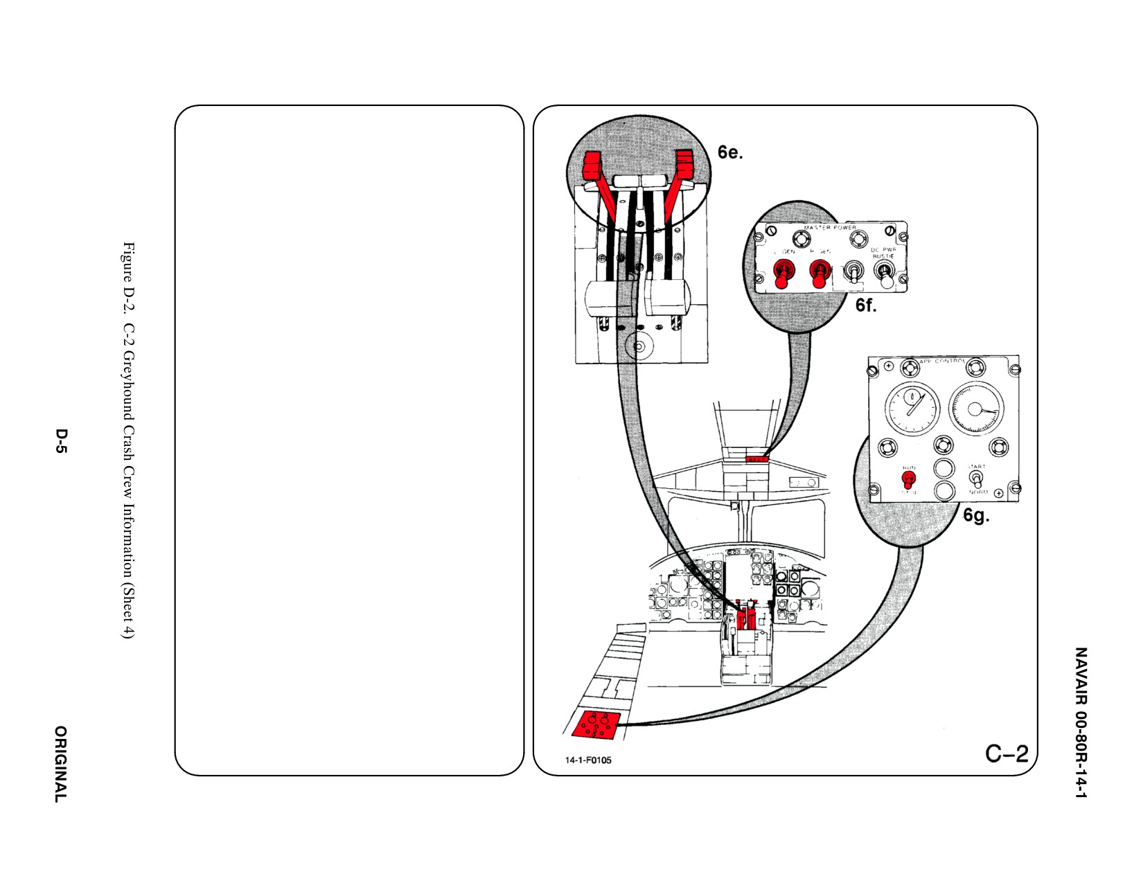
6.
ENGINE/APU SHUTDOWN
a. N/A
b. N/A
c. N/A
d. N/A
e. CONDITION LEVER
DEPRESS trigger lock on UNDERSIDE of
Condition Lever Handles and MOVE levers
to extreme AFT position.
f. GENERATORS
Place Left and Right Generator Switches in
OFF position.
g. AUXILIARY POWER UNIT CONTROL
(APU)
PLACE the Run/Stop Switch in STOP
position.
7.
BATTERY
The battery is for the APU only and is located
FWD and below the copilot's compartment.
a. N/A
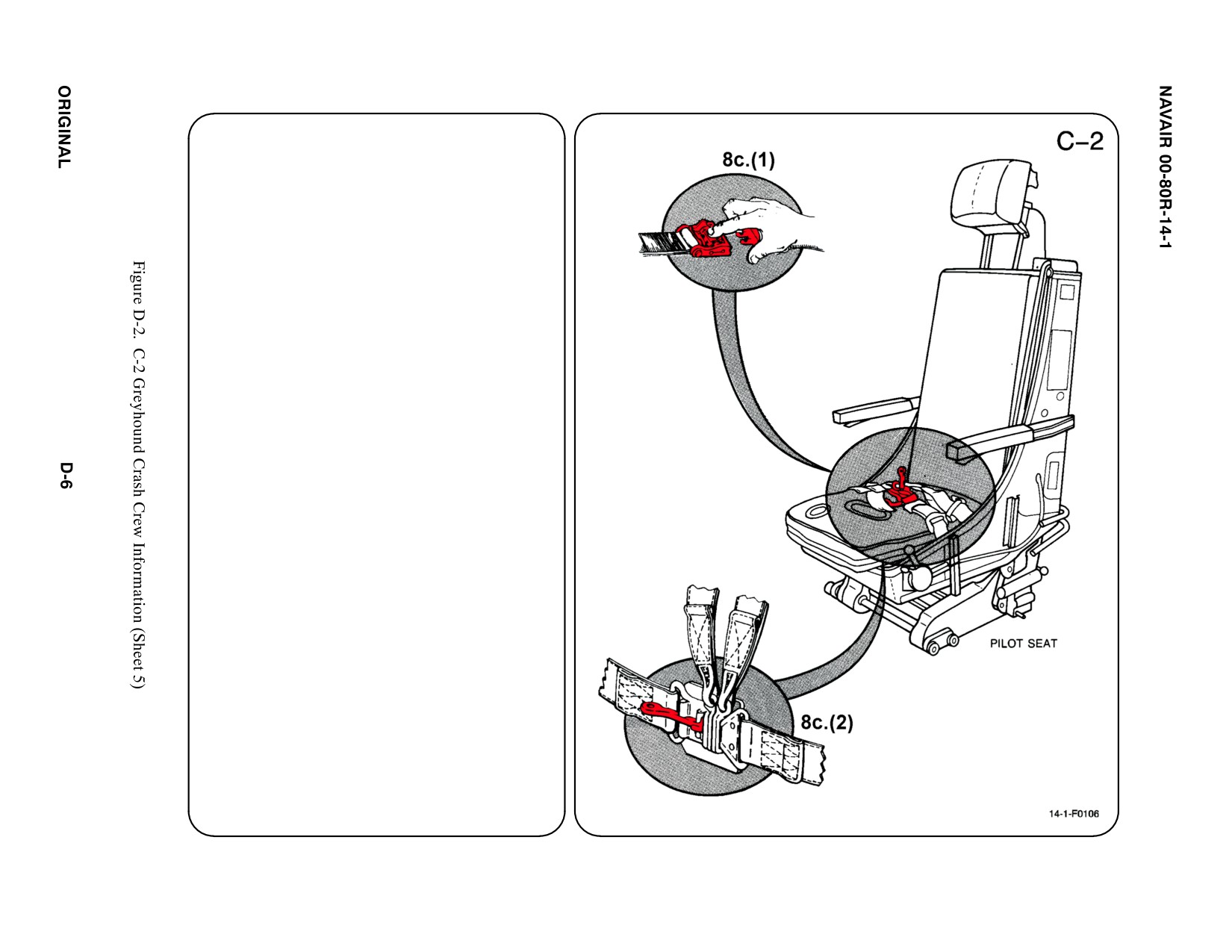
8. CREW RELEASE
The pilot/copilot's seats may be equipped with
standard shoulder straps and lap belts or
equipped for use with an integrated harness.
All other seats are equipped with standard
shoulder harnesses and lap belts.
a. N/A
b. N/A
c. RESTRAINT SUIT BELTS/RELEASE
(1) Release two lap belt, then two shoulder
harness koch fittings.
(2) SHOULDER HARNESS/LAP BELT —
LIFT quick disconnect lever to release
shoulder harnesses and lap belt.
d. N/A
SPECIAL TOOLS/EQUIPMENT
Power Rescue Saw
Crash Axe
1. GENERAL AIRCRAFT INFORMATION
a. N/A
b. Oxygen/Gas
35 L LOX
24.6 in3
c. Battery
2
d. Fuel
Internal 5929 gal
e. Oil
Engine 10 gal
Hydraulic 15 gal
f. Pneumatic
3000 PSI
ąSystem
2. AIRFRAME MATERIALS
a. N/A
b. Other
ąFiberglass
c. Steel
d. N/A
e. Aluminum
f. N/A
g. N/A
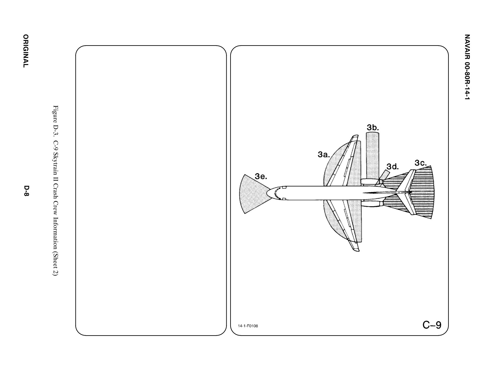
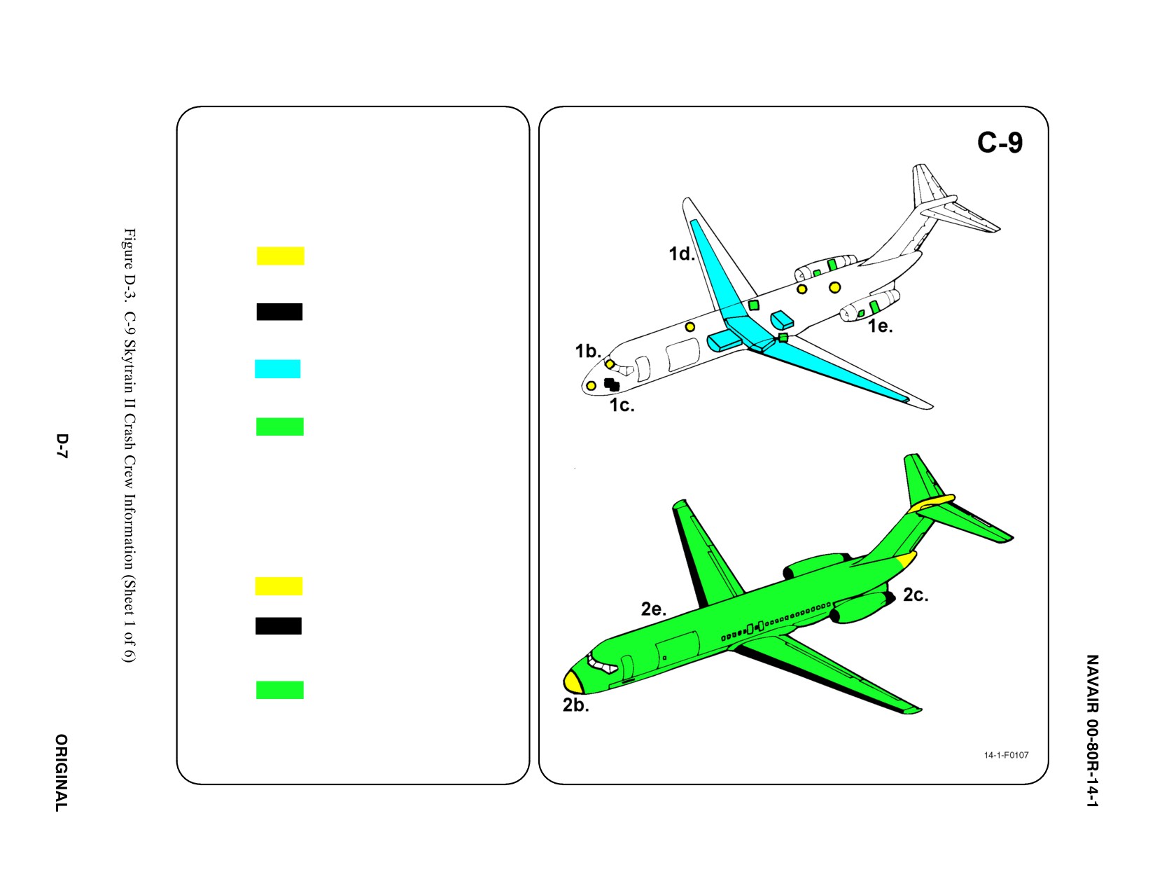
3. AIRCRAFT DANGER AREAS
a. Inlet Suction — 25i
b. Turbine Blade Failure — 300i
c. Engine Exhaust — 350i
d. APU Exhaust — 8i
e. Radiation
ąFWD 140_ Arc — 21i
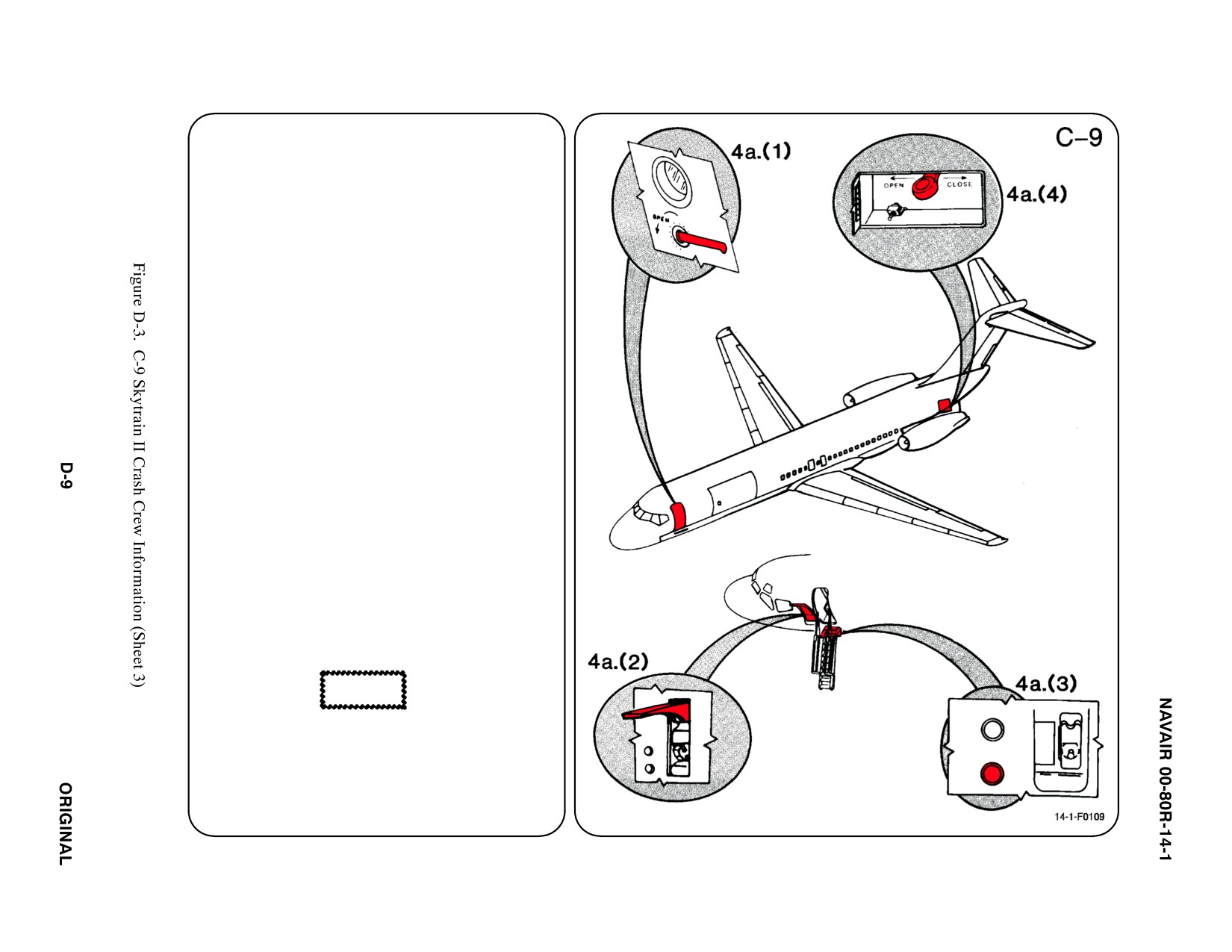
4. AIRCRAFT ENTRY
a. NORMAL ENTRY
Normal entry to the flight compartment,
and passenger and/or cargo compartment
is through the FWD entrance door, service
entrance door, main cargo door, and
pressure bulkhead door.
(1) PULL FWD Entrance Door Handle
(FWD LH side of fuselage) OUT and
ROTATE COUNTERCLOCKWISE.
Service door is located on RH side of
fuselage, PULL handle and ROTATE
CLOCKWISE.
(2) LIFT Stairwell External Door Handle,
located below FWD entrance door, and
RAISE to UP position.
(3) DEPRESS lower button marked DN to
EXTEND stairwell ladder.
Note
If aircraft is shut down, auxiliary power switch
under latch handle must be held in the ON
position while depressing DOWN button.
(4) Open Rear Stairway Control Panel,
located on AFT LH exterior fuselage,
PUSH control handle FWD to OPEN
position to release stairway, HOLD until
stairway is fully OPEN.
CAUTION
Stairway free falls to down position.
b. N/A
123
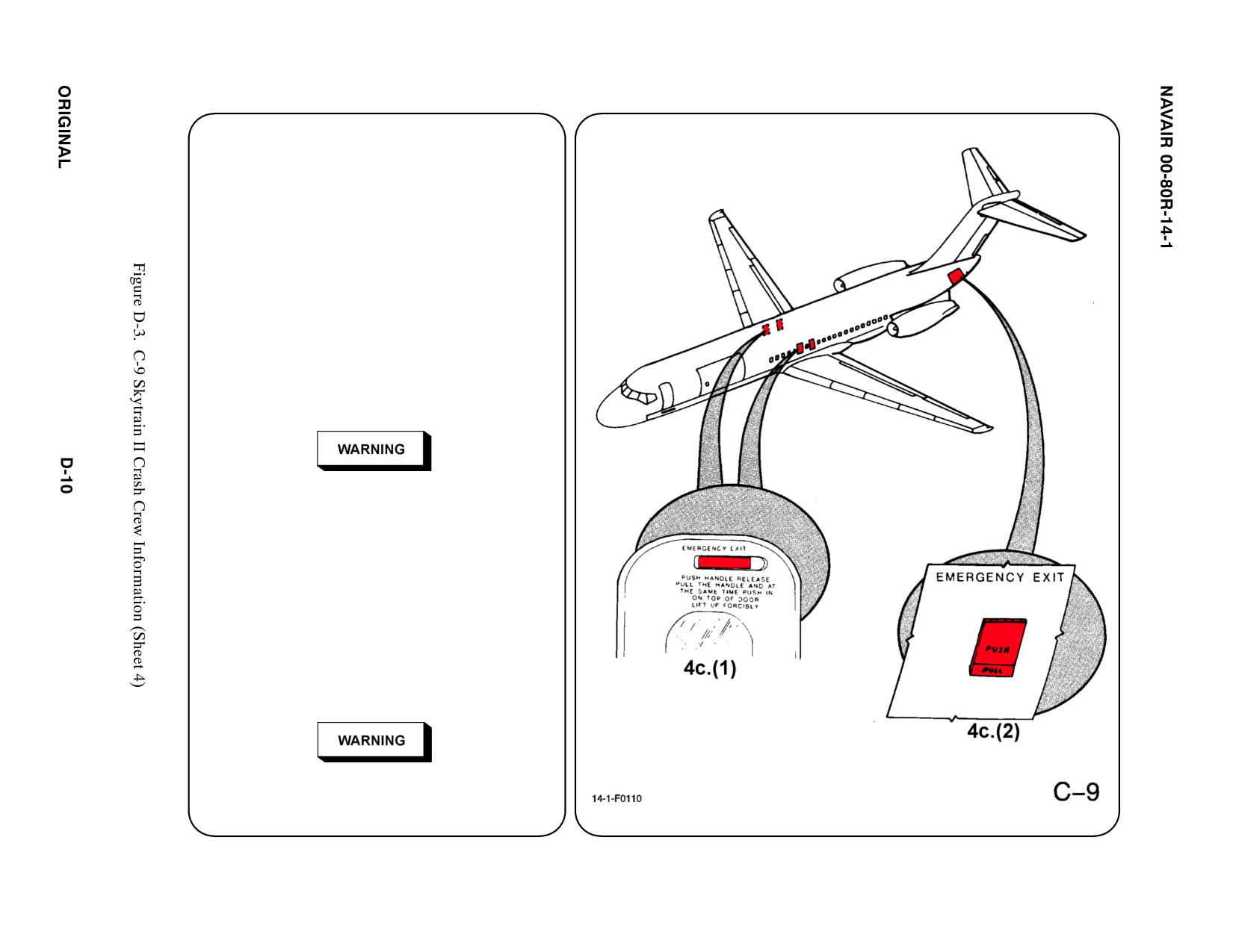
4. AIRCRAFT ENTRY (CONT.) ab
c. EMERGENCY ENTRY
If normal entry doors are inaccessible, entry
may be obtained through the overwing
emergency entry doors, the jettisonable tail
cone area, and the clear view windows.
(1) PUSH Overwing Exit Door Handle (two
doors are located over each wing),
PULL handle to unlatch door, PUSH IN
and LIFT UP forcibly.
(2) PUSH IN Jettisonable Tail Cone
T-Handle door, located on fuselage
FWD of tail cone. PULL T-Handle to
jettison tail cone. Jettison door is
approximately 8.5 feet high.
Exercise caution when releasing tail cone. Tail
cone free falls when released from aircraft.
Note
Tail cone entrance and aft stairway cannot be
used at the same time.
d. FORCED ENTRY
The aircraft does not have any CUT OUT
areas marked off. Use a power rescue saw
or axe to gain access through a designated
cargo compartment. A window shade in the
down position should indicate a cargo
compartment.
Exercise extreme caution prior to forcible entry
into any compartment to ensure passenger
safety.
5.
N/A
6.
ENGINE/APU SHUTDOWN
a. N/A
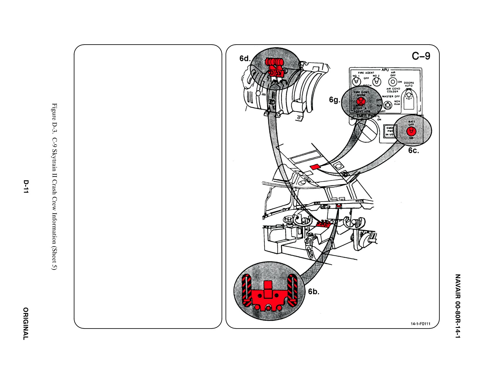
b. ENGINE SHUTOFF T-HANDLES
PULL Engine Fire Shutoff T-Handles,
located on upper portion of instrument
panel.
c. BATTERY SWITCH
PLACE Battery Switch, located below APU
control panel, in OFF position.
d. THROTTLES
RETARD Throttles to FULL AFT position.
e. N/A
f. N/A
g. AUXILIARY POWER UNIT (APU)
PLACE APU Fire Control Switch, located
on overhead switch panel, in OFF and
AGENT ARM position.
7.
BATTERIES
Batteries are located in electrical/electronic
compartment. To further deactivate batteries
remove quick disconnect fitting(s).
a. N/A
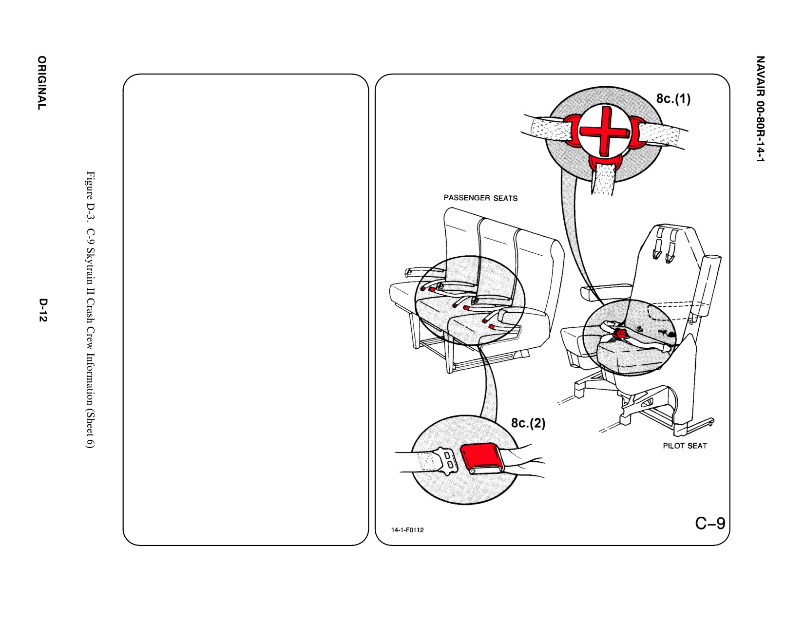
8. CREW RELEASE
Pilot, copilot, and crewchief are attached to
the seats by shoulder harnesses secured to a
lap belt equipped with a quick disconnect
buckle. Passengers have lap belts only.
a. N/A
b. N/A
c. RESTRAINTS SUIT BELTS/RELEASE
(1) ROTATE lap belt quick disconnect
fitting to release shoulder harnesses
and lap belt.
(2) PASSENGER — LIFT buckle cover to
release lap belt (airline type).
d. N/A
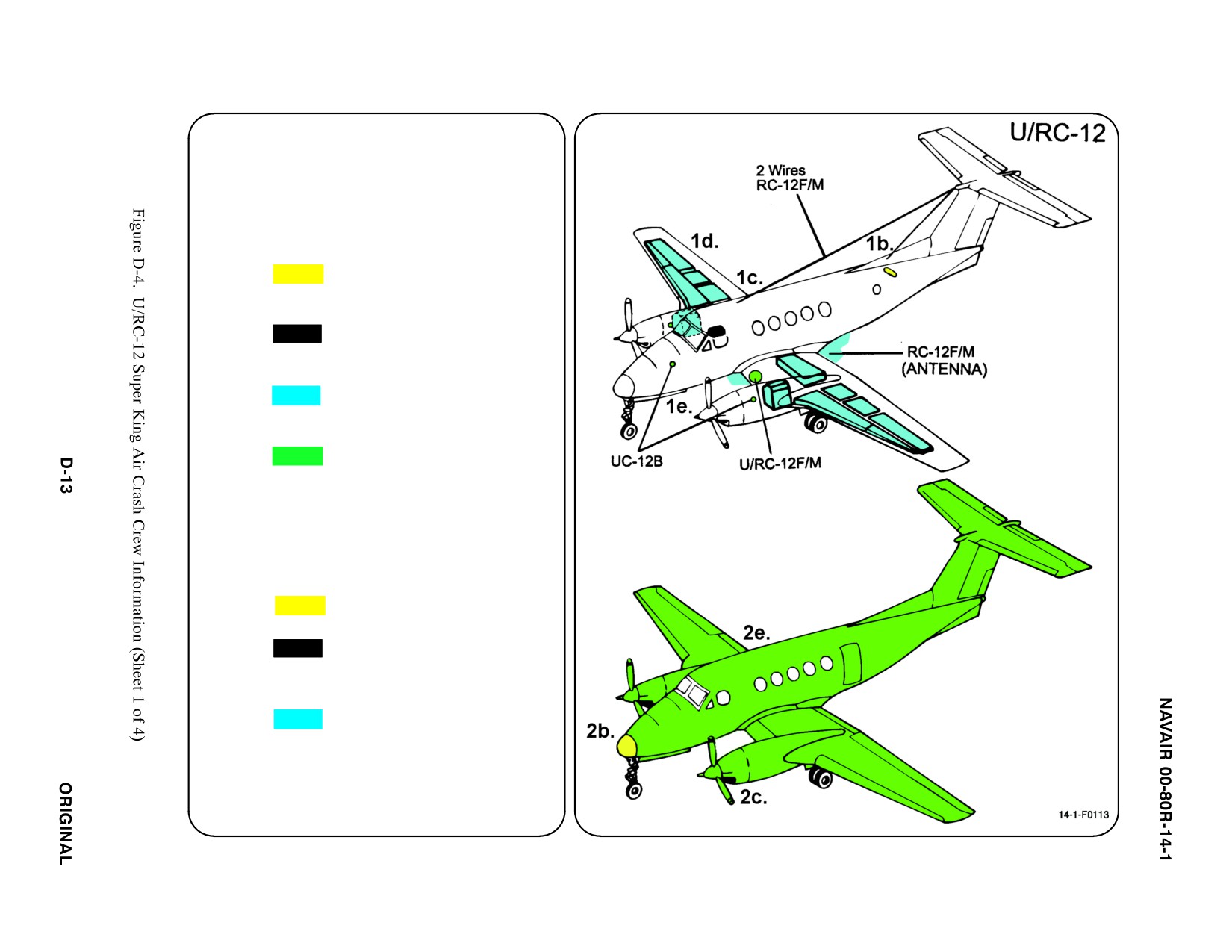
SPECIAL TOOLS/EQUIPMENT
Power Rescue Saw
Crash Axe
1. GENERAL AIRCRAFT INFORMATION
a. N/A
b. Oxygen/LOX
49 ft3
c. Battery
1 (RH Wing Center
ąSection)
d. Fuel
Internal 544 gal
e. Oil
Engine 6 gal
Hydraulic 3.5 gal
1 pt (UC-12B)
f. N/A
2. AIRFRAME MATERIALS
a. N/A
b. Other
ąFiberglass
c. Steel
d. N/A
e. Aluminum
f. N/A
g. N/A
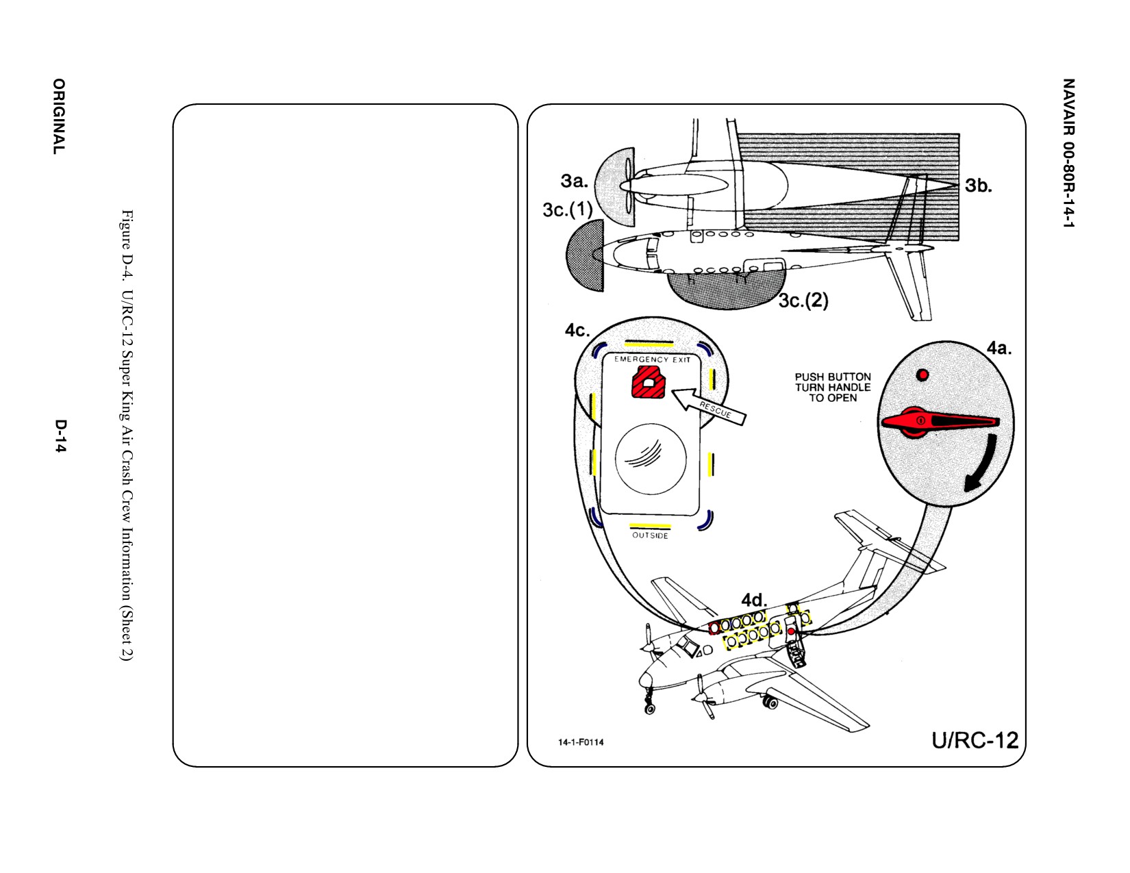
3.
AIRCRAFT DANGER AREAS
a. Propeller Danger Zone — 9i
b. Propeller Turbulence/Engine Exhaust
ąIdle — 18i
ąMax — 40i
c. Radar
(1) Weather — 6i
(2) Reconnaissance (RC-12F/M) — 90i
4.
AIRCRAFT ENTRY
a. NORMAL ENTRY
A swing-down door provides a stairway for
normal entry. The door locking mechanism
is operated by interconnected handles, one
inside and one outside. A button above the
door handle, must be DEPRESSED before
the handle can be ROTATED to open the
door.
b. N/A
c. EMERGENCY ENTRY
A plug-type Emergency Exit Hatch is
located at the first cabin window on the RH
side of the aircraft. When released, the
hatch removes from the frame towards the
inside of the cabin. The hatch is released
from the outside with a flush mounted
Pull-Out Handle.
Note
Hatch may be locked from the inside with key.
d. FORCED ENTRY
CUT OUT entry areas as indicated in
diagram using power rescue saw or crash
axe.
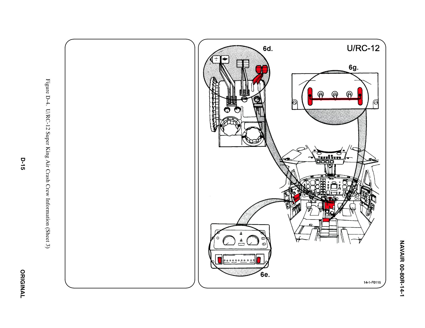
5.
N/A
6.
ENGINE SHUTDOWN
a. N/A
b. N/A
c. N/A
d. CONDITION LEVERS
MOVE Condition Levers, located on center
pedestal, AFT to CUT OFF position.
e. FUEL VALVE SWITCHES
f. N/A
PLACE Fuel Valve Switches in CLOSED
position by RAISING guard and MOVING
switches DOWN.
g. BATTERY SWITCH
PLACE Master Gang Bar in DOWN
position.
7.
BATTERY
The battery is located in the right wing center
section beneath an access cover secured with
screws and is equipped with a quick
disconnect fitting.
a. N/A
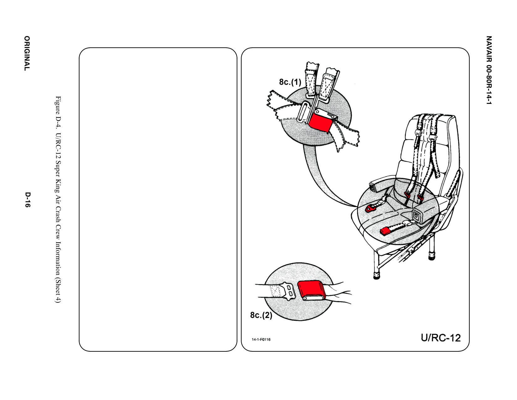
8. CREW RELEASE
The pilot and copilot are attached to the seats
by a shoulder harness attached to a lap belt
by a quick disconnect buckle. The passengers
have lap belts only.
a. N/A
b. N/A
c. RESTRAINTS SUIT BELTS/RELEASE
(1) LIFT buckle cover to release lap belt
and shoulder harness.
(2) PASSENGER — LIFT buckle cover to
release lap belt (airline type).
d. N/A
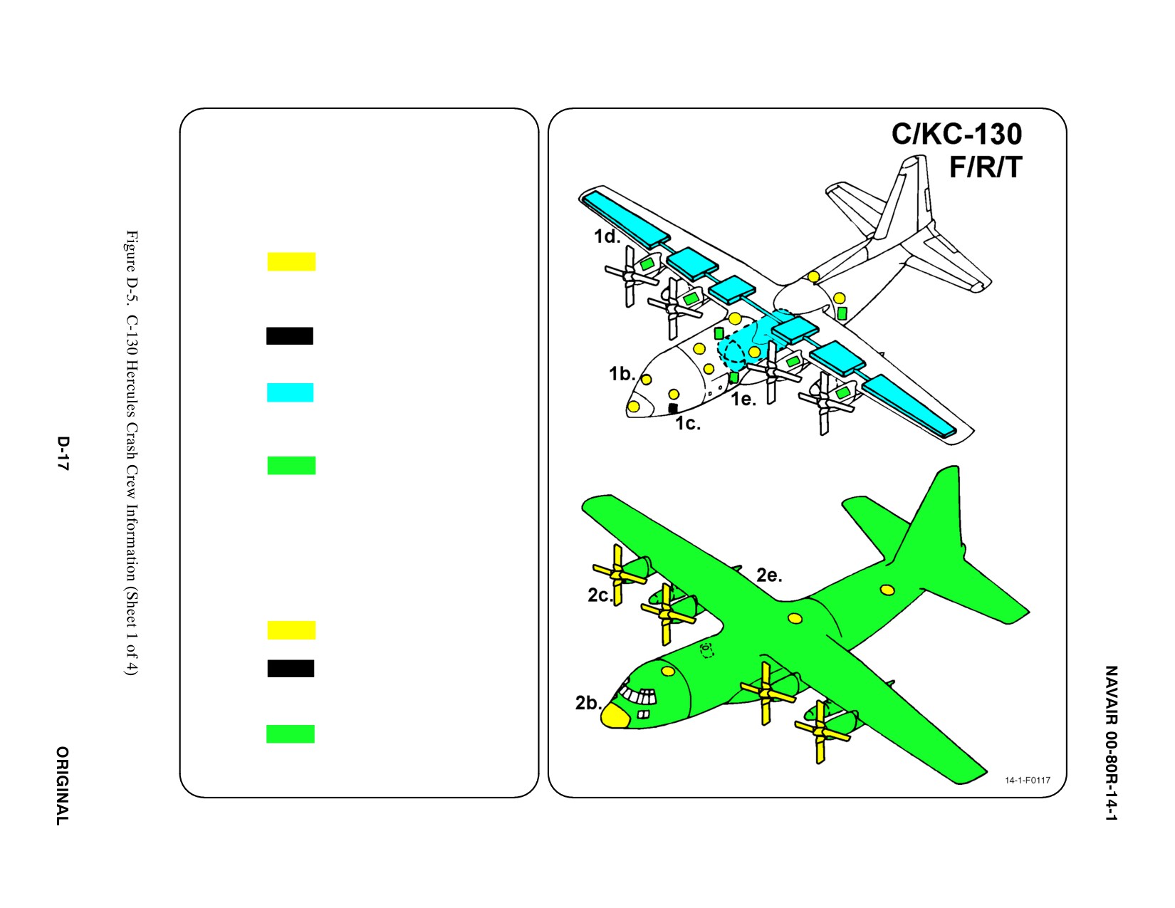
SPECIAL TOOLS/EQUIPMENT
Power Rescue Saw
Crash Axe
1. GENERAL AIRCRAFT INFORMATION
a. N/A
b. Oxygen/LOX
25 L Fixed
4 Portable Bottles
LOX ON
ąC/KC-130T/J only
c. Battery
2
d. Fuel
Cargo Aircraft
ą9,800 gal
Refueling Aircraft
ą10,224 gal
e. Oil
Engine 48 gal
Hydraulic 29.59 gal
f. Pneumatic
3000 PSI
ąSystem
2.
AIRFRAME MATERIALS
a. N/A
b. Other
ąFiberglass
c. Steel
d. N/A
e. Aluminum
f. N/A
g. N/A
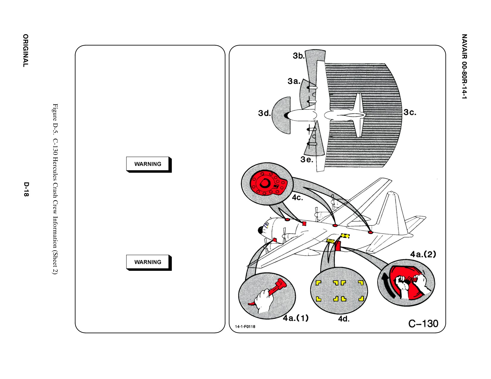
3. AIRCRAFT DANGER AREAS
a. Propeller Danger Zone — 10i
b. Turbine Blade Failure — 300i
c. Propeller Blast — 300i
d. Radiation — 37i
e. GTC Exhaust Area
4. AIRCRAFT ENTRY
a. NORMAL ENTRY
(1) ROTATE Crew Door Handle
DOWNWARD. Allow door to swing
down slowly.
Stand clear of door when operating handle to
prevent injury should door fall free.
(2) ROTATE Paratroop Jump Door Handle
CLOCKWISE, PUSH IN and SLIDE
door UPWARD.
b. N/A
c. EMERGENCY ENTRY
PULL Emergency Release Ring on hatch or
door and PUSH INWARD.
Emergency exit door (right side of fuselage) will
fall into aircraft upon release. Clear personnel
before door is released.
d. FORCED ENTRY
CUT OUT entry areas as indicated on
diagram using power rescue saw or crash
axe.
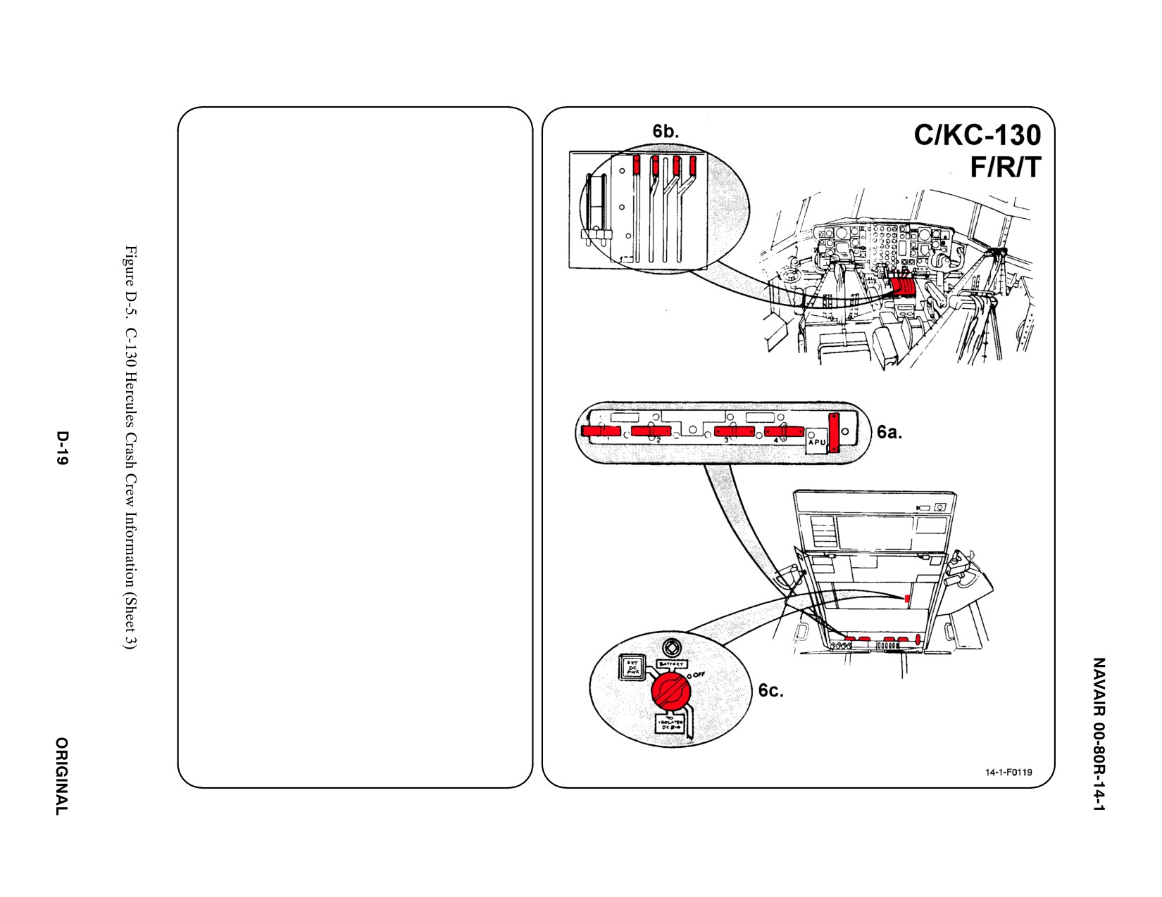
5.
N/A
6.
ENGINE SHUTDOWN
a. FIRE HANDLES
PULL OUT all five Fire Handles.
b. CONDITION LEVERS
PULL all four levers BACK to the FULL AFT
position.
c. BATTERY SWITCH
PLACE Battery Switch in OFF position.
d. N/A
e. N/A
f. N/A
g. N/A
7.
BATTERY
Two batteries are located in fuselage
compartment FWD of crew door on LH side of
aircraft. Disconnect, time permitting.
a. N/A
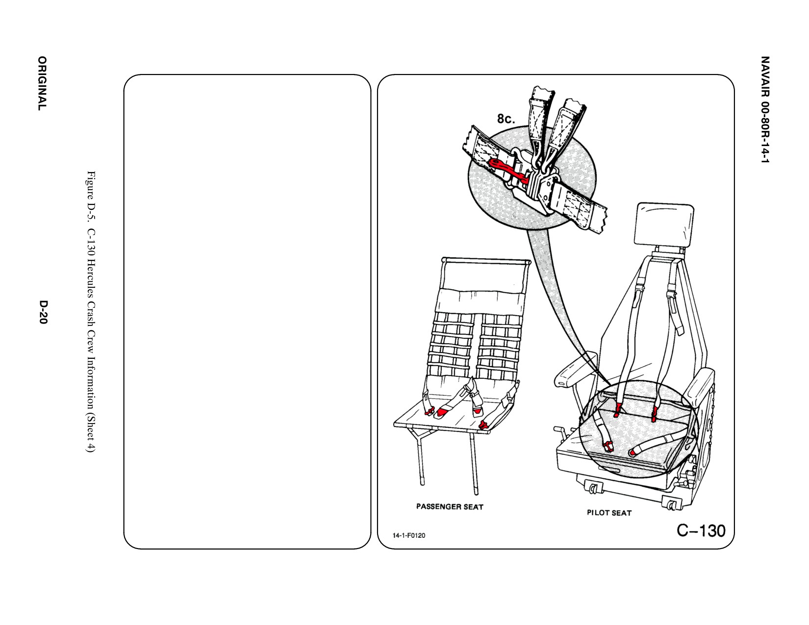
8. CREW RELEASE
All crewmembers are attached to the seats by
shoulder harnesses secured to lap belts with
quick disconnects. Passengers have lap belts
only.
a. N/A
b. N/A
c. RESTRAINTS SUIT BELTS/RELEASE
LIFT quick disconnect lever to release
shoulder harnesses and lap belt.
d. N/A
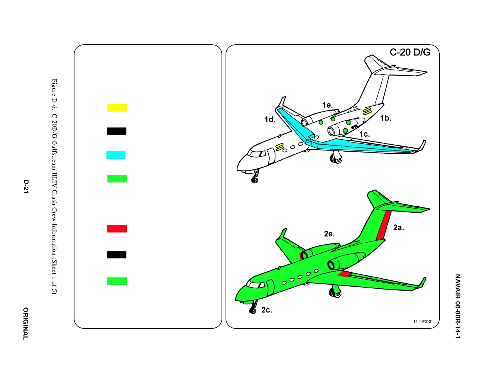
SPECIAL TOOLS/EQUIPMENT
Power Rescue Saw
Crash Axe
1. GENERAL AIRCRAFT INFORMATION
a. N/A
b. Oxygen
Two 77 ft3 and
Two 115 ft3 Bottles
c. Battery
2
d. Fuel
Internal 4134 gal
e. Oil
Engine 3.8 gal
Hydraulic 6.7 gal
f. Pneumatic
3,000 PSI
ąSystem
2. AIRFRAME MATERIALS
a. Graphite Epoxy
b. N/A
c. Steel
d. N/A
e. Aluminum
f. N/A
g. N/A
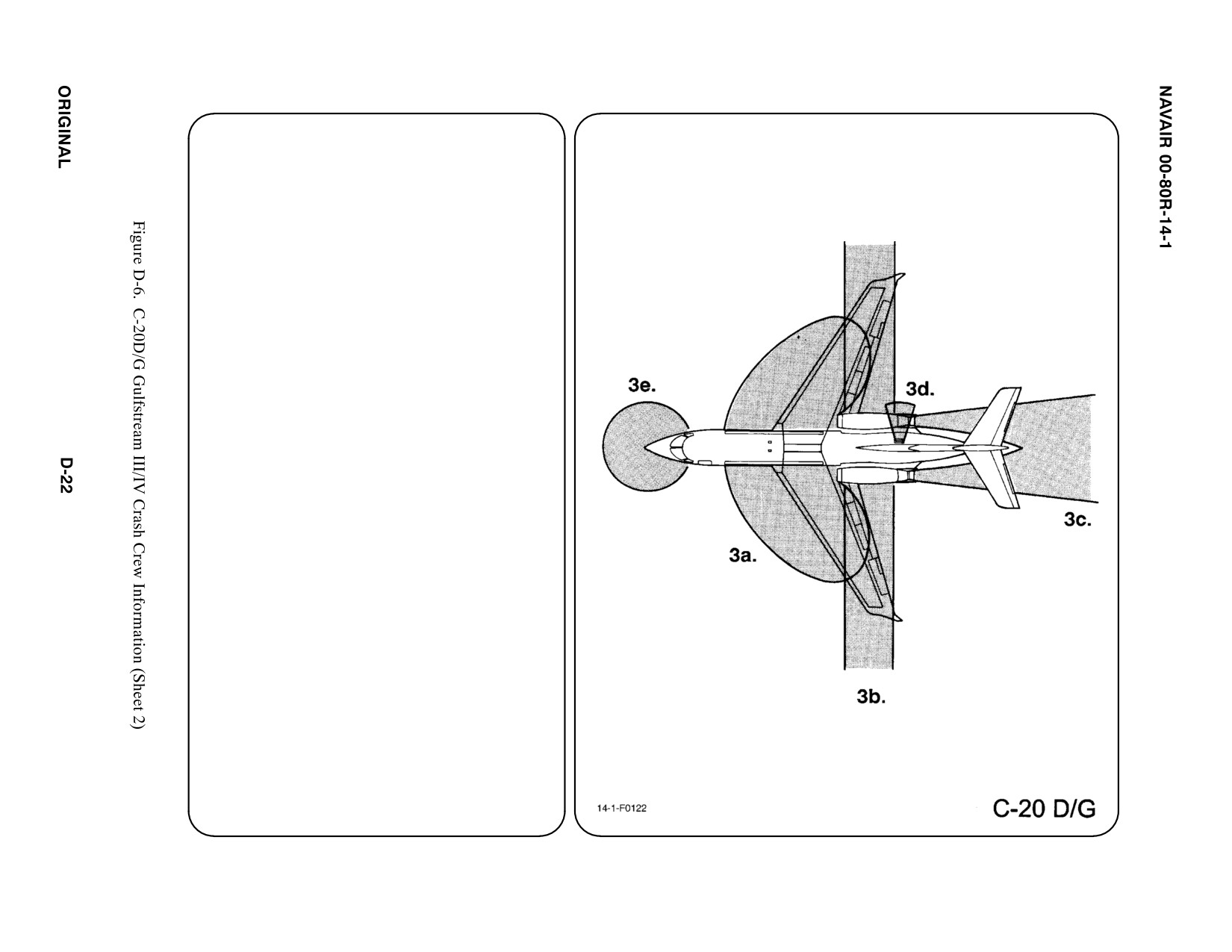
3. AIRCRAFT DANGER AREAS
a. Inlet Suction — 20i
b. Turbine Blade Failure — 300i
c. Engine Exhaust — 250i
d. APU Exhaust — 5i
e. Radiation FWD 270_ Arc — 15i
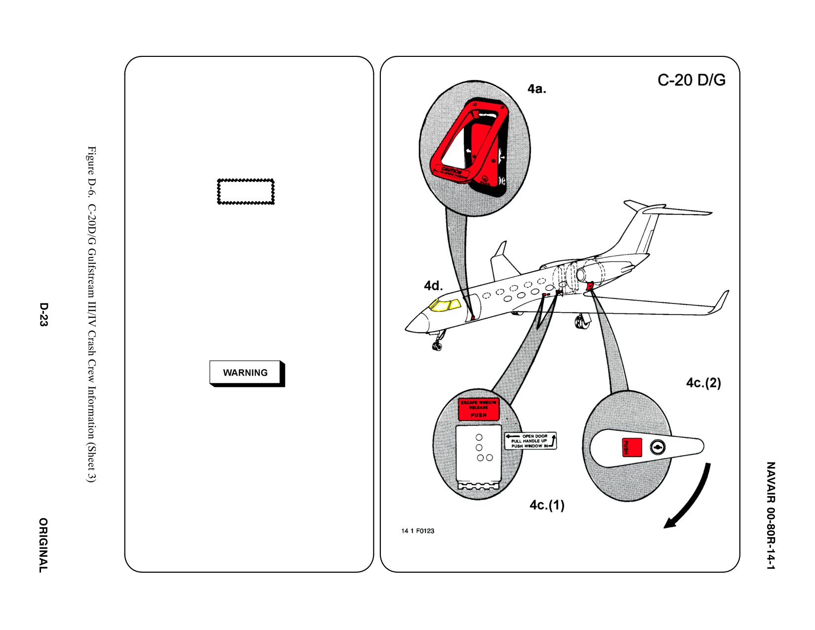
4. AIRCRAFT ENTRY
a. NORMAL ENTRY
Normal entry to the aircraft is through the
main entrance door. The swing-down door
provides a stairway for entry. PUSH the
small Inner Panel to release Secondary
Lock. PULL the larger Outer Handle (on the
bottom) OUT to release the Primary Lock.
The door will freefall to OPEN
CAUTION
Door will fall rapidly. Support door while lowering.
b. N/A
c. EMERGENCY ENTRY
In the event the main entrance door is
inaccessible, entry may be gained by using
the emergency escape windows or the
baggage compartment door.
(1) PUSH the Emergency Escape Window
panel where indicated. Open Door, PULL
Handle UPWARD, and PUSH window
INWARD.
Emergency exit door (starboard side of fuselage)
will fall into aircraft upon release. Personnel
inside of aircraft should stand clear of door before
door is released.
(2) PUSH Button in center of Baggage
Compartment Door Handle. ROTATE
Handle CLOCKWISE, PUSH Door
INWARD and SLIDE UPWARD. Once
inside Baggage Compartment, OPEN
Door to Lavatory, then OPEN Door to
Cabin. 123
4. AIRCRAFT ENTRY (CONT.)abc
d. FORCED ENTRY
Glass fragments created when chopping or
cutting windshields in the cockpit area may
cause severe injuries to those in the cockpit.
CUT OUT entry areas as required using power
rescue saw or crash axe.
5.
N/A
6.
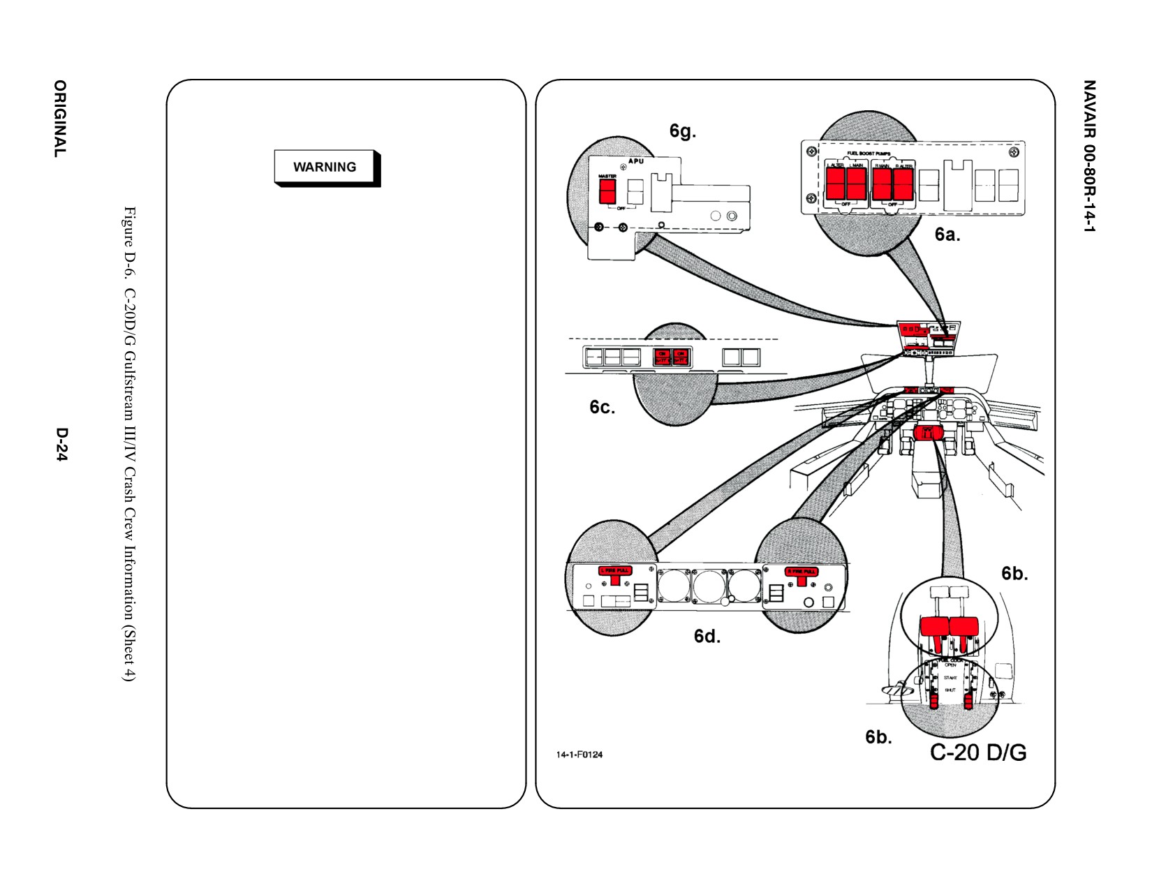
ENGINE/APU SHUTDOWN
a. FUEL BOOST PUMP SWITCHES
LIFT both clear Guards and PLACE all four Fuel
Boost Pump Switches DOWN in OFF position.
b. FUEL COCK LEVERS
PULL both Fuel Cock Levers FULLY AFT to
SHUT position.
c. BATTERY SWITCHES
PUSH both BATT 1 and BATT 2 Buttons to
release each from depressed position (“ON” light
should go out).
d. FIRE T-HANDLES
PULL both Fire T-Handles.
e. N/A
f. N/A
g. APU MASTER SWITCH
PLACE APU Master Switch in DOWN (OFF)
position.
7.
BATTERIES
Batteries are located in the Battery Compartment in
the LH tail section of the aircraft. To further
deactivate batteries, REMOVE Quick Disconnect
Fittings, time permitting.
a. N/A
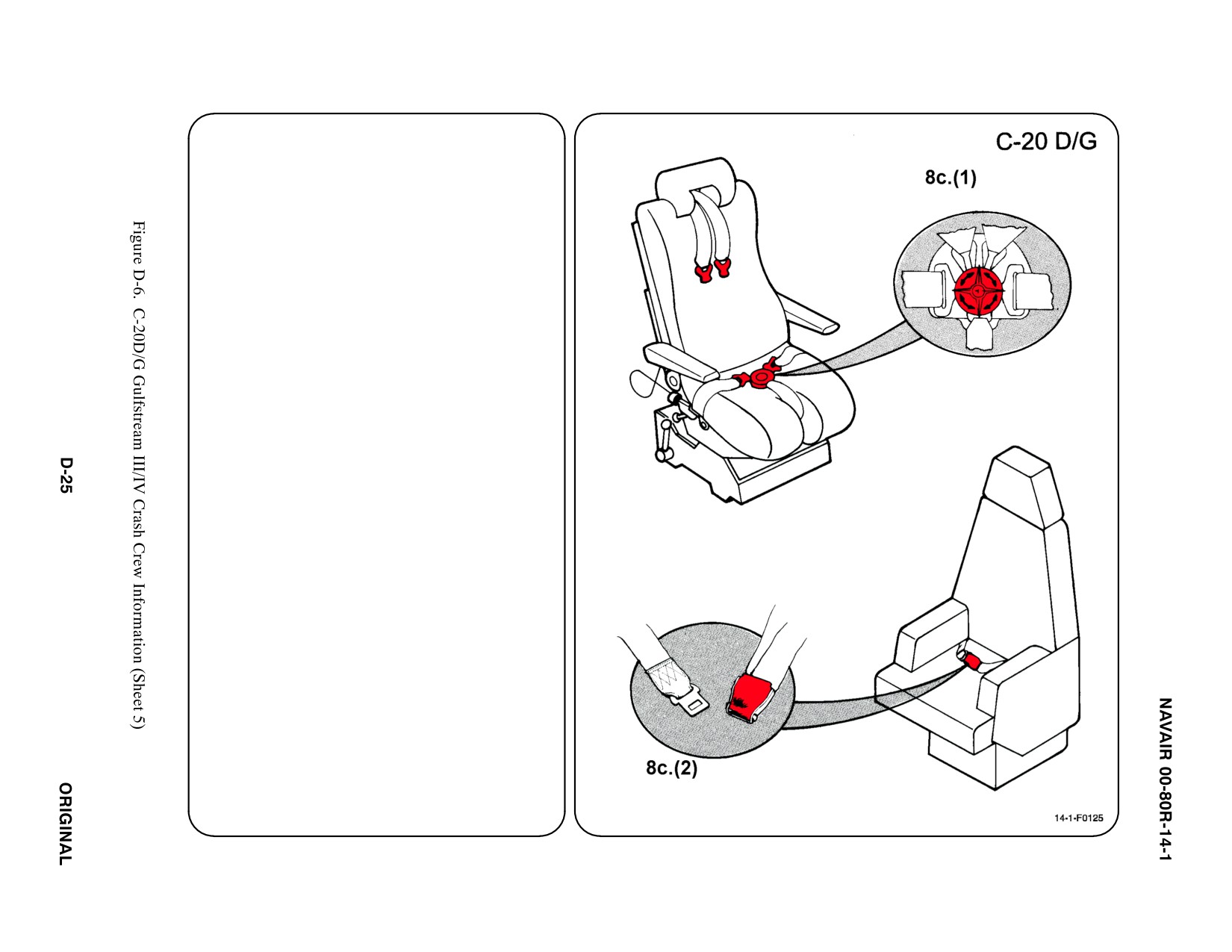
8. CREW RELEASE
The pilot and copilot seats are equipped with
shoulder harness straps, lap belts, and crotch
straps attached to a rotary release buckle.
The passenger seats have lap belts only.
a. N/A
b. N/A
c. RESTRAINTS SUIT BELTS/RELEASE
(1) ROTATE Rotary Release Buckle in
EITHER DIRECTION to release
Shoulder Harness, Lap Belt and Crotch
Strap.
(2) PASSENGER — LIFT Buckle Cover to
release Lap Belt (airline type).
d. N/A
SPECIAL TOOLS/EQUIPMENT
Power Rescue Saw
6-Foot Ladder
1. GENERAL AIRCRAFT INFORMATION
a. N/A
b. Oxygen/LOX
49 ft3
c. Battery
2 (1 port, 1 starboard)
d. Fuel
Internal 648 gal
e. Oil
Engine 8 gal
Hydraulic 8 gal
f. N/A
g. N/A
2. AIRFRAME MATERIALS
a. N/A
b. Other
ąAcrylic
c. Steel
d. N/A
e. Aluminum
f. N/A
g. N/A
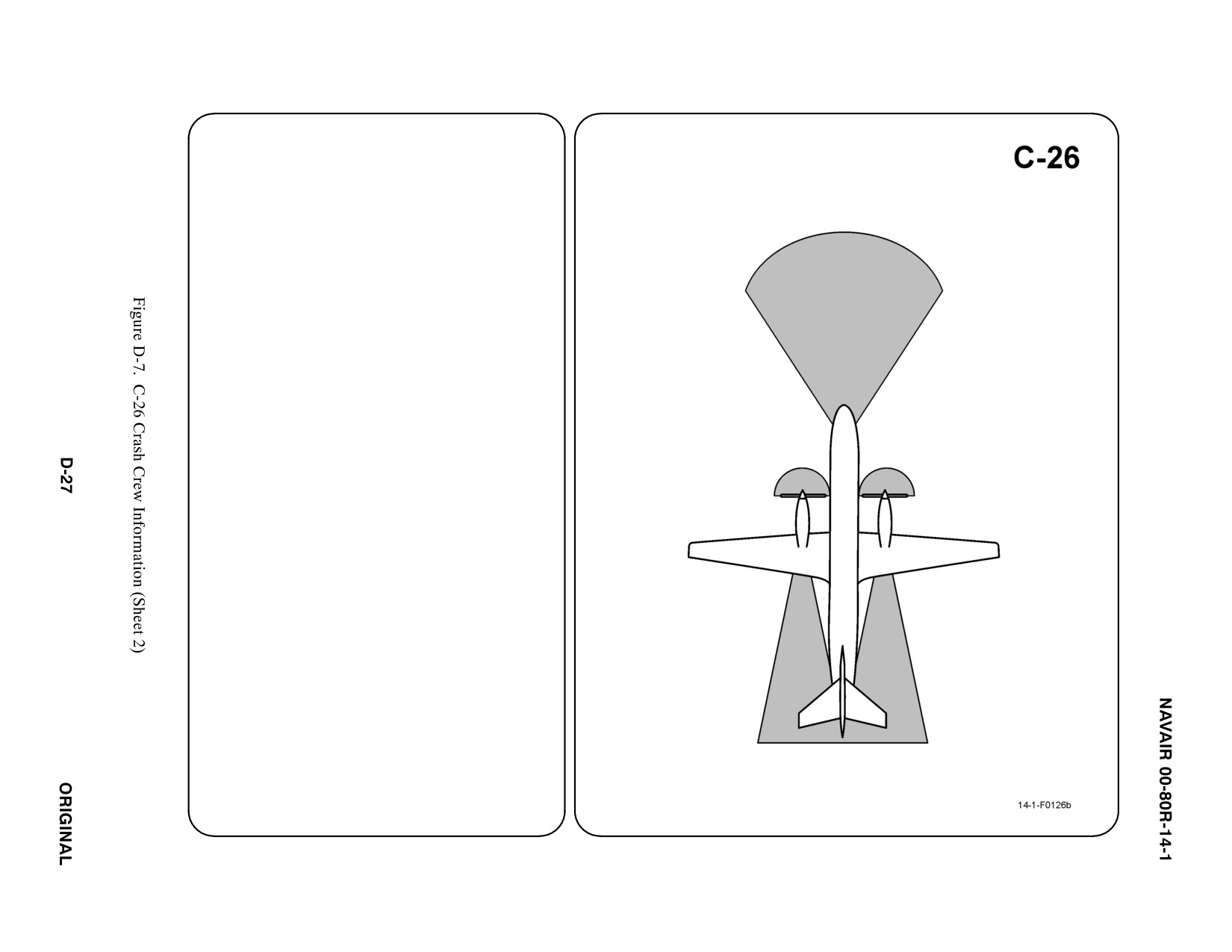
3. AIRCRAFT DANGER AREAS
a. Propeller Danger Zone — 9i
b. Propeller Turbulence/Engine Exhaust
ąIdle — 18i
ąMax — 40i
c. Radar — 6i
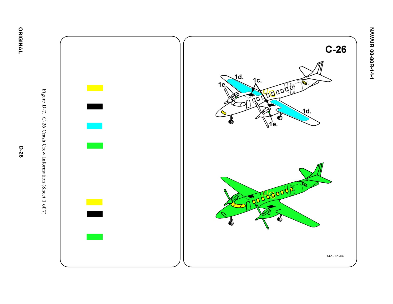
3c.
3a.
3a.
3b.
3. AIRCRAFT DANGER AREAS (CONT.)
Note
The C-26 is a joint service aircraft used by the
USAF, US Army, US Navy, and State
Department for drug interdiction.
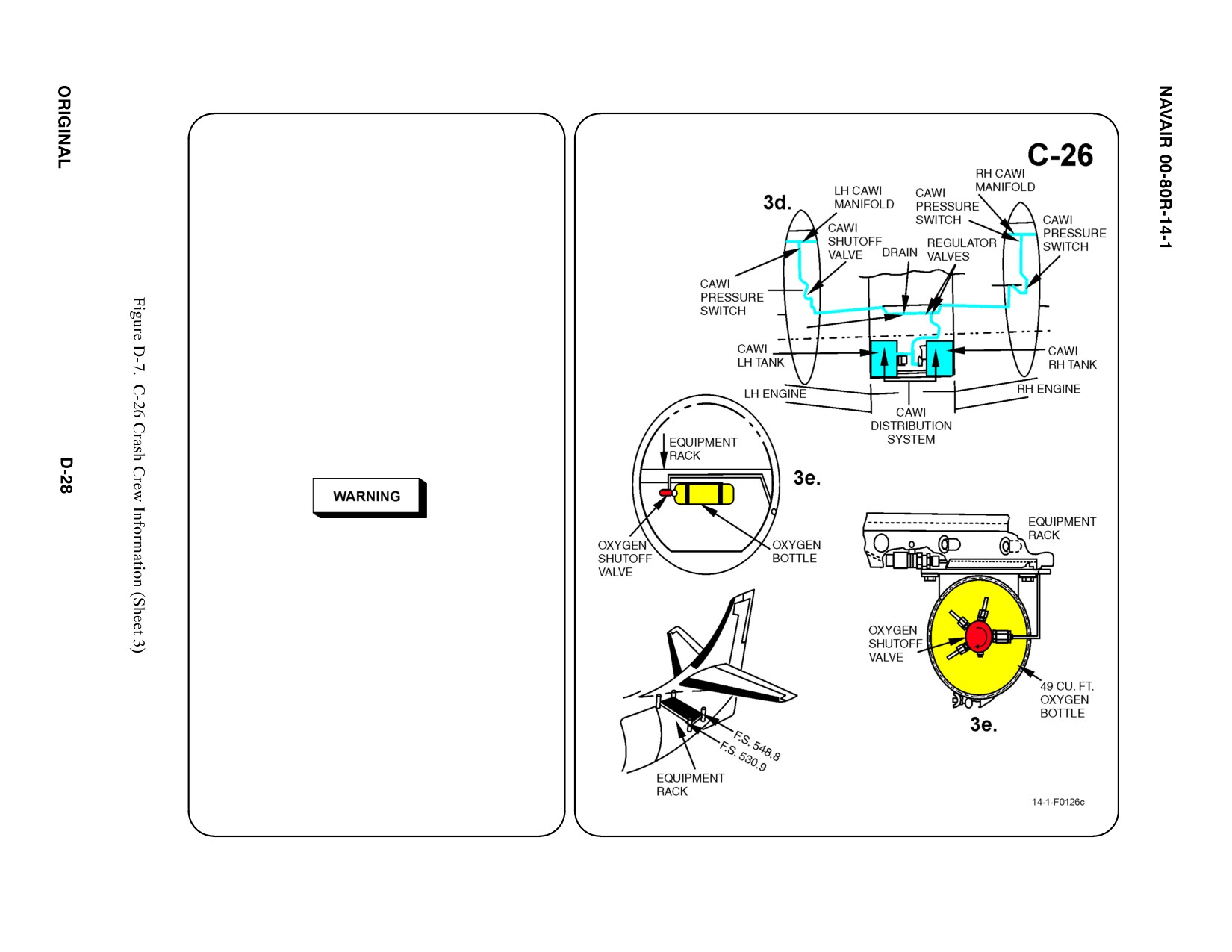
d. ALCOHOL-WATER (AWI) FLUID
MIXTURE
The C-26 (SA 227-DC model) uses an
alcohol-water mixture composition (CAWI
system) with a quantity of 14 US gallons or
54 liters. The mixture is Methyl Alcohol 40%
and water 60%. Prior to flight the CAWI
tank will be full. The interconnected storage
tanks are located between the fuselage
lower skin and the wing belly panel.
Common plumbing is routed through each
wing leading edge to each engine.
Methyl Alcohol (Methanol) is a violent poison
and can not be made nonpoisonous. In case of
accidental contact, flush with water immediately.
Methanol vapors are toxic and extremely
flammable. Do not smoke, generate sparks, or
expose Methanol to open flame.
e. OXYGEN BOTTLE AND SHUTOFF
VALVE LOCATION
The C-26 (SA 227-DC) contains one
oxygen bottle located beneath the
equipment rack aft of the aft cargo
compartment bulkhead. Oxygen lines are
routed to the pilot and co-pilot and along the
right side of the fuselage to the passengers.
A shut-off valve is located on each
regulator.
4.
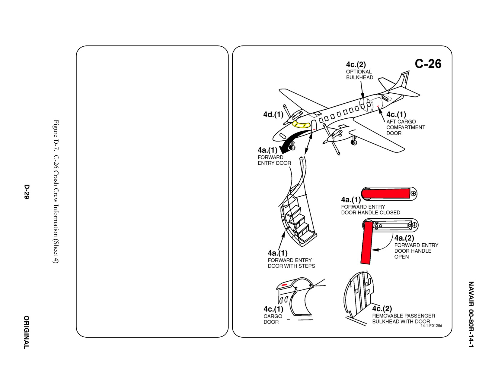
AIRCRAFT ENTRY — SA226/227 MODELS
a.
NORMAL ENTRY
(1) Push in on forward end of entry door
handle. Door is located on forward left
side of aircraft.
(2) Rotate entry door handle down,
clockwise, to open.
(3) Pull out on door handle. (Door is
hinged at the bottom and will rotate out
from the top).
b. N/A
c.
EMERGENCY ENTRY
(1) The cargo door handle operates same
as the forward entry door handle.
Cargo door must be lifted up to open.
Cargo door is located on aft left side of
aircraft.
(2) Optional bulkhead separates
passenger compartment and cargo
compartment. The bulkhead may be
removable and may contain a door.
Can also be used as an emergency
entry and exit.
d. FORCED ENTRY
(1) Cut along window lines. There are no
cut-in marks painted on the aircraft.
The area 14 inches above and 3 inches
below the window will offer the least
resistance for forced entry.
5.
N/A
6.
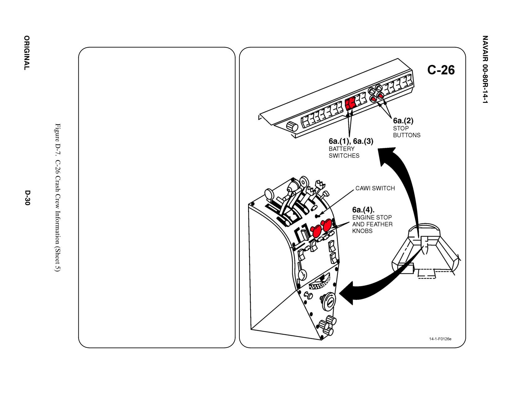
ENGINE SHUTDOWN
a.
ENGINE SHUTDOWN
(1) Ensure at least one battery switch is
ON (forward position). Battery switches
are located straight forward of pilot's
control column.
(2) Push stop buttons, located below left
instrument panel. (Approx. 5 inches to
right of battery switches.)
(3) Place both battery switches to OFF
(center) position.
(4) Pull both engine stop and feather
knobs, located on center pedestal just
below engine controls, full aft. Controls
are red.
b. N/A
c.
N/A
d. N/A
e.
N/A
f.
N/A
g. N/A
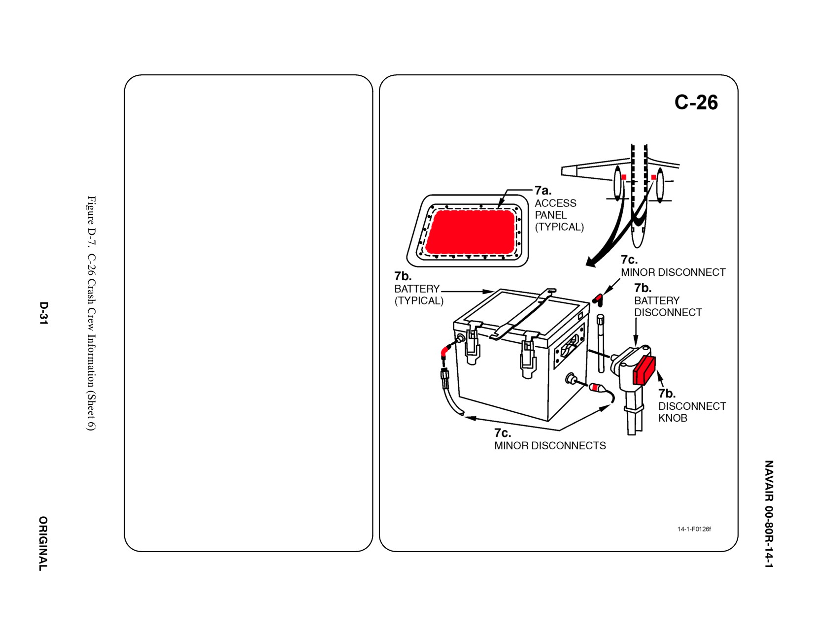
7. BATTERY
Note
Aircraft is equipped with two 24 volt 23 Ah Ni/Cd
batteries.
a. Remove battery access panels from upper
surface of left and right inboard wing.
b. Disconnect main battery quick disconnect
by turning battery disconnect knob
counterclockwise.
c. Disconnect minor battery quick
disconnects by turning connectors
counterclockwise.
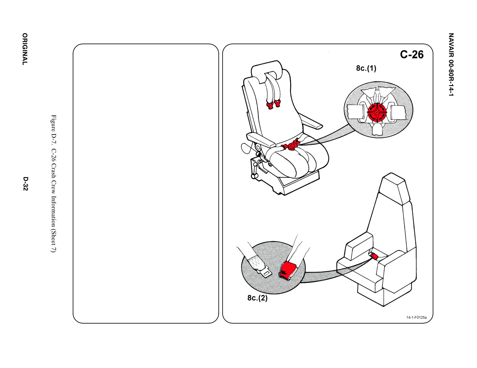
8. CREW RELEASE
The pilot and copilot seats are equipped with
shoulder harness straps, lap belts, and crotch
straps attached to a rotary release buckle.
The passenger seats have lap belts only.
a. N/A
b. N/A
c. RESTRAINTS SUIT BELTS/RELEASE
(1) ROTATE Rotary Release Buckle in
EITHER DIRECTION to release
Shoulder Harness, Lap Belt and Crotch
Strap.
(2) PASSENGER — LIFT Buckle Cover to
release Lap Belt (airline type).
d. N/A
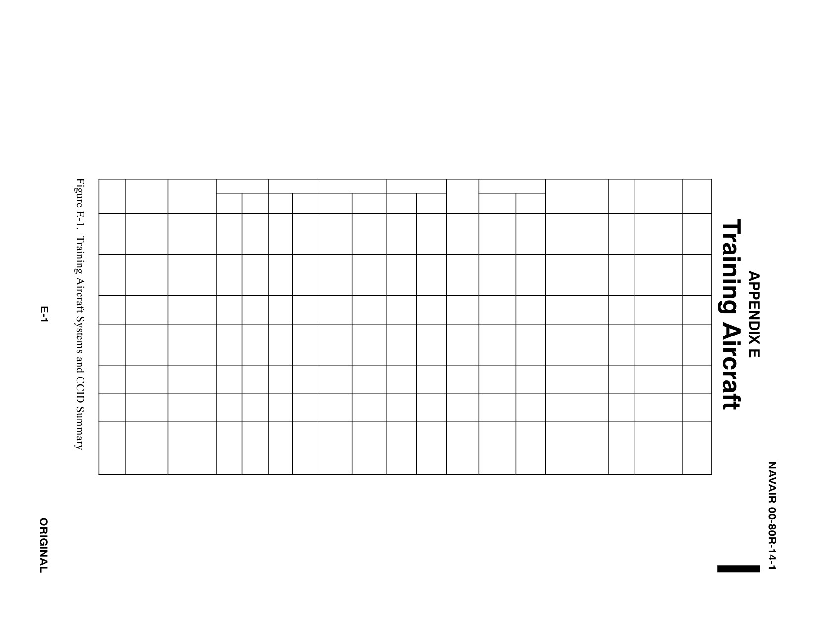
TRAINING AIRCRAFT SYSTEMS AND
CRASH CREW INFORMATION DIAGRAMS SUMMARY
FUEL (GAL)
OIL (GAL)
OXYGEN
PNEU SYS
ORDNANCE
AIRFRAME
FWD
FREE
TYPE
NAME
MATERIALS
INT
EXT
ENG
HYD
LOX
BOTTLE
GAS
AIR
GUN
FIRE
FALL
PYROTECHNICS
BTRY
EJECT SYS
S.O.B.
PYLON EJECTOR
ALUMINUM
SEAT
CARTRIDGES (2)
3200
50 CAL
MISSILES
NORTH AMER
T-2
BUCKEYE
STEEL
487
204
2
1
10L
PAN
NONE
BOMBS
STA.
2
2
PSI*
POD
ROCKETS
LS-1A
FIBERGLASS
(2)
CANOPY
EJECTION SEATS
T-6
TEXAN II
ALUMINUM
165
NONE
18.5
5
OBOGS
SEAT
NONE
NONE
NONE
PYLON EJECTOR
2
MKUS16LA
2
STEEL
QTS
QTS
PAN
CARTRIDGES (2)
EJECTION
FIBERGLASS
(2)
STA.
SEAT
CANOPY
EJECTION SEATS
ALUMINUM
N2
TURBO
T-34C
STEEL
130
NONE
4.4
1 PT
NONE
NONE
3000
NONE
NONE
NONE
NONE
NONE
1
NONE
2
MENTOR
FIBERGLASS
PSI
T-38
TALON
ALUMINUM
598
275
2
3.5
5L
NONE
NONE
3000
NONE
NONE
NONE
PYLON EJECTOR
1
NORTHROP
2
STEEL
PSI
CARTRIDGES (2)
M38
MAGNESIUM
STA.
FIBERGLASS
CANOPY
EJECTION SEATS
ALUMINUM
77.9FT3
N2
D8
SABRE-
T-39
STEEL
1087
NONE
4.0
2.0
NONE
(2)
3000
NONE
NONE
NONE
NONE
NONE
2
NONE
G9
LINER
FIBERGLASS
11FT3
PSI
N6
ALUMINUM
T-44
KING AIR
STEEL
388
NONE
2.3
1 PT
NONE
49 FT3
NONE
NONE
NONE
NONE
NONE
NONE
1
NONE
7
FIBERGLASS
ALUMINUM
STEEL
PYLON EJECTOR
ACRYLIC
SEAT
N2
CARTRIDGES (2)
MB
PRAC
T-45A
GOSHAWK
TITANIUM
432
0
3.7
4.3
OBOGS
PAN
1300
0
NONE
ROCKETS
STA
2
SJU-17(V)
2
BOMBS
FIBERGLASS
(2)
PSI
CANOPY
SERIES
CARBON
EJECTION SEATS
COMPOSITES
*Canopy Emergency Jettison
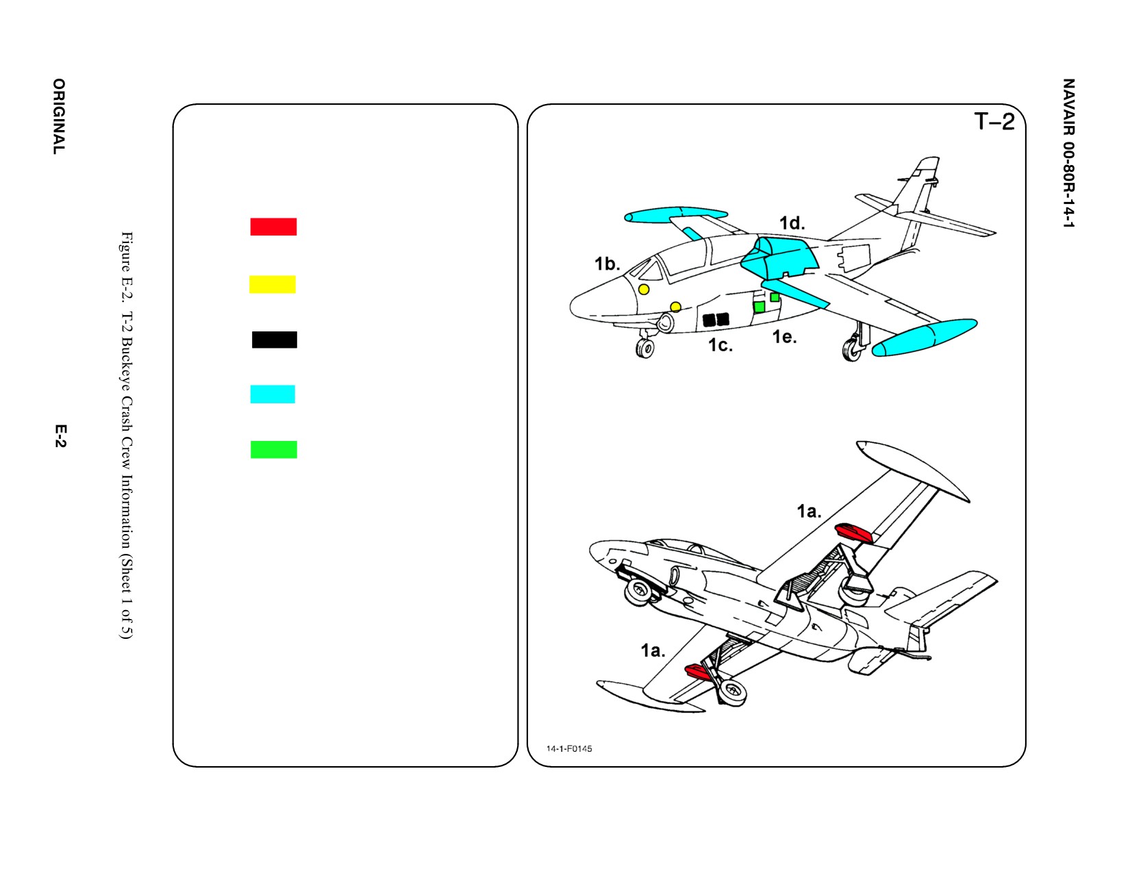
SPECIALS TOOLS/EQUIPMENT
Power Rescue Saw
Crash Axe
1. GENERAL AIRCRAFT INFORMATION
a. Armament
2 Wing Stations
b. Oxygen/LOX
10 L
c. Battery
2
d. Fuel
Internal 487 gal
External 204 gal
e. Oil
Reservoir for
each engine: 1.0 gal
Hydraulic 1.1 gal
f. N/A
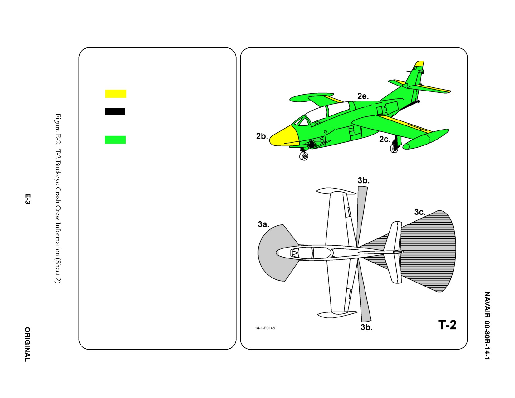
2. AIRFRAME MATERIALS
a. N/A
b. Other
Fiberglass
c. Steel
d. N/A
e. Aluminum
f. N/A
g. N/A
3. AIRCRAFT DANGER AREAS
a. Inlet Suction — 15i
b. Turbine Blade Failure — 300i
c. Engine Exhaust — 300i
ąIdle — 40i
ąMax — 65i
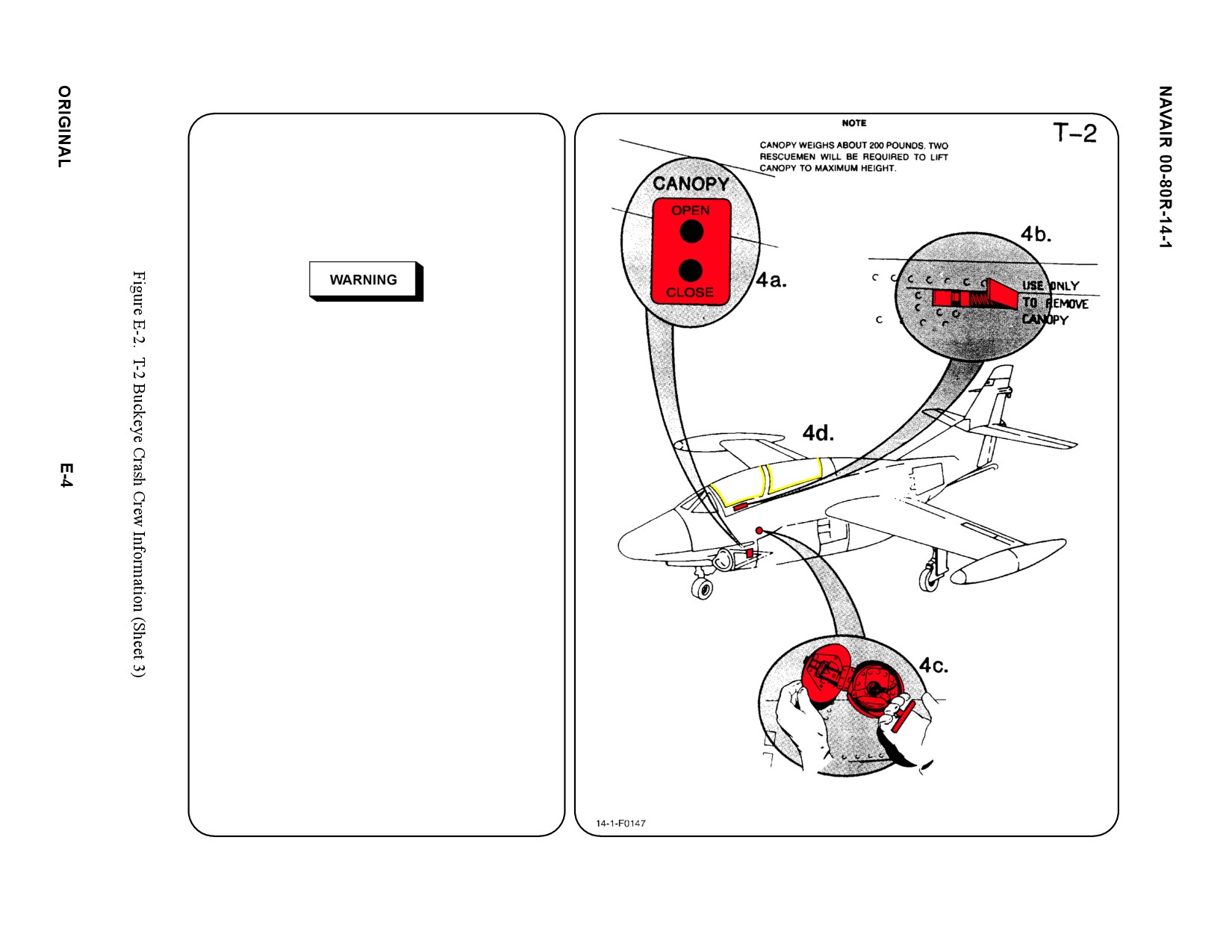
4. AIRCRAFT ENTRY
a. NORMAL ENTRY
An External Electrical Canopy Switch,
located on the LH side of the fuselage,
opens the canopy vertically to full open
position in 7 seconds.
Do not actuate this switch for emergency
entrance to cockpit. Use of electrical power can
ignite fuel or other flammable material in
damaged aircraft.
b. MANUAL ENTRY
PUSH button and PULL LH External
Canopy Manual Release Handle FULL OUT
(90_). PULL canopy AFT about 1 inch to
release internal latches.
MANUALLY RAISE canopy until canopy
falls OFF to either side.
c. EMERGENCY ENTRY
PULL External Canopy Jettison Handle.
Handle is located in circular panel on
LH side of fuselage.
d. FORCED ENTRY
Canopy is made of acrylic plastic and may
be cut with power rescue saw or crash axe.
CUT along canopy frame.
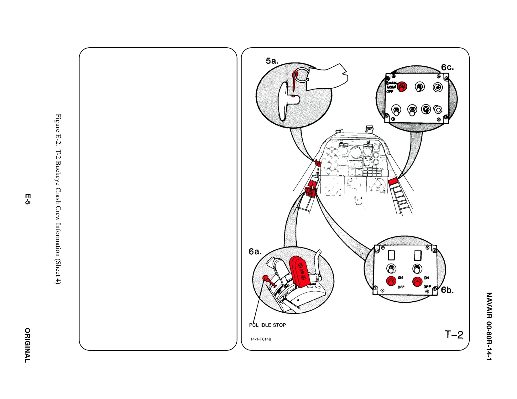
5.
CANOPY SAFETY
a. To prevent accidental discharge of
pneumatic canopy remover tube, INSTALL
safety pins in the Canopy Release Handle
located in the FWD LH corner of each
cockpit.
b. N/A
6.
ENGINE SHUTDOWN
Shut down engine from the FWD cockpit.
a. POWER CONTROL LEVERS
DEPRESS PCL Idle Stop Button if installed.
PULL Power Control Levers AFT and
AROUND DETENT to FULL CLOSED
position.
b. ENGINE MASTER SWITCHES
PLACE No. 1 and No. 2 Engine Master
Switches. in OFF position.
c. BATTERY SWITCH
PLACE Battery Switch in NORM position.
d. N/A
e. N/A
f. N/A
g. N/A
7.
BATTERIES
Batteries are accessible through access door
located FWD LH side of fuselage below the
canopy. Batteries are equipped with quick
disconnect plugs.
a. N/A
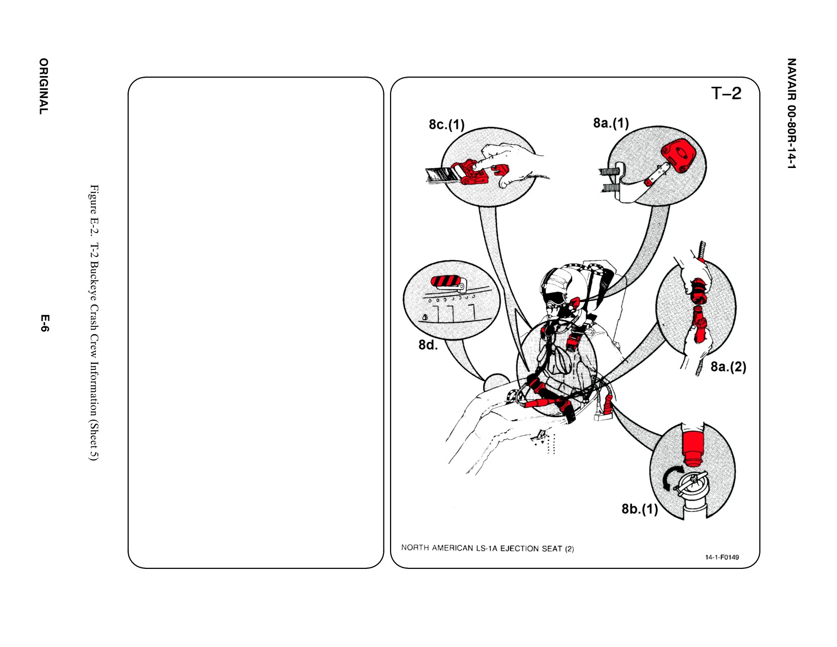
8.
CREW RELEASE
The crewmembers are attached to the seat by
the use of an integrated harness. Additionally,
the oxygen/communication lead is attached to
the survival kit. If crewmembers are warning
anti-G suit a hose will be attached to the LH
side of the seat.
a.
PERSONNEL SERVICE, QUICK
DISCONNECT
(1) Remove oxygen mask by pulling down
on the release tabs on either side of
mask.
(2) To disconnect oxygen/communication
lead, pull up round collar and pull apart
connection.
b. RESTRAINT SUIT BELTS/RELEASE
(1) PULL anti-G suit hose from LH seat
fitting.
c.
HARNESS STRAPS/LEG RESTRAINT
RELEASE
(1) Release two lap belt, then two shoulder
harness koch fittings.
d. EMERGENCY RELEASE
(1) Actuating the Emergency Release
Handle will free the crewmember from
seat. However, the parachute and
survival kit will remain attached to the
crewmember.
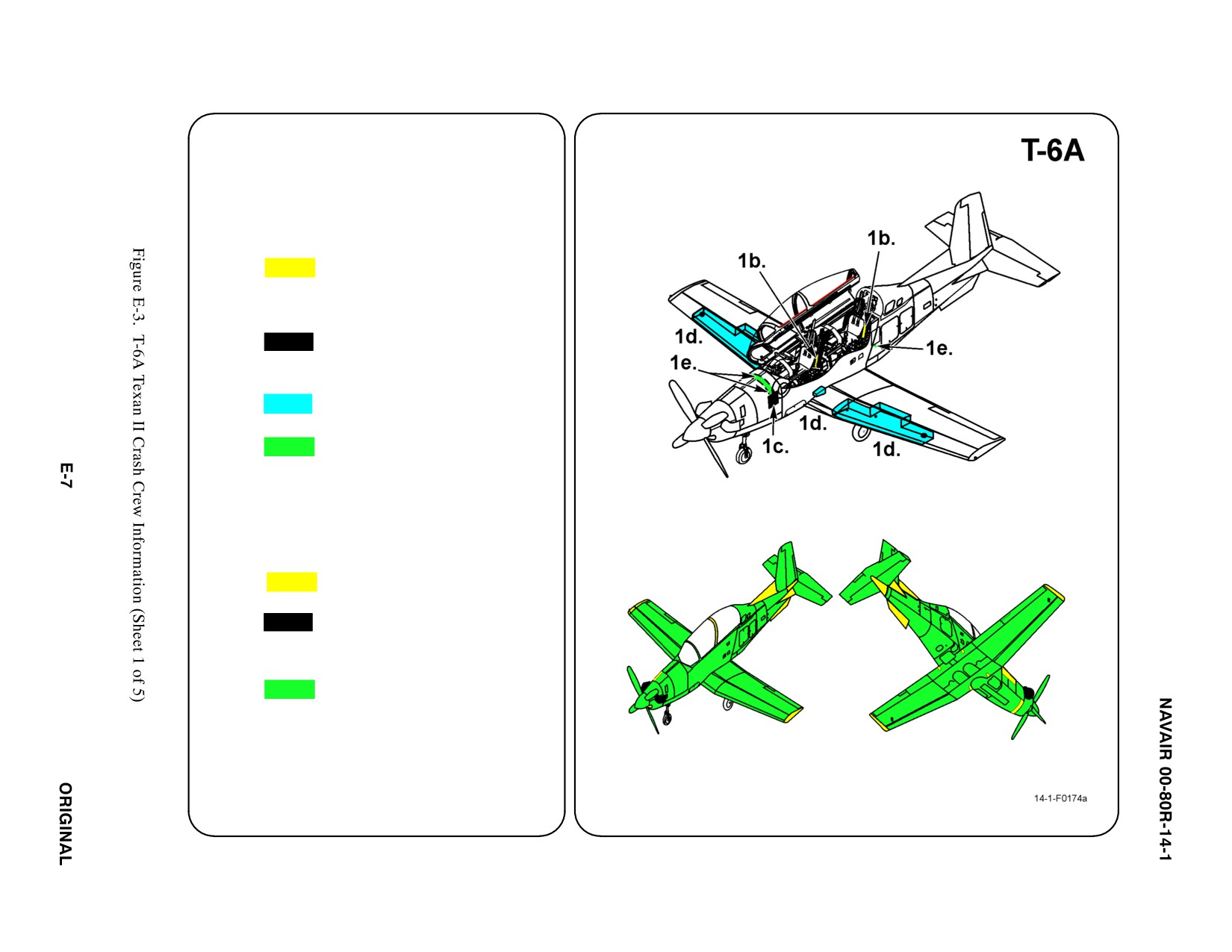
SPECIALS TOOLS/EQUIPMENT
Power Rescue Saw
Crash Axe
1. GENERAL AIRCRAFT INFORMATION
a. N/A
b. Oxygen Bottle
OBOGS
Bailout Bottle (2)
(1 in each seat pan)
c. Battery
2
d. Fuel
Internal 165 gal
e. Oil
Engine 18.5 quarts
Hydraulic 5 quarts
f. N/A
2. AIRFRAME MATERIALS
a. N/A
b. Other:
ąFiberglass
c. Steel
d. N/A
e. Aluminum
f. N/A
g. N/A
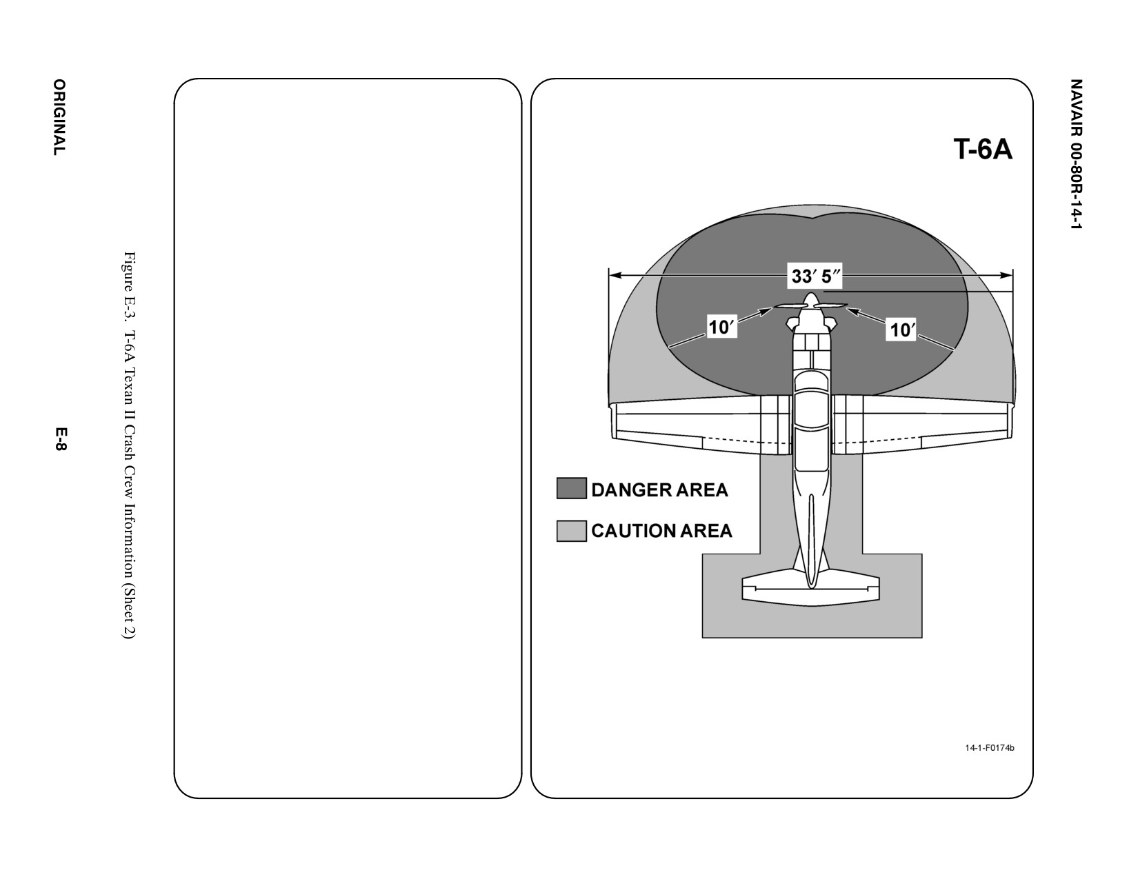
3. AIRCRAFT DANGER AREAS
Propeller/Prop Wash — 10i
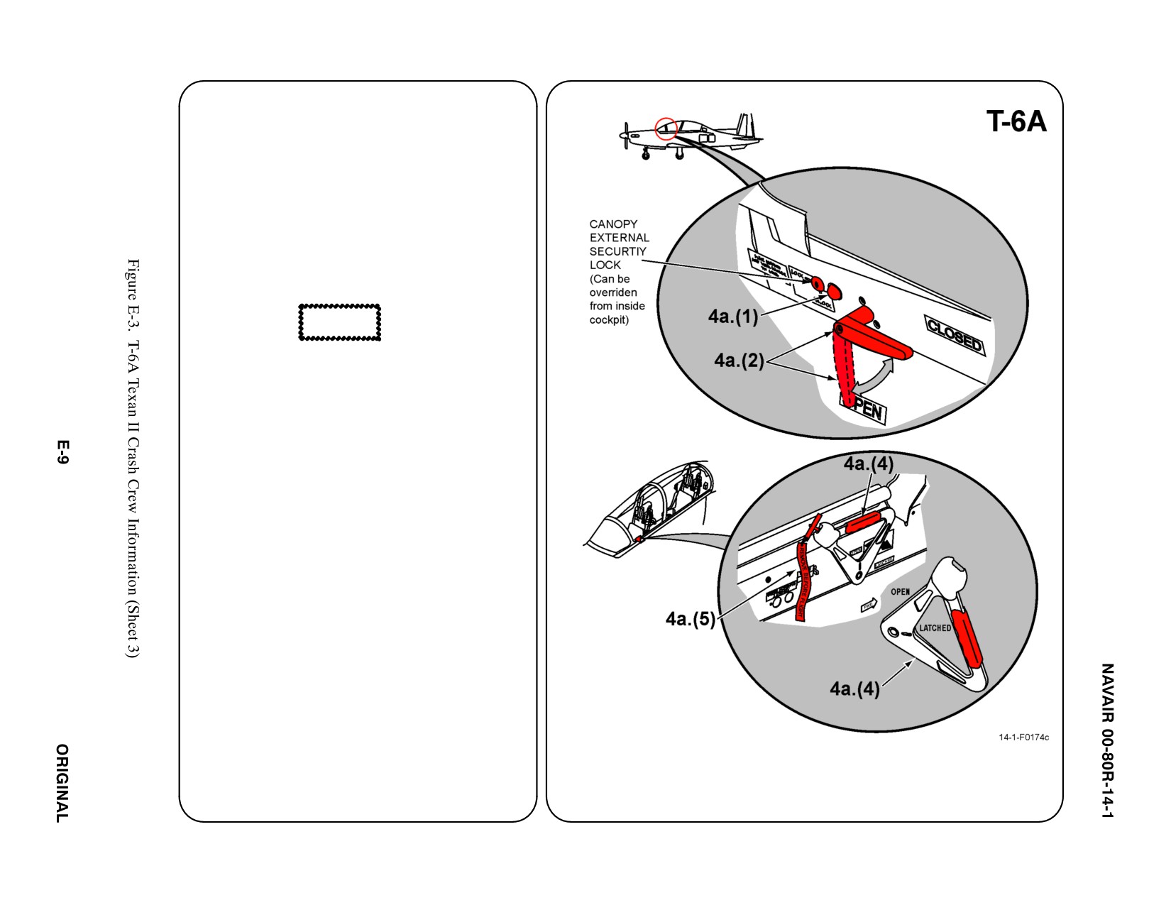
4. AIRCRAFT ENTRY
a. NORMAL ENTRY
Note
Approach aircraft from left wing. Enter aircraft
from left side of fuselage where the canopy open
handle is located.
(1) Push unlock button, located forward of
canopy open handle, to unlock canopy.
(2) Rotate canopy open handle clockwise to
the open position.
CAUTION
The side opening canopy is not quickly opened.
It has a hydraulic control rod which makes rapid
opening difficult. Use a slow deliberate push
upward. Rapid upward movement will resist the
firefighter or responder.
Note
Canopy is secure when in the full open position
and will not need assitance.
(3) Lift canopy up using the open handle.
(4) Rotate the interior canopy locking
handle located on the left canopy sill, to
the CLOSED/LATCHED position.
(5) Normally, the ejection seat safety pin is
stored in the internal canopy locking
handle. Handle can be rotated with pin
installed.
(6) Safety the ejection seats.
b. N/A
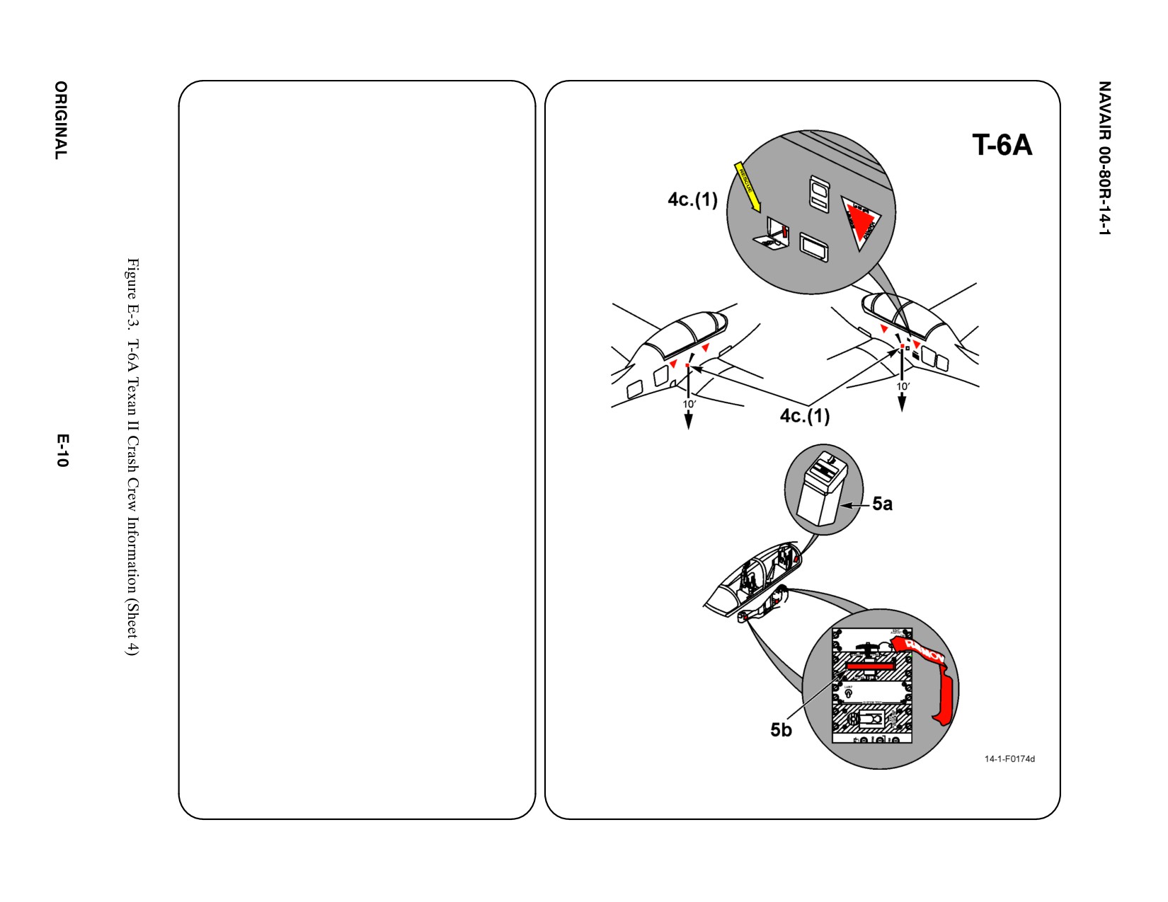
4. AIRCRAFT ENTRY (CONT.)
c. EMERGENCY ENTRY
Detonation cord is glued to inside of canopy.
Face away from aircraft when initiating system
due to possibility of flying fragments of canopy
plexiglass.
Note
Canopy fracturing system (CFS) is installed.
Canopy does not jettison.
(1) Open external emergency egress door,
located near either wing trailing edge on
side fuselage.
(2) Push latch on egress door, located on
either side fuselage under aft canopy sill.
(3) If CFS safety pin is installed, remove pin
and then remove T-handle by pulling
outward and aft.
(4) Pull T-handle and lanyard out to full
extension of 10 feet.
(5) Face away and pull sharply to initiate
canopy fracturing system. Both
transparencies will fracture and fall away.
d. FORCED ENTRY
If CFS system is inoperative, use power
rescue saw or crash ax to gain cockpit entry.
5.
CANOPY SAFETY
a. CFS safety pins are stored in the pin
storage box on the aft left cockpit bulkhead.
Remove pins from storage.
b. Insert CFS safety pins in the CFS handles
located on the left consoles in both cockpits.
If canopy can not be opened or fractured, cut
hole into canopy opposite interior handle, then
rotate the interior canopy locking handle,
located on the left canopy sill, to the
OPEN/UNLATCHED position. Handle can be
rotated with seat safety pin installed.
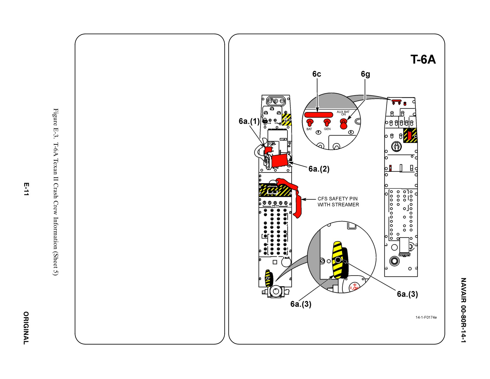
6. ENGINE SHUTDOWN
Note
Emergency engine shutdown (to include shutting
off fuel, hydraulics, and bleed air supply via the
firewall shutoff handle), can be accomplished in the
front cockpit only. If the front cockpit is not
accessible and the engine needs to be shutdown,
normal engine shutdown can also be
accomplished from the rear cockpit. (In the event
the front cockpit controls are not accessible or
damaged, and the engine is still running, the PCL
can also be placed to “OFF” from the rear cockpit.)
a.
FIRE SHUTDOWN
(1) Move power control lever (PCL) to idle
and raise finger tab (red lever labeled
”Engine Shutoff”), located on the
forward side of throttle handle.
(2) Retard power control handle (PCL),
located on left console, to full aft OFF
position.
(3) Remove metal clip and pull emergency
firewall shutoff handle, located on left aft
control panel of forward cockpit, to the
UP position.
b. N/A
c.
BATTERY
Place battery and generator gang switches,
located on right horizontal control panel, aft
or down to OFF position.
d. THROTTLE
e.
FUEL SELECTOR
f.
N/A
g. AUXILIARY POWER
Lift up and move auxiliary battery switch,
located right side battery/generator switch
on right console, aft to OFF position.
7.
N/A
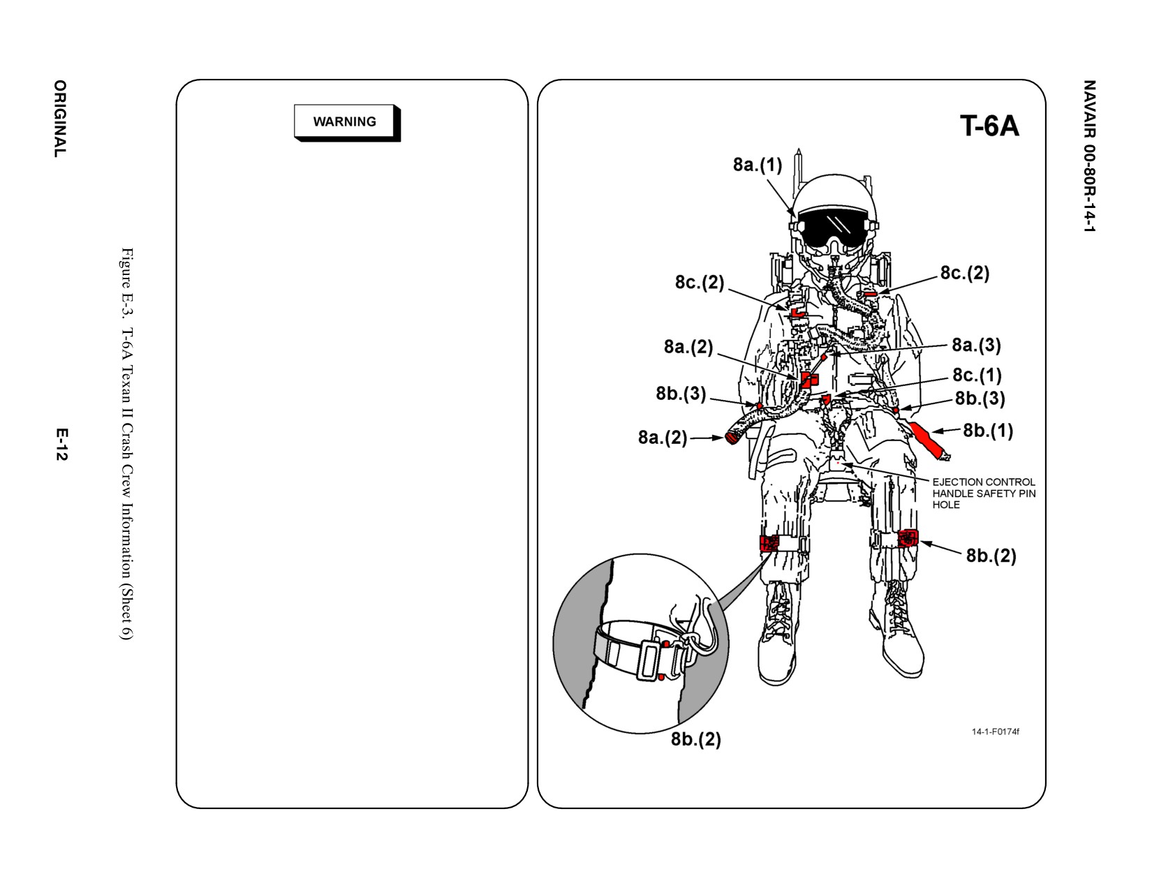
8. CREW RELEASE
Insure safety pins are installed in ejection control
handle of both seats and CFS handles to prevent
inadvertent seat ejection and detonation of the
canopy fracturing system.
a.
PERSONNEL SERVICE, QUICK
DISCONNECT
(1) Remove oxygen mask, if not previously
done.
(2) Disconnect oxygen and emergency
oxygen hoses, located on right side of
crew member, by pulling hoses apart.
(3) Disconnect communication lead, located
on oxygen hose, by pulling apart.
b. RESTRAINT SUIT BELTS/RELEASE
(1) Disconnect anti-G suit connection,
located on left side of crew member, by
pulling apart.
(2) Disconnect quick release connector on
right and left leg restraint garters at crew
member's shins by squeezing tabs
inward.
(3) Disconnect survival kit sticker clips from
left and right torso harness V-rings.
c.
HARNESS STRAPS/LEG RESTRAINT
RELEASE
(1) Unlatch lap belt connection and lay lap
belt halves aside.
(2) Unlatch right and left parachute
fittings/risers from torso harness and lay
shoulder harness straps aside.
Note
Torso harness contains strobe lights with batteries.
(3) Remove crew members carefully while
avoiding entanglement of legs in
equipment.
d. N/A
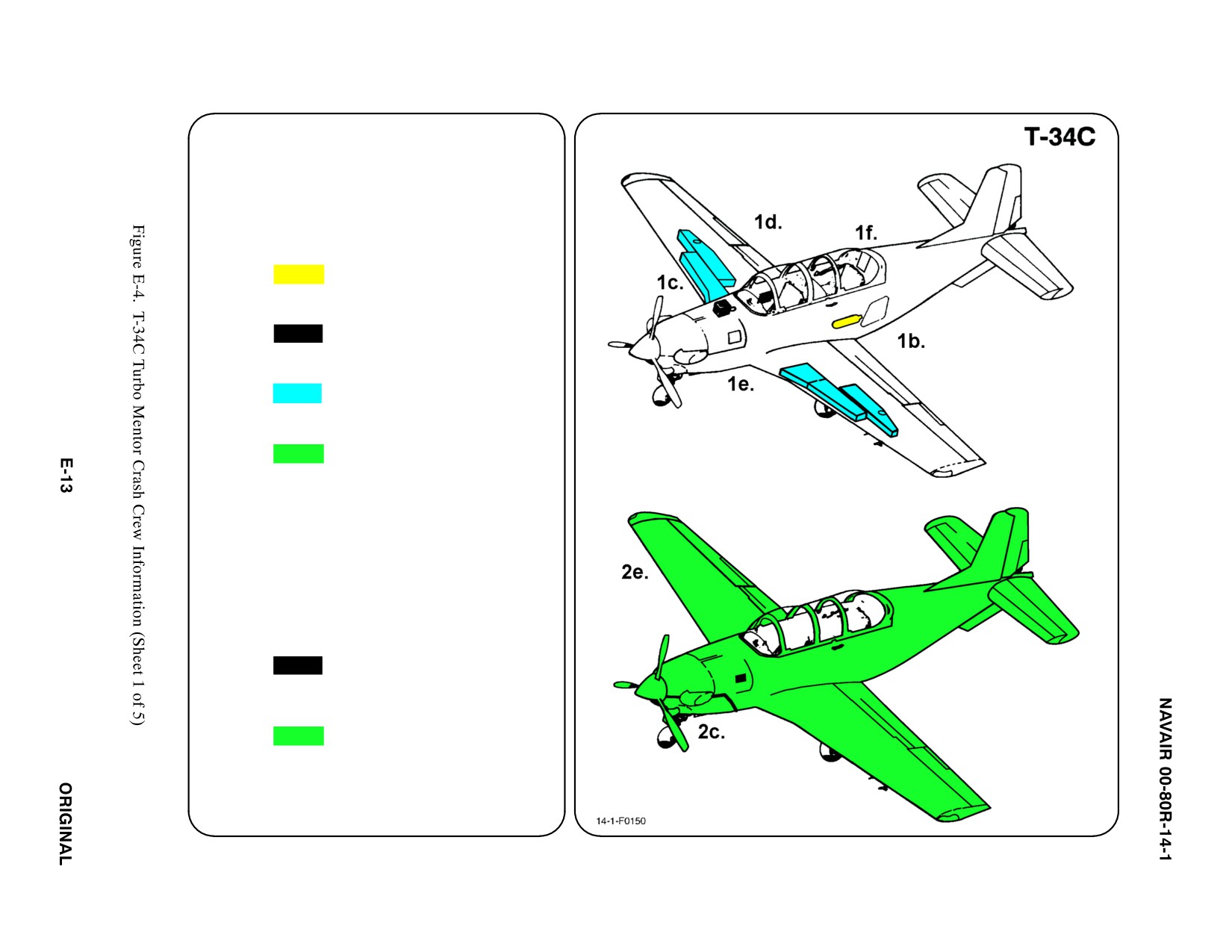
SPECIAL TOOLS/EQUIPMENT
Power Rescue Saw
Crash Axe
1. GENERAL AIRCRAFT INFORMATION
a. N/A
b. Oxygen Bottle
1 — 76ft3
c. Battery
1
d. Fuel
Internal 130 gal
e. Oil
Engine 4.4 gal
Brake Reservoir 1 pt
f. Pneumatic
3000 psi
ąSystem
2. AIRFRAME MATERIALS
a. N/A
b. N/A
c. Steel
d. N/A
e. Aluminum
f. N/A
g. N/A
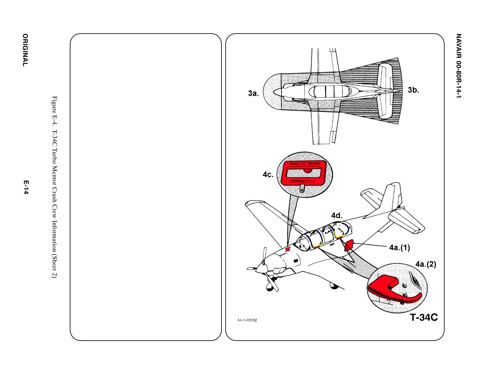
3. AIRCRAFT DANGER AREAS
a. Propeller/Prop Wash — 30i
b. Engine Exhaust Idle — 18i
Max Power — 30i
4. AIRCRAFT ENTRY
Note
D Entrance to and egress from both
cockpits is made from the left wing
since canopy handles and the aft
cockpit assist step are on the left side
only.
D The canopy is in three sections: a
manually-operated sliding section over
each cockpit, and a rigid center section.
Each sliding section opens aft and can
be operated independently.
a.
NORMAL ENTRY
(1) The aft cockpit kick step is located in the
fuselage above the trailing edge of the
left wing flap. Access to the step is from
the wing by kicking in a spring-loaded
door that is flush with the aircraft
exterior when closed.
(2) ROTATE Canopy Release Locking
Handle CLOCKWISE and PULL Canopy
Section AFT with Handle.
b. N/A
c.
EMERGENCY ENTRY (PNEUMATIC)
PULL Canopy Release Handle, located on
RH FWD fuselage marked with yellow
Rescue Arrow, to release both sets of
Canopy Rails from fuselage. REMOVE
Canopies.
d. FORCED ENTRY
Canopies are made of acrylic plastic. CUT
around Canopy Frames with power rescue
saw or crash ax.
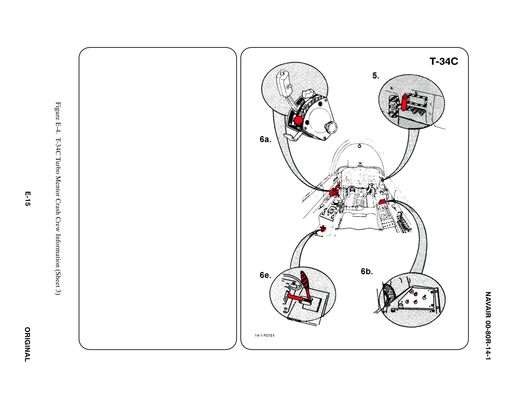
5.
CANOPY SAFETY
The interior Emergency Canopy Handle
presents no hazard to rescue personnel. A
metal clip holds the Handle securely in place.
a. N/A
b. N/A
6.
ENGINE SHUTDOWN
a. CONDITION LEVER
PULL Condition Lever AFT to OFF position.
b. BATTERY SWITCH
PLACE Battery Switch in the OFF position.
c. N/A
d. N/A
e. EMERGENCY FUEL SHUTOFF
RAISE Guard, PULL UP on Emergency
Fuel Shutoff Handle.
f. N/A
g. N/A
7.
BATTERY
The Battery is accessible through an Access
Door on the RH fuselage just FWD of the
Canopy. The Battery is equipped with a Quick
Disconnect Fitting. DISCONNECT, time
permitting.
a. N/A
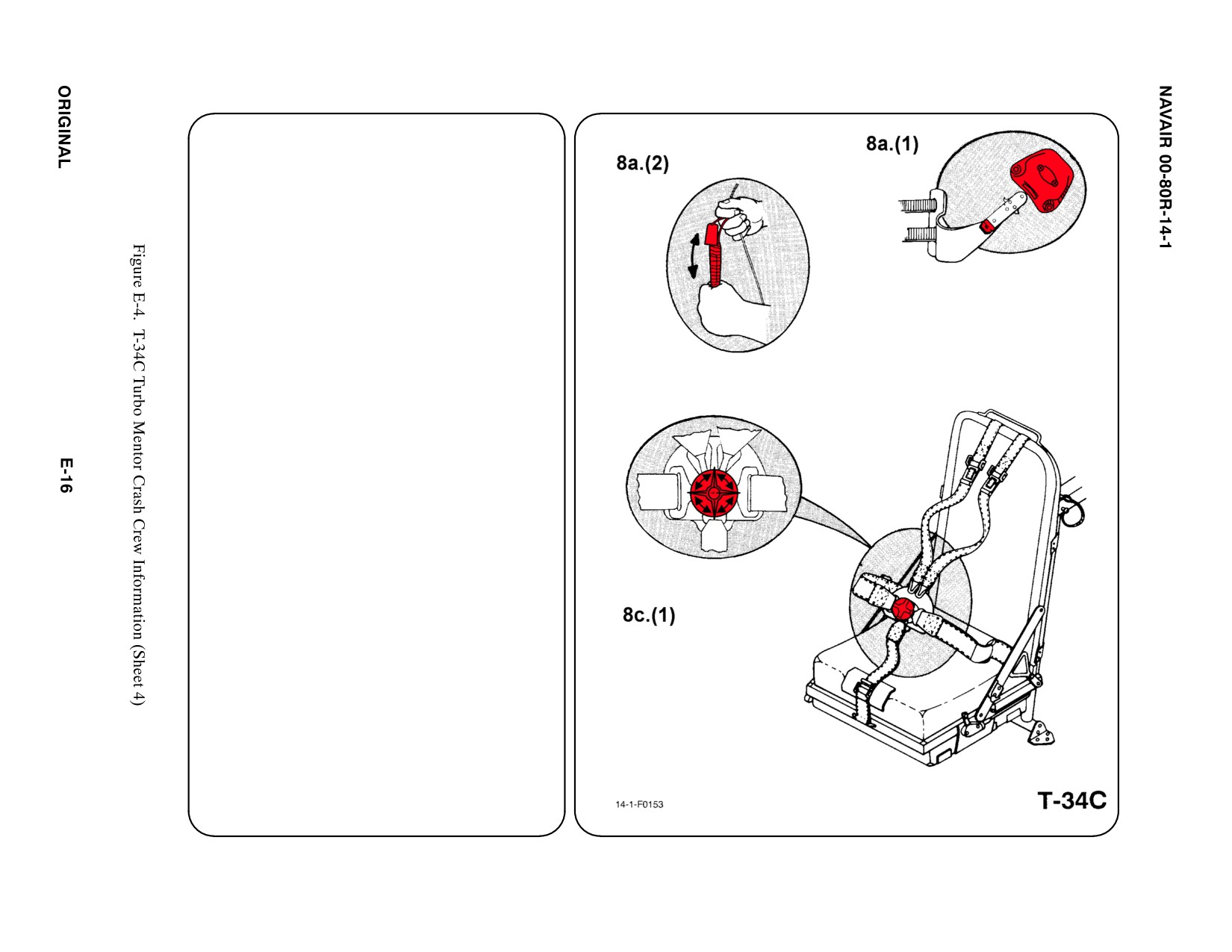
8. CREW RELEASE
Pilot seats are equipped with shoulder
harnesses, lap belts, and crotch straps utilizing
a single five point quick disconnect buckle.
Communication leads and oxygen hoses are
attached to the RH console and have quick
disconnects. Crewmembers wear NB-6
backpack parachutes which have static lines
attached to the LH side of the seats with red
spring clips.
a. PERSONNEL SERVICE, QUICK
DISCONNECT
(1) Remove oxygen mask by pulling down
on bayonet fittings on both sides of
mask.
(2) Disconnect communication leads by
pulling apart quick disconnect attached
to LH shoulder straps.
Note
Position oxygen mask hose assembly to the RH
console to remit unobstructed path for extraction
of crewmember.
b. N/A
c. HARNESS STRAPS/LEG RESTRAINT
RELEASE
(1) Rotate single point buckle in either
direction to release shoulder harness,
lap belt and crotch strap.1234567
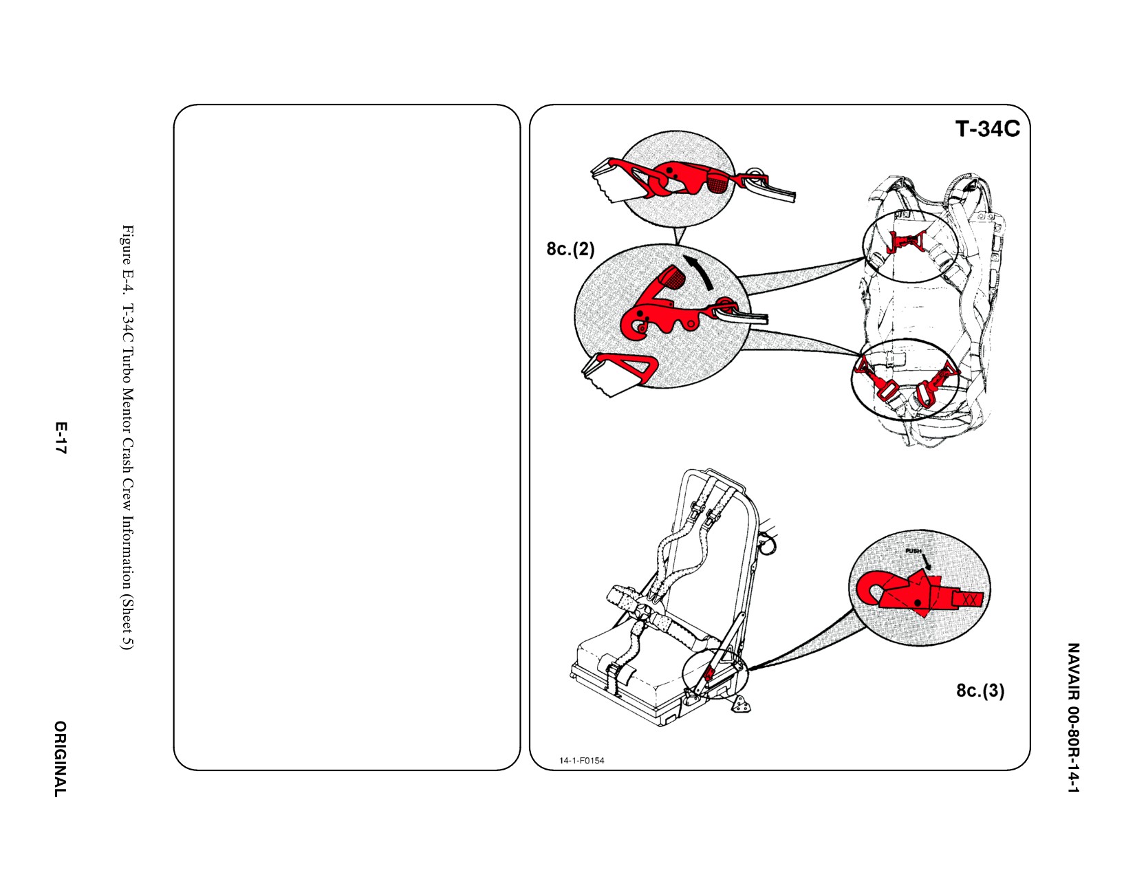
8. CREW RELEASE (CONT.) ab
c. HARNESS STRAPS/LEG RESTRAINT
RELEASE (CONT.) (1)
(2) Pull out on three parachute ejector snap
release levers one on each leg and one
on chest.
(3) If parachute cannot be released,
crewmember may be removed from
aircraft with parachute attached.
Release static line spring clip from LH
side of seat before removing
crewmember.
d. N/A
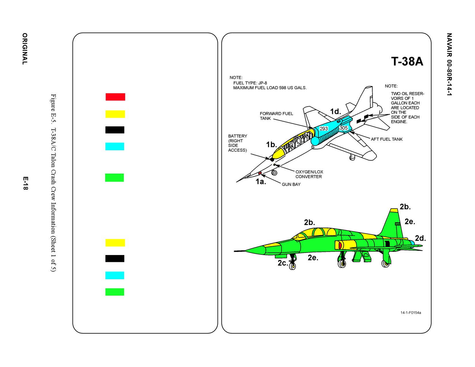
SPECIAL TOOLS/EQUIPMENT
Dearming Tool
Power Rescue Saw
Safety Pin P/N 50615
Fire Drill II
1. GENERAL AIRCRAFT INFORMATION
a. Armament
Gun bays both sides
b. Oxygen/LOX
5 L
c. Battery
1
d. Fuel
Forward 293 gal
Aft 305 gal
e. Oil
2 1 gal oil reservoirs
on each side of engine
f. N/A
2. AIRFRAME MATERIALS
a. N/A
b. Other
Plexiglass
Magnesium
c. Steel
d. Titanium
e. Aluminum
f. N/A
g. N/A
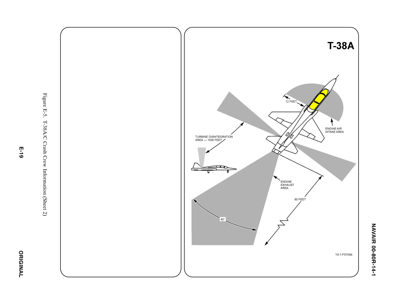
3. AIRCRAFT DANGER AREAS
a. Engine Air Intake Area — 25i
b. Engine Exhaust Idle — 50i
Max Power — 200i
c. Turbine Hazard Area — 1500i
d. Pitot Tube Hazard — Unpainted area could
be hot and can puncture
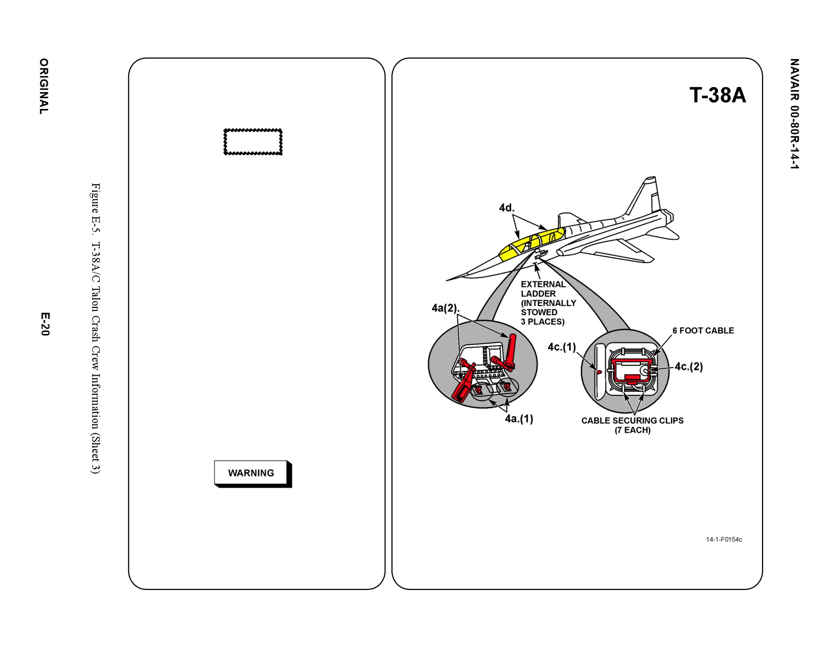
4. AIRCRAFT ENTRY
a. NORMAL ENTRY
(1) Push latches to open door, located on
left side of fuselage.
CAUTION
Opening canopy under windy conditions could
cause inadvertant canopy separation from aircraft.
(2) Pull handle(s) out until engaged and
rotate clockwise to unlock and raise
canopy, give canopy assistance while
rotating handle.
Note
Canopies are secure when raised to full open
position.
b. N/A
c. EMERGENCY ENTRY
(1) Push latch on canopy jettison access
door, located on left and right side of
forward fuselage, to open.
(2) Pull canopy jettison D-handle,
approximately 6 feet to jettison both
canopies.
d. FORCED ENTRY
Cut canopy along canopy frame on all 4
sides.
5. CANOPY SAFETY
If emergency canopy jettisonT-handle has been
actuated, but canopy has not jettisoned, cut
canopy hose at top aft of seat structure to prevent
inadvertant canopy jettison.
a. N/A
b. N/A
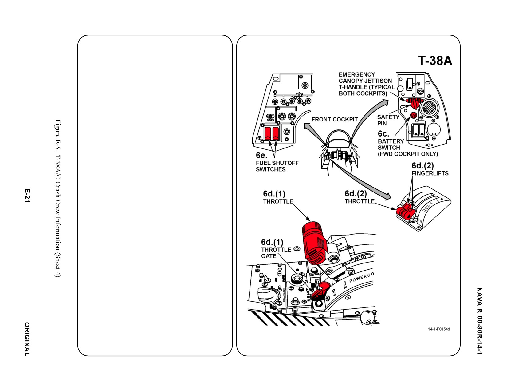
6. ENGINE SHUTDOWN
Note
AETC operated aircraft have a throttle gate
installed on the aft portion of the throttle console
in the forward cockpit. The throttle gate must be
disengaged prior to proceeding.
a. N/A
b. N/A
c. BATTERY
Place battery switch, located on right
vertical control panel, down to OFF position.
Note
D
Engines can be throttled to idle from rear
cockpit.
D
If engines fail to shutdown, turn battery
switch ON and place fuel shutoff switches,
located on left vertical panel, to CLOSED
position. Place battery switch to OFF
position.
d. THROTTLE
(1) For AETC aircraft only: Disengage
throttle gate by pushing the red release
arm inboard (toward ejection seat).
(2) For conventional aircraft: Raise finger lift
and retard throttle, located on left
console panel, to full aft OFF position.
e. FUEL SELECTOR
Push red guards down and place fuel
shutoff switches to closed position. Wait 10
seconds for fuel valve to operate.
f. N/A
g. N/A
7. BATTERY
Battery is located right side access.
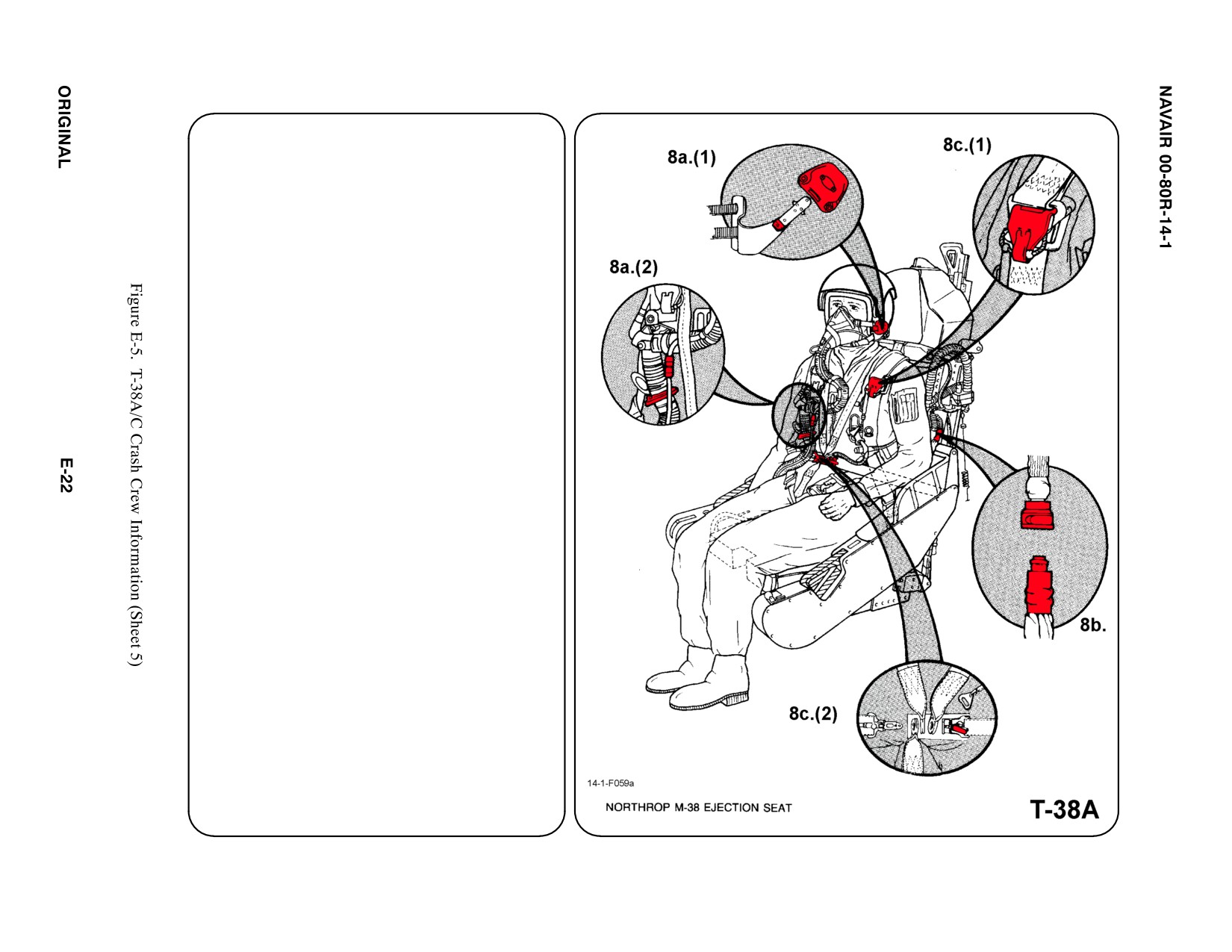
8.
CREW RELEASE
The crewmembers are attached to the seat by
shoulder straps which are attached to the lap
belt by a quick release fitting. Additionally,
there are oxygen/communication leads and
anti-G suit hose attachments.
a. PERSONNEL SERVICE, QUICK
DISCONNECT
(1) Remove oxygen mask by PULLING
DOWN on release tabs on either side of
mask.
(2) Disconnect oxygen hose and commu-
nication lead at disconnection points.
b. RESTRAINT SUIT BELTS/RELEASE
PULL anti-G suit hose from fitting connected
to the LH side of seat.
c. HARNESS STRAPS/LEG RESTRAINT
RELEASE
(1) Release both parachute riser straps.
(2) SQUEEZE and RAISE Manual Release
Lever on lap belt buckle.
Note
The survival kit disconnect buckles may be
obscured from view.
Locate lap belt and follow it to the general
area of the Survival Kit disconnect buckles.
PRESS Push to Release tab in center of
each buckle to release.
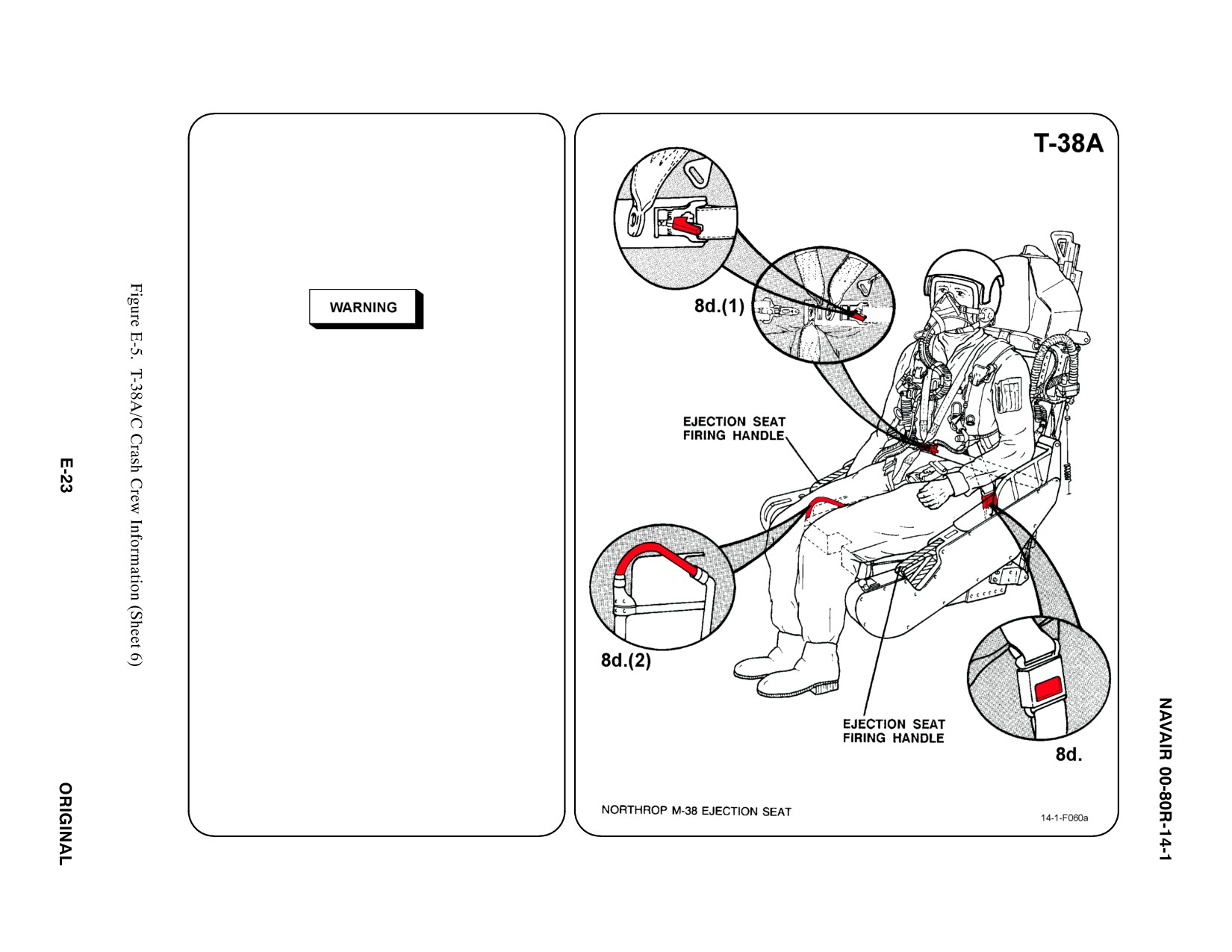
8. CREW RELEASE (CONT.)
d. EMERGENCY RELEASE
(1) RESTRAINTS
SQUEEZE and RAISE Manual Release
Lever on lap belt buckle.
(2) EMERGENCY RELEASE HANDLE
The Emergency Release Handle (see illustration
8d(2).) looks similar to the Ejection Seat Firing
Handles and may be obscured by the pilot's right
leg. DO NOT pull the Ejection Seat Firing Handle.
This may be fatal to crewmembers and rescue
personnel.
(a) PULL Emergency Release Handle
with pilot's weight on seat. Parachute
will remain attached.
Note
Ensure parachute ripcord does not snag when
removing pilot from cockpit.
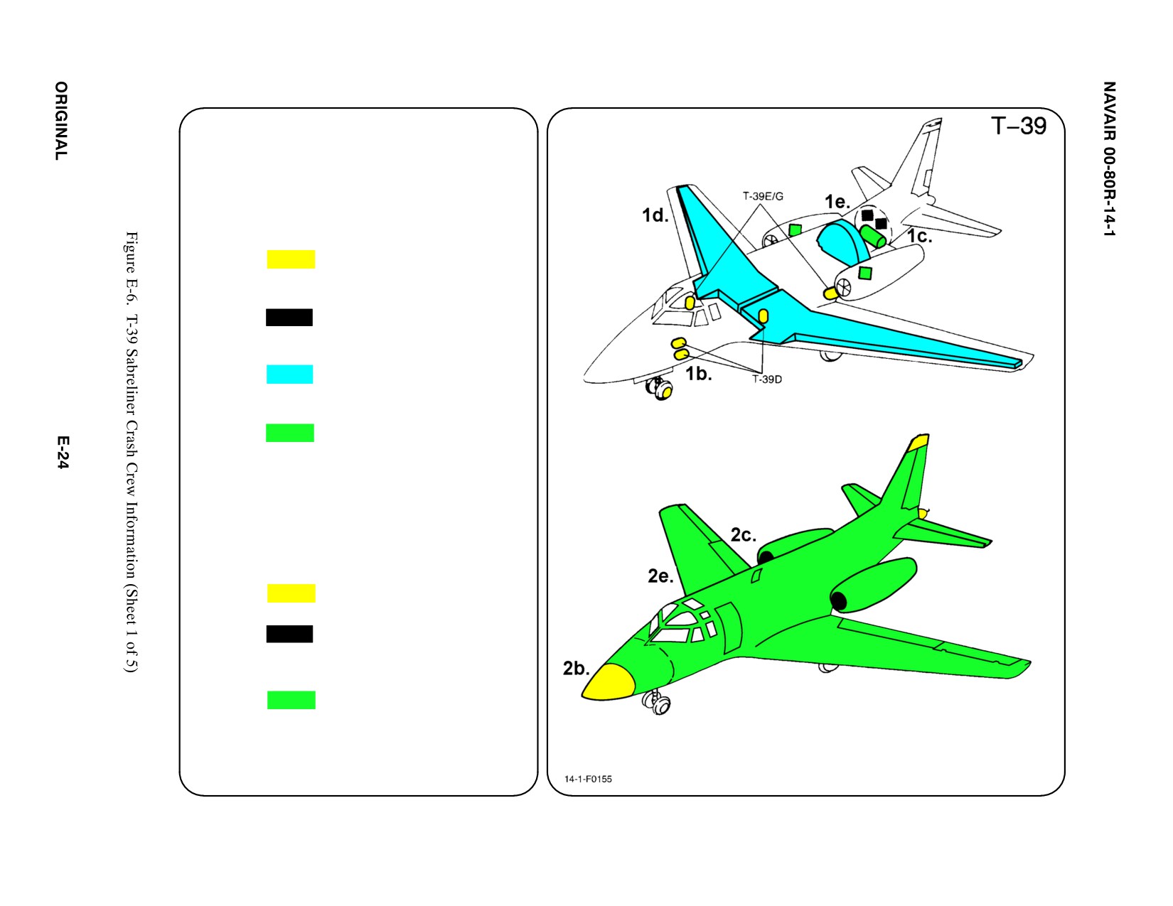
SPECIAL TOOLS/EQUIPMENT
Power Rescue Saw
Crash Axe
1. GENERAL AIRCRAFT INFORMATION
a. N/A
b. Oxygen/LOX
78.4 ft3
c. Battery
2
d. Fuel
Internal 1100 gal
e. Oil
Engine 3.2 gal
Hydraulic 2.6 gal
f. Pneumatic
3000 PSI
ąSystem
2. AIRFRAME MATERIALS
a. N/A
b. Other
Fiberglass/Magnesium
c. Steel
d. N/A
e. Aluminum
f. N/A
g. N/A
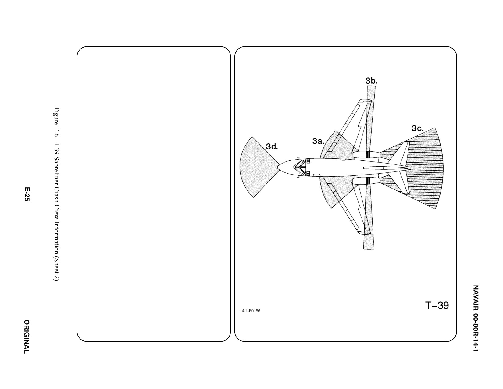
3. AIRCRAFT DANGER AREAS
a. Inlet Suction — 12i
b. Turbine Blade Failure — 300i
c. Engine Exhaust
ąIdle — 60i
ąMax — 100i
d. Radiation
ąFWD 110_ Arc — 150i
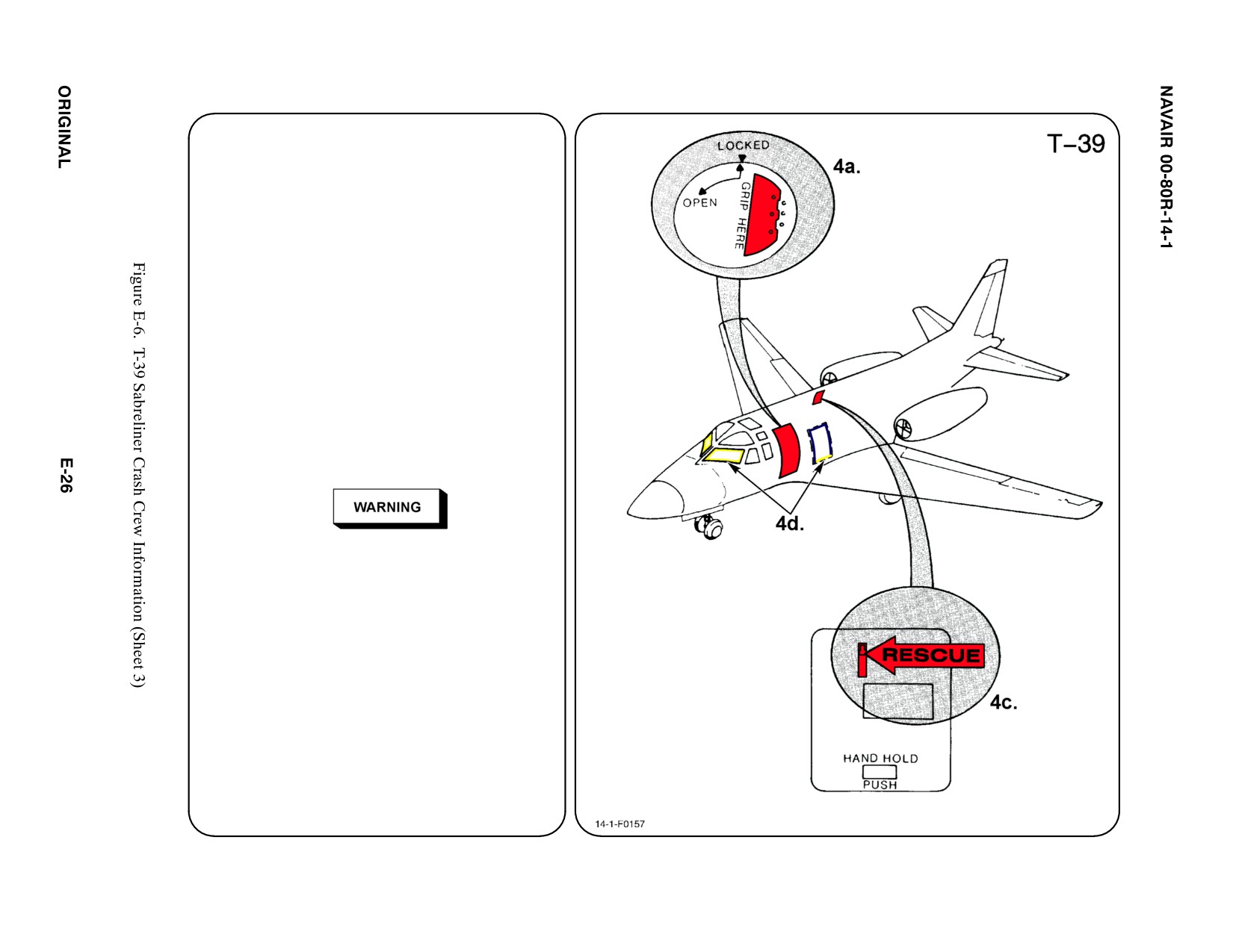
4. AIRCRAFT ENTRY
a. NORMAL ENTRY
TURN Rotary Latch, located FWD LH side
of fuselage, One Quarter Turn
COUNTERCLOCKWISE to UNLOCK Main
Entrance Door. APPLY EVEN PRESSURE
on lower section of door. Door will move
inward several inches and then top of door
will rotate outward and start a downward
swing. When door starts downward
movement, SUPPORT door and LOWER
to extended position.
b. N/A
c. EMERGENCY ENTRY
If the Main Entrance Doorway is
inaccessible, enter through the Ground
Escape Hatch located on RH side of
fuselage just FWD of the engine intake.
This entrance lies within the danger
area for the engine intake suction area.
PUSH Release Button, located RH side of
fuselage over wing, and PULL handle to
unlock escape hatch. PUSH escape hatch
IN to gain entry.
d. FORCED ENTRY
If the door or escape hatch are
inaccessible, the chopping or cutting area
that would offer the least resistance is the
area immediately AFT of the Main
Entrance Doorway. This area may or may
not be marked on the aircraft.
5. N/A
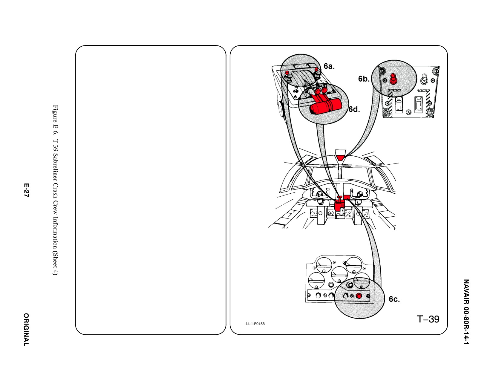
6.
ENGINE SHUTDOWN
a. ENGINE MASTER SWITCHES
PLACE Electrical Master Switch in OFF
position (positive lock type).
b. ELECTRICAL MASTER SWITCH
PLACE Electrical Master Switch in OFF
position (positive lock type).
c. BATTERY SWITCH
PLACE Battery Switch in OFF position.
d. THROTTLE
DEPRESS Throttle Safety Latches and
RETARD Throttles to CLOSE position.
e. N/A
f. N/A
g. N/A
7.
BATTERY
Two batteries are located in the AFT fuselage
compartment and are accessible through the
AFT compartment access door. This door will
be inaccessible if the aircraft is on its belly.
a. N/A
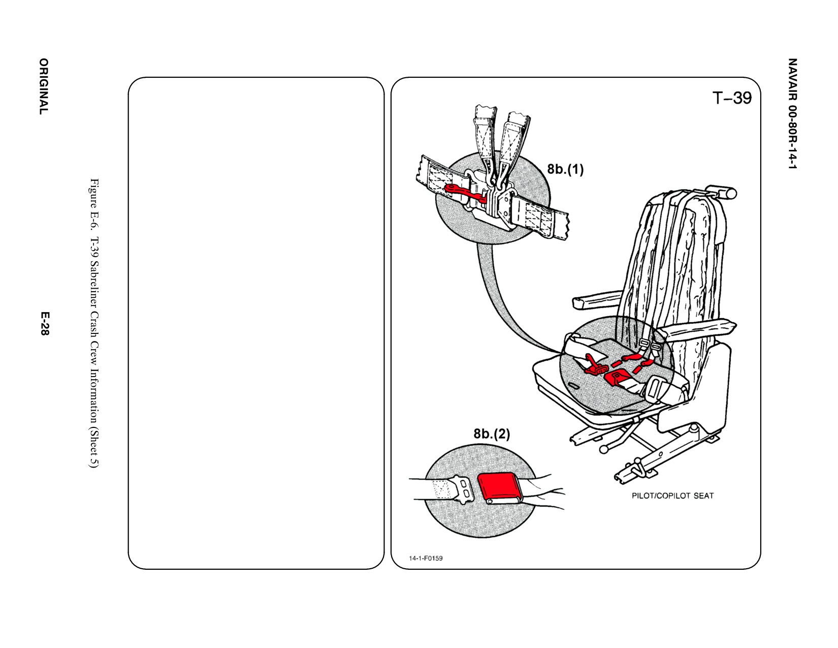
8. CREW RELEASE
The pilot and copilot are attached to the
seats by shoulder harnesses and lap belts.
Passengers and crew have lap belts only.
a. N/A
b. RESTRAINT SUIT BELTS/RELEASE
(1) Lift quick disconnect lever to release
shoulder harnesses and lap belt.
(2) PASSENGER; Lift buckle cover to
release lap belt (airline type).
c. N/A
d. N/A
SPECIAL TOOLS/EQUIPMENT
Power Rescue Saw
Crash Axe
1. GENERAL AIRCRAFT INFORMATION
a. N/A
b. Oxygen/LOX
49 ft3
c. Battery
1
d. Fuel
Internal 388 gal
e. Oil
Engine 2.3 gal
Hydraulic 1 pt
f. N/A
2. AIRFRAME MATERIALS
a. N/A
b. Other
ąFiberglass/Magnesium
c. Steel
d. N/A
e. Aluminum
f. N/A
g. N/A
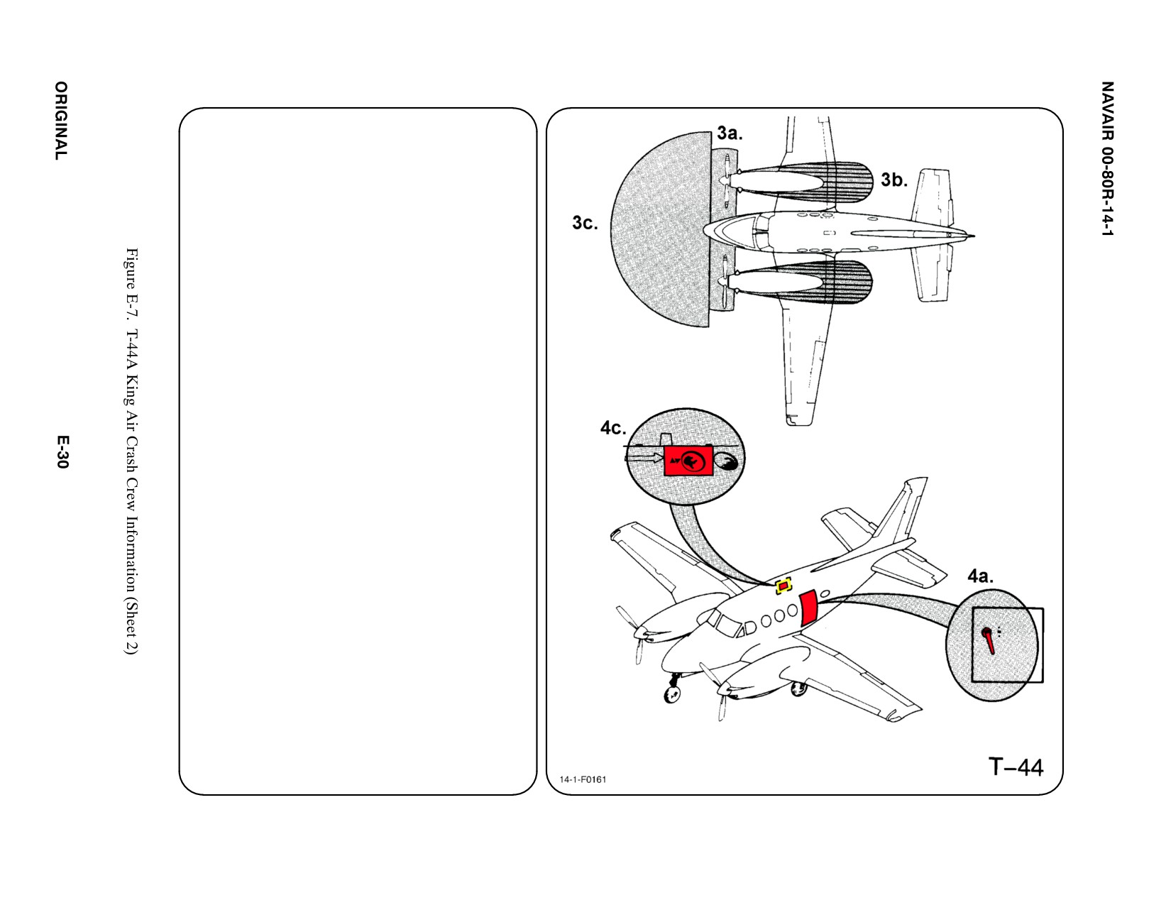
3.
AIRCRAFT DANGER AREAS
a. Propeller Danger Zone — 15i
b. Engine Exhaust — 20i
c. Radiation FWD 180_ Arc — 18i
4.
AIRCRAFT ENTRY
a. NORMAL ENTRY
Normal entry is through the cabin door
located AFT of the wing on the LH side of
the fuselage. PRESS button behind the
handle and ROTATE the handle
CLOCKWISE to OPEN.
b. N/A
c. EMERGENCY/FORCED ENTRY
The Emergency Exit Hatch is located on
RH side of fuselage. Using crash axe,
BREAK window. REACH through,
REMOVE cover over release handle.
PRESS pushbutton below handle. PULL
handle INWARD and UP to release hatch.
d. N/A
5.
N/A
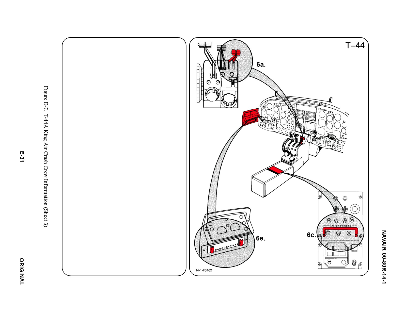
6.
ENGINE SHUTDOWN
a. CONDITION LEVERS
MOVE Condition Levers AFT to CUT-OFF
position.
b. N/A
c. BATTERY SWITCH
PLACE Battery Switch in the OFF position
by MOVING Master Gang Bar AFT.
d. N/A
e. FUEL VALVE SWITCHES
PLACE Fuel Valve Switches in CLOSED
position by RAISING guards and MOVING
switches DOWN.
f. N/A
g. N/A
7.
BATTERY
The battery is located in the top of the right
wing center section and equipped with a quick
disconnect plug.
a. N/A
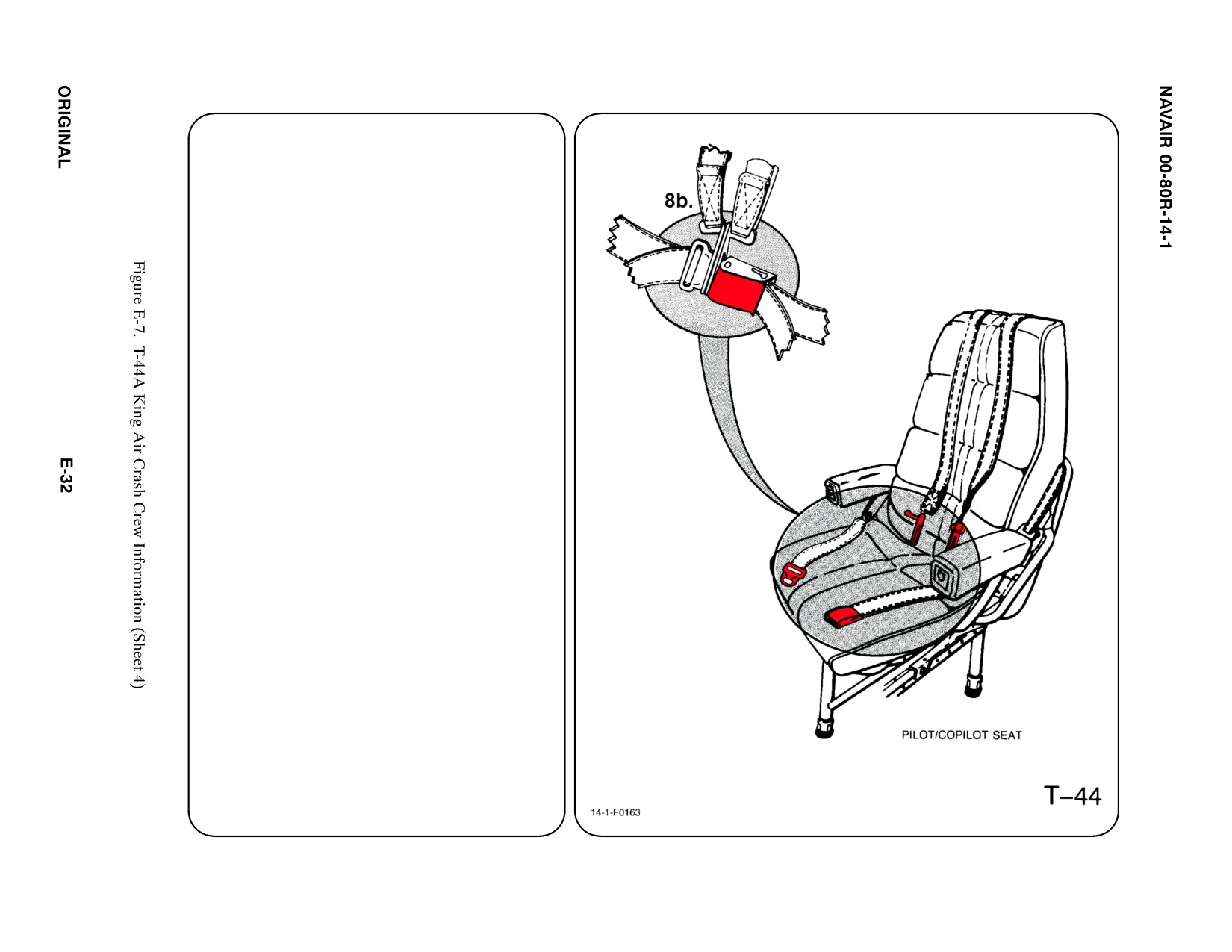
8. CREW RELEASE
The pilot and copilot are attached to the seats
by shoulder harnesses and lap belts.
Passengers have lap belts only.
a. N/A
b. RESTRAINT SUIT BELTS/RELEASE
Lift buckle cover to release shoulder
harnesses and lap belt.
c. N/A
d. N/A
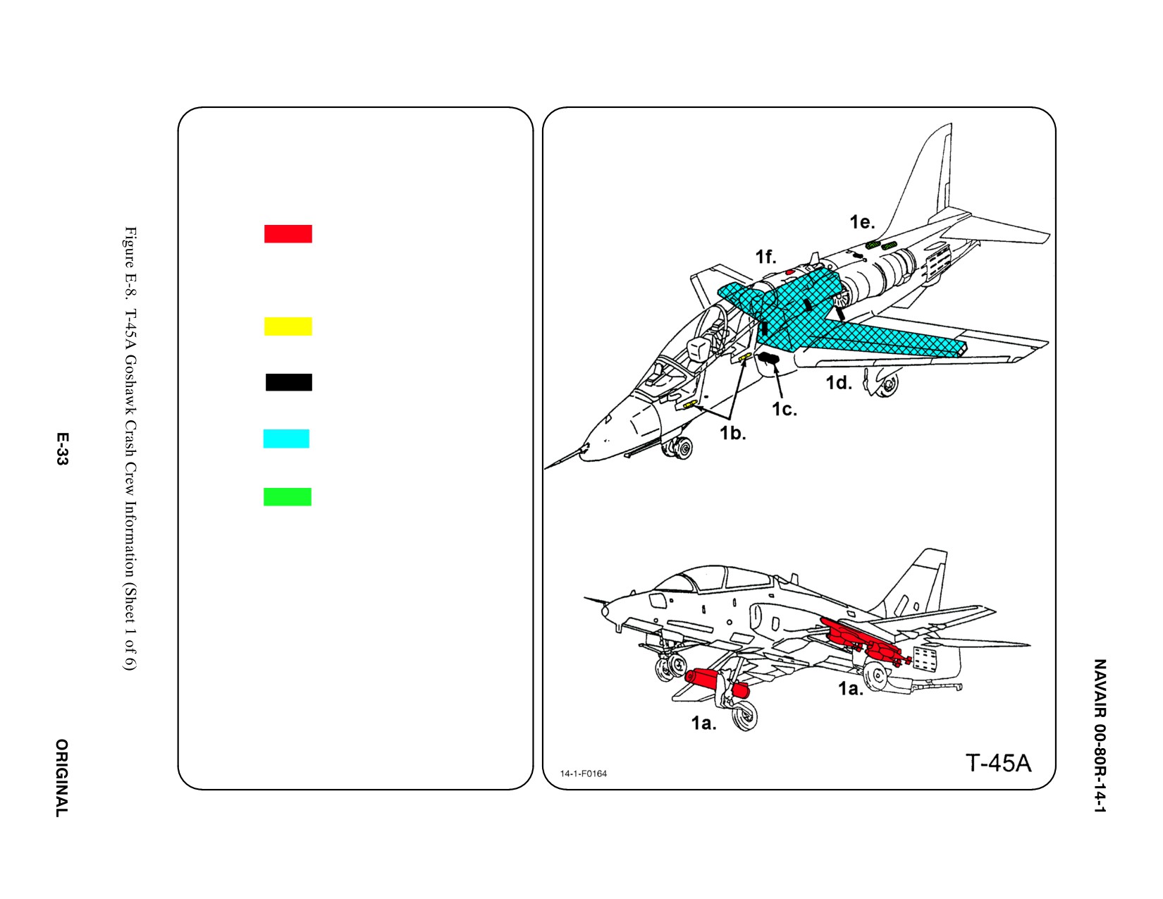
SPECIAL TOOLSIEQUIPMENT
Power Rescue Saw
Crash Axe
1. GENERAL AIRCRAFT INFORMATION
a. Armament
2 Wing Stations
Practice Bombs
Rockets
Pylon Ejector
Cartridges
b. Oxygen
OBOGS
Bailout Bottle (2)
(1 in each seat pan)
c. Battery
2
d. Fuel
Internal 433 gal
e. Oil/Hydraulic
2 Reservoirs
f. Pneumatic
3,000 PSI
ąSystem