MANUAL OF NATO SAFETY PRINCIPLES FOR THE STORAGE OF MILITARY AMMUNITION AND EXPLOSIVES (May 2010) - page 19
AASTP-1
(Edition 1)
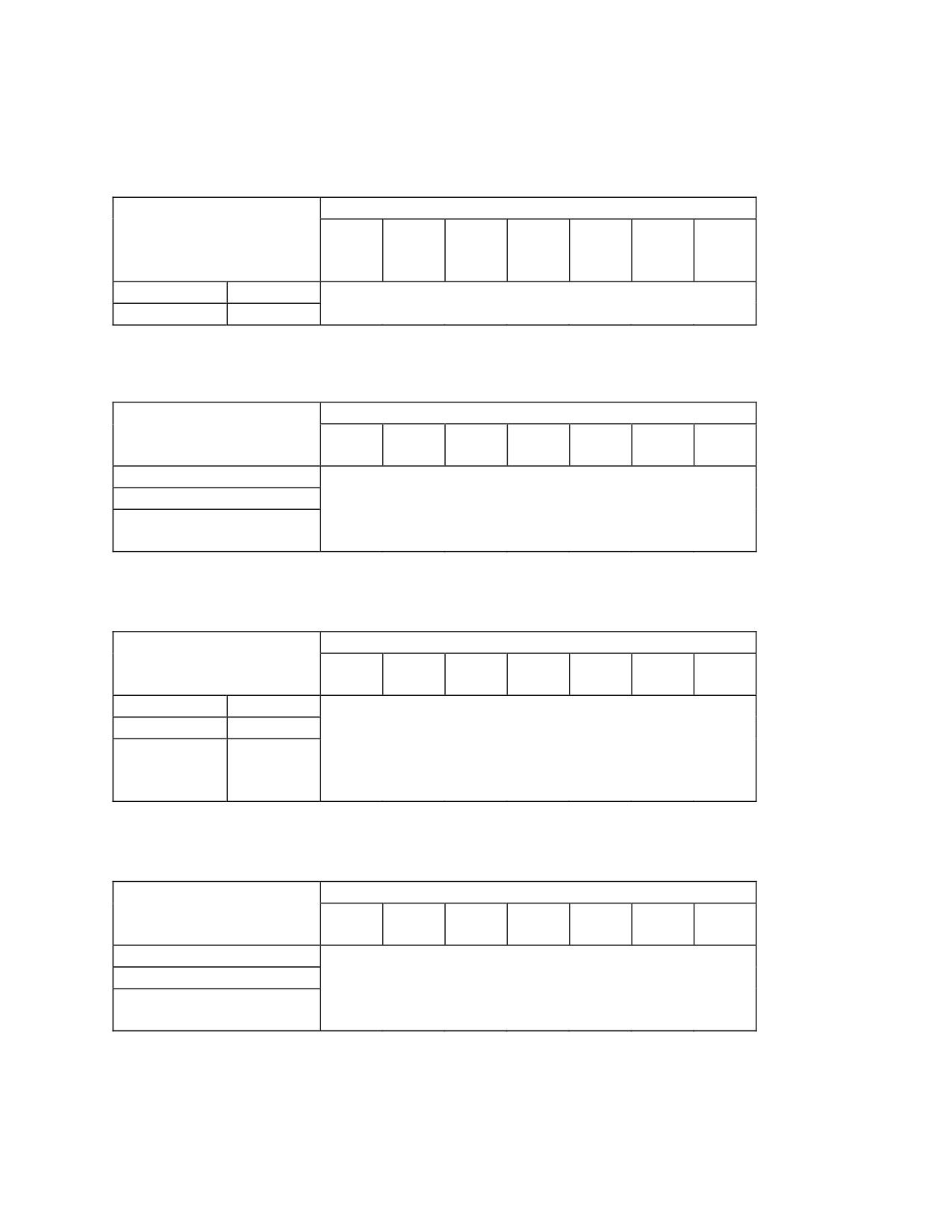
Table 1.2.1.a Minimum intermodule Q-Ds (in meters) for ammunition of HD1.1 stored in ISO containers or
equivalent.
Quantity-Distances for HD1.1
500
1 ton
5
10
15
20
25
kg
NEQ
tons
ton
ton
ton
ton
NEQ
NEQ
NEQ
NEQ
NEQ
NEQ
Unbarricaded
D= 4.8 Q1/3
39
48
83
105
120
135
145
Barricaded
D= 0.8 Q1/3
7
8
14
18
20
22
24
Table 12.1.b Minimum intermodule Q-Ds (in meters) for ammunition of HD1.2(.1 and .2) stored in ISO containers
or equivalent.
Quantity-Distances for HD1.2
500 kg
1 ton
5 ton
10 ton
15 ton
20 ton
25 ton
NEQ
NEQ
NEQ
NEQ
NEQ
NEQ
NEQ
Unbarricaded
10
10
10
10
10
10
10
Barricaded
No QD
No QD
No QD
No QD
No QD
No QD
No QD
Barricaded and protective
No QD
No QD
No QD
No QD
No QD
No QD
No QD
roof
Table 1.2.1.c Minimum intermodule Q-Ds (in meters) for ammunition of HD1.3C stored in ISO containers or
equivalent.
Quantity-Distances for HD1.3C
500 kg
1 ton
5 ton
10 ton
15 ton
20 ton
25 ton
NEQ
NEQ
NEQ
NEQ
NEQ
NEQ
NEQ
Unbarricaded
D= 0.44 Q1/2
10
14
32
44
56
64
70
Barricaded
D= 0.22 Q1/2
5
7
16
22
28
32
35
Barricaded
-
No QD
No QD No QD
No QD
No QD
No QD
No QD
and protective
roof
Table 1.2.1.d Minimum intermodule Q-Ds (in meters) for ammunition of HD1.3G stored in ISO containers or
equivalent.
Quantity-Distances for HD1.3G
500 kg
1 ton
5 ton
10 ton
15 ton
20 ton
25 ton
NEQ
NEQ
NEQ
NEQ
NEQ
NEQ
NEQ
Unbarricaded
10
10
10
10
10
10
10
Barricaded
No QD
No QD
No QD
No QD
No QD
No QD
No QD
Barricaded and protective
No QD
No QD
No QD
No QD
No QD
No QD
No QD
roof
-IV-2-12-
Change 3

AASTP-1
(Edition 1)
b)
Exterior Quantity-Distances
Specific types of exposed sites as they appear in the theatre of operations are redefined and classified into their
vulnerability to explosion effects. They are subdivided into military and civil ones (see table 1.2.2.a).
Table 1.2.2.a Definitions of exposed sites in the exterior military and civil zone.
Exposed site
Examples
Unprotected
Personnel in:
personnel
the open, standard vehicles, tents,
light structures, field hospitals, etc.
Semi-protected
Personnel in strengthened structures
personnel
Protected
Personnel in:
personnel
protective shelter, armoured vehicles
(like YPR-765), etc.
Unprotected
-
POL-installation
Protected POL-
POL-installation with protective
installation
measures, e.g. Hesco Bastions and
protective roof construction
Unprotected
People in:
civilians
the open, houses, cars, etc.
Chemical
-
industry
“Semi-protected personnel” refers to personnel in strengthened structures. Examples are:
1. accommodations in which the normal glazing is replaced by air blast- and bullet resistant glazing;
2. accommodations which are equipped with bullet (SAA) resistant panels;
3. strengthened roof constructions (e.g. earth covered 20 ft flatracks).
“Protected personnel” refer to personnel in bunkers and armoured vehicles. This type of structures must be able to
resist explosion effects like ammunition fragments and air blast with a peak incident overpressure of 21 kPa
(corresponding with a protection level of 8.0 Q1/3).
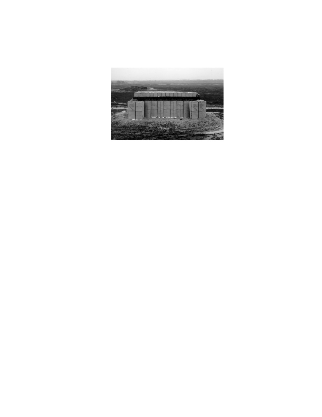
An example of a field protective shelter is shown in figure 1.2.2.a. Protection is given by walls of Hesco Bastion
Concertainers and a protective roof which is made of small Hesco Bastion Concertainers filled with sand with on
-IV-2-13-
Change 3
AASTP-1
(Edition 1)
top of that a burster layer. Inside this heavy structure, a 20 ft iso-container is placed to offer personnel some
comfort.
Figure 1.2.2.a
Example of protective shelter.
Minimum exterior Q-Ds for ammunition and explosives of HD1.1, HD1.2(.1 and .2) and HD1.3 are given in the
following tables.
-IV-2-14-
Change 3

AASTP-1
(Edition 1)
Table 1.2.2.b Minimum exterior distances (in meters) from a PES with ammunition of HD1.1.
Quantity-Distances for HD1.1
Exposed Site
Protection
500 kg
1 ton
5 ton
10 ton
15 ton
20 ton
25 ton
level
NEQ
NEQ
NEQ
NEQ
NEQ
NEQ
NEQ
Unprotected personnel
D=
22.2
180
225
380
480
550
610
650
Q1/3
Semi-protected
D=
14.8
120
150
255
320
365
405
435
personnel
Q1/3
Protected personnel
D= 8.0 Q1/3
64
80
140
175
200
220
235
Unprotected
POL-
D=
22.2
180
225
380
480
550
610
650
installation
Q1/3
Protected
POL-
D= 1.2 Q1/3
10
12
21
26
30
33
36
installation
Unprotected civilian
D=
22.2
180
225
380
480
550
610
650
Q1/3
Chemical industry
D=
22.2
180
225
380
480
550
610
650
Q1/3
-IV-2-15-
Change 3

AASTP-1
(Edition 1)
Table 1.2.2.c Minimum exterior distances (in meters)from an unbarricaded open stack or light structure (e.g. ISO
container) PES with ammunition of HD1.2.1.
Quantity-Distances for HD1.2.1
Exposed Site
Protection
500 kg
1 ton
5 ton
10 ton
15 ton
20 ton
25 ton
level
NEQ
NEQ
NEQ
NEQ
NEQ
NEQ
NEQ
Unprotected personnel
D2*
220
257
337
370
389
402
412
Semi-protected
D6*
148
173
226
248
261
270
277
personnel
Protected personnel
N/A
No QD No QD No QD No QD No QD No QD No QD
Unprotected
POL-
D2*
220
257
337
370
389
402
412
installation
Protected
POL-
N/A
No QD
No QD
No QD
No QD
No QD
No QD
No QD
installation
Unprotected civilian
D2*
220
257
337
370
389
402
412
Chemical industry
D2*
220
257
337
370
389
402
412
* Ref. [10].
Table 1.2.2.d Minimum exterior distances (in meters) from an unbarricaded open stack or light structure (e.g. ISO
container) PES with ammunition of HD1.2.2.
Quantity-Distances for HD1.2.2
Exposed Site
Protection
500 kg
1 ton
5 ton
10 ton
15 ton
20 ton
25 ton
level
NEQ
NEQ
NEQ
NEQ
NEQ
NEQ
NEQ
Unprotected personnel
D1*
75
88
123
141
152
160
166
Semi-protected
D5*
60
60
83
95
103
108
112
personnel
Protected personnel
N/A
No QD No QD No QD No QD No QD No QD No QD
Unprotected
POL-
D1*
75
88
123
141
152
160
166
installation
Protected
POL-
N/A
No QD
No QD
No QD
No QD
No QD
No QD
No QD
installation
Unprotected civilian
D1*
75
88
123
141
152
160
166
Chemical industry
D1*
75
88
123
141
152
160
166
* Ref. [10].
-IV-2-16-
Change 3

AASTP-1
(Edition 1)
Table 1.2.2.e Minimum exterior distances (in meters) from the side- and rear walls of earth covered PES with
ammunition of HD1.2(.1 and .2).
Quantity-Distances for HD1.2(.1 and .2)
Exposed Site
Protection
500 kg
1 ton
5 ton
10 ton
15 ton
20 ton
25 ton
level
NEQ
NEQ
NEQ
NEQ
NEQ
NEQ
NEQ
Unprotected personnel
IBD*
60
60
60
60
60
60
60
Semi-protected
PTRD*
60
60
60
60
60
60
60
personnel
Protected personnel
EWD*
No QD No QD No QD No QD No QD No QD No QD
Unprotected
POL-
IBD*
60
60
60
60
60
60
60
installation
Protected
POL-
N/A
No QD
No QD
No QD
No QD
No QD
No QD
No QD
installation
Unprotected civilian
IBD*
60
60
60
60
60
60
60
Chemical industry
IBD*
60
60
60
60
60
60
60
* Ref. [10].
Table 1.2.2.f Minimum exterior distances (in meters) from a PES with ammunition of HD1.3C.
Quantity-Distances for HD1.3C
Exposed Site
Protection
500 kg
1 ton
5 ton
10 ton
15 ton
20 ton
25 ton
level
NEQ
NEQ
NEQ
NEQ
NEQ
NEQ
NEQ
Unprotected personnel
D= 6.4 Q1/3
51
64
110
140
160
175
190
Semi-protected
D= 4.3 Q1/3
35
43
73
92
110
120
125
personnel
Protected personnel
D= 3.2 Q1/3
26
32
55
68
80
87
94
Unprotected
POL-
D= 6.4 Q1/3
51
64
110
140
160
175
190
installation
Protected
POL-
D= 3.2 Q1/3
26
32
55
68
80
87
94
installation
Unprotected civilian
D= 6.4 Q1/3
51
64
110
140
160
175
190
Chemical industry
D= 6.4 Q1/3
51
64
110
140
160
175
190
-IV-2-17-
Change 3
AASTP-1
(Edition 1)
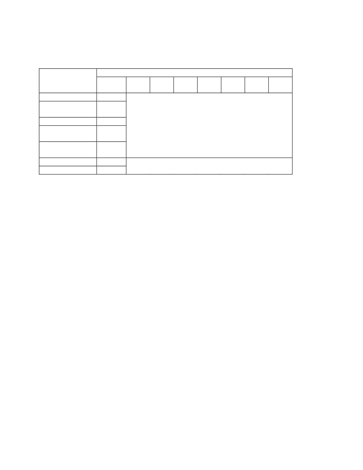
Table 1.2.2.g Minimum exterior distances (in meters) from a PES with ammunition of HD1.3G.
Quantity-Distances for HD1.3G
Exposed Site
Protection
500 kg
1 ton
5 ton
10 ton
15 ton
20 ton
25 ton
level
NEQ
NEQ
NEQ
NEQ
NEQ
NEQ
NEQ
Unprotected personnel
N/A*
51
64
110
140
160
175
190
Semi-protected
N/A*
No QD
No QD
No QD
No QD
No QD
No QD
No QD
personnel
Protected personnel
N/A*
No QD No QD No QD No QD No QD No QD No QD
Unprotected
POL-
D= 6.4 Q1/3
51
64
110
140
160
175
190
installation
Protected
POL-
D= 3.2 Q1/3
26
32
55
68
80
87
94
installation
Unprotected civilian
D= 6.4 Q1/3
51
64
110
140
160
175
190
Chemical industry
D= 6.4 Q1/3
51
64
110
140
160
175
190
*It is here assumed that there are opportunities to evacuate personnel after alarm.
4.2.4.3
Acceptable activities for 4,000 kg NEQ HD1.1
The statements in Table 1.3a apply under the precondition that by means of protective measures it has been
ensured that in the worst case a NEQ of 4,000 kg of HD1.1 may detonate at once in an ammunition container. It is
assumed that temporary structural protective measures, barricades or other barriers exist at the PES. The exposed
sites must be protected by protective roofs especially against fragments and projections. The distances in Table 1.3a
are laid down in such a way that the direct and indirect consequences of an occurrence of damage will not lead to a
catastrophe.
-IV-2-18-
Change 3

AASTP-1
(Edition 1)
Table 1.3.a Tolerable activities in case there is a small probability of an accidental explosion of
4,000 kg
NEQ of HD1.1.
Minimum
Tolerable activities
Risk level and
range (m)
expected
consequences in
case of an explosion
350
a)
Built-up area
b)
Minor risk
c)
Projections and
breaking glass
250
d)
Billets if structural
g)
Medium risk
protection is available
h)
Injuries caused
e)
Scattered buildings
by projections,
f)
Public roads
collapse and
breaking glass
150
i)
Billets if structural
l)
Significant risk
protection against
m)
Injuries caused
projections, breaking glass,
by fragments
and collapse is available
and projections
j)
Unprotected personnel in
n)
Fatalities
the open: 50 maximum,
temporarily
k)
Public roads: low density
100
o)
Personnel in the open with
s)
Significant risk
individual protective
t)
Injuries caused
equipment: 20 maximum,
by fragments
for a short time
and projections
p)
Continuous parking of
u)
Fatalities
armoured vehicles,
temporary parking of
vehicles
q)
Storage of materiel
r)
Maintenance work if
structural protection is
available
50
v)
Guard personnel: 10
y)
Significant risk
maximum, continuously
z)
Injuries caused
w)
Structural protection against
by blast,
projections and collapse
fragments and
x)
Parking of armoured
projections
vehicles for a short time
aa) Fatalities
< 50
bb) Ammunition handling: 2 to
cc) Significant risk
6 persons and vehicles for a
dd) Fatalities
short time
-IV-2-19-
Change 3
AASTP-1
(Edition 1)
4.2.4.4.
Consequence-analysis tools
a)
Hazard Diagrams
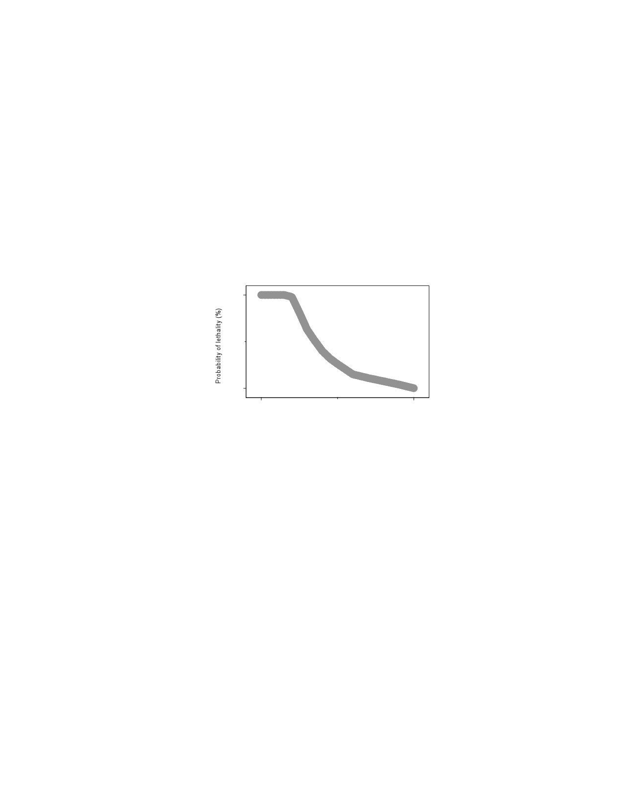
In practise, situations may arise in which the standard minimum quantity-distances can not be observed.
For some well-documented exposed sites, like unprotected humans and humans in buildings, the resulting
consequences are known. Figure 2.1.a shows a general hazard diagram in which the increase in risk as a
function of the actual distance between PES and ES is presented. The example curve represents the risk for
personnel in the open subjected to explosion effects of HD1.1 articles with a NEQ of about 5 tons.
The (upcoming) NATO publication AASTP-4 (Risk Manual) includes detailed information on risk
assessment and -analysis methodologies and tools. In the absence of AASTP-4, a useful methodology is
described in the following section.
100
0
0
500
Distance from PES (m)
Figure 2.1.a The increase of risk when advised minimum quantity-distances can not be met [7].
b)
Hazard Formula
In the following the concept of the hazard formula is shown by means of an example. It uses quantities,
which on the one hand are closely related to the hazardousness of an accidental detonation and on the other
hand can be analysed with a relatively high degree of exactness. The proposed procedure leads to a clear
result: It thus enables the responsible officer to take his stand against risky storage situations.
The scenario: an amm unition container containing a load quantity with an NEQ of 4,000 kilograms
is to be stored. The numerical data regarding the hazard potential and the reduction factors are to be taken
as examples. Should the proposed approach be taken into consideration, it will be the responsibility of
ammunition safety experts to determine the parameters of the hazard formula.
The hazard formula: For the "hazard G" for persons staying in the environment of a field storage site, a
"hazard potential P" is determined. The "reduction factors F" reduce the hazard potential.
G = P / (F1ςF2ςF3...)
-IV-2-20-
Change 3

AASTP-1
(Edition 1)
The hazard formula is structured in such a way that for a positive decision a value G equal to or smaller
than 1 is required.
The hazard potential: In order to obtain numerical values for the hazard potential P of an ammunition
container it is proposed that the hazard divisions and the compatibility groups available for all types of
ammunition be used. In accordance with the six hazard divisions, an exponential rise of hazard potential P
is allocated to the ammunition container. That means:
Hazard Division 1.6
Hazard Potential P = 2
Hazard Division 1.5
Hazard Potential P = 4
Hazard Division 1.4
Hazard Potential P = 8
Hazard Division 1.3
Hazard Potential P = 16
Hazard Division 1.2
Hazard Potential P = 32
Hazard Division 1.1
Hazard Potential P = 64
The reduction factors: In order to reduce the hazard G to the value 1 or smaller, reduction factors F are
used. For that purpose physical and organizational reduction factors are taken into consideration.
Physical reduction factors Fm:
As examples for physical reduction factors Fm for the ammunition container with NEQ = 4000 kilograms
the following factors are suggested:
•
Barricade in due form:
Fm1 = 4
•
Simple barrier:
Fm2 = 2
•
Making use of the terrain (under certain circumstances):
Fm3 = 2 through 4
•
Explosive quantity distance 500 m:
Fm4 = 16
•
Explosive quantity distance 350 m:
Fm5 = 8;
•
Explosive quantity distance 250 m:
Fm6 = 4
•
Explosive quantity distance 150 m:
Fm7 = 2;
•
Reduction of load quantity by 50 %:
Fm8 = 2
•
Demonstrated measures to avoid detonation transmission:
Fm9 = 2 through 16.
Organizational reduction factors Fo:
Hazard G can also be reduced by organizational measures. Periods in the endangered area can be limited in
regard to number of people present as well as to location and time. Examples:
1.
The distance range R < 150 meters must be crossed. By means of organizational measures it is
ensured that only one vehicle at a time stays in the area for a few seconds. Fo1 = 2.
2.
In the distance range R = 150 meters to R = 250 meters unprotected people stay for no longer
than a few hours for physical exercises. Fo2 = 4.
3.
The rooms of a building on the side facing the storage site are not occupied.
Fo3 = 2.
Under certain conditions a strict guard, an alarm system, or video monitoring may contribute to reduce the
hazard.
There may be cases in which the decision must be made that only one or two of the organizational
reduction factors may be used.
-IV-2-21-
Change 3

AASTP-1
(Edition 1)
Renunciation: Application of the hazard formula may mean renunciation. If it is impossible to achieve risk
value 1 by means of physical and organizational measures there remains the possibility to reduce the
quantity of ammunition stored or to do without certain ammunition types.
Step-by-step approach: The procedure is completed by a step-by-step approach:
1.
Operational pl anning: Storage of ammunition and explosives should be taken into
consideration when planning out-of-area missions. That planning is done at home by means of
ammunition catalogs, plane-table sheets, layout plan and so on. The result of the operational
planning is a hazard potential P and references to potential reduction factors. Operational
planning has to come to the result that it is possible to obtain the value G = 1 by means of the
hazard formula.
2.
Local planning: At the operational location the first task will be to define the reduction factors
F. Can the reduction factors proposed within the scope of operational planning be implemented?
Local planning directs the measures which enable achievement of the value G = 1 by means of
the hazard formula.
3.
Measures t aken on -site: The last decision level concerns the current situation on-site which
may constantly change during out-of-area missions. Does the hazard potential ascertained during
operational planning and local planning still apply? Are the reduction factors still valid? How
much ammunition has been added or taken away? Which changes have occurred in the
environment? Is equipment and materiel available by now to erect a larger barricade? Have there
been terrorist attacks? Has the situation changed in regard to sabotage? On site the measures
have to be taken which make it possible to obtain the value G = 1 by means of the hazard
formula.
Example: An ammunition container holds Q = 4000 kilograms of engineer demolitions of Hazard Division
1.1. According to operational planning it has a hazard potential with the value P = 64. At the operational
location a minimum explosive quantity distance of R = 350 meters can be observed - corresponding to
reduction factor Fm5 = 8. A barrier in due form reduces the hazard potential by a reduction factor Fm1 = 4. In
order to achieve the hazard value G = 1, an organisational measure must be taken. The rooms of the
barracks facing the storage site must not be occupied: Fo3 = 2. The hazard formula leads to the result:
G = P / (Fm5 ς Fm1 ς Fo3) = 64 / (8 ς 4 ς 2) = 1.
With the value G = 1 relative safety is achieved. In the case of an accident serious injuries and especially
fatalities should be avoided. A commander who gets the value G = 1 or lower three times - in other words:
who has come to a positive decision three times, may assume that he has done all that is humanly possible.
The remaining risk will be justifiable.
-IV-2-22-
Change 3

AASTP-1
(Edition 1)
Section V - Fire-Fighting
4.2.5.1.
General
Fire-fighting principles and procedures are the same as those given for permanent depots in Part I, Chapter
7 and Part II, Chapter 4 respectively. However, ammunition in field storage is more vulnerable to fire than when in
permanent depots, therefore more importance should be placed on fire precautions and fire-fighting in field storage.
4.2.5.2.
Symbols
Fire-fighting symbols must be displayed at each Field Storage Site. Symbols are fixed to posts, clear of the
ammunition and placed where they are easily seen by anyone approaching the site. To take into account the need for
camouflage as the situation may require, the colour of the fire symbols should be left to the discretion of the
National Authorities.
-IV-2-23-
Change 3

AASTP-1
(Edition 1)
CHAPTER 3 - QUANTITY-DISTANCE PRINCIPLES FOR MISSILE INSTALLATIONS
4.3.0.1.
General
The quantity-distance principles missile installations are essentially the same as those given in Part I,
Chapter 4 for aboveground storage of ammunition. These distances do not cater for the inadvertent release of a
missile. Each missile installation is treated as a PES requiring Interior and Exterior Quantity-Distances as given in
Part I, Annex A, Section II. Judgement should be used to associate the missile installation with an appropriate
pictograph for a PES taking account of the particular design. Reference to Part III, Chapter 2 may also be necessary.
Interior Quantity-Distances required for system-determined technical and/or operational reasons are not taken into
consideration in this chapter. They are part of the weapons system regulations.
4.3.0.2.
Potential Explosion Sites
a)
Launching platforms, warheading buildings, ready-round storage areas and other facilities where the
missile with warhead is serviced or stored are considered to be PES containing ammunition of Hazard
Division 1.1.
b)
The "Definitive Drawings" for a missile installation should include the separation distances necessary to
prevent propagation of explosion. Where operational requirements for the missile system necessitate
smaller distances, the PES are aggregated and considered to be one PES as regards Exterior Quantity-
Distances.
4.3.0.3.
Exposed Sites
a)
Military sites such as operation centres, readiness structures, radar and communication installations, fuel
stations, parking areas and guard shelters may be considered to be ES which are protected by appropriate
Interior Quantity-Distances. These ES may be inside the missile installation under consideration or inside
another military installation.
b)
The "Definitive Drawings" for a missile installation are based on operational requirements which may
override the Interior Quantity-Distances and which must be taken into account by additional infrastructure
measures (site safety plans).
c)
An Exposed Site outside a missile installation, not being inside another military installation, must be
protected by the Exterior Quantity-Distances given in Part I.
-IV-3-1
Change 3

AASTP-1
(Edition 1)
4.3.0.4.
Measuring of Quantity-Distances
Quantity-Distances at launcher platforms are measured from the extremities of the missile(s) when in
normal position on the platform. As regards assembly buildings and storage sites at a missile installation the normal
procedure in Part I, paragraph 1.3.2.3. applies.
4.3.0.5.
Net Explosives Quantity
The normal procedure for computing the NEQ applies, see Part I, subparagraphs 1.3.2.3.a) and 1.3.2.3.b).
Information, which may be classified, on the effective NEQ of a particular type of missile should be obtained from
the design authority. Otherwise the actual NEQ must be calculated in accordance with the definition as follows: The
NEQ is the total explosives content of ammunition unless it has been determined that the effective quantity is
significantly different from the actual quantity. It does not include such substances as white phosphorus, war gases
or smoke and incendiary compositions unless these substances contribute significantly to the dominant hazard of the
hazard division concerned.
-IV-3-2
Change 3

AASTP-1
(Edition 1)
CHAPTER 4
reserved
(Formerly “Quantity-Distance Principles For
Basic Load Ammunition Holding Areas”. This Chapter has been moved to AASTP-5.)
-IV-4-1-
Change 3

AASTP-1
(Edition 1)
CHAPTER 5 - QUANTITY-DISTANCE PRINCIPLES FOR
AIRFIELDS USED ONLY BY MILITARY AIRCRAFT
4.5.0.1.
General
a)
This chapter recommends principles and safety requirements for airfields used only by military aircraft.
b)
Air forces generally operate in war from the same locations that they occupy in peacetime. It may therefore
be necessary to store or hold weapons and ammunition as close to the aircraft as possible without exposing
personnel or facilities to unacceptable risk from an accidental explosion or the detonation of weapons or
ammunition as a result of enemy action in war. The following advice is intended to provide the minimum
levels of protection deemed necessary.
c)
The quantity-distances specified in this chapter apply essentially to PES which exist in peacetime. It
follows that Hardened Aircraft Shelters (HAS) which contain armed aircraft and/or stocks of ammunition
in peacetime should be treated as PES. Commanders will need to decide the quantity-distances to be
applied to sites which only become PES in emergencies or wartime and such distances will need to be
catered for in the airfields' peacetime layout. In reaching his decision the Commander should bear in mind
that a reduction in recommended quantity-distances to non-operationally essential facilities may result, in
the event of an explosion at the PES in increased damage and casualties, whilst a similar reduction to
operationally essential facilities could result in the facility ceasing to function and the prejudicing of
operational plans.
d)
Operational Commanders are advised that the more essential military resources may require additional
protection.
4.5.0.2.
Aircraft Parking - Designated Areas
a)
Aircraft carrying explosives must be armed, loaded, unloaded or parked in a Designated Area. Where
possible such a Designated Area should be separated from other such areas and from ES by the quantity-
distances given in paragraph 4.5.0.4.
-IV-5-1-
Change 3

AASTP-1
(Edition 1)
b)
A loading, unloading or parking area specifically designated for continual use presents a recurring hazard
as opposed to an occasional one and should be formally authorised for the purpose.
c)
Exception
This requirement does not apply to aircraft containing only installed explosives and safety devices such as
authorised signals in survival kits, egress systems components, engine starter cartridges, fire extinguisher
cartridges and other such items necessary to flight operations.
4.5.0.3.
Aircraft Parking - Principles for Selecting Designated Areas
a)
The following principles should be followed in selecting Designated Areas:
1.
The safest possible area compatible with quantity-distances prescribed in this chapter and
operational requirements must be used.
2.
The loading, unloading or parking area must be located outside runway clear zones. Aircraft
arm/disarm pads are exempted from the restriction1
3.
Whenever possible, the quantity-distances recommended in paragraph 4.5.0.4. should be observed
between adjacent loaded aircraft which are in the open. Where this is not possible consideration
should be given to grouping several aircraft together and separating the groups by greater
distances than can be provided between individual aircraft. If an explosion should occur, aircraft
in adjacent groups may be damaged by fragments; however, the explosion is unlikely to propagate
simultaneously. Subsequent explosions may be caused by fragments, debris or secondary fires.
1
In general, the applicable runway clearance is the 150 m lateral safety zone each side from the runway centreline. Further details
are given in the 6th or latest Edition of NATO Airfield Criteria.
-IV-5-2-
Change 3

AASTP-1
(Edition 1)
4.
Ideally, aircraft should face the direction involving least exposure of personnel, equipment and
facilities to the line of fire of forward-firing armament. For practical purposes, aircraft should be
pointed so that no centre of population exists for 3 000 m within 5° on either side of the line of
fire unless this is intercepted by a suitable barricade.
b)
Exceptions
Aircraft carrying their operational loads of gun ammunition, practice bombs and small rockets (e.g. 2.75"
HE rockets or others with equivalent characteristics) do not require the quantity-distances specified in
paragraph 4.5.0.4.
4.5.0.4.
Quantity-Distances
a)
The following quantity-distances, which assume Hazard Division 1.1 loads, may be used for all hazard
divisions. Where Part I of the Manual permits, lesser distances may be used for hazard divisions other than
Hazard Division 1.1.
b)
Quantity-Distances between Aircraft Loaded with Explosives
1.
Unbarricaded individual aircraft, or groups of aircraft at Designated Areas, loaded with explosives
should be separated from one another by AD13-distances (12.0 Q1/3) unless space limitations or
operational considerations dictate otherwise. At this distance, adjacent unsheltered aircraft may
sustain damage due to fragments but should, in most cases, remain operable. Where nearly
complete protection against fragments is deemed necessary, a distance of 270 m between aircraft
should be provided. Individual or groups of aircraft should be separated by AD10-distances (7.2
Q1/3) to protect against propagation of detonation. If the aircraft carry ammunition of comparable
resistance to propagation as robust shells, AD9-distances (4.4 Q1/3) may be used to protect against
simultaneous detonation. Lesser distances may be used for specific weapons where trials have
shown that such distances are adequate to minimize the probability of propagation.
-IV-5-3-
Change 3

AASTP-1
(Edition 1)
2.
Barricades between adjacent aircraft will prevent simultaneous propagation due to high velocity,
low angle fragments. It should be noted, however, that a barricade does not necessarily prevent
subsequent propagation or damage caused by blast, lobbed items, debris or secondary fires.
c)
Exterior Quantity-Distances from Designated Areas
Where possible, the appropriate Exterior Quantity-Distances in Part I should apply between parked aircraft
loaded with explosives at Designated Areas and ES not related to the servicing and support of those
aircraft. Safety is enhanced by towing aircraft, after loading, to a safer area rather than close to other
aircraft being loaded or unloaded.
d)
Quantity-Distances between HAS and Associated Storage Facilities
1.
HAS2 and associated storage facilities spaced according to Table 5-II will prevent propagation
between such facilities. An explosion in one shelter or ready storage facility may destroy it and its
contents, but aircraft within adjacent shelters will be undamaged, provided the doors are closed.
Those aircraft may not be immediately removable due to debris.
2.
HAS and associated storage facilities spaced according to Table 5-III may be damaged; however,
there will be a high degree of protection against propagation. These distances should be used only
in wartime or during periods of increased operational readiness.
3.
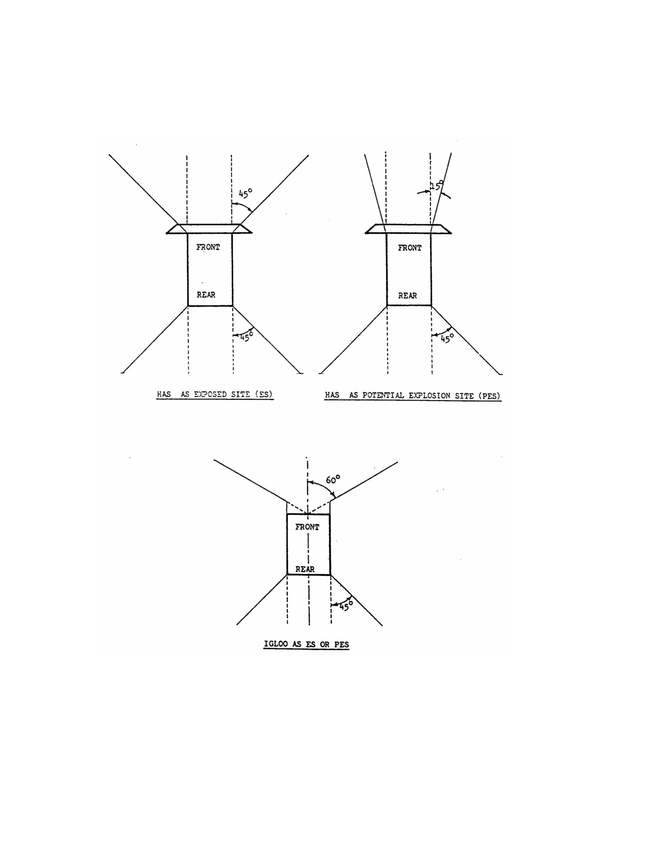
Areas of hazard to front, side or rear of HAS or igloos as PES or ES lie in the arcs shown in
Figure 5-I. A particular face of an ES is deemed to be threatened by a PES face when both these
faces lie within the arc of threat or hazard of the other. In those cases where an ES lies on the line
separating rear/side etc. of a PES, the appropriate larger quantity-distance should be observed.
2
The tables in this chapter do not apply to Norwegian designs of third generation HAS for which tables will be published in due course.
-IV-5-4-
Change 3

AASTP-1
(Edition 1)
e)
Quantity-Distances to Runways and Taxiways
If the transient risk to military aircraft movements is accepted, it is recommended that the separation of the
PES from runways and taxiways which are considered to be operationally essential should ideally be such
as to prevent the runways or taxiways being rendered unoperational by ground shock as a result of an
explosion in the PES. The use of a distance equivalent to about three times the crater radius is
recommended. In normal soil AD4-distances (1.8 Q1/3) should be used; in saturated soils or clay greater
distances may be advisable because of the increased crater radius. If the transient risk is not accepted,
AD13-distances (12.0 Q1/3) should be used to provide protection to the aircraft.
f)
Quantity-Distances to Explosives Workshops
Explosives workshops should be separated from other PES by AD11-distances (8.0 Q1/3). Suitably
hardened explosives workshops may be sited at reduced distances.
g)
Quantity-Distances to Facilities and Activities in Both Direct and Indirect Support of Flightline and
Aircraft Servicing
Use AD10-distances (7.2Q 1/3) for separation of any PES where explosives are present on a long-term basis
from squadron operations buildings, flightline maintenance functions, flightline fire and rescue stations,
and other activities in direct support of flightline and aircraft servicing (e.g. alert crew, POL and LOX
facilities) unless the facilities are hardened to NATO criteria, when reduced distances may be used. At this
distance, damage to unstrengthened buildings may be of a serious nature with resulting casualties. Where
greater protection is required, AD12-Distances
(9.6 Q1/3) should be used, except where
subparagraph 4.5.0.4.k) permits smaller distances. Use AD14-distances (16.0 Q1/3) for similar unhardened
facilities in indirect support of flightline operations, with reductions for facilities hardened to NATO
criteria. In transition to war (TTW) and war, all facilities may be considered to be directly supporting and
the lesser distances used.
-IV-5-5-
Change 3

AASTP-1
(Edition 1)
h)
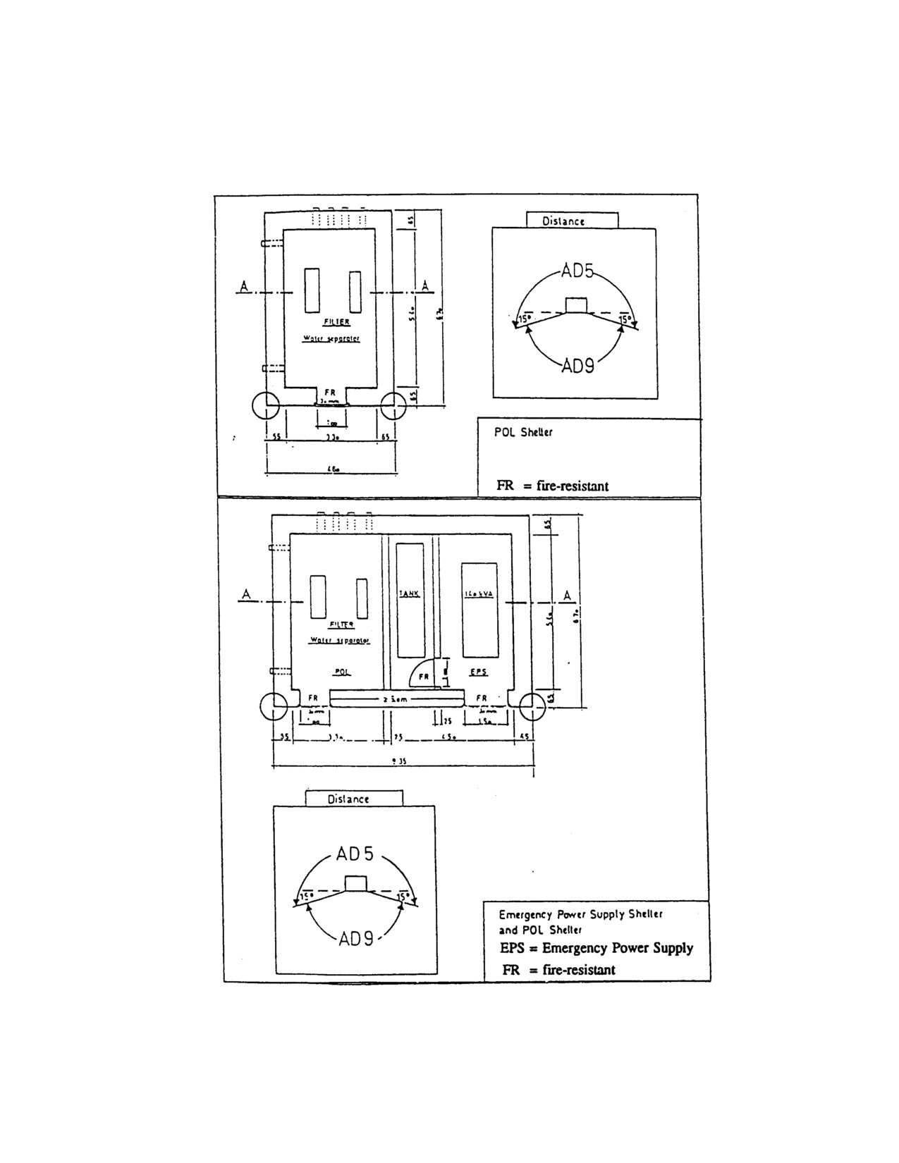
Quantity-Distances for Emergency Power Supply Shelter and POL Shelter for the Support of Hardened
Aircraft Shelters
If the quantity-distances prescribed in subparagraph 4.5.0.4.g) cannot be maintained, lesser quantity-
distances are permissible for the construction of Emergency Power Supply Shelter and POL Shelter for the
support of a nearby HAS under the following conditions:
1.
Power Supply and POL Shelters must be hardened
- Wall and roof thickness
: at least 65 cm reinforced concrete
- Gate thickness
: at least 30 mm steel plate
2.
The POL tank for this structure must be buried (minimum earth-cover 1 m).
3.
The following quantity-distances to PES have to be maintained (see Figure -II):
- Minimum distance between the walls and PES : AD5-distances
- Minimum distance between the gates and PES : AD9-distances, at least 25 m
- At least 25 m for the buried POL tank.
i)
Quantity-Distances to Military Aircraft not Loaded with Explosives
Use AD13-distances (12.0 Q1/3) for separation of PES from military aircraft in exposed parking (tankers,
transports), but damage may be sustained due to fragments (see sub-subparagraph 4.5.0.4.b).1.). Where
operational requirements outweigh consideration of asset preservation, distances may be reduced to that
dictated by operational necessity but minimum distances corresponding to the distance function 9.6 Q1/3 for
embarking/disembarking military personnel for transport and distances corresponding to the distance
function 7.2 Q1/3 for tanker aircraft should be considered.
j)
Quantity-Distances to Open Stacks of Ammunition
Open storage of ammunition, barricaded effectively, is permitted at not less than AD13-distances (12.0
Q1/3) from parked aircraft outside shelters.
-IV-5-6-
Change 3

AASTP-1
(Edition 1)
k)
Quantity-Distances to General Public and Central Airfield Administrative Support Facilities
1.
Use AD16-distances (14.0 Q1/3) from the rear and AD17-distances (18.0 Q1/3) from the sides and
front of ready service igloos containing up to 10 000 kg NEQ at loading density of up to 20 kg/m3.
Apply a minimum distance of 270 m to central airfield administrative support facilities and low
density public traffic routes.
2.
When the PES is a US third-generation or similar hardened aircraft shelter containing up to 5 000
kg NEQ, the AD18-distances (20.0 Q1/3) from the front, the AD19-distances (25.0 Q1/3) from the
side and AD14-distances (16.0 Q1/3) from the rear may be used to protect an unhardened ES
against debris and blast. With NEQ of 50 kg or less in a HAS, a minimum distance of 80 m to the
front of the HAS and nil to the side and rear need only to be applied.
3.
Use AD15-distances (22.2 Q1/3) for other PES where explosives are present on a long-term basis,
and apply minimum distances of 270 or 400 m depending on the nature of the PES (open vs igloo)
and the ES (density of population).
4.
Where ES have been hardened, lesser distances may be used depending on the degree of
hardening provided.
4.5.0.5.
Operational Considerations
a)
When operational requirements necessitate the use of Table 5-III or distances less than those prescribed
above, particularly in the case of explosives of Hazard Division 1.1, the operational Commander should be
advised of any potentially serious risks in accordance with Part I, Chapter 3, Section VII, so that measures
can be taken to eliminate or at least reduce the consequences.
b)
The aim should be to maintain the maximum practicable separation between unbarricaded aircraft loaded
with explosives of Hazard Division 1.1. The use of distances less than 270 m involves a progressively
increasing risk of propagation by blast, flame, radiant heat and projections.
c)
Safety is enhanced by towing aircraft, after loading, to aircraft being loaded or unloaded.
-IV-5-7-
Change 3
AASTP-1
(Edition 1)
Figure 5-I
-IV-5-8-
Change 3
AASTP-1
(Edition 1)
FIGURE 5-II
-IV-5-9-
Change 3
AASTP-1
(Edition 1)
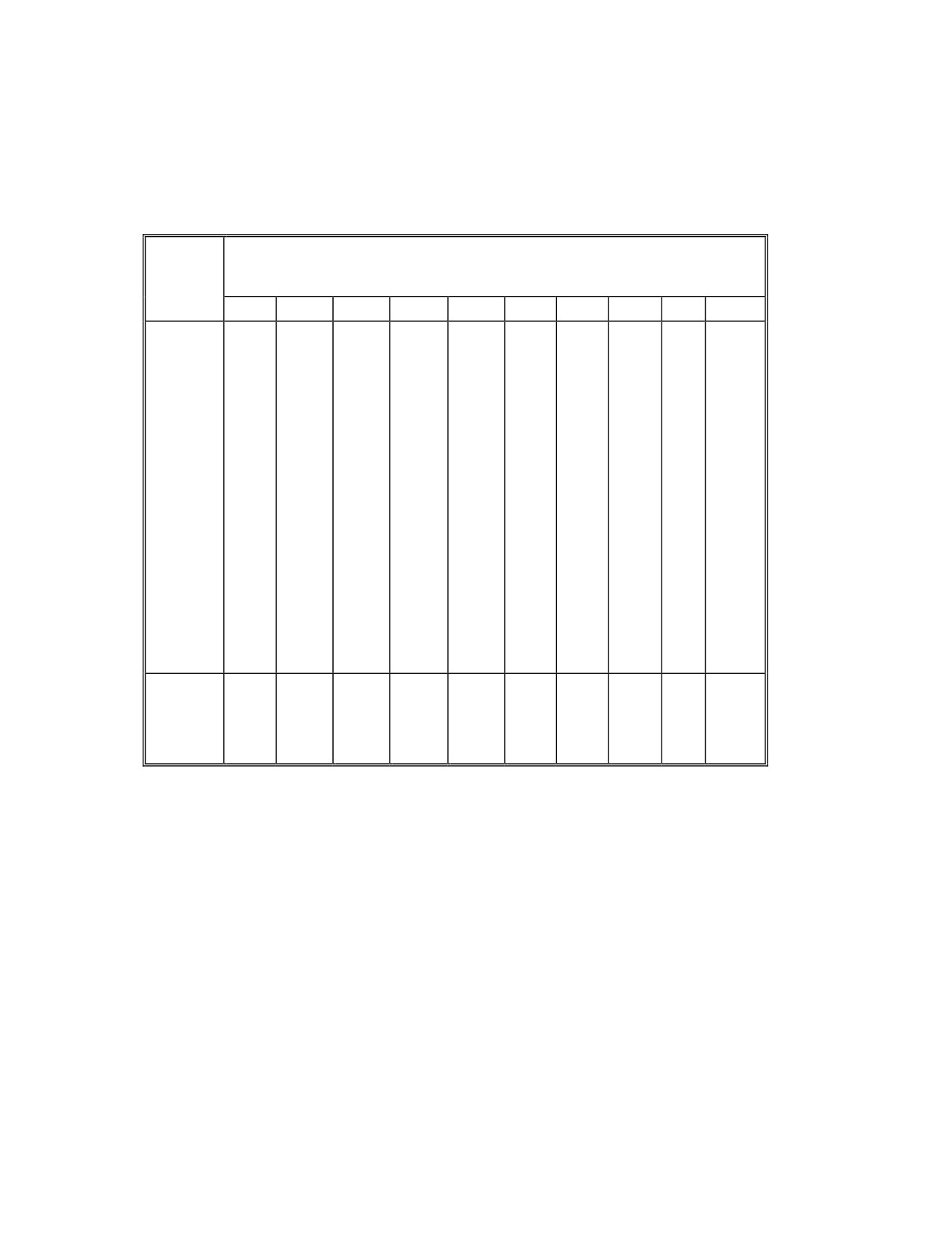
TABLE 5-I (PAGE 1)
Q-D TABLE FOR AIRFIELDS HAZARD DIVISION 1.1
NEQ
Quantity-Distances
Q
m
kg
AD1
AD2
AD3
AD4
AD5
AD6
AD7
AD8
AD9
AD10
500
4
6
9
15
16
20
25
29
35
58
600
5
7
10
16
17
21
27
31
38
61
700
5
7
10
16
18
22
28
32
40
64
800
5
7
11
17
19
23
30
34
41
67
900
5
8
11
18
19
24
31
35
43
70
1 000
5
8
11
18
20
24
32
36
44
72
1 200
6
9
12
20
21
26
34
39
47
77
1 400
6
9
13
21
22
27
36
41
50
81
1 600
6
9
13
22
23
29
37
43
52
85
1 800
7
10
14
22
24
30
39
44
54
88
2 000
7
10
14
23
25
31
40
46
56
91
2 200
7
10
14
24
26
31
42
47
57
94
2 500
7
11
15
25
27
33
43
49
60
98
3 000
8
12
16
26
29
35
46
52
64
105
3 500
8
12
17
28
30
37
49
55
67
110
4 000
8
13
18
29
32
39
51
58
70
115
4 400
8
13
18
30
33
39
52
59
72
120
5 000
9
14
19
31
34
42
55
62
76
125
6 000
10
15
20
33
36
44
58
66
80
135
7 000
10
15
22
35
38
46
61
69
85
140
8 000
10
16
22
36
40
48
64
72
88
145
8 800
10
17
23
37
41
50
66
74
91
150
9 000
11
17
23
38
42
50
67
75
92
150
10 000
11
17
24
39
43
52
69
78
95
160
Distance
AD1
AD2
AD3
AD4
AD5
AD6
AD7
AD8
AD9
AD10
Functions
=
=
=
=
=
=
=
=
=
=
0.5
0.8
1.1
1.8
2.0
2.4
3.2
3.6
4.4
7.2
Q1/3
Q1/3
Q1/3
Q1/3
Q1/3
Q1/3
Q1/3
Q1/3
Q1/3
Q1/3
-IV-5-10-
Change 3
AASTP-1
(Edition 1)
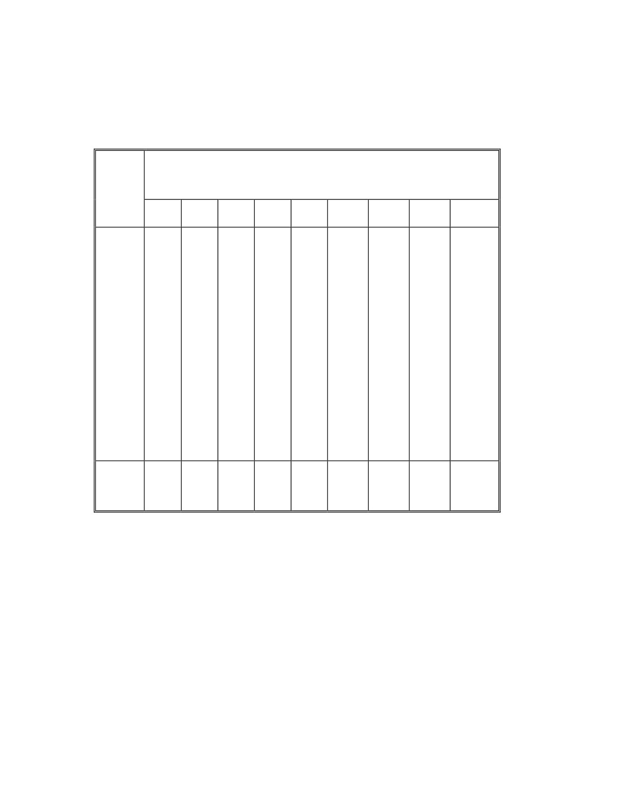
TABLE 5-I (PAGE 2)
Q-D TABLE FOR AIRFIELDS HAZARD DIVISION 1.1
NEQ
Quantity-Distances
Q
m
kg
AD
AD1
AD1
AD1
AD1
AD15
AD17
AD18
AD19
11
2
3
4
5
a)
a)
a)
a)
500
64
77
95
130
270
270
270
160
200
600
68
81
100
135
|
|
|
170
215
700
72
86
105
145
|
|
|
180
225
800
75
90
110
150
|
|
|
190
235
900
78
93
115
155
|
|
|
195
245
|
|
|
1 000
80
96
120
160
|
|
|
200
250
1 200
86
105
130
175
|
|
|
215
270
1 400
90
110
135
180
|
|
|
225
280
1 600
94
115
140
190
|
|
|
235
295
1 800
99
120
145
195
|
|
|
245
305
|
|
|
2 000
105
125
150
205
|
|
|
255
315
2 200
105
125
155
210
270
|
|
265
330
2 500
110
135
165
220
275
|
|
275
340
3 000
120
140
175
235
305
|
270
290
365
3 500
125
150
180
245
330
|
275
305
380
|
4 000
130
155
190
255
350
|
290
320
400
4 400
135
160
200
260
365
|
295
330
410
5 000
140
165
205
275
380
|
310
345
430
6 000
150
175
220
295
405
|
330
--------
---------
7 000
155
185
230
310
425
270
345
8 000
160
195
240
320
445
280
360
8 800
170
200
250
330
460
290
375
9 000
170
200
250
335
465
295
380
10 000
175
210
260
345
480
305
390
Distance
AD11
AD12
AD13
AD14
*)
AD16
AD17
AD18
AD19
Functions
=
=
=
=
=
=
=
=
9.6
12.0
16.0
**)
14.0
18.0
20.0
25.0
3
Q1/
Q1/3
Q1/3
Q1/3
Q1/3
Q1/3
Q1/3
Q1/3
*)
AD15 = 5.5 Q1/2 for Q < 4 500 kg
**)
AD15 = 22.2 Q1/3 for Q
4 500 kg
NOTE: a)
see subparagraph 4.5.0.4.k)
-IV-5-11-
Change 3

AASTP-1
(Edition 1)
TABLE 5-II (PAGE 1)
ASSET PRESERVATION
FROM
1st Generation
2nd and 3rd Generation
(PES)
Aircraft Shelter a)
Aircraft Shelter a)
TO (ES)
Side
Rear
Front
Side
Rear
Front
1st Generation
Side
AD8
AD6
AD8
AD8
AD6
AD8
Aircraft
Rear
AD7
AD5
AD7
AD7
AD5
AD7
Shelter
Front
AD10
AD10
AD10
AD10
AD10
AD10
2nd or 3rd Generation
Side
AD8
AD6
AD8
AD8
AD6
AD8
Aircraft
Rear
AD7
AD5
AD7
AD7
AD5
AD7
Shelter
Front
AD9
AD8
AD10
AD9
AD8
AD10
Distance Functions:
see TABLE 5-I
NOTE: a)
Limited to a maximum of 5 000 kg per shelter.
-IV-5-12-
Change 3

AASTP-1
(Edition 1)
TABLE 5-II (PAGE 2)
ASSET PRESERVATION
FROM (PES)
Ready Service
Ready Service
Igloo b)
Magazine c)
TO (ES)
Side
Rear
Front
Front
Barr.
Unbarr.
Barr.
Unbarr.
1st Generation
Side
AD3
AD3
AD7
AD7
AD7
AD7
Aircraft
Rear
AD3
AD3
AD7
AD7
AD7
AD7
Shelter
Front
AD9
AD8
AD10
AD10
AD10
AD10
2nd or 3rd
Side
AD3
AD3
AD7
AD7
AD7
AD7
Generation
Rear
AD3
AD3
AD7
AD7
AD7
AD7
Aircraft
Front
AD3
AD3
AD7
AD7
AD7
AD7
Shelter
Distance Functions:
see TABLE 5-I
NOTES:
b)
Ready Service Igloo - An earth-covered explosives storage location, often utilizing an arch-type interior
shell, used to store built-up ammunition for combat aircraft loading. Storage is limited to not more
than 10 000 kg NEQ and a loading density of not more than 20 kg m-1/3.
c)
Ready Service Magazine - Any aboveground explosives storage facility, other than an igloo, used to store
built-up ammunition for combat aircraft loading. Storage is limited to not more than 10 000 kg.
-IV-5-13-
Change 3

AASTP-1
(Edition 1)
TABLE 5-II (PAGE 3)
ASSET PRESERVATION
FROM (PES)
Igloo
Magazine
TO (ES)
Side
Rear
Front
Front
Barr.
Unbarr.
Barr.
Unbarr.
1st Generation
Side
AD5
AD5
AD7
AD7
AD7
AD7
Aircraft
Rear
AD5
AD5
AD7
AD7
AD7
AD7
Shelter
Front
AD10
AD10
AD10
AD10
AD10
AD10
2nd or 3rd
Side
AD5
AD5
AD7
AD7
AD7
AD7
Generation
Rear
AD5
AD5
AD7
AD7
AD7
AD7
Aircraft
Front
AD5
AD5
AD7
AD7
AD7
AD7
Shelter
Distance Functions:
see TABLE 5-I
-IV-5-14-
Change 3

AASTP-1
(Edition 1)
TABLE 5-III (PAGE 1)
PROPAGATION PREVENTION
FROM (PES)
1st Generation
2nd or 3rd Generation
Aircraft Shelter
Aircraft Shelter a)
TO (ES)
Side
Rear
Front
Side
Rear
Front
1st Generation
Side
AD2
AD2
AD3
AD2
AD2
AD3
Aircraft
Rear
AD2
AD2
AD3
AD2
AD2
AD3
Shelter
Front
AD6
AD4
AD7
AD6
AD4
AD8
2nd or 3rd Gene-
Side
AD2
AD2
AD3
AD2
AD2
AD3
ration Aircraft
Rear
AD2
AD2
AD3
AD2
AD2
AD3
Shelter
Front
AD4
AD3
AD5
AD4
AD4
AD6
Ready
Side
AD2
AD2
AD3
AD2
AD2
AD3
Service
Rear
AD2
AD2
AD3
AD2
AD2
AD3
Igloo
Front
AD3
AD3
AD5
AD3
AD3
AD6
Barr.
Front
AD6
AD4
AD7
AD6
AD4
AD8
Unbarr.
Ready Ser-
Barr.
AD6b)
AD6b)
AD6
AD6b)
AD6b)
AD6
vice Maga-
Unbarr.
AD9
AD9
AD9
AD9
AD9
AD9
zine
Distance Functions:
see TABLE 5-I
NOTES:
a)
Limited to a maximum of 5 000 kg per shelter.
b)
This separation provides a high degree of protection (see Part I, subpara. 1.3.1.9.b)2)). AD3-distances may
be used for robust stores or in wartime or emergency situations and would provide a moderate degree
of protection (see Part I, subpara. 1.3.1.9.b)3)).
-IV-5-15-
Change 3