MANUAL OF NATO SAFETY PRINCIPLES FOR THE STORAGE OF MILITARY AMMUNITION AND EXPLOSIVES (May 2010) - page 10

AASTP-1
(Edition 1)
Section III - Airblast
2.5.2.1
Introduction
General
Airblast parameters have been thoroughly investigated in the course of data collections carried out for
weapons effects analyses. Open air and open surface detonations have been the subject of complex
experiments and scientific research providing the data basis to determine the relevant airblast loads.
Furthermore, a lot of experimental data and experiences from explosions are available covering the airblast
loads occurring after accidental explosions in ammunition storage facilities. The scientific evaluation of these
data as well will provide the necessary design basis.
Intensity, waveform and interaction of an airblast with persons, structures and equipment items are important
factors in establishing the quantity distances for ammunition and explosives, especially such of hazard division
1.1.
In case standard quantity distance tables are not applied (or cannot be applied), potential explosion sites and
exposed structures must be designed and calculated individually. Under certain circumstances, this procedure
may lead to considerable cost savings in the design of ammunition storage facilities, e.g. in terms of material
and land requirements.
Problem Description
The airblast load due to an explosion may be readily simplified for design purposes. It is characterized by a
relatively flat blast wave, whose peak overpressure and variation with time essentially are functions of distance
and charge, and the dynamic pressure variation with time. It must be noted that deviations from the model
explosion environment will change the airblast parameters.
Assumptions and Definitions
Design and calculation methods for ammunition storage facilities are mainly based on modeling and practice-
oriented assumptions.
In general, the following assumptions are introduced in order to simplify calculation of airblast loads and
reduce input data.
(1)
Charge Shape
The charge is assumed to be hemispherical and placed directly on the ground at sea level.
Note:
Other charge shapes and positions cause asymmetrical propagation of blast and, in part, considerable
deviations of blast parameters.
(-->> Ref [3], [45], [52], [53], [62], [66])
(2)
Reference Explosion
The reference explosion is taken to be the high order detonation of an exposed bare charge of TNT. In case of
explosives other than TNT or different explosion environments, the TNT equivalent mass must be
calculated using a conversion factor.
-II-5-14-
Change 3

AASTP-1
(Edition 1)
Note:
The TNT equivalent factor is not a constant value. Usually, a practicable value is used.
(-->> Table [5-2])
(-->> Ref [1], [3], [4], [55])
(3)
Blast Attenuation by Donor Structure
The attenuation due to the external walls or the earth cover can be taken into account as follows:
-
Proceeding from the basic assumption that a hemispherical charge explodes on the ground in
the open, an empirical attenuation factor is introduced to extrapolate a fictitious explosives
quantity inside the storage building.
-
The maximum permissible explosives quantity for the storage building is determined using
empirically developed and up dated regression equations for particular building types.
-
The airblast loads are determined using empirically developed formulations.
Note:
All methods are based on empirical data.
(-->> Ref [65], [76], [87], [88], [101], [127], [133])
(4)
Terrain and Vegetation
-
All assumptions relate to flat terrain without obstacles and vegetation.
-
Rising slops cause an increase of pressure.
-
Falling slopes cause a decrease of pressure.
-
A narrow valley with steep sides causes concentrated directional blast.
-
Significant vegetation, such as wood with a tree top height of more than 3.5 m, consumes
blast energy.
Properties of an Airblast Wave
An airblast wave due to an explosion consists of an incident blast wave and a dynamic blast wave.
(-->> Figure [5-1])
The incident peak overpressure is significantly higher than the dynamic peak overpressure.
For design purposes, the duration of the incident blast wave and the dynamic blast wave may be taken to be
equal although the pressure drops behind the respective shock fronts differ considerably and the dynamic
pressure normally takes longer to decrease to the ambient pressure level. The pressure drop of the incident
blast wave is much steeper.
The negative overpressure phase (suction phase) may be neglected for design purposes.
2.5.2.2
Physical Relations Between Airblast Parameters
The characteristic parameters of a blast wave with a sudden pressure discontinuity at the shock front are as
follows:
-
Overpressure;
-
Dynamic pressure
-
Reflected pressure;
-
Density;
-
Shock front velocity;
-
Particle velocity.
-II-5-15-
Change 3

AASTP-1
(Edition 1)
These parameters are derived using the Rankine-Hugoniot equations. When one of the shock front parameters of the
incident blast wave has been determined as a function of the scaled distance, the other parameters can be calculated
using the Rankine-Hugoniot equations and a simple integration procedure. The Rankine-Hugoniot equations are based
on the principles of conservation of mass, energy and momentum.
(-->> Ref [3], [72])
Restrictions:
-
The Rankine-Hugoniot equations are only applicable under the condition that the particle
velocity ahead of the shock front is zero ( uo = 0 ) and that the air behaves like an ideal gas with a specific heat ratio of τ
= 1.4.
-
It is further assumed that there is one single shock front caused by a surface explosion of a
hemispherical shaped charge.
Rankine-Hugoniot equations
(1)
Shock front velocity U
1/2
ň
ʼn
6 · Pso
U = ao ·
Ň
1 +
Ň
eq [5-01]
7 · Pa
Ŋ
ŋ
(2)
Particle velocity u
5 · Pso
ao
u =
·
7 · Pa
(1 + 6 · Pso / 7 · Pa)1/2
eq [5-02]
(3)
Air density behind the shock front rho
7 + 6Pso/Pa
Rho =
· rho,a
7 + Pso/P
a
eq [5-03]
(4)
Dynamic pressure qo
qo = 0.5 · rho · u2
eq [5-04]
ň
ʼn
5
Pso2
qo =
Ň
Ň
2
7 · Pa + Pso
Ŋ
ŋ
eq [5-05]
(5)
Normally reflected pressure Pr
ň
ʼn
7 · Pa + 4 · Pso
Pr = 2 · Pso ·
Ň
Ň
7 · Pa + Pso
eq [5-06]
Ŋ
ŋ
For an ideal gas ( τ = 1.4 ) and high shock front pressure Pso, Pr approaches the limit 8·Pso.
For air, this limit can be exceeded. For low shock front pressures, the reflection factor
approaches the value of 2.
(Detailed formulations: -->> Ref [1], [3], [102])
(6)
Pressure-Time Variations of Incident Airblast and Dynamic Pressure
The time-dependent variation of the incident (side-on) pressure Ps(t), and the dynamic pressure q(t)
may be realistically represented using the modified Friedländer equation:
(-->> Ref [3])
t
-II-5-16-
Change 3

AASTP-1
(Edition 1)
t
Ps(t) = Pso · (1 -
) · e(-β·t/to)
0 ≤ t ≤ to
eq [5-07]
to
t
q(t) = qo · (1 -
) · e(-β·t/to)
0 ≤ t ≤ to
eq [5-08]
t
o
(Empirical values for β are given in Table [5-3])
(7)
Positive Impulse
The decisive parameter for the damage caused by airblast is the positive overpressure impulse. It
may be determined by integration of the positive overpressure phase, i.e. it is defined by the total
area below the pressure-time curve.
t
General impulse equation:
is =
Ps(t) · dt
o
Pso · to
I
s =
· ( 1 -
1 - e-β
)
β
β
eq [5-09]
ň
ʼn
qo · to
2
1
2
1 -
· (1 -
) -
· e-β
Iq =
Ň
Ň
β
β
β
β2
Ŋ
ŋ
eq [5-10]
Scaling Laws
(1)
General
The conversion of airblast parameters, distances and explosive charge masses from parameters of a
known explosion environment may be accomplished using scaling laws.
(2)
Cube-Root Law
Theoretically, the relation between distance, pressure, and explosive charge mass may be expressed
by a cube-root law. Full scale tests have shown that this proportionality between distance and charge
mass applies to quantities up to the megaton range.
(3)
Scaling
-
Distance - Charge Mass
1/3
Rx
ň
Qx
ʼn
=
Ň
Ň
eq [5-11]
Ro
Qo
Ŋ
ŋ
1/3
ň
Qx
ʼn
Rx = Ro ·
Ň
Ň
Qo
Ŋ
ŋ
eq [5-12]
-II-5-17-
Change 3

D
AASTP-1
(Edition 1)
-
Dynamic impulse:
Time - Charge Mass:
1/3
Rx
ň
Qx
ʼn
tx = to ·
= to ·
Ro
Ň
Qo
Ň
Ŋ
ŋ
eq [5-13]
Impulse - Charge Mass:
ň
ʼn
1/3
Rx
Qx
Ix = Io ·
= Io ·
Ň
Ň
Ro
Q
o
Ŋ
ŋ
eq [5-14]
Airblast parameters measure for different charge masses and at different atmospheric conditions
may be converted to standard conditions applying the Hopkinson-Cranz cube-root law and the Sachs
scaling laws. The latter is only applicable to ideal gases, i.e. it is not suited for air and high shock
front pressures.
-
Scale Factors …
… for Pressure P
ň
ʼn
Pa
eq [5-15]
SP =
Ň
Ň
Pa,s
Ŋ
ŋ
… for distance R
eq [5-16]
… for time t
eq [5-17]
… for impulse I
eq [5-18]
--> Index Xa,s …. standard conditions at sea level
-II-5-18-
Change 3

AASTP-1
(Edition 1)
(4)
TNT equivalent
For determining the characteristic airblast parameters, it is advisable to convert the actual charge
mass to the equivalent TNT charge mass in order to make use of the various existing design
diagrams which are usually related to TNT. For design purposes, the values given in Table [5-2]
may be used.
The majority of measurements of airblast parameters so far has been carried out using pure TNT charges. For
calculations related to other explosives with or without confinement and different explosion
environments, it is advisable to use the respective TNT equivalents for these conditions. These
equivalents are individually determined with respect to pressure and impulse by means of tests or
defined using the specific detonation energy of the explosive.
ň
ʼn
Ed
exp
QTNT,e = Ň
Ň · Q
exp
Ed
TNT
Ŋ
ŋ
eq [5-19]
QTNT,e (kg)
equivalent TNT charge mass
Qexp (kg)
actual explosive charge mass
EdTNT (J/kg)
specific detonation energy of TNT
Edexp (J/kg)
specific detonation energy of the actual explosive
2.5.2.3
Determination of Characteristic Airblast Parameters for Surface Detonations
of
Hemispherical
Explosive Charges in the Open
Characteristic Airblast Parameters
-
Peak side-on overpressure
Pso
MPa
-
Dynamic overpressure
qo
MPa
-
reflected overpressure
Pr
MPa
-
Scaled positive side-on impulse
is
MPa-ms/(kg)1/3
-
Scaled positive reflected impulse
ir
MPa-ms/(kg)1/3
-
Positive airblast duration
to
s
-
Arrival time
ta
s
-
Shock front velocity
U
m/s
-
Particle velocity behind shock front
u
m/s
Note:
The scaled parameters must be multiplied by the cube root of the TNT equivalent mass.
Design Fundamentals
(1)
Design Diagrams
For design and damage assessment purposes, the characteristic airblast parameters may be
determined from Figure
[5-2a] and
[5-2b] taking into account the assumptions previously
established. The diagrams are based on numerous tests and apply to charge masses from 1 kg up to
400 000 kg.
(-->> Ref [5])
-II-5-19-
Change 3

AASTP-1
(Edition 1)
The curves shown in Figure [5-2a] and [5-2b] may be programmed as polynomial equations on a
personal computer. The respective data are summarized in Table [5-5].
(additional information: -->> Ref [3])
(2)
Common Formulas
The formulations described in Table [5-5] are not suited to be used with pocket calculators.
Therefore, the following formulas are recommended for quick calculations
with
acceptable
accuracy.
(-->> Ref [133 revised]) …
Explosive
:
TNT, TNT - equivalent
Type of detonation
:
surface detonation
Place of detonation
:
in the open
Scaled distance
:
z = R / (Q)1/3 (m / (kg)1/3)
Charge mass
:
Q
(kg)
Distance
:
R
(m)
-
Peak Side-On Overpressure Pso (MPa)
Range
Function
0.50 ≤ Z < 0.75
Pso = 1.313137 . Z(-1.910441)
0.75 ≤ Z < 3.50
Pso = 1.330026 . Z(-2.218832)
3.50 ≤ Z < 8.50
Pso = 0.724571 . Z(-1.726565)
Pso = 0.293592 . Z(-1.295654)
8.50 ≤ Z < 30.00
-
Scaled Side-on Impulse is (MPa-ms/(kg1/3))
Range
Function
0.50 ≤ Z < 1.0
is =
-
41.2564 · Z5 + 144.608 · Z4
- 198.8880 · Z3 + 134.238 · Z2
-
44.3554 · Z + 5.8956
1.0 ≤ Z ≤ 30.0
is =
- 0.254674 · Z(-0.918606)
-
Positive Pressure Duration To (ms)
ň
ʼn
Linear pressure waveform:
2 · Is
To =
Ň
Ň
Pso
Ŋ
ŋ
eq [5-20]
Is = is · NEQ(1/3)
eq [5-21]
Exponential Pressure Waveform:
-->> Figure [5-2a], [5-2b]
-
Pressure Drop Constant β
The pressure drop constant β is determined by iteration of the following equation:
Pso · to
β2
=
Is
β - (1 - e(-β))
eq [5-22]
-II-5-20-
Change 3

AASTP-1
(Edition 1)
2.5.2.4
Determination of Characteristic Airblast Loads due to an Explosion Event in an Ammunition
Storage Facility
Earth-Covered Aboveground Storage Buildings
(1)
General
Blast pressure and impulse are attenuated by the encasement of the potential explosion site. The
degree of pressure and impulse reduction depends on the mass of the covering or shielding material
(e.g. ammunition confinement, building encasement, earth cover) as well as the loading density. The
attenuation effect may be observed mainly in the near field close to the explosion site, whereas in
the far field the values approach and partly even exceed those for an open surface detonation of a
hemispherical shaped charge. At these large distances, however, the pressure values are already on a
comparatively low level. The attenuation effect is of particular importance for the prevention of
sympathetic detonation between ammunition storage buildings.
(2)
Attenuation Effect
-
Attenuation by Donor Buildings
The degree of attenuation by donor buildings must be expected to differ for the main directions of
blast (frontward, sideward and rearward) (Ref [133 (revised)], [65]). With standard earth-covered
ammunition storage buildings, the highest pressure attenuation occurs in rearward direction. Since
the front faces are usually uncovered, the near-field pressure acting in frontward direction is
normally higher than that of an open surface detonation while it is considerably lower in the far
field.
Test evaluation (Ref [65], [87], [88], [133]) have shown that for scaled distances in excess of Z ≈ 10
to 15 m/kg^1/3 the blast pressure in sideward direction is usually higher than that in frontward
direction. In practice, this phenomenon has no considerable effect since the pressure level at these
distances is already below ≈ 0.01 MPa. The blast wave acting in rearward direction shows a
different behavior from that acting in side-ward direction. Its pressure values approach those of the
front wave; pressure equalization, however, happens at a considerably slower rate. The above
observations may be transferred to the impulse behavior.
-
Attenuation by Acceptor Buildings
The earth covers of ammunition storage buildings considerably reduce the airblast loads acting upon
the external parts of the structures (soil berm shielding effect). The soil pressure loading at the soil-
structure interface is significantly smaller than the loading due to a blast wave impacting directly.
Peak overpressure and reflection factors are reduced whereas the loading duration increases. Thus,
the probability of spalling at the inside surface of the walls is reduced, and the peaks of the
dynamically relevant motion parameters are flattened.
Figure [5-2g] (-->> Ref [59]) shows a comparison of the airblast wave peak overpressure normally
reflected at an external wall with the normally reflected peak pressures of various soil types at the
soil-structure interface.
(3)
Type of Construction
The individual construction of earth-covered ammunition storage buildings corresponding to an
established standard type does not significantly influence the donor-specific attenuation effect. The
decisive parameter with respect to blast attenuation in the near field is the mass to be moved which
usually consists of approximately 80-90% earth cover material.
The essential factors at to acceptor-specific attenuation are the geometry and the material of the
earth cover. Earth covers of low-density materials, such as loose sand or a loose gravel-sand
mixture, are most effective in reducing airblast loads.
-II-5-21-
Change 3

AASTP-1
(Edition 1)
(-->> Figure [5-2g])
(4)
Formulations for Characteristic Airblast Parameters
Test evaluations provided the following formulas for calculating the characteristic airblast
parameters taking into account the attenuation effect of a standard earth cover.
(-->> Ref [133] / Figure [5-2c] and [5-2e])
-
Side-On Peak Overpressure Pso (MPa)
eq [5-23]
Airblast
Function
Direction
Front
Pso = 0.435 ·
z(1-541)
Side
Pso = 0.301188 · z(1.364270)
Rear
Pso = 0.300052 · z(1.513182)
-
Scaled Side-On Impulse is (MPa-ms/ (kg1/3))
eq [5-24]
Airblast
Function
Direction
Front
is = 0.263627 · z(-1-027171)
Side
is = 0.191082 · z(-0.922905)
Rear
is = 0.120419 · z(-0.888696)
-
Calculation of the Remaining Parameters -->> eq [7-13], [-714]
Detached Uncovered Ammunition Storage Buildings
(1)
General
After an explosion event in a detached uncovered ammunition storage building as well, airblast,
peak overpressure and impulse will be considerably attenuated as compared with a free field
detonation. The attenuation, however, is not as high as with earth-covered ammunition storage
buildings since the masses to be moved are significantly smaller.
Ammunition Storage Structures Protected by Earth Mounds or Barricades - Magazines, Ammunition Stacks
(1)
General
Tests have demonstrated that earth mounds or barricades have no significant blast attenuation effect.
A load reducing effect due to interference with the airblast may only be observed in the near field
(scaled distance Z ≈ 1 m/kg1/3). This effect, however, cannot exactly be quantified and thus should
be disregarded in the calculations. There are graphical prediction methods for estimating the blast
loads behind barricades. (-->> Ref [211])
(2)
Characteristic Airblast Parameters
For the assessment of exposed buildings in the vicinity, airblast loads similar to those of a free field
detonation should be assumed.
-II-5-22-
Change 3

AASTP-1
(Edition 1)
2.5.2.5
Airblast Loading of Exposed Sites (ES)
General / Load Model
The interaction between airblast loads and complex structures is a complicated process the treatment of which
requires a high standard of knowledge and experience. Buildings for the storage and handling of ammunition
usually are simple structures. Typical features are:
-
Flat or arched roof;
-
Closed Regular, clear contours, usually box-like shape;
-
construction; openings, such as windows, hatches and doors, constitute less than 5% of the total
area;
-
Approximately uniform strength, i.e. resistance, of all structural elements.
For practical purposes (explosions at a large distance from the structure), it may be assumed that the airblast
strikes the structure as a planar wave front and that the time-dependent pressure level is thus evenly distributed
over each surface of the structure.
In the case of a close-in detonation, this approach would be to conservative since the varying pressure levels of
the blast wave strike the various regions of the structure at different times.
In principle, the structural elements exposed to an airblast should be individually designed with respect to the
incident blast loading acting directly upon them.
Sometimes, it may be required to demonstrate the stability of a structure as a whole. In such cases, it
must be taken into consideration that - similar as with a close-in detonation - the blast acts on the
various structural elements at different times and with varying intensity.
The blast loading of a structure depends on the following characteristics:
-
Load parameters: -
- Pressure-time variation
-->> Reflected pressure
-->> Side-On pressure
-->> Dynamic pressure
- Positive impulse
-
Structure parameters
- Dimensions
- Shape
- Design
- Material strength
-
Orientation with respect to airblast
Determination of Relevant Load Waveforms
(Figure [5-4], [5-5] and [5-6])
(1)
General
A fully developed and largely undisturbed airblast wave is most exactly expressed by an exponential
function (Friedländer function).
(-->> Ref [3])
Triangular or bilinear blast waveforms used so far in order to simplify calculations usually provide
results which are conservative.
For structural elements with span directions perpendicular to the shock front of a blast wave, a step-
by-step analyses of the time-dependent blast loading would be required. This procedure is simplified
-II-5-23-
Change 3
AASTP-1
(Edition 1)
by the use of an equivalent load model which represents the instantaneous element loading by a
time-dependent evenly distributed loading producing the same stresses (inter-sectional forces) in the
element. Details on this subject are given in Ref [3] for instance.
The above mentioned analyses will be applied to reinforced concrete structures provided upper and
lower reinforcements extend across the entire span.
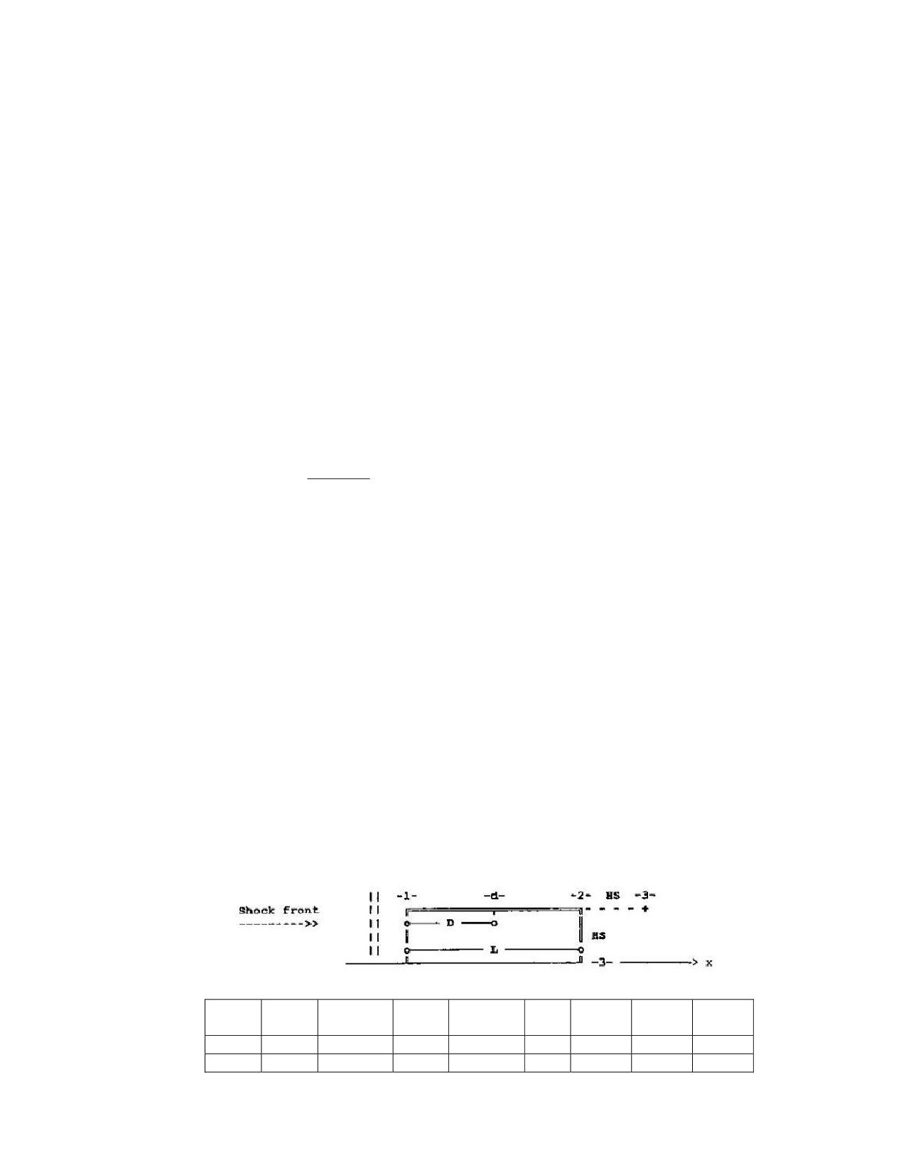
Basic equations
(1)
Symbols
(-->> List of Symbols)
S
Building height Hs or 0.5 · building width, whichever is the smaller value
Lw,x/L Ratio between blast wave length and span of the structural element under consideration
X Position index
S
Centre of element strip; relevant shock front position
(2)
Airblast Duration and Blast Wave Length
2 · Is,x
tof,x
eq [5-27]
Pso,x
Lw,x = U,x · to,x
(approximate value)
eq [5-28]
(3)
Equivalent Load Factors and Blast Wave Position Factor
The equivalent load factors and the blast wave position factor may be derived from Figure [5-3] or
determined using the following polynomial functions ….
C
=
Lw,x / L
Cx
=
0.0048 · C5 - 0.0584 · C4 + 0.2817 · C3 - 0.6963 · C2 +
0.9551 · C + 0.2433
eq [5-29]
D/L
=
0.0098 · C5 - 0.1203 · C4 + 0.5682 · C3 - 1.3207 C2 +
1.6217 · C - 0.0774
eq [5-30]
D
=
L · D/L
eq [5-31]
(4)
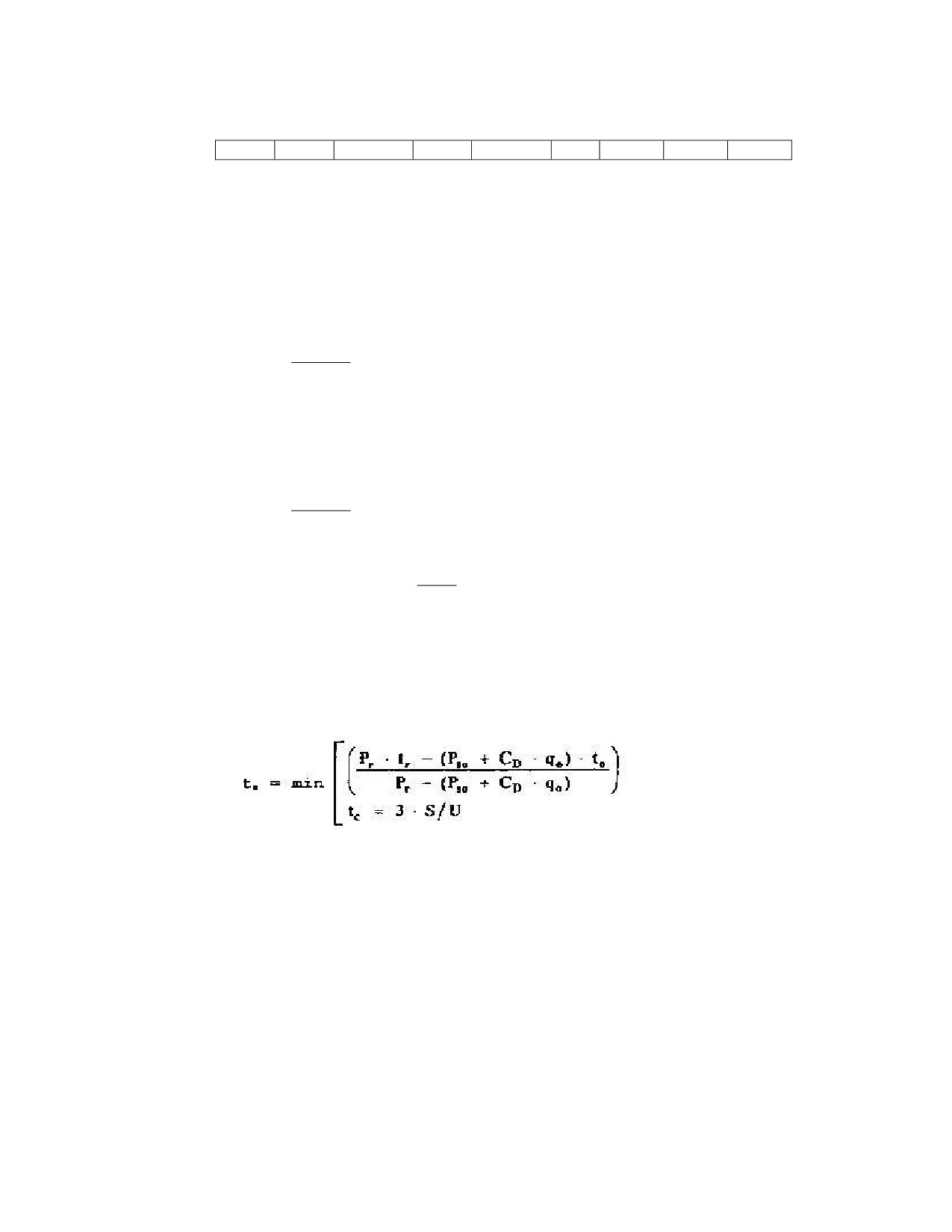
Determination of Characteristic Airblast Parameters
Pos
Pso,x
Is,x
Pr x
Ir,x
ta,x
to,x
U,x
Lw,x
(x)
MPa
MPa-ms
MPa
MPa-ms
ms
ms
m/s
m
1
+
+
+
+
+
+
+
+
2
+
+
-
-
+
+
+
+
-II-5-24-
Change 3
AASTP-1
(Edition 1)
3
+
+
-
-
+
+
+
+
Determination of parameters: (+) yes / (-) no
using: -->> Figure [5-2a] through [5-2f]
Front Face
- Bilinear Load Waveform:
(-->> Figure [5-4], [5-5], [5-6])
- Pressure duration, side-on overpressure:
2 · Is
tof =
(ms)
P
so
eq [5-32]
- Pressure duration, reflected overpressure:
2 · Ir
eq [5-33]
tr =
(ms)
Pr
-
ň
ʼn
qo
Iq = 0.5 · qo · tof = Is ·
(Mpa-ms)
Ň
Ň
P
so
Ŋ
ŋ
tof
Id = CD · qo ·
= CD · Iq
(Mpa-ms)
2
- Duration of peak reflected overpressure:
(ms)
- Total impulse:
I
= Is + Id + Ir* ≤ Ir
(Mpa-ms)
Ir* = 0.5 · (Pr - Pso - CD · qo) · ts
(Mpa-ms)
-II-5-25-
Change 3
AASTP-1
(Edition 1)
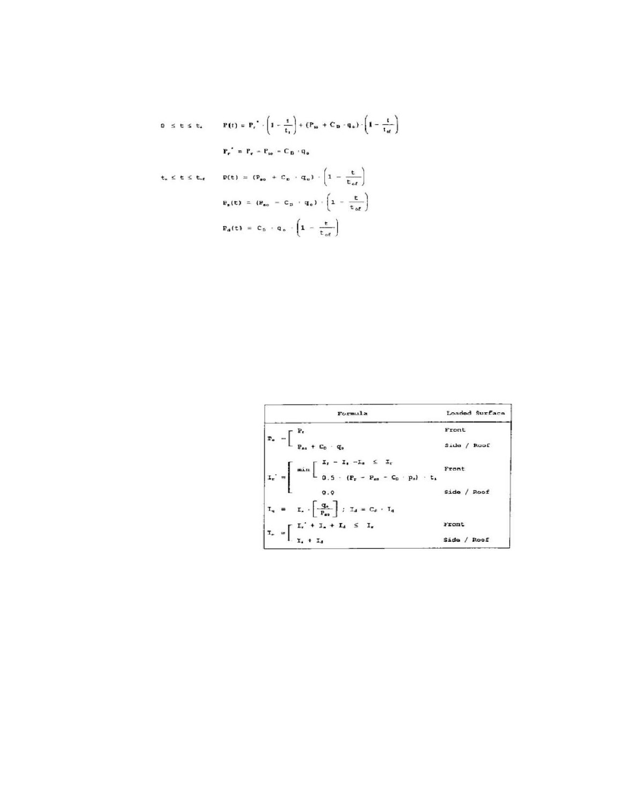
- Pressure waveforms: P(t) in (MPa)
- Exponential Load Waveform /Modified Friedländer equation:
(-->> Figure [5-5])
The bilinear pressure-time waveform may be transformed into an equivalent exponential function
which, from experience, has proved to correspond to the real airblast waveform.
- Pressure waveform:
Ps(t) = Po · (1 - t/to) · e(-β · (t/to))
(Mpa)
eq [5-34]
- Pressure drop constant:
β ≈ Po / Io
(---)
eq [5-35]
Peak Overpressure
Total Impulse
Roof and Side Walls
Direction of Span of Relevant Element is Perpendicular to the Shock Front, i.e. in Blast Direction
td
= D / U,2
t2,eff
= (ta,2 - ta,1) + tof,2
- Procedure:
-II-5-26-
Change 3

AASTP-1
(Edition 1)
. . . Determination of required airblast parameters from Figure [5-2a] through [5-2f]:
Pso,2 ; Is,2 ; U,2 ; to,2
. . . Determination of Lw,2 using eq [5-28]
. . . Determination of CE and D/L or D as functions of Lw,2 / L using Figure [5-3] or eq [5-29] through
[5-31]
. . . Determination of dynamic pressure qo,2 as a function of CE · Pso,2 using Figure [5-2b] or eq [5-4]
and [5-5]
. . . Determination of drag coefficient Cd related to qo,2 using Table [5-4]
. . . Calculation of peak overpressure and total impulse:
Po = CE · Pso,2 + CD · qo,2
I
s = 0.5 · Po · t2,eff
- Pressure waveform for t = 0 at front edge of structure:
t
0 ≤ t ≤ td
Ps(t) = Po ·
td
ň
ʼn
t
· td
td ≤ t ≤ t2,eff
Ps(t) = Po ·
1 -
Ň
Ň
t2,eff - t
d
Ŋ
ŋ
Direction of Span of Relevant Element is Parallel to the Shock Front;
Considering a Loaded Element Strip
(-->> Figure [5-5])
Assumption: Uniform time-dependent pressure loading of an element strip
2 · Is
tof,s =
Pso,s
Ls
td =
U,s
- Procedure:
. . . Determination of airblast parameters . . .
Pso,s ; Is,s ; U,s ; to,s
at position s, i.e. at the center of the element strip using Figure [5-2a] through [5-2f]
-II-5-27-
Change 3

AASTP-1
(Edition 1)
. . . Determination of dynamic pressure qo,s using Figure [5-2b] or eq [5-4] and [5-5]
. . . Determination of drag coefficient CD related to qo,s using Table [5-4]
. . . Determination of peak overpressure Po:
ň
0.5 · td
ʼn
Po = (Pso,s + CD · qo,s) ·
1 -
Ň
Ň
tof,s
Ŋ
ŋ
. . . Determination of total impulse Is:
Is = 0.5 · Po · (0.5 · td + tof,s)
-
Pressure waveform for t = o at front edge of element strip
t
0 ≤ t ≤ td = Ls/U,s
Ps(t) = Po
td
ň
ʼn
t - td
Ps(t) = (Po ·
1 -
td ≤ t ≤ 0.5 · td + tof,s
Ň
Ň
tof,s - 0,5 · td
Ŋ
ŋ
Rear Wall
As soon as the shock front passes the rear edge of the roof or the side walls, the blast wave expands
and produces secondary waves which propagate across the rear wall and will partly be reflected by the
ground.
An equivalent uniform time-dependent pressure load is calculated for the rear wall as well.
2 · Is,3
tof,3 =
Pso,3
D
td
U,2
t3,eff = [ 2 · Hs / (U,2 + U,3) ] + tof,3
(rough)
t3,eff = (ta,3 - ta,2) + tof,3
(exact)
Lw,3 = U,3 · tof,3
(rough)
-
Procedure:
... Determination of required airblast parameters from Figure [5-2a] through [5-2f] ...
Pso,3 ; Is,3 ; U,3 ; U,2 ; to,3
. . . Determination of factors CE and D/L or D as functions of the ratio Lw,3 / Hs using eq [5-28] or
Figure [5-3]
. . . Determination of td
-II-5-28-
Change 3

AASTP-1
(Edition 1)
. . . Determination of dynamic pressure qo,3 as a function of CE · Pso,3 using Figure [5-26] or eq [5-4]
. . . Determination of drag coefficient CD as a function of qo,3 using Table [5-4]
. . . Determination of peak overpressure and total impulse at position -3- . . .
Peak overpressure: Po = CE · Pso,3 + CD · qo,3
Total impulse : Is = 0.5 · Po · (t3,eff)
- Pressure variation for t = 0 at rear edge of structure:
t
0 ≤ t ≤ td
Ps(t) = Po ·
td
ň
t - td
ʼn
td ≤ t ≤ t3,eff
Ps(t) = (Po ·
1 -
Ň
Ň
t2,eff - td
Ŋ
ŋ
2.5.2.6
References
Essential references -->> Section VIII
Ref
[1], [3], [4], [5], [17], [45], [52], [53], [54], [62], [65], [72], [73], [76], [77], [78], [81], [82], [83],
[84], [85], [86], [87], [88], [101], [102], [128], [133]
-II-5-29-
Change 3

AASTP-1
(Edition 1)
Section IV - Projections
- Fragments, Debris, Lobbed Ammunition -
2.5.3.1
Introduction
General
An explosion of an ammunition storage site produces the following four types of projections:
-
Ammunition fragments
-
Debris from earth cover
-
Structural debris
-
Crater ejecta
The following discussion attempts to set forth principles and guidelines which may be useful for the proper
design of shelters and layout of safe ammunition and explosives storage areas when standard quantity distance
tables cannot be applied. Effective administrative safety provisions and, in particular, structural measures
against fragment and debris hazards may permit the reduction of quantity distances, thereby lowering the costs
for the construction and maintenance of ammunition storage facilities to a considerable extent.
Problem Description
The assessment of fragment and debris hazard is for the most part based on probabilistic approaches. The
reason for this is the fact that fragmentation and debris forming is a random process occurring under physical
environmental conditions which are not exactly definable.
Proposed Solution
Ballistic and distribution parameters form the basis for the damage assessment of projections, i.e. for
establishing their hazard characteristics and hazard potentials. Ballistic parameters are initial velocity,
horizontal and vertical angles of departure as well as mass whereas distribution is determined with respect to
number and mass of projections.
The vulnerability of the respective target is related to the damaging effect of the projections in order to
determine the hazard level.
2.5.3.2
Fragments
General
An explosion event in an ammunition storage building involves a hazard from emitted fragments generated by
detonating ammunition items in the Potential Explosion Site (PES).
Fragment generation essentially takes place in two phases:
-
During the explosion
-
After the explosion event due to detonation of ammunition items being ejected from the
potential explosion site or impacting on a hard surface
With cylindrical ammunition items, most of the fragments are projected in radial direction while only
a few heavy fragments are emitted from the nose and base at a low velocity. For worst case
considerations, it is assumed that the ammunition item detonates with its longitudinal axis parallel to
the respective structural component.
-II-5-30-
Change 3

AASTP-1
(Edition 1)
The emission of direct fragments from a potential explosion site depends on the properties of the respective
structural components as well as on the time relation between fragment movement, airblast propagation, and
build-up of chamber pressure.
The decisive parameters are …
-
Loading density;
-
Arrangements of stored ammunition;
-
Ammunition type.
For aboveground storage of ammunition, the following hazard levels are distinguished depending on the type
of storage.
-
Open storage
Full fragment hazard
-
Ammunition storage building without earth cover
Reduced fragment hazard.
High fragment absorption by structural components.
The velocity of impeded fragments is reduced by approx. 85% (energy absorption ≈ 95%).
Locations of high fragment hazard are the front area and the doors of the ammunition storage
building.
-
Earth-covered ammunition storage building
Little to no fragment hazard.
Due to the inert behavior of the structure and earth cover mass, the high velocity fragments are almost
completely absorbed.
Fragment Mass Distribution
(1)
Constant
MA = Bx · tc5/6 · di1/3 · ( 1 + tc/di)
(kg)1/2
eq [5-36]
Bx (kg1/2) / ( m7/6)
explosive constant in accordance with Table [5-6]
tc (m)
casing thickness
di (m)
inner casing diameter
(2)
Number of Fragments
Fragment mass distribution is represented in the form of the cumulative distribution of the number
of fragments Nf, individually heavier than a defined mass Mf, as a function of Mf. Such a function
may be derived directly from the results obtained by testing or determined analytically using the
Mott distribution:
eq [5-37]
Formulation according to Ref [2], [3], [4]
eq [ 5-38]
-II-5-31-
Change 3

AASTP-1
(Edition 1)
Total number of fragments:
Nt = Mc / (2 . MA2)
eq [5-39]
Mass of nominal fragment for design purpose:
Md = MA2 . In2(1 - CL)
for … 0.9500 ≤ CL ≤ 0.9999
for … 0.9999 ≤ CL ≤ 1.0000
Number of fragments individually heavier than Mf :
Detonating stacks of ammunition tend to produce mass distributions with a relatively higher
percentage of heavy fragments than single items detonating individually.
For practical purposes, the number of heavy fragments is the most important parameter, since they
are the most effective fragments with regard to ballistics and energy content.
A distribution of the form given above (Mott distribution), but with its main emphasis on the heavier
portion of the fragment spectrum, is useful for representing test results and defining hazard levels.
Fragment Ballistics
If the mass distribution, angles of departure and initial velocities of fragments at the point of origin are
known, trajectories, impact parameters and distribution density of the fragments can be determined.
Gravity and atmospheric drag are essential parameters affecting the trajectory, which should be taken
into account, at any rate, in order to find a safe and economical solution.
(1)
Ballistic Properties
Preformed and irregular fragments may be assumed to be geometrically similar.
Fragment mass Mf and presented area Af are proportional and related by the shape factor k . . .
Mf = k · Af 3/2
eq [5-40]
This shape factor or ballistic density is determined empirically from ballistic tests and depends on
the type of ammunition.
(-->> Table [5-7])
(2)
Initial Velocity
Besides field measurements during fragmentation trials, the initial velocity of a fragment may be
estimated from the . . .
. . . Gurney formula :
-II-5-32-
Change 3

AASTP-1
(Edition 1)
Vo = G / ((Mc/Mex) + (n/ (n+2)))1/2
eq [5-41]
G = √(2·E)
Gurney velocity, a constant for a given explosive Values:
-->> Table [5-6]
n
Geometrical constant:
-->> Table [5-8]
The basis for the equation above is an analysis of the behavior of a cylindrical or spherical casing
subjected to an internal gas pressure. For projectiles, the formula may only be applied to fragments
emitted radial from the casing.
Note:
The Gurney formula is not mass-dependent and applies primarily to fragments of up to 150
g, approximately. For heavier fragments, the formula gives a conservative result, since lower initial
velocities are to be expected. The Gurney formula is adapted to different types of ammunition. Thus,
there are different Gurney constants and geometrical constants. The literature referenced below
contains details and additional formulations for the determination of initial velocities.
Ref [164 et al] -->> additional formulations:
. . Modified Gurney formula
. . Lukanow-Molitz formula
. . Swedish formula
. . Allison-Schriempf formula
. . Gabeaud formula
(3)
Angle of Departure
Fragments from individual items of ammunition normally depart radial from the casing. Depending
upon the type of ammunition, the area fragment distribution varies along the projectile axis.
For details and modeling procedures refer to the literature reference in Section VIII.
- e.g. Ref [171], [173], [174]
(4)
Trajectory
For design purposes in the far-field range (with regard to the explosion site) the influence of gravity
is essential. When designing shelters, or if the near field is concerned, the effect of gravity is
negligible and straight trajectories may be assumed.
Non-linear fragment trajectories are very important for safety-related analyses of ammunition.
(5)
Trajectory Calculation
Fragment trajectories are usually calculated with computers using numerical formulations since
closed solutions are impossible due to the complex parameters such as wind, atmospheric drag etc.
influencing the trajectory.
For this purpose, efficient programs considering the essential parameters affecting the trajectory are
available.
(-->> ref [201], [203])
Trajectory Calculation Procedures and References :
Subject Matter
References
(1)
Exterior Ballistics of Fragments
[164]
CD Values for Irregular Fragments
(2)
Mass and Shape Distribution
[163]
Laws for Irregular Fragments
[4]
(3)
SIACCI Method
[165]
-II-5-33-
Change 3

AASTP-1
(Edition 1)
(4)
Primary and Secondary Fragments
[211], [4]
(5)
Fragmentation
[211], [1]
(6)
Fragment Protection
[3]
(6)
Trajectory Velocity
For the practically relevant range, the fragment velocity as a function of distance can be estimated from the
exponential function below, assuming a constant drag coefficient and disregarding gravity.
The CD-value can be obtained from Figure [5-7] or Table [5-9] :
V(R) = Vo . e(-R/L)
eq [5-42]
2 · (k2 · Mf)(1/3)
L =
eq [5-43]
(CD · rho)
(7)
Impact Velocity
The impact velocity varies between the near-field limits (low-angles of departure) according to eq
[5-44] and the far-field limits (long fragment distance) according to eq [5-45], with the latter
physically representing the terminal velocity in free fall.
- Conservative formulas for the estimation:
. . . near field:
Vi = Vo · e(-(Re/L))
(m/s)
eq [5-44]
. . . far field:
(m/s)
eq [5-45]
- According to Ref [1], [3] . . .
Vi = Vo · e(-(0.004·Re·/Mf(1/3))
(m/s)
eq [5-46]
(8)
Impact Angle
The fragment impact angle depends upon the departure parameters and other external conditions
(wind, air density, fragment parameters etc.).
For design purposes, normal impact, i.e. ai = 90o, is to be assumed.
(9)
Impact Energy/Impact Impulse
Impact energy and impact impulse, respectively, are decisive parameters for the assessment of
fragment hazard levels.
The fragment mass Mf and the impact velocity Vi are essential parameters.
Mf · Vi2
Impact energy: Ekin = Ei =
(J)
eq [5-47]
2
Impact impulse: Ii
= Mf . Vi
(Ns)
eq [5-48]
-II-5-34-
Change 3

AASTP-1
(Edition 1)
(10)
Fragment Number Density
The probability of fragments striking a target (ES) at a given position is determined by the area
density of flux of fragments, through the target area projected on a plane normal to the fragment
trajectory at impact. When gravity effects are considered, numerical calculation techniques must be
utilized even if simplifying assumptions have to be made regarding atmospheric drag and the mass
distribution of the fragments. If gravity is ignored, however, the fragment flux with respect to
distance follows an inverse-square law.
Assuming:
-
The Mott fragment mass distribution;
-
Fragment masses greater than the defined mass Mf ;
-
A target area normal to the fragment trajectory at a distance R.
The area density qf of fragments is given by:
Qo
qf =
e(-(2Mf/Mo)1/2)
(Number / m2)
eq [5-49]
R2
Determination of Qo on the basis of the individual fragment distribution curves for ammunition or
according to
-->> Ref [1], [3], [4]
In this approximation, consideration of the influence of gravity refers to its effect on impact velocity
but not to the terminal phase of the trajectory.
The effective value of Qo
, Qo,eff depends upon the prevailing storage conditions. The effective
value for fragments from a stack of ammunition is estimated by multiplying the value for a single
ammunition item by the effective number of items NE.
Qo,eff
= Qo · NE
eq [5-50]
-
For a stack in the open, NE is derived from:
NE = 0.9 · Ns + 0.1 · NT
eq [5-51]
-
For a stack in an earth-covered magazine NE is:
NE = 0.7 · Ns + 0.1 · NT
eq [5-52]
Where
NE
Effective number of items of ammunition
Ns
Number of items of ammunition on the side of the stack facing the
potential target
NT
Number of items of ammunition in the top layer of the stack.
Hazard Potential
(1)
Probability of Impact
The probability of impact Pf of an individual fragment or a fragment flux is calculated using the
area density qf .
The impact process is assumed to be uniformly random in the vicinity of the target point, so that
fragment impact is equally probable on all equal area elements in the vicinity of the point. The
-II-5-35-
Change 3

AASTP-1
(Edition 1)
probability of impact Pf of one or more fragments of a mass Mf or greater on a given target area is
thus given by:
Pf = 1 - e(-qf·AT)
eq [5-53]
qf
(Number/m2)
with eq [5-49]
AT (m2)
target area
For a standing man, e.g., facing the explosion:
. . . AT ≈ 0.56 m2
(2)
Hazard Criteria / Hazard Levels
Fragment hazard levels for a given target are determined using the essential parameters below:
-
Fragment density at the target or hit probability of the individual fragment or the fragment
flux;
-
Impact energy - kinetic energy - of the individual fragment:
Ekin = Ei = (Mf · Vi2) / 2
(Nm)
eq [5-54]
-
Impact impulse of the individual fragment:
Ii
= Mf · Vi
(Ns)
eq [5-55]
-
Vulnerability / destructibility criteria of the target in question.
(3)
Injury Criteria / Casualty Criteria
A variety of functions of impact velocity and fragment mass have been proposed as injury criteria.
NATO-wide, a lethal fragment is defined as a fragment with a kinetic energy exceeding the critical
value of 79 Joules. This limit applies to fragment masses ranging from a few grams to several
kilograms. In most cases, severe injuries will be caused.
Further details -->> Section VII
Fragment Calculation Procedure
(1)
Calculation of the initial fragment velocity
using the . . .
-
GURNEY-Constant
Table [5-6]
-
GURNEY-Formula
eq [5-41]
-
with n = 2 for cylindrical projectiles
(2)
Calculation of the number of fragments
. . . per unit solid angle based on the number of fragments Qo or Qo,eff emitted from an item of
ammunition or ammunition stack in the direction of interest. This is usually the direction
perpendicular to the ammunition axes.
-II-5-36-
Change 3

AASTP-1
(Edition 1)
(3)
Determination of the average fragment mass Mo
using . . .
-
Available data bases;
-
The average mass Mo of an individual item of ammunition, obtained by fitting a Mott
distribution to data from a single item, emphasizing the heavier fragments within the mass spectrum.
In order to account for the greater ballistic and energetic effectiveness of fragments from stacks of
ammunition, a shape factor k = 4.74 g/cm3 will be assumed.
(4)
Determination of the mass Mf of the lightest hazardous fragment
Reaching a specified distance R using a parameter for the critical kinetic energy of a hazardous
fragment.
Formulation 1:
The terminal energy of a fragment of mass Mf in free fall is less than the
critical energy.
Ecr
Mf = 2 ·
(kg)
eq [5-56]
Vi2
Vi = Vo · e(-R / L)
(m/s)
2 · k(2/3)
L =
· Mf(1/3)
(m)
CD · rho
Formulation 2:
The terminal energy of a fragment of mass Mf in free fall is greater than
the critical energy.
3/4
ň
ʼn
(kg)
eq [5-57]
2 · Ecr
Mf
Ň
Ň
g · L1
Ŋ
ŋ
Notes:
- Whichever gives the smaller value of Mf will be used.
- For Ecr = 79 Joules and k = 4.74 g/cm∧3 the transition occurs at Mf = 0.1 kg, approximately.
(5)
Calculation of the area fragment density
For fragments heavier than Mf and distance R in accordance with eq [5-49].
Alternatively, the distance R at which the critical density qcr
(1/56 m2) for hazardous fragments is
exceeded will be determined iterative using eq [5-49], [5-56] and [5-57].
Note:
The result is the larger of the two values of R so obtained.
(6)
Determination of the injury probability
The determination of the injury probability p at distance R from eq [5-53].
For small values of qf , the following approximation applies:
p ≈ q · AT
eq [5-58]
-II-5-37-
Change 3

AASTP-1
(Edition 1)
Notes:
-
The procedure above can be adapted for use with an injury criterion other than impact
energy.
-
Ballistic terminal parameters from other calculations may of course be introduced.
(7)
Stacks Effects
There are strong indications that the fragmentation characteristics of stacks of ammunition differ
significantly from those of a single detonating item.
-
Detonating stacks emit a higher number of larger or heavier fragments.
This effect is influenced by the charge-to-metal (casing) ratio. Ammunition with small values of this
ratio (e.g. artillery projectiles) generally produce fragments of greater individual mass.
-
The initial fragment velocities for stacks of ammunition have been observed to be almost
twice as high as for fragments from single items of ammunition.
-
In the case of mass detonations, only the items of ammunition on the sides and top of a
rectangular stack appear to contribute to the far-field area density of hazardous fragments.
2.5.3.3
Debris and Crater Ejecta
Structural Debris
(1)
General
An accidental explosion in an ammunition storage facility produces an impulsive peak overpressure leading to
the shattering of or heavy damage to the structure. The resulting structural debris generally come
from walls, foundation, bottom slab, ceiling, piers, screens, and fixtures.
The subsequent 'quasi-static' internal pressure ruptures the building and vents through newly
created or existing openings. Shattered structural components and other objects located on or within
the building are accelerated by the releasing overpressure and projected from the explosion site.
Main debris distribution is approximately normal to or at an acute angle to the original building
walls or main axes.
These debris constitute a substantial hazard to objects and personnel in the vicinity.
The size of the structural debris depends upon the . . .
-
. . . Construction of the building,
-
. . . Material of the building and the strength of the material,
-
. . . Type of ammunition,
-
. . . Loading density.
Small structural debris are to be expected in the case of . . .
-
. . . Increasing loading density,
-
. . . Brittle material,
-
. . . Low-strength material,
-
. . . Thin-walled structural component,
-
. . . A small percentage of reinforcement,
-
. . . Pre-damaging due to fragment impact.
Larger structural debris are to be expected in case of . . .
-II-5-38-
Change 3

AASTP-1
(Edition 1)
-
. . . A solid, heavy construction,
-
. . . Strong reinforcement,
-
. . . Tough material,
-
. . . Low loading density,
-
. . . A blast effect alone.
(2)
Debris Mass Density
Detached Ammunition Storage Building
The debris/fragment departure from a detached ammunition storage building depends on several
parameters, i.e . . .
-
. . . Loading density,
-
. . . Type of ammunition/casing factor,
-
. . . Geometry and strength of the building,
-
. . . Direction of debris departure with regard to the building.
In Ref [76] the debris mass density is given by the following equation . . .
(-0.29)
rho,deb = 0.36 · Ma · (0.58) · e(-0..047·R·Q )
(kg / m2)
eq [5-59]
all masses are in tons (to) = 1,000 kg
R (m)
distance from the building center
f1
-->> Figure [5-8]
Vi (m3)
internal volume of building
Q (to)
=
NEQTNT (to)
-
Ma . . . Total mass of ejecta
Ma = Mo + Mg + Mm
(to)
-
Mg . . . Mass of building
Mg = f1 . Vi
(to)
-
Mo . . . Ejected earth mass of apparent crater
Mo ≈ 100 · NEQTNT
(to)
-
Mm
… mass of ejected ammunition components in (to)
Estimates:
Mm ≈ 0.0
mines and high explosive
Mm ≈ 0.25 · Vi
cased ammunition
Earth-Covered Ammunition Storage Building
In addition to the parameters decisive for the debris projection from detached ammunition storage
buildings, in this case also the type, geometry and mass of the earth cover are of importance
(-->> Ref [75]) …
rho,deb = 0.036 · Ma · e(-0.015·R) )
(kg / m2)
eq [5-60]
-II-5-39-
Change 3

AASTP-1
(Edition 1)
all masses are in tons (to) = 1,000 kg
R (m)
distance from the building center
f1
-->> fig/[5-8]
Vi (m3)
internal volume of building
-
Ma . . . Total mass of ejecta
Ma = Mo + Mg + Mm
(to)
-
Mg . . . Mass of building
Mg = f1 · Vi
(to)
-
Mo . . . Ejected earth mass of apparent crater and earth cover (standard) empirical
hypothesis:
mass of standard earth cover ≈ 4 to 5 · Mg
Mo ≈ 100 · NEQTNT + 4 · Mg
(to)
-
Mm . . . mass of ejected ammunition components (to)
Estimates:
Mm ≈ 0.00
mines and high explosive
Mm ≈ 0.25 · Vi
cased ammunition
(3)
Ballistics
Because of the high complexity of the event, it is very difficult to reliably determine the ballistic
parameters of structural debris or crater ejecta resulting from an accidental explosion. There are not
as many fundamental and other basic data available as is the case for fragments.
The departure parameters - velocity, angle, and mass - may vary substantially with the explosion
environment. The engineer de-signing potentially exposed sites must, under these conditions,
normally rely on threshold functions.
Velocity of Departure
The velocity of departure is dependent upon the loading density, the type of explosive, the structural
strength, and the point of departure of the debris.
The full scale tests described, e.g., in Ref [86], [106], where fragments and debris have been
thoroughly recorded and evaluated, confirm the above statements. Normally, fragments are
accelerated more effectively than building debris or crater ejecta because of the higher loading
density.
Depending upon the structure of the building and the loading density, more or less massive
structural debris nevertheless can achieve velocities of departure of up to Vo = 1,000 m/s.
Since their mass is generally greater than that of fragments, they must be considered to have a higher
energetic effectiveness in the far field.
Angle of Departure
Generally, structural debris will depart at an angle normal to the structure surface. Vertical and
horizontal angles of departure vary from approximately ±10o to ±20o. Depending upon the loading
-II-5-40-
Change 3

AASTP-1
(Edition 1)
density and the structural design of the building at intersections and junctions of components, angles
of departure of up to approximately 30o from the normal may occur due to angular moments at the
time of departure.
(-->> Ref [155], [157], [200], [211])
(4)
Hazard / Damage Predictions
The hazard level with respect to personnel or material depends upon the local situation and the
predominant type of load. Debris impact density and impact energy constitute essential hazard
parameters.
Detailed Hazard Data -->> Section VII
Inside inhabited buildings situated at the required quantity distance to the explosion site, the hazard
to persons is mainly due to secondary debris formed in the close vicinity by the air-blast. The limit
pressure currently specified for inhabited buildings is approximately 5 kPa.
(-->> Section VII).
This overpressure causes minor structural damage such as glass breakage, cracks in plaster, and
damage to the exterior wall lining.
Debris from Earth Covers and Crater Ejecta
(1)
General
Soil and rock material being ejected from the explosion crater is defined as "crater ejecta". In the
case of accidental explosions involving only individual ammunition components or small quantities
of explosives, the load case "crater ejecta" generally constitutes a minor potential hazard as
compared to the other effects such as airblast, fragments, structural debris and shock.
In the case of surface bursts of larger quantities of explosives, however, a substantial debris hazard
has to be assumed, and the load case "crater ejecta" has to be taken into account in the safety-related
assessment of ammunition facilities and their surroundings.
The cover material of earth-covered ammunition storage facilities produces additional ejecta. With
standard installations, this covering material should consist of fine-grain particles with a relatively
small mass. Projection distance and impact energy of this material are generally less than that of
structural debris.
(2)
Mass Density
In Ref [31], the mass density of the crater ejecta for an open surface burst is given by the following
mean relationship. .
rho,ej = 27 · NEQTNT1.4 · R(-3.6)
(kg / m2)
eq [5-61]
NEQ (kg) ; R (m)
(3)
Ballistics
The ballistic performance of crater ejecta is similar to that of structural debris.
Formulations for ballistic parameters of crater ejecta have been examined and developed.
-->> Ref [31], [32], [33], [76], [77].
-II-5-41-
Change 3

AASTP-1
(Edition 1)
Ejecta Range
In the case of explosions on the surface of or inside cohesive soil, the total mass of ejecta is to be
found within the following range . . .
Rej ≈ 30 · Ra
eq [5-62]
The maximum projection distances of crater ejecta are determined by an NEQ0.4 - law and depend
upon the type of soil . . .
. . . for rock
:
Rej,max = 30 m/kg 0.4
. . . for soil
:
Rej,max = 12 m/kg 0.4
(4)
Hazard Area (estimated)
Explosions on the surface of or inside cohesive soil or rock lead to longer ejecta distances.
The data from Table [5-10] may be used as estimates for these cases.
(5)
Hazard Criteria
The hazard from ejecta (crater, earth cover) is due to their kinetic energy (impact force) upon impact
and due to their penetration or punching capability. This primarily affects weaker structural
components such as roofs, ceilings and large walls of relatively low thickness.
Whereas less solid ejecta material (gravel, sand, clayey sand, clay, etc.) crumbles upon impact or is
subjected to heavy deformations, solid, practically undeformable material (e.g. rock, broken stone,
gravel) has a hazardous penetration and punching capability.
Penetration by "Undeformable" Ejecta
"Quasi-undeformable" ejecta transfer high, short shock impulses to the target material exposing it
to risk of punching or perforation.
The penetration capability of high-strength rock (basalt, granite) as compared to soft rock (friable
standstone, slate) may be assumed to be 7 to 1 .
Figure [5-9] shows the penetration of mild steel plate by hard rock ejecta.
Figure [5-10] shows estimates of the perforation threshold of non reinforced concrete slabs for the
impact of hard rock ejecta.
The diagrams are based on the conservative assumption of an impact of "undeformable" ejecta in a
realistic velocity range.
Hazard thresholds for persons and material -->> Section VII
(6)
Load Assumptions for Structural Component Design
Undeformable Crater Ejecta
The design of structural components assuming dynamic loads can be facilitated in the case of solid
ejecta using the "impulse formulation".
(-->> Ref [7 (2.3 and 5.5)], [3])
Shock Impulse:
I = Mej · Vi
(Ns) eq [5-63]
-II-5-42-
Change 3

AASTP-1
(Edition 1)
I2
yel
Maximum Deformation:
ym =
+
(m) eq [5-64]
2 · Mstr · Rm
2
Deformable Crater Ejecta
Moist, cohesive ejecta is deformed upon impact and acts as solid ejecta with a lower peak impulse,
but a longer effective duration.
Building damages are caused less due to punching than to local bending failures.
A simplified structural component design assuming a dynamic load can be carried out with the
following formulations . . .
Vf
=
0
1d
≈
1.12 · (Mej / rho) 1/3
(m)
Vm
=
(Vi + Vf) / 2
(m/s)
Mean shock impulse:
Im = Mej · Vm
(Ns)
Deformation assumption (empirical) : xpl = 2/3 · 1d
(m)
Shock period:
xpl
2 · ld
td =
+
Vm
2 · vm
Load:
. . . Peak load for triangular load history:
2 · ldm
Fmax =
(N)
td
. . . Peak load for constant load history:
Im
Fd =
(N)
td
Figure [5-10] shows estimates for the maximum shock loads of long distance ejecta.
(-->> Ref [1])
Dynamic Strength Increase
The short-time loading of protective structures - ammunition storage magazines, aircraft shelters,
etc. - involves an increase in strength of the loaded material as a function of loading rate.
For the load cases described, the "Dynamic Increase Factor" (DIF) should be selected from the
values given in Table [5-11] and Ref [1], [4] respectively.
-II-5-43-
Change 3