Engine PT6A-60 SERIES. TRAINING MANUAL (2007) - page 2
ENGINE INDICATING SYSTEM
Function:
- Provide the pilot with indications concerning the
engine parameters during flight
- Provide the required data for engine condition trend
monitoring and performance
Engine Indicating Systems:
- Ng / Np Tachometer-Generators (Pulse pick-up probes
on the PC12)
- Oil temp/ Oil pressure indication
- Chip detector
Indicating Systems Built Into Engines:
- Inter turbine temperature system (T5)
- Torque indication system
PT6A-60 SERIES
TRAINING USE ONLY
ENGINE INDICATING SYSTEM 7.2
P&WC Proprietary - Disclosure and use subject to the restrictions on page 2 of preface
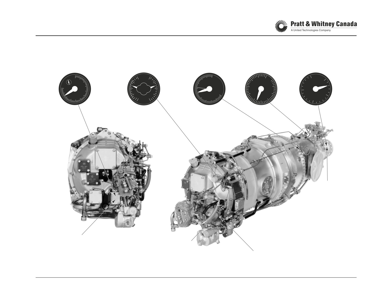
ENGINE INDICATING SYSTEM
COMPRESSOR SPEED
OIL TEMPERATURE (C˚)
ITT
TORQUE
PROPELLER SPEED
NG (%)
AND PRESSURE (PSIG)
(C˚)
(FT-LBS)
Np (RPM)
0
21
OIL
9
01
11
12
45
50
20
0
8
2
14
20
START
40
0
7
3
PROP RPM
6
4
%
23
10
15
9
ITT
TORQUE
5
35
11
RPM
6
10
FTLB
5
X 100
4
8
˚c x 100
x100
15
10
2
PSI
5
7
2
30
10
X 100
5
5
9
6
0
x 10
6
8
7
-2
0
5
3
25
15
4
20
10
Np TACHO
GENERATOR
Ng TACHO
OIL PRESSURE
GENERATOR
TRANSMITER PORT
OIL TEMPERATURE
BULB
PT6A-60 SERIES
TRAINING USE ONLY
ENGINE INDICATING SYSTEM 7.3
P&WC Proprietary - Disclosure and use subject to the restrictions on page 2 of preface
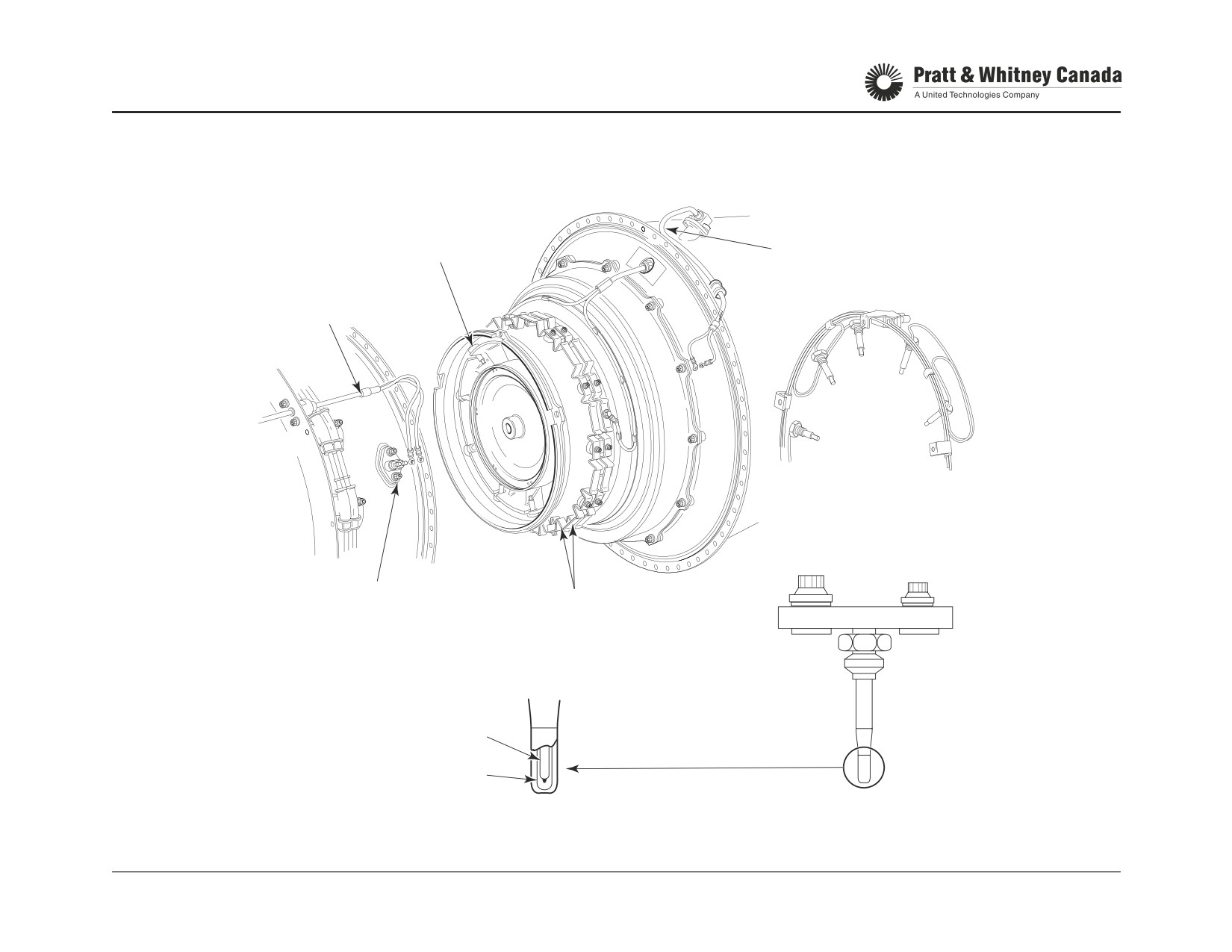
INTER-TURBINE TEMPERATURE (T5)
Function:
Provides an indication of the Inter-Turbine Temperature
(ITT), between the compressor turbine and the first stage
power turbine vane ring (station 5).
Description:
- 10 individual thermocouples (chromel-alumel)
- 1 positive bus bar (chromel-small terminal)
- 1 negative bus bar (alumel-large terminal)
- 1 trim probe
- 1 T5 wiring harness
Note:
Engine operation at or above maximum temperature may
damage or shorten hot section component's life
PT6A-60 SERIES
TRAINING USE ONLY
ENGINE INDICATING SYSTEM 7.4
P&WC Proprietary - Disclosure and use subject to the restrictions on page 2 of preface
TEMPERATURE INDICATING SYSTEM (T5)
THERMOCOUPLE
WIRING HARNESS
TRIM PROBE
PRE-SB 13038
(A-60/61/65)
TERMINAL BLOCK
BUS-BAR
ALUMEL LEAD
CHROMEL LEAD
INDIVIDUAL
THERMOCOUPLE JUNCTION
THERMOCOUPLE
PT6A-60 SERIES
TRAINING USE ONLY
ENGINE INDICATING SYSTEM 7.5
P&WC Proprietary - Disclosure and use subject to the restrictions on page 2 of preface
TEMPERATURE INDICATING SYSTEM (ITT)
Operation:
Maintenance:
- Check system loop resistance (continuity)
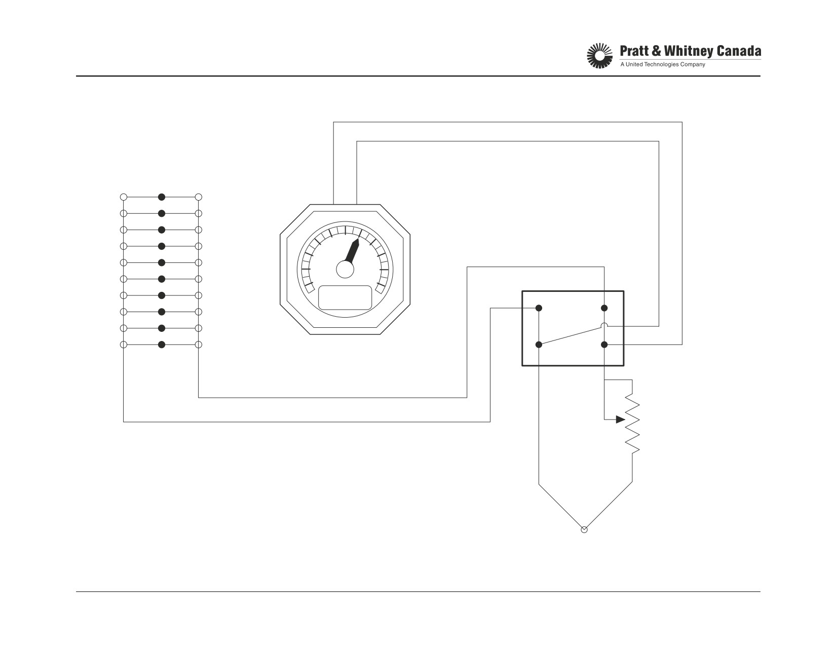
As temperature increases, an increasing voltage is gener-
- Check resistance of individual probe
ated at the chromel/alumel junction of each thermocouple.
- Check insulation resistance (harness, probe and trim
probe)
Uneven heat distribution within the gas path causes individ-
- Check probes for heat response
ual thermocouples to see different temperatures and gener-
- Check Trim thermocouple adjustment
ate different voltages.
To obtain an average reading, the thermocouples are con-
Troubleshooting:
nected in parallel. The indication generated is the average
temperature of 10 specific locations (thermocouple tips)
Problem Area
Symptom
within the gas path and therefore does not necessarily rep-
resent the exact average temperature at station 5. The
Burnt Probes
T5 drops due to loss of probes
exact average temperature is calculated at engine test and
in hot spots
is used to determine engine acceptance.
Short Circuit To Ground
T5 drops due to complete or
partial loss of T5 signal
A trim probe located over the inlet case is connected in par-
allel with the 10 thermocouples to bias the average temper-
Trim Probe Open Circuit
T5 increases due to loss of
ature reading. The resultant corrected temperature is read
trimming function
in the cockpit. The indication generated by the 10 probes at
station 5 is trimmed down using the trim probe internal
High Resistance On T5
T5 drops due to reduction of
resistor. The smaller the resistance the greater the down-
Circuit Between Engine
T5 signal
trim (the lower the ITT).
And Aircraft Gage
Trim Probe Resistance
T5 increases if trim resistance
The amount of trimming is a function of the trim probe inter-
Drifting
increases
nal resistance. The resistance of the trim probe is adjusted
T5 drops if trim resistance
at engine test to match the required temperature trim.
drops
PT6A-60 SERIES
TRAINING USE ONLY
ENGINE INDICATING SYSTEM 7.6
P&WC Proprietary - Disclosure and use subject to the restrictions on page 2 of preface
T5 SYSTEM SCHEMATIC
ALUMEL CHROMEL
VARIABLE
SEALED
RESISTANCE
BUS BARS &
(PRE SB 13338 &
THERMOCOUPLES
SB 14299)
TRIM PROBE
PT6A-60 SERIES
TRAINING USE ONLY
ENGINE INDICATING SYSTEM 7.7
P&WC Proprietary - Disclosure and use subject to the restrictions on page 2 of preface
TORQUE SYSTEM
Function:
Maintenance:
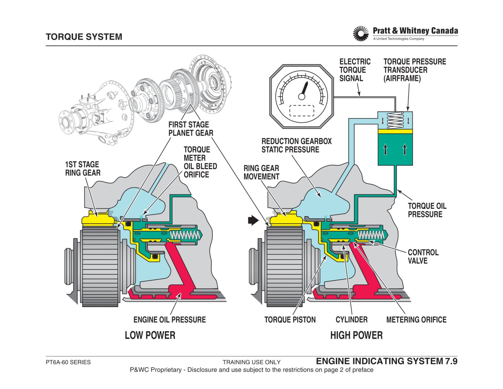
Provide an accurate indication of the torque applied to the
Check/calibrate the airframe torque transducer and gage
propeller.
(ref. to airframe maintenance manual).
Description:
Troubleshooting:
- Hydro-mechanical system
- Floating first stage ring gear with helical splines
Problem Area
Symptom
- Piston
- Cylinder
Control Valve
Torque goes off scale (high)
- Spring loaded oil control valve
Stuck Open
Worn Piston
Torque indication low
Operation:
Seal Rings
Set oil pressure to max limit
Torque applied to the propeller induces a small rotational
Defective Trans-
Torque may indicate high or low
and rearward movement of the first stage ring gear. This
ducer/Gage
movement is due to the helical splines on the ring gear.
The ring gear pushes the piston and the control valve.
Oil In RGB
Torque fluctuation
Static Line
Moving the control valve to the rear, opens the metering ori-
fice and allows more oil pressure to push on the piston
Reference:
against the ring gear mechanical force.
A52, A64
1 psi = 30.57ft/lb
The movement of the ring gear only stops when metered oil
pressure in the torque meter chamber exactly balances the
A60, A65
1 psi = 83.63ft/lb
rearward force of the ring gear. Static air pressure inside the
A66
1 psi = 37.04ft/lb
reduction gearbox acts on the torquemeter piston and
would cause incorrect (higher) torque reading. For this rea-
A67
1 psi = 86.63ft/lb
son, static pressure is sent to the transducer and subtracted
from the torque reading.
Hydrostatic lock is prevented by continuously bleeding oil
from the pressure chamber.
PT6A-60 SERIES
TRAINING USE ONLY
ENGINE INDICATING SYSTEM 7.8
P&WC Proprietary - Disclosure and use subject to the restrictions on page 2 of preface
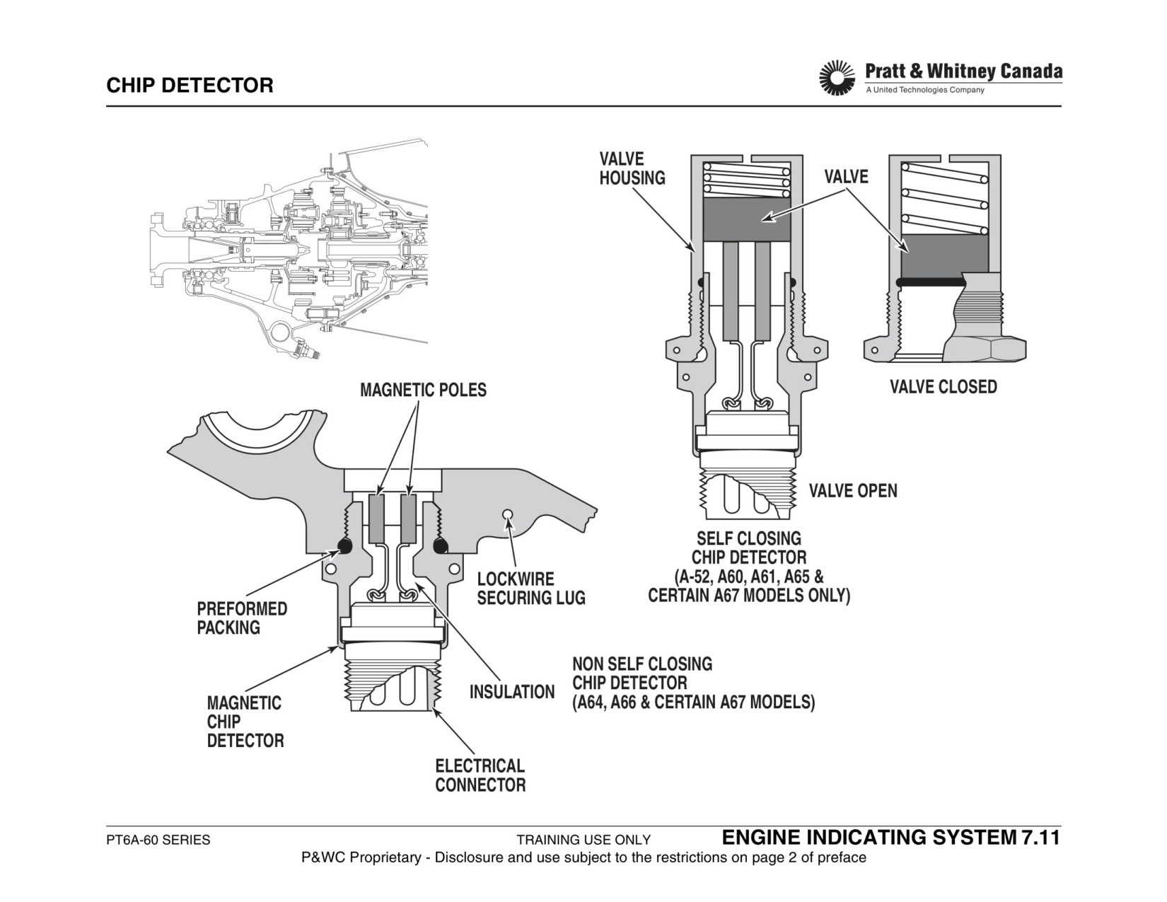
CHIP DETECTOR
Function:
Maintenance:
- Inspect chip detector at interval specified by aircraft
Provides an indication of metal particle contamination of the
maintenance manual
engine oil system.
- Functionally test chip detector
- 100hrs -> Check Continuity
- 600hrs/12Mo. -> Function Check
Description:
- Two magnetic poles
- Normally open circuit
Warning:
- Wired to a light in the cockpit (optional)
- Self closing valve allows chip detector verification with-
DO NOT OVERTORQUE THE CHIP DETECTOR
out draining the RGB (except A64/66)
Operation:
When metal particles accumulate on the two magnetic
poles and bridge the existing gap, the circuit closes.
Some installations use an indicator in the cockpit to warn
the pilot or maintenance people that contamination is
present. Other models rely on visual inspection and conti-
nuity check of the chip detector to detect contamination.
Particles found on the chip detector can be analyzed and
identified. Refer to chapter 70 of the Engine Maintenance
Manual.
PT6A-60 SERIES
TRAINING USE ONLY
ENGINE INDICATING SYSTEM 7.10
P&WC Proprietary - Disclosure and use subject to the restrictions on page 2 of preface
IGNITION SYSTEM
IGNITION SYSTEM
PT6A-60 SERIES
TRAINING USE ONLY
IGNITION SYSTEM 8.1
P&WC Proprietary - Disclosure and use subject to the restrictions on page 2 of preface
IGNITION SYSTEM
Function:
Exciter Box Specifications:
Input voltage
9-30 VDC
Provide the spark to ignite the fuel/air mixture.
Input current
3.5 amp
Operating Altitude
0-50000 feet
Description:
Spark rate 10 VDC
1 spark/sec
- Airframe mounted ignition exciter
30 VDC
4 spark/sec
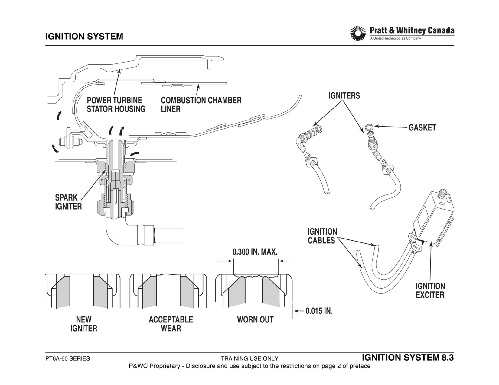
- Two high tension cables
Stored energy
4.7 joules
- Two spark igniters
Output voltage
8000 volts
Exciter Box:
Operation:
A sealed unit which transfers a DC low voltage input to a
Activated by the pilot for engine start. The system can
pulsed high voltage output. When the unit is energized, the
operate continuously during adverse weather conditions to
capacitor progressively charges until the voltage can ionize
allow the engine to re-light in the event the of engine flame
the spark gap then the capacitor discharges through the
out.
igniter plugs.
Maintenance:
Ignition Cables:
- Ignition plugs are not life limited.
Two cables carry the electrical energy from the exciter box
- Inspect cooling holes of spark igniters for blockage.
to the igniters. Each cable consists of an electrical lead sur-
- Inspect igniter shell and electrode for erosion.
rounded by an insulating tube contained in a flexible metal
- Carry out functional test by disconnecting one ignition
braiding.
cable at the exciter box. Switch ignition on and listen
for the spark.
Spark Igniters:
- Replace igniter plugs if dropped.
Located at 4 and 9 o'clock positions on the gas generator
- Check for fretting wear @ combustion chamber junc-
case, the spark igniters are in the form of threaded plugs
tion.
with a central electrode enclosed in an annular semi-con-
ducting material. When the voltage reaches a certain level,
Warning:
the air between the central electrode and the plug outer
shell ionizes a high energy spark discharges from the elec-
Wait six minutes after switching ignition off before
trode.
handling any ignition components.
PT6A-60 SERIES
TRAINING USE ONLY
IGNITION SYSTEM 8.2
P&WC Proprietary - Disclosure and use subject to the restrictions on page 2 of preface
PERFORMANCE
PERFORMANCE
PT6A-60 SERIES
TRAINING USE ONLY
PERFORMANCE 9.1
P&WC Proprietary - Disclosure and use subject to the restrictions on page 2 of preface
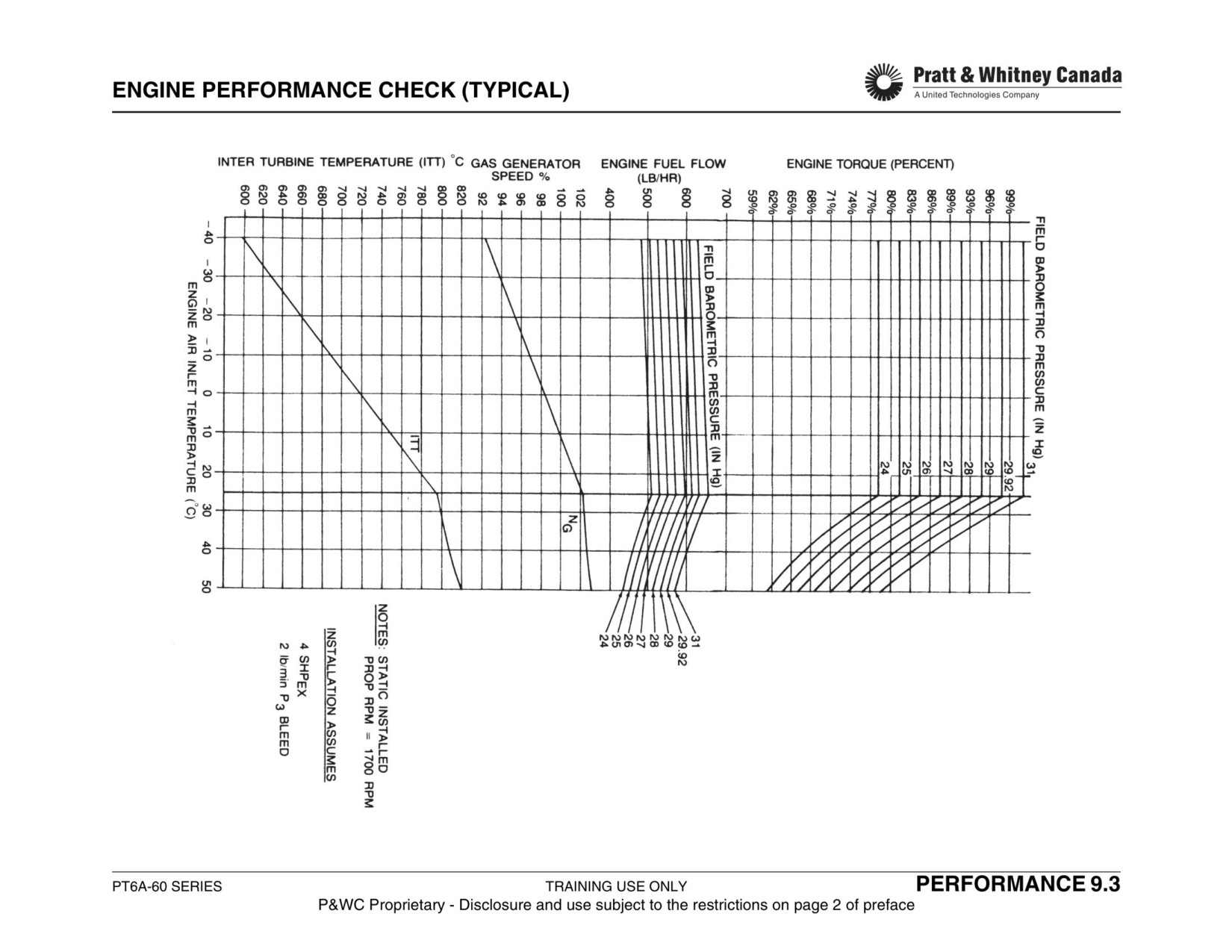
PERFORMANCE CHECK
Function:
Permits verification of engine condition over a wide range of
- From appropriate curves (Airframe M/M), determine:
ambient temperatures without exceeding torque or T5 lim-
-
Target Torque.
its.
-
ITT
-
Ng
-
Fuel Flow
Performance Check Should Be Performed:
- Determine parameter limits using tolerance from the
- After engine installation.
Airframe Maintenance Manual applied to the graph val-
- Before and after hot section inspection.
ues.
- After FCU change.
- Start engine and stabilize at idle for 5 min.
- At regular interval.
- No generator or pneumatic loads during performance
test.
- Set torque and Np as per chart.
Description:
- Stabilize engine at that power for 5 min.
- Record actual ITT, Ng and Wf.
Performance check curves establish engine parameter lim-
- Compare recorded values of ITT, Ng and Wf to chart
its for an acceptable engine at different atmospheric condi-
parameters.
tions. The check is performed at a given power where Tq
- If values deviate from chart limits, troubleshooting
and Np are constant and the values obtained for Ng, ITT
action should be undertaken to restore engine perfor-
and WF are compared to the limits obtained from the chart.
mance.
Pre-H.S.I. Checklist:
Procedure:
1. Calibrate engine gauges.
- Ensure engine indicating system is properly calibrated.
2. Check for F.O.D. and wash compressor if needed.
- Determine Outside Air Temperature (OAT).
3. Check the oil filter/screens and chip detectors.
- Determine Pressure Altitude (Pa) or Barometric Press
4. Borescope (optional)
5. Carry out a ‘before’ and ‘after’ Performance run.
-
Set altimeter to 29.92 inHg to obtain Pressure Alti-
tude
-
Set altimeter to 0 ft altitude to get field barometric
pressure
PT6A-60 SERIES
TRAINING USE ONLY
PERFORMANCE 9.2
P&WC Proprietary - Disclosure and use subject to the restrictions on page 2 of preface
PERFORMANCE CHECK (SHORTS INSTALL)
General:
Static Maximum Take Off Power Check:
Shorts installations use two types of performance checks.
A Static MTOP check is required upon replacement of an
1. Static Reduced Power Check.(Static RTOP)
engine after the Static Reduced Torque Check has been
2. Static Maximum Take Off Power check (Static MTOP)
carried-out, or if a loss of performance is noted.
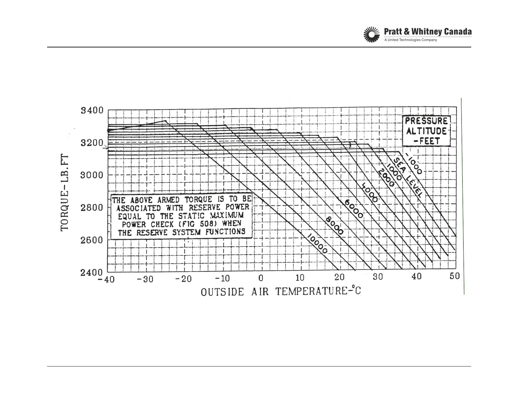
3. Reserve Power Check
1. Determine OAT and pressure altitude
Static Reduce Power Check:
2. From POH, determine target torque and corresponding
Ng, Wf and ITT target values.
This check is performed on both engines after;
3. Start and stabilize engine at target torque (1 min.)
a) installing an engine.
4. Check that observed values of Ng, Wf and ITT agree
b) a rigging adjustment.
with the graph values within tolerance.
c) a propeller or engine component change.
5. If unacceptable, refer to PWC EMM for performance
d) if requested by the flight crew.
troubleshooting flow chart.
Reserve Power Check:
Procedure:
1. Determine OAT and pressure altitude
The Reserve Power Check is a ‘follow-up’ to a satisfactory
2. From POH, determine target torque and ITT limit.
MTOP/RTOP check.
3. Start and stabilize engine at target torque (1 min.)
4. Record ITT and compare it to pre-determined limit. Must
a) Set power as per POH, (2nd engine must be at Idle/
be within POH tolerances (approx +10 / -50°C). If out of
off.)
limit, carry-out a Static MTOP check.
b) Activate Power Reserve Switch, confirm Static MTOP is
achieved.
PT6A-60 SERIES
TRAINING USE ONLY
PERFORMANCE 9.4
P&WC Proprietary - Disclosure and use subject to the restrictions on page 2 of preface
PERFORMANCE CHECK (SHORTS INSTALL)
PT6A-60 SERIES
TRAINING USE ONLY
PERFORMANCE 9.5
P&WC Proprietary - Disclosure and use subject to the restrictions on page 2 of preface
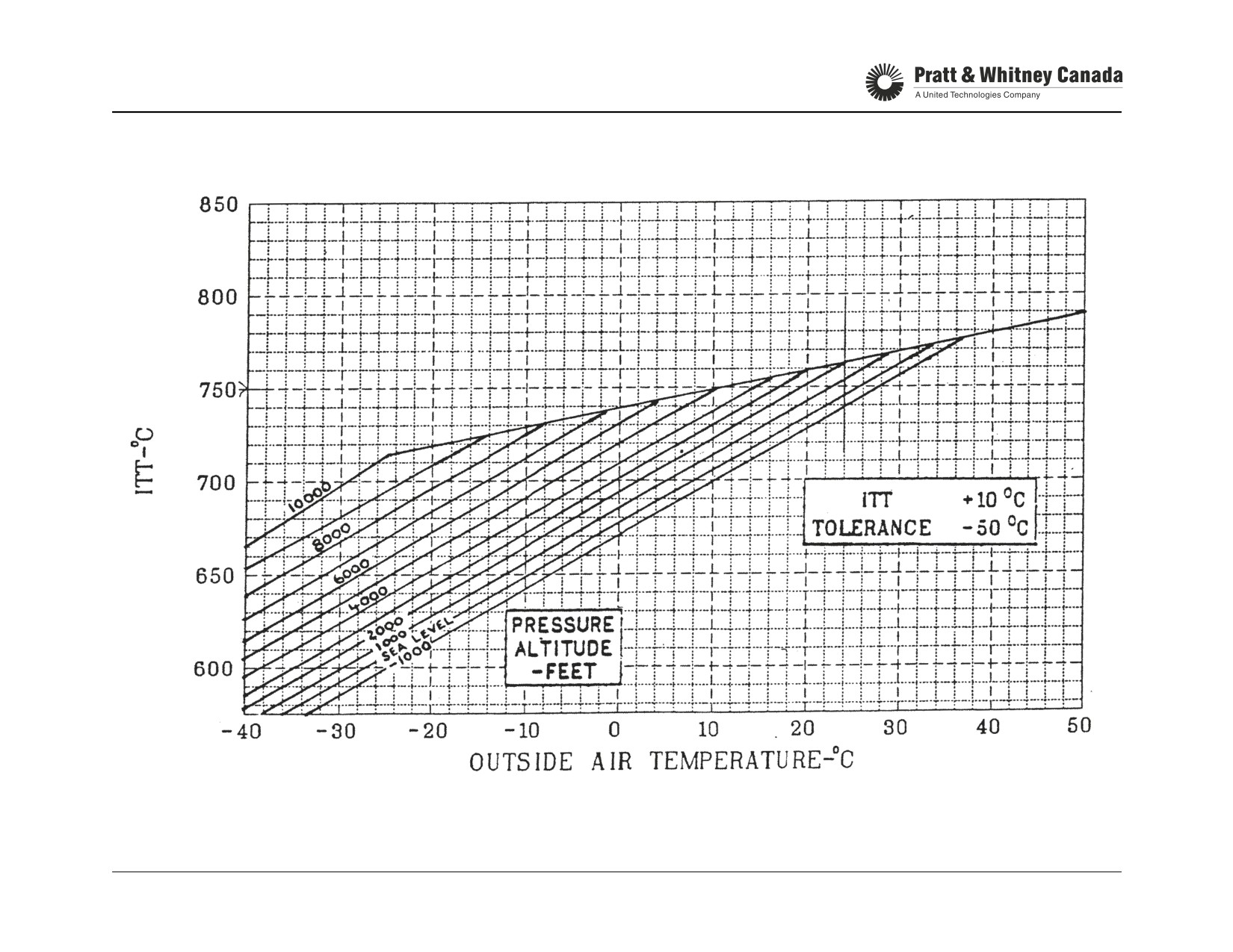
PERFORMANCE CHECK (SHORTS INSTALL)
PT6A-60 SERIES
TRAINING USE ONLY
PERFORMANCE 9.6
P&WC Proprietary - Disclosure and use subject to the restrictions on page 2 of preface
ENGINE CONDITION TREND MONITORING (WEBECTM)
Function:
Data Acquisition:
- Maintenance tool
The accuracy of the WebECTM process depends on the
- Allows user to monitor the engine performance
quality of the data entered into a computer system. Cruise
- Permits early detection of engine deterioration
condition is the only flight configuration where engine reac-
- Helps determine trouble area
tion can be predicted.
- Increase dispatch reliability
- Allows to perform repairs at the most economical time
To ensure validity of WebECTM data:
- Allows to be on (soft time) for hot section inspection
- Record data once per day, or every 6 hours
Description:
- Select the flight with the longest cruise that is at a rep-
resentative altitude and airspeed
WebECTM is a process of periodically recording engine
- Allow the engine to stabilize 3 to 5 minutes without
and aircraft instrument parameters and comparing them to
ANY power lever movements
a computer reference model.
- The same flight configuration must be repeated (i.e.
electrical load, bleed air extraction)
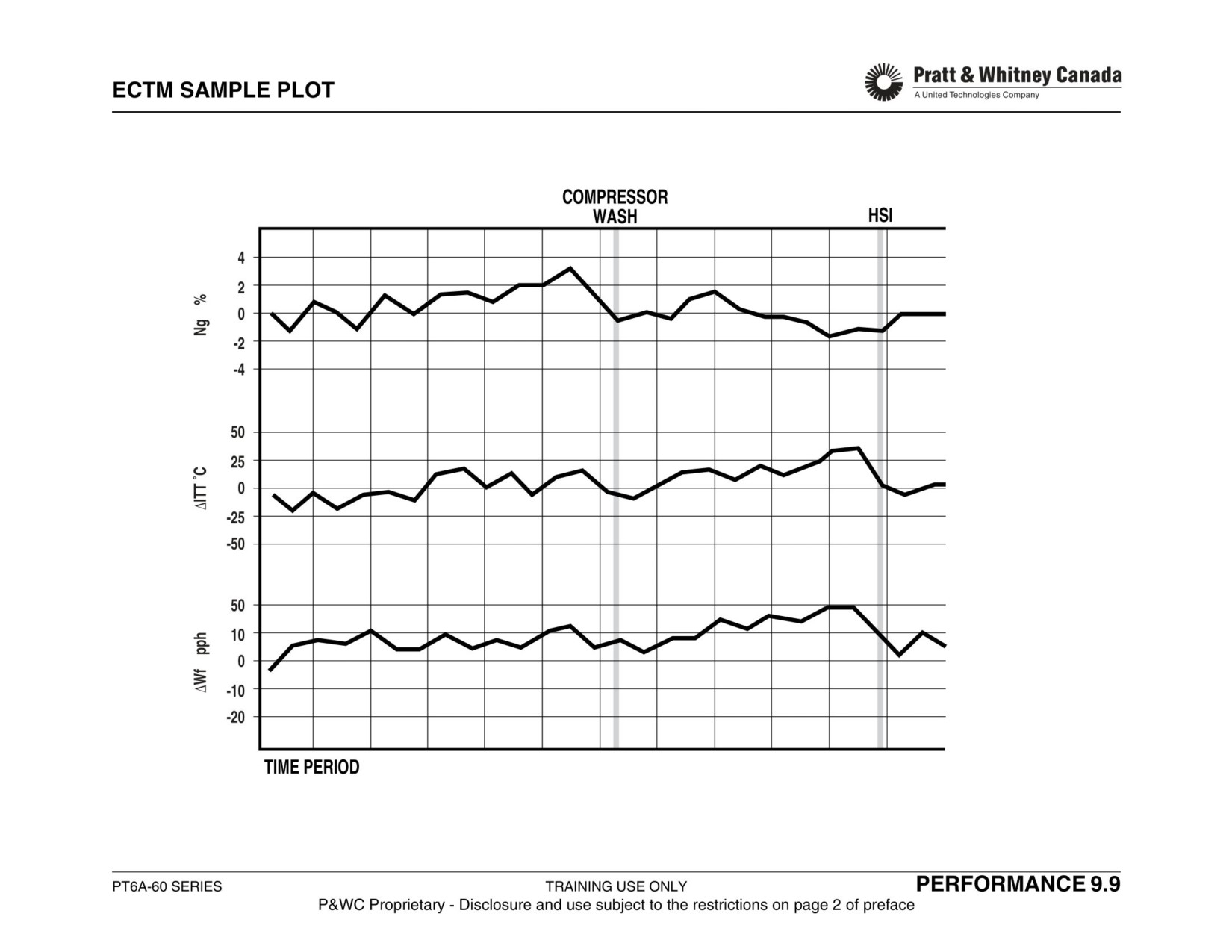
Under specific ambient conditions, engine parameters such
- Record data within a reasonable time frame
as compressor speed (Ng), Inter-turbine Temperature (ITT)
and fuel flow (Wf) are predictable. The difference between
Data entry and Calculation:
the actual engine parameters and the computer model val-
ues will be plotted as 3 deltas using a graphical chart
Via PWC WebECTM
method as illlustrated below.
Plotting and Trend Analysis:
Once a trend is established by the plotting of these deltas,
any deviation would indicate some engine deterioration.
Once the deltas are calculated, the computer does the plot-
Analysis of the trend reveals extent of deviation and possi-
ting and displays the result on screen or prints it. Analysis of
ble need for corrective action.
the trend can reveal extent of deviation and possible need
for corrective action.
PT6A-60 SERIES
TRAINING USE ONLY
PERFORMANCE 9.7
P&WC Proprietary - Disclosure and use subject to the restrictions on page 2 of preface
WEBECTM (CON’T)
Plotting:
Guidelines for interpretation of trend:
Following computation, DELTA Ng, DELTA ITT, and DELTA
Wf should be plotted on a continuous sheet. Flight log
Net change of 10 to 15°C ITT:
number may be used as the abscissa, although the trend
Early sign of deterioration, that should be investigated when
could also be recorded as a function of date or, preferably,
convenient.
as a function of engine running time in hours.
Net change of 20 to 25°C ITT:
Deterioration becoming more serious. Further running
Definition Of Terms:
could result in replacement of high cost hot section compo-
nent. Corrective action should be taken as soon as possible
Base Line:
A straight line, derived from the average of the first 15 delta
Net change of 30°C ITT:
points for a particular engine with known conditions, which
At this level, whether or not ITT is redlined, deterioration
include a recently completed HSI, inspection of compres-
has progressed to a point where serious engine damage is
sors and a compressor wash. New or newly overhauled
imminent
engines also meet these conditions.
Net change of .75 to 1% Ng:
Net Change:
Early signal of some deterioration should be investigated
The change from the base line to a line passing through a
when convenient
delta point at a specific location on the graph.
Net change over 1.5% Ng:
Revision of Base Line:
Action should be taken as soon as possible
In the event the initial base line position improperly esti-
mated, a revision of the base line values needs to be done.
Note:
A fault or change in the instrumentation calibration or an
WebECTM courses are available. Please contact P&WC
engine repair/H.S.I. will require the baseline to be re-estab-
Customer Training department for the schedule
lished.
Analysis:
The analysis of the trend graph should be carried-out on a
daily basis if possible, but not deferred for more than five
days.
PT6A-60 SERIES
TRAINING USE ONLY
PERFORMANCE 9.8
P&WC Proprietary - Disclosure and use subject to the restrictions on page 2 of preface
TBO AND HSI INTERVAL
• SB 13003 for PT6A-65
• SB 13303 for PT6A-52/60/61
Engine
TBO
H.S.I.3
• SB 13203 for PT6A-60AG, A-65AG
• SB 14003 for PT6A-67R, 67D
PT6A-52/60/61
3600
1800
• SB 14303 for PT6A-67AF, F
PT6A-65
6000
12002/20001
• SB 14603 for PT6A-64, 66, 66A/B/D, 67, 67A/B/P/T
• SB 14503 for PT6A-67AG
PT6A-64/66/66A/66D/67/67A/67T
3000
1500
PT6A-67B/P, PT6A-64 ( post SB
3500
1750 to 2000
TBO Industry:
14089 or 14112 and 14261, 14308 )
Initial TBO applicable to all operators.
PT6A-66B, PT6A-66 ( post SB
3600
1800 to 2000
14112, 14274 and Piaggio Post-
TBO Fleet:
SB80-0194 )
TBO attained by individual operators for engines of the
same model in their fleet only.
PT6A-60AG/65AG/67AF/67AG/F
3000
1500
PT6A-67D/R
6000
2000
TBO Extension:
1) A65’s operated as airliners.
Operators desiring TBO extension can submit a formal
2) A65’s operated as executive transports.
request in writing together with details of sample engine log
3) N/A if operated under an approved WebECTM program
book to: Manager, Technical Support, PT6 engines.
HSI interval may be based on engine condition trend moni-
Recommendations for time between-overhaul take into con-
toring with borescope inspection at 2000 hours and every
sideration the average effect of the many variables that
500 hours subsequently. (Ref SB 14003).
affect overhaul life. These variables are average flight dura-
tion, percentage of time at any given power level, climatic
Modular Concept:
conditions and environment, maintenance practices and
An engine may be operated as 2 distinct modules, each
engine utilization.
having a logbook. This allows an operator to return the
power section or gas generator for repair (or overhaul) and
Under extreme conditions of very low utilization coupled
keep the remaining module in service. Any spare module of
with continuous operation in salt water atmosphere or
the same model can be installed and operated as long as
heavy sand environment periodic inspections in accordance
each logbook reflects the applicable data.
with the applicable maintenance instructions may indicate
that maintenance actions are required prior to the recom-
mended overhaul life.
PT6A-60 SERIES
TRAINING USE ONLY
PERFORMANCE 9.10
P&WC Proprietary - Disclosure and use subject to the restrictions on page 2 of preface
OPERATING LIMITS*
Description:
Operating limits define the upper and lower boundaries for
all engine parameters observed in the cockpit during nor-
mal operation for each specific engine model.
Excursion beyond these limits may accelerate engine wear
and possibly lead to component malfunction.
For current operating limits, refer to applicable aircraft pilot
operating handbook.
*Operating limits, listed here, are for reference only. They
can be found in each Maintenance Manual in Section 71-
00-00.
PT6A-60 SERIES
TRAINING USE ONLY
PERFORMANCE 9.11
P&WC Proprietary - Disclosure and use subject to the restrictions on page 2 of preface
OPERATING LIMITS
PT6A-52
Power Setting
SHP
Torque
Max ITT
Ng
NP
Oil Pressure
Oil Temp.
lb-ft
psig
°C
RPM
%
RPM
PSI
°C
Take-off/Max Cont
850
2230
72.95
820
39000
104
2000
90 to 135
0 to 110
Max Climb
850
2230
72.95
775
39000
104
2000
90 to 135
0 to 110
Max. Cruise
850
2230
72.95
800
39000
104
2000
90 to 135
10 to 99
Normal Cruise
850
2230
72.95
775
39000
104
2000
90 to 135
10 to 99
Min. Idle
-
-
-
750
21000
51
-
-
-40 to +110
Starting
-
-
-
1000
-
-
-
200 (max)
-40 (min)
Transient
-
2750
89.73
850
39000
104
2205
40 to 200
0 to 110
Max. Reverse
800
-
-
760
-
-
-
90 to 135
0 to 99
PT6A-60A
Power Setting
SHP
Torque
Max ITT
Ng
NP
Oil Pressure
Oil Temp.
lb-ft
psig
°C
RPM
%
RPM
PSI
°C
Take-off
1050
3625
43.34
820
39000
104
1700
90 - 135
0 - 110
Maximum Continuous
1050
3625
43.34
820
39000
104
1700
90 - 135
0 - 110
Takeoff / Climb
1000
3625
43.34
785
39000
104
1700
90 - 135
0 - 110
Max. Cruise
1000
3625
43.34
820
39000
104
1700
90 - 135
0 - 110
Normal Cruise
1000
3625
43.34
775
39000
104
1700
90 - 135
10 - 99
Min. Idle
-
-
-
750
19000
51
-
60 (min)
-40 - 110
Starting
-
-
-
1000
-
-
-
200 (max)
-40 (min)
Transient
-
-
-
850
39000
104
1870
40 - 200
-40 - 110
Max. Reverse
900
-
-
760
-
-
1650
90 - 135
0 - 99
PT6A-60AG
Power Setting
SHP
Torque
Max ITT
Ng
NP
Oil Pressure
Oil Temp.
lb-ft
psig
°C
RPM
%
RPM
PSI
°C
Take-off
1050
3625
43.34
820
39000
104
1700
90 - 135
0 - 110
Maximum Continuous
1050
3625
43.34
775
39000
104
1700
90 - 135
0 - 110
Takeoff / Climb
1050
3625
43.34
775
39000
104
1700
90 - 135
0 - 110
Max. Cruise
1050
3625
43.34
775
39000
104
1700
90 - 135
0 - 110
Min. Idle
-
-
-
750
21750
58
-
60 (min)
-40 - 110
Starting
-
-
-
1000
-
-
-
200 (max)
-40 (min)
Transient
-
-
-
850
39000
104
1870
40 - 200
0 - 110
Max. Reverse
900
-
-
760
-
-
1650
100 - 135
0 - 104
PT6A-60 SERIES
TRAINING USE ONLY
PERFORMANCE 9.12
P&WC Proprietary - Disclosure and use subject to the restrictions on page 2 of preface
OPERATING LIMITS
PT6A-61
Power Setting
SHP
Torque
Max ITT
Ng
NP
Oil Pressure
Oil Temp.
lb-ft
psig
°C
RPM
%
RPM
PSI
°C
Take-off/Max Cont.
850
2230
72.95
800
39000
104
2000
90 - 135
0 - 110
Max. Cruise
850
2230
72.95
800
39000
104
2000
90 - 135
10 - 104
Normal Cruise
850
2230
72.95
775
39000
104
2000
90 - 135
0 - 99
Max Climb
850
2230
72.95
775
39000
104
2000
90 - 135
0 - 104
Min. Idle
-
-
-
715
19000
51
-
60 (min)
-40 - 110
Starting
-
-
-
1000
-
-
-
200 (max)
-40 (min)
Transient
-
2750
89.73
850
39000
104
2250
40 - 200
0 - 110
Max. Reverse
800
-
-
760
-
-
-
90 - 135
0 - 99
PT6A-64
Power Setting
SHP
Torque
Max ITT
Ng
NP
Oil Pressure
Oil Temp.
lb-ft
psig
°C
RPM
%
RPM
PSI
°C
Take-off
700
2230
72.95
800
39000
104
2000(90.7%)
100 - 135
0 - 110
Max. Continuous
700
2230
72.95
800
39000
104
2000
100 - 135
0 - 104
MaxClimb/Cruise
700
2230
72.95
785
39000
104
2000
100 - 135
10 - 104
Min. Idle
-
-
-
715
19000
51
-
60 (min)
-40 - 110
Starting
-
-
-
1000
-
-
-
200 (max)
-40 (min)
Transient
-
2750
89.96
870
39000
104
2205(100%)
40 - 200
-40 - 110
Max. Reverse
700
-
-
760
-
-
1900
100 - 135
0 - 104
PT6A-60 SERIES
TRAINING USE ONLY
PERFORMANCE 9.13
P&WC Proprietary - Disclosure and use subject to the restrictions on page 2 of preface
OPERATING LIMITS
PT6A-65B
Power Setting
SHP
Torque
Max ITT
Ng
NP
Oil Pressure
Oil Temp.
@ OAT
lb-ft
°C
RPM
%
RPM
PSI
°C
Take-off
1100
3625
43.34
820
39,000
104
1700
90 to 135
0 to 110
Maximum Continuous
1100
3625
43.34
810
39,000
104
1700
90 to 135
0 to 110
Maximum Climb
1000
3625
43.34
800
39,000
104
1700
90 to 135
0 to 110
Norm cruise
1000
3625
43.34
750
39,000
104
1700/100%
90 to 135
10 to 99
Min. Idle
-
-
700
21,750
58
-
60 minimum
-40 to 110
Starting
-
-
1000
-
-
-
200 max
-40 minimum
Transient
5100
870
39,000
104
1870/110%
40 to 200
0 to 110
Max. Reverse
900
-
760
-
-
1650/97%
90 to 135
0 to 99
PT6A-65AR
Power Setting
SHP
Torque
Max ITT
Ng
NP
Oil Pressure
Oil Temp.
lb-ft
°C
RPM
%
RPM
PSI
°C
Take-off
1424
4400
52.61
855
39,000
104
1700/100%
90 to 135
10 to 110
Maximum Continuous
1220
3825
45.74
840
39,000
104
1700
90 to 135
10 to 110
Maximum Cruise/
956
3625
43.34
770
39,000
104
1700
90 to 135
10 to 105
climb
Min. Idle
-
-
-
715
21,000
56
-
60 minimum
-40 to 110
Starting
-
-
-
1000
-
-
-
200 max
-40 minimum
Transient
5100
61.00
870
39,000
104
1870/110%
40 to 200
-40 to 110
Max. Reverse
900
-
-
760
-
-
1650/97%
90 to 135
10 to 105
PT6A-60 SERIES
TRAINING USE ONLY
PERFORMANCE 9.14
P&WC Proprietary - Disclosure and use subject to the restrictions on page 2 of preface
OPERATING LIMITS
PT6A-65AG
Power Setting
SHP
Torque
Max ITT
Ng
NP
Oil Pressure
Oil Temp.
lb-ft
°C
RPM
%
RPM
PSI
°C
Take-off
1300
4017
48.03
810
39,000
104
1700/100%
90 to 135
0 to 110
Maximum Continuous
1220
3825
45.74
810
39,000
104
1700
90 to 135
0 to 110
Maximum Cruise/
956
3625
43.34
800
39,000
104
1700
90 to 135
0 to 110
climb
Min. Idle
-
-
-
750
21,000
56
-
60 minimum
-40 to 110
Starting
-
-
-
1000
-
-
-
200 max
-40 minimum
Transient
5100
60.98
870
39,000
104
1870/110%
40 to 200
-40 to 110
Max. Reverse
900
-
-
760
-
-
1650/97%
90 to 135
10 to 110
PT6A-66A
Power Setting
SHP
Torque
Max ITT
Ng
NP
Oil Pressure
Oil Temp.
lb-ft
°C
RPM
%
RPM
PSI
°C
Take-off
850
2230
60.21(72.95)
830(800)
39,000
104
2000/90.7%
90 to 135
0 to 104
Maximum Continuous
850
2230
60.21(72.95)
830(800)
39,000
104
2000
90 to 135
0 to 104
Maximum Cruise/
850
2230
60.21(72.95)
820(785)
39,000
104
2000
90 to 135
0 to 104
climb
Min. Idle
-
-
-
750(759)
19,000
51
-
60 minimum
-40 to 110
Starting
-
-
-
1000
-
-
-
200 max
-40 minimum
Transient
2750
74.24(89.96)
870
39,000
104
2205/100%
40 to 200
0 to 110
Max. Reverse
800
-
-
760
-
-
1900/86.2%
90 to 135
0 to 104
PT6A-66D
Power Setting
SHP
Torque
Max ITT
Ng
NP
Oil Pressure
Oil Temp.
lb-ft
°C
RPM
%
RPM
%
PSI
°C
Take-off
850
2230
72.95
850
39,000
104
2000
90.7
100 to 135
0 to 104
Maximum Continuous
850
2230
72.95
840
39,000
104
2000
90.7
100 to 135
0 to 104
Maximum Cruise/
850
2230
72.95
840
39,000
104
2000
90.7
100 to 135
0 to 104
climb
Min. Idle
-
-
-
750
19,000
51
-
60 minimum
-40 to 110
Starting
-
-
-
1000
-
-
-
200 max
-40 minimum
Transient
2750
90.0
870
39,000
104
2205
100
40 to 200
0 to 110
Max. Reverse
800
-
-
780
-
-
1900
86.2
100 to 135
0 to 104
PT6A-60 SERIES
TRAINING USE ONLY
PERFORMANCE 9.15
P&WC Proprietary - Disclosure and use subject to the restrictions on page 2 of preface
OPERATING LIMITS
PT6A-67A
Power Setting
SHP
Torque
Max ITT
Ng
NP
Oil Pressure
Oil Temp.
lb-ft
°C
RPM
%
RPM
PSI
°C
Take-off
1200
3708
44.34
850
39,000
104
1700/100%
90 to 135
10 to 110
Max Cont
1200
3708
44.34
840
39,000
104
1700
90 to 135
10 to 110
Max. Cruise / Climb
1000
3625
43.35
840
39,000
1700
90 to 135
10 to 105
Norm Cruise / Climb
1000
3625
43.35
820
39,000
1700
90 to 135
10 to 105
Min. Idle
-
-
-
750
19,000
51
-
60 minimum
-40 to 110
Starting
-
-
-
1000
-
-
-
200 max
-40 minimum
Transient
5100
60.98
870
39,000
104
1870/110%
40 to 200
0 to 110
Max. Reverse
900
-
-
760
-
-
1650/97%
90 to 135
10 to 105
PT6A-67AG
Power Setting
SHP
Torque
Max ITT
Ng
NP
Oil Pressure
Oil Temp.
lb-ft
°C
RPM
%
RPM
PSI
°C
Take-off
1350
4170
49.87
800
39,000
104
1700/100%
90 to 135
10 to 110
Max Cont/ Cruise/
1220
3770
45.07
800
39,000
104
1700
90 to 135
10 to 110
climb
Min. Idle
-
-
-
750
19,000
51
-
60 minimum
-40 to 110
Starting
-
-
-
1000
-
-
-
200 max
-40 minimum
Transient
5100
60.98
870
39,000
104
1870/110%
40 to 200
0 to 110
Max. Reverse
900
-
-
760
-
-
1650/97%
90 to 135
10 to 105
PT6A-60 SERIES
TRAINING USE ONLY
PERFORMANCE 9.16
P&WC Proprietary - Disclosure and use subject to the restrictions on page 2 of preface
OPERATING LIMITS
PT6A-67B
Power Setting
SHP
Torque
Max ITT
Ng
NP
Oil Pressure
Oil Temp.
lb-ft
psig
°C
RPM
%
RPM
psig
°C
Take-off
1200
3708
44.34
800
39000
104
1700/100%
90 to 135
10 to 110
Maximum Continuous
1200
3708
44.34
800
39000
104
1700
90 to 135
10 to 110
Maximum Cruise/
1000
3090
36.95
760
39000
104
1700
90 to 135
10 to 110
climb
Min. Idle
750
19000
51
-
60 min.
-40 to 110
Starting
1000
-
200 max.
-40 min.
Transient
5100
61.00
870
39000
104
1870/110%
40 to 200
0 to 110
Max. Reverse
900
760
1650/97%
90 to 135
10 to 105
PT6A-67D
Power Setting
SHP
Torque
Max ITT
Ng
NP
Oil Pressure
Oil Temp.
lb-ft
psig
°C
RPM
%
RPM
psig
°C
Take-off
1279
3950
47.23
800
39000
104
1700/100%
90 to 135
10 to 110
Maximum Continuous
1214
3750
44.84
780
39000
104
1700
90 to 135
10 to 110
Maximum Cruise/
1106
3750
44.84
760
39000
104
1700
90 to 135
10 to 110
climb
Min. Idle
750
19000
51
-
60 min.
-40 to 110
Starting
1000
-
-
-
200 max.
-40 min.
Transient
5100
61.00
870
39000
104-
1870/110%
40 to 200
-40 to 110
Max. Reverse
900
760
-
1650/97%
90 to 135
10 to 105
PT6A-67F
Power Setting
SHP
Torque
Max ITT
Ng
NP
Oil Pressure
Oil Temp.
lb-ft
psig
°C
RPM
%
RPM
psig
°C
Take-off
1600
4943
60.25
870
39000
104
1700/100%
90 to 135
10 to 110
Maximum Continuous
1600
4943
60.25
870
39000
104
1700/100%
90 to 135
10 to 110
Maximum Climb/
1550
4789
58.37
815
39000
104
1700/100%
90 to 135
10 to 110
Cruise
1350
4634
56.48
795
Min. Idle
750
19000
50.7
-
60 min.
-40 to 110
Starting
1000
-
-
-
200 max.
-40 min.
Transient
6092
74.25
910
39000
104-
1870/110%
40 to 200
-40 to 110
Max. Reverse
900
760
-
1650/97%
90 to 135
10 to 105
PT6A-60 SERIES
TRAINING USE ONLY
PERFORMANCE 9.17
P&WC Proprietary - Disclosure and use subject to the restrictions on page 2 of preface
OPERATING LIMITS
PT6A-67P
Power Setting
SHP
Torque
Max ITT
Ng
NP
Oil Pressure
Oil Temp.
lb-ft
psig
°C
RPM
%
RPM
psig
°C
Take-off
1200
3708
44.34
850
39000
104
1700/100%
90 to 135
10 to 110
Maximum Continuous
1200
3708
44.34
840
39000
104
1700/100%
90 to 135
10 to 105
Maximum Climb/
1200
3708
44.34
820
39000
104
1700/100%
90 to 135
10 to 105
Cruise
1000
3090
36.95
820
Min. Idle
750
19000
51
-
60 min.
-40 to 110
Starting
1000
-
-
-
200 max.
-40 min.
Transient
5100
61.00
870
39000
104-
1870/110%
40 to 200
-40 to 110
Max. Reverse
900
760
-
1650/97%
90 to 135
10 to 105
PT6A-67R & T
Power Setting
SHP
Torque
Max ITT
Ng
NP
Oil Pressure
Oil Temp.
lb-ft
psig
°C
RPM
%
RPM
psig
°C
Take-off
1424
4400
52.61
855
39000
104
1700/100%
90 to 135
10 to 110
Alt. take-off (R only)
1281
3960
47.35
825
39000
104
1700
90 to 135
10 to 110
Maximum Continuous
1220
3825
45.74
840
39000
104
1700
90 to 135
10 to 110
Maximum Cruise/
1020
3760
44.96
790
39000
104
1425
90 to 135
10 to 105
climb
Min. Idle
-
-
755
21000
56
-
60 min
-40 to 110
Starting
-
-
1000
-
-
-
200 Max
-40 min.
Transient
5100
61.00
870
39000
104
1870/110%
40 to 200
0 to 110
Max. Reverse
900
-
-
760
-
-
1650
90 to 135
10 to 105
PT6A-60 SERIES
TRAINING USE ONLY
PERFORMANCE 9.18
P&WC Proprietary - Disclosure and use subject to the restrictions on page 2 of preface
ROTOR COMPONENTS - SERVICE LIFE
Description:
Flight Count Factor:
Certain rotating components are subject to low-cycle
This is an index of severity. An indication of how much a
fatigue due to cyclic operation of the engine. Additionally,
component is affected during the engine operation. This is
other factors such as high frequency fatigue and metallurgi-
a multiplier and will change for a given component if
cal changes related to time rather than flight cycles are con-
installed in a different engine.
sidered. As a result, these parts must be removed from
service when the cycle limit is reached.
If your missions include more flights than starts, component
cycle life may be calculated in accordance with the following
Reference:
formula:
- SB 13002 for PT6A-52/60/61/65
- SB 13202 for PT6A-65AG
Total Cycles =
- SB 14002 for PT6A-64,66,67, 67B/D/P
[Starts + ( Flights-Starts
) ] x Flight Count Factor
Abb. Cycle Factor
- SB 14302 for PT6A-67AF
- SB 14502 for PT6A-67AG/67F
Operators having missions, which include many touch-and-
go flights or a frequency of scheduled in-flight shutdowns
(such as used during pilot training) or which include more
Airworthiness Regulations Require The Operator To:
than 10 flights per hour must submit their mission profiles to
- Log engine hours, starts and aircraft flights
Pratt and Whitney Canada for life cycle analysis.
- Calculate and record these hours and cycles
Definition Of A Cycle:
A flight preceded by a start and followed by a shutdown.
Abbreviated Cycle:
A flight, from wheels up to wheels down, but without a start
or shutdown.
PT6A-60 SERIES
TRAINING USE ONLY
PERFORMANCE 9.19
P&WC Proprietary - Disclosure and use subject to the restrictions on page 2 of preface
ENGINE TROUBLESHOOTING
Effective engine troubleshooting infers monitoring engine
Troubleshooting of problems related to internal engine com-
parameters on a regular basis, using performance check
ponents is generally divided in 2 areas:
and engine condition trend monitoring.
- Compressor section
- Hot section.
Effective troubleshooting can be divided into four steps:
The compressor section refers to all the components of the
1. Evaluate the symptoms
main gas path. This starts from the aircraft inlet and
2. Logically isolate the possible cause of the problem
includes the gas generator where P3 air fills the cavity
3. Try quick fixes when possible.
around the combustion chamber liner.
4. Determine the corrective action required to solve the
problem
The hot section is composed of all the components starting
from the combustion chamber liner down to the exhaust
Remember that troubleshooting is done by comparing
duct including all the vane rings and the turbines.
engine parameters with a set of reference values for a good
engine or by looking at the trend of the parameters of one
engine over a period of time.
Propeller speed and torque are the indication of power pro-
duced by an engine. Any serious troubleshooting should
begin with the calibration of the instruments used in the pro-
cess.
Note:
Chapters 10 and 11 cover troubleshooting of fuel and pro-
peller systems.
PT6A-60 SERIES
TRAINING USE ONLY
PERFORMANCE 9.22
P&WC Proprietary - Disclosure and use subject to the restrictions on page 2 of preface
PERFORMANCE TROUBLESHOOTING
Introduction:
Systematic Approach:
- The following information is a guide only.
- Preferred approach
- Refer to the appropriate aircraft or engine mainte-
- Gathering of all applicable information
nance manual as necessary.
- Analysis of engine symptoms
- Determination of most probable cause
- Corrective actions
Troubleshooting:
- Confirm results
- Technique used to logically isolate the cause of an
engine problem .
This method requires a good knowledge of normal and
- Determine the corrective maintenance action(s).
abnormal engine operation, systems operation as well as
- Resolve the problem in a timely manner.
the ability to use technical manuals efficiently.
The systematic approach increases the chances that you
Shotgun Approach:
are looking in the correct area for the problem, so that pre-
- Based on a "Trial and Error" method.
cious man-hours and material are not wasted on tasks that
- Used by personnel with minimal knowledge of engine
provide no resolution to the problem.
operation and troubleshooting techniques.
- This time consuming method is not cost effective and
indicates that some form of training is required.
By The Book Approach:
Effective but time consuming method used by maintenance
technicians who follow all necessary troubleshooting proce-
dures from technical manuals. This method requires some
knowledge of engine construction and operation.
PT6A-60 SERIES
TRAINING USE ONLY
PERFORMANCE 9.23
P&WC Proprietary - Disclosure and use subject to the restrictions on page 2 of preface
PERFORMANCE TROUBLESHOOTING (CONT’D)
The Basics:
tance limits on compressor FOD. The extended limits are
- Understand the problem
approximately double the previous ones but are acceptable
- Simultaneous review of ECTM* and recent past history
providing that engine performance remains acceptable.
- Pilot reports, and maintenance logs
Therefore, if the FOD is towards the high side of the
A review of the ECTM plots for the past three to six months
extended limits, heavy erosion is visible or the engine is
in conjunction with a review of the past thirty days of pilot
having performance difficulties then it is likely the compres-
write-ups and maintenance actions are the two most useful
sor has reached the refurbishment point. Further attempts
tools to be employed in defining the problem and setting a
to repair the engine on-wing would be futile.
plan for corrective action. It is recommended these records
be available on-site where the aircraft maintenance is being
Compressor Wash:
performed and not in a locked office a few hundred miles
- How long since last wash
away where the individual has gone home for the night. If
- Does ECTM show extended gradual shift right of all
this is not the case, then the maintenance crew should have
parameters
some way of accessing the information.
- Experience has shown 15 to 20 °C recovery when
washed
ECTM has the ability to tell you if the problem is in the cold
- A wash may be all you need
section or hot section of the engine. A step shift of only one
parameter is a likely instrumentation problem.
If it has been some time since the last wash and the com-
pressor looks dirty, it is recommended a ground perfor-
Pilot write-ups and maintenance logs can offer very valid
mance run be carried out, followed by engine wash, and
clues; for example if the pilot report has been repeated sev-
then finally by another ground performance run. A compar-
eral times dated back to seven days previous. One could
ison of the pre and post wash run data will indicate how
go back and review the maintenance actions carried out just
dirty the engine was and if any further troubleshooting is
prior to the first pilot report to see if the problem was intro-
required. We have seen reported "major performance loss"
duced by the maintenance action.
being rectified by nothing more than two successive engine
washes.
Compressor Health:
* Inspection for FOD and erosion
Note:
* Increased manual limits
ECTM = Engine Condition Trend Monitoring
* Compressor may have reached refurbishment point
One of the first areas that one should look at on the engine
is the compressor intake. PWC has extended the accep-
PT6A-60 SERIES
TRAINING USE ONLY
PERFORMANCE 9.24
P&WC Proprietary - Disclosure and use subject to the restrictions on page 2 of preface
PERFORMANCE TROUBLESHOOTING (CONT’D)
Instrument Calibration:
From the previous example, the importance of instrument
- How long since last calibration.
calibration can not be overemphasized.
- Accurate calibrations are worth the effort.
- OAT, PA, and IAS are used in normalization process
and thereby affect ECTM accuracy .
Intake Deviations:
- Erroneous OAT, PA, and TQ affects targets for the day.
- Actual running data has shown up to 35° C ITT differ-
- If ECTM data shows a step jump in ITT only, one
ential between separator deployment and retraction
should suspect an instrumentation problem in the ITT
- Ice vane drop/out of adjustment will also cause perfor-
system.
mance deterioration and parameter fluctuation
- Similarly if all parameters are high, a torque indication
problem is likely.
Eliminate Cabin Bleed Leaks:
Remember ECTM plots are produced by normalization pro-
- Ground run with cabin bleeds blanked at engine flange
cess of certain inputs and then comparing the normalized
- Compare blanked and un-blanked run data
data with actual recorded. Outside air temperature, pres-
- Leaking P3 pre-coolers and defective temp control
sure altitude, prop speed, and airspeed are inputs to the
valves have caused up to 60°C rises in ITT
normalization formula. If these parameters are out of cali-
bration, the ECTM plots will be unreliable as a trouble-
shooting tool.
Carry out a ground performance run with the cabin bleed
systems in the normal off position. Follow this with a
Outside air temperature and pressure altitude are used to
ground performance run with the bleeds blanked at the
determine target torque for the day in doing ground perfor-
engine flange. It is important to blank the system at the
mance runs. Errors in these instruments will lead to selec-
engine flange rather than at some other convenient loca-
tion of the wrong target torque for the day. If the torque
tion.
transducer calibration is low, the actual engine torque will
be higher than what is indicated. This is perceived as the
engine being temperature limited, as well, fuel flow and gas
generator speed will be higher than normal.
PT6A-60 SERIES
TRAINING USE ONLY
PERFORMANCE 9.25
P&WC Proprietary - Disclosure and use subject to the restrictions on page 2 of preface
PERFORMANCE TROUBLESHOOTING (CONT’D)
Eliminate Cabin Bleed Leaks (Cont'd):
Trim Determination:
- Trim on/off runs to determine if trim compensation is
Compare the results of the two runs. If the parameters of
correct.
the run with the bleeds blanked appear lower, you have a
- Not a "dial as required system"
leak or component malfunction in the bleed system that
- Do not readjust existing trim probes.
requires rectification.
At the same time as the bleeds blanked run is done, it is
Do two ground runs at take-off power, one with the trim
also a convenient opportunity to do a bleed valve closing
compensator connected and one with it disconnected and
point check and a T5 trim determination check.
compare the results. It is recommended to use a precision
tester (i.e. Barfield) to monitor ITT during these runs rather
Bleed Valve Closing:
than the cockpit gauge. The delta in ITT between these two
- Is the BOV closure point correct ?
runs should be within ±10% of engine data plate trim value.
- Late closing bleed valve results in high ITT.
- Sticking bleed valve results in intermittent power.
If the delta is greater than ±10%, the T5 trim compensator
- Regular scheduled BOV checks.
should be replaced. Previously installed or adjusted trim
- Closure point shifts with time.
compensators must not be readjusted.
- Some engines have classified CT baffle.
- Controls BOV closing pressure air.
- Facilitates seat adjustment.
- Mixing pre and post SB hardware results in BOV clos-
ing problems.
Some engine models have a classified baffle bolted to the
number two bearing cover. The size of the inner diameter
of this baffle controls the air to the bleed valve, therefore,
when working in this area pay particular attention not to
intermix pre and post SB hardware. Intermixing of hard-
ware results in BOV timing difficulties.
PT6A-60 SERIES
TRAINING USE ONLY
PERFORMANCE 9.26
P&WC Proprietary - Disclosure and use subject to the restrictions on page 2 of preface
PERFORMANCE TROUBLESHOOTING (CONT’D)
Borescope Inspection:
Engines are assembled; performance tested and trimmed
- Borescope engine to confirm hot section distress.
with a particular set of CT and first stage PT vane classes.
- Does what you see with the borescope agree with the
It is important to know what these classes were as a refer-
ECTM plots.
ence point for future on-wing maintenance.
- Do you want to run to extended borescope limits.
When it becomes necessary to replace a CT or Power Tur-
If the ECTM plots show typical hot section deterioration (ris-
bine (PT) vane on-wing, one must go back to the last test
ing ITT and decreasing NG) you should see distress of the
cell performance run vane class matching as a reference for
Compressor Turbine (CT) vane and/or CT blades when you
replacement, not necessarily the class that was removed.
borescope the hot section.
PWC recognize that it is not always possible to obtain the
Some maintenance manuals have the extended inspection
exact same class vane as required on short notice. To
limits incorporated (72-00-00). A number of factors must be
allow some flexibility, PWC recommends that one stays
taken into consideration when opting to run to the extended
within ±0.03 of a class on CT and ±0.1 of a class on PT of
limits. The two factors are whether there is a large ITT delta
those installed at last test cell run.
upshift in the ECTM plots and how long the engine has
been operating this way. If the borescope inspection
Maintaining a small spreadsheet for your complete fleet is a
reveals a burned through vane airfoil one must carefully
useful tool and worth the effort. The spreadsheet should
assess the decision to continue in service. As this condition
contain engine serial number with what class vanes were
excites the CT blade that can lead to blade cracking and
installed at last test cell run and what classes are currently
possible failure.
installed. It can give ready picture of what engines may not
be ideally matched. It can also speed up the process in hot
Engine Matching:
section planning.
- Has engine performance been questionable since last
HSI.
- What classes of CT and PT vanes were installed at
last test cell run.
- What vane classes are installed now.
- Use same class within ± .03 CT and ± .1 PT
- Keep a log of important engine data, BOV seat, CT
baffle, vane class etc.
PT6A-60 SERIES
TRAINING USE ONLY
PERFORMANCE 9.27
P&WC Proprietary - Disclosure and use subject to the restrictions on page 2 of preface
FUEL SYSTEM
FUEL SYSTEM
PT6A-60 SERIES
TRAINING USE ONLY
FUEL SYSTEM 10.1
P&WC Proprietary - Disclosure and use subject to the restrictions on page 2 of preface
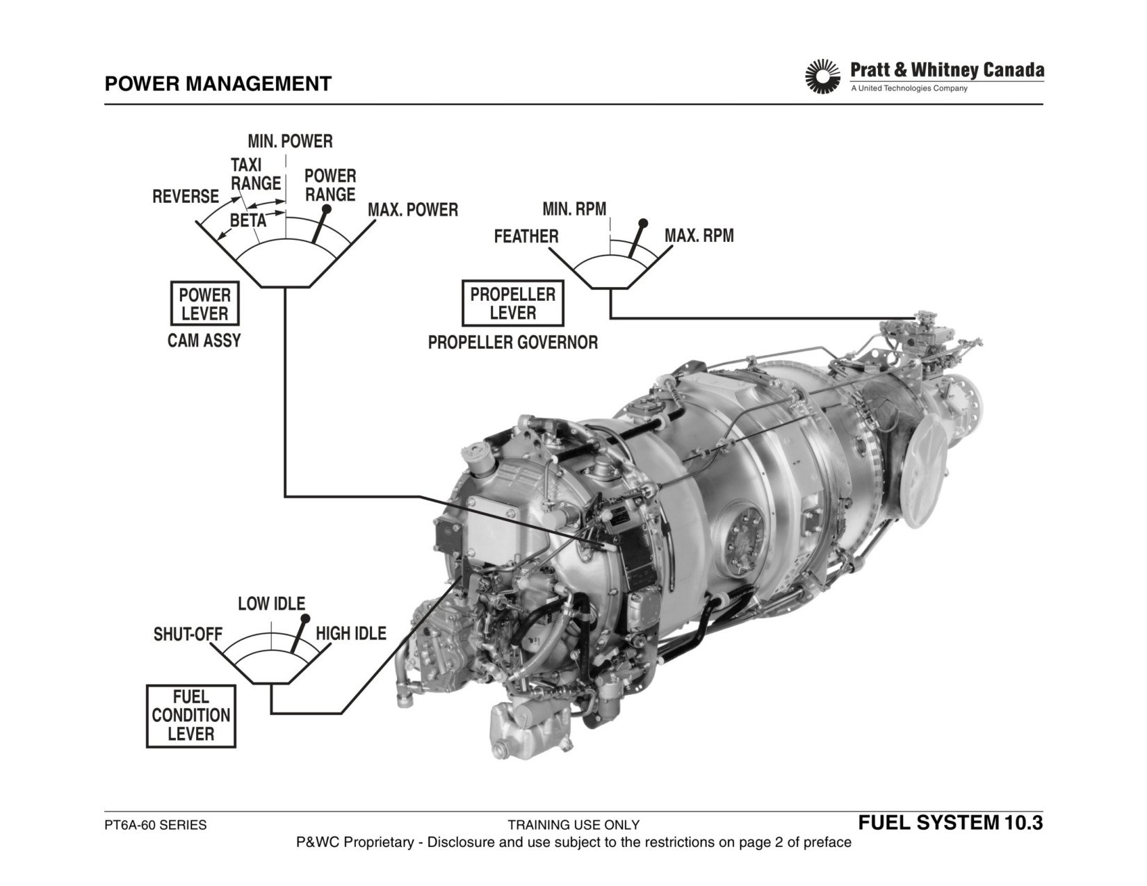
POWER MANAGEMENT
- 3 lever control system
Propeller Lever:
- 2 levers on PT6A-66 and A-67B/P
- Connected to the propeller speed control lever on the
top of the propeller governor (CSU).
Power Lever:
- Controls the propeller speed in the governing mode.
- Controls the compressor speed in forward as well as
- Allows feathering of the propeller.
reverse thrust mode.
- Controls the propeller pitch in reverse.
Manual Override (Power Lever):
- Connects to a cam cluster located on the accessory
- Single engine aircraft only.
gearbox.
- Controls Ng directly in the event of a loss of P3 air
- Cam cluster transmits power lever movement to the
pressure at the FCU.
fuel control unit.
- Controls fuel flow from minimum to maximum flow
- The FCU controls Ng.
stops.
- Used in forward mode only.
Below idle, movement of the power lever affects both Ng
and the beta valve to change the propeller blade angle from
Note:
positive pitch to reverse pitch as power is gradually
Engines operated with two levers have a ‘single speed’ pro-
increased in reverse.
peller governor. (Pilatus PC-XII aircraft PT6A-67B/P).
Fuel Lever (Condition Lever):
- Cut-off position stops fuel flow to the combustion
chamber and causes the engine to shut down
- Allows to set Ng from low idle to high idle
- Low idle is the minimum Ng allowed
- High idle is the minimum power used in flight
When the correct Ng is reached, the low idle position is
selected to allow fuel into the combustion chamber.
PT6A-60 SERIES
TRAINING USE ONLY
FUEL SYSTEM 10.2
P&WC Proprietary - Disclosure and use subject to the restrictions on page 2 of preface
FUEL SYSTEM
Function:
Alternate/Emergency Fuels:
Provides the engine with clean fuel at the required pressure
Minimize use of AVGAS. AVGAS may contribute to acceler-
and flow to permit control of engine power.
ate hot section deteriorations. Run AVGAS a maximum of
150 hrs between overhauls.
Components:
- Fuel heater
Operating time on AVGAS is computed on the basis of
- Fuel pump
quantity used versus average engine consumption. The
- Fuel control unit
operation of P&WC commercial engines, covered by this
- Flow divider
training manual, on fuel other than the approved jet fuels is
- Fuel nozzles (14)
not permitted without the express permission of P&WC.
- Fuel drain valves (2)
Fuel And Additives:
- SB 13044 for A-52/60/61/65.
- SB 13244 for A-65AG.
- SB 14004 for A-64/66/67.
- SB 14504 for A67AG/F
- SB’s indicated above list minimum requirements for
acceptable engine fuel.
- Additives such as;
-
anti-corrosion.
-
anti-icing.
-
thermal stability additives.
-
Anti-microbial
- Use of Aviation Gasoline (AVGAS) is limited to 150
hours per engine between overhaul periods (TBO).
- Diesel fuel is permitted for agricultural use only.
PT6A-60 SERIES
TRAINING USE ONLY
FUEL SYSTEM 10.4
P&WC Proprietary - Disclosure and use subject to the restrictions on page 2 of preface
FUEL SYSTEM
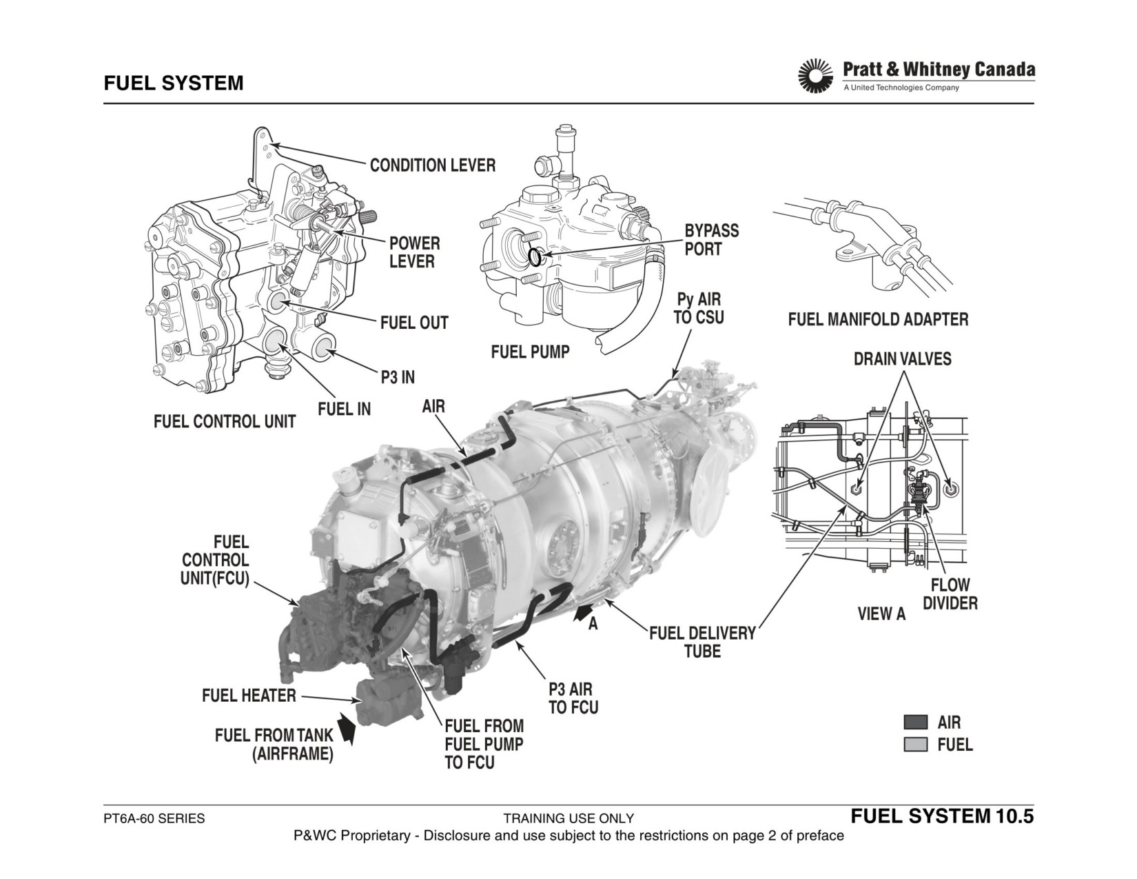
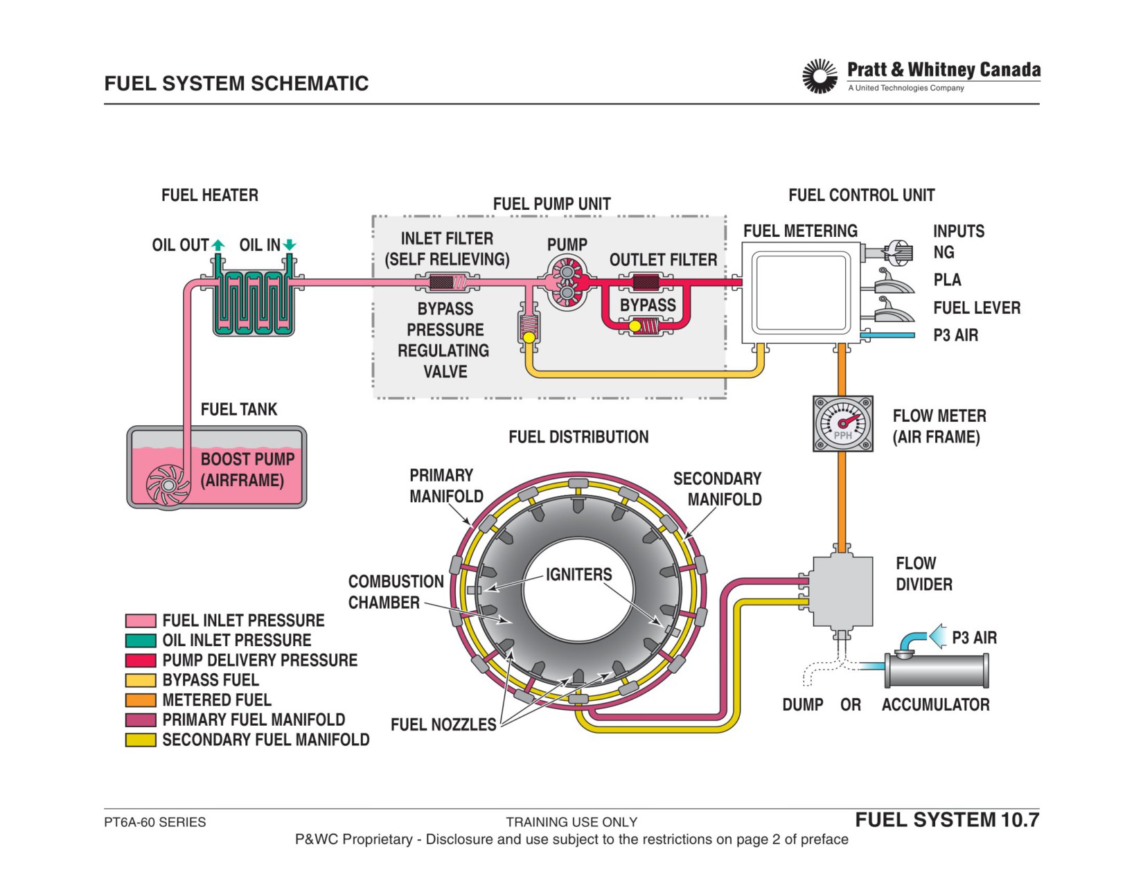
Description:
Fuel from the aircraft tank is sent to the fuel heater via one
or more airframe boost pumps. From the fuel heater, fuel is
directed to the fuel pump. The fuel pump sends the fuel to
the fuel control unit (FCU) which determines the quantity of
fuel required by the engine to produce the power requested
through the power lever and according to the ambient con-
ditions.
The excess fuel is returned to the inlet of the fuel pump and
the fuel flow going to the engine goes through the fuel flow
meter to indicate the fuel consumption in the cockpit. Then,
the fuel reaches the flow divider where it is directed to the
primary and secondary fuel manifolds to supply all the noz-
zles. The fuel nozzles atomize the fuel in the combustion
chamber to sustain the combustion.
PT6A-60 SERIES
TRAINING USE ONLY
FUEL SYSTEM 10.6
P&WC Proprietary - Disclosure and use subject to the restrictions on page 2 of preface
FUEL HEATER
Function:
Maintenance:
- Heat the fuel to prevent ice crystal formation
- Replace unit if defective.
- Heat the FCU housing to prevent condensation from
- Repair the coating on fuel heater as per engine Main-
freezing in the bellows assembly
tenance Manual.
- Preheat the fuel for FCU calibration
Troubleshooting:
Description:
- Verify operation by touching the fuel filter bowl after
- Housing
shutdown. Should be warm but not hot (≈27°C / 80°F).
- Fuel passages
- A template temperarure recorder can be used to deter-
- Scavenge oil passages
mine if thermal element is good (refer to the Mainte-
- Thermal element sensing fuel temperature
nance Manual).
- Internal damage may cause oil to mix with fuel and
result in high oil consumption when engine is running.
Operation:
- Internal damage may also cause fuel to mix with the oil
in static conditions.
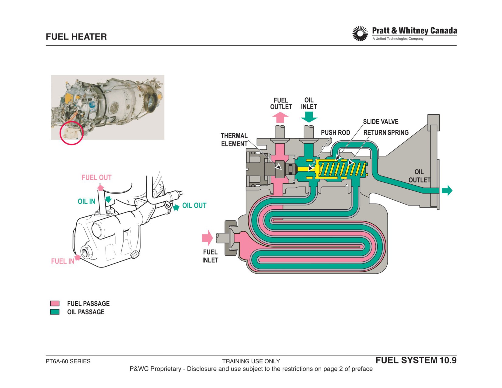
Cold fuel from the aircraft boost pump enters the fuel heater
and surrounds the thermal element. The cold thermal ele-
ment contracts and allows scavenge oil from the accessory
Symptom
Cause
Effect
gearbox to travel across the heat exchanger. Heat from the
oil transfers to the fuel raising it's temperature.
Fuel Too Hot
Thermal element or
Fuel pump
control valve
cavitation
At 21°C the thermal element begins to expand and moves
Fuel Too Cold
Thermal element or
Possible filter
the valve to the right. In this position, scavenge oil from the
control valve
blockage (ice)
accessory gearbox progressively bypasses the fuel heater
and the fuel temperature begins to stabilize. The spring
High Oil Con-
Heat exchanger
Oil leak in the
located at the back of the valve pushes it back to the left
sumption
internal leakage
fuel
(heating position) when the fuel temperature drops. During
operation, the thermal element constantly reacts to adjust
fuel outlet temperature.
PT6A-60 SERIES
TRAINING USE ONLY
FUEL SYSTEM 10.8
P&WC Proprietary - Disclosure and use subject to the restrictions on page 2 of preface
FUEL PUMP
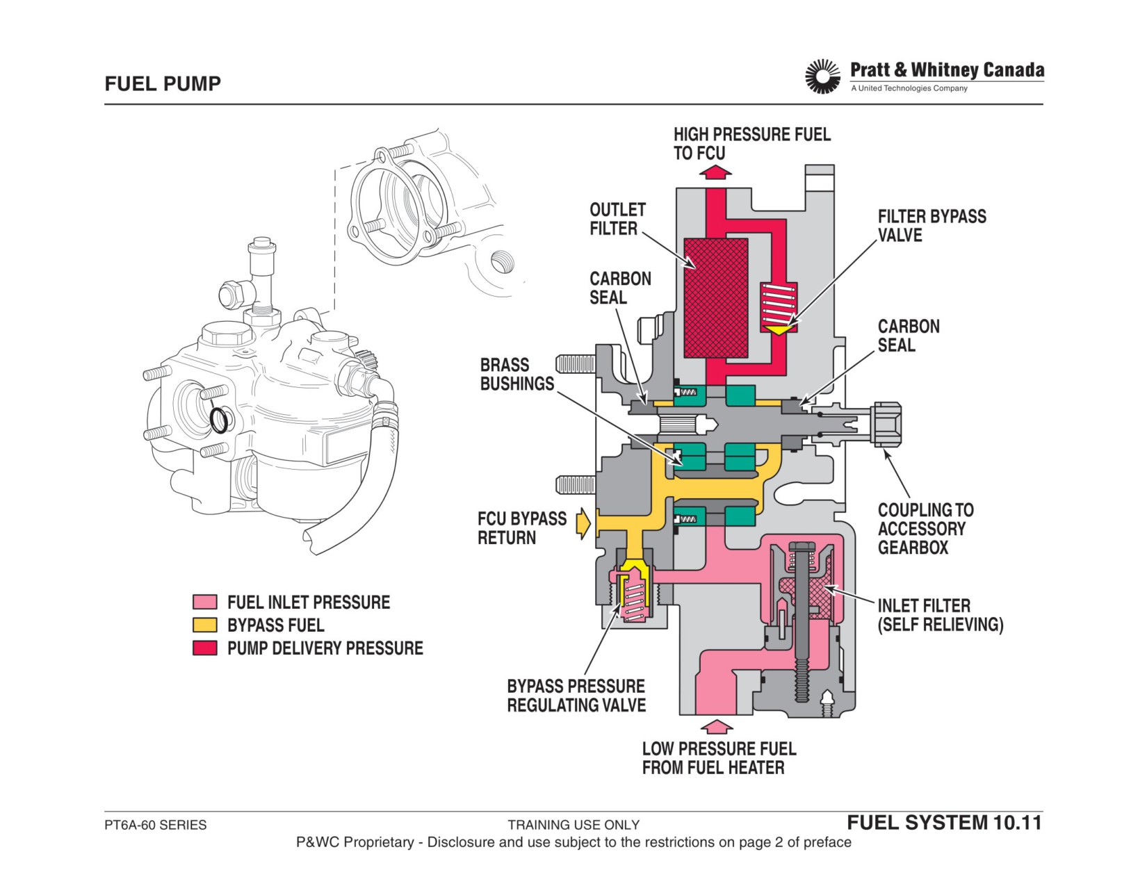
Function:
Outlet Filter Bypass Valve:
- Bypass fuel if filter gets restricted
Provide clean fuel under pressure to the fuel control unit.
- Set to open at 15-25 psid
Description:
- Single stage
Bypass Pressure Regulating Valve:
- Gear type pump
- Maintains bypass pressure above a minimum to mini-
- Brass bushings loaded against pump gears
mize fuel leakage at the brass bushing
- Carbon seals prevent fuel leak
- Set to open at 10 - 35 psid
- Inlet and outlet fuel filters
Operation:
Pump Capacity (Typical):
From the fuel heater, fuel enters the fuel pump housing and
passes through the inlet filter, then through the pump. Fuel
is filtered a second time through the outlet filter before being
Ng
Wf
Pressure
delivered to the fuel control unit. Two carbon face seals
%
pph
psi
prevent fuel from leaking out of the pump. A bypass pres-
13 %
200
175
sure regulating valve is mounted on the FCU bypass return
line to ensure a minimum amount of pressure is maintained
100 %
1600
800
on the brass bushings to reduce fuel leakage when pump
Typical engine Wf at 1000 SHP ≈ 500 pph
pressure increases.
Inlet Filter:
Maintenance:
- 74 micron screen.
- Inspect inlet and outlet filters at specified intervals.
- Cleanable (600hrs)
- Inspect for reddish-brown stain in drain port of fuel
- Bypass feature
pump (Sundstrand pumps only).
- Bypass at 1.5 psid
- Replace fuel pump if the engine is operated without
airframe boost pressure for more than 10 hours.
Outlet Filter:
- 10 micron non-metallic type filter
- Disposable (600hrs)
PT6A-60 SERIES
TRAINING USE ONLY
FUEL SYSTEM 10.10
P&WC Proprietary - Disclosure and use subject to the restrictions on page 2 of preface
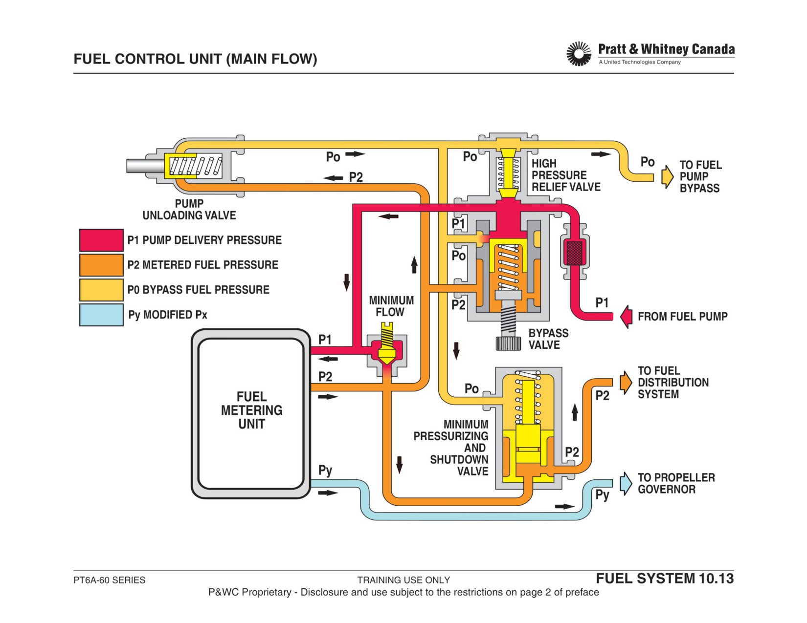
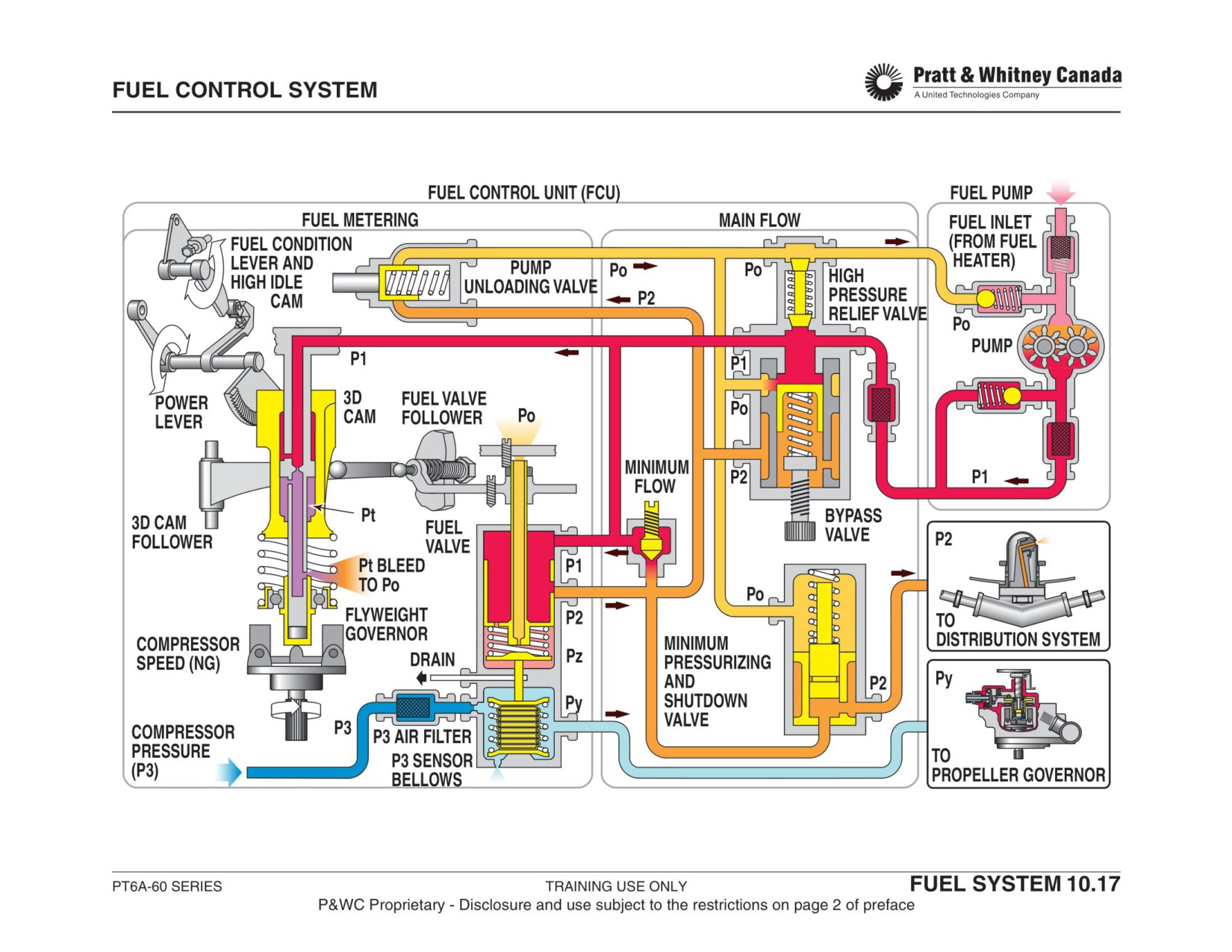
FUEL CONTROL UNIT (MAIN FLOW)
Function:
Minimum Flow:
- Provides minimum fuel to start engine and prevents
Deliver the required amount of fuel at the required pressure
flame out during rapid deceleration
to the fuel nozzles.
- Factory set at ≈90 pph
Pressure Relief Valve:
Pump Unloading Valve:
- Prevents system over pressurization
- Pilot operated to start or shutdown the engine
- Dumps excess fuel to the bypass
- Opens when pilot shuts down the engine
- Factory set to open at 1350 psid
- Dumps P2 fuel to P0
- P2 becomes equal to P0
- Shutdown valve closes
Bypass Valve:
- Factory set
- Maintains delta pressure P1-P2 constant at 53 psid
- Bypass fuel in excess of engine requirement
- Fuel pump delivers more fuel than required
Minimum Pressurizing And Shutdown Valve:
- Bypass fuel returns to the pump
- Allows the fuel control to pressurize before providing
- Factory adjusted to limit engine acceleration rate
fuel to the engine
- Improves fuel metering on start
During acceleration, more fuel is required in the P2 line. To
- Works in conjunction with the pump unloading valve
supply the need, less fuel is dumped to Po by the bypass
for engine shut down
valve. During deceleration, the opposite applies.
- Opens at 100 psid
PT6A-60 SERIES
TRAINING USE ONLY
FUEL SYSTEM 10.12
P&WC Proprietary - Disclosure and use subject to the restrictions on page 2 of preface
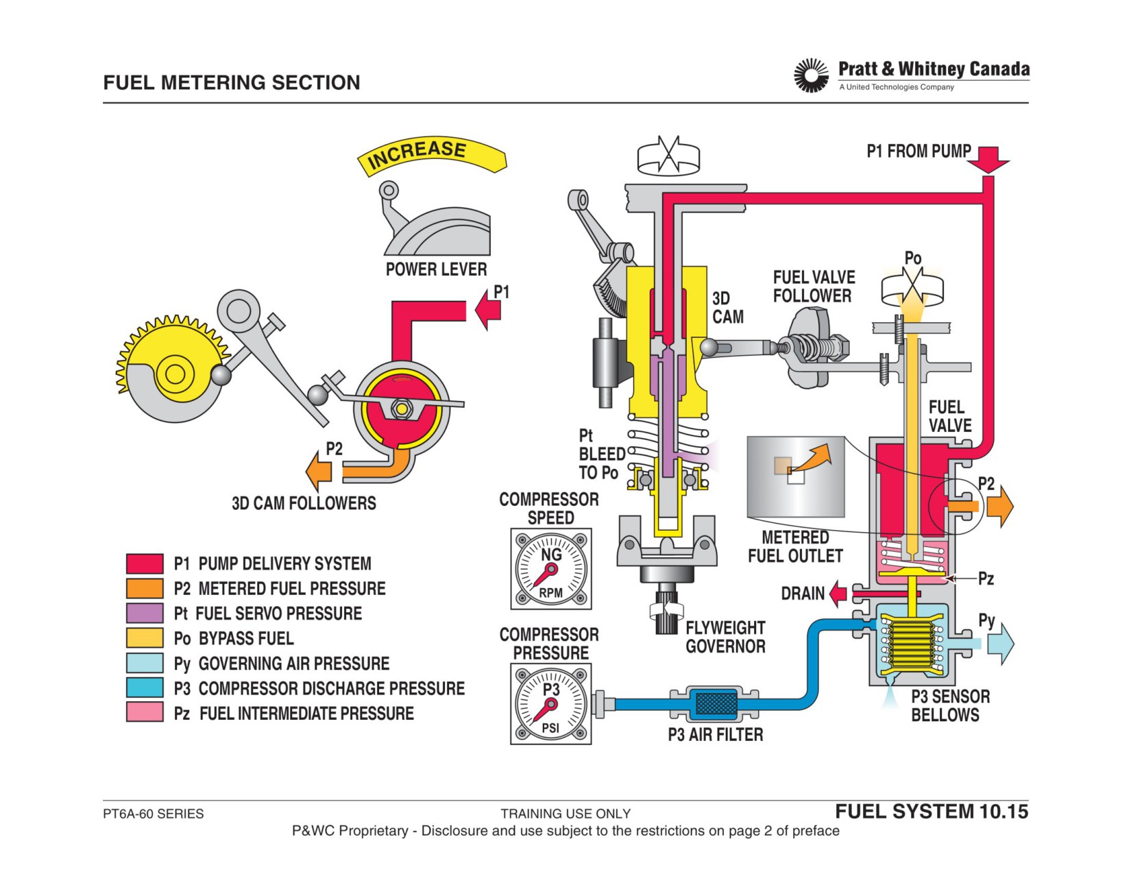
FUEL CONTROL UNIT (METERING)
Function:
Fuel Valve And Bellows Section:
Determines fuel flow to the engine in response to the follow-
The Fuel Valve rotates and moves up and down to deter-
ing inputs:
mine the amount of fuel going to the engine by varying the
- Power Lever Position (PLA)
opening between the inner rotating valve and the static
- Compressor discharge pressure (P3)
outer valve.
- Compressor speed (Ng)
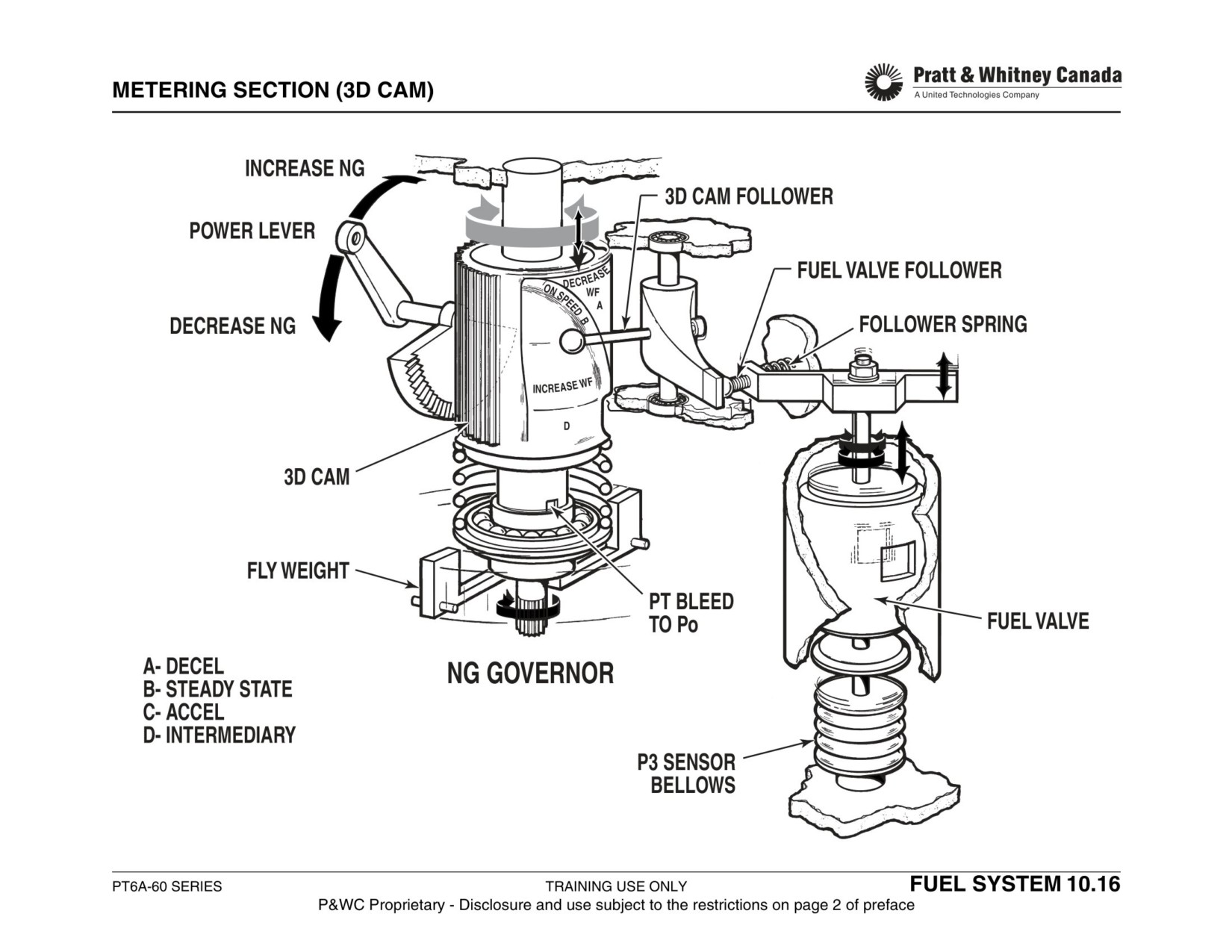
Cockpit movement of the PLA causes the 3D cam to rotate.
Rotation of the 3D cam makes the Cam Follower move
3D Cam And Follower:
which in turn rotates the Fuel Valve (Initial accel or decel).
Rotates around it's centerline and up and down in response
Up and down movement of the Fuel Valve depends on the
to power lever movement and compressor speed (Ng). The
bellows position (P3 air pressure).
3D cam is rotated by moving the power lever in the cockpit.
The face of the cam is shaped to move the cam follower and
- More Wf
rotate the fuel valve, thus changing fuel flow and Ng.
Increasing P3 moves the Valve Seat down, allowing Pz
pressure to diminish, resulting in a downward movement of
The 3D cam also senses Ng speed via a flyweight governor.
the Fuel Valve.
Variation of Ng speed causes the Po orifice to open or close
causing the 3D cam to translate up or down. The cam fol-
- Less Wf
lower and fuel valve move in response to the 3D cam there-
Decreasing P3 moves the Valve Seat up, allowing Pz pres-
fore changing fuel flow and Ng.
sure to increase, resulting in an upward movement of the
Fuel Valve.
PT6A-60 SERIES
TRAINING USE ONLY
FUEL SYSTEM 10.14
P&WC Proprietary - Disclosure and use subject to the restrictions on page 2 of preface
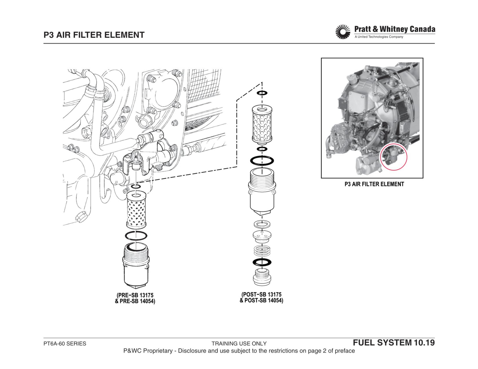
COMPRESSOR DELEVERY AIR LINES
Function:
To provide clean P3 air to the FCU.
Description:
Compressor discharge air (P3), derived from the diffuser
section of the gas generator case, is routed to the metering
section of the FCU through external lines and a fine-screen
filter. The system consists of two tube assemblies, one on
each side of the air filter housing.
Maintenance:
Replace P3 filter
- SB’s 13175 and 14054 introduce a P3 air pressure
sensitive drain valve to the air filter housing. During
compressor wash, P3 air pressure is low, and the
valve is spring-loaded open to allow cleaning fluid to
drain. As engine speed builds, P3 air pressure
increases and closes the valve.
Note:
The filter element is normally a permanent (stainless steel)
type and is intended to be cleaned ultrasonically at an
approved overhaul facility. However, the filter may be
cleaned (washed) electronically at field level.
PT6A-60 SERIES
TRAINING USE ONLY
FUEL SYSTEM 10.18
P&WC Proprietary - Disclosure and use subject to the restrictions on page 2 of preface
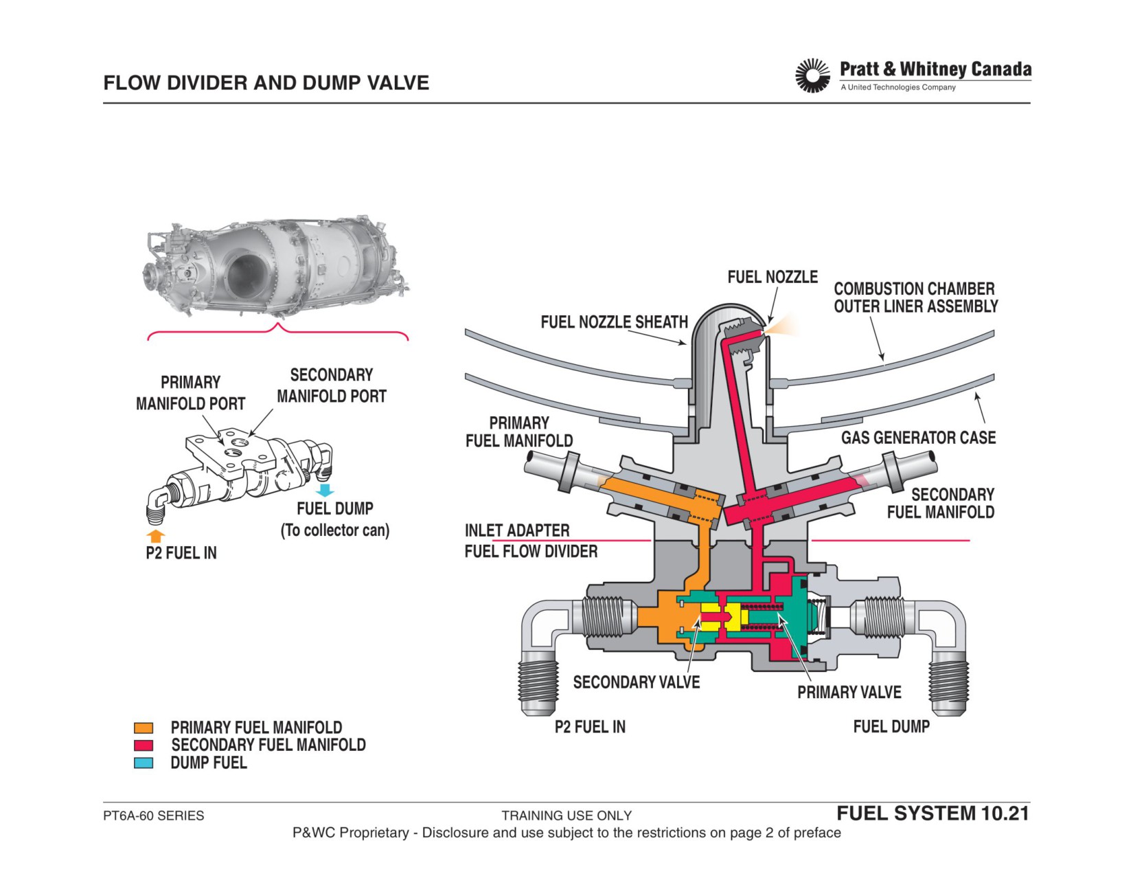
FLOW DIVIDER WITH DUMP VALVE
Function:
Operation:
Provides a means to separate the starting flow (primary)
When the condition lever is moved to the "fuel on" position,
from the normal engine running flow (Pri & Sec). Allows the
fuel enters the flow divider and pushes against the primary
fuel flow to be ported to a collector can during the shutdown
and secondary valve and spring. At a fuel pressure of 9 -
(dump) sequence.
13 psi, the primary valve moves to the right and allows fuel
to flow to the primary manifold only.
Description:
As Ng speed increases, fuel pressure increases (17-22
- Two concentric valves spring loaded to the closed
psid) in the flow divider and the secondary valve moves to
position
the right. At this point, Ng is at approximately 35% and fuel
- Fuel pressure operated
flows through all the nozzles.
When the fuel lever is moved to the "cut-off" position, the
Primary Flow:
fuel pressure drops rapidly and the two springs push the
primary and the secondary valves toward the closed posi-
Allows fuel to flow through primary manifold for starting. Pri-
tion. This allows the fuel to drain by gravity into a collector
mary valve opens at fuel pressure of 9 - 13 psi
can, preventing contamination (carbon deposits) of fuel
nozzles due to fuel residue.
Secondary Flow:
Maintenance:
Combined with the Primary flow, allows enough fuel flow to
- No maintenance at field level
operate the engine. Secondary valve opens at fuel pressure
- Visually inspect for cracks and leaks
of 17 - 22 psid.
Dump Position:
Allows fuel to dump into a collector can. Springs move the
Primary and Secondary valves to the cut-off position, port-
ing both manifolds to dump.
PT6A-60 SERIES
TRAINING USE ONLY
FUEL SYSTEM 10.20
P&WC Proprietary - Disclosure and use subject to the restrictions on page 2 of preface
FLOW DIVIDER WITH PURGE VALVE
(SB 13074, 14065)
Operation:
Function:
When the fuel lever is moved to the "fuel on" position, fuel
enters the flow divider and pushes against the primary and
Provides a means to separate the starting flow (primary)
secondary valves.
from the normal engine running flow (Pri & Sec). Allows the
fuel flow to be purged (blown) back to the Combustion
At a pressure of 9 - 13 psi, the primary valve moves to the
Chamber to be burnt during the shutdown sequence.
right and allows fuel to flow in the primary manifold at a
pressure providing optimum fuel atomization.
Description:
- Two concentric valves spring loaded to the closed
As Ng speed increases, fuel pressure goes up and at 17 -
position
22 psid, the secondary valve moves to the right. At this
- A P3 purge check valve separates the fuel side from
point, Ng is spooling through 35% and fuel flows through all
the air side
the nozzles.
- Fuel/Air pressure operated
When the fuel lever is moved to the cut-off position, fuel
Primary Flow:
pressure drops and the two springs push the primary and
Allows fuel to flow through primary manifold for starting. Pri-
secondary valves into the purge position. P3 air, accumu-
mary valve opens at fuel pressure of 9 - 13 psi, and forces
lated in a purge can, pushes the check valve open and
shut the P3 purge check valve.
blows the remaining fuel in the manifold and fuel nozzles in
the combustion chamber where it is burned. This may
Secondary Flow:
cause a small Ng and T5 spike during shutdown.
Combined with the Primary flow, allows enough fuel flow to
operate the engine. Secondary valve opens at fuel pressure
Maintenance:
of 17 - 22 psid.
- No maintenance at field level
- Visually inspect for cracks and leaks
Purge:
- Verify airframe check valves and purge canister.
- P3 air accumulator (airframe).
- Opens the check valve.
- Purges the fuel from transfer tubes and nozzles into
the Combustion Chamber.
PT6A-60 SERIES
TRAINING USE ONLY
FUEL SYSTEM 10.22
P&WC Proprietary - Disclosure and use subject to the restrictions on page 2 of preface
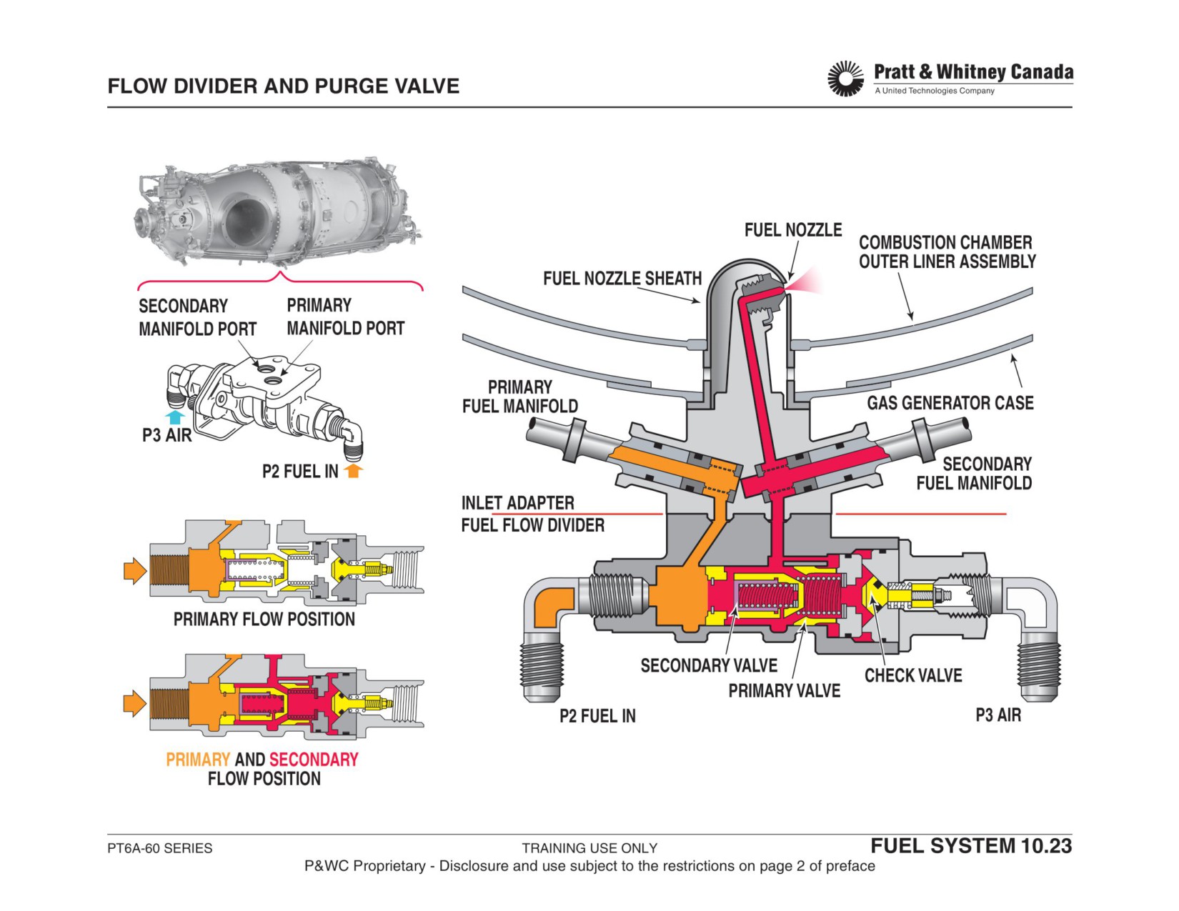
SIMPLEX FUEL NOZZLES (A52/60/61, A64, A65)
Function:
Maintenance:
- Clean or replace nozzles every 400 hours
Deliver and atomize metered fuel into the combustion
- New operator clean every 200 hours
chamber.
- Alternate cleaning method, in situ cleaning every 200
hours to extend intervals between removals
- Leak test if nozzles tips are removed
Construction:
- Check for erosion and fretting wear on nozzle sheaths
- 14 fuel nozzle adapters, 7 primary, 7 secondary
- Upgrades from Simplex to Duplex type nozzles:
- 14 sheaths
-
SB 13182…….A65’s
- 14 fuel nozzle tips
-
SB 14053…….A64
- 28 transfer tubes (manifolds)
-
SB 14067…….A66/67,A,R,AF
Warning:
Operation:
Badly Spraying Nozzles Will Reduce Hot Section Compo-
On start, fuel flows through the primary manifolds and the
nent Life
seven primary fuel nozzles. The position of the primary fuel
nozzles is such that fuel is sprayed circumferentially
towards the spark igniters in order to facilitate ignition.
An increase in Ng causes fuel pressure to increase and the
secondary fuel nozzles to spray fuel into the combustion
chamber.
During operation, all 14 fuel nozzles receive fuel from the
flow divider and deliver it to the combustion chamber.
PT6A-60 SERIES
TRAINING USE ONLY
FUEL SYSTEM 10.24
P&WC Proprietary - Disclosure and use subject to the restrictions on page 2 of preface
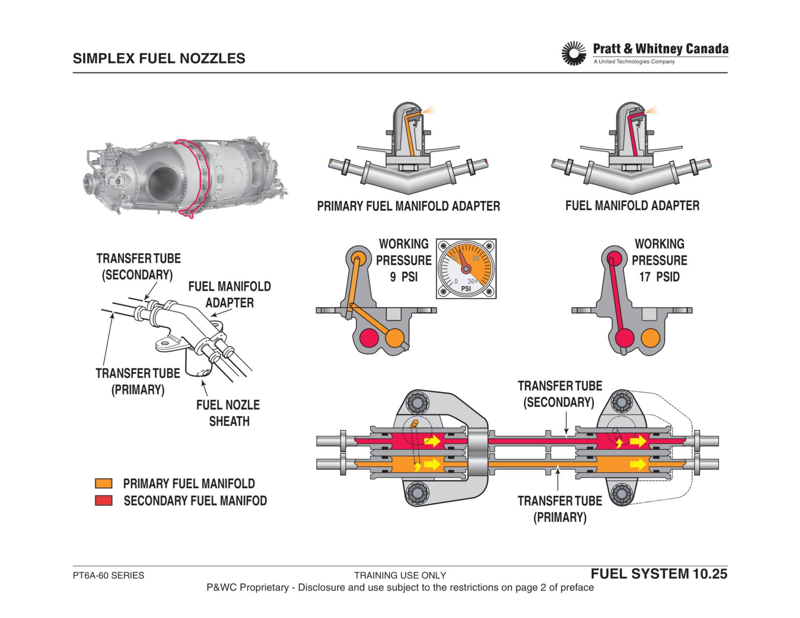
DUPLEX FUEL NOZZLES (A67B/D/F/P AND POST SB FOR OTHERS)
Function:
Maintenance:
- Clean or replace nozzles every 400 hours.
Deliver and atomize metered fuel into the combustion
- New operator should clean every 200 hours.
chamber.
- Alternate cleaning method, in situ cleaning every 200
hours to extend intervals between removals.
- Leak test if nozzles tips are removed.
Construction:
- Check for erosion and fretting wear on nozzle sheaths.
- 14 fuel nozzle adapters
- 14 fuel nozzle sheaths
Warning:
- 14 fuel nozzle tips
- 28 transfer tubes
Badly spraying nozzles will reduce Hot Section compo-
nent life
Operation:
On start, the flow divider sends fuel to the primary mani-
folds. The 14 fuel nozzles will deliver fuel to the combustion
chamber through the Primary passage.
As Ng increases, the fuel pressure increases. The second-
ary fuel nozzle passages will spray fuel into the combustion
chamber.
During operation, both Primary and Secondary passages of
the 14 fuel nozzles receive fuel from the flow divider and
deliver it to the combustion chamber.
PT6A-60 SERIES
TRAINING USE ONLY
FUEL SYSTEM 10.26
P&WC Proprietary - Disclosure and use subject to the restrictions on page 2 of preface
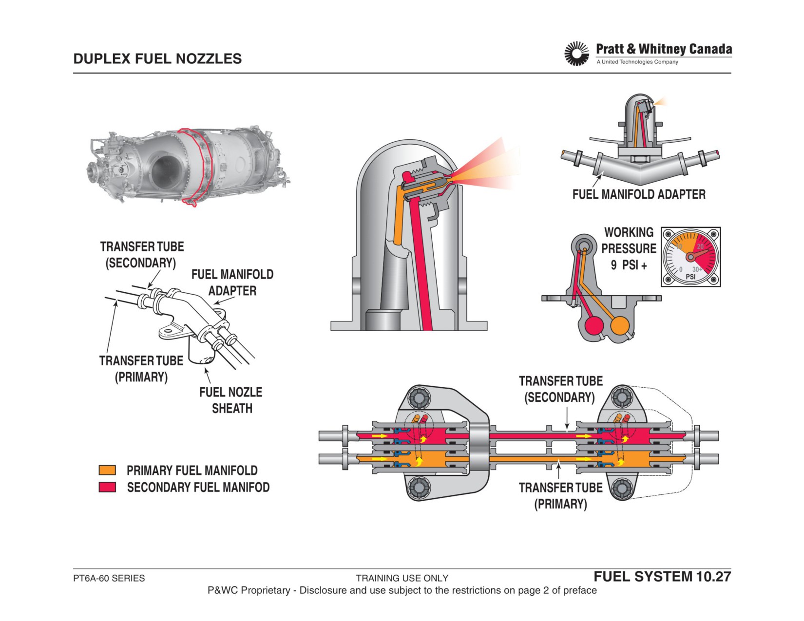
FUEL CONTROL UNIT MANUAL OVERRIDE
Function:
The P1 to Pz pressure differential will move the fuel valve
down to increase fuel flow.
Allows the pilot to manually control the FCU fuel valve in the
event of a pneumatic (P3, Py) system malfunction.
A return spring below the P2 valve ensures the valve fol-
lows the bellows movement during normal operation. In the
event of a pneumatic failure (P3 or Py), it is easier to com-
Installed on the following:
press the return spring than the bellows; so less force is
- A-60AG
required to move the MOR and the Pz valve.
- A-64
- A-65AG
SB 13196
- A66A, A66D
Caution:
- A-67B/P
- A-67AG
Move manual override lever slowly
Operation:
In the event of a P3/Py air loss or metering unit malfunction,
Maintenance:
the pilot can manually control the position of the fuel valve
- Operate manual override system regularly to confirm
by simulating the action of P3 air pressure. A special lever
proper operation and familiarize with engine response
is provided in the cockpit to that effect.
in this mode
Movement of the Manual Override Lever (MOL) will
increase spring pressure on the rate piston, forcing it to
move. The rate of movement is established by the orifice
which dampens any abrupt MOL movement. The rate pis-
ton movement is transmitted to the Manual Override Rod
(MOR) that runs through the center of the fuel valve. The
MOR forces the P2 valve down allowing Pz pressure to
bleed to Po.
PT6A-60 SERIES
TRAINING USE ONLY
FUEL SYSTEM 10.28
P&WC Proprietary - Disclosure and use subject to the restrictions on page 2 of preface
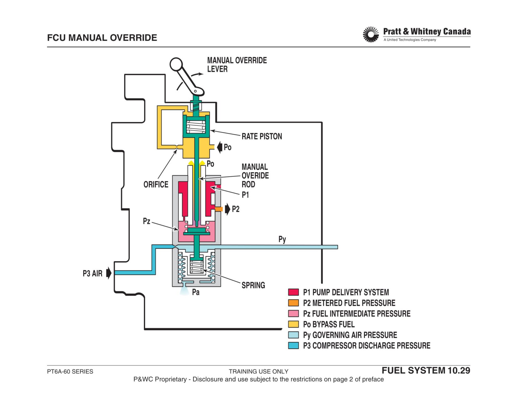
POWER RECOVERY SYSTEM (PT6-A65R/AR AND 67R ONLY)
Function:
On twin engine aircraft’s, provides manual or automatic
power increase on one engine in the event of a severe
power loss from the opposite engine.
Description:
A solenoid valve activated by a low torque reading on the
failed engine allows P3 air to push on a piston located at the
back of the FCU. The piston then rotates an eccentric shaft
changing the position of the cam follower on the 3D cam.
The movement of the follower on the cam is designed to
cause a rotation of the fuel valve and increases Ng by
approximately 4%. The system is used during take-off only.
A P3 bleed to atmosphere allows the servo piston to return
when power recovery is selected off (solenoid valve
closed).
Maintenance:
Check and adjust Ng increase as per Airframe Maintenance
Manual.
PT6A-60 SERIES
TRAINING USE ONLY
FUEL SYSTEM 10.30
P&WC Proprietary - Disclosure and use subject to the restrictions on page 2 of preface
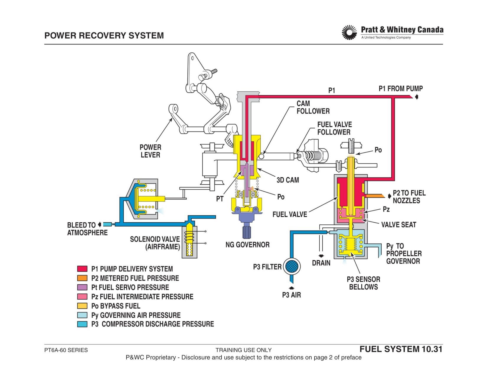
OVERTORQUE LIMITER
Function:
A solenoid (deleted by SB 14185) valve is used on the A-
67B and A-67AF to disable the torque limiter when not
A back-up unit which prevents engine overtorques. The pilot
required. The solenoid valve closes when de-powered. It
is always responsible for operating the engine within limits.
controls the supply of Py to the torque limiter.
Description:
Maintenance:
- Adjust unit as per Airframe Maintenance Manual so
A oil bellows which senses torquemeter oil pressure and is
that the required torque value is not exceeded.
linked to a Py bleed orifice. Found on the following engines:
- Pressure check unit to ensure Py does not leak.
- A-64
- Replace unit if defective.
- A-66B/D
- A-67AF post SB 14056
- A-67B post SB 14154
- A-67T
Operation:
Oil from the torquemeter chamber passes through a restric-
tor before entering the bellows. The restrictor dampens
torque pressure fluctuation and prevents damage to the bel-
lows assembly. When torque pressure reaches a specified
limit above maximum permitted torque, the bellows
expands and compresses the spring.
The flapper valve then moves to allow Py air pressure from
the fuel control unit to bleed to the atmosphere and there-
fore limit the fuel supply to the engine.
Bimetallic disks are mounted on the spring to compensate
for variation of spring tension caused by change in ambient
temperature.
PT6A-60 SERIES
TRAINING USE ONLY
FUEL SYSTEM 10.32
P&WC Proprietary - Disclosure and use subject to the restrictions on page 2 of preface
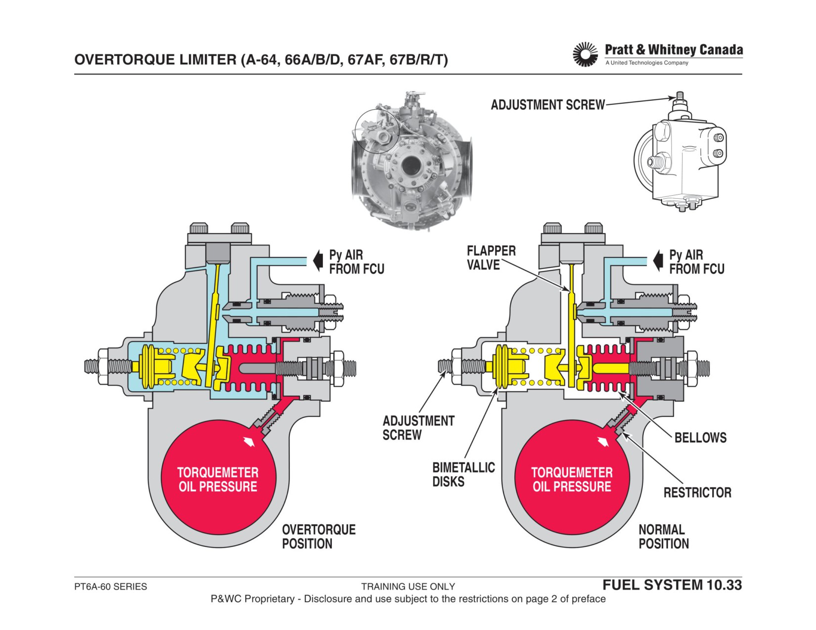
FUEL CONTROL UNIT ADJUSTMENT
Deadband
- Adjust deadband first, by deadband adjustment screw.
- Clockwise increases the deadband angle.
- Always verify low idle after a deadband adjustment.
Low Idle
- Always adjust before high idle setting
- Loosen FCU lever clamping screw
- To increase Ng, loosen top screw, tighten lower one
- To decrease Ng, loosen lower screw, tighten top screw
- When adjusting Ng, turn screw in increments of 1/6 of a turn at a time
High Idle
- High idle can be adjusted at two location on the FCU
- Adjust at cam follower adjustment screw if there is no stagger in the condition lever.
- Adjust High idle stop screw if the condition levers are staggered.
- Clockwise rotation increases Ng 1.5% per turn
Maximum Ng,
- Adjust as per Airframe Maintenance Manual
Reverse Ng,
Reserve Power
PT6A-60 SERIES
TRAINING USE ONLY
FUEL SYSTEM 10.34
P&WC Proprietary - Disclosure and use subject to the restrictions on page 2 of preface
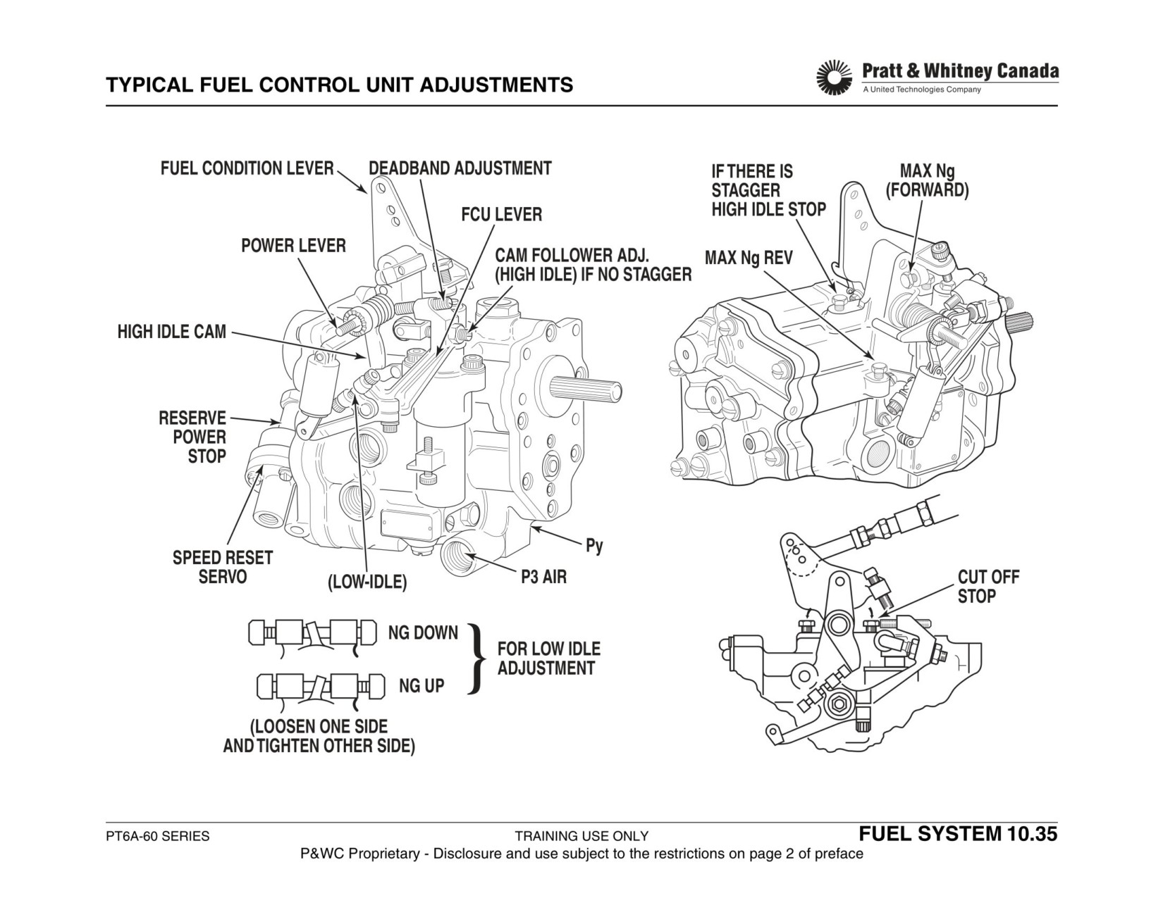
FUEL SYSTEM TROUBLESHOOTING SUMMARY
Observed Problem
Verification
Engine Does Not Start / Hot
- Ensure that minimum cranking speed is achievable
Starts
- Verify igniters for proper operation
- Check for evidence of fuel flow to the flow divider while motoring the engine
- Ensure primary and secondary fuel nozzles are in their respective position (N/A
for engines equipped with duplex nozzles)
- Replace flow divider
- Replace fuel nozzles
- Weak batteries
Engine Hangs Below Idle
- Ensure starting procedure is carried out properly
(Hung Start 30-35% Ng)
- Flow divider secondary valve not opening
Engine Is Slow To Accelerate To
- Ensure starting procedure is carried out properly
Idle
- Check for possible restriction in the P3 air line to the FCU
- Possible Py leaks
- Replace flow divider
- Replace FCU
Sub-Idle Condition (40-45% Ng)
- P3/Py line leaking or broken. P3 filter blocked
- Prop. Governor or Torque Limiter leaking Py.
- FCU bellows broken or leaking
White Smoke On Shut Down
- Verify for proper operation of flow divider and dump/ purge valve
From Exhaust Duct
- Replace FCU
Ng Coupling Failure
- Engine will go to 85% power
Fuel Leakage Between FCU And
- Remove FCU from pump and replace o-ring at fuel bypass port
Fuel Pump
- Replace FCU and pump if fuel leakage persists
PT6A-60 SERIES
TRAINING USE ONLY
FUEL SYSTEM 10.36
P&WC Proprietary - Disclosure and use subject to the restrictions on page 2 of preface
PROPELLER SYSTEM
PROPELLER SYSTEM
PT6A-60 SERIES
TRAINING USE ONLY
PROPELLER SYSTEM 11.1
P&WC Proprietary - Disclosure and use subject to the restrictions on page 2 of preface
PROPELLER SYSTEM
Function:
Change the power produced by the engine into thrust in
order to propel the aircraft through the air.
Description:
- Three to six bladed propellers
- Made of Aluminium or Composite materials
- Variable pitch, single acting type
- Propeller governor (CSU) controls:
-
Propeller Speed in governing mode.
-
Blade Angle in Beta mode.
List Of Topics:
- Propeller system
- Pitch change mechanism
- Governing mode
- Beta mode
- Primary blade angle
- Reverse thrust
- Feathering
- Propeller overspeed governor
- Np governor
- Propeller governor adjustments
PT6A-60 SERIES
TRAINING USE ONLY
PROPELLER SYSTEM 11.2
P&WC Proprietary - Disclosure and use subject to the restrictions on page 2 of preface
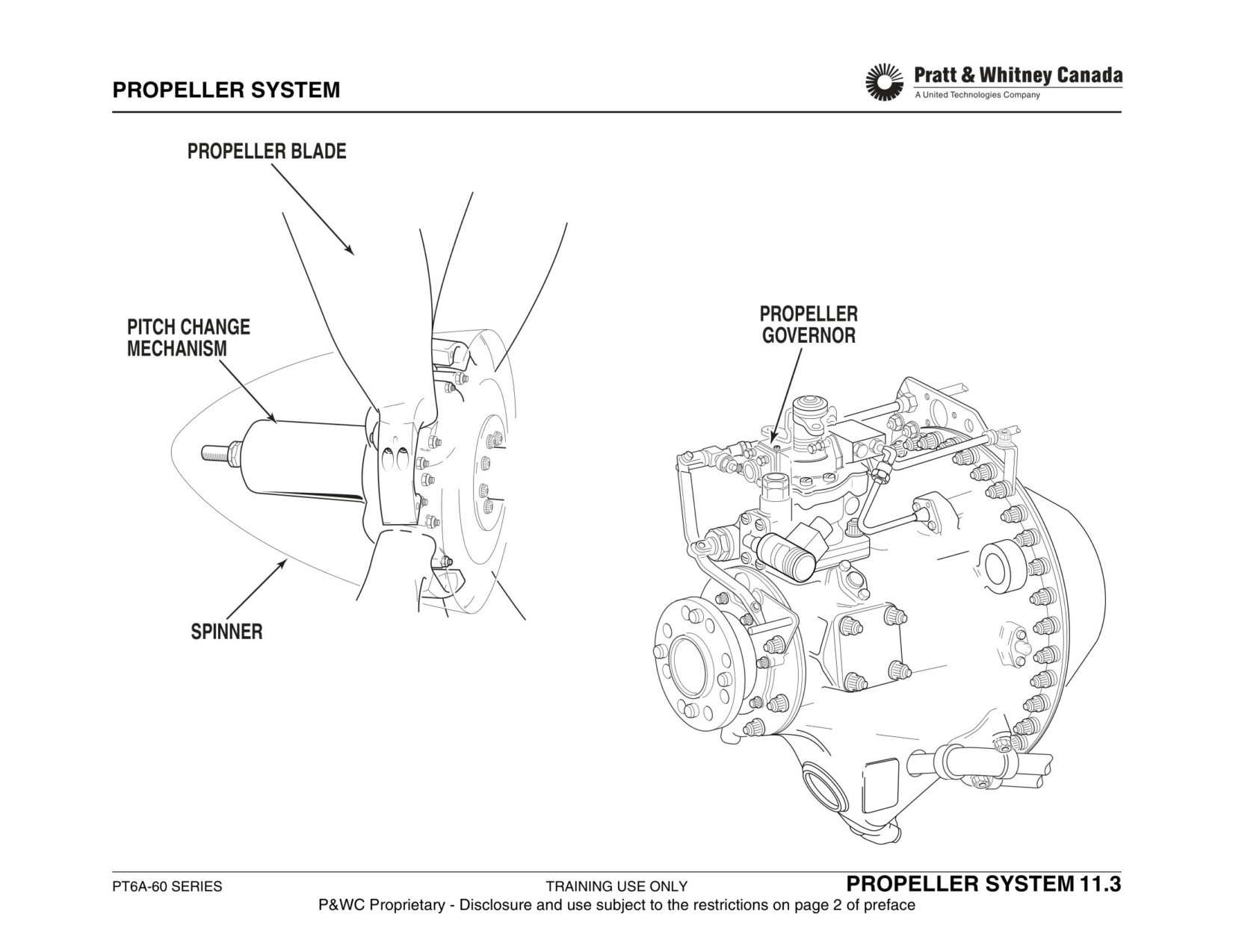
PITCH CHANGE MECHANISM
Function:
When oil pressure is decreased, the return spring and
counter weights force the oil out of the servo piston and
Allow varying the propeller blade angle in order to maintain
change the blade pitch to a coarser position.
a constant Np through various ambient conditions and
power settings.
An increase in oil pressure drives the blades towards a finer
pitch.
Description:
- Hollow spider hub supports the blades
CSU Action
Propeller Reaction
Max Position
- Feathering spring attached to the servo piston (dome)
- Centrifugal counterweights on each blade working with
Oil In
Finer Pitch
Reverse
the feathering spring drive the propeller blade toward
(lower pitch)
feather
(faster prop RPM)
- Oil pressure from the propeller governor drives the
Oil Out
Coarser Pitch
Feather
propeller towards reverse position
(higher pitch)
(slower prop RPM)
Operation:
Oil from the propeller governor feeds into the propeller shaft
Maintenance:
and to the servo piston via the oil transfer sleeve mounted
- Refer to the Airframe Maintenance Manual.
on the propeller shaft.
As oil pressure increases, the servo piston is pushed for-
ward and the feather spring is compressed. Servo piston
movement is transmitted to the propeller blade collars via a
system of levers.
PT6A-60 SERIES
TRAINING USE ONLY
PROPELLER SYSTEM 11.4
P&WC Proprietary - Disclosure and use subject to the restrictions on page 2 of preface
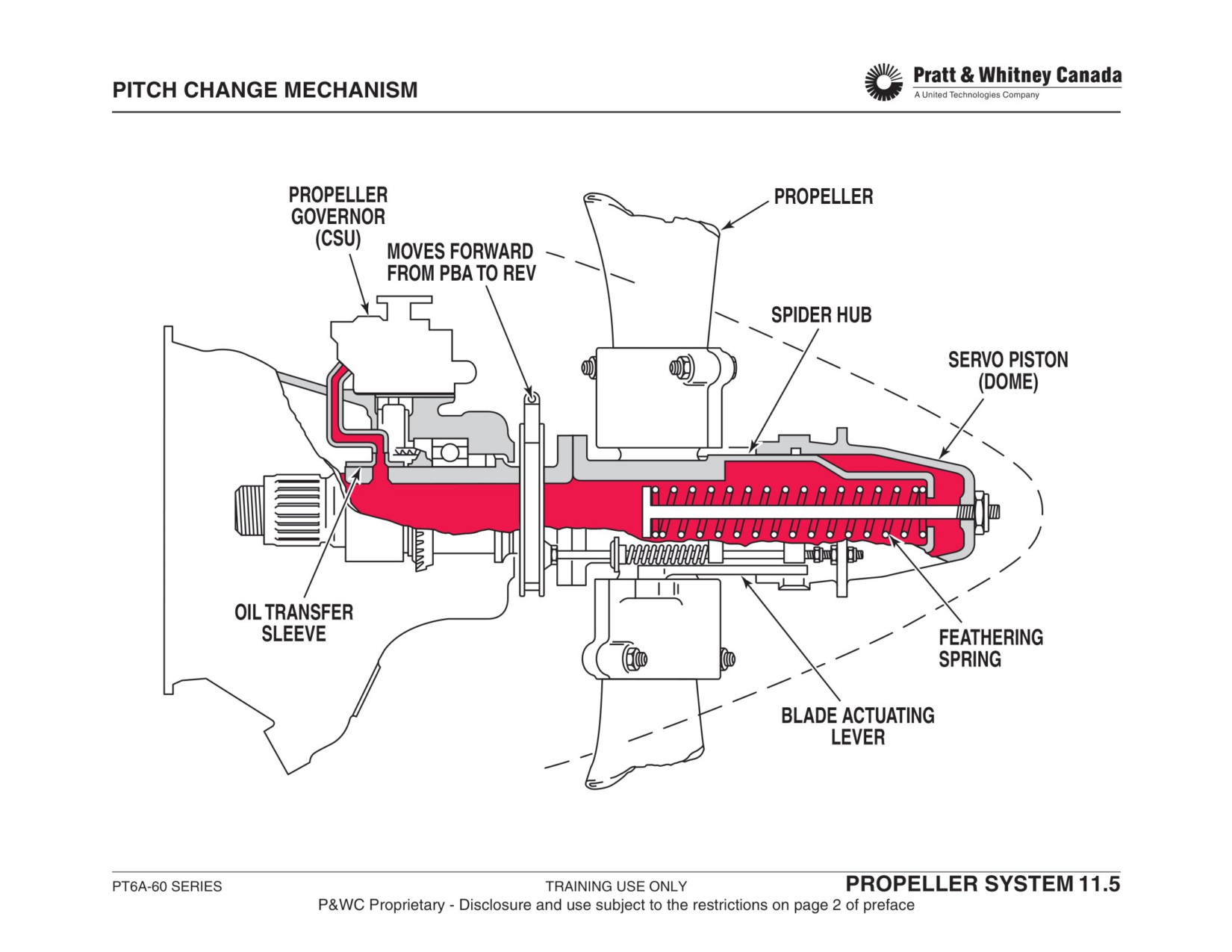
PROPELLER GOVERNOR GOVERNING MODE
Description:
Speeder Spring:
- Opposes a mechanical force to the centrifugal force of
Is the range of operation where engine power is sufficient to
the flyweights
maintain the selected propeller speed by varying the blade
- Determines the propeller speed at which the flyweights
angle (pitch).
will be "on speed."
- The pilot controls spring tension through the propeller
The System Is In The Governing Mode When:
lever (not on A-67B/P).
- Indicated propeller speed matches selected NP.
- increase in Ng speed do not affect Np.
Operation:
- Moving the propeller lever results in a change in Np
Oil is supplied to the governor. A gear pump, mounted at
the base of the governor, increases the flow of oil going to
Components:
the CSU relief valve. When the oil pressure reaches the
desired level, the relief valve opens to maintain the pres-
Pressure Relief Valve:
sure.
- Opens to bypass oil when maximum pressure is
When the speed selected by the pilot is reached, the fly-
reached (450 to 720 depending on the model)
weights force equals the spring tension of the speeder
spring. The governor flyweights are then on speed.
Pump Gears:
When the engine output power is increased, the power tur-
- Supply oil pressure to control the propeller pitch
bines tend to speed up. The flyweights in the CSU sense
this acceleration. The flyweights go into an overspeed con-
Governor Flyweights:
dition because of the increase centrifugal force and force
- Rotation of the flyweights generate a centrifugal force
the control valve to move up and restrict oil flow to the pro-
proportional to the propeller speed
peller dome. The feathering spring increases the propeller
- Flyweight force pushes against a spring to move the
pitch to maintain the selected speed. Reducing power
control valve up or down
causes an under-speed of the flyweights, downward move-
ment of the control valve, more oil in propeller dome, result-
Pilot Valve:
ing in a finer pitch to control propeller speed.
- Moves up and down under the influence of the fly-
The propeller governor houses an electro-magnetic coil,
weights
which is used to match the rpm of both propellers during
- Controls the oil pressure going to the propeller
cruise. An aircraft supplied synchro-phaser unit controls
this function.
PT6A-60 SERIES
TRAINING USE ONLY
PROPELLER SYSTEM 11.6
P&WC Proprietary - Disclosure and use subject to the restrictions on page 2 of preface
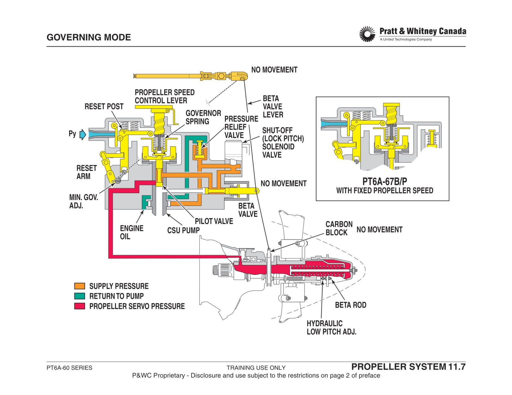
PROPELLER GOVERNOR
BETA MODE (FORWARD OPERATION)
Power Lever:
Description:
On the ground, movement of the power lever below the idle
gate causes the reversing cam to actuate the beta valve,
The beta mode corresponds to a range of operation where
thus causing the blade angle to reduce
the blade angle is between PBA (Primary Blade Angle) and
reverse. The propeller pitch is a direct function of the beta
valve position (power lever)
Operation:
At low power, the propeller and governor flyweights do not
turn fast enough to compress the speeder spring. In this
Function:
condition, the control valve moves down and high pressure
- Prevents the blade angle from going below minimum in
oil pushes the dome forward, moving the blades towards a
flight
(Primary Blade Angle, PBA)
finer pitch.
- Allows the pilot to manually control the blade angle on
The propeller dome in it's forward movement contacts the
the ground for taxiing and reverse operation
beta nuts. Any further movement pulls the beta rod and the
slip ring forward. The forward motion of the slip ring is
transmitted to the beta valve via the beta lever and the car-
You Are In The Beta Mode When:
bon block. Forward movement of the beta valve stops the
- Indicated Np is below selected Np
oil supply to the propeller. This prevents the blade angles
- A change in Ng speed causes a Np change
from going any finer. This is called "Primary Blade Angle"
- Propeller lever movement does not change Np
(PBA) and it is the minimum blade angle allowed for flight
operation.
Beta Feedback System:
From this point the propeller is in the beta mode. If the
engine power is reduced when the propeller is at the pri-
In low pitch operation, the beta nuts, beta rods, slip ring,
mary blade angle, the propeller speed will decrease since
carbon block and the beta lever, which compose the beta
the blade angle does not change.
feedback system, actuate the beta valve
PT6A-60 SERIES
TRAINING USE ONLY
PROPELLER SYSTEM 11.8
P&WC Proprietary - Disclosure and use subject to the restrictions on page 2 of preface
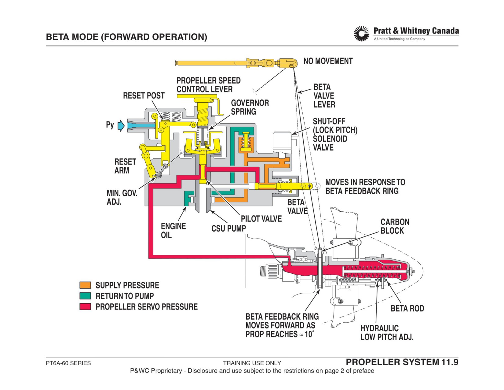
PROPELLER GOVERNOR (CONT’D)
Lockpitch Solenoid Valve:
Prevents the propeller from going into reverse or below the
primary blade angle in the event of a Beta system malfunc-
tion in flight. The solenoid is energized by a switch (air-
frame supplied) mechanically connected to the propeller
slip-ring linkage via a second carbon block.
Any movement of the slip ring towards reverse blade angle,
prior to the pilot selecting reverse, energizes the solenoid
and stops the oil flow from the governor pump to the propel-
ler servo. This controls the blade angle from going any
finer.
As oil pressure leaks off around the propeller shaft oil trans-
fer sleeve, the blade angle slowly drifts back toward coarse
pitch. This will de-activate the low pitch solenoid valve and
restore the oil supply to the propeller servo. The low pitch
solenoid valve will cycle (close/open) as back-up to the beta
valve function.
PT6A-60 SERIES
TRAINING USE ONLY
PROPELLER SYSTEM 11.10
P&WC Proprietary - Disclosure and use subject to the restrictions on page 2 of preface
PROPELLER GOVERNOR
BETA MODE (REVERSE OPERATION)
As Np increases due to the increase in engine power, the
governor flyweights begin to move outwards. Since the
Function:
reset lever is closer to the speeder spring cup, the cup con-
tacts the reset lever before the flyweights would normally
Allows the pilot to control the propeller with a negative blade
reach the on-speed position (95% Np instead of 100%).
angle. (Reverse thrust).
When the reset lever is pushed up by the flyweights/
speeder spring cup, Py bleeds from the Fuel Control Unit
(FCU) which lowers the Wf, engine power and thus propel-
Operation:
ler speed.
Moving the power lever backwards causes the reversing
In reverse Np remains 5% below the selected propeller
cam and cable to move the beta valve backward, allowing
speed so that the control valve remains fully open and only
more oil to flow into the propeller dome, causing the blades
the beta valve controls the oil flow to the propeller dome.
to go towards reverse pitch.
In this mode, the propeller speed is no longer controlled by
As the blades move to reverse, the slip ring is pulled forward
changing the blade angle ( i.e.: servo pressure). It is now
by the dome (beta nuts) and moves the beta valve outward
controlled by limiting engine power (i.e.: Ng speed).
restricting the oil flow. This stops the blade movement
toward reverse. To obtain more reverse thrust, the power
lever must be moved back more to reset the beta valve
inward and repeat the process.
The reset arm on the CSU is moved rearward by the inter-
connecting rod at the same time as the blade angle is mov-
ing toward reverse. This causes the reset lever and reset
post to move down in the CSU. This brings the reset lever
closer to the speeder spring cup.
PT6A-60 SERIES
TRAINING USE ONLY
PROPELLER SYSTEM 11.12
P&WC Proprietary - Disclosure and use subject to the restrictions on page 2 of preface
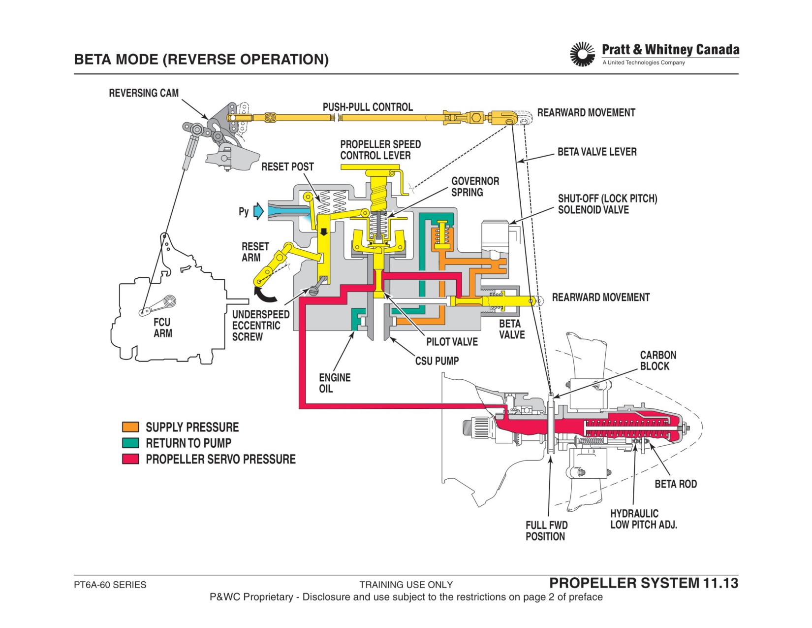
PROPELLER FEATHERING
Function:
Maintenance:
Minimise propeller drag by streamlining the blades in the
Check feathering operation as per Airframe Maintenance
event of an in-flight engine shutdown.
Manual instruction.
Adjustment:
Description:
Adj. Feather screw CW -> Increases the time to feather
Bringing the propeller lever to the feather position causes
Adj. Feather screw CCW->Decreases the time to feather
the speed selection lever on the CSU to push the feathering
valve plunger and allows propeller servo oil to dump into the
reduction gearbox sump.
The pressure loss in the propeller hub causes the feather-
ing spring and the propeller counterweights to feather the
propeller quickly.
Note:
The A-67B/P propeller governor has no provision for speed
control. Feathering is done through a feather solenoid
located on the propeller overspeed governor.
The A-64 propeller governor has no feathering valve.
Feathering is done through physically lifting the control
valve by rotating propeller speed actuating lever completely
CCW.
PT6A-60 SERIES
TRAINING USE ONLY
PROPELLER SYSTEM 11.14
P&WC Proprietary - Disclosure and use subject to the restrictions on page 2 of preface
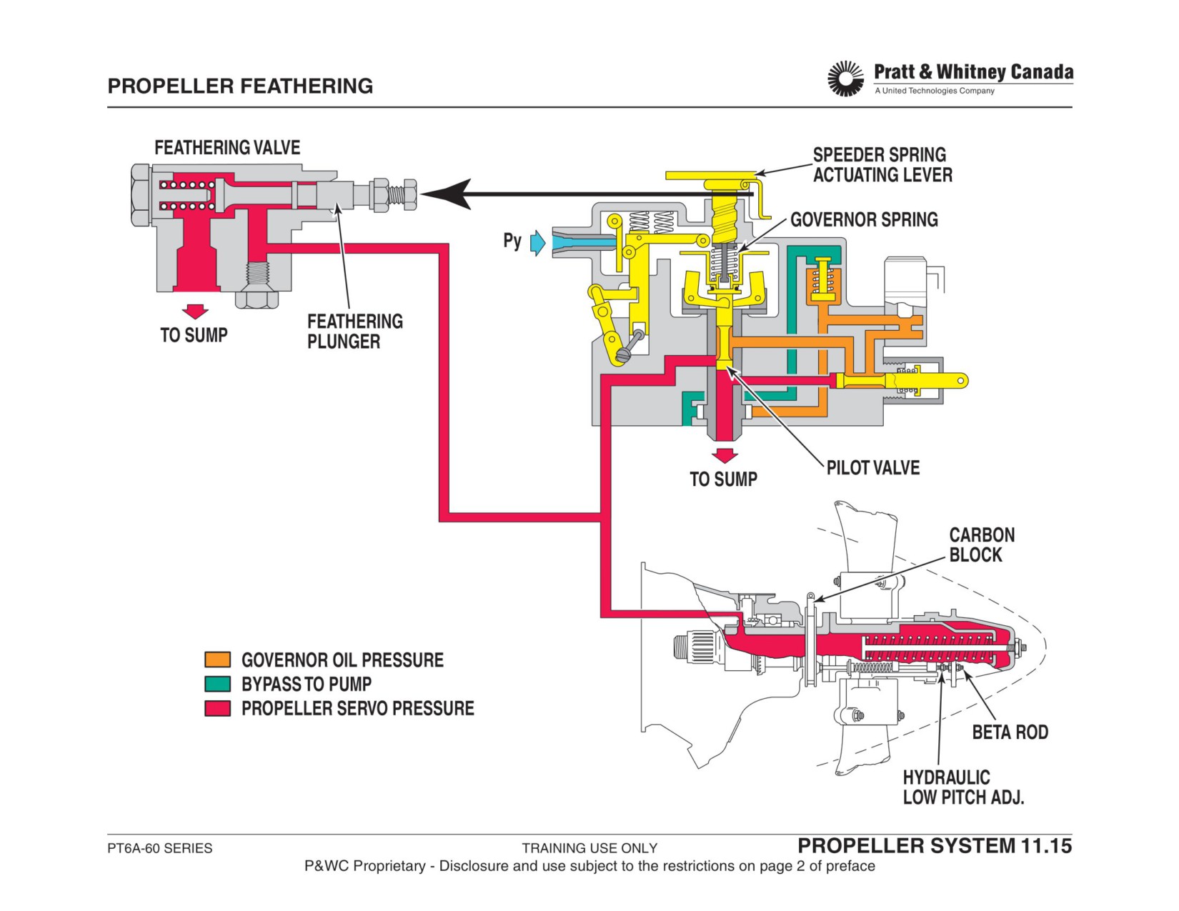
NF GOVERNOR (OVERSPEED PROTECTION)
Description:
The movement of the reset lever around its pivot point
opens the Py air passage. Py bleeds into the reduction
The CSU contains a Py bleed orifice closed by a ‘flapper’
gearbox limiting the fuel supply to the engine. This will pre-
valve and reset lever. The ‘flapper’ valve/reset lever can be
vent the propeller/power turbines from accelerating beyond
opened by the speeder spring cup when the flyweights
106%.
react to an increase in centrifugal force caused by an over-
speed of the propeller/power turbines.
Maintenance:
- Adjust speed limit in reverse using the underspeed
In Forward Propeller Operation:
eccentric screw (max rev screw).
- Over-speed limit adjustment in forward propeller oper-
Provides Np overspeed protection (6% above selected
ation is not permitted.
prop speed) by bleeding-off Py air pressure from the FCU
- Check for Py leakage which will cause a loss of perfor-
thus reducing the power of the engine.
mance.
In Reverse Propeller Operation:
Limits propeller speed to a value approximately 5% below
the selected Np by bleeding-off Py air pressure from the
FCU thus reducing the power of the engine.
Operation:
In the event of a propeller overspeed not controlled by the
propeller overspeed governor (oil governor), the flyweights
in the propeller governor will move outwards until the
speeder spring cup contacts the reset lever.
PT6A-60 SERIES
TRAINING USE ONLY
PROPELLER SYSTEM 11.16
P&WC Proprietary - Disclosure and use subject to the restrictions on page 2 of preface
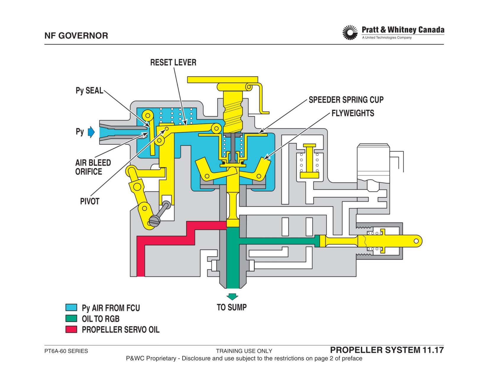
PROPELLER OVERSPEED GOVERNOR
(AIRFRAME OPTION)
increase in blade pitch puts more load on the engine and
slows down the propeller.
Function:
To test the unit, the speed reset solenoid is activated and
Provides back up protection against propeller and power
servo oil pressure pushes against the reset piston to cancel
turbine over speeds (4% over max prop speed).
the effect of the reset spring. With less spring tension act-
ing on the flyweights, the overspeed governor can be tested
at speeds lower than maximum.
Description:
- Airframe supplied except on A-67B/P
On twin installation, a second solenoid valve is mounted on
- Flyweight governor actuating a control valve
the overspeed governor and is used in conjunction with the
- One solenoid valve to reset the unit during ground
aircraft auto-feather system. The system is switched on for
tests
take off and in the event of an engine malfunction will ener-
- One solenoid to feather the propeller
gize the solenoid valve to dump propeller servo oil into the
reduction gearbox sump. The feathering spring and propel-
On the PT6A-67B, the overspeed governor feather solenoid
ler counter-weights move the blade quickly to feather.
is the only way to feather the propeller and the speed reset
solenoid is replaced with a mechanical reset lever mounted
on the governor.
Maintenance:
- Test the unit on a regular basis.
- With the reset solenoid energized, verify the speed at
Operation:
which the overspeed governor controls Np.
-
A67B/P: No solenoid, rotate mechanical reset
The governor houses a set of flyweight connected to a con-
lever to test
trol valve that is driven by a bevel gear mounted on the pro-
- Refer to the Airframe Maintenance Manual for adjust-
peller shaft. The flyweight's centrifugal force is acting
ment.
against two springs, a speeder spring and a reset spring.
When the propeller speed reaches a specified limit (4%
over maximum Np) the governor flyweights lift the control
valve and bleed off propeller servo oil into the reduction
gearbox sump, causing the blade angle to increase. An
PT6A-60 SERIES
TRAINING USE ONLY
PROPELLER SYSTEM 11.18
P&WC Proprietary - Disclosure and use subject to the restrictions on page 2 of preface
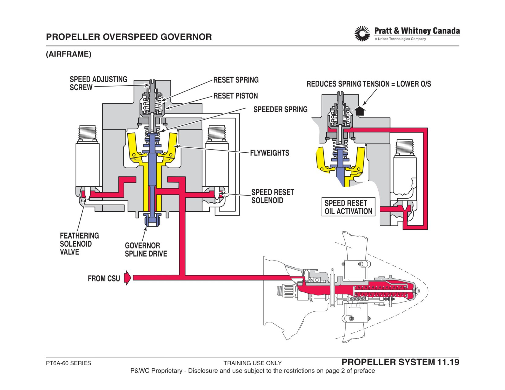
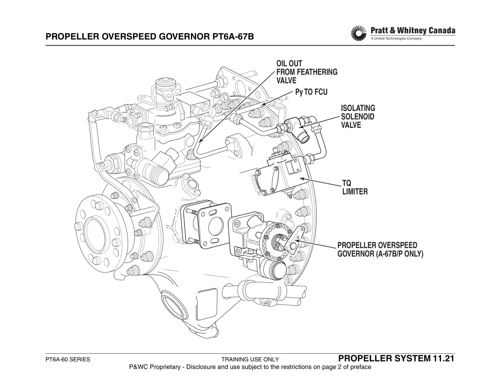
PROPELLER GOVERNOR ADJUSTMENTS
Maximum
- Set propeller lever at maximum position in the cockpit
Forward
- Ensure that max Np stop is contacted
Propeller
- Adjust screw CCW to increase maximum Np, CW to decrease.
Speed (Np)
- One flat alter Np 2% (A-67R/AF/AG), 4% (A-67/67A)
Maximum
- Set propeller lever at maximum Np position
Reverse
- Disconnect reset arm from interconnect rod
Propeller
- Secure reset arm against rear stop
Speed
- Move power lever forward until propeller speed stabilises
- Check that propeller speed stabilises within specified limits
- Adjust underspeed eccentric screw if required
- In some cases the FCU may not be adjusted to provide enough reverse power, this
requires an initial check/adjustment of the FCU before adjusting the CSU
Feathering Operation
- Set power lever at ground idle
Check
- Move propeller lever to the feather position note feathering time, adj. as req.
PT6A-60 SERIES
TRAINING USE ONLY
PROPELLER SYSTEM 11.22
P&WC Proprietary - Disclosure and use subject to the restrictions on page 2 of preface
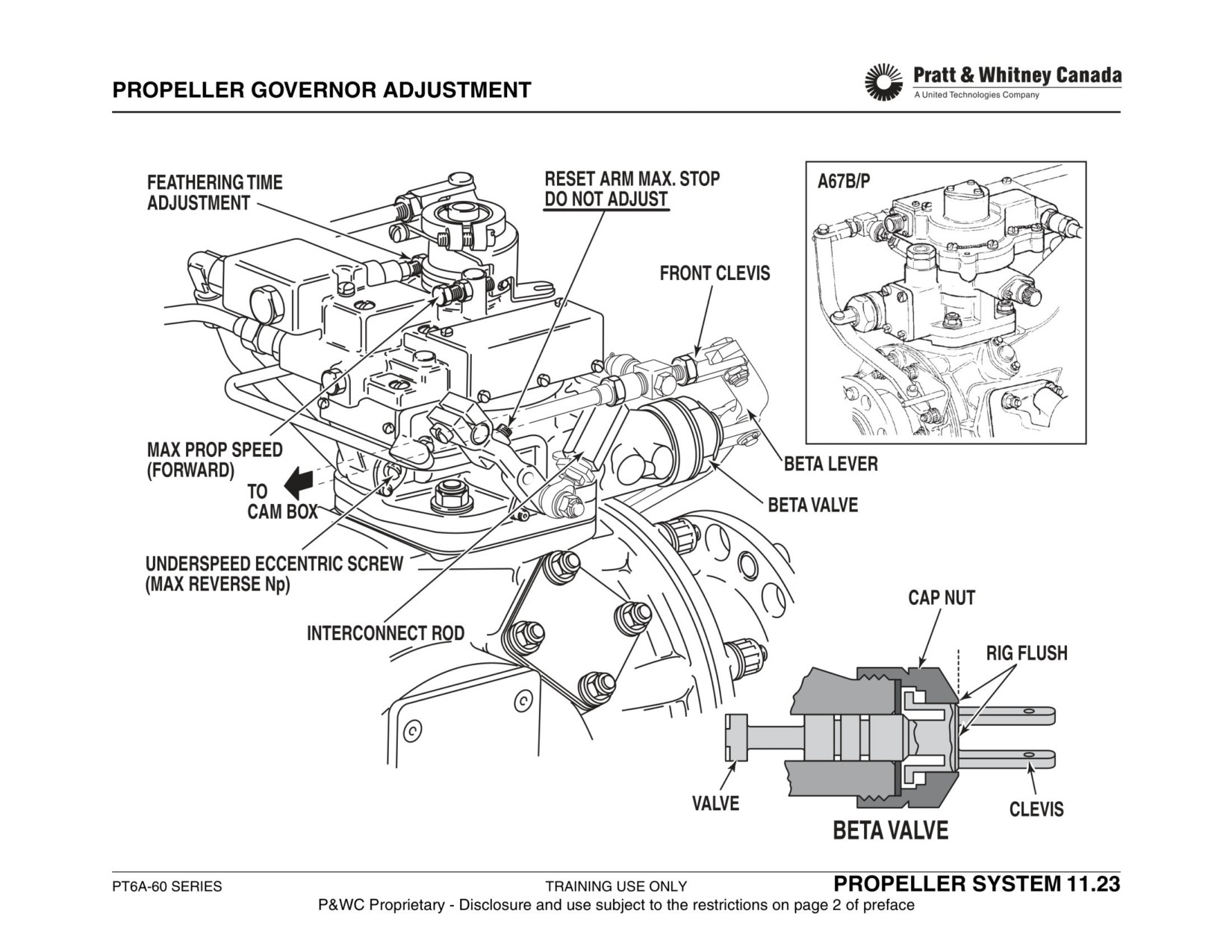
PRIMARY BLADE ANGLE (PBA) CHECK
Function:
Troubleshooting:
- Indicated torque lower than target = PBA too fine
Provide equal flight idle torques for appropriate aircraft han-
- Indicated torque higher than target = PBA too coarse
dling. On twin engine applications the aircraft may yaw if
PBA is not the same on both engines. On single engine air-
Adjust the beta valve position by adjusting the reversing
craft, approach handling characteristics are dependant on
cable clevis end
PBA.
- Move clevis end forward to increase torque
- Move clevis end rearward to decrease torque
Procedure:*
- Record OAT
Adjust beta nuts as per airframe manual to rectify
- Record field barometric pressure
- Move beta nuts rearward to increase torque
- Set propeller lever at maximum position
- Move beta nuts forward to decrease torque
- Increase power until target Np is reached
- Target Np speed is always less than maximum speed
Note:
to ensure the beta valve is actuated
Some airframe or propeller manufacturers do not
- Stabilise engine and record torque
allow adjusting the beta nuts . The only option left is to
- Compare indicated torque with torque given by chart in
adjust the beta valve inwards only . This will give a finer
Airframe Maintenance Manual
PBA on the higher indicating engine .
*(For reference only, refer to aircraft maintenance manual
for specific procedure)
PT6A-60 SERIES
TRAINING USE ONLY
PROPELLER SYSTEM 11.24
P&WC Proprietary - Disclosure and use subject to the restrictions on page 2 of preface
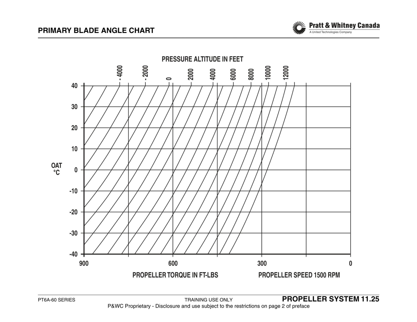
PROPELLER SYSTEM TROUBLESHOOTING
Observed Problem
Action Required
Np And Torque Fluctuations At High
Max Np setting may be too high (interference with OSG)
Power
Overspeed governor test solenoid leaking. (interferes with prop.Governor)
(No Ng Fluctuation)
Np And Torque Fluctuation At Low
Verify Beta ring is not distorted
Power
Inspect carbon block for excessive wear
(In Beta)
Check beta nut adjustment (not equal)
Propeller Slow To Unfeather
Carbon block worn out or beta valve rigged too far out
Low servo pressure from prop. governor
Np, Tq And Ng Fluctuation
Ensure reset arm is positively sitting against forward stop
(Power Fluctuation)
Verify Py line for leaks
Replace FCU if problem is still present
Propeller Rpm Too High (Governing)
Check propeller speed gauge for accuracy
Adjust maximum stop on governor
Replace prop. governor if adjustment is not effective
Propeller Rpm Too Low (Governing)
Insure max stop is contacted
Adjust maximum stop on governor
Ensure Ng is not limited by any P3 or Py leak.
Replace propeller governor
Check/Replace overspeed governor
Propeller Rpm Too Low
Check Nf governor minimum adjustment in reverse
(Reverse)
Adjust FCU maximum reverse Ng stop
Propeller Rpm Too High
Check that maximum forward propeller speed is OK
(Reverse)
Check proper rigging of the reset arm. May not be bleeding enough Py
Check Nf governor minimum adjustment in reverse
PT6A-60 SERIES
TRAINING USE ONLY
PROPELLER SYSTEM 11.26
P&WC Proprietary - Disclosure and use subject to the restrictions on page 2 of preface
MAINTENANCE PRACTICES
MAINTENANCE PRACTICES
PT6A-60 SERIES
TRAINING USE ONLY
MAINTENANCE PRACTICES 12.1
P&WC Proprietary - Disclosure and use subject to the restrictions on page 2 of preface
PERIODIC INSPECTION
The following table is for reference only, refer to your Engine
Maintenance Manual.
FREQUENCY
COMPONENTS
Routine : coincides with daily or pre-flight airframe inspec-
25 hours
2nd Power Turbine Blades
tion.
50 hours
2nd Stage PT Blades
Minor : coincides with a typical airframe inspection.
100 hours
Engine Oil
Notes:
Oil Filter Element
1)The intervals at which these inspections are per-
formed may be altered by the aircraft manufacturer’s
AGB Drive
maintenance program and approved by the opera-
P3 Air Filter
tor’s local airworthiness authority.
2)Engines operating in sandy or dusty environments or
P3 Air Filter Drain Valve
in smog or salt-laden atmospheres should be sub-
Chip Detector
jected to additional inspections for corrosion and
compressor erosion.
125 hours
2nd Power Turbine Blades
Minor
Control Linkage
FREQUENCY
COMPONENTS
Fuel Control Unit
Routine
Oil Level
Manual Override FCU
Oil Filler Cap
Fuel Pump
Fuel System
Fuel Pump Outlet Filter
Fuel & Oil Lines
Oil-to Fuel Heater
Scavenge Oil Pump Housing
P3 Air Filter
Propeller Oil Shaft Seal
P3 Air Filter Bowl
Accessories
Oil Filter Element
PT6A-60 SERIES
TRAINING USE ONLY
MAINTENANCE PRACTICES 12.2
P&WC Proprietary - Disclosure and use subject to the restrictions on page 2 of preface

PERIODIC INSPECTION (CON’T)
FREQUENCY
COMPONENTS
FREQUENCY
COMPONENTS
Minor
Tubing, Wiring & Hoses
250 hours
2nd Power Turbine Blades
(Oil/Fuel/P3/Py)
300 hours
Fuel Pump Inlet Screen
Ignition Exciter
Oil Filter
Ignition Cables
400 or 600 hours
Fuel Manifold Adapter &
Sparks Igniters
Nozzle Assemblies
Accessories
600 hours
Sundstrand Fuel Pump only
Air Inlet Screen
Fuel Pump Inlet Screen
Air Inlet Case
Fuel Pump Outlet Filter
Gas Generator Case
600 hours or 12 months
Chip Detector
Fireseal Mount Rings
1,000 hours
Oil Filter
Drain Valves
Agb Scavenge Pump Filter
Flow Divider
P3 Air Filter
Exhaust Duct
At component
Accessory Gearshaft Spline
Replacement / Removal
200 hours
2nd Power Turbine Blades
Fuel Manifold Adapter &
Nozzle Assemblies
200 hours or 6 months
AGB Scavenge Pump Filter
200 or 400 hours
Fuel Manifold Adapter &
Nozzle Assemblies
PT6A-60 SERIES
TRAINING USE ONLY
MAINTENANCE PRACTICES 12.3
P&WC Proprietary - Disclosure and use subject to the restrictions on page 2 of preface
HOT SECTION INSPECTION
Purpose:
HSI Frequency:
- As per relevant SB
To optimize engine performance, fuel economy, safety and
- On condition (as per ECTM result)
increase components life. The condition of the hot section
parts has a direct effect on engine performance. Deteriora-
Pre HSI Actions:
tion of the hot section can be detected by using engine con-
dition trend monitoring (ECTM) and / or by doing
1. Do a performance check. The result of the performance
performance checks (refer to chapter 9).
check will be compared with a post HSI check to monitor
performance recovery.
Deterioration of hot section components may include crack-
2. Remove and inspect oil filter, magnetic chip detector and
ing, burning, buckling, erosion, fretting wear and corrosion.
RGB strainer for metal contamination.
3. Remove air inlet screen and inspect first stage compres-
Hot section distresses is usually attributed to malfunctioning
sor blades for F.O.D.
fuel nozzles, hot starts, running the engine beyond accept-
able ITT limits, continuous operation at maximum power,
Return engine to an overhaul facility if #2 check is beyond
doing rapid accelerations, or abusing reverse thrust or FOD.
limits.
Engine Disassembly:
Goals Of The HSI Include:
- Remove power section
- Maintaining CT blade tip clearance close to a minimum
- Measure Compressor Turbine blade tip clearance
- Optimizing lug to slot fits on CT vane
- Remove Compressor Turbine assembly
- Minimizing P3 air leaks, internal or external
- Remove fuel nozzles
- Ensuring that replacement compressor turbine vane
- Remove spark igniters
ring and power turbine vane ring classes are kept the
- Remove combustion chamber liners
same as installed during the last test-cell run.
- Remove CT vane assemble
- Remove large exit duct
PT6A-60 SERIES
TRAINING USE ONLY
MAINTENANCE PRACTICES 12.4
P&WC Proprietary - Disclosure and use subject to the restrictions on page 2 of preface
BORESCOPE INSPECTION
Description:
Procedure:
- Remove one fuel manifold adapter.
The borescope inspection allows operators to visually
- Insert the guide tube through the open port.
inspect hot section components without disassembling the
- Install the holding fixture to the engine "C" flange.
engine.
- Connect the borescope to the light source.
- Insert the borescope into the guide tube with care.
The following components can be inspected with a bores-
Note:
cope:
Keep in mind that you are looking 125 degrees away from
- Compressor turbine blades.
the point of entry of the tip as shown in the figure.
- Leading and trailing edges of compressor turbine vane
ring. Inner and outer walls of vane rings.
All compressor turbine blades can be inspected through
- All CT vanes can be inspected when fuel nozzles are
one fuel nozzle adapter port. Using the proper tool in the
removed for inspection.
starter drive can rotate the compressor. Ensure borescope
- Turbine shroud segments.
tip does not interfere with compressor turbine blades.
- Cooling rings and dome section of the combustion
chamber.
The guide tube is not required for the inspection of combus-
tion chamber liner.
Use the borescope with care since it is a very fragile device.
A 35-mm, digital or a video camera may be mounted on the
viewer to record inspection of hot section areas (adapters
required).
Engine must be cool prior to using the borescope. Cool
down engine for a minimum of 40 minutes.
PT6A-60 SERIES
TRAINING USE ONLY
MAINTENANCE PRACTICES 12.6
P&WC Proprietary - Disclosure and use subject to the restrictions on page 2 of preface
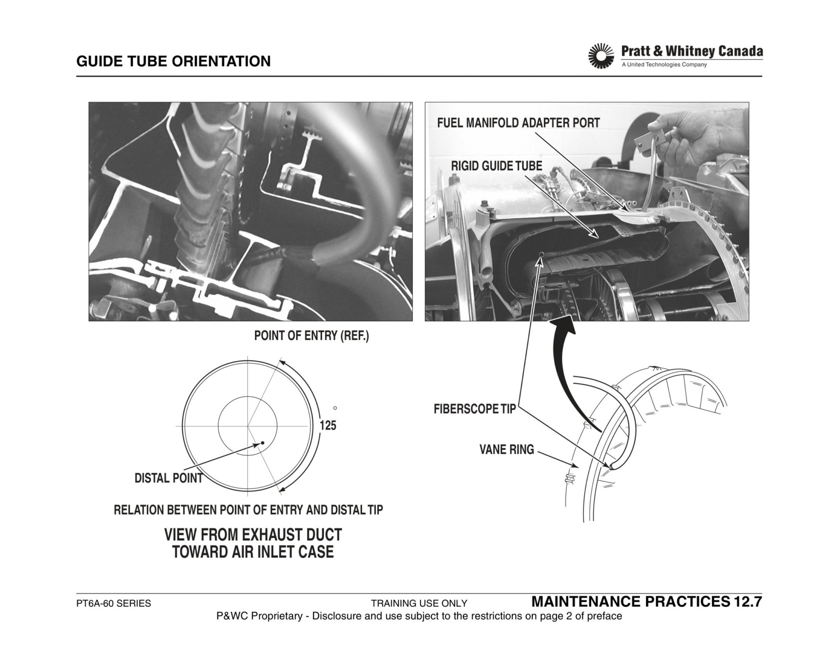
HOT SECTION TOOLS
1. Power Section Sling (Without The Propeller Installed On
The Engine) (PWC34673).
2. Compressor Turbine Holding Wrench (PWC30331).
3. Spacers (4) (PWC34478).
4. Spreader (PWC30335).
5. Compressor Turbine Puller (PWC30403).
6. Protector Sleeve (PWC30336).
7. Puller No. 2 Bearing Cover (PWC32823).
8. Dial Indicator (PWC 32280).
9. Shroud Grinder Adapter (PWC 32209).
10. Fuel Nozzle (PWC32811).
11. Grinder (PWC37918).
12. Crimper (PWC30458).
PT6A-60 SERIES
TRAINING USE ONLY
MAINTENANCE PRACTICES 12.8
P&WC Proprietary - Disclosure and use subject to the restrictions on page 2 of preface
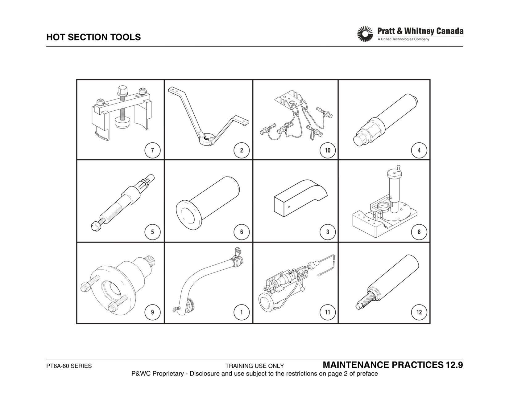
CT TIP CLEARANCE MEASUREMENT
Procedure:
- Measure tip clearance using a tapered or a wire feeler
gage, loading the CT disk in the direction of the mea-
surement.
- The tip clearance limits for each individual model is
listed in the Engine Maintenance Manual.
- No need to rotate turbine while taking measurements.
Limits Shown In The Maintenance Manual:
- Average clearance for new segments.
- Average clearance for used segment (that ran at least
5 minutes at take off power).
Amount Of Readings Taken:
- Average all readings and compare with limits stated in
Engine Maintenance Manual.
- For 10 segment types, take 3 readings per segment. (3
readings x 10 segments = 30 readings).
- For 20 segment types, take 2 readings per segment. (2
readings X 20 segments = 40 readings)
PT6A-60 SERIES
TRAINING USE ONLY
MAINTENANCE PRACTICES 12.10
P&WC Proprietary - Disclosure and use subject to the restrictions on page 2 of preface
HOT SECTION INSPECTION (CONT’D)
Inspection
CT Vane:
- Inspect vane ring for evidence of burning, cracking and
Gas Generator Case:
coating loss.
- Inspect case for cracks, distortion, corrosion and evi-
- Insure proper sliding fit (lugs to slots) with mating
dence of overheating.
parts.
- Inspect engine mount threads.
- Check air-cooling holes for blockage.
- Inspect P3 air supply holes at CT vane flange for
- Change ‘C’ & ‘W’ seal rings.
blockage.
- Inspect diffuser pipes for cracks and fretting wear.
- Inspect shanknuts at CT vane flange for security.
Shroud Housing:
- Inspect shroud housing for cracks, blockage of cooling
air holes, fretting wear at sealing ring contact area
Combustion Chamber Liners:
- Visually inspect the liners for evidence of burning,
cracking, buckling or metal to metal fretting wear.
Shroud Segments:
- Regap cooling rings if they are distorted.
- Inspect shroud segments for cracks, burning distortion
- Stop drilling of cracks and welding may be required
and metal buildup
(refer M/M for limits).
- Tip clearance
Small Exit Duct:
Compressor Turbine:
- Inspect for evidence of burning, cracking, buckling,
- Inspect CT blades for: tip rub, cracks, sulphidation,
coating loss or metal to metal fretting wear.
erosion, burning and coating loss.
- Stop drilling of cracks may be required (refer M/M for
- Inspect CT disk for damage.
limits)
- Wash turbine blades based on past sulphidation expe-
rience.
PT6A-60 SERIES
TRAINING USE ONLY
MAINTENANCE PRACTICES 12.12
P&WC Proprietary - Disclosure and use subject to the restrictions on page 2 of preface
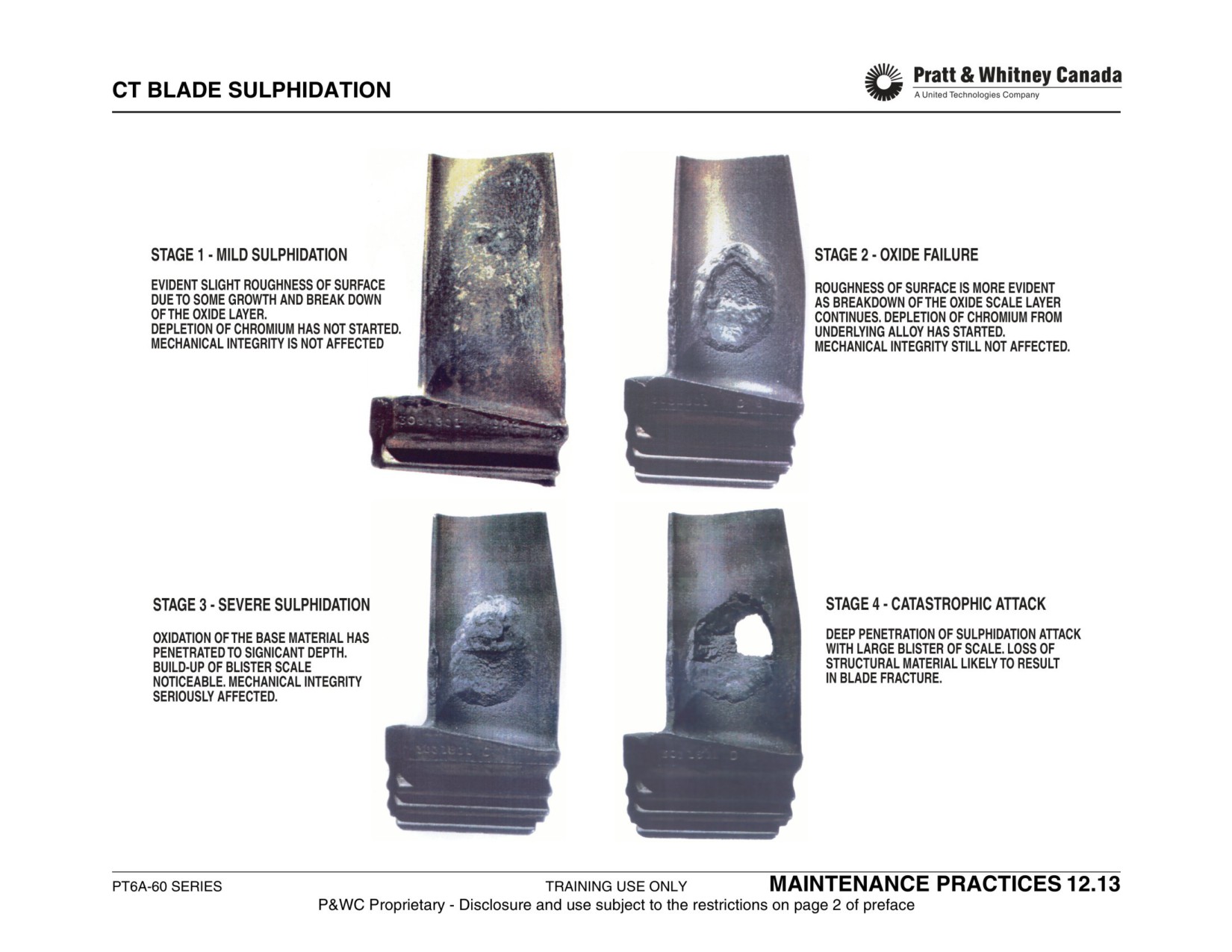
HOT SECTION INSPECTION (CONT’D)
Inter-Stage Sealing Ring:
Sealing surface restoration
- Inspect sealing ring(s) for fretting wear on sealing
diameter and face.
Purpose:
- Fit ring on sealing diameter for full contact.
To achieve best sealing of P3 in the gas generator case
area and keep leakage to a minimum.
Power Turbine Vane:
- Inspect vane ring for evidence of burning, cracking and
coating loss.
Description:
- Ensure proper sliding fit (lugs to slots) with PT stator
There are 2 sealing surface contacts that must be checked
housing.
for proper seating:
- Damage to the power turbine vane ring is not common
unless bad fuel nozzles caused damage to CT area.
1. Lock-plate to vane ring inner diameter.
2. Vane ring outer diameter to small exit duct.
Power Turbines:
Gas tight contact between these surfaces, depends on sur-
face finish and flatness. Surface finish should be better than
- Inspect the 1st and 2nd stage power turbines for:
32 micro-inches and .0005" max waviness. Lapping can be
cracks, burning, coating loss, corrosion, and impact
used to eliminate minor surface imperfections. When lap-
damage and blade shift.
ping is impractical, the assemblies should be machined at
- Return the power section to an authorized overhaul
an approved overhaul facility.
facility if either turbine needs to be replaced.
Exhaust Case:
- Inspect the case for general condition.
- Check the case for cracks near the flanges.
- Inspect flange -D- area for cracks around PT shroud.
PT6A-60 SERIES
TRAINING USE ONLY
MAINTENANCE PRACTICES 12.14
P&WC Proprietary - Disclosure and use subject to the restrictions on page 2 of preface
HOT SECTION INSPECTION (CONT’D)
Fitting Of Hot Section Parts
Step 2:
Purpose:
Install the shroud housing on a bench with the slots upper-
- To achieve best fitting of the hot section parts for mini-
most. Install the vane ring lugs inside the shroud housing
mizing side play which can result in CT tip rub.
lugs.
- To allow thermal expansion to take place, without any
binding.
Rotate the vane in the direction it would want to turn, as the
gases flow through it. Hold the shroud housing still. This
will force the lugs to contact the slots on one side and to
Description:
have a loose fit on the other side. Measure clearance on
both sides with a narrow feeler gage, ref. MM for limits.
There are 2 lug to slot fit areas that must be checked for
proper fit:
If clearance cannot be achieved, re-index the parts and
measure. If clearance can still not be obtained, remove
1. Vane ring inner lugs to #2 bearing cover slots.
material lightly with a stone until fit is achieved.
2. Vane ring outer lugs to shroud housing slots.
Step 1:
Install the vane ring on a bench with the inner lugs upper-
most. Install the #2 bearing cover slots around the vane
ring lugs.
Rotate the vane in the direction it would want to turn, as the
gas flow through it. Hold the #2 bearing cover still. This will
force the lugs to contact the slots on one side and to have a
loose fit on the other side. Measure clearance on both
sides with a narrow feeler gage, ref. MM for limits.
PT6A-60 SERIES
TRAINING USE ONLY
MAINTENANCE PRACTICES 12.15
P&WC Proprietary - Disclosure and use subject to the restrictions on page 2 of preface
HOT SECTION INSPECTION (CONT’D)
Shroud Segment Grinding
Preparations:
- Mask vane ring, #2 bearing and gas generator area
To achieve optimum Compressor Turbine tip clearance all
carefully.
around the shroud.
- Install the 4 rubber spacers with equal tension
between the large and small exit ducts.
- Install the grinder adapter on compressor stub shaft.
Hot Section Kit:
- Install the radius gage on the adapter and calculate
the tip clearance.
Operators who are equipped with the proper tooling can do
their own grinding. The preferred method is to send the hot
section kit to an approved P&WC service center, which can
Calculating Amount Of Metal Removed By Grinding
achieve a superior surface finish and concentricity control.
The hot section kit consists of the following:
The shroud inside dimension (radius) is measured by
- CT vane assembly (vane ring, small exit duct, shroud
comparing reference master tool to the shroud dimension.
housing and segments.
- #2 bearing cover and / or flange.
The dimension stamped on the master tool is the radius
- Lockplate.
from the center of the gage to the step on the master tool.
- Compressor turbine assembly.
Set gage dial to zero when it is on the master.
Grinding can be minimized by carefully selecting classes to
compensate for ovality or eccentricity of the shroud hous-
ing. The best fitting class segments is picked after measur-
ing the CT outside diameter and referring to a table from the
Engine Maintenance Manual. It is recommended to go 1-
class higher (thicker segments) to offset any excessive
ovality from the shroud housing.
PT6A-60 SERIES
TRAINING USE ONLY
MAINTENANCE PRACTICES 12.16
P&WC Proprietary - Disclosure and use subject to the restrictions on page 2 of preface
HOT SECTION INSPECTION (CONT’D)
Calculate Actual Tip Clearance Before Grinding As Fol-
lows:
(the numbers used are for examples only)
- Dimension stamped on side of
- gauge (master).= 4.282"
- Dial gage reading.= -0.009"
(plus or minus sign is important)
- CT largest diameter / 2 (8.532 / 2).= 4.266"
Step 1 = Find the radius of the shroud:
(master + dial reading => 4.282" -.009")= 4.273"
Step 2 = Find actual CT tip clearance:
(shroud radius - disk radius => 4.273" - 4.266")
= 0.007"
Step 3 = Determine material to be removed, assuming
required tip clearance is .010".
(actual clearance - required clearance :
.007" - .010")
= -.003"
We need to grind .003" off the segments.
Note:
Refer to Maintenance Manual for proper grinding proce-
dure.
PT6A-60 SERIES
TRAINING USE ONLY
MAINTENANCE PRACTICES 12.17
P&WC Proprietary - Disclosure and use subject to the restrictions on page 2 of preface
HOT SECTION INSPECTION (CONT’D)
Fuel Nozzle Functional Check:
Pressure Test:
Pressure test for leakage between nozzle tip and adapter at
Ensures the engine combustion chamber receives properly
500 PSIG fluid pressure or 200 PSIG air pressure, no leak-
atomized fuel.
age allowed.
Inspection Interval:
Fuel Nozzle Cleaning:
- 200 hours for new operators.
- When spraying, brush tip with a non-metallic brush to
- 400 hours max interval afterwards, depending of con-
loosen any possible carbon debris.
dition.
- If above method is not effective, ultrasonically clean
nozzles in carbon remover solvent.
- Always rinse nozzles in hot water after cleaning, since
Spray Pattern Check:
carbon solvent is corrosive.
- Flow test for spray pattern at 20 PSI. Check for drool-
ing and spitting (none permitted).
- There may be an onion or tulip shaped spray pattern.
Fuel Nozzle Sheaths:
- Flow test for spray pattern at 60 PSI. Check for spray
- Inspect sheaths for erosion on the dome top.
pattern streakiness, drooling or spitting.
- Inspect sheaths for wear at combustion chamber con-
- 20% max streakiness is allowed
tact area.
- Check gap between sheath and adapter flange.
- Check concentricity between sheath and adapter ori-
Note 1:
fice with a .020" drill.
All values are for reference only. Always refer to the appro-
priate Maintenance Manual for proper settings.
Note 2:
If a streaking nozzle is found during testing, a visual HSI or
borescope inspection of the hot section should be done.
PT6A-60 SERIES
TRAINING USE ONLY
MAINTENANCE PRACTICES 12.18
P&WC Proprietary - Disclosure and use subject to the restrictions on page 2 of preface
HOT SECTION INSPECTION (CONT’D)
T5 System Functional Check:
Heat Response Test: (T5 Probe Functional Check)
T5 system inspection should be performed during hot sec-
This check is done to verify proper functioning of T5 probes.
tion inspection with the engine split at flange "C" or when-
Ensures T5 probes respond to heat.
ever a T5 indication problem is suspected.
With engine split at "C" flange, connect test set to alumel
and chromel lead. Heat each probe individually and verify
Continuity Resistance (Loop) Check:
response. Replace faulty thermocouple probe.
Ensures continuity and proper resistance in the T5 probes,
bus-bars, wires and terminals.
Note:
- Each T5 probe can be checked for loop and insulation
Disconnect all leads from T5 terminal block on gas genera-
resistance if a fault is suspected.
tor case (use care, while disconnecting leads, to avoid
- Always clean connector carefully to ensure resistance
cracking the insulation material) and measure resistance
of the system is not disturbed
between Alumel and Chromel terminals.
Disconnect T5 probes from bus-bar and measure resis-
Trim Thermocouple Check:
tance between Alumel and Chromel terminals, refer to
Maintenance Manual for resistance limits.
This check is done to ensure proper resistance of the trim
stick.
Insulation (Ground) Resistance Check:
This check is done to ensure system is not grounded
(shorted). Ensures that neither Alumel nor Chromel bus
bars are contacting the casing.
Connect test set between alumel or chromel and ground
(gas generator case) and measure insulation resistance.
Minimum resistance must not be less than specified limit.
PT6A-60 SERIES
TRAINING USE ONLY
MAINTENANCE PRACTICES 12.19
P&WC Proprietary - Disclosure and use subject to the restrictions on page 2 of preface
RIGGING
RIGGING
PT6A-60 SERIES
TRAINING USE ONLY
RIGGING 13.1
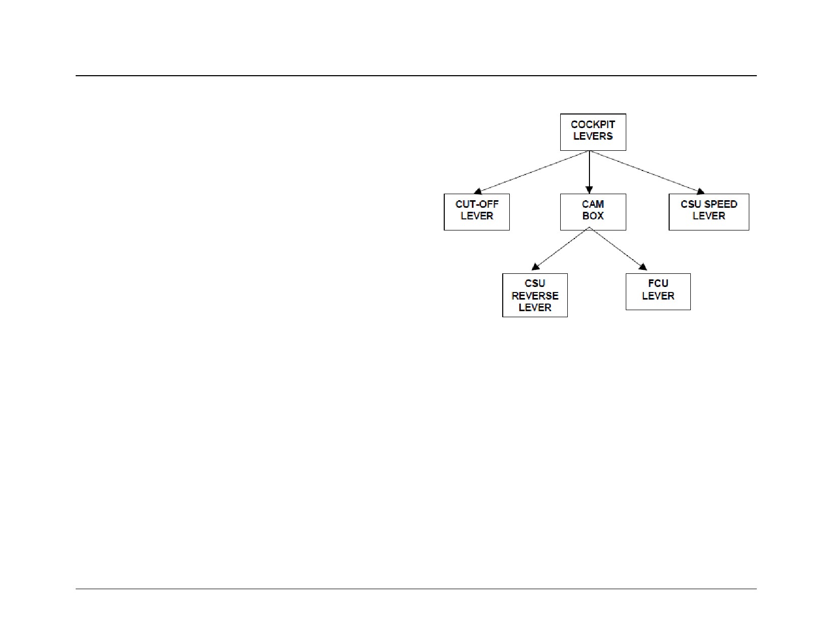
BASIC ENGINE RIGGING
Purpose:
Provide the operator with a basic approach to engine rig-
ging. This section defines the logical sequence that should
be followed when rigging the engine. It also describes the
post run-up adjustments necessary to get an ideal cockpit
lever to engine response relationship. Use the airframe
maintenance manual for specific engine rigging information.
Pre-Rigging Verification:
- Ensure that cockpit levers and cables operate freely
and do not bind before connecting it to the engine.
- Ensure that the engine reversing cable is not damaged
and operates freely when disconnected from the beta
lever.
- Verify that the propeller reversing lever is connected to
the beta valve and make sure the carbon block is in
good condition.
- Verify that the beta valve is properly connected to the
beta lever.
- Verify run-out on beta feedback slip ring (.003 max)
- Check that beta valve slides freely.
You are now ready to rig the engine.
PT6A-60 SERIES
TRAINING USE ONLY
RIGGING 13.2
REAR LINKAGE RIGGING
One of the first steps prior to rigging the fuel control unit on
Note:
the PT6 is to carefully rig the cambox position. Once this is
A “rig pin" hole located on the cambox may be used to facil-
done, the fuel control unit and the reversing cable can be
itate the track point rigging. Ensure that the above proce-
rigged.
dure applies for a more precise rigging.
Cambox Rigging:
With the airframe power lever cable and the engine reverse
cable disconnected from the cambox, move the cockpit
power lever through the full range and verify motion is free
of binding and excessive friction.
- The next step is to find the track point.
- Cycle the power lever forward and back slowly until the
cockpit idle detent is contacted.
- Find the track point by rotating the cambox input lever
counterclockwise until the reverse cam moves back 1/
32 inch (apply light forward force on reversing cam
while measuring).
- Once the track point is located, position the cambox
input lever at the angle specified by the airframe man-
ufacturer.
- Cycle the cockpit power lever between maximum for-
ward and reverse position and ensure the power lever
cable terminal travel exceeds the required input l lever
displacement.
- Connect the airframe power lever cable to the cambox
input lever
PT6A-60 SERIES
TRAINING USE ONLY
RIGGING 13.3
WOODWARD FUEL CONTROL RIGGING
1. Disconnect the FCU interconnecting rod and set it's
length to 1/8 inch shorter than specified in the airframe
maintenance manual (the rod length will be rectified later
on).
2. With the rod disconnected position the fuel lever to con-
tact the idle stop without going into the deadband.
3. Connect the FCU inter connecting rod to the proper hole
on the FCU actuating lever. Connect the rear end of the
rod to the FCU arm using the serrated washer to posi-
tion the FCU shaft as marked in step 2 (at the idle stop).
4. Remove FCU interconnect rod and lengthen it 1/8 inch
(so it goes back to airframe manual recommendation).
This will provide some forward deadband (approximately
1/4 inch) on the pedestal before Ng picks up.
5. Move the power lever through the full range (make sure
the reverse cable is disconnected). The cam follower
pin should not bottom out at either end of the reverse
cam slot. In the maximum forward position, the FCU
maximum Ng stop screw should contact the FCU maxi-
mum stop.
PT6A-60 SERIES
TRAINING USE ONLY
RIGGING 13.4
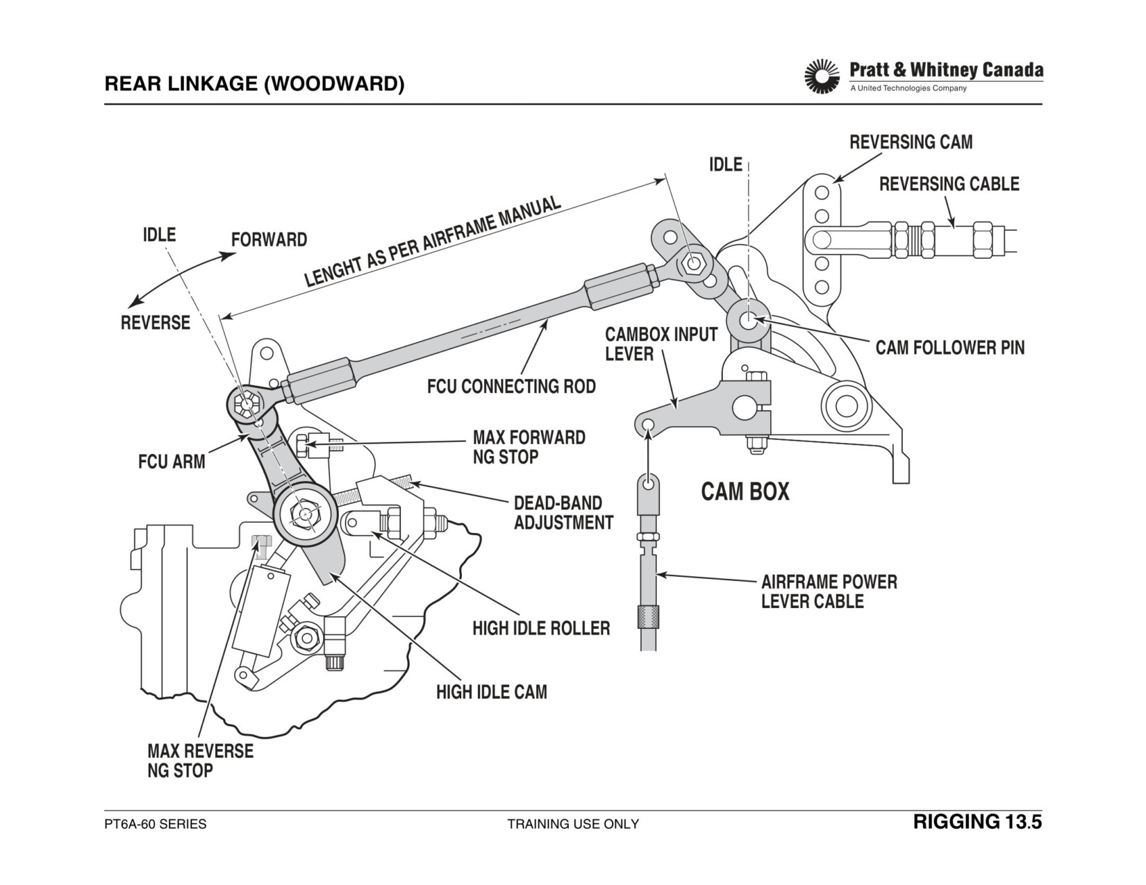
FRONT LINKAGE RIGGING
Telescopic Interconnect Rod:
Rigid Interconnect Rod:
1. Disconnect the reverse cable at the cambox.
1. Disconnect the reverse cable at the cambox.
2. Move the Power Lever in the cockpit between Flight Idle
2. Move the cockpit power lever between idle and maximum
and Max Power setting to verify free movement.
power position to verify free movement
3. Pull on the Beta Lever and adjust the front clevis so that
3. Disconnect the propeller governor interconnect rod, pull
the Beta Valve clevis slot face is flush with the Beta Valve
on the beta lever and adjust the front clevis so that the
cap.
beta valve clevis slot face is flush with the beta valve nut.
4. Adjust the length of the interconnect rod to get the
4. Connect the reverse cable rear clevis to the required hole
required gap as specified in the Airframe Maintenance
in the reverse cam. Adjust the clevis so that the cable is in
manual.
light compression (pushed forward) when the clevis pin is
installed.
5. Cycle the cockpit levers from idle to max power to verify
smooth operation. Adjust the reverse cable pre-load at
5. Connect the CSU interconnect rod in the specified holes
the rear clevis connection if excessive friction is
and adjust it to get a sliding fit, then shorten thread by
observed. The reverse cable will be in tension since it is
turning one end 1/2 turn.
pushed forward by the Beta valve spring.
6. Cycle the cockpit power lever from idle to maximum to
confirm smooth motion. Adjust the reverse cable pre-load
at the rear clevis connection if excessive friction is
observed.
PT6A-60 SERIES
TRAINING USE ONLY
RIGGING 13.6
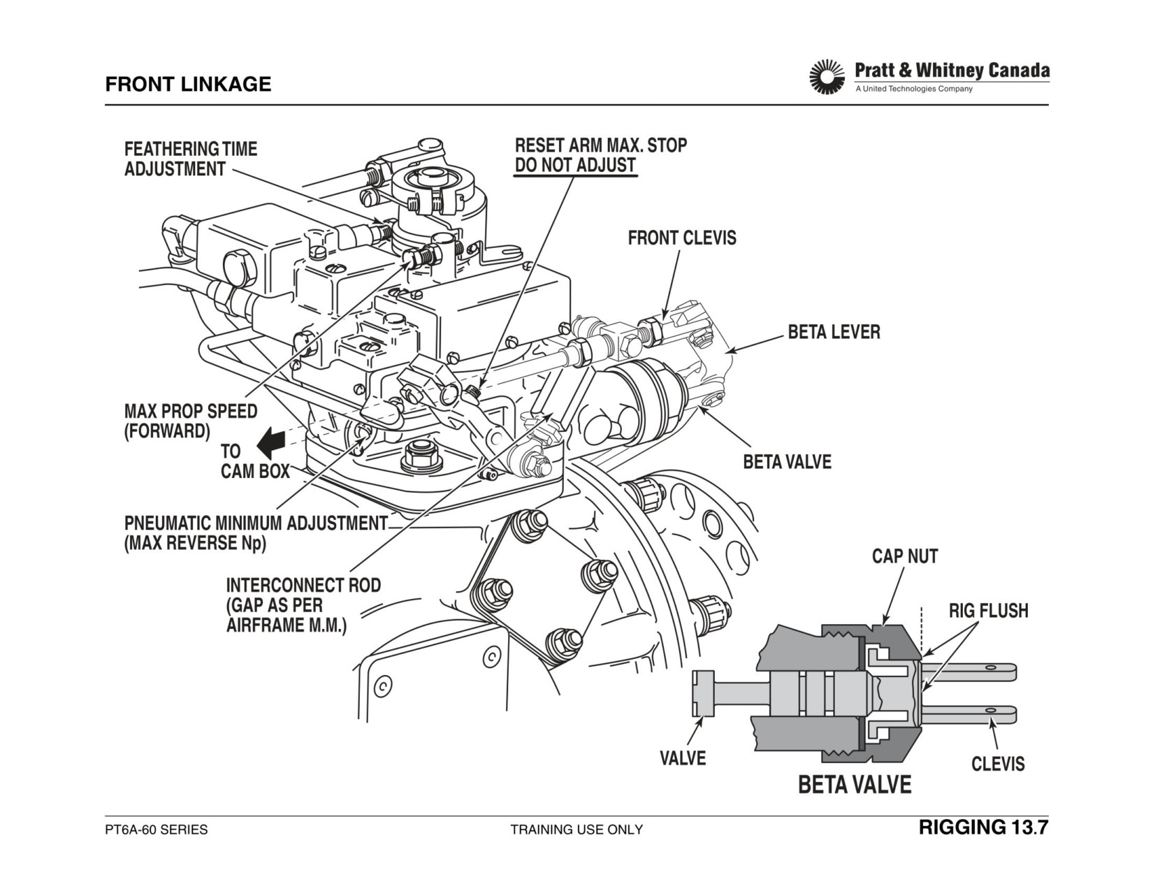
FUEL CONDITION LEVER
- Disconnect control cable from the fuel idle reset/cut-
Propeller Lever:
off lever
- Move the cockpit propeller lever fully forward. Ensure
- Insert rigging pin through the idle reset/cut-off lever
that speed select lever contacts maximum Np stop
- Place cockpit fuel condition lever to ground idle and
screw. Adjust console stop to comply.
adjust the aircraft cable to fit to the appropriate hole on
- Move cockpit propeller lever to feather. Ensure speed
the idle reset/cut-off lever
select lever fully depresses the feathering valve
- Remove rigging pin
plunger.
Ensure :
Note:
- Fuel condition lever moves freely throughout the entire
Speed select levers should be loaded slightly against the
range
maximum Np when maximum propeller speed is selected.
At Cut-Off Position :
Post Rigging Check:
- Ensure that there is a positive contact with the cut-off
stop.
Ensure the propeller feathers when the cockpit propeller
- Ensure that the unloading valve screw fully depresses
lever is halfway through the feather detent.
the unloading valve plunger.
At High Idle Position :
- Ensure high idle stop is contacted
Prior To Starting The Engine:
- Disconnect the fuel line going to the flow divider
- Perform a wet motoring run to confirm Positive fuel
cut-off
- Ensure cut-off happens when the fuel lever position is
halfway through the cut-off detent.
- Check low and high idle speed as per aircraft mainte-
nance manual
PT6A-60 SERIES
TRAINING USE ONLY
RIGGING 13.8
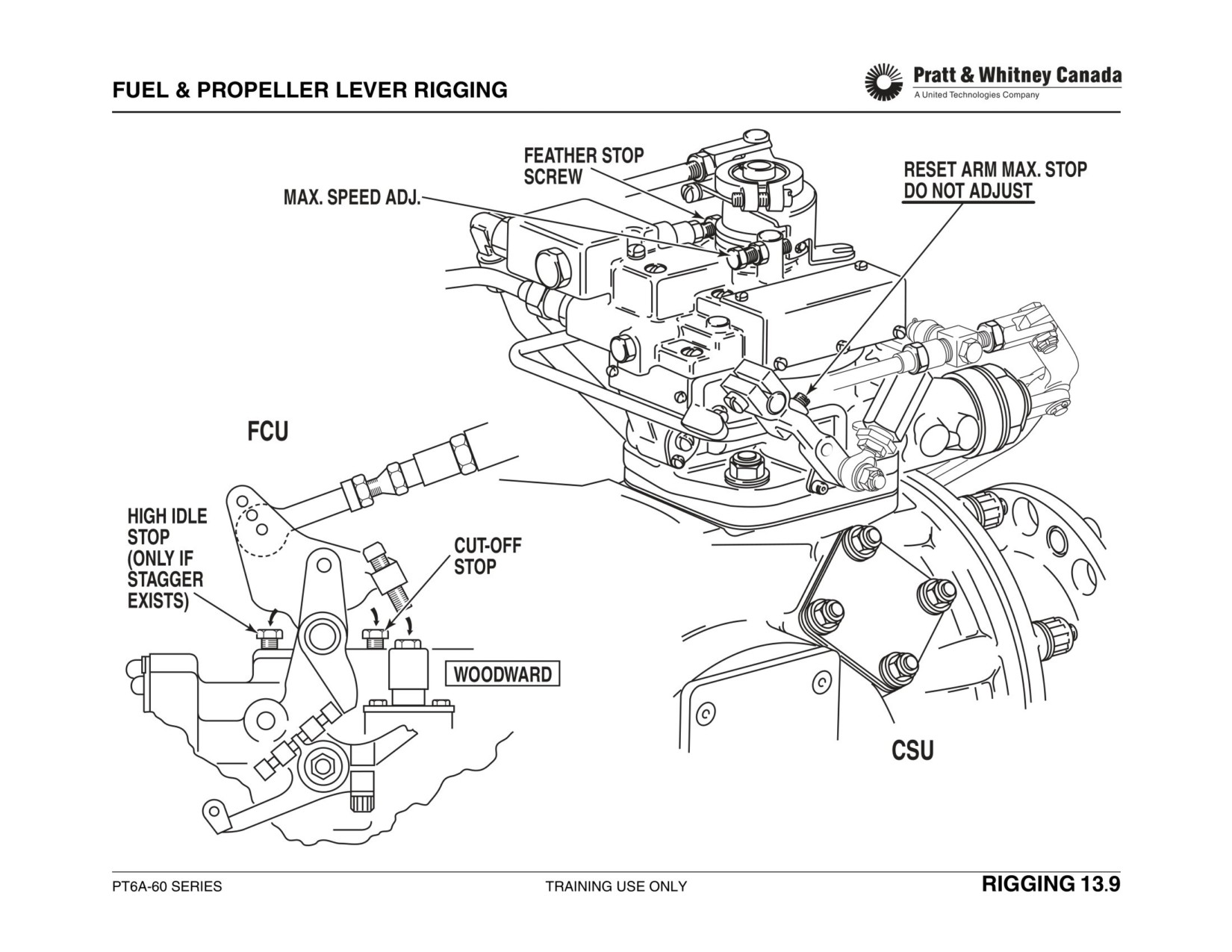
POST RUN UP ADJUSTMENTS
Prior to running the engine ensure that:
- The FCU maximum Ng stop is contacted when the cockpit power lever is advanced to the maximum position.
- The cut-off stop is contacted when the condition lever is at the cut-off position.
- The speed select lever on the CSU makes firm contact with the maximum speed stop.
Symptom
Fix
- Ensure rigging was done properly
Idle Ng Too High
- Adjust Ng speed as per manual’s instructions
- Ensure there are no P3 or Py leaks
Idle Ng Too Low
- Adjust as per manual instructions
Before adjusting make sure that:
- The deadband is the same on the two engines
- The power lever travel movement from idle to take off is the same on the
Ng Pick-Up Point Is Different On
two engines (stagger is constant).
The Two Engines
To Adjust:
(Constant Stagger)
- To move the pick-up point forward on the quadrant, turn the serrated
washer clockwise. (Do not change the rod length) NB: 2 teeth change on
serrated washer = .040" movement on the cockpit quadrant approximately.
Before adjusting
- Ensure low and high idle speeds are the same on both engines
Unequal Power Lever Travel
- Ensure maximum Np is the same on both engines.
Movement From Idle To Take Off
To Adjust:
Between The Two Engines
- To shorten the power lever travel, (PLA ahead) shorten FCU interconnect-
(Progressive Stagger)
ing rod
- Reposition the pick-up point by adjusting the serrated washer (counter-
clockwise in this case)
PT6A-60 SERIES
TRAINING USE ONLY
RIGGING 13.10
POST RUN UP ADJUSTMENTS (CONT’D)
Symptom
Fix
- Verify position of the beta valve is identical on the two engines when the
cockpit power lever is advanced halfway between idle and maximum
power.
Primary Blade Angle Check; Different
- Adjust beta valve position using the reversing cable clevis end (small
Torque On The Two Engines
adjustment) or adjust beta nuts if airframe maintenance manual permits
(big adjustment)
- Send propeller to an overhaul shop if beta nuts adjustment is not
allowed. Beta valve position has a limited effect on PBA.
- Confirm the beta valve position is flush with the beta valve cap nut.
- Ensure the reverse cable clevis is connected to the specified reverse
Propeller Zero Pitch Position (Np
cam hole.
Increase In Rearward Deadband) Is
- Ensure the cambox track point is rigged the same on the two engines.
Staggered On The Two Engines
- Perform primary blade angle check (Calibrate torque transducer). Adjust
PBA as required
- Verify track point rigging
Pilot Reports YAW During Approach
- Verify beta valve rigging
- Perform primary blade angle check
PT6A-60 SERIES
TRAINING USE ONLY
RIGGING 13.11
TWIN ENGINE RIGGING TROUBLESHOOTING
Condition 1
Ideal Condition.
Condition 5
Reverse Pick-Up Point Are Split
- Adjust deadband screw on the right hand engine
May vary from airframe to airframe. The Airframe Mainte-
(CCW) to reduce the band. This will change the dead-
nance manual provides a description of the required set-
band in forward as well.
tings after engine rigging.
- Reposition the deadband using the serrated washer
(.003” feeler gauge test). Start engine and re-adjust
the idle speed.
Condition 2
Ng Pick-Up And Target Points Are Split.
- Displace the pick-up point with the serrated washer.
This will also bring the power lever more or less in line.
Condition 6
Beta Valve Tracking Point Is Staggered
- Also the deadband must be adjusted.
(Np increases in Beta).
- Verify the Cambox reverse “track point” is rigged cor-
rectly.
Condition 3
Power Lever Stagger For Equal Torque
- Verify “pre-loading” of pin connecting the reverse cam
- Correct the stagger by lengthening the FCU intercon-
and the clevis.
necting rod on the right hand side engine.
- This will move the pick-up point forward which can be
corrected by adjusting the serrated washer on the right
Condition 7
Forward & Reverse Pick-Up Point Not
hand side engine.
Matched
- Move deadband using serrated washer (but do not
adjust angle) rearward on right engine
Condition 4
Ng Pickup Point Split But Equal At
- Use paper check to have both engines at same posi-
Power.
tion
- Lengthen the FCU interconnect rod on the right hand
side engine.
- Adjust deadband screw (.003” gauge test) and the ser-
rated washer to set the “deadband angle” and “pick-up
point position” the same on both engines.
- Start engine and verify the idle speed.
PT6A-60 SERIES
TRAINING USE ONLY
RIGGING 13.12
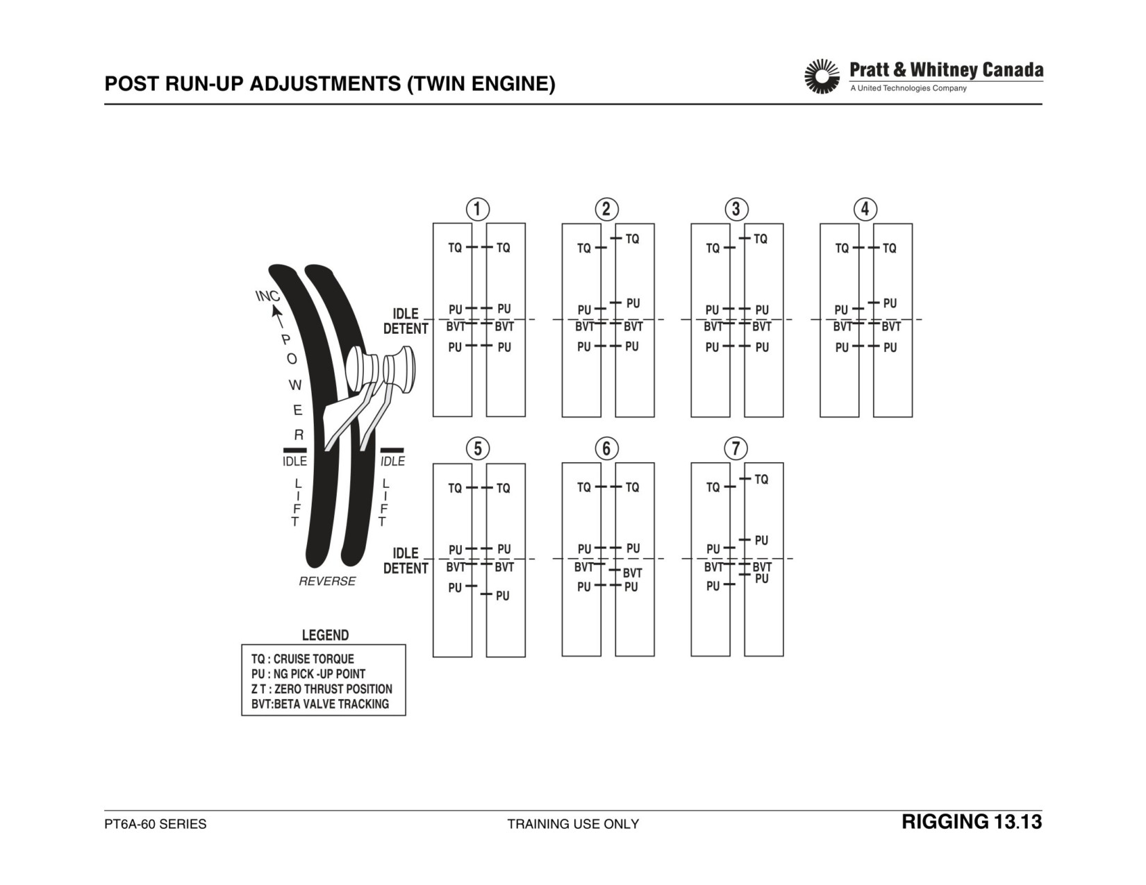
TRAINING MATERIAL CHANGE REQUEST
Date: ________________________________
Company Name and Address: ____________________________________________________________________________
Your Name: __________________________________
Job Title:_________________________________________
Training Aid Title:_______________________________________________________________________________________
Reference Page(s): _____________________________________________________________________________________
Recommended Change(s) and Reason(s) for Change(s):_______________________________________________________
_____________________________________________________________________________________________________
_____________________________________________________________________________________________________
____________________________________________________________________________________________________
TMCR ID Number (P&WC Office Use Only): _________________________________________________________________
Send To:
Note: If you would like to be contacted regarding the
Pratt & Whitney Canada Customer Training
resolution of your request for change, please provide us
1000 Marie-Victorin (05CA1)
with your telefax number on the following line.
Longueuil, Quebec, Canada, J4G 1A1
Email: customer.training@pwc.ca
Telefax Number: _________________________________
PT6A-60 SERIES
TRAINING USE ONLY
RIGGING 13.14