Engine PT6A-60 SERIES. TRAINING MANUAL (2007) - page 1
PREFACE
PT6A-60 SERIES
TRAINING MANUAL
November 2007
Pratt & Whitney Canada
STUDENT: ________________________________
INSTRUCTOR:_____________________________
PT6A-60 SERIES
TRAINING USE ONLY
PREFACE I
P&WC Proprietary - Disclosure and use subject to the restrictions on page 2 of preface
DISCLOSURE
WARNING - PROPRIETARY RIGHTS NOTICE
This document is the property of Pratt & Whitney Canada Corp. “(P&WC)”. You may not possess,
use copy or disclose this document or any information in it, for any purpose, including without
limitation to design, manufacture or repair parts, or obtain FAA or any other government approval
to do so, without P&WC’s express written permission. Neither receipt or possession of this docu-
ment alone, from any source constitutes such permission. Possession, use, copying or disclo-
sure by anyone without P&WC’s express written permission is not authorized and may result in
criminal or civil liability
NOTICE - DISCLOSURE OF INFORMATION
This document contains trade secrets or other confidential information, the further disclosure of
which may be harmful to Pratt & Whitney Canada Corp. if the head of a government agency or
department intends to disclose any of this information, written notice should be given to: the Vice
President - Legal Services, Pratt & Whitney Canada Corp., 1000 Marie Victorin (01BE5), Longueuil,
Quebec J4G 1A1
PRATT & WHITNEY CANADA
The Customer Training Centre, Pratt and Whitney Canada, Longueuil, Quebec, Canada issued this document. This
document is to be used for Training Use Only. The data contained herein does not replace or supersede the information
contained in the appropriate airframe or engine maintenance manuals or other official publications.
For information concerning this manual, contact the P&WC Customer Training Department, by :
Tel: 1-450-468-7774, Fax: 1-450-468-7824, or Email: customer.training@pwc.ca
P&WC Customer Training course schedule and registration on Internet: http://www.pwccustomertraining.ca
For technical queries, contact the P&WC technical support Customer First Centre (CFC) (24 HOUR SERVICE):
Telephone : (USA & Canada)1-800-268-8000
International Direct Access :1-8000-268-8000
General :1-450-647-8000
Fax :1-450-647-2888
Pratt & Whitney Canada on the Internet : http://www.pwc.ca
TABLE OF CONTENT
PREFACE
I
COMPRESSOR INLET CASE
2.6-2.7
DISCLOSURE
II
COMPRESSOR
2.8-2.9
PRATT & WHITNEY CANADA
III-IV
COMPRESSOR WASH
2.10-2.11
TABLE OF CONTENT
V-VIII
COMPRESSOR BLEED VALVE
2.12-2.15
PRE-SWIRL SYSTEM
2.16-2.19
INTRODUCTION
IX
BLEED VALVE CLOSING POINT
2.20-2.23
SCOPE
X
GAS GENERATOR CASE
2.24
ABBREVIATIONS
XI
GAS GENERATOR CASE / DIFFUSER
2.25
ENGINES COVERED IN THIS MANUAL
XII
COLD SECTION TROUBLESHOOTING
2.26
PT6 GENERAL NOTES
XIII
MAJOR ENGINE DIFFERENCES
XIV-XV
CHAPTER 3 - COMBUSTION & TURBINE
3.1
P&WC PUBLICATIONS
XVI
HOT SECTION
3.2
PUBLICATION STANDARDS
XVII-XVIII
HOT SECTION AREA
3.3
SERVICE BULLETIN COMPLIANCE CODES
XIX
COMBUSTION CHAMBER LINER
& SMALL EXIT DUCT
3.4-3.5
CHAPTER 1 - ENGINE OVERVIEW
1.1
COMPRESSOR TURBINE VANE RING
3.6-3.9
PT6A-61 RIGHT FRONT VIEW
1.2
COMPRESSOR TURBINE
3.10-3.11
PT6A-64 LEFT FRONT VIEW
1.3
COMPRESSOR TURBINE TRIM BALANCING... 3.12
PT6A-60 RIGHT FRONT VIEW
1.4
COMPRESSOR TURBINE
3.13
PT6A-67 LEFT VIEW
1.5
ALTERNATE TRIM WEIGHTS (64/66/67)
3.14
MAJOR ASSEMBLIES AND FLANGES
1.6-1.7
ALTERNATE TRIM WEIGHTS
3.15
FEATURES
1.8
POWER TURBINE VANE RINGS
3.16-3.17
GENERAL TURBOPROP OPERATION
1.10
POWER TURBINES
3.18-3.19
TURBOPROP ENGINE
1.11
TURBINE WASH
3.20-3.21
MAIN ENGINE BEARINGS
1.12
EXHAUST DUCT & PT SHAFT HOUSING
3.22-3.23
BEARINGS
1.13
HOT SECTION SEALING
3.24-3.27
STATIONS
1.14-1.15
HOT SECTION TROUBLESHOOTING
3.28
ENGINE EXTERNAL COMPONENTS
1.16-1.19
CHAPTER 2 - COMPRESSOR SECTION
2.1
COMPRESSOR SECTION
2.2-2.3
INERTIAL SEPARATOR (AIRFRAME)
2.4
INERTIAL SEPARATOR (TYPICAL)
2.5
PT6A-60 SERIES
TRAINING USE ONLY
TABLE OF CONTENT V
P&WC Proprietary - Disclosure and use subject to the restrictions on page 2 of preface
TABLE OF CONTENT (CONT’D)
CHAPTER 4 - GEARBOXES
4.1
CHAPTER 8 - IGNITION SYSTEM
8.1
REDUCTION GEARBOX
4.2-4.3
IGNITION SYSTEM
8.2-8.3
STANDARD ROTATION REDUCTION GEARBOX4.4
PT6A-66 REVERSE ROTATION GEARBOX
4.5
CHAPTER 9 - PERFORMANCE
9.1-9.2
ACCESSORY GEARBOX
4.6-4.7
ENGINE PERFORMANCE CHECK (TYPICAL)9.3
PIN LOCK ARRANGEMENT
4.8
PERFORMANCE CHECK (SHORTS INSTALL)9.4-9.6
ACCESSORY GEARBOX
4.9
WebECTM
9.7-9.8
ECTM SAMPLE PLOT
9.9
CHAPTER 5 - OIL SYSTEM
5.1-5.7
TBO & HSI INTERVAL
9.10
OIL PRESSURE REGULATION & FILTRATION..
5.8-5.9
OPERATING LIMITS*
9.11-9.18
THERMOSTATIC BYPASS
ROTOR COMPONENTS - SERVICE LIFE
9.19
& CHECK VALVE
5.10-5.11
OVERTORQUE CHART (TYPICAL)
9.20
OIL SYSTEM TROUBLESHOOTING
5.12-5.13
OVERTEMPERATURE CHART (TYPICAL)
9.21
ENGINE TROUBLESHOOTING
9.22
CHAPTER 6 - SECONDARY AIR SYSTEM
6.1-6.3
PERFORMANCE TROUBLESHOOTING
9.23-9.27
ACCESSORY GEARBOX BREATHER
6.4-6.5
OIL TANK PRESSURIZING VALVE
6.6-6.7
CHAPTER 10 - FUEL SYSTEM
10.1
TURBINE COOLING
POWER MANAGEMENT
10.2-10.3
AND AIRBLEED SYSTEM
6.8-6.9
FUEL SYSTEM
10.4-10.6
BEARING COMPARTMENT SEALING
6.10-6.11
FUEL SYSTEM SCHEMATIC
10.7
FUEL HEATER
10.8-10.9
CHAPTER 7 - ENGINE INDICATING SYSTEM ..
7.1-7.3
FUEL PUMP
10.10-10.11
INTER-TURBINE TEMPERATURE (T5)
7.4
FUEL CONTROL UNIT (MAIN FLOW)
10.12-10.13
TEMPERATURE INDICATING SYSTEM (T5)
7.5
FUEL METERING SECTION
10.14-10.15
TEMPERATURE INDICATING SYSTEM (ITT)
7.6
METERING SECTION (3D CAM)
10.16
T5 SYSTEM SCHEMATIC
7.7
FUEL CONTROL SYSTEM
10.17
TORQUE SYSTEM
7.8-7.9
COMPRESSOR DELIVERY AIR LINES
10.18
CHIP DETECTOR
7.10-7.11
P3 AIR FILTER ELEMENT
10.19
FLOW DIVIDER WITH DUMP VALVE
10.20-10.21
FLOW DIVIDER WITH PURGE VALVE
10.22-10.23
FLOW DIVIDER WITH DUMP VALVE
10.20-10.21
PT6A-60 SERIES
TRAINING USE ONLY
TABLE OF CONTENT VI
P&WC Proprietary - Disclosure and use subject to the restrictions on page 2 of preface
TABLE OF CONTENT (CONT’D)
FLOW DIVIDER WITH PURGE VALVE
10.22-10.23
HOT SECTION TOOLS
12.8-12.9
SIMPLEX FUEL NOZZLES
10.24-10.25
CT TIP CLEARANCE MEASUREMENT
12.10
DUPLEX FUEL NOZZLES
10.26-10.27
HOT SECTION INSPECTION (CONT’D)
12.12
FUEL CONTROL UNIT MANUAL OVERRIDE .10.28
CT BLADE SULPHIDATION
12.13
FCU MANUAL OVERRIDE
10.29
HOT SECTION INSPECTION (CONT’D)
12.14-12.19
POWER RECOVERY SYSTEM
10.30-10.31
OVERTORQUE LIMITER
10.32-10.33
CHAPTER 13 - RIGGING
13.1
FUEL CONTROL UNIT ADJUSTMENT
10.34-10.35
BASIC ENGINE RIGGING
13.2
FUEL SYSTEM
REAR LINKAGE RIGGING
13.3
TROUBLESHOOTING SUMMARY
10.36
WOODWARD FUEL CONTROL RIGGING
13.4
REAR LINKAGE (WOODWARD)
13.5
CHAPTER 11- PROPELLER SYSTEM
11.1-11.3
FRONT LINKAGE RIGGING
13.6
PITCH CHANGE MECHANISM
11.4-11.5
FRONT LINKAGE
13.7
PROPELLER GOVERNOR
FUEL CONDITION LEVER
13.8
GOVERNING MODE
11.6-11.7
FUEL & PROPELLER LEVER RIGGING
13.9
PROPELLER GOVERNOR
11.8
POST RUN UP ADJUSTMENTS
13.10-13.11
BETA MODE (FORWARD OPERATION)
11.9
TWIN ENGINE RIGGING
PROPELLER GOVERNOR
11.10-11.12
TROUBLESHOOTING
13.12
BETA MODE (REVERSE OPERATION)
11.13
POST RUN-UP ADJUSTMENTS
PROPELLER FEATHERING
11.14-11.15
(TWIN ENGINE)
13.13
NF GOVERNOR
11.16-11.17
PROPELLER OVERSPEED GOVERNOR
11.18-11.19
PROPELLER GOVERNOR
ADJUSTMENTS
11.21-11.23
PRIMARY BLADE ANGLE (PBA) CHECK
11.24
PRIMARY BLADE ANGLE CHART
11.25
PROPELLER SYSTEM TROUBLESHOOTING11.26
CHAPTER 12 - MAINTENANCE PRACTICES.12.1
PERIODIC INSPECTION
12.2-12.3
HOT SECTION INSPECTION
12.4
BORESCOPE INSPECTION
12.6
GUIDE TUBE ORIENTATION
12.7
PT6A-60 SERIES
TRAINING USE ONLY
TABLE OF CONTENT VII
P&WC Proprietary - Disclosure and use subject to the restrictions on page 2 of preface
BLANK PAGE
PT6A-60 SERIES
TRAINING USE ONLY
TABLE OF CONTENT VIII
P&WC Proprietary - Disclosure and use subject to the restrictions on page 2 of preface
INTRODUCTION
INTRODUCTION
PT6A-60 SERIES
TRAINING USE ONLY
INTRODUCTION IX
P&WC Proprietary - Disclosure and use subject to the restrictions on page 2 of preface
SCOPE
This training guide contains information pertaining to the
description, operation, maintenance and troubleshooting of
the PT6A-52 /60A / 60AG / 61 / 64 / 65AG / 65AR / 65B /
65R / 66 / 66A / 66B / 66D / 67 / 67A / 67AF / 67AG / 67AF
/ 67AR / 67B / 67D / 67F / 67P /67R engines. This training
guide is intended for training use only and includes cross
section drawings, schematics and text.
A basic understanding of jet engine principle would be an
asset.
This guide may be used for Line Maintenance or Heavy
Maintenance training.
PT6A-60 SERIES
TRAINING USE ONLY
INTRODUCTION X
P&WC Proprietary - Disclosure and use subject to the restrictions on page 2 of preface
ABBREVIATIONS
AG
Agricultural
Palt
Pressure Altitude
AGB
Accessory Gearbox
Pamb
Ambient Air Pressure
AMM
Airframe Maintenance Manual
PBA
Primary Blade Angle
BOV
Bleed Off Valve
PLA
Power Lever Angle
CCW
Counterclockwise
PPH
Pounds Per Hour
CW
Clockwise
PSI
Pounds Per Square Inch
CSU
Constant Speed Unit (Prop Governor)
PSIA
Pounds Per Square Inch Absolute
CT
Compressor Turbine
PSID
Pounds Per Square Inch Differential
ECTM
Engine Condition Trend Monitoring
PSIG
Pounds Per Square Inch Gage
ESHP
Equivalent Shaft Horsepower
PT
Power Turbine
FCU
Fuel Control Unit
Px
Modified P3, After A Restrictor
FI
Flight Idle (High Idle)
Py
Modified Px, After A Restrictor
FOD
Foreign Object Damage
RGB
Reduction Gearbox
GI
Ground Idle (Low Idle)
S/N
Serial Number
HSI
Hot Section Inspection
SB
Service Bulletin
IAS
Indicated Air Speed
SIL
Service Information Letter
IBR
Integrally Bladed Rotor
SFC
Specific Fuel Consumption
ISA
International Standard Atmosphere
SHP
Shaft Horsepower
ITT
Interturbine Temperature (T5)
T/O
Take-Off
MM
Maintenance Manual
T5
Temperature At Station 5 (ITT)
MOP
Main Oil Pressure
TBO
Time Between Overhaul
MOT
Main Oil Temperature
Tq
Torque
Nf
Free Turbine Speed
Wa
Air Mass Flow
Ng
Gas Generator Speed (N1)
Wf
Fuel Flow
Np
Propeller Speed (N2)
OAT
Outside Air Temperature
Bold highlights indicate engine parameters
OSG
Overspeed Governor
P0
Bypass Fuel Pressure
P1
Fuel Pump Delivery Pressure
P2
Metered Fuel Pressure
P2.5
Compressor (axial stage) discharge pressure
(station 2.5)
P3
Compressor Discharge Pressure (Station 3)
PT6A-60 SERIES
TRAINING USE ONLY
INTRODUCTION XI
P&WC Proprietary - Disclosure and use subject to the restrictions on page 2 of preface
ENGINES COVERED IN THIS MANUAL
Weight
Certification
Engine Model
SHP
Aircraft
(Lbs)
Date
PT6A-52
850
430
April 2007
Blackhawk B200GT
PT6A-60A
1050
475
May 1983
Beech KA 300/350
PT6A-60AG
1050
500
May 1995
Air Tractor AT-602, Ayres
PT6A-61
850
429
March 1983
Piper Cheyenne IIIA
PT6A-64
700
472
April 1990
Socata TBM 700
PT6A-65B
1100
495
December 1992
Beech 1900 C
PT6A-65R
1376
496
August 1982
Shorts 360
PT6A-65AG
1300
501
March 1985
Air Tractor AT-602, Ayers Turbo Thrush
PT6A-65AR
1424
501
January 1984
Shorts 360
PT6A-66
850
469 & 483
July 1986
Piaggio Avanti
PT6A-66A
850
456
December 2003
AeroVodochody Ae 270HP
PT6A-66B
850
460
March 2006
Piaggio Avanti II
PT6A-66D
850
458
November 2005
TBM 850
PT6A-67
1200
520
November 1986
Beech Starship
PT6A-67A
1200
520
January 1988
Beech Starship
PT6A-67AG
1350
525
July 1998
Air Tractor AT-802AF
PT6A-67AF
1424
552
November 1987
Conair IMP S-2
PT6A-67B
1200
538
October 1990
Pilatus PC-12
PT6A-67D
1279
534
December 1991
Beech 1900 D
PT6A-67F
1600
550
June 2007
Air Tractor AT-1002
PT6A-67P
1200
550
September 2007
Pilatus PC12 Next Generation
PT6A-67R, A-67AR
1424
534
December 1991
Shorts 360, DC-3 (Conversion)
PT6A-67T
1400
535
November 2000
DHC-4A (Conversion)
PT6A-60 SERIES
TRAINING USE ONLY
INTRODUCTION XII
P&WC Proprietary - Disclosure and use subject to the restrictions on page 2 of preface
PT6 GENERAL NOTES
Initial Design
1958
First Production Engine (PT6A-6, 550 SHP)... 1963
Engines Delivered
42338*
Hours Accumulated
316 000 000*
Certified Aircraft Applications
128
Different Operators
6724
Different Countries
171
* Numbers Current as of December 2006
The Birth Of Pratt & Whitney Canada:
In June 1927 a Wright-powered Vedette flying boat crashed
in a northern Quebec lake . The RCAF purchased the sea-
plane from the estate of the deceased pilot and installed the
engine on a Douglas seaplane . The performance of the
engine led to an order for additional powerplants , with the
proviso that a Canadian facility be established to service
the U.S. produced engines .
PT6A-60 SERIES
TRAINING USE ONLY
INTRODUCTION XIII
P&WC Proprietary - Disclosure and use subject to the restrictions on page 2 of preface
MAJOR ENGINE DIFFERENCES
The PT6A Engines Covered In This Manual Are Divided
equipped and connected)
In 4 Groups:
Group 3: PT6A-67, A-67A, A-67R, A-67AF, A-64, and
- PT6A-52, 60A, 60AG, 61
A-66/A/B/D
- PT6A-65B, A-65R, A-65AR, A-65AG
The A-67 engines differ from the A-65 in the following
- PT6A-67, A-67A, A-67AF, A-64, A-66/A/B/D
manner:
- PT6A-67AG, A-67B, A-67D, A-67F and A-67P
- Large compressor diameter for increased mass flow
- Improved compressor turbine blades design
Group 1: PT6A-52, A-60A, A-60AG, and A-61
- Modified compressor turbine vane ring and shroud
PT6A-52: Similar to A-61 with higher ITT at take-off
segments
PT6-A60A: Reference model. Derived from PT6A-42
- Redesigned power turbines
with A-45 type RGB (long RGB).
- Light weight magnesium inlet case instead of
PT6A-60AG: Agricultural version of A-60A. Manual
aluminum
override system on the fuel control unit.
- Light weight magnesium reduction gearbox case
(long RGB).
instead of aluminum for A-67 and A-67A
PT6A-61:
Mechanically similar to A-60 with A-41
- Reinforced reduction gearbox and bearing for A-67R
type RGB (short RGB).
and A-67AF)
- Six engine mount pads instead of four
Group 2: PT6A-65B, A-65R, A-65AR and A-65AG
- Improved fuel control unit design
PT6A-65R: Reference model. Similar to the PT6A-45R
- Larger diameter propeller shaft flange
except for increased compressor airflow
- Electronic oil level indicator
and pressure ratio (additional compressor
- Oil tank with oil level sight glass
stage). Automatic power recovery system
on the fuel control unit.
PT6A-67: Reference model. Derivative of A-65B with
PT6A-65B: Similar to A-65R, no automatic power
10% increased flow and redesigned turbine.
recovery system on the fuel control unit.
PT6A-67A:Mechanically identical to the A-67 but 5%
PT6A-65AR: Similar to A-65R, new fuel control unit,
increase in increase cruise rating. Pusher
longer compressor turbine blades for 4%
application.
increase in thermodynamic power.
PT6A-67R:Mechanically similar to A-67A. Automatic
PT6A-65AG: Hardware derivative of A-65B. Engine
power recovery system on the fuel control
ratings similar to A-65AR. No automatic
unit. Exhaust duct rotated 30º (Shorts only).
power recovery system but a manual
PT6A-67AF:Derivative of A-67R with the automatic
override system on the fuel control unit (if
power recovery system blanked off.
PT6A-60 SERIES
TRAINING USE ONLY
INTRODUCTION XIV
P&WC Proprietary - Disclosure and use subject to the restrictions on page 2 of preface
MAJOR ENGINE DIFFERENCES (CONTINUED)
Group 3: (continued)
Group 4: PT6A-67AG, A-67B, A-67D, A-67F and A-67P.
The engines from this group include the following design
PT6A-66/B: Mechanically similar to A-67 with reduction
modifications for increase power ratings:
gearbox capable of standard or reverse
rotation (A-61 derivative, 2000 rpm). Flat
- Airflow increased through fine-tuning of the
rated at 850 SHP. Pusher application.
compressor blade airfoil.
PT6A-66D:Silimar to A-66. Single engine application.
- Redesigned compressor turbines blades
Flat rated to 850 shp. Manual override.
- Improved cooling of the compressor turbine vane ring
PT6A-64: Mechanically similar to A-66 with A-61
- Compressible seals in the hot section ("W" and "C"
reduction gearbox (2000 rpm). Manual
seals)
override on the fuel control unit and a torque
- Redesigned no. 1 bearing area
limiter on the reduction gearbox. Flat rated to
- Redesigned reduction gearbox to withstand higher
700 SHP. Single engine application.
torque
PT6A-66A: Mechanically similar to A-64 with A-64
- P3 air seal on flange "C"
reduction gearbox, A-66 propeller governor
- Exhaust case structurally strengthened
unit and A-67AG fuel control unit (manual
override). Flat rated at 850 SHP. Single
PT6A-67AG: Agricultural version of the A-67R. Manual
engine application.
override on the fuel control unit.
PT6A-67B: Mechanically similar to A-67A with
increased capacity reduction gearbox.
Single engine application. Manual
override on fuel control unit, fixed speed
propeller governor. Manual propeller
overspeed governor reset/test function.
Improved durability hot section.
PT6A-67D: Mechanically similar to A-67B with A-67R
reduction gearbox (lighter) and A-67 fuel
control unit.
PT6A-67F: Similar to A-67AG with higher take-off
power and cruise rating.
PT6A-67P: Similar to A-67B with faster climb and
higher cruise speed, A-67A compressor
and AGB backup generator pad.
PT6A-60 SERIES
TRAINING USE ONLY
INTRODUCTION XV
P&WC Proprietary - Disclosure and use subject to the restrictions on page 2 of preface
P&WC PUBLICATIONS
Pratt and Whitney Canada publish various documents and
Training Manuals
manuals to support all the engines in service. This is a brief
description of the documents:
Training guides are published by the Customer Training
Centre to assist the instructors in class.
Illustrated Parts Catalog (IPC)
Publication Price List
Contain all part numbers and parts history information
along with identifying drawings for an engine series. To be
The publication price list contains the prices of all P&WC
used for ordering parts.
publications and training material available to customers.
For more information on Pratt & Whitney Canada
Maintenance Manual (MM)
publications contact:
The manual defines all the line and heavy maintenance
Supervisor, Publications Distribution
tasks that can be done on the engine as well as various
1000 Marie Victorin
tests and adjustments.
Longueuil, Quebec
Canada J4G 1A1
Service Bulletin (SB)
Telephone: 1-450-647-2705
Fax: 1-450-647-2702
Service bulletins are published to introduce new parts and
E-mail: Publications@pwc.ca
modify existing parts to improve the product.
-
13XXX series is used for the PT6A-52 / 60A / -61
/ -65.
-14XXX series is used for the PT6A-64 / -66 / -67.
Service Information Letter (SIL)
Service information letters are produced by Customer
Support to inform all operators on new techniques, new
products and other general information. They are usually
valid for a 1 year period.
PT6A-60 SERIES
TRAINING USE ONLY
INTRODUCTION XVI
P&WC Proprietary - Disclosure and use subject to the restrictions on page 2 of preface
PUBLICATION STANDARDS
General:
The engine manuals are published following the ATA 100
revision 15
The engine Maintenance Manual basic chapters and
The engine illustrated parts catalogue (IPC) basic
sections are:
chapters and sections are:
FRONT MATTER (TEMPORARY REVISION, SERVICE
61 - 20
PROPELLER GOVERNING
BULLETIN LIST)
72 - 00
ENGINE (SHIPPING)
INTRODUCTION (TOOLS, CONSUMABLES)
72 - 10
REDUCTION GEARBOX
AIRWORTHINESS LIMITATIONS (LIFE LIMITED PARTS)
72 - 20
AIR INLET
61 - 20
PROPELLER GOVERNING
72 - 30
COMPRESSOR SECTION
70 - 00
STANDARD PRACTICES
72 - 40
COMBUSTION SECTION
71 - 00
POWER PLANT
72 - 50
TURBINE SECTION
72 - 00
ENGINE (GENERAL)
72 - 60
ACCESSORY GEARBOX
72 - 10
REDUCTION GEARBOX
73 - 10
ENGINE FUEL and CONTROL
72 - 20
AIR INLET SECTION
73 - 20
FUEL CONTROLLING
72 - 30
COMPRESSOR SECTION
74 - 10
IGNITION
72 - 40
COMBUSTION SECTION
74 - 20
IGNITION SYSTEM
72 - 50
TURBINE SECTION
75 - 30
AIR
72 - 60
ACCESSORY GEARBOX
76 - 10
ENGINE CONTROLS
73 - 00
ENGINE FUEL AND CONTROL
77 - 20
ENGINE INDICATING SYSTEM
74 - 00
IGNITION SYSTEM
79 - 20
OIL SYSTEM
75 - 00
AIR SYSTEM
76 - 00
ENGINE CONTROLS
77 - 00
ENGINE INDICATING SYSTEM
79 - 00
OIL SYSTEM
Example:
A basic chapter identified as: 72-40-01
72
Indicates the engine chapter
40
Indicates the combustion section
01
Indicates the combustion chamber liner
PT6A-60 SERIES
TRAINING USE ONLY
INTRODUCTION XVII
P&WC Proprietary - Disclosure and use subject to the restrictions on page 2 of preface
PUBLICATION STANDARDS (CON’T)
Page blocks:
The page block numbers of each chapter are used to separate the subjects within the manual for ease of reference.
The standard page blocks are as follows:
CHAPTER APPLICABILITY
Pages
61-20
70-00
71-00
72-00
All others
Description and Operation
1 to 99
X
X
X
Fault isolation
101 to 199
X
Maintenance Practices
201 to 299
X
X
X
Servicing
301 to 399
X
Removal/Installation
401 to 499
X
X
Adjustment/Test
501 to 599
X
Inspection/Check
601 to 699
X
X
X
Cleaning/Painting
701 to 799
X
X
Approved Repairs
801 to 899
X
X
Example:
In chapter 73-10-05, page 201, you will find the maintenance practices for the fuel manifold and nozzles.
PT6A-60 SERIES
TRAINING USE ONLY
INTRODUCTION XVIII
P&WC Proprietary - Disclosure and use subject to the restrictions on page 2 of preface
SERVICE BULLETIN COMPLIANCE CODES
Category 1
Do before the next flight.
Category 2
Do the first time the aircraft is at a line station or maintenance base that can do the procedure.
Category 3
Do before xxx hours or xxx cycles. This Category may be expanded as required, to specify a minimum and/or
a maximum and/or repetitive interval/inspection.
Category 4
Do this SB the first time the engine or module is at a maintenance base that can do the procedures, regard-
less of the scheduled maintenance action or reason for engine removal.
Category 5
Do this SB when the engine is disassembled and access is available to the necessary sub-assemblies. Do all
spare part assemblies.
Category 6
Do this SB when the sub-assembly is disassembled and access is available to necessary part.
Category 7
Do this SB when the supply of superseded parts is fully used.
Category 8
Do this SB if the operator thinks the change is necessary because of what he knows of the parts history.
Category 9
Spare parts information only. Old and new parts are directly interchangeable and operators can mix old and
new parts.
Category 10 For information purposes only.
Category CSU Used to evaluate new parts before final introduction in commercial service. Operators who participate
should include this SB at the next maintenance or overhaul of the engine.
PT6A-60 SERIES
TRAINING USE ONLY
INTRODUCTION XIX
P&WC Proprietary - Disclosure and use subject to the restrictions on page 2 of preface
BLANK PAGE
PT6A-60 SERIES
TRAINING USE ONLY
INTRODUCTION XX
P&WC Proprietary - Disclosure and use subject to the restrictions on page 2 of preface
ENGINE OVERVIEW
ENGINE OVERVIEW
PT6A-60 SERIES
TRAINING USE ONLY
ENGINE OVERVIEW 1.1
P&WC Proprietary - Disclosure and use subject to the restrictions on page 2 of preface

PT6A-61 RIGHT FRONT VIEW
PT6A-60 SERIES
TRAINING USE ONLY
ENGINE OVERVIEW 1.2
P&WC Proprietary - Disclosure and use subject to the restrictions on page 2 of preface

PT6A-64 LEFT FRONT VIEW
PT6A-60 SERIES
TRAINING USE ONLY
ENGINE OVERVIEW 1.3
P&WC Proprietary - Disclosure and use subject to the restrictions on page 2 of preface

PT6A-60 RIGHT FRONT VIEW
PT6A-60 SERIES
TRAINING USE ONLY
ENGINE OVERVIEW 1.4
P&WC Proprietary - Disclosure and use subject to the restrictions on page 2 of preface

PT6A-67 LEFT VIEW
PT6A-60 SERIES
TRAINING USE ONLY
ENGINE OVERVIEW 1.5
P&WC Proprietary - Disclosure and use subject to the restrictions on page 2 of preface

MAJOR ASSEMBLIES AND FLANGES
(POWER SECTION MODULE)
B
C
A
EXHAUST
DUCT
POWER TURBINE
D
HOUSING
POWER TURBINE
SHAFT HOUSING
REDUCTION
GEARBOX
BUS BAR
2ND STAGE
POWER TURBINE
POWER SECTION
1ST STAGE
2ND STAGE
VANE RING
VANE RING
1ST STAGE
POWER TURBINE
PT6A-60 SERIES
TRAINING USE ONLY
ENGINE OVERVIEW 1.6
P&WC Proprietary - Disclosure and use subject to the restrictions on page 2 of preface
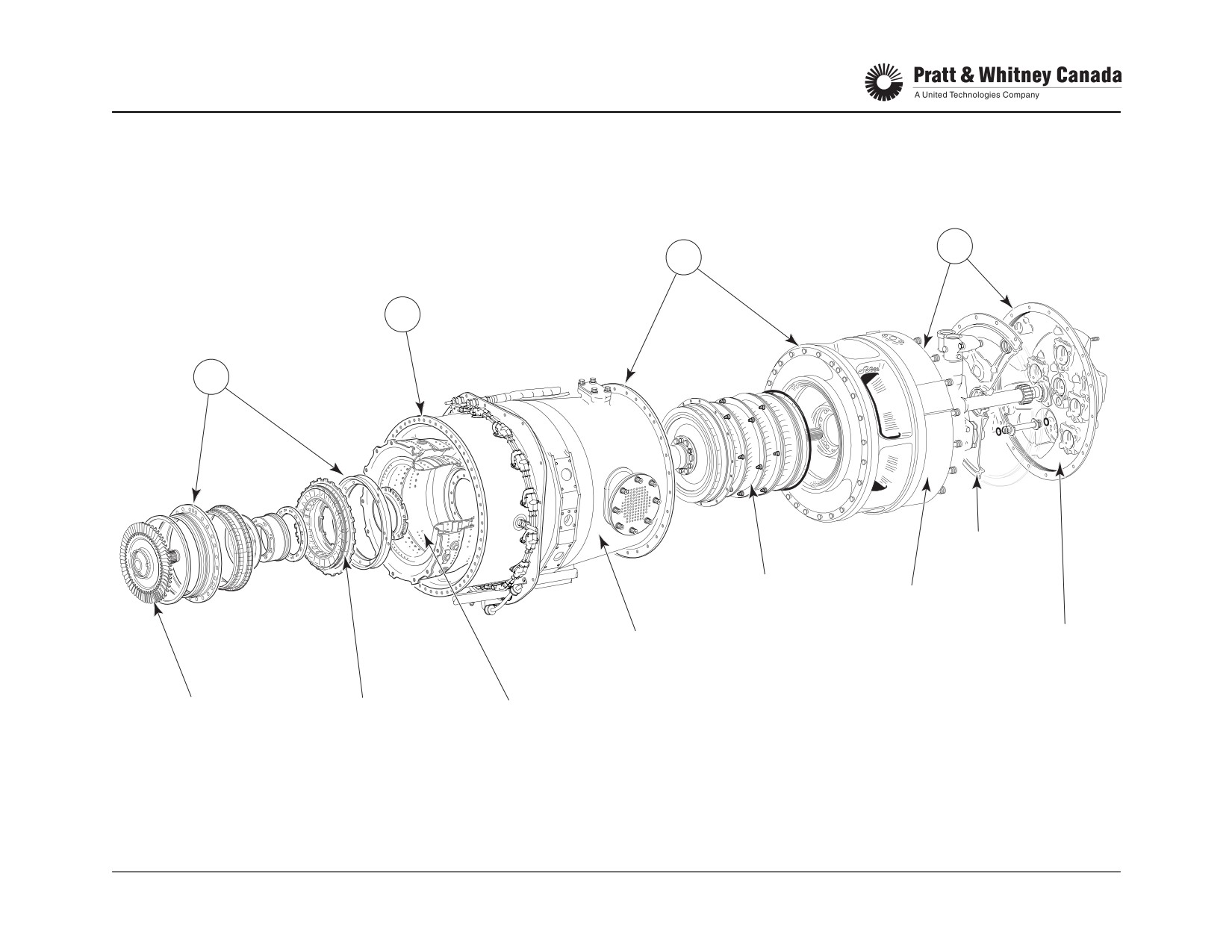
MAJOR ASSEMBLIES & FLANGES
(GAS GENERATOR MODULE)
G
F
C
E
DIAPHRAGM
COMPRESSOR
INLET
ASSEMBLY
CASE
ACCESSORY
GAS GENERATOR
GEARBOX
CASE
COVER
COMPRESSOR
COMPRESSOR
COMBUSTION
TURBINE
TURBINE
CHAMBER
GAS GENERATOR SECTION
VANE RING
PT6A-60 SERIES
TRAINING USE ONLY
ENGINE OVERVIEW 1.7
P&WC Proprietary - Disclosure and use subject to the restrictions on page 2 of preface
FEATURES
Modules:
Reduction Gearbox:
- Gas Generator
- 2 stage planetary reduction
- Power Section
- Built-in hydro-mechanical torque measurement sys-
tem.
Main Components:
- Reduce the power turbine speed to a speed suitable
for propeller operation.
Accessory Gearbox:
- Driven by the compressor
Engine Control System:
- Provide drives for engine and aircraft accessories
- Variable speed propeller
- Reverse thrust capability
Compressor:
- Hydro-pneumatic fuel control unit
- 3 or 4 axial stages plus 1 centrifugal impeller.
- Fuel control with manual override *
- Provides the necessary air mass flow at the required
- Reserve power capability *
pressure to sustain combustion and cool hot section
- Two or Three lever power management *
components.
- Torque limiting device *
Combustion Chamber:
* Applicable to certain models only.
- Annular type
- Reverse flow (shortens engine)
References:
- Provides an area for combustion of the air-fuel mixture
Rated power
700 to 1650 SHP
Max. air mass flow
10.22 to 11.21 lbs./sec
Compressor Turbine:
Max. compressor P/R
9:1 to 12:1
- Single stage (CCW rotation)
Specific fuel consumption
509 to .680 LB/ESHP/hr
- Recuperate power to drive the compressor
Power Turbines:
- 2 stage turbine (CW rotation)
- Independent from the compressor turbine (free tur-
bine)
- Extract energy to turn the propeller
PT6A-60 SERIES
TRAINING USE ONLY
ENGINE OVERVIEW 1.8
P&WC Proprietary - Disclosure and use subject to the restrictions on page 2 of preface
NOTES
PT6A-60 SERIES
TRAINING USE ONLY
ENGINE OVERVIEW 1.9
P&WC Proprietary - Disclosure and use subject to the restrictions on page 2 of preface
GENERAL TURBOPROP OPERATION
The PT6 is a lightweight turbine engine driving a propeller
The hot expanding gases accelerate through the compres-
via a two-stage reduction gearbox. Two major rotating
sor turbine vane ring and cause the compressor turbine to
assemblies compose the heart of the engine. The first is
rotate (which rotates the compressor (approx. 39,000 rpm)).
the compressor and the compressor turbine (compressor
The expanding gases travel across the 1st and 2nd stage
section) and secondly, the two power turbines and the
power turbines which provides rotational energy to drive the
power turbine shaft (power section). The two rotors are not
propeller shaft. The reduction gearbox reduces the power
connected and rotate at different speeds and in opposite
turbine speed (30,000 rpm approx.) to one suitable for pro-
directions. This design is referred to as a "Free Turbine
peller operation (1700/2000 rpm).
Engine” and has certain advantages:
Gases leaving the power turbines are expelled to the atmo-
- Np independent of Ng.
sphere by the exhaust duct.
- Lower Starter cranking torque
- Modular design concept
Engine shutdown is accomplished by shutting off fuel going
- On-wing maintenance (Hot Section Inspection.)
to the combustion chamber.
The compressor draws air into the engine via an annular
An integral oil tank located in the rear section of the inlet
plenum chamber (inlet case), air pressure increases across
case and the accessory gearbox provides oil to bearings
3 or 4 axial stages and one centrifugal stage and is then
and other various systems, such as propeller and torque
directed to the combustion chamber.
systems.
Air enters the combustion chamber via small holes. At the
A Woodward Governor Co. fuel control unit mounted on the
correct compressor speed, fuel is introduced into the com-
accessory gearbox regulates fuel flow to the fuel nozzles in
bustion chamber via 14 fuel nozzles. Two spark igniters
response to power requirements and flight conditions.
located in the combustion chamber ignite the mixture. The
hot gases generated by the combustion are then directed to
The propeller governor mounted on the reduction gearbox,
the turbine area.
controls the speed of the propeller by varying blade angle,
depending on power requirements, pilot speed selection
At this point, ignition is turned off since a continuous flame
and flight conditions.
now exists in the combustion chamber.
PT6A-60 SERIES
TRAINING USE ONLY
ENGINE OVERVIEW 1.10
P&WC Proprietary - Disclosure and use subject to the restrictions on page 2 of preface

TURBOPROP ENGINE
COMPRESSOR
TURBINE
2 ND STAGE
1 ST STAGE
ACCESSORY
POWER
REDUCTION
REDUCTION
GEARBOX
TURBINES
COMPRESSOR
GEAR
GEAR
PROPELLER
SHAFT
PT6A-60 SERIES
TRAINING USE ONLY
ENGINE OVERVIEW 1.11
P&WC Proprietary - Disclosure and use subject to the restrictions on page 2 of preface
MAIN ENGINE BEARINGS
Function:
Operation:
- The ball bearings withstand the following thrusts:
To support major rotating assemblies and minimize friction.
- No. 1 bearing: Compressor thrust (rearward)
- No. 4 bearing: Power turbine thrust (forward)
Ball Bearings:
- No. 6 bearing: Propeller thrust (forward)
- Bearing nos. 2, 3, 5 and 7 are roller bearings
Support axial and radial loads.
- They support radial loading and permit axial rotor
movement caused by thermal expansion
Roller Bearings:
- Bearings are pressure lubricated and cavities are
drained by scavenge pumps
Support radial load only and allows for thermal expansion.
- No. 1 bearing is gravity drained
Rotating Assemblies And Their Supporting Bearings:
Maintenance:
- None at field level
- Inspect oil filter, chip detector
- Keep oil pressure within tolerances
Propeller Shaft
Power Turbine
Compressor
No 5: roller
No 3: roller
No 1: ball
No 6: ball
No 4: ball
No 2: roller
No 7: roller
Note:
Smaller Reduction Gearboxes (PT6A-52/-60/-61/-64 and
-66) do not require a No. 7 bearing.
PT6A-60 SERIES
TRAINING USE ONLY
ENGINE OVERVIEW 1.12
P&WC Proprietary - Disclosure and use subject to the restrictions on page 2 of preface
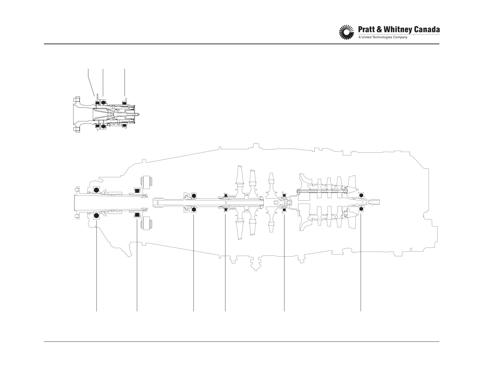
BEARINGS
7
6
5
A-60
A-65
A-67
A-52
A-61
A-64
A-66
6
5
4
3
2
1
PT6A-60 SERIES
TRAINING USE ONLY
ENGINE OVERVIEW 1.13
P&WC Proprietary - Disclosure and use subject to the restrictions on page 2 of preface

STATIONS
7
6
5
4
3
2.5
2
1
1 - AIR INTAKE
2 - COMPRESSOR INLET
2.5 - COMPRESSOR INTERSTAGE
3 - COMPRESSOR DISCHARGE PRESSURE
4 - COMPRESSOR TURBINE INLET
5 - INTERTURBINE
6 - TURBINE EXHAUST
7 - EXHAUST OUTLET
PT6A-60 SERIES
TRAINING USE ONLY
ENGINE OVERVIEW 1.14
P&WC Proprietary - Disclosure and use subject to the restrictions on page 2 of preface
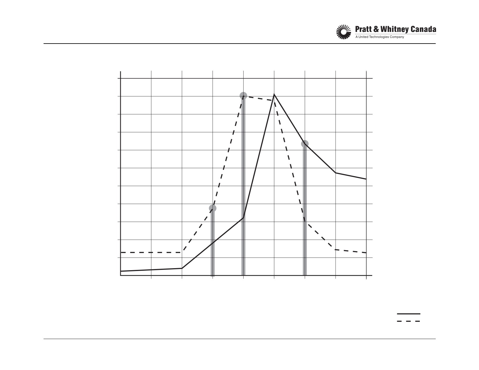
STATIONS
TEMP OC
PRESS
PSIA
1100
1000
150
140
900
130
120
800
110
700
100
600
90
80
500
70
60
400
50
300
40
30
200
20
100
10
0
1
2
P2.5
P3
T4
T5
6
7
NOTE:
PRESSURES AND TEMPERATURES LISTED
ARE TAKEN AT TAKEOFF POWER, STANDARD
TEMPERATURE
DAY FOR A PT6A-65 ENGINE
PRESSURE
PT6A-60 SERIES
TRAINING USE ONLY
ENGINE OVERVIEW 1.15
P&WC Proprietary - Disclosure and use subject to the restrictions on page 2 of preface
ENGINE EXTERNAL COMPONENTS
1.
Reversing Cable
2.
T5 Harness
3.
T1 Trim Resistor (Trim Stick)
4.
Decal Patents Designation
5.
Cam Box (Reversing)
6.
Oil Return From Airframe Cooler
7.
Overboard Breather Discharge
8.
Oil Dipstick - (Electrical A-67B)
9.
Starter/Generator Pad
10.
Fuel Control Unit
11.
Oil To Airframe Cooler
12.
Fuel Pump
13.
Oil To Fuel Heater
14.
Oil Pressure Tapping
15.
P3 Air Filter
16.
Oil Filter Cover
17.
P3 Air Delivery Tube To Fuel Control Unit
18.
Bleed Valve
19.
Main Oil Pressure Line
20.
Propeller Tach-Generator Pad
21.
Data Plate Gas-Generator (Engine)
22.
Plate Instructions, Gas Generator
PT6A-60 SERIES
TRAINING USE ONLY
ENGINE OVERVIEW 1.16
P&WC Proprietary - Disclosure and use subject to the restrictions on page 2 of preface

EXTERNAL COMPONENTS
1
3
2
4
5
6
8
7
9
20
10
19
18
21
17
22
16
11
15
12
14
13
PT6A-60 SERIES
TRAINING USE ONLY
ENGINE OVERVIEW 1.17
P&WC Proprietary - Disclosure and use subject to the restrictions on page 2 of preface
ENGINE EXTERNAL COMPONENTS
1.
Inlet Screen
2.
P2.5 Cabin Bleed
3.
Fireseal - Front
4.
Fuel Nozzle Adapter
5.
Py Air Line
6.
Data Plate - Power Section
7.
Propeller Governor (CSU)
8.
Propeller Shaft
9.
Propeller Overspeed Governor Pad
10.
Torque Oil Pressure Port
11.
Chip Detector
12.
Igniter Plug
13.
Engine Mount Pad
14.
P3 Cabin Bleed Port
15.
Oil Scavenge Tubes
16.
Ignition Cables
17.
Exciter Box
18.
Wash Spray Ring
19.
Oil Level Sightglass
20.
Rear Fireseal
21.
Oil From Airframe Cooler
PT6A-60 SERIES
TRAINING USE ONLY
ENGINE OVERVIEW 1.18
P&WC Proprietary - Disclosure and use subject to the restrictions on page 2 of preface

EXTERNAL COMPONENTS
5
3
2
7
4
1
21
6
8
20
19
18
17
16
14
15
10
9
13
12
11
PT6A-60 SERIES
TRAINING USE ONLY
ENGINE OVERVIEW 1.19
P&WC Proprietary - Disclosure and use subject to the restrictions on page 2 of preface
BLANK PAGE
PT6A-60 SERIES
TRAINING USE ONLY
ENGINE OVERVIEW 1.20
P&WC Proprietary - Disclosure and use subject to the restrictions on page 2 of preface
COMPRESSOR SECTION
COMPRESSOR SECTION
PT6A-60 SERIES
TRAINING USE ONLY
COMPRESSOR SECTION 2.1
P&WC Proprietary - Disclosure and use subject to the restrictions on page 2 of preface
COMPRESSOR SECTION
Function:
Compressor Air Is Used For The Following:
- Supplies the required mass of air at the right pressure
- Sustain combustion in order to produce the energy
to the combustion chamber and all the supporting sys-
required to drive the compressor and the power sec-
tems
tion (propeller)
- Transmits the rotational energy from the compressor
- Provide cooling air for hot section components
turbine to drive the accessories mounted on the acces-
- Provide air to seal bearing cavities
sory gearbox
- Assist in the operation of the fuel control unit
- Controls bleed valve operation
- Provides heating and pressurization for cabin use
Subjects Covered:
- De-ice various airframe components
- Inertial separator (airframe)
- Inlet case
- Compressor assembly
- Bleed valve
- Pre-swirl system (jet flap piccolo inlet)
- Gas generator case
- Cold section cleaning
Operation:
The compressor draws air into the engine and compresses
it before delivery to the combustion chamber area.
PT6A-60 SERIES
TRAINING USE ONLY
COMPRESSOR SECTION 2.2
P&WC Proprietary - Disclosure and use subject to the restrictions on page 2 of preface

COMPRESSOR SECTION
BLEED VALVE
COMPRESSOR
INLET CASE
GAS GENERATOR
PT6A-60 SERIES
TRAINING USE ONLY
COMPRESSOR SECTION 2.3
P&WC Proprietary - Disclosure and use subject to the restrictions on page 2 of preface
INERTIAL SEPARATOR (AIRFRAME)
Function:
Protects the engine from ingesting foreign objects such as
When carrying-out a performance check, always assure
stones, ice, sand, snow, rain, etc.
that the inertial separator doors are in the CLOSED posi-
tion. Inertial separator doors left in the open position will
cause an increase in Ng, ITT and Wf which could be
Operation:
interpreted as a deteriorated compressor.
Deployment of the inertial separator to the bypass (icing)
position forces air in the nacelle to execute a sharp turn
before entering the engine. Water droplets, ice crystals or
snow, because of their inertia, tend to maintain their original
high velocity path and are discharged overboard through
the separator bypass duct.
Note:
The inertial separator is an airframe-supplied item. Not
using the inertial separator in icing conditions could result in
costly damage to the compressor blades. Ensure separator
operates freely. Erratic movement of the separator vane
may cause engine parameter fluctuation. For specific main-
tenance action, refer to the Airframe Maintenance Manual.
PT6A-60 SERIES
TRAINING USE ONLY
COMPRESSOR SECTION 2.4
P&WC Proprietary - Disclosure and use subject to the restrictions on page 2 of preface

INERTIAL SEPARATOR (TYPICAL)
BYPASS (ICING)
POSITION
NORMAL
POSITION
PT6A-60 SERIES
TRAINING USE ONLY
COMPRESSOR SECTION 2.5
P&WC Proprietary - Disclosure and use subject to the restrictions on page 2 of preface
COMPRESSOR INLET CASE
Function:
Maintenance:
- Directs air into the compressor
- Inspect inlet screen for damage and cleanliness. Wire
- Support no. 1 bearing
mesh damage is not acceptable
- Forms the oil tank
- Inspect inlet screen rubber sealing rims for damage
- Piccolo holes in hollow struts generate pre-swirl
- Inspect inlet case for cracks in the strut area
- Sight glass on left side of case allows for quick oil level
- Cracks are not acceptable on Inlet Case
check (not on A-60/61/65)
- Inlet screen (1/4 inch mesh) prevents objects from
entering the compressor
Construction:
- One piece magnesium casting
- External surfaces painted with epoxy paint
Operation:
The annular configuration of the PT6 inlet case facilitates
the protection against Foreign Object Damage (FOD).
Because the compressor rotor intake is not in line with the
flight path, the incoming air makes a sharp turn before
entering the inlet case. This configuration is combined with
the inertial separator for maximum protection against FOD.
Piccolo holes in the inlet case strut change the direction of
incoming air at the face of the compressor rotor. Inlet case
strut anti-icing is provided by heat conduction from the oil
contained in the tank.
PT6A-60 SERIES
TRAINING USE ONLY
COMPRESSOR SECTION 2.6
P&WC Proprietary - Disclosure and use subject to the restrictions on page 2 of preface
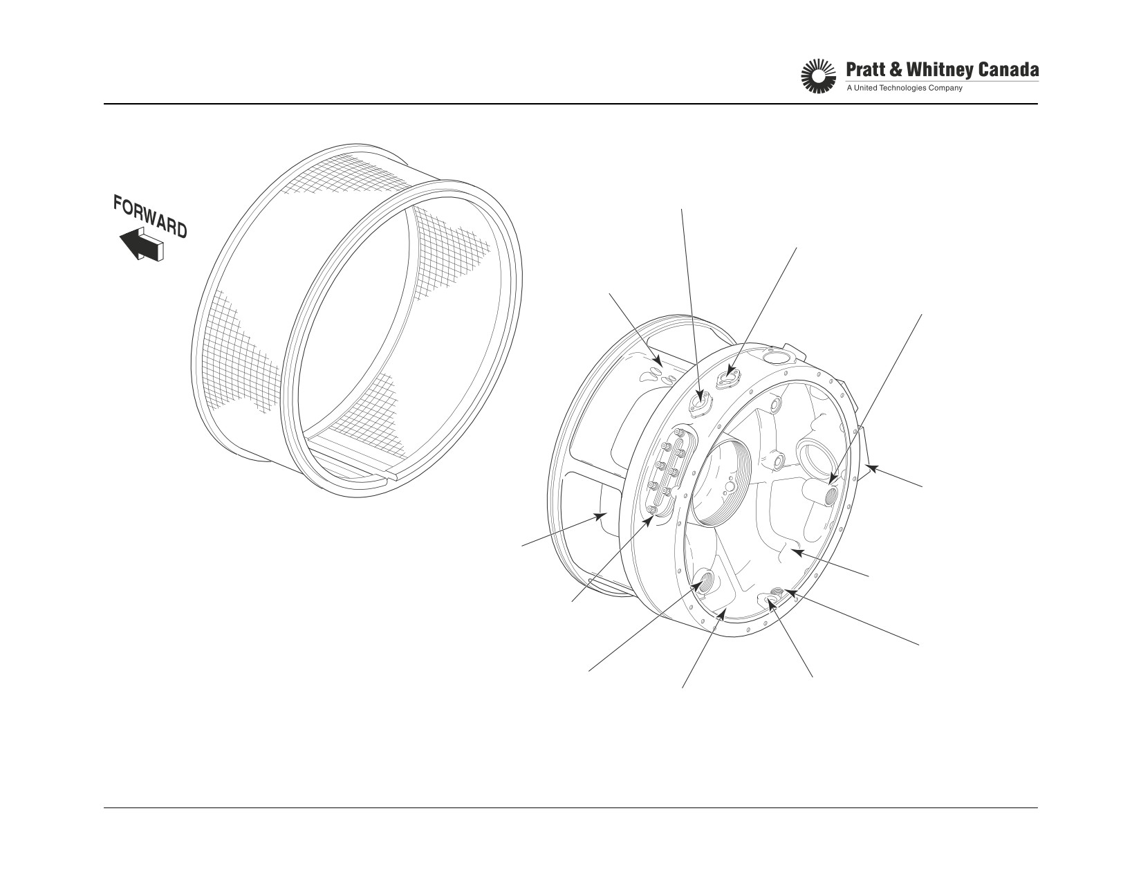
INLET CASE
OIL TANK VENT
AND PRESSURIZING
VALVE
OIL RETURN FROM COOLER
PICOLLO
HOLES
OIL TO AGB
OIL FILTER
HOUSING
INLET SCREEN
LOCATION
AIR INLET
OIL FROM
THERMOSTATIC
AND BYPASS VALVE
OIL LEVEL SIGHT GLASS
OIL TANK
NO.1 BEARING
DRAIN
SCAVENGE
NO.2 BEARING
OIL TANK
SCAVENGE
RETURN
PT6A-60 SERIES
TRAINING USE ONLY
COMPRESSOR SECTION 2.7
P&WC Proprietary - Disclosure and use subject to the restrictions on page 2 of preface
COMPRESSOR
Function:
Compression Ratios:
- Provides the combustion chamber with the correct air-
flow at the required pressure
52, 60A,61
9.0
- The number 1 bearing supports the rear end of the
compressor
64, 65, 66, 67
12.1
- The flexible housing transforms compressor vibrations
Operation:
Construction:
Axial stage accelerates the air, which is then decelerated
A-52/60/61:
through divergent stator vanes, thus increasing the air pres-
- Three axial rotors and a centrifugal impeller
sure. The same process is repeated throughout all the com-
- Early engines used assembly of disks and blades for
pressor stages.
all 3 axial stages
The dynamic pressure (air velocity) generated by the cen-
- SB 13093, introduces integral bladed rotor (IBR) on
trifugal impeller speed is transformed into static pressure by
1st. stage only
the diffuser pipes divergent shape which reduces the air
speed and increases the compressor discharge pressure
A-65’s:
(P3).
- Four axial (blade & hub) rotors and a centrifugal impel-
Nos. 1 and 2 bearings support the compressor rotor. The
ler.
IBR root forms the inner gas path profile; the stator vanes
- SB 13017 Introduces 1st stage IBR.
form the outer gas path wall.
- SB 13140 Introduces 4 stages of IBR’s.
The no. 1 bearing is supported by the compressor inlet
case via a flexible housing. Compressor unbalance caused
A-64. 66 & 67:
by normal engine wear produces vibrations that are trans-
- Four IBR type axial rotors and a centrifugal impeller
formed by the number 1 bearing flexible housing, reducing
vibrations transmitted to the engine mounts and aircraft.
Stator vanes are mounted after each axial rotor. Rotating
components are made of titanium and are held in place with
Maintenance:
tie rods that extend through the compressor stages.
- Check first stage blades for FOD every time the inlet
Maximum compressor speed 39,000 rpm (104%).
screen is removed
- Blending is recommended to prevent cracks from
developing on the leading edge of the blades
- Refer to the Engine Maintenance Manual for accept-
able blade damage and blending limits
- Do compressor Wash at regular intervals
PT6A-60 SERIES
TRAINING USE ONLY
COMPRESSOR SECTION 2.8
P&WC Proprietary - Disclosure and use subject to the restrictions on page 2 of preface

COMPRESSOR
BLEED
AXIAL
VALVE
STAGES
NO. 2 BRG.
PICCOLO
CENTRIFUGAL
HOLES
IMPELLER
NO. 1 BRG.
NO. 1 BRG.
FLEXIBLE
HOUSING
GAS
GENERATOR
INLET CASE
CASE
PT6A-60 SERIES
TRAINING USE ONLY
COMPRESSOR SECTION 2.9
P&WC Proprietary - Disclosure and use subject to the restrictions on page 2 of preface
COMPRESSOR WASH
Function:
- Remove salt and dirt deposits from the compressor
After Wash Procedure:
gas path
- Reconnect P3 line to the FCU
- Promote parts life and reduce potential overhaul costs
Special Procedure:
- If isopropyl alcohol or kerosene was used in the
Type Of Washes:
cleaning solution perform a dry motoring run before
- Desalination wash
starting the engine to avoid a hot start.
- Performance recovery wash
- Ref. M/M 71-00-00
Desalination Wash:
- Recommended when operating in a salt laden atmo-
sphere
Method:
- Use drinking water with low mineral content
- Motoring wash
- De-mineralized water is recommended
- Refer to the Engine Maintenance Manual for washing
mixtures preparation and procedures
Performance Recovery Wash:
- Recommended every 100 - 200 hr based on the flying
environment
Prior To Washing, Make Sure That:
- Water based detergents are used to remove stubborn
- 40 minutes minimum cooling period
dirt deposits which cannot be removed using water
- P3 line going to the FCU is removed*
only
- Cabin bleed is off
- Solution is injected into the compressor using the
- No power extraction
wash ring mounted over the inlet screen
- Follow starter limitations
- At OAT below 2 °C (36 °F), isopropyl alcohol must be
- Ensure removal of exhaust duct drain plug if installed
added to the water to prevent freezing
* Not applicable if post SB 13175/14054 (P3 filter bowl drain valve)
- Allow 15-20 minute soaking period
- Perform two rinse cycles (water)
PT6A-60 SERIES
TRAINING USE ONLY
COMPRESSOR SECTION 2.10
P&WC Proprietary - Disclosure and use subject to the restrictions on page 2 of preface

COMPRESSOR WASH
COMPRESSOR
WASH RING
SHUTOFF
CLEANING
SHUTOFF
VALVE
SOLUTION
VALVE
PRESS.
PRESS.
GAGE
GAGE
REGULATED
SPRAY
SPRAY
AIR PRESSURE
RING
RING
WATER
REGULATED
AIR PRESSURE
WATER
DESALINATION SYSTEM
PERFORMANCE RECOVERY SYSTEM
PT6A-60 SERIES
TRAINING USE ONLY
COMPRESSOR SECTION 2.11
P&WC Proprietary - Disclosure and use subject to the restrictions on page 2 of preface
COMPRESSOR BLEED VALVE (64/65/66/67)
Function:
Px pressure depends on the restriction at the outlet of the
cavity where it is drawn. This restriction is controlled by the
Prevents compressor stall at low Ng.
inside diameter of the compressor turbine stator air seal
(baffle). SB14117 introduces a classified stator air seal on
Construction:
certain engine models to improve control of Px pressure.
- Non-flowing type
Some late A-65 models also incorporate a classified stator
- A piston slides on a guide pin inside a housing
air seal. ( SB 13108 & SB 13311 )
- Seal rings on the piston minimize Px leak
- A classified seat controls the closing point (Ng) of the
The surface area on which P2.5 pushes depends on the
bleed valve
inside diameter of the bleed valve classified seat. Different
classes of seats are available for bleed valve closing point
Operation:
adjustment.
Two forces act on the bleed valve piston. Px air pressure
pushes to close the bleed valve and P2.5 air pressure, from
Maintenance:
the inter-stage compressor area, pushes to open it. Px is
- Check for evidence of air losses at sealing faces and
derived from P3 air. P3 passes through a restriction when it
mating surface
flows between the no. 2 bearing housing and the no. 2 bear-
- Check valve seat/piston for damage
ing cover. At low power setting, Px is lower than P2.5 keep-
- Check free movement of piston
ing the bleed valve open. In this position, P2.5 air is directed
- Bleed valve closing point
into the plenum chamber and into the inlet case struts.
- Retain classified seat when replacing bleed valve
When the compressor speed increases, Px rises faster than
P2.5, thus increasing the pressure acting on top of the pis-
The piston can fall out of the BOV assembly
ton to gradually close it. The speed (Ng) at which the valve
when the classified seat is removed
closes is a function of 2 variables. One is the Px pressure
and the second is the surface area on which P2.5 air pres-
sure is pushing on the piston.
PT6A-60 SERIES
TRAINING USE ONLY
COMPRESSOR SECTION 2.12
P&WC Proprietary - Disclosure and use subject to the restrictions on page 2 of preface

COMPRESSOR BLEED VALVE (64/65/66/67)
SEAL RING
RETAINING
RING
DETAIL A
BLEED VALVE
GUIDE PIN
COVER
A
PX
PX
PISTON
BLEED
SEAL RING
VALVE
VALVE SEAT
HOUSING
CLASSIFIED
RETAINING RING
VALVE SEAT
SEAL RING
PX (P3)
PISTON
P2.5
PT6A-60 SERIES
TRAINING USE ONLY
COMPRESSOR SECTION 2.13
P&WC Proprietary - Disclosure and use subject to the restrictions on page 2 of preface
COMPRESSOR BLEED VALVE (52/60/61)
Function:
As Ng increases, P3 rises faster than P2.5, thus increasing
the pressure acting on the piston to gradually close it. The
Prevents compressor stall at low Ng
speed (Ng) at which the valve closes is a function of the Pri-
mary and Convergent Divergent orifice sizes. A larger Pri-
Description:
mary orifice requires less Ng speed (less P3 pressure) to
close the valve.
Pressure operated piston sliding on a guide pin. Piston dis-
charges P2.5 to atmosphere at low Ng. speed. A rolling
Maintenance:
diaphragm mounted on the valve piston prevents leakage
- Check for air losses at sealing faces and mating sur-
between P2.5 and the Px chamber.
faces
- Check that piston moves freely
Construction:
- Check seat or piston for damage
- Flowing type
- Pressure check
- A piston slides on a guide pin inside a housing
- Clean orifices
- A flexible diaphragm seals the piston
- Calibrated orifices control the valve closing point (Ng)
Pressure Check:
Operation:
To verify the integrity of the Bleed Valve diaphragm
Two forces act on the bleed valve piston. Modified P3 air
Description:
(Px) pressure pushes to close the valve and P2.5 air pres-
- Remove Bleed valve spring pin
sure, from the inter-stage compressor area, pushes to open
- Seal valve seat on a rubber sheet and secure in posi-
it.
tion
- Remove two plugs on Bleed valves and install appro-
P3 air flows through a primary metering orifice and is
priate equipment as per M/M
directed to the top of the piston and to atmosphere via a
- Apply required pressure to valve and check that leak-
convergent divergent orifice. The bleed valve closing point
age is within limits
occurs, during engine acceleration, when the pressure act-
ing on the valve diaphragm (Px) is sufficient to overcome
the compressor inter-stage pressure (P2.5).
PT6A-60 SERIES
TRAINING USE ONLY
COMPRESSOR SECTION 2.14
P&WC Proprietary - Disclosure and use subject to the restrictions on page 2 of preface

BLEED VALVE (52/60/61)
CONTROL PRESSURE (Px)
AMBIENT PRESSURE (Pa)
COVER
FINAL
ROLLING DIAPHRAGM
ORIFICE
GUIDE PIN SHAFT
PISTON
Px
Px
PRIMARY
ORIFICE
DISCHARGE
PISTON DAMPER
TO ATMOSPHERE
DELIVERY
(SPRING LOADED)
AIR
PASSAGE
P3
P3
PISTON SEAT
SLEEVE
P2.5
P2.5
CLOSED POSITION
OPEN POSITION
PT6A-60 SERIES
TRAINING USE ONLY
COMPRESSOR SECTION 2.15
P&WC Proprietary - Disclosure and use subject to the restrictions on page 2 of preface
PRE-SWIRL SYSTEM
Function:
Operation:
- Change the relative angle of attack of the air entering
the compressor
When the bleed valve opens, P2.5 air flows to the plenum
- Improve surge margin at low compressor speed
chamber and to the inlet case hollow struts. The piccolo
holes located on the inlet case struts produce P2.5 air jets
Description:
that cause swirling of the incoming air before it enters the
-
Hollow inlet case struts with holes
compressor. The swirl is turning in the same direction of
-
Piccolo holes on most A-64/67
the compressor, which makes it easier to draw in air thus
-
Slotted holes combined with swing check valve and
increase compressor performance at low Ng.
orifice A-52/60/61, A65AG,AR
-
Bleed valve
Swing Check Valve:
-
Bleed valve plenum chamber
Pre-SB13016 A-65 engines use an orifice and a swing
check valve to relieve excess P2.5 air pressure when the
compressor bleed valve opens. The swing check valve is on
the left-hand side of the gas generator on A-65's, or on top
of the bleed valve for A-52/60/61's. The swing check valve
prevents air from entering the plenum chamber at high
power after the bleed valve has closed. Inlet case with Pic-
colo holes can handle all the airflow without a swing check
valve.
Maintenance:
- Check for proper operation of the bleed valve
- Proper installation/sealing of the bleed valve
PT6A-60 SERIES
TRAINING USE ONLY
COMPRESSOR SECTION 2.16
P&WC Proprietary - Disclosure and use subject to the restrictions on page 2 of preface
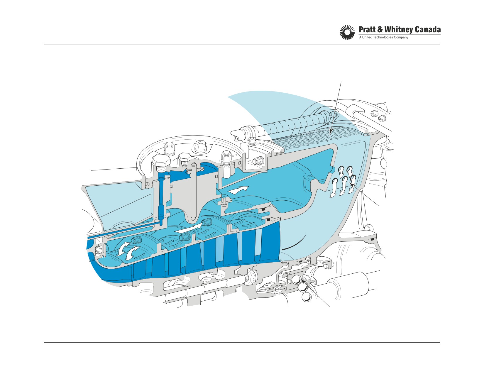
PRE-SWIRL SYSTEM (PICCOLO HOLES)
INLET SCREEN
INLET AIR
P 2.5
INTERSTAGE
AIR
PICCOLO
HOLES
NO. 1 BEARING
PT6A-60 SERIES
TRAINING USE ONLY
COMPRESSOR SECTION 2.17
P&WC Proprietary - Disclosure and use subject to the restrictions on page 2 of preface
NOTES
PT6A-60 SERIES
TRAINING USE ONLY
COMPRESSOR SECTION 2.18
P&WC Proprietary - Disclosure and use subject to the restrictions on page 2 of preface
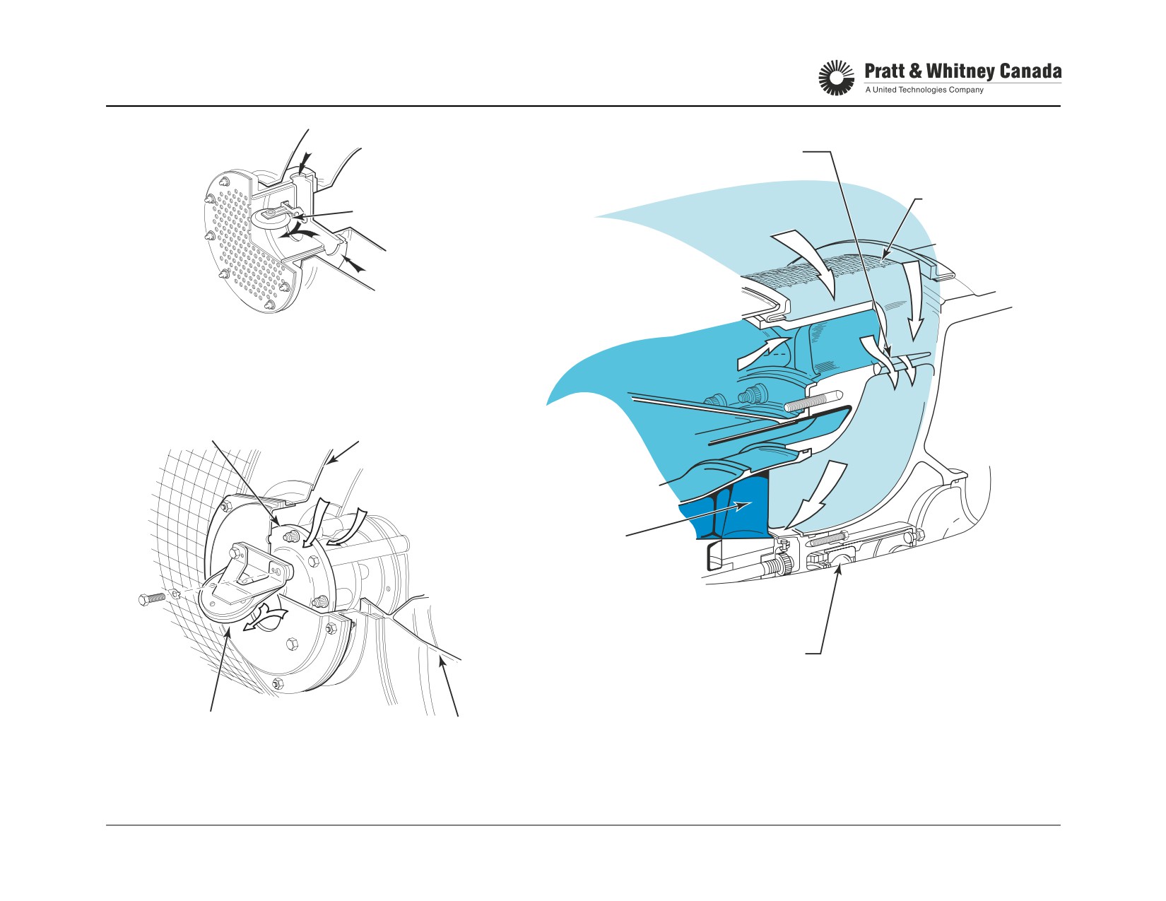
PRE-SWIRL SYSTEM (52/60/61) (SLOTTED STRUTS)
CASE HOLLOW STRUT
TANGENTIAL FLOW (JET FLAP)
SWING
INLET SCREEN
CHECK VALVE
AIR INLET
A65’s
P 2.5 INTER-STAGE AIR
COMPRESSOR
BLEED VALVE
BLEED AIR CASE
ASSEMBLY
P 2.5
P 2.5
FIRST - STAGE
COMPRESSOR BLADE
P 2.5
NO. 1 BRG. (REF)
GAS
SWING CHECK
GENERATOR
VALVE
CASE
A52/60/61
PT6A-60 SERIES
TRAINING USE ONLY
COMPRESSOR SECTION 2.19
P&WC Proprietary - Disclosure and use subject to the restrictions on page 2 of preface
BLEED VALVE CLOSING POINT (65/67)
Function:
Note:
If closing point does not fall within the tolerance band, the
To verify at what Ng speed the bleed valve closes.
following adjustments can be made.
- Install higher class seat to raise Ng closing point
Description:
- Install lower class seat to lower Ng closing point
- Replace bleed valve if piston does not move freely
Use the pressure pick-up port located on the P2.5 cabin
bleed adapter.
Bleed Valve Closing Point (64/66):
Operation:
There is no closing point test for these models.
- The pick-up tube connects to a flexible hose in a con-
tainer filled with water
- Bubbles form when the bleed valve opens
- Stabilize engine at ground idle
- Increase Ng until bubbles stop forming
- Record Ng speed (closing point)
- Ensure closing point falls within tolerance band on MM
graph
PT6A-60 SERIES
TRAINING USE ONLY
COMPRESSOR SECTION 2.20
P&WC Proprietary - Disclosure and use subject to the restrictions on page 2 of preface

BLEED VALVE CLOSING POINT CHECK
37.5
96
95.1
94
NOTE:
OPERATING ABOVE
THE BAND
IS ACCEPTABLE.
92
90
RUBBER
88
TUBE
86
85.55
NOTE:
OPERATING BELOW THE BAND
IS NOT RECOMMENDED, AS THIS
84.25
MAY RESULT IN ENGINE STALL / SURGE
84
DURING ACCELERATION / DECELERATION.
82
−30
−20
−10
0
10
20
30
40
OUTSIDE AIR TEoPERATURE ( C)
BUBBLERWATER
PT6A-60 SERIES
TRAINING USE ONLY
COMPRESSOR SECTION 2.21
P&WC Proprietary - Disclosure and use subject to the restrictions on page 2 of preface
BLEED VALVE CLOSING POINT (52/60A/61)
Description:
Closing Point Too HIGH (Ng) ->Install Larger Orifice:
A different closing point test is required for these BOV’s
because these engines are ‘flat rated’ so they can make
If plotted point is above acceptable range with
more power at higher altitudes and temperatures. For this
existing class of metering plug, and falls
reason the BOV is open under most circumstances at low
below acceptable range with next higher class
altitude and temperature (on the ground).
from existing plug, the Final Orifice
(convergent/divergent) must be enlarged.
The closing point is extrapolated in reference to a running
Refer to M/M section 71-00-00 Adjustment/
condition taken as follows:
Test
-
Remove P2.5 transfer tube from bleed air case and
install adapter using suitable flexible tube. Connect to
a digital pressure gauge.
-
Record Tam in degree °C, and Pam in In. Hg.
-
Start engine, let Ng stabilize at ground idle.
-
Slowly increase power until plenum pressure (PP)
peaks, then starts falling.
-
Continue to accelerate engine to max. allowable power
Ref. M/M. 71-00-00.
-
Let engine stabilize for 2 minutes, record Ng and PP
-
Shut down engine.
-
Calculate normalized Gas Generator speed and nor-
malized plenum pressure as per M/M. 71-00-00
(Adjustment/Test) to determine the closing point as
per the chart in the MM.
-
If closing point is above or below acceptable range
replace the primary metering plug with next higher or
lower class as required.
PT6A-60 SERIES
TRAINING USE ONLY
COMPRESSOR SECTION 2.22
P&WC Proprietary - Disclosure and use subject to the restrictions on page 2 of preface

BLEED VALVE CLOSING POINT CHECK (52/60/61)
CABIN BLEED AIR
TRANSFER TUBE BOSS
DIGITAL
PRESSURE
GAGE
PT6A-60 SERIES
TRAINING USE ONLY
COMPRESSOR SECTION 2.23
P&WC Proprietary - Disclosure and use subject to the restrictions on page 2 of preface
GAS GENERATOR CASE
Function:
Operation:
Houses and supports various engine components such as
The gas generator case houses the components necessary
#2 brg, compressor assembly, engine mounts, diffuser
for the compression of air and combustion of the fuel/air
pipes.
mixture. The gas generator case contains P3 air pressure.
The diffuser pipes change the high velocity (2000ft/sec) low
Tubes for oil pressure and scavenge to the number 2 bear-
pressure into low velocity (200ft/sec) and high pressure.
ing as well as tapping for P3 air for the operation of the
They also turn the air flow 90° to direct the air to the Com-
bleed valve and fuel control unit are provided inside the gas
bustion Chamber.
generator case.
Description:
Two P3 operated drain valves located at the six o'clock posi-
- Welded assembly of steel alloy machined parts and
tion ensures fuel does not remain in the case after engine
sheet metal
shutdown.
- Diffused aluminized coating
- 21 brazed diffuser pipes
Maintenance:
- Support for the compressor stator parts
- Inspect for cracks and signs of P3 leaks.
- Support for the no. 2 bearing
- Inspect engine mount threaded holes.
- 14 bosses for fuel nozzles
- Inspect diffuser pipes for cracks etc.
- 2 bosses for igniter plugs
- 2 bosses for drain valves
Note:
- 1 boss for P3 air (to FCU)
The A67B & D models have studs instead of bolts to secure
- 1 P2.5 bleed port
the nozzles
- 2 P3 bleed port (A-60/61/65 one)
- Provision for 6 engine mounts (A-60/61/65 four)
PT6A-60 SERIES
TRAINING USE ONLY
COMPRESSOR SECTION 2.24
P&WC Proprietary - Disclosure and use subject to the restrictions on page 2 of preface

GAS GENERATOR CASE / DIFFUSER
AIR PRESSURE TUBE
DIFFUSER PIPE
TO BLEED VALVE
FLANGE "C"
NO. 2 BEARING.
PRESSURE OIL TUBE
P3 PRESSURE TUBE
NO. 2 BEARING
TO FUEL CONTROL
SCAVENGE OIL TUBE
STRAIGHTENING VANE
PT6A-60 SERIES
TRAINING USE ONLY
COMPRESSOR SECTION 2.25
P&WC Proprietary - Disclosure and use subject to the restrictions on page 2 of preface
COLD SECTION TROUBLESHOOTING
Problem
Symptoms At Constant Power
Action Required
Ng
T5
Wf
Restricted inlet screen
up
up
up
Clean and/or remove obstruction
Dirty compressor
up
up
up
Perform compressor wash /revise
schedule
Damaged compressor blades
up
up
up
Blend blades as per Engine
Maintenance Manual. Return to
an approved overhaul facility if
damage is beyond limit.
Bleed valve stuck open or clos-
up
up
up
Ensure P3 is not leaking between
ing at too high Ng
bleed valve and gas generator
case. Replace bleed valve.
P3 leaks
same
up
up
Check for external leaks on gas
generator. Verify sealing surfaces
in Hot section at next HSI. Check
engine bleed system.
Excessive loading of starter gen-
down
up
up
Replace faulty starter
erator or other AGB mounted
accessories.
Bleed valve closes too soon
Compressor stalls during acceleration at altitude
Replace faulty BOV. Re-check
closing point.
Bleed valve stuck closed
Compressor stalls
Replace bleed valve
Note:
Generally, compressor section problems cause Ng, T5 and Wf to increase. However, the above list of possible problems
includes some that will make the engine react differently.
PT6A-60 SERIES
TRAINING USE ONLY
COMPRESSOR SECTION 2.26
P&WC Proprietary - Disclosure and use subject to the restrictions on page 2 of preface
COMBUSTION & TURBINE
COMBUSTION & TURBINE
PT6A-60 SERIES
TRAINING USE ONLY
COMBUSTION & TURBINE 3.1
P&WC Proprietary - Disclosure and use subject to the restrictions on page 2 of preface
HOT SECTION
Description:
Produce and extract energy from the hot expanding gases
to drive the compressor turbine, compressor and AGB
accessories. At the same time, drive the power turbines /
propeller to provide thrust for the aircraft.
Components:
- Combustion chamber
- Compressor turbine vane ring
- Compressor turbine
- Power turbine housing
- Power turbine vane rings
- Power turbines
- Exhaust duct
Operation:
The hot section of the engine is comprised of components
down stream of the compressor. Hot expanding gases
leaving the combustion chamber are directed towards the
compressor turbine blades by the compressor turbine vane
ring and drive the compressor. Gases then travel across
the 1st stage power turbine vane ring and drive the 1st stage
power turbine (and again across the 2nd stages).
Turbine rotation is transmitted to the propeller via the power
turbine shaft and the reduction gearbox. Gases leaving the
power turbine are expelled to the atmosphere through the
exhaust duct. The exhaust gases add some ‘jet thrust’ as a
result of the airframe exhaust stubs.
PT6A-60 SERIES
TRAINING USE ONLY
COMBUSTION & TURBINE 3.2
P&WC Proprietary - Disclosure and use subject to the restrictions on page 2 of preface

HOT SECTION AREA
POWER TURBINE
POWER
POWER
STATOR HOUSING
EXHAUST
TURBINES
TURBINE
CASE
VANE RINGS
NO. 2 BRG
COMBUSTION
COVER
CHAMBER
COMPRESSOR
FLANGE
TURBINE
VANE RING
SHROUD
LOCK
SEALING
SHROUD
SEGMENTS
PLATE
RING
SEGMENT
COMPRESSOR
HOUSING
TURBINE
SMALL EXIT
NO. 2 BRG
C.T. BAFFLE
DUCT
COVER
PT6A-60 SERIES
TRAINING USE ONLY
COMBUSTION & TURBINE 3.3
P&WC Proprietary - Disclosure and use subject to the restrictions on page 2 of preface
COMBUSTION CHAMBER LINER & SMALL EXIT DUCT
Function:
The combustion chamber forms an envelope that turns the
gas 180°. This configuration permits location of the tur-
Provide an area for the combustion of fuel/air mixture and
bines closer to the compressor and within the combustion
form an envelope that changes the direction of the gas flow
chamber area, thus making the engine shorter and lighter.
180°.
Cooling rings direct P3 air into the combustion chamber,
close to the walls, to form a flame barrier.
Construction:
Maintenance:
- Annular, reverse flow type combustion chamber
- Replace the liners as a set.
- Made of nickel alloy (Inconel) sheet metal
- Check the cooling ring gaps as per MM.
- Ceramic coating on inner walls create a thermal bar-
- Inspect for cracks, burning, buckling repair as per MM.
rier
- 14 fuel nozzle bosses
- 2 spark igniter bosses
Troubleshooting:
- Cooling rings protect the combustion chamber walls
from the flame
Intermittent puffs of black smoke indicate carbon build-up in
the C.C. The fix is to incorporate a liner with more cooling
holes (SB13177/14055) or replace the existing liners with a
Operation:
TDF* liner (SB 14048).
P3 air enters the combustion chamber through holes in the
* Thermal Distribution Factor
inner and outer liners. The shape, size and location of
these holes provide the correct fuel/air ratio for all operating
conditions.
PT6A-60 SERIES
TRAINING USE ONLY
COMBUSTION & TURBINE 3.4
P&WC Proprietary - Disclosure and use subject to the restrictions on page 2 of preface

COMBUSTION CHAMBER AND SMALL EXIT DUCT
FUEL NOZZLE
COOLING RINGS
ADAPTER BOSSES
LOUVERED COOLING RING
OUTER LINER
OUTER LINER
INNER LINER
SMALL
INNER LINER
SPARK
EXIT
IGNITER BOSS
DUCT
SMALL EXIT DUCT
COOLING RING
PT6A-60 SERIES
TRAINING USE ONLY
COMBUSTION & TURBINE 3.5
P&WC Proprietary - Disclosure and use subject to the restrictions on page 2 of preface
COMPRESSOR TURBINE VANE RING
Vane Ring:
Operation:
- Directs and accelerates gases to the compressor tur-
bine at the optimum angle and speed.
The compressor turbine vane ring receives hot gases from
- Convergent vanes change static pressure into velocity
the combustion chamber. The vane airfoil arrangement
- The lug to slot fit determines the radial location of the
converges the air towards the exit, accelerating and chang-
shroud housing and is important for tip clearance con-
ing its direction simultaneously.
trol
Vane ring classes determine the sum of the area in square
Effect Of Vane Area (Class) On T5 And Ng At Constant
inches, of all the openings between the vane trailing edges.
Power:
At assembly, the proper class of vane is selected to ensure
that NG and T5 will be within specified limits. A lower vane
ring class (smaller area) accelerates the air therefore
increases the speed of the compressor turbine and com-
Increase Area
Ng ↓
T5 ↑
pressor (Ng). A higher Ng speed provides more air to the
Decrease Area
Ng ↑
T5 ↓
engine, increasing cooling and lowering T5.
Shroud Housing:
The compressor turbine vane ring is subject to very high
- Supports shroud segments and inter-stage sealing
temperatures. Vane airfoils are cooled with P3 air. After
ring
cooling, air is ejected in the gas path at the vane trailing
- Slots in the shroud housing match with corresponding
edge.
lugs on the vane ring to prevent shroud housing rota-
tion
Shroud segments come in different classes (thickness) to fit
different compressor turbine diameters this maintains the
Shroud Segments:
gap between the compressor turbine blades and the seg-
- Correct class selection and grinding of shroud seg-
ments (tip clearance) within specified limits.
ments provide adequate blade tip clearance and mini-
mize gas leakage. (10 or 20 segments)
Replacement:
- Thickness is classified to fit different compressor tur-
bine outside diameter
Replace with same area as original or within ±0.03 sq.in.
of the original class from the last test. (Ref. SIL PT6A-032)
PT6A-60 SERIES
TRAINING USE ONLY
COMBUSTION & TURBINE 3.6
P&WC Proprietary - Disclosure and use subject to the restrictions on page 2 of preface

COMPRESSOR TURBINE VANE RING (52/60/61)
COMPRESSIBLE
SEALS
INTERSTAGE
(SB13168)
SEAL RINGS
SMALL
P3 AIR
EXIT DUCT
OUTER
VANE
TIP
LINER
RING
CLEARANCE
SHROUD
HOUSING
P3 AIR
P3
LOCK
PLATE
SHROUD
P3
SEGMENT
NO.2 BEARING
P3
COVER
COMPRESSOR
TURBINE
POST-SB 13181
PRE-SB 13181
PT6A-60 SERIES
TRAINING USE ONLY
COMBUSTION & TURBINE 3.7
P&WC Proprietary - Disclosure and use subject to the restrictions on page 2 of preface
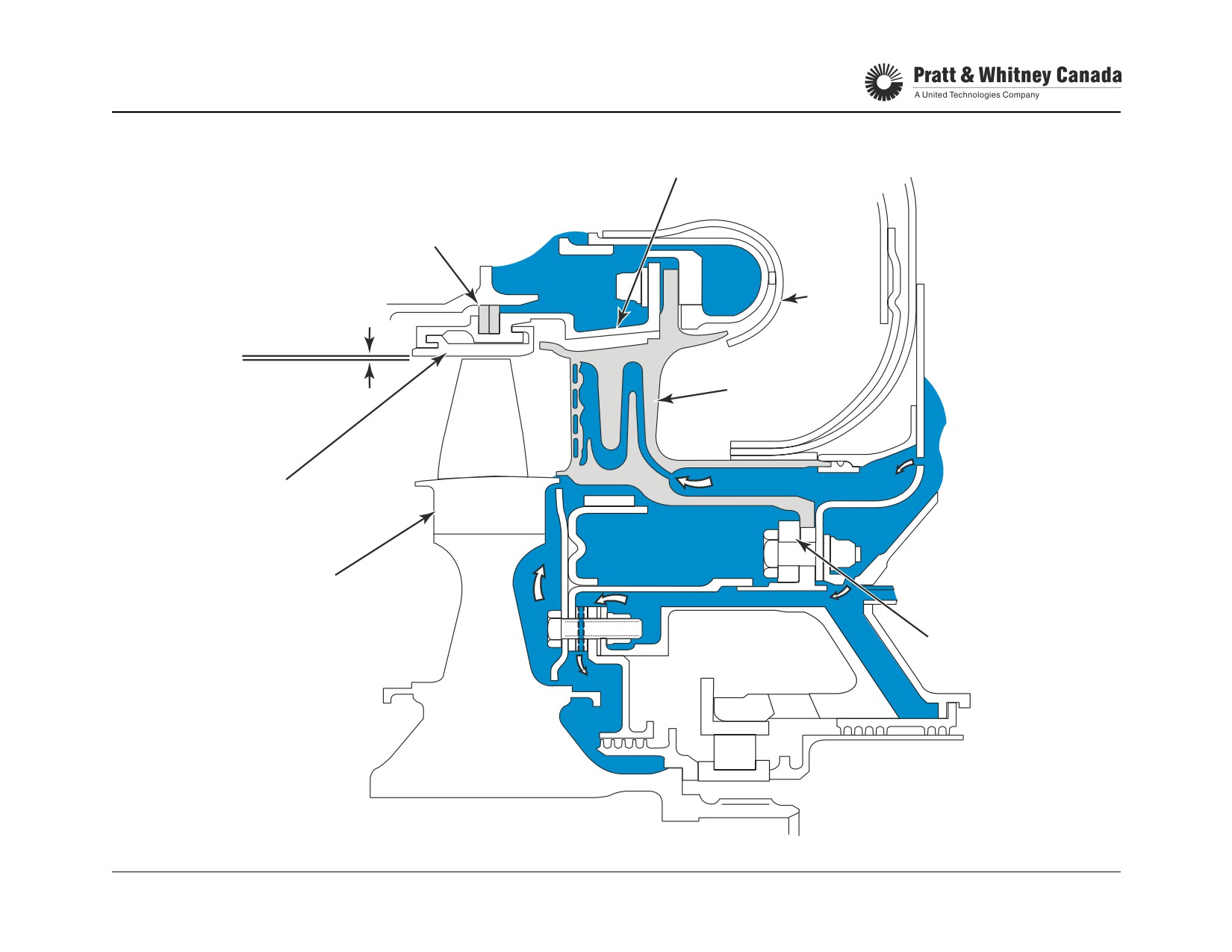
COMPRESSOR TURBINE VANE RING
(64, 66, 67A, AG, AF, R)
SHROUD HOUSING
INTERSTAGE
SEALING RINGS
SMALL
P3 AIR
EXIT
TIP
DUCT
CLEARANCE
VANE
RING
P3 AIR
SHROUD
SEGMENTS
P3
COMPRESSOR
P3
TURBINE
LOCK
PLATE
PT6A-60 SERIES
TRAINING USE ONLY
COMBUSTION & TURBINE 3.8
P&WC Proprietary - Disclosure and use subject to the restrictions on page 2 of preface

COMPRESSOR TURBINE VANE RING
(66B, 66D, 67B, 67D, 67F and 67P)
COMPRESSIBLE
SEALS
INTERSTAGE
SMALL
P3 AIR
SEALING RINGS
EXIT
DUCT
TIP
P3 AIR
CLEARANCE
VANE
RING
SEAL RING
P3 AIR
P3 AIR
COMPRESSOR
TURBINE
P3 AIR
LOCK PLATE
NO.2 BEARING COVER
PT6A-60 SERIES
TRAINING USE ONLY
COMBUSTION & TURBINE 3.9
P&WC Proprietary - Disclosure and use subject to the restrictions on page 2 of preface
COMPRESSOR TURBINE
Function:
At maximum speed, the compressor rotor turns at approxi-
mately 39,000 rpm (104%), with each blade pulling on the
Extract energy from the hot gases to turn the compressor
disk with a force of approximately one ton (2000 lbs.).
rotor unit.
The turbine is individually balanced on two planes with
detail weights. This feature allows for turbine replacement in
Description:
the field. The PT6A-64/66/67 has detail weights plus trim
- Turbine disk is machined from a nickel alloy.
weights to match the disk to the compressor rotor.
- Blades are cast of a nickel-based alloy and coated with
a sacrificial coating for protection against sulphidation.
- Fir-tree serration’s support turbine blades and allow for
thermal expansion differences between the blades
Engine Type
# Of Blades
and the disk
- Rivets lock the blades onto the disk
A52/60/61/65
59
- A master spline on the disk ensures reinstallation of
A64 pre SB14118
52
the compressor turbine in its initial position
A66/67R,A,AF pre SB14061
- PT6A-64/67 blade tip is hollow (pocketed), to reduce
weight and centrifugal pull
A64 post SB14118
43
A66/67R,A,AF post SB 14061
A66B/D, A67B, D, F, P
Operation:
Expanding gases, accelerated through the vane ring hit the
turbine blades. The energy available in the gases is con-
verted into rotational movement to drive the compressor
and the engine accessories. Nearly two thirds of all the
energy available from the products of combustion is needed
to drive the compressor and the accessories. The remain-
ing one third is used to drive the power turbines.
PT6A-60 SERIES
TRAINING USE ONLY
COMBUSTION & TURBINE 3.10
P&WC Proprietary - Disclosure and use subject to the restrictions on page 2 of preface
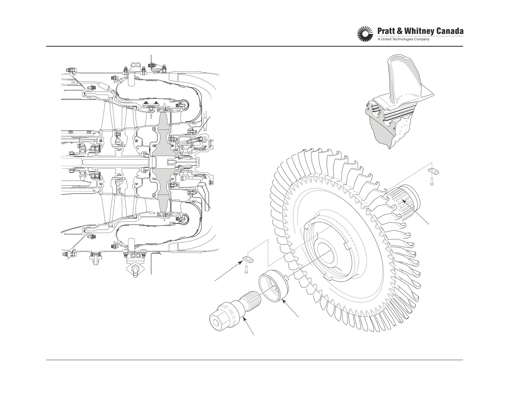
COMPRESSOR TURBINE
MASTER
SPLINE
DETAIL WEIGHT
CUP WASHER
RETAINING BOLT
PT6A-60 SERIES
TRAINING USE ONLY
COMBUSTION & TURBINE 3.11
P&WC Proprietary - Disclosure and use subject to the restrictions on page 2 of preface
COMPRESSOR TURBINE TRIM BALANCING
(64, 66, 67)
Function:
Example:
A residual unbalance remains once the CT is mated with
1st weight -- B 05 L --
the compressor assembly. Adding TRIM weights minimizes
vibration and maintains original compressor rotor balance
B Denotes trim weight class (A,B, C, D, E and G)
during field replacement of the compressor turbine.
05
Number from 01 to 40 denotes position of first rivet
retaining trim weight from number 1 in direction of J
arrow.
Description:
L
Denotes weight offset in relation to first hole occu-
- Detail Balancing (PWC approved facilities only)
pied by weight retaining rivet from number 1 in direc-
- Initial balancing of the compressor turbine using detail
tion of arrow.
weights on the two balancing planes
- Trim Balancing
- H Heavy offset
- After initial detail balancing, the compressor turbine is
- L Light offset
re-balanced with the compressor assembly using
- N No offset (weight symmetrical)
trim weights on the same two balancing planes.
Note:
- The data plate indicate the location of the trim weights
- Trim weights are always installed in pairs facing one
another on the two balancing planes.
- Detail weights are installed by approved facilities only
- Trim weights can be installed by the operator
- An Overhaul Shop or Service Center can install the
trim weights when requested by the operator
PT6A-60 SERIES
TRAINING USE ONLY
COMBUSTION & TURBINE 3.12
P&WC Proprietary - Disclosure and use subject to the restrictions on page 2 of preface
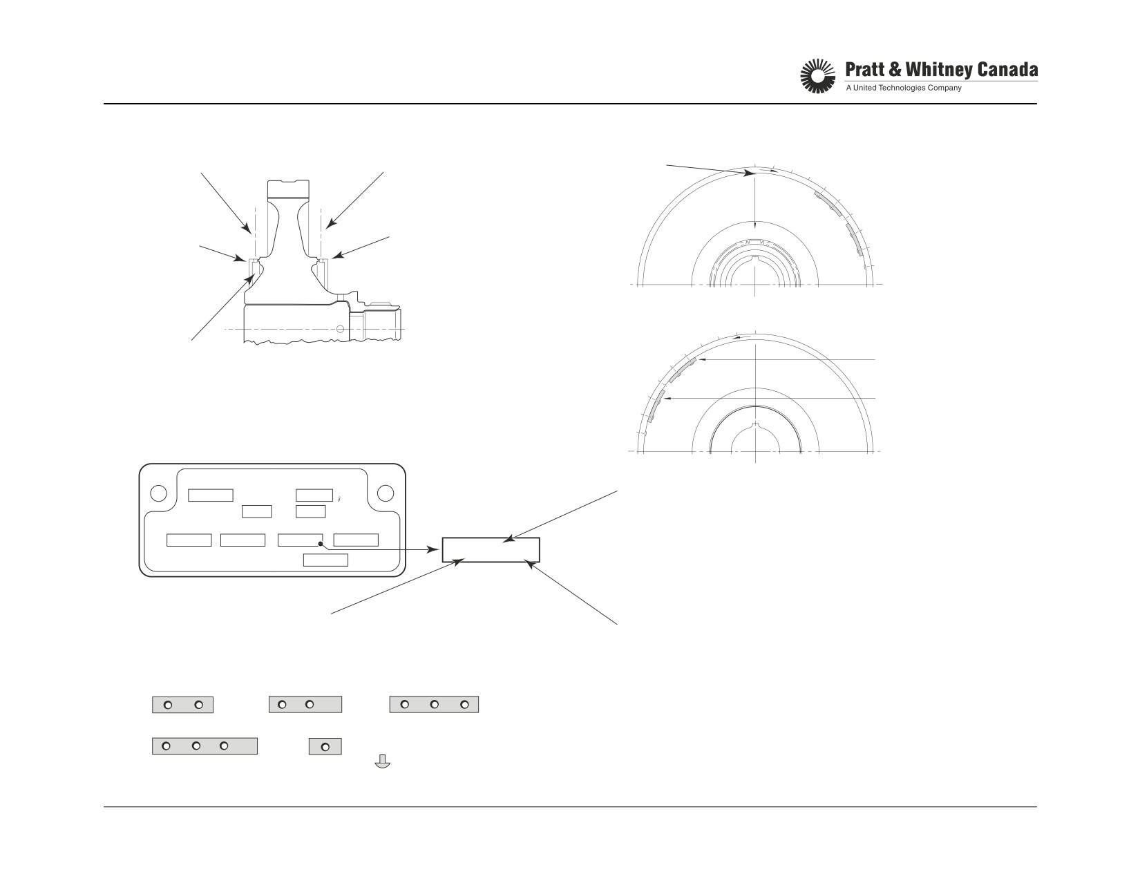
COMPRESSOR TURBINE
TRIM BALANCE WEIGHTS
#1 ALIGNED WITH
1
2
C/T DISK REAR FACE
PLANE B
PLANE A
3
4
MASTER SPLINE
5
6
7
REAR
8
FRONT
9
FACE
FACE
10
2
1
C/T DISK FRONT FACE
3
4
5
MANUFACTURED HEADS
6
LIGHT
ON INSIDE OF RIM, BOTH FACES
7
OFFSET
8
HEAVY
9
OFFSET
10
DATA PLATE
PERFORMANCE REFERENCE DATA
NG
SHP
NUMBER FROM 01 TO 40 DENOTES POSITION OF
35050
AT
1137
√θ
√θ
FIRST RIVET RETAINING TRIM WEIGHT FROM
ITT TRIM
90.2
CO
23
OHMS
THIRD
NUMBER 1 IN DIRECTION OF ARROW.
COMPRESSOR TURBINE TRIM WEIGHTS
WEIGHT
B 05 L
B 08 H
G 10 N
N/R
G 10 N
ENG. BUILD SPEC.
T.C.
DENOTES WEIGHT OFFSET
H. HEAVY OFFSET
IN RELATION TO FIRST
L. LIGHT OFFSET
DENOTES TRIM WEIGHT CLASS
HOLE OCCUPIED BY WEIGHT
N. NO OFFSET
A CLASS 1 C CLASS 3 E CLASS 5
RETAINING RIVET FROM
(WEIGHT SYMMETRICAL)
B CLASS 2 D CLASS 4 G NO WEIGHT, RIVET ONLY
NUMBER 1 IN DIRECTION OF ARROW
A
B
C
CL1
CL2
CL3
D
E
G
CL4
CL5
PT6A-60 SERIES
TRAINING USE ONLY
COMBUSTION & TURBINE 3.13
P&WC Proprietary - Disclosure and use subject to the restrictions on page 2 of preface
ALTERNATE TRIM WEIGHTS (64/66/67)
Function:
Starting from hole no. 4 counter clockwise and from hole
no. 7 clockwise (the weights are installed at holes no. 39
Allows the trim balancing to perform even when the trim
and 40 on one side and holes no. 11 and 12 in the other).
weights location as per the data plate is occupied by detail
Alternatively, 2 class # 1 weights can be installed 6 holes
balancing weights.
away or 2 class # 4 weights can be installed 8 holes away.
For cases where class 2 or class 4 weights must be
Description:
installed as alternate trim weights; try to maintain symmetry
by installing one weight with a light offset and the other with
A table in the maintenance manual provides a choice of
a heavy offset.
alternative location to install the trim weights away from the
position marked on the reference data plate when this posi-
tion is occupied by detail balancing weights. The trim
weight is replaced by a pair of weights that are installed on
each side and equidistant from original trim weight location
(ref. data plate)
Example:
On the turbine illustrated below there is a detail weight at
the positions 5 and 6 so the trim weight B 05 L marked on
the data plate cannot be installed (interference at hole no.
5). According to the table, we can replace a “B” type weight
(class 2) by installing two class # 1 (‘A’) weights, 5 holes
away on each side of the detail weight.
PT6A-60 SERIES
TRAINING USE ONLY
COMBUSTION & TURBINE 3.14
P&WC Proprietary - Disclosure and use subject to the restrictions on page 2 of preface
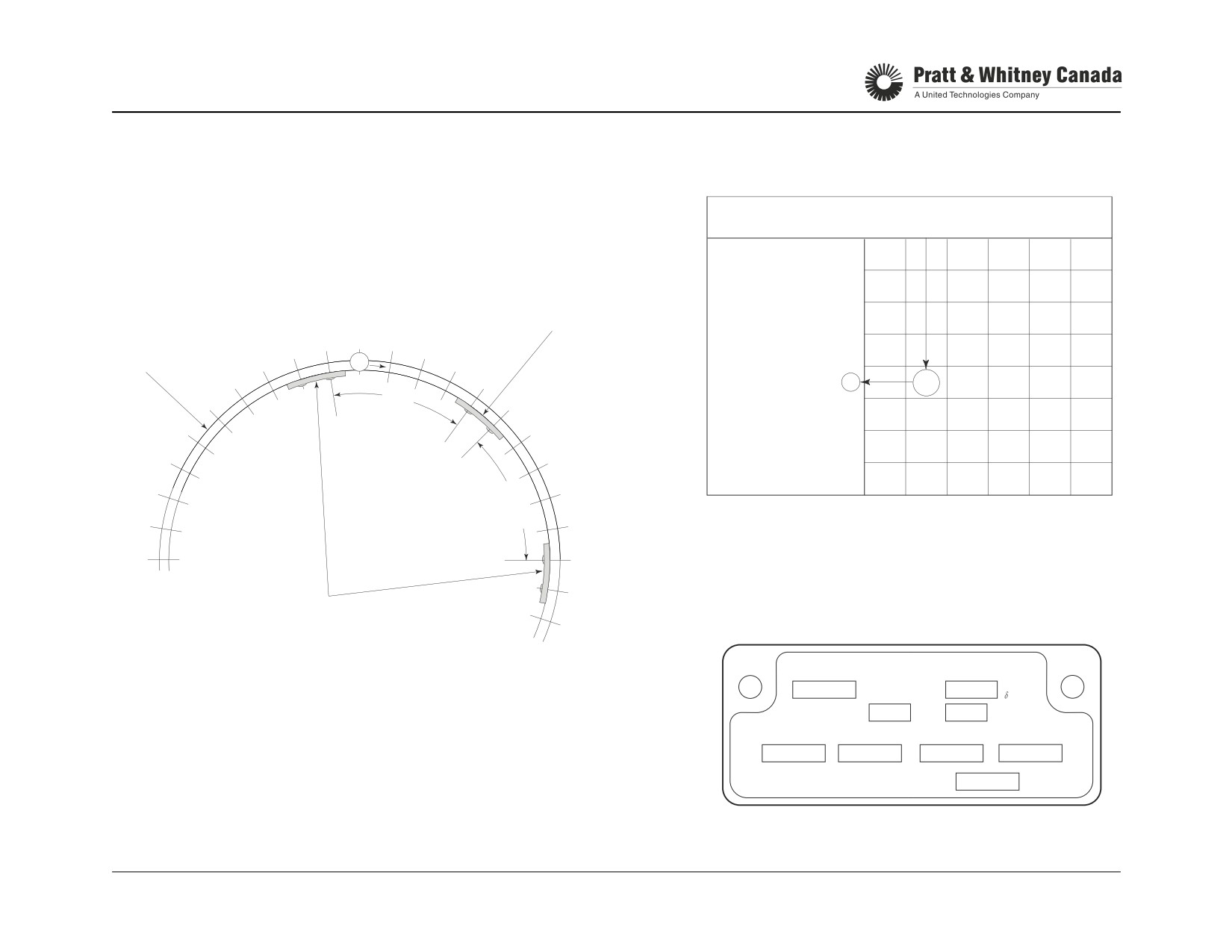
ALTERNATE TRIM WEIGHTS
NOTE: WHEN A NEW DETAIL WEIGHT OCCUPIES A TRIM WEIGHT ORIGINAL LOCATION
TRIM WEIGHT TABLE
(REF. DATA PLATE), ALTERNATIVE TRIM WEIGHTS MUST BE USED IN PAIRS
A
B
C
D
E
G
ONE EACH SIDE OF AND EQUIDISTANT FROM ORIGINAL TRIM WEIGHT LOCATION
TRIM WEIGHT CLASS
CLASS
CLASS
CLASS
CLASS
CLASS
SINGLE
(REF. DATA PLATE).
FROM DATA PLATE
1
2
3
4
5
RIVET
1
CL1
ORIGINAL POSITION OF TRIM
WEIGHT (REF. DATA PLATE),
2
CL1
NOW OCCUPIED BY NEW
DETAIL WEIGHT.
3
CL1
NUMBER OF HOLES
C/T DISK ASSEMBLY
40
2
39
3
EACH SIDE OF
4
CL1
CL2
BALANCING
38
1
4
ORIGINAL TRIM
RIM
37
5
WEIGHT LOCATION
5
CL1
CL1
CL2
5
36
6
HOLES
6
CL1
CL1
CL2
CL3
35
7
SINGLE
7
CL1
CL3
CL4
CL5
RIVET
34
8
8
CL3
CL4
33
9
5
32
HOLES
10
11
12
ALTERNATIVE TRIM WEIGHT LOCATION
DETERMINED USING TRIM WEIGHT TABLE
13
DATA PLATE
PERFORMANCE REFERENCE DATA
NG
SHP
CT DISK ASSEMBLY TRIM WEIGHTS
35050
AT
1137
√θ
√θ
ITT TRIM
90.2
CO
23
OHMS
COMPRESSOR TURBINE TRIM WEIGHTS
B 05 L
B 08 H
G 10 N
N/R
ENG. BUILD SPEC.
T.C.
PT6A-60 SERIES
TRAINING USE ONLY
COMBUSTION & TURBINE 3.15
P&WC Proprietary - Disclosure and use subject to the restrictions on page 2 of preface
POWER TURBINE VANE RINGS
Function:
Operation:
- Direct gases to the first and second stage power tur-
bines at the optimum speed and angle
Gases leaving the compressor turbine are accelerated
- Change static pressure into velocity
through the first and second stage vane rings while causing
their respective power turbines to rotate.
First Stage:
- Riveted centre baffle directs air for cooling onto the
The first and second stage vane rings are held in place by
Compressor turbine disk and the power turbines.
lugs fitted in the power turbine housing. The riveted inner
- Exit area of the vane ring is classified.
baffle directs air close to the power and compressor turbine
- Keep with the Gas Generator as a matched set.
disks for cooling. The selection of different vane areas
allows for optimization of Ng vs. T5 during engine test.
Second Stage:
- Inner section supports an abradable seal.
The second stage vane ring supports an abradable seal
- Both vane rings are supported by the Power Turbine
that diverts cooling air to the two adjacent faces of the
Housing.
power turbines.
- A lug to slot arrangement centralizes and prevents
rotation of the two vane rings.
- Not classified
Replacement:
Replace within ±0.1 sq.in. of the original area from the last
Effect Of Vane Ring Class Change At Constant Power:
test. (Ref. SIL PT6A-032)
Increase area
Ng ↑
T5 ↓
Decrease area
Ng ↓
T5 ↑
PT6A-60 SERIES
TRAINING USE ONLY
COMBUSTION & TURBINE 3.16
P&WC Proprietary - Disclosure and use subject to the restrictions on page 2 of preface

POWER TURBINE VANE RINGS
P.T. VANE RING
T5 PROBE
FIRST STAGE
SLOT
P.T. VANE RING
SECOND STAGE
PT6A-60 SERIES
TRAINING USE ONLY
COMBUSTION & TURBINE 3.17
P&WC Proprietary - Disclosure and use subject to the restrictions on page 2 of preface
POWER TURBINES
Function:
Operation:
Extract energy from the gases to drive the propeller through
The two power turbines extract the energy necessary to
the reduction gearbox.
drive the propeller.
The rotational energy extracted by the power turbine is
Description:
transmitted to the power turbine shaft through splines on
- Turbine disks are machined from nickel alloy
the second stage turbine hub.
- Coupled together by a lug to slot arrangement
- Fir-tree serration’s in the disks support the blades and
Removal of the power turbines is permissible at field level to
allow for thermal expansion differences between the
replace the second stage vane ring. Balancing of the power
disk and the blades
turbines is done with the power turbine shaft and the num-
- Rivets lock the blades in place
ber 3 and 4 bearings, this is the reason why power turbines
- 2nd stage turbine attaches to the power turbine shaft
are not field replaceable.
via splines
- Power turbine blades are shrouded at the tip to form a
solid rim around blade tips and reduce blade vibration
Maintenance:
-
To allow for thinner, more efficient airfoil that offsets
- Inspect the 2nd stage PT blades for cracks. SB 14172
the weight penalty of the shrouded blade tips
-
Pre SB every 1500 hrs.
-
To reduce gas leakage at the tip of the blade
-
Post SB every 4000 hrs.
- No shroud segments, a double knife edge provides
sealing at the blade tip
References:
Max Nf A-52/60/61
30400 rpm
Max Nf A-64
30144 rpm
Max Nf A-66
30400 rpm
Max Nf A-65/67
29930 rpm
PT6A-60 SERIES
TRAINING USE ONLY
COMBUSTION & TURBINE 3.18
P&WC Proprietary - Disclosure and use subject to the restrictions on page 2 of preface

POWER TURBINES
FIRST STAGE
POWER TURBINE
SHROUDED
BLADES
AIR SEAL
SECOND STAGE
POWER TURBINE
PT6A-60 SERIES
TRAINING USE ONLY
COMBUSTION & TURBINE 3.19
P&WC Proprietary - Disclosure and use subject to the restrictions on page 2 of preface
TURBINE WASH
Function:
Sulphidation:
Remove salt deposits from the turbine section of the engine
Sulphidation is a common name for a type of hot corrosion
to minimize sulphidation of the turbine blades.
which can affect turbine area components.
Sulphidation occurs at engine operating temperatures when
Method:
sodium and sulphur are present. All turbine fuels contain
sulphur in sufficient amounts for this chemical reaction to
Motoring wash with turbine wash nozzle inserted in igniter
occur. Common sources of sodium are seawater, atmo-
port. PT6A-67B/D/F/P’s have a dedicated wash port.
spheric pollutants and volcanic discharge.
Sulphidation attacks the CT blades, but it is not uncommon
Description:
for the CT stator and other non-rotating components to be
affected. It can not be detected by performance run data
The washing medium used is drinkable water. It is recom-
analysis.
mended that this procedure be carried out when operating
in a salt laden atmosphere. It is also recommended to per-
Stage 1: Initial coating deterioration. Slight roughen-
form the turbine wash in conjunction with compressor wash.
ing of the surface caused by some growth and break-
It is essential that the compressor section be washed first
down of the oxide layer. Mechanical integrity is not
(refer to compressor section in this manual).
affected.
Water is injected into the turbine section using a turbine
Stage 2: Initial corrosion. Surface roughness is more
wash nozzle through one igniter port. Ensure that the arrow
marked as oxide layer breakdown continues. Mechani-
sign on the tool tang is pointing towards the reduction gear-
cal integrity is not affected.
box.
Stage 3: Advanced corrosion. Oxidation of the base
material has penetrated to significant depth, with obvi-
The procedure to perform the turbine wash is identical to
ous build-up scale. Mechanical integrity seriously
the compressor desalination wash. Refer to the Engine
affected. Progression to Stage 4 will accelerate.
Maintenance Manual chapter 71 for more details.
Stage 4: Severe corrosion. Deep penetration, large
blisters are apparent. Failure is likely due to loss of
structural material.
PT6A-60 SERIES
TRAINING USE ONLY
COMBUSTION & TURBINE 3.20
P&WC Proprietary - Disclosure and use subject to the restrictions on page 2 of preface
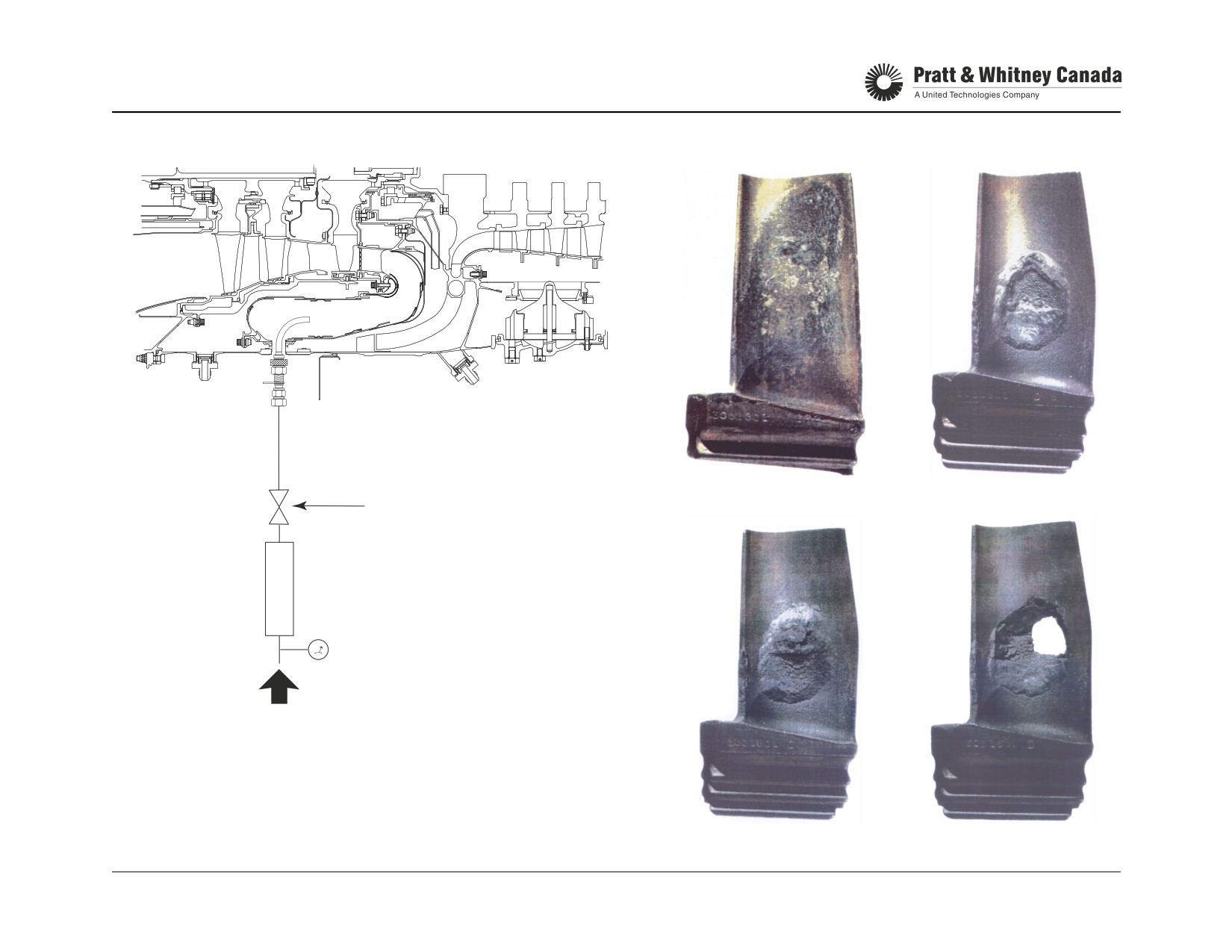
TURBINE WASH
1
2
SHUTOFF
3
4
VALVE
CLEAN OR
DEMINERALIZED
WATER
PRESSURE GAGE
REGULATED
AIR / NITROGEN
PRESSURE
PT6A-60 SERIES
TRAINING USE ONLY
COMBUSTION & TURBINE 3.21
P&WC Proprietary - Disclosure and use subject to the restrictions on page 2 of preface
EXHAUST DUCT & PT SHAFT HOUSING
Exhaust Duct:
- Direct the exhaust gases to ambient atmosphere with
minimum flow restriction
- Welded assembly of heat resistant Nickel alloy sheet
metal
- On the A-67R/A-65AR, the exhaust duct is rotated 30°
to suit the airframe installation (Shorts)
Power Turbine Stator Housing:
- Support the power turbine vane rings, the T5 harness
and thermocouples
- Interfaces with the gas generator section via a seal
ring
Insulation Blanket:
- Minimizes heat transfer between the hot gases and the
reduction gearbox and the power turbine shaft housing
Power Turbine Shaft Housing:
- Support the power turbine shaft
- Forms a cavity for bearing no. 3 and 4
Power Turbine Shaft:
- Supported by bearing no. 3 and 4
- Transmits power turbine speed and torque to the
reduction gearbox via the power turbine shaft coupling
and the reduction gearbox first stage sun gear
PT6A-60 SERIES
TRAINING USE ONLY
COMBUSTION & TURBINE 3.22
P&WC Proprietary - Disclosure and use subject to the restrictions on page 2 of preface

EXHAUST DUCT & PT SHAFT HOUSING
POWER
NO. 3 BEARING
TURBINE
PT SHAFT
SHAFT
HOUSING
POWER TURBINES
POWER TURBINE
STATOR HOUSING
PT SHAFT HOUSING
FLANGE "B"
POWER TURBINE
RGB
INSULATION NO. 4
VANE RINGS
REAR
BLANKET
BEARING
CASE
EXHAUST DUCT
PT6A-60 SERIES
TRAINING USE ONLY
COMBUSTION & TURBINE 3.23
P&WC Proprietary - Disclosure and use subject to the restrictions on page 2 of preface
SEALING OF THE HOT SECTION AREA
(52/60/61/64/65/66/67, A, AF, R)
Function:
Gas sealing in the hot section area is a very important factor affecting hot section life. This section describes the major
sealing surfaces in the hot section and their purposes.
Sealing
Description
Function
Face
A
Vane ring to small exit duct and shroud housing
Prevent P3 air around the combustion chamber to
leak and bypass the vane ring
B
Lock plate to vane ring
Prevent P3 leaks from combustion chamber area to
other side of vane ring
C
Power turbine housing to shroud housing seal
Prevent P3 leaks into P5
D
First stage PT vane to second stage PT vane
Prevent leaks around the second stage vane ring
PT6A-60 SERIES
TRAINING USE ONLY
COMBUSTION & TURBINE 3.24
P&WC Proprietary - Disclosure and use subject to the restrictions on page 2 of preface

HOT SECTION SEALING
B
A
D
C
PT6A-60 SERIES
TRAINING USE ONLY
COMBUSTION & TURBINE 3.25
P&WC Proprietary - Disclosure and use subject to the restrictions on page 2 of preface
SEALING OF THE HOT SECTION AREA
(67AG, 67B, D, F, P, T, 66B, 66D)
Function:
Gas sealing in the hot section area is a very important factor affecting hot section life. This section highlight sealing sur-
faces in the hot section and their functions.
Sealing
Description
Function
Face
A
Lock plate to vane ring
Prevent P3 leaks between combustion chamber
and no. 2 bearing cover area.
B
Small exit duct to shroud housing
Prevent P3 leaks between combustion chamber
and vane ring top section.
C&D
Vane ring to shroud housing
Forms a chamber for vane ring cooling air.
E
Power turbine housing to shroud housing seal
Prevent P3 leaks into P5
ring
F
First stage Power turbine vane to second stage
Prevent leaks around the second stage vane ring.
PT vane
PT6A-60 SERIES
TRAINING USE ONLY
COMBUSTION & TURBINE 3.26
P&WC Proprietary - Disclosure and use subject to the restrictions on page 2 of preface

HOT SECTION SEALING
F
E D C
B
A
PT6A-60 SERIES
TRAINING USE ONLY
COMBUSTION & TURBINE 3.27
P&WC Proprietary - Disclosure and use subject to the restrictions on page 2 of preface
HOT SECTION TROUBLESHOOTING
Problem
Symptoms At Constant Power
Action Required
Ng
T5
Wf
Seal ring leak
Same
Up
Up
Reposition or replace seal ring. Verify
seal ring groove and replace shroud
housing if damaged.
Gas leakage at junction between
Same
Up
Up
Lap sealing faces. Send parts to an
small exit duct and vane ring
approved shop if required to restore
the sealing faces. Replace compress-
ible seals (certain models only)
Burnt CT vane ring (larger throat area)
Down
Up
Up
Replace vane ring
High compressor turbine tip clearance
Down
Up
Up
Replace shroud segments to restore
clearance. Send turbine to overhaul
facility for reblading if necessary.
Eroded compressor turbine blades
Down
Up
Up
Send assembly to an approved facility
for blade replacement.
NOTE:
Hot section problems are all characterized by high T5 and Wf.
Ng usually goes down or remains constant.
PT6A-60 SERIES
TRAINING USE ONLY
COMBUSTION & TURBINE 3.28
P&WC Proprietary - Disclosure and use subject to the restrictions on page 2 of preface
GEARBOXES
GEARBOXES
PT6A-60 SERIES
TRAINING USE ONLY
REDUCTION GEARBOX 4.1
P&WC Proprietary - Disclosure and use subject to the restrictions on page 2 of preface
REDUCTION GEARBOX
Function:
The second stage reduction system is similar to the first
stage but uses five planet gears instead of three. The sec-
Reduce the power turbine speed to a speed suitable for pro-
ond stage gear carrier drives the propeller shaft via splines.
peller operation.
Reverse rotation on the A-66 is achieved by securing the
second stage carrier to the front reduction gear case and
Construction:
allowing the second stage ring gear to rotate.
- Two stage planetary reduction system
- Magnesium front and rear housing
A bevel gear on the propeller shaft provides drive for 3 RGB
mounted accessories:
Reduction Ratios:
1. Propeller Governor (CSU)
2. Propeller Overspeed Governor (A/F)
3. Np Tacho Generator
60A/65/67
A-52/A61/64/66
5.78:1
5.33:1
Maintenance:
1St Stage
- Verify chip detector for metal contamination.
3.04:1
2.83:1
2nd Stage
- Verify reduction gearbox scavenge strainer for metal
contamination.
Overall ratio
17.58:1
15.10:1
- Replace propeller shaft oil seal if leak is evident.
Max. Np (rpm)
1700
2000
- Replace Np Tach-Gen lip seal on RGB accessory
drives
- Touch-up scratches on prop shaft.
- CSU & OSG gaskets
Operation:
-
Field repairs are not allowed inside the reduction gear-
box.
The PT6 engines use a planetary type reduction gearbox
system with two stages of reduction. The first stage con-
sists of a sun gear meshing with three planet gears
mounted in a carrier. The three planet gears mesh on the
outside with a ring gear splined into the reduction gearbox
casing. The first stage gear carrier drives the second stage
sun gear through a flexible coupling arrangement. Provi-
sion to measure torque is provided by the first stage reduc-
tion system.
PT6A-60 SERIES
TRAINING USE ONLY
REDUCTION GEARBOX 4.2
P&WC Proprietary - Disclosure and use subject to the restrictions on page 2 of preface
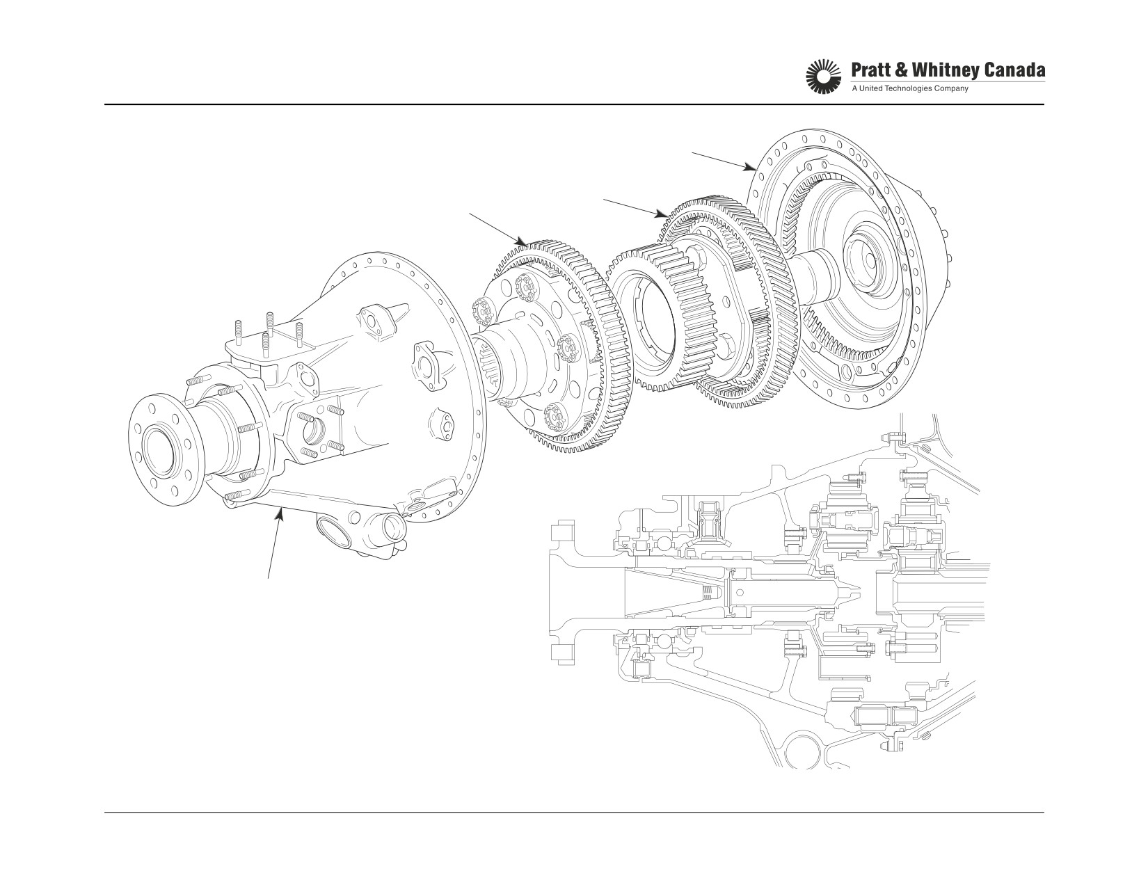
REDUCTION GEARBOX
REAR
HOUSING
1ST STAGE
2ND STAGE
FRONT
HOUSING
PT6A-60 SERIES
TRAINING USE ONLY
REDUCTION GEARBOX 4.3
P&WC Proprietary - Disclosure and use subject to the restrictions on page 2 of preface
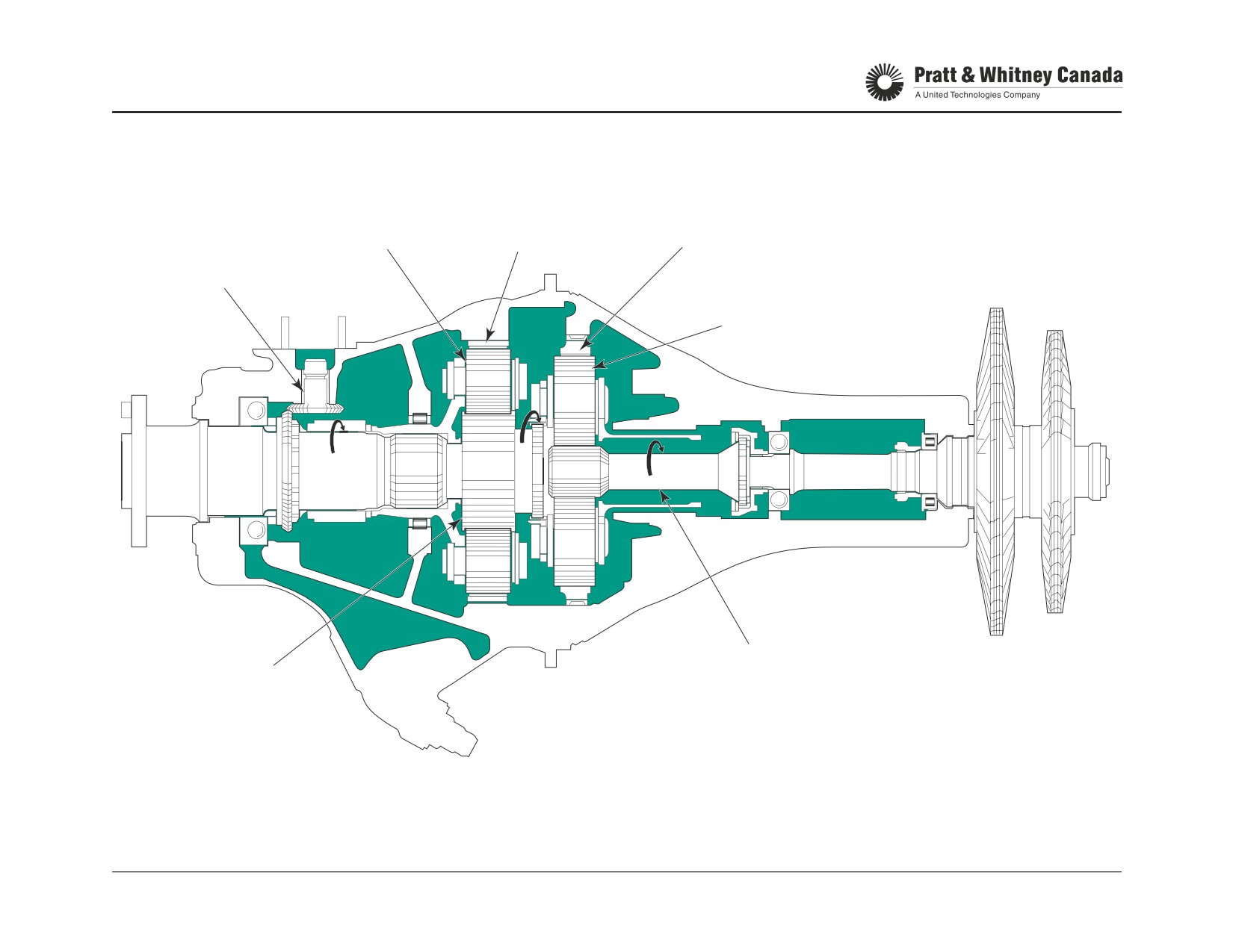
STANDARD ROTATION REDUCTION GEARBOX
SECOND STAGE
SECOND STAGE
PLANET GEAR
FIRST STAGE RING GEAR
RING GEAR
ACC. DRIVES(3)
FIRST STAGE
PLANET GEAR
FIRST STAGE SUN GEAR
SECOND STAGE
SUN GEAR
PT6A-60 SERIES
TRAINING USE ONLY
REDUCTION GEARBOX 4.4
P&WC Proprietary - Disclosure and use subject to the restrictions on page 2 of preface
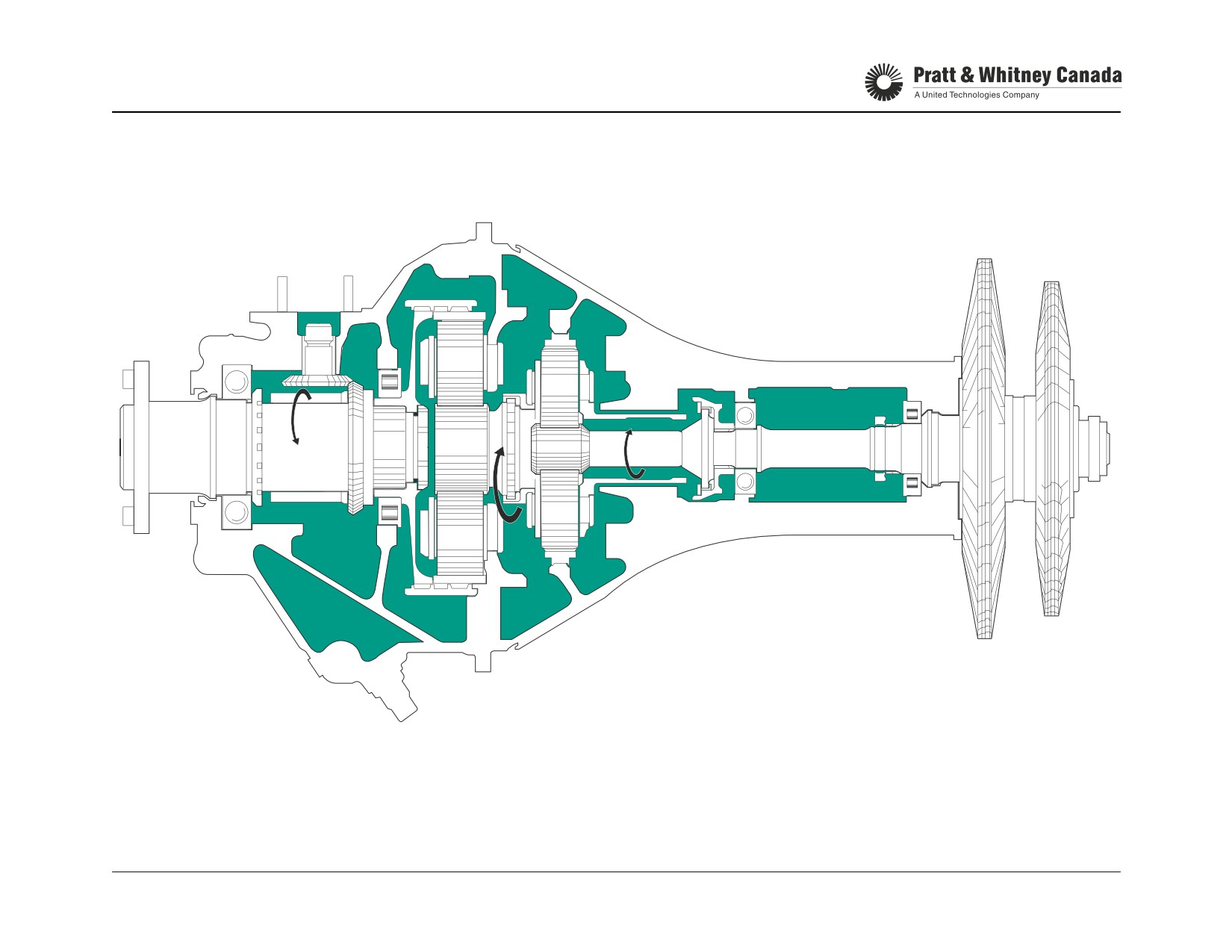
PT6A-66 REVERSE ROTATION GEARBOX
PT6A-60 SERIES
TRAINING USE ONLY
REDUCTION GEARBOX 4.5
P&WC Proprietary - Disclosure and use subject to the restrictions on page 2 of preface
ACCESSORY GEARBOX
Function:
Construction:
- Two light alloy casings (diaphragm and rear hsg.) sup-
Provides drive pads for engine and airframe accessories
port the drive gears.
such as:
- The casings are bolted together and then to the inlet
- Fuel pump and fuel control unit
case.
- Starter-generator
- The front casing (diaphragm) separates and seals the
- Oil pressure and scavenge pumps
accessory gearbox from the oil tank
- Ng tacho-generator
- Optional aircraft accessories
- Centrifugal breather impeller to separate air from oil in
Maintenance:
the accessory gearbox
- On condition
- Replace accessory drive seals
- Replace air/oil separator carbon seal
Forms a housing and supports the following:
- Replace starter drive gear
- Oil filler neck
- Inspect AGB scavenge pump inlet screen
- Electric/standard dipstick
- Oil filter and housing assembly
- Oil pressure pump
- Oil pressure regulating valve
- Cold oil pressure relief valve
PT6A-60 SERIES
TRAINING USE ONLY
REDUCTION GEARBOX 4.6
P&WC Proprietary - Disclosure and use subject to the restrictions on page 2 of preface
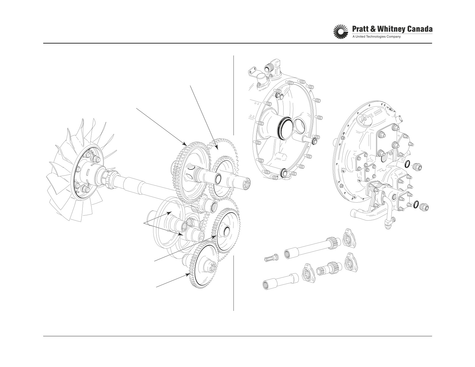
ACCESSORY GEARBOX
FUEL PUMP & FCU GEAR
CENTRIFUGAL BREATHER &
STARTER GENERATORS GEARS
6250
RPM
11000
RPM
7650
RPM
OPTIONAL
4200
ACCESSORY
RPM
DRIVES
PRE-SB14112
MAIN OIL PRESSURE PUMP,
OIL SCAVENGE PUMP &
12000
TACHO-GENERATOR
RPM
EXTERNAL OIL SCAVENGE &
POST-SB14112
3800
OPTIONAL DRIVE
RPM
PT6A-60 SERIES
TRAINING USE ONLY
REDUCTION GEARBOX 4.7
P&WC Proprietary - Disclosure and use subject to the restrictions on page 2 of preface

PIN LOCK ARRANGEMENT
COMPRESSOR HUB
PIN
A.G.B. COUPLING SHAFT
INSERT
SEAL RING
SPRING
SLEEVE
PT6A-60 SERIES
TRAINING USE ONLY
REDUCTION GEARBOX 4.8
P&WC Proprietary - Disclosure and use subject to the restrictions on page 2 of preface
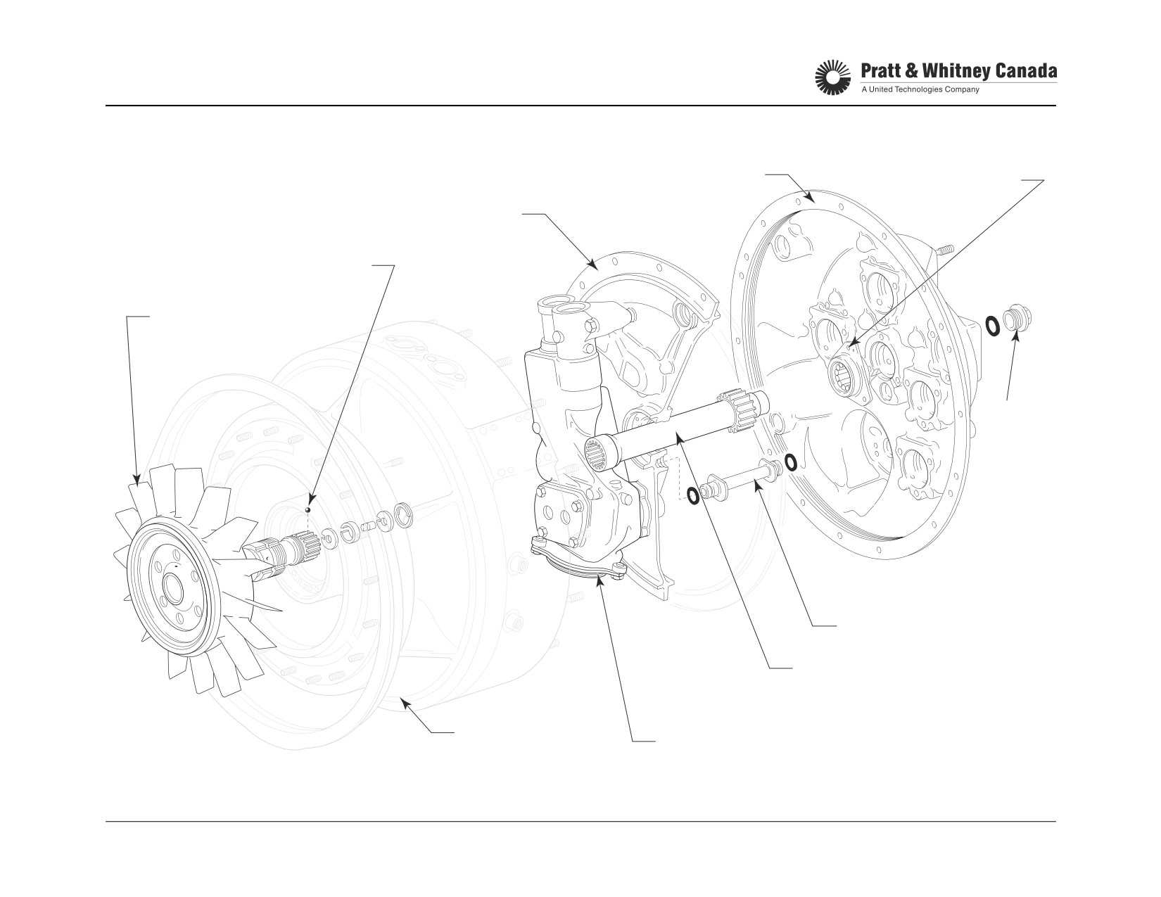
ACCESSORY GEARBOX
BALL-LOCK ARRANGEMENT PRE SB13161
ACCESSORY GEARBOX HOUSING
FLANGED ROLLER
BEARING
ACCESSORY GEARBOX
DIAPHRAGM
BALL LOCK
REAR HUB COMPRESSOR
ASSEMBLY
PLUG
OIL TRANSFER TUBE
GEARBOX INPUT
DRIVESHAFT
INLET CASE
PRESSURE
PUMP
PT6A-60 SERIES
TRAINING USE ONLY
REDUCTION GEARBOX 4.9
P&WC Proprietary - Disclosure and use subject to the restrictions on page 2 of preface
NOTES
PT6A-60 SERIES
TRAINING USE ONLY
REDUCTION GEARBOX 4.10
P&WC Proprietary - Disclosure and use subject to the restrictions on page 2 of preface
OIL SYSTEM
OIL SYSTEM
PT6A-60 SERIES
TRAINING USE ONLY
OIL SYSTEM 5.1
P&WC Proprietary - Disclosure and use subject to the restrictions on page 2 of preface
OIL SYSTEM
Function:
Oil System Flushing:
- Supplies filtered oil to the engine in order to cool, lubri-
- Flush oil system if new type of oil is to be used
cate and clean various components
- Refer to Engine Maintenance Manual for flushing pro-
- Provides oil to the propeller governor to allow propeller
cedure
pitch and speed control.
- Changing from Type II to Type II Third Generation oil
- Provides oil to the torque measurement system
can only be done with new or newly overhauled
engines
Description:
The engine oil system consists of a pressure system, a
Oil Temperature Limits (Typical):
scavenge system and a breather system. The PT6 lubrica-
tion system provides a constant supply of clean oil to the
Starting:
- 40° C min
engine bearings, reduction gears, accessory drives,
Take off:
0° C - 110° C
torquemeter and propeller governor. The oil tank is inte-
Recommend oil temp:
74° C - 80° C
grated in the engine air inlet casing. The oil lubricates and
cools bearings and carries any extraneous matter to the oil
Note:
filter where it is precluded from further circulation. A chip
Refer to engine Maintenance Manual for specific limits.
detector is located on the reduction gearbox to detect metal
particles and warn operators of metal contamination.
Max Oil Consumption:
- 0.3 lb/hr oil consumption
Servicing:
- measured over a 10 hour period
- Use approved synthetic oil listed in SB 13001 and
- (3 lb/10 hr.) (2 lb/10 hr. for A-52/60/61/66)
14001.
- Check oil level within 15-20 minutes after shut down.
- If more than 30 minutes have elapsed before checking
References:
oil level, and dipstick shows oil is needed, run engine
prior to adding oil.
3 lbs
1.5 U.S. qt
- Oil changes required as specified by the Airframe
Oil tank capacity
2.5 U.S. gal
maintenance manual.
Oil tank expansion space
0.7 U.S. gal
- Ensure that oil pressure is within limits (approx. 90-135
Oil tank usable quantity
1.5 U.S. gal
PSIG). Check with NG above 72%.
PT6A-60 SERIES
TRAINING USE ONLY
OIL SYSTEM 5.2
P&WC Proprietary - Disclosure and use subject to the restrictions on page 2 of preface

OIL SYSTEM (BOTTOM VIEW)
OIL TO AIRFRAME
COOLER
OIL PRESSURE LINE
OIL OUT
TO COOLER
RGB & PROPELLER
NO. 2 BEARING
NO. 3 & 4 BEARING
SCAVENGE
PRESSURE
PT6A-60 SERIES
TRAINING USE ONLY
OIL SYSTEM 5.3
P&WC Proprietary - Disclosure and use subject to the restrictions on page 2 of preface
OIL SYSTEM
Pressure System:
The accessory gearbox receives oil from the No. 1, 2, 3 and
4 bearings scavenge systems. From there, the oil is routed
Oil is drawn from the oil tank through a gear type pump and
to the fuel heater by the AGB scavenge pump.
is delivered to the oil filter and Pressure Regulating Valve.
At the filter outlet, pressure oil separates into several paths.
From the outlet of the fuel heater, the oil is directed to the
thermostatic bypass valve. Depending on the oil tempera-
The no. 1 bearing and accessory input drive shaft are lubri-
ture, the thermostatic bypass valve directs the oil to either
cated with oil directed through cored passages and transfer
the oil tank or the airframe oil cooler.
tubes. The oil pressure transmitter and the oil temperature
bulb are mounted on ports located on this internal passage.
The oil coming back from the airframe oil cooler gets back
to the tank through an anti-splashing adapter at the top of
A single tube located at the bottom right hand side of the
the tank.
engine, delivers oil to lubricate the no. 2, 3 and 4 bearings,
the reduction gearbox, front accessories and then to the
propeller and torque measurement systems.
Scavenge System:
The scavenge system consist of four gear type pumps
assembled in two double elements. Two pumps are located
inside the accessory gearbox while the other two are
mounted externally at the rear of the accessory gearbox.
No. 1 bearing scavenges into the accessory gearbox by
gravity. No. 2 bearing scavenge through a tube mounted
underneath the engine. At high power a relief valve
mounted on the line near the scavenge pumps allows air/oil
from the bearing cavity to bleed into the accessory gearbox,
preventing flooding of the number 2 bearing cavity.
PT6A-60 SERIES
TRAINING USE ONLY
OIL SYSTEM 5.4
P&WC Proprietary - Disclosure and use subject to the restrictions on page 2 of preface
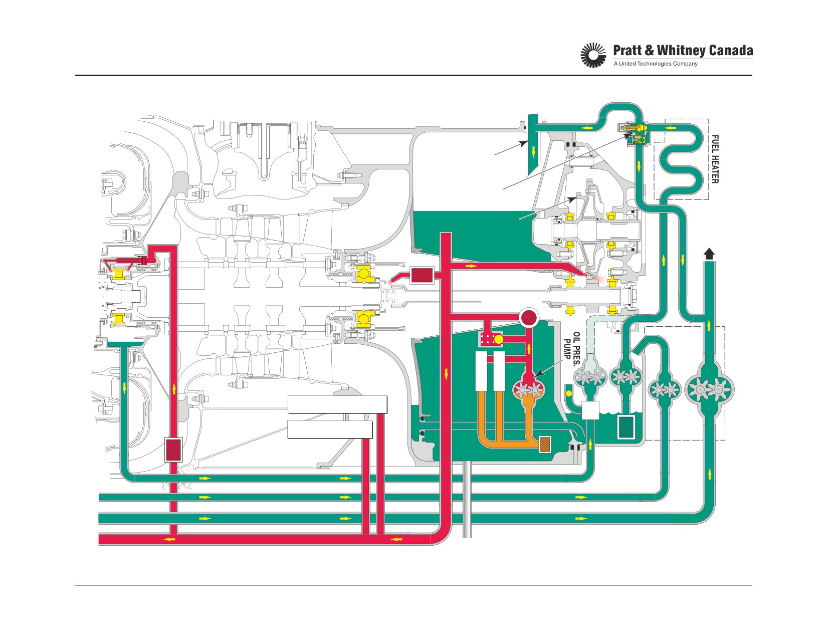
OIL SYSTEM (REAR)
OIL IN FROM
AIRFRAME
COOLER
THERMOSTATIC BYPASS
& CHECK VALVE
CENTRIFUGAL
TO OIL
BREATHER
AIRFRAME
COOLER
MAIN OIL FILTER
C
P
P
R
R
V
V
PRESSURE TRANSMITTER
TEMP. BULB
SCAVENGE OIL
TANK DRAIN
OIL SUPPLY TO PROPELLER & REDUCTION
PT6A-60 SERIES
TRAINING USE ONLY
OIL SYSTEM 5.5
P&WC Proprietary - Disclosure and use subject to the restrictions on page 2 of preface
OIL SYSTEM (CONT’D)
No. 3 and 4 bearing area scavenge into the accessory
gearbox via a scavenge tube mounted on the left-hand side
of the engine. Oil is scavenged by one of the externally
mounted pumps located at the rear of the accessory
gearbox.
The reduction gearbox and the propeller oil system are
scavenged through an external tube located beside the No.
3 and 4 bearing scavenge tube. The oil is pumped by the
second externally mounted scavenge pump and goes
directly to the airframe oil cooler.
Note:
The PT6A- 64/66/67/67A/AF/AG/B/D/F/P/R scavenge
system differs from the other engines. The No. 2 bearing
scavenge pump sends oil directly to the fuel heater and
diverter valve instead of sending it to the accessory
gearbox. (post SB 14108)
PT6A-60 SERIES
TRAINING USE ONLY
OIL SYSTEM 5.6
P&WC Proprietary - Disclosure and use subject to the restrictions on page 2 of preface

OIL PRESSURE REGULATION & FILTRATION
Oil Pump:
Filter:
- Gear type
- 15 micron filter with 40 micron internal screen.
- Inlet screen protects the pump
- Clean electro-sonically only (post SB 13412 and
14392 are not cleanable).
- Inspect every 100 hours.
Pressure Regulating Valve:
- Discard at 1000 hours
- Maintains engine oil pressure within specified limits
(90 - 135 PSI) (100 - 135 PSI for PT6A-52/60/61/64
/66).
Filter Bypass Valve:
- When oil pressure increases above the spring tension,
- Bypasses oil if the oil filter becomes restricted
the valve moves up, opening a passage to the inlet of
- Valve opens when pressure inside the oil filter is 24 psi
the pump, thereby limiting the oil pressure
lower than the pump pressure
- Allows oil to flow through the secondary filter and to
engine lubrication system
Cold Oil Pressure Relief Valve:
- At this point, indicated oil pressure is lower than nor-
- Controls excessive pressure build up during cold
mal (24 psid)
weather starting
- When the pressure regulating valve is fully open and
oil pressure keeps increasing, the cold oil valve opens
Maintenance:
to dump more oil back to the pump
- Service oil tank
- The relief valve opens at 160 psid
- Check chip detector for presence of metal
- Maintain oil pressure within limits
- Inspect and clean oil filter
Filter Check Valve:
- Replace oil filter at 1000 hr
- Opens at a 15 psid to allow oil flow to the filter.
- Replace oil if operated above max oil temperature
- Prevents static oil transfer from the oil tank to the pres-
- Min oil pressure @IDLE : 60 psi
sure system and AGB.
- Inspection of the oil filter without draining the oil tank
PT6A-60 SERIES
TRAINING USE ONLY
OIL SYSTEM 5.8
P&WC Proprietary - Disclosure and use subject to the restrictions on page 2 of preface
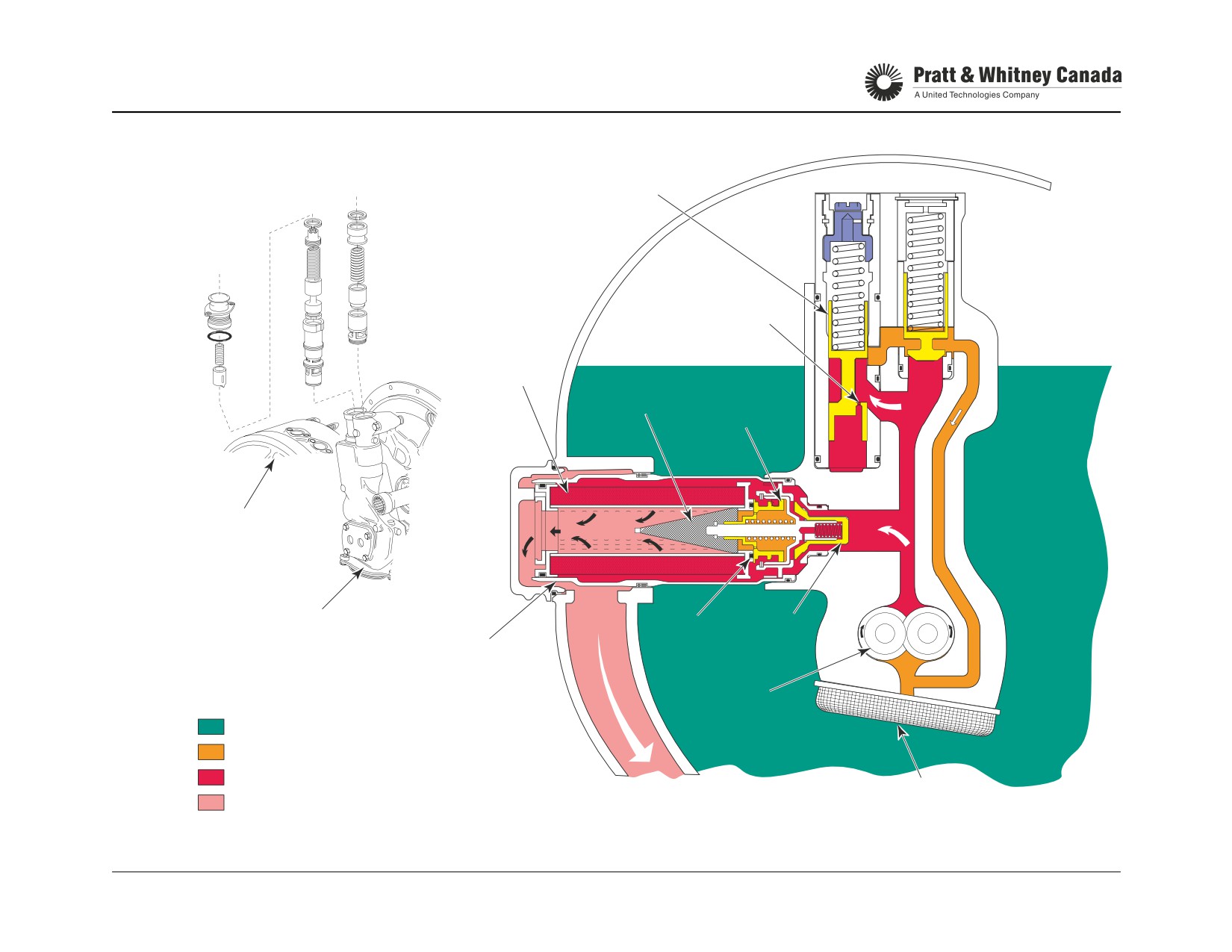
OIL PRESSURE REGULATION & FILTRATION
PRESSURE
REGULATING VALVE
COLD OIL
PRESSURE
RELIEF VALVE
BLEED
ORIFICE
FILTER
SECONDARY
BYPASS
FILTER
VALVE
INLET CASE
REF
OIL PUMP
`O`RING
CHECK
FILTER
VALVE
HOUSING
OIL PUMP
GEARS
OIL
BY PASS OIL
PRESSURE OIL
TO PRESSURE
INLET
FILTERED PRESSURE OIL
SYSTEM
SCREEN
PT6A-60 SERIES
TRAINING USE ONLY
OIL SYSTEM 5.9
P&WC Proprietary - Disclosure and use subject to the restrictions on page 2 of preface
THERMOSTATIC BYPASS & CHECK VALVE
Function:
The check valve opens when the oil pressure coming from
the fuel heater is higher than the pressure of the scavenge
Bring oil to normal operating temperature faster during first
oil from the reduction gearbox by 5 psi. This allows the oil
few minutes of engine operation.
from the fuel heater to mix with the reduction gearbox scav-
enge oil and go to the airframe before it returns to the tank.
Description:
If the bypass valve fails to open at low oil temperatures then
- Mounted on the inlet case
oil pressure will build up and force the check valve to open.
- Consists of a housing, a thermostatic valve and a
check valve
If the check valve can not open, the relief spring of the ther-
mostatic bypass valve bypasses oil from the fuel heater to
the tank, even if the expansive material is fully expanded, to
Operation:
prevent over pressurization and over loading of the acces-
sory gearbox scavenge pump. A pressure of 40 to 55 PSID
Oil coming out from the fuel heater is directed to the ther-
is necessary to overcome the relief spring.
mostatic bypass and check valve. The thermostatic ele-
ment contracts when the oil is cold. This allows the oil to
return to the tank instead of going to the airframe oil cooler.
Maintenance:
Thermal element can be replaced in the field if defective.
The check valve prevents back flow of the scavenge oil from
Check valve may be lapped in the field.
the reduction gearbox to the tank through the thermostatic
bypass valve. As the oil warms-up, the thermostatic ele-
ment expands to gradually close the bypass valve. It begins
Troubleshooting:
to close when the oil temperature reaches approximately
- Oil taking too long to reach normal operating tempera-
60° C and is fully closed around 72° C. As the bypass valve
ture may be caused by faulty thermostatic element
closes, the oil is forced towards the check valve.
- Oil temperature higher than normal may be caused by
faulty thermostatic valve and/or check valve stuck
closed.
PT6A-60 SERIES
TRAINING USE ONLY
OIL SYSTEM 5.10
P&WC Proprietary - Disclosure and use subject to the restrictions on page 2 of preface
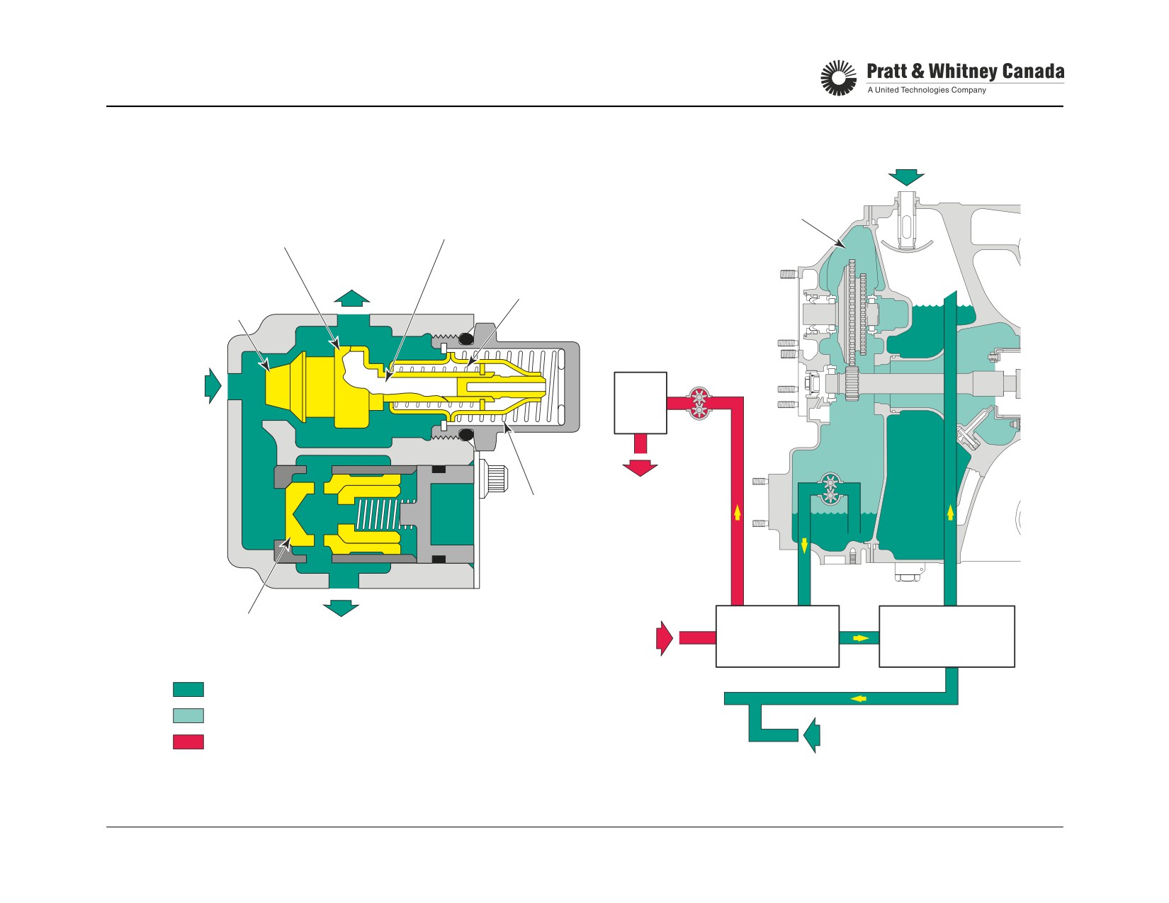
THERMOSTATIC BYPASS & CHECK VALVE
RETURN FROM COOLER
EXPANSIVE
AGB
THERMOSTATIC
MATERIAL
ELEMENT
OIL OUT
OIL
TO TANK
TANK
RETURN
BYPASS
SPRING
VALVE
OIL
FROM
AGB
FCU
SCAVENGE
RELIEF
FUEL
SPRING
OUT
CHECK
OIL OUT TO
THERMOSTATIC
FUEL IN
FUEL HEATER
VALVE
AIR FRAME COOLER
BYPASS
SCAVENGE OIL
OUT TO COOLER
AIR & OIL MIST
RGB SCAVENGE
AIRCRAFT BOOST FUEL PRESSURE
PT6A-60 SERIES
TRAINING USE ONLY
OIL SYSTEM 5.11
P&WC Proprietary - Disclosure and use subject to the restrictions on page 2 of preface
OIL SYSTEM TROUBLESHOOTING
Symptoms
Possible Cause And Fix
High Oil Pressure
Check indicating system
Adjust/verify pressure regulating valve.
Low Oil Pressure
Clean/replace oil filter
Check indicating system
Cracked oil pump housing
Adjust pressure regulating valve
Oil Pressure Fluctuation
Check oil level
Check indicating system
Check oil tank pressurizing valve
Replace/Clean pressure regulating valve
High Oil Temperature
Check oil temperature indicating system
Check airframe oil cooler
Check thermostatic bypass and check valve
Check scavenge pump inlet for blocage
PT6A-60 SERIES
TRAINING USE ONLY
OIL SYSTEM 5.12
P&WC Proprietary - Disclosure and use subject to the restrictions on page 2 of preface
OIL SYSTEM TROUBLESHOOTING (CONT’D))
Symptoms
Possible Cause And Fix
Excessive Oil Discharged From
Oil level kept too high.
Overboard Breather
Verify oil filter check valve (static transfer, blown out during start).
Check O-rings between oil filter housing and inlet case (static transfer)
Verify/replace centrifugal breather carbon seal in accessory gearbox.
Check pressure pump drive seal (static transfer blown out during start).
Check AGB scavenge pump screen for blockage (flooding of AGB).
Excessive Oil Consumption
All of the above.
Check for oil external leaks.
Ensure oil is not transferring into AGB & leaking out of Inlet/BOV.
Check for traces of oil in the exhaust (#3 brg. lab. seal leaking).
Check oil to fuel heater for internal leakage.
Oil Leak From Intake
Check O-ring and Teflon® ring on oil filter housing.
(Oil Transfer To AGB)
Check oil filter check valve for leakage.
Main oil pump lip seal.
Check for broken O-rings in AGB.
Oil Pressure Follows Power Lever
Check Main Oil Pump Housing for correct assembly torque or cracks.
PT6A-60 SERIES
TRAINING USE ONLY
OIL SYSTEM 5.13
P&WC Proprietary - Disclosure and use subject to the restrictions on page 2 of preface
NOTES
PT6A-60 SERIES
TRAINING USE ONLY
OIL SYSTEM 5.14
P&WC Proprietary - Disclosure and use subject to the restrictions on page 2 of preface
SECONDARY AIR SYSTEM
SECONDARY AIR SYSTEM
PT6A-60 SERIES
TRAINING USE ONLY
ENGINE INDICATING 6.1
P&WC Proprietary - Disclosure and use subject to the restrictions on page 2 of preface
SECONDARY AIR SYSTEM
General:
The secondary air system consists of all the compressor air
that is not used to sustain combustion or for airframe use.
Of all the air entering the engine the combustion process
uses only 25%, 65% cools the combustion gases, the air-
frame uses 5% and the secondary air system uses the
remaining 5%.
The Secondary Air System Provides Pressure Air For:
- Cooling of hot section parts
- Sealing of bearing compartment
- Operates bleed valve and pre-swirl (jet flap)
- Operates fuel purge valve
- Operates fuel control unit (P3 Filter)
Two sources of air used in the secondary air system:
P2.5 Compressor Inter-stage air pressure
P3 Compressor delivery pressure
This Section Is Divided Into 4 Parts:
1. Accessory gearbox breather
2. Oil tank pressurizing valve
3. Turbine cooling
4. Bearing compartment sealing
PT6A-60 SERIES
TRAINING USE ONLY
ENGINE INDICATING 6.2
P&WC Proprietary - Disclosure and use subject to the restrictions on page 2 of preface

SECONDARY AIR SYSTEM
P2.5
P3
PT6A-60 SERIES
TRAINING USE ONLY
ENGINE INDICATING 6.3
P&WC Proprietary - Disclosure and use subject to the restrictions on page 2 of preface
ACCESSORY GEARBOX BREATHER
Function:
The relatively oil free breather air flows through the center
of the impeller and out to the atmosphere via a cored pas-
Separates oil particles from air in the accessory gearbox
sage in the accessory gearbox diaphragm.
before discharging overboard.
Maintenance:
Description:
- On condition
- Centrifugal impeller
- Replace carbon seal
- Mounted on the starter generator gear shaft
- Starter generator gearshaft front end is sealed with a
Blocked Or Restricted Breather Hose May:
carbon face seal
- Cause loss of oil through No. 1, 2 and 3 bearing cavi-
ties
- Cause oil leak at flange "G"
Operation:
- Cause accessory drive seals to leak
- Increase oil consumption
Oil and air scavenged from the bearing cavities are directed
- Cause an oil smell in the cabin
to the accessory gearbox. The air/oil combination in the
accessory gearbox causes foaming of the oil. The continu-
ous flow of scavenged air and oil causes the accessory
gearbox to pressurize. Prior to venting the air to the atmo-
sphere, the oil must be separated from the air.
The pressure builds up in the accessory gearbox forces the
air/oil mixture inside the breather impeller. The centrifugal
force imparted by the impeller causes the heavier oil parti-
cles to be ejected back into the accessory gearbox.
PT6A-60 SERIES
TRAINING USE ONLY
ENGINE INDICATING 6.4
P&WC Proprietary - Disclosure and use subject to the restrictions on page 2 of preface

ACCESSORY GEARBOX BREATHER
STARTER / GENERATOR
GEAR
CARRIER
CARBON SEAL
BREATHER
IMPELLER
CARBON SEAL
BREATHER
IMPELLER
CARRIER
CARBON SEAL
AIR
AIR / OIL MIX
PT6A-60 SERIES
TRAINING USE ONLY
ENGINE INDICATING 6.5
P&WC Proprietary - Disclosure and use subject to the restrictions on page 2 of preface
OIL TANK PRESSURIZING VALVE
Function:
The oil tank pressurizing valve maintains air pressure in the
tank 5 to 7 psi above the accessory gearbox pressure. This
Reduces oil pressure fluctuation and oil consumption at
positive pressure applied on the oil reduces pressure fluctu-
high altitude.
ation and oil consumption at altitude.
When static pressure in the tank reaches the specified limit,
Description:
the piston compresses the spring, allowing oil tank air pres-
- Valve seat and spring loaded piston
sure to flow into the accessory gearbox. From the acces-
- Located in the inlet case (oil tank) at the 11 o'clock
sory gearbox, air flows through the centrifugal impeller and
position
out to the atmosphere.
- Maintains the oil tank pressure 5 to 7 psi above acces-
sory gearbox pressure
Troubleshooting:
Operation:
Oil loss through overboard breather tube or the pressurizing
valve being stuck open may cause oil pressure fluctuation
During normal operation, oil scavenge system collects air
at altitude.
and oil from various bearing cavities. The accessory gear-
box breather removes most of the air contained in the oil but
some air remains trapped in the oil.
Maintenance:
- On condition
When air and oil are carried from the cooler to the tank, it
- Remove and inspect valve
causes oil in the tank to foam. Foaming may cause cavita-
- Ensure freedom of movement
tion of the pressure pump and fluctuation of oil pressure at
- Lap piston and seat
high altitude.
As altitude increases, air pressure in the tank drops and
causes air trapped in the oil to expand (foam) and fill the
tank completely. At this point, the excess foam transfers to
the accessory gearbox thus causing an increase in oil loss
through the centrifugal breather.
PT6A-60 SERIES
TRAINING USE ONLY
ENGINE INDICATING 6.6
P&WC Proprietary - Disclosure and use subject to the restrictions on page 2 of preface
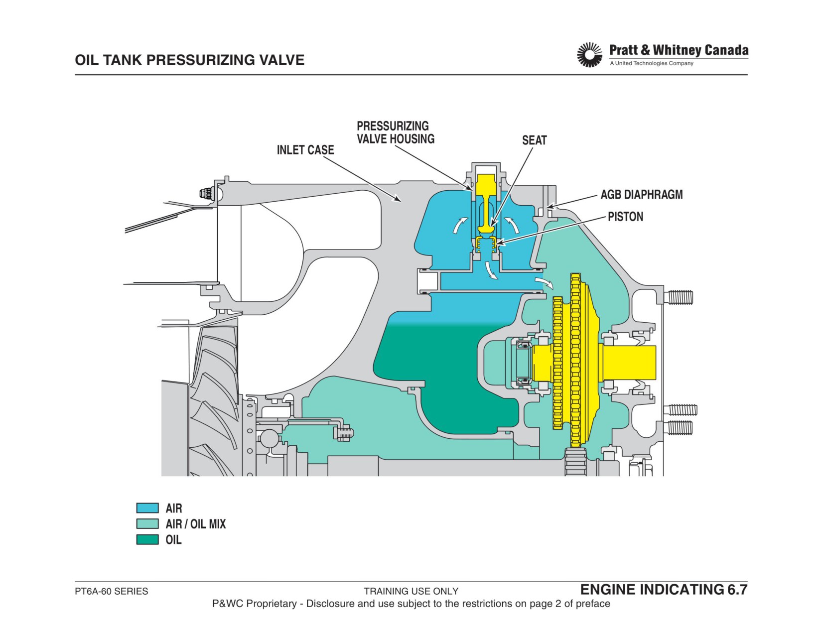
TURBINE COOLING AND AIRBLEED SYSTEM
Description:
Internal passages in the engine distribute P3 air to provide
cooling to the combustion chamber turbine and vane rings.
After cooling, the air is evacuated in the gas path.
Using the same distribution passages, P2.5 and P3 air are
provided to the no. 1, 2 and 3 bearing labyrinth seals. Air
flows into the bearing compartments is evacuated via the oil
scavenge system and discharged overboard through the
centrifugal breather impeller located in the accessory gear-
box.
Tapping on the gas generator case provides P2.5 and/or P3
air for external systems such as cabin environmental con-
trol system, de-icing system, door sealing, etc...
Maintenance And Troubleshooting:
- Keep P3 and P2.5 leaks to a minimum
- (performance losses)
- Ensure cooling rings in the combustion chamber are in
satisfactory condition
- Ensure no leak exists on airframe air bleed system
PT6A-60 SERIES
TRAINING USE ONLY
ENGINE INDICATING 6.8
P&WC Proprietary - Disclosure and use subject to the restrictions on page 2 of preface
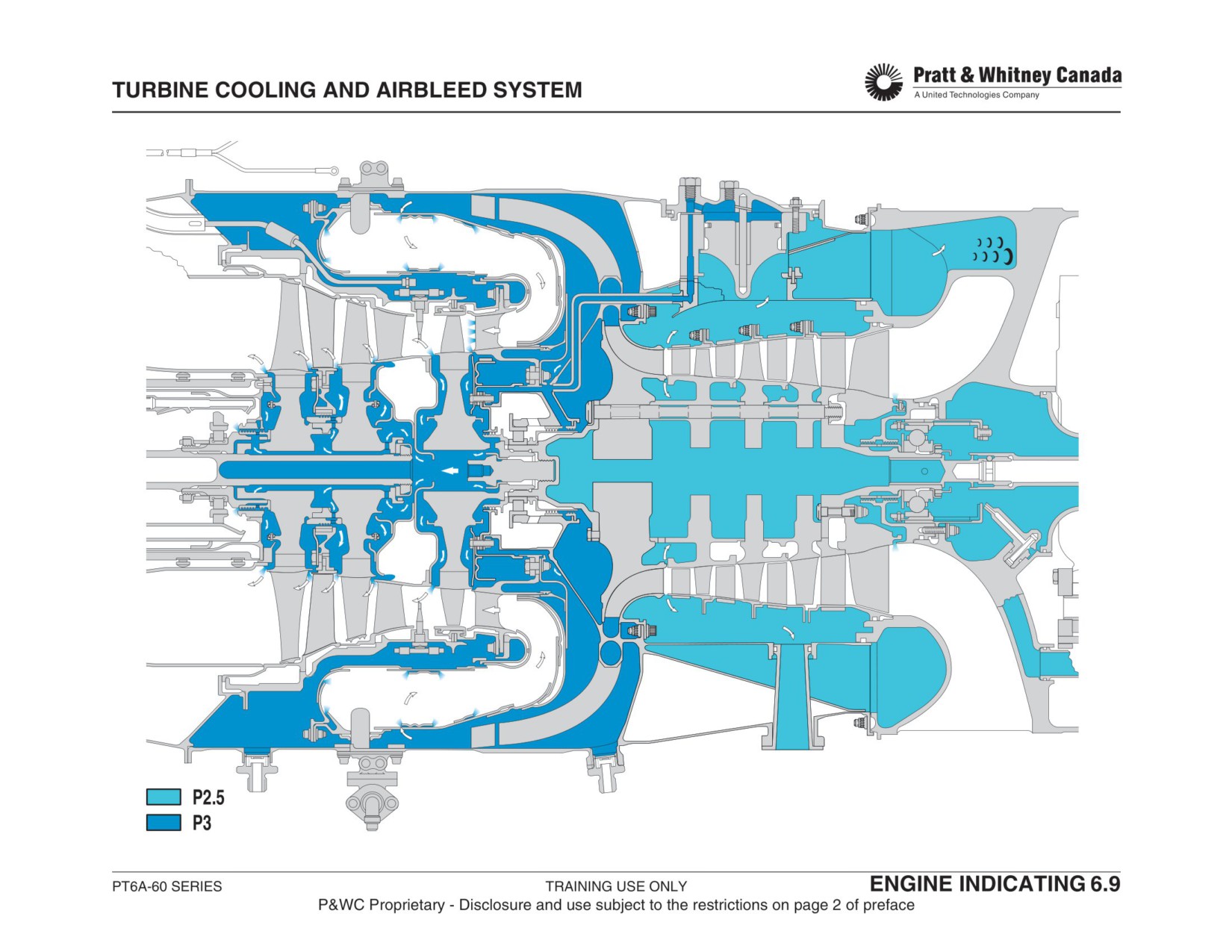
BEARING COMPARTMENT SEALING
Function:
Possible Cause For Oil Loss Through Labyrinth Seals:
- Lack of air flow through labyrinth seal (Not probable)
Prevents oil from leaking outside the bearing cavities.
- Wear on the knife's edges due to rotor unbalance or
bearing distress
Description:
- Oil coking in the grooves between the knife's edges
- Labyrinth seals
- Flooding of bearing cavity due to malfunction in the oil
- Consists of a multi-grooved ring running within a
scavenge system (most probable)
straight stator ring
- Air pressure fills the air gap between the two parts
Problem Area
Symptom
Operation:
No. 1 Bearing
Oil smell in cabin
Oily bleed valve and compressor
The air seal consists of two separate parts, one stationary
No. 2 Bearing
Oil smell in cabin
and one rotating. One of the two parts has machined
(Rear)
grooves. A small clearance is maintained between the two
parts and air pressure is blowing between them creating a
No. 2 Bearing
Coking around no. 2
high velocity air flow that draws the oil towards the inside of
(Front)
bearing and compressor turbine
the bearing cavity.
area
Possible smoke on start and shut-
down
Maintenance:
- None
No. 3 Bearing
Possible smoke on start and shut-
- During HSI, ensure holes in the number 2 bearing
down
area of gas Generator are not blocked
Oil in exhaust duct
- Keep accessory gearbox breather outlet free of
obstruction
- Do not over service the oil tank
PT6A-60 SERIES
TRAINING USE ONLY
ENGINE INDICATING 6.10
P&WC Proprietary - Disclosure and use subject to the restrictions on page 2 of preface
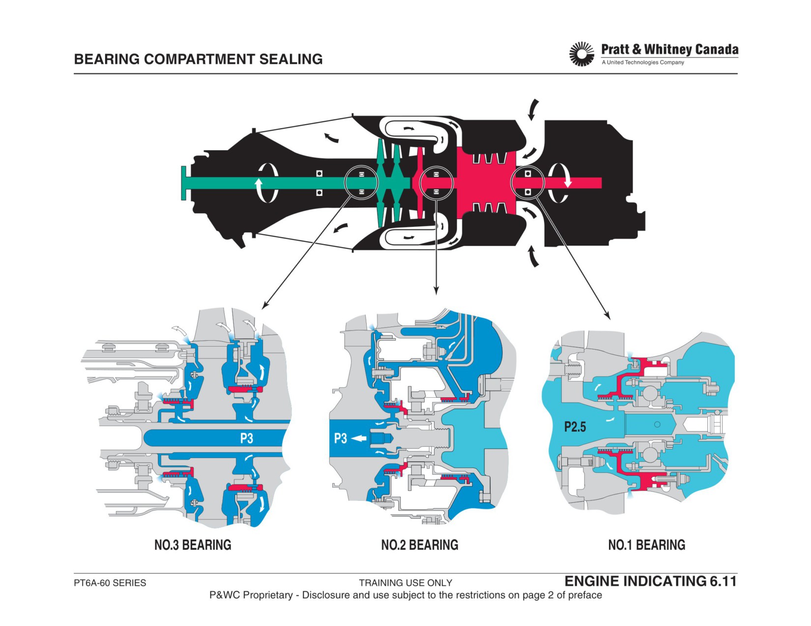
ENGINE INDICATING SYSTEM
ENGINE INDICATING SYSTEM
PT6A-60 SERIES
TRAINING USE ONLY
ENGINE INDICATING SYSTEM 7.1
P&WC Proprietary - Disclosure and use subject to the restrictions on page 2 of preface
//////////////////////////////////////////