JEPPESEN GENERAL AIRWAY MANUAL (Issue Date 1 JUL 21) - page 42
 

  Index      Manuals     JEPPESEN GENERAL AIRWAY MANUAL (Issue Date 1 JUL 21)


Search            copyright infringement  


Content      ..     40      41      42      43     ..


JEPPESEN GENERAL AIRWAY MANUAL (Issue Date 1 JUL 21) - page 42


INTERNATIONAL CIVIL AVIATION ORGANIZATION -

AIR TRAFFIC MANAGEMENT

1313

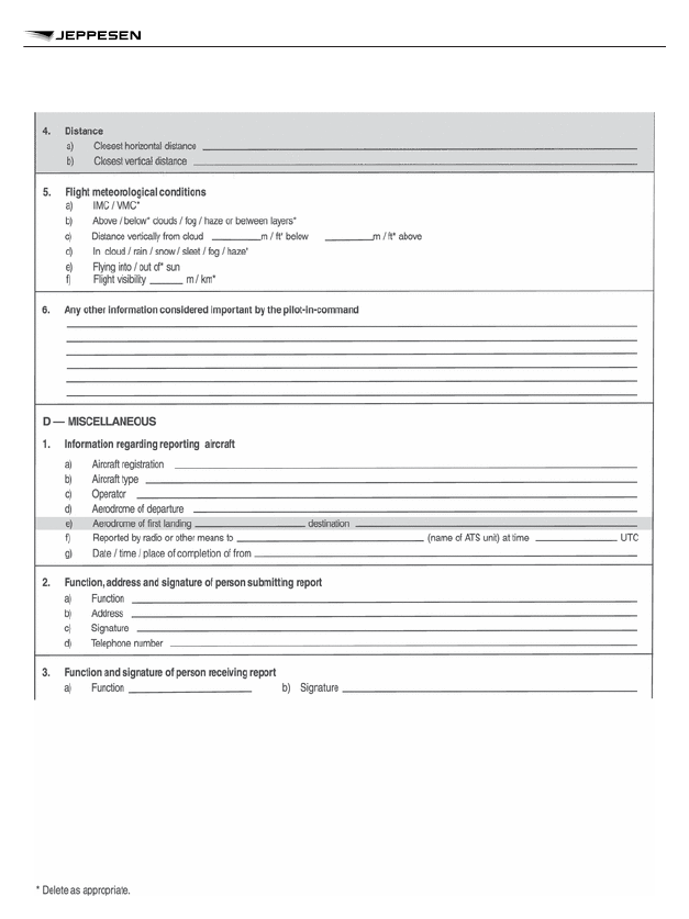
AIR TRAFFIC MANAGEMENT (DOC 4444) - APPENDIX 4 - AIR TRAFFIC INCIDENT REPORT

INSTRUCTIONS FOR THE COMPLETION OF THE AIR

TRAFFIC INCIDENT REPORT FORM

Item


A

Aircraft identification of the aircraft filing the report.

B

An AIRPROX report should be filed immediately by radio.

2

INTERNATIONAL CIVIL AVIATION ORGANIZATION -

AIR TRAFFIC MANAGEMENT

1314

AIR TRAFFIC MANAGEMENT (DOC 4444) - APPENDIX 4 - AIR TRAFFIC INCIDENT REPORT

C1

Date/time UTC and position in bearing and distance from a navigation aid or in
LAT/LONG.

C2

Information regarding aircraft filing the report, tick as necessary.

C2 c)

E.g, FL 350/1013 hPa or 2,500 ft/QNH 1007 hPa or 1,200 ft/QFE 998 hPa.

C3

Information regarding the other aircraft involved.

C4

Passing distance — state units used.

C6

Attach additional papers as required. The diagrams may be used to show air-
craft’s positions.

D1 f)

State name of ATS unit and date/time in UTC.

D1 g)

Date and time in UTC and place of completion of form.

E2

Include details of ATS unit such as service provided, radiotelephony frequency,
SSR codes assigned and altimeter setting. Use diagram to show the aircraft’s
position and attach additional papers as required.

INTERNATIONAL CIVIL AVIATION ORGANIZATION -

AIR TRAFFIC MANAGEMENT

1315

AIR TRAFFIC MANAGEMENT (DOC 4444) - APPENDIX 4 - AIR TRAFFIC INCIDENT REPORT

Air Traffic Control

International Civil Aviation

Organization - Aeronautical

Telecommunications - Annex 10

Extracted from ICAO ANNEX 10 (Vol. II) Seventh Edition — AERONAUTICAL TELECOMMU-
NICATIONS.

AERONAUTICAL MOBILE SERVICE — VOICE

COMMUNICATIONS

RADIOTELEPHONY PROCEDURES

General

Language to be Used

5.2.1.2.1   The air-ground radiotelephony communications shall be conducted in the language
normally used by the station on the ground or in the English language.
NOTE 1: The language normally used by the station on the ground may not necessarily be the
language of the State in which it is located. A common language may be agreed upon regionally
as a requirement for stations on the ground in that region.
NOTE 2: The level of language proficiency required for aeronautical radiotelephony communica-
tions is specified in the Appendix to Annex 1.
5.2.1.2.2   The English language shall be available, on request from any aircraft station, at all
stations on the ground serving designated airports and routes used by international air services.
5.2.1.2.3  The languages available at a given station on the ground shall form part of the Aero-
nautical Information Publications and other published aeronautical information concerning such
facilities.

Transmission of Numbers in Radiotelephony

TRANSMISSION OF NUMBERS

5.2.1.4.1.1  All numbers, except as prescribed in 5.2.1.4.1.2 to 5.2.1.4.1.6, shall be transmitted
by pronouncing each digit separately.
5.2.1.4.1.2  Flight levels shall be transmitted by pronouncing each digit separately except for the
case of flight levels in whole hundreds, which shall be transmitted by pronouncing the digit of the
whole hundred followed by the word HUNDRED.
NOTE: The following examples illustrate the application of this procedure (see 5.2.1.4.3.1 for pro-
nunciation).

flight levels

transmitted as


FL180


flight level 

one eight zero


FL200


flight level 

two hundred

5.2.1.4.1.3  The altimeter setting shall be transmitted by pronouncing each digit separately
except for the case of a setting of 1000 hPa which shall be transmitted as ONE THOUSAND.

5

5.2

5.2.1

5.2.1.2

5.2.1.4

5.2.1.4.1

INTERNATIONAL CIVIL AVIATION ORGANIZATION -
AERONAUTICAL TELECOMMUNICATIONS - ANNEX

10

1317

AERONAUTICAL TELECOMMUNICATIONS

NOTE: The following examples illustrate the application of this procedure (see 5.2.1.4.3.1 for pro-
nunciation).

altimeter setting

transmitted as


1009


QNH 

one zero zero nine


1000


QNH 

one thousand


993


QNH 

nine nine three

5.2.1.4.1.4  All numbers used in the transmission of transponder codes shall be transmitted by
pronouncing each digit separately except that, when the transponder codes contain whole thou-
sands only, the information shall be transmitted by pronouncing the digit in the number of thou-
sands followed by the word THOUSAND.
NOTE: The following examples illustrate the application of this procedure (see 5.2.1.4.3.1 for pro-
nunciation).

transponder codes

transmitted as


2400


squawk 

two four zero zero


1000


squawk 

one thousand


2000


squawk 

two thousand

5.2.1.4.1.5  All numbers used in the transmission of altitude, cloud height, visibility and runway
visual range (RVR), which contain whole hundreds and whole thousands, shall be transmitted by
pronouncing each digit in the number of hundreds or thousands followed by the word HUNDRED
or THOUSAND as appropriate. Combinations of thousands and whole hundreds shall be transmit-
ted by pronouncing each digit in the number of thousands followed by the word THOUSAND fol-
lowed by the number of hundreds followed by the word HUNDRED.
NOTE: The following examples illustrate the application of this procedure (see 5.2.1.4.3.1 for pro-
nunciation.

altitude

transmitted as


800


eight hundred


3400


three thousand four hundred


12000


one two thousand

cloud height

transmitted as


2200


two thousand two hundred


4300


four thousand three hundred

visibility

transmitted as

INTERNATIONAL CIVIL AVIATION ORGANIZATION -
AERONAUTICAL TELECOMMUNICATIONS - ANNEX

10

1318

AERONAUTICAL TELECOMMUNICATIONS


1000


visibility 

one thousand


700


visibility 

seven hundred

runway visual range

transmitted as


600


RVR 

six hundred


1700


RVR 

one thousand seven hundred

5.2.1.4.1.6  When providing information regarding relative bearing to an object or to conflicting
traffic in terms of the 12-hour clock, the information shall be given pronouncing the double digits
as TEN, ELEVEN, or TWELVE [O’CLOCK].
5.2.1.4.1.7  Numbers containing a decimal point shall be transmitted as prescribed in 5.2.1.4.1.1,
with the decimal point in appropriate sequence being indicated by the word DECIMAL.
NOTE: The following examples illustrate the application of this procedure.

Number

Transmitted as

100.3

ONE ZERO ZERO DECIMAL THREE

38143.9

THREE EIGHT ONE FOUR THREE DECIMAL NINE

NOTE: For identification of VHF frequencies the number of digits after the decimal point are deter-
mined on the basis of channel spacing (5.2.1.7.3.4.3 refers to frequencies separated by 25 kHz,
5.2.1.7.3.4.4 refers to frequencies separated by 8.33 kHz.
5.2.1.4.1.8  PANS — When transmitting time, only the minutes of the hour should normally be
required. Each digit should be pronounced separately. However, the hour should be included
when any possibility of confusion is likely to result.
NOTE: The following examples illustrate the application of this procedure when applying the pro-
visions of 5.2.1.2.2.

Time

Statement

0920 (9:20 A.M.)

TOO ZE-RO or
ZE-RO NIN-er TOO ZERO

1643 (4:43 P.M.)

FOW-er TREE or
WUN SIX FOW-er TREE

INTERNATIONAL CIVIL AVIATION ORGANIZATION -
AERONAUTICAL TELECOMMUNICATIONS - ANNEX

10

1319

AERONAUTICAL TELECOMMUNICATIONS

Calling

RADIOTELEPHONY PROCEDURES

Indication of Transmitting Frequency

5.2.1.7.3.4.3  PANS — Except as specified in 5.2.1.7.3.4.4 all six digits of the numerical designa-
tor should be used to identify the transmitting channel in VHF radiotelephony communications,
except in the case of both the fifth and sixth digits being zeros, in which case only the first four
digits should be used.
NOTE 1: The following examples illustrate the application of the procedure in 5.2.1.7.3.4.3:

Channel

Transmitted as

118.000

ONE ONE EIGHT DECIMAL ZERO

118.005

ONE ONE EIGHT DECIMAL ZERO ZERO FIVE

118.010

ONE ONE EIGHT DECIMAL ZERO ONE ZERO

118.025

ONE ONE EIGHT DECIMAL ZERO TWO FIVE

118.050

ONE ONE EIGHT DECIMAL ZERO FIVE ZERO

118.100

ONE ONE EIGHT DECIMAL ONE

NOTE 2: Caution must be exercised with respect to the indication of transmitting channels in VHF
radiotelephony communications when all six digits of the numerical designator are used in air-
space where communication channels are separated by 25 kHz, because on aircraft installations
with a channel separation capability of 25 kHz or more, it is only possible to select the first five
digits of the numerical designator on the radio management panel.
NOTE 3: The numerical designator corresponds to the channel identification in Annex 10, Volume
V, Table 4-1 (not published herein).
5.2.1.7.3.4.4  PANS — In airspace where all VHF voice communications channels are separated
by 25 kHz or more and the use of six digits as in 5.2.1.7.3.4.3 is not substantiated by the opera-
tional requirement determined by the appropriate authorities, the first five digits of the numerical
designator should be used, except in the case of both the fifth and sixth digits being zeros, in
which case only the first four digits should be used.
NOTE 1: The following examples illustrate the application of the procedure in 5.2.1.7.3.4.4 and
the associated settings of the aircraft radio management panel for communication equipment with
channel separation capabilities of 25 kHz and 8.33/25 kHz.

Channel

Transmitted as

Radio management panel setting for

communication equipment with


25 kHz (5 digits)

8.33/25 kHz (6 dig-

its)

5.2.1.7

5.2.1.7.3

5.2.1.7.3.4

INTERNATIONAL CIVIL AVIATION ORGANIZATION -
AERONAUTICAL TELECOMMUNICATIONS - ANNEX

10

1320

AERONAUTICAL TELECOMMUNICATIONS

118.000

ONE ONE EIGHT DECIMAL
ZERO

118.00

118.000

118.025

ONE ONE EIGHT DECIMAL
ZERO TWO

118.02

118.025

118.050

ONE ONE EIGHT DECIMAL
ZERO FIVE

118.05

118.050

118.075

ONE ONE EIGHT DECIMAL
ZERO SEVEN

118.07

118.075

118.100

ONE ONE EIGHT DECIMAL
ONE

118.10

118.100

NOTE 2: Caution must be exercised with respect to the indication of transmitting channels in VHF
radiotelephony communications when five digits of the numerical designator are used in airspace
where aircraft are also operated with channel separation capabilities of 8.33/25 kHz. On aircraft
installations with a channel separation capability of 8.33 kHz and more, it is possible to select six
digits on the radio management panel. It should therefore be ensured that the fifth and sixth digits
are set to 25 kHz channels (see Note 1).
NOTE 3: The numerical designator corresponds to the channel identification in Annex 10, Volume
V, Table 4-1 (not published herein).

INTERNATIONAL CIVIL AVIATION ORGANIZATION -
AERONAUTICAL TELECOMMUNICATIONS - ANNEX

10

1321

AERONAUTICAL TELECOMMUNICATIONS

Air Traffic Control

Air Traffic Management - General

Data

INTRODUCTION

1.1  The term “Mach number technique” is used to describe the technique of clearing turbo-jet
aircraft operating along the same route to maintain specified Mach numbers in order to maintain
adequate longitudinal separation between successive aircraft at, or climbing or descending to, the
same level.

OBJECTIVES

2.1  The principal objectives of the use of the Mach number technique are:

a. to ensure continued longitudinal separation between successive aircraft on long route seg-

ments with a minimum of Air Traffic Control (ATC) intervention;

b. to obtain improved utilization of such routes, thus contributing to the economy of flight opera-

tions of traffic concerned.

2.2  To achieve these objectives the speeds of aircraft operating along the same track at the
same level or climbing or descending to operate at the same level are stabilized. This stability
permits reasonably accurate projections of the expected longitudinal separation between aircraft
to points well beyond the point where separation is first confirmed, which reduces the need for
frequent ATC intervention.
2.3  Practical experience in the North Atlantic (NAT) region has confirmed the assumptions made
above. It has been found that successive aircraft operating along the same track at the same level
and aircraft climbing or descending to operate at the same level as another aircraft and maintain-
ing the same Mach number also maintain a reasonably constant time interval between each
other, when checked by position reports over the same point. This is due to the fact that the air-
craft concerned are normally subject to approximately the same wind and temperature conditions.
Minor variations in speed which might temporarily increase or decrease the spacing between air-
craft tend to be neutralized over prolonged periods of flight.

PREREQUISITES

AREA OF APPLICATION

3.1.1  The application of the Mach number technique is particularly suitable for areas where the
environment is such that position reporting and ATC intervention with individual flights can, at
times, be subject to delay. In addition, the following represent typical characteristics of the route
structure and environment which make the use of a given area suitable for the application of the
Mach number technique:

a. aircraft in the area generally follow the same or diverging tracks until they are provided with

other forms of separation;

b. operations conducted in the area comprise a significantly large phase of stable flight (e.g.,

not less than one hour) and the aircraft concerned have normally reached an operationally
suitable level when entering the area.

1

2

3

3.1

AIR TRAFFIC MANAGEMENT - GENERAL DATA

1323

MACH NUMBER TECHNIQUE

AIRCRAFT INSTRUMENTATION

3.2.1  The use of the Mach number technique in a given area is based on the assumption that
the relevant instruments used by aircraft to which this technique is applied have been calibrated in
accordance with applicable airworthiness practices. Therefore, both States of Registry and opera-
tors concerned should take the necessary measures to ensure continued compliance with this
prerequisite.

FLIGHT PROGRESS INFORMATION FOR ATC

3.3.1  ATC units using the Mach number technique must have at their disposal the latest forecast
upper wind information, or position information obtained from previous aircraft. Such information
is necessary in order to permit ATC to prepare (either manually or by means of a computer) flight
progress strips showing calculated estimated times over significant points up to and including the
exit point from the area wherein the technique is applied in order to confirm that the required lon-
gitudinal separation will exist at the exit point.

ADHERENCE TO ASSIGNED MACH NUMBER

3.4.1  Unless otherwise advised by the pilot concerned, ATC will assume that the last assigned
Mach number will be maintained both in cruise and in any cleared step-climbs or step-descents
made in the course of the flight.

GENERAL PROCEDURES

4.1  Application of the Mach number technique should always be based on the true Mach
number.
The airspeeds and altitudes planned to be used should be specified in flight plan as follows:

a. True airspeed and altitude immediately preceding the initial domestic portion of the route of

flight.

b. True Mach number and altitude immediately preceding oceanic portion of the route of flight.

Example of field 15 of ICAO Flight Plan: 0450F340 MOLOKAI2 CLUTS/M084F340 R465 CLUKK
SFO.
4.2  The ATC clearance must include the assigned Mach number which is to be maintained. It is
therefore necessary that information on the desired Mach number be included in the flight plans
by pilots intending to operate along routes in the area concerned.
4.3  ATC has a requirement to calculate estimated times at which aircraft will pass significant
points along their track. These calculations are necessary both for the provision of longitudinal
separation between aircraft on crossing tracks, and for coordination with adjacent ATC units.
Therefore ATC must be provided with necessary data to do this.
4.4  It is very important that the estimates for the entry point to the area provided by pilots are as
accurate as possible since they form the basis for the advance planning of longitudinal separation
between aircraft.
4.5  The prescribed longitudinal separation between successive aircraft flying at the same level
must be provided over the entry point and on a particular track or tracks, or exist when climb or

3.2

3.3

3.4

4

AIR TRAFFIC MANAGEMENT - GENERAL DATA

1324

MACH NUMBER TECHNIQUE

descent to the level of another aircraft is accomplished into the area concerned. Standard longitu-
dinal separation is 15 minutes.
4.6  Thereafter, provided that aircraft maintain their last assigned Mach numbers, intervention by
ATC for the portion of flight where the Mach number technique is used, should normally only be
necessary if an aircraft, for some reason, is obliged to change its number or if there is conflicting
traffic on crossing tracks or a flight level change is intended.
4.7  The Mach number technique requires that pilots strictly adhere to the following procedures:

a. aircraft must strictly adhere to the last assigned Mach number;
b. if essential to make an immediate temporary change in Mach number (e.g., due to turbu-

lence) the appropriate ATC unit should be notified as soon as possible of that change;

c. when required by the appropriate ATC unit, the current true Mach number should be inclu-

ded in routine position reports.

4.8  Due account must be taken of problems which may be caused at entry and exit points if the
longitudinal separation minima used in adjacent airspace differ from those used in the area where
the Mach number technique is used.
4.9  For a list of ATS routes and areas where the Mach number technique is used, see the indi-
vidual ATC “State Page” under the heading Mach Number Technique (MNT).

AIR TRAFFIC MANAGEMENT - GENERAL DATA

1325

MACH NUMBER TECHNIQUE

Air Traffic Control

Performance Based Communication

and Surveillance (PBCS) - Doc 9869

PERFORMANCE BASED COMMUNICATION AND SURVEILLANCE

(PBCS)

BASIC INFORMATION

Performance Based Communication (PBC) and Performance Based Surveillance (PBS) refers to
communication and surveillance based on performance specifications applied to the provision of
air traffic services. The standards and procedures for an air traffic management (ATM) operation
that are predicated on communication and surveillance capabilities, such as the application of
reduced separation minima, must refer to the appropriate Required Communication Performance
(RCP) and Required Surveillance Performance (RSP) specification.
The RCP and RSP specifications are a set of requirements for air traffic service provision and
associated ground equipment, aircraft capability and operations needed to support performance
based communication and surveillance.

PERFORMANCE BASED COMMUNICATION AND

SURVEILLANCE (PBCS) - DOC 9869

1327

PERFORMANCE BASED COMMUNICATION AND SURVEILLANCE (PBCS) - DOC 9869

Operational context of communication and surveillance capability and performance

RCP SPECIFICATIONS

General
The operational requirements of an RCP specification apply to the controller's communication and
intervention capability. These requirements also define parameter values for operational (end-to-
end) RCP transaction times, RCP continuity, RCP availability and RCP integrity, as well as their
allocated values (e.g. required communication monitored performance (RCMP), required commu-
nication technical performance (RCTP) and, when applicable, human performance). An underly-
ing assumption in the application of RCP is the compatibility and interoperability of the supporting
system components, in accordance with interoperability standards.

PERFORMANCE BASED COMMUNICATION AND

SURVEILLANCE (PBCS) - DOC 9869

1328

PERFORMANCE BASED COMMUNICATION AND SURVEILLANCE (PBCS) - DOC 9869

An RCP specification is identified by a designator (e.g. RCP 240) to simplify the RCP designator
naming convention and to make the RCP transaction time readily apparent to airspace planners,
aircraft manufacturers and operators. The designator represents the maximum communication
transaction time after which the initiator should revert to an alternative procedure (or RCP expira-
tion time).

RCP type parameters
The set of requirements for an RCP specification are based on the following parameters:

– RCP transaction time - The maximum time for the completion of the operational communication

transaction after which the initiator should revert to an alternative procedure.

– RCP continuity - The minimum proportion of operational communication transactions to be

completed within the specified RCP transaction time, given that the service was available at the
start of the transaction.

– RCP availability - The required probability that an operational communication transaction can

be initiated.

– RCP integrity - The required probability that an operational communication transaction is com-

pleted with no undetected errors.

Currently, the number of specifications is limited to two (RCP 240 and RCP 400) in airspace
where procedural separation is applied. Other RCP specifications may be added, pending the
introduction of new ATM operations or the use of new communication technologies.

RCP Specifica-

tion

RCP Transaction

Time (seconds)

RCP Continuity

(probability)

RCP Availability

(probability)

RCP integrity

(acceptable

rate / Flight

Hours)

RCP 240

240

0.999

0.999

10

-5

RCP 400

400

0.999

0.999

10

-5

RCP 240 may be applied to maintain the performance for normal means of communication, which
supports controller intervention capability in procedurally controlled airspace, where the separa-
tion minimum applied is predicated on communication performance.
RCP 400 may be applied to maintain the performance for emerging technology (e.g. satellite
voice) used to provide normal means of communication supporting controller intervention capabil-
ity in procedurally controlled airspace, where the separation minimum applied is based on position
reporting at compulsory reporting points. RCP 400 may also be applied to maintain the perform-
ance required for emerging technologies used to provide alternative means of communication,
that may be required in combination with the normal means of communication, to which RCP 240
is applied.

PERFORMANCE BASED COMMUNICATION AND

SURVEILLANCE (PBCS) - DOC 9869

1329

PERFORMANCE BASED COMMUNICATION AND SURVEILLANCE (PBCS) - DOC 9869

RCP transaction time and allocations
There may be multiple operational communication transactions that support an ATM operation.
These transactions are therefore assessed to determine which is the most stringent. The value for
the RCP transaction time is based on the time needed to complete the most stringent transaction
for controller intervention.
The assessment would take into consideration the time needed to safely execute the contingency
procedure and can include simulations, demonstrations, operational trials and analysis of empiri-
cal data applicable to the RCP communication transaction times for the ATM operation.
For separation assurance, the RCP transaction time can be determined by collision risk model-
ling. Collision risk modelling considers the RCP transaction times in the communications and con-
troller intervention buffer supporting separation assurance. Figure “Operational context of commu-
nication and surveillance capability and performance” illustrates the operational communication
transaction in the context of communications and controller intervention buffer.

RSP SPECIFICATIONS

General
The operational requirements of an RSP specification apply to the surveillance services and
define parameter values for surveillance data transit times, RSP continuity, RSP availability and
RSP integrity, as well as allocated values (e.g. required surveillance monitored performance
(RSMP), required surveillance technical performance (RSTP) and, when applicable, human per-
formance). When applying RSP, it is assumed that that the supporting system components are
compatible and interoperable, in accordance with interoperability standards.
An RSP specification is identified by a designator (e.g. RSP 180) in order to simplify the designa-
tor naming convention and to make the required surveillance data delivery time readily apparent
to airspace planners, aircraft manufacturers and operators. The designator represents the value
for the surveillance data delivery time when the surveillance data delivery is considered overdue.

RSP type parameters
The set of requirements for an RSP specification are based on the following parameters:

– RSP surveillance data transit time - Maximum time for the reception of the surveillance data

after which the controller should revert to an alternative procedure.

– RSP continuity - The minimum proportion of surveillance data delivery to be completed within

the specified RSP surveillance data delivery time, given that the service was available at the
start of the delivery.

– RSP availability - The required probability that surveillance data can be provided.
– RSP integrity - The required probability that surveillance data delivery is completed with no

‘undetected’ errors.

Currently, the number of specifications is limited to two (RSP 180 and RSP 400) in airspace
where procedural separation applies. Other RSP specifications may be added, pending the intro-
duction of new ATM operations or the use of new surveillance technologies.

PERFORMANCE BASED COMMUNICATION AND

SURVEILLANCE (PBCS) - DOC 9869

1330

PERFORMANCE BASED COMMUNICATION AND SURVEILLANCE (PBCS) - DOC 9869

RSP Specifica-

tion

RSP Delivery

Time (seconds)

RSP Continuity

(probability)

RSP Availability

(probability)

RSP integrity

(acceptable

rate / Flight

Hours)

RSP 180

180

0.999

0.999

FOM=Navigation

Specification

Time at Position

Accuracy +/-1

Sec

Data integrity

(malfunction) =

10

-5

RSP 400

400

0.999

0.999

FOM=Navigation

Specification

Time at Position

Accuracy +/-30

Sec

Data integrity

(malfunction) =

10

-5

RSP 180 may be applied to maintain the performance for normal means of surveillance, which
supports controller intervention capability in procedurally controlled airspace, where the separa-
tion minimum applied is predicated on surveillance performance.
RSP 400 may be applied to maintain the performance for emerging technology (e.g. satellite
voice) used to provide normal means of surveillance supporting controller intervention capability
in procedurally controlled airspace, where the separation minimum being applied is based on
position reporting at compulsory reporting points. RSP 400 might also be applied to maintain the
performance required for emerging technologies used to provide alternative means of surveil-
lance, that may be required in combination with the normal means of surveillance, to which RSP
180 is applied.

RSP data delivery time and allocations
The value for the RSP data delivery time is based on the time when the surveillance data delivery
is considered overdue.
The assessment would take into consideration the time needed to safely execute the contingency
procedure and can include an analysis of empirical data applicable to the RSP data delivery times
for the ATM operation.
For separation assurance, the RSP data delivery can be determined by collision risk modelling.
This method considers the RSP delivery times in the surveillance data delivery supporting separa-

PERFORMANCE BASED COMMUNICATION AND

SURVEILLANCE (PBCS) - DOC 9869

1331

PERFORMANCE BASED COMMUNICATION AND SURVEILLANCE (PBCS) - DOC 9869

tion assurance. Figure “Operational context of communication and surveillance capability and per-
formance” illustrates the surveillance data delivery in the context of surveillance capabilities.

COMPLYING WITH AN RCP/RSP SPECIFICATION

Aircraft operator eligibility
The aircraft operator should meet the requirements established by the State of the Operator or
State of Registry to be eligible for PBCS operations.
The aircraft operator should consider the guidance in this section as it applies to flight crew train-
ing and qualification, the aircraft system, MEL, continued airworthiness, user modifiable software
and Communication Service Provider (CSP) service agreements.
The aircraft operator should ensure that procedures are established and the flight crews and other
personnel (e.g. aircraft maintenance, flight operations officer/flight dispatcher) are trained and
qualified for PBCS operations. The flight crew procedures and training should include normal
operations, as well as those associated with alerts provided by the aircraft system to indicate fail-
ures when the aircraft is no longer capable of meeting the RCP/RSP specification prescribed for
the associated ATM operations.
The aircraft operator should ensure that contracted services, such as those with CSPs, are bound
by contractual arrangements stipulating the RCP/RSP allocations, including any monitoring or
recording requirements.
The aircraft operator should ensure that contractual arrangements include a provision for the CSP
to notify the appropriate ATS units for the route system of the aircraft operator in case failure con-
ditions impact PBCS operations.
The aircraft operator should ensure that the aircraft system has been approved for the intended
use, in accordance with the appropriate RCP/RSP specification(s) and guidelines.
The aircraft operator should ensure that the aircraft system is properly maintained, including con-
figuring user-modifiable software, such as those used to manage communication media and rout-
ing policies, to meet the appropriate RCP/RSP specification(s).
The aircraft operator should participate in local and regional PBCS monitoring programmes, which
are applicable to the aircraft operator's route system, and should provide the following information
to the appropriate PBCS monitoring entities specified in AlPs (or equivalent publications):

a. operator name;
b. operator contact details; and

c. other coordination information.

The aircraft operator should advise the appropriate PBCS monitoring entities of any changes to
the information listed above.
The aircraft operator should establish procedures to report problems, identified either by the flight
crew or other personnel, to the appropriate PBCS monitoring entities associated with the route of
flight on which the problem occurred.

PERFORMANCE BASED COMMUNICATION AND

SURVEILLANCE (PBCS) - DOC 9869

1332

PERFORMANCE BASED COMMUNICATION AND SURVEILLANCE (PBCS) - DOC 9869

The aircraft operator should ensure procedures are established for the timely disclosure and
delivery of operational data, including data from its CSPs/SSPs, to the appropriate PBCS monitor-
ing entity when requested for the purposes of investigating a reported problem.

FLIGHT PLAN REQUIREMENTS

When filing RCP/RSP capabilities, the aircraft operator should ensure that the planned use of
associated communication and surveillance capabilities for the flight will be in accordance with
regulations, policies and procedures in control areas for the flight, as published by the applicable
States in their AlPs (or equivalent publications).
NOTE: RCP/RSP capabilities are inserted only when the descriptors J2 through J7 for CPDLC,
M1 through M3 for SATVOICE, and/or D1 for ADS-C, are also inserted. While RCP/RSP capabil-
ity denotes performance, the descriptors J2 through J7, M1 through M3 and D1 in Item 10 (see
Table below) denote the interoperability for the aircraft equipment.
In Item 10 of the flight plan, the aircraft operator should insert one or more descriptors, as appro-
priate, listed in Table below, to identify an aircraft's RCP capability:

Descriptors for RCP capability in flight plan - Item 10

Item 10a - Radio communication, navigation

and approach aid equipment and capabili-

ties

Descriptor

CPDLC RCP 400

P1

CPDLC RCP 240

P2

SATVOICE RCP 400

P3

In Item 18 of the flight plan, the aircraft operator should file the RSP capability by inserting the
indicator SUR/ followed by the appropriate designator, with no spaces, for the RSP specification
(e.g. RSP 400 or RSP 180).

PERFORMANCE BASED COMMUNICATION AND

SURVEILLANCE (PBCS) - DOC 9869

1333

PERFORMANCE BASED COMMUNICATION AND SURVEILLANCE (PBCS) - DOC 9869

Air Traffic Control

Aerodrome Operating Minimums -

EASA Air Operations

General and Aeroplane Specific Material (2016)

1 GENERAL

On 5 October 2012 the Commission Regulation (EU) No 965/2012 and related documents were
published, laying down technical requirements and administrative procedures related to air opera-
tions pursuant to Regulation (EC) No 216/2008 of the European Parliament and of the Council.
The European Aviation Safety Agency (EASA) publishes Regulations on Air Operations with the
associated Decisions containing Acceptable Means of Compliance (AMC) and Guidance Material
(GM).
On JEPPESEN approach and aerodrome charts an inverse printed 

“Standard” label in the upper

left corner of the minimums band indicates that the minimums are derived according to the
requirements described in EASA Air Operations documents.
TERPS change 20 was harmonized with the EASA minimum tables for CAT I, APV and NPA
(CAT C and D aircraft only). Those procedures with the TERPS label are therefore EASA AIR
OPS compliant for CAT C and D aircraft operators.
The following explanation is an excerpt to summarize only the relevant parts of the EASA Air
Operations (EASA Air OPS) regarding the methods used to determine Aerodrome Operating Mini-
mums (Rules, AMC or GM). It is not intended to provide all the requirements of the EASA Air OPS
related documents.
The publication of EASA Air Operations landing and take-off minimums on Jeppesen charts does
not constitute authority for their use by every operator. Each individual operator is responsible for
validating that the appropriate approval has been obtained for their use.
In addition, the minimums are only considered applicable if:

– the required ground equipment for the intended procedure is operative; and
– the required aircraft systems for the type of approach are operative; and
– the required aircraft performance criteria are met; and
– the crew is qualified accordingly.

2 TERMINOLOGY

Acceptable Means of Compliance (AMC) — means non-binding standards adopted by the
Agency to illustrate means to establish compliance with Regulation (EC) No 216/2008 and its
Implementing Rules.
CAT.OP.MPA.xxx — Implementing rule (IR) from regulation for PART-CAT (Commercial Air
Transport Operations)
SPA.LVO.xxx — Implementing rule from regulation for PART-SPA (Specific Approvals)
AMC1 CAT.OP.MPA.115 — Acceptable Means of Compliance to the related IR CAT.OP.MPA.
115
GM1 CAT.OP.MPA.110 — Guidance Material to the related IR CAT.OP.MPA.110

AERODROME OPERATING MINIMUMS - EASA AIR

OPERATIONS

1335

AERODROME OPERATING MINIMA - EASA AIR OPERATIONS

3 OPERATORS RESPONSIBILITY

CAT.OP.MPA.110 Aerodrome operating minimums

a. An operator shall establish aerodrome operating minimums for each departure, destination

or alternate aerodrome planned to be used. These minimums shall not be lower than those
established for such aerodromes by the State in which the aerodrome is located, except
when specifically approved by that State. Any increment specified by the competent authority
shall be added to the minimums.

b. The use of a head-up display (HUD), head-up guidance landing system (HUDLS) or

enhanced vision system (EVS) may allow operations with lower visibilities than the estab-
lished aerodrome operating minimums if approved in accordance with SPA.LVO.

c. When establishing aerodrome operating minimums, the operator shall take the following into

account:

1. the type, performance and handling characteristics of the aircraft;
2. the composition, competence and experience of the flight crew;
3. the dimensions and characteristics of the runways/final approach and take-off areas

(FATO) that may be selected for use;

4. the adequacy and performance of the available visual and non-visual ground aids;
5. the equipment available on the aircraft for navigation and/or control of the flight path

during the take-off, the approach, the flare, the landing, the roll-out and the missed
approach;

6. for the determination of obstacle clearance, the obstacles in the approach, missed

approach and the climb-out areas necessary for the execution of the contingency proce-
dures;

7. the obstacle clearance altitude/height for the instrument approach procedure;
8. the means to determine and report meteorological conditions; and
9. the flight technique to be used during the final approach.

d. The operator shall specify the method of determining aerodrome operating minimums in the

operations manual.

e. The minimums for a specific approach and landing procedure shall only be used if all the fol-

lowing conditions are met:

1. the ground equipment shown on the chart required for the intended procedure is opera-

tive;

2. the aircraft systems required for the type of approach are operative;
3. the required aircraft performance criteria are met; and
4. the crew is appropriately qualified.

GM1 CAT.OP.MPA.110(a) Aerodrome operating minimums

AERODROME OPERATING MINIMUMS - EASA AIR

OPERATIONS

1336

AERODROME OPERATING MINIMA - EASA AIR OPERATIONS

INCREMENTS SPECIFIED BY THE COMPETENT AUTHORITY
Additional increments to the published minimums may be specified by the competent authority to
take into account certain operations, such as downwind approaches and single-pilot operations.

4 LOW VISIBILITY OPERATIONS

SPA.LVO.100 Low visibility operations
The operator shall only conduct the following low visibility operations (LVO) when approved by the
competent authority:

a. low visibility take-off (LVTO) operation;
b. lower than standard category I (LTS CAT I) operation;

c. standard category II (Cat II) operation;

d. other than standard category II (OTS CAT II) operation;
e. standard category III (CAT III) operation;

f. approach operation utilising enhanced vision systems (EVS) for which an operational credit

is applied to reduce the runway visual range (RVR) minimums by no more than one third of
the published RVR.

SPA.LVO.115 Aerodrome related requirements

a. The operator shall not use an aerodrome for LVOs below a visibility of 800m unless:

1. the aerodrome has been approved for such operations by the State of the aerodrome;

and

2. low visibility procedures (LVP) have been established.

b. If the operator selects an aerodrome where the term LVP is not used, the operator shall

ensure that there are equivalent procedures that adhere to the requirements of LVP at the
aerodrome. This situation shall be clearly noted in the operations manual or procedures
manual including guidance to the flight crew on how to determine that the equivalent LVP are
in effect.

5 APPROACH FLIGHT TECHNIQUE

CAT.OP.MPA.115 Approach flight technique - aeroplanes

a. All approaches shall be flown as stabilised approaches unless otherwise approved by the

competent authority for a particular approach to a particular runway.

b. Non-precision approaches:

1. The continuous descent final approach (CDFA) technique shall be used for all non-pre-

cision approaches.

2. Nothwithstanding 1., another approach flight technique may be used for a particular

approach/runway combination if approved by the competent authority. In such cases,
the applicable minimum runway visual range (RVR):

AERODROME OPERATING MINIMUMS - EASA AIR

OPERATIONS

1337

AERODROME OPERATING MINIMA - EASA AIR OPERATIONS

i. shall be increased by 200m for category A and B aeroplanes and by 400m for cat-

egory C and D aeroplanes; or

ii. for aerodromes where there is a public interest to maintain current operations and

the CDFA technique cannot be applied, shall be established and regularly
reviewed by the competent authority taking into account the operator’s experience,
training programme and flight crew qualification.

AMC1 CAT.OP.MPA.115 Approach flight technique - aeroplanes
CONTINUOUS DESCENT FINAL APPROACH (CDFA)

a. Flight techniques:

1. The CDFA technique should ensure that an approach can be flown on the desired verti-

cal path and track in a stabilized manner, without significant vertical path changes
during the final approach segment descent to the runway. This technique applies to an
approach with no vertical guidance and controls the descent path until the DA/H. This
descent path can be either:

i. a recommended descent rate, based on estimated ground speed;

ii. a descent path depicted on the approach chart; or

iii. a descent path coded in the flight management system in accordance with the

approach chart descent path.

2. The operator should either provide charts which depict the appropriate cross check alti-

tudes/heights with the corresponding appropriate range information, or such information
should be calculated and provided to the flight crew in an appropriate and usable
format. Generally, the MAPt is published on the chart.

4. The required descent path should be flown to the DA/H, observing any stepdown cross-

ing altitudes if applicable.

5. This DA/H should take into account any add-on to the published minimums as identified

by the operator’s management system and should be specified in the OM (aerodrome
operating minimums).

7. The operator should establish a procedure to ensure that an appropriate callout is made

when the aeroplane is approaching DA/H. If the required visual references are not
established at DA/H, the missed approach procedure is to be executed promptly.

9. The missed approach should be initiated no later than reaching the MAPt or at the

DA/H, whichever comes first. The lateral part of the missed approach should be flown
via the MAPt unless otherwise stated on the approach chart.

AMC2 CAT.OP.MPA.115 Approach flight technique - aeroplanes
NPA OPERATIONS WITHOUT APPLYING THE CDFA TECHNIQUE

a. In case the CDFA technique is not used, the approach should be flown to an altitude/height

at or above the MDA/H where a level flight segment at or above MDA/H may be flown to the
MAPt.

AERODROME OPERATING MINIMUMS - EASA AIR

OPERATIONS

1338

AERODROME OPERATING MINIMA - EASA AIR OPERATIONS

e. The procedures that are flown with level flight at/or above MDA/H should be listed in the OM.

6 MET VISIBILITY/RVR/CMV

CAT.OP.MPA.305 - Commencement and continuation of approach

c. Where the RVR is not available, RVR values may be derived by converting the reported visi-

bility.

AMC10 CAT.OP.MPA.110 Aerodrome operating minimums
CONVERSION OF REPORTED METEOROLOGICAL VISIBILITY TO RVR

a. A conversion from meteorological visibility to RVR/CMV should not be used:

1. when reported RVR is available;
2. for calculating take-off minimums; and
3. for any RVR minimums less than 800m.

b. If the RVR is reported as being above the maximum value assessed by the aerodrome oper-

ator, e.g. “RVR more than 1500m”, it should not be considered as a reported value for a.1.

c. When converting meteorological visibility to RVR in circumstances other than those in a., the

conversion factors specified in Table 8 should be used.

AMC10 CAT.OP.MPA.110 Table 8 Conversion of reported MET VIS to CMV

Light Elements in Operation

CMV = Reported Meteorological Visibility x Conversion

Factor

Day

Night

High intensity approach and
runway lights

1.5

2.0

Any type of light installation
other than above

1.0

1.5

No lights

1.0

Not applicable

7 APPROACH LIGHT SYSTEMS

AMC5 CAT.OP.MPA.110 Aerodrome operating minimums
APPROACH LIGHTING SYSTEMS

AERODROME OPERATING MINIMUMS - EASA AIR

OPERATIONS

1339

AERODROME OPERATING MINIMA - EASA AIR OPERATIONS

AMC5 CAT.OP.MPA.110 Table 4 Approach Lighting Systems

Class of Lighting Facilities

Length, Configuration and Intensity of Ap-

proach Lights

FALS

CAT I approach lighting system (HIALS 

720m) distance coded centerline, Barrette cen-
terline

IALS

Simple approach lighting system (HIALS
420-719m) single source, Barrette

BALS

Any other approach lighting system (HIALS or
MIALS or ALS 210-419m)

NALS

Any other approach lighting system (HIALS, MI-
ALS or ALS < 210m) or no approach lights

8 DETERMINATION OF AOM FOR TAKE-OFF

AMC1 CAT.OP.MPA.110 Aerodrome operating minimums
TAKE-OFF OPERATIONS - AEROPLANES

a. General

1. Take-off minimums should be expressed as visibility or runway visual range (RVR)

limits, taking into account all relevant factors for each aerodrome planned to be used
and aircraft characteristics. Where there is a specific need to see and avoid obstacles
on departure and/or for a forced landing, additional conditions, e.g. ceiling, should be
specified.

2. The commander should not commence take-off unless the weather conditions at the

aerodrome of departure are equal to or better than the applicable minimums for landing
at that aerodrome unless a weather-permissible take-off alternate aerodrome is availa-
ble.

3. When the reported meteorological visibility (VIS) is below that required for take-off and

RVR is not reported, a take-off should only be commenced if the commander can deter-
mine that the visibility along the take-off runway is equal to or better than the required
minimum.

4. When no reported meteorological visibility or RVR is available, a take-off should only be

commenced if the commander can determine that the visibility along the take-off runway
is equal to or better than the required minimum.

VISUAL REFERENCE

AMC1 CAT.OP.MPA.110 Aerodrome operating minimums
TAKE-OFF OPERATIONS - AEROPLANES

b. Visual Reference

AERODROME OPERATING MINIMUMS - EASA AIR

OPERATIONS

1340

AERODROME OPERATING MINIMA - EASA AIR OPERATIONS

1. The take-off minimums should be selected to ensure sufficient guidance to control the

aircraft in the event of both a rejected take-off in adverse circumstances and a contin-
ued take-off after failure of the critical engine.

2. For night operations, ground lights should be available to illuminate the runway and any

obstacles.

REQUIRED RVR/VIS

AMC1 CAT.OP.MPA.110 Aerodrome operating minimums
TAKE-OFF OPERATIONS - AEROPLANES

c. Required RVR/VIS - aeroplane

1. For multi-engined aeroplanes, with performance such that in the event of a critical

engine failure at any point during take-off the aeroplane can either stop or continue that
take-off to a height of 1500ft above the aerodrome while clearing obstacles by the
required margins, the take-off minimums specified by the operator should be expressed
as RVR/VIS values not lower than those specified in Table 1.A.

2. For multi-engined aeroplanes without the performance to comply with the conditions in

c.1. in the event of a critical engine failure, there may be a need to re-land immediately
and to see and avoid obstacles in the take-off area. Such aeroplanes may be operated
to the following take-off minimums provided they are able to comply with the applicable
obstacle clearance criteria, assuming engine failure at the height specified. The take-off
minimums specified by the operator should be based upon the height from which the
one-engine-inoperative (OEI) net take-off flight path can be constructed. The RVR mini-
mums used should not be lower than either of the values specified in Table 1.A or Table
2.A.

AMC1 CAT.OP.MPA.110 Table 1.A Take-off RVR/VIS - Aeroplanes (without an Approval for

Low Visibility Take-off)

Facilities

RVR/VIS

Day only

NIL

500m

Day

at least runway edge lights or
centerline marking

400m

Night

at least runway edge lights and
runway end lights or runway
centerline lights and runway
end lights

The reported RVR/VIS value representative of the initial part of the take-off run can be replaced
by the pilot assessment.
During day with Nil facilities: The pilot is able to continuously identify the take-off surface and
maintain directional control.

AERODROME OPERATING MINIMUMS - EASA AIR

OPERATIONS

1341

AERODROME OPERATING MINIMA - EASA AIR OPERATIONS

AMC1 CAT.OP.MPA.110 Table 2.A Take-off - AeroplanesAssumed Engine Failure Height

above the Runway versus RVR/VIS

Assumed Engine Failure Height above the

Take-off Runway

RVR/VIS

 50ft

400m (200m with LVTO approval)

51ft-100ft

400m (300m with LVTO approval)

101ft-150ft

400m

151ft-200ft

500m

201ft-300ft

1000m

More than 300ft

1500m

1500m is also applicable if no positive take-off flight path can be constructed.
The reported RVR/VIS value representative of the initial part of the take-off run can be replaced
by pilot assessment.
AMC1 SPA.LVO.100 Low visibility operations
LVTO OPERATIONS - AEROPLANES
For a low visibility take-off (LVTO) with an aeroplane the following provisions should apply:

a. for an LVTO with a runway visual range (RVR) below 400m the criteria specified in Table 1.A

below;

b. for an LVTO with an RVR below 150m but not less than 125m:

1. high intensity runway centerline lights spaced 15m or less apart and high intensity edge

lights spaced 60m or less apart that are in operation;

2. a 90m visual segment that is available from the flight crew compartment at the start of

the take-off run; and

3. the required RVR value is achieved for all of the relevant RVR reporting points;

c. for an LVTO with an RVR below 125m but not less than 75m:

1. runway protection and facilities equivalent to CAT III landing operations are available;

and

2. the aircraft is equipped with an approved lateral guidance system.

AMC1 SPA.LVO.100 Table 1.A LVTO - Aeroplanes

Facilities

RVR

Day: runway edge lights and runway centerline markings

300m

Night: runway edge lights and runway end lights or runway
centerline lights and runway end lights

AERODROME OPERATING MINIMUMS - EASA AIR

OPERATIONS

1342

AERODROME OPERATING MINIMA - EASA AIR OPERATIONS

AMC1 SPA.LVO.100 Table 1.A LVTO - Aeroplanes (continued)

Facilities

RVR

Runway edge lights and runway centerline lights

200m

Runway edge lights and runway centerline lights and rele-
vant RVR

TDZ, MID, rollout 150m

High intensity runway centerline lights spaced 15m or less
and high intensity edge lights spaced 60m or less are in op-
eration

TDZ, MID, rollout 125m

Runway protection and facilities equivalent to CAT III land-
ing operations are available 

and the aircraft is equipped ei-

ther with an approved lateral guidance system or an ap-
proved HUD/HUDLS for take-off

TDZ, MID, rollout 75m

The reported RVR value representative of the initial part of the take-off run can be replaced by
pilot assessment.
The RVR values are valid for multi-engined aeroplanes that in the event of an engine failure at
any point during take-off can either stop or continue the take-off to a height of 1500ft above the
aerodrome while clearing obstacles by the required margin.
The required RVR value to be achieved for all relevant RVRs.

9 DETERMINATION OF AOM FOR CIRCLING

AMC7 CAT.OP.MPA.110 Aerodrome operating minimums
CIRCLING OPERATIONS - AEROPLANES

a. Circling Minimums

The following standards should apply for establishing circling minimums for operations with
aeroplanes:

1. The MDH for circling operation should not be lower than the highest of:

i. the published circling OCH for the aeroplane category;

ii. the minimum circling height derived from Table 7; or

iii. the DH/MDH of the preceding instrument approach procedure;

2. The MDA for circling should be calculated by adding the published aerodrome elevation

to the MDH, as determined by a.1.; and

3. The minimum visibility for circling should be the highest of:

i. the circling visibility for the aeroplane category, if published;

ii. the minimum visibility derived from Table 7; or

AERODROME OPERATING MINIMUMS - EASA AIR

OPERATIONS

1343

AERODROME OPERATING MINIMA - EASA AIR OPERATIONS

iii. the RVR/CMV derived from Tables 5 and 6.A for the preceding instrument

approach procedure.

AMC7 CAT.OP.MPA.110 Table 7 Circling - Aeroplanes MDH and Minimum Visibility vs.

Aeroplane Category

Aircraft Catego-

ry

A

B

C

D

MDH (ft)

400

500

600

700

VIS (m)

1500

1600

2400

3600

b. Conduct of flight - general

1. The MDH and OCH included in the procedure are referenced to aerodrome elevation;
2. The MDA is referenced to Mean Sea Level;
3. For these procedures, the applicable visibility is the meteorological visibility; and
4. Operators should provide tabular guidance of the relationship between height above

threshold and the in-flight visibility required to obtain and sustain visual conduct during
the circling maneuver.

c. Instrument approach followed by visual manoeuvring (circling) without prescribed tracks

1. When the aeroplane is on the initial instrument approach, before visual reference is sta-

bilised, but not below MDA/H, the aeroplane should follow the corresponding instrument
approach procedure until the appropriate instrument MAPt is reached.

2. At the beginning of the level flight phase at or above the MDA/H, the instrument

approach track determined by radio navigation aids, RNAV, RNP, ILS, MLS or GLS
should be maintained until the pilot:

i. estimates that, in all probability, visual contact with the runway of intended landing

or the runway environment will be maintained during the entire circling procedure;

ii. estimates that the aeroplane is within the circling area before commencing circling;

and

iii. is able to determine the aeroplane’s position in relation to the runway of intended

landing with the aid of the appropriate external references.

5. Flight maneuvers should be carried out at an altitude/height that is not less than the cir-

cling MDA/H.

6. Descent below MDA/H should not be initiated until the threshold of the runway to be

used has been appropriately identified. The aeroplane should be in a position to con-
tinue with a normal rate of descent and land within the touchdown zone.

d. Instrument approach followed by a visual manoeuvring (circling) with prescribed tracks

AERODROME OPERATING MINIMUMS - EASA AIR

OPERATIONS

1344

AERODROME OPERATING MINIMA - EASA AIR OPERATIONS


Content      ..     40      41      42      43     ..