TECHNICAL MANUAL MAINTENANCE MANUAL FOR ARMY CH-47D HELICOPTER (1992) - page 12
TM 55-1520-240-10
NOTE
26. Ignition lock switch - OFF, key removed as
required.
Monitor temperatures during shutdown. If
27. EMERGENCY POWER panel - Check flag
temperatures rise above 350°C, motor en-
indicators for tripped position.
gine immediately until temperature de-
creases below 260°C. Both engines cannot
8-43. Before Leaving Helicopter.
be motored at the same time.
1. Walk-around inspection - Perform. Checking
FL* 17.1
714A
DECU SHUTDOWN BIT - Check
for damage, fluid leaks and levels.
displays read 88.
F
2. Check the following:
NOTE
a. Fluid levels.
If DECU display is other than 88, advance
b. Bypass indicators and filter buttons.
respective ECL to GND without starting en-
gines. If 88 is displayed, then a nuisance fault
c. Jam indicators.
has been verified. If other than 88 is dis-
d. Cabin and mission equipment secured.
played, refer to maintenance.
e. Tiedowns, grounding cables, and covers.
18. Avionics - OFF.
3. Complete all forms and records.
O
18.1 HUD - OFF.
4. Helicopter - Secure as required.
19. Radar altimeters - OFF.
F
20. MAINTENANCE PANEL - Check record any
8-44. Instrument Flight - General.
bite indications on DA Form 2408-13.
21. PWR XFER 1 and 2 switches - OFF after
This aircraft is qualified for operation in instrument
rotors have stopped.
meteorological conditions.
21.1
714A
FADEC B/U PWR - OFF.
8-45. Instrument Flight Procedures. Refer to FM
22. APU GEN switch - OFF.
1-240, FM 1-230, FLIP, AR 95-1, FAR Part 91, and
procedures described in this manual.
23. APU switch - OFF. The APU may be shut
down after the rotors have stopped and there
8-46. Night Flying.
is no further need to motor the engines.
24. Light switches - OFF as required.
Refer to FM 1-204, Night Flight Techniques and Proce-
25. BATT switch - OFF.
dures.
Change 17
8-14.1/(8-14.2 blank)
TM 55-1520-240-10
SECTION III FLIGHT CHARACTERISTICS
8-47. GENERAL.
partially dislodge the housing and engage
or activate the forward and aft hook emer-
The flight characteristics of the helicopter throughtout the
gency release mechanism. This may
flight envelope and at all gross weights are good. The
cause an inadvertent release of loaded
flight characteristics remain essentially the same
forward and aft hook assemblies in flight.
throughout the CG and GW range. There is no marked
degradation of flying qualities as altitude increases.
CAUTION
8-48. AFCS Off Flight Characteristics.
External loads must not be rigged entirely
The AFCS is required to provide the helicopter with ade-
with steel cable (wire rope) slings. To
quate stability. Therefore, the stability of the helicopter
dampen vibration tendencies, a nylon ver-
will be reduced when operating with AFCS off. With prac-
tical riser at least 6 feet long must be
tice, the pilot will know in advance what to expect and
placed between the steel cable sling and
should have little trouble controlling the helicopter as
the nylon loop or metal shackle which at-
long as established limitations (refer to Chapter 5) and
taches to the cargo hook. Nylon and chain
certain techniques are adhered to. In general, the AFCS
off flight characteristics are enhanced by spoilers on the
leg slings and pure nylon slings must
forward pylon, strakes on the fuel pods and ramp, and a
have at least 6 feet of nylon in each leg.
blunted aft pylon. The AFCS may be turned off at any
airspeed and turned back on at or near the turn-off air-
CAUTION
speed. If airspeed at turn-on is different from that at turn-
off, a low rate pitch transient accompanied by momentary
When combination internal and external
illumination of the AFCS OFF caution capsules may oc-
loads are carried during the same flight
cur. These symptoms indicate that a DASH error signal
and the external load exceeds
12,000
existed a turn-on and that the DASH actuator is running
pounds, position the internal load forward
at a reduced rate to cancel the error signal. When the
cautions are extinguished, the error signal is cancelled,
of the utility hatch. This procedure will
and normal DASH operation has resumed. During this
preclude encountering an excessively aft
period, when the error signal is being cancelled, the re-
CG.
maining AFCS features function normally. AFCS off flight
will not be difficult when the following techniques are
8-50. Low Density Loads When carrying low density
used:
loads, airspeed is limited by the amount of clearance
which can be maintained between the load and the un-
a. Maintain airspeed below established limits.
derside of the helicopter since the load will tend to trail aft
b. Enter all maneuvers smoothly, keep control move-
as speed is increased.
ments coordinated and avoid overcontrol.
8-51. High Density Loads. High density loads can
c. Consistently scan the turn-and-slip indicator to
usually be flown at cruise airspeed and in some cases up
maintain trim flight.
to Vne, depending on the configuration of the load, air
d. React positively but smoothly to divergent move-
turbulence, or accompanying vibration.
ments.
8-52. Aerodynamic Loads. Aerodynamic loads,
8-49. CENTER HOOK LOADS.
such as tow targets, drones, light aircraft, aircraft parts,
wings, and tail sections have certain inherent dangers
In general, the helicopter possesses excellent flight char-
because of their aerodynamic lift capabilities. Therefore,
acteristics when performing an external load mission.
the lift capabilities of external loads must be eliminated
The combination of power available, the load carried
before they are lifted. Airspeed and bank angles will be
beneath the CG, and the design of the cargo hook sys-
governed by the reaction of the load to the airspeed.
tem make loads of minimum or maximum weight relative-
Drogue chutes shall also be used to streamline the load.
ly easy to carry and handle safely. The type loads carried
However, the chute must be attached to the load with a
can usually be broken down into three major groups: low
swivel fitting.
density, high density, and aerodynamic. Each type load
8-53. Multi-Hook Loads. Handling characteristics
mentioned displays characteristics all its own and there-
are improved when loads are slung using two-point (for-
fore must be discussed separately.
ward and aft hook) sling suspension. Load motion is
substantially reduced. Potentially unstable loads are di-
CAUTION
rectionally restrained by two-point suspension; airspeed
capability is increased above the airspeed for single-
Do not lift or rotate the center cargo hook
point suspension. When low-density high-drag cargo is
into the cabin area or allow the mid hook
carried, the risk of single-hook failure in a two-point sus-
to lay on the cargo floor or access door
pension is reduced by the addition of a safety sling from
panel during inspection or use. The exces-
the center hook to the forward load attachment point. The
sive tension placed on the triple emergen-
multi-hook configuration also enables the carrying of
cy release cable housing assembly may
three independent loads within the CG limit.
Change 18
8-15
TM 55-1520-240-10
SECTION IV ADVERSE ENVIRONMENTAL CONDITIONS
8-54. COLD WEATHER OPERATION.
8-57. Heater Operation.
Refer to FM 1-202, Environmental Flight.
8-58. Normal Operation - Heating and Ventilat-
ing System.
8-55. General. Operating the helicopter in an envi-
ronment of extreme low temperature and the associated
weather phenomena requires that certain techniques
and operating procedures be implemented in addition
Cycling of the heater blower may disable
to the normal operating procedures in section II. The
power steering control.
following operating techniques and procedures have
been developed from actual arctic flight testing and
a.
Starting.
other pertinent information.
(1)
Inlet and outlet covers - Remove.
8-56. Preparation for Flight. The following addi-
(2)
BATT switch - ON
tional exterior checks are to be performed during cold
weather operation.
(3)
APU - Start (para. 8-23).
a. Check that ail ice, snow, and frost have been
(4)
APU GEN switch
- ON. RECT OFF cau-
tion capsule extinguishes.
removed from the exterior surfaces, particularly the
rotor blades.
(5) R (right) MAIN FUEL PUMP switches -
ON.
CAUTION
CAUTION
Ice removal should never be accomplished by
chipping or scraping. Deicing fluid should be
Pull out the cockpit air knobs slowly to
used.
preclude dirt and debris from being blasted
into the air and the pilot’s eyes.
b. Landing gear shock struts, wheel brakes and flight
(6) Push in the air control knobs.
control system actuators should be checked to make
certain that exposed piston areas are free of dirt, ice,
(7) Heater function switch -
As desired (BLWR
etc.
ONLY or HTR ON).
(8) HTR START switch - Press.
c. While checking the engines, the compressor should
be manually checked for freedom of rotation. Heat must
NOTE
be applied if the compressor is frozen.
If the left side of the helicopter is exposed to
d. When operating the ramp, it maybe necessary to
the sun, the cabin thermostat may be heated
cycle it once or twice to achieve proper closure.
to 34°C which is sufficient to prevent starting
the heater.
e. Ensure that the manually operated vent valves on
the rotary-wing shock absorbers are open at tempera-
tures below
-18°C. At temperatures between
-18°C
(9) CABIN TEMP SEL switch - As desired.
and
-1°C, the vent valves may be open or closed. At
b. Heat Distribution.
temperatures above
-1°C, the vent valves must be
closed.
(1) For maximum cockpit heat proceed as fol-
lows:
f. If seasonal temperatures are
+4°C and below, the
(a) Pilot and copilot cockpit air control
aft rotor droop stop shrouds should be installed.
knobs - Pull.
g. At temperatures below
-18°C, preheating aircraft
(b) DEFOG OR DEFROST handle - Pull.
is recommended for a minimum of
1-1/2 hours. Empha-
sis should be placed on engine fuel control units.
(c) CABIN AIR handle - Push.
(d) CABIN TEMP SEL switch - Full clock-
h. Refer to Chapter 5 for icing limitations.
wise.
(2) For maximum cabin heat proceed as follows:
(a) Pilot and copilot air control
knobs - Push.
8-16
TM 55-1520-240-10
(b)
DEFOG OR DEFROST handle - Push.
8-64. Taxiing. Difficulty will be encountered when
taxiing on ice and snow covered surfaces where braking
(c)
CABIN AIR handle - Pull.
action is poor. Taxiing on the aft gear (front wheels off
(d)
Cabin adjustable outlets - Full open.
the ground) is recommended; however, caution should
be taken because of the poor visibility resulting from
(e) CABIN TEMP SEL switch - Full clock-
blowing snow.
wise.
c. Stopping.
8-65. Takeoff. No unusual problems are associated
with either the hovering, rolling, or vertical-type take-
(1)
Heater function switch - OFF.
offs other than the effects of blowing snow and slippery
(2)
Wait two minutes before turning generator(s)
surfaces. Depending on the weight of snow and ice
off.
accumulated on or in the fuselage, takeoff and overall
performance can be seriously affected.
(3) After heating and ventilating system has been
stopped with the APU GEN ON, the blower
8-66. During Flight. Initial hovering with cold hy-
will continue to operate until the tempera-
draulic fluid may produce insensitive control inputs.
ture within the heater combustion chamber is
Hovering above 10 feet (aft wheel clearance) is recom-
below 49°C.
mended under these conditions until operation is nor-
mal. With AFCS on, light pitch and roll oscillations can
8-59. Alternate Operation - Heating and Venti-
be expected during the first 10 or 20 minutes of flight.
lating System.
The following paragraphs describe heating and ventilat-
8-67. Descent. No unusual problems are encountered
ing system failure modes.
during a descent. Use windshield heat if necessary.
8-60. Vibrator Contact Failure. The heater may be
8-68. Landing in Snow. Landing in loose snow from
equipped with either a solid-state vibrator or an elec-
a hover presents the unusual problem of low visibility
tromechanical vibrator. The electromechanical vibra-
caused by blowing snow. This helicopter does not
tors may experience vibrator contact failure, which will
produce this effect to any greater extent than other
result in failure of the heater to operate. Heaters
helicopters; however, caution should be exercised dur-
equipped with electromechanical vibrators are identi-
ing this type landing.
fied by a rotary selector switch on the heater junction
box. The electromechanical vibrator is equipped with
8-69. After Landing. Maneuvering the helicopter into
two separate sets of contacts designated NORMAL and
a slippery parking area may be difficult to accomplish
RESERVE. Upon failure of the normal contacts, the
and towing may be necessary. Taxiing on the aft gear
reserve set maybe brought into operation by placing the
should not be used to position the helicopter among
switch on the junction box to RESERVE. The junction
other parked aircraft.
box is on the ignition unit next to the heater.
8-70. Engine Shutdown. No unusual problems are
8-61. Heater Overheat Condition. If the HEATER
encountered during engine shutdown as long as the
HOT caution illuminates, proceed as follows:
procedures in section II are adhered to.
CAUTION
8-71. Before Leaving Helicopter. If the helicopter is
to be parked outside for extended periods, maintenance
The heater function switch shall remain ON
personnel should install all protective covers and secure
while performing steps a. through c.
the rotor blades. When ambient temperatures of -18C
and below are expected and the helicopter is to be
a.
Wait two minutes for cooldown.
parked outside,
maintenance personnel should also
remove the battery and store it in a warm area until
b.
HTR START switch - Press.
required for further operation.
c. H E A T E R H O T
caution - Monitor.
The
HEATER HOT caution will not extinguish until
8-72. DESERT AND HOT WEATHER OPERATION.
combustion chamber temperature is
below 177°C
Refer to FM 1-202, Environmental Flight.
and the HTR START switch is pressed.
8-73. General. The reduction in power available and
8-62. Engine Starting. No special cold weather start
the resulting decrease in helicopter performance caused
procedures are required.
by reduced air density is the main consideration during
desert and hot weather operation. Therefore, greater
8-63. Warmup and Ground Tests. Allow the engine
emphasis must be placed on determining performance
and transmission oil pressures and temperatures to
during mission planning.
stabilize prior to takeoff. This will require several
minutes of operation at FLT.
8-74. Preparation for Flight. A normal preflight in-
To prevent unnecessary scratches, allow electrical wind-
spection is to be conducted as described in section II.
shield heating to completely soften frost, snow, or ice
Extra emphasis should be placed on equipment which
before using the windshield wipers.
may be affected by higher temperatures, such as tires,
8-17
TM 55-1520-240-10
seals, and hydraulic components. In addition, check
flown. This is accomplished to prevent the
equipment for signs of deterioration or excessive abra-
cyclic trim actuators from cycling.
sion from blowing dust or sand. Windows and doors
5. Loose equipment - Secure.
should be opened to provide increased ventilation.
6. Safety belts and shoulder harnesses - Tighten.
8-75. Engine Starting. The normal engine starting
procedures in section 11 are to be used.
8-83. In Turbulent Air. The thrust control position,
when adjusted for the airspeeds mentioned above,
8-76. Taxiing. Braking should be kept to a minimum
should be maintained and the attitude indicator should
to prevent overheating. Ground operation in general
be used as the primary pitch instrument. The altimeter
should be kept to a minimum.
and vertical velocity indicator may vary excessively in
turbulence and should not be relied upon. Airspeed
8-77. Takeoff, Climb, Cruise, and Descent. Heli-
may vary as much as 40 knots. By maintaining a constant
copter performance may be reduced; therefore, tech-
thrust control position and a level flight attitude on the
niques should be adjusted accordingly,
attitude indicator, airspeed will remain relatively con-
stant even when erroneous readings are presented by
8-78. Landing. The landing procedures in section II
the airspeed indicator.
apply. Braking should be kept to a minimum to prevent
overheating.
8-84. Flight in Thunderstorms. Flight in or in close
proximity to thunderstorms is to be avoided because of
8-79. Engine Shutdown. It maybe necessary to mo-
the accompanying severe turbulence and restricted vis-
tor the engines if temperature does not decrease below
ibility. If a thunderstorm is inadvertently encountered
350°C. It may not be possible to lower the temperature
during flight, the procedures for flight in turbulent air
to 260°C. If the temperature will not decrease below
are to be followed and the flight path altered to leave
260°C, terminate motoring when the temperature indi-
the area. Should a thunderstorm be encountered during
cation stabilizes.
a night flight, the cockpit dome light should be turned
on with white light selected to minimize the blinding
NOTE
effect of lightning. Refer to chapter 5 for limitations.
Pilots should make an attempt to avoid
motoring periods in excess of 15 seconds.
8-85. ICE AND RAIN.
8-86. Ice. The helicopter is equipped with pitot tube,
8-80. Before Leaving the Aircraft. Leave all win-
AFCS yaw port heating, and windshield anti-icing sys-
dows and doors open
- to increase ventilation, except
terns to enable safe flight in light icing conditions.
during conditions of blowing dust or sand.
Operation of these systems is described in Chapter 2.
Additional information and specific procedures are also
8-81. TURBULENCE AND THUNDERSTORM OP-
included in this section under Cold Weather Opera-
ERATION.
tions. The greatest damage caused by ice accumulation
is lowered rotor blade efficiency resulting in decreased
8-82. Prior to Entering Turbulent Air.
range and endurance.
If icing is encountered during IMC flight, consideration
must be given to reduced range and endurance due to
To prevent engine overtorque, do not enter
increased fuel consumption. Refer to chapter 5 for
forecast moderate or stronger turbulence
limitations.
with the thrust brake (portion of the CCDA)
inoperative or BARO ALT engaged.
8-87. Exterior Inspection. Refer to paragraph 8-15.
8-88. Taxiing. Taxi at slow speeds to ensure positive
Prior to entering moderate or stronger turbulent air, the
braking action during turns. The forward tilt of the
following should be accomplished:
rotors will cause the helicopter to continue moving
1. BARO ALT switch
- Disengaged.
forward if icy conditions prevent braking.
2. Crew - Alert.
8-89. Before Takeoff. When the takeoff is to be
3. Airspeed
- Adjust as follows:
accomplished into possible icing conditions, the follow-
ing are to be accomplished as part of the Before Takeoff
a. In severe turbulence, decrease
airspeed to
Check.
Vne minus 15
knots or to maximum range,
whichever is slower. (Refer to chapter
7.)
ANTI-ICE switches
- ON. Refer to chapter 5 for
limitations.
b. In moderate
turbulence, decrease airspeed
to Vne minus 10
knots or to maximum range,
8-90. During Flight. Since all of the systems on this
whichever is slower. (Refer to chapter
7.)
helicopter are of the anti-icing rather than the de-icing
4. Longitudinal cyclic trim - Select MAN, then
type, always start systems at least
5 minutes before
adjust both actuators for the airspeed to be
entering a suspect or forecast icing area. In addition,
8-18
TM 55-1520-240-10
engine icing can occur at temperatures above freezing.
with a number of factors. The flight regime, gross
weight, wind direction and velocity, pilot technique,
a. Extended flight in light icing conditions may result
duration of maneuver, salinity of the water, and the
in lateral and vertical vibrations caused by asymmetric
relative density of the salt spray, all have a bearing on
self-shedding of ice. Minor rotor blade damage may
performance deterioration. Intermittent operation in
occur from ice shedding at 10°C and below. One-per-
moderate salt spray conditions could expose the engines
rev lateral vibrations from asymmetric shedding at any
to enough salt spray to cause noticeable performance
temperature may occur. If vibrations are encountered,
deterioration. During prolonged operations (such as
airspeed should be reduced and the aircraft should be
low hovering) in heavier spray conditions, power dete-
flown out of the icing area.
rioration will be apparent and is more critical. Maneu-
b. Extended flight in icing conditions can result in ice
vers such as hovering close to the water in light winds, or
accumulating on the helicopter heater fuel drain. If the
low flights at low speeds will generate maximum rotor
heater shuts down during icing, do not attempt restart
downwash spray conditions. Careful operation, follow-
until ice is removed from the heater intake, exhaust, and
ing the procedures and limitations contained herein, in
heater fuel drain.
strict adherence to the prescribed maintenance proce-
dures when operating in these conditions, should result
8-91. Approach and Landing. Accomplish a normal
in the preservation of rated engine power.
approach and landing; but if icing is present, increased
power will be required. The forward and aft wheels
8-95. Hovering. Hovering over salt water at altitudes
accumulate ice, which can result in the brakes freezing.
that cause concentrated spray into the engine inlets
If icing conditions have been encountered, a zero
results in gradual power deterioration and eventual
forward ground speed landing should be accomplished.
reduction of compressor stall margin. Operation in
these conditions should be avoided or minimized. The
8-92. Rain. It is considered that rain will have no
following procedures are grouped according to wind
detrimental effect on the flight characteristics or per-
conditions. Maximum hovering altitude, consistent with
formance of the helicopter. The windshield wipers
safety and mission accomplishment, is recommended to
should be adjusted to FAST during an instrument
reduce possibility of salt spray ingestion. Prolonged
approach in rain, as rain may present a restriction to
hovering over salt water which results in spray ingestion,
visibility. Pitot heat should be used for flights in rain to
indicated by spray on the windshield, must be avoided.
prevent moisture from accumulating in the pitot tube
The amount of spray observed on the windshield is
and AFCS yaw ports and tubing.
usually the best indication of spray ingestion into the
engine inlets.
8-93. SALT WATER OPERATION.
a. No wind. Hovering in a no-wind condition nor-
8-94. Power Deterioration. Salt spray ingestion in
mally results in a relatively low spray concentration at
turbine engines may result in a loss in performance as
all hovering altitudes.
well as a loss in compressor stall margin. This reduction
b. Light winds (approximately 5 to 16 knots).
Hov-
in stall margin makes the engine susceptible to stalls
ering in these conditions results in the heaviest or most
during acceleration, and, more particularly, under de-
critical spray concentrations. Spray can be minimized by
celeration conditions. As spray is ingested and strikes
heading changes with reference to wind direction and
the compressor blades and stator vanes, salt is depos-
ascertaining minimum spray concentration on wind-
ited. The resulting buildup gradually changes the airfoil
shield.
sections, which in turn affects performance. This dete-
rioration will be noticed as a decrease in torque and an
c. Moderate to heavy winds (15 knots and above).
increase in PTIT for a given N1. Should the deteriora-
Higher winds normally result in the lowest of spray
tion reach the point where the compressor actually
concentration at all hovering altitudes. In these condi-
stalls, PTIT will increase, while N1 and torque will
tions, hovering can be accomplished into the wind.
decrease. The circumstances under which power dete-
rioration may occur during salt water operation vary
8-96. After Flight. Refer to Appendix C.
Change 4
8-19/(8-20 blank)
TM
55-1520-240-10
CHAPTER
9
EMERGENCY PROCEDURES
SECTION I HELICOPTER SYSTEMS
9-1. Helicopter Systems.
c. The term AUTOROTATE
is defined as adjusting the
flight controls as necessary to establish an autorotational
This section describes helicopter systems emergencies which
descent and landing.
may reasonably be expected to occur and presents the
procedures to be followed. Emergency operation of mission
1. Thrust control -Adjust as required to maintain
equipment is contained in this chapter, insofar as its use
RRPM.
affect safety of flight. Emergency procedures are given in
2. Pedals
- Adjust
as required.
checklist form when applicable. A condensed version of
theses procedures is included in TM 55-1520-240-CL. Refer
3. Cyclic - Adjust as required.
to figure 9-1 and
9-2 for emergency equipment, exits, and
d. The term EMER ENG SHUTDOWN
is defined as
entrance.
engine shutdown
without delay.
Engine shutdown in flight
is usually not an immediate-action item unless a fire exists.
9-2 . Immediate Action Emergency Checks.
Before executing an engine shutdown, identify the affected
engine by checking indications of torque, RRPM, N1, PTIT,
NOTE
engine oil pressure and
714A ENG FAIL Caution.
The urgency of certain emergencies requires
immediate and instinctive action by the pilot.
CAUTION
The most important single consideration is he-
licopter control. All other procedures are subor-
When in-flight shutdown of a malfunctioning
dinate to this requirement. The MASTER CAU-
engine is anticipated, positive identification
TION should be reset after each malfunction to
of the malfunctioning engine must be accom-
allow systems to respond to subsequent mal-
plished to avoid shutting down the wrong
functions. When appropriate, a check of the
engine.
affected PDP for open circuit breakers should be
1. ENG COND
lever - STOP.
accomplished, in some cases this may minimize
or eliminate the emergency. An example of this
2. FIRE PULL
handle
- Pull (engine fire only).
would be an apparent failure of an instrument,
3. AGENT DISCH
switch -As required
(engine
whereas reseting the circuit breaker restores
fire only).
operation. If time permits during a critical
e. The term ABORT START
is defined as engine shut-
emergency, jettison external loads, and lock
down to prevent PTIT from exceeding limits or whenever
shoulder harnesses.
abnormal operation is indicated. If high PTIT was indicated,
Those steps that must be performed
immediately
in an
the engine must be motored to decrease PTIT below 260°C.
emergency procedure
are underlined. These steps must be
1. ENG COND
lever -STOP.
performed without reference to the checklist (CL). When
the situation permits, non-underlined steps will be accom-
2. ENG START
switch -MTR
(if high PTIT is
plished with the use of the CL.
indicated).
9-3. Definition of Emergency Terms.
NOTE
For the purpose of standardization, the following definitions
If a second engine start is to be attempted, wait
shall apply:
at least 15 seconds after the N1 tachometer
indicates zero before attempting start. This will
a. The term LAND AS SOON AS POSSIBLE
is defined
allow sufficient time for fuel to drain from the
as executing a landing to the nearest suitable landing area
combustion chamber.
(e.g., open field) without delay.
(The primary consideration
is to assure the survival of occupants.)
9-4. Emergency Warning Signals and Exits.
b. The term LAND AS SOON AS PRACTICABLE
is
The helicopter is equipped with an emergency troop alarm
defined as executing a landing at the nearest suitable
and jump light system. The following standard signals will
airfield/heliport.
be used to notify occupants of an emergency situation:
Change
13
9-1
TM
55-1520-240-10
1. Prepare for ditching, or crash landing -
3 short
will have no effect on any of the helicopter systems as long
rings.
as the RRPM is maintained above the minimum speed. On
the 714A a 1% to 3% NR momentary transient can be
2. Water contact
- Sustained ring.
anticipated. Then NR will automatically recover to the
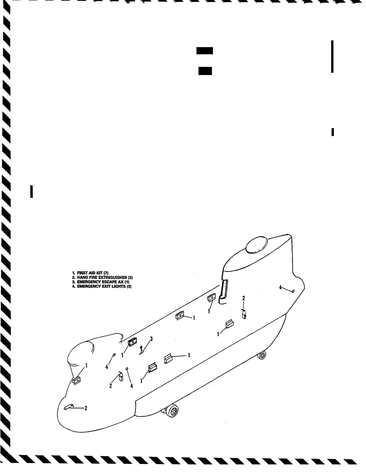
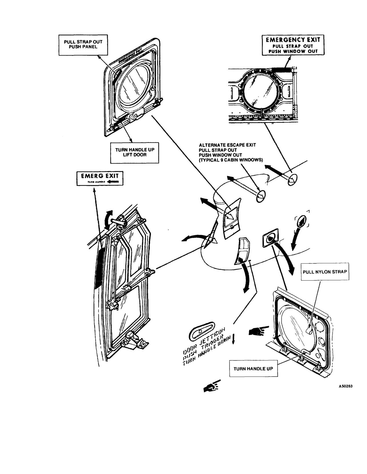
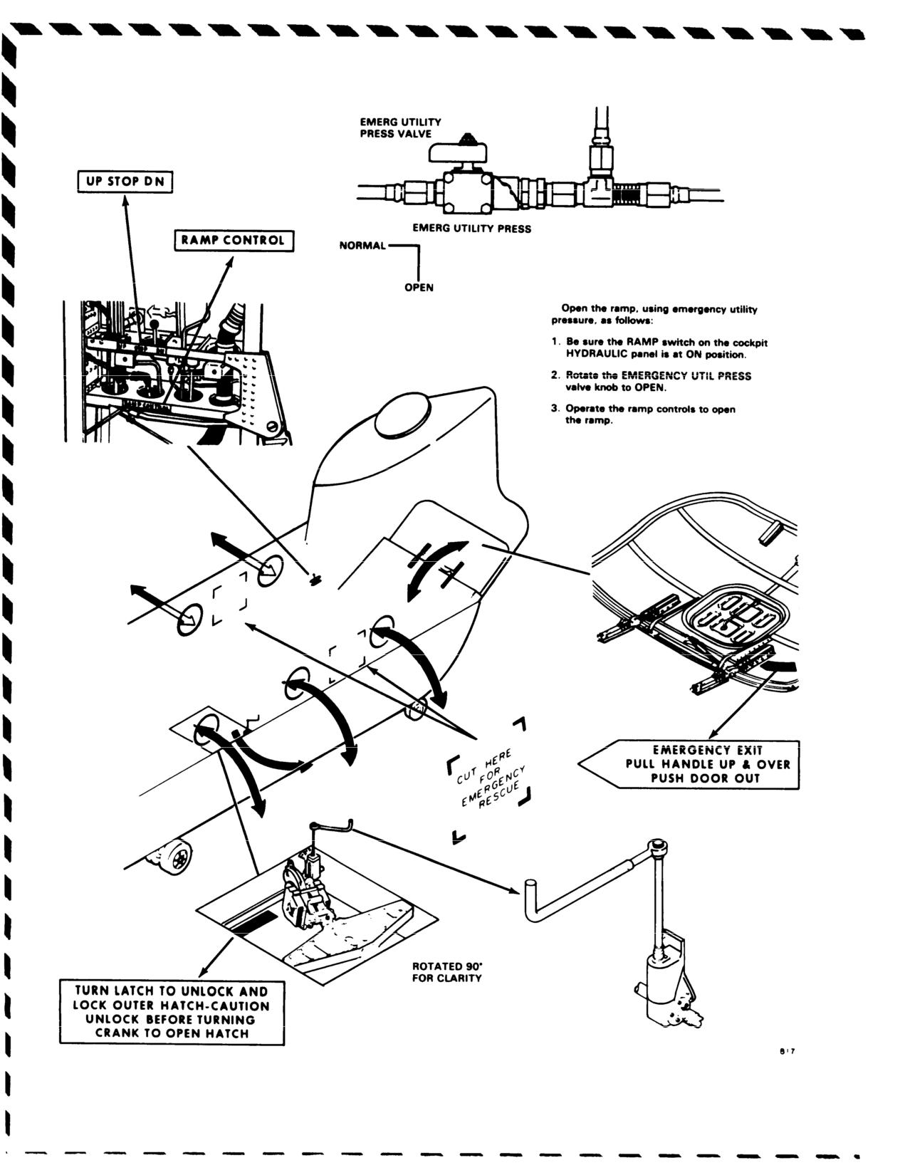
Emergency equipment, exits, and entrance routes are shown
selected NR.
in figures 9-1 and 9-2. Emergency exit door handles are
b. 712 When one engine fails, rotor speed can be
yellow and black striped. Emergency equipment consists of
expected to drop to as low as 93 percent. Safe RRPM can
seven first aid kits, three hand fire extinguishers, one
usually be regained by using engine beep trim and power
emergency escape axe, and three emergency exit lights.
available of the operating engine.
9-5. After-Emergency Action.
c. If sufficient power is not available, normal RRPM is
regained by lowering the thrust control. Procedures to be
After a malfunction of equipment has occurred, appropriate
followed after engine failure will be governed by the
emergency actions have been taken, and the helicopter is on
altitude and airspeed available for helicopter control and for
the ground, an entry must be made in the Remarks Section
maintaining sufficient RRPM for continued flight and
of DA Form 2408-13, describing the malfunction.
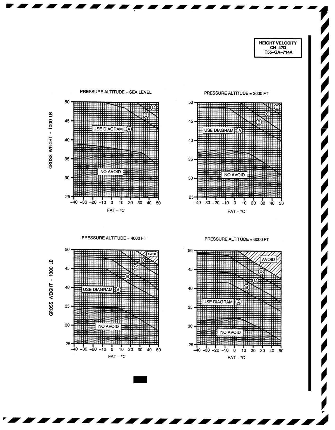
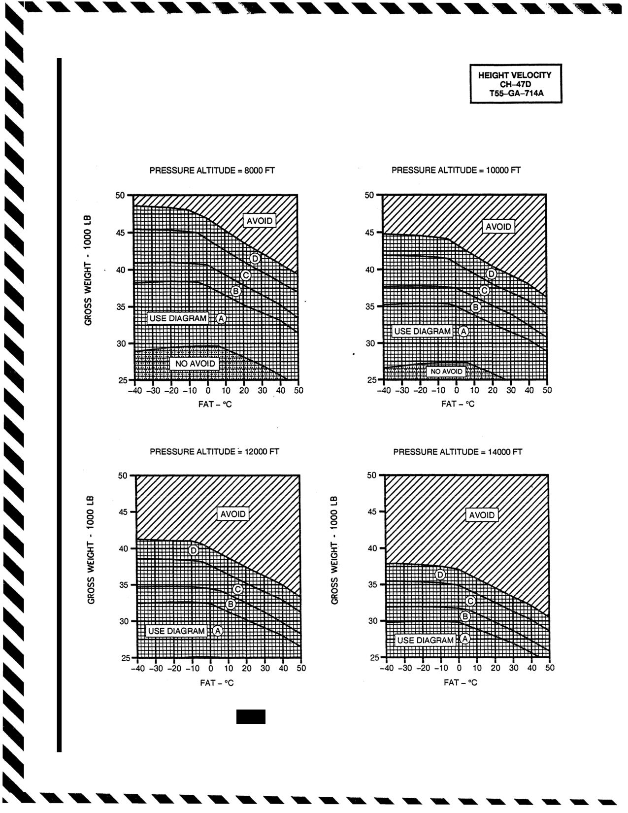
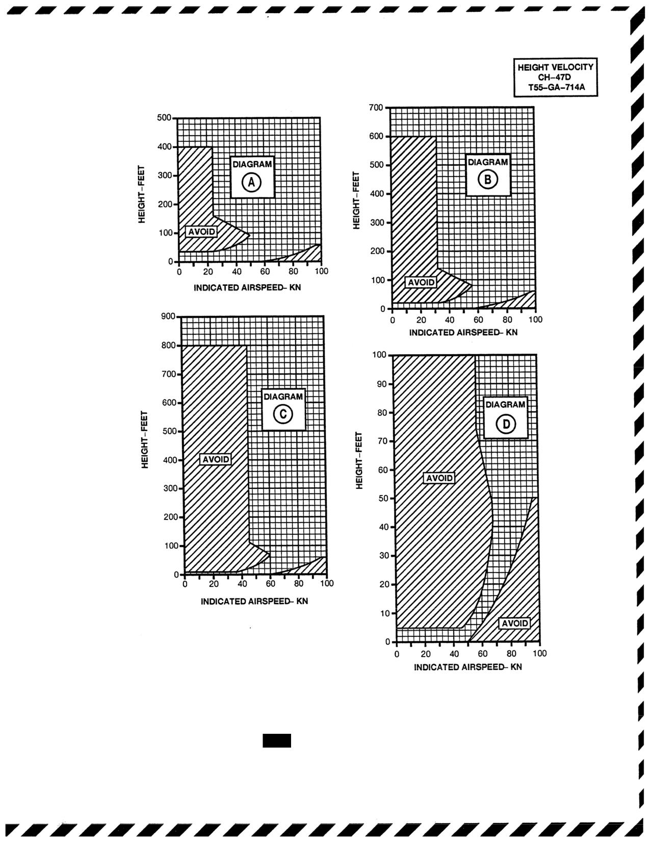
landing. The height-velocity diagram (fig. 9-4 and 9-4.2)
presents the airspeeds and wheel heights from which a safe
9-6. ENGINE.
landing can be made at various GW and temperatures
9-7. Flight Characteristics.
following a S/E failure.
a. If an engine failure occurs, no control problems exist
d. Decrease in thrust after engine failure will vary
unless power from the remaining engine is not sufficient to
with altitude and airspeed at the time of occurrence.
maintain the selected RRPM. If sufficient power is not
For example, thrust must not be decreased when an
available to maintain altitude, descend to an altitude where
engine (or engines) fail at a hover in-ground-effect
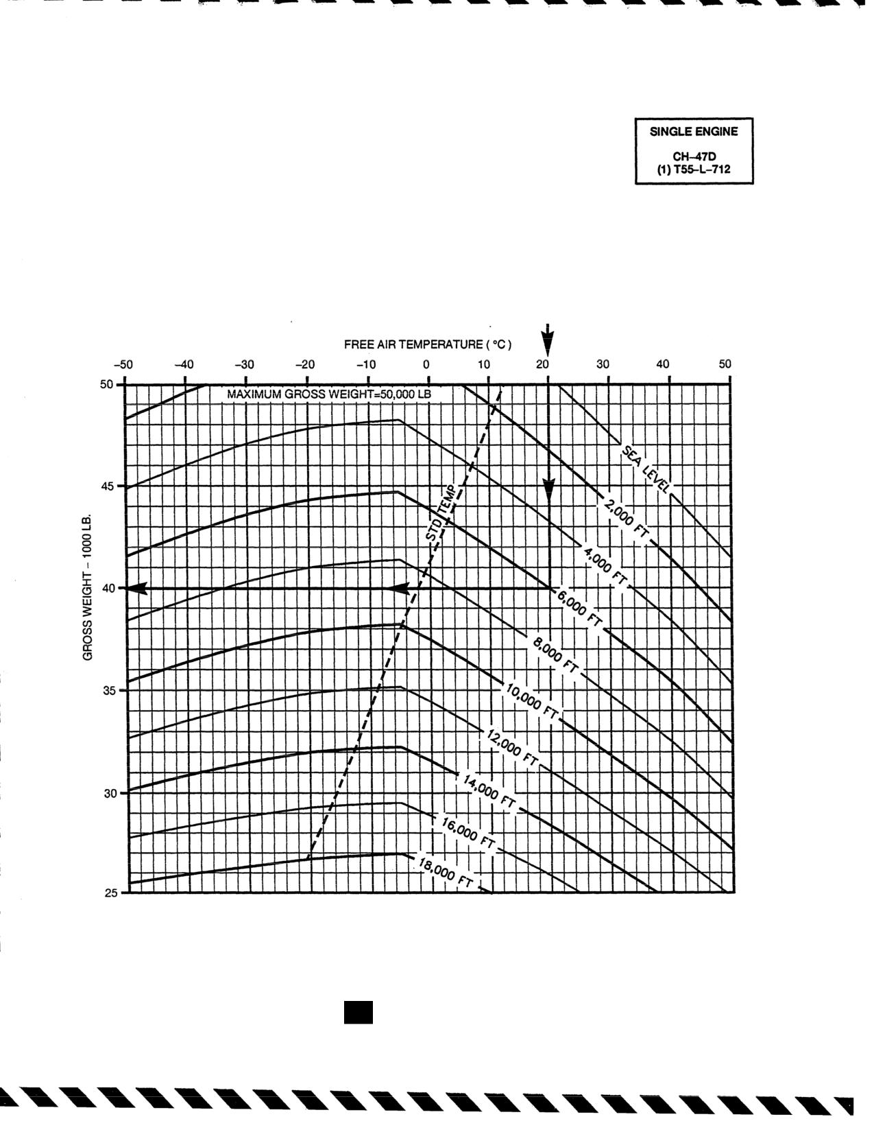
single-engine (S/E) flight can be accomplished (fig. 9-3 and
(HIGE); whereas, during cruise flight conditions, alti-
9-4.1 for S/E performance data). The best indications of
tude and airspeed are sufficient for a significant reduc-
engine failure are decreased torque on the failed engine and
tion in thrust, thereby allowing rotor speed to be
a compensating increase in torque on the remaining engine,
maintained in the safe operating range. Following an
accompanied by a droop in RRPM, and a continuing
engine failure, cyclic control is adjusted as necessary to
decrease in N1 speed below 60 percent. An engine failure
A66961
Change 13
Figure
9-1. Emergency Equipment
TM 55-1520-240-10
Figure 9-2.
Emergency Entrance and Escape Routes (Sheet 1 of
2)
Change
11
9-3
TM 55-1520-240-10
Figure 9-2. Emergency Entrance and Escape Routes (Sheet 2 of 2)
9-4
TM 55-1520-240-10
remain in hover over the desired point or to control airspeed
required airspeed. The Autorotation Approach Corridor,
and flight path in forward flight. Pedal pressure is applied as
figure 9-6 and figure 9-4.1, presents those combinations of
necessary to control aircraft heading.
airspeeds and wheel heights from which a safe autorotative
landing may be made following a second engine failure.
e. Airspeed should be maintained at the optimum for
Autorotative approaches are recommended in the caution
existing conditions for continued flight (S/E failure) or for
area. At high gross weights, the rotor may tend to overspeed
autorotational descent (dual-engine failure). As airspeed
increases above 70 KIAS in autorotation, there is a corre-
and may require thrust application to maintain RPM below
sponding increase in rate of descent (R/D). Airspeed up to
the upper limit. Thrust should never be applied to reduce
100 KIAS or Vne, whichever is slower, will increase glide
RPM for extending glide distance because this reduces
distance but should be avoided at low altitude because the
RPM available for use during touchdown. When both
time available to decelerate is critical. At airspeeds below
70
engines fail at cruise, proceed as follows:
KIAS, R/D in autorotation increases and glide distance
1. AUTOROTATE.
decreases. Gliding the helicopter in autorotation out-of-trim
will also increase R/D and decrease glide distance
2. External cargo - Jettison.
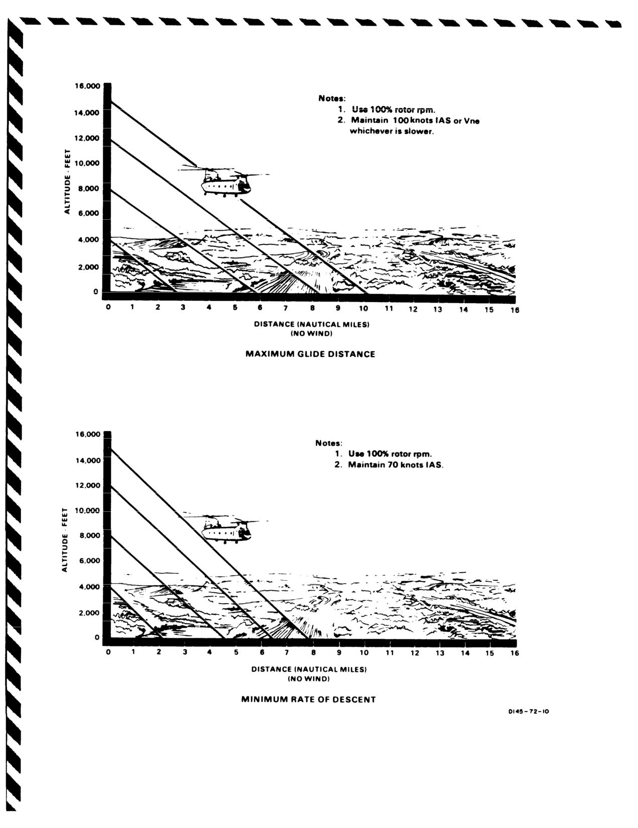
9-8. Minimum Rate of Descent - Power Off.
3. ALT
switch -
Disengage.
The power off minimum R/D is attained at an indicated
9-11. Single Engine Failure.
airspeed of approximately 70 knots and 100% RRPM (fig.
9-5).
The action taken after one engine fails will depend on
altitude, airspeed, phase of flight, areas available for land-
9-9. Maximum Glide Distance - Power Off.
ing, and S/E capability of the helicopter. Immediately after
The maximum glide distance is attained at an indicated
any engine malfunction, the flight engineer should check
airspeed of
100 knots or Vne, whichever is slower, and
the engine for the possibility of fire. If required, external
100%
RRPM (fig. 9-5).
cargo should be jettisoned as soon as possibile after engine
failure. This will help to prevent damage to the helicopter
9-10. Dual Engine Failur..
during touchdown and will reduce weight and drag, thereby
improving S/E performance.
CAUTION
Thrust control adjustments will depend on altitude at the
Jettison external cargo as soon as possible
time of the engine failure. For example, at (HIGE) below 20
after engine failure. This will help to prevent
feet, maintain thrust control position as the operative engine
damage to the helicopter during touchdown
beep trim is increased. At a hover above 20 feet, thrust
and will reduce weight and drag, thereby
should be lowered slightly to maintain at least 96 percent
improving autorotational performance.
RRPM. If altitude permits, thrust may be lowered suffi-
ciently to maintain normal RRPM.
a. Low Altitude/ Low Airspeed.
When both engines fail
at low altitude and low airspeed, sufficient altitude is not
Cyclic inputs will depend on altitude and airspeed. At a
available to increase RRPM. Establish the best autorota-
(HIGE), the helicopter should be maintained in a hovering
tional airspeed, jettison external cargo (if applicable), and
attitude. In forward flight, at low altitude (below 50 feet),
decelerate effectively prior to touchdown. Initial thrust
when S/E flight is not possible a decelerating attitude should
reduction will vary from no reduction at zero airspeed
be assumed to dissipate airspeed and aid in cushioning the
below 20 feet to full reduction at higher airspeeds and
helicopter. If airspeed is slow and altitude permits, the
altitudes. Attempt to maintain at least 96 percent.
helicopter should be placed in an accelerating attitude of up
to 30° nose-low to gain airspeed as the operative engine
CAUTION
beep trim is increased. This nose-low attitude should not be
used at an extremely low altitude because of reduced
The helicopter must be maneuvered into the
reaction time, R/D, and the response of the helicopter. Any
autorotation approach corridor prior to land-
time the helicopter assumes a decelerating attitude in close
ing to assure a safe outcome of the maneuver.
proximity to the ground, avoid rotating the aft gear into the
b. Cruise. In cruise flights up to Vne, reduce thrust
ground at touchdown.
immediately to full down position to regain RRPM. Adjust
cyclic pressure as necessary to attain and maintain the
Change 13
9-5
TM 55-1520-240-10
SINGLE ENGINE SERVICE CEILING
EMERGENCY TORQUE AVAILABLE
SERVICE CEILING
CLEAN CONFIGURATION
100% ROTOR RPM
JP-4 FUEL
EXAMPLE
METHOD
WANTED
ENTER FAT HERE
MAXIMUM SINGLE ENGINE WEIGHT
MOVE DOWN TO PRESSURE ALTITUDE
AT DESIRED SERVICE CEILING
MOVE LEFT AND READ MAXIMUM
SINGLE ENGINE GROSS WEIGHT
KNOWN
=39,990 LB
PRESSURE ALTITUDE = 6,000 FT/FAT = 20°C
DATA BASIS:
FLIGHT TEST
A9732
Figure 9-3.
712
Single-Engine Service Ceiling
9-6
Change 13
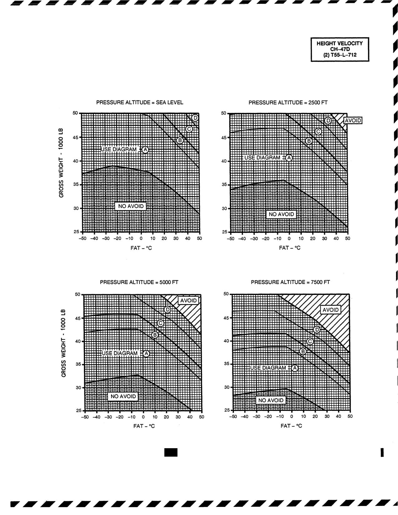
TM
55-1520-240-10
HEIGHT VELOCITY DIAGRAM FOR SAFE
LANDING AFTER SINGLE-ENGINE FAILURE
NOTE:
USE THE FOLLOWING DIAGRAMS
WITH THOSE
SHOWN ON SHEET 3
A23134
Figure 9-4.
712 Height Velocity Diagram for Safe Landing
After Single-Engine Failure (Sheet I of 3)
Change 13
9-7
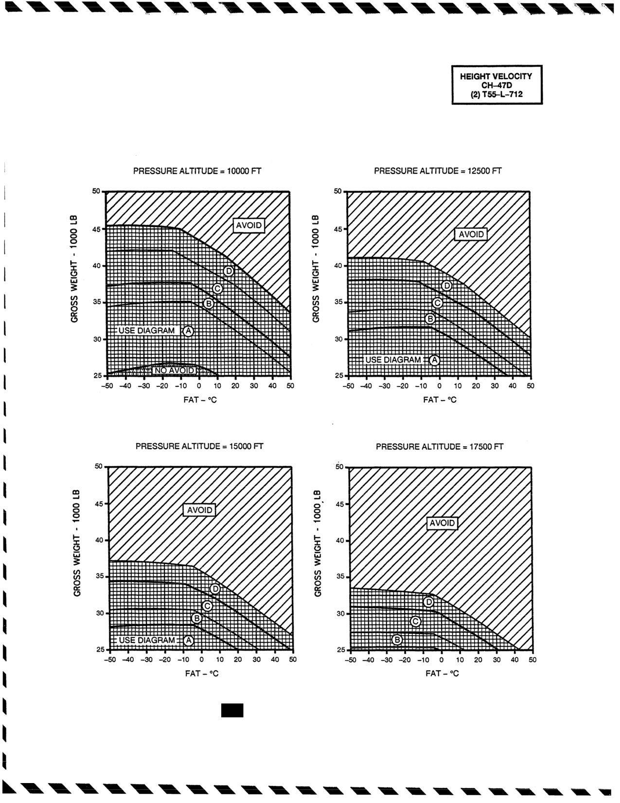
TM 55-1520-240-10
HEIGHT VELOCITY DIAGRAM FOR SAFE
LANDING AFTER SINGLE-ENGINE FAILURE
NOTE:
USE THE
FOLLOWING DIAGRAMS
WITH THOSE
SHOWN ON SHEET 3
A23155
Figure
9-4.
712 Height Velocity Diagram for Safe Landing
After Single-Engine Failure (Sheet 2 of 3)
9-8
Change 13
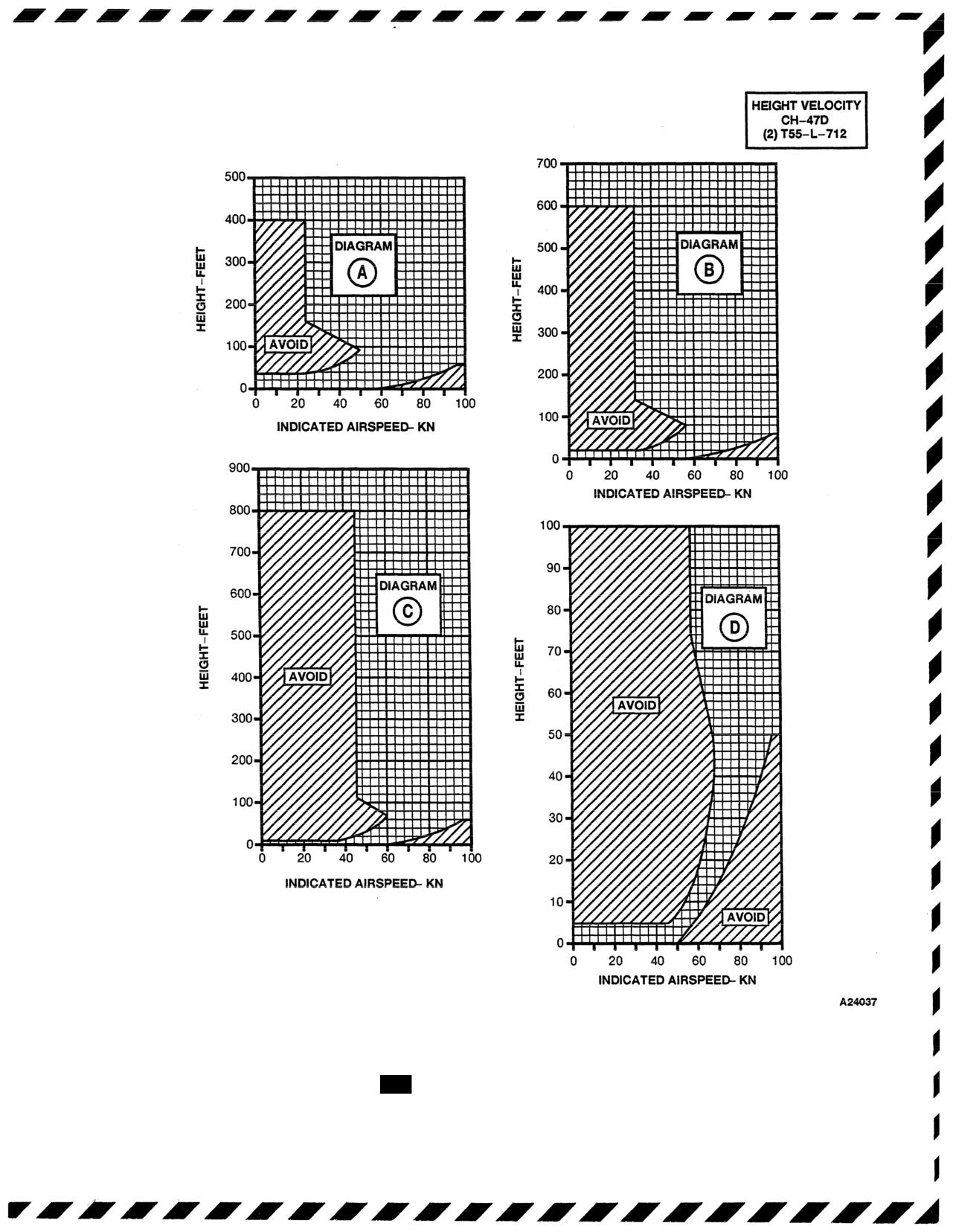
TM 55-1520-240-10
HEIGHT VELOCITY DIAGRAM FOR SAFE
LANDING AFTER SINGLE ENGINE FAILURE
Figure 9-4.
712 Height Velocity Diagram for Safe Landing
After Single-Engine Failure (Sheet 3 of 3)
Change 13
9-8.1
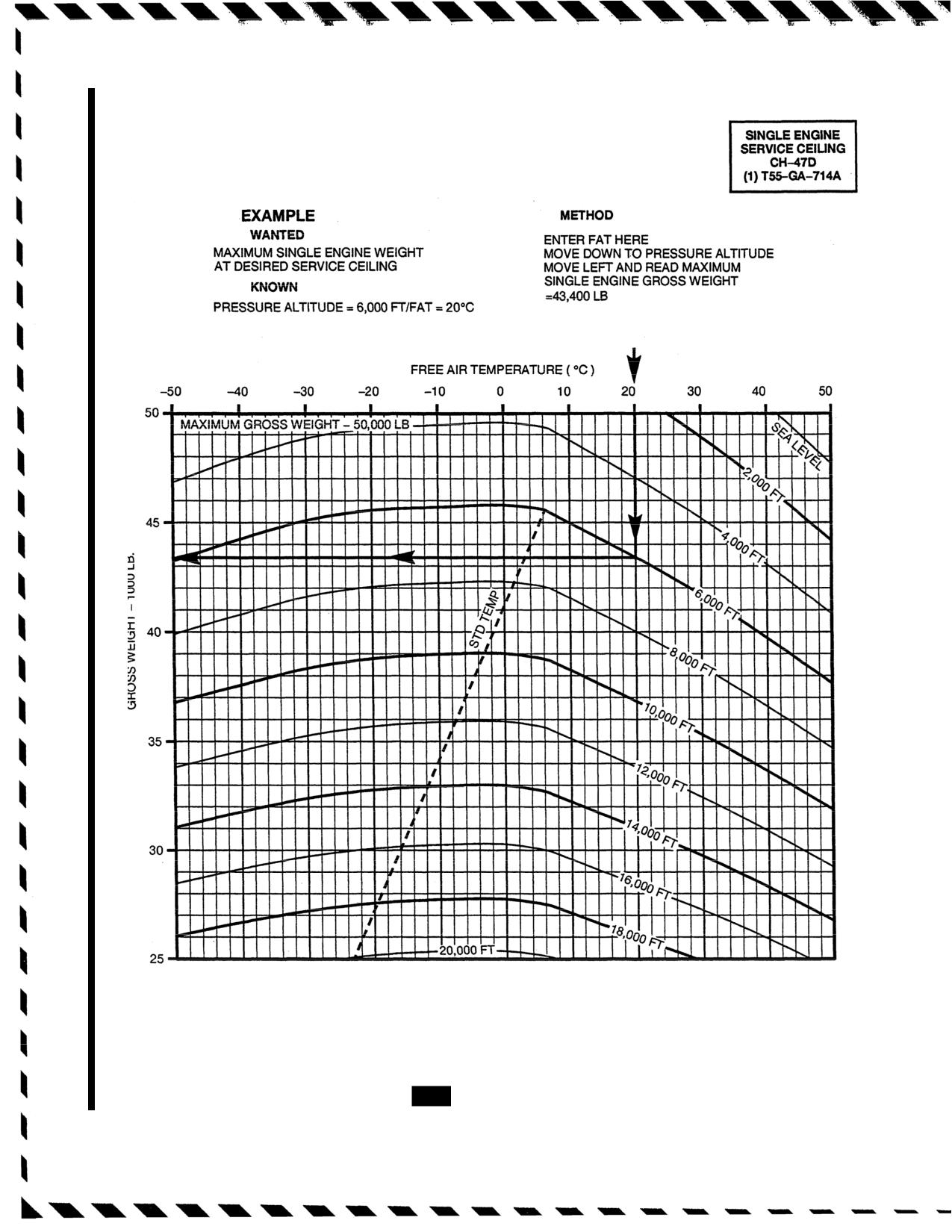
TM 55-1520-240-10
SINGLE ENGINE SERVICE CEILING
EMERGENCY TORQUE AVAILABLE
CLEAN CONFIGURATION
100% ROTOR RPM
DATA BASIS:
FLIGHT TEST
A60119
Figure 9-4.1.
714A
Single-Engine Service Ceiling
9-8.2
Change 13
TM 55-1520-240-10
HEIGHT VELOCITY DIAGRAM FOR SAFE
LANDING AFTER SINGLE-ENGINE FAILURE
NOTE:
USE THE FOLLOWING DIAGRAMS WITH THOSE SHOWN ON SHEET 3
A60125
Figure 9-4.2.
714A Height Velocity Diagram for Safe Landing
After Single-Engine Failure (Sheet 1 of 3)
Change
13
9-8.3
TM 55-1520-240-10
HEIGHT VELOCITY DIAGRAM FOR SAFE
LANDING AFTER SINGLE-ENGINE FAILURE
NOTE:
USE THE FOLLOWING DIAGRAMS WITH THOSE SHOWN ON SHEET 3
A60126
Figure 9-4.2.
714A Height Velocity Diagram for Safe Landing
After Single-Engine Failure (Sheet 2 of 3)
9-8.4
Change
13
TM 55-1520-240-10
HEIGHT VELOCITY DIAGRAM FOR SAFE
LANDING AFTER SINGLE ENGINE FAILURE
A60127
Figure 9-4.2.
714A Height Velocity Diagram for Safe Landing
After Single-Engine Failure (Sheet 3 of 3)
Change 13
9-9
TM 55-1520-240-10
Figure 9-5. Maximum Glide Distance/Minimum Rate of Descent in Autorotation
9-10
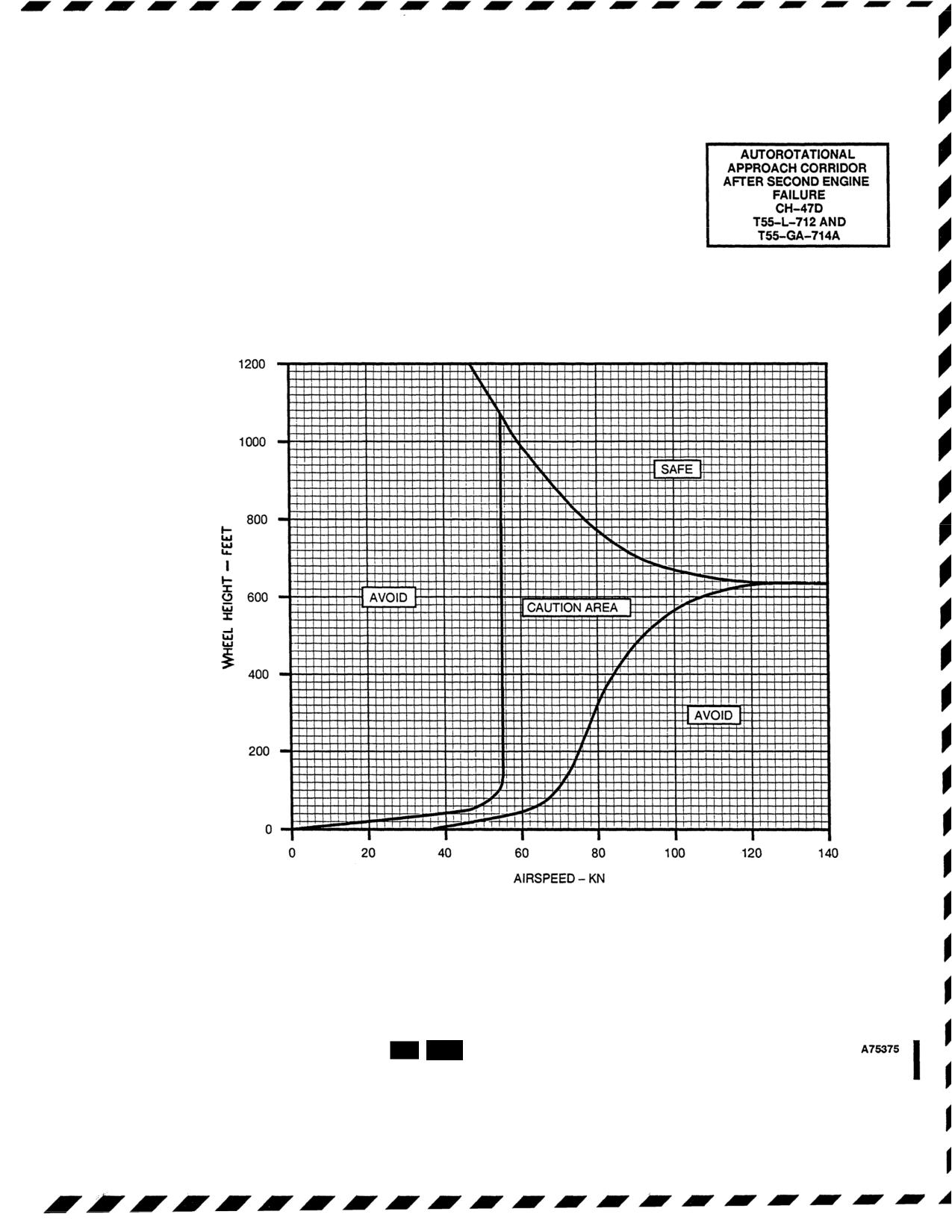
TM 55-1520-240-10
AUTOROTATIONAL APPROACH CORRIDOR
FOR SECOND ENGINE FAILURE FROM
SINGLE ENGINE LEVEL FLIGHT
Figure 9-6.
712
714A
Autorotationa/ Approach Corridor for
Second Engine Failure
Change
13
9-11

TM 55-1520-240-10
Continued flight is not possible:
9-11.1. 714A ENG 1 FAIL or ENG 2 FAIL.
Land as soon as possible.
The ENG 1 FAIL or ENG 2 FAIL caution is illuminated
whenever the engine failure logic within the DECU recog-
9-13. Engine Restart During Flight.
nizes any one of the following:
1. Power turbine shaft failure. N2 is greater than
WARNING
RRPM by more than 3%.
2.
N1 underspeed. N1 speed is below 48%.
Fire detector and extinguishing systems are
not provided for the APU. Crewman must
3.
Engine flameout.
monitor APU area for fire.
4.
Over temperature start abort (Primary mode only).
CAUTION
5. Primary system fail freeze (Primary and Rever-
sionary mode hard faults, FADEC caution is
If abnormal indications are present during
illuminated).
the restart, shut down the engine immedi-
ately.
6 . During normal shutdown as the N1 rpm goes
below 48% the ENG 1 FAIL or ENG 2 FAIL
1. APU - Start.
caution is illuminated and then is turned off 12
2. 712 ENG COND lever (inoperative engine) -
seconds after the N1 rpm drops below 40%.
STOP
2.1
714A ENG COND lever (inoperative engine)
- STOP, then GND.
9-12. Single Engine Failure - Low
3.
FIRE PULL handle - In.
Altitude/Low Airspeed and Cruise.
4.
All FUEL PUMP switches - ON.
If an engine fails under conditions that will permit S/E
flight, thrust 712 engine beep trim must be adjusted as
5.
XFEED switch - As required.
required to maintain safe RRPM. Initial thrust reduction
6.
Starting engine - Perform.
will vary from no reduction at zero airspeed below 20 feet
to a significant reduction at higher altitudes and airspeeds.
7. APU - OFF.
Attempt to maintain at least
96 percent RRPM. If the
helicopter is below the best S/E climb airspeed, forward
9-14. 712 Normal Engine Beep Trim System Fail-
cyclic must be applied to attain that speed. When (HOGE),
ure (High Side) or N2 Governor Failure.
forward cyclic pressure must be applied to attain a nose-low
Fail&e of the normal engine beep trim system to the high
attitude of up to 30° in order to gain airspeed. As airspeed
side may be recognized by increasing torque on the affected
increases to 30 knots, adjust the pitch attitude of the aircraft
engine, decreasing torque on the unaffected engine, an
to accelerate to the best S/E climb speed.
increase in RRPM, and a lack of response of normal engine
beep trim. These indications should be confirmed by ob-
If an engine fails under conditions that
will not permit S/E
serving all the engine instruments.
flight, the procedures will be essentially the same as for
continued flight, except that cyclic pressures are applied to
Controlling RRPM with the ECL must be done smoothly
decelerate the helicopter for touchdown, rather than contin-
and with care. Engine response is much faster and it is
ued acceleration. During deceleration, just prior to touch-
possible to cause the RRPM to exceed limitations or
down, avoid rotating the aft landing gear into the ground.
decrease to the point that the generators will be discon-
nected from the buses. If the thrust control is moved, it is
Continued flight is possible:
necessary to control RRPM with the engine condition lever
1..
Thrust control - Adjust as necessary to main-
and the No.1 & 2 ENGINE BEEP TRIM switch. If a
tain RRPM.
malfunction to the high side occurs, perform the following:
2.
ENGINE BEEP TRIM
switch -
RPM
1.
Thrust control - Adjust as required to maintain
INCREASE as required.
RRPM within limits.
3.
External cargo - Jettison (if required).
2.
ENG COND
lever (affected engine) -
Adjust to
4.
ALT switch -
Disengage.
a position between FLT and GND that will control
RRPM.
5.
Land as soon as practicable.
3.
ENGINE BEEP TRIM
switch NO. 1 & 2 -
6. EMER ENG SHUTDOWN (when conditions
Adjust as required.
permit).
4. Land as soon as practicable
NOTE
9-15. 712 Normal Engine Beep Trim System Fail-
If S/E flight can be maintained, an attempt to
ure (Low Side or Static).
restart the inoperative engine may be made if
there is no evidence of fire or obvious mechani-
Failure of the normal engine beep trim system to the low
cal damage.
side can be recognized by decreasing torque on the affected
9-12
Change 13
TM 55-1520-240-10
engine, increasing torque on the unaffected engine, a loss of
Two different reactions can occur depending if the engine
RRPM, a lack of response to ENGINE BEEP TRIM and N1
with the failed FADEC went into fixed fuel flow at a high
stabilized at or above ground idle (60 to 63% N1). These
fuel flow or a low fuel flow.
indications also accompany an engine failure; therefore,
In a high fuel flow situation, the FADEC on the non
engine instruments must be monitored to determine which
malfunctioning engine may cause the non malfunctioning
event has occurred. A static failure may be recognized by
engine to drop off line in an effort to maintain 100 percent
failure of one or both engines to respond to beep commands
NR (since the failed engine has a high fixed fuel flow).
or may resemble a high or low side failure when the thrust
Conversely, if the failure occurred at a low power setting,
control is lowered or raised
the malfunctioning engine will provide little or no power
If the thrust control is moved with either EMERG ENG
upon demand. These indications must be confirmed by
TRIM AUTO/MANUAL switch in MANUAL, it is neces-
observing the engine instruments display since the non-
sary to control RRPM and torque by use of the appropriate
malfunction engine could have low or high torque in
EMERG ENG TRIM INC or DECR switch. Perform the
comparison to the fixed fuel flow engine.
following:
This fixed fuel flow condition may cause an increase in NR
1. EMERG ENG TRIM
switch (affected engine)
when THRUST CONT lever is reduced. Another indication
- Adjust as required.
would be a split in TQ with upward or downward THRUST
CONT applications.
2. EMERG ENG TRIM AUTO/MANUAL
switch
(affected engine)
- MANUAL.
This fixed fuel flow condition may be capable of providing
3. EMERG ENG TRIM
switch (affected engine)
partial power at THRUST CONT application depending on
- Adjust in coordination with the ENGINE
the power that was required when the system sustained the
BEEP TRIM NO. 1 & 2 switch to normal operat-
hard failure.
ing RRPM and match torque.
Failure of the REV engine control system to a fixed fuel
flow may require the engine to be shutdown at some point
9-15.1. 714A FADEC FAILURES.
before landing to prevent NR overspeed. The ENG COND
lever will be inoperative, therefore unable to modulate
9-15.2. 714A FADEC 1 or FADEC 2 Caution.
engine N1. The FIRE PULL handle or the manual FUEL
VALVE must be used to secure the engine (if desired).
1. FADEC INC-DEC beep switch (affected engine)
- Match TQs.
9-15.5. 714A REV 1 and/or REV 2 (WITH) FADEC
LIGHT ON.
If a malfunction to the high side
2. Reduce rate of THRUST CONT lever change.
occurs, perform the following:
3. Land as soon as practicable.
1. THRUST CONT lever - Adjust.
9-15.3.
714A FADEC 1 and FADEC 2 Cautions.
2. FIRE PULL handle (affected engine) - Pull as
required.
1. FADEC ENG 1 and ENG 2 INC-DEC beep
switches
- Beep to 100 percent, match TQs.
3. NR
- Check 100 percent.
2. Reduce rate of THRUST CONT lever changes.
4. Land as soon as practicable.
3. Land as soon as practicable.
9-15.6.
714A
REV 1 and/or REV 2 (WITHOUT)
FADEC LIGHT ON
9-15.4.
714A
Reversionary System Failures.
1. Land as soon as practical.
NOTE
CAUTION
The aircrew should be alert to the possibility of
abrupt NR changes when operating the FADEC
Do not manually select Reversionary mode
in single or dual engine REV mode (s).
on affected engine as uncommanded power
changes may occur.
NOTE
9-15.7.
714A Torque Measuring System Malfunc-
The following procedure assumes the primary
tions.
and reversionary FADEC modes have failed.
Malfunctions in the torque measuring system can appear as
a frozen indication, a zero torque indication or no indica-
When operating in the reversionary mode and the reversion-
tion. If a torque measuring system malfunction occurs
ary mode sustains a hard fault, REV lor REV 2 caution is
proceed as follows:
active, a failed fixed fuel flow condition may exist. The
ENG COND lever will be inoperative, therefore unable to
1. DC Torque circuit breakers - In.
modulate engine N1. The indications may be a change in
sound, vibration absorbers may detune causing vibration,
2. LOAD SHARE switch - Check. If the switch
and a possible increase in NR when the THRUST CONT
is set to TRQ, proceed to
step 3. If the switch is
lever is reduced.
set to PTIT, proceed to
step 4.
Change 13
9-12.1
TM 55-1520-240-10
NOTE
of an engine to accelerate past 70 percent N1 when ad-
vancing the ENG COND lever to FLT. A sudden high
If the DECU fault code is 88, the DECU has not
torque clutch-engagement may cause severe engine and/
detected a fault in the torque measuring sys-
or drive train damage. A sudden engagement is indicated
tem and will continue to try to match the NO.
by a loud noise and/or a sudden large increase in engine
1 and NO. 2 engine torque. The DECU torque
torque. Should the engine transmission fail to engage,
matching logic will try to increase the low en-
perform the following:
gine’s torque. This will cause a transient rotor
speed excursion possibly up to 103% from an
initial 100% selected condition. The power tur-
WARNING
bine governor will automatically bring the rotor
speed back to 100%. However, a split in actual
Do not shut down both engines simulta-
engine torque will occur as evidenced by PTIT
neously. Maintain RRPM with the engaged
and N1 indicators. If the DECU fault code is A1,
engine until affected engine N1 reaches
the DECU has detected a failure of the torque
zero (0).
measuring system and has automatically
switched to N1 load share.
1. ENG COND lever (affected engine only -
3. Load Share switch - Select PTIT.
STOP.
4. Fuel flow - Monitor. 1896 PPH is equal to
When N1 reaches zero (0):
approximately 100% torque at 100% rotor
2. ENG COND lever (engaged engine) - STOP.
speed.
5. Verify that PTITs are matched.
9-17. Engine Shutdown - Complete Electrical
Failure.
6. Minimize power as practical.
F
1. FUEL VALVE #1 and #2 ENGINE - CLOSE.
7. Land as soon as practicable.
2. Normal shutdown - Perform.
9-16. Engine Transmission Clutch Failure to En-
gage.
9-18. Engine Shutdown - Condition Lever Failure.
An engine transmission clutch failing to engage is most
Should the engine condition lever fail to shut down or
likely to occur when the engine condition lever is ad-
control an engine, use the following procedure for engine
vanced from GND to FLT or during engine start. The
shutdown.
indications of an engine transmission clutch failing to en-
1. FIRE PULL handle (affected engine) - Pull.
gage are: a loss of torque indication for an engine or
erratic torque indications for an engine or failure of the N1
2. Normal shutdown - Perform.
Change 17
9-12.2
TM 55-1520-240-10
9-19. Engine Shutdown with APU or APU Generator
9-21. ROTOR, TRANSMISSION, AND DRIVE SYS-
Inoperative.
TEMS.
WARNING
CAUTION
When the rotors stop turning, no hydraulic
If an interposer block or rotor blade droop
stop is not in place, the flight engineer will
pressure is available to motor the engines.
notify the pilot in command. All
In the event of internal engine fire when
non-crewmembers will evacuate the
engine motoring cannot be accomplished,
aircraft to a safe position. If possible, crew
use fire extinguishing equipment as nec-
will contact maintenance and attempt to
essary to extinguish the fire.
engage interposer block with a high
Apply external electrical and hydraulic power (if avail-
pressure water stream or prepare aircraft
for shutdown in such a way as to minimize
able) and continue with a normal shutdown. If external
damage to aircraft and components and
electrical and hydraulic power is not available, proceed
prevent injury to personnel. If interposer
as follows:
blocks appear to be in place, the flight
1. No. 2 Engine - Perform a normal shutdown.
engineer will clear the pilot to shut down
the first engine. After the first engine is
2. All unnecessary electrical switches (except
shut down, the flight engineer will observe
BATT switch) - OFF.
the rotor blade tip path of the forward and
3. GEN 1 and 2 switches - OFF.
aft rotor heads. A rotor blade drooping
significantly lower than the other blades
4. ENG COND 1 lever - GND. Wait until PTIT
indicates a missing droop stop. In this
decreases and then begins to increase; then,
case the remaining running engine
move the ENG COND 1 lever to STOP.
condition lever (ECL) should be advanced
5. ENG 1 START switch - MTR until rotors stop
until sufficient rotor RPM is achieved to lift
or PTIT is below 260°C.
rotor blades off droop stops to insure no
blade contact with airframe and
6. Normal shutdown - Perform.
maintenance contacted to prepare aircraft
for an emergency shutdown that will
9-20. Engine Oil - Low Quantity/High Temperature/
minimize damage to aircraft and injury to
High or Low Pressure.
personnel.
A low engine oil quantity condition will be indicated by the
9-22. NO. 1 or NO. 2 ENG XMSN HOT Caution.
lighting of the NO. 1 ENG OIL LOW or NO. 2 ENG OIL
1. EMER ENG SHUTDOWN.
LOW caution light. When either one or both of these
F
2. Affected engine transmission - Check.
caution lights come on, about 2 quarts of usable oil re-
main in the respective engine oil tank. If one or both of the
3. Land as soon as possible.
caution lights come on, check oil temperature and oil
9-23. Transmission Debris Screen Latches.
pressure indicators (affected engine) for abnormal indi-
Trouble developing in any of the five transmissions may
cations. If the indication on the oil temperature indicator
be indicated by a tripped latch indicator. This information
is high or the indication on the oil pressure indicator ex-
will be presented on the flight engineer’s MAINTE-
ceeds limits, high or low, perform the following:
NANCE PANEL but will not be shown in the cockpit. If an
indicator trips:
1. If engine power is required for flight:
FWD, COMB, or AFT DEBRIS SCREEN indicator:
Land as soon as possible.
F RESET/GND/TEST switch - RESET.
2. If engine power is NOT required for flight:
If indicator does not reset:
a. ENGINE CONDITION lever (affected en-
Land as soon as possible.
gine) - STOP.
LEFT or RIGHT DEBRIS SCREEN indicator:
b. Land as soon as practicable.
F RESET/GND/TEST switch - RESET.
9-20.1
Engine Chip Detector Caution Light ON.
If indicator does not reset and engine power is not re-
quired then:
If either NO. 1 or NO. 2 ENG CHIP DET caution light
comes on, perform the following:
1. EMER ENG SHUTDOWN.
2. Land as soon as practicable.
1. If engine power is required for flight:
If engine power is required:
Land as soon as possible.
Land as soon as possible.
2. If engine power is NOT required for flight:
9-24. Transmission Low Oil Pressure or High Tem-
a. ENGINE CONDITION lever (affected en-
perature Indications.
gine) - STOP.
Developing trouble in the transmissions can be identi-
b. Land as soon as practicable.
fied by high oil temperature or low oil pressure, as
Change 17
9-13
TM
55-1520-240-10
indicated by transmission temperatLEFT o
RIGHT
tors and cautions. If an abnormal temperature or pressure
Engine power is not required:
indication develops, closely monitor the caution capsules.
1.MER ENG SHUTDOWN.
The XMSN OIL PRESS (main or aux) and XMSN OIL HOT
2. Land as soon as practicable.
caution capsules operate independently of the pressure and
temperature indicating system and Engineepowernisrequired:a low pres-
sure or high temperature conditionLand as soon as possible.
information may be obtained by the flight engineer checking
Malfunctions.
the MAINTENANCE PANEL. The transmi9-28.1.nTorqueMeasuringtSystem
and pressure selector switches shaMalfunctions in the torque measuring sy
mining the defective transmission.the torquemeter as fluctuations, zero t
gish movement, indications that are out
9-25.
XMSN OIL PRESS Caution.
If the XMSN OIL
tionary indication. Fluctuations in tor
PRESS caution capsule comes on. the following actions
indicative of
an electrical malfunction
should be taken:
this occurs. proceed as follows:
FWD
orOMB (MIX):
1. AC and DC TORQUE circuit breakers
1. Al
- Descend to minimum safe a2.N1sde.Monitor when power changes a
2. Airspeed - 100 KIAS or Vne whichinsuring power
outputs are matched.
3.Fuel flow indicator - Monitor for
3. Land as soon as practicable.
flows.
AFT or AFT SHAFT (confirm AFT SHAFT with flight
4.Land as soon as practicable.
engineer):
9-29. FIRE.
Land as soon as possible.
The safety of helicopter occupants is
LEFT
o
RIGHT
ation when fire occurs; therefore, it i
Engine power is not required.
effort be made by the flight crew to pu
1. EMER ENG SHUTDOWN.
ground, it is essential that engines b
passengers be evacuated, and fire figh
2. Land as soon as practicable.
ately. If the
rborne when fire occurs. the
Engine power
is required:
important single action that
and
Land as soon as possible.
as soon as possible. Whether on the ground or inf
mandatory cockit windows, air control
9-26.
XMSN OIL PRESS and XMSN AUX OIL
cockpit air kno
to prevent smoke enteri
PRESS or XMSN CHIP DET Caution.
cockpit, unless the smoke and fume eli
Land as soon as possible.
has been eIncflight the pilot should
smoke and fume elimination
to pre-
9-27.
XMSN AUX OIL PRESS Caution.
If the
vent smoke and fumes from entering the
XMSN AUX OIL PRESS caution capsule comes on, the fol-
guishers should be used to control or e
lowing actions should be taken:
MAIN XMSN (FWD, COMB (MM), or AFT)
Main transmission oil pressure and temperature are
Use fire extinguisher only in well-ventilated
abnormal:
areas because the toxic fumes of the extin-
Land as soon as possible.
guisher agent can cause injury.
Main transmission oil pressure and temperature are
normal:
9-30. ENGINE HOT START.
A hot start will
Land as soon as practicable.
detected by a rapid and abnormal rise
observing flames and black smoke comin
9-28.
XMSN OIL HOT Caution.
If the XMSN OIL
tail cone. Complete the following on th
HOT caution capsule comes on, the following actions should
be taken:
1. ABORT START.
FWD
orOMB (MIX):
Land as soon as possible.
9-30.1.
RESIDUAL FIRE DURING SHUTDOWN.
AFT transmission is indicated:
residual engine fire may occur during s
1
Electrical load - Reduce as much as possresidual fuel igniting in the combustio
2. Land as soon as possible.
9-14
Change
9
TM 55-1520-240-10
1
ABORT START.
NOTE
2. FIRE PULL handle (affected engine) -
Immediately motor engines alternate
Pull.
rotors are stopped. to reduce the p
engine residual fire.
9-31.
Auxiliary Power Unit (APU) Fire.
Normally
an overtemperature condition will 9-32.useEngineor Fuselage Fire - Flight.
Visible
switch to stop APU operation: howeflames, smoke coming from the engine o
in the APU, complete the following:
respective FIRE PULL handle:
1. APU switch - OFF.
1
Land as soon as possible.
F
2
Engine fire confirm.
2
ABORT START.
3
EMER ENG SHUTDOWN
(affected engine)
Change
9
9-14.1/(9-14.2 blank)
TM 55-1520-240-10
After landing:
EMER ENG SHUTDOWN.
5. RAMP EMER - As required.
9-33. Engine Compartment, Fuselage, or Electri-
cal Fire - Ground.
NOTE
1
EMER ENG SHUTDOWN.
The combination of steps 2, 3, a
2. APU switcOFF
-
(if operating).
evacuates the cockpit and forwa
3. BATT
switcO
FF.
-
smoke and fumes at airspeeds abo
Opening the cargo loading ramp e
9-34. Electrical Fire
- Flight. Before shutting off all
main cabin. With items in steps
electrical power, the pilot must consider the equipment that
opened, intensification of a smol
is essential to the current flight regime; e.g. flight instru-
occur. If the source of the fi
ments, flight control
anding as soon
determined, close the cargo load
possible cannot be made, defective circuits may be
keep the pilots windows and the
isolated by selectively turning off electrical equipment
the main cabin door open. This w
and/or pulling out circuit breakers.
pilots to see the instrument pan
references for landing
A dual engine flameout may occur if both
6. Copilot’s sliding window
- C
generator switches are turned off above 6,000
feet PA. All fuel boost pumps will be inop-
7. NVG curtain
- Open (if appli
erative.
9-36. FUEL SYSTEM.
1. Airspeed - 100 KIAS or Vne whichever is
9-37. Aux Fuel Pump Failure.
slower.
An auxiliary fuel pump failure will
NOTE
PRESS indicating light, on the FUE
LCT and DASH actuators will illuminating and/or the fuel quanti
grammed at the airspeed at whicremaining at the
same level. Should
were turned off. Normal enginefollows:disabled
when generators are turned off.
1. FUEL QUANTITY selector switc
2. GEN 1 and 2
swit
-OFF.
If one or both auxiliary fuel tanks have fuel remaining:
3
Land as soon as possible.
2. AC-DC FUEL PUMP circuit brea
After landing:
in.
4
EMER ENG SHUTDOWN.
3. FWD and AFT AUX FUEL PUMP
5. BATT
switcO
FF.
-
(affected side)
- OFF.
9-35. Smoke and Fume Elimination.
4. AUX FUEL PUMP switch - ON (e
with fuel remaining).
1. Airspeed - Above 60 KIAS.
2. Pilot’s sliding window - Open.
If AUX PRESS indicating light remains on:
3
Helicopter attitude - Yaw left, one half to one
5. AUX FUEL PUMP switch(es)
(
ball width on turn and slip indicator.pump(s)
)
- OFF. Monitor FUEL
4. Upper half of main cabin door - Open.
indicator for the affected tan
6. AUX FUEL PUMP switch(es)
- O
tive pumps or Off for inoperat
The cargo ramp can be opened or closed
9-38. Fuel Venting.
either manually by the flight engineer using
the lever on the ramp control valve or elec-
Fuel venting from either main tank
trically by the pilot using the RAMP EMER
bility of fuel cell overpressurizat
control switch on the overhead HYD panel. If
1. AUX FUEL PUMP switches (affected side) -
the flight engineer is unable to manually
OFF.
position the ramp, the pilot should attempt to
check that the ramp is clear of personnel and
2. Main tank (affected side)
-
equipment before opening or closing it. Un-
When 1,000 pounds of fuel remain:
announced opening or closing of the ramp
may lead to injury to personnel, or damage to
3. AUX FUEL PUMP switches - ON
equipment.
quantity).
Change
9
9-15
TM 55-1520-240-10
When tank quantity reaches 1,600 pounds:
If any other system caution comes on or a system is lost, a
bus tie does not exists. The primary caution segment lights
4. AUX FUEL PUMP switches - OFF.
to look for in determmmg whether or not a bus tie exists are
5. Steps 2 through 4 -
Repeat until auxiliary tanks
L and R FUEL PRESS, NO.1 and NO.2 RECT OFF, and
are empty.
NO.1 AND NO.2 AFCS OFF.
9-39. L or R FUEL PRESS Caution.
If no bus tie exists and a generator cannot be restored:
If both main tank fuel pumps fail, fuel will be drawn from
Land as soon as possible.
the main tanks as long as the helicopter is operated below
9-44. NO. 1 and NO. 2 GEN OFF Cautions.
6,000 feet pressure altitude. If the L or R FUEL PRESS
caution comes on.
Should both generators fail, both transformer-rectifiers will
1.
XFEED
switch - OPEN
(above 6000 feet PA).
also be disabled. This condition will be indicated by loss of
both AFCS (which can result in abrupt attitude changes) the
2.
FUEL PUMP(S) circuit breakers - Check in.
lighting of both AFCS OFF, GEN OFF, and RECT OFF
caution. Since there will be a loss of all primary attitude,
Pump(s) are operational -Proceed with step 3.
instrument, navigation, and stabilization systems, the pri-
Pump(s)
are not operational-Proceed with step
4.
mary concern is to restore electrical power. The only
3. XFEED switch - CLOSED.
electrical power available will be 24-volt DC from the
battery.
4. FUEL PUMP switches - OFF (inoperative
pump(s)).
CAUTION
9-40. Fuel Low Caution.
If both generators fail, the main tank boost
If a L FUEL LOW or R FUEL LOW caution comes on,
pumps will be inoperative. If flight is con-
perform the following:
ducted above 6,000 feet PA, descend below
6,000 feet PA as soon as possible to avoid a
1. Fuel quantity -
Check individual tanks.
dual engine flameout. If applicable, reduce
2. XFEED switch - As required.
airspeed to 100 KIAS or Vne, whichever is
slower.
712 Also all normal beep trim func-
3. Land as soon as practicable.
tions will be inoperative. EMERG ENG
TRIM switch for both engines should be
9-41. FUEL LOW and FUEL PRESS Cautions.
placed to manual. The control of engine RPM
If the FUEL LOW and FUEL PRESS cautions come on
will be accomplished via the EMERG ENG
perform the following:
TRIM 1 and 2 switches. LCT and DASH
actuators will remain programmed at the
airspeed at which the generators failed.
WARNING
If both generators fail, perform the following:
Failure of main tank fuel boost pumps with
the crossfeed open and a fuel low condition
1. AFCS SYSTEM SEL
switch -
OFF.
may result in a dual engine flameout. Nose
2. PDPs -
Check circuit breakers and gang bar
low attitude should be avoided.
down.
1. XFEED - CLOSED.
3. Each GEN
switch -
OFF RESET,
then ON.
2. Land as soon as Possible.
Electrical power is restored (from either generator):
9-42. ELECTRICAL SYSTEM.
1. PDP’s -
Gang Bar Up.
2. Land as soon as practicable.
9-43. NO. 1 or NO. 2 GEN OFF Caution.
Electrical power is not restored:
NOTE
1. APU - Start.
If either an AC or DC system fails with no bus
tie, the hydraulic oil cooler fans will not func-
2. APU GEN - ON.
tion.
3. Land as soon as possible.
If only the NO. 1 or NO. 2 GEN OFF caution is illuminated,
a bus exists.
NOTE
Regardless of which condition exists, (one or
1. GEN switch -
OFF RESET, then ON.
both main generators inoperative) the defective
If the caution remains on:
generator(s) must be left OFF. If the fault is
cleared and power is restored and a generator
2. GEN switch - OFF.
switch was unintentionally left ON unantici-
3. Land as soon as practicable.
pated transients in the helicopter may occur.
9-16
Change 13
TM
55-1520-240-10
9-45.
NO. 1 or NO. 2 RECT OFF Caution.
NOTE
If a DC bus-tie does not occur (No. 2 Rect Off),
power to open the cargo hooks in normal mode
is not available and the associated hydraulic
cooler fan will not function. Other cautions
will be on, such as L FUEL PRESS (if
crossfeed valves are closed).
DC bus tie has occured (only the RECT OFF caution will be
on).
1. PDPs
- Check.
2. Land as soon as practicable.
DC bus tie has not occurred.
Land as soon as possible.
Change
9
9-16.1/(9-16.2 blank)
TM 55-1520-240-10
9-46. NO. 1 and NO. 2 RECT OFF Cautions
1. PWR XFER 1 and 2 switch (affected system) -
ON.
When both transformer-rectifiers (TR) fail, all equipment
on the No. 1 and No. 2 DC buses will be disabled.
F
2.
MAINTENANCE PANEL - Monitor.
Equipment which will be lost includes all fuel boost pumps,
3. Land as soon as possible.
both AFCS, accompanied by abrupt attitude change, and
both torque indicators.
712
Normal engine beep trim is
High fluid temperature is evident:
also disabled, therefore, changes in power settings
Land as soon as possible.
should be minimized. The only source of DC power is the
battery.
9-51. NO. 1 and NO. 2 HYD FLT CONTR Caution.
CAUTION
If both hydraulic systems fail, flight controls cannot be
If both transformer rectifiers have failed, the
moved. In addition, the NO. 1 and NO. 2 AFCS-OFF
main tank boost pumps will be inoperative. If
caution will illuminate. Both AFCS systems must be
flight is conducted above 6,000 feet PA, a
turned OFF as soon as possible.
descent below 6,000 feet PA must be initiated
as soon as possible to avoid a dual engine
1. PWR XFER 1 and 2 switches - ON.
flameout. If applicable, airspeed should be
2.
Land as soon as possible.
reduced to 100 KIAS or Vne, whichever is
slower. LCT and DASH actuators will remain
9-52. UTIL HYD SYS Caution.
programed at the airspeed at which the trans-
Depending upon the nature and location of the system
former rectifiers failed.
712
All normal engine
failure, it may not be possible to operate the following
beep trim functions will be inoperative. The
items of equipment: APU, engine starters, ramp and
control of engine RPM will be accomplished
cargo door, wheel brakes, swivel locks, power steering,
via the EMERG ENG TRIM 1 and 2 switches
cargo hook, PTUs and winch. Should a failure occur in any
once the EMERG ENG TRIM guarded switch is
of these subsystems:
at MANUAL.
If both transformer rectifiers fail, perform the following:
Fluid loss is evident:
1. AFCS SYSTEMS SEL switch - OFF.
1. Isolation switch - OFF.
2. PDPs - Check circuit breakers and gang bars
2. Land as soon as possible.
down.
3. DC equipment not required - OFF or pull out
High fluid temperatures is evident:
circuit breakers.
Land as soon as possible.
4. Land as soon as possible.
9-47. BATT SYS MAL Caution.
Fluid loss is not evident:
1. BATT CHGR circuit breaker - Out, then in.
1. APU - Start.
If the BATT SYS MAL caution remains on:
2
Land as soon as practicable.
2. BATT switch - OFF.
F
3. MAINTENANCE PANEL - Monitor.
9-48. HYDRAULIC SYSTEMS.
9-53. Emergency Descent.
9-49. Hydraulic System.
CAUTION
WARNING
In executing any emergency descent, regard-
The power transfer pumps were designed for
less less of energy power available, it is
ground checkout of the flight control system
imperative that the helicopter be maneuvered
and have the capacity to pressurize the sys-
into a position from which a survivable land-
tem for gentle maneuvers only. Rapid control
ing can be accomplished. Transition from the
inputs must be avoided to preclude upper
following descent techniques into an
boost actuator stalling (binding) and/or jam
appropriate landing attitude / airpseed / R/D
button extensions. Use of the power transfer
should begin prior to descending below 600
pumps in flight is restricted to these emer-
fee AGL. The emergency descent procedures
gency conditions only.
below will result in R/D which exceed the
9-50. NO. 1 or NO. 2 HYD FLT CONTR Caution.
rates displayed on the VSI.
Fluid loss is evident:
An emergency descent is a maximum performance
Land as soon as possible.
maneuver in which damage to the helicopter or power
Fluid loss is not evident:
plants must be considered secondary to getting the
9-17
Change 16
TM
55-1520-240-10
helicopter on the ground. No one proc4. RecoveInit
iate at
600
feet AGL.
considered the best for all given situatHelicopter should be returned to win
must consider his flight profile in selecting the emer-
9-54. Autorotative Landing.
gency descent procedure he will execute. RRPM greater
than 102 percent significantly increaa. An autorotative
landing will be accom
tion and should serve as a good RRPMfailure of both
engines. Maintain speed at
maneuver. The following techniquesminimum (R/D) airspeed in autorotation w
greatest IUD from higher altitude.
Maintain RRPM
108
percent by adjusting thru
as necessary. Do not allow RRP
1
High Speed Straight Ah
his procedure
percent prior to deceleration for touchdo
produces the highest (R/D) but also produces high
airspeeds which must be dissipated priob. At approx50 toa75
elf
eet above ground level.
actual touchdown area may vary froapply aft cyclic control as nec
0°
touchdown point due to the glide annose-high attitude) to initiate a smooth
the initial deceleration to reduce Maintain alinement of the helicopter wit
by application of pedals and cyclic co
1. Thrust
- Lower. Adjust RRareao
thrust as required to prevent RRPM from
maintain appro
104
percent.
above the maximum.
2. Airs
- Adjust (appr130
to
0
c. At approximately 15 feet aft gear
KIAS)
sufficient thrust to slow the R/D, assis
3. Recove
nitiate at
600
feet AGL
and effect a smooth touchdown in ETL. The
and decele
70-80 KIAS
to enter tthrust applied and the rate at which it
autorotative corridor.
vary depending upon the wind, load, and
encing factors. Maintain the landing att
NOTE
ble, with cyclic and thrust until forw
Allowing the RRPM to increase dceased,e-
then smoothly lower thrust until
celeration will reduce the fllanding gear
touches the ground. Apply
which will occur when the decelrequired.is
initiated.
d. Whenever a touchdown into the wind u
controlled conditions cannot be made, exec
ing. It is better to perform a
Out-of-Trim DT
is procedure places thwind land
ter in a high R/D and allows simultaing, which can be
executed from sufficie
smoke and fume elimination procedurstop drift and reduce the R/D, than to c
allows good landing area predictabilinto
the wind with the great possibility o
and damage to the helicopter. Decelerate t
1.Thrust control
- Lower. Adjust RRPM to
at the same altitude as though the hel
maintain appro
104
percent.
making the entire approach into the wind.
2.
Airspeed - Adjust to maintain approximately
e. Stop all drift and perform the initia
100 KIAS.
the upwind aft landing gear. In a strong w
3.
Trim- Adjust cyclic and pedalnecessary to hold the helicopter in what i
minimum
ne ball width out of tslip by cross control.
righ (left pedal forward) equivalent to a bank
f. After touchdown, allow the helicopter
angle of appr
8 to 10
degrees rigth
e other landing gear. Perform the grou
and a zero turn rate.
same manner as a landing made into the win
4.Recover
Initiate at
600
feet AGL.
ve.
retrim the ball to centered f9-55. Landing With One Engine Inoperati
airspeed to app
70 KIAS
When committed to a S/E landing, it is
possible to terminate the approach at a ho
Low Speed Maneuvering
aneuvering the heli-
it is recommended that a running landi
copter in steep turns as described below should allow
ates on the ground
the pilot to fly the helicopter ovproach which termin
allow.
during the descent, observe his areaterrain conditions
down, and make adjustments as required.
9-56. Landing in Trees.
1.
Thrust control
- Lower. Adjust RRPM to
External cargo must be jettisoned as soon
maintain appro
102
percent.
a landing in trees is imminent, it IS impo
2.
Airspe-dAdjust airspeed
0 to
forward motion of the helicopter before
90 KIAS.
trees.
3.
Bank ang
Adjust as required. Bank angles
Power on:
of up
0 degrees will result in the desired
rates-of-descent.
1.pproach to a hover - 5 to 10 feet.
9-18
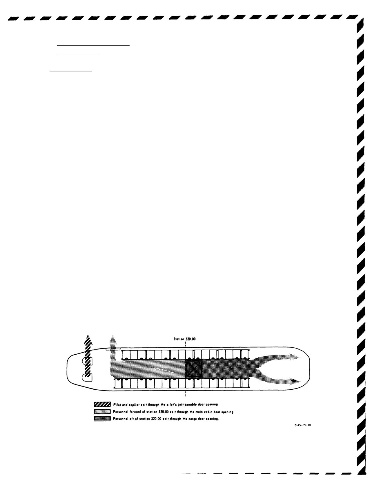
TM 55-1520-240-10
2. EMER ENG SHUTDOWN.
operating range by adjusting the thrust as necessary. At
approximately
100 feet above the water, perform a
3. AUTOROTATE.
gradual longitudinal flare. Allow the RRPM to increase
Power off
to the upper limit so that maximum benefit can be
AUTOROTATE.
gained from the inertia to cushion the touchdown.
b. At approximately
30 feet above the water, the final
9-57. Emergency Entrance.
attitude should be adjusted, not to exceed
20° nose-up.
a. Access to the cockpit is through the pilot and
An excessive nose-up attitude will reduce the clearance
copilot jettisonable doors. (Figure 9-2.)
between the water and the aft rotor blades and concen-
b. Entry to the cargo compartment can be accom-
trate impact forces on the aft fuselage.
plished by opening the cabin door, upper cabin door
c. R/D should be the minimum attainable
at water
escape hatch, cabin escape hatch, ramp escape hatch,
entry and must be considered regardless of water-entry
and cutout panels. All escape hatches can be opened by
speed. The water entry speed should be as slow as
pulling out the yellow tab and pushing out the panels.
possible without sacrificing helicopter control.
c. Entry to the aft cargo compartment maybe made
d. Helicopter attitude at water entry is very important
by manually positioning the ramp control (exterior
and relates directly to water-entry speed. At zero and up
access to the open position.
to 30 knots, the pitch attitude at water entry is dictated
primarily by the clearance between the water and the aft
9-58. Ditching.
rotor blades and should not exceed
20° nose-up.
Entry
There is sufficient buoyancy and lateral righting mo-
speeds up to approximately 40 knots require a pitch
ment to remain afloat and upright for a sufficient length
attitude of approximately
15° to prevent high concen-
of time to permit the passengers and crew safe egress.
trated impact loads on the extreme aft bottom of the
Refer to figure 9-7 for desired ditching exits for clearing
fuselage. However, it is also important not to allow the
of passengers and crew.
pitch attitude to become less than approximately
5° at
the higher water-entry speeds since there is a possibility
9-59. Ditching - Power ON.
of breaking the lower nose enclosure plastic panels.
If ditching is to be accomplished while power is still
available, plan the approach so that the final descent is
e. The actual touchdown on the water will probably
made at
90° to the primary wave pattern and terminates
be governed by one of the following conditions.
in a hover 5 to 10 feet above the water. When stabilized
(1) High wind and rough water.
Use thrust as
in hover, discharge the passengers or wait until the
necessary to minimize R/D at water entry. Do
helicopter is in the water and the rotors have stopped
not hesitate to use the remaining thrust at
turning. If ditching becomes necessary, proceed as
water entry if the R/D is judged to be exces-
follows:
sive.
1. Land away from personnel in the water.
(2) Low wind and calm water.
Follow the proce-
2. EMER ENG SHUTDOWN.
dure above to the point of the deceleration.
Reduce speed to approximately
40 knots and
9-60. Ditching - Power OFF.
then establish a nose-up attitude of approxi-
a. Maintain the desired airspeed at or above the
mately
5° to 10°. Just prior to water entry,
minimum R/D airspeed and RRPM in the normal
increase thrust to cushion the aft landing gear
Figure 9-7. Ditching Exits
9-19
TM 55-1520-240-10
contact with water. Attempt to have the R/D
forward gear touch the ground, the aircraft will tend to
as low as possible when using this technique.
accelerate more than normal. Continue to apply brakes
As the helicopter decelerates, attempt to
as necessary to prevent forward movement. If the
hold the nose out of the water. As the speed
helicopter is taxied with the actuators failed in the
diminishes to 10 knots or less, lower the
extend position, use minimum control applications and
thrust control smoothly and return the con-
adjust the thrust control at the ground detent or higher.
trols to neutral. The helicopter does not
There is an increased susceptibility to droop-stop pound-
display any tendency to pitch down upon
ing with this condition.
water entry. Also, the aft landing gear acts to
create a decelerating force on the water. If
9-63. Single AFCS Failure - Both Selected.
ditching becomes necessary:
A malfunction of the AFCS can usually be detected by
AUTOROTATE.
an abrupt attitude change (hardover) or unusual oscil-
lations in one or more of the flight control axes or by
9-61. FLIGHT CONTROLS.
lighting of the NO. 1 or NO, 2 AFCS OFF caution. If
flight is conducted at low altitude such as contour or
9-62. Longitudinal Cyclic Trim (LCT) System Fail-
NOE, a climb to higher altitude must be initiated before
ure.
the pilot attempts isolation of the defective system.
Should the system fail during cruise, with the cyclic trim
1. Airspeed
- Reduce
to 100 KIAS or Vne,
system programed for maximum forward tilt of the
whichever is slower.
rotors, an abnormal nose-up attitude will result with
2. Altitude - Adjust as required.
decreasing airspeed. Should one or both cyclic actuators
fail in full retract position, airspeed must be limited
NOTE
according to Vne for retracted longitudinal cyclic trim.
With both LCTs partially or fully retracted, maintain
A hardover in the opposite direction may
below Vne and if failure occurs extended, maintain
occur when the malfunctioning AFCS is
airspeed at or above
60 KIAS
or until the approach to
turned off and the functioning AFCS reacts
landing. Should the longitudinal cyclic trim system fail,
on the flight controls.
perform the following:
CYCLIC TRIM circuit breakers -
In. If cyclic trim
3. AFCS SYSTEM SEL switch - Isolate defec-
operation is not restored, proceed with the procedures
tive system. Turn NO. 1 ON, if not isolated,
below for AUTO or MANUAL modes of operation.
turn NO. 2 ON.
If in AUTO mode:
If system is not isolated:
1. Airspeed - Adjust.
AFCS SYS SEL
switch
- OFF.
2. CYCLIC TRIM switch - MANUAL.
9-64. Dual AFCS Failure.
3. FWD and AFT CYCLIC TRIM switches -
AFCS SYSTEM SEL
switch
- OFF.
Adjust for airspeed.
If IMC:
If LCT operation
is not indicated:
Land as soon as practicable.
FWD and AFT CYCLIC TRIM switches -
RET for 30 seconds, before landing.
9-65. Vertical Gyro (VGI) Malfunction.
If in MANUAL mode:
A vertical gyro malfunction will be indicated by an
1. Airspeed - Adjust.
attitude indicator failure, an AFCS OFF caution, and
attitude transients. If a vertical gyro failure occurs,
2. CYCLIC TRIM switch - AUTO.
proceed as follows:
If normal LCT operation
is not indicated:
1. CYCLIC TRIM switch - MANUAL.
2. FWD and AFT CYCLIC TRIM switches -
Failure of the No. 1 vertical gyro with alti-
RET both LCTs for 30 seconds before landing.
tude hold engaged may result in an altitude
runaway. If this occurs, disengage ALT
If both actuators are retracted, the landing will be
HOLD.
normal. If one or both actuators fail in extended
position, the pitch attitude of the helicopter will be
higher than normal during the approach and will be
dependent upon the amount of actuator extension at
the time of the failure. Execute a shallow approach to a
Failure of a vertical gyro results in loss of its
hover or to the ground with a normal touchdown,
associated AFCS and should be treated as a
avoiding large cyclic changes. When the aft gear are on
single AFCS failure.
the ground, apply brakes and lower the nose. As the
9-20
TM 55-1520-240-10
1. Airspeed - 100 KIAS or Vne,
whichever is
9-67. Cockpit-Control Driver Actuator (CCDA)
slower.
Failure.
2. Affected VGI switch - EMER.
1. THRUST CONT lever -
Slip as required.
3. AFCS
- Select remaining system.
2. RAD ALT//BARO ALT switch - DISEN-
9-66. Differential Airspeed Hold Failure (DASH).
GAGED.
Differential airspeed hold failure will be recognized by
pitch attitude deviations. If DASH failure occurs, avoid
nose high attitudes.
9-21
TM 55-1520-240-10
SECTION II MISSION EQUIPMENT
9-68. ARMAMENT.
9-69. Armament Subsystems - M24 and M41.
Primary Method.
CARGO HOOK EMERG switch - REL ALL.
DUAL HOOK FAULT
Do not retract the bolt assembly immediately
when a hangfire or cook-off is suspected. A
Alternate Method.
Helicopter equipped with
forward and
hangfire will normally occur within 5 sec-
aft emergency release lever:
onds from the time the primer is struck. A
cook-off will normally occur after 10 seconds
F 1. Mid hook emergency release handle (D ring)
of contact with the chamber of a hot barrel.
- Pull.
If 150 cartridges are fired in a 2-minute
F 2. Forward and aft hook release lever - Pull aft.
period, the barrel will be hot enough to
produce a cook-off.
NOTE
If the forward and/or aft hooks did not open
Misfire:
because of sling slack, apply a slight amount
F 1. Weapon - Point at safe area.
of thrust to load the hook(s) and force open.
F 2. Bolt - Retract, remove cartridge.
DUAL HOOK FAULT
NOTE
Keep cartridge separate from other ammu-
Alternate Method.
Helicopters equipped with
forward,
nition until it has been determined whether
center and aft emergency release lever.
the catrridge or the firing mechanism was at
F
Forward, center, and aft hook release lever -
fault. If the cartridge was at fault, it will be
Pull aft.
retained separate from other cartridges until
disposed of. If examination reveals that the
NOTE
firing mechanism was at fault, the cartridge
may be reloaded and fired.
If the forward and/or aft hooks did not open
because of sling slack, apply a slight amount
of thrust to load the hook(s) and force open.
Runaway Gun:
F
Break the ammunition feed belt.
9-72. Hoist.
9-70. CARGO.
9-71. Jettisoning External Cargo.
Personnel must remain aft of the rescue
hatch and face away from the cable cutter.
The hoist cable may whip forward when it is
If a DUAL HOOK FAULT caution exists,
cut and particles may be ejected from the
normal and emergency release capability for
cable cutter.
the forward and aft hook may be lost. Use the
manual emergency release system only. Re-
lease the center hook first, (if the helicopter
1. Personnel - Clear
is not equipped with triple release mecha-
nism) if it loaded or safety sling is attached.
2. CABLE CUTTER switch - ON.
9-22
TM 55-1520-240-10
9-73
ERFS II and FARE
CAUTION
9-74
Failure of Fuel Quantity Gauge.
There is no gauge on board the aircraft to
F
Remove filler cap from filler opening and look into
provide measurements of GPM or PSIG. The
tank. Using a explosion proof flashlight or other sealed
rate at which fuel is transferred from the
beam light source locate fuel tabs which are attached to
ERFS II tanks to the Helicopter main tanks is
inside of column module at calibrated heights, in
20 GPM. The rate at which fuel is transferred
increments of 1/4, 1/2, and 3/4. Any tab covered with fuel
from the ERFS II tanks using the FARE pump
will normally not be visible.
and standard FARE transfer hose assembly is
84 to 88 GPM. The FARE pump is rated at 120
9-75
F No or Slow Fuel Transfer to the Main
GPM. Suction defueling pressure should not
Tanks.
exceed -11 PSIG. Do not exceed 5 PSI except
1. Manually operated fuel/defuel valve-Check
in extreme emergency. The ERFS II outer
CLOSED.
container is expected to fail at 10 PSI or
greater. The crash resistant bladder will
2. Unisex couplings-Check open.
prevent fuel spillage and fuel can still be
3. Breakaway valves-Check open and for fracture.
transferred.
4. Pumps-Check for operation.
6. FARE valve control handle OFF LOAD Position.
5. Tank circuit breakers on FUEL CONTROL PAN-
7. FARE pump-ON.
EL-Check reset in.
8. ERFS II tank manually operated fuel/defuel
6. Ensure vent lines connected.
valve-OPEN.
9-76
F IN FLIGHT Emergency ERFS II Fuel
9. Once ERFS II tank empties, tank fuel manifold
Transfer to Main Tanks.
“T” coupling-CLOSE.
10. Next ERFS II tank fuel manifold “T” coupling-
Using the FARE pump:
OPEN.
1. FARE pump module to rear most ERFS II tank-
11. Next/remaining ERFS II tank manually operated
Install.
fuel/defuel valve-OPEN.
2. STA 380 fuel transfer hose to rear most ERFS II
12. Once ERFS II tank empties, tank fuel manifold
tank, fuel manifold hose-Disconnect.
“T” coupling-CLOSE.
3. Rear most ERFS II tank fuel manifold hose cou-
13. FARE pump-OFF.
pling to FARE pump inlet (Top) coupling-Con-
9-77
F FARE Pump Failure During Ground
nect.
FARE Refueling Operation.
4. FARE pump module outlet (lower) coupling to
1. Filters-Remove.
STA 380 fuel transfer hose-Connect.
2. Overwing nozzle-Install and use.
NOTE
3. Manually operated fuel/defuel valves-OPEN.
Before FARE fuel transfer begins, a path from
the desired ERFS II tank to the helicopter main
NOTE
tanks must be established and the fuel should
If three ERFS II tanks are installed and all the
be transferred from only one tank at a time.
in-tank pumps are on, a 60 gallon per minute
rate can be achieved.
5. “T” couplings on ERFS II tanks not being trans-
ferred-CLOSE.
4. ERFS II tank pumps-ON.
Change 14
9-23/(9-24 blank)
TM 55-1520-240-10
APPENDIX A
REFERENCES
This appendix contains a list of official publications referenced in this manual and available to and required by CH-47D
helicopter operating activities. The publications listed are directly related to flight operation and maintenance of CH-47D
helicopters.
AR 70-50
Designating and Naming Military Aircraft, Rockets, and Guided Missiles
AR 95-1
Army Aviation - General Provisions and Flight Regulations
AR 95-3
Aviation - General Provisions, Training, Standardization, and Resource
Management
AR 385-40
Accident Reporting and Records
DA PAM 738-751
The Army Maintenance Management System - Aviation (TAMMS-A)
FM 1-202
Environmental Flight
FM 1-230
Meteorology for Army Aviation
FM 1-240
Instrument Flying and Navigation for Army Aviators
FM 1-513
Tactics, Techniques, and Procedures for Aerial Recovery of Aircraft
FM 55-450-3/-4/-5
Multiservice Helicopter External Air Transport
FM 55450-2
Helicopter Internal Loads
TB 55-1500-334-25
Conversion of Aircraft to Fire Resistant Hydraulic Fluid
TB 55-9150-200-24
Engine and Transmission Oils, Fuels, and Additives for Army Aircraft
TM 1-1500-250-23
Technical Manual Aviation Unit and Aviation Intermediate Maintenance for
General Tie-Down and Mooring on all Series Army Models AH-64, UH-60,
CH47, UH-1, AH-1, OH-58 Helicopters
TM 9-1005-224-10
Machine Gun, 7.62 MM, M60
TM 11-5810-262-OP
Operating Procedures for Cryptographic Speech Equipment TSEC/KY-58
TM 11-5810-281-OP
Operating Procedures for Cryptographic Speech Equipment TSEC/KY-75
TM 11-5841-294-12
Operator and Aviation Unit Maintenance Manual for Radar Signal Detecting Set
AN/APR-39A(V)1
TM 11-5855-300-10
Operating Procedures for Heads Up Display AN/AVS-7
TM 11-5895-1199-12
Operator’s and Organizational Maintenance for Mark XII IFF System
(AN/APX-100, AN/APX-72)
TM 38-250
Preparation of Hazardous Materials for Military Aircraft
TM 55-1500-204-25/1
General Aircraft Maintenance Manual
TM 55-1500-342-23
Army Aviation Maintenance Engineering Manual: Weight and Balance
TM 55-1520-240-CL
Operators and Crewmembers Checklist
TM 55-1520-240-23
Aviation Unit and Aviation Intermediate Maintenance Manual
TM 55-1680-358-12&P
Operator and Aviation Unit Maintenance Instructions for Helicopters Internal
Cargo Handling System
TM 750-244-1-5
Procedures for the Destruction of Aircraft and Associated Equipment to Prevent
Enemy Use
Change 7 A-1/(A-2 blank)
TM 55-1520-240-10
APPENDIX B
GLOSSARY
Abbreviation
Term
Abbreviation
Term
AC .
Alternating Current
CHAN .
Channel
ACK .
Acknowledge
CHK .
Check
ACTR .
Actuator
CKPT .
Cockpit
ADF .
Automatic Direction Finding
CL .
Checklist
AFCS .
Advanced Flight Control System
C
L
Center Line
AGL .
Above Ground Level
CLR .
Clear
AIMS .
Air traffic control radar beacon system
CLR-VC .
Clear Voice
Identification friendly or foe Mark XII
CM .
Countermeasures
identification System
CMD .
Command
AJ .
Anti-Jam
CNV .
Crypto Net Variable
AK .
Automatic Keying
COMM .
Communication
ALP .
Alpha
COMP .
Compass
ALSE .
Aviation Life Support Equipment
COMPT .
Compartment
ALT .
Altitude
COND .
Condition
AM .
Amplitude Module
CONT or
AME .
Amplitude Modulation Equivalent
CONTR .
Control
AMP .
Ampere
COPLT or
ANT .
Antenna
CPLT .
Copilot
ACK .
Acknowledge
CPDU .
Copilot display unit
ANVIS .
Aviation Night/Vision Imaging System
CPM .
Control processor and communication
APU .
Auxiliary Power Unit
CRS .
Course
APPROX .
Approximately
CRT .
Cathode Ray Tube
AR .
Army Regulation
CTR .
Center
AS .
Airspeed
CW .
Continuous Wave
ASTM .
American Society for Testing Materials
DA .
Density Altitude
ATM .
Aircrew Training Manual
DASH .
Differential Airspeed Hold
AUTO .
Automatic
DAT .
Data
AUX .
Auxiliary
DC .
Direct Current
AVAIL .
Available
DCLT .
Declutter
AVGAS .
Aviation Gasoline
DCP .
Differential Collective Pitch
BARO .
Barometric
DEC .
Decrease
BATT or
DEST .
Destination
BTRY .
Battery
DET or
BCN .
Beacon
DETR .
Detector
BFO .
Beat-Frequency Oscillator
DF .
Direction Finder
BIT .
Built in Test
DIM .
Dimensions
BITE .
Built in Test Equipment
DIS .
Disable
BL .
Butt Line
DISCH .
Discharge
BRK .
Brake
DISP .
Display or Dispenser
BRT .
Bright
DIST .
Distance
BRG .
Bearing
DN .
Down
BTU .
British Thermal Unit
DOP .
Doppler
C .
Celsius
DSPL .
Display
CAS .
Calibrated Airspeed
DU .
Display unit
CCR .
Closed Circuit Refuel
E .
East
CCU .
Converter control unit
EAPS .
Engine Air Particle Separator
CDR’s .
Commander’s
ECM .
Electronic Countermeasure
CDU .
Computer display unit or control display
ECCM .
Electronic Counter Countermeasures
unit
EDT .
Edit
C.G. .
Center-of-Gravity
EMER or
CGI .
Cruise Guide Indicator
EMERG .
Emergency
ENG .
Engine
ENT .
Enter
Change 14 B-1
TM 55-1520-240-10
Abbreviation
Term
Abbreviation
Term
ERFS .
Extended Range Fuel System
HTR .
Heater
ERFS II .
Extended Range Fuel System II
HUD .
Heads up display
ETL .
Effective Translational Lift
HYD .
Hydraulic
EXH .
Exhaust
Hz .
Hertz
EXT .
Extend, Extinguisher, or External
I .
Inner
F .
Fahrenheit
IAS .
Indicated Airspeed
FARE .
Forward Area Refueling Equipment
ICS .
Intercommunication System
FAT .
Free Air Temperature
ID or
FCP .
Fuel Control Panel
IDENT .
Identification
FH .
Frequency Hopping
IFF .
Identify Friend or Foe
FIG .
Figure
IFR .
Instrument Flight Regulations
FIL .
Filament
IGE .
In Ground Effect
FL .
Flow
IGN .
Ignition
FLP .
Flight Plan
ILCA .
Integrated Lower Control Actuator
FLT .
Flight
ILS .
Instrument Landing System
FLT CONT .
Flight Control
IMC .
Instrument meteorological conditions
FM .
Frequency Modulated
IN. or ” .
Inch
FMCP .
Fuel Management Control Panel
INC. .
Increase
FM-M .
Frequency Hopping Master
IND .
Indicator
FMT .
Frequency Managed Training
INOP .
Inoperative
FOD .
Foreign Object Damage
INST .
Instruments
FPM or FT/
INT or
MIN .
Feet Per Minute
INPH .
Interphone
FREQ or
INTR .
Interior
FRQ .
Frequency
ITO .
Instrument Takeoff
FT .
Feet
JP-4, JP-5 or
FUSLG or
JP-8 .
Jet Petroleum
FUS .
Fuselage
K .
Key
FWD .
Forward
KYBD .
Keyboard
G .
Green
kHz .
Kilohertz
G’s .
Gravity
KIAS .
Knots Indicated Airspeed
GALS .
Gallons
Km .
Kilometer
GCA .
Ground Controlled Approach
KN or KTS .
Knots
GD XMIT .
Guard Transmitter
L .
Left
GEN .
Generator
LAT/LONG .
Latitude/Longitude
GMT .
Greenwich Mean Time
LB .
Pound(s)
GND .
Ground
LB-FT .
Pound-Feet (Torque)
GPM .
Gallons per Minute
LB/GAL .
Pounds Per Gallon
GS .
Glide Slope
LB/HR .
Pounds Per Hour
GS/TK .
Ground Speed/Track
LBL .
Left Butt Line
GW .
Gross Weight
LCT .
Longitudinal Cyclic Trim
GYRO(s) .
Gyroscope(s)
LD .
Load
H .
High
LD-V .
Load Variable
HDG .
Heading
LF .
Low Frequency
HF .
High Frequency
LG .
Length
Hg .
Mercury
LH .
Left-Hand
HGT .
Height
LO .
Low
HI .
High
LOC .
Location
HICHS .
Helicopter Internal Cargo Handling
LSB .
Lower Sideband
System
LTG .
Lighting
HIGE .
Hover In Ground Effect
LTS .
Lights
HIT .
Health Indicator Test
LVL .
Level
HOGE .
Hover Out of Ground Effect
M .
Mode or Middle
HR .
Hour
MA .
Missile Alert
HSI .
Horizontal Situation Indicator
MAG .
Magnetic
HTG .
Heating
MAL .
Malfunction
MAM .
Manual
B-2
Change 14