TECHNICAL MANUAL MAINTENANCE MANUAL FOR ARMY CH-47D HELICOPTER (1992) - page 11
TM 55-1520-240-10
Table 64. Loading Sequence Configuration (Continued)
Warehouse Pallet Configurations
Configuration
Component
Comment
Ramp Extension/Ramp Jacks
Ramp Extension/Ramp Extension
Rollers
Locks
Retractable Flange
5k/10k Rings
Using Straps, Secure Cargo to 5/10k
Rings
Flight
Outboard Rollers
Warehouse Guides
Ramp Extension/Ramp Jacks
Stow in Aircraft
Ramp Extension/Ramp Extension
Rotate Ramp Extension on Ramp,
Rollers
Rollers on Underside
Locks
Retractable Flange
5k/10k Rings
Warehouse Pallet Configurations
Configuration
Component
Comment
Unload
Outboard Rollers
Warehouse Guides
Ramp Extension/Ramp Jacks
In Place as Required
Ramp Extension/Ramp Extension
In Place as Required
Rollers
Locks
Retractable Flange
5k/10k Rings
Wheeled Vehicle Configurations
Configuration
Component
Comment
Load
Outboard Rollers*
Up-Straps on Cabin, Ramp Up
Warehouse Guides
Down
Ramp Extension/Ramp Jacks
No Ramp Extension Jacks, No
Ramp Jack (Ramp on Ground)
Ramp Extension/Ramp Extension
Ramp Extension on Ground, No
Rollers
Rollers
Locks
Down (Locked)
Retractable Flange
Rotate Outboard (Unlock)
5k/10k Rings
Up
Restraint
Outboard Rollers
Warehouse Guides
Ramp Extension/Ramp Jacks
Ramp Extension/Ramp Extension
Rollers
Locks
Retractable Flange
6-40
TM 55-1520-240-10
Table 6-4. Loading Sequence Configuration (Continued)
Wheeled Vehicle Configurations
Configuration
Component
Comment
5k/10k Rings
Using Straps and/or Chains, Secure
Cargo to 5k/10k Rings
Flight
Outboard Rollers
Warehouse Guides
Ramp Extension/Ramp Jacks
Stow in Helicopter
Ramp Extension/Ramp Extension
Rotate Ramp Extension on Ramp,
Rollers
Rollers on Underside
Locks
Retractable Flange
5k/10k Rings
Unload
Outboard Rollers
Warehouse Guides
Ramp Extension/Ramp Jacks
Ramp
on Ground
Ramp Extension/Ramp Extension
Ramp
Extension on Ground
Rollers
Locks
Retractable Flange
Wheeled Vehicle Configurations
Configuration
Component
Comment
5k/10k Rings *Maximum available
width with outboard rollers in
stowed position is 85 inches lateral
width.
6-41
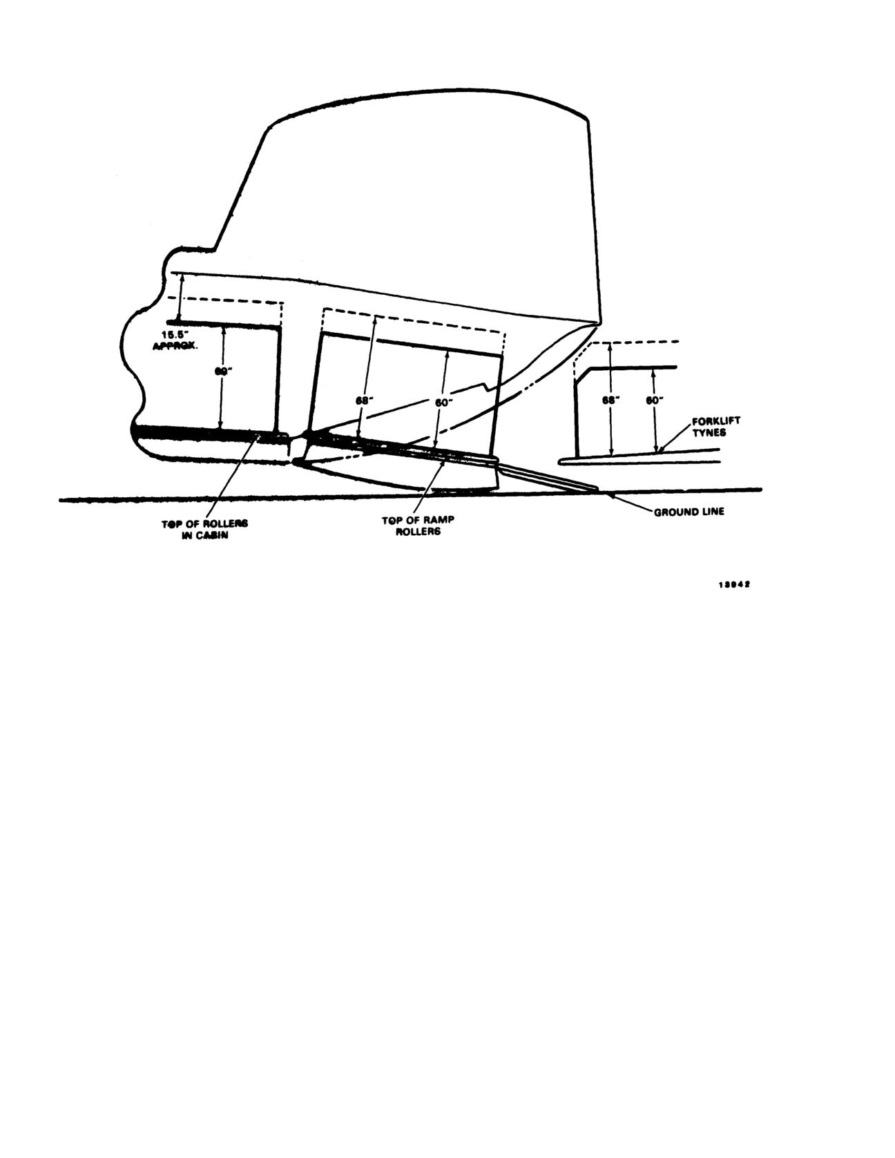
TM 55-1520-240-10
Figure 6-22. Loading With Ramp Down (Forklift Loading)
6-42
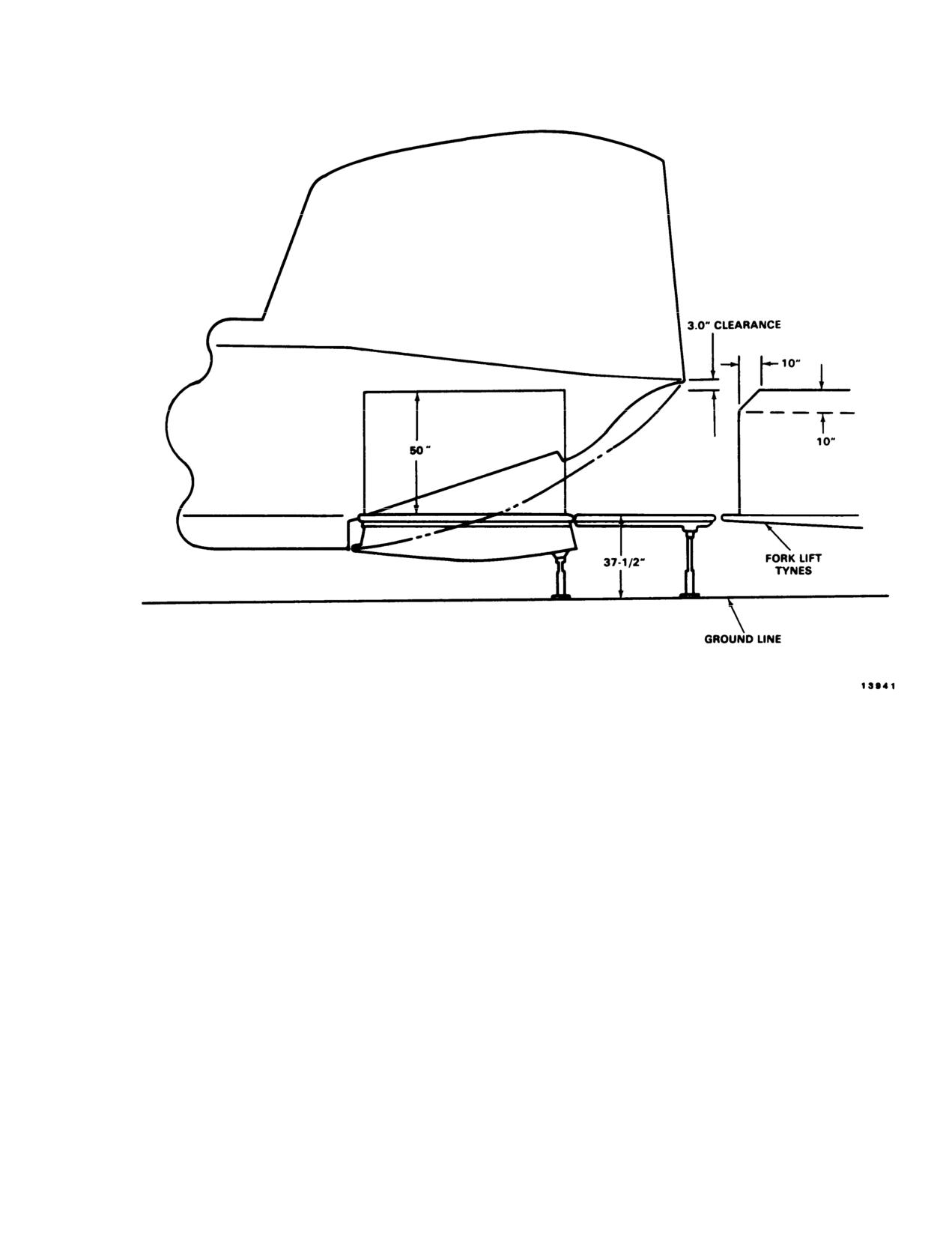
TM 55-1520-240-10
Figure 6-23. Loading With Ramp In Level Position
6-43
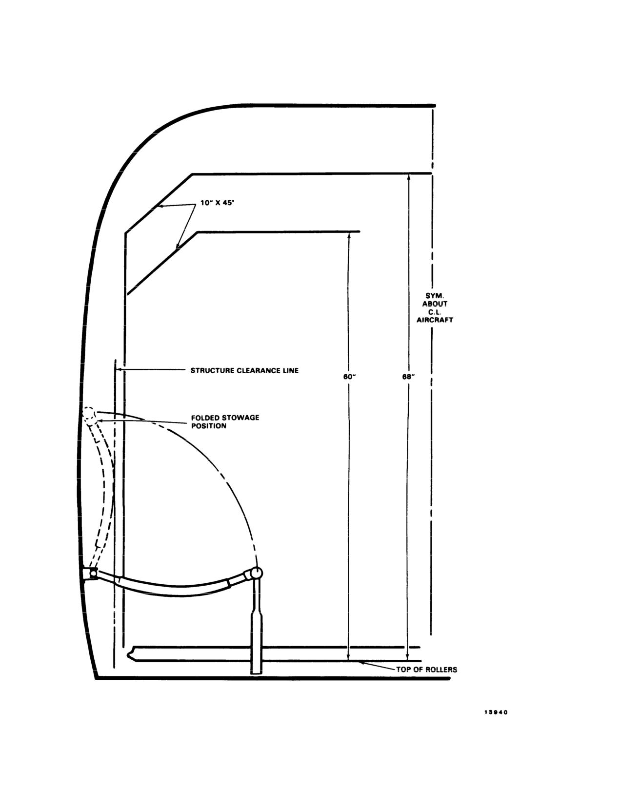
TM 55-1520-240-10
Figure 6-24. Load Clearances
6-44
TM 55-1520-240-10
SECTION Vll LOADING LIMITS
6-86. General.
The loading limits are depicted on figure 6-25. Using
loading techniques specified in this chapter, it would be
difficult to exceed these limits.
6-45
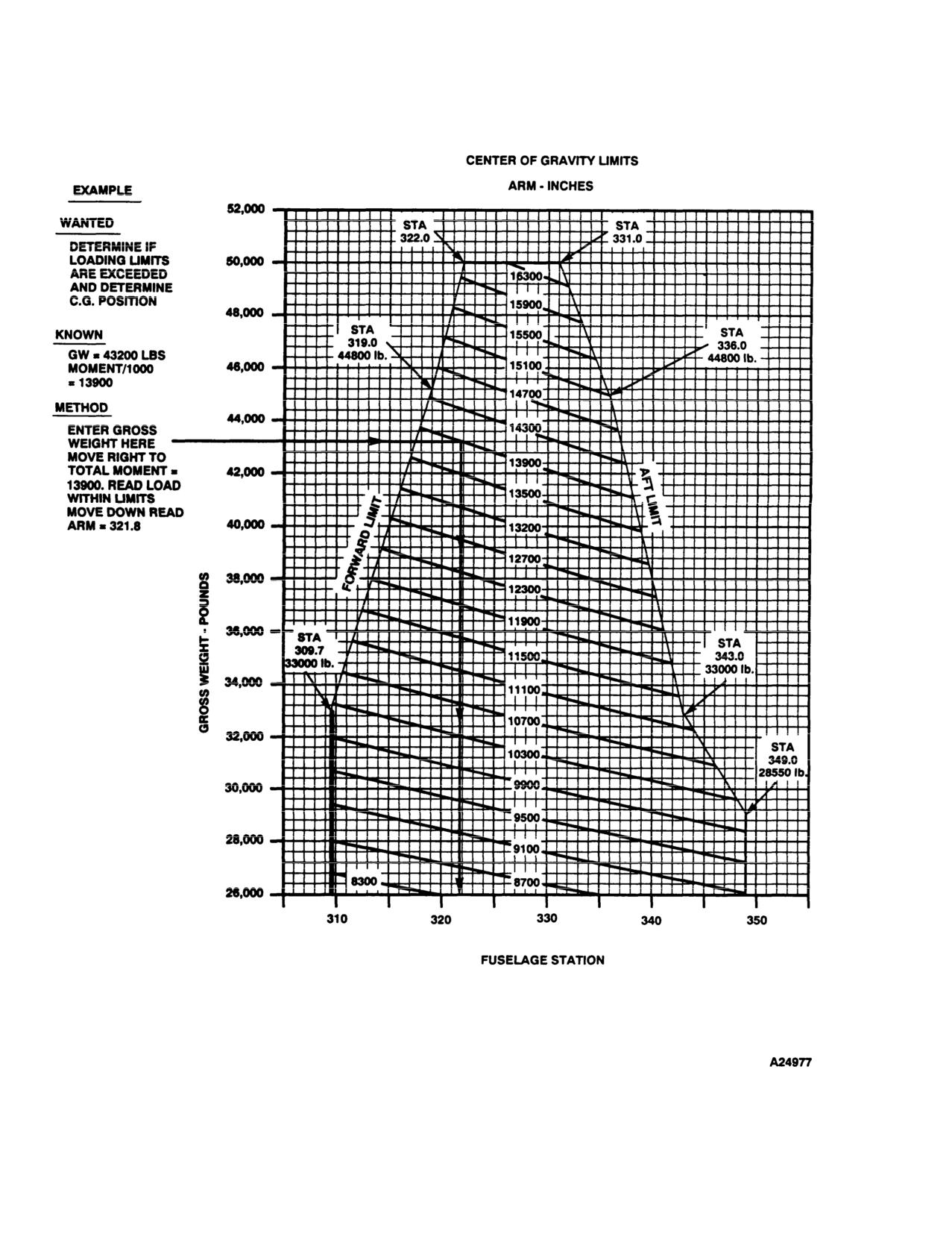
TM 55-1520-240-10
Figure 6-25. C.G. Limits Chart
6-46
TM 55-1520-240-10
CHAPTER 7
PERFORMANCE DATA
SECTION I INTRODUCTION
7-1. Purpose.
limits with an operating cruise guide indicator (CGI).
Airspeed limits with the CGI inoperative are in Chapter
The purpose of this chapter is to provide the best
5. If limits are exceeded, minimize the degree and time.
available performance data for the CH-47D helicopter.
Regular use of this information will enable you to
7-4. Use of Charts.
receive maximum safe utilization from the aircraft.
a. Chart Explanation.
The first page of each section
Although maximum performance is not always required,
regular use of this chapter is recommended for the
describes the chart(s) and explains its use.
following reasons.
b. The primary use of each chart is given in an
example and a guideline is provided to help you follow
a. Knowledge of your performance margin will allow
the route through the chart. The use of a straight edge
you to make better decisions when unexpected condi-
tions or alternate missions are encountered.
(ruler or page edge) and a hard fine point pencil is
recommended to avoid cumulative errors. The majority
b. Situations requiring maximum performance will be
of the charts provide a standard pattern for use as
more readily recognized.
follows: enter first variable on top left scale, move right
c. Familiarity with the data will allow performance to
to the second variable, deflect down at right angles to
be computed more easily and quickly.
the third variable, deflect left at right angles to the
fourth variable, deflect down, etc. until the final variable
d. Experience will be gained in accurately estimating
is read out at the final scale. In addition to the primary
the effects of variables for which data are not presented.
use, other uses of each chart are explained in the text
accompanying each set of performance charts.
7-2. General Data.
The data presented covers the maximum range of
NOTE
conditions and performance that can reasonably be
An example of an auxiliary use of the charts
expected. In each area of performance, the effects of
referenced above is as follows: Although the
altitude, temperature, gross weight (GW), and other
hover chart is primarily arranged to find
parameters relating to that phase of flight are pre-
torque required to hover, by entering torque
sented. In addition to the presented data, your judg-
available as torque required, maximum wheel
ment and experience will be necessary to accurately
height for hover can also be found. In gen-
obtain performance under a given set of circumstances.
eral, any single variable can be found if all
The conditions for the data are listed under the title of
others are known. Also, the tradeoffs be-
each chart. The effects of different conditions are
tween variables can be found. For example,
discussed in the text accompanying each phase of
at a given density altitude (DA) and pressure
performance. Where practical, data is presented at
altitude (PA), you can find the maximum
conservative conditions. However, NO GENERAL
GW capability as free air temperature (FAT)
CONSERVATISM HAS BEEN APPLIED. All perfor-
changes.
mance data presented is within the applicable limits of
the aircraft.
c. Dashed Line Data.
Data beyond conditions for
which tests were conducted, or for which estimates are
CAUTION
used, are shown as dashed lines.
Exceeding operating limits can-cause perma-
7-5. Data Basis.
nent damage to critical components. Over
limit operation can decrease performance,
The type of data used is indicated at the bottom of each
cause immediate failure, or failure on a
performance chart under DATA BASIS. The applica-
subsequent flight.
ble report and date of the data are also given. The data
provided generally is based on one of the following
categories.
7-3. Limits.
a. Flight Test Data.
Data obtained by flight test of
Applicable limit lines are shown on the charts. The
the aircraft by experienced flight test personnel at
dashed lines on the cruise charts are estimated airspeed
precise conditions using sensitive calibrated instruments.
7-1
TM 55-1520-240-10
b. Calculated Data. Data based on tests, but not on
7-7.2. ERFS II Tank Capacity.
flight test of the complete aircraft.
The capacity of the ERFS II tank using pressure refueling
c. Estimated Data. Data based on estimates using
is 805.5 US gallons. If filled using gravity refueling, the ca-
aerodynamic theory or other means but not verified by
pacity is 825.5 US gallons (In both cases 5.5 GALS will be
flight test.
unusable).
7-6.
Specific Conditions.
7-7.3. Amount of Unusable Fuel.
The data presented is accurate only for specific conditions
listed under the title of each chart. Variables for which data
The amount of unusable fuel in each of the ERFS II tanks
are not presented, but which may affect that phase of per-
is 5.5 US gallons of JP-8.
formance, are discussed in the text. Where data is avail-
able or reasonable estimates can be made, the amount
7-7.4. Fuel Transfer Rate.
that each variable affects performance will be given.
The rate at which fuel is transferred from the ERFS II
7-7.
General Conditions.
tanks to the helicopter main fuel tanks is 23 GPM.
In addition to the specific conditions, the following general
conditions are applicable to the performance data.
7-7.5. FARE Transfer Rate.
a. Rigging. All airframe and engine controls are as-
The FARE kit pump is rated at 120 GPM. However, the
sumed to be rigged within allowable tolerances.
configuration of the FARE fuel transfer hose assembly af-
b. Pilot Technique. Normal pilot technique is assumed.
fects this transfer rate. Pressure losses across couplings,
c. Aircraft Variation. Variations in performance be-
filters, and nozzles reduce the flow rate below the rated
tween individual aircraft are known to exist; however, they
value. The rate at which fuel is transferred from the ERFS
are considered to be small and cannot be accounted for
II tanks using the FARE pump and the standard configura-
individually.
tion of the FARE fuel transfer hose assembly is 84 to 88
GPM.
d. Instrument Variations. The data shown in the perfor-
mance charts does not allow for instrument inaccuracies
7-8.
Performance Discrepancies.
or malfunctions.
e. Airspeed Calibrations. The airspeed calibration
Regular use of this chapter will allow you to monitor instru-
ments and other aircraft systems for malfunction, by
chart presents the difference between indicated air speed
comparing actual performance with planned perfor-
(IAS), and calibrated airspeeds (CAS) for different flight
mance. Knowledge will also be gained concerning the ef-
conditions.
fects of variables for which data are not provided, thereby
f.
Except as noted, all data is for a clean configuration
increasing the accuracy of performance predictions.
(all doors installed, without armament).
g. Types of Fuel. All flight performance data is based on
7-9.
Definitions of Abbreviations.
JP-5 fuel. the change in fuel flow and torque available,
Capitalization and punctuation of abbreviations varies,
when using JP-4, JP-8, Aviation gasoline or any other ap-
depending upon the context in which they are used. In
proved fuels, is insignificant.
general, full capital letter abbreviations are used in text
7-7.1. ERFS II Performance Data.
material, charts and illustrations. Periods do not usually
Use of the performance data will enable the operator to re-
follow abbreviations; however, periods are used with ab-
ceive the maximum safe utilization of the ERFS II and
breviations that could be mistaken for whole words if the
FARE kit.
period were omitted.
7-2
Change 14
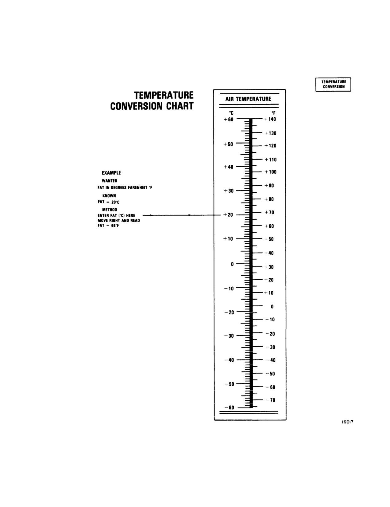
TM 55-1520-240-10
Figure 7-1. Temperature Conversion Chart
7-3
TM 55-1520-240-10
SECTION II EMERGENCY TORQUE AVAILABLE
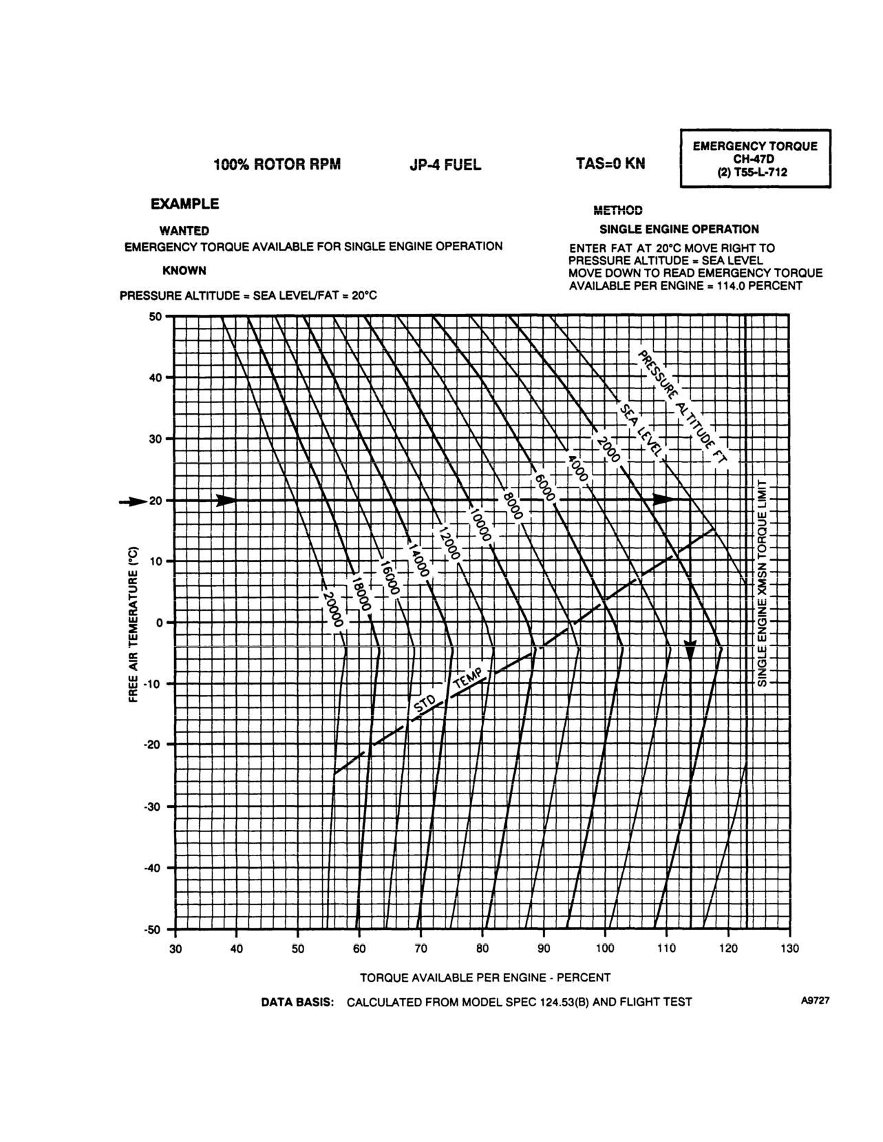
7-10. Emergency Torque Available.
temperature. To determine torque available, it is nec-
essary to know PA, and FAT. Enter the left side of the
Single engine emergency torque available may be ob-
tained from figure 7-2. Available torque is presented in
chart at known temperature, move right to known
terms of PA and FAT.
pressure altitude, then down to read torque available.
7-11. Use of Chart.
7-12. Conditions.
The primary use of the chart is to determine available
engine torque for various combinations of PA and
The chart is based on a rotor speed of 100%.
7-4
TM 55-1520-240-10
SINGLE ENGINE EMERGENCY TORQUE AVAILABLE
Figure 7-2. Emergency Torque Available
7-5
TM 55-1520-240-10
SECTION Ill MAXIMUM TORQUE AVAILABLE
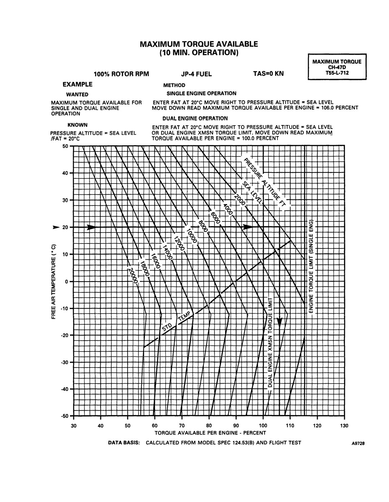
7-13. Maximum Torque Available (10-Minute Op-
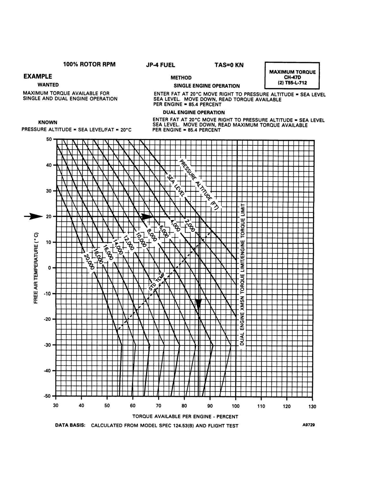
7-16. Maximum Torque Available (30-Minute Op-
eration).
eration).
Maximum torque available (l0-minute operation) may
Maximum torque available (30-minute operation) may
be obtained from figure 7-3. Available torque is pre-
be obtained from figure 7-4. Available torque is pre-
sented in terms of pressure altitude and free air tem-
sented in terms of PA and FAT.
perature.
7-17. Use of Chart.
7-14. Use of Chart.
The primary use of the chart is to determine available
The primary use of the chart is to determine available
engine torque for various combinations of PA and
engine torque for various combinations of pressure
temperature. To determine torque available, it is nec-
altitude and temperature. To determine torque avail-
essary to know pressure altitude and free air tempera-
able, it is necessary to know pressure altitude and free
ture. Enter the left side of the chart at the known
air temperature. Enter the left side of the chart at
pressure altitude, move right to known temperature,
known temperature, move right to known pressure
then down to read intermediate torque available.
altitude, then down to read torque available.
7-18. Conditions.
7-15. Conditions.
The chart is based on a rotor speed of 100%.
The chart is based on a rotor speed of 100%.
7-6
TM 55-1520-240-10
Figure 7-3. Maximum Torque Available (10-Minute Operation)
7-7
TM 55-1520-240-10
MAXIMUM TORQUE AVAlLABLE (30 MIN OPERATION)
Figure 7-4. Maximum Torque Available (30-Minute Operation)
7-8
TM 55-1520-240-10
7-9
TM 55-1520-240-10
SECTION IV CONTINUOUS TORQUE AVAILABLE
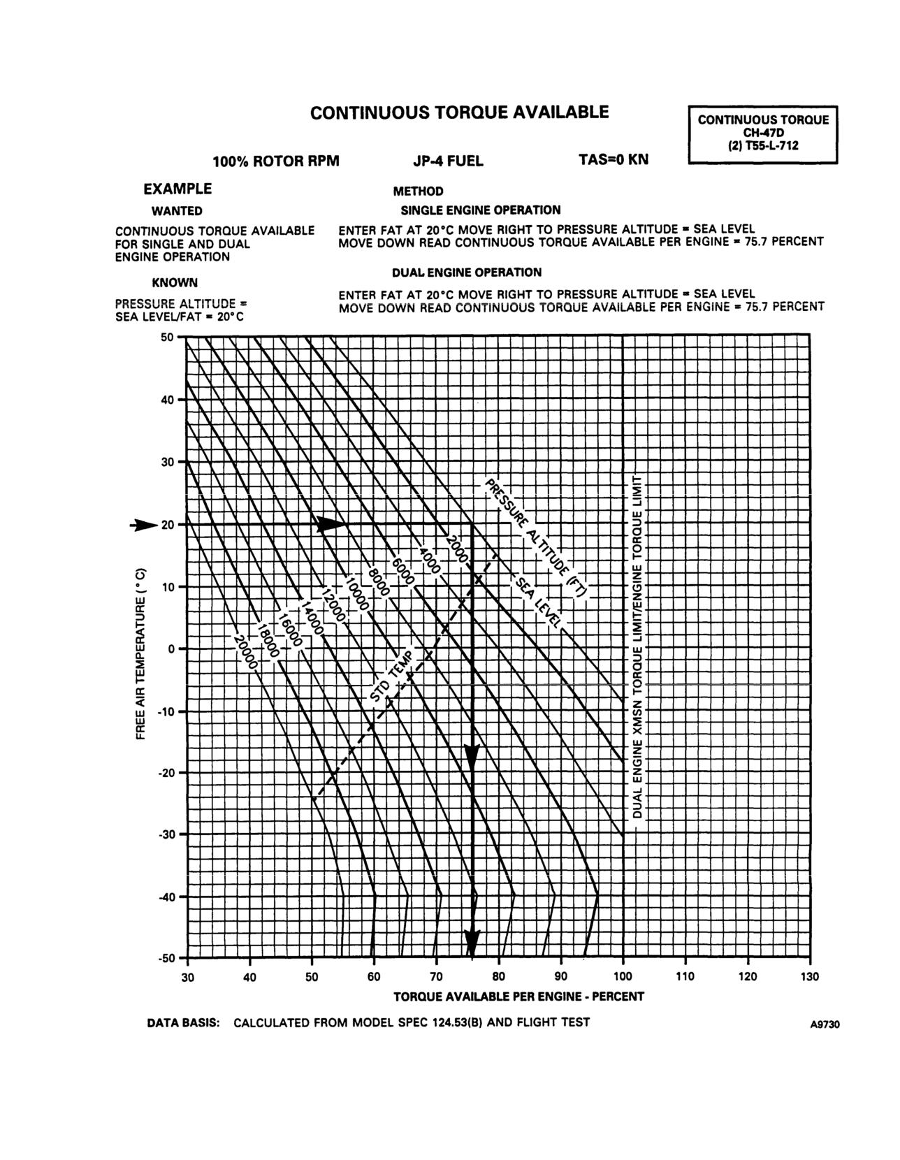
7-19. Continuous Torque Available.
temperature. To determine torque available, it is nec-
essary to know PA and FAT. Enter the left side of the
Continuous torque available may be obtained from
figure 7-5. Available torque is presented in terms of PA
chart at known temperature, move right to known
and FAT.
pressure altitude, then down to read torque available.
7-20. Use of Chart.
7-21. Conditions.
The primary use of the chart is to determine available
engine torque for various combinations of PA and
The chart is based on a rotor speed of 100%.
7-10
TM 55-1520-240-10
Figure 7-5. Continuous Torque Available
7-11
TM 55-1520-240-10
SECTION V HOVER
7-22. DESCRIPTION.
maximum torque available and read wheel height. This
wheel height is the maximum hover height,
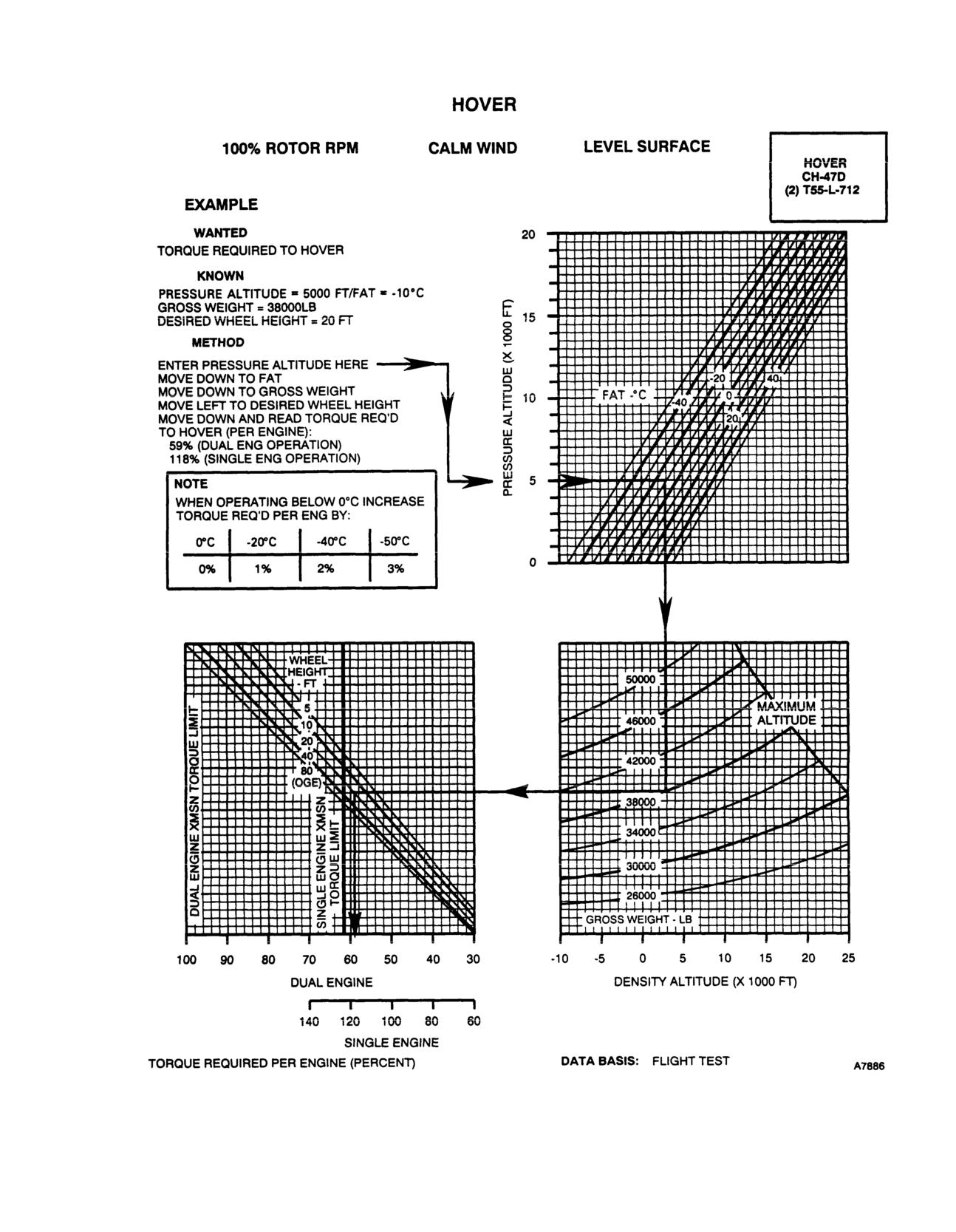
The hover chart, figure 7-6, presents torque required to
hover at 100% RRPM at various combinations of PA,
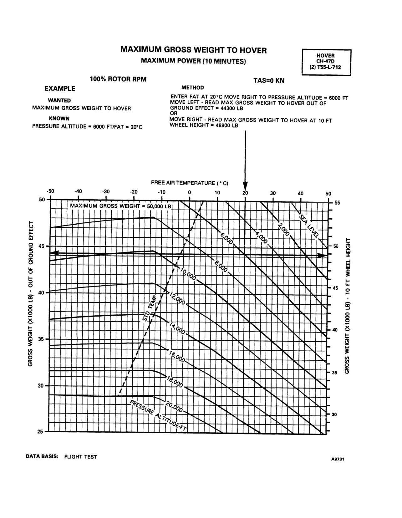
c. The hover charts may also be used to determine
FAT, GW, and wheel height for single and dual engine
maximum GW for hover at a given wheel height, PA,
operation.
and temperature. Enter at known pressure altitude,
move right to the FAT, then move down to the bottom
7-23. Use of Chart.
of the lower grid, and read density altitude. Now enter
a. The primary use of the charts is illustrated by the
lower left grid at maximum torque available. Move up to
wheel height, then move right to density altitude and
example. To determine the torque required to hover, it
read GW. This is the maximum gross weight at which
is necessary to know PA, FAT, GW, and desired wheel
height. Enter the upper right grid at the known pressure
the helicopter will hover.
altitude, move right to the temperature, move down to
7-24. Conditions.
gross weight. Move left to desired wheel height, deflect
down and read torque required for dual engine or single
a. The hover chart is based on calm wind, level
engine operation.
surface, and 100% RRPM.
b. In addition to the primary use, the hover ceiling
b. Hover in ground effect (HIGE) data is based on
charts (fig. 7-7) may be used to predict maximum hover
hovering over a level surface. For normal transition
height. This information is necessary for use of the
from hover to forward flight, the minimum hover wheel
takeoff chart found in figure 7-8. To determine maxi-
height should be
10 feet to prevent ground contact. If
mum hover height, it is necessary to know PA, FAT,
helicopter is to hover over a surface known to be steep,
GW, and maximum torque available. Enter at the
covered with vegetation, or if type of terrain is unknown,
known pressure altitude, move right to FAT, move
the flight should be planned for hover out of ground
down to gross weight, move left to intersection with
effect (HOGE) capability.
7-12
TM 55-1520-240-10
Figure 7-6. Hover Chart
7-13
TM 55-1520-240-10
Figure 7-7. Hover Ceiling
7-14
TM 55-1520-240-10
7-15
TM 55-1520-240-10
SECTION VI
TAKEOFF
7-25. Description.
required obstacle height, move right to desired true
climbout airspeed, then down and read distance re-
The takeoff chart, figure 7-8, defines distances required
quired to clear obstacle.
to clear obstacles of
50 feet, 100 feet, 150 feet, and
200
feet based upon maximum hover height capability and
b. A hover check should be made prior to takeoff to
true airspeed. The procedure for takeoff is the level
verify hover capability. If winds are present, hover
flight acceleration technique.
capability will be greater than predicted since the hover
chart is based on calm wind conditions.
NOTE
7-27. Conditions.
The maximum hover heights shown are in-
dicative of helicopter performance capability
a. The takeoff chart is based on calm wind conditions.
and do not imply that this hover height must
Since the surface wind velocity and direction cannot be
be maintained through takeoff.
accurately predicted, all takeoff planning should be
based on calm air conditions. Takeoff into the wind will
improve takeoff performance.
7-26. Use of Chart.
The primary use of he chart is illustrated by the
examples.
A tailwind during takeoff and climbout will
increase the distance for obstacle clearance
a. To determine the distance required to clear an
and may prevent a successful takeoff.
obstacle, it is necessary to know maximum hover height
(hover capability), obstacle height, and climbout true
airspeed. Calculation of maximum hover height is de-
b. Takeoff performance data are based on the use of
scribed in Section V, Hover. Enter the chart for the
maximum torque available at 100% RRPM.
7-16
TM 55-1520-240-10
CHAPTER 8
NORMAL PROCEDURES
SECTION I MISSION PLANNING
8-1. Mission Planning.
(7) Visually inspects engine and ramp area for
proper operation.
Mission planning begins when the mission is assigned
and extends to the preflight check of the helicopter. It
(8) Remove chocks and closes ramp door when
includes, but is not limited to, checks of operating limits
called for by the pilots.
and restrictions, weight/balance and loading, perfor-
(9) Observes and gives clearance to pilots during
mance, publications, flight plan, and crew briefings. The
taxi and hover operation. Reports any object or condi-
pilot in command shall ensure compliance with the
tion which would pose a hazard to the helicopter. When
contents of this manual that are applicable to the
the helicopter is being taxied in obstructed areas, the
mission.
flight engineer or other crewmembers may be required
8-2. Aviation Life Support Equipment (ALSE). All
to act as taxi director or blade watchers. Taxi directors
aviation life support equipment required for mission,
and blade watchers must be familiar with CH-47 ground
turning characteristics (fig. 2-3 and 8-l).
e.g., helmets, gloves, survival vests, survival kits, etc.,
shall be checked.
(10) Perform check of ramp area and MAINTE-
NANCE PANEL every 30 minutes of flight.
8-3. Crew Duties/Responsibilities. The minimum
crew required to fly the helicopter is a pilot, copilot, and
8-4. Crew Briefing. A crew briefing shall be con-
flight engineer. Additional crewmembers, as required,
ducted to ensure a thorough understanding of individ-
may be added at the discretion of the commander. The
ual and team responsibilities. The briefing should in-
manner in which each crewmember performs his related
clude, but not be limited to, copilot, mission equipment
duties is the responsibility of the pilot in command.
operator, and ground crew responsibilities and the
a. Pilot. The pilot in command is responsible for all
coordination necessary to complete the mission in the
aspects of mission planning, preflight, and operation of
most efficient manner. A review of visual signals is
the helicopter. He will assign duties and functions to all
desirable when ground guides do not have a direct voice
communications link with the crew.
other crewmembers as required. Prior to or during
preflight, the pilot will brief the crew on the mission,
8-5. Passenger Briefing. The following is a guide
performance data, monitoring of instruments, commu-
that should be used in accomplishing required passen-
nications, emergency procedures, and armament proce-
ger briefings. Items that do not pertain to a specific
dures.
mission may be omitted.
b. Copilot. The copilot must be familiar with the
a. Crew introduction.
pilot’s duties and the duties of the other crew positions.
The copilot will assist the pilot as directed.
b. Equipment.
c. Flight Engineer.
The flight engineer will perform
(1) Personal to include ID tags.
all duties as assigned by the pilot in addition to the
(2) Professional.
following specific duties:
(1) Performs or coordinates maintenance, servic-
(3) Survival.
ing, inspection, loading, and security of the helicopter.
c. Flight Data.
(2) Checks that log book is current and correct.
(1) Route.
(3) Accompanies pilot during preflight inspec-
(2) Altitude.
tion; performs the inspection with the pilot.
(3) Time en route.
(4) Checks the security of each area inspected.
(4) Weather.
(5) Assists in seating and securing passengers;
checks load security.
d. Normal Procedures.
(6) Ensures the helicopter is clear during all
(1) Entry and exit of helicopter.
starting procedures and informs the pilots of any objects
(2) Seating.
which would pose a hazard to the helicopter during all
phases of ground operation.
(3) Seat belts.
8-1
TM 55-1520-240-10
(4) Movement in helicopter.
(12) Parachutes.
(5) Internal communications.
(13) Ear protection.
(6) Security of equipment.
(14) ALSE.
(7) Smoking.
e. Emergency Procedures.
(8) Oxygen.
(1) Emergency exits.
(9) Refueling.
(2) Emergency equipment.
(10) Weapons.
(3) Emergency landing/ditching procedures.
(11) Protective masks.
8-2
TM 55-1520-240-10
SECTION II
OPERATING PROCEDURES AND MANEUVERS
8-6. Operating Procedures And Maneuvers.
safe helicopter operation are included. The preflight may
be made as comprehensive as conditions warrant at the
This section deals with normal procedures and includes
discretion of the pilot.
all steps necessary to ensure safe and efficient operation
of the helicopter from the time a preflight begins until the
8-11. Before Exterior Check.
flight is completed and the helicopter is parked and se-
*1. Publications-Check DA Forms 2408-12, -13,
cured. Unique feel, characteristics, and reaction of the he-
-14, -18, DD Form 365-4, and DD Form 1896, lo-
licopter during various phases of operation and the tech-
cally required forms and publications, and avail-
niques and procedures used for hovering, takeoff, climb,
ability of operator’s manual (-10), and checklist
etc., are described, including precautions to be observed.
(-CL).
Your flying experience is recognized; therefore, basic
*2. Ignition lock switch-On.
flight principles are avoided. Only the duties of the mini-
mum crew necessary for the actual operation of the heli-
3.
712
EMERGENCY POWER panel-Check trip
copter are included.
indicators and timers.
8-7. Mission Equipment Checks. Mission equipment
4.
712
Topping stops-Check stowed.
checks are contained in Chapter
4, MISSION
5. Cockpit area-Check as follows:
EQUIPMENT. Descriptions of functions, operations, and
effects of controls are covered in Section III, FLIGHT
a. General condition.
CHARACTERISTICS, and are repeated in this section
b. Fire extinguisher-Check seal intact, DD
only when required for emphasis. Checks that must be
Form 1574/1574-1, and security.
performed under adverse environmental conditions,
such as desert and cold weather operations, supplement
c. Jettisonable door release handles/latches.
normal procedures checks in this section and are
d. Sliding windows.
covered in Section IV, ADVERSE ENVIRONMENTAL
*6. Forward transmission-Check oil level, filter but-
CONDITIONS.
ton, and oil cooler condition.
8-8. Symbols Definitions. The checklist includes items
that may not be checked by the flight engineer and that
7. Fuel sample-Check before first flight of the day.
may or may not be installed. These items are annotated
8-12. INTERIOR CHECK.
immediately preceding the check to which they are
8-13. Forward Cabin.
pertinent: F for flight engineer, and 0 to indicate a
requirement if the equipment is installed. The symbol L
1. Flight control closet-Check ILCA actuators for
indicated that a detailed procedure for the step is located
extended jam buttons and thrust idler assem-
in the detailed procedures section of the condensed
blies for bent cracked arms. Check ILCA con-
checklist. When a helicopter is flown on a mission
necting link for cracks or displaced bearings.
requiring intermediate stops, it is not necessary to
2. Heater compartment-Check security of compo-
perform all of the normal checks. The steps that are
nents and winch.
essential for safe helicopter operations on intermediate
3. Emergency escape ax-Check condition and se-
stops are designated as “through flight” checks. An
curity.
asterisk* indicates that performance of steps is
mandatory for all “through-flights” when there has been
4. Cabin door-Check condition and security.
no change in pilot-in-command. The asterisk applies only
5. Avionics equipment-Check security of compo-
to checks performed prior to takeoff. Duties performed by
nents and connections. Determine whether both
individual in copilot station are indicated by a circle
pilots displacement gyros are installed.
around the step number, i.e., 4. Step numbers with no
circles around them may be performed by the aviator in
6. Fire extinguisher-Check seal intact, DD Form
either pilot or copilot’s seat.
1574/1574-1, and security.
8-9. Checklist. Normal procedures are given primarily in
7. Cabin escape panel-Check condition and secu-
checklist form and amplified as necessary in
rity.
accompanying paragraph form when a detailed
8. Transformer-rectifier air intake screens-Check
description of a procedure or maneuver is required. A
both clear. A transformer-rectifier may fail if rags
condensed version of the amplified checklist, omitting all
or other items stowed behind troop seats block
explanatory text, is contained in the Operators and
the air intakes.
Crewmembers Checklist, TM 55-1520-240-CL.
9. Seats, litters, first aid kits, cargo and jettisonable
8-10. Preflight Check. The pilot’s walk-around and
cabin window-Check condition and security.
interior checks are outlined in the following procedures.
The preflight check is not intended to be a detailed
10. Utility hatch door and lower rescue door-Check
mechanical inspection. The steps that are essential for
condition and position as required.
Change 14
8-3
TM 55-1520-240-10
11. Center cargo hook - Check condition and
f. Single Point Pressure Refueling Hose As-
position as required. Check 2,100 psi charge,
sembly - Check connection security;
manual release mechanisms stowed, manual
Unisex valve at ERFS II Tank CLOSE.
release mechanism for proper cam position
g. Electrical Harness - Check connection
and latched.
security of J1.
h. Fuel Quantity Sensing Wiring Harness -
CAUTION
Check connection security of J2.
i. Fuel/Defuel Vent Valve - Check in the
Do not lift or rotate the center cargo hook
into the cabin area or allow the mid hook
CLOSED position.
to lay on the cargo floor or access door
panel during inspection or use. The exces-
WARNING
sive tension placed on the triple emergen-
cy release cable housing assembly may
Failure to remove water and contaminants
partially dislodge the housing and engage
from the ERFS II tank sump could result in
or activate the forward and aft hook emer-
contaminants being transferred to the he-
gency release mechanism. This may
licopter fuel tanks or other aircraft or
cause an inadvertent release of loaded
equipment during FARE operations. If wa-
forward and aft hook assemblies in flight.
ter and contaminants are not removed, a
12. Forward and aft cargo hook release lever -
loss of engine power may result.
Check for security and stowed.
j.
ERFS II Tank Sump Fuel Sample -
O
13. Forward, center, and aft cargo hook release
Check before first flight of the day.
lever - Check for security and stowed.
k.
Filler Cap - Check in place, closed, and
locked.
13.1
714A
DECU - Check condition and secu-
l.
ERFS II FUEL CONTROL PANEL -
rity.
Check or set as follows:
O
14. ERFS installed - Check the following:
(a)
Electrical Harness-Helicopter Re-
a. All fuel manifold lines, electrical lines,
ceptacles to Fuel Control Panel -
grounding cables, and vent lines to ensure
Check connection security of J5.
that they are properly secured and con-
(b)
Electrical Harness-Fuel Control
nected.
Panel to Tank Assembly - Check
b. Fuel manifold lines and tiedown straps for
connection security of J1, J2, and J3.
chafing. Tank tiedown straps for security.
(c)
Wiring Harness-Fuel Quantity Sen-
c. Ensure ERFS tanks are properly fueled,
sing - Check connection security of
580 GALLONS MAXIMUM PER TANK.
J4.
d. ERFS tanks for leakage.
(d)
PUMP AC circuit breaker six (6)
LO
14.1
ERFS II installed - For each installed ERFS
each - Check in reset position on
II tank assembly check the following:
TANK 1, TANK 2, and TANK 3 (if
a. Tank Restraint Assembly - Check loca-
installed).
tion and security.
(e)
PANEL POWER circuit breaker -
b. Cavity Overboard Drain - Check connec-
Check in reset position.
tion and security of drain in use. Check
drain not in use is capped.
(f)
PANEL LIGHTING circuit breaker -
Check in reset position.
c. Grounding Cable - Check connection
security.
(g)
PUMP switches - OFF on TANK 1,
d. Vent Hose Assembly - Check connec-
TANK 2, and TANK 3.
tion security.
(h)
PRESS LOW lights three (3) each -
e. Fuel Transfer Hose Assembly - Check
Press to test (Aircraft power must be
connection security; all Unisex valves
on to illuminate).
OPEN.
(i)
REFUEL VALVE - Check CLOSE.
CAUTION
(j)
PANEL illumination switch/rheostat
- OFF.
Failure to close the Unisex valves at the
ERFS II tank end of the single point pres-
(k)
FUEL QUANTITY switch - Set to 1,
sure refueling hose assembly could allow
2, 3, and TOTAL to check fuel quanti-
suctioning of fuel from the helicopter main
ty in each tank (Aircraft power must
fuel tanks during FARE operations.
be on to illuminate).
8-4
Change 18
TM 55-1520-240-10
8-14. Aft Cabin.
* 7. APU start accumulators - Check pressures.
If pressure is less than 3,000 psi, pressurize
1. Ramp - Check.
the system with the hand pump before at-
2. Engine fire extinguisher bottles - Check.
tempting to start the APU.
3. POWER STEERING MODULE - Check
* 8. MAINTENANCE PANEL Check for tripped bite
pressure.
indicators and hydraulic fluid levels.
4. FUEL VALVE #2 ENGINE - Check OPEN.
O
8.1
AFT POS LIGHT switch - Set as required.
5. FUEL VALVE CROSSFEED (right)
-
CLOSED.
O
9. PWR MDL CHIP BURN-OFF - Check for
condition and security.
6. HYD SYS FILL module - Check condition,
fluid level, cover secure, and valve closed.
* 10. Aft transmission - Check as follows:
Change 18
8-4.1/(8-4.2 blank)
TM 55-1520-240-10
a. Oil level.
5. Pressure refueling control panel-Check as fol-
lows:
b. Filter button.
a. PWR and LT switches at OFF.
c. Oil cooler.
b. Refueling receptacle cover installed and se-
d. Secure doors.
cured.
11. APU-Check.
c. Landing gear and pressure refueling panel
12. EMERGENCY APU FLUID SHUT OFF VALVE
cover closed and secure.
-Check OPEN.
6. Static port-Check unobstructed.
13. COMPASS FLUX VALVE-Check.
7. Right electrical compartment-Check condition
14. FUEL VALVE CROSSFEED (left)-Check
and security.
CLOSED.
8-18. Forward Cabin.
15. FUEL VALVE #1 ENGINE-Check OPEN.
1. Heater intake, exhaust, and combustor drain
-Check.
16. Fire extinguisher-Check seal intact, DD Form
1574/1574-1 and security.
2. Pilot’s jettisonable door-Check.
8-15. EXTERIOR CHECK.
3. Pilot’s pedal area-Check.
8-16. Aft Cabin.
4. Right AFCS yaw ports-Check.
1. Position light-Check condition.
5. Pitot tubes-Check.
1.1
714A
DECU-Check condition and security.
6. Antennas-Check.
2. Right aft landing gear area-Check condition and
7. Searchlights-Check.
security of all components as follows:
8. Windshield and wipers-Check.
a. Gear support structure.
9. Left AFCS yaw ports-Check.
b. Tire.
10. Copilot’s pedal area-Check.
c. Shock strut extension and static lock stowed.
11. Copilot’s jettisonable door-Check.
d. Power steering actuator and brakes.
8-19. Left Cabin.
e. Fluid lines.
1. Fuselage-Check as other items are checked.
f. Electrical wiring.
2. Left electrical compartment-Check.
g. Ground proximity switch and linkage.
3. Forward landing gear area-Check condition and
security of all components as follows:
h. Swivel lock.
a. Tires.
3. Vent and fluid drain lines-Check unobstructed.
b. Shock strut for extension.
3.1
ERFS II Installed. Aircraft Overboard Drain Out-
c. Brakes.
lets-Check. Check for signs of any fuel seep-
age.
d. Fluid lines.
3.2
ERFS II Installed. Aircraft Overboard Vent Out-
4. Forward and aft cargo hooks-Check hooks clear
lets-Check. Check for signs of excessive fuel
and load beam closed. Electrical harness and re-
venting.
lease cable connected and dust caps stowed. If
8-17. Right Cabin.
hook not installed, check for dust caps on the
electrical and release cable receptacles.
1. Fuselage-Check as other items are checked.
5. Lower anti-collision light-Check condition.
*2. Fuel system-Check as required, caps secured.
6. Static port-Check unobstructed.
3. Position light-Check condition.
*7. Fuel system-Check as required, caps secure.
4. Forward landing gear area-Check condition and
7.1
714A
Engine wash system connectors-Check
security of all components as follows:
condition and security.
a. Tire.
8. Left aft landing gear area-Check condition and
b. Shock strut for extension.
security of all components as follows:
c. Brakes.
a. Gear support structure.
d. Fluid lines.
b. Tire.
Change 14
8-5
TM 55-1520-240-10
c. Shock strut extension and static lock stowed.
*13. Forward rotor (right side)-Check same as aft ro-
tor.
d. Static ground wire contacting the ground.
14.
Forward transmission oil cooler inlet-Check for
e. Fluid lines.
obstructions.
f. Electrical wiring.
15.
Upper boost actuators-Check for extended jam
g. Ground proximity switch and linkage.
indicators and exposed pistons for cleanliness.
h. Brakes.
16.
Forward transmission-Check for foreign objects
i. Swivel lock.
and cooler condition.
9. Vent and fluid drain lines-Check unobstructed.
H 17. Hydraulic compartment-Check as follows:
8-20
Top of Fuselage.
a. Condition and security of lines and coolers.
*1.
No. 2 engine-Check as follows:
b. No. 1 flight control system accumulator for
a. Inlet for foreign objects. Check condition and
proper indication.
security of FOD screens.
*18. Forward rotor (left side)-Check same as aft ro-
b. Oil level and cap secure.
tor.
c. Cowling for security.
19. Brake accumulator pressure-Check 600 to 1400
d. Tailpipe condition and security, presence of
psi.
fuel, oil, and foreign objects.
*20. Pylon fairings, work platforms, and inspection
2.
Anticollision light and formation lights-Check
panels-Check secure.
condition.
21. Top of fuselage-Check for foreign objects.
*3.
Aft rotor (right side)-Check blades for condition
and reservoir oil levels.
CAUTION
O 4.
Droop stop shrouds-Check condition and securi-
Failure to remove fuel vent covers may cause
ty. Check inspection cover closed.
fuel tanks to collapse while in use under
5.
Upper boost actuator-Check for extended jam
certain conditions.
indicators and exposed piston rods for cleanli-
O 22. Remove the fuel vent covers (3) (if installed)
ness.
before using ERFS.
H 6.
Hydraulic compartment-Check as follows:
*8-21
Walk Around Check and Security Brief.
a. Condition and security of lines and coolers.
1.
All access doors-Check secure.
b. No. 2 flight control system accumulator for
proper indication.
2.
Tie down, locking devices, covers, and ground
cables-Removed and secured.
c. Utility reservoir pressurization accumulator for
2500 to 3500 psi charge.
3.
Cockpit, fwd transmission, and fwd cabin area
*7.
Combining transmission area-Check for foreign
soundproofing installed-Check.
objects, and oil coolers for obstructions. Check
NOTE
filter buttons for engines and combining trans-
The cockpit, forward transmission, flight con-
mission.
trol, and avionics compartment soundproofing
*8.
Aft rotor (left side)-Check blades for condition
should be installed during normal aircraft op-
and reservoir oil levels.
eration to reduce noise levels in the crew and
passenger areas and to aid in venting of trans-
O 9.
Droop stop shrouds-Check condition and securi-
mission heat and fumes.
ty.
4.
Crew/passenger briefing-Complete as required.
10.
Upper boost actuator-Check for extended jam
indicators and exposed pistons for cleanliness.
8-22
Before Starting Engines.
*11.
No. 1 engine-Check same as No. 2 engine.
1.
Pedal adjustment-Matched. Check that yaw
12.
Drive shaft area-Check condition and security
pedals are adjusted equally and that adjustment
as follows:
pins are in the same hole position. Uneven pedal
adjustment can cause droop stop pounding dur-
a. Drive shafts, couplings, and mounts.
ing engine start and ground operations.
b. Fluid lines.
2.
Shoulder harness locks-Check operation and
c. Control linkage.
leave unlocked.
d. Foreign objects.
*3.
No. 1 and No. 2 PDPs-Check all circuit breakers
e. Drive shaft fairing.
in and gang bar up.
8-6
Change 14
TM 55-1520-240-10
H 4. Overhead switches and control panels. Set as
r. HYD switches-Set as follows:
follows:
(1) PWR XFER switches-OFF.
*a.
EXT LTG switches-As required.
(2) FLT CONTR switch-BOTH.
*b.
CPLT LTG switches-As required.
(3) BRK STEER switch-ON. Cover down.
c.
COMPASS switch-As required.
d.
TROOP WARN switches-OFF.
(4) RAMP switch-ON.
e.
HTG switches-As required.
(5) RAMP EMER switch-HOLD. Cover
down.
f.
W/S WIPER switch-OFF.
g.
ELECT switches-OFF.
5.
FIRE PULL handles-In.
*h.
LTG switches-As required.
6.
AGENT DISCH switch-Check.
*i.
FUEL CONTR switches-Set as follows:
*7.
XMSN OIL PRESS switch-SCAN.
(1) XFEED switch-OPEN.
*8.
XMSN OIL TEMP switch-SCAN.
(2) REFUEL STA switch-OFF.
*9.
VGI switches-NORM.
(3) L MAIN FUEL PUMP switches-ON.
10.
CYCLIC TRIM switch-AUTO.
(4) All remaining FUEL PUMP switches -
*11. AFCS SYSTEM SEL switch-OFF.
OFF.
*12.
FLARE DISP switch-SAFE.
j.
712
START switches-OFF.
k.
ENG COND levers-STOP.
13.
Avionics equipment-OFF; set as required.
*l.
714A
FADEC switches-Check or set as
O 13.1
HUD-OFF.
follows:
14.
712
EMERG ENG TRIM switches-AUTO;
(1) B/U PWR switch-OFF.
covers down.
(2) LOAD SHARE switch-TRQ.
15.
SWIVEL switch-LOCK.
(3)
1 and 2 PRI/REV switches-PRI.
8-23
Starting Engines.
(4) NR% switch-100.
*
1.
BATT switch-ON.
*m.
INTR LTG switches-As required.
2.
CAUTION LT TEST switch-TEST. Check that all
*n.
PLT LTG switches-As required.
caution capsules and the two master caution
o.
ANTI-ICE switches-OFF.
lights on the instrument panel come on. Some of
p.
HOIST switches-OFF.
the caution capsules will be on before the system
is checked.
q.
CARGO HOOK switches-Set as follows:
3.
Clocks-Running, Set as required.
(1) MSTR switch-OFF.
(2) HOOK SEL switch-As required.
F
4.
TROOP WARN ALARM and JUMP LT-Two
bells, two red, two green.
(3) EMERG REL ALL switch-OFF. Cover
down.
*F 5.
Fire guard posted-APU clear to start.
Change 14
8-6.1/(8-6.2 blank)
TM 55-1520-240-10
* 6. APU-Start as follows:
*
17. Fuel quantity-Check as required.
a. APU switch-RUN for 3 to 5 seconds.
*
18. Cyclic trim indicators-Check GND position.
b. APU switch -START for 2 seconds, then RUN.
*F 19. Rotor blades-Check position. Make sure that a
rotor blade is not within 30° of the centerline of
NOTE
the fuselage throughout control check.
If the start is not completed, or the APU is
*
20. AFCS SYSTEM SEL switch-Check as follows:
automatically shut down, wait one minute for
cooling before attempting a restart. Failure to
a. Select individual system and check opposite
allow the APU to cool may cause a premature
AFCS caution capsule remains on.
shutdown on restart due to overtemperature. If
b. Select BOTH and check both AFCS caution
the start is not completed, do not turn the BATT
capsules go out.
switch OFF. Set the APU switch to OFF, check
c. AFCS SYSTEM SEL switch-OFF.
the BITE indicators on the ESU, and record the
display for maintenance.
*
21. Flight control travel and hydraulics-Check as
follows:
c. APU ON indicating light-Check on.
a. Check each individual flight control hydraulic
d. UTIL HYD SYS caution - Check out. If the
light does not go out within 30 seconds after
system. Check each flight control axis individu-
APU ON indicating light comes on, APU switch
ally and in combination with other axes through
OFF.
full travel for smoothness of motion.
*
7. APU GEN switch-ON. NO. 1 and 2 RECT
b. Check for corresponding movement of the fore
OFF and L and R FUEL PRESS caution capsules
and aft rotors.
out.
CAUTION
NOTE
If either HYD FLT CONTR caution capsule
If helicopter is parked on a slope greater than
does not go out in 30 seconds after the PWR
4°, longitudinal stick travel may be restricted
XFER switches are set to ON, set PWR
to less than 7 inches forward (up slope) or 4
XFER switch to OFF. Do not fly the helicopter.
inches aft (down slope).
*
8. PWR XFER-Check
a. PWR XFER 1 and 2 switches- ON. Check
c. Check caution capsules as this check is being
HYD FLT CONTR caution capsules out.
performed. If the flight controls are moved
F b. Pressures normal.
erratically during the control check, unusual
vibrations may be felt.
*F 9. MAINTENANCE PANEL-Check.
d. Check cyclic for freedom of movements in all
a. GND switch-TEST, then RESET.
quadrants. Check for a minimum of 7 inches
O b. GROUND CONTACT indicating lights-
forward and 4 inches aft travel.
check on.
e. Check thrust and pedals individually through
c. Systems-Normal.
full travel for freedom of movement.
* 10. Avionics-On as desired.
f. FLT CONTR switch-BOTH.
O 10.1 HUD-ON
g. Position the cyclic and pedals at neutral, thrust
*
11. CARGO HOOKS HOIST/WINCH-Check op-
at ground detent.
eration as required. Refer to Chapter 4, Section
*
21.1
714A
DECU PRESTART BIT-Perform as
III.
follows:
12. SLT-FIL switches-Check and set as required.
a. B/U PWR switch-ON.
*
13. PARKING BRAKE-Set.
b. Wait until ENG FAIL caution lights go out.
14. CRUISE GUIDE indicator-Check for pointer
c. ENG COND levers-GND.
in white test band when the CGI TEST switch is
at FWD and AFT TEST.
F
d. DECUs-Check displays read 88.
* 15. Altimeters-Set and check as follows:
21.2 AN/ASN 149 (V) GPS-STARTUP and config-
ure.
a. Barometric altimeter-Set and check.
22.
Avionics-Perform operational check and set as
b. Radar altimeter-ON and set.
required.
16. FIRE DETR switch-TEST. Check fire warning
23.
712
ENGINE BEEP TRIM switch (NO. 1 &
lights on, release switch, and check fire warning
lights out.
2)-DECREASE for 8 seconds.
Change 13
8-7
TM 55-1520-240-10
26.1
714A
P3 bellow-Check as follows:
*F
24. Area-Clear for start.
a. ENG 1 FADEC PRI-REV switch (started eng-
gine )-REV
b. FADES Caution-ON
CAUTION
c. N1-Maximum change +3%.
The flight controls must be manned any time
d. FADEC PRI-REV switch (started engine)-
the helicopter is on the ground with rotors
PRI.
turning.
e. FADEC FAIL Caution-OUT.
f. Repeat for ENG 2.
NOTE
*
27. Transmission oil pressures-Check for mini-
mum of 7 psi. There is no time limit for ground
Either engine may be started first.
idle operation, provided there is a minimum of 7
*
25.
712
First engine-Start as follows:
psi oil pressure in each engine transmis-
F a. Clear for start.
sion.
b. L and R FUEL PRESS LIGHTS-Check out.
c. ENG COND lever-STOP.
CAUTION
d. ENG START switch-MTR.
Failure of either engine to accelerate smoothly
NOTE
from ground to flight may be an indication of
a clutch malfunction in the engine transmis-
If engine does not reach 15% but exceeds 10%
sion.
N1 (minimum) and has reached it's maximum
speed, initiate start, but monitor engine and
*
28. ENG COND levers-FLT. No. 1 and No.2 clear
PTIT for possible hung start and/or excessive
to FLT. Engine acceleration should be smooth
PTIT.
with no surging.
e. Motor engine to a minimum of 15% N1. Set
ENG COND lever-GND; ENG START
switch to START immediately.
CAUTION
f. Release START switch to MTR before PTIT
reaches 200°C. When N1 is 50%, set START
Failure of either engine N1 to accelerate past
switch to OFF. Check STARTER ON light out.
70% N1 may be an indication of a clutch
malfunction in the engine transmission.
g. Engine instruments-Check when stabilized at
ground idle (N1 at 60 to 63%). Check engine oil
*
29. 712
RPRM-Set as required.
pressure for 20 psi minimum. The engine should
accelerate to ground idle speed within 45 sec-
onds.
NOTE
Delay turning second generator on or off for
CAUTION
two seconds. This delay will give DECU time to
sample power without causing soft fault.
The N2 section of the second engine starts
turning when the first engine is started;
*
30. GEN 1 and 2 switches-ON.
712
No. 1 & 2
however, the lubrication system of the second
GEN OFF
714A
GEN 1 & 2 caution capsules
engine is driven by the N1 sections which does
out.
not begin to turn until the start sequence is
*
31. APU GEN switch-OFF.
initiated. Delay in starting the second engine
will result in excessive wear on the N2 bear-
*
31.1.
714A
DECU START BIT-Perform as follows:
ing package and seal. Start the second engine
a. ENG COND levers-Retard 5 degrees.
within three minutes of the first.
F
b. DECU display-Check display reads 88.
*
25.1.
714A
First engine-Start as follows.
a. ENG START switch-Select engine to be
NOTE
started and hold until N1 accelerates to 10%,
If DECU display is other than 88, shutdown
then release switch.
engine being checked and remove all power to
b. Engine should accelerate to ground idle (50 to
DECU by pulling the respective Engine PRI and
59%) within 45 seconds.
REV CONT circuit breakers on the PDP. Reset
c. Transmission oil pressures-Check increasing.
the circuit breakers and repeat the engine start
sequence and DECU fault monitoring check. If
d. Engine oil pressure-Check 5 psi minimum.
*
26. Second Engine-Start by using the same method
DECU display is other then 88 once again, shut
as first engine.
down helicopter and refer to maintenance.
8-8
Change 13
TM 55-1520-240-10
c. ENG COND levers - FLT.
crease then release. Torque and N1
should return to normal settings.
* 32. PWR XFER 1 and 2 switches - OFF.
b. EMERG ENG TRIM 2 switch - Check
same as No. 1 engine.
* 33. APU switch - OFF. APU ON caution capsule
out.
L 6.1
714A
FADEC Reversionary system
-
* 34. Systems - Check normal.
Check (First flight of day).
a. FADEC 1 and 2 PRI-REV switches - PRI.
* 35. Transponder - STBY.
b. NR% switch - 100%.
8-24. Engine Ground Operation.
c. FADEC 1 -Check as follows:
L 1. FUEL PUMP and XFEED - Check operation
(1) FADEC 1 PRI-REV switch - REV.
as follows:
(2) FADEC 1 INC-DEC switch - DEC.
a. All FUEL PUMP switches - OFF. Check
Check for decrease in No. 1 engine
L and R FUEL PRESS caution capsules
N1 and torque, and corresponding
should come on.
increase in No. 2 engine N1 and
torque.
b. L AFT MAIN FUEL PUMP switch - ON.
Check L and R FUEL PRESS caution cap-
(3) FADEC 1 INC-DEC switch - INC.
sule should go out. Then switch OFF.
Check for increase in No. 1 engine
N1 and torque, and corresponding
c. Remaining MAIN FUEL PUMP switches
decrease in No. 2 engine N1 and
- Check as in step b. above.
torque.
d. L AFT AUX FUEL PUMP switch - ON.
(4) FADEC 1 PRI-REV switch - PRI.
Check L AUX PRESS light on overhead
f. Repeat check for FADEC 2.
panel comes on, then goes out. Set pump
switch to OFF.
7. Radar altimeters - Check IAW paragraph
2-200.
e. Remaining three AUX FUEL PUMPs -
Check as in step d, except check R AUX
8. Transponder - Check and set.
PRESS light on, then off, for R AUX FUEL
9. Navigation Set DGNS - Perform operational
PUMP switches.
check, confirm waypoint entry and SAS/AS as
required.
*
2.
FUEL CONTR switches - Set as follows:
*8-25. Before Taxi.
a. All FUEL PUMP switches - ON.
F
b. XFEED switch CLOSE
- XFEEDS
WARNING
checked closed, light out.
Personnel injury or death may occur and
3.
VGI switches - As required.
damage to airframe and rotor systems will
4.
ANTI-ICE systems - Check as required.
occur if the forward or aft rotor head rotor
blade droop stop(s) are missing or inter-
F
a. PITOT switch - ON. Physically check for
poser block(s) on the aft rotor head are not
pitot tube and yaw port heat. Then switch
engaged. After engine run-up and before
OFF.
flight, or shutdown if flight is not con-
ducted, the flight engineer will scan the
b. W/S switches - ON. Physically check for
ground in the immediate area of the air-
windshield heat. Then switch OFF.
craft for evidence of detached droop
*
5.
Flight instruments - Check as follows:
stops.
a. HSI compass cards - Check synchro-
CAUTION
nized. Crosscheck with magnetic com-
pass. Refer to Chapter 3, Section III.
To prevent damage to the cargo hooks and
structure, do not ground taxi over rough
b. Attitude indicators - Adjust as required.
or uneven terrain with the forward and aft
cargo hooks installed.
6.
712
Emergency engine trim system
-
Check as follows:
1. SWIVEL switch - As required.
a. EMERG ENG TRIM 1 switch - DECR
momentarily. Check torque and N1 de-
2. AFCS switch - As required.
Change 17
8-9
TM
55-1520-240-10
NOTES:
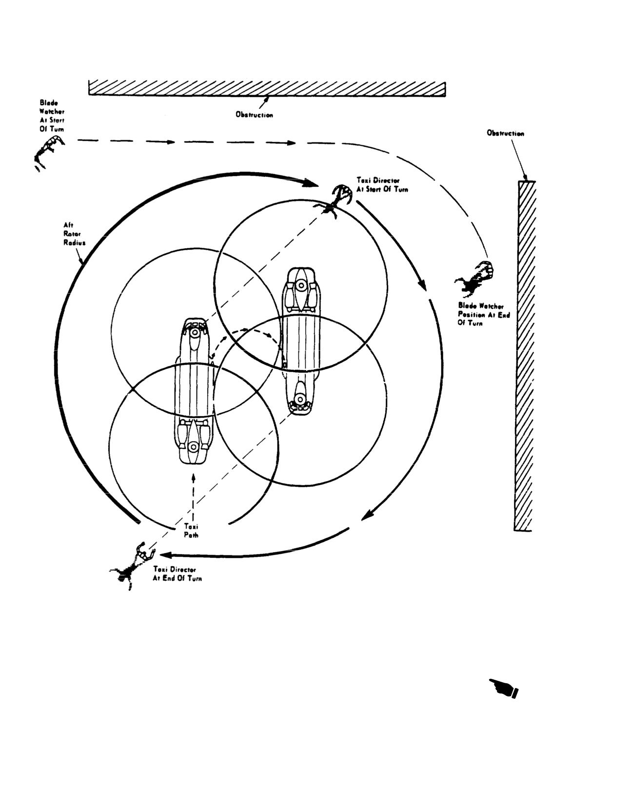
1. AVOID TURNING OR MANEUVERING NEAR
DIRECTORS AND BLADE WATCHERS FAMILIAR WITH
OBSTRUCTIONS WHEN LESS THAN 75 FEET WILCH-47 TURNING CHARACTERISTICS.
EXIST BETWEEN CENTERLINE OF THE HELICOPTER
3. THE BLADE WATCHER SHALL POSITION HIMSELF
AND THE OBSTRUCTIONS.
SO HE HAS A CLEAR VIEW OF THE ROTOR BLADES
2. IF NECESSARY TO TAXI WHEN LESS THAN 7AND ANY OBSTRUCTIONS. AND THE TAXI DIRECTOR.
CLEARANCE EXISTS BETWEEN THE CENTERL
4. USE STANDARD HAND SIGNALS. REFER TO
THE HELICOPTER AND OBSTRUCTION, USE
TAXI
1-1500-204-24.
A73437
Figure
Taxi Director and Blade Watcher Positions
8-10
Change 13
TM 55-1520-240-10
3. Cyclic trim indicators - Check GND position.
*8-26. Taxiing. Refer to TC 1-216 Aircrew Training
Manual, (ATM).
3.1 HUD - Adjust brightness, mode, barometric
altitude, pitch, and roll as necessary.
1. Brakes - Check pilot’s and copilot’s as re-
quired.
FO
4. Flare dispenser safety pin - Remove and
2. Power steering - Check as required.
stow.
F
5. Chocks - Removed and secured.
8-27. Before Hover.
* 1. SWIVEL switch - LOCK.
F
6. Ramp and cabin door - As required.
* 2. AFCS control panel - Set as follows:
F
7. Crew, passengers, and mission equipment -
Check ready for taxi.
a. AFCS SYSTEM SEL switch - BOTH.
b. CYCLIC TRIM switch - AUTO.
F
8. Taxi director and blade watchers - Positioned
as required (fig. 8-1).
3.
712
Health Indicator Test (HIT) check. Per-
9. PARKING BRAKE - As required.
form as required.
Change 17
8-10.1/(8-10.2 blank)
TM 55-1520-240-10
NOTE
8-29. Before Takeoff.
The PAC check may be deferred to the hover
1. Systems - Check indications of the following:
check.
a. Rotor - Check as required.
3.1
714A
Power Assurance Check (PAC) - Per-
b. Torque.
form first flight of day:
c. Engine.
a. NR% switch - 100%.
d. Transmission.
b. ENG 1 ENG COND lever - Adjust.
e. Fuel.
c. THRUST CONT lever - Raise until TRQ reads
60% to 80%. Stabilize for 30 seconds.
f.
712
Master caution panel.
F d. TEST switch ENG 2 - PWR ASSURANCE.
g.
714A
Caution/Advisory panel.
Check DECU display. Compare displayed value
2. PARKING BRAKE As required.
with PAT Trigger Value.
3. AFCS SYSTEM SEL switch - As required.
e. ENG 1 ENG COND lever - FLT.
4. CYCLIC TRIM switch - Check.
f. Repeat check with ENG 2 ENG COND lever.
5. SWIVEL switch - LOCK.
g. THRUST CONT lever - Adjust.
6. Transponder- As required.
*
4. RRPM - Set as required.
F
7. Crew, passengers, and mission equipment
8-28. Hover Check. Perform the following check at a
- Check.
hover:
8-30. Normal Takeoff. Refer to TC 1-216 Aircrew
1. Flight controls - Check flight controls for cor
Training Manual (ATM).
rect response.
8-31. Hover Refer to TC 1-216 Aircrew Training Manual
2. Systems instruments - Check normal.
(ATM).
3. Flight instruments - Check as required.
To engage radar altitude hold perform the following:
_________
a. VSI, barometric and radar altimeters - indicate
WARNING
climb and descent.
b. Turn pointers, heading indicators and magnetic
Do not use radar altitude hold in forward
compass-Indicate turns right and left.
flight over terrain. It may not provide ad-
c. Slip indicator - Ball free in race.
equate terrain clearance in rapidly changing
d. Attitude indicator - Indicate nose high, nose
terrain. Use radar altitude hold to maintain a
low, banks left and right.
constant absolute altitude during hover or
forward flight over water. RAD ALT hold
can be used to a maximum of 1,500 feet
absolute altitude.
NOTE
a. Radar altimeter - ON. Check that pointer has
Rapid rotation of the pitch and roll trim knobs
rotated from behind the mask, the digital display
on the attitude indicator may cause abrupt pitch
is lit, and the OFF flag is out of view.
and roll attitude changes with AFCS on.
b. Fly to desired altitude.
e. Airspeed indicator - Check.
c. RAD ALT select on AFCS panel - Press. Check
FO 4. GROUND CONTACT indicating lights check
ENGAGED light ON. The radar altitude hold
-Both off.
feature of the AFCS will maintain a constant
5. AFCS - Check as follows: (First flight of day).
altitude.
a. SYSTEM SEL switch - NO. 1. Check helicop-
d. To select another altitude press the THRUST
ter stable with no abrupt engagement error.
CONT BRAKE TRIGGER. Fly to desired alti
Check NO. 2 AFCS OFF caution on.
tude and release the THRUST CONT BRAKE
b. SYSTEM SEL switch --NO. 2. Check helicop-
TRIGGER. The altitude at the moment the
trigger is released will be the new altitude.
ter stable with no abrupt engagement error.
Check NO. 1 AFCS OFF caution on.
Takeoff over water. Takeoff over water is begun from a
c. SYSTEM SEL switch - Both. Check helicop-
hover height of approximately 30 feet.
ter stabled with no abrupt engagement error.
Align the helicopter with the desired takeoff course at a
Check both AFCS OFF caution capsules extin-
stabilized hover of approximately 30 feet, or an altitude
guished.
permitting safe obstacle clearance. Smoothly apply forward
6. Power - Check. Note torque and N1.
cyclic pressure to level the helicopter and begin acceleration
Change 13
8-11
TM 55-1520-240-10
into effective translational lift (ETL). Control rate of accel-
8-35. Cruise Check.
eration and direction of flight with cyclic and altitude with
1. Fuel Consumption - Check.
thrust. As the aircraft accelerates through ETL, establish a
2. HDG select - As required. Perform the follow-
pitch attitude and apply thrust that will result in a simulta-
ing:
neous gain in altitude and airspeed. Continuous coordinated
a. Rotate HDG knob on the HSI that is to be used
application of control pressures is necessary to maintain
for the referenced heading until the cursor (bug)
rim, heading, flight path, airspeed, and rate of climb.
is aligned with chosen heading.
8-32. Maximum Performance Takeoff. A takeoff that
b. Trim helicopter straight and level (center ball on
demands maximum performance from the aircraft may be
turn and slip indicator) and trim forces (depress
necessary because of various combinations of heavy aircraft
CENTERING DEVICE RELEASE).
loads, restricted performance due to high density altitudes,
barriers that must be cleared, and other terrain features. The
c. CMD SEL switch on HSI MODE SELECT
decision to use either of the following takeoff techniques
panel - Press. Check switch is depressed and
must be based on an evaluation of the conditions and
SEL legend is lit.
aircraft performance.
d. AFCS HDG - Press. Check ENGAGED light
a. Coordinated Climb Takeoff. Align the helicopter with
on. The helicopter will now turn to and capture
he chosen takeoff course at a stabilized hover of approxi-
the heading.
mately 10 feet. Apply forward cyclic pressure smoothly and
e. Heading can be changed by rotating the cursor
gradually while simultaneously increasing thrust to begin a
(bug) to the new heading. The helicopter will
coordinated acceleration and climb. The climb may be made
then turn to the new heading.
vertical with appropriate adjustment of the cyclic control.
f. Cabin door escape panel - Assure that airspeed
Maximum torque available should be applied as the aircraft
is less than 100 KIAS before closing door in
attitude is established that will permit safe obstacle clear-
flight.
ance. The climbout is continued at that attitude and power
NOTE
setting until the obstacle is cleared. After the obstacle is
cleared, adjust aircraft attitude and thrust as required to
Pressing either CENTERING DEVICE RE-
establish a climb at the desired rate and airspeed. Continu-
LEASE switch disengages heading select op-
ous coordinated application of control pressures is neces-
erations
sary to maintain trim, heading, flight path, airspeed, and rate
of climb. Takeoff may be made from the ground by
CAUTION
positioning the cyclic control in neutral, prior to increasing
thrust. Takeoff over water is begun from a hover height of
Radar altitude (RAD ALT) hold can only be
approximately 30 feet and continued as above.
used in forward flight overwater, it cannot be
used in forward flight over terrain.
b. Level Acceleration Takeoff. Align the helicopter with
the chosen takeoff course at a stabilized hover of approxi-
CAUTION
mately 10 feet. Apply forward cyclic pressure smoothly and
gradually while simultaneously increasing thrust to begin
Large pitch inputs will result in rapid gain or
accelerating at approximately 10 feet. Maximum torque
loss of altitude. If altitude hold is on, an
available should be applied prior to accelerating through
over-torque condition can occur during large
ETL. Adjust cyclic stick to maintain desired pitch attitude
pitch-down inputs. Monitor thrust control
throughout acceleration to climb airspeed. Approximately 5
movement and torquemeter during airspeed
knots prior to reaching the selected climb airspeed, gradu-
changes. Also, when operating with altitude
ally release forward cyclic pressure and allow the aircraft to
hold, limit bank angles to 45 degrees maxi-
begin a constant airspeed climb to clear the obstacle. Care
mum. An excessive bank angle may result in
must be taken not to decrease airspeed during the climbout
an altitude loss, and if operating at a high
since this may result in the helicopter descending (falling
through). After the obstacle is cleared, adjust aircraft atti-
gross weight, an overtorque condition.
tude and thrust as required to establish a climb at the desired
3. BARO/RAD altitude hold - As required. Alti-
rate and airspeed. Continuous coordinated application of
tude hold is selected to hold a constant altitude.
control pressures is necessary to maintain trim, heading,
a. When at chosen cruise altitude and airspeed,
flight path, airspeed, and rate of climb. Takeoff may be
press BARO (RAD) ALT switch on AFCS
made from the ground by positioning the cyclic control in
control panel. Check that ENGAGED light is
neutral prior to increasing thrust.
ON. The helicopter will now maintain the se-
Takeoff over water is begun from a hover height of
lected altitude.
approximately 30 feet and continued as above.
b. To change altitude, press the THRUST CONT
8-33.
Slingload.
BRAKE TRIGGER. Fly the helicopter to the
Refer To TC 1-2 16 Aircrew Training Manual (ATM).
desired altitude, then release the THRUST
8-34.
Climb.
CONT BRAKE TRIGGER. The helicopter will
Refer to chapter 7 for recommended airspeeds, power
remain at the altitude at which the trigger was
settings, and fuel flow.
released.
8-12
Change 13
TM 55-1520-240-10
F
4. Ramp area - The ramp area must be checked
not vary significantly because of GW or CG. As observed
every 30 minutes of flight. (Refer to section I,
from the cockpit, the water level will appear to intersect the
Crew Duties.)
fuselage below the lower nose enclosure.
8-36. DESCENT.
8-40. Running Landing to Water. Running landings
Refer to Chapter 7 for power requirements at selected
can be performed within the limitations shown in chapter 5.,
airspeeds and rates of descent.
but should only be performed during training missions,
actual single-engine conditions when a hovering approach is
8-37.
Before Landing.
not possible, or when atmospheric conditions dictate. Run-
The following checks must be accomplished prior to land-
ning landings for training should only be performed to calm
ing
water (Sea State 1 or less).
1. Systems - Check indications of the following:
Prior to performing a running landing to the water, the
a. Rotor.
PITOT HEAT switch must be ON. The ramp, lower half of
b. Torque.
cabin door, lower rescue door, and drain plugs must be
closed. Landing/searchlights shall be retracted. The ap-
c. Engine.
proach is shallow, and flown at an airspeed that provides
d. Transmission.
safe aircraft control. Prior to water entry, it may be
e. Fuel.
necessary to use the windshield wipers. Entry of the aft
f.
712
Master caution panel.
wheels into the water is easily recognized because the
g.
714A
Caution/Advisory Panel.
helicopter will decelerate noticeably. Touchdown attitude
2. PARKING BRAKE - As required.
should be held constant until the apparent water speed has
3. AFCS control panel - Check as follows:
decreased below 10 knots. At or below 10 knots, the nose
can be lowered to the water by lowering the thrust control
a. AFCS HDG and ALT switches as required.
rod and neutralizing the cyclic stick. A 4- to 5-knot forward
b. CYLIC TRIM switch as required.
speed will result when the helicopter is level and the
c. AFCS selector switch as required.
controls are neutralized with the thrust control at the ground
F
4. Crew, passengers, and mission equipment-
detent.
Check.
NOTE
8-38. LANDING.
Aft landing gear ground proximity switches are
Refer to FC1-2l6, Aircrew Training Manual (ATM).
not actuated during a water landing. Therefore,
longitudinal cyclic pitch actuators must be
8-39. Landing From a Hover to Water. Prior to
manually set to ground position.
landing, the PITOT HEAT switch must be ON. The ramp,
lower half cabin door, lower rescue door, and drain plugs
When the helicopter is in the water, two-way communica -
must be closed. Landing/searchlights shall be retracted.
tion is lost on system whose antennas are submerged. The
From a stabilized hover, decrease thrust for a smooth rate of
HF radio can be operated.
descent. A vertical descent, rather than a descent with some
8-41. After Landing.
forward movement, will tend to disperse the swirling water
1. AFCS SYSTEM SEL switch - As required.
spray under a no-wind condition. As the aft wheels and then
2. SWIVEL switch - As required.
the fuselage near the water, continue to lower, the thrust
control to ground detent. As more of the fuselage enters the
3. Transponder - As required.
water, buoyancy will level the helicopter attitude.
4. ANTI-ICE switches - OFF.
FO
5. GROUND CONTACT lights check - both on.
NOTE
6. Cyclic trim indicators - Check GND indication.
Aft landing gear ground proximity switches are
not actuated during a water landing. Therefore,
8-42. Engine Shutdown.
longitudinal cyclic pitch actuators must be
manually set to ground position.
CAUTION
CAUTION
Critical flight control components can be
damaged if thrust is not in ground detent.
If contact is made with floating debris, re-
turn to hover and assess damage.
1. Flight Controls - Neutralize. Position the pedals
and cyclic at neutral and the thrust at the ground
As the attitude approaches level, the helicopter will start
detent. Start 2 minutes engine cool-down run
moving forward and stabilize at approximately 4 to 5 knots.
when the THRUST CONT lever is in the detent
This speed will be attained with the controls in neutral and
position and the engine temperatures have stabi-
the thrust control at the ground detent. The water level will
lized.
Change 13
8-13
TM 55-1520-240-10
2. PARKING BRAKE - Set.
serve the rotor tip path of the forward and
aft rotor heads. A rotor blade drooping
3. HTG switches - OFF.
significantly lower than the other blades
indicates a missing droop stop. In this
4. SLT-FIL switches - OFF and stow as required.
case the remaining running engine’s ECL
should be advanced until sufficient rotor
5. AFCS SYSTEM SEL switch - OFF.
RPM is achieved to lift rotor blades off the
stops to insure no blade contact with air-
F
6. Ramp - As required.
frame and maintenance is contacted to
F
7. Wheels - Chocked.
prepare aircraft for an emergency shut-
down that will minimize damage to the air-
F
8. Mission equipment - Safe as required.
craft and injury to personnel.
F
9. Fire guard - Posted.
NOTE
L 10. APU - Start. For APU starting procedures,
Aft landing gear ground proximity switches
refer to paragraph 8-23.
are not actuated during a water landing.
Therefore, longitudinal cyclic pitch actuators
11. APU GEN switch - ON.
must be manually set to ground position prior
to engine shutdown on the water.
12. GEN 1 and 2 switches - OFF.
13. PWR XFER 1 and 2 switches - ON.
15. ENG COND levers - GND, run engines at
GND for 2 minutes.
14. Cyclic trim indicators - Check GND position,
manually program if necessary.
16. FUEL CONTR switches - Set as follows:
a. XFEED switch - CLOSE.
WARNING
b. FUEL PUMP switches - OFF.
c. REFUEL STA switch - As required.
Personnel injury or death may occur and
damage to the airframe and rotor systems
will occur if the forward or aft rotor head
rotor blade droop stop(s) are missing or
WARNING
interposer block(s) on the aft rotor head
are not engaged. After engine run-up and
Personnel injury or death may occur and
before flight, or shut down if flight is not
damage to the airframe and rotor systems
conducted, the flight engineer will scan
will occur if the forward or aft rotor head
the ground in the immediate area of the
rotor blade droop stop(s) are missing or
aircraft for evidence of detached droop
the interposer blocks on the aft rotor head
stops. Prior to moving engine condition
are not engaged. Prior to moving engine
levers (ECL) from ground to stop, flight
condition levers (ECL) from ground to
engineer will, to the best extent possible,
stop, the flight engineer will, to the best
determine if the interposer blocks on the
extent possible, determine if the interpos-
aft rotor head are in position and that all
er blocks on the aft rotor head are in posi-
forward and aft droop stops are attached.
tion and that all forward and aft droop
If an interposer block or droop stop are not
stops are attached. If an interposer block
in place, the flight engineer will notify the
or droop stop is not in place, the flight
pilot in command. All non-crewmembers
engineer will notify the pilot in command.
will evacuate aircraft to a safe location. If
If interposer blocks appear to be in place
possible, crew will contact maintenance
and no droop stops missing, the flight en-
and attempt to engage interposer block
gineer will clear the pilot to shut down the
with high pressure water stream or pre-
first engine. After the first engine is shut
pare aircraft for shutdown in such a way
down, the flight engineer will observe the
as to minimize damage to aircraft and
rotor tip path of the forward and aft rotor
components and prevent injury to person-
heads. A rotor blade drooping significant-
nel. If interposer blocks appear to be in
ly lower than the other blades indicates a
place and no droop stops are missing, the
missing droop stop.
flight engineer will clear the pilot to shut-
down the first engine. After the first engine
is shut down, the flight engineer will ob-
17. ENG COND levers - STOP.
8-14
Change 17