OPERATOR’S MANUAL FOR ARMY CH-47D HELICOPTER (EIC: RCD, 2003) - page 14
TM 1-1520-240-10
NOTE
4. AUX FUEL PUMP switch - ON (each aux
tank with fuel remaining).
LCT and DASH actuators will remain pro-
grammed at the airspeed at which the gener-
If AUX PRESS indicating light remains on:
ators were turned off. Normal engine trim is
disabled when generators are turned off.
5. AUX FUEL PUMP switch(es) (inoperative
pump(s)) - OFF. Monitor FUEL QUANTITY
2. GEN 1 and 2 switches - OFF.
indicator for the affected tank.
3. Land as soon as possible.
6. AUX FUEL PUMP switche(es) - ON for
After landing:
operative pumps or OFF for inoperative
pumps.
4. EMER ENG SHUTDOWN.
5. BATT switch - OFF.
9-1-51. Fuel venting
9-1-48. Smoke and Fume Elimination.
Fuel venting from either main tank vent indicates a possi-
bility of fuel cell overpressurization. Should venting oc-
1. Airspeed - Above 60 KIAS.
cur:
2. Pilot’s sliding window - Open.
1. AUX FUEL PUMP switches (affected
side) - OFF.
3. Helicopter attitude -Yaw left, one half to
one ball width on turn and slip indicator.
2. Main tank (affected side) - Monitor.
4. Upper half of main cabin door - Open.
When 1,000 pounds of fuel remain:
O 5. RAMP EMER switch - As required.
3. AUX FUEL PUMP switches - ON. (monitor
NOTE
fuel quantity).
The combination of steps 2, 3, and 4 effective-
When tanks quantity reaches 1,600 pounds:
ly evacuates the cockpit and forward cabin of
smoke and fumes at airspeeds above 60
4. AUX FUEL PUMP switches - OFF.
KIAS. Opening the cargo loading ramp evac-
5. Steps 2 through 4 - Repeat until
uates the main cabin. With items in steps 2, 4,
auxiliary tanks are empty.
and 5 opened, intensification of a smoldering
fire may occur. If the source of the fire cannot
9-1-52. L or R FUEL PRESS Caution.
be determined, close the cargo loading ramp
but keep the pilot’s windows and the upper
If both main tank fuel pumps fail, fuel will be drawn from
half of the main cabin door open. This will
the main tanks as long as the helicopter is operated
allow the pilots to see the instrument panels
below 6,000 feet pressure altitude. If the L or R FUEL
and outside references for landing.
PRESS caution comes on:
6. Cargo loading ramp - As required.
1. XFEED switch - OPEN (above 6,000 feet
7. Copilot’s sliding window - Closed.
PA).
8. NVG curtain - Open (if applicable).
2. FUEL PUMP (S) circuit breakers - Check in.
9-1-49. Fuel System.
Pump(s) are operational - Proceed with step 3.
9-1-50. Aux Fuel Pump Failure.
Pumps are not operational - Proceed with step 4.
An auxiliary fuel pump failure will be indicated by an AUX
3. XFEED switch - CLOSED.
PRESS indicating light, on the FUEL CONTROL panel,
4. FUEL PUMP switches - OFF (inoperative
illuminating and /or the fuel quantity in the affected tank
pump(s).
remaining at the same level. Should this occur, proceed
as follows:
9-1-53. Fuel Low Caution.
1. FUEL QUANTITY selector switch - Check.
If the FUEL LOW and FUEL PRESS cautions come on
If one or both auxiliary fuel tanks have fuel remaining:
perform the following:
2. AC-DC FUEL PUMP circuit breakers
-
1. Fuel quantity - Check individual tanks.
Check in.
2. XFEED switch - As required.
3. FWD and AFT AUX FUEL PUMP switches
affected side) - OFF.
3. Land as soon as practicable.
9-1-23
TM 1-1520-240-10
9-1-54. FUEL LOW and FUEL PRESS Cautions.
CAUTION
If the FUEL LOW and FUEL PRESS cautions come on
perform the following:
If both generators fail, the main tank boost
pumps will be inoperative. If flight is con-
ducted above 6,000 feet PA, descend be-
low 6,000 feet PA as soon as possible to
WARNING
avoid a dual engine flameout. If applicable,
reduce airspeed to 100 KIAS or Vne,
Failure of main tank fuel boost pumps with
whichever is slower. 712 Also all normal
the crossfeed open and a fuel low condi-
beep trim functions will be inoperative.
tion may result in a dual engine flameout.
The control of engine RPM will be accom-
Nose low attitude should be avoided.
plished via the EMER ENG TRIM 1 and 2
switches. LCT and DASH actuators will
1. XFEED - CLOSED.
remain programmed at the airspeed at
which the generators failed.
2. Land as soon as possible.
1. Land as soon as possible.
9-1-55. Electrical System.
2.
712 EMER ENG Trim - Adjust.
9-1-56. NO. 1 or NO. 2 GEN OFF Caution.
If unable to land proceed as follows:
NOTE
1. Airspeed - below 100 KIAS.
If either an AC or DC system fails with no bus
tie, the hydraulic oil cooler fans will not func-
2. Altitude - below 6,000 feet PA.
tion.
3. AFCS - OFF.
If any other system caution comes on or a system is lost,
4. PDPs - Check circuit breakers and place
a bus tie does not exist. The primary caution segment
gang bars down.
lights to look for in determining whether or not a bus tie
exists are L and R FUEL PRESS NO. 1 and NO. 2 RECT
5. Each GEN switch - OFF RESET, then ON.
OFF, and NO. 1 and NO. 2 AFCS OFF.
Electrical power is restored (from either generator):
If no bus tie exists and the failed generator cannot be
restored:
Land as soon as possible
Electrical power is not restored.
Land as soon as possible.
1. APU - Start.
If only the NO. 1 or NO. 2 GEN OFF caution is illuminated,
a bus tie exists.
2. APU GEN - ON.
1. GEN switch - OFF RESET, then ON.
3. Land as soon as possible.
If the caution remains on:
9-1-58. No. 1 or No. 2 RECT OFF Caution.
NOTE
2. GEN switch - OFF.
If a DC bus-tie does not occur (No. 2 Rect Off),
3. Land as soon as practible.
power to open the cargo hooks in normal
mode is not available and the associated hy-
9-1-57. NO. 1 and NO. 2 GEN OFF Cautions.
draulic cooler fan will not function. Other cau-
tions will be on, such as L FUEL PRESS (if
Should both generators fail, both transformer-rectifiers
crossfeed valves are closed).
will also be disabled. This condition will be indicated by
DC bus tie has not occurred:
loss of both AFCS (which can result in abrupt attitude
changes) the lighting of both AFCS, OFF, GEN OFF, and
Land as soon as possible.
RECT OFF caution. Since there will be a loss all primary
DC bus tie has occurred (only the RECT OFF caution will
attitude, instrument, navigation and stabilization sys-
be on):
tems, the primary concern is to land as soon as possible
and the secondary concern is to restore electrical power.
1. PDP’s -Check.
The only electrical power available will be 24-volt DC
from the battery.
2. Land as soon as practicable.
9-1-24
TM 1-1520-240-10
9-1-59. NO.1 and NO. 2 RECT OFF Cautions.
9-1-61. Hydraulic System.
When both transformer-rectifiers (TR) fail, all equipment
WARNING
on the No. 1 and No. 2 DC buses will be disabled. Equip-
ment which will be lost includes all fuel boost pumps, both
The power transfer pumps were designed for
AFCS, accompanied by abrupt attitude change, and both
ground checkout of the flight control system
torque indicators. 712 Normal Engine beep trim is also
and have the capacity to pressurize the
disabled, therefore changes in power settings should be
system for gentle maneuvers only. Rapid
minimized. The only source of DC power is the battery.
control inputs must be avoided to preclude
upper boost actuator stalling (binding) and/
or jam button extensions. Use the power
CAUTION
transfer pumps in flight is restricted to these
emergency conditions only.
If both transformer rectifiers have failed, the
9-1-62. NO. 1 or NO. 2 HYD FLT CONTR Caution.
main tank boost pumps will be inoperative. If
flight is conducted above 6,000 feet PA, a
Fluid loss is evident:
descent below 6,000 feet PA must be initiated
as soon as possible to avoid a dual engine
Land as soon as possible.
flameout. If applicable, airspeed should be
Fluid loss is not evident:
reduced to 100 KIAS or Vne, whichever is
slower. LCT and DASH actuators will remain
1. PWR XFER 1 or 2 switch (affected system)
programmed at the airspeed at which the
- ON.
transformer rectifiers failed. 712 All normal
F 2. MAINTENANCE PANEL - Monitor.
engine beep trim functions will be inopera-
tive. The control of engine RPM will be
3. Land as soon as possible.
accomplished via the EMER ENG TRIM 1 and
2 switches.
High fluid temperature is evident.
If both transformer rectifiers fail, perform the following:
Land as soon as possible.
1. Land as soon as possible.
9-1-63. NO. 1 and NO. 2 HYD FLT CONTR Caution.
2.
712 EMER ENG Trim - ADJUST.
If both hydraulic systems fail, flight controls cannot be
moved. In addition, the No. 1 and No. 2 AFCS-OFF cau-
If unable to land, proceed as follows:
tion will illuminate.
1. PWR XFER 1 and 2 switches - ON.
1. Airspeed - below 100 KIAS.
2. Land as soon as possible.
2. Altitude - below 6,000 feet PA.
3. AFCS - OFF.
9-1-64. UTIL HYD SYS Caution.
Depending upon the nature and location of the system
4. PDPs - Check circuit breakers in.
failure, it may not be possible to operate the following
items of equipment: APU, engine starters, ramp and car-
5. DC Crosstie circuit breakers on both NO. 1
go door, wheel brakes, swivel locks, power steering, car-
and NO. 2 PDPs - Pull out.
go hook, PTUs and winch. Should a failure occur in any
6. DC Equipment - OFF or pull out circuit
of these subsystems:
breakers on essential, switched battery and
APU - Start.
hot battery buses.
If pressure is restored:
7. Land as soon as possible.
1. Land as soon as practicable.
9-1-60. BATT SYS MAL Caution.
2. MAINTENANCE PANEL - Monitor.
1. BATT CHGR circuit breaker - Out, then in.
If pressure is not restored:
If the BATT SYS MAL caution remains on:
1. APU - Off.
2. BATT switch - OFF.
2. Land as soon as possible.
9-1-25
TM 1-1520-240-10
9-1-65. Emergency Descent.
right (left pedal forward) equivalent to a bank
angle of approximately 8 to 10 degrees right
and a zero turn rate.
CAUTION
4. Recovery - Initiate at or above 600 feet
In executing any emergency descent, re-
AGL,retrim the ball to centered flight and ad-
gardless of engine power available, it is
justairspeed to approximately 70 KIAS.
imperative that the helicopter be maneu-
vered into a position from which a survivable
Low Speed Maneuvering Descent. Maneuvering the he-
landing can be accomplished. Transition
licopter in steep turns as described below should allow
from the following descent techniques into
the pilot to fly the helicopter over his intended area during
an appropriate landing attitude/airspeed/R/D
the descent, observe his area of intended touchdown,
should begin prior to descending below 600
and make adjustments as required.
feet AGL. The emergency descent proce-
dures below will result in R/D which exceed
1. Thrust control - Lower. Adjust RRPM to
the rates displayed on the VSI.
maintain approximately 102 percent.
An emergency descent is a maximum performance ma-
neuver in which damage to the helicopter or power plants
2. Airspeed - Adjust to maintain 70 to 90 KIAS.
must be considered secondary to getting the helicopter
on the ground. No one procedure can be considered the
3. Bank angle - Adjust as required. Bank
best for all given situations. The pilot must consider his
angles of up to 60 degrees will result in
flight profile in selecting the emergency descent procure-
thedesired rates-of-descent.
ment that he will execute. RRPM greater than102 per-
cent significantly increase airframe vibration and should
4. Recovery - Initiate at or above 600 feet AGL.
serve as a good RRPM cure during the maneuver. The
Helicopter should be returned to wings level.
following techniques will produce the greatest R/D from
higher altitude.
9-1-66. Autorotative Landing.
High Speed Straight Ahead Decent: This procedure pro-
duces the highest (R/D), but also produces high air-
a. An autorotative landing will be accomplished after the
speeds which must be dissapated prior to landing. The
failure of both engines. Maintain speed at or above the
actual touchdown area may vary from the apparent
minimum (R/D) airspeed in autorotation with cyclic.
touchdown point due to the glide angle change during the
initial deceleration to reduce high airspeed.
b. At approximately 50 to 75 feet above ground level,
1. Thrust control - Lower. Adjust RRPM to
apply aft cyclic control as necessary (not to exceed 2_
maintain approximately 104 percent.
nose-high altitude) to initiate a smooth deceleration.
Maintain RRPM below 108 per cent by adjusting thrust as
2. Airspeed - Adjust (approximately 130 to 150
necessary. Do not allow RRPM to decay below 91 percent
KIAS).
prior to deceleration for touchdown.
3. Recovery - Initiate at or above 600 feet AGL
and decelerate to 70 - 80 KIAS to enter the
c. At approximately 15 feet aft gear height, apply
autorotative corridor.
suffucuent thrust to slow the R/D, assist deceleration, and
effect a smooth touchdown in ETL. The amount of thrust
NOTE
applied and the rate at which it is applied will vary depending
Allowing the RRPM to increase during decel-
on the wind, load, and other influencing factors. Maintain the
eration will reduce the floating effect which will
landing attitude, if possible, with cyclic and thrust until
occur when the deceleration is initiated.
forward speed has ceased, then smoothly lower thrust until
the forward landing gear touches the ground. Apply brakes
Out-of-Trim Descent: This procedure places the helicop-
as required.
ter in a high R/D and allows simultaneous execution of
smoke and fume elimination procedure. In addition, it
allows good landing area predictability.
d. Whenever a touchdown into the wind under fully con-
trolled conditions cannot be made, execute a crosswind
1. Thrust control - Lower. Adjust RRPM to
landing. It is better to perform a crosswind landing, which
maintain approximately 104 percent.
can be executed from sufficient altitude to stop drift and
reduce R/D, than to continue a turn into the wind with the
2. Airspeed - Adjust to maintain approximately
great possibility of a hard landing and damage to the heli-
100 KIAS.
copter. Decelerate the helicopter at the same altitude as
3. Trim - Adjust cyclic and pedals to obtain
though the helicopter were making the entire approach into
aminimum of one ball width out of trim to the
the wind.
9-1-26
TM 1-1520-240-10
e. Stop all drift and perform the initial touchdown on the
d. Helicopter attitude at water entry is very important and
upwind aft landing gear. In a strong wind it may be neces-
relates directly to water-entry speed. At zero and up to 30
sary to hold the helicopter in what is , in effect, a slip by cross
knots, the pitch attitude at water entry is dictated primarily by
control.
the clearance between the water and the aft rotor blades
and should not exceed 20_ nose-up. Entry speeds up to
f. After touchdown, allow the helicopter to settle on the
approximately 40 knots require a pitch attitude of approxi-
other landing gear. Perform the ground roll in the same
mately 15_ to prevent high concentrated impact loads on the
manner as a landing made into the wind.
extreme aft bottom of the fuselage. However, it is also impor-
tant not to allow the pitch attitude to become less than
9-1-67. Emergency Entrance.
approximately 5º at the highest water entry speeds since
a. Access to the cockpit is through the pilot and copilot
there is a possibility of breaking the lower nose enclosure
jettisonable doors. (Figure 9-1-2).
plastic panels.
b. Entry to the cargo compartment can be accomplished
e. The actual touchdown on the water will probably be
by opening the cabin door, upper cabin door escape hatch,
governed by one of the following conditions:
cabin escape hatch, ramp escape hatch, and cutout panels.
1. High wind and rough water. Use thrust as
All escape hatches can be opened by pulling out the yellow
necessary to minimize R/D at water entry. Do
tab and pushing out the panels.
not hesitate to use the remaining thrust at
c. Entry to the aft cargo compartment can be made by
water entry if the R/D is judged to be
manually positioning the ramp control (exterior access) to
excessive.
the open position.
2. Low wind and calm water. Follow the pro-
9-1-68. Ditching.
cedure above to the point of the deceleration.
Reduce speed to approximately 40 knots and
There is sufficient buoyancy and lateral righting moment
then establish a nose-up attitude of
to remain afloat and upright for a sufficient length of time
approximately 5_ to 10_. Just prior to water
to permit the passengers and crew safe egress. Refer to
entry, increase thrust to cushion the aft landing
figure 9-1-9 for desired ditching exits for clearing of pas-
gear contact with water. Attempt to havr the
sengers and crew.
R/D as low as possible when using this
technique. As the helicopter decelerates,
9-1-69. Ditching - Power ON.
attempt to hold the nose out of water. As the
If ditching is to accomplished while power is still avail-
speed diminishes to 10 knots or less, lower the
able, plan the approach so that the final descent is made
thrust control smoothly and return the controls
at 90_ to the primary wave pattern and terminates in a
to neutral. The helicopter does not display any
hover 5 to 10 feet above the water. When stabilized in
tendency to pitch down upon water entry. Also,
hover, discharge the passengers or wait until the helicop-
the aft landing gear acts to create a
ter is in the water and the rototrs have stopped turning.
decelerating force on the water. If ditching
If ditching becomes necessary, proceed as follows:
becomes necessary:
1. Land away from personnel in water.
AUTOROTATE
2. EMER ENG SHUTDOWN.
9-1-71. Landing With One Engine Inoperative.
9-1-70. Ditching - Power OFF.
When committed to a S/E landing, it is sometimes possible
to terminate the approach at a hover; however it is recom-
a. Maintain the desired airspeed at or above the mini-
mended that a running landing or an approach which termi-
mum R/D airspeed and RRPM in the normal operating
nates on the ground be used if terrain conditions allow.
range by adjusting the thrust as necessary. At approximately
100 feet above the water, perform a gradual longitudinal
9-1-72. Landing in Trees.
flare. Allow the RRPM to increase to the upper limit so that
External cargo must be jettisoned as soon as possible. If a
maximum benefit can be gained from the inertia to cushion
landing in trees is imminent, it is important to stop the for-
the touchdown.
ward motion of the helicopter before entry into the trees.
b. At approximately 30 feet above the water, the final
Power on:
attitude should be adjusted, not to exceed 20_ nose-up. An
excessive nose-up attitude will reduce the clearance be-
1. Approach to a hover - 5 to 10 feet.
tween the water and the aft rotor baldes and concentrate
impact forces on the aft fuselage.
2. EMER ENG SHUTDOWN.
c. R/D should be the minimum attainable at water entry
3. AUTOROTATE.
and must be considered regardless of water entry speed.
Power off:
The water entry speed should be as slow as possible with-
out sacrificing helicopter control.
AUTOROTATE.
9-1-27
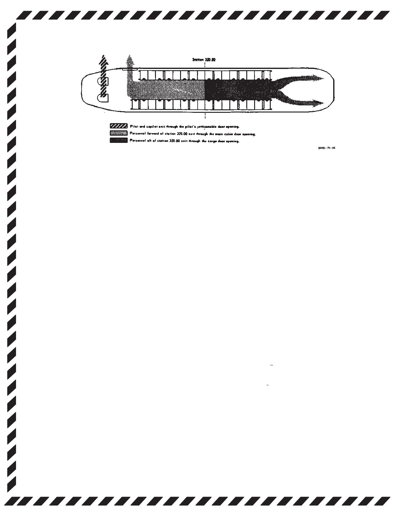
TM 1-1520-240-10
Figure 9-1-9. Ditching Exits
9-1-73. Flight Controls.
If both actuators are retracted, the landing will be normal.
If one or both actuators fail in extended position, the pitch
9-1-74. Longitudinal Cyclic Trim (LCT) System
atitude of the helicopter will be higher than normal during
Failure.
the approach and will be dependent upon the amount of
actuator extension at the time of the failure. Execute a
Should the system fail during cruise, with the cyclic trim
shallow approach to a hover or to the ground with a
system programmed for maximum forward tilt of the ro-
normal touchdown, avoiding large cyclic changes. When
tors, an abnormal nose-up attitude will result with de-
the aft gear areon the ground, apply brakes and lower the
creasing airspeed. Should one or both cyclic actuators
nose. As the forward gear touch the ground, the aircraft
fail in full retract position, airspeed must be limited ac-
will tend to accelerate more than normal.Continue to ap-
cording to Vne for retracted longitudinal cyclic trim. With
ply brakes as necessary to prevent forward movement.
both LCTs partially or fully retracted, maintain below Vne
If the helicopter is taxied with the actuators failed in the
and if failure occurs extended, maintain airspeed at or
extend position, use minimum control applications and
above 60 KIAS or until the approach to landing. Should
adjust the thrust control at ground detent or higher. There
the longitudinal cyclic trim system fail, perform the follow-
is an increased susceptibility to droop-stop pounding
ing:
with this condition.
CYCLIC TRIM circuit breakers - In. If cyclic trim opera-
9-1-75. Single AFCS Failure - Both Selected.
tion is not restored, proceed with the procedures below
for AUTO or MANUAL modes of operation.
A malfunction of the AFCS can usually be detected by an
abrubt attitude change (hardover) or unusual oscilations
If in AUTO mode:
in one or more of the flight control axes or by lighting of
1. Airspeed - Adjust.
the NO.1 or NO. 2 AFCS OFF caution. If flight is con-
ducted at low altitude such as contour or NOE, a climb to
2. CYCLIC TRIM switch - MANUAl.
higher altitude must be iniated before the pilot attempts
isolation of the defective system.
3. FWD and AFT CYCLIC TRIM switches -
Adjust for airspeed.
1. Airspeed - Reduce to 100 KIAS or Vne,
If LCT operation is not indicated:
whichever is slower.
FWD and AFT CYCLIC TRIM switches - RET for 30
2. Altitude - Adjust as required.
seconds, before landing.
NOTE
If in MANUAL mode:
A hardover in the opposite direction may oc-
cur when the malfunctioning AFCS is turned
1. Airspeed - Adjust.
off and the functioning AFCS reacts on the
2. CYCLIC TRIM switch - AUTO.
flight controls.
If normal LCT operation is not indicated:
3. AFCS SYSTEM SEL switch
- Isolate
defective system. Turn NO. 1 ON, if not
1. CYCLIC TRIM switch - MANUAl.
isolated, turn NO. 2 ON.
2. FWD and AFT CYCLIC TRIM switches -
If system is not isolated:
RET both LCTS for 30 seconds, before land-
ing.
AFCS SYSTEM SEL switch - OFF.
9-1-28
TM 1-1520-240-10
9-1-76. Dual AFCS Failure.
NOTE
Failure of a vertical gyro results in loss of its
AFCS SYSTEM SEL switch - OFF.
associated AFCS and should be treated as a
single AFCS failure.
If IMC;
1. Airspeed - 100 KIAS or Vne , whichever
Land as soon as practicable.
is slower.
2. Affected VGI switch - EMER.
9-1-77. Vertical Gyro (VGI) Malfunction.
3. AFCS - Select remaining system.
A vertical gyro malfunction will be indicated by an attitude
indicator failure, an AFCS OFF caution, and attitude
9-1-78. Differential Airspeed Hold Failure (DASH).
transients. If a vertical gyro failure occurs, proceed as
Differential airspeed hold failure will be recognized by
follows:
pitch attitude deviations. If DASH failure occurs, avoid
nose high attitudes.
CAUTION
9-1-79. Cockpit-Control Driver Actuator (CCDA)
Failure.
Failure of the No. 1 vertical gyro with altitude
1. THRUST CONT lever - Slip as required.
hold engaged may result in an altitude
runaway. If this occurs, disengage ALT
2. RADALT/BARO
ALT
switch-DISEN-
HOLD.
GAGED.
9-1-29/(9-1-30 blank)
TM 1-1520-240-10
SECTION II. MISSION EQUIPMENT
9-2-1. ARMAMENT
9-2-5. Hoist.
9-2-2. Armament Subsystems - M24 and M41.
WARNING
WARNING
Personnel must remain aft of the rescue
hatch and face away from the cable cutter.
Do not retract the bolt assembly immediately
The hoist cable may whip forward when it
when a hangover or cook-off is suspected. A
is cut and particles may be ejected from
hangover will normally occur within 5 sec-
the cable cutter.
onds from the time the primer is struck. A
cook-off will normally occur after 10 seconds
1. Personnel - Clear.
of contact with the chamber of a hot barrel.
If 150 cartridges are fired in a 2-minute
2. CABLE CUTTER switch - ON.
period, the barrel will be hot enough to
produce a cook-off.
9-2-6. ERFS II and FARE.
Misfire:
9-2-7. Failure of Fuel Quantity Gauge.
F 1. Weapon - Point at safe area.
F Remove filler cap from filler opening and look into tank.
F 2. Bolt - Retract, ensure cartridge ejects.
Using a explosion proof flashlight or other sealed beam
light source, locate fuel tabs which are attached to inside
F 3. If cartridge does not eject - Perform reme-
of column module at calibrated heights, increments of
dial action IAW TM 9--1005-224-10.
1/4. 1/2, and 3/4. Any tab covered with fuel will normally
NOTE
not be visible.
Keep cartridge separate from other ammuni-
9-2-8. No or Slow Fuel Transfer to the Main Tanks.
tion until it has been determined whether the
cartridge or the firing mechanism was at fault,
F 1. Manually operated fuel/defuel valve
-
it will be retained separate from other car-
Check CLOSED.
tridges until disposed of. If examination re-
veals that the firing mechanism was at fault,
F 2. Unisex couplings - Check.
the cartridge may be reloaded and fired.
F 3. Breakaway valves - Check open and for
Runaway Gun:
fracture.
F Break the ammunition feed belt.
F 4. Pumps - Check for operation.
9-2-3. Cargo.
F 5. Tank circuit breakers on FUEL CONTROL
9-2-4. Jettisoning External Cargo.
PANEL - Check reset in.
F 6. Ensure vent lines connected.
WARNING
9-2-9. IN FLIGHT Emergency ERFS II Fuel Transfer to
If a DUAL HOOK FAULT caution exists,
main Tanks.
normal and emergency release capability
for the forward and aft hook may be lost.
Using the FARE pump:
Use the manual emergency release sys-
tem only.
F 1. FARE pump module to rear most ERFS II
tank - Install.
Primary Method:
F 2. STA 380 fuel transfer hose to rear most
CARGO HOOK EMERG switch - REL ALL.
ERFS tank, fuel manifold hose - Discon-
Alternate Method:
nect.
F Forward, center and aft hook release lever - Pull aft.
F 3. Rear most ERFS II tank fuel manifold cou-
pling to FARE pump inlet (Top) coupling -
NOTE
Connect.
If the forward and/or aft hooks did not open
because of sling slack, apply a slight amount
F 4. FARE pump module outlet (lower) coupling
of thrust to load the hook(s) and force open.
to STA 380 fuel transfer hose - Connect.
9-2-1
TM 1-1520-240-10
NOTE
F 9. Once ERFSII tank empties, tank fuel man-
ifold “T” coupling - CLOSE.
Before FARE fuel transfer begins, a path from
the desired ERFS II tank to the helicopter
F 10. Next ERFS II tank fuel manifold “T”
main tanks must be established and the fuel
coupling - OPEN.
should be transferred from only one tank at a
F 11. Next/remaining ERFS II tank manually oper-
time.
ated fuel/defuel valve - OPEN.
F 5. “T” couplings on ERFS II tanks not being
transferred - CLOSE.
F 12. Once ERFS II tank empties, tank fuel man-
ifold “T” coupling - CLOSE.
F 13. FARE pump - OFF.
CAUTION
9-2-10. FARE Pump Failure During Ground FARE
There is no gauge on board the aircraft to
Refueling Operation.
provide measurements of GPM or PSIG.
The rate at which fuel is transferred from
F 1. Filters - Remove.
the ERFS II tanks to the Helicopter main
F 2. Overwing nozzle - Install and use.
tanks is 20 GPM. The rate at which fuel is
transferred from the ERFS II tanks using
F 3. Manually operated fuel/defuel valves -
the FARE pump and standard FARE trans-
OPEN.
fer hose assembly is 84 to 88 GPM. The
NOTE
FARE pump is rated at 120 GPM. Suction
If three ERFS II tanks are installed and all the
defueling pressure should not exceed -11
in-tanks are on, a 60 gallon per minute rate
PSIG. Do not exceed 5 PSI except in
can be achieved.
extreme emergency. The ERFS II outer
container is expected to fail at 10 PSI or
F 4. ERFS II tank pumps - ON.
greater. The crash resistant bladder will
prevent spillage and fuel can still be trans-
9-2-11. EAPS 1 FAIL and/or EAPS 2 FAIL Caution
ferred.
Light ON.
F 6. FARE valve control handle OFF LOAD
1. EAPS DOORS switch (affected engine) -
Position.
OPEN.
F 7. FARE pump - ON.
2. EAPS FAIL: caution capsule - Check out.
F 8. ERFS II tank manually operated fuel/defuel
F 3. EAPS BYPASS DOORS OPEN light -
valve - OPEN.
Verify light is ON.
9-2-2
TM 1-1520-240-10
APPENDIX A
REFERENCES
This appendix contains a list of official publications referenced in this manual and available to and required by CH-47D
helicopter operating activities. The publications listed are directly related to flight operation and maintenance of CH-47D
helicopters.
AR 70-50 .
Designating and Naming Military Aircraft, Rockets, and Guided
Missiles
AR 95-1 .
Army Aviation - General Provisions and Flight Regulations
AR 95-3 .
Aviation - General Provisions, Training, Standardization,
and Resource Management
AR 385-40 .
Accident Reporting and Records
DA PAM 738-751 .
The Army Maintenance Management System - Aviation
(TAMMS-A)
FM 1-202 .
Environmental Flight
FM 1-203 .
Fundamentals of Flight
FM 1-230 .
Meteorology for Army Aviation
FM 1-240 .
Instrument Flying and Navigation for Army Aviators
FM 1-513 .
Tactics, Techniques, And Procedures For Aerial Recovery of
Aircraft
TM 55-450-3/-4/-5 .
Multiservice Helicopter External Air Transport
TM 10-450-2 .
Helicopter Internal loads
TB 55 1500 -334-25 .
Conversion of Aircraft to Fire Resistant Hydraulic Fluid
TM 1-1500-250-23 .
Technical Manual Aviation Unit and Aviation Intermediate
Maintenance For general Tie-down and Mooring on All
Series Army Models AH-64, UH-60, CH-47, UH-1, AH-1,
OH-58 Helicopters.
TM 9-1005-224-10 .
Machine Gun, 7.62 MM, M60
TM 11-5810-262-OP .
Operating Procedures for Cryptographic Speech Equipment
TSEC/KY-58
TM 11-5841-294-12 .
Operator and Aviation Unit Maintenance Manual for Radar
Signal Detecting Set AN/APR-39A(V)1
TM 11-5855-300-10 .
Operating procedures for Heads Up Display AN/AVS-7
TM 11-5895-1199-12 .
Operator’s and Organizational Maintenance for Mark XII IFF
System (AN/APX-100, AN/APX-72)
TM 38-250 .
Preparation of Hazardous Materials for Military Aircraft
TM 55-1500-204-23 .
General Aircraft Maintenance Manual
TM 55-1500-342-23 .
Army Aviation Maintenance Engineering Manual: Weight and
Balance
TM 55-1520-240-23 .
Aviation Unit and Aviation Intermediate Maintenance Manual
TM 55-1520-240-CL .
Operators and Crewmembers Checklist
TM 55-1680-358-12&P .
Operator and Aviation Unit Maintenance Instructions for
Helicopters Internal Cargo Handling System
TM 750-244-1-5 .
Procedures for the Destruction of Aircraft and Associated
Equipment to Prevent Enemy Use
UFC 3-260-01 .
Airfield and Heliport Planning and Design
A-1/(A-2 blank)
TM 1-1520-240-10
APPENDIX B
GLOSSARY
ABBREVIATION
TERM
ABBREVIATION
TERM
AC .
Alternating Current
BRG .
Bearing
ACK .
Acknowledge
BTU .
British Thermal Unit
ACTR .
Actuator
C .
Celsius
ADF .
Automatic Direction Finding
CAS .
Calibrated Airspeed
AFCS .
Advanced Flight Control System
CCR .
Closed Circuit Refuel
AGL .
Above Ground Level
CCU .
Converter Control Unit
AIMS .
Air Traffic Control Radar Beacon
CDR’s .
Commander’s
System Identification Friendly or
CDU .
Computer Display Unit or Control
foe Mark XII Identification System
Display Unit
AJ .
Anti-Jam
C.G. .
Center-of-Gravity
AK .
Automatic Keying
CGI .
Cruise Guide Indicator
ALP .
Alpha
CHAN .
Channel
ALSE .
Aviation Life Support Equipment
CHK .
Check
ALT .
Altitude
CKPT .
Cockpit
AM .
Amplitude Modulated
CL .
Checklist
AME .
Amplitude Modulation Equivalent
AMP .
Ampere
CL .
Center Line
ANT .
Antenna
CLR .
Clear
CLR-VC .
Clear Voice
ACK .
Acknowledge
ANVIS .
Aviation Night/Vision Imaging Sys
CM .
Countermeasures
tem
CMD .
Command
APU .
Auxiliary Power Unit
CNV .
Crypto Net Variable
APPROX .
Approximately
COMM .
Communication
AR .
Army Regulations
COMP .
Compass
AS .
Airspeed
COMPT .
Compartment
ASTM .
American Society for Testing Mate
COND .
Condition
rials
CONT or
ATM .
Aircrew Training Manual
CONTR .
Control
AUTO .
Automatic
COPLT or
AUX .
Auxiliary
CPLT .
Copilot
AVAIL .
Available
CPDU .
Copilot Display Unit
AVGAS .
Aviation Gasoline
CPM .
Control Processor and
BARO .
Barometric
Communications
BATT or
CRS .
Course
BTRY .
Battery
CRT .
Cathode Ray Tube
BCN .
Beacon
CTR .
Center
BFO .
Beat-Frequency Oscillator
CW .
Continuous Wave
BIT .
Built in Test
DA .
Density Altitude
BITE .
Built in Test Equipment
DASH .
Differential Airspeed Hold
BL .
Butt Line
DAT .
Data
BRK .
Brake
DC .
Direct Current
BRT .
Bright
DCLT .
Declutter
B-1
TM 1-1520-240-10
ABBREVIATION
TERM
ABBREVIATION
TERM
DCP .
Differential Collective Pitch
FM-M .
Frequency Hopping Master
DEC .
Decrease
FMT .
Frequency Managed Training
DEST .
Destination
FOD .
Foreign Object Damage
DET or
FPM or
DETR .
Detector
FT/MIN .
Feet per Minute
DF .
Direction Finder
FREQ or
DIM .
Dimensions
FRQ .
Frequency
DIS .
Disable
FT .
Feet
DISCH .
Discharge
FUSLG or
DISP .
Display or Dispenser
FUS .
Fuselage
DIST .
Distance
FWD .
Forward
DN .
Down
G .
Green
DOP .
Doppler
G’s .
Gravity
DSPL .
Display
GALS .
Gallons
DU .
Display Unit
GCA .
Ground Controlled Approach
E .
East
GC XMIT .
Guard Transmitter
EAPS .
Engine Air Particle Separator
GEN .
Generator
ECM .
Electronic Countermeasure
GMT .
Greenwich Mean Time
ECCM .
Electronic Counter Countermea
GND .
Ground
sures
GPM .
Gallons per Minute
EDT .
Edit
GS .
Glide Slope
EMER or
GS/TK .
Ground Speed/Track
EMERG .
Emergency
GW .
Gross Weight
ENG .
Engine
GYRO(s) .
Gyroscope(s)
ENT .
Enter
H .
High
ERFS .
Extended Range Fuel System
HDG .
Heading
ERFS II .
Extended Range Fuel System II
HF .
High Frequency
ETL .
Effective Translational Lift
Hg .
Mercury
EXH .
Exhaust
HGT .
Height
EXT .
Extend, Extinguisher, or External
HI .
High
F .
Fahrenheit
HICHS .
Helicopter Internal Cargo Handling
FADEC .
Full Authority Digital Electronic
System
Control
HIGE .
Hover In Ground Effect
FARE .
Forward Area Refueling
HIT .
Health Indicator Test
Equipment
FAT .
Free Air Temperature
HOGE .
Hover Out of Ground Effect
FCP .
Fuel Control Panel
HR .
Hour
FH .
Frequency Hopping
HSI .
Horizontal Situation Indicator
FIG .
Figure
HTG .
Heating
FIL .
Filament
HTR .
Heater
FL .
Flow
HUD .
Heads Up Display
FLP .
Flight Plan
HYD .
Hydraulic
FLT .
Flight
Hz .
Hertz
FLT CONT .
Flight Control
I .
Inner
FM .
Frequency Modulated
IAS .
Indicated Airspeed
FMCP .
Fuel Management Control Panel
ICS .
Intercommunication System
B-2
TM 1-1520-240-10
ABBREVIATION
TERM
ABBREVIATION
TERM
ID or
MA .
Missile Alert
IDENT .
Identification
MAG .
Magnetic
IFF .
Identify Friend or Foe
MAL .
Malfunction
IFR .
Instrument Flight Regulations
MAM .
Manual
IGE .
In Ground Effect
MAX .
Maximum
IGN .
Ignition
MB or
ILCA .
Integrated Lower Control Actuator
MKR BCN .
Marker Beacon
ILS .
Instrument Landing System
M-C .
Mode C
IMC .
Instrument Meteorological Condi
MCW .
Modulated Carrier Wave
tions
MDL .
Module
IN. or “ .
Increase
MED .
Medium
INC .
Increase
MEM .
Memory
IND .
Indicator
MEM
INOP .
Inoperative
LOAD .
Memory Load
INST .
Instruments
MHz .
Megahertz
INT or
MID .
Middle
INPH .
Interphone
MIL .
Angular Measurement, Military
INTR .
Interior
MIN .
Minute(s) or Minimum
ITO .
Instrument Takeoff
MK .
Manual keying
JP-4, JP-5
MM .
Millimeter
or JP-8 .
Jet Petroleum
MOM .
Momentary or Moment
K .
Key
MOM. ON .
Momentary On
KYBD .
Keyboard
MSG .
Message
kHz .
Kilohertz
KIAS .
Knots Indicated Airspeed
MSL .
Mean Sea Level or Missile
MST .
Master Caution
Km .
Kilometer
KN or KTS .
Knots
MTR .
Motor
L .
Left
MWOD .
Multiple Word of Day
LAT/LONG .
Latitude/Longitude
N .
North
LB .
Pounds(s)
NAC .
Nacelle
LB-FT .
Pound-Feet (Torque)
NAV .
Navigation
LB/GAL .
Pounds per Gallon
NB .
Narrow Band
LB/HR .
Pounds per Hour
NM .
Nautical Mile
LBL .
Left Butt Line
NO .
Number
LCT .
Longitudinal Cyclic Trim
NORM .
Normal
LD .
Load
NPU .
Navigation Processor Unit
DL-V .
Load Variable
NVG .
Night Vision Goggles
LF .
Low Frequency
N1 .
Gas Producer (Speed)
LG .
Length
N2 .
Power Turbine (Speed)
LH .
Left-Hand
O .
Outer
LO .
Low
OBS .
Obstacle
LOC .
Location
OFST .
Offset
LSB .
Lower Sideband
OGE .
Out-of-Ground Effect
LTG .
Lighting
ONS .
Omega Navigation System
LTS .
Lights
OP .
Operation
LVL .
Level
OU .
Optical Unit
M .
Mode or Middle
OUTB’D .
Outboard
B-3
TM 1-1520-240-10
ABBREVIATION
TERM
ABBREVIATION
TERM
OVHD or
RET or
OVRHD .
Overhead
RETR .
Retract
OVSP .
Overspeed
Retrans or
PA .
Pressure Altitude
RE-X .
Retransmission
PAM .
Pamphlet
REV CUR .
Reverse Current
PARA .
Paragraph
RF .
Radio Frequency
PDP .
Power Distribution Panel
RH .
Right-Hand
PDU .
Pilot Display Unit
RRPM .
Rotor Revolutions per Minute
PGRM .
Program
RPM .
Revolutions per Minuter
PH .
Phase
RV .
Receive Variable
PLT .
Pilot
RX .
Receive or Receiver
P/N .
Part Number
S .
South
PNL .
Panel
SDA .
Synchro Discrete and Analog
POS .
Position
SDC .
Signal Data Converter
PP .
Present Position
SDR .
Symbol Generator and Driver
PPH .
Pounds per Hour
SEC .
Secondary
PRESS .
Pressure
SECT .
Section
PRI .
Primary
SEL .
Select
PROG .
Program
SELDAR .
Selective Address
PS .
Power Supply
SENS .
Sensitivity
PSCU .
Power Supply Calibration Unit
SHP .
Shaft Horsepower
PSF .
Pounds per Square Foot
SL .
Seal Level
PSI .
Pounds per Square Inch
S/N .
Serial Number
PSIG .
Pounds per Square Inch Gage
SLT .
Searchlight
PT .
Pint
SP/DIR .
Speed/Direction
PTIT .
Power Turbine Inlet Temperature
SPEC .
Specification
PTT .
Push-to-Talk or Press-to-Talk
SPH .
Spheroid
PTU .
Power Transfer Unit
SQ .
Squelch or Square
PVT .
Private
SQ DIS/
PWR .
Power
TONE .
Squelch Disable/Tone
QT .
Quart
SQ FT .
Square Feet
QTY .
Quantity
STA .
Station
R .
Red
STBY .
Standby
R or RT .
Right
STO or
RAD .
Radar
STR .
Store
RAM .
Random Access Memory
SYS .
System
RBL .
Right Butt Line
T/R + G .
Transmit/Receive Plus Guard
RC .
Rate of Climb
Channel
RCU .
Remoter Control Unit
TACH .
Tachometer
RCVR .
Receiver
TAS .
True Airspeed
RD .
Rate of Descent
TCK .
Track
RECP or
TGT .
Target
REC .
Receptacle
TEMP .
Temperature
RECT .
Rectifier
TOD .
Time of Day
REF .
Reference
TQ/ENG .
Torque per Engine
REL .
Release
TX .
Transmit or Transmitter
REQD .
Required
TYP .
Typical
B-4
TM 1-1520-240-10
ABBREVIATION
TERM
ABBREVIATION
TERM
UHF .
Ultra High Frequency
VSI .
Vertical Speed Indicator
US .
United States
W .
West or Wide
USB .
Upper Sideband
WARN .
Warning
UTIL .
Utility
WB .
Wide Band
UTM .
Universal Transverse Mercator
WL .
Water Line
V .
Volt(s)
WOD .
Word of Day
VAC .
Volts Alternating Current
WSHLD or
VAR .
Variation
W/S .
Windshield
Vcgi .
Estimated Airspeed Limit with an
WT .
Weight
Operating Cruise Guide Indicator
X .
Times or By
VDC .
Volts Direct Current
XFEED .
Crossfeed
VENT .
Ventilate
XFER .
Transfer
VFR .
Visual Flight Regulations
XMIT .
Transmit
Vh .
Maximum Airspeed in Level Flight
XMSN .
Transmission
(as Limited by CGI, PTIT, or
XTK/TKE .
Cross Track/Track Angle Error
Torque)
_ .
Degrees or Temperature
VHF .
Very High Frequency
_C .
Degrees Celsius
VGI .
Vertical Gyro Indicator
_/KTS .
Degrees per Knots
VLF .
Very Low Frequency
% .
Percent
Vmax .
Maximum Airspeed Limit
3/REV .
Three Vibrations for Each Revolu
(Indicator Red Line)
tion of the Rotor
Vne .
Velocity (Airspeed) Never Exceed
VOL .
Volume
VOR .
Very High Frequency Omni-Direc
tional Range
B-5
TM 1-1520-240-10
APPENDIX C
CONDITIONAL INSPECTIONS
This appendix contains those conditions which require a write-up in DA Form 2408-13-1. An entry shall state the limit
(s) exceeded, range, timeabove limits, and any additional data that would maintenance personnel in maintenance
action that may be required.
CONDITION
2408-13-1 ENTRY REQUIRED
REMARKS
Water landings have been per-
Comment
formed.
Salt water landings.
Comment
Landing in mud or swampy terrain or
Comment
difficulty in starting or torching of the
cabin heater.
Landing gear wheels have been
Comment
submerged in water or mud.
Helicopter has been washed or
Comment
subjected to heavy rain.
Helicopter is operated within 200
Comment
miles of volcanic activity.
Helicopter is operated within 10
Comment
miles of salt water or 1000 feet of it’s
surface.
Whenever the aircraft is flown with a
Codes(s) and when recognized.
Refer to the DECU Fault Code List/
DECU fault code other than “88”.
Matrix in Chapter 2.
Whenever the -714A engine is shut-
Comment
down via the Fire Pull Handle or an
engine failure occurs.
Fuel vents overboard or uneven
Comment
tank depletion rate occurs from an
auxiliaryfuel tank during normal op-
eration.
Fuel vents overboard from a main
Comment
fuel tank during normal during nor-
mal flight operations.
Whenever emergency fuel is used.
Type of fuel, additives, and duration
Operation with emergency fuel
of operation.
should not exceed 6 hours cumula-
tive time.
When aircraft is fueled with JP8 fuel
Amount of fuel and tanks affected.
Operate aircraft without restrictions,
containing +100 additive.
considered +100 additive free after
refueling with 3 full useable fuel
loads of JP8. Contact: USAPC, Mr.
Del Leese, DSN 977-8580.
Helicopter has been subjected to a
Comment
hard landing or when emergency
lightsare actuated during landing.
When two different types of oil are
Comment
Respective engine oil shall be
mixed in either engine.
changed and the system flushed
within 6 hours
of engine
operation.
C-1
TM 1-1520-240-10
CONDITION
2408-13-1 ENTRY REQUIRED
REMARKS
Engine oil consumption exceeds 2
Comment
quarts per hour.
Engine is subjected to sudden stop-
Comment
page or a sudden reduction in RPM.
Engine compressor stall (surge) is
Comment
experienced.
712 Each time emergency power in-
Comment
dicator is tripped.
Emergency power reaches 30 min-
Comment
ute cumulative time.
When starting or beeping engines, if
Comment
Do not restart affected engine.
loud noises or shocks are followed
by sudden high increases in engine
torque, or if a torquemeter is station-
ary at high value after shutdown.
When starting engines, if either en-
Comment
gine fails to accelerate to flight
speed
When CO2 is applied to engine inlet
Comment
or exhaust.
When torquemeter is stationary at a
Comment
high value after shutdown.
When the transmission filter bypass
Comment
button is extended.
When a transmission is suspected
Comment
of excessive oil leakage.
When a transmission oil system has
Comment
been contaminated with hydraulic
fluid.
When two different types of oil are
Comment
Respective transmission oil shall be
mixed in the forward, combining, aft,
changed and the system flushed
or engine transmissions.
within 6 hours of transmission op-
eration.
When MIL-H-83282 hydraulic fluid is
Indicate quantity added.
not available and MIL-H-5606 is
used.
When rotary wing blade has made
Comment
contact with a foreign object or when
the power train has been subjected
to a sudden reduction in RRPM.
Helicopter is struck by lightning.
Comment
When a rotary wing blade has been
Comment
struck by lightning.
When a rotary wing has been flap-
Comment
ping due to high winds.
C-2
TM 1-1520-240-10
CONDITION
2408-13-1 ENTRY REQUIRED
REMARKS
When the rotor blades are pounded
Comment
against the droop stops, or have ex-
perienced violent and heavy flap-
ping, or have been exposed to hurri-
cane or tornadic winds.
When a rotorhead is suspected of
Comment
excessive oil leakage.
When internal failure (metal
Comment
contamination) of a flight control or
utility hydraulic pump or motor
occurs.
When two different types of oil are
Comment
APU oil shall be changed and the
mixed in the APU.
system flushed within 6 hours of
APU operation.
When the compass is suspected of
Comment
being in error.
After every manual release of the
Comment
center cargo hook under the load.
When a fault indication is displayed
Comment
on the MAINTENANCE PANEL.
When any Chapter 5 limitations
Limit or limits exceeded, range, time
have been exceeded.
above limits, and any additional data
that would aid maintenance person-
nel.
Whenever the aircraft is refueled
2408-13-1 Amount of JP8+100 fuel This is an informational entry and may
with JP8+100.
recieved in gallons or pounds.
be removed after three refuelings of
JP8 without the +100 additive.
C-3/(C-4 blank)
TM 1-1520-240-10
ALPHABETICAL INDEX
Subject
Paragraph, Figure,
Subject
Paragraph, Figure,
Table Number
Table Number
Description .
7-11-1, 7A-11-1
A
Use of Chart .
7-11-2, 7A-11-2
Abbreviations .
B-1
Airspeed Hold .
2-5-10
AC Cabin Utility Receptacles .
2-9-14
Airspeed Indicator .
2-14-5
Accumulator Gage .
6-6-26
AIRSPEED LIMITS
Accumulator Precharge Limits .
F 2-15-3
Airspeed Operating Limits .
5-5-1
AC System .
2-11-2
AFCS Limitations .
5-5-7
AC Power Supply
Airspeed Limitations - Longitudinal Cyclic
(Typical)
712
F FO-3
Trim Retracted .
F 5-5-2
AC Power Supply (Typical) 714A .
F FO-6
Airspeed Limitations With An Inoperative Cruise
Electrical Power Panel .
F 2-11-2
Guide Indicator .
5-5-2, F 5-5-1
EXT PWR Caution .
2-11-5
Airspeed Limitations With An Operative or
External Power Receptacles .
F 2-11-1
Inoperative Cruise Guide Indicator .
5-5-3
Generator Control Switches .
2-11-3
External Cargo Airspeed Limits .
5-5-4
GEN OFF Cautions .
2-11-4
Longitudinal Cyclic Trim (LCT) Actuator
Airspeed Limits .
5-5-5
Power Distribution Panels (Typical)712 .
F FO-2
Air-to-Ground Towing .
5-9-1
Power Distribution Panels (Typical)714A . . F FO-5
Altimeter .
2-14-6
ADDITIONAL LIMITATIONS
Altitude Hold .
2-5-11
Air-to-Ground Towing .
5-9-1
Antenna Locations .
F 3-3
APU Operation .
5-9-2
Antenna System .
3-2-3
Extended Range Fuel System II(ERFSII) 4-80, 5-9-6
Anticollision Lights .
2-13-5
Pitot Tube and AFCS Sideslip Port .
5-9-3
ANTI COL Light Switches .
2-13-6
Single Point Refueling .
5-9-5
Anti-Icing Systems .
2-9-1
Windshield Heat .
5-9-4
ANTI ICE Panel .
2-9-2
Advanced Flight Control System (AFCS) .
2-5-7
Anti Ice Panel .
F 2-9-1
Advanced Flight Control System Panel .
F 2-5-3
Appendix A, References .
A-1
AFCS Control Panel .
2-5-15
Appendix B, Abbreviation .
B-1
AFCS OFF Caution .
2-5-17
Appendix C, Conditional Inspections .
C-1
Airspeed Hold .
2-5-10
APU ON Caution .
2-12-4
Altitude Hold .
2-5-11
APU Switch .
2-12-3
Bank Angle Hold .
2-5-8
Armament Subsystem .
4-2-1, F 4-2-1
Command Select Switch .
2-5-18
Machine Gun .
4-2-2
Controls and Indicators .
2-5-14
Ammunition Can and Ejection Control
Cyclic Trim Indicators .
2-5-16
Bag .
F 4-2-4
Forward and Aft Cyclic Trim Indicators .
F 2-5-4
Ammunition Can - Installed .
F 4-2-8
Heading Hold .
2-5-9
Ejection Control Bag - Installed .
4-2-7
Heading Select .
2-5-12
Machine Gun Controls .
4-2-4
Longitudinal Cyclic Trim System .
2-5-13
Machine Gun M60D .
F 4-2-2
Aerobatics Prohibition .
5-1-29
Aerodynamic Loads .
8-3-6
Machine Gun Positioned on Pintle - Left
AFS Limitations .
5-5-7
Side Shown .
F 4-2-9
AFCS Trim Switch .
2-5-5
Machine Gun Stowed on Right Mount .
F 4-2-6
After Landing .
8-2-35
Right Machine Gun Mount - Installed .
F 4-2-5
After Landing (Abbreviated) .
8-2-36
Ammunition .
4-2-10
AGENT DISCH Switch .
2-2-4
Armament Subsystem M24 Data .
T 4-2-1
AIMS Altimeter .
2-14-2
Operation - Armament Subsystem M24 .
4-2-6
Air Control Handles .
2-10-4
Preflight Checks .
4-2-7
AIRCRAFT AND SYSTEMS DESCRIPTION
Before Takeoff Check .
4-2-8
AND OPERATION
Infight Operation .
4-2-9
General .
2-1-1
M24 Mount .
F 4-2-3
General Arrangement .
F FO-1
Mount Assemblies (M24) .
4-2-3
Gross Weight .
2-1-2
Mount Assembly Stops, Cams, Quick-
Pin,
Principal Dimensions Diagram .
F 2-1-1
Release and Shock Cord (M24) .
4-2-5
Turning Radii .
F 2-1-2
Armament Subsystems - M24 and M41 .
9-2-2
Aircraft Compartment and Loading Diagram . . . F 6-1-1
Armament Subsystem M41 .
4-2-11
Aircraft Designation System .
1-1-13
Armament Subsystem M41 Data .
T 4-2-3
Airspeed Calibration Chart .
F 7-11-1, F 7A-11-1
Operation - Armament
Conditions .
7-11-3, 7A-11-3
Subsystem M41 .
4-2-14
Index-1
TM 1-1520-240-10
Subject
Paragraph, Figure,
Subject
Paragraph, Figure,
Table Number
Table Number
Mount Assembly (M41) .
4-2-12
Normal Operation .
6-6-29
Mount Assembly Stops, Cams, Quick-Release
Ramp Controls .
F 6-6-8
Pin, and Elastic Cord (M41) .
4-2-13
Ramp Sequence Valve .
6-6-24
M41 Mount - Installed on Ramp .
F 4-2-10
Ramp Control Valve .
6-6-23
Armored Seats .
2-1-20
Cargo Hook Cautions .
4-3-13
Army Aviation Safety Program .
1-1-9
Cargo Hook Controls .
4-31-11
Ash Trays .
2-9-16
Cargo Hook Limitations .
5-4-3
Attitude indicator .
2-14-16
Cargo Hooks Operational Check .
4-3-16
Authorized Cartridges .
T 4-2-2
CARGO LOADING
Autorotational Approach Corridor for Second
Cargo Compartment .
6-6-2
Engine Failure from Single Engine
Cargo Compartment Dimensions . . F 6-6-1
Level Flight .
F 9-9
Cargo Compartment Floor .
6-6-6
Auxiliary Power Unit .
F 2-12-2
Concentrated Load Limits .
6-6-11
Emergency APU Fluid
Concentrated Loads .
6-6-10
Shut Off Valve .
2-12-5, F 2-12-1
Load Limits .
6-6-12
APU ON Caution .
F 2-14-5, F 2-14-6
Strength Areas .
6-6-7
APU Switch .
2-12-3
Uniformly Distributed Load Limits .
6-6-9
Electronic Sequencing Unit .
2-12-2
Uniformly Distributed Loads .
6-6-8
General .
2-12-1
Compartment Capacities .
6-6-14
Aviation Life Support Equipment (ALSE) .
8-1-2
Compartment Data .
F 6-6-4
Avionics Equipment Configuration .
3-1-2
Compartment Identification .
6-6-13
Antenna Locations .
F 3-2-3
Compartment Loading .
6-67, F 6-6--12
Antenna System .
3-2-3
General .
6-6-1
Avionics Power Supply .
3-1-3
General Instructions for Loading, Securing,
Communications/Navigation Equipment . . T 3-1-1
and Unloading Cargo .
6-6--39
Description .
3-1-1
Restraint .
6-6--41
B
Weight and Balance .
6-6--40
Lower Rescue Door .
6-6-5
Bank Angle Hold .
2-5-8
Main Cabin Entrance .
6-6-3
Bank Angle Limitations .
F 5-6-1
Maximum Package Size .
F 6-6-2
Bank Limitations .
5-6-2
Stowage Locations .
F 6-19
BATT SYS MAL Caution .
2-11-9
Utility Hatch Door .
6-6-4, F 6-6--10
BATT Switch .
2-11-7
Cargo Loading Aids .
6-6-18
Before Landing .
8-2-31
Auxiliary Loading Ramps .
6-6-20
Before Leaving Helicopter .
8-2-38
Cargo Door Cranking .
F 6-6--11
BIT 714A .
2-3-34
Cargo Door and Ramp .
6-47, F 6-15
BRK STEER Isolation Switch .
2-6-7
Cargo Loading Ramp .
6-6-19
Brake System .
2-1-7
Winch .
6-6--21
Brake Pedals .
2-1-8
CAUTION LT Panel .
2-14-30
Brakes and Steering Isolation Switch .
2-1-10
Center Console (Typical) .
F 2-1-6
Parking Brake Handle .
2-1-9
Center Console With XM-130
Steering and Swivel Lock System .
2-1-5
Countermeasures (Typical) .
F 2-1-5
STEERING CONTROL PANEL .
2-1-6, F 2-1-4
Center Console With AN/ALE 47
Bulk Cargo Tiedown .
6-6-54
Countermeasures (Typical) .
F 2-1-6
C
Center Cargo Hook .
4-3-8
Center Cargo Hook and Cargo Hook
CABIN AND RAMP LIGHTS Switches .
2-13-25
Release .
F 4-3-13
Cabin and Ramp Lights .
2-13-24
Center Cargo Hook Loading Pole . .. F -3-9
Cabin Heat Controls .
2-10-5
Center Cargo Hook Loading Pole
Cabin Lighting and Controls .
F 2-13-4
(Typical) .
F 4-3-12
Canted Console (Typical) .
F 2-1-7
Center Hook Loads .
8-3-3
Canted and Center Console Lights .
2-13-16
Aerodynamic Loads .
8-3-6
Cargo .
9-2-3
High Density Loads .
8-3-5
Jettisoning External Cargo .
9-2-4
Low Density Loads .
8-3-4
Cargo Center of Gravity .
6-60
Multi-Hook Loads .
8-3-7
Cargo Dimensions .
6-6-34
Center Instrument Panel Lights .
2-13-14
Cargo Door and Ramp .
6-6-22, F 6-6-7
Center Instrument Panel
Pressure Actuated Valve .
6-6-25
712
Ramp Operation .
6-6-28
(Typical)
F 2-1-8
In-Flight Operation .
6-6-30
Center Instrument Panel
Manual Operation - Cargo Door .
6-6-32
714A .
F 2-1-12
Index-2
TM 1-1520-240-10
Subject
Paragraph, Figure,
Subject
Paragraph, Figure,
Table Number
Table Number
CENTERING DEVICE RELEASE
Countermeasures Dispenser System,
Switch .
2-5-4
AN/ALE 47 .
4-1-17, F 4-1-6
Center-of-Gravity Limitations .
5-19
ALE 47 Flare Dispenser System .
F 4-6
C.G. Limits Chart .
F 6-25
Controls and Function, Countermeasures
CGI TEST Switch .
2-212
Dispenser System
Change Symbol Explanation .
1-1-12
(AN/ALE-47) .
4-1-18, F 4-1-6
Checklist .
8-2-4
Dispenser Assemblies .
4-1-22
CHRONOMETER .
2-14-21
AN/ALE-47 Safety Switch .
4-1-21
Chronometer .
F 2-14-4
AN/ALE-47 Sequencers .
4-1-20
Normal Operation
Flight Operations .
4-1-25
- CHRONOMETER .
2-14-22
Normal Operation .
4-1-24
Setting ET .
2-14-24
Payload Module Assemblies .
4-1-23
Setting GMT .
2-14-23
The AN/ALE-47 Programmer .
4-1-19
Setting LT .
2-14-24
Crew Briefing .
8-1-4
Test Mode .
2-14-26
Crew Duties/Responsibilities .
8-1-3
Classification of Helicopter .
6-1-3
Cruise Charts
Climb - Descent Chart .
F 7-9-1, F 7A-9-1
Conditions .
7-38
Climb Performance .
F 7-9-2, F 7A-9-2
Description .
7-36
Conditions .
7-9-3, 7A-9-3
Example Cruise Chart .
F 7-9
Description .
7-9-1, 7A-9-1
Performance Penalties with EAPS .
7-39
Use of Charts .
7-9-2, 7A-9-2
EAPS Penalty Table .
T 7-1
Climb .
8-3-28
Use of Charts .
7-37
CMDS Messages .
4-1-26
Cruise Check .
8-2-29
Cockpit Air Knob .
2-10-3
CRUISE GUIDE Indicator .
2-14-3
Cockpit Lighting and Control .
F 2-13-2
Cruise Guide Indicator .
F 2-14-3
Cockpit Rearview Mirror .
2-9-11
Cruise Guide Indicator System .
2-14-2
Cockpit Utility Receptacles .
2-9-14
CTR INST Switch .
2-13-15
Cockpit and Controls .
F 2-1-3
CYCLIC Stick .
2-5-3
Cold Weather Operation .
8-4-1
Cyclic Stick Grip .
F 2-5 -2
After landing .
8-4-15
Cyclic Trim Indicators .
2-5-16
Before Leaving Aircraft .
8-4-17
Descent .
8-4-13
D
During Flight .
8-4-12
DC Cabin Utility Receptacles .
2-9-15
Engine Shutdown .
8-4-16
DC System .
2-11-6
Engine Starting .
8-4-8
BATT Switch .
2-11-7
Warmup and Ground Tests .
8-4-9
BATT SYS MAL Caution .
2-11-9
General .
8-4-2
Heater Normal Operation .
8-4-4
DC Power Supply (Typical) 712 .
F FO-4
Landing in Snow .
8-4-14
DC Power Supply (Typical) 714A .
F FO-7
Preparation for Flight .
8-4-3
RECT OFF Cautions .
2-11-8
Takeoff .
8-4-11
DD Form 365-3 Chart C - Basic Weight and
Taxiing .
8-4-10
Balance Record .
6-2-1
Combining and Engine Transmission
DD Form 365-4 (Weight and Balance
Lubrication Systems .
2-7-5
Clearance Form F) .
6-2-2
Command Select Switch .
2-5-18
DECU Panel 714A .
F 2-3-7
Compass Correction Card Holder .
2-9-17
DECU Unit 714A .
2-3-33
Continuous Torque Available . 7-4-1, F7-4-5,
T55-GA-714A DECU BIT Fault Code
7A-4-1, F 7A-4-5
List Matrix .
T 2-3-1
Conditions .
7-4-3, 7A-4-3
DESCENT .
8-2-30
Use of Chart .
7-4-4, 7A-4-4
DESERT AND HOT WEATHER
Copilot Instrument Panel
OPERATION .
8-4-17
(Typical)
712
F 2-1-7
Before Leaving the Aircraft .
8-4-26
Copilot Instrument Panel
Engine Shutdown .
8-4-25
(Typical) 714A .
F 2-1-11
Engine Starting .
8-4-21
Countermeasures Set (AN/ALQ-156) .
4-1-5
General .
8-4-19
Controls and Indicators, Missile Detector . . .
Landing .
8-4-24
Set (AN/ALQ-156) .
4-1-6
Preparation for Flight .
8-4-20
Countermeasures Set Control Panel
Takeoff, Climb, Cruise, and Descent .
8-4-23
(AN/ALQ-156) .
F 4-5-1
Taxiing .
8-4-22
Normal Operation;
Destruction of Army Material to Prevent
Countermeasure Set .
4-1-7
Enemy Use .
1-1-10
Index-3
TM 1-1520-240-10
Subject
Paragraph, Figure,
Subject
Paragraph, Figure,
Table Number
Table Number
Direction Finder Set (AN/ARN-89) .
3-3-5
General Operating Procedures
Controls and Function, Direction
for Entering Data .
3-3-49
Finder Set (AN/ARN-89) .
3-3-6
GPS Data Loader Receptacle 3-3-53, F 3-19
Direction Finder Control .
F 3-3-2
Controls and Functions - GPS Data
Normal Operation -
Loader Receptacle .
3-3-54
Direction Finder Set .
3-3-7
Normal Operation - GPS Data Loader Re-
Directional Gyro (CN-998/ASN-43) .
F 3-3-4
ceptacle .
3-3-55
Directional Pedals .
2-5-6
GPS KYK-13
Dome Lights .
2-13-18
Remote Fill Panel .
3-94, F 3-21
Dome Switch .
2-13-19
Controls and Function - GPS KYK-13
Doppler Navigation Set
Remote Fill Panel .
3-3-57
(AN/ASN-128) .
3-3-11, F 3-3-5
Normal Operation - GPS KYK-13
Computer-Display Unit Data Displays T 3-3-2
Remote Fill Panel .
3-3-58
Controls and Function - Doppler
GPS Landing Mode .
3-3-45
GPS Zeroize Switch .
3-3-59, 3-4-4
Navigation Set .
3-3-12, F 3-3-5, T 3-3-2
Normal Operation GPS Zeroize
Data Entry .
3-3-14
Switch .
3-3-60, 3-4-5
Dead Reckoning Navigation .
3-3-30
Remote GPS Data Loader Receptacle/
Display and Keyboard Operation .
3-3-13
KYK-13 Fill Panel .
F 3-3-9, F 3-4-2
Doppler Navigation Set Control
Graphic Definition of Course Terms F 3-3-8
(AN/ASN-128) .
F 3-3-11
Map Datum Codes .
T 3-3-4
Entering Data .
3-3-16
Modes of Operation .
3-3-38
Entering Ground Speed and Track .
3-3-20
Navigate Mode .
3-3-40
Entering Present Position or Destination
Combined Mode (Default or
in LAT/LONG .
3-3-19
Primary Mode of Operation .
3-3-41
Entering Present Position or Destination
Doppler Mode .
3-3-43
in UTM .
3-3-18
GPS Mode .
3-3-42
Entering Spheroid and/or Variation .
3-3-17
Off Mode .
3-3-39
Starting Procedure .
3-3-15
Preflight Procedures .
3-3-50
Flight Procedures .
3-3-22, 3-89
Route Sequencing Modes .
3-3-47
FLY-TO-DEST Operation .
3-3-25
Test Mode .
3-3-44
Left-Right Steering Signals .
3-3-26
To-To Route Modes .
3-3-48
Transferring Stored Target Coordinates from
Drag Chart .
F 7-8-1, F 7A-8-1
One Location to Another .
3-3-28
Change in Drag Area of Typical
Transferring Variation from One Location
External Loads .
T 7-8-1, T7A-8-1
to Another .
3-3-29
Conditions .
7-8-3, 7A-8-3
Update of Present Position from
Description .
7-8-1, 7A-8-1
Landmark .
3-3-24
Use of Charts .
7-8-2, 7A-8-2
Update of Present Position from
Dual Engine Failure .
9-1-10
Stored Destination .
3-3-23
Dual Hook Fault Caution .
4-3-15
Operation During and After Power
Interruption .
3-3-31
E
Spheroid Data Codes .
T 3-3-3
Starting Procedure .
3-3-15
Electrical Power Panel .
F 2-11-2
Stopping Procedure .
3-3-32
Electrical Power Supply System .
2-11-1
System Initialization .
3-3-21
AC System .
2-11-2
Target Store (TGT STR) Operation .
3-3-27
DC System .
2-11-6
Electronic Sequencing Unit .
2-12-2
Doppler/Navigation Set
Engine Air Particle Separator
AN/ASN-128B (DGNS) .
3-3-36
(EAPS) .
2-3-41
CDU Operation .
3-3-46
Differential Pressure Switch .
2-3-44
Controls and Function - Doppler
EAPS Switches .
2-3-45
Navigation Set .
3-3-12
EAPS Bypass Doors .
2-3-42
Controls and Indicator
EAPS 1 Shown With
-Horizontal Situation Indicators .
3-3-34
Bypass Doors Open .
F 2-3-9
Controls, Displays and Function .
3-3-37
EAPS Control Boxes .
2-3-43, F2-3-10
Doppler/GPS Navigation System
EAPS Module/Engine Screen
AN/ASN-128B .
F 3-3-7
Weight and Balance .
T 6-5-1
Flight Procedures .
3-3-22
EAPS Protective Covers .
F 2-15-5
Fly-To-Destination Operation .
3-3-52
Eaps System Weight and Balance 6-5-2
Index-4
TM 1-1520-240-10
Subject
Paragraph, Figure,
Subject
Paragraph, Figure,
Table Number
Table Number
General Arrangement
714A FADEC 1 and FADEC 2 Caution . 9-1-18
with EAPS .
F FO-1 (Sheet 2 of 2)
FADEC BIT Fault Code List /Matrix .
T 2-3-1
Performance Penalties with EAPS .
7-7-4
714A FADEC FAILURES .
9-1-17
EAPS Penalty Table .
T 7-7-1
Flight Characteristics .
9-1-7
EMER EXIT Switch .
2-13-27
712 Height Velocity Diagram for Safe
EMERG ENG TRIM Panel 712 .
2-3-10
Landing After Single Engine Failure . . . F 9-1-4
Emergency Engine Trim Panel . F 2-3-2
EMERG UTIL Press Controllable
714A Height Velocity Diagram for Safe
Check Valve .
2-6-11
Landing After Single Engine Failure . . . F 9-1-6
Emergency APU Fluid Shut Off
Maximum Glide Distance - Power Off .
9-1--9
Valve .
2-12-5, F 2-12-1
Maximum Glide Distance/Minimum Rate of
Emergency Entrances and Exits .
2-2-10
Descent in Autorotation .
F 9-1-7
Emergency Equipment .
F 9-1-1
Minimum Rate of Descent - Power Off .
9-1-8
Emergency Escape Axe .
2-2-11
NO. 1 or NO. 2 ENG OIL LOW or NO. 1 or
Emergency Troop Alarm and Jump
NO. 2 ENG CHIP DET Caution . 9-1-29, 9-1-30
Lights .
2-2-7
712 Normal Engine Beep Trim System Failure
First Aid Kits .
2-2-9
(High Side) or N2 Governor Failure .
9-1-15
Hand Fire Extinguishers .
2-2-6
TROOP WARN Panel .
2-2-8
712 Normal Engine Beep Trim System Failure
Troop Warning Panel (Typical) . F 2-2-2
(Low Side or Static) .
9-1-16
Emergency Exit Lighting .
2-13-26
714A Reversionary System Failures .
9-1-21
Emergency Exit Light .
F 2-13-3
714A REV1 and/or REV 2 (With) FADEC Light
EMER EXIT Switch .
2-13-27
On .
9-1-23, 9-1-24
Emergency Floodlights .
2-13-23
714A REV1 and/or REV 2 (Without) FADEC
Emergency Operation of
Light On .
9-1-22
Cargo Hooks .
4-3-18
Single Engine Failure .
9-1-11
Emergency Power .
5-3-2
Single Engine Failure - Low Altitude/Low
Emergency Power System 712 . 2-3-11
Airspeed and Cruise .
9-1-13
EMERGENCY POWER
712 Single-Engine Service Ceiling .
F 9-1-3
Panel 712 .
2-3-12
Emergency Power
714A Single-Engine Service Ceiling .
9-1-5
ROTOR TRANSMISSION, AND
Panel 712 .
F 2-3-3
DRIVE SYSTEMS .
9-1-31
Emergency Procedures .
2-2-1
NO. 1 or NO. 2 ENG XMSN
Helicopter Systems .
9-1-1
HOT Caution .
9-1-32
After-Emergency Action .
9-1-5
Transmission Debris Screen Latches .
9-1-33
Definition of Emergency Terms .
9-1-3
Transmission Low Oil Pressure or High
Emergency Entrance and Escape
Temperature Indications .
9-1-34
Routes .
F 9-1-2
XMSN AUX OIL PRESS Caution .
9-1-37
Emergency Warning Signals
XMSN OIL HOT Caution .
9-1-38
and Exits .
9-1-4
XMSN OIL PRESS Caution .
9-1-35
Immediate Action Emergency
XMSN OIL PRESS and XMSN AUX OIL
Checks .
9-1-2
PRESS or XMSN CHIP Caution .
9-1-36
ENGINE .
9-1-6
FIRE .
9-1-41
712
714A Autorotational Approach Corridor
Auxiliary Power Unit (APU) Fire .
9-1-44
for Second Engine Failure .
F 9-1-8
Electrical Fire - Flight .
9-1-47
Engine Fluctuations Without FADEC 1/2
Engine Compartment, Fuselage, or Electrical
Light .
9-1-20
Fire - Ground .
9-1-46
Dual Engine Failure .
9-1-10
Engine Hot Start .
9-1-42
714A ENG 1 FAIL or ENG 2 FAIL .
9-1-12
Engine or Fuselage Fire - Flight .
9-1-45
Engine Restart During Flight .
9-1-14
Smoke and Fume Elimination .
9-1-48
Engine Shutdown - Complete Electrical
Residual Fire During Shutdown .
9-1-43
Failure .
9-1-26
FUEL SYSTEM .
9-1-49
Engine Shutdown - Condition Lever
Aux Fuel Pump Failure .
9-1-50
Failure .
9-1-27
Fuel Low Caution .
9-1-53
Engine Shutdown with APU or APU
FUEL LOW and FUEL PRESS Cautions .
9-1-54
Generator Inoperative .
9-1-28
Fuel Venting .
9-1-51
Engine Transmission Clutch Failure to
L or R FUEL PRESS Cautions .
9-1-52
Engage .
9-1-25
Electrical System .
9-1-55
714A FADEC 1 and FADEC 2 Cautions . 9-1-19
BATT SYS MAL Caution .
9-1-60
Index-5
TM 1-1520-240-10
Subject
Paragraph, Figure,
Subject
Paragraph, Figure,
Table Number
Table Number
NO. 1 and NO. 2 GEN OFF Cautions .
9-1-57
Emergency Entrance and Escape Routes F 9-1-2
DECU Unit 714A .
2-3-33
Landing in Trees .
9-1-72
NO. 1 and NO. 2 GEN OFF Caution .
9-1-56
Landing With One Engine Inoperative .
9-1-71
NO. 1 and NO. 2 RECT OFF Cautions .
9-1-59
FLIGHT CONTROLS .
9-1-73
NO. 1 and NO. 2 RECT OFF Caution .
9-1-58
Cockpit-Control Driver Actuator
Hydraulic System .
9-1-61
(CCDA) Failure .
9-1-79
NO. 1 and NO. 2 HYD FLT CONTR
Differential Airspeed Hold
Caution .
9-1-63
Failure (DASH) .
9-1-78
NO. 1or NO. 2 HYD FLT CONTR
Dual AFCS Failure .
9-1-76
Caution .
9-1-62
Longitudinal Cyclic Trim (LCT) System
UTIL HYD SYS Caution .
9-1-64
Failure .
9-1-74
Emergency Descent .
9-1-65
Single AFCS Failure - Both Selected .
9-1-75
Autorotative Landing .
9-1-66
Vertical Gyro Malfunction .
9-1-77
Ditching .
9-1-68
ARMAMENT .
9-2-1
Ditching Exits .
F 9-1-9
Armament Subsystems - M24 and M41 .
9-2-2
Ditching - Power OFF .
9-1-70
CARGO .
9-2-3
Ditching - Power ON .
9-1-69
Jettisoning External Cargo .
9-2-4
Emergency Entrance .
9-1-67
Hoist .
9-2-5
Emergency Torque Available .
7-2-1, F 7-2-1
Conditions .
7-2-3
Engine Chip Detector Fuzz Burn-Off . 2-3-26
Use of Chart .
7-2-2
Engine Oil - Low Quantity/High
Temperature or Low Pressure .
9-1-29
ENG COND Levers 712 .
2-3-8
Engine Oil Pressure Indicator .
2-3-21
Engine Anti-Icing .
2-3-4
Engine Oil Temperature Indicator .
2-3-22
Bypass Panel Removal Requirement . . . T 5-7-1
Engine Air Particle Separator (EAPS) .
2-3-41
Gas Producer Tachometer .
2-3-18
Differential Pressure Switch .
2-3-44
Power Turbine Inlet Temperature
EAPS Bypass Doors .
2-3-42
Indicators .
2-3-20
EAPS Control Boxes .
2-3-43, F 2-3-10
Torquemeter .
2-3-19
EAPS Control Panel .
F 2-3-8
Engine Interstage Air Bleed .
2-3-27
EAPS 1 Shown With Bypass
712 Engine Limitations .
5-3-4
Doors Open .
F 2-3-9
714A Engine Limitations .
5-3-5
EAPS Switches .
2-3-45
Engine Air Particle Separator System
Engine Oil System .
2-15-13
Weight and Balance .
T 6-5-3
Engine Oil Pressure Indicator .
2-3-21
Engine Chip Detectors .
2-3-25
Engine Oil Temperature Indicator .
2-3-22
Engine Chip Detector Fuzz Burn-Off .
2-3-26
Engine Power Control System 712 .
2-3-5
Engine Compartment Fire Detectors and
Power Assurance Test Switch 714A
2-3-39
Extinguishing System (Typical) . . . F 2-2-1
Engine Rating and Power Level Limits .
5-3-1
AGENT DISCH Switch .
2-2-4
Engine Compartment Fire Extinguisher
Engine Restart During Flight .
9-1-14
Pressures .
T 2-2-1
Engine Shutdown .
8-2-37
Engine Compartment Fire Extinguisher
Engine Start System 712 .
2-3-14
System .
2-2-2
Engine Start Abort 714A .
2-3-36
FIRE DETR Switch .
2-2-5
FIRE PULL Handles .
2-2-3
ENGINE START PANEL 712 .
F 2-3-4
Ignition Lock Switch .
2-3-16
Engine Condition Panel 712 .
F 2-3-1
ENG COND Panel 714A .
2-3-31
START Panel 712 .
2-3-15
Engine Condition Panel 714A .
F 2-3-5
Starting Cycle, Aborting and
Engine Drain Valves .
2-3-28
Motoring 714A .
2-3-38
Engine Fuel Control Units 712 .
2-3-6
Starting in Primary Mode 714A .
2-3-35
Engine Fuel Valves, Sta. 498 .
2-4-2
Starting in Reversionary
Engine Inlet Screens .
2-3-3
Mode 714A .
2-3-37
Engine Instruments and Cautions .
2-3-17
Engine Temperature Limitations .
5-
Engine Caution Capsules 712 .
2-3-23
Engine Wash System 714A .
2-3-40
Engine CAUTION/ADVISORY
Engines .
2-3-1
Capsules 714A .
2-3-24
EMERG ENG TRIM Panel 712 .
2-3-10,
Engine Chip Detectors .
2-3-25
Emergency Engine
Engine Chip Detector Caution
Light On .
9-1-30
Trim Panel 712 .
F 2-3-2
Index-6
TM 1-1520-240-10
Subject
Paragraph, Figure,
Subject
Paragraph, Figure,
Table Number
Table Number
Engine Anti-Icing .
2-3-4
External Cargo Moments Chart .
F 6-6-6
EXT PWR Caution .
2-11-5
Engine COND Levers 712 .
2-3-8
External Power Receptacles .
F 2-11-1
Engine Condition Panel 712 .
F 2-3-1
ENG COND Panel 714A .
2-3-31
F
Engine Condition Panel 714A .
F 2-3-5
FADEC Description .
2-3-29
Engine Drain Valves .
2-3-28
Engine Fuel Control Units .
2-3-6
FADEC Panel 714A .
2-3-32, F 2-3-6
Engine Interstage Air Bleed .
2-3-27
FADEC BIT Fault Code List /Matrix . T 2-3-1
Engine Power Control System .
2-3-4
FARE Transfer .
4-4-9
Engine Rating and Power Level Limits
5-10
FIRE DETR Switch .
2-2-5
General .
2-3-2
FIRE PULL Handles .
2-2-3
Oil Supply System .
2-3-13
First Aid Kits .
2-2-9
Normal Engine Beep Trim Switches .
2-3-9
Flare Dispenser M-130 .
4-1-8
Speed Governing .
2-3-7
Controls and Function, Flare Dispenser
ENVIRONMENTAL RESTRICTIONS
System (M-130) .
4-1-11, F 4-1-6
Bypass Panel Removal
Dispenser Control Panel .
4-1-9
Requirement .
T 5-7-1
Dispenser Status Panel .
4-1-10
Engine Inlet Screen Limitation .
5-7-1
Flare Dispenser M-130 .
F 4-1-8
Flight in Ice .
5-7-3
Normal Operation - M130 Flare
Flight Under Instrument Meteorological
Dispenser .
4-1-12
Conditions (IMC) .
5-7-2
Preflight .
4-1-13
Operation With Skis .
5-7-5
In-Flight Operations .
4-1-14
Thunderstorm Operation .
5-7-4
Before Landing Check .
4-1-15
Equipment Loading and Unloading .
6-6-27
After Landing Check .
4-1-16
Equivalent Oils and Hydraulic Fluids .
2-15-2
FLIGHT CHARACTERISTICS .
9-1-7
ERFS
AFCS Off-Flight Characteristics .
8-3-2
Extended Range Fuel System
General .
8-3-1
(ERFS) .
5-7-6
Flight Control System .
2-5-1
Extended Range Fuel System (ERFS)
Advanced Flight Control
Weight and Balance Data .
T 6-6--1
System (AFCS) .
2-5-7
Extended Range Fuel System (ERFS), ERFS
AFCS Trim Switch .
2-5-5
II and FARE Kit
CENTERING DEVICE RELEASE
Weight and Balance Data .
6-6-63, F 6-44
Switch .
2-5-4
Restraint System Limits .
6-88
CYCLIC Stick .
2-5-3
Extended Range Fuel System .
4-4-1
Cyclic Stick Grip .
F 2-5-2
ERFS II
Directional Pedals .
2-5-6
Extended Range Fuel System II .
4-4-2
THRUST CONT Lever .
2-5-2
Extended Range Fuel System II
Thrust Control Lever .
F 2-5-1
(ERFS II) .
5-9-7
Flight Controls Hydraulic Systems
Extended Range Fuel System II (ERFS II)
Accumulators .
2-15-19
Weight and Balance Data .
T 6-6--2
Flight in Ice .
5-7-3
Erfs II Fuel Control Panel .
4-4-6, F 4-4-2
FLIGHT INSTRUMENTS
Restraint System .
4-4-5
Airspeed Indicator .
2-14-5
Breaking Loads of Self Sealing
Altimeter .
2-14-6
Breakaway Valves .
6-6--65
AIMS Altimeter .
F 2-14-2
ERFS Fuel System Schematic .
F 4-4-3
General .
2-14-1
ERFS II Fuel Tank .
F 4-4-1
In Flight Operation - Altimeter .
2-14-8
ERFS II Tank Capacity .
7-1-9
Preflight Operation - Altimeter .
2-14-7
Amount of Unusable Fuel .
7-1-10
Attitude Indicator .
2-14-16
Fuel Transfer to Helicopter
CHRONOMETER .
2-14-21
Main Tanks .
4-4-7
Chronometer .
F 2-14-4
Fuel Transfer Rate‘ .
7-1-11
Normal Operation -
Fuel Tank Assembly .
4-4-4
CHRONOMETER .
2-14-22
ERFS Capabilities .
4-4-3
Setting ET .
2-14-25
ERFS II Performance Data .
7-1-8
Setting GMT .
2-14-23
Forward Area Refuel (FARE)
Setting LT .
2-14-24
Kit Assembly .
4-4-8
Test Mode .
2-14-26
FARE Transfer .
4-4-9
Cruise Guide Indicator System .
2-14-2
Exterior Lights .
F 2-13-1
CGI TEST Switch .
2-14-4
External Cargo Airspeed Limits .
5-5-4
CRUISE GUIDE Indicator .
2-14-3
Index-7
TM 1-1520-240-10
Subject
Paragraph, Figure,
Subject
Paragraph, Figure,
Table Number
Table Number
Cruise Guide Indicator .
F 2-14-1
Fuel Supply System .
2-4-1
Free Air Temperature Gauge .
2-14-20
Controls and Indicators .
2-4-3, 2-4-11
General .
2-14-1
Engine Fuel Valves, Sta. 498 .
F 2-4-2
Magnetic Compass .
2-14-19
FUEL CONTR Panel .
2-4-4
Master Caution System .
2-14-27
Fuel Control Panel .
F 2-4-1
Fuel Flow Indicator .
F 2-4-5
Master Caution System 712 .
F 2-14-5
Fuel Flow Indicators .
2-4-9
Master Caution Panel 712 . Master
Fuel Quantity Indicator and Selector .
2-4-7
Caution/Advisory Panel714A . 2-14-28
Fuel Quantity Indicator and Selector
Master Caution/Advisory
Switch .
2-4-14,F 2-4-4
Panel714A .
F 2-14-6
Fuel System Cautions .
2-4-8
Master Caution Panel
Fuel Tanks .
2-4-2
ERFS II Fuel Tank .
F 4-39
Capsules 712 .
T 2-14-1
Fuel Tank Assembly .
4-4-4
Master Caution/Advisory
Fuel Valves .
2-4-5
Panel Capsules 714A .
T 2-14-2
Fuel Valve Warning Light, Sta. 500 . F 2-4-3
Pilot and Copilot Attitude Indicator
Manual Defueling Valve .
2-4-6
(VGI) Switch .
2-14-17
Fuel Types .
2-15-3
Radar Altimeter (AN/APN-209) .
F 2-14-3
Radar Altimeter (AN/APN-209A) .
2-14-9
G
Controls and Function, Radar Altimeter
Gas Producer Tachometer .
2-3-18
(AN/APN-209A) .
2-14-10
General Arrangement .
F FO-1 (Sheet 1)
Normal operation - Radar Altimeter
Generator Control Switches .
2-11-3
(AN/APN-209A) .
2-14-11
GEN OFF Cautions .
2-11-4
Turn and Slip Indicator
GND Switch .
2-9-8
(4-Minute Type) .
2-226
Gravity Refueling .
2-15-7
VERTICAL SPEED Indicator .
2-14-15
Gross Weight .
2-1-2
Flight Under Instrument Meteorological
Ground Handling (Towing) .
2-15-21
Conditions (IMC) .
5-7-2
Ground Operation Limitations .
5-6-4
Floodlights .
2-13-21
Gyromagnetic Compass Set
FLOOD SWITCHES .
2-13-22
(AN/ASN-43) .
, F 3-3-8
FORM Light Switches .
2-13-4
Controls and Function, Gyromagnetic
Formation Lights .
2-13-3
Compass Set
Forms and Records .
1-1-11
(AN/ASN-43) .
3-3-9, F 3-3-3, F 3-14
Forward Area Refuel (FARE)
Directional Gyro
Kit Assembly .
4-4-8
(CN-998/ASN-43) .
F 3-3-4
Forward Transmission Oil Level
Gyromagnetic Compass Set Control
Check Lights .
2-13-28
Panel .
F 3-3-3
Forward And Aft
Operating Procedures - Gyromagnetic
Cargo Hooks .
4-3-10, F 4-3-14
Compass Set .
3-3-10, F 3-3-3
Forward and Aft Cyclic Trim indicators .
2-5-4
Free Air Temperature Gauge .
2-14-20
H
FUEL/OIL
Hand Fire Extinguishers .
2-2-6
Fuel and Oil Data .
6-3-1
Hazardous Cargo .
6-6-38
Fuel Moment Chart .
F 6-2
Heading Hold .
2-5-9
Fuel Weight and Moment .
6-3-2
Heading Select .
2-5-12
Oil Data .
6-3-3
Heads Up Display (AN/AVS-7) System . 4-1-27
FUEL CELL SHUTOFF VALVE
Heads Up Display (AN/AVS-7) .
F 4-1-8
TEST Switches .
2-4-15
Adjustment of Barometric Altitude,
FUEL FLOW
Pitch, and Roll .
4-1-37
Conditions .
7-10-3, 7A-10-3
CH-47D HUD Master Mode Symbology
Description .
7-10-1, 7A-10-1
Display .
F 4-1-9
Idle Fuel Flow Chart .
F 7-10-1, F7A-10-1
Controls and Function,Converter Control
Single Engine Fuel
Unit .
4-1-28, F 4-1-8
Flow Chart .
F 7-10-2, F7A-10-2
Display Modes .
4-1-31
Use of Chart .
7-10-2, 7A-10-2
Display Unit .
4-1-31
FUEL Flow Indicators .
2-4-9
Displayed System Faults .
4-1-35
Fuel Flow Indicators .
F 2-4-5
Emergency Egress .
4-1-40
Fuel Limitations .
5-3-8
In-flight Operation .
4-1-38
Fuel Moment Chart .
F 6-3-1
Modes of Operation .
4-1-30
Index-8
TM 1-1520-240-10
Subject
Paragraph, Figure,
Subject
Paragraph, Figure,
Table Number
Table Number
Operation HUD .
4-1-32
Hoist Control Panel .
F 4-3-3
Operator Self Test (BIT) .
4-1-34
Hoist Control Valve and Hoist Control
Pilot/Copilot HUD Control
Shutoff Valve .
F 4-3-10
(MUST CONT Lever) .
4-1-29
Hoist Operator’s Panel
Programming Procedures .
4-1-36
(Station 320) .
F 4-3-8
Starting Procedure .
4-1-33
Overhead Cable Cutter
Symbol Generator Test Mode .
4-1-10
Receptacle .
F 4-3-6
System Shutdown Procedure .
4-1-39
Static Line Retriever .
4-3-6
Heater Normal Operation .
8-4-4
Static Line Retriever System .
F 4-3-11
Alternate Operation - Heating and
Winch/Hoist Control Gri .
F 4-28
Ventilating System .
8-4-5
Hook loaded Advisory Lights .
4-68
Normal Operation - Heating and
Horizontal Situation Indicator (HSI) .
3-3-33
Ventilating System .
8-4-4
Controls and Indicators - Horizontal
Heater Overheat Condition .
8-4-7
Situation Indicators .
3-3-34, F 3-3-6
Vibrator Contact Failure .
8-4-6
Horizontal Situation Indicator Mode
Heater and Ventilating System .
2-10-1
Select Panel .
F 3-3-6
Air Control Handles .
2-10-4
Horizontal Situation Indicator Mode
Cabin Heat Controls .
2-10-6
Select .
3-3-35, F 3-3-6
Hover Ceiling .
F 7-5-2
Cockpit Air Knob .
2-10-3
Conditions .
7-6-3
Heater Caution .
2-164
DESCRIPTION .
7-6-1
HTG Panel .
2-10-2, F 2-10-1
Use of Chart .
7-6-2
712 Height Velocity Diagram for Safe Landing
Hover Chart .
F 7-5-1
After Single-Engine Failure .
F 9-1-4
Conditions .
7-5-3
714A Height Velocity Diagram for Safe Landing
DESCRIPTION .
7-5-1
After Single-Engine Failure .
F 9-1-6
Use of Chart .
7-5-2
Helicopter Internal Cargo
Hover .
8-2-26
Handling System (HICHS) .
4-3-19
HYDRAULIC SYSTEMS
Fixture Configuration .
F 4-3-16
BRK STEER Isolation Switch .
2-6-7
Hatch Access .
4-3-22
EMERG UTIL PRESS Controllable
HICHS Cargo Types .
4-3-20
Check Valve .
2-6-11
HICHS with 463 L Palletized .
F 4-3-15
Flight Control Systems .
2-6-2
Internal Cargo Handling System . .. F 4-37
FLT CONTR Switch .
2-6-3
Load Configuration and
Hydraulic Power Supply System .
2-6-1
Sequence .
4-3-24
Hydraulic Pressure Cautions .
2-6-12
System Configurations .
4-3-21
Hydraulic Pressure Indicators .
2-6-13
System Stowage .
4-3-23
Hydraulics Control Panel .
F 2-6-1
Tiedown Fittings HICHS .
F 4-3-18
Hydraulic System Service Module .
2-6-9
Helicopter Security (Typical) .
2-15-25
PWR XFER Switches .
2-6-5
Helicopter Description .
1-1-2
Utility Hydraulic System .
2-6-4
HF Radio Set AN/ARC-220 .
3-2-21
Utility System Hand Pump .
2-6-10
Control/Display Panel, HF Radio Set
Hydraulic Systems Accumulator
(AN/ARC-220) .
F 3-2-8
Precharge .
2-15-18
Controls and Function, HF Radio Set
Hydraulic Systems Fluid Servicing .
2-15-17
(AN/ARC-220) .
3-2-22
Hydraulic Systems Servicing .
2-15-16
Display Lines, HF Radio Set
I
(AN/ARC-220) .
3-2-23
Operating Modes/Functions HF
ICE AND RAIN .
8-4-31
Radio Set (AN/ARC-220) 3-2-24, F 3-2-8
Approach and Landing .
8-4-37
High Density Loads
Before Takeoff .
8-4-35
HICHS with 463 L Palletized .
F4-32
During Flight .
8-4-36
Internal Cargo Handling System . F4-3-17
Exterior Inspection .
8-4-33
Load Configuration and Sequence F4-3-24
Ice .
8-4-32
System Configurations .
4-3-21
Rain .
8-4-38
System Stowage .
4-3-23
Taxiing .
8-4-34
Tiedown Fittings HICS .
F4-3-18
Ignition Lock Switch .
2-3-16
Helicopter Security (Typical) .
2-15-25
Index .
1-1-8
Helicopter
Installation of Helicopter Security
Hoist .
9-2-5
Devices (Typical) .
2-15-6
Hoisting System .
4-3-5, F 4-3-9
Instrument Flight Procedures .
8-45
Auxiliary Control Panel (Station 95) F 4-3-4
Instrument Flight - General .
8-44
Index-9
TM 1-1520-240-10
Subject
Paragraph, Figure,
Subject
Paragraph, Figure,
Table Number
Table Number
Instrument Glass Alignment .
5-2-3
Landing Gear System .
2-1-3
Instrument Marking Color Codes .
5-2-1
Landing Gear Proximity Switches .
2-1-4
Instrument Markings .
5-2-1, F 5-2-1
Steering and Swivel Lock System .
2-1-5
Instrument and Control Panels .
2-1-11
Steering Control Panel .
2-1-6
Canted Console (Typical) .
F 2-1-6
Landing in Snow .
8-4-14
Center Console with XM-130
LIGHTING
Countermeasures (Typical) .
F 2-1-5
ANTI-COL Light Switches .
2-13-6
Center Instrument Panel
Anticollision Lights .
2-13-5
712
CABIN AND RAMP LIGHTS Switches . 2-13-25
(Typical)
F2-1-8
Cabin And Ramp Lights .
2-13-24
Center Instrument Panel 714A .
F 2-1-12
Cabin Lighting and Controls .
F 2-13-4
Copilot Instrument Panel
Canted and Center Console Lights .
2-13-16
(Typical)
712
F 2-1-7
Cargo Hook Lights .
2-13-30, F 2-13-4
Copilot Instrument Panel
Center instrument Panel Lights .
2-13-14
(Typical) 714A .
F 2-1-11
CTR INST Switch .
2-13-15
Overhead Switch Panel (Typical)
Dome Lights .
2-13-18
(Interim NVG) 712 .
F 2-1-10
DOME Switch .
2-13-19
Overhead Switch Panel 714A .
F 2-1-14
Emergency Exit Lighting .
2-13-26
Pilot Instrument Panel
Emergency Exit Light .
F 2-13-3
712
EMER EXIT Switch .
2-13-27
(Typical)
F 2-1-9
Emergency Floodlights .
2-13-23
Pilot Instrument Panel
Exterior Lights .
F 2-13-1
(Typical) 714A .
F 2-1-13
Floodlights .
2-13-21
Internal Cargo Handling System
FLOOD Switches .
2-13-22
Weight and Balance .
T 6-5-2
FORM Light Switches .
2-13-4
Internal Cargo Moments Chart .
F 6-6-5
Formation Lights .
2-13-3
INTRODUCTION
Forward Transmission Oil Level Check
Aircraft Designation System .
1-1-13
Lights .
2-13-28
Appendix A, Reference .
1-1-5
LTG Panel .
2-13-17
Appendix B, Reference .
1-1-6
Oil Level Check light Switch .
2-13-29
Appendix C, Conditional Inspections .
1-1-7
Overhead Switch Panel Lights .
2-13-10
Army Aviation Safety Program .
1-1-9
OVHD CSL Switch .
2-13-11
Change Symbol Explanation .
1-1-12
Pilot and Copilot Instrument
Destruction of Army Material to Prevent
Panel Lights .
2-13-12
Enemy Use .
1-1-10
Pilot and Copilot Utility Lights .
2-13-20
Forms and Records .
1-1-11
PLT and CPLT INST Switches .
2-191
General .
1-1-1
Position Lights .
2-13-1
Helicopter Description .
1-1-3
Position Light Switches .
2-13-2
Introductory Material .
1-1-4
SEARCH LIGHT Position Switch .
2-13-9
Index .
1-1-8
SLT-FIL Switch .
2-13-8
Series and Effectivity Codes .
1-1-14
SRCHLT CONTR Switch .
2-13-7
Use of “Shall, Should and May” .
1-1-15
Litter Arrangement .
6-4-9
WARNINGS, CAUTIONS, AND
Combination Seat and
NOTES DEFINED .
1-1-2
Litter Arrangement .
6-4-13
Interphone System (C-6533/ARC) .
3-2-1
Litter Installation .
F 6-4-5
Controls and Function, Interphone Control
Litter Loading .
6-4-12
(C-6533/ARC) .
3-2-2. F 3-2
Litter Patient Moments .
F 6-4-2
Interphone Control (C-6533/ARC) .
F 3-2-2
Litter Poles and Straps .
6-4-11
Interphone Stations .
F 3-2-1
Litter Support Brackets .
6-4-10
J
Seat and Litter Arrangement Data .
T 6-4-1
Loading Clearances .
F 6-6-16
JP-4 Equivalent Fuel .
T 2-15-3
Load Dumping From Ramp .
6-6-62
JP-5 and JP-8 Equivalent Fuel .
T 2-15-4
Load Planning .
6-6-42
Compartment Loading .
6-6-43
K
Shoring .
6-6-46
Key Loading Procedures
Station Loading .
6-6-44, F 6-6-13
(TSEC/KY-100, Z-AVH) .
3-32
Stowage Locations .
F 6-18
Vehicle Loading .
6-6--45
L
LOADING LIMITS
Landing .
8-2-32
Cargo Hook Limitations .
5-4-3
Landing from a Hover to Water .
8-2-33
Center-of-Gravity Limitations .
5-4-1
Index-10
TM 1-1520-240-10
Subject
Paragraph, Figure,
Subject
Paragraph, Figure,
Table Number
Table Number
General .
5-4-1
Use of Chart .
7-3-3
Maximum Gross Weight .
5-4-2
Maximum Torque Available
Winch/Rescue Hoist Limitations .
5-4-4
(30-Minute Operation) .
7-3-1, F 7-3-1
Loading Sequence .
6-6--56
Conditions .
7-3-6
Loading Sequence Configuration .
T6-6--3
Use of Chart .
7-3-5
Miscellaneous Cargo .
6-6--60
Minimum Crew Requirement .
5-1-3
Mixed Cargo .
6-6--61
Minimum Rate of Descent - Power Off .
9-1-8
Personnel .
6-6--59
Mission Equipment Checks .
8-2-2
Strength Areas .
6-6-7
Mission Equipment .
6-5-1
Warehouse Pallets .
6-6--57
EAPS System Weight and Balance .
6-5-2
Wheeled Vehicles .
6-6--58
EAPS Module/Engine Screen
Loading With Ramp Down
Weight and Balance .
T 6-5-1
(Forklift Loading) .
F 6-6--14
Engine Air Particle Separator System
Loading With Ramp in Level Position .
F 6-6--15
Weight and Balance .
T 6-5-3
Longitudinal Cyclic Trim System .
2-5-13
Internal Cargo Handling System
Longitudinal Cyclic Trim (LCT) Actuator
Weight and Balance .
T 6-5-2
Airspeed Limits .
5-5-5
Mission Equipment .
6-5-1
Low Density Loads .
8-3-4
Mission Equipment Weights and Moments . . F 6-5-1
LTG Panel .
2-13-17
Mission Planning .
8-1-1
Aviation Life Support Equipment (ALSE) .
8-1-2
M
Crew Briefing .
8-1-4
Crew Duties/Responsibilities .
8-1-3
Machine Gun .
4-2-2
Passenger Briefing .
8-1-5
Machine Gun Controls .
4-2-4
Mooring .
2-15-23
Machine Gun M60D .
F 4-2-2
Multi-Hook Loads .
8-3-7
Machine Gun positioned on Pintle - Left
Side Shown .
4-2-9
N
Machine Gun Stowed on Right Mount .
4-2-6
Night Flying .
8-2-41
Magnetic Compass .
2-14-19
Normal Engine Beep Trim Switches .
2-3-9
Main Cabin Door .
2-1-13
No Step, No Handhold, and
MAINTENANCE PANEL .
2-9-3
Walkway Areas .
2-15-1
MANEUVERING LIMITS
Aerobatics Prohibition .
5-6-1
O
Bank Angle Limitations .
F 5-6-1
Oil Level Check Light Switch .
2-13-29
Bank Limitations .
5-6-2
OPERATING LIMITS AND RESTRICTIONS
Ground Operation Limitations .
5-6-4
General .
5-1-2
Landing Limitations .
5-6-3
Minimum Crew Requirement .
5-1-3
Manual Defueling Valve .
2-4-6
Purpose .
5-1-1
Manual Release System .
4-3-12
Operating Procedures And Maneuvers .
8-2-1
Map and Data Case .
2-9-10
Checklist .
8-2-4
Marker Beacon Indicator .
T 3-3-1
Mission Equipment Checks .
8-2-2
Master Caution System .
2-14-27
Symbols Definitions .
8-2-3
Master Caution System 712 .
F 2-14-5
Operation With Skis .
5-7-5
Master Caution Advisory Panel 714A .
F 2-14-6
Operational PTIT Limits,
CAUTION LT Panel
T55-L-712 Engines .
F 5-3-1
MASTER CAUTION Lights .
2-14-29
Overhead Cable Cutter Receptacle .
F 4-3-6
712 Master Caution Panel 714A .
2-14-28
Overhead Switch Panel Lights .
2-13-10
Master Caution Panel Capsules 712 . .. T 2-14-1
Overhead Switch Panel 712 .
F 2-1-10
Master Caution Advisory Panel
Overhead Switch Panel 714A .
F 2-1-14
Capsules 714A .
T 2-14-2
Overhead Switch Panel (Typical NVG)
Maximum Glide Distance - Power Off .
9-1-9
OVHD CSL Switch .
2-13-11
Maximum Glide Distance/Minimum Rate of
Descent in Autorotation .
F 9-1-7
P
Maximum Gross Weight .
5-4-2
Maximum Torque Available
Parking .
2-15-22
(10-Minute Operation) .
7-3-1, F 7-3-1
Parking Brake Handle .
2-1-9
Conditions .
7-3-2
Passenger Briefing .
8-1-5
Index-11
TM 1-1520-240-10
Subject
Paragraph, Figure,
Subject
Paragraph, Figure,
Table Number
Table Number
712 PERFORMANCE DATA
98 and 100% Rotor RPM, -40°C,
Data Basis .
7-1-5
2,000 Feet .
F 7-7-11
Definitions of Abbreviations .
7-1-14
98 and 100% Rotor RPM, -30°C,
2,000Feet .
F 7-7-12
General Conditions .
7-1-7
98 and 100% Rotor RPM, -20°C,
General Data .
7-1-2
Limits .
7-1-3
2,000 Feet .
F 7-7-13
100% Rotor RPM, -10° AND 0°C,
Performance Discrepancies .
7-1-13
2,000 Feet .
F 7-7-14
Purpose .
7-1-1
100% Rotor RPM, 10° AND 20°C,
Specific Conditions .
7-1-6
2,000 Feet .
F 7-7-15
Use Of Charts .
7-1-4
100% Rotor RPM, 30° AND 40°C,
Temperature Conversion Chart .
F 7-1-1
2,000 Feet .
F 7-7-16
Emergency Torque Available .
7-2-1, F 7-2-1
100% Rotor RPM, 50°C, 2,000 Feet .
F 7-7-17
Conditions .
7-2-3
98 and 100% Rotor RPM, -50°C,
EAPS Installed .
7-2-4
4,000 Feet .
F 7-7-18
Use of Chart .
7-2-2
98 and 100% Rotor RPM, -40°C,
Maximum Torque Available
4,000 Feet .
F 7-7-19
(10 Minute Operation) .
7-3-1, F 7-3-1
98 and 100% Rotor RPM, -30°C,
Conditions .
7-3-3
4,000Feet .
F 7-7-20
Use of Chart .
7-3-2
98 and 100% Rotor RPM, -20°C,
Maximum Torque Available
4,000 Feet .
F 7-7-21
(30 Minute Operation) .
7-3-4, F 7-3-2
100% Rotor RPM, -10° AND 0°C,
Conditions .
7-3-6
4,000 Feet .
F 7-7-22
EAPS Installed .
7-3-7
100% Rotor RPM, 10° AND 20°C,
Use of Chart .
7-3-5
4,000 Feet .
F 7-7-23
Continuous Torque Available .
7-4-1, F 7-4-5
100% Rotor RPM, 30° AND 40°C,
Conditions .
7-4-3
4,000 Feet .
F 7-7-24
EAPS Installed .
7-4-4
100% Rotor RPM, 50°C, 4,000 Feet .
F 7-7-25
Use of Chart .
7-4-2
98 and 100% Rotor RPM, -50°C,
Hover Chart .
F 7-5-1
6,000 Feet .
F 7-7-26
Conditions .
7-5-3
98 and 100% Rotor RPM, -40°C,
DESCRIPTION .
7-5-1
6,000 Feet .
F 7-7-27
Use of Chart .
7-5-2
98 and 100% Rotor RPM, -30°C,
Hover Ceiling .
F 7-5-2
6,000Feet .
F 7-7-28
Takeoff Chart .
F 7-6-1
98 and 100% Rotor RPM, -20°C,
Conditions .
7-6-3
6,000 Feet .
F 7-7-29
DESCRIPTION .
7-5-1
100% Rotor RPM, -10° AND 0°C,
Use of Chart .
7-6-2
6,000 Feet .
F 7-7-30
Cruise Charts .
F 7-7-2
100% Rotor RPM, 10° AND 20°C,
Conditions .
7-7-3
6,000 Feet .
F 7-7-31
Description .
7-7-1
100% Rotor RPM, 30° AND 40°C,
Example Cruise Chart .
F 7-7-1
6,000 Feet .
F 7-7-32
Use of Charts .
7-7-2
100% Rotor RPM, 50°C, 6,000 Feet .
F 7-7-33
98 and 100% Rotor RPM, -50°C,
98 and 100% Rotor RPM, -50°C,
Sea Level .
F 7-7-2
8,000 Feet .
F 7-7-34
98 and 100% Rotor RPM, -40°C,
98 and 100% Rotor RPM, -40°C,
Sea Level .
F 7-7-3
8,000 Feet .
F 7-7-35
98 and 100% Rotor RPM, -30°C,
98 and 100% Rotor RPM, -30°C,
Sea Level .
F 7-7-4
8,000 Feet .
F 7-7-36
98 and 100% Rotor RPM, -20°C,
98 and 100% Rotor RPM, -20°C,
Sea Level .
F 7-7-5
8,000 Feet .
F 7-7-3
100% ROTOR RPM, -10° AND 0°C
100% Rotor RPM, -10° AND 0°C,
Sea Level .
F 7-7-6
8,000 Feet .
F 7-7-38
100% ROTOR RPM, 10° AND 20°C
100% Rotor RPM, 10° AND 20°C,
Sea Level .
F 7-7-7
8,000 Feet .
F 7-7-39
100% ROTOR RPM, 30° AND 40°C
100% Rotor RPM, 30° AND 40°C,
Sea Level .
F 7-7-8
8,000 Feet .
F 7-7-40
100% ROTOR RPM, 50°C Sea Level .
F 7-7-9
100% Rotor RPM, 50C°, 8,000 Feet .
F 7-7-41
98 and 100% Rotor RPM, -50°C,
98 and 100% Rotor RPM, -50°C,
2,000 Feet .
F 7-7-10
10,000 Feet .
F 7-7-42
Index-12
TM 1-1520-240-10
Subject
Paragraph, Figure,
Subject
Paragraph, Figure,
Table Number
Table Number
98 and 100% Rotor RPM, -40°C,
98 and 100% Rotor RPM, -30°C,
10,000 Feet .
F 7-7-4
18,000Feet .
F 7-7-75
98 and 100% Rotor RPM, -30°C,
98 and 100% Rotor RPM, -20°C,
10,000Feet .
F 7-7-44
18,000 Feet .
F 7-7-76
98 and 100% Rotor RPM, -20°C,
100% Rotor RPM, -10° AND 0°C,
10,000 Feet .
F 7-7-45
18,000 Feet .
F 7-7-77
100% Rotor RPM, -10° AND 0°C,
100% Rotor RPM, 10° AND 20°C,
10,000 Feet .
F 7-7-46
18,000 Feet .
F 7-7-78
100% Rotor RPM, 10° AND 20°C,
98 and 100% Rotor RPM, -50°C,
10,000 Feet .
F 7-7-47
20,000 Feet .
F 7-7-79
100% Rotor RPM, 30° AND 40°C,
98 and 100% Rotor RPM, -40°C,
10,000 Feet .
F 7-7-48
20,000 Feet .
F 7-7-80
100% Rotor RPM, 50°C, 10,000 Feet .
F 7-7-49
98 and 100% Rotor RPM, -30°C,
98 and 100% Rotor RPM, -50°C,
20,000Feet .
F 7-7-81
12,000 Feet .
F 7-7-50
98 and 100% Rotor RPM, -20°C,
98 and 100% Rotor RPM, -40°C,
20,000 Feet .
F 7-7-82
12,000 Feet .
F 7-7-51
100% Rotor RPM, -10° AND 0°C,
98 and 100% Rotor RPM, -30°C,
20,000 Feet .
F 7-7-83
12,000Feet .
F 7-7-52
100% Rotor RPM, 10° AND 20°C,
98 and 100% Rotor RPM, -20°C,
20,000 Feet .
F 7-7-84
12,000 Feet .
F 7-7-53
Climb - Descent Chart .
F 7-9-1
100% Rotor RPM, -10° AND 0°C,
Climb Performance .
F 7-9-2
12,000 Feet .
F 7-7-54
Conditions .
7-9-3
100% Rotor RPM, 10° AND 20°C,
Description .
7-9-1
12,000 Feet .
F 7-7-55
Use of Charts .
7-9-2
100% Rotor RPM, 30° AND 40°C,
FUEL FLOW
12,000 Feet .
F 7-7-56
Conditions .
7-10-3
100% Rotor RPM, 50°C, 12,000 Feet . .. F 7-7-57
Description .
7-10-1
98 and 100% Rotor RPM, -50°C,
EAPS Installed .
7-10-4
14,000 Feet .
F 7-7-58
Idle Fuel Flow Chart .
F 7-10-1
98 and 100% Rotor RPM, -40°C,
Single Engine Fuel Flow Chart .
F 7-10-2
14,000 Feet .
F 7-7-59
Use of Chart .
7-10-2
98 and 100% Rotor RPM, -30°C,
AIRSPEED CALIBRATION
14,000Feet .
F 7-7-60
Conditions .
7-11-3
98 and 100% Rotor RPM, -20°C,
Description .
7-11-1
14,000 Feet .
F 7-7-61
Airspeed Calibration Chart .
F 7-11-1
100% Rotor RPM, -10° AND 0°C,
Use of Chart .
7-11-2
14,000 Feet .
F 7-7-62
714A PERFORMANCE DATA
100% Rotor RPM, 10° AND 20°C,
Data Basis .
7A-1-5
14,000 Feet .
F 7-7-63
Definitions of Abbreviations .
7A-1-9
100% Rotor RPM, 30° AND 40°C,
14,000 Feet .
F 7-7-64
General Conditions .
7A-1-7
100% Rotor RPM, 50°C, 14,000 Feet . .. F 7-7-65
General Data .
7A-1-2
98 and 100% Rotor RPM, -50°C,
Limits .
7A-1-3
16,000 Feet .
F 7-7-66
Performance Discrepancies .
7A-1-8
98 and 100% Rotor RPM, -40°C,
Purpose .
7A-1-1
16,000 Feet .
F 7-7-67
Specific Conditions .
7A-1-6
98 and 100% Rotor RPM, -30°C,
Use of Charts .
7A-1-4
16,000Feet .
F 7-7-68
Temperature Conversion Chart .
F 7A-1-1
98 and 100% Rotor RPM, -20°C,
Contingency Torque Available .
7A-2-1, F 7A-2-1
16,000 Feet .
F 7-7-69
Conditions .
7A-2-3
100% Rotor RPM, -10° AND 0°C,
EAPS Installed .
7A-2-4
16,000 Feet .
F 7-70
Use of Chart .
7A-2-2
100% Rotor RPM, 10° AND 20°C,
Maximum Torque Available
16,000 Feet .
F 7-7-71
(10-Minute Operation) .
7A-3-1, F 7A-3-1
100% Rotor RPM, 30° AND 40°C,
Conditions .
7A-3-4
16,000 Feet .
F 7-7-72
Use of Chart .
7A-3-2
98 and 100% Rotor RPM, -50°C,
Intermediate Torque Available
18,000 Feet .
F 7-7-73
(30-Minute Operation) .
7A-3-5, F 7A-3-2
98 and 100% Rotor RPM, -40°C,
Conditions .
7A-3-7
18,000 Feet .
F 7-7-74
EAPS Installed .
7A-3-8
Index-13
TM 1-1520-240-10
Subject
Paragraph, Figure,
Subject
Paragraph, Figure,
Table Number
Table Number
Use of Chart .
7A-3-6
100% Rotor RPM, 10° AND 20°C,
Continuous Torque Available .
7A-4-1, F 7A-4-1
4,000 Feet .
F 7A-7-23
Conditions .
7A-4-3
100% Rotor RPM, 30° AND 40°C,
EAPS Installed .
7A-4-4
4,000 Feet .
F 7A-7-24
Use of Chart .
7A-4-2
100% Rotor RPM, 50°C, 4,000 Feet .
F 7A-7-25
Hover Chart .
F 7A-5-1
98 and 100% Rotor RPM, -50°C,
Conditions .
7A-5-3
6,000 Feet .
F 7A-7-26
DESCRIPTION .
7A-5-1
98 and 100% Rotor RPM, -40°C,
Use of Chart .
7A-5-2
6,000 Feet .
F 7A-7-27
Hover Ceiling .
F 7A-5-2
98 and 100% Rotor RPM, -30°C,
Takeoff Chart .
F 7A-6-1
6,000Feet .
F 7A-7-28
Conditions .
7A-6-3
98 and 100% Rotor RPM, -20°C,
DESCRIPTION .
7A-6-1
6,000 Feet .
F 7A-7-29
Use of Chart .
7A-6-2
100% Rotor RPM, -10° AND 0°C,
Cruise Charts
6,000 Feet .
F 7A-7-30
Conditions .
7A-7-3
100% Rotor RPM, 10° AND 20°C,
DESCRIPTION .
7A-7-1
6,000 Feet .
F 7A-7-31
EAPS Penalty Table .
T 7A-7-1
100% Rotor RPM, 30° AND 40°C,
Example Cruise Chart .
F 7A-7-1
6,000 Feet .
F 7A-7-32
Performance Penalties with EAPS .
7A-7-4
100% Rotor RPM, 50°C, 6,000 Feet .
F 7A-7-33
Use of Charts .
7A-7-2
98 and 100% Rotor RPM, -50°C,
98 and 100% Rotor RPM, -50°C,
8,000 Feet .
F 7A-7-34
Sea Level .
F 7A-7-2
98 and 100% Rotor RPM, -40°C,
98 and 100% Rotor RPM, -40°C,
8,000 Feet .
F 7A-7-35
Sea Level .
F 7A-7-3
98 and 100% Rotor RPM, -30°C,
98 and 100% Rotor RPM, -30°C,
8,000Feet .
F 7A-7-36
Sea Level .
F 7A-7-4
98 and 100% Rotor RPM, -20°C,
98 and 100% Rotor RPM, -20°C,
8,000 Feet .
F 7A-7-37
Sea Level .
F 7A-7-5
100% Rotor RPM, -10° AND 0°C,
100% ROTOR RPM, -10° AND 0°C
8,000 Feet .
F 7A-7-38
Sea Level .
F 7A-7-6
100% Rotor RPM, 10° AND 20°C,
100% ROTOR RPM, 10° AND 20°C
8,000 Feet .
F 7A-7-39
Sea Level .
F 7A-7-7
100% Rotor RPM, 30° AND 40°C,
100% ROTOR RPM, 30° AND 40°C
8,000 Feet .
F 7A-7-40
Sea Level .
F 7A-7-8
100% Rotor RPM, 50°C, 8,000 Feet .
F 7A-7-41
100% ROTOR RPM, 50°C Sea Level . .. F 7A-7-9
98 and 100% Rotor RPM, -50°C,
98 and 100% Rotor RPM, -50°C,
10,000 Feet .
F 7A-7-42
2,000 Feet .
F 7A-7-10
98 and 100% Rotor RPM, -40°C,
98 and 100% Rotor RPM, -40°C,
10,000 Feet .
F 7A-7-43
2,000 Feet .
F 7A-7-11
98 and 100% Rotor RPM, -30°C,
98 and 100% Rotor RPM, -30°C,
10,000Feet .
F 7A-7-44
2,000Feet .
F 7A-7-12
98 and 100% Rotor RPM, -20°C,
98 and 100% Rotor RPM, -20°C,
10,000 Feet .
F 7A-7-45
2,000 Feet .
F 7A-7-13
100% Rotor RPM, -10° AND 0°C,
100% Rotor RPM, -10° AND 0°C,
10,000 Feet .
F 7A-7-46
2,000 Feet .
F 7A-7-14
100% Rotor RPM, 10° AND 20°C,
100% Rotor RPM, 10° AND 20°C,
2,000 Feet .
F 7A-7-15
10,000 Feet .
F 7A-7-47
100% Rotor RPM, 30° AND 40°C,
100% Rotor RPM, 30° AND 40°C,
2,000 Feet .
F 7A-7-16
10,000 Feet .
F 7A-7-48
100% Rotor RPM, 50°C, 2,000 Feet . . F 7A-7-17
100% Rotor RPM, 50°C, 10,000 Feet .
F 7A-7-49
98 and 100% Rotor RPM, -50°C,
98 and 100% Rotor RPM, -50°C,
4,000 Feet .
F 7A-7-18
12,000 Feet .
F 7A-7-50
98 and 100% Rotor RPM, -40°C,
98 and 100% Rotor RPM, -40°C,
4,000 Feet .
F 7A-7-19
12,000 Feet .
F 7A-7-51
98 and 100% Rotor RPM, -30°C,
98 and 100% Rotor RPM, -30°C,
4,000 Feet .
F 7A-7-20
12,000Feet .
F 7A-7-52
98 and 100% Rotor RPM, -20°C,
98 and 100% Rotor RPM, -20°C,
4,000 Feet .
F 7A-7-21
12,000 Feet .
F 7A-7-53
100% Rotor RPM, -10° AND 0°C,
100% Rotor RPM, -10° AND 0°C,
4,000 Feet .
F 7A-7-22
12,000 Feet .
F 7A-7-54
Index-14
TM 1-1520-240-10
Subject
Paragraph, Figure,
Subject
Paragraph, Figure,
Table Number
Table Number
100% Rotor RPM, 10° AND 20°C,
Conditions .
7A-9-3
12,000 Feet .
F 7A-7-55
Description .
7A-9-1
100% Rotor RPM, 30° AND 40°C,
Use of Charts .
7A-9-2
12,000 Feet .
F 7A-7-56
FUEL FLOW
100% Rotor RPM, 50°C, 12,000 Feet .
F 7A-7-57
Conditions .
7A-10-3
98 and 100% Rotor RPM, -50°C,
Description .
7A-10-1
14,000 Feet .
F 7A-7-58
Idle Fuel Flow Chart .
F 7A-10-1
98 and 100% Rotor RPM, -40°C,
Single Engine Fuel Flow Chart .
F 7A-10-2
14,000 Feet .
F 7A-7-59
Use of Chart .
7A-10-2
98 and 100% Rotor RPM, -30°C,
AIRSPEED CALIBRATION
14,000Feet .
F 7A-7-60
Conditions .
7A-11-3
98 and 100% Rotor RPM, -20°C,
Description .
7A-11-1
14,000 Feet .
F 7A-7-61
Airspeed Calibration Chart .
F 7A-11-1
100% Rotor RPM, -10° AND 0°C,
Use of Chart .
7A-11-2
14,000 Feet .
F 7A-7-62
PERSONNEL
100% Rotor RPM, 10° AND 20°C,
Personnel Loading and Unloading .
6-4-1
14,000 Feet .
F 7A-7-63
Personnel Moments .
F 6-4-1
100% Rotor RPM, 30° AND 40°C,
Personnel Weight Computation .
6-4-2
14,000 Feet .
F 7A-7-64
Seat and Litter Arrangement Data .
T 6-4-
100% Rotor RPM, 50°C, 14,000 Feet .
F 7A-7-65
Seating Arrangement .
6-4-3
98 and 100% Rotor RPM, -50°C,
Troop Commander’s Jump Seat .
6-4-8
16,000 Feet .
F 7A-7-66
Troop Loading .
6-4-7
98 and 100% Rotor RPM, -40°C,
Troop Seats .
6-4-4
16,000 Feet .
F 7A-7-67
Troop Seats Installation .
6-4-5, F 6-4-4
98 and 100% Rotor RPM, -30°C,
Troop Seats and Litters .
F 6-4-3
16,000Feet .
F 7A-7-68
Troop Seat Stowage .
6-4-6
98 and 100% Rotor RPM, -20°C,
Personnel/Cargo Doors .
2-1-12
16,000 Feet .
F 7A-7-69
Cargo Door and Ramp .
2-1-14
100% Rotor RPM, -10° AND 0°C,
Main Cabin Door .
2-1-13
16,000 Feet .
F 7A-7-70
Pilot and Copilot Sliding Windows .
2-1-15
100% Rotor RPM, 10° AND 20°C,
Pilot Assist Straps .
2-9-18
712
16,000 Feet .
F 7A-7-71
Pilot Instrument Panel (Typical)
F 2-1-9
100% Rotor RPM, 30° AND 40°C,
Pilot Instrument Panel (Typical) 714A .
F 2-1-13
16,000 Feet .
F 7A-7-72
Pilot and Copilot Instrument Panel Lights .
2-13-12
98 and 100% Rotor RPM, -50°C,
Pilot and Copilot Sliding Windows .
2-1-15
18,000 Feet .
F 7A-7-73
Pilot and Copilot Utility Lights .
2-13-20
98 and 100% Rotor RPM, -40°C,
PLT and CPLT INST Switches .
2-13-13
18,000 Feet .
F 7A-7-74
Position Lights .
2-13-1
98 and 100% Rotor RPM, -30°C,
POSN Light Switch .
2-13-2
18,000Feet .
F 7A-7-75
Power Assurance Test Switch 714A .
2-3-39
98 and 100% Rotor RPM, -20°C,
Power Distribution Panel (Typical) 712 .
F FO-2
18,000 Feet .
F 7A-7-76
Power Distribution Panels (Typical) 714A .
F FO-5
100% Rotor RPM, -10° AND 0°C,
18,000 Feet .
F 7A-7-77
POWER LIMITS
100% Rotor RPM, 10° AND 20°C,
712 Emergency Power .
5-3-2
18,000 Feet .
F 7A-7-8
714A Contingency Power .
5-3-3
98 and 100% Rotor RPM, -50°C,
Engine Rating and Power Level Limits .
5-3-1
20,000 Feet .
F 7A-7-79
712 Engine Limitations .
5-3-4
98 and 100% Rotor RPM, -40°C,
714A Engine Limitations .
5-3-5
20,000 Feet .
F 7A-7-80
712 Engine Temperature Limitations .
5-3-6
98 and 100% Rotor RPM, -30°C,
20,000Feet .
F 7A-7-81
714A Engine Temperature
98 and 100% Rotor RPM, -20°C,
(PTIT) Limitations .
5-3-7
20,000 Feet .
F 7A-7-82
Fuel Limitations .
5-3-8
100% Rotor RPM, -10° AND 0°C,
712 Operational PTIT Limits .
F 5-3-1
20,000 Feet .
F 7A-7-83
Transmission Torque Limitations
100% Rotor RPM, 10° AND 20°C,
(Steady State) .
5-3-9
20,000 Feet .
F 7A-7-84
POWER TRAIN SYSTEM
Climb - Descent Chart .
F 7A-9-1
General .
2-7-1
Climb Performance .
F 7A-9-2
Transmission Lubrication Systems .
2-7-2
Index-15
TM 1-1520-240-10
Subject
Paragraph, Figure,
Subject
Paragraph, Figure,
Table Number
Table Number
Power Turbine Inlet Temperature Indicators .
2-3-20
Controls and Function, Radar Signal
Preflight Check .
8-2-5
Detecting Set Control .
4-1-3, F4-1-2
Before Exterior Check .
8-2-6
Normal Operation - Radar Signal
EXTERIOR CHECK .
8-2-10
Detecting Set .
4-1-4
Aft Cabin .
8-2-11
Radar Signal Detecting Set Indicator .
F 4-1-1
Forward Cabin .
8-2-14
Radar Signal Detecting Set
Left Cabin .
8-2-14
(OFP AND EID VERSION DISPLAY) .
F 4-1-3
Right Cabin .
8-1-12
Radar Signal Detecting Set Indicator
Top of Fuselage .
8-2-15
Self Test Displays .
F 4-1-4
Walk Around Check and Security Brief .
8-2-16
Rain
INTERIOR CHECK .
8-2-7
RAMP EMER Control Switch .
2-6-8
Aft Cabin .
8-2-9
Ramp Emergency Control .
6-6-31
Forward Cabin .
8-2-8
Ramp Operation .
6-6-28
Before Starting Engines .
8-2-17
In-Flight Operation .
6-6-30
Starting Engines .
8-2-18
Manual Operation - Cargo Door .
6-6-32
Engine Ground Operation .
8-24
Pressure Actuated Valve .
6-6-25
Before Taxi .
8-2-20
Ramp Controls .
F 6-6-8
Taxiing .
8-2-21
Ramp Control Sequence Valve .
6-6-24
Before Hover .
8-2-22
Ramp Control Valve .
6-6-23
Hover Check .
8-2-23
RAMP PWR Switch .
2-6-6
Before Takeoff .
8-2-24
RECT OFF Cautions .
2-11-8
Preparation of General Cargo .
6-6-33
REFUEL VALVE POSN Indicating Lights .
2-4-16
Cargo Center of Gravity .
6-6--36
REFUEL STA Switch .
2-4-13
Cargo Dimensions .
6-6--34
Restraint .
6-6-41
Cargo Weight .
6-6--35
Restraint Criteria .
6-6--48
Hazardous Cargo .
6-6--38
Restraint Devices .
6-6--49
Vehicle Load .
6-6--37
Restraint System Limits .
6-6--64
Pressure Actuated Valve .
6-
Reversionary System 714A .
2-3-30
Pressure Refueling Station .
F 2-4-6
714A Reversionary System Failures .
9-1-21
Pressure Refueling System .
2-4-10
714A REV 1 and /or REV 2 (WITH)
Controls and Indicators .
2-4-11
ASSOCIATED FADEC LIGHT ON .
9-1-23
FUEL CELL SHUTOFF VALVE
TEST Switches .
2-4-15
714A REV 1 And /Or REV 2 (WITH)
Fuel Quantity Indicator and Selector .
F 2-32
ASSOCIATED FADEC LIGHTS ON .
9-1-24
Pressure Refueling Station .
2-4-10,F 2-34
714A REV 1 and /or REV 2 (WITHOUT)
PWR Control Switch .
2-4-12
ASSOCIATED FADEC LIGHT ON .
9-1-22
REFUEL STA Switch .
2-4-13
ROTOR SYSTEM
REFUEL VALVE POSN Indicating Lights . 2-4-16
General .
2-8-1
Principal Dimensions Diagram .
F 2-1-2
Rotor Blades .
2-8-2
Protective Covers .
2-15-24, F 2-15-4
Rotor Blade Start-Up & Shut
EAPS Protective Covers .
F 2-15-5
Down Limits .
F 5-7-1
PWR Control Switch .
2-4-12
Rotor Tachometers .
2-8-3
PWR XFER Switches .
2-6-5
Running Landing to Water .
8-2-34
R
S
RAMP PWR Switch .
2-6-6
Salt Water Operation .
8-4-39
Radar Altimeter (AN/APN-209A) .
2-14-9
After Flight .
8-4-42
Radar Altimeter (AN/APN-209) .
F 2-14-3
Hovering .
8-4-41
Radar Altimeter (AN/APN-209 (V)) Altitude Voice
Power Deterioration .
8-4-40
Warning System (AVWS) .
2-14-12
SEARCH LIGHT Position Switch .
2-13-9
Controls and Functions, Radar Altimeter
Sea State Limits .
5-8-3
(AN/APN-209(V)) (AVWS) .
2-14-13
Seats .
2-1-16
Controls and Functions, Radar Altimeter
Armored Seats .
2-1-20, F 2-1-15
(AN/APN-209A) .
2-14-10
Seat Fore and Aft Lever .
2-1-17
Normal Operation - Radar Altimeter
Seat Rotation Lever .
2-1-19
(AN/APN-209A) .
2-14-11
Seat Vertical Lever .
2-1-18
Normal Operation - Radar Altimeter
Shoulder Harness Inertia
(AN/APN-209 (V)) .
2-14-14
Reel Lock Lever .
2-1-21
Controls And Function, Radar Signal
Seat and Litter Arrangement Data .
T 6-4-1
Detecting Set Indicator .
4-1-2
Seating Arrangement .
6-4-3
Radar Signal Detecting, AN/APR-39(V)1 .
4-1-1
Securing Cargo .
6-6-47
Index-16
TM 1-1520-240-10
Subject
Paragraph, Figure,
Subject
Paragraph, Figure,
Table Number
Table Number
Calculation of Tiedown Devices Required .
6-6-50
SYSTEM LIMITS
Restraint Criteria .
6-72
Inoperative Cruise Guide Indicator .
5-2-5
Restraint Devices .
6-73
Instrument Glass Alignment .
5-2-3
Self-Tuning Dynamic Absorbers .
2-1-22
Instrument Marking Color Codes .
5-2-2
Sequence Valve Operation .
F 6-6-9
Instrument Markings .
5-2-1, F 5-2-1
Series and Effectivity Codes .
1-1-14
Rotor Limitations .
5-2-4
SERVICING, PARKING AND MOORING
Starting and Shutdown Limits .
5-2-6
General .
2-15-1
Ground Handling (Towing) .
2-15-21
T
Mooring .
2-15-23
Parking .
2-15-22
Takeoff Chart .
F 7-6-1, F 7A-6-1
Helicopter Security (Typical) .
2-15-25
Conditions .
7-6-3, 7A-6-3
Installation of Helicopter Security
Description .
7-6-1, 7A-6-1
Devices (Typical) .
F 2-15-6
Use of Chart .
7-6-2, 7A-6-2
Protective Covers .
2-15-23, F 2-15-4
Taxi Director and Blade Watcher
EAPS Protective Covers .
F 2-15-5
Positions .
F 8-1
Servicing .
2-15-2, T 2-15-1
THRUST CONT Lever .
2-5-2
Accumulators Precharge Limits .
F 2-15-3
Thrust Control Lever .
2-5-1, F 2-5-1
APU Oil System .
2-15-14
Thunderstorm Operation .
5-7-4
Equivalent Oils and Hydraulic Fluids T2-15-2
Tiedown Fittings .
6-6-15, F 6-6-3
ERFS II Refueling .
2-15-9
Five Thousand-Pound Capacity
ERFS Refueling and Fuel Transfer .
2-15-8
Tiedown Fittings .
6-6-16
Fuel Tanks Servicing .
2-15-5
Ten Thousand-Pound Capacity
Fuel Transfer .
2-15-12
Tiedown Fittings .
6-6-17
Gravity Refueling .
2-15-7, 2-15-11
Tiedown Methods .
6-6--51, 6-75
Hydraulic Systems Accumulator
Bulk Cargo Tiedown .
6-6--53
Precharge .
2-15-18
General Cargo Tiedown .
6-6--54
Hydraulic Systems Fluid Servicing .
2-15-17
Vehicle Tiedown .
6-6--52
Hydraulic Systems Servicing .
2-15-16
463 L Pallet/Extended Range Fuel
JP-4 Equivalent Fuel .
T 2-15-3
System (ERFS) .
6-6--55
JP-5 and JP-8 Equivalent Fuel .
T 2-15-4
712 Torque Measuring System
No Step, No Handhold and Walkway
Malfunctions .
9-1-39
Areas .
F 2-15-1
714A Torque Measuring System
Servicing Diagram .
F 2-15-2
Malfunctions .
9-1-40
Single-Point
Torquemeter .
2-3-19
Pressure Refueling .
2-15-6, 2-15-10
Transmission Lubrication Systems .
2-7-2
Transmission Oil System .
2-15-15
Aft Transmission .
2-7-4
Use of Fuel .
2-15-4
Combining and Engine Transmission
Utility System Accumulators .
2-15-20
Lubrication Systems .
2-7-5
Shoulder Harness
Forward Transmission .
2-7-3
Inertia Reel Lock Lever .
2-1-21
Transmission Chip Detectors .
2-7-11
Single-Engine Failure .
9-1-11
Transmission Chip Detectors Fuzz
Single-Engine Failure - Low
Burn-Off .
2-7-12
Altitude/Low Airspeed and Cruise .
9-1-13
Transmission Main Oil Pressure
Indicator .
2-7-6
712 Single-Engine Service Ceiling .
F 9-1-3
Transmission Main Oil Pressure
714A Single-Engine Service
Selector Switch .
2-7-7
Ceiling .
F 9-1-5, F 9-6
Transmission Main Oil Pressure
Slingload .
8-32
and Selector Switch .
F 2-7-1
SLT-FIL Switch .
2-13-8
Transmission Main Oil Temperature
Spare Lamp Stowage Box .
2-9-12
Indicator .
2-7-8
Speed Governing .
2-40
Transmission Main Oil Temperature
SRCHLT CONTR Switch
Selector Switch .
2-7-9
Starting in Primary Mode 714A .
2-3-35
Transmission Main Oil Temperature
Static Line Anchor Cable .
6-4-14
Switch and Indicator .
F 2-7-2
Static Line Retriever System .
F 4-3-11
Transmission Oil Cautions .
2-7-10
Static Line Retriever .
4-3-6
Transmission Torque Limitations
Steering and Swivel Lock System .
2-1-5
(Steady State) .
5-3-9
Steering Control Panel .
2-1-6, F 2-1-4
Transponder System (AN/APX-100) .
3-4-1
Stowage Locations .
F 6-18
AN/APX-100 Control Panel .
F 3-4-1
Index-17
TM 1-1520-240-10
Subject
Paragraph, Figure,
Subject
Paragraph, Figure,
Table Number
Table Number
Controls and Function, Transponder
Use of “Shall, Should, and May” .
1-1-15
Control (RT-1285/APX-100)
Utility System Accumulators .
2-258
(RT-1558/APX-100) .
3-4-2
Utility System Hand Pump .
2-122
Normal Operation - Transponder
UTILITY SYSTEMS
System .
3-4-3
AC Cabin Utility Receptacles .
2-9-14
Triple Cargo Hook System .
4-3-7
ANTI-ICE Panel .
2-9-2
Center Cargo Hook .
4-3-8
Anti-Ice Panel .
F 2-9-1
Center Cargo Hook and Cargo Hook
Anti-Icing Systems .
2-9-1
Release .
F 4-3-13
Ash Trays .
2-9-16
Center Cargo Hook Loading Pole
Cockpit Rearview Mirror .
2-9-11
(Typical) .
F 4-3-12
Cockpit Utility Receptacles .
2-9-13
Center Cargo Hook Loading Pole .
4-3-9
Compass Correction Card Holder .
2-9-17
Cargo Hook Cautions .
4-3-13
DC Cabin Utility Receptacles .
2-9-15
Cargo Hook Controls .
4-3-11
MAINTENANCE PANEL .
2-9-3
Cargo Hooks Operational Check .
4-3-16
Maintenance Panel .
F 2-9-2
Dual Hook Fault Caution .
4-3-15
ENGINE CHIP DETECTOR Section . 2-9-6
Emergency Operation of Cargo Hooks
GROUND CONTACT Section .
2-9-7
Forward and Aft Cargo Hooks .
F 4-3-14
HYDRAULICS Section .
2-9-5
Hook Loaded Advisory Lights .
4-3-14
TRANSMISSION Section .
2-9-4
Manual Emergency Release Systems
Map and Data Case .
2-9-10
Manual Release System .
4-3-12
Pilot Assist Straps .
2-9-18
Normal Operation of Cargo Hooks .
4-3-17
Spare Lamp Stowage Box .
2-9-12
Troop Commander’s Jump Seat .
6-17
Windshield Wipers .
2-9-9
Troop Loading
Troop Seats .
6-12
V
Troop Seat Installation .
6-13, F 6-6
Troop Seats and Litters .
F 6-5
Vehicle Load .
6-61
Troop Seat Stowage .
6-14
Vehicle Tiedown
TROOP WARN Panel .
2-2-8
VERTICAL SPEED indicator .
2-14-15
Troop Warning Panel (Typical) .
F 2-2-2
VHF AM/FM Radio Sets
Turbulence And Thunderstorm Operation 8-4-27
(AN/ARC-186) .
3-2-13
Flight in Thunderstorms .
8-4-30
Controls and Function, VHF AM/FM
In Turbulent Air .
8-4-29
Radio Set .
3-2-14, F 3-5
Prior to Entering Turbulent Air .
8-4-28
Normal Operation - AM/FM
Turn and Slip Indicator (4-Minute Type)
2-14-18
Radio Set .
3-2-15
Turning Radii
VHF NAVIGATION AND INSTRUMENT
LANDING SYSTEM
U
(AN/ARN-123) .
3-3-1,
UHF-AM Have Quick II Radio
Controls and Function, VHF Navigation and
(AN/ARC-164) .
3-2-4, F 3-2-4
Instrument Landing System Set
3-3-3
Anti-Jam Mode .
3-2-5
Marker Beacon Indicator .
T 3-3-1
Conferencing .
3-2-9
OPERATION CHECK/SELF-TEST .
3-3-2
Net Number .
3-2-8
Normal Operation - VHF Navigation and
Net Selection .
T 3-2-2
Instrument Landing System .
3-3-4
Net Type, Quantity, and
VHF Navigation and Instrument Landing
Frequency Range .
T 3-2-3
System Control (AN/ARN-123) .
F 3-3-1
Time-of-Day .
3-2-7
VHFAM/FM Radio Set
Word-of -Day .
3-2-6
(AN/ARC-186) .
3-2-13, F 3-2-5
Anti-Jam Operation - UH-AM
VHF/FM Radio Set
Have Quick II Radio .
3-2-12
(AN/ARC-201) .
3-2-16, F 3-2-6
Controls and Function, UHF-AM Have
Controls and Function, VHF/FM
Quick II Radio (AN/ARC-164)
3-2-10, F 3-4
Radio Set .
3-2-17, F 3-6
Have Quick II Additional Functions
Voice Security Equipment
Frequency and Use .
T 3-2-1
TSEC/KY-58 .
3-2-18
Normal operation - UHF-AM
Controls and Function .
3-2-19, F 3-2-8
Have Quick II Radio .
3-2-11
Normal Operation .
3-2-20
Use of Airspeed Limitations Chart .
5-5-6
Remote Control Unit TSEC/KY-58
Use of Fuels .
2-15-4
(Z-AHP) .
F 3-2-7
Index-18
TM 1-1520-240-10
Subject
Paragraph, Figure,
Subject
Paragraph, Figure,
Table Number
Table Number
Remote Control Unit TSEC/KY-58
DD Form 365-3 Chart C - Basic Weight and
(Z-AHP) .
F3-2-7
Balance Record .
6-2-1
Voice Security Equipment
DD Form 365-4 (Weight and Balance
TSEC/KY-100 .
3-2-25
Clearance Form F) .
6-2-2
Cipher/Plain Text Level
Modification .
3-2-32
WEIGHT/BALANCE AND LOADING
Controls, Indicators, Connectors and
Aircraft Compartment and Loading
Function (TSEC/KY-100-Z-AVH)
Diagram .
F 6-1-1
3-2-26, F 3-2-9
Classification of Helicopter .
6-1-3
Display Annunciators/Fields
DD Form 365-3 Chart C - Basic Weight
TSEC/KY-100 .
3-2-27, F 3-10
and Balance Record .
6-2-1
Key Loading Procedures .
3-2-29
DD Form 365-4 (Weight and Balance
LCD Display TSEC/KY-100
Clearance Form F) .
6-2-2
(Z-AVH) .
F 3-2-10
Helicopter Compartment and Loading
Off-Line Tests .
3-3-35
Diagram .
6-1-2
On-Line Mode Selection Menu .
3-2-31
Purpose .
6-1-1
Remote Control Unit TSEC/KY-100 (Z-
Winch .
6-6--21
AVH) .
F 3-2-9
Static Line Retriever System .
F 4-3-11
Standard Operation .
3-2-33
Static Line Retriever .
4-3-6
Troubleshooting .
3-2-34
Winching Accessories .
4-3-4
Turn-On Procedure .
3-2-28
Winch Capabilities .
F 4-3-2
Zeroize Procedures .
3-2-30
Winch Controls .
4-3-2
Winch/Hoist Control Grip .
F 4-3-7
W
Winch Operation .
4-3-3
Warehouse Pallets .
6-6-58
Winching Receptacle (Station 502) . . F 4-3-5
WATER OPERATION LIMITATIONS .
5-8-1
Winch/Hoist System .
4-3-1
Description of Sea States .
T 5-8-1
Winching System .
F 4-3-1
Gross Weight Limitations .
5-8-5
Winch/Rescue Hoist Limitations .
5-4-4
Landing Limitations .
5-8-7
Windshield Heat
5-50
Night Operation on Water .
5-8-2
Windshield Wipers .
2-9-9
Operation Time Limit .
5-8-4
Word-of-Day .
3-2-6
Rotor Starting and Shutdown
X
Limitations .
5-8-8
Sea State Limits .
5-8-3
XMSN AUX OIL PRESS Caution .
9-1-37
Taxiing Limitations .
5-8-6
XMSN OIL HOT Caution .
9-1-38
Water Landing Speed Limitations Up to
XMSN OIL PRESS Caution .
9-1-35
46,000 Pounds Gross Weight .
F 5-8-1
XMSN OIL PRESS and XMSN AUX OIL
WEIGHT AND BALANCE
PRESS or XMSN CHIP Caution .
9-1-36
Index-19/(Index-20 blank)
TM 1-1520-240-10
By Order of the Secretary of the Army:
Official:
ERIC K. SHINSEKI
General, United States Army
Chief of Staff
JOEL B. HUDSON
Administrative Assistant to the
Secretary of the Army
0230912
These are the instructions for sending an electronic 2028
The following format must be used if submitting an electronic 2028. The subject line must be
exactly the same and all fields must be included; however only the following fields are
mandatory: 1, 3, 4, 5, 6, 7, 8, 9, 10, 13, 15, 16, 17, and 27.
From:
“Whomever” <whomever@wherever.army.mil>
To:
2028@redstone.army.mil
Subject: DA Form 2028
1.
From: Joe Smith
2.
Unit: home
3.
Address: 4300 Park
4.
City: Hometown
5.
St: MO
6.
Zip: 77777
7.
Date Sent: 19-OCT-93
8.
Pub no: 55-2840-229-23
9.
Pub Title: TM
10. Publication Date: 04-JUL-85
11. Change Number: 7
12. Submitter Rank: MSG
13. Submitter FName: Joe
14. Submitter MName: T
15. Submitter LName: Smith
16. Submitter Phone: 123-123-1234
17. Problem: 1
18. Page: 2
19. Paragraph: 3
20. Line: 4
21. NSN: 5
22. Reference: 6
23. Figure: 7
24. Table: 8
25. Item: 9
26. Total:
123
27. Text:
This is the text for the problem below line 27.