Mi-8MTV2 Magnificent Eight. PC flight simulator manual (2016) - page 2
all modes of helicopter operation. Service fuel cell Left saddle tank Right saddle tank
Auxiliary tank foam-filled
7.2.1. Fuel Storage Location
Onboard helicopter, fuel is located in three main fuel tanks lined with self-sealing
polyurethane (PU) foam: two saddle tanks are located on either side of fuselage and
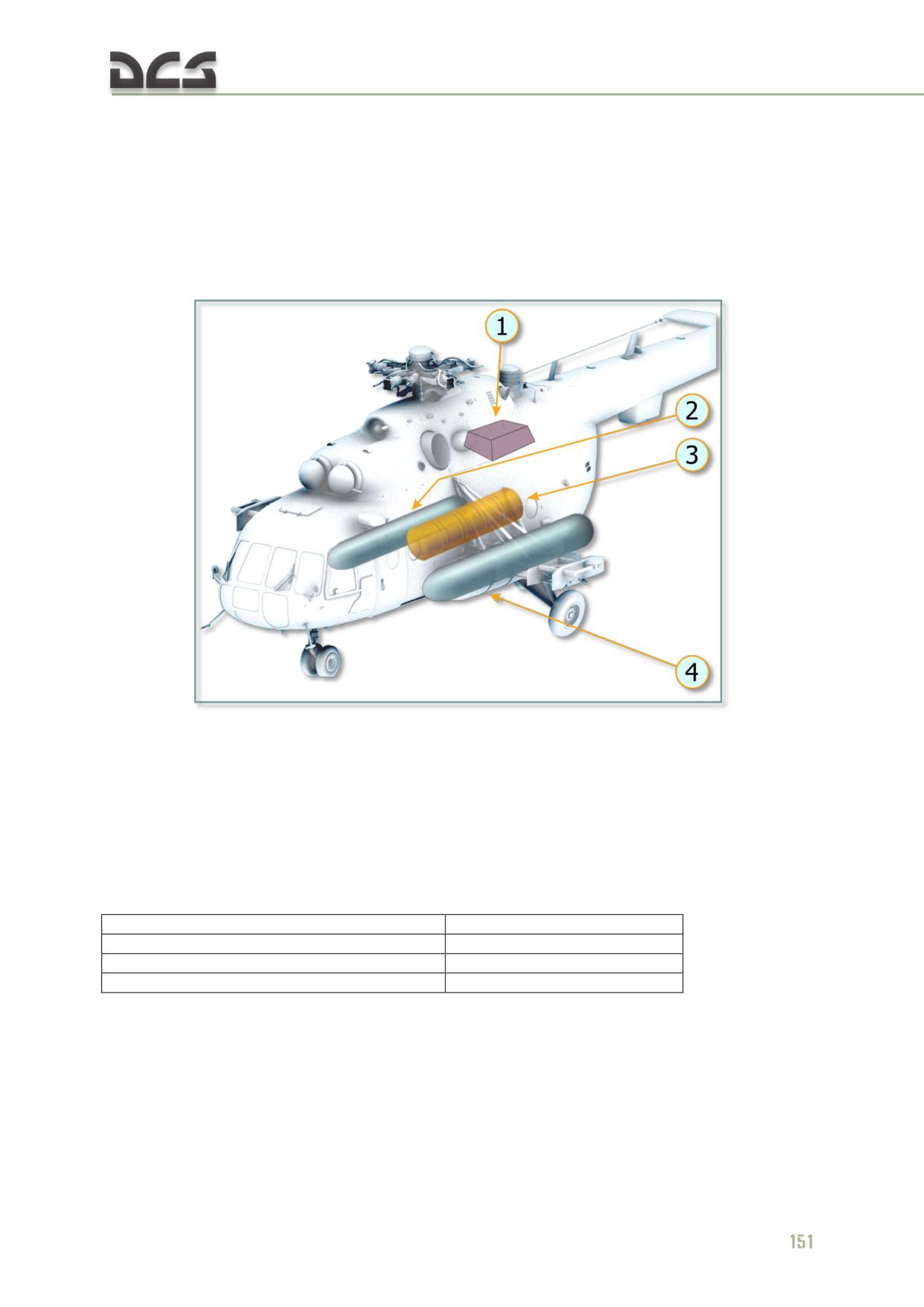
one service fuel cell is located in container behind main gear, Fig. 7.5
Fig. 7.5. Location of Fuel Systems Units
1. Service fuel cell
3. Left auxiliary tank (not implemented in the
2. Right saddle tank
simulator)
4. Left saddle tank
For increase in flight range and duration, one or two auxiliary fuel tanks may be
installed inside fuselage (not implemented in the simulator).
Fuel tanks capacity in ltr/kg:
service fuel cell with foam-filled
415/322
right saddle tank with foam-filled
1040/832
left saddle tank with foam-filled
1130/904
auxiliary tank with foam-filled
895/694 (not modeled)
7.2.2. Fuel Distribution System
Reliable operation of fuel system is ensured by pumps, valves, pressure sensors,
solenoid and shut-off valves, Fig. 7.6
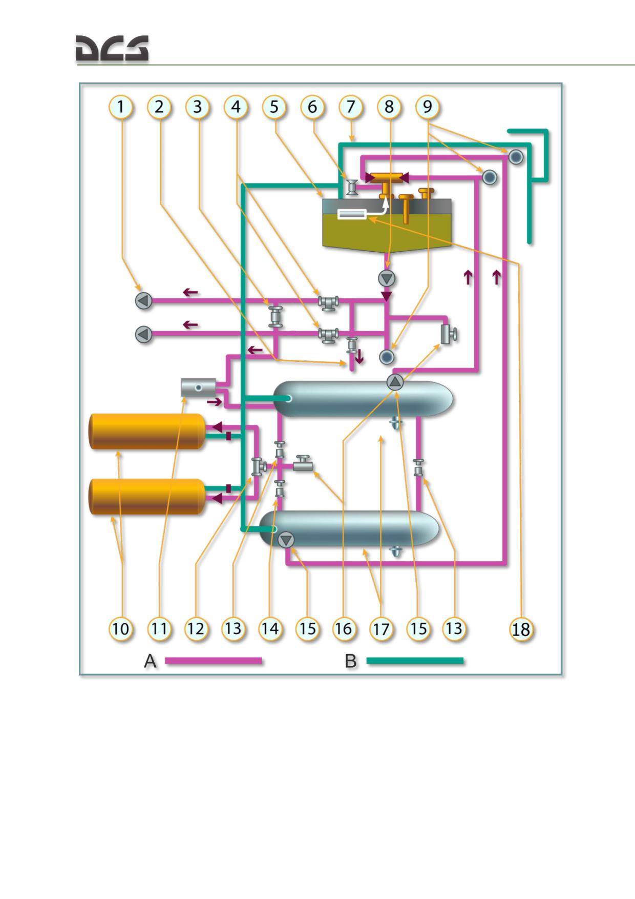
Fig. 7.6. Fuel System Diagram
1. Pumps of engines ДЦН-70А,
10. Auxiliary tanks (not implemented in the
2. Line to engine АИ-9В, with cock 610200А
simulator)
3. Solenoid valve 610200А КО-50
11. Kerosene-combustion heater КО-50
4. Emergency shut-off cock 768600МА
12. Bypass cock 637000
(electrical)
13. Shut-off cocks 768600МА
5. Service fuel cell
14. Shut-off cock 633600А
6. Shut-off cock 768600МА of fuel bypass line
15. Pumps ЭЦН-91
152
7. Breating line
16. Drain valves
8. Pump 463Б
17. Saddle tanks
9. Pressure detectors СД-29А
18. Float valve 766300А-1
A - Fuel feed line
B - Breathing lines
Helicopter fuel distribution system comprises the following: electric driven centrifugal
fuel pump 463Б (8); two centrifugal fuel pumps ЭЦН91С (15); electric driven fuel
pump 748Б (of heater КО-50, not shown); float valve 766300A-1 (18); five shut-off
cocks 768600MA (6, 13); one shut-off cock 633600A (14); two solenoid valves
610200А (2, 3) for feed lines of engine АИ-9 and heater КО-50 accordingly; bypass
cock 637000 (12); fuel filter 11 ТФ30 СТ (not shown); check valves block (not
shown); pipes and hoses.
From saddle tanks, fuel is fed to service fuel cell by two pumps ЭЦН-91С (15) via
pipelines; pump 463Б (8) distributes fuel from service fuel cell for feeding of engines
ТВ3-117ВМ. In the lines running from pump 463Б to engines, emergency shut-off
cocks 768600 МА (4) are fitted.
For feeding of engine АИ-9В and kerosene-combustion heater fuel is taken from the
line running to the right engine ТВ3-117ВМ, upstream the emergency shut-off cock.
This scheme (Fig. 7.6) does not contain the engines fuel shutoff levers, which are
opened / closed by crew for engines start / shut down.
Function of Fuel System Units
ELECTRIC DRIVEN CENTRIFUGAL FUEL PUMP 463Б (8) creates fuel overpressure at the inlet of main
fuel pumps of engines ТВ3-117ВМ and engine АИ-9В, and inlet of kerosene-combustion heater КО-50
pump 748Б as well.
Pump 463Б is located outside service fuel cell, in its lower part.
Pump 463Б failure does not lead to interruption of engines operation: fuel would be fed from service
fuel cells to engines by gravity.
Pump power supply circuit is connected to battery bus via circuit breaker ТОПЛИВНАЯ СИСТЕМА.
НАСОСЫ ТОПЛИВН. БАКОВ-РАСХОД (FUEL SYSTEM. FUEL TANKS PUMPS - FLOW) located on the
breakers’ right section of cockpit electric panel.
Pump is activated by switch НАСОСЫ БАКОВ-РАСХОД (TANKS PUMPS - FLOW) installed on the mid
section of electric panel.
ELECTRIC DRIVEN CENTRIFUGAL PUMPS ЭЦН-91С (15) located in the mounting units inside saddle
tanks (in the front part of left tank and in the rear part of right tank) pump fuel to service fuel cell.
Pumps motors power supply circuits are connected to battery bus via circuit breakers ТОПЛИВНАЯ
СИСТЕМА. НАСОСЫ ТОПЛИВН. БАКОВ-ЛЕВОГО (FUEL SYSTEM. FUEL TANKS PUMPS - LEFT) and
ТОПЛИВНАЯ СИСТЕМА. НАСОСЫ ТОПЛИВН. БАКОВ-ПРАВОГО (FUEL SYSTEM. FUEL TANKS PUMPS
- RIGHT) on the breakers’ right section of cockpit electric panel. Pumps are turned on by switches
НАСОСЫ БАКОВ-ЛЕВЫЙ (TANKS PUMPS - LEFT) and НАСОСЫ БАКОВ-ПРАВЫЙ (TANKS PUMPS -
RIGHT), on the mid section of cockpit electric panel.
ELECTRIC DRIVEN FUEL PUMP 748Б (11) of geared type for fuel feed to kerosene-combustion heater
КО-50 injectors, installed in kerosene-combustion heater bay.
Pump power supply and control circuit is connected to rectifier bus via circuit breaker of heater КО-50,
located on the breakers right section of cockpit electric panel. Pump activates after heater activation.
FLOAT VALVE 766300А-1 (18) prevents overfill of service fuel cell when fuel is pumped from saddle
tanks; it is installed in service fuel cell and fixed to its plate.
During pumping, when service fuel cell is not yet filled completely, valve goes off its seat under fuel
pressure thus opening passage area for fuel flow. Fuel goes to the tank via valve body openings and
fills the tank. After tank is filled the valve float takes top position and shuts fuel supply to the tank.
EMERGENCY SHUT-OFF COCKS 768600А (4) are operated remotely via electric circuits; they serve
for shutting and opening of fuel lines. The Emergency Shut-off Cocks inslalled in the main gear part
(see Fig. 7.7 1, 2). Designed to shutoff of fuel lines in case of fire.
Emergency shut-off cocks power supply circuits are connected to battery bus via circuit breakers
ТОПЛИВНАЯ СИСТЕМА. ПЕРЕКРЫВ. КРАНЫ-ЛЕВЫЙ (FUEL SYSTEM. SHUT-OFF COCKS - LEFT) and
ТОПЛИВНАЯ СИСТЕМА. ПЕРЕКРЫВ. КРАНЫ-ПРАВЫЙ (FUEL SYSTEM. SHUT-OFF COCKS - RIGHT) on
the breakers’ right section of cockpit electric panel. The cocks are opened and shut by switches
ПЕРЕКРЫВ. КРАНЫ-ЛЕВЫЙ (SHUT-OFF COCKS - LEFT) and ПЕРЕКРЫВ. КРАНЫ-ПРАВЫЙ (SHUT-OFF
COCKS - RIGHT), which are located on the electric panel mid section and safeguarded. Shut position
of cocks is indicated by lamps ЛЕВЫЙ ЗАКРЫТ (LEFT SHUT) and ПРАВЫЙ ЗАКРЫТ (RIGHT SHUT),
located below those switches.
TWO FUEL SHUTOFF LEVERS are installed in the fuel lines of engines TV3-117VM, they cut off fuel
(handle) flow upstream engines inlet. It necessary open/close in case start/stop engines by crew
members.
ONE SHUT-OFF COCK (6) serves for fuel bypassing from saddle tanks to service fuel cell in case of
failure of float valve 766300А-1 in shut position. The cock is installed on the service fuel cell plate.
Shut-off cock power supply circuit is connected to battery bus via circuit breaker ТОПЛИВНАЯ
СИСТЕМА-КРАН ПЕРЕПУСК (FUEL SYSTEM - BYPASS COCK) located on the right section of cockpit
electric panel. The cock is opened and shut by switch ТОПЛИВНАЯ СИСТЕМА-ПЕРЕПУСК FUEL
SYSTEM - BYPASS) located on the mid section of electric panel.
TWO SHUT-OFF COCKS are installed in tanks cross-feeding lines that interconnect saddle tanks in
their front and rear parts. They serve for uniform fuel use from saddle tanks in case of failure of either
pump ЭЦН-91С.
Normal position of cocks is open.
The cocks shall be shut when helicopter enters hazardous zone, to save fuel in one saddle tank if
another gets damaged.
Cross-feeding cocks power supply circuits are connected to battery bus. The cocks are opened and
shut by safeguarded switch КОЛЬЦЕВ БАКОВ ЗАКР-ОТКР (TANKS CROSS-FEEDING OPEN-SHUT)
located on the mid section of electric panel. Shut position of cocks is indicated by yellow lamp
КОЛЬЦЕВ ОТКЛ. (CROSS-FEEDING OFF) below the switch.
SHUT-OFF COCK 633630 (not implemented in the simulator) shuts front cross-feeding line. The cock
is controlled manually and should be open. The cock is shut in case of right tank removal and fuel
drain from auxiliary tanks.
SOLENOID VALVES 610200А ensure control of fuel feed to engine АИ-9В and kerosene-combustion
heater КО-50. The solenoid valve in the fuel line of engine АИ-9В is installed in the main gear
compartment. It opens automatically after start button of engine АИ-9В is pressed. Cock closes when
engine АИ-9В shuts down.
The solenoid valve in the fuel feed line of kerosene-combustion heater КО-50 is installed on the cargo
compartment ceiling panel below emergency shut-off cock; it opens automatically when heater is
started and shuts when heater is turned off.
BYPASS COCK 637000 (not implemented in the simulator) serves for connection of one or two
auxiliary tanks to the front line connecting the saddle tanks, and for fuel drain from auxiliary tanks.
154
The cock is opened manually. It is installed under cargo compartment deck close to shut-off cock
633600А. The cock ensures fuel use from auxiliary tanks: either separate or simultaneous.
CHECK VALVES BLOCK includes two check valves installed in the lines of fuel transfer from saddle
tanks to service fuel cell. The valves pass fuel in one direction only - to service fuel cell. They are
installed on the service fuel cell plate upstream float valve and shut-off cock.
The system of pipelines and check valves ensures fuel feed of engines from either pump of saddle
tanks, if another fails.
PRESSURE DETECTORS СД-29А (SD-29A) turn off the lamps, which indicate running of transfer
pumps ЭЦН-91С or pump 463Б if pressure in relevant line drops below 0.5 kg/cm².
7.2.3. Monitoring and Control of Fuel System Operation
Fuel System Units Control
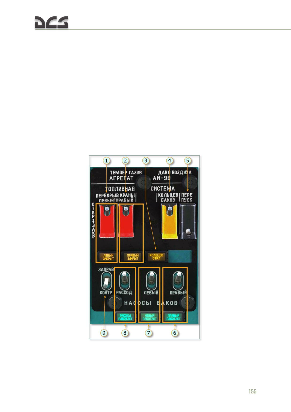
The units of fuel system are controlled from the fuel system control panel located on
the mid section of electric panel, Fig. 7.7. Moreover, there are manual shut-off cocks
that are not implemented in the simulator.
Fig. 7.7. Fuel System Control Panel, Center overhead console
1. Indicator lamp of left fuel shut-off cock and
6. Switch and indicator lamp of RIGHT tank
its closed position
ЭЦН-91С pump operating status
2. Indicator lamp of right fuel shut-off cock
7. Switch and indicator lamp of LEFT tank
and its closed position
ЭЦН-91С pump operating status
3. Indicator lamp of fuel cross-feeding
8. Switch and indicator lamp of FEED tank
disabling (interconnecting line is shut)
463Б pump operating status
4. Switch of saddle tanks cross-feed enabling
9. Switch for selecting operating mode of
solenoid valves (top position: interconnecting
lamps indicating 100% fill of tanks. The lamps
line is open - ОТКРЫТА)
are located close to fillers, not implemented in
5. Switch of solenoid valve for manual fuel
the simulator
bypassing from saddle tanks to service fuel
cell (in case of service fuel cell float valve
failure). Normal position is ЗАКРЫТО
(CLOSED) - down
Fuel System Operation Monitoring
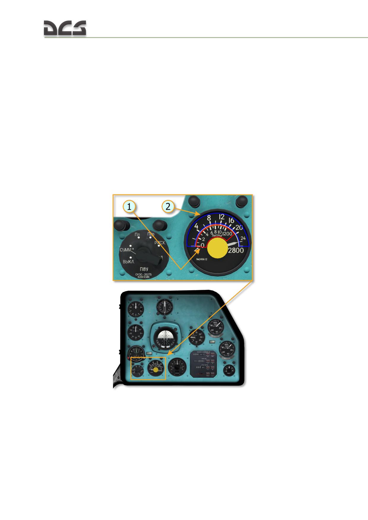
Operation of fuel system may be monitored by pumps’ indicator lamps and fuel
gauge, which indicates remaining fuel quantity in litres, separately or in total (for
saddle tanks and service fuel cell), Fig. 7.8:
Fig. 7.8. Fuel gauge
1. Inner scale, for reading of fuel quantity in
2. Outer scale for reading total fuel quantity
separate tanks (highlighted red)
(highlighted blue)
For tanks switching over, fuel gauge switch, Fig. 7.9 is used:
156
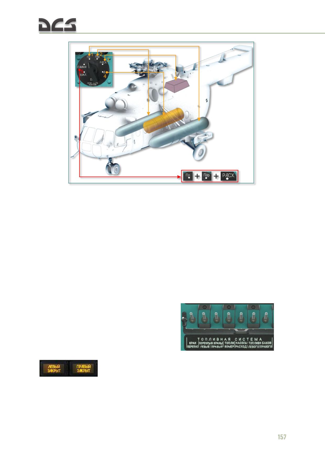
Fig. 7.9. Fuel Gauge Switch
Fuel gauge switch positions
3. РАСХ - Service fuel cell
1. Пл - Left Saddle tank
4. Д - Auxiliary Tank (not implemented in the
2. Ппр - Right Saddle tank
simulator)
5. СУММА - total fuel quantity in saddle tanks
and service fuel cells
7.2.4. Normal Operation
Before Start
1. Set the following circuit breakers to on: ТОПЛИВНАЯ СИСТЕМА.
ТОПЛИВОМЕР (FUEL SYS FUEL GAUGE); НАСОСЫ ТОПЛИВН. БАКОВ-РАСХОД-
ЛЕВОГО-ПРАВОГО (FUEL TANKS PUMPS - FLOW - LEFT - RIGHT); ПЕРЕКРЫВ
КРАНЫ ЛЕВЫЙ-ПРАВЫЙ (SHUT-OFF COCKS LEFT - RIGHT), КРАН ПЕРЕПУС.
(BYPASS COCK) on the breakers’ mid section
. At
that, lamps ЛЕВЫЙ ЗАКРЫТ (LEFT CLOSED), ПРАВЫЙ ЗАКРЫТ (RIGHT CLOSED)
on the mid section of electric panel come on (Fig. 7.7, 1, 2);
2. Check fuel quantity using fuel gauge indicator;
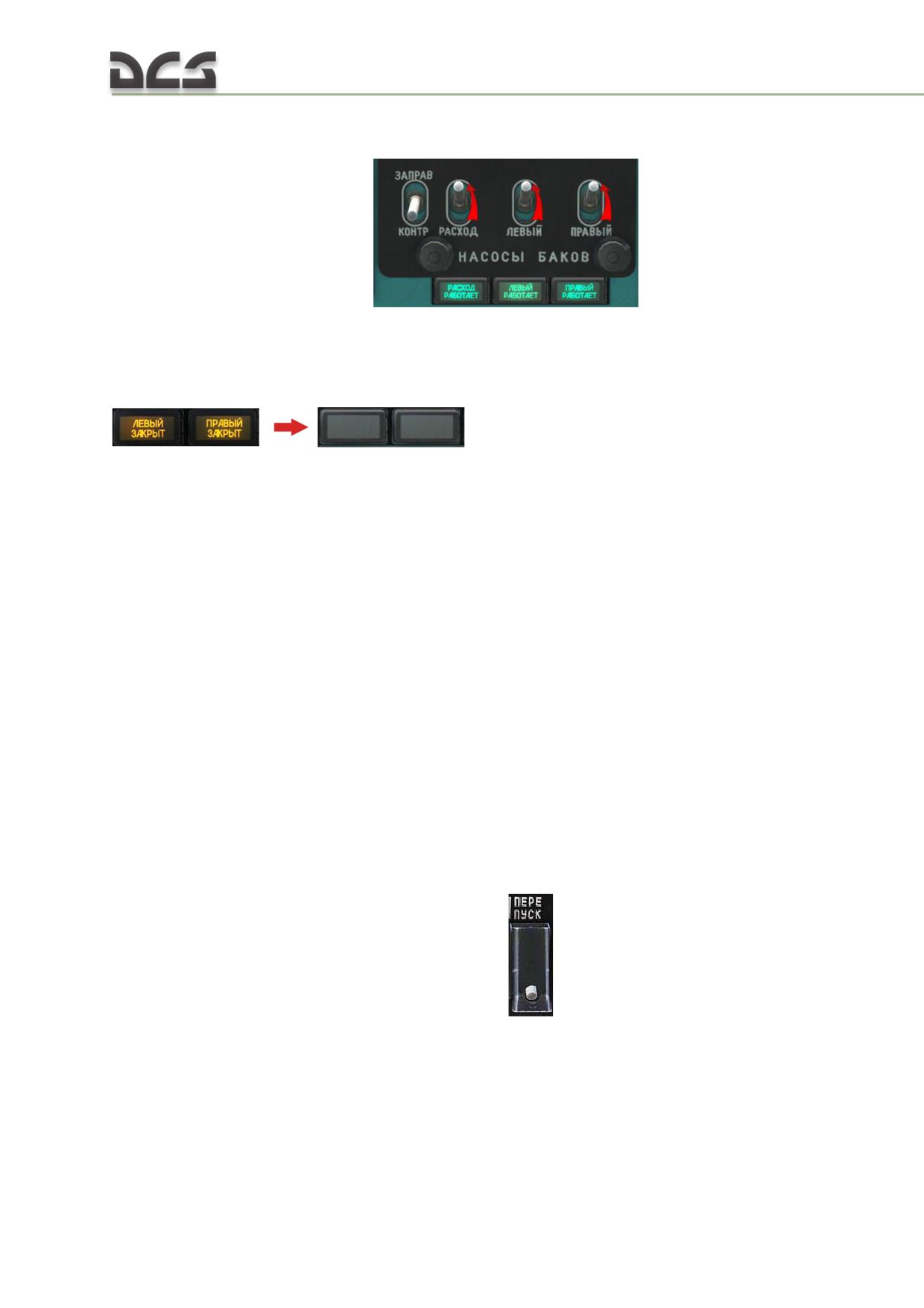
3. Check functioning of backing up and transfer pumps by alternate training of
them: make sure that lamps РАСХОД РАБОТАЕТ (FLOW ON), ЛЕВЫЙ (ПРАВЫЙ)
РАБОТАЕТ (LEFT (RIGHT) ON)
come on;
4. Prior to starting auxiliary power unit and main engine, turn on the fuel
gauge, backing up and transfer pumps to check functioning of them by relevant
indicator lamps coming on; open emergency shut-off cocks: indicator lamps ЛЕВЫЙ
ЗАКРЫТ (LEFT CLOSED) and ПРАВЫЙ ЗАКРЫТ (RIGHT CLOSED)
must go off.
Operation in Flight
Fuel pumped from outboard pumps goes to service fuel cells by two fuel lines via
check valves and float valve; from service fuel cell, fuel is fed to engines ТВЗ-117ВМ
via open emergency shut-off cocks.
In flight, it is required to monitor lamp indicating pumps operation and remaining
fuel in service fuel cell (once in 5 to 10 min).
7.2.5. Failures
Indications of failure and appropriate actions.
Failure of service fuel cell float valve (not implemented)
Failure of service fuel cell float valve has the following indication:
with saddle tanks’ pumps running, fuel quantity in service fuel cell
decreases.
Crew Procedure
Take decision about continuing flight.
Set switch ПЕРЕПУСК (BYPASS)
on the panel ТОПЛИВНАЯ
СИСТЕМА (FUEL SYSTEM) (Fig. 7.7, 5) to ОТКР. (OPEN, up): fuel will be
delivered to service fuel cell through open shut-off cock, with float valve
bypassing. Then, further fuel use should be adjusted manually while
maintaining fuel quantity in service fuel cell at the level of 370...390 litres
and avoiding its overfill.
158
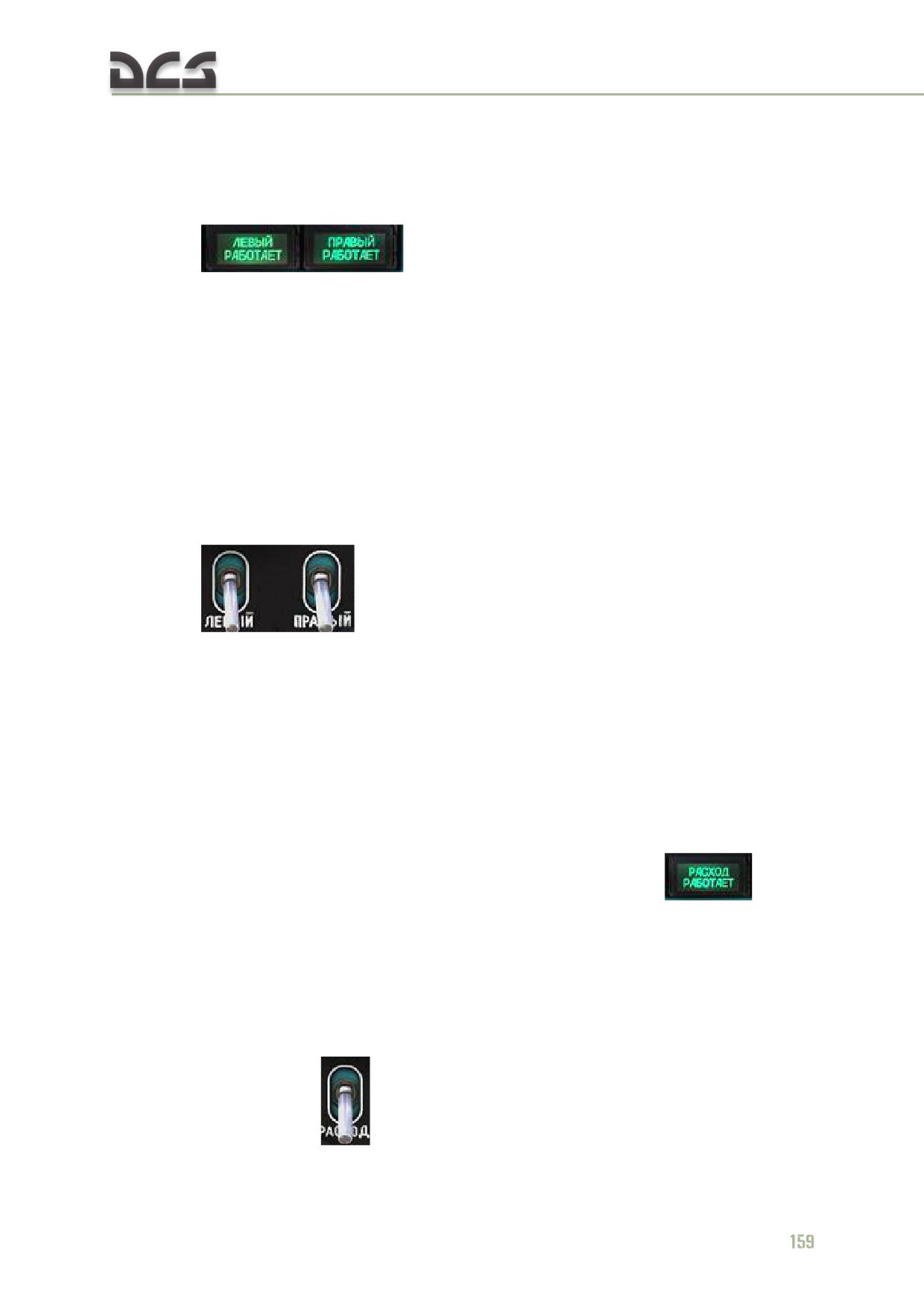
Failure of One/Both Transfer Pump
Failure of transfer pumps has the following indications:
indcator lamp НАСОСЫ БАКОВ (TANKS PUMPS): ЛЕВЫЙ РАБОТАЕТ
(LEFT RUNNING) or ПРАВЫЙ РАБОТАЕТ (RIGHT RUNNING)
goes off, or both lamps go off;
voice recorder message "Отказали насосы основных топливных баков"
(Main fuel tanks’ pumps failure);
fuel quantity reduction in service fuel cell.
Crew Procedure
IF ONE TRANSFER PUMP FAILS:
Turn off the failed pump.
In case of either pump failure, another pump ensures service fuel cell fill.
Make sure that fuel is fed to service tank and continue your mission.
IF BOTH TRANSFER PUMPS FAIL:
Turn off НАСОСЫ БАКОВ ЛЕВЫЙ, ПРАВЫЙ (TANKS PUMPS LEFT, RIGHT)
Abort the mission.
Land on the nearest airfield or an appropriate site noticed in flight.
WARNING. Please note that fuel quantity in service fuel cell is sufficient for flight at altitude 500 m
and speed 220 km/h for 21 min to the range of 70 km.
Service fuel cell Backing Pump Failure
Failure of service fuel cell backing pump has the following indications:
short-term drop of engines RPM by 2-5%, fuel pressure by 3-4 kgf/cm²
and main rotor RPM by 1-3%;
green indicator lamp РАСХОД РАБОТАЕТ (FLOW ON)
on the
mid section of electric panel goes off;
voice recorder message "Отказал насос расходного бака" (Service fuel
cell pump fails).
Crew Procedure
if backing pump fails, continue the mission. At that, normal operation of
engines are ensured by pumps of engine ДЦН-70А.
turn pump off
act smoothly when changing engine operating parameters and helicopter
piloting.
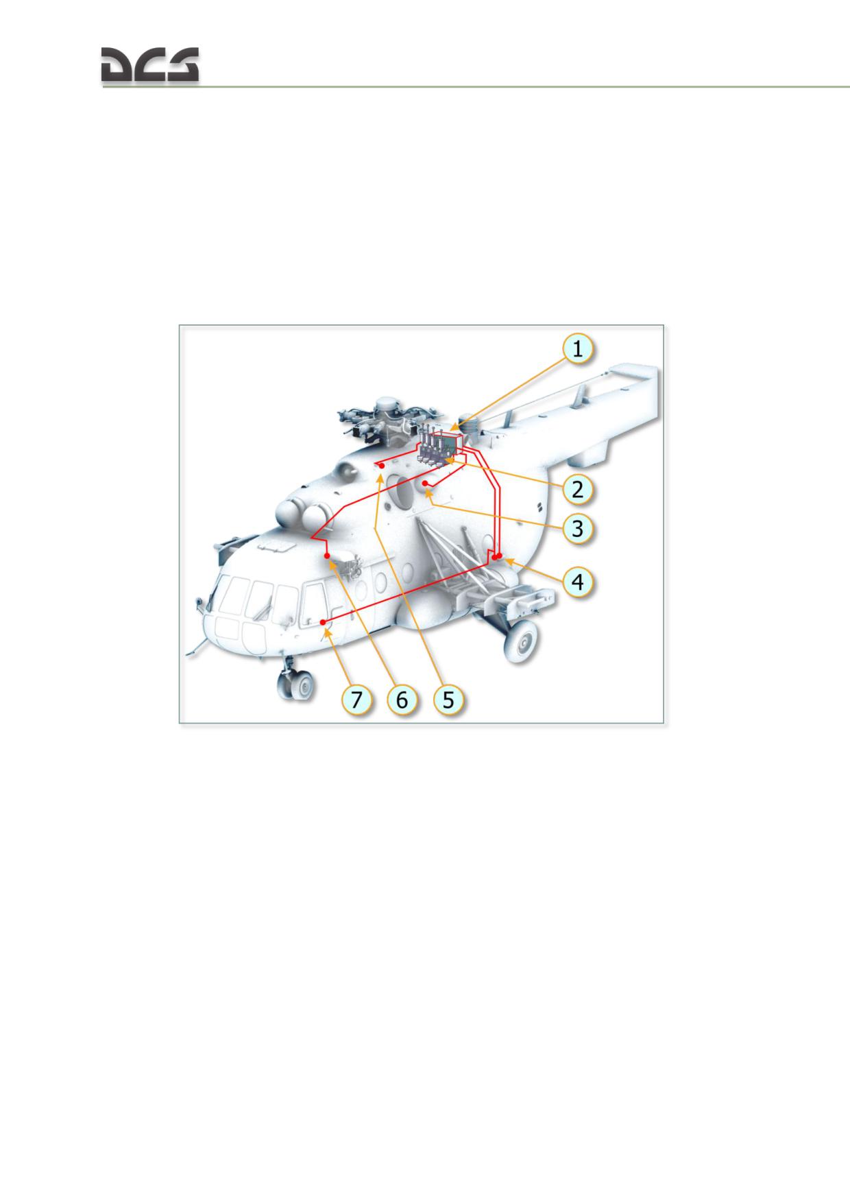
7.3. Hydraulic System
7.3.1. Brief Description
Helicopter has two independent hydraulic systems:
main system;
backup system
Fig. 7.10. Location of Hydraulic System Units
1. Hydraulic units’ panel
5. Backup system hydraulic pump НШ-39М
2. Hydraulic boosters
6. Hydraulic lock cylinder
3. Main system hydraulic pump НШ-39М
7. Collective pitch control clutch dumping
4. Charging connections panel
cylinder
(1) HYDRAULIC UNITS CYLINDER serves for compact location of both hydraulic systems
units (solenoid valves, pressure accumulators, filters, check valves);
(2) HYDRAULIC BOOSTERS convert manual control rods motion autopilot signals into
power rod travel;
(3) HYDRAULIC PUMP НШ-39М of main system serves for creation of pressure in main
system line;
(4) CHARGING CONNECTIONS PANEL is used for charging of hydraulic systems with power
fluid and check of those system from ground unit (not implemented in the
simulator);
160
(5) HYDRAULIC PUMP НШ-39М of backup system serves for creation of pressure in
backup system line;
(6) HYDRAULIC LOCK CYLINDER serves for force creation on cyclic pitch control stick
when swash plate angle reaches 2°12'. Force makes 16 kg (not implemented in the
simulator);
(7) COLLECTIVE PITCH CONTROL CLUTCH DUMPING CYLINDER serves for release of collective
pitch control forces, when pressing on collective pitch control button (not
implemented in the simulator)
Main Hydraulic System
Main hydraulic system serves for feeding of combined control units (hydraulic
boosters) КАУ-30Б (KAU-30B, installed in longitudinal, lateral and collective pitch
control systems) and РА-60Б (RA-60B, lateral control system), collective pitch control
clutch dumping cylinder, variable lock cylinder (lateral control).
Hydraulic boosters КАУ-30Б and РА-60Б can operate in two modes:
manual control (by pilot);
combined control (autopilot on).
Backup Hydraulic System
Backup hydraulic system duplicates main hydraulic system; it performs main system
functions if that fails. Backup system is activated automatically, if main system
pressure drops to 30±5 kgf/cm².
In case of main system failure and backup system activation, the following units are
deactivated automatically: autopilot АП-34Б (AP-34B), collective pitch control clutch
dumping system and hydraulic lock. At that, hydraulic boosters are operated in
manual mode only; to create optimum forces for collective pitch control movement,
clutch tightening is to be adjusted (not implemented in the simulator).
Control of Hydraulic Systems
Hydraulic systems are controlled from hydraulic system panel, Fig. 7.11
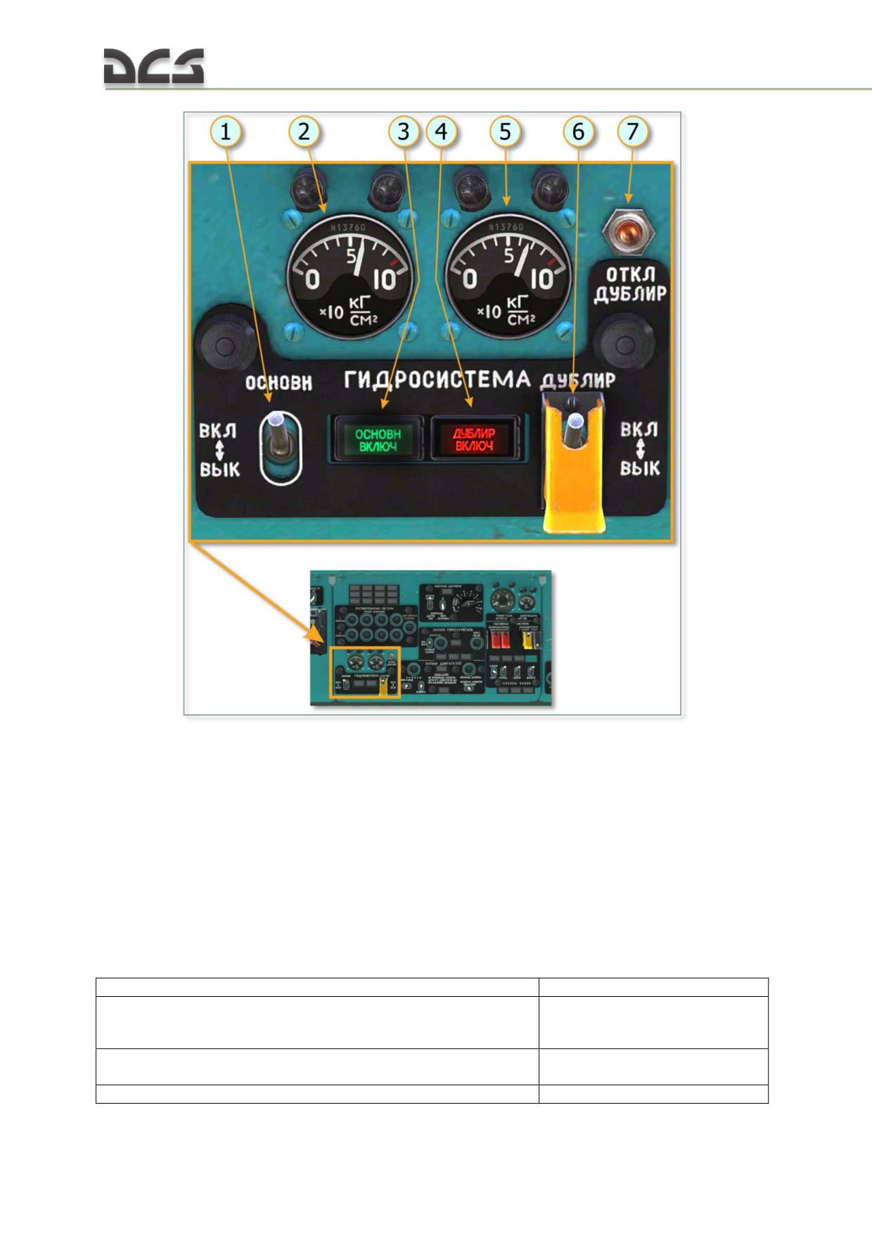
Fig. 7.11. Hydraulic System Control Panel
1. Main system switch
5. Backup system pressure gauge
2. Main system pressure gauge
6. Backup system switch
3. Lamp indicating activation of main system
7. Backup system deactivation button
4. Lamp indicating activation of backup system
Button ОТКЛ.ДУБЛИР. (DEACTIVATE BACKUP SYS) (Fig.
7.11,
7) for stable
switching from backup system to main one during engine start and hydraulic system
ground check (ground check is not implemented in the simulator).
Technical details of hydraulic systems are given in Table 7.1.
Table 7.1
Power fluid
масло АМГ-10
Operating pressure in main and backup hydraulic systems
(4500± 300...650
) kPa
[(45±3…6
) kgf/cm2]
2
Ambient air operation range for normal operation of hydraulic
от -50 до +60 °С
systems
Power fluid permissible temperature
до 70°С
162
АМГ-10 oil quantity in hydraulic system
22 l (по 11)
System pressure for pump switching to operating mode
(4500±300) kРа [(45±3)
(hydraulic system feeding)
kgf/cm2]
System pressure of pump switching to idle mode (fluid pumping
(650
) kРа [(6
)
200
2
to tank)
kgf/cm2]
Minimum pressure in main system for hydraulic boosters feed
(3000±500) kPa [(30±5)
switching to backup system
kgf/cm2]
7.3.2. Normal Operation
Check before starting the engine
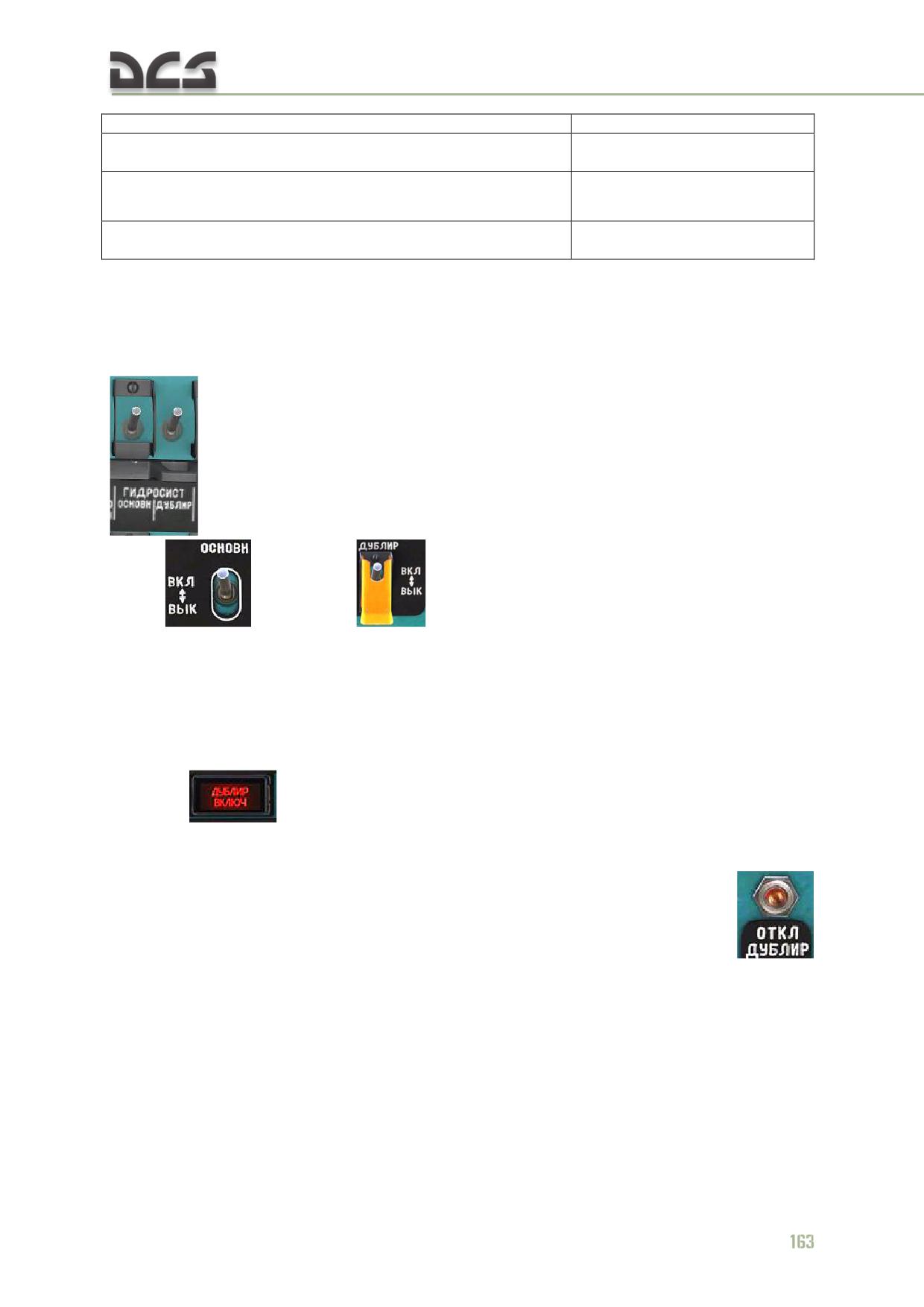
Set circuit breakers ГИДРОСИСТ. ОСНОВН/ДУБЛИР. (HYDRO SYS MAIN/BACKUP)
to on. Make sure that hydraulic systems switches are set to ВКЛ (ON)
(main
and backup
hydraulic systems are activated), and backup
system switch ГИДРОСИСТЕМА ДУБЛИР. (HYDRO SYS BACKUP) is safeguarded.
During Engine Start
Warning! During engine start with main and backup systems switches set to on,
backup system may activate (not main one). At backup system pressure of
(2500±160) kPa [(25±1.6) kgf/cm²] indicator lamp ДУБЛИР ВКЛЮЧЕНА (BACKUP
SYS ON)
must come on. (At that, electromagnetic relay deactivates main
hydraulic system). Pressure read by pressure gauges of both systems will be
stabilized within (6500) kPa [(65) kgf/cm²]. To switch to operation from main
hydraulic system, press button ОТКЛ ДУБЛИР (DEACTIVATE BACKUP SYS)
and hold it for 1…1.5 s. Indicator lamp ОСНОВНАЯ ВКЛЮЧЕНА (MAIN SYS ON)
must come on and indicator lamp ДУБЛИР ВКЛЮЧЕНА (BACKUP SYS ON) must go
off. Pressure in backup system shall drop to (0-500) kPa [(0-5) kgf/cm²].
Prior to hydraulic system serviceability check, it is required to switch to main system;
for that, press button ОТКЛ. ДУБЛИР. (DEACTIVATE BACKUP SYS) on the mid
section of cockpit electric panel and hold it until green indicator lamp ОСНОВН.
ВКЛЮЧ. (MAIN SYS ON)
comes on and red indicator lamp ДУБЛИР.
ВКЛЮЧ. (BACKUP SYS ON) goes off.
Make sure that main system pressure increases to 42... 73 kgf/cm²
. At
that, one should pay attention to frequency of main system pressure gauge indicator
movement.
Hydraulic System Check During Power Plant Warm-up
Check operation of hydraulic system controls; for that:
deflect control stick, pedals and collective pitch control lever alternately,
by no more than 1/3 of their full travel, to make sure that controls operate
smoothly (no jerks or sticking);
make sure that operation of controls causes main system pressure
variation within 42...73 kgf/cm², no pressure in backup system, green
indicator lamp ОСНОВН. ВКЛЮЧЕНА (MAIN SYS ON) is on;
Set switch (MAIN HYDRO SYS) to ВЫКЛ (OFF). Pressure in main system
(downstream valve) will drop to zero; at the moment it passes the value
(3000±160) kPa [(30±1.6) kgf/cm²] main system pressure detector will
operate, indicator lamp ОСНОВНАЯ ВКЛЮЧЕНА (MAIN SYS ON) goes off;
when pressure becomes (3000±500) kPa [(30±5) kgf/cm²] emergency
feeding valve will operate. Pressure in backup system must go up; when
pressure reaches (2500±1.6) kPa [(25±1.6) kgf/cm²] the backup system
pressure detector will operate and indicator lamp ДУБЛИР ВКЛЮЧЕНА
(BACKUP SYS ON) must come on. Pressure in backup system grows
800
rapidly and changes within (4500±300...6500
) kPa [(45±3...6
)
200
2
kgf/cm²], when controls are moved;
set main system switch to on and make sure that green indicator lamp
ОСНОВН. ВКЛЮЧЕНА (MAIN SYS ON) comes on, pressure in main system
is maintained within
42…73 kgf/cm², red indicator lamp ДУБЛИР.
ВКЛЮЧЕНА (BACKUP SYS ON) goes off and pressure in backup system
drops to zero. For the helicopters with updated electric circuit of hydraulic
system: to switch to main system, after setting ГИДРОСИСТЕМА ОСНОВН
(HYDRO SYS MAIN) to on, it is required to press button ОТКЛ. ДУБЛИР.
(DEACTIVATE BACKUP SYS) on the mid section of cockpit electric panel
and hold it until green indicator lamp ОСНОВН. ВКЛЮЧЕНА (MAIN SYS
ON) comes on and red indicator lamp ДУБЛИР. ВКЛЮЧЕНА. (BACKUP
SYS ON) goes off.
7.3.3. Failures
For indications of failures and appropriate actions refer to 10.7
164
7.4. Anti-Ice System
7.4.1. General Description
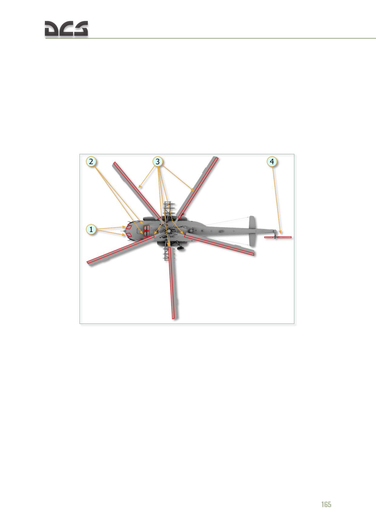
Helicopter Anti-Ice System serves for icing prevention and ice/water removal from
helicopter units (Fig. 7.12) and indication of icing as well. The protected elements
are as follows:
two front glasses of cockpit;
air intakes including air inlet Particle Separator System (PSS) and engines’
inlets;
main and tail rotor blades.
Fig. 7.12. Anti-Ice System
1. Heated glasses
3. Heated parts of main rotor blades
2. Heated parts of air intakes including Particle
4. Heated parts of tail rotor blades
Separator System and engines’ inlets
For icing early warning, helicopter is furnished with ice detector РИО-3 and visual ice
detector.
7.4.2. Heated Glasses
Glasses are electrically heated.
Anti-ice system of glasses provides for automatic energizing of glasses heating by
СО-121ВМ ice detector signal and manual switching to glasses heating and wipers
also. Glasses heating temperature (30°С) is maintained by temperature regulators
ТЭР-1М.
Technical details of heated glasses:
Supply voltage, V
190; 208; 230 or 250
Power demand, W, max.
1930
Current consumption, A, max.
9.65
For adjustment of currents consumed by glasses heating elements, rotary switch
ТОКИ ПОТРЕБИТЕЛЕЙ (CONSUMERS CURRENTS) (Fig. 7.18) is to be set to
ОБОГРЕВ СТЕКОЛ (GLASSES HEATING), along with current check by dashboard
amperemeter. Dashboard amperemeter readings should be within 40-120 A. Current
value depends upon simultaneous energizing of glasses heating. To know true value
of current, amperemeter readings should be divided by 6.
Wipers
Heated glasses are equipped with wipers. Wipers serve for removal of water splashes
and snow off cockpit heated glasses. Wiper brushes are actuated directly with
electric actuators ЭПК-2Т-60.
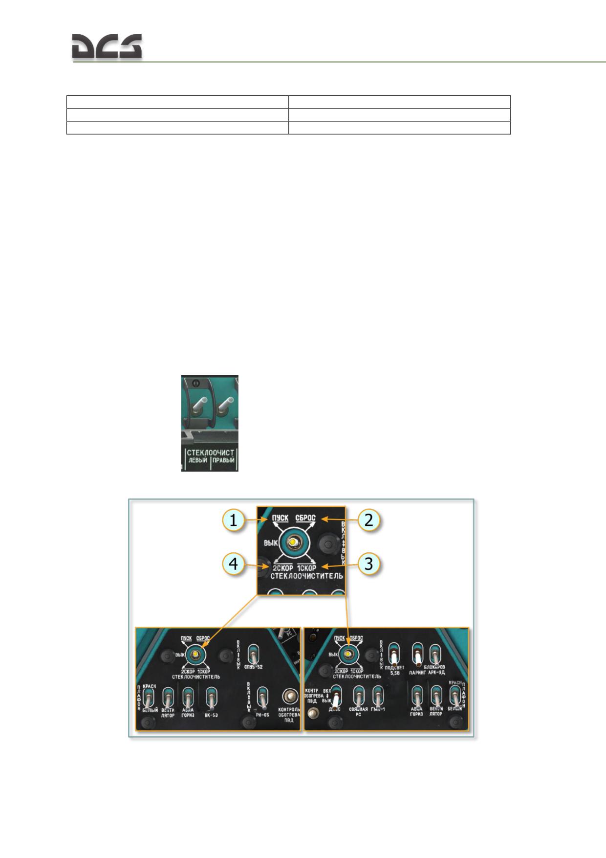
Electric actuator ЭПК-2Т-60 has four modes of operation: starting mode; the first
speed; the second speed; brush return to initial position.
Wipers supply and control circuit is connected to battery bus via circuit breakers (CB)
СТЕКЛООЧИСТ. - ЛЕВЫЙ (WIPER - RIGHT) and СТЕКЛООЧИСТ. - ПРАВЫЙ
(WIPER - RIGHT)
. For wiper control, СТЕКЛООЧИСТИТЕЛЬ (WIPER)
switches on the left and right section of the electric panel are used, Fig. 7.13
Fig. 7.13. Position of switch СТЕКЛООЧИСТИТЕЛЬ (WIPER)
166

1. ПУСК (START) - starting operation, the
3. 1 СКОР (SPEED 1) - switch position for first
switch should be set to this position, for a
speed operation
short time
4. 2 СКОР (SPEED 2) - switch position for
2. СБРОС (RESET) - position to stop operation
second speed operation
The switches have four fixed positions: ПУСК (START), 1 СКОР. (SPEED 1 - 60..90
oscillations per minute), 2 СКОР. (SPEED 2 - 30..60 oscillations per minute) and
neutral position corresponding to off position of electric actuator. The fifth position,
СБРОС (RESET) is not fixed; it provides automatic return to off position.
To start wiper operation, circuit breakers СТЕКЛООЧИСТИТЕЛЬ - ЛЕВЫЙ (WIPER -
RIGHT), СТЕКЛООЧИСТИТЕЛЬ - ПРАВЫЙ (WIPER - RIGHT) should be set to on.
Then set switch СТЕКЛООЧИСТИТЕЛЬ (WIPER) to ПУСК (START) position; then,
depending upon external conditions (rain or snow rate), the switches should be set
to position 1 СКОР (SPEED 1) or 2 СКОР (SPEED 2) (rain and snow on helicopter
glasses is not implemented in simulator yet).
In the game, this switch is controlled by the mouse: player must click on one of the
five areas, corresponding to operation modes of windshield wipers:
After wiper is switched off, brush may stop at any position and obstruct viewing. To
set it to initial limit position, switch СТЕКЛООЧИСТИТЕЛЬ (WIPER) should be set to
СБРОС (RESET) and held in that position until brush takes limit position; at that,
electric actuator will stop automatically. After wiper is stopped in limit position,
switch is to be released; when released, the switch takes neutral (off) position.
7.4.3. Anti-Ice System of air inlet Particle Separator System
Air inlet Particle Separator System (PSS) anti-icing system is of combined type (bleed
air plus electrical heating); engines’ inlets are heated by bleed air only.
Heating hot air is bled from combustor cooling loop (5), Fig. 7.14.
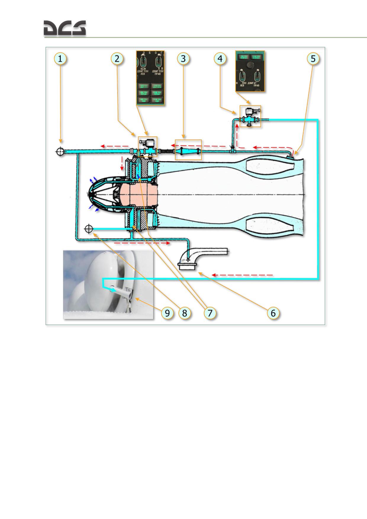
Fig. 7.14. Diagram of Hot Air Bleed for PSS and Engines’ Inlets anti-ice system
and for PSS Needs
1. Anti-ice system of air intake (intake lip)
5. Fitting for air bleed from ТВ3-117ВМ engine
2. Electric shutter 1919Т, which opens hot air
combustor cooling loop
flow for anti-ice system needs
6. Heating of НР-ЗВМ governor pump thermal
3. Temperature regulator
compensator air receiver (for correct operation
4. Electric shutter 1919Т, which opens hot air
of governor's systems)
flow to PSS ejector (for vacuum creation)
7. Heated parts of inlet guide vane (vertical
and horizontal supports)
8. Air bleed for PSS trap heating
9. PSS ejector
Either engine has shutter 1919Т (2), which opens hot air flow from combustor
cooling loop (5).
NOTE. The second shutter (4) serves for air supply to PSS ejector for creation of vacuum, which
promotes suction and ejection of dust from engine inlet duct.
168
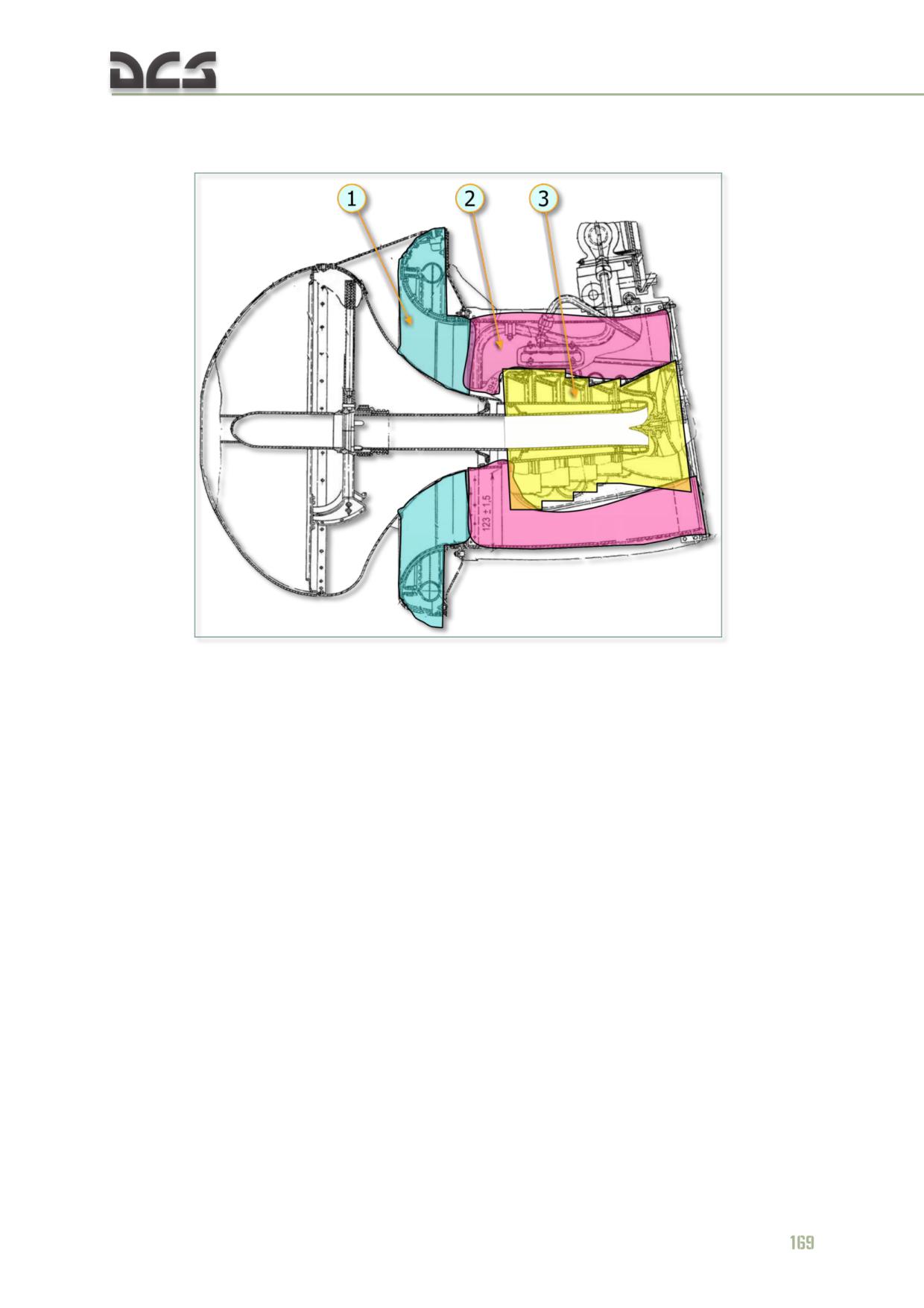
In PSS, the following surfaces are heated by hot air (Fig. 7.15): intake lip and duct
surface, PSS trap, НР-ЗВМ governor thermal compensator air receiver (Fig. 7.14, 6).
Fig. 7.15. PSS parts heated by hot air
1. Intake lip
3. PSS trap
2. Duct surface
Electrical heating (Fig. 7.16) is provided for the following units of PSS: fairing front
and back, dust removal pipeline casing, dust exhaust throat and noses of fairing
supports.
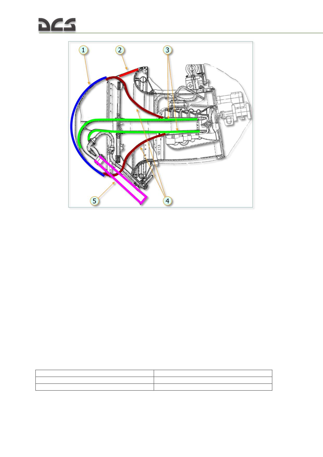
Fig. 7.16. PSS parts heated by heating elements
1. Fairing front
3. Dust removal pipeline casing
2. Nose of fairing support
4. Fairing back
5. Dust exhaust throat
Heating pads are pasted on the entire area of the said surfaces (inside or outside).
Between casing and heating pad, thermal sensors ТД-2 are pasted; those sensors
ensure stable temperature of heater under various temperatures of outside air, along
with temperature regulators ТЭР-1М.
Electric heating system is powered by 200 V AC, 400 Hz.
Heating of left engine, its air intake and PSS are energized and de-energized
manually, heating of right engine and its inlet components are energized both
manually and automatically from ice detector (see below). Heating is de-energized
manually.
Readings of dashboard amperemeter (Fig. 7.18) shall be within 65-120 A. Current
value depends upon simultaneous energizing of PSS front and back heating. To know
true value of current, amperemeter readings should be divided by 3.
Technical details of heating elements:
Supply voltage, V
200-208V
Power demand, W, max.
8000
Current consumption, A, max.
40
170
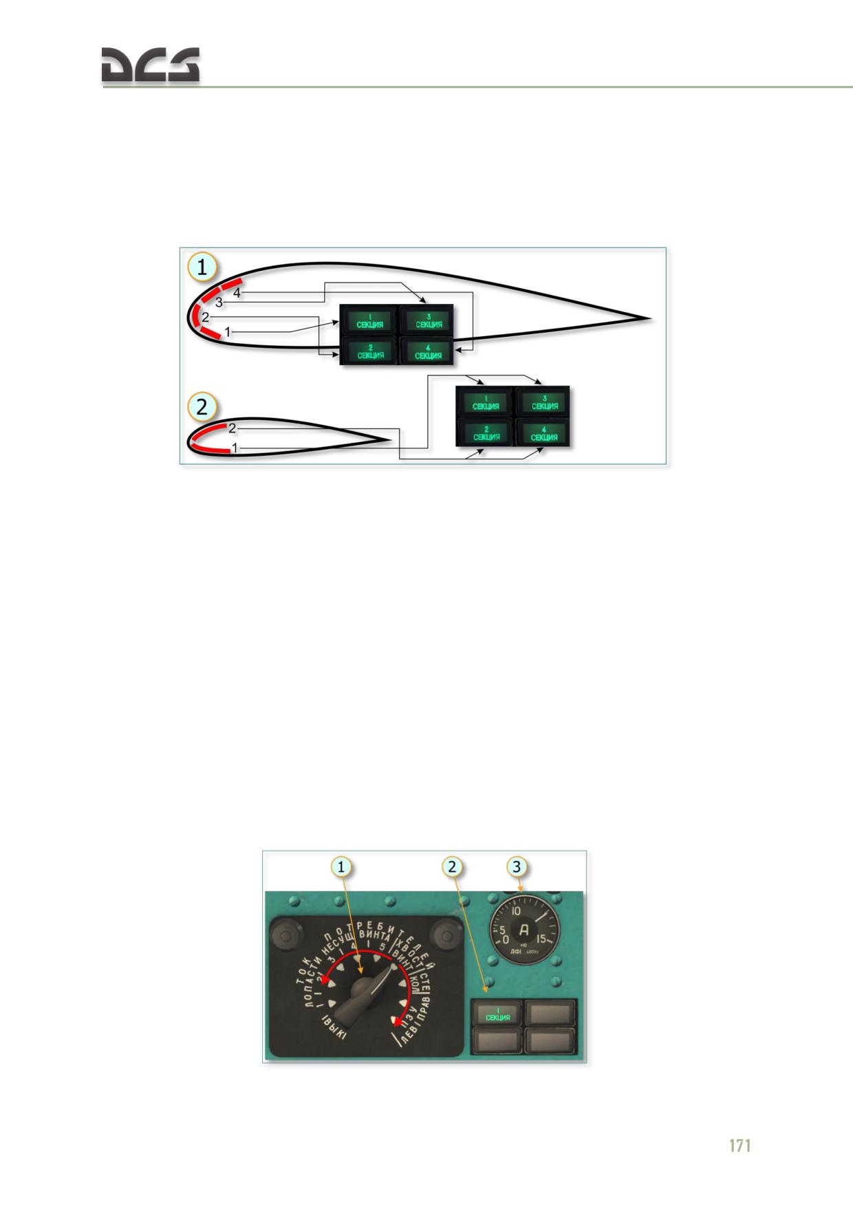
7.4.4. Rotors Anti-Ice System
Blades of main and tail rotors are heated by heating elements powered by AC
voltage.
Main rotor heating element comprises four sections, that of tail rotor is divided in two
sections.
Fig. 7.17. Main and Tail Rotors Blades Anti-Ice System. Diagram of Heating Elements
Location Relative to Blade Profile
1. Diagram of Main Rotor Heating Elements
2. Diagram of Tail Rotor Heating Elements
(4 sections)
(2 sections)
Sections are energized in cycles by cyclic timer ПМК-21. In one cycle, the cyclic timer
activates heating of every section of main and tail rotors for 38.5 sec and cooling of
them for 115.5 sec (main rotor section) and 38.5 sec (tail rotor section). Tail rotor
heating elements sections are energized in the following sequence: the first sections
of tail rotor blades’ heating elements are energized along with the sections I and III
of main rotor blades’ heating elements; the second sections are energized along with
the sections II and IV of main rotor blades’ heating elements.
For check of current value in every section of every main rotor blade and in tail rotor
sections, set rotary switch ТОКИ ПОТРЕБИТЕЛЕЙ (CONSUMERS CURRENTS) to
positions ЛОПАСТИ НЕСУЩ. ВИНТА (MAIN ROTOR BLADES) 1-2-3-4-5 and ХВОСТ
ВИНТА (TAIL ROTOR) in series when lamp of appropriate section comes on and
check current in relevant sections of blades by dashboard amperemeter, Fig. 7.18.
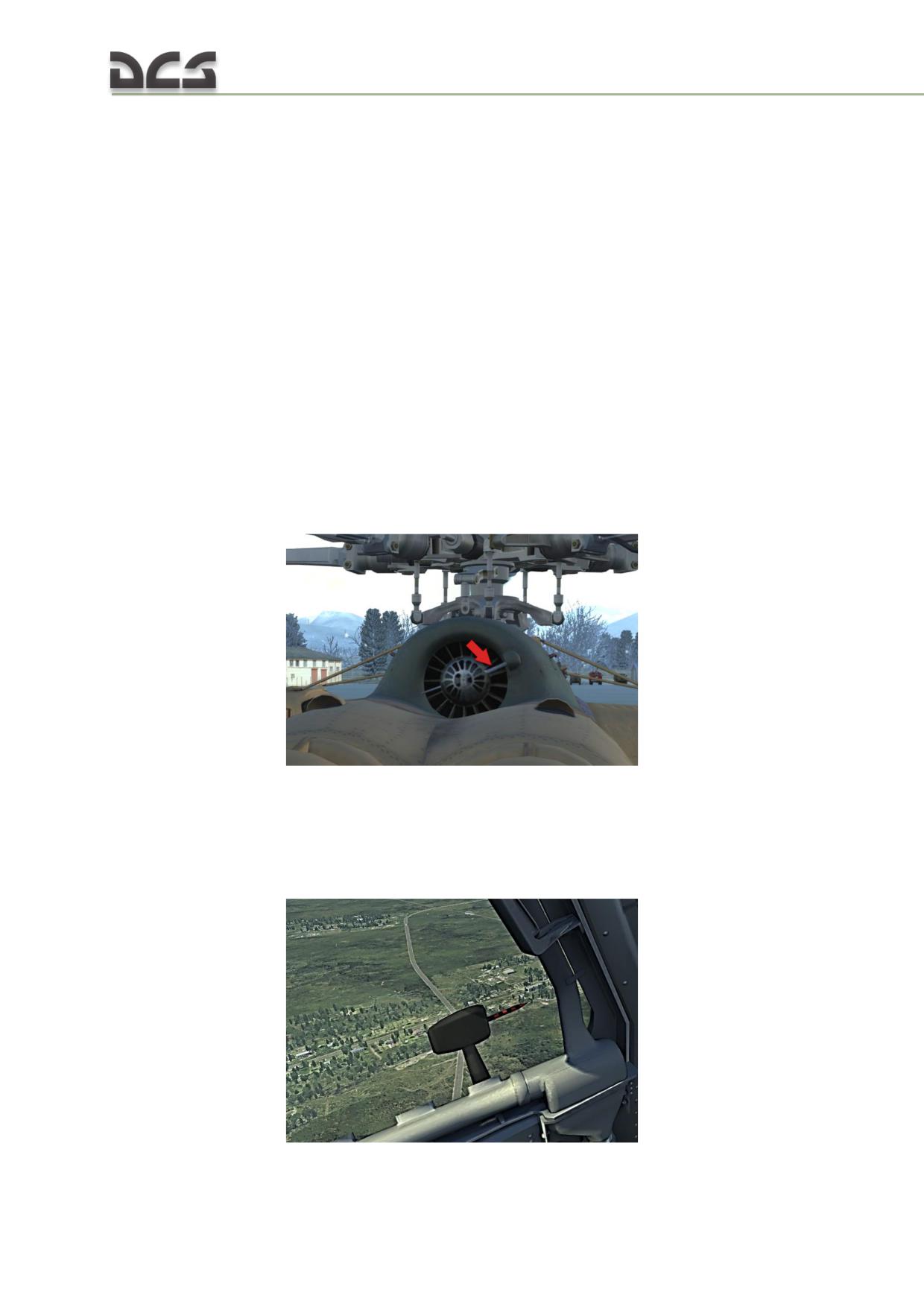
Fig. 7.18. Check of Anti-Ice System Heating Elements Electric Circuits Operation
1. Current consumers rotary switch
2. Lamp indicating energizing of separate
sections of main rotor and tail rotor
3. AC amperemeter
Dashboard amperemeter should be within:
60-72 A for main rotor blade;
110-150 A for tail rotor blades.
To know true value of current, amperemeter readings are to be divided by 3 for main
rotor blade and by 6 for tail rotor blades.
7.4.5. Ice Detectors
For timely detection of icing, warning about helicopter structures icing and automatic
energizing of anti-icing system, helicopter is equipped with radioisotopic ice detector
РИО-3 (RIO-3). Detecting unit of ice detector РИО-3 is installed in fan air intake
duct. Operation is based on variation in conductivity of electric circuit section, which
is energized by radioisotope beta-ray emission.
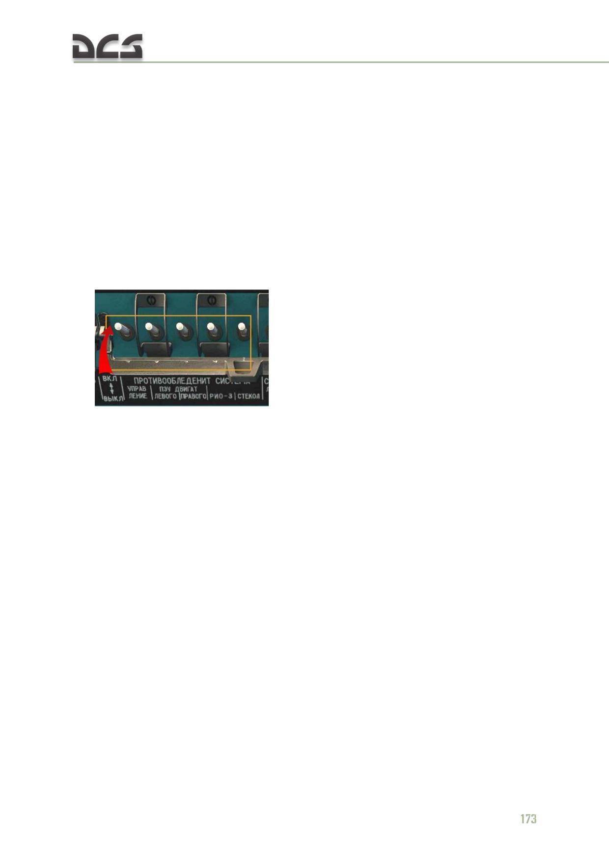
Fig. 7.19. Radioisotopic Ice Detector
Moreover, visual ice detector is fitted outside, on left land blister. Visual ice detector
is a rod on the left sliding blister. The rod has red and black vertical stripes, 5 mm
wide each. Pilot may use the rod to evaluate rate of icing (not implemented in the
stimulator).
Fig. 7.20. Visual Ice Detector
172
Radioisotopic ice detector serves for sending signal about initiation of icing to the
crew (continuous warning signal when helicopter is in icing zone) and automatic
energizing of anti-icing system (of both rotors, right engine and glasses). After
helicopter leaves icing zone, ice detector РИО-3 stops generation of signal; ant-icing
system is to be de-energized manually.
Signal from ice detector РИО-3 may be generated with certain delay if significant
amount of ice is already accumulated on PSS and engine units. After heating is
energized, accumulated ice may come off and get into engines, thus causing failure
of engines.
To avoid this, heating of PSS and engines is to be energized manually before flight.
7.4.6. Control of Anti-Ice System
1. For anti-ice system functioning in manual and automatic modes, anti-ice system
CB
should be on.
2. The control of anti-ice system is carried out using the anti-ice system Control
Panel, Fig. 7.21
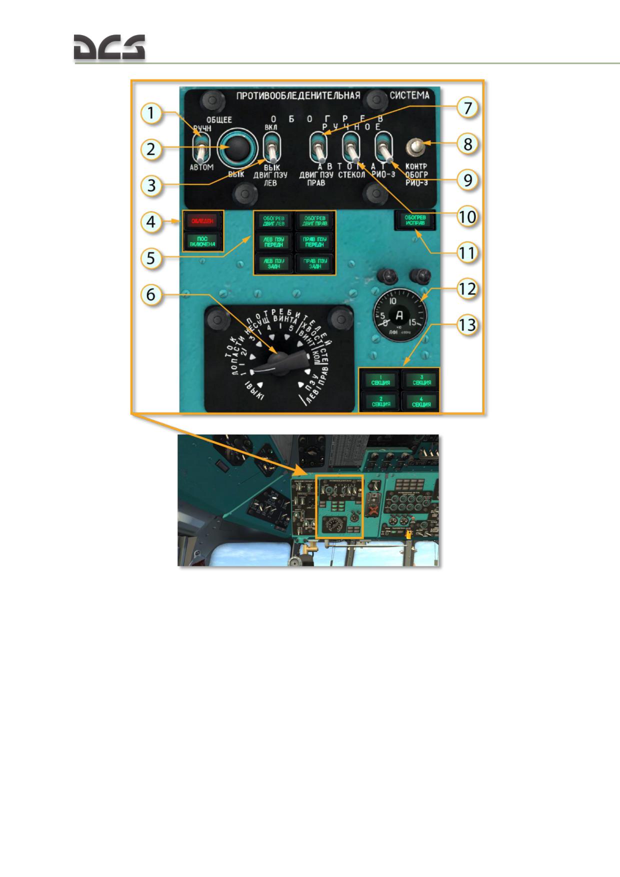
Fig. 7.21. Anti-Ice System Control Panel
1. Switch ОБЩЕЕ РУЧН-АВТОМ (GENERAL
7. Switch (manual - automatic activation)
MANUAL-AUTO)
ДВИГ ПЗУ ПРАВ (ENG PSS RIGHT) for PSS
2. Anti-ice system disabling button
and right engine inlet heating
3. Switch ДВИГ ПЗУ ЛЕВ (ENG PSS LEFT) for
8. Monitoring of detector РИО-3 heating
PSS and left engine inlet heating
9. Switch of detector РИО-3 heating
4. Icing indicator lamp (red) and anti-ice
10. Glasses heating switch
system activation indicator lamp (green)
11. Detector РИО-3 heating serviceability
5. Indicator lamp of PSS and left (left side)
indicator lamp
and right (right side) engines’ inlets heating
12. AC amperemeter
activated
13. Lamp indicating successive activation of
6. Rotary switch, for consumers current
main and tail rotors’ separate sections
monitoring
174
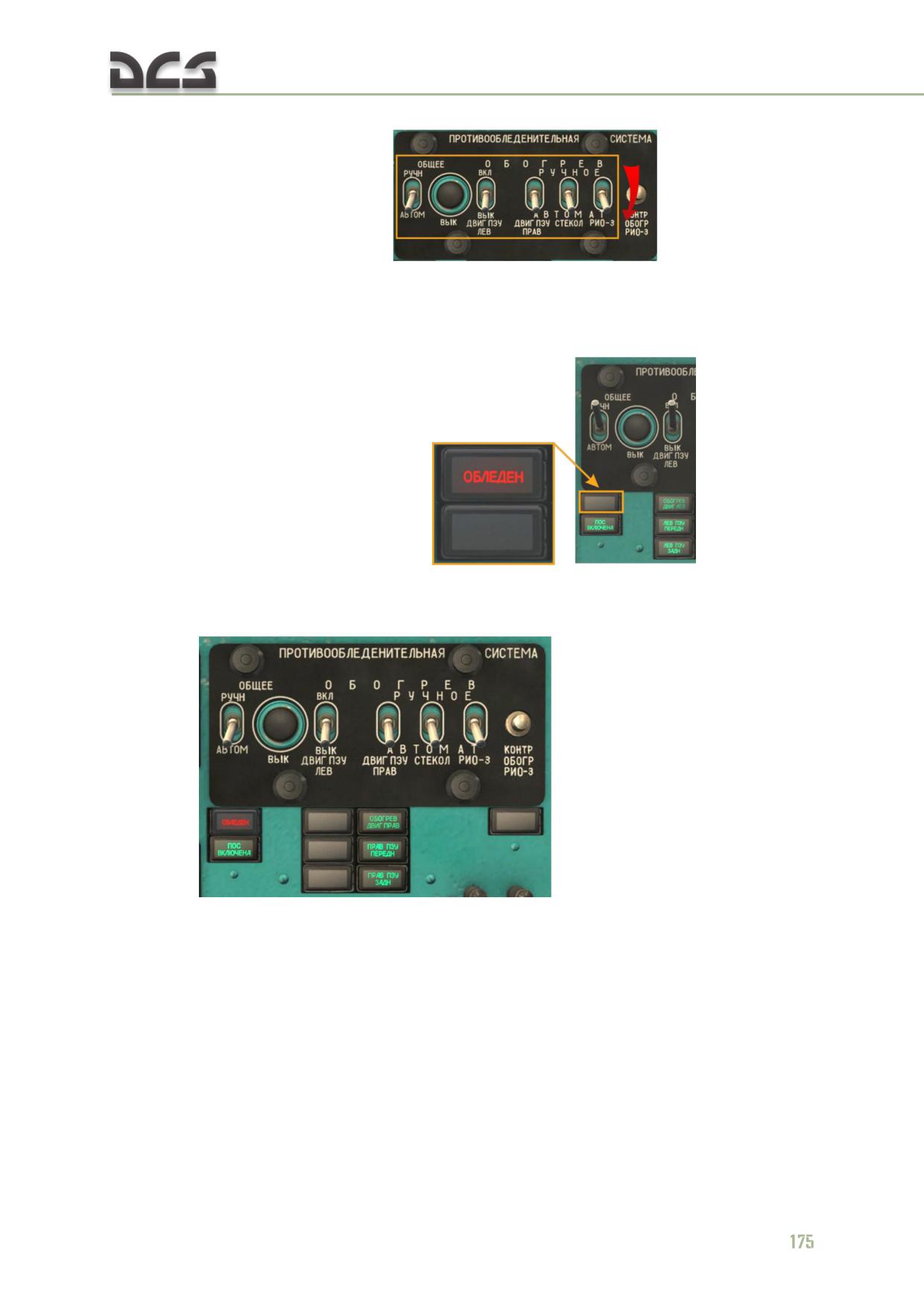
3. For anti-icing system operation in automatic mode, all switches on the control
panel should be in lower position:
Operation in automatic mode is based on receiving a signal from ice detector РИО-3
by anti-ice system control unit. At that, under icing conditions, anti-ice system and
warning system generates the following signals:
for ОБЛЕДЕН (ICING) lamp
coming on;
for automatic energizing of anti-icing system of rotors blades, right
engine, its air intake, PSS and glass heating - the same may be verified
by appropriate lamps coming on
;
for replay of РИ-65 (RI-65) voice recorder message: ОБЛЕДЕНЕНИЕ
(ICING);
to the САРПП-12ДМ (SARPP-12DM) flight data recorder, for producing
signal ОБЛЕДЕН (ICING).
If anti-ice system was energized automatically, energize anti-ice system of PSS and
LEFT engine inlet manually (set switch ДВИГ ПЗУ ЛЕВ (LEFT ENG PSS) to top
position), after you make sure in stable operation of right engine.
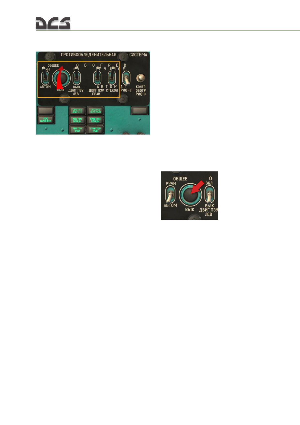
4. For anti-icing system operation in manual mode, all switches on the control
panel
should
be
in
upper
position
(exept
РИО-3
swith):
Moreover, manual energizing of anti-ice system for separate units is possible: main
rotor and tail rotor; left engine (PSS and engine inlet); right engine (PSS and engine
inlet); glasses.
5. To de-energize anti-ice system, set all anti-ice system switches to off (down) on
the control panel and press button ВЫК (OFF)
7.4.7. The effect of Anti-Ice System system on the flight characteristics
Maximum takeoff weight
With PZU (PSS) turned on, reduce maximum takeoff weight indicated in charts Fig.
8.1 , Fig. 8.2Fig. 8.3 by 200 kg. With engine and rotor anti-ice systems turned on,
reduce maximum takeoff weight indicated in this charts by 1000 kg.
Fuel consumption
With anti-ice system engaged, fuel consumption rates indicated in the tables Table
8.4 increase as follows:
engine anti-ice system: 3%
main and tail rotor anti-ice system: 2%
With the PZU (PSS) engaged, fuel consumption rates per hour provided in Table 8.4
increase by 3%.
7.5. Pneumatic System
Helicopter pneumatic system serves for breaking of main landing gear wheels and
charging of wheels tubes from on-board bottles when helicopter is not on an airfield
(Fig. 7.22).
176
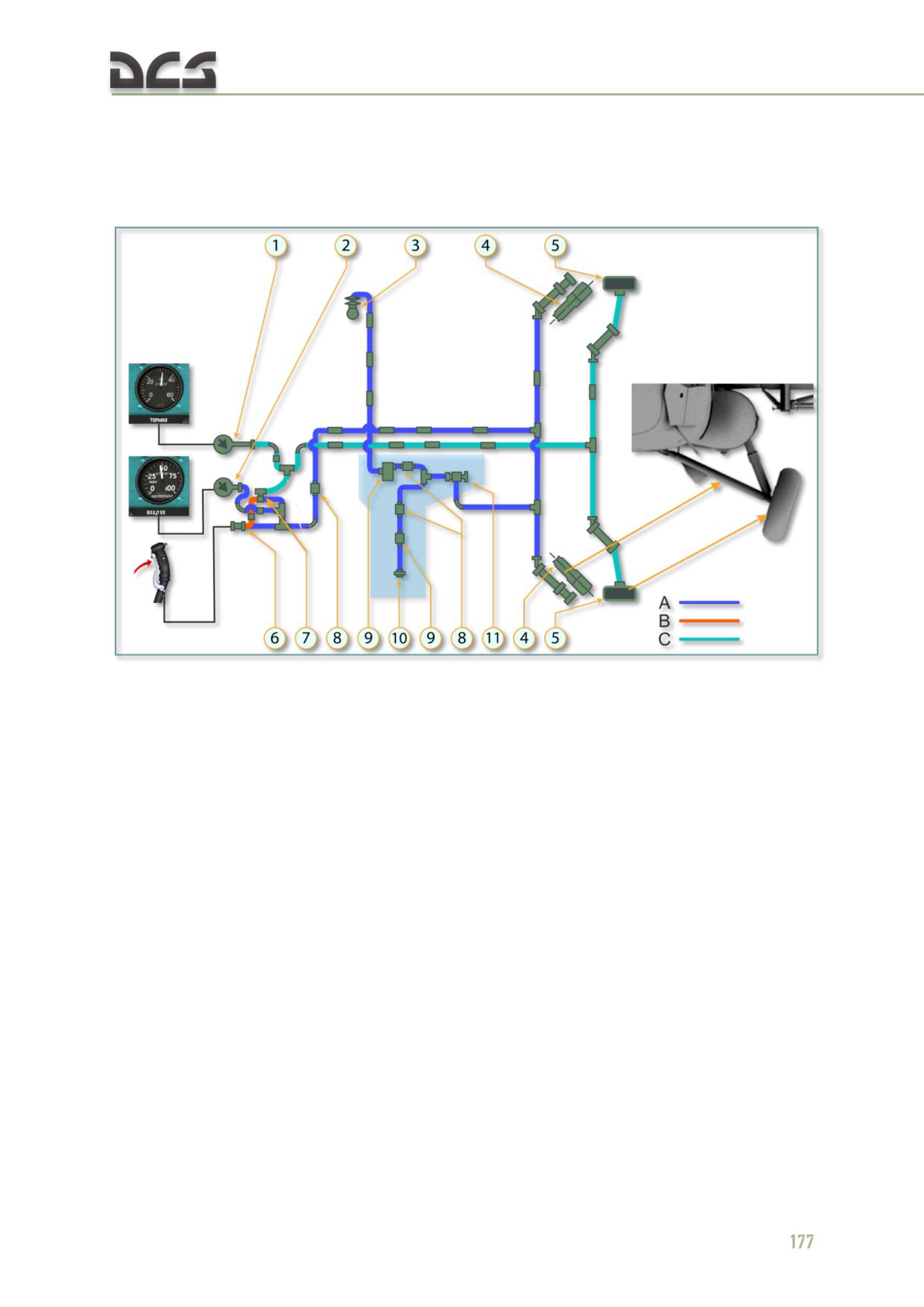
Compressed air under pressure 50 kgf/cm² is stored in bottles enclosed in main
landing gears brace struts.
Bottles are charged from compressor driven from main gear when engine is running,
or from ground bottle via charging connection.
Fig. 7.22. Pneumatic System Diagram
1. Pressure gauge МА-60К
8. Check valve 636100М
2. Pressure gauge НТМ-60
9. Filter
3. Compressor АК-50Т,
9. Filter
4. Bottles
10. Charging valve 3509c50
5. Wheel break
11. Pressure control unit АД-50
6. Reducing valve УП-25/2
A - pressure 40..54 kgf/cm²
7. Reducing accelerator УПО3/2М
B - pressure 0..14 kgf/cm²
C - pressure 30..34 kgf/cm²
(1) PRESSURE GAUGE МА-60К serves for breaks pressure monitoring;
(2) PRESSURE GAUGE НТМ-60 serves for bottles pressure monitoring (4);
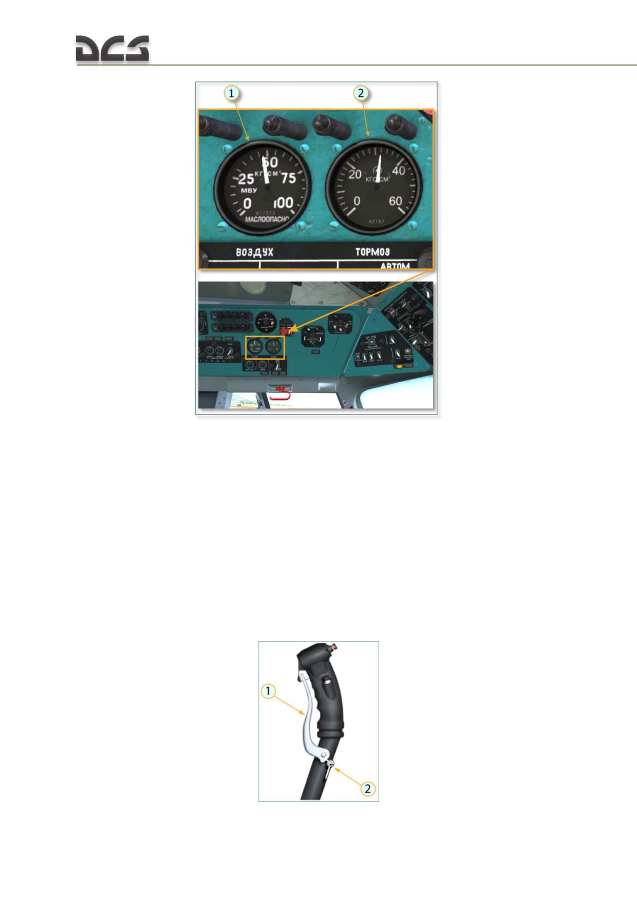
Fig. 7.23. Pressure gauges of Pneumatic System
1. Pressure gauge НТМ-60 (NTM-60)
2. Pressure gauge МА-60К (MA-60K)
(3) AIR COMPRESSOR АК-50Т (AK-50T) serves for re-charging of helicopter pneumatic
system with compressed air during flight. Compressor provides for charging of on-
board bottles with air to pressure (5000+400) kPa [(50+4) kgf/cm²] within no more
than 25 min. Air compressor АК-50Т is driven from main gear.
(4) BOTTLES. Bottles are formed by internal cavities of main landing gears brace
struts.
(5) WHEEL BRAKE is of drum type; for breaking, air presses pads to the drum.
(6) REDUCING VALVE УП25/2 (UP25/2) controls breaks of main landing gears’ wheels
pneumatically. Control is effected by lever on cyclic pitch control stick, Fig. 7.24.
178
Fig. 7.24. Wheel Break Lever on Left Cyclic Pitch Control Stick
1. Breaks control lever
[W]
2. Parking break trigger
[LShift +W]
(7) REDUCING ACCELERATOR УПО3/2М (UPO3/2M) accelerates compressed air feed to
main gears wheels breaks; also, it ensures air bleed to atmosphere during breaks
release. Reducing accelerator operates from pilot pressure fed from reducing valve
УП25/2; the accelerator creates pressure of (3300+300) kPa [(33+3) kgf/cm²] in
break line.
(11) PRESSURE CONTROL UNIT АД-50 (AD-50) switches over modes of АК-50Т
compressor operation (operating mode to idle mode and vice versa), automatically.
Compressor is switched from operating to idle mode under air bottles pressure
(5000+400) kPa [(50+4) kgf/cm²], and from idle to operating mode under pressure
not less than 4000 kPa (40 kgf/cm²). Pressure control unit is installed on the
pneumatic units’ panel.
NOTE. Pneumatic units’ panel facilitates units installation and tightness check; also, it allows to reduce
number of pipes. It accommodates some pneumatic system units. The panel is located in fuselage
cargo compartment, left side.
Primary technical details of pneumatic system:
Parameter Description
Minimum
Nominal Value
Maximum
Value
Value
Bottles air pressure, kgf/cm²
40
50
54
Wheel breaks air pressure, kgf/cm²
30
32
34
Normal Operation
Check charging of air system (system pressure read by pressure gauge ВОЗДУХ
(AIR) should be 40...50 kg/cm²) and operation of landing gear wheels break system
(when break lever is pressed, wheel breaks pressure read by pressure gauge
ТОРМОЗ (BREAK) should be 30...34 kgf/cm²; after brake release, no residual
pressure in breaks is allowed).
7.6. Fire Protection System
7.6.1. Brief Description
Fire protection equipment serves for fire detection, indication and extinguishing in
the protected units. The helicopter fire protection equipment comprises fire detection
and alarm system and fire extinguishing system that includes two ballons with fire-
extinguishing liquid (one ballon is the first order operation; another is the second
order operation). After СИГНАЛИЗАЦИЯ (INDICATION), 1 ОЧЕРЕДЬ (THE FIRST
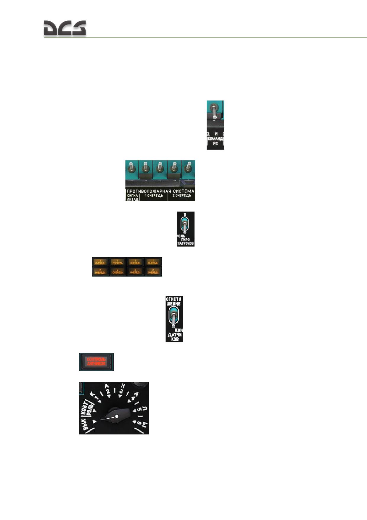
ORDER), 2 ОЧЕРЕДЬ (THE SECOND ORDER) breakers are switched on, electric
circuit is powered by battery bus, Fig. 7.25:
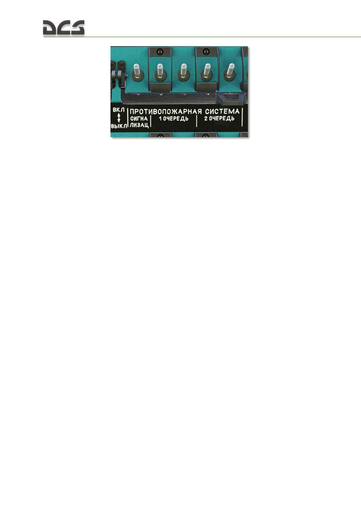
Fig. 7.25. Fire Protection System circuit breakers
7.6.2. Fire detection and alarm system
ССП-ФК (SSP-FK) fire indication system serves for fire indication and crew warning.
The ССП-ФК (SSP-FK) fire indication system serves for:
fire indication in the helicopter protected units
crew warning by light alarm
producing for additional signals on the voice data and flight variables
auto-recording equipment
automatic energizing of the first order ballon discharging in the unit where
fire signal was detected
indication of fire-extinguishing equipment operation
monitoring of system serviceability and alertness.
The ССП-ФК (SSP-FK) equipment operation is based on receiving and processing electrical signal from
the special detecting units. This unit is a thermopile. It assembles of three alternately connected
chromel-alumel thermocouples. Electrodes hot junctions (fast-response) are much lesser size than
non-operating (slow-response) ones. When the unit enviroment heating fast, its fast-response
junctions heat much faster than slow-response ones as fast-response junctions are lesser mass. Due
to the difference of hot and non-operating junctions heating temperatures, thermal electromotive
force appears on the unit output rod.
Fire detection system
There is three sets of the ССП-ФК (SSP-FK) equipment on the helicopter. They
serves for fire detection in four units that are more dangerous in relation of fire
hazard. These units are as follows:
the left engine
the right engine
КО-50 kerosene-combustion heater
the main rotor transmission, the fuel consumed tank and the АИ-9В (AI-
9V) engine (these three sections are included into one protected unit).
Fire detection system operates on a multiple-circuit electric device. It is equipped with some
standalone sensor groups, which initiate signals on actuation devices, in each monitored unit.
In the actuating unit, each sensor group is connected to its signal conditioner (combined unit) forming
a fully independent sensitive circuit. Thereby, it is ensured high system reliability, as in case of any
180
sensor group failure, normal operation of the other sensor groups stays constant. The system is able
to detect a fire by one circuit of sensitive elements.
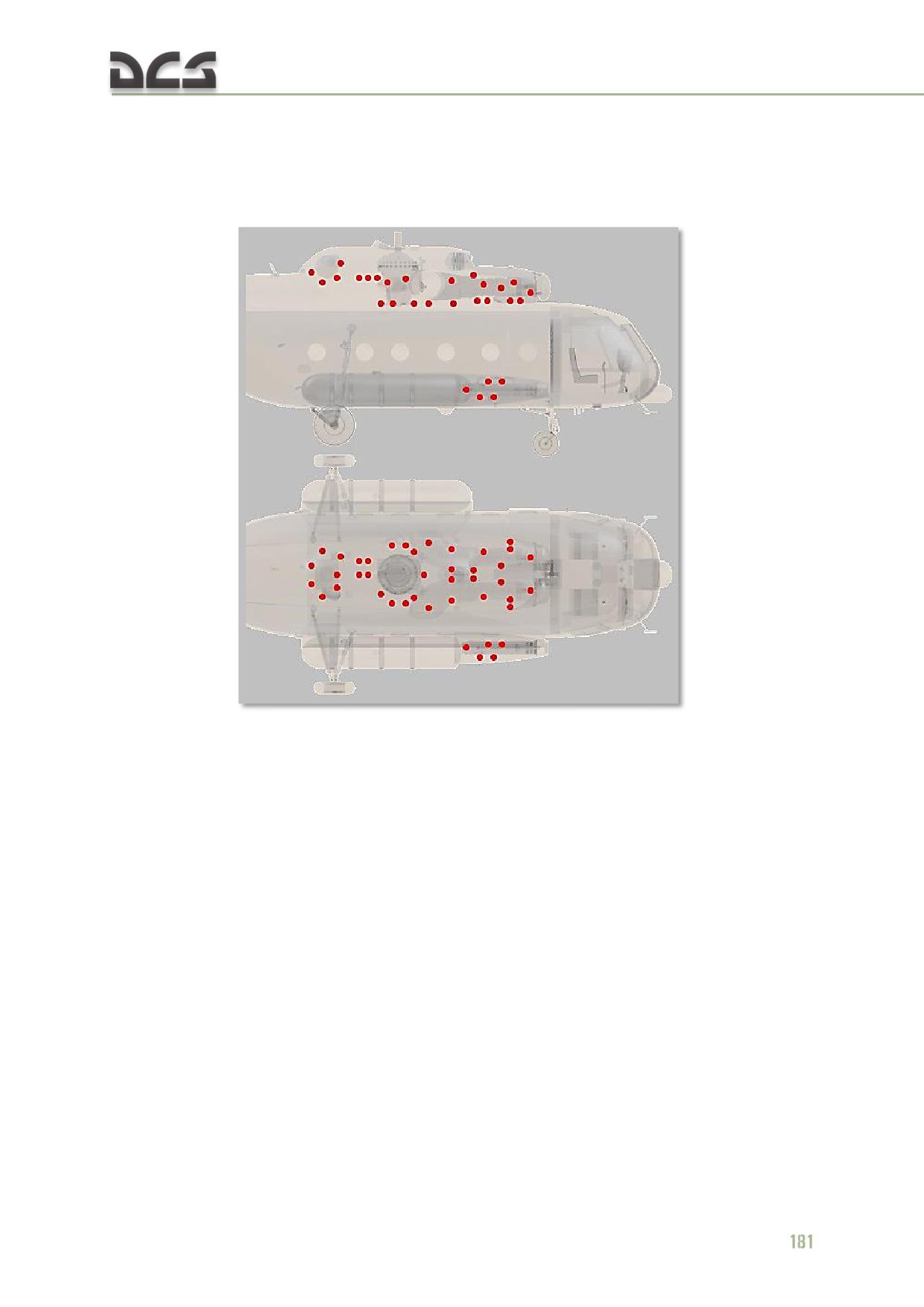
The ССП-ФК (SSP-FK) system comprises the following:
42 FAS (fire-alarm sensor) signal devices type integrated into 14 groups.
Fig. 7.26. Location of the ССП-ФК (SSP-FK) system sensors
three ССП-ФК-БИ (SSP-FK-BI) actuating units, which receive electric
signals initiating in sensors circuit in event of fire and control indication
system and automatic equipment. The actuating units are installed in the
cockpit on the right rack.
Fire alarm system
Light alarm. Fire light alarm system comprises five indicating lamps with red filters
installed on the fire protection system switchboard, Fig. 7.27, 1:
Two ПОЖАР ЛЕВ. ДВ. (LEFT ENGINE FIRE) and ПОЖАР ПРАВ. ДВ.
(RIGHT ENGINE FIRE) lamps indicate about a fire in the helicopter left
and right engine units
ПОЖАР КО-50 (КО-50 FIRE) lamp indicates about a fire in the КО-50
kerosene-combustion heater unit
ПОЖАР РЕДУК. АИ-9 (ROTOR TRANSMISSION FIRE АI-9) lamp indicates
about a fire in the units of the main rotor transmission, the fuel consumed
tank and the АИ-9В (AI-9V) engine
ПОЖАР (FIRE) lamp is an additional lamp on the left dashboard which
duplicates any of four main lamps coming on, Fig. 7.28.
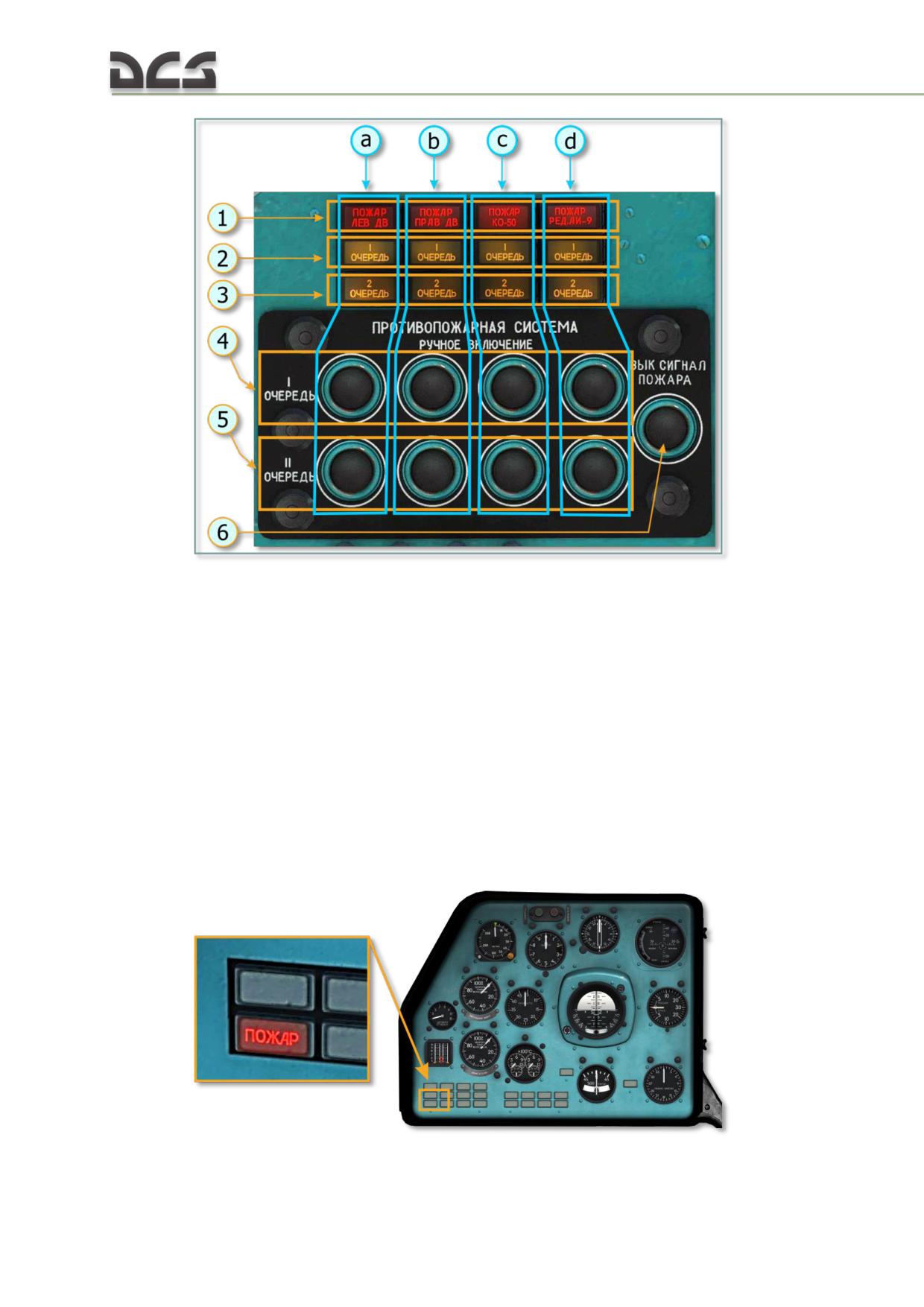
Fig. 7.27. Fire protection system switchboard on Center overhead console
1. The lamp indicating fire in the protected
Letters mark lamps indicating fire, operation of
units (ПОЖАР ЛЕВ ДВ, ПОЖАР ПРАВ ДВ
fire extinguishing system ballons and push
ПОЖАР КО-50, ПОЖАР РЕД.АИ-9) (LEFT
buttons of units fire protection system as
ENGINE FIRE, RIGHT ENGINE FIRE, КО-50
follows:
FIRE, MAIN ROTOR АИ-9 FIRE)
a. The LEFT engine
2. The lamp indicating operation of the first
b. The RIGHT engine
order fire extinguishing system
c. The КО-50 kerosene-combustion heater
3. The lamp indicating operation of the second
d. The main rotor transmission, the fuel
order fire extinguishing system
consumed tank and APU
4. The first order fire extinguishing system
push button
5. The second order fire extinguishing system
push button
6. Alarm silence push button
Fig. 7.28. Lamp ПОЖАР (FIRE) on the left dashboard
182
To capture the crew attention to fire alert in any unit as soon as possible, it is
provided for operation these five indication lamps in flashing mode. For this purpose,
its supply circuits are connected into the helicopter FLASHER (МИГАЛКА) system
scheme.
Auxiliary alarm signal. Simultaneously with energizing the lamp, fire protection
system serves for sending auxiliary alarm signals by parallel circuit in the unit input in
the РИ-65 (RI-65) voice data equipment kit. Depending on the site of the fire, a
signal comes on one of the four channels, which herewith energizing and serves for
replay of the РИ-65 (RI-65) voice recorder message to the left pilot’s phones:
ПОЖАР ЛЕВЫЙ ДВИГАТЕЛЬ, ПОЖАР ПРАВЫЙ ДВИГАТЕЛЬ, ПОЖАР РЕДУКТОР
ВСУ, ПОЖАР КО-50 (LEFT ENGINE FIRE, RIGHT ENGINE FIRE, ROTOR
TRANSMISSION APS FIRE, КО-50 FIRE).
The voice recorder message comes to the left pilot’s phones repeatedly and replays
on a periodic basis of two messages per 12 s. Simultaneously, the same message is
sent to the flight ground control station and the unit input in the flight variables
auto-recording equipment (САРПП-12ДМ (SARPP-12DM)) via the helicopter
command communication VHF radio.
7.6.3. Indication and alarm system check
Indication and alarm system serviceability are monitored by checking of the
indicating lamps and monitoring of the sensors serviceability.
LAMPS SERVICEABILITY and its power supply circuits are checked by the helicopter lamps
check system with the ПРОВЕРКА ЛАМП. МИГАЛКА (LAMP CHECK. FLASHER) circuit
breaker and the МИГАЛКА (FLASHER) switch set to on.
When setting the ПРОВЕРКА МИГАЛКИ-СИГНАЛ. ЛАМП switch on the pilot’s central
console to the ПРОВЕРКА МИГАЛКИ (FLASHER CHECK) position, five fire indication
lamps should come on in flashing mode (Fig. 7.27, 1 и Fig. 7.28). When setting the
ПРОВЕРКА СИГНАЛ. ЛАМП switch on, eight 1 ОЧЕРЕДЬ (1 ORDER) and 2 ОЧЕРЕДЬ
(2 ORDER) lamps should come on (Fig. 7.27, 2, 3).
FAS SIGNAL DEVICES SERVICEABILITY and its power supply circuits are monitored by the
КОНТРОЛЬ ДАТЧИКОВ (MONITORING OF SIGNAL DEVICES) panel (Fig. 7.29) on
the mid section of electric panel after the ОГНЕТУШЕНИЕ-КОНТРОЛЬ ДАТЧИКОВ
(FIRE EXTINGUISHING - MONITORING OF SIGNAL DEVICES) switch set to the
КОНТРОЛЬ ДАТЧИКОВ (MONITORING OF SIGNAL DEVICES) position. Herewith,
КОНТРОЛЬ ДАТЧИКОВ (MONITORING OF SIGNAL DEVICES) red indicator lamp (Fig.
7.29, 3) comes on, indicating monitoring circuit readiness
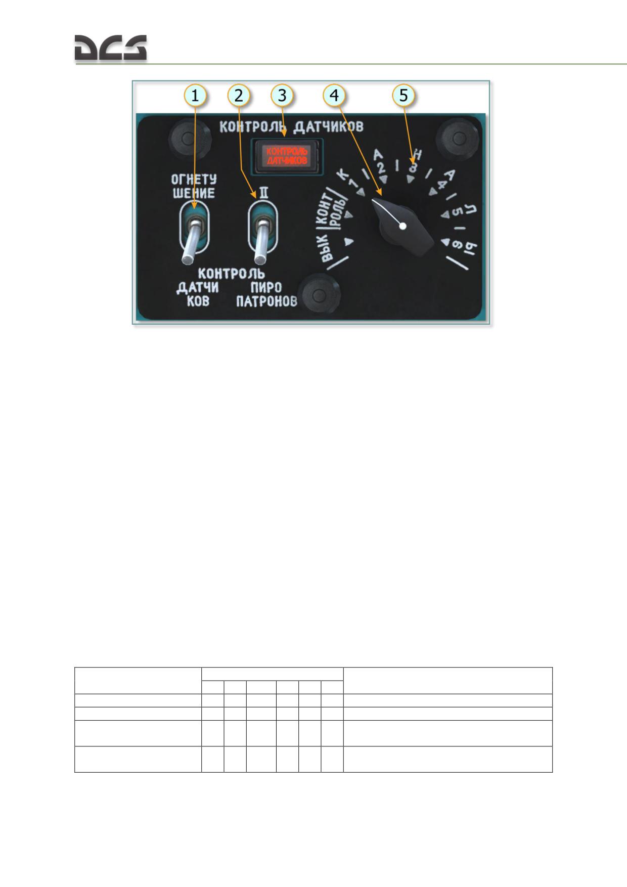
Fig. 7.29. КОНТРОЛЬ ДАТЧИКОВ (MONITORING OF SIGNAL DEVICES)
Center overhead console
1. ОГНЕТУШЕНИЕ - КОНТРОЛЬ ДАТЧИКОВ
4. ВЫК - КОНТРОЛЬ - КАНАЛЫ (OFF -
(FIRE EXTINGUISHING - MONITORING OF
MONITORING - CHANNELS)1-2-3-4-5-6
SIGNAL DEVICES) switch
switch
2. Switch I - II checking of pyros on fire-
5. Positions for connection of signal devices
extinguishing liquid ballons
channels 1-2-3-4-5-6 or monitoring shutting
3. Lamp indicating position of switch (1)
down (ВЫК (OFF))
КОНТРОЛЬ ДАТЧИКОВ (MONITORING OF
SIGNAL DEVICES)
Monitoring system is operated by battery bus via ПРОТИВОПОЖАРНАЯ СИСТЕМА.
СИГНАЛИЗАЦ. (FIRE PROTECTION SYSTEM. INDICATION) circuit breaker and
КОНТРОЛЬ ДАТЧИКОВ (MONITORING OF SIGNAL DEVICES) rotary switch. Fourteen
groups of FAS signal devices are integrated into six monitoring channels (Fig. 7.29,
4). Each of them connected to its switch contact. For monitoring, each switch is
required to set to checking channels position alternately. In case of serviceability of
signal devices in the groups and its power supply circuits, on the mid section of the
electric panel and the left dashboard, appropriate lamps, indicating fire, should come
on (Fig. 7.27, 1 и Fig. 7.28).
Division of the groups of the different units signal devices for monitoring channels is
given in the table:
Monitored units
Monitoring channels
Lamps come on
I
II
III
IV
V
VI
Left engine
+
+
+
ПОЖАР ЛЕВ. ДВ. (LEFT ENGINE FIRE)
Right engine
+
+
+
ПОЖАР ПРАВ ДВ. (RIGHT ENGINE FIRE)
Main rotor transmission,
+
+
+
+
ПОЖАР РЕДУК. АИ-9 (MAIN ROTOR АИ-9
Service fuel cell
(AI-9) FIRE)
АИ-9В (AI-9V) engine
+
+
ПОЖАР РЕДУК. АИ-9 (MAIN ROTOR АИ-9
(AI-9) FIRE)
184
КО-50 Kerosene-
+
+
ПОЖАР КО-50 (КО-50 FIRE)
combustion heater
7.6.4. Fire extinguishing system
Fixed fire extinguishing system comprises two УБШ-4-4 (UBSH-4-4) type ball shaped
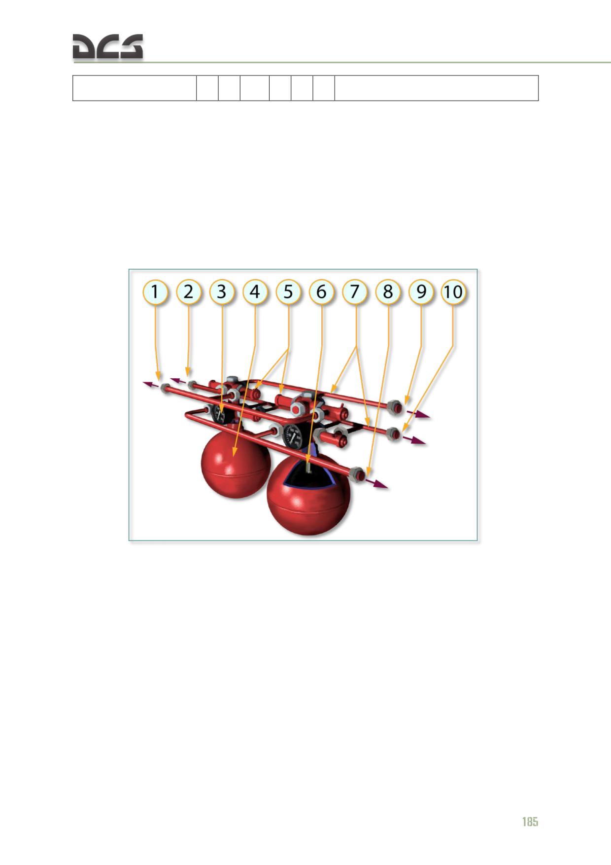
ballons with extinguishing agent served for two orders discharging, Fig. 7.30. The
ballon is charged extinguishing agent comprised of Freon gas 114В2 weighing
5,640 kg and, for providing this agent supply, it is charged air mixture or nitrogen
weighing 0,180 kg to the pressure (10500...11500) kРа [(105...115) kgf/cm2] at a
temperature of 15...20 °С. Each ballon is equipped with four initiators (as per the
number of protected units). Each initiator is opened by two pyros. Ballons are located
in the unit of the main rotor transmission on the starboard side.
Fig. 7.30. УБШ-4-4 (UBSH-4-4) Fire extinguisher
1. Branch pipe to the unit of main rotor
5. ПГКц (PGKts) Initiator
transmission, the fuel consumed tank and АИ-
6. Siphon tube
9В (AI-9V) engine
7. Collector component
2. Branch pipe outboard
8. Branch pipe to the КО-50 unit
3. Pressure gauge
9. Branch pipe to the left engine unit
4. УБШ-4-4 (UBSH-4-4) Fire extinfuisher
10. Branch pipe to the right engine unit
ballon, collector component
Please note, that during fire extinguishing in the unit of the main rotor transmission,
the fuel consumed tank and the АИ-9В (AI-9V) engine, extinguishing agent spreads
through three protected sections (the section of the main rotor transmission, the
section of the fuel consumed tank as well as the section of the АИ-9В (AI-9V)
engine), in spite of there was a fire in the section of the fuel consumed tank (for
example).
7.6.5. Normal Operation
Operating Conditions (stages) and required actions
1. CHECK OF SERVICEABILITY OF ELECTRICAL POWER SYSTEM FIRE PROTECTION EQUIPMENT.
After energizing the electrical power sources, it is required to:
set the РАДИО (RADIO) breaker to off
;
set the ПРОТИВОПОЖАРНАЯ СИСТЕМА (FIRE PROTECTION SYSTEM)
breaker to on
;
set the КОНТРОЛЬ ПИРОПАТРОНОВ (PYROS MONITORING) switch to the
positions I and II alternately
, make sure that pyros electric circuits
are serviceable (no yellow fire extinguisher indicator lamps should come
on)
;
set the КОНТРОЛЬ ДАТЧИКОВ-ОГНЕТУШЕНИЕ (MONITORING OF
SIGNAL DEVICES - FIRE EXTINGUISHING) switch to the КОНТРОЛЬ
(MONITORING) position
. At that, the КОНТРОЛЬ ДАТЧИКОВ
(MONITORING OF SIGNAL DEVICES) indicator lamp should come on
;
set the rotary switch to positions of six channels alternately
When setting the switch to positions 1 and 2, the following lamps should come on:
ПОЖАР ЛЕВ. ДВ. (LEFT ENGINE FIRE), ПОЖАР ПРАВ.ДВ. (RIGHT ENGINE FIRE),
ПОЖАР КО-50 (КО-50 FIRE), ПОЖАР РЕДУК.АИ-9 (ROTOR TRANSMISSION АИ-9
186
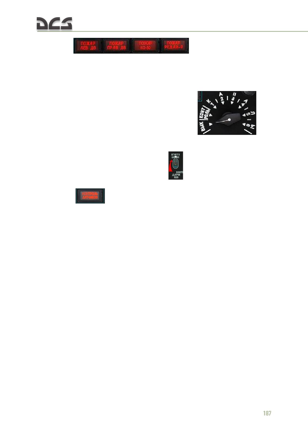
(AI-9) FIRE)
. When setting the switch to
the position 3, the КО-50 fire indicator lamp should go off. When setting the switch
to the positions 4, 5 and 6, the ПОЖАР РЕДУК.АИ-9 (ROTOR TRANSMISSION АИ-9
(AI-9) FIRE) indicator lamp should come on, ahother lamps should go off.
2. SYSTEM PREPARATION FOR WORK
set the rotary switch to the ВЫК (OFF) position
;
set the КОНТРОЛЬ ДАТЧИКОВ-ОГНЕТУШЕНИЕ (MONITORING OF
SIGNAL DEVICES - FIRE EXTINGUISHING) switch to the ОГНЕТУШЕНИЕ
(FIRE EXTINGUISHING) position
. At that, the КОНТРОЛЬ
ДАТЧИКОВ (MONITORING OF SIGNAL DEVICES) indicator lamp should go
off
The system is ready to automatic operation or manual actuation.
3. SWITCHING THE SYSTEM OFF
After taxiing in and shutting down the engines, for switching the system off, set the
ПРОТИВОПОЖАРНАЯ СИСТЕМА (FIRE PROTECTION SYSTEM) breaker to off.
WARNING. To avoid operating of the first (automatic) order fire extinguishers of
the system, do not set the rotor switch from the ВЫКЛ (OFF) position if the
КОНТРОЛЬ ДАТЧИКОВ-ОГНЕТУШЕНИЕ (MONITORING OF SIGNAL DEVICES - FIRE
EXTINGUISHING ) switch is in the position ОГНЕТУШЕНИЕ (FIRE EXTINGUISHING),
and do not set the КОНТРОЛЬ ДАТЧИКОВ-ОГНЕТУШЕНИЕ (MONITORING OF
SIGNAL DEVICES - FIRE EXTINGUISHING ) switch to the ОГНЕТУШЕНИЕ (FIRE
EXTINGUISHING) position before the rotor switch is set to the ВЫКЛ (OFF) position.
The system operation and crew procedure
with fire protection equipment in case of fire
If there is any protected units fire (for example, the left engine fire) and thermal
electromotive force on any signal devices channels, the following lamps come on:
the ПОЖАР ЛЕВ ДВ (LEFT ENGINE FIRE) lamp on the fire protection
system switchboard (Fig. 7.27, 1-a);
the ПОЖАР (FIRE) lamp on the left dashboard (Fig. 7.28).
Simultaneously, pyro of extinguishing liquid supply line of the first order ballon
detonates. At that, the 1 ОЧЕРЕДЬ (1 ORDER) indicator lamp of the first order
operation on the fire protection system switchboard comes on (Fig. 7.27, 2-a).
When fire is extinguished, during not more than 10 s, thermal electromotive force on
any signal devices channels disappeares and the ПОЖАР ЛЕВ ДВ (LEFT ENGINE
FIRE) lamp goes off, but the 1 ОЧЕРЕДЬ (1 ORDER) lamp continues to come on.
When the lamps do not go off in 10 s, press the ВЫК. СИГНАЛИЗАЦИИ ПОЖАРА
(ALARM SILENCE PUSH BUTTON) button (Fig. 7.27, 6).
When the first order ballon is not operated automatically, the ПОЖАР ЛЕВ ДВ (LEFT
ENGINE FIRE) lamp on the fire protection system switchboard and the ПОЖАР
(FIRE) lamp on the left dashboard come on, but the 1 ОЧЕРЕДЬ (1 ORDER) lamp
does not come on), it is required to detonate the pyro of extinguishing liquid supply
line to the left engine unit of the first order ballon manually by pressing the
1
ОЧЕРЕДЬ (1 ORDER) button for the left engine unit (Fig. 7.27, 4-a).
When the left engine fire is extinguished by the first order ballon, and then there is
another unit fire (for example, the unit of the main rotor transmission, the fuel
consumed tank and APS (auxiliary power supply)), that is required to detonate the
pyro of the second order ballon manually by pressing the 2 ОЧЕРЕДЬ (2 ORDER)
button for the unit of the main rotor transmission, the fuel consumed tank and APS
(Fig. 7.27, 5-d). After that, the 2 ОЧЕРЕДЬ (2 ORDER) lamp, located under the
ПОЖАР РЕД.АИ-9 (ROTOR TRANSMISSION АИ-9 FIRE) lamp on the fire protection
system switchboard, comes on (Fig. 7.27, 3-d).
NOTE. After fire extinguishing system operating in the unit of the main rotor transmission, the fuel
consumed tank and APS operates, the АИ-9В (AI-9V) engine shuts down, if it operates, and its start is
blocked. That is similar to the КО-50 unit.
See also Onboard fire
7.7. Environmental and heating system
7.7.1. Brief description
The environmental and heating system is used for creating and maintaining
comfortable environmental conditions for crew and passengers. It provides:
supply of heated and atmospheric air to the cockpit and cargo cabin;
airflow for blowing on front winshields and cockpit blisters.
This system consists of the KO-50 combustion heater and two DV-302T cockpit fans
for right and left pilot.
The heater is operating in the following way: after heater was started, in the
combustion camera the kerosene-air mixture is being burned and exhaust gas is
being removed through the exhaust nozzle. Heat from the combustion, is warming
up the calorifer. The airflow from a fan is moving through calorifer, air is being
warmed up and fed to the helicopter’s cockpit.
The heater can operate either in automatic, manual or ventilation mode. When
heater is operating in automatic mode, the temperature, set by the temperature
knob, is being maintained constant. Manual control is used for maximum or medium
heating output modes. The recirculation mode is used to speed up the heating of the
cabins during winter conditions, by using air from the cargo cabin. In the game, this
188
behavior of shut-dumper is not modelled. In the ventilation mode, this system
provides cooling of the heater and cabins ventilation (through air ducts) during
warmer seasons.
In the electrical circuit of the heater, the relay, which disconnects electrical power
supply in case of a fire in the KO-50 bay, is installed.
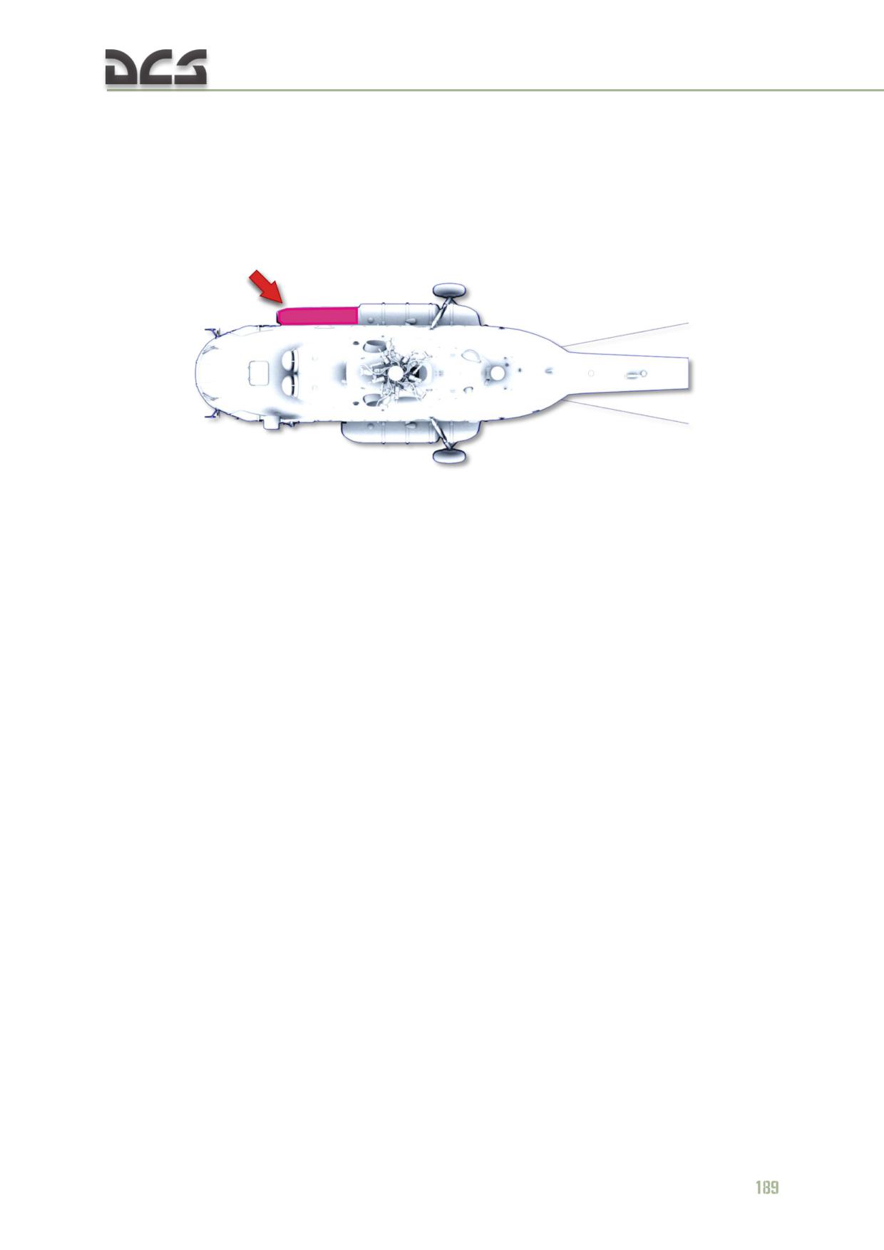
The KO-50 heater is located in front of the right external fuel tank, Fig. 7.31:
Fig. 7.31. Location of the KO-50 heater on the helicopter
Heat ouptut of the KO-50 heater is equal to 50,000 kcal/h, in case of temperature
difference on the ground of 130°С. Air consumption is 1,760 kg/h, if pressure behind
the heater is
100 mm H2O. Fuel consumption is
8.7 kg/h. Electrical power
consumption of the fan is 2.5 kW.
Fuel for the heater is supplied from the right engine’s fuel pipes, when the 610200А
КО-50 electro-magnetic valve is opened. This valve is opened by the heater starter
system, from the KO-50 control panel, Fig. 7.32.
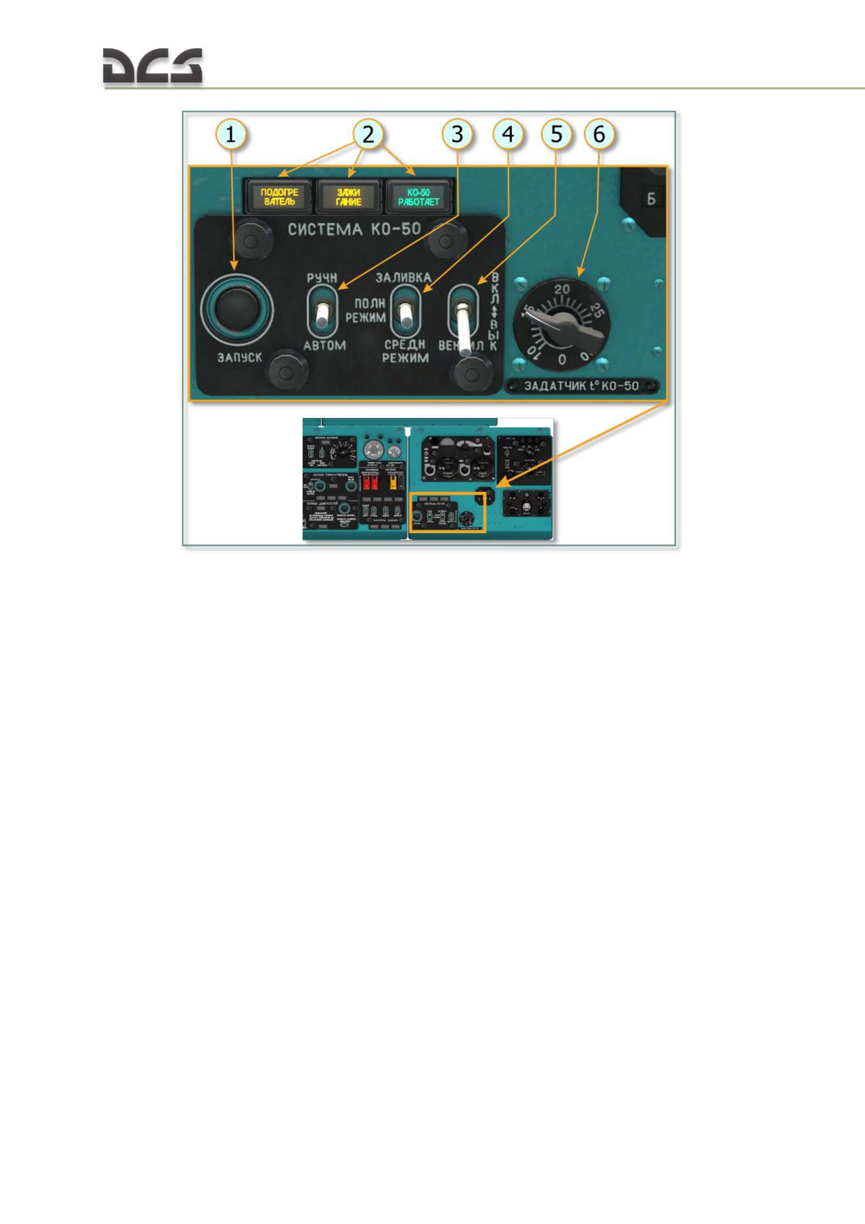
Fig. 7.32. KO-50 control panel
1. КО-50 start button
4. The ЗАЛИВКА - ПОЛН РЕЖИМ - СРЕДН
2. KO-50 status panel:
РЕЖИМ (PRIME-HIGH-MEDIUM OUTPUT
MODE):
- ПОДОГРЕВАТЕЛЬ (PREHEATER) -
indicates engagement of the fuel preheater;
-ПОЛН РЕЖИМ - СРЕДН РЕЖИМ (HIGH
- ЗАЖИГАНИЕ (IGNITION) - indicates
-MEDIUM MODE) positions are used for
operation of the igniter;
setting high and medium heat output modes
- КО-50 РАБОТАЕТ - KO-50 IS
correspondingly, when operating in manual
OPERATING
mode;
-ЗАЛИВКА (PRIME) position is used for
3. РУЧН - (НЕЙТРАЛЬ) - АВТОМ (MANUAL -
system maintenance and not modelled in this
NEUTRAL -AUTO ) KO-50 modes switch
game.
5. Fan switch
6. Temperature knob
190
7.7.2. Enabling the KO-50 heater in automatic mode
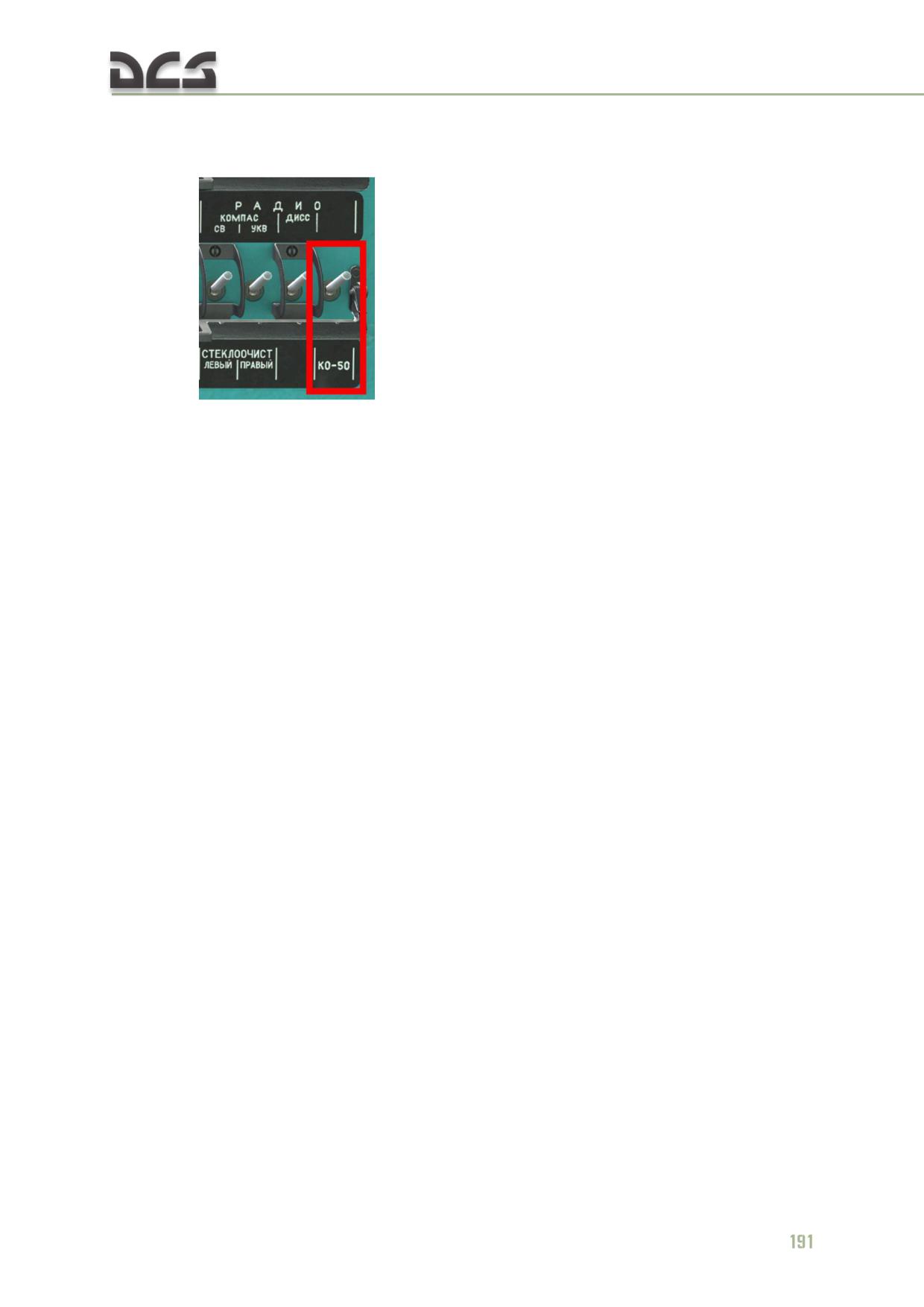
Enable the КО-50 ACB on the right over head circuit breaker panel
;
set the mode switch on the heater control panel into the АВТОМ.
(AUTOMATIC) position (Fig. 7.32, 3);
set required temperature by the temperature knob (Fig. 7.32, 6);
press the ЗАПУСК (START) button (Fig. 7.32, 1), as a result on the heater
control panel the ПОДОГРЕВАТЕЛЬ (PREHEATER) signal panel goes on.
When fuel temperature reaches
70±5°С, the ПОДОГРЕВАТЕЛЬ
(PREHEATER) panel goes off and the ЗАЖИГАНИЕ (INGITION) and КО-50
РАБОТАЕТ (KO-50 IS OPERATING) lights are on. After not more than 40
seconds, the ЗАЖИГАНИЕ (IGNITION) panel should go off, this will
indicate sustainable combustion of the fuel in the KO-50 heater.
7.7.3. Enabling the KO-50 heater in manual mode
Enable the KO-50 ACB on the right over head circuit breaker panel panel;
set the mode switch on the KO-50 control panel to the РУЧН (MANUAL)
position;
set the heat output mode switch to the ПОЛН.РЕЖИМ (HIGH OUTPUT) or
СРЕДН.РЕЖИМ (MEDIUM OUTPUT) position;
press the ЗАПУСК (START) button.
The following stages of operation are equal to those in automatic mode.
NOTE: Before disabling the heater, to cool it faster, set the ВЕНТИЛ. (VENTILATION) switch to the
ВКЛ. (ENABLE) position for 3..10 minutes (no need to use it in game).
7.7.4. Using the KO-50 heater in ventilation mode
When the heater is supposed to be used during summer time for cabins ventilation,
enable the KO-50 ACB and set the ВЕНТИЛ. (VENTILATION) switch to the ВКЛ.
(ENABLE) position. Air is supplied, using the same air channels as during winter time.
7.7.5. Switching OFF the KO-50 heater
Set the РУЧН.- АВТОМ. (MANUAL-AUTO) switch into the neutral position;
after landing, disable corresponding ACB.
7.8. Lighting equipment
The helicopter is equipped with lighting equipment, which supposed to be used
during day and night flights. Ligthing equipmet includes exterior and interior lighting
equipment.
7.8.1. Exterior lighting equipment
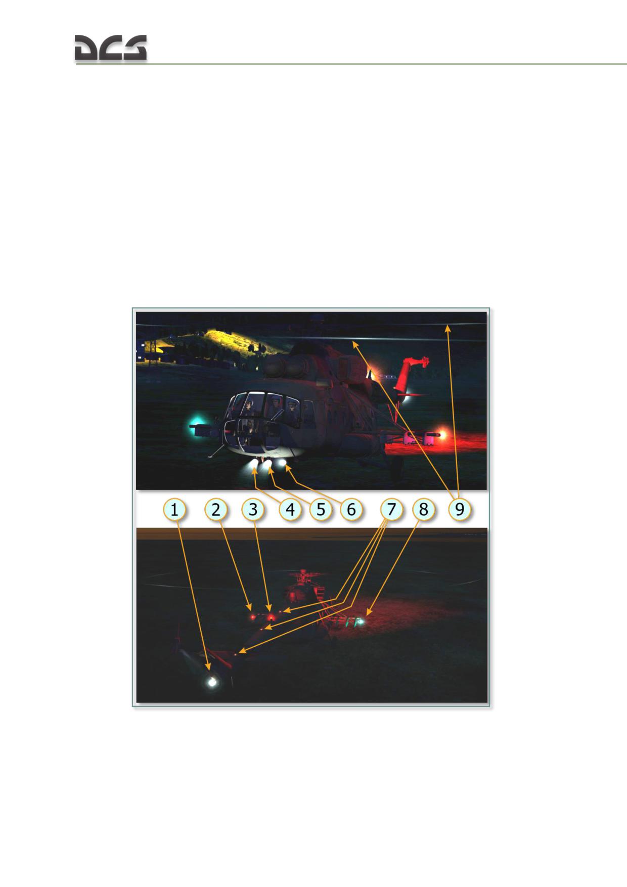
Exterior lighting equipment consists of, Fig. 7.33:
two FPP-7M search/landing lights;
FR-100 taxi light;
MSL-3 anti-collision light;
BANO-45 navigation lights and the KhS-39 tail light;
OPS-57 formation lights;
blade tip lights.
Fig. 7.33. Exterior lighting equipment
1. KhS-39 tail light
6. FR-100 taxi light
2. Left BANO-45 navigation light (red)
7. OPS-57 formation lights
3. MSL-3 anti-collision light
8. Right BANO-45 navigation light (green)
4. Right pilot’s FPP-7M light
9. Blade tip lights
192
5. Left pilot’s FPP-7M light
Electrical circuits of the exterior lighting system are connected via ACBs, located on
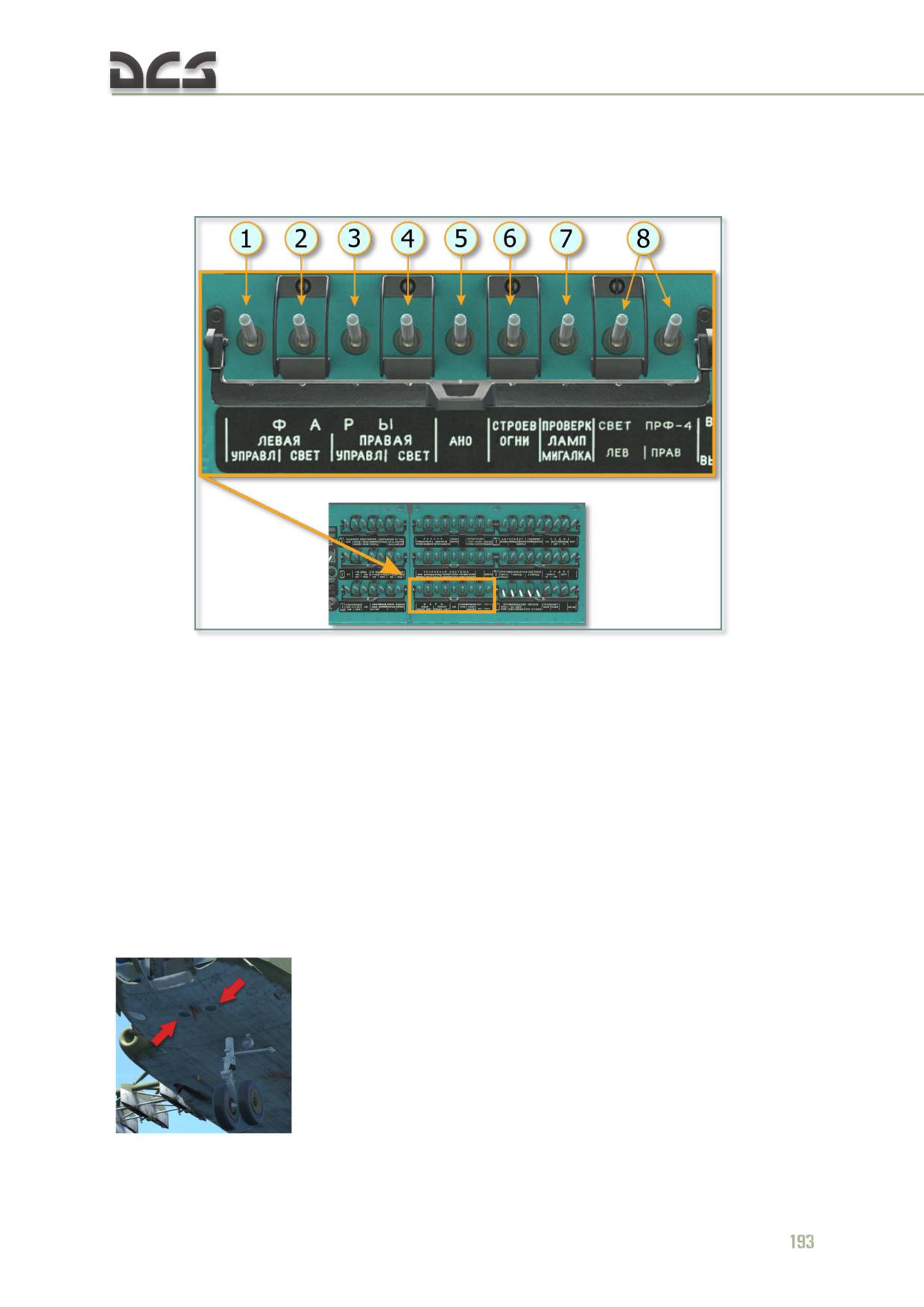
the right over head circuit breaker panel, Fig. 7.34:
Fig. 7.34. The ACBs of the exterior lighting system
1. Left search/landing light, light control circuit
4. Right search/landing light, incandescent
2. Left search/landing light, incandescent light
light bulb circuit
bulb circuit
5. Navigation lights’ supply circuit
3. Right search/landing light, light control
6. Formation lights’ supply circuit
circuit and incandescent light bulb circuit of
7. МИГАЛКА (FLASH) circuit
taxi light
8. PRF-4 lights (on the main landing gear
struts, not implemented)
The ACB of the anti-collision light is located on the right side console (see below).
FPP-7M search/landing light
There are two FPP-7 search/ landing lights, mounted under the helicopter nose
section to the right and left of the longitudinal centerline (Fig. 7.33 , 4, 5)
. The lights are designed for search operations during low
visibility conditions, searching and illuminating landing sites and taxi areas at night.
The lights can be elevetade at angle from 0 (down) to up to 120° and turned at any
angle in azimuthal direction or can be retracted.
The right FPP-7M lights is connected to the battery circuit, and the left one to the
rectifier bus. In the light control and incandescent light bulb circuits are automatic
circuit breakers, located on the right over head circuit breaker panel
Turning on the lights and supplying electrical power to the extension/retraction and
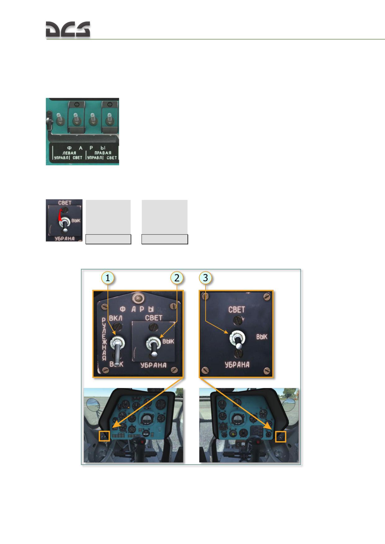
rotation switches is done with help of two ФАРЫ СВЕТ - ВЫК - УБРАНА (LIGHT ON
- OFF - RETRACTED) switches, when they are set to the СВЕТ (LIGHT) position
[LShift + L]
/
[RShift + L]
. These switches are located on separated
panels, attached to the left of the pilot’s instrument panel and to the right of the co-
pilot’s one (Fig. 7.35, 2 ,3):
Fig. 7.35. Lights controls
194
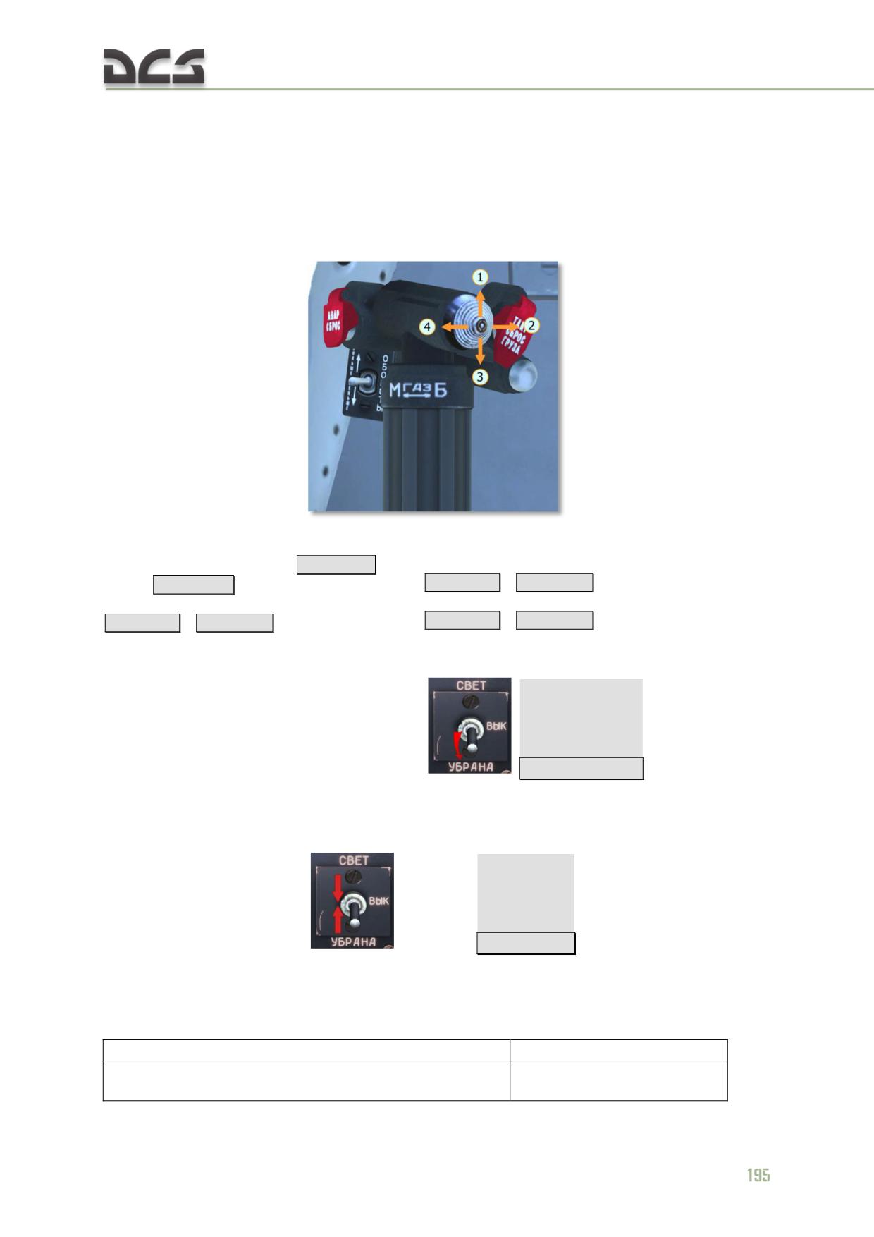
1. Left pilot’s FR-100 taxi light switch
3. Right pilot’s FPP-7M search/landing light
2. Left pilot’s FPP-7M search/landing light
control switch
control switch
Extension, retraction (beam elevation control), rotation to the left and to the right
(azumith control) is performed with help of two five-position hats, located on the
collectives, Fig. 7.36:
Fig. 7.36. Search/taxi light beam controls
1. Light (beam) forward (up)
[LShift + 8]
(left
3. Light (beam) backward (down)
light) /
[RShift + 8]
(right light)
[LShift + 7]
/
[RShift + 7]
2. Light (beam) rotation to the right
4. Light (beam) rotation to the left
[LShift + 0]
/
[RShift + 0]
[LShift + 9]
/
[RShift + 9]
When the ФАРЫ СВЕТ - УБРАНА (LIGHT ON -OFF - RETRACTED) switches are set
to the УБРАНА (RETRACTION) position
[not assigned]
, lights turn off
and retract automatically. During retraction, the lights are automatically returning to
their initial position in relation to the helicopter centerline. Fully extended and
retracted positions are locked with help of limit switches.
The ВЫК (OFF) position
(neutral)
[LShift + ;]
(first press) is used for
preserving position of the light, when light is OFF. In game, this is a default position.
FPP-7M FEATURES are shown in Table 7.2
Table 7.2
Nominal supply voltage, V
27
Current, consumed by the each electrical motor, А, not
0,7
more
Consumed power, Watt, not more
480
Nominal luminous intensity, cd
300000
Extension elevation angle, degrees
from 0 to 120
Rotation angle (azumith)
not limited
Weight, kg, not more
3
FR-100 taxi light
The light is used for illuminating surface while taxiing. The taxi light is located on the
lower part of the fuselage
(in real life, used for saving service
life of the landing lights).
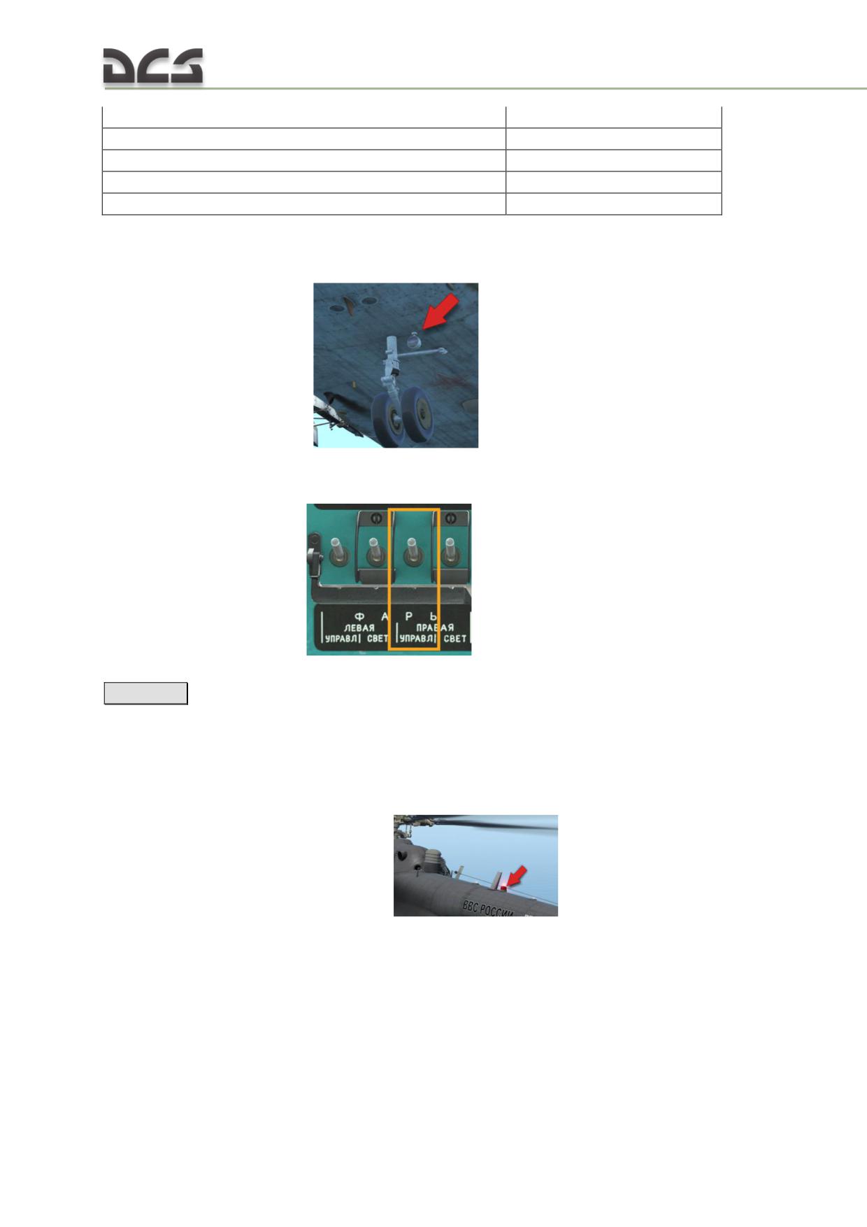
It is supplied by the battery bus via the ФАРЫ ПРАВАЯ УПРАВЛЕНИЕ (LIGHTS
RIGHT CONTROL) ACB
, and turns on by the ФАРЫ
-
РУЛЁЖНАЯ (LIGHTS -TAXI) switch, located near the left FPP-7 switch, (Fig. 7.35, 1)
[RCtrl + L]
MSL-3 anti-collision light
The MSL-3 anti-collision light is designed to indicate the direction of travel and the
position of the helicopter at night, during inclement weather, and in poor visibility. It
is used to indicate the place of helicopter in case of emergency landing. The MSL-3
light is located on the top of the tail,
. This light is turned on by
196
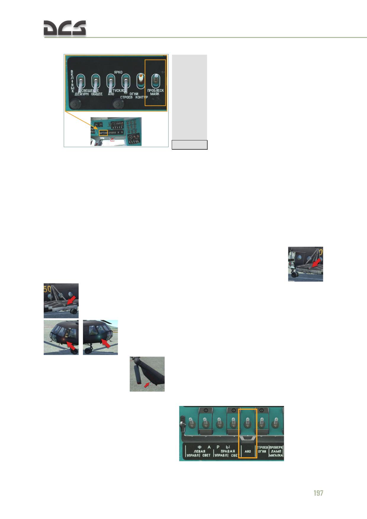
the ПРОБЛЕСК МАЯК (ANTI-COLLISION LIGHT) ACB, located on the right electrical
panel
[RCtrl + 6]
This light is connected to the battery bus (on some models, for example Mi-8MTVx -
to the rectifier bus).
To avoid overheating, do not operate the anti-collision light for more than 10 minutes
on the ground if the main rotor is not turning (not implemented).
Navigation lights
Navigation lights are used for indication of helicopter position.
On the helicopter the BANO-45 type navigation lights and the KhS-39 tail light are
installed.
The red and green navigation lights are installed on the weapon rack tips
or on the starboard and port sides of the nose part of the fuselage
(if weapon racks and armor are not mounted), KhS-39 is
installed on top of the tail
Navigation lights are supplied via the "АНО" (NAVIGATION LIGHTS) ACB, located on
the right over head circuit breaker panel
. Navigation
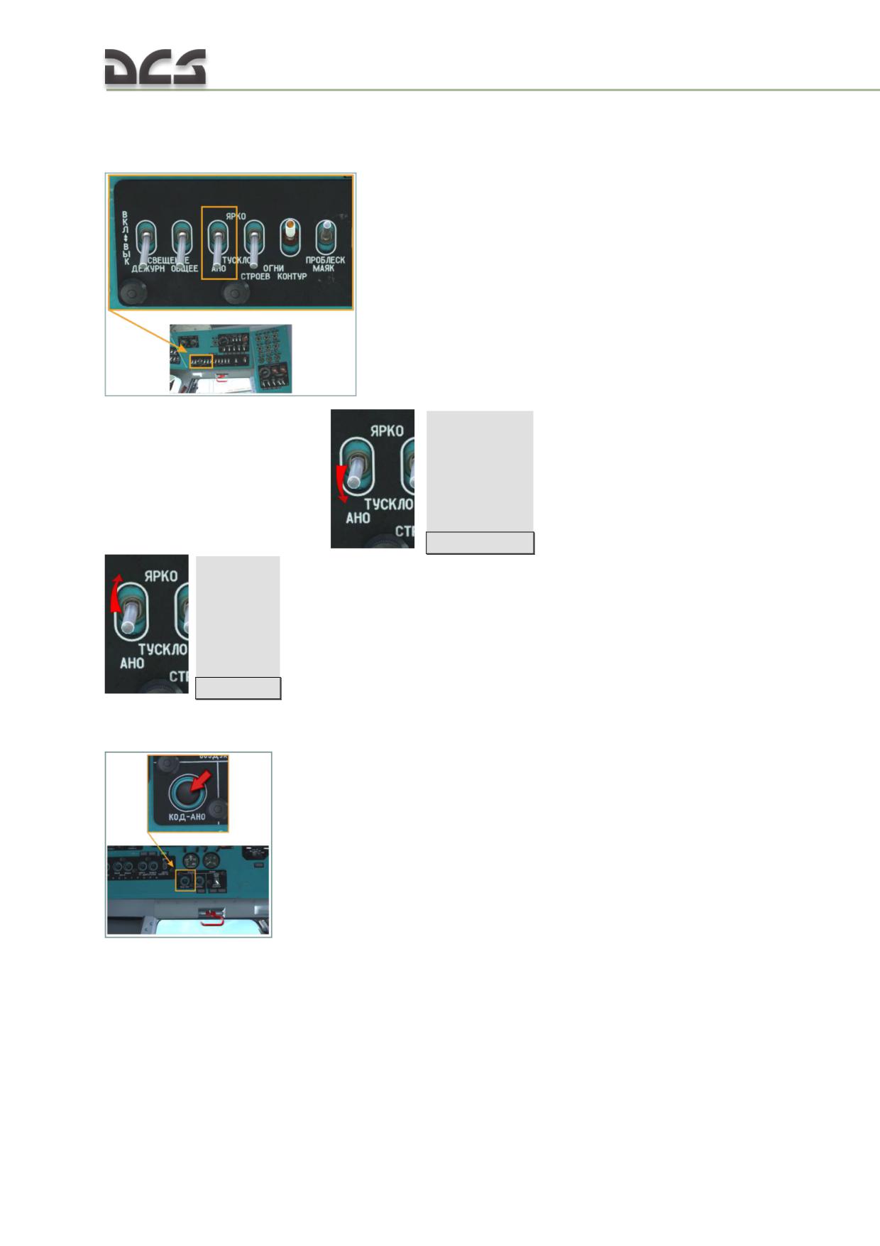
lights are controlled (enabling and selection of the illumination intensity) by the АНО
ТУСКЛО -(neutral)- ЯРКО (NAVIGATION LIGHT DIMINISHED- neutral - BRIGHT)
switch, located on the electrical panel of the right side console.
:
ТУСКЛО (DIMINISHED) -
[RCtrl
+
1]
(down), ЯРКО (BRIGHT) -
[RCtrl + 2]
(up). Neutral position turns of all navigation lights.
The arbitrary light signal codes can be given with help of the "КОД-АНО"
(NAVIGATIONAL LIGHT CODE) button, located on the left side console
198
OPS-57 Formation lights
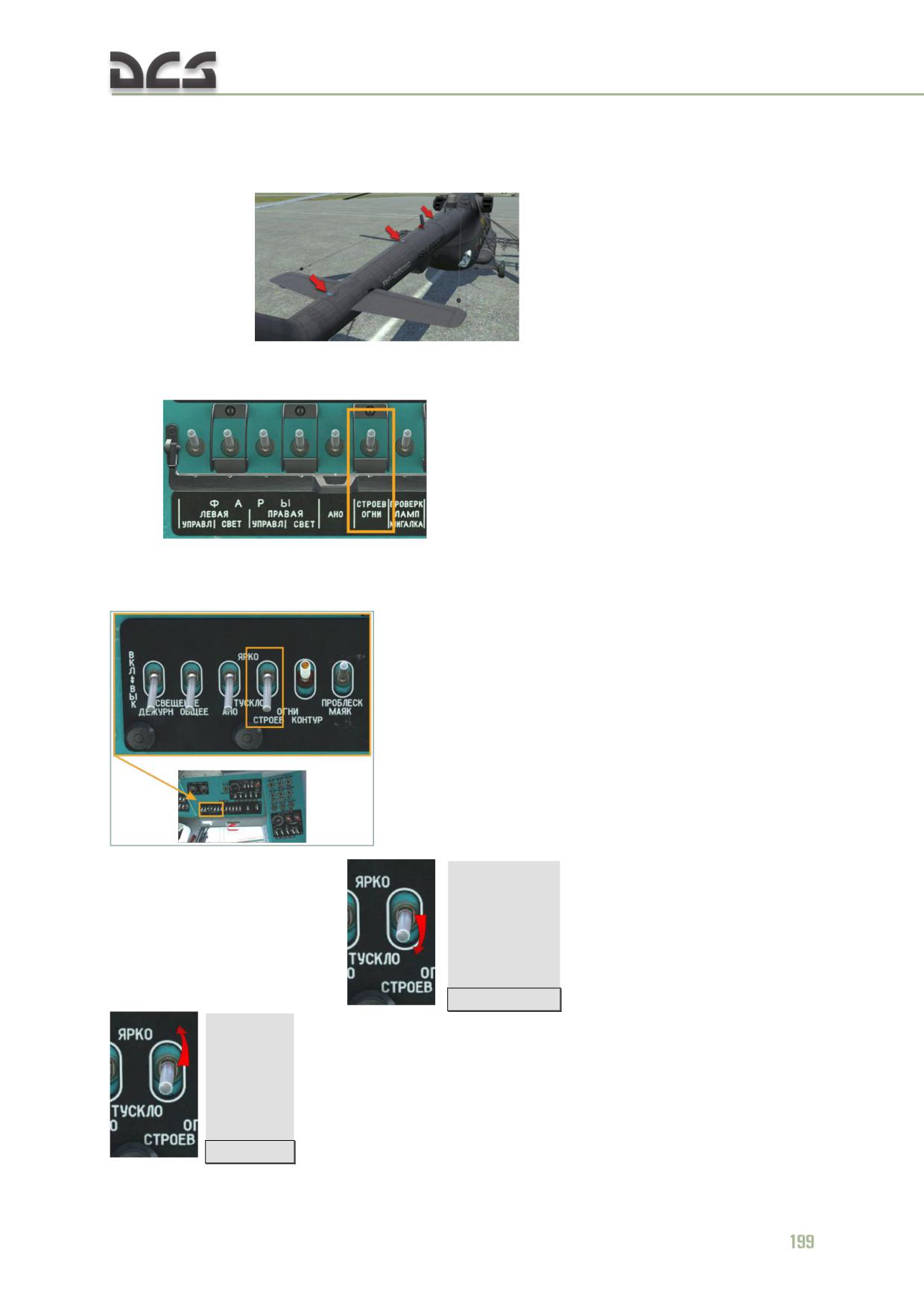
The OPS-57 formation lights are designed to assist pilots in maintaining formation
while flying at night and in poor visibility conditions.There are three formation lights
on the helicopter
The formation lights are supplied by the recitifier bus via the СТРОЕВ ОГНИ
(FORMATION LIGHTS) ACB, which is installed on the right over head circuit breaker
panel
. These lights are controlled (enabling and
selection of illimination intensity) with help of the ОГНИ СТРОЕВ ТУСКЛО
-
(нейтраль)- ЯРКО (NAVIGATION LIGHTS DIMINISHED
-(neutral) -BRIGHT),
installed
on
the
electrical
panel
of
the
right
side
console
:
ТУСКЛО (DIMINISHED) -
[RCtrl
+
3]
(down), ЯРКО (BRIGHT) -
[RCtrl + 4]
(up) . Neutral position turns of all formation lights.
Blade tip lights
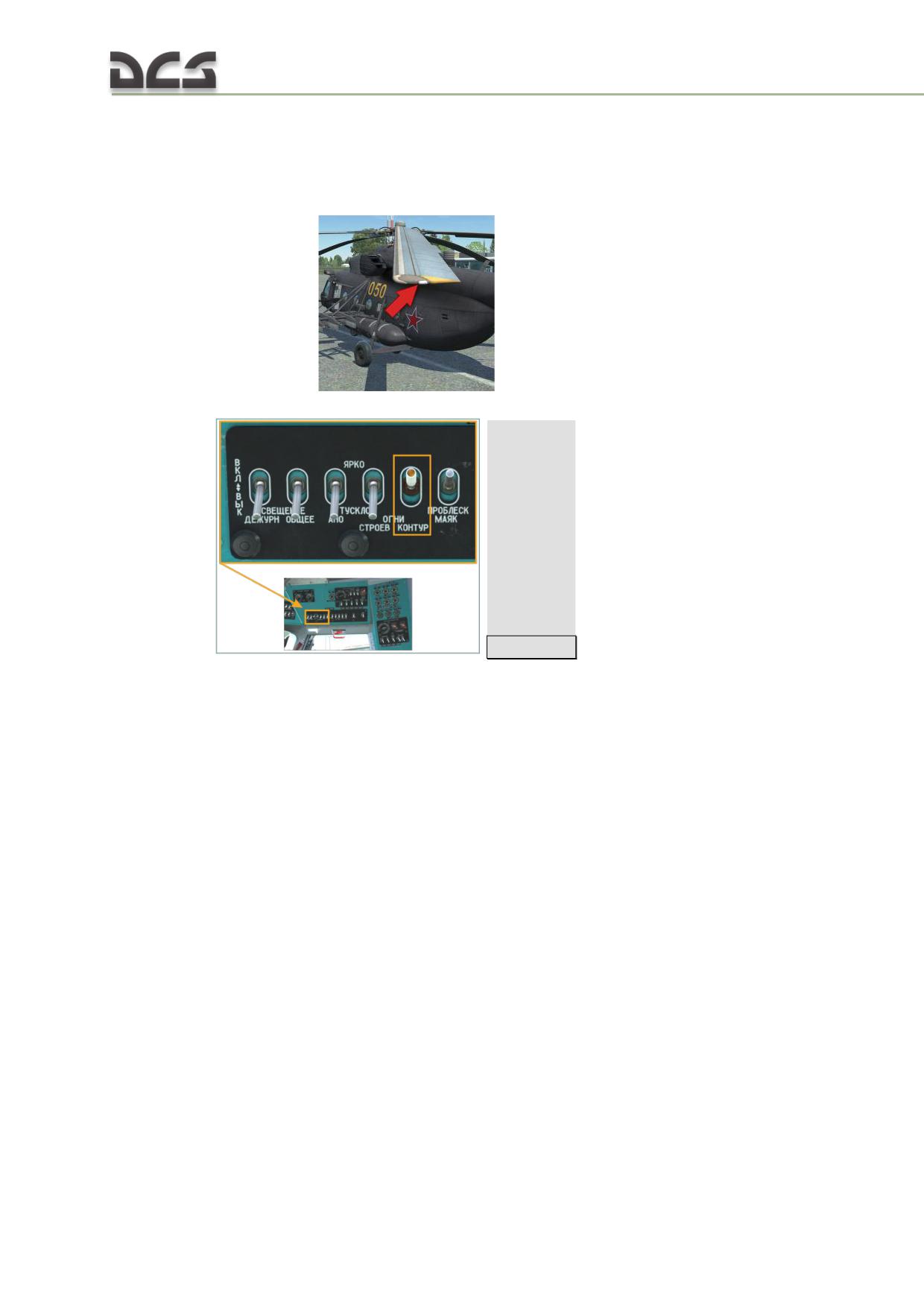
The blade tip lights are used to indicate the position of the main rotor blades for
movement of the helicopter at night or in poor visibility. A blade tip light is installed
inside a removable fairing on each
main rotor blade tip cap.
. This lights are enabled by the ОГНИ
КОНТУР (BLADE TIP) switch, which is installed on the electrical panel of the right
side console
[RCtrl + 5]
Blade tip lights are powered by the 115 VAC bus through the TR 115/7.5V
transformer.
7.8.2. Interior lighting equipment
The interior lighting system includes interior illumination of the cockpit, cargo cabin
and various compartments, and in-helicopter light signalization system.
Cockpit illumination
Cockpit illumination consists of:
player flashlight;
illumination of pilots’ working space;
red backlight system.
PLAYER’S FLASHLIGHT
200
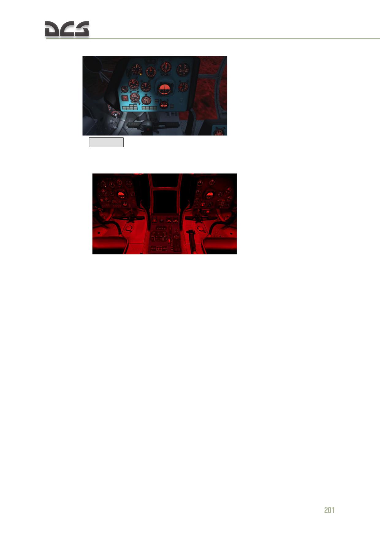
Player’s flashlight is used to ease navigation in the cockpit during night missions with
cold start
. It can be turned on/off by
pressing the
[LAlt + L]
keys and controlled by the mouse.
ILLUMINATION OF PILOTS’ WORKING SPACE
Cockpit is illuminated by the white (main) and red (backup) light with help of two
dome lights
, installed on the cockpit
ceiling on both sides of the helicopter. Each dome light contains two bulbs - one is
white and the other is red. These lights turn on by the ПЛАФОН КРАСНЫЙ (DOME
LIGHT RED) (up) - (neutral)-БЕЛЫЙ (WHITE) (down) switch. Neutral position turns
off corresponding dome light. This switches are located on the triangular panels,
Fig. 7.37.
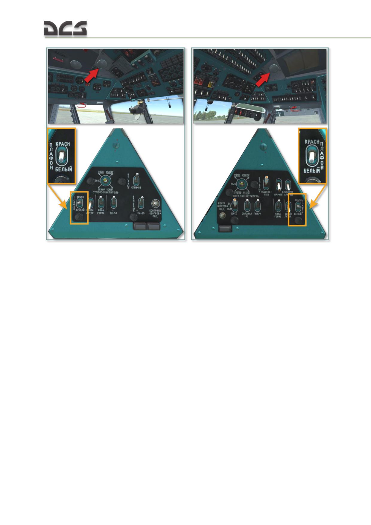
Fig. 7.37. Backup dome lights
RED LIGHT BACKLIGHTING SYSTEM
Red light backlighting system is used for backlighting various instruments and
gauges on the instrument panels, central panel and electrical panel (right rear
console).
Red light backlighting system of the central panel and electrical panel is divided on
two groups. Group I is connected to the rectifier bus and group II to the battery bus.
Red light backlighting system has no ACBs. Turning on of both groups and backlight
intensity adjustment is performed with help of rheostats. To limit maximum voltage
applied to red backlight system, rheostats have limiters.
Red light backlighting for the left overhead circuit breaker panel, left-side console,
left triangular panel, left overhead console, pilot’s instrument panel, KI-13 compass,
left pilot's and cargo cabin’s intercoms and left FPP-7M control panel is controlled by
the КРАСНЫЙ ПОДСВЕТ - ГРУППА 1 (RED BACKLIGHT -GROUP1) and КРАСНЫЙ
202
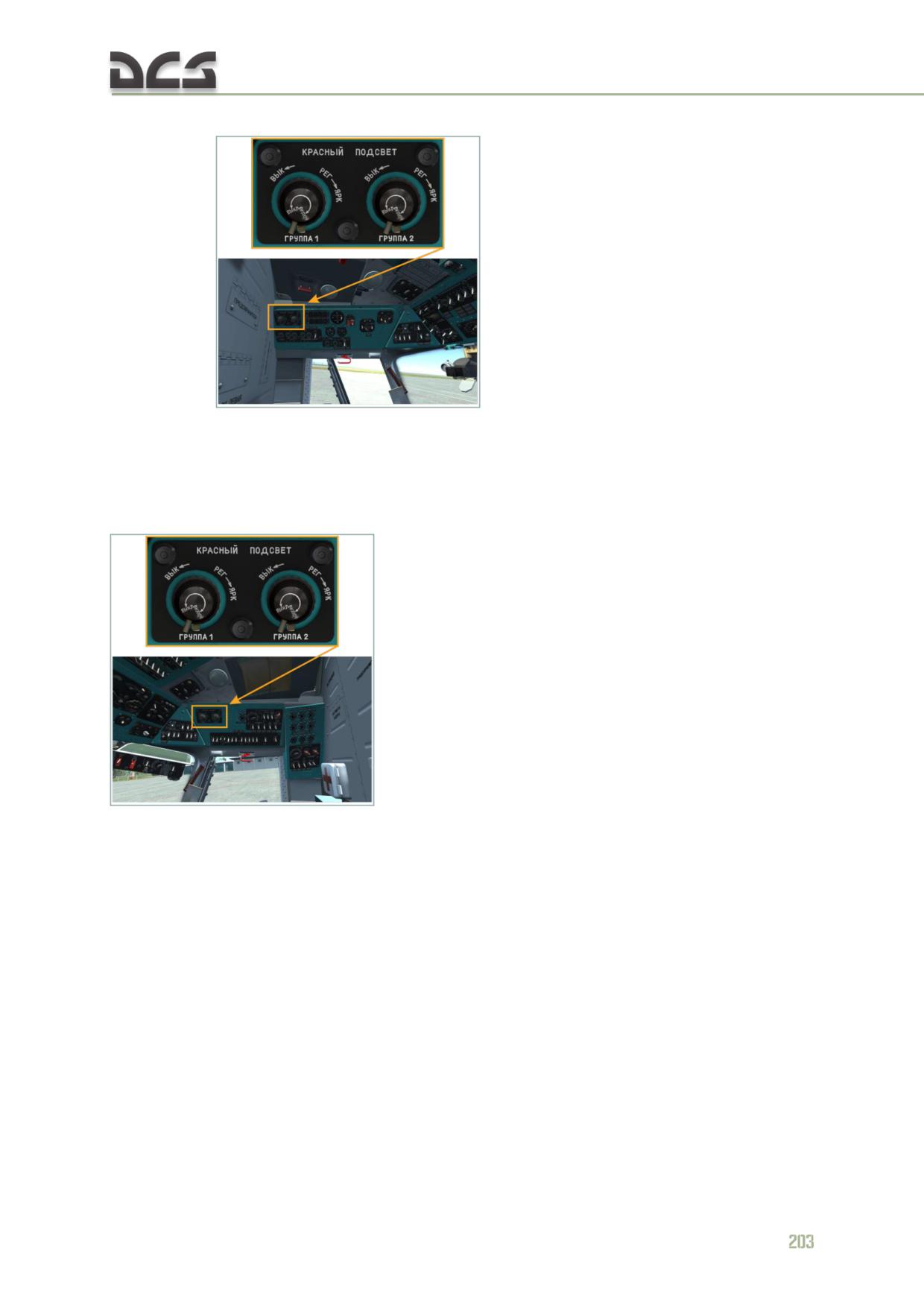
ПОДСВЕТ - ГРУППА 2 (RED BACKLIGHT - GROUP2) rheostats, installed on the left
side console
Red light backlighting for the weapon console, R-863 radio control panels, right over
head circuit breaker panel, right side console, right triangular panel, copilot’s
instrument panel and right FPP-7 control panel is controlled by the КРАСНЫЙ
ПОДСВЕТ - ГРУППА 1 (RED BACKLIGHT -GROUP1) and КРАСНЫЙ ПОДСВЕТ -
ГРУППА 2 (RED BACKLIGHT - GROUP2) rheostats, installed on the right side console
Red light backlighting of the central autopilot console, center overhead console, AC
power control console, R-828, UV-27, Yadro-1M control panels, and panels installed
in the doorway, is controlled by the КРАСНЫЙ ПОДСВЕТ - ГРУППА 1 (RED
BACKLIGHT -GROUP1) and КРАСНЫЙ ПОДСВЕТ - ГРУППА 2 (RED BACKLIGHT -
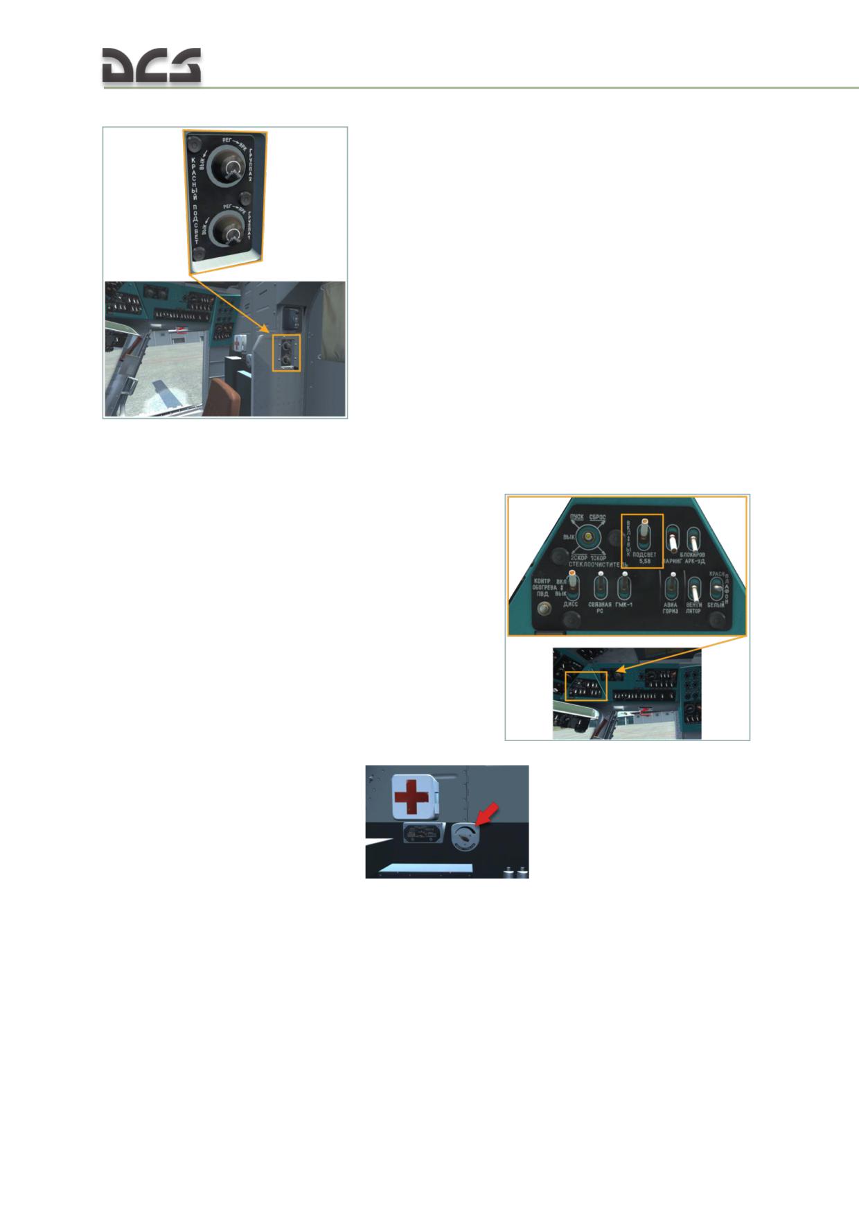
GROUP2) rheostats, located on the right side of the cockpit doorway
The
5.5V red backlighting (the "Подсвет
5,5V" (Backlight
5.5V)) system was
designed to backlight gauges and instruments, installed on the Mi-8MT as part of
modernization of the Mi-8T). I can be enabled by the ПОДСВЕТ 5,5В (BACKLIGHT
5.5V) switch, installed on the right triangular panel
Backlight intensity is regulated by the TR-100 transformer, mounted on the right
stand (behind the copilot’s back)
. Gauges, backlighted by the
5.5V backlighting system, are shown on Fig. 7.38:
204
Fig. 7.38. Instruments backlighted by the "Подсвет 5,5V" (Backlight 5.5V) system
Supply circuits of the red 5.5V backlight are connected to the 115 VAC generator
bus.
Illuminaton of cargo cabin and technical compartments
This function is not implemented.
In-helicopter light signalization system
Monitoring of the helicopter’s systems and units, besides dedicated instruments, is
performed with help of in-helicopter light signalization system.
Signalization is done with help of light panels with light filters of red, yellow and
green color, located on the instrument panels, central panel and electrical panel. For
some light panel groups, some special operating modes are intended (FLASHING,
DAY-NIGHT) and lamps checking.
The “MIGALKA” (FLASH) system is developed for attracting pilot’s attention to the
light panel, indicating malfunction or failure of some system, unit and informing him
about emergency situations (fire, icing, excessive engine vibration, operation of
backup systems, 270 liters of fuel remains in fuel tank). The operating principle of
the “MIGALKA” (FLASH) is based on lamps, operating in impulse mode. Flashing
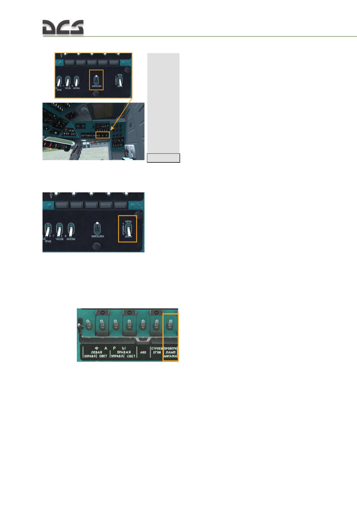
mode is enabled with help of a switch, located on the right side console
[RCtrl + -]
THE "ДЕНЬ-НОЧЬ" (DAY-NIGHT) system is intended to reduce illumination intensity
for some intruments and light panels. This is done by setting the "ТАБЛО ДЕНЬ-
НОЧЬ" (PANEL DAY-NIGHT) switch, located on the right side console
, to the "НОЧЬ" (NIGHT) (up) position. As a result,
light panels, connected to the ДЕНЬ-НОЧЬ" (DAY-NIGHT) system will illuminate with
half-intensity.
WARNING LAMPS CHECKING SYSTEM
To enable warning lamps checking system pilot must enable:
ACB
"ПРОВЕРКА
ЛАМП
МИГАЛКА"(LAMP
TEST
FLASH)
,
set the "ПРОВЕРКА СИГНАЛ ЛАМП - МИГАЛКИ" (WARN LTS - TEST-
FLASH) switch, located on central panel, into "СИГНАЛ ЛАМП" (WARN
206
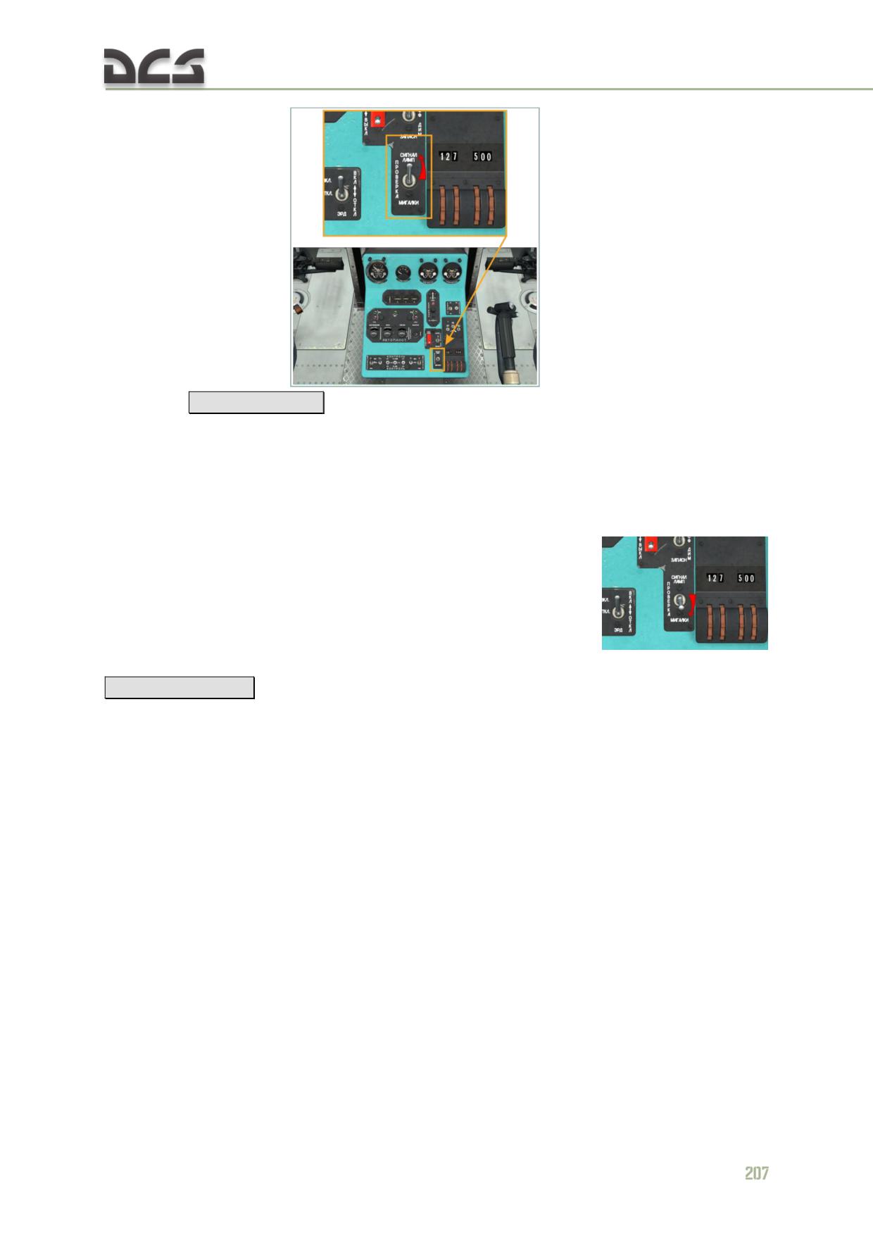
LTS)
(up)
position
[LAlt + LCtrl + B]
As a result all signal panels will be on, except those, which are connected to the
"МИГАЛКА" (FLASH) system, and those, which are on, when corresponding
equipment is connected (for example, АЭРОДРОМНОЕ ПИТАНИЕ (GROUND
POWER)).
When the switch "ПРОВЕРКА СИГНАЛ ЛАМП - (neutral) - МИГАЛКИ" (WARN LTS -
TEST- FLASH) is set to "ПРОВЕРКА МИГАЛКИ" (FLASH)
(down)
[LAlt + LCtrl + V]
, all light panels, connected to the "МИГАЛКА" (FLASH) system will
be operating in impulse mode (flashing).
Light panels, connected to the MIGALKA (FLASHING) system are shown on
Fig. 7.39:
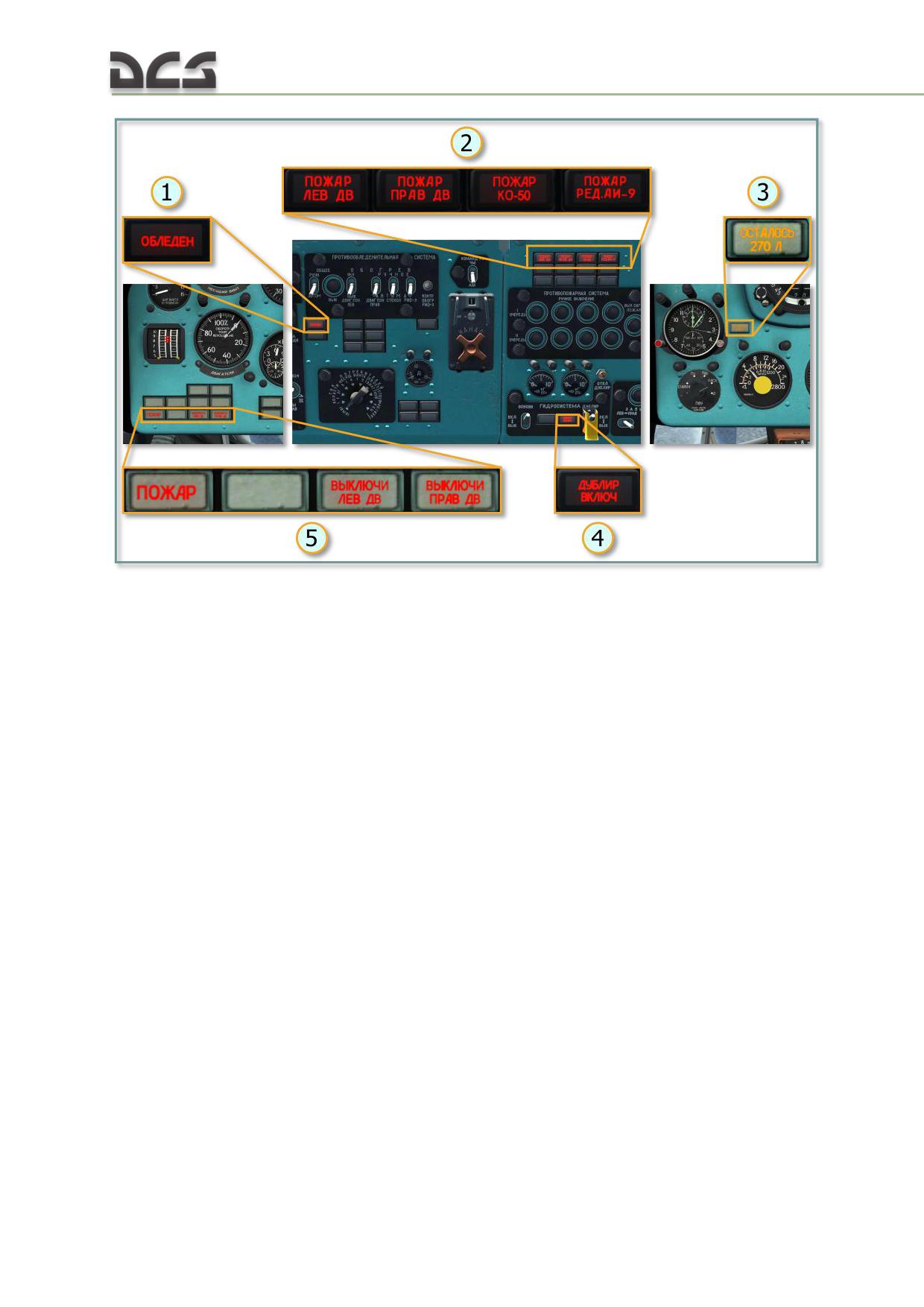
Fig. 7.39. Light panels, connected to the MIGALKA (FLASH) system
1. ОБЛЕДЕНЕНИЕ (ICING)
3. ОСТАЛОСЬ 270л (270 L
(started/continuing)
REMAINS)(emergency fuel)
2. Fire in compartments (from left to right):
4. ДУБЛИР ВКЛЮЧЕНА (BACKUP IS ON)
ПОЖАР ЛЕВ ДВ (FIRE LEFT ENGINE)
(indicates that backup hydraulic system is
(in left engine's compartment)
operating, it automatically means failure in the
ПОЖАР ПРАВ ДВ (FIRE RIGHT
utility hydraulic system)
ENGINE) (in the right engine’s
5. Fire annunciator ПОЖАР (FIRE), then -
compartment)
ВЫКЛЮЧИ ЛЕВ ДВ (STOP LEFT ENGINE),
ПОЖАР КО-50 (FIRE KO-50) (fire in
ВЫКЛЮЧИ ПРАВ ДВ (STOP RIGHT ENGINE)
the heater)
(signalization of excessive engine vibration,
ПОЖАР РЕД АИ-9 (FIRE
that can damage corresponding engine)
TRANSMISSION AI-9) (in the
transmission compartment of the APU
and in service fuel tank)
Circuits for checking warning lamps functionality, "МИГАЛКА" (FLASH) and "ДЕНЬ-
НОЧЬ" (DAY-NIGHT) systems are connected to battery bus via the ПРОВЕРКА ЛАМП
МИГАЛКА (LAMP TEST FLASH) ACB on the right over head circuit breaker panel.
7.9. Registration of the flight parameters and voice recording
7.9.1. SARPP-12DM flight data recorder
This system is not implemented, but corresponding light panel and switch are
animated.
The SARPP-12DM flight data recorder is designed to record the flight parameters of
the helicopter under normal and emergency conditions.
208
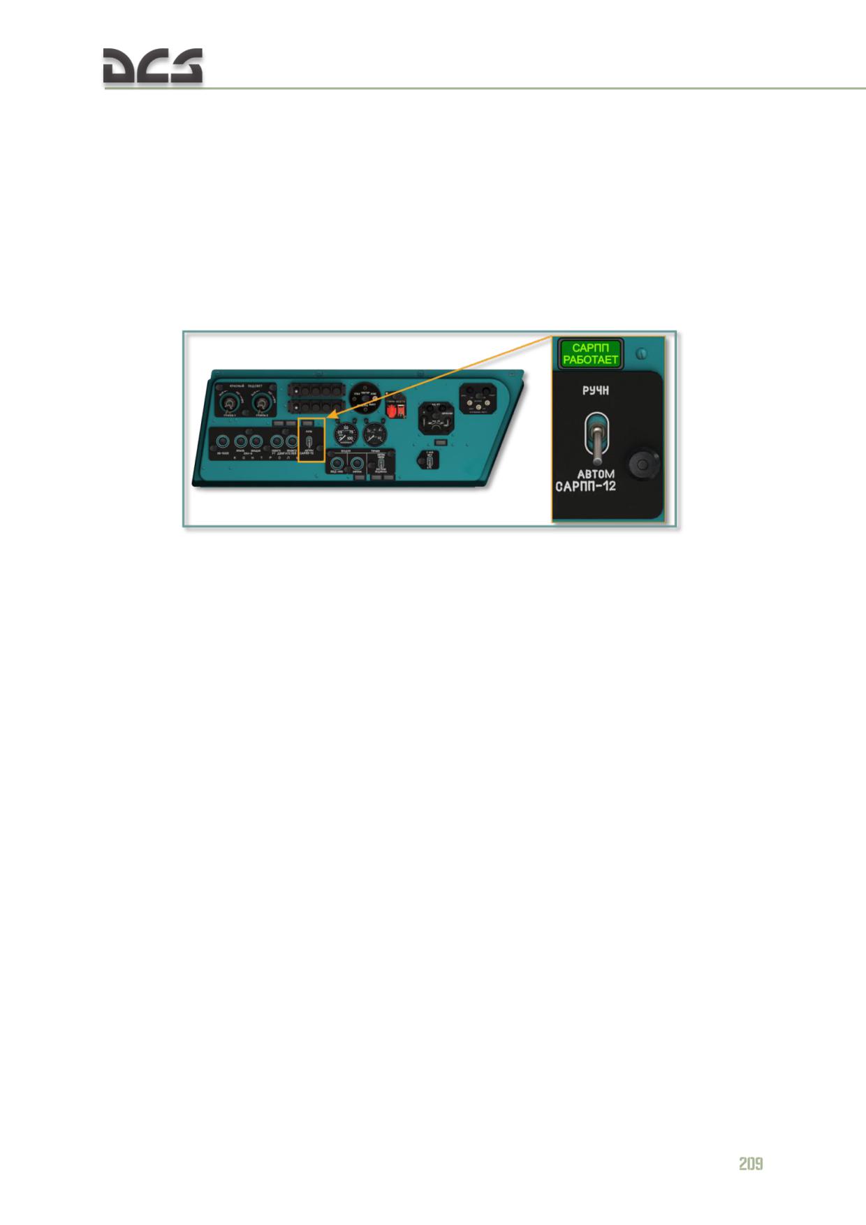
The system continuously records the helicopter’s barometric altitude, indicated
airspeed, the position (tilt and height) of the main rotor swashplate, the main rotor
RPM, and the helicopter pitch and roll angles. The system also records nine event-
driven parameters. The trigger events include low fuel emergency, failure of any fuel
boost pump, engine emergency power engagement, detection of a fire in any deck
compartment, main hydraulic system failure, backup hydraulic system failure, loss of
oil pressure in the main transmission, engagement of engine and particle separator
anti-ice system (right engine only), and engagement of rotor deice system. All data is
provided to the recorder via sensors, pressure switches, and/or transducers installed
in the monitored systems.
Fig. 7.40. SARPP-12D1M FDR power switch and indicator light, left side panel
The recorder may be turned on manually or set for automatic operation using the
"САРПП-12Д1М "РУЧН - АВТОМ"" (FLIGHT RECORDER) switch on the pilot’s left
side panel. When the switch is placed in the AUTO (down) position, the system is
turned on automatically just after takeoff, when the AM-800K microswitch in the left
main landing gear strut is activated. The microswitch activates when the weight is
removed from the main landing gear. If the film transport and light-beam in the K12-
51DM data storage unit are operational, the "САРПП РАБОТАЕТ" (SARPP WORKING)
indicator light, located near the switch, will blink. In AUTO mode, the system
activates only if there is sufficient pressure in the main or reserve hydraulic system
The flight recorder system consists of:
K12-51DM data storage unit;
УсС-4-1M UsS-4-1M matching device;
sensors.
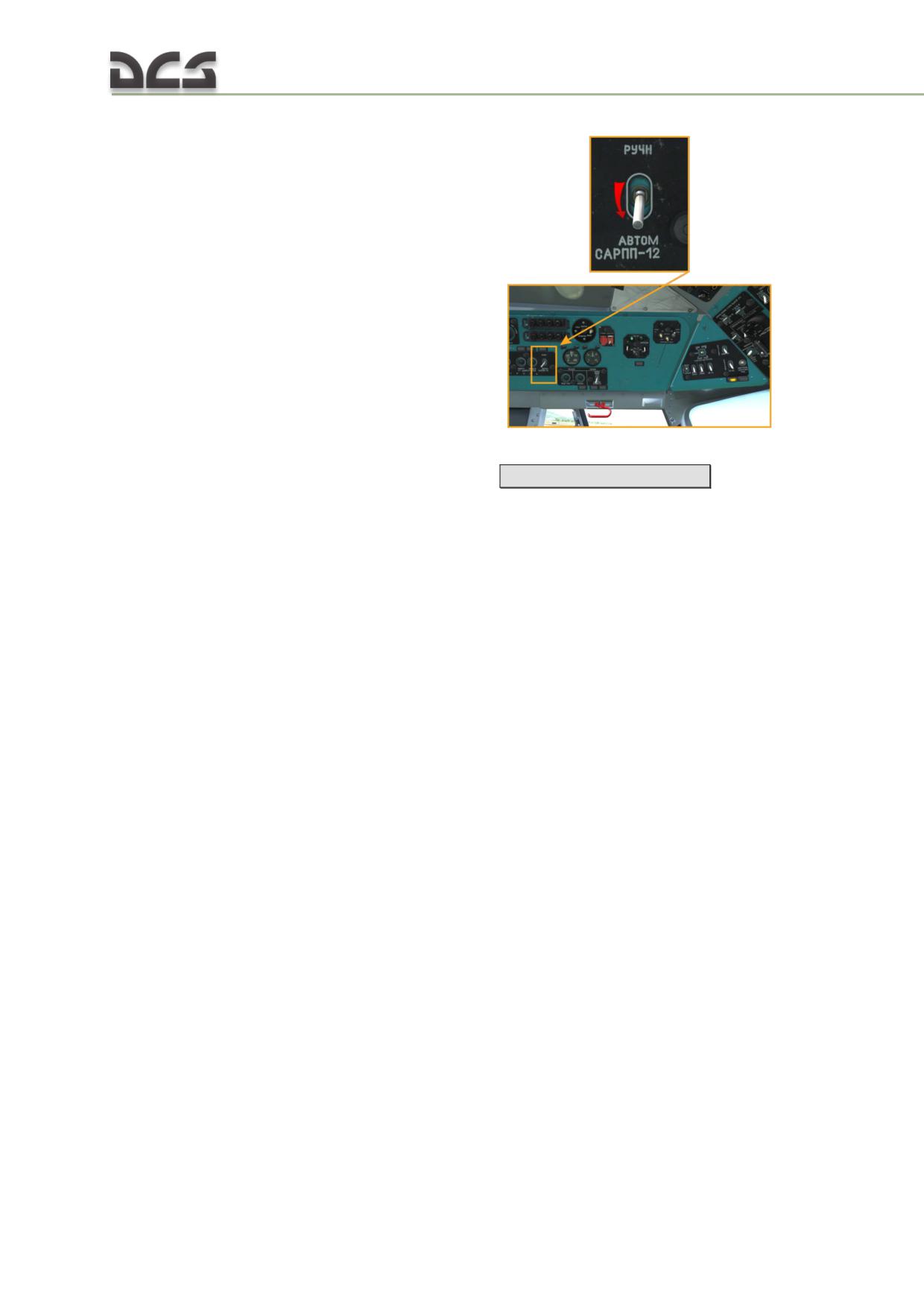
The SARPP-12 system is enabled by the "САРПП-12Д РУЧН-АВТОМ" (SARPP-12D
MANUAL-AUTO) switch on the left side console
To enable the system before engine start, set the corresponding switch to the
"АВТОМ." (AUTO) or РУЧН (MANUAL) position
[LAlt + LCtrl + LShift + 6]
When this switch is set to the АВТОМ. (AUTO) position, the flight recorder begins
operating only if there is enough pressure in the utility or backup hydraulic system,
or if limit switches in the main landing gear struts trigger when helicopter is airborne.
If set to the РУЧН. (MANUAL), recorder engages immediately, indendently on
pressure in the hydraulic systems.
Data storage unit in armored container and matching device are installed in the tail
boom.
The SARPP-12DM system is supplied by the 27-29V onboard DC bus, and in
emergency mode by the battery bus, through PM-10 SARPP ACB, located on the ACB
panel.
Continuous operating time of the SARPP-12 system is not less than 5.5 hours.
7.9.2. P-503B voice recorder
Not implemented, but corresponding switch is animated.
Voice recorder is designed for recording voice information of the helicopter’s pilot,
transmitted over radios and intercoms, as well as information given to the pilot.
210
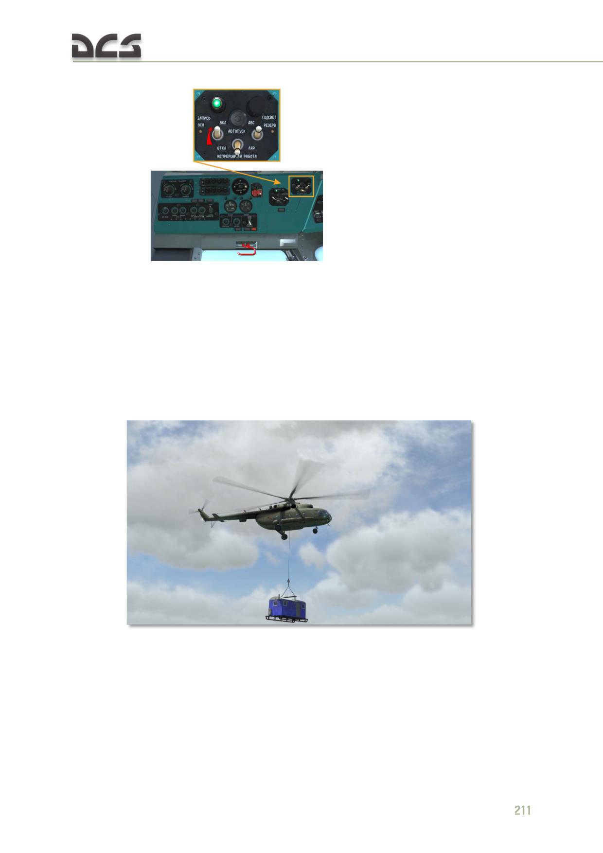
The voice recorder is controlled by the pilot, using the control panel located on the
left side panel
The voice recorder is supplied by the 27 V DC bus under normal circumstances and
by the battery bus in emergency cases.
7.10. Sling load equipment
7.10.1. General description
Sling load equipment is used for transporting large-sized cargo under the helicopter’s
fuselage, for releasing cargo at required point, and for performing construction and
installation works, Fig. 7.41.
Fig. 7.41. Helicopter with a sling-load
The helicopter has cargo cable set with maximum load of 4000 kg with length of
cargo cables of 4 meters. Cargo is released by opening electrical cargo hook
remotely.
Sling load equipment set consists of:
4 cables;
DG-64M cargo hook;
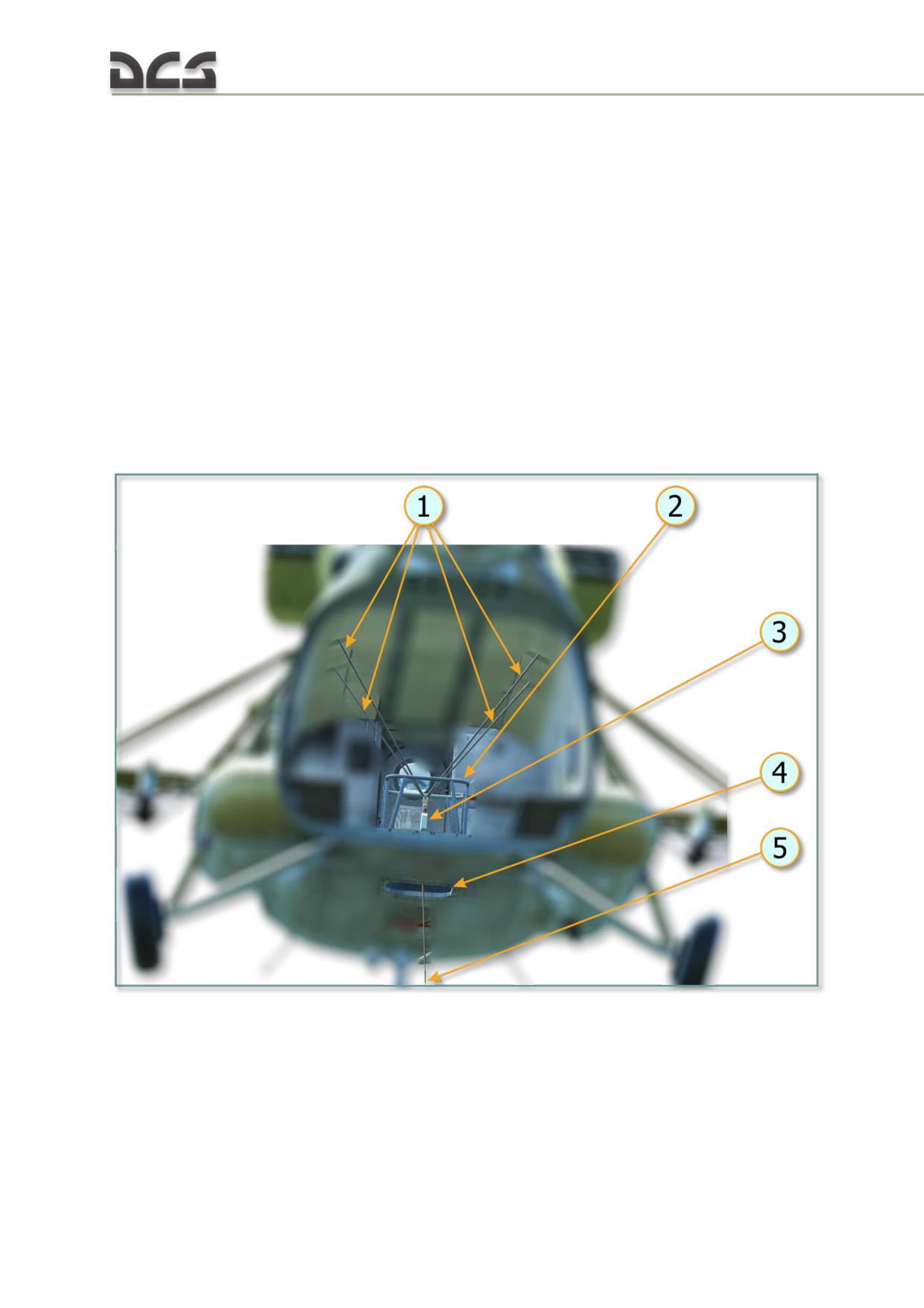
fuselage attach points;
release barrier;
pulley block and cable (not modelled);
extension cables for 5, 10, 15, 20, 30, 40, 50 и 65 m (up to 30m in
game);
cargo cable set (4х4m), also known as "spider" (any length is possible in
the game);
various additional details (swivel hook, master link of cargo cable set), are
not modelled.
The main load-bearing elements of the outer sling cable are four 16-mm cables. On
top of each cable there is a hinge by which this cable is attached to a special
fuselage attach point, located under helicopter’s ceiling (directly under the main rotor
transmission) on frames № 7 and 10. In the lower part all four cables are connected
with the scale of the DG-64M and then cable goes through the access hole. Sling
load equipment is shown on Fig. 7.42.
Fig. 7.42. Sling load equipment diagram
1. Four load-bearing cables
4. Access hole
2. Release barrier
5. Extension cables
3. DG-64M cargo hook
7.10.2. Cargo hook controls
The DG-64M cargo hook lock is controlled electrically:
212
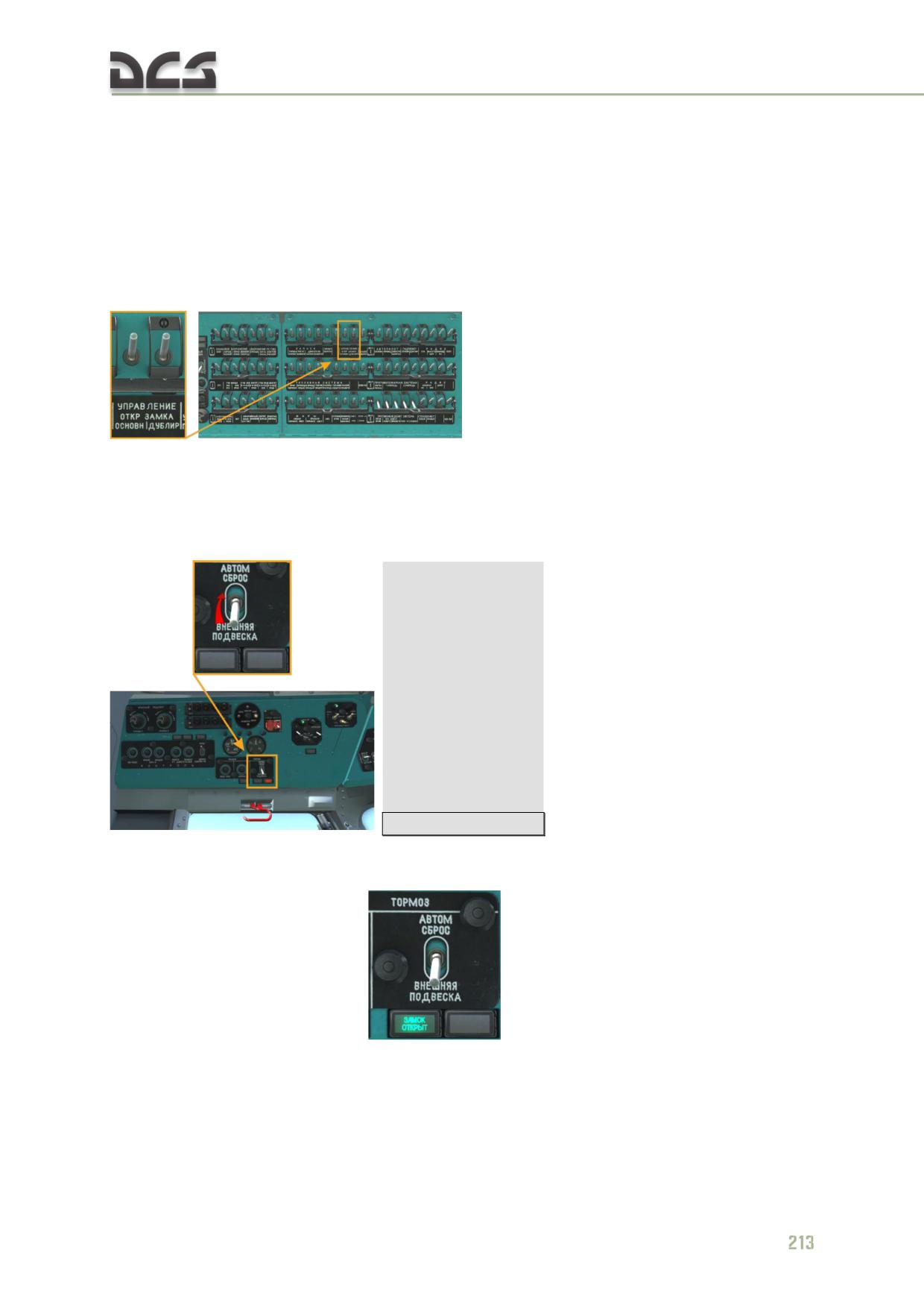
supply voltage is 27-29V;
minimum voltage required for hook opening is 20V.
Controling cargo hook lock means choosing the unhook method: either automatic
opening (or unhook) when cargo touches the ground or manually opening the lock in
flight (and cargo release).
To power up electrical circuits, controlling hook lock, pilot must enable the
"УПРАВЛЕНИЕ ОТКРЫТИЕМ ЗАМКА" "ОСНОВНОЕ", "ДУБЛИР" (CARGO HOOK MAIN
AUX)
on
the
right
overhead
circuit
breaker
panel:
Automatic opening
Automatic cargo unhook is activated before landing when cargo is already hooked.
To do that, one must enable the ВНЕШНЯЯ ПОДВЕСКА АВТОМ СБРОС (EXTERNAL
LOAD AUTO RELEASE) switch (UP), located on the left side panel:
[RCtrl + RShift + K]
When cargo touches ground and load on lock lever reduces to less than 25 kg, hook
opens and cargo remains on the ground. When lock is opened, the ЗАМОК ОТКРЫТ
(HOOK OPEN) light panel is on
Manual cargo release
Cargo hook can be opened during flight (cargo release). Two procedures are used
for that: normal (tactical) release and emergency cargo release, if emergency
situation occurs during the flight.
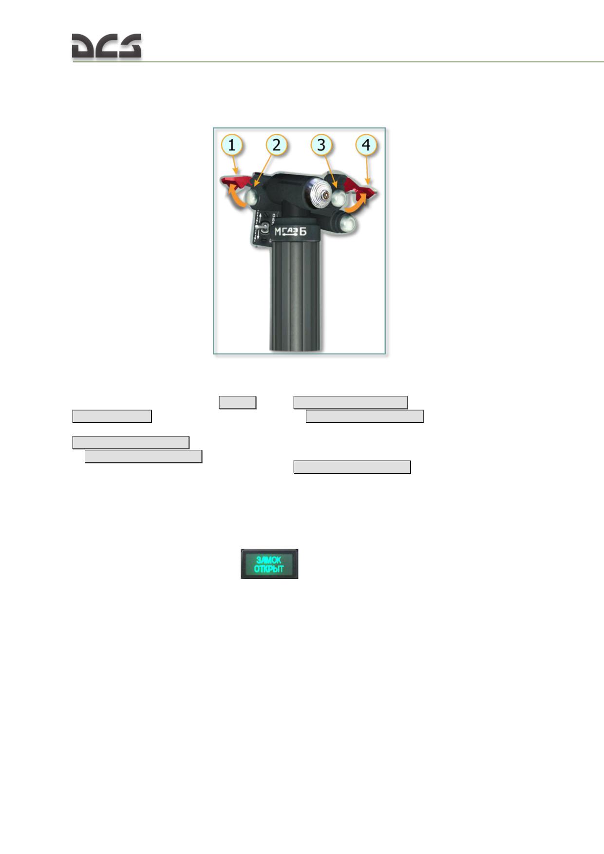
To open hook lock with help of electromagnetic trigger, pilot has to press tactical
cargo release button or emergency cargo release button. Both buttons are located on
collective, Fig. 7.43.
Fig. 7.43. Cargo release buttons on the collective
1. Safety cover of the АВАР СБРОС
3. Tactical release button
(EMERGENCY RELEASE) button
[RCtrl +
[RCtrl + Rshift + Ralt +L]
Rshift + Ralt + R]
or
[RCtrl + Rshift + Ralt + Q]
(only if safety
2. Emetgency release button
cover is opened)
[RCtrl + Rshift + Ralt + P]
4. Safety cover of the ТАКТ СБРОС ГРУЗА
or
[RCtrl + Rshift + Ralt + A]
(only if safety
(TACTICAL CARGO RELEASE) button
[RCtrl + Rshift + Ralt + T]
cover is opened)
There is no any difference for player in tactical or emergency cargo release during
flight, result is completely the same. The only difference between tactical and
emergency release is that release signal goes via different electrical circuits to open
the DG-64 cargo hook. In both cases, when hook is opened, the ЗАМОК ОТКРЫТ
(HOOK OPEN) light panel is on
Cargo hook is closed manually (in this game it closes automatically, if cargo is
selected with help of radio menu and player hovers over the cargo for some amount
of time, see here).
Sling load operation (selection of the cargo, attachment and release) is described
here.
7.11. АП-34Б (AP-34B) autopilot system
7.11.1. General description
The AP-34B four-channel electrical-hydraulical autopilot system is designed to
stabilize the helicopter in roll, pitch, heading, altitude, and airspeed. The autopilot is
214
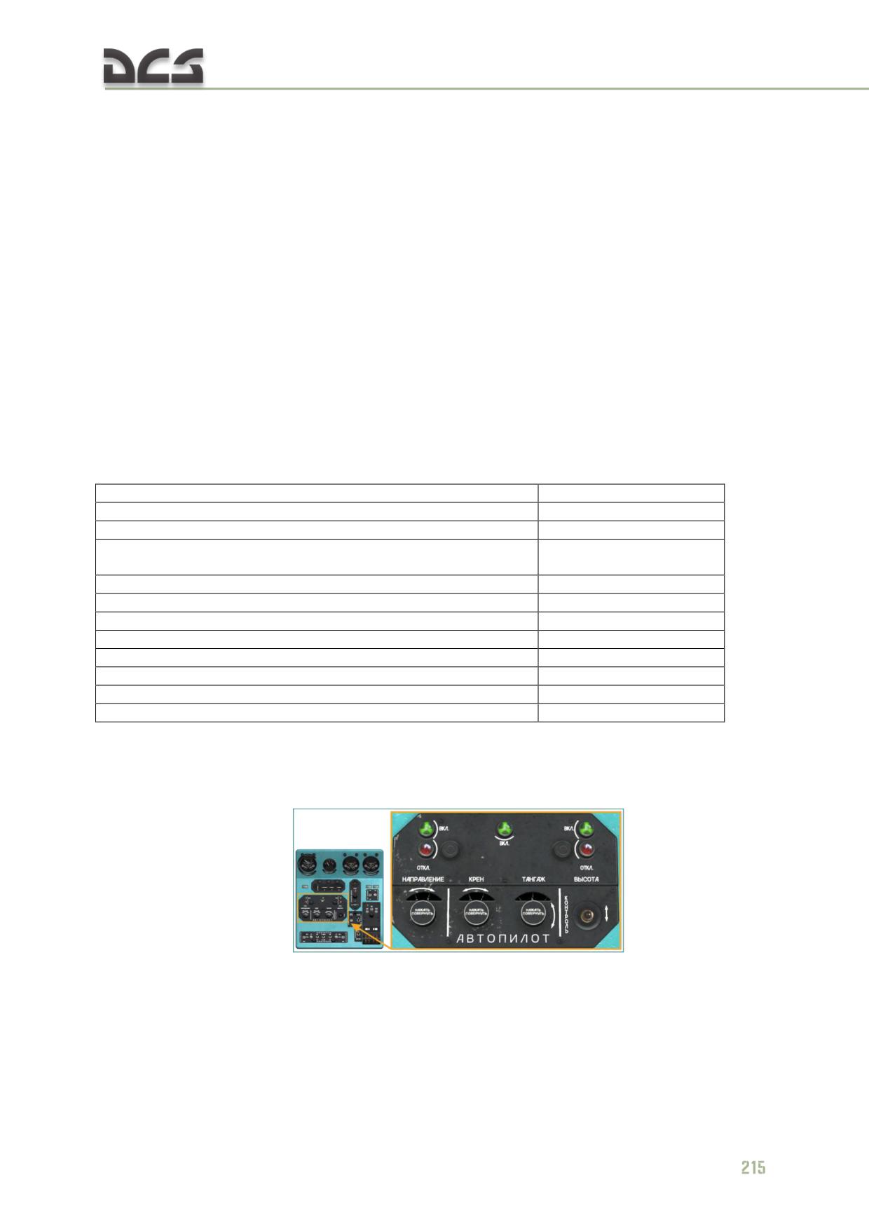
a system, receiving information about changes in angular positions of the helicopter,
barometric altitude and instrumental airspeed. It has four independent autopilot
channels, controlling corresponding helicopter’s controls:
yaw channel - tail rotor pitch;
roll channel - swashplate in lateral direction;
pitch channel- swashplate in longitudinal direction;
altitude channel - main rotor pitch;
When the altitude channel is engaged, the pitch channel receives correction signals
from the КЗСП (KZSP) airspeed correction unit to stabilize the airspeed.
The four autopilot channels (roll, pitch, yaw, altitude) provide:
stabilization of helicopter’s position in three axes (longitudinal, lateral,
vertical);
stabilization of altitude, during sustained level flight and hover;
stabilization of indicated airspeed.
AP-34B autopilot system specifications:
Supply voltage, DC
+28.5 V
Supply voltage, AC
~36 V (3Ph), 400 Hz
Time to readiness
under 2 min
Controls travel range in percents of full travel range, given to the
20%
autopilot:
Autopilot stability in calm atmosphere conditions:
yaw channel
±1°
roll channel
±0,5°
pitch channel
±0,5°
altitude
±10 m
airspeed
±10 km/h
Max altitude
10000 m
Weight
under 25 kg
7.11.2. Autopilot system’s unit
The AP-34B autopilot system includes the following units:
control panel
;
control unit, it is needed for transforming, accumulating and amplifying of
the control signals (fully modeled);
yaw, roll and pitch angular velocity sensors (fully modeled);
amplifiers unit (fully modeled);
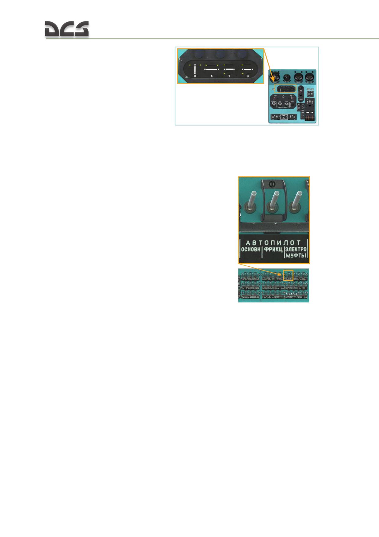
ИН-4 (IN-4) zero indicator
;
three compensation sensor (in each channel, fully modeled);
КВ-11 (KV-11) altitude corrector (fully modeled).
The АП-34Б (AP-34B) autopilot and control system mechanisms are powered by 27V
DC from the onboard battery and rectifier buses bus via the АВТОПИЛОТ-ОСНОВН.
(AUTOPILOT-MAIN), АВТОПИЛОТ-ФРИКЦ. (AUTOPILOT-FRICT) and АВТОПИЛОТ-
ЭЛЕКТРОМУФТЫ (AUTOPILOT-SOLENOID CLUTCHES)
circuit
breakers. All circuit breakers are located on the right circuit breaker console.
Additionally, system is powered by the 36 VAC 400 Hz from 36 V three-phase
generator buses.
7.11.3. Autopilot controls and indicators
Control panel
The autopilot control panel is located on the center console and provide the following
functions:
zeroing of autopilot control input prior to engaging the autopilot;
individual engagement/disengagement of autopilot channels;
entering of small corrections (±10%) using the centering knobs for pitch,
roll, and yaw channels;
testing of the altitude channel using the "КОНТРОЛЬ" (TEST) switch.
216
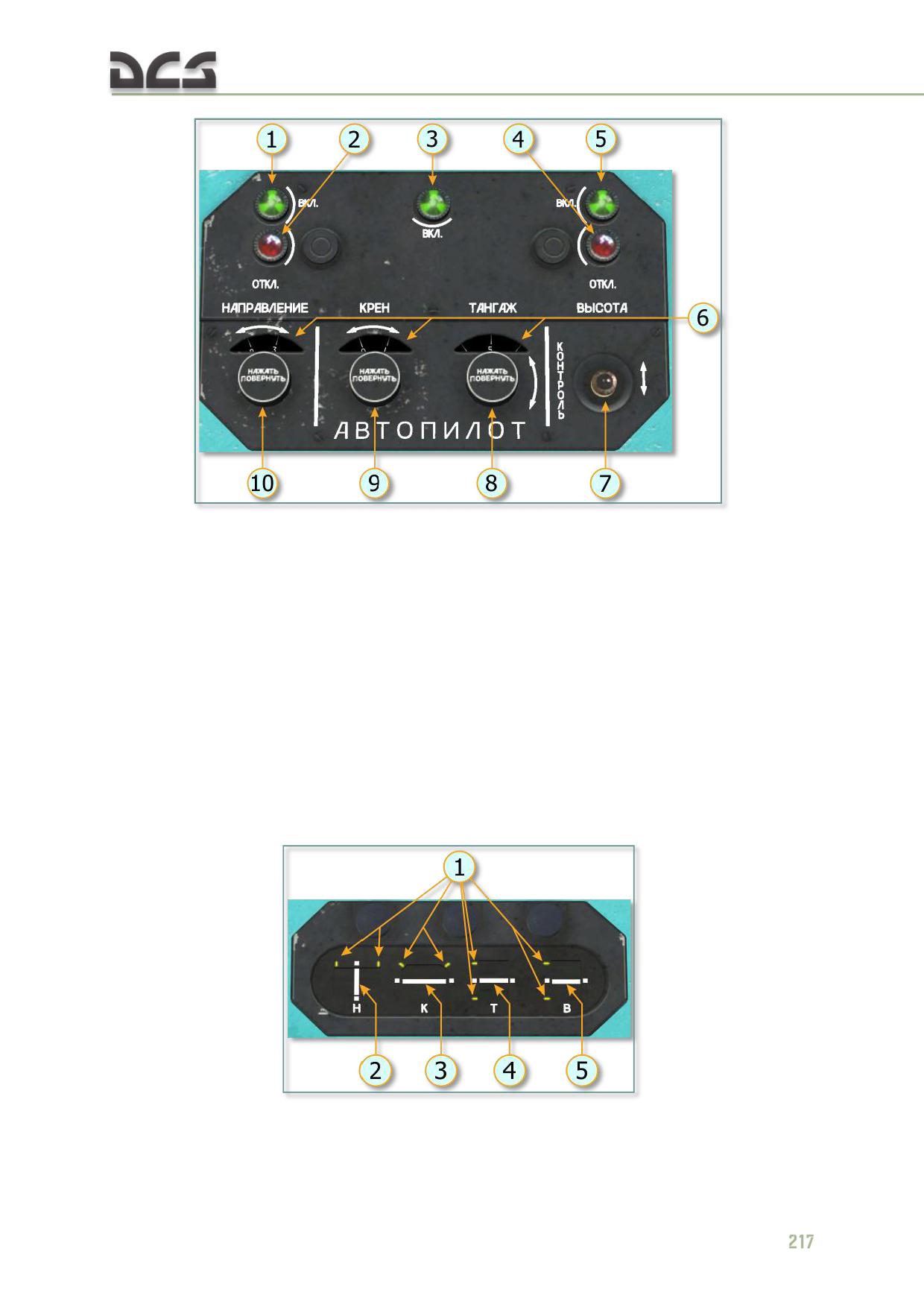
Fig. 7.44. Autopilot control panel
1. Lamp-button, enabling yaw channel
6. Rotating scales, indicating mismatch
2. Lamp-button, disabling yaw channel
between signals from yaw, roll and pitch
3. Lamp-button, enabling pitch and roll
sensors and actual controls position
channels
(1 mark corresponds to 1°)
4. Lamp-button, disabling altitude channel
7. КОНТРОЛЬ (CONTROL) button for checking
5. Lamp-button, enabling altitude channel
the altitude channel
8. Pitch channel centering knob
9. Roll channel centering knob
10. Yaw channel centering knob
ИН-4 (IN-4) zero indicator
The ИН-4 (IN-4) zero indicator unit shows the relative displacement of the flight
control servo spindle for each autopilot channel. It is located on the center console.
Fig. 7.45. ИН-4 (IN-4) zero indicator
1. Maximum deflection marks
4. Pitch channel indicator
2. Yaw channel indicator
5. Altitude channel indicator
3. Roll channel indicator
In other words, these indicators show center position of the control range, given to
the autopilot, relative to the helicopter controls such as pedals, collective or cyclic.
See below for explanations.
7.11.4.
Equipment interacting with the autopilot system
The GMK-1A gyro compass system provides signals to the autopilot
control panel to stabilize a given heading of the helicopter. Besides that,
this system gives signal to the control panel to engage
alignment/matching mode for the yaw channel, when course set mode
and course system check are enabled. This functionality is enabled, when
the НАПРАВЛЕНИЕ (YAW) channel is engaged.
AGB-3K ADI of the co-pilot is a roll and pitch sensor for the autopilot
system. It is used when the ROLL-PITCH channel is engaged.
The КЗСП (KZSP) airspeed correction unit is designed to provide an
electrical signal, proportional to the deviation of the actual speed from the
required one. The КЗСП (KZSP) affects pitch channel. It is used, when the
altitude channel is engaged.
The БСГ (BSG) ready signal unit operates together with the КЗСП (KZSP)
and provides ready signal, when КЗСП (KZSP) correction calculation
system is operational.
Combined KAU-30B control units (control actuator) and RA-60B steering
unit (control actuator) are executive units for both helicopter and
autopilot. They affect helicopter’s controls (swashplate of main rotor and
pitch control of tail rotor). Four steering units are installed in lateral and
longitudinal channels, collective channel and pedals channel. These
steering units have built-in feedback sensors, with help of which autopilot
receive feedback, see below.
Electromagnetic valves (GA-192), using signals from the autopilot, engage
steering units in autopilot mode (details described below).
Two ВЫКЛ. АП (AUTOPILOT OFF) buttons are installed on cyclics
[LWin
+ LShift + A]
Two buttons disengaging altitude channel, installed on the collectives
(their press is emulated when position of collective has been changed or
collective control buttons have been pressed -
[Num - ]
or
[Num +]
).
Four small-sized switches on the pedals. When pilot puts feets on the
pedals, these switches trigger and alignment mode engages for the yaw
channel.
Small-sized switch, located on mechanical rocker of the SPUU-52 tail rotor
pitch limit system, which is used to engage alignment mode for yaw
channel, when mechanical rod in pedal channel is close to the mechanical
stop, position of which is defined by the SPUU-52 system (i.e. yaw
channel disengages when mechanical stop is reached).
Time relay with
0.5s delay, included in yaw channel, to prevent
oscilations, when autopilot switches to alignment mode.
218
Autopilot’s distribution box (not modelled).
Due to fact that the AP-34B autopilot operates together with the KAU-30B and RA-
60A electro-hydraulical executive units (control actuators), controls of the helicopter
can be controlled by the pilot, using normal helicopter controls (cyclic and collective)
and by the autopilot simultaneously (so called combined mode, when pilot can
overrule autopilot at any time while autopilot is engaged). In this mode, autopilot
affect small cylinder of the steering unit, which is, in its way, an adjustable rod,
included into the control system. Due to that, resulting movement of the controls is a
sum of pilot’s and autopilot’s control inputs. Movements of the executive steering
units, due to signals from the autopilot, are not transferred back to cyclic and
collective.
Besides that, the autopilot can operate in the automatic helicopter stabilization mode
(when all four channels are engaged). Peculiarities in operation of the hydraulic units
in cases of autopilot and manual control are described below.
When the altitude channel is engaged, the pitch channel receives correction signals
from the КЗСП (KZSP) airspeed correction unit.
Autopilot roll, pitch, and altitude correction signals are limited to a maximum of 20%
of control travel for flight safety in the event of false signals or system failure. In
addition, the pilot may intervene at any time while the autopilot is engaged to make
manual corrections by operating the flight controls.
7.11.5. Use of autopilot in different flight phases
The autopilot system is engaged for all normal flight operations. The pitch and roll
channel is normally engaged throughout the flight from takeoff to landing. Yaw and
altitude channels are used rarely.
The autopilot is engaged before takeoff, by pressing lamp-buttons, corresponding to
the required channels
. The altitude channel can not
be engaged without engaging “ROLL-PITCH” channel.
When performing vertical takeoff, one must enable “ROLL-PITCH” channel
(pilots, operating Mi-8 in Russian Federation, normally do not engage “YAW”
channel before takeoff).
When performing rolling takeoff, engage only “ROLL-PITCH” channel. Engaging
must be monitored with help of lamp-buttons, which should be green for engaged
channels.
When in hover, the autopilot stabilizes the helicopter in pitch and roll, as well as
heading when the pedals are released (feet off the pedals). Autopilot functionality in
hover mode can be verified by checking the zero indicator unit for fluctuations in the
"К" (roll channel) "Т" (pitch channel) "Н" (yaw channel) servo displacement indicator
needles around neutral positions.
In sustained flight conditions such as level flight, climb or descent with flight
controls released by the pilots, the autopilot will stabilize the helicopter attitude while
slowly decreasing airspeed, because the system is maintaining a pitch angle and not
airspeed (up to 150 km/h).
Piloting the helicopter with help of autopilot without moving controls
To adjust a helicopter heading, within ±5° range during sustained level flight, while
autopilot is engaged, one must rotate the centering knob on the autopilot control
panel clockwise or counterclockwise
Complete rotation of this knob
results in heading change of 10°. There are ten ticks on the scale, each tick
corresponds to 1° . In a similar way, the roll and pitch can be adjusted.
The altitude channel can be engaged after establishing level flight at an altitude of
not less than 50 m. Altitude channel operation can be verified by fluctuations of the
"В" (altitude channel) servo displacement indicator needle on the zero indicator unit,
changing of the main rotor collective pitch angle on the UP-21-15 gauge, and vertical
displacement of the helicopter as the autopilot system maintains altitude in turbulent
air.
Landing approach, braking, and landing are normally performed with the autopilot
channels “ROLL” and “PITCH” engaged. After landing, the autopilot system is
disengaged with the "ВЫКЛ. АП" (Autopilot OFF) button, located on both cyclics
7.11.6. Explanations of the AP-34B peculiarities and key commands
Combined operation of hydraulic boosters and the AP-34B
autopilot in case of manual control
In case of automatic helicopter stabilization, the actuating rods of the KAU-30B combined hydraulic
boosters can move themselves within 20% of their full travel range, wherein control sticks (cyclics) do
not move and are hold in the same fixed positions by the spring load mechanism. Collectives are hold
by the friction mechanism.
Limitation of 20% (by design of steering units/ control actuators) of full travel range of is needed to
provide flight safety in case of autopilot failure, because the most of the failures are accompanied with
appearance of an one-way signal on the autopilot output and, as a result, fast reaction of the actuator
units.
220
At the same time, this limited operating range of actuator units using autopilot signals is sufficient for
compensation of real-life distrubances, affecting helicopter and for stabilization of angular positions of
the helicopter.
The pilot may intervene at any time while the autopilot is engaged. For this purpose are centering
knobs for pitch, roll and yaw channels, full rotation of which corresponds to 10° change. There are ten
ticks on the scale, each tick corresponds to 1° .
By rotating correspondinig centering knob clockwise or counterclockwise, pilot force the helicopter to
turn. When pilot intervene roll or pitch, it is necessary to remove impact of signals from angular and
angular velocity sensors on hydraulic boosters of roll and pitch channels. For this purpose the
compensation sensors, kinematically connected with lateral and longitudinal controls, which provide
signals, equal to ones received from attitude indicator, but with opposite sign, are installed. In other
words, when pilot moves cyclic, the reference value of roll and pitch (which autopilot will maintain) is
constantly being updated.
In this way pilot controls helicopter’s roll and pitch, without disengaging autopilot, which is constantly
trying to maintain helicopter’s position, given by the pilot. For the pilot, to control yaw, on the pedals
are triggers and microswitches, which, when pressed, enable alignment mode for yaw channel. When
maneuver is finished and pedals are released, the autopilot for yaw channel engages automatically.
Game peculiarities, when pedals are used and "НАПРАВЛЕНИЕ"
(YAW) channel is engaged
To control yaw in the Mi-8MTV2, the RA-60A steering unit is used. Unlike the KAU-
30B, it has a special mechanism, allowing autopilot to move pedals, if limited travel
range of 20% is not sufficient for maintaining given direction.
If, for example, yaw channel is engaged and player during vertical ascend is not
compensating reactive moment of the main rotor with pedals, then after using 20%
of limited travel range, the RA-60A will be moving the right pedal forward without
any actions from player. Player pedals will remain in the same position. To align
position of player pedals with position of virtual pedals in Mi-8 model, perform the
following actions:
return gaming pedals to a neutral position (if pedals have springs - simply
remove feets from the pedals);
reset trimmer
[LCtrl + T]
After this procedure the pedals in the model return to a neutral position and they will
be aligned with gaming pedals.
NOTE. Take into account that this procedure returns cyclic into neutral position, as well.
Trimmer features when autopilot is engaged
As in real life, in our model interaction between trimmer and autopilot in the Mi-8 is different from the
one, implemented in the Ka-50. In the Mi-8 depression and holding of the trimmer button do not
engage alignment mode of the autopilot, as it is done in the Ka-50. I.e. trimmer as object is not
interacting with autopilot at all.
Autopilot controls roll (pitch) within 20% of full cyclic travel range for this channel. The edge positions
on the IN-4 zero indicator (Fig. 7.45, 1) tell us that hydraulic boosters of roll or pitch (more precisely
the small cylinders of the steering unit) reached 20% of travel range, given for automatic stabilization
of roll and pitch angles. This appears as incrased sensitivity in helicopter reaction on small cyclic
movements to the side where limit was reached and creates certain discomfort for piloting.
The deviation of the center of the 20% zone, given to autopilot to stabilize helicopter, from current
position of the cyclic, can be estimated with help of IN-4 (Fig. 7.46, 2). If pilot, using trimmer, moved
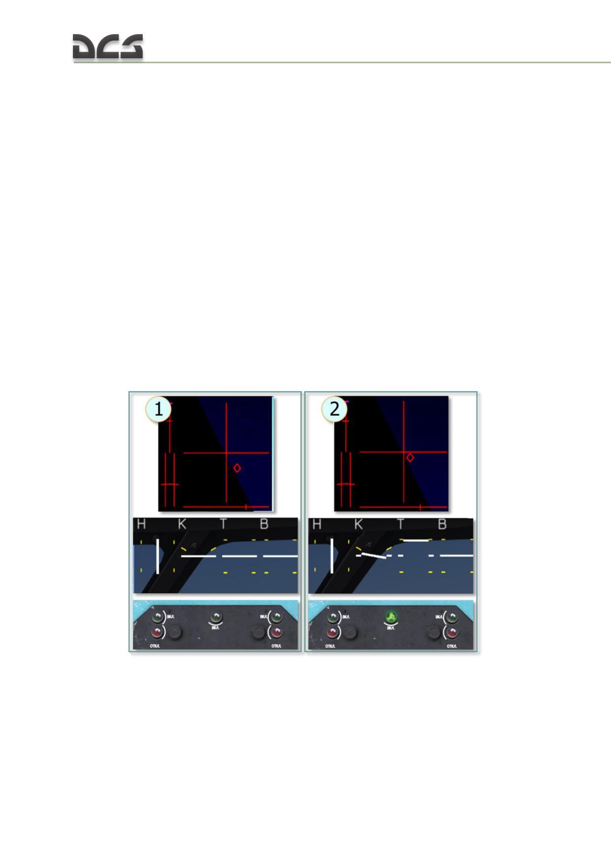
cyclic outside this zone (according to indications on the IN-4), then autopilot is not able to
“comfortably” stabilize roll (pitch) anymore, as before. Of course, pilot feels discomfort as well, even
when applied forces were removed from cyclic by the trimmer. In practice, it requires increased
amount of small cyclic corrections, needed for maintaining desired roll or pitch. To ease piloting, it is
necessary align the center of autopilot’s 20% of range with the current position of the cyclic. In other
words,“point” the autopilot to a new reference position. This can be done in the two following ways:
1. By Centering knobs on the AP-34B control panel. In real life, it is a crew chief, who
normally, by rotating these knobs, removes misalignment, by setting roll and pitch according to
horizontal marks. Pilot, during this process, must slowly move cyclic towards new position to maintain
sustained flight, i.e. moving away from the position where autopilot was engaged and then trimming
the cyclic once again.
2. By disabling autopilot and balance correction followed by the autopilot engagement.
The first approach is useful, because it gives an opportunity to smoothly remove misalignment, the
second allows to do it fast without involving other crew members.
To better understand mentioned above features, see below.
Positions of Cyclic and zero indicators on IN-4 during Hover and
Level fligh (Roll-Pitch channel)
Below, the positions of cyclic, depending on moment when the “ROLL-PITCH”
channel was enabled, are shown for hover and level flight.
HOVER
Fig. 7.46. Hover
1. Hover.
2. Hover.
AP-34B (Roll-Pitch channel) is OFF
AP-34B (Roll-Pitch channel) was turned ON while
on the ground, when Cyclic is in neutral position
222
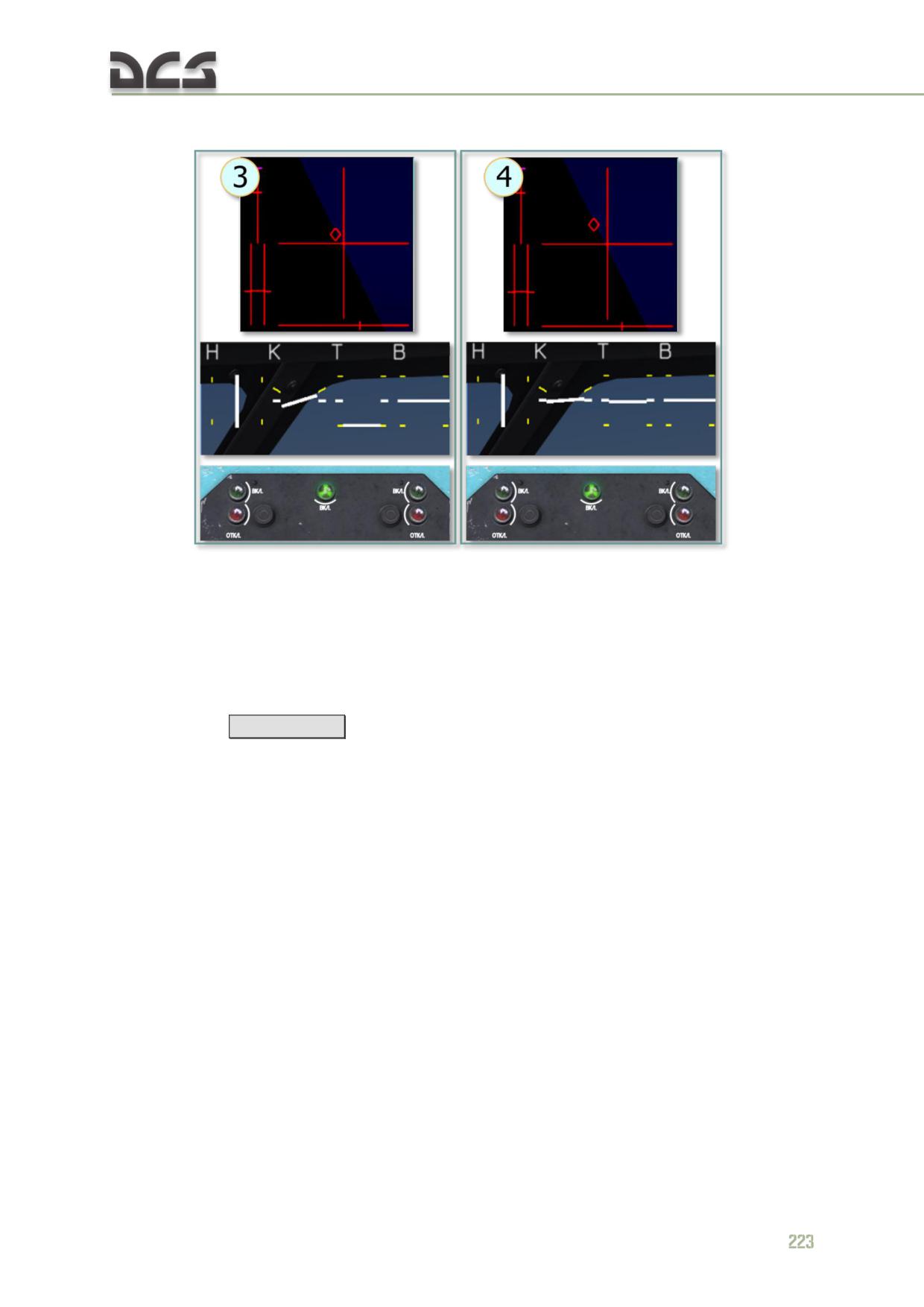
LEVEL FLIGHT
Fig. 7.47. Level Flight at 240 km/h
3. Speed 240 km/h.
4. Speed 240 km/h.
The AP-34B has been turned ON during hover
The AP-34B has been turned OFF during flight at
240 km/h and then ON again after helicopter was
balanced.
In the game, there is an opportunity to adjust “ROLL-PITCH” with help of AI crew
chief. Auto adjustment can be performed by a command from player (key
kombination)
[RAlt
+ A]
or automatically, if in the Mi-8MTV2 (see 14.8.1) the
“Autopilot Adjustment” checkbox is set, Fig. 7.48.
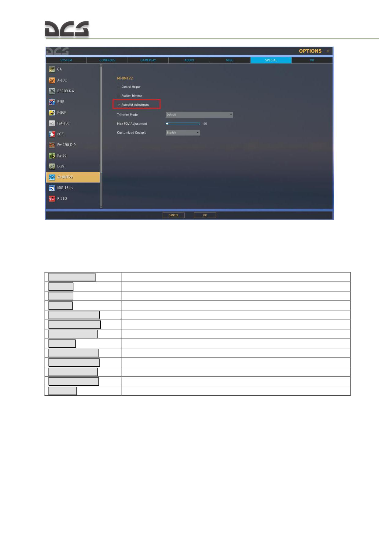
Fig. 7.48. The "Autopilot Ajustment" checkbox in special settings
When AI crew chief receives a command from the player to adjust the autopilot it
will “report” about actions taken.
AP-34B Key Commands
LAlt + LWin + A
Autopilot Altitude Channel OFF Button
LAlt + A
Autopilot Altitude Channel ON Button
LAlt + V
Autopilot Altitude Control Switch - Down
LAlt + F
Autopilot Altitude Control Switch - Up
LShift + LWin + S
Autopilot Heading Adjustment Knob - CCW/Left
LShift + LWin + D
Autopilot Heading Adjustment Knob - CW/Right
LCtrl + LWin + A
Autopilot Heading Channel OFF Button
LCtrl + A
Autopilot Heading Channel ON Button
LCtrl + LShift + S
Autopilot Pitch Adjustment Knob - CCW/Left
LCtrl + LShift + D
Autopilot Pitch Adjustment Knob - CW/Right
LWin + RCtrl + S
Autopilot Roll Adjustment Knob - CCW/Left
LWin + RCtrl + D
Autopilot Roll Adjustment Knob - CW/Right
LWin + A
Autopilot Roll/Pitch Channel ON Button
7.12. Exhaust IR suppression devices
Installs exhaust IR suppression devices (Fig. 7.49). It decreases engines’ IR
signature by approximately two times. This reduces lock on range for IR SAMs and
increases probability of successful flight through SAM protected areas.
224
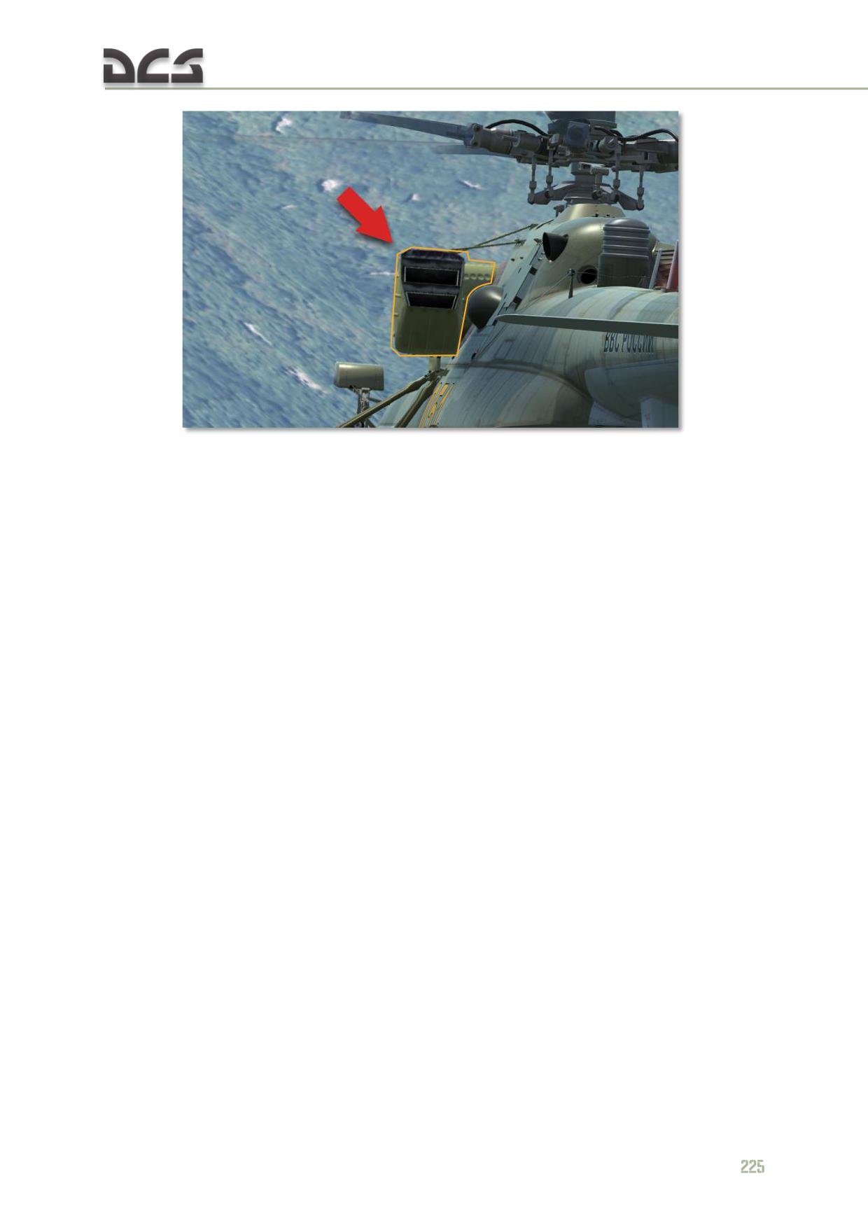
Fig. 7.49. Exhaust IR suppression devices
N O T E . Installation of the IR suppression devices requires, according to flight manual, to reduce
calculated takeoff weight by 300 kg. On the charts it is equal to increasing ambient temperature by
+3°С. Besides that, empty helicopter weight is increased by 160 kg.
OPERATING LIMITS
8
AND RESTRICTIONS
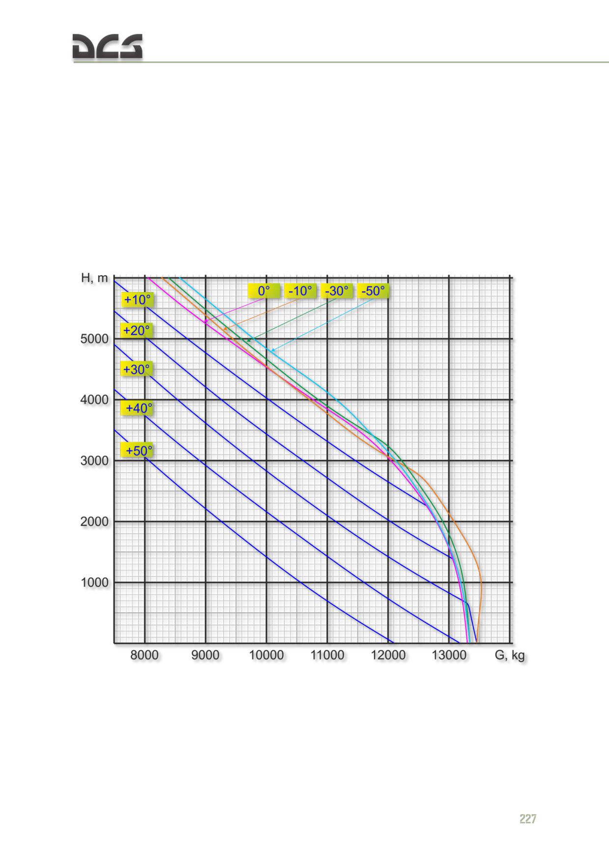
DIGITAL COMBAT SIMULATOR Mi-8МТV2
8. OPERATING LIMITS AND RESTRICTIONS
8.1. Calculating maximum takeoff weight
Maximum takeoff weight for out of ground effect vertical takeoff (landing) (OGE
maximum hover weight) is displayed by Fig. 8.1. Maximum takeoff weight for in
ground effect vertical takeoff (landing) (IGE maximum hover weight) is displayed by
Fig. 8.2.
The maximum hover weight charts display maximum takeoff weight in relation to the
pressure altitude of the landing field and free air temperature (FAT) assuming calm
winds, 93% main rotor RPM, disengaged PZU Air Inlet Particle Separator System
(PSS), disengaged anti-ice systems.
Fig. 8.1. OGE maximum hover weight chart (hover altitude 20 m).
PZU and anti-icing disabled
N O T E . If EGS installed, reduce maximum weight indicated in chart by 300 kg.
With PZU (PSS) turned on, reduce maximum takeoff weight indicated in chart by 200
kg. With engine and rotor anti-ice systems turned on, reduce maximum takeoff
weight indicated in chart by 1000 kg.
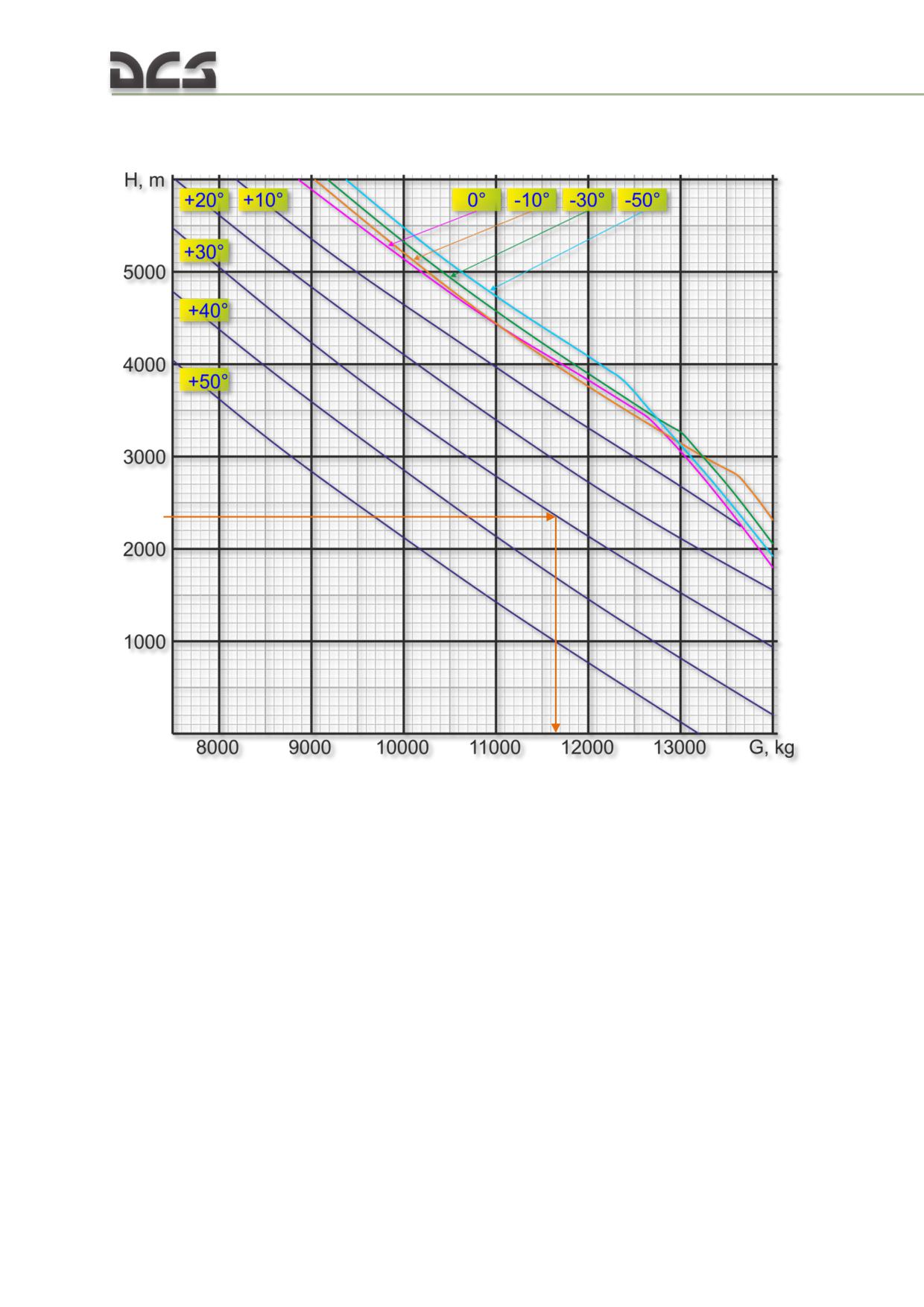
When Exhaust IR suppression devices (7.12) are fitted reduce maximum takeoff
weight indicated in chart by 300 kg.
Fig. 8.2. IGE maximum hover weight chart (hover altitude 3 m).
PZU and anti-icing disabled.
Any headwind increases maximum takeoff weight: +200 kg at 5 m/s; +1200 kg at
10 m/s.
Crosswind up to 5 m/s reduces performance by affecting the tail rotor and increasing
engine power requirements. Reduce maximum takeoff weight by 200 kg in the
presence of a crosswind of up to 5 m/s. At greater crosswind speeds, translational lift
effects become more dominant.
Performance reduction in tailwind conditions (blowback of hot exhaust gases into the
exhaust system) is not modeled in the simulation.
When calculating wind corrections for maximum hover weight, consider that wind
speed and direction may vary during takeoff/landing. Assume the lowest maximum
hover weight corresponding with possible wind variance.
If wind conditions cannot be determined, assume poor hover conditions of 4-6 m/s
tailwind.
228
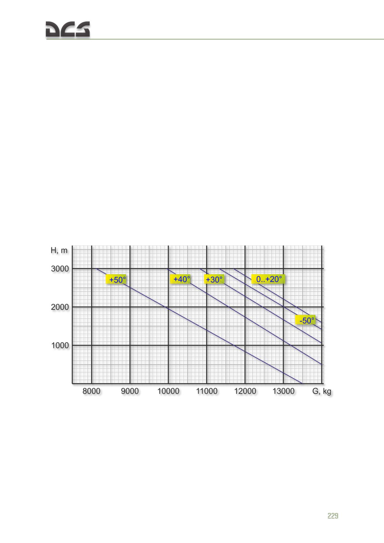
EXAMPLE:
Fig. 8.2 includes a solution (orange arrows) to the following example problem: determine the
maximum hover weight for vertical takeoff in ground effect from an airfield located at an altitude of
2,300 m and +30°C FAT.
SOLUTION:
Using the IGE maximum hover weight chart Fig. 8.2, enter the graph from the left at the point of the
desired pressure altitude of 2,300 m. Draw a line horizontally to intersect the desired temperature of
+30°C. From the intersection point, draw a vertical line down to find the maximum hover weight
value, in this case 11,680 kg.
To determine the maximum takeoff weight for a vertical takeoff out of ground effect, perform the
same process using the OGE maximum hover weight chart Fig. 8.1.
MAXIMUM TAKEOFF WEIGHT FOR A RUNNING TAKEOFF:
To determine the maximum takeoff weight for a running takeoff, utilize the IGE
maximum hover weight chart Fig. 8.2, but add an additional 500 kg to the solution.
Prior to performing a running takeoff, execute a test hover to an altitude of no less
than 1 m to verify correct maximum weight calculation.
MAXIMUM TAKEOFF WEIGHT FOR A NOSE WHEEL RUNNING TAKEOFF:
Use nose wheel running takeoff maximum takeoff weight chart Fig. 8.3 to determine
the maximum takeoff weight for a nose wheel running takeoff.
Fig. 8.3. Nose wheel running takeoff maximum takeoff weight chart
Execute a test hover to verify correct maximum weight calculation prior to
performing a nose wheel running takeoff. The takeoff can be performed if the
helicopter is able to lift off the ground during the test hover.
In all cases, the maximum takeoff weight should never exceed the helicopter
maximum gross weight of 13,000 kg.
The calculate fuel and cargo weight limitations, individual helicopter component
weights are provided in the Table 8.1:

Table 8.1
Weight, included in
simulation model (as
No
Mi-8MTV2
May be
"equipped empty
weight ")
1
Empty helicopter weight
7200
2
Cabin ladder
7.3
7.3
3
Safe
4.5
Not modeled
4
Auxiliary fuel tank
70
Not modeled
5
Troop seats (30)
58.7
58.7
6
Cargo ramps
31.6
Not modeled
7
ЛПГ-150м (LPG-150M) hoist
33.5
33.5
8
Mounts for assault rifle
19.8
19.8
9
Waste equipment
93.6
Not modeled
10
Assault ropes
6
Not modeled
11
Unusable fuel
20
20
12
Main fuel 0.775 kg/L
counted in the mission
- service tank
322
editor
counted in the mission
- main tanks
1608
editor
- auxiliary tanks
1388
Not modeled
13
Armor plating
419
419
- cockpit
332
- cargo cabin
33
- hydraulics compartment
54
14
Weapons stations racks
401
401
Nose PKT 7.62-mm machine gun w/
15
38.8
Not modeled
ammo
Tail PKT 7.62-mm machine gun
counted in the mission
16
26.9
w/ammo (3 box at 250 cartridges)
editor
Door Machine gun 'KORD" 12.7-mm with
mounting device and on-board
counted in the mission
17
138
ammunition supplies (12 box at 50
editor
cartridges)
UV-26 (self-defense EW system) with
18
26.3
26.3
128 flares
counted in the mission
19
B8-V20A launchers w/t ammo
100
editor
counted in the mission
20
Rockets (20 x 80-mm S-8OM)
242
editor
GUV-1 (12.7-mm +7.62-mm machine
counted in the mission
21
452
gun)
editor
counted in the mission
22
GUV-1 (30-mm grenades)
274
editor
counted in the mission
23
UPK-23-250 (23-mm mashin gun)
230
editor
24
Minelaying container (empty)
70
Not modeled
25
Crew O2 equipment
19.3
Not modeled
26
Rope ladder
19.7
Not modeled
27
PKV sight
2.5
2.5
28
OPB-1r sight
8.2
Not modeled
29
Junction box of weapon with Bombing
15.9
15.9
230

weapon Control Panel
30
Rescue eqiupment:
216
Not modeled
- LPG-300 hoist
60
- hoist installation
95.5
- Junction box with fixing system
15.6
- spot light
20.5
- rescue basket
30
- boat-hook
0.9
- hand spot light (2)
2
- rescue belt (2)
4
- crew cheif belt
1.8
- rubber mat
6.6
- rescue seat
9
- other
5.4
31
External sling system:
160.5
160.5
- keylock DG-64M
21.3
- Safeguard (skirt) of bottom
9.3
flap
- main ropes (4x1.11m)
10
Releasable components:
119.9
- sling cable type 1.7m
3.15
- sling cable type 5m
7.3
- sling cable type 10m (2)
27.3
- sling cable type 20m (2)
52.5
- lower strap (4x4m), or cargo
24
hook
- minor components
5.6
32
Rotor blade mooring equipment
43.3
Not modeled
33
L166V1A (self-defense EW system)
25
Not equipted
Total equipment weight, kg
1164.5
34
Lubrication oil
71.7
71.7
35
Crew of three
270
270
Total helicopter weight (oil, crew) WITHOUT fuel
8706.2
and armament, kg
8.2. Calculating flight range, radius, and time
This section provides the required data for calculating flight navigation planning.
Flight range (radius) and flight time depend on fuel quantity and consumption rate,
which in turn depends on helicopter weight, payload (which affects aerodynamic
performance (in particular drag)), flight altitude and airspeed.
The effects of these factors on flight distance and time are examined below.
ALTITUDE. Helicopters are generally flown at low altitudes. However if long range
operations are required, flight at altitudes of 2000 - 3000 m result in approximately
15% greater range than low altitudes.
AIRSPEED. Greatest flight range is achieved at or near optimum cruise speed (±20
km/h)

CRUISE SPEED - optimum speed that provides greatest flight range (minimum fuel
consumption rate) is provided in Table 8.2.
Table 8.2
Helicopter weight 11 100 kg
Helicopter weight greater than
or less
11 100 kg
Altitude, m
Airspeed (km/h)
indicated
true
indicated
true
100
230
233
215
219
500
225
233
210
218
1000
220
233
205
218
2000
210
234
195
218
3000
195
230
160
190
4000
170
213
120
154
5000
120
163
6000
100
145
AERODYNAMIC FACTORS
When Exhaust IR suppression devices (7.12) are fitted, fuel consumption rates per
kilometer and per hour provided in Table 8.4 increase by 6%.
With armament fitted, fuel consumption rates are as indicated in Table 8.4.
ENGINE AIR BLEED FACTORS
With anti-icing and particle separator system engaged, fuel consumption rates
indicated in the tables below increase as follows:
engine anti-icing: 3%
main and tail rotor anti-icing: 2%
With the PZU particle separator system engaged, fuel consumption rates per hour
provided in Table 8.4 increase by 3%.
MINIMUM FUEL QUANTITY
To ensure flight safety, a minimum fuel quantity is provided, which equals 260 L for
the Mi-8MTV2.
GROUND RUNUP FUEL CONSUMPTION (GT3) includes:
fuel required for engine start, warm-up, and taxi: 30 kg/5 min (6 kg/min)
fuel required by the APU while powering the electrical systems prior to
engine start: 1.25 kg/min)
GROUND TARGET ATTACK RUNS consume 12 kg of fuel/min on the first run. With 4-minute
repeat attack runs, each is estimated to consume 50 kg, which is equivalent to a
reduction of flight radius by approximately 10 km.
232
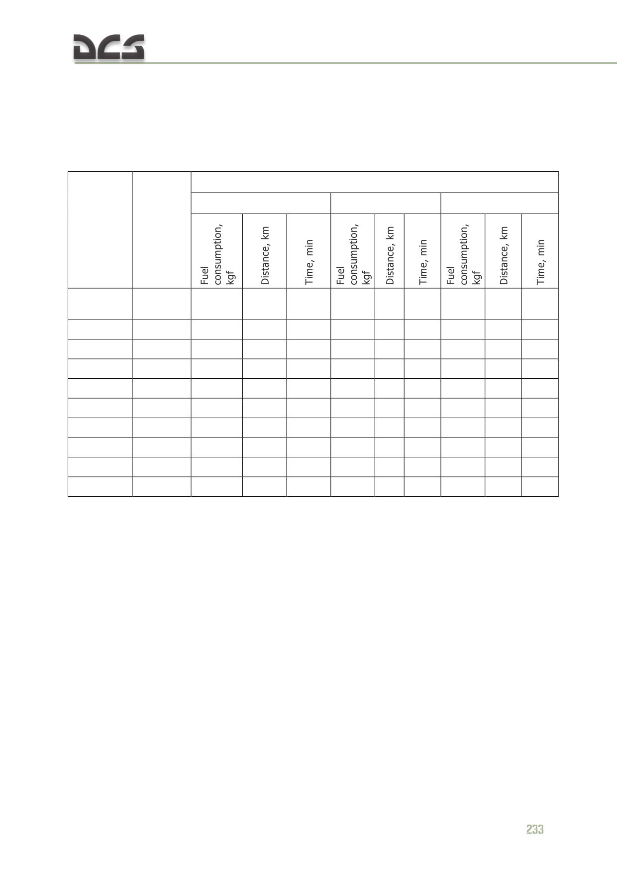
Fuel consumption rates required from takeoff to altitude are provided below in Table
8.3 (nominal engine power setting).
Fuel consumption, distance, and time required from takeoff to altitude:
Table 8.3
Helicopter weight, kg
11000
12000
13000
Indicated
Altitude, m
airspeed,
km/h
Takeoff
-
15
-
1
15
-
1
15
-
1
and climb
100
120
20
-
1.5
20
-
1.5
20
-
1.5
500
120
25
-
2
30
-
2
30
-
2
1000
120
35
4
2.5
40
5
3
40
5
3
2000
120
55
7
4
60
9
4.5
70
10
5.5
3000
110
75
10
6
85
13
7
100
15
8
4000
110
95
15
7.5
115
19
9
140
30
11.5
4800
100
-
-
-
-
-
-
215
40
18
5000
100
115
20
9.5
155
27
13
6000
90
170
30
15
*
*
-
-
-
-
FUEL CONSUMPTION RATES AT VARIOUS WEIGHT, ALTITUDES AND AIRSPEEDS FOR BOTH MAXIMUM
RANGE AND DURATION'S LEVEL FLIGHT, see Table 8.4
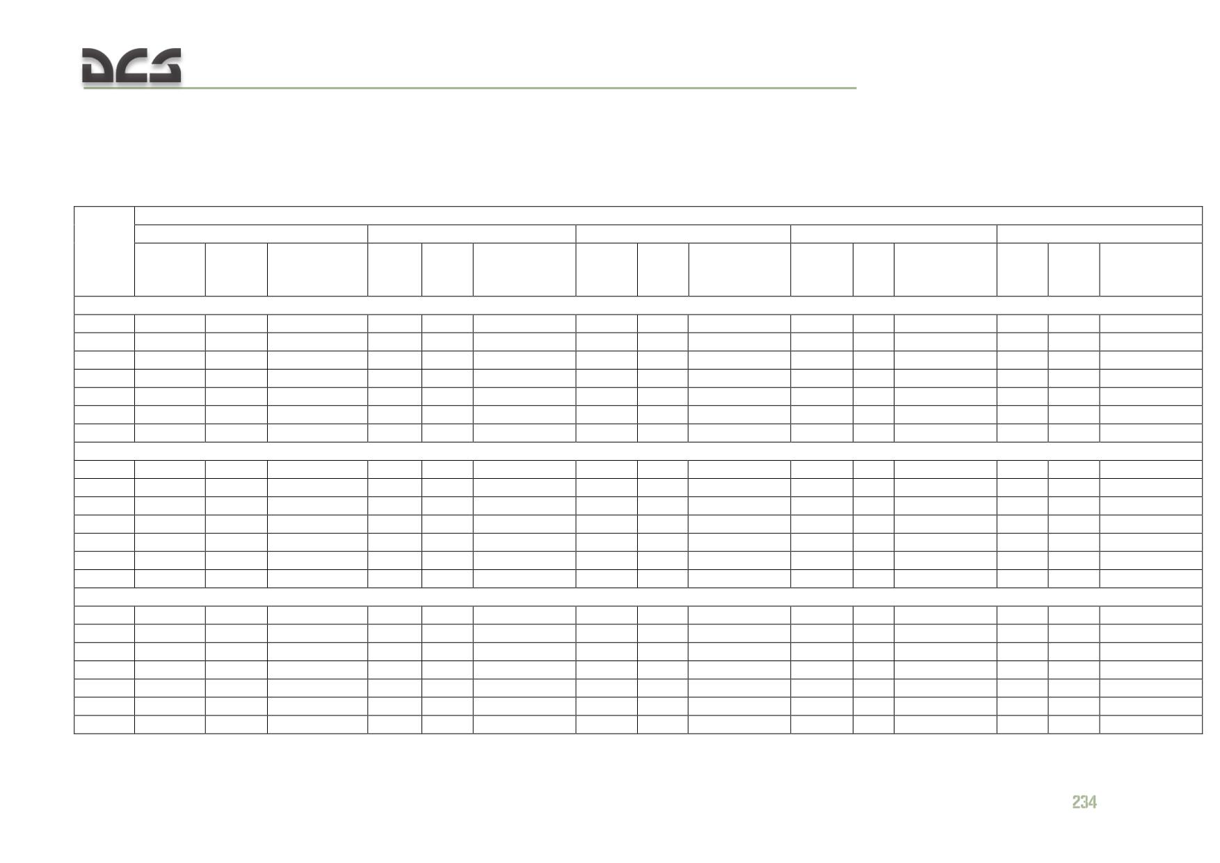
DIGITAL COMBAT SIMULATOR Mi-8МТV2
Per kilometer and per hour fuel consumption rates at various altitudes and airspeeds for maximum rage depending on helicopter
weight.
Main rotor RPM 95%
Table 8.4
Fuel consumption rate vs helicopter weight (kg)
9000
10 000
11 000
12 000
13 000
Н, m
Qmin кgf/hr/
q,
Q,
Q,
Qmin кgf/hr/
Q,
q,
Q,
q,
Q,
Qmin кgf/hr/
q,
q,
Qmin кgf/hr/
Qmin кgf/hr/
at Vind,
kgf/k
kgf/h
kgf/h
at Vind,
kgf/
kgf/k
kgf/h
kgf/km
kgf/hr
at Vind, km/h
kgf/km
kgf/km
at Vind, km/h
at Vind, km/h
km/h
m
r
r
km/h
hr
m
r
Transport configuration (w\o Weapons stations racks)
100
2.66
620
445 / 120
2.69
627
470 / 120
2.75
641
495 / 120
2.84
621
520 / 110
2.93
640
550/ 120
500
2.55
593
445 / 120
2.6
605
455 / 110
2.67
621
485 / 110
2.76
601
515 / 110
2.84
623
545 / 110
1000
2.44
569
425 / 120
2.49
580
450 / 120
2.57
599
475 / 120
2.66
587
505 / 120
2.77
614
540 / 120
2000
2.24
525
400 / 100
2.33
546
425 / 100
2.42
572
455 / 110
2.56
559
490 /130
2.72
592
530 / 120
3000
2.11
485
380 / 100
2.23
510
410 / 110
2.36
540
445 / 120
2.65
500
480 / 120
2.94
554
535 / 120
4000
2
426
370 / 100
2.14
455
400 / 110
2.36
502
445 / 120
3.23
487
495 / 120
3.85
575
580 / 110
5000
2.09
354
360 / 100
2.37
406
400 / 110
2.8
488
470 / 110
Combat configuration (with Weapons stations racks) without armament
100
2.75
643
445 / 100
2.81
660
475 / 100
2.87
676
500 / 115
2.95
651
530 / 120
3.03
673
555 / 120
500
2.67
630
435 / 110
2.73
646
460 / 110
2.79
663
490 / 110
2.85
640
515 / 110
2.94
660
545 / 115
1000
2.55
613
425 / 110
2.6
629
450 / 110
2.66
648
480 / 110
2.75
627
505 / 110
2.9
651
540 / 110
2000
2.34
570
400 / 100
2.42
586
425 / 100
2.53
610
460 / 100
2.63
599
500 / 115
2.81
638
540 / 115
3000
2.21
515
385 / 105
2.29
540
415 / 115
2.44
581
445 / 120
2.7
527
490 / 120
3
579
550 / 120
4000
2.07
447
370 / 120
2.23
477
405 / 110
2.5
523
450 / 115
3.46
522
525 / 100
4.17
596
630 / 100
5000
2.12
375
360 / 100
2.45
431
415 / 100
3.03
507
520 / 100
Combat configuration with armament
100
2.83
692
450 / 110
2.91
697
480 / 115
2.99
706
505 / 115
3.07
673
530 / 110
3.15
686
560 / 120
500
2.75
679
440 / 110
2.83
681
460 / 110
2.91
684
490 / 110
2.99
649
520 / 110
3.07
662
550 / 115
1000
2.66
645
430 / 110
2.75
650
455 / 110
2.82
657
480 / 100
2.9
624
510 / 110
2.99
642
545 / 120
2000
2.45
586
405 / 100
2.52
593
433 / 100
2.6
607
465 / 110
2.7
594
505 / 130
2.86
625
550 / 120
3000
2.26
522
385 / 100
2.36
536
415 / 100
2.48
559
450 / 120
2.75
537
495 / 120
3.13
617
560 / 110
4000
2.12
464
375 / 120
2.28
481
405 / 110
2.6
548
455 / 110
3.65
553
545 / 100
4.5
684
695 / 110
5000
2.15
376
365 / 105
2.61
445
425 / 100
3.6
553
595 / 100
q, kgf/km - fuel consumption in kg for 1 km; Q, kgf/hr - fuel consumption in kg per hour; Vind - indicated airspeed
DIGITAL COMBAT SIMULATOR Mi-8МТV2
FUEL CONSUMPTION, DISTANCE, AND TIME REQUIRED IN LANDING APPROACH
Table 8.5
Indicated
Fuel
Starting altitude, m
airspeed,
Descent rate, m/s
consumption,
Distance, km
km/h
kgf
Deceleration, hover,
-
15
1
and landing
100
120-130
2-4
20
-
500
140-150
5-6
25
5
1000
140-150
5-6
30
10
2000
140-150
5-6
45
20
3000
140-150
5-6
60
30
4000
120
3-4
90
40
5000
120
3-4
130
55
FUEL CONSUMPTION PER HOUR IN HOVER (KGF/HR) OUT OF GROUND EFFECT
Table 8.6
Fuel consumption per hour (kgf/hr) vs airfield altitude, m
Helicopter weight
0
500
1000
2000
3000
9000
700
660
640
630
610
10000
730
710
700
690
690
11000
790
770
770
760
-
12000
850
840
840
-
-
13000
920
920
-
-
-
To calculate the required fuel for a given mission range, calculate the fuel required
for non-navigation phases of the mission (start, taxi, target attack run(s)), add the
minimum fuel quantity, then subtract this sum from the total fuel quantity on board.
Multiply the remainder by 0.95 to add 5% navigational error factor and another 0.95
to add 5% for formation keeping.
8.3. Engines and transmission limits
8.3.1. Engines limits
TV3-117VM Maximum Operating Limits (all Altitude, all Ambient temperature) see in
Table 8.7
Table 8.7
Power setting
MAX PTIT (°C)
MAX N1 (%)
Max Rated
990
101.0
Take Off
990
101.0
MAX LTD Cruise
955
99.0
LTD Cruise
910
97.5
Cruise
870
95.5
IDLE
780
See Fig. 4.3
TV3-117VM оperating range see in Table 8.8
Table 8.8
RPM
Oil Temp °С
N1
Nr
Oil
POWER
MAX Time
Pressure
SETTING
Allowed, minutes
(kgf/cm2)
IDLE
See Fig. 4.3
40-55
55-70
>2
20
CRUISE
95 ± 2
3,5±0,5
150
80-140
70
30
No limit
in accordance
with the IR-117,
Fig. 8.4, but
does not exceed
LTD CRUISE
the values of the
95±2
3,5±0,5
150
80-140
70
30
No limit
Table 8.7
MAX LTD
95±2
3,5±0,5
150
80-140
70
30
60
CRUISE
TAKE OFF
93±1
3,5±0,5
150
80-140
70
30
6
MAX RATED*
93±1
-
3,5 ±0,5
150
80-140
70
30
(see **)
*When one engine has failed, the operating engine automatically elevates power to MAX Rated
available. MAX Rated Power operating mode can not be activated for both engines simultaneously.
Other translate: MAX Rated Power operating mode one of two engine can be activated only when the
other engine failure (ie any action of the crew with (for) two simultaneously operating engines can not
be set MAX Rated Power).
**Exceeding 6 minutes of operating time in the EMER (MAX RATED) /Take Off settings or the time
limits for other power settings, will result in a reduction in engine service life.
N1% Limits Adjusted for Ambient Temperature see in Fig. 8.4
236
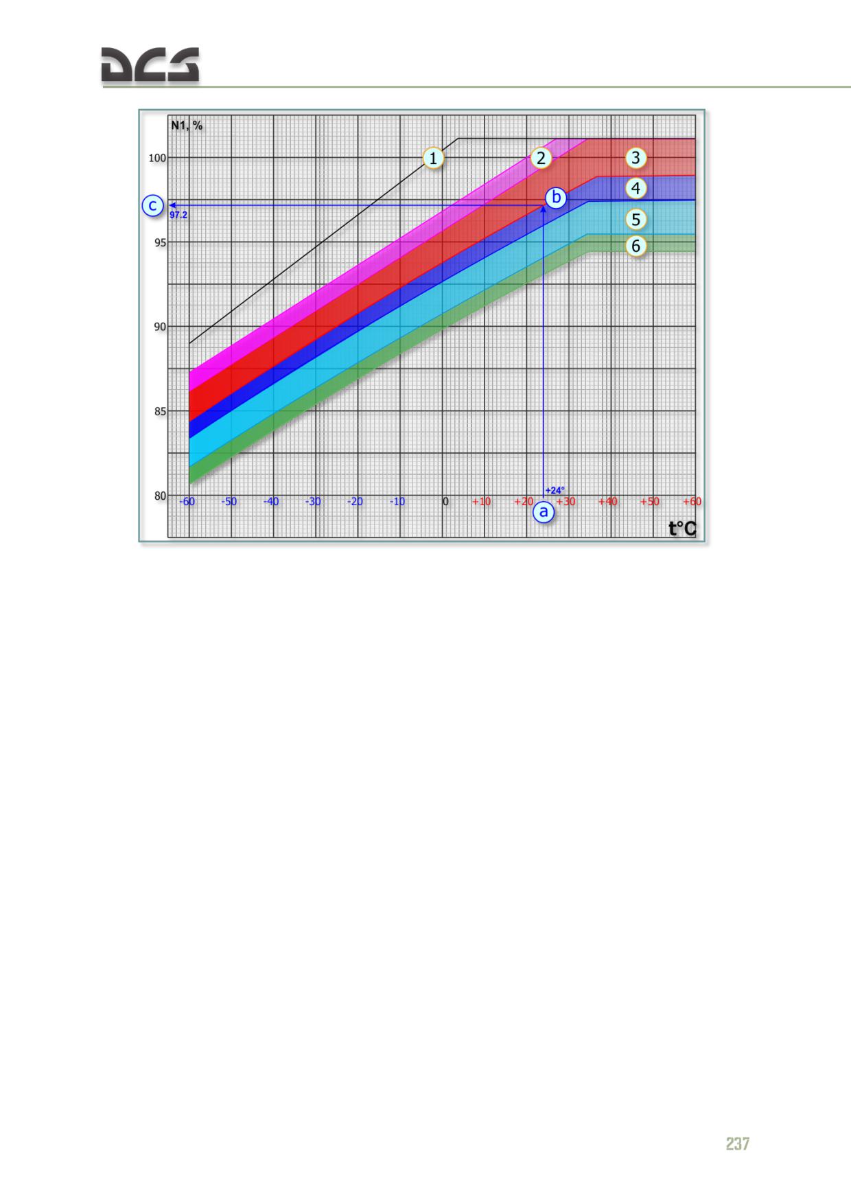
Fig. 8.4. N1% Limits Adjusted for Ambient Temperature
1. Maximum allowed N1 at standard atmospheric
4. MAX LTD CRUISE Power area
pressure
5. LTD CRUISE Power area
2. MAX RATED Power area
6. CRUISE Power area
3. TAKE OFF Power area
Example. Determine Maximum and Minimum N1 of Take-Off Power Setting mode for Ambient
Temperature at +24°C.
Key (for Minimum N1): enter the graph from the bottom applying the reported ambient temperature
(+24, a). Proceed vertically to the MIN Take Off power setting diagonals (b). Continue from the
intersecting point to the left to obtain the Minimum N1 (97.2%, c). Maximum N1 is 99.4%.
NOTE. This chart applies to standard atmospheric pressure. Apply the N1% established in this chart to
Fig. 8.5, N1 Adjusted for Barometric Pressure to find the N1 for the power setting required.
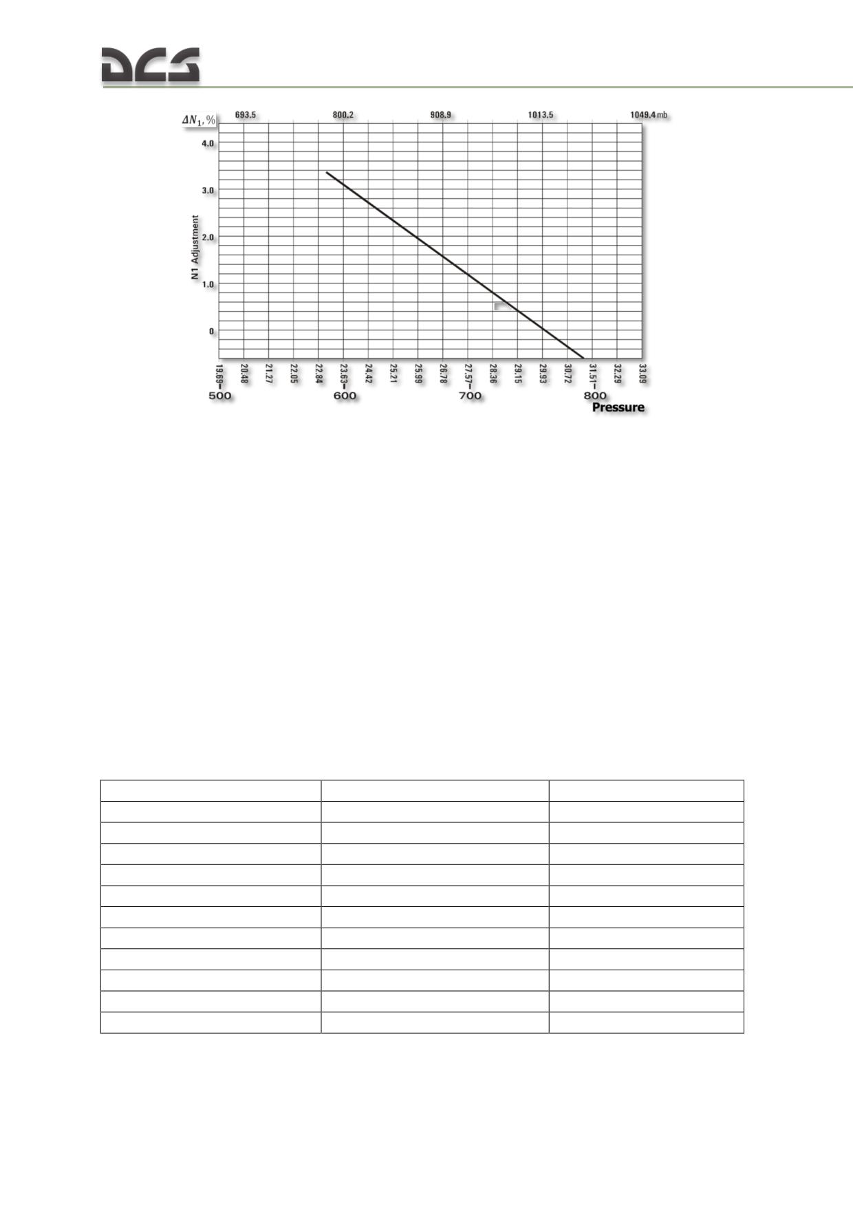
Fig. 8.5. N1% Adjusted for Barometric Pressure
8.3.2. Transmition limits
Main Transmition Maximum Operating Limits:
a) oil pressure:
IDLE mode - > 0,5 kg/sm2;
other Power Setting mode - 3.5±0,5 kg/sm2;
b) oil temperature:
MAX 90°С;
recommended 50 - 80°С;
MIN Initial Oil Temp (for operating more IDLE) -15°С;
MIN Oil Temp Continuous Operation +30°С.
c) Main Rotor RPM limitations see Table 8.9
Table 8.9
Absolute Limits:
RPM, %
MAX Time Allowed
MAX Rated & Take-Off Power
103%Maximum
10 Seconds
MAX Rated & Take-Off Power
88% Minimum
30 Seconds
All Settings above LTD Cruise
101%Maximum
20 Seconds
All Settings below LTD Cruise
103%Maximum
20 Seconds
Normal Operating Limits:
RPM, %
MAX Time Allowed
IDLE
55 to 70 (40 to 55 Single Engine)
20 Minutes
CRUISE
97% Maximum
Not Limited
LTD CRUISE
97% Maximum
60 Minutes
MAX LTD CRUISE
97% Maximum
60 Minutes
TAKE OFF
94% Maximum
6 to 15 Minutes
MAX RATED POWER
94% Maximum
6 to 60 Minutes
MAX oil temperature in Intermediate gearbox and Tail rotor gearbox is 110°С.
238
9
NORMAL PROCEDURES
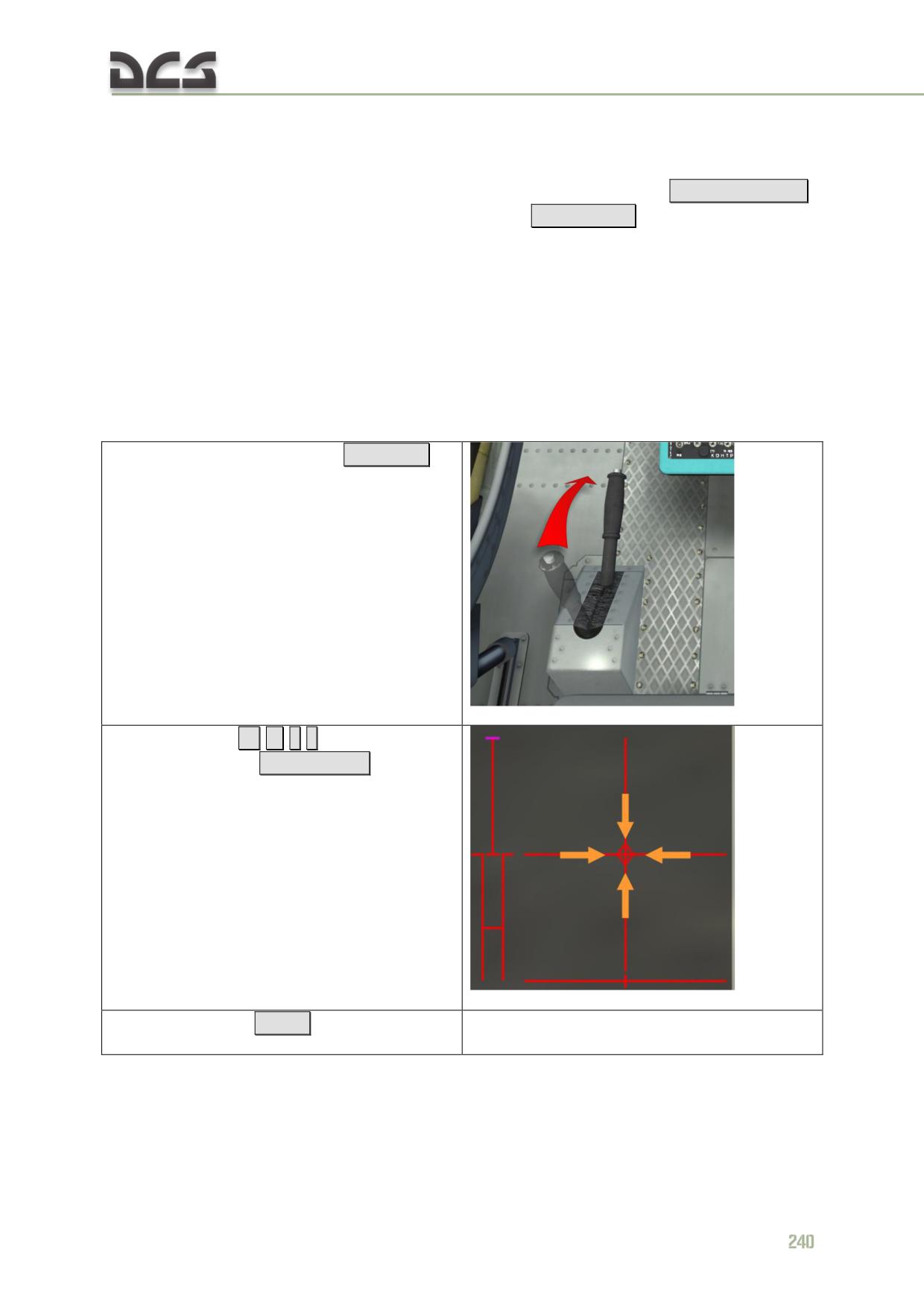
DIGITAL COMBAT SIMULATOR Mi-8МТV2
9. NORMAL PROCEDURES
The automatic start-up procedure can be activated by pressing
LWIN + HOME
Automatic shut down can be activated by pressing
LWIN + END
Below contains steps in two variants: SIMPLIFIED PROCEDURE (the minimum necessary
action) and a FULL PROCEDURE (full set of actions). In addition, if any item (in table)
can be skipped, it is marked by *
9.1. Preflight cockpit check
9.1.1. Simplified procedure
Ensure the controls are properly set for start:
1. Rotor brake - DOWN (unlock)
RCtrl + R
2. Cyclic - CENTER ←
→
↑
↓
For activate indicator
LCrtl + Enter
3. Collective- DOWN
Num -
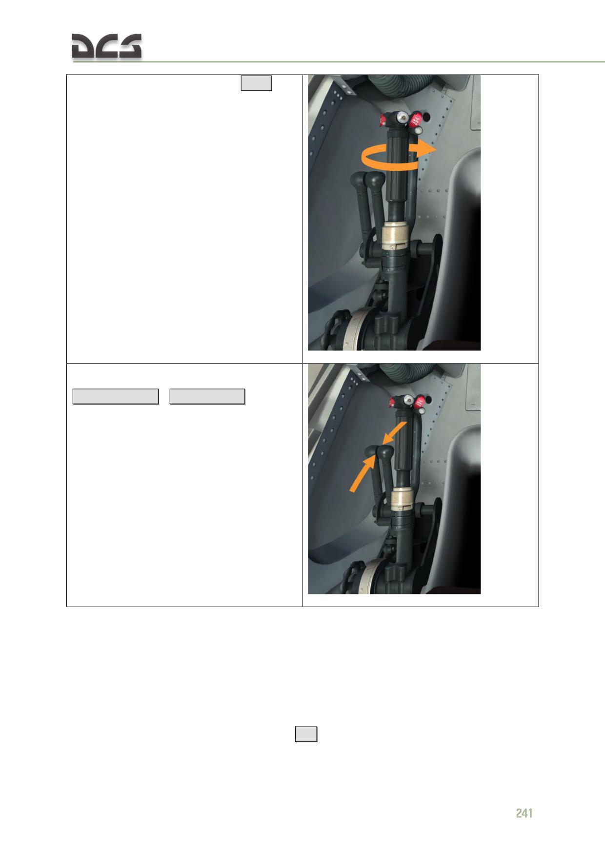
4. Throttle - FULL LEFT (Idle Power)
PgDn
5. Engine Power Levers - MIDDLE (standart
power setting for normal operation)
RCTRL + HOME
/
RCTRL + END
9.1.2. Full procedure
Perform the following cockpit checks prior to flight:
Make sure that the braking system is leak-free and operates normally
(after depression of the brake handle and attainment of a pressure of 31
to 34 kg/cm2 in the brake line there should be no noise created by
outgoing air and, after releasing the brakes, there should be no residual
pressure in the brake system)
[W]
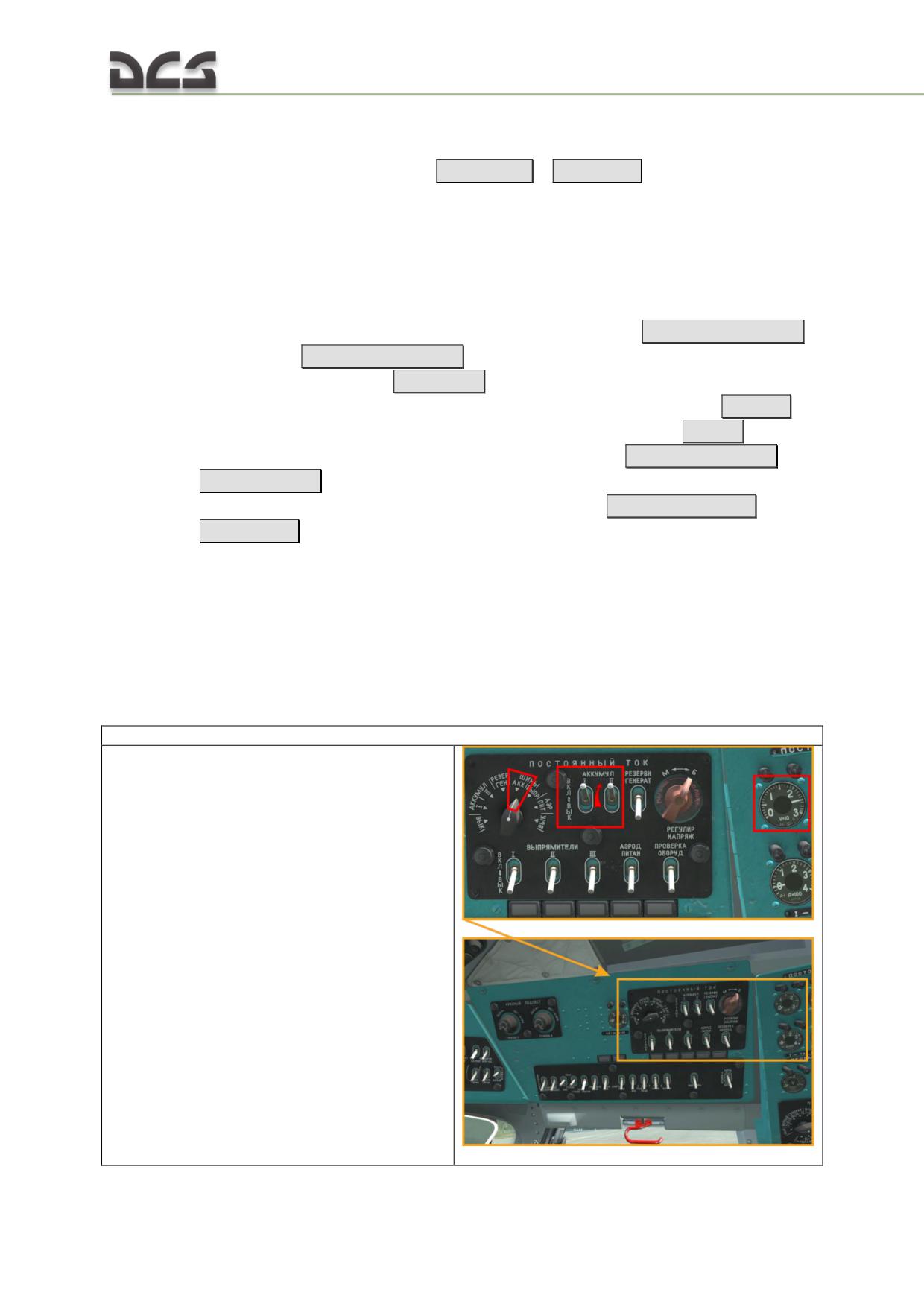
Set the pressure altimeter pointers to zero and check the barometric
pressure display for compliance with the actual aerodrome pressure with
an accuracy of ±1.5 mm Hg
[LShift + B]
/
[LCtrl + B]
energize the helicopter electrical systems
check crew intercommunication over the SPU-7 ICS (in case multicrew
game)
check windshield wiper operation
check and set the clock;
check fuel quantity on the fuel gauge and set the fuel gauge selector to
"РАСХ" (SVC CELL) [2] (move to the co-pilot's seat),
[RCtrl + RShift + V]
for CW turn
[RCtrl + RShift + B] for CCW turn.
release the rotor brake
[RCtrl + R]
(down)
make sure the collective pitch control lever is at the lower stop [Num -]
and the throttle control twist grip is turned fully to the left
[PgDn]
, the
engines throttle levers are set in the neutral detent
[RCTRL + HOME /
RCTRL + END]
, the control stick is in a position close to neutral and the
fuel shutoff levers are in the aft (closed) position
[ RCtrl + PageUp..
PageDown]
9.2. Preparation and equipment check procedures preceding
APU start
The power supply is required to start the APU. APU start can be made with or using
batteries (A), or an external power supply (B).
9.2.1. Simplified procedure
A. Turn on onboard electrical power:
1. Right Side Panel - DC POWER:
АККУМУЛ I, II (Battery 1, 2) - ON (UP),
check the voltage of the battery bus by setting
the DC selector knob to "ШИНЫ АКК." (BATT
BUS). The voltage should be no less than 24 V.
242
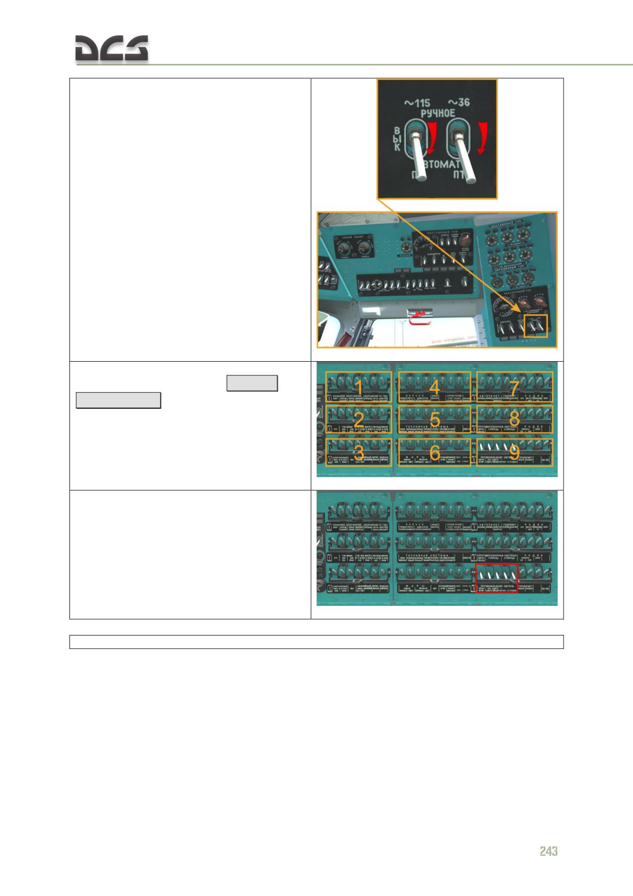
2. Right rear console - AC: ~115 (inverter 115V)
- set to "РУЧНОЕ" (MANUAL) (needed for
manometers and TV3-117VM exhaust gas
temperature gauges operation).
Note. When doing cold start from batteries, to
prevent them from fast discharge, it is
recommended to leave the 36V inverter switch
in neutral position, until generators are
operating.
3. Left and Right Circuit Breaker Panels:
All circuit breakers - ON
RCTRL +
RSHIFT + 4... 9
(1..3 for Weapon System)
4. ПРОТИВООБЛЕДЕНЕНИЕ (Anti-ice Control,
Left Engine, Right Engine) circuit breakers - OFF
(unless required)
B. Connecting to external electrical power:
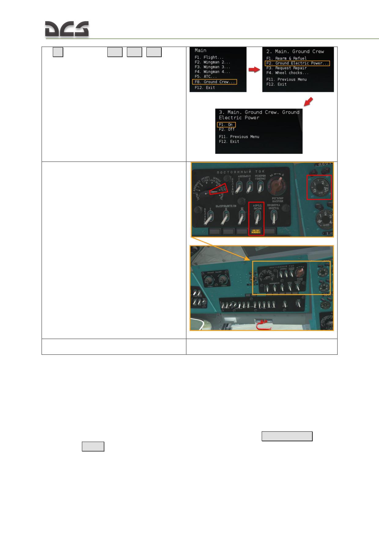
5.
[\]
(Radio Menu),
[F8]
,
[F2]
,
[F1]
(Connect Ground Electric Power).
6. Once the "АЭР. ПИТ. ВКЛЮЧЕНО" (EXT PWR
ON) light illuminates (after successful connection
to an external power source), and check the DC
ground power source voltage by setting the DC
selector knob to "АЭРОДРОМ. ПИТАН." (EXT
PWR). The voltage should be within the limits of
27 - 29 V.
7. Follow the procedures, described in the
chapter A
9.2.2. Full procedure
While performing complete preparation procedure, one must connect power sources
and continue extensive control and preparation of equipment for start.
Connection of power supplies
A. Turning on the batteries:
"АККУМУЛ. I" и "II" (BATT I, II) to "ВКЛ." (ON (up)) [LCtrl + LShift
+ 1..2]
;
check the voltage of the battery bus by setting the DC selector knob to
"ШИНЫ АКК." (BATT BUS). The voltage should be no less than 24 V.
check the condition of the batteries as follows:
244
a) "АЭРОДР. ПИТАН." (EXT PWR (external power)) selector to "ВЫКЛ."
(OFF) [LCtrl + LShift + 7]
;
b) DC selector knob to "АККУМУЛ. I" (BATT I)
[LCtrl + LShift + 9..0]
c) "АККУМУЛ. II" (BATT II) to "ВЫКЛ" (OFF (down))
[LCtrl + LShift +2]
d) any fuel boost pump to ON and check Volts (no less than 24 V)
[RShift
+ 1]
e) DC selector knob to "АККУМУЛ. II" (BATT II)
[LCtrl + LShift + 9..0]
f) АККУМУЛ. II" (BATT II) to "ВКЛ" (ON (up))
[LCtrl + LShift +2] and
"АККУМУЛ. I" (BATT I) to "ВЫКЛ" (OFF (down))
[LCtrl + LShift +1]
Check voltage (no less than 24 V).
g) fuel boost pump to OFF
[RShift + 1]
;
h) "АККУМУЛ. I" и "II" (BATT I, II) to "ВКЛ." (ON (up))
[LCtrl + LShift
+ 1..2]
;
i) DC selector knob to "ШИНЫ АКК." (BATT BUS) [LCtrl + LShift + 9..0]
B. Connecting to external electrical power:
To connect to an external power source on the ground:
DC EXTERNAL POWER: once the "АЭР. ПИТ. ВКЛЮЧЕНО" (EXT PWR ON)
light illuminates, then
[LCtrl + LShift + 7]
, check the DC ground power
source voltage by setting the DC selector knob to "АЭРОДРОМ. ПИТАН."
(EXT PWR). The voltage should be within the limits of 27 - 29 V.
AC EXTERNAL POWER (in DCS this occurs simultaneously with the DC power
supply): once the "АЭР. ПИТ. ВКЛЮЧЕНО" (EXT PWR ON) light
illuminates (after successful connection to an external power source), then
[LAlt + LShift + `]
, check the ground power source voltage by setting the
AC selector knob to "АЭРОДРОМ. ПИТАН." (EXT PWR). The voltage
should be within the limits of 200 - 205 V. Set the "АЭРОДРОМ. ПИТАН."
(EXT PWR) switch to "ВКЛ." (ON). Set the "ПО-500А ~ 115" (Inverter 1)
and "ПТ-200 ~ 36" (Inverter 2) switches to the "АВТОМАТ" (AUTO)
(down) postion. Set the "ВЫПРЯМИТЕЛИ I, II, III" (RECTIFIERS 1, 2, 3)
to the "ВКЛ." (ON) (up) position. Check the rectifier bus voltage by setting
the DC selector knob to "ШИНЫ ВЫПР." (RECT BUSES). The voltage
should be within the limits of 27 - 29 V.
o set the AC selector knob to the "~115" position. The voltage should be
115 V.
o Set the "АЭРОДР. ПИТАН." (EXT PWR) switch to "ВКЛ." (ON) and the
Inverter 115 switch to "РУЧНОЕ" (MAN).
o Check the inverter output voltage by setting the AC selector knob to
"~115". The voltage should be 115 V.
Equipment preparation and check procedures, continued
switch ON all the circuit-breakers and switches required for starting the
APU and main engines (the starting system, ignition systems for the APU
and main engines, fire protection system, hydraulic systems, trim
actuators, fuel tank pumps, fuel quantity gauge, engine anti-icing system,
friction clutch, electric clutch, gyro correction cutout switch, attitude
indicator, directional gyro, autopilot, voice warning system, tail rotor pitch
limit system, cockpit voice recorder, anti-collision light
[RCTRL + RSHIFT
+ 1... 9]
make sure the AC generator switches are set to "ВЫКЛЮЧЕНО" (OFF)
(down)
[LAlt + LShift + 1..2]
make sure that РИ-65 (RI-65) switch is in the ВЫКЛ. (OFF) position and
the corresponding light panel ВКЛЮЧИ РИ-65 (ENABLE RI-65) is on;
make sure that the СПУУ-52 (SPUU-52) switch is in the ВЫКЛ. (OFF)
position and the corresponding red light-button on the center console is
on;
check that helicopter has enough fuel, using fuel meter, after check
procedure, set the switch to the "РАСХ." (FEED TANK) position (player
must take the co-pilot seat) [RCtrl + RShift + V]
rotation clockwise,
[RCtrl + RShift + B]
rotation counterclockwise;
check that squibs of the fire extinguishers and fire signalization system are
operational according to the procedure described in the chapter 7.6.3
For night time operations:
flashlight
[LAlt + L]
(mouse control)
turn on red lighting of the instrument and control panels according 7.8.2
turn on the navigation lights
[RCtrl + 1..2]
(dimmed), the MSL-3 flasher
[RCtrl + 6]
and rotor tip lights
[RCtrl + 5]
(they must be turned on for
safety of the ground crew, in game it is not necessary).
9.3. Starting the APU and main engines
After preflight cockpit check and energizing electrical power sources, is required
preparing for APU and main engines start:
246
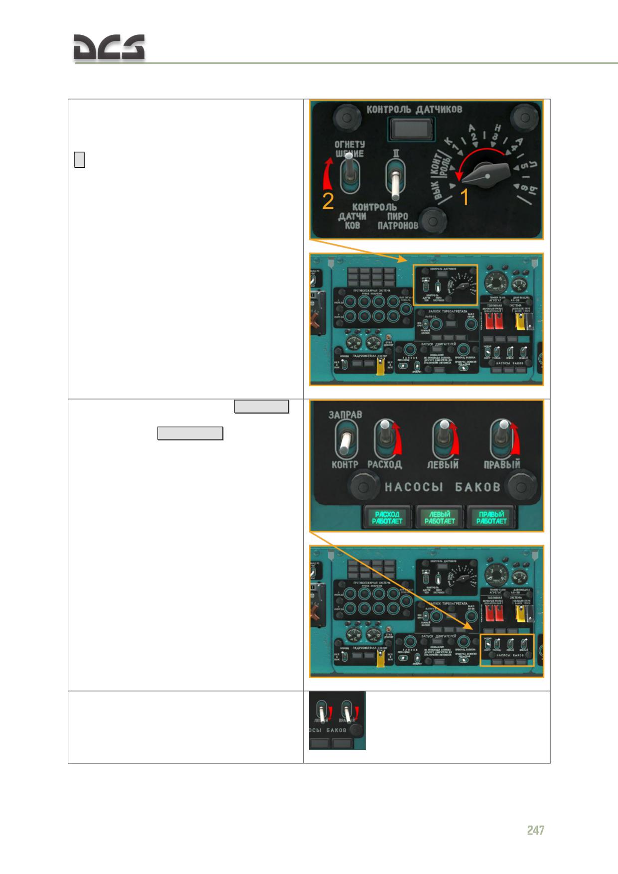
Final procedures before APU start
1. Set the selector knob of TEST fire signal
chanel swich to "ВЫК" (OFF), then "КОНТРОЛЬ
ДАТЧИКОВ - ОГНЕТУШЕНИЕ" (FIRE EXT/TEST)
switch to "ОГНЕТУШЕНИЕ" (EXT) (up, light out)
[]
2. Switch on the fuel boost pumps
[RShift + 1]
of the service tank and the fuel transfer pumps
of the main tanks
[RShift + 2..3]
Note. When performing cold start from
batteries, to safe batteries, it is recommended to
not enable transfer pumps, until APU generator
or rectifiers are operational.
NOTE. If during APU start will used battery only,
then it necessary fuel transfer pumps of the
main tanks set OFF
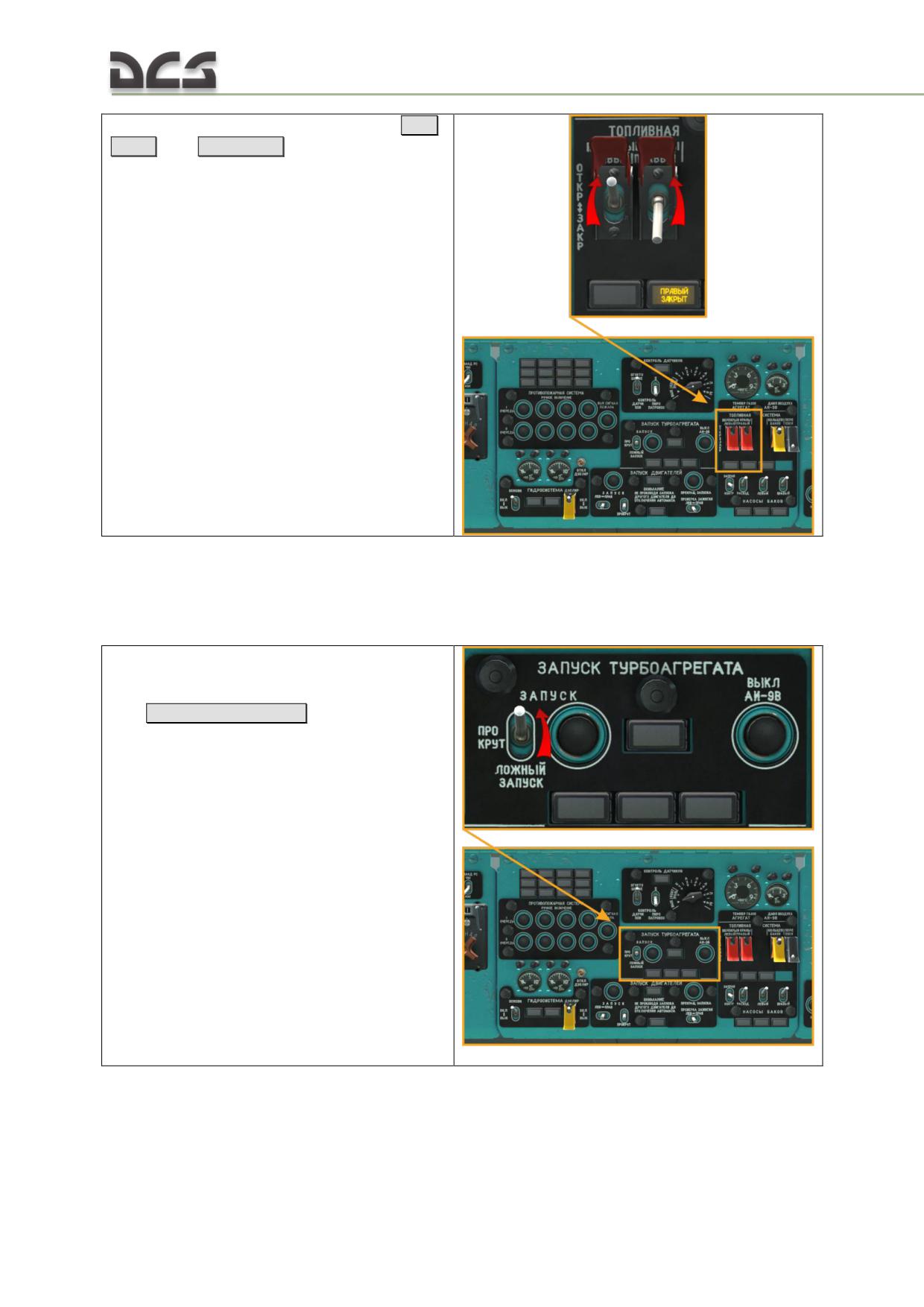
3. Open the fuel fire (shutoff) valves (UP)
[LAlt
+ 5..6]
then
[RAlt + 5..6]
*switch on the command radio and request clearance for engine start
Starting the AI-9v APU
Start the APU prior to starting the main engines:
1. "ЗАПУСК- ПРОКРУТ.- ЛОЖНЫЙ ЗАПУСК"
(START-CRANK-FALSE START selector on the
APU start control panel to "ЗАПУСК" (START)
(UP)
[RCtrl + E] / [RAlt + E]
248
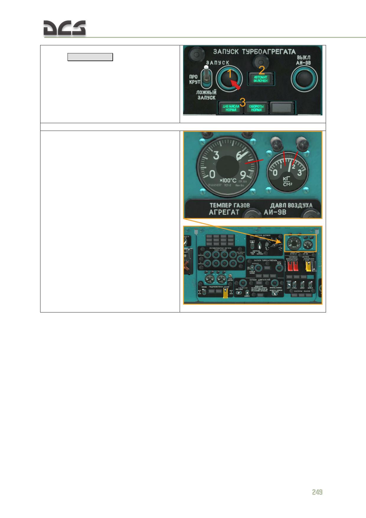
2. Press the "ЗАПУСК" (START) button for 2 to 3
seconds
[RShift + Home]
. The "АВТОМАТ.
ВКЛЮЧЕН" (AUTO IGNITION) light should
illuminate. The APU automatically accelerates to
idle speed, indicated by illumination of the "ДАВ.
МАСЛ. НОРМА" (OIL PRESS NORM) and
"ОБОРОТЫ НОРМА" (NORMAL SPEED) lights.
The time to reach idle speed should not exceed
20 seconds.
Once the APU reaches idle speed, check its operational parameters and make sure:
continuous idle EGT does not exceed
720°С;
"ДАВ. МАСЛА НОРМА" (OIL PRESS
NORM) and "ОБОРОТЫ НОРМА"
(NORMAL SPEED) lights illuminate;
air pressure reading in the APU main air
bleed line (APU pressure gauge) is within
normal parameters (1.3-2.0 kg/sm2);
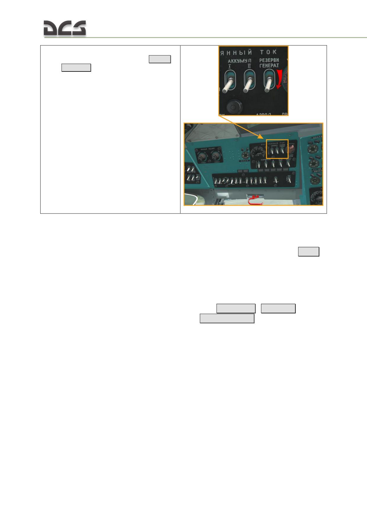
"РЕЗЕРВН. ГЕНЕРАТ." (STBY GEN) switch
is set to "ВЫКЛ." (OFF) (down)
[LCtrl +
LShift + 3]
The APU must run for a minimum of 1 minute before attempting to start the main
engines.
In case of an inadvertent shutdown of the APU, press the "ВЫКЛЮЧЕНИЕ АИ-9В"
(APU OFF) button for 2 to 3 seconds in order to cut off fuel supply to the APU
[End]
The APU start can be aborted at any time by pressing the "ВЫКЛЮЧЕНИЕ АИ-9В"
(APU OFF) button for 2 to 3 seconds.
In case of an unsuccessful APU start, crank the APU as follows:
set the "ЗАПУСК - ПРОКРУТ. - ЛОЖНЫЙ ЗАПУСК" (START-CRANK-
FALSE START) selector switch to (CRANK) [RCtrl + E]
/
[RAlt + E]
;
press the "ЗАПУСК" (START) button
[RShift + Home]
and check that the
"АВТОМАТ. ВКЛЮЧЕН" (AUTO IGNITION) and "ДАВ. МАСЛА НОРМА"
(OIL PRESS NORM) lights illuminate.
Restart attempts must be 3 minutes apart. Three attempts can be made. If the unit
does not start after three attempts, a 15 minute shut-down/cooling period must
follow before another start is attempted.
Continuous APU operation is limited to
30 minutes. In "РЕЗЕРВН. ГЕНЕРАТ"
(STANDBY/GEN) mode, the APU cannot be operated beyond 30 minutes, after which
a 15 minute shut down/cooling period is required. Cool down the APU 15 minutes
between shutdown and restart. Run the APU a minimum of 1 minute before
shutdown.
Three consecutive attempts to start the main engines via APU bleed air are allowed.
The duration of each air bleed cycle should not exceed 45 seconds with intervals
between the air bleed cycles no less than 1 minute, during which the APU is run at
250
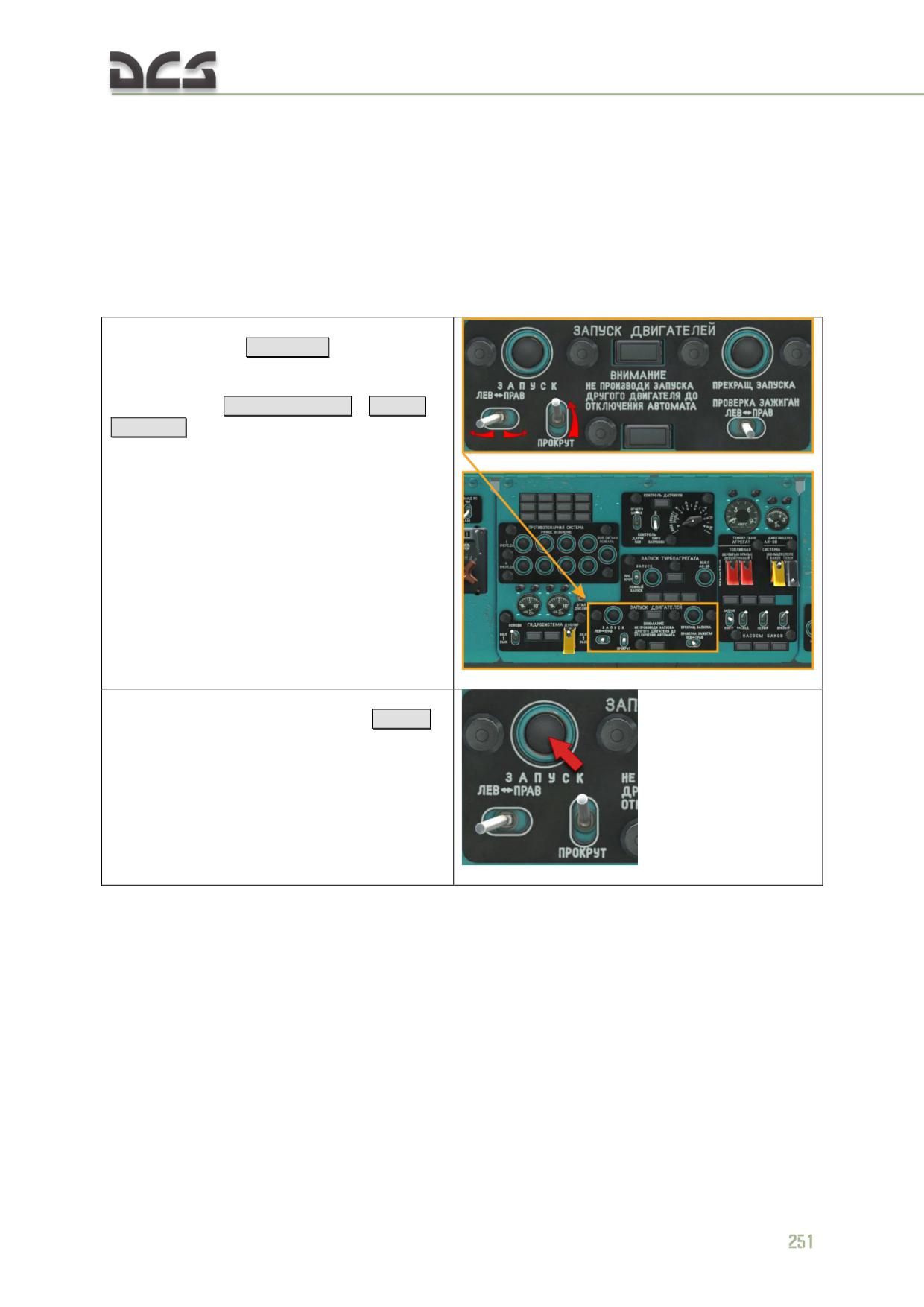
idle speed. The continuous running time of the APU in this condition should not
exceed 13 minutes, followed by a 15 minute shut down/cooling period.
Do NOT start the main engines with the APU in DC generator mode (STBY GEN
switch on the right side console ON (up)).
Starting the TV3-117VM Main Engines
The engines starting order depends on the wind direction. The engine on the
downwind side is started first.
1. Set the start mode selector switch to
"ЗАПУСК" (START)
[LShift + E]
and the "ЛЕВ. -
ПРАВ." (LEFT - RIGHT) engine selector switch to
the desired engine for start (downwind first,
upwind second)
[RAlt + RShift + E]
/
[RCtrl +
RShift + E]
2. Press the "ЗАПУСК" (START) button for 2 to 3
seconds to initiate the start sequence
[Home].
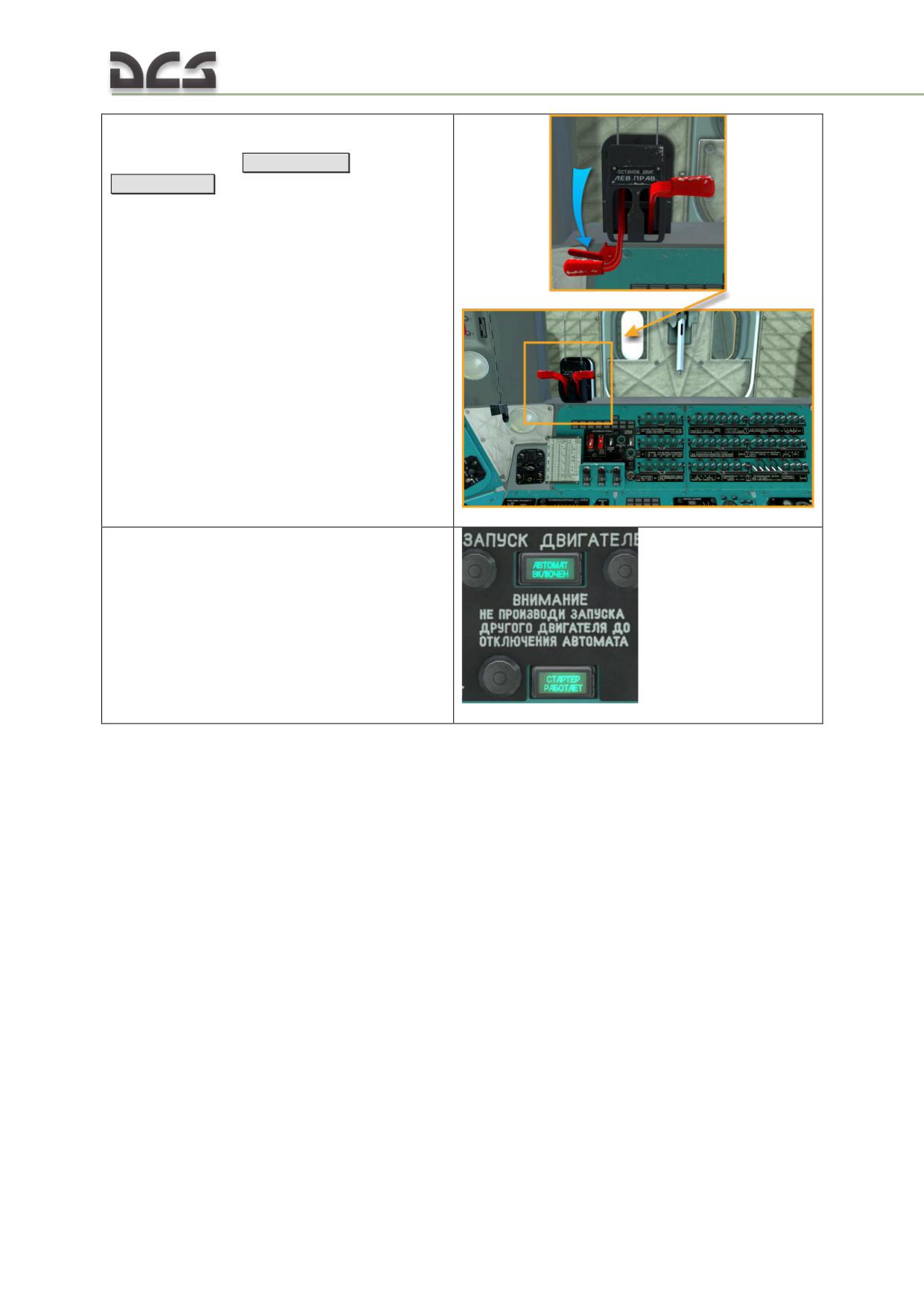
3. Open (set forward) the fuel shutoff lever of
the engine being started when N1 (compressor)
RPM begins to rise
[ RCtrl + PgUp]
(left) /
[RCtrl + PgDn]
(right)
4. The engine should reach idle speed within 60
seconds. The "АВТОМАТ. ВКЛЮЧЕН" (AUTO
IGNITION ON) and "СТАРТЕР РАБОТАЕТ"
(STARTER ON) lights should illuminate during
the start.
252
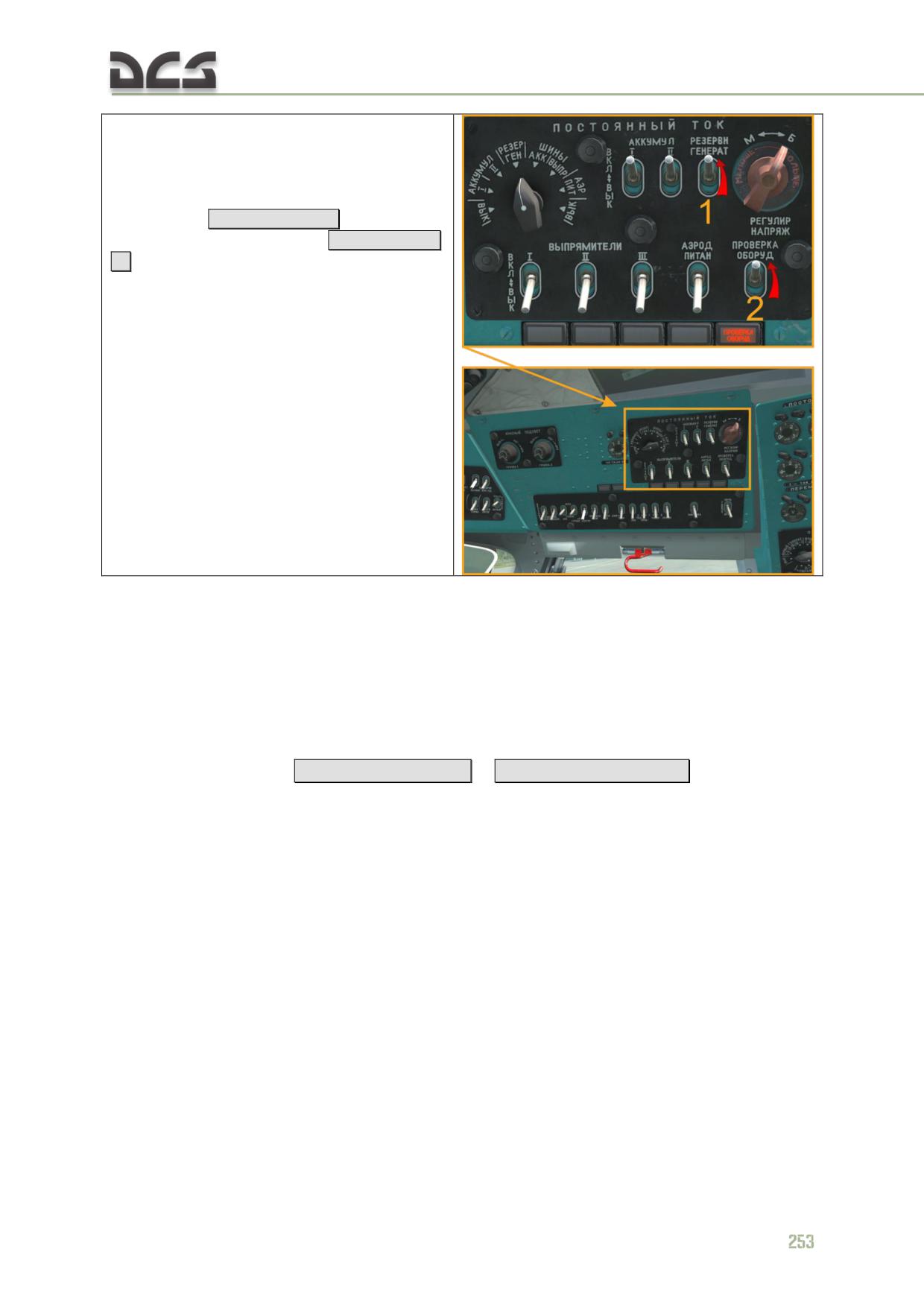
5. If engine startup is performed with use of
onboard batteries only, then after the first
engine has been started, connect onboard
power consumers to the APU generator by
setting the "РЕЗЕРВН. ГЕНЕРАТ." (STANDBY
GENERATOR)
[LCtrl + LShift + 3] и "ПРОВЕРКА
ОБОРУД.") (EQUIPMENT TEST)
[LCtrl + LShift +
8]
into the "ВКЛ." (ON) positions.
After completion of the automatic starting cycle the lights should turn off (AUTO
IGNITION ON light in 30 seconds; STARTER ON light upon N1 RPM reaching 60-
65%).
Unusual thumps or impact noises during main engine start and rotor spin up indicate
the main rotor blades centrifugal droop limiters are hitting their stops. Carefully
adjust the cyclic control stick position until the noise is eliminated.
Set the "ЛЕВ. - ПРАВ." (LEFT - RIGHT) engine selector switch to the second starting
engine (upwind side)
[RAlt + RShift + E]
/
[RCtrl + RShift + E] and repeat the
starting procedure for the second engine.
With both engines started and running at idle speed, the Nr (main rotor) RPM should
stabilize within 55-70%.
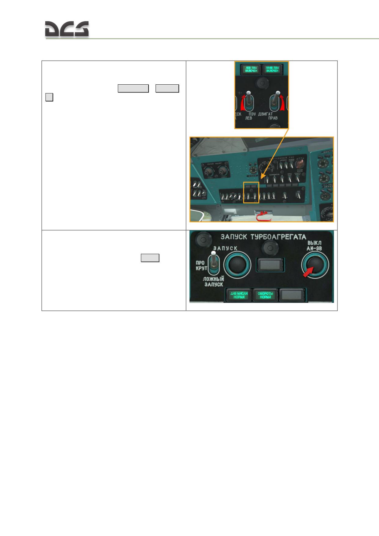
Immediately after starting the engine ..
6. Switch on the PZU particle separators for both
engines by setting the "ПЗУ ДВИГАТ.
ЛЕВ./ПРАВ." (PZU LH/RH) switches to the
"ВКЛ" (ON (up)) position
[LCtrl + D]
/
[RCtrl +
D]
. Check the "ЛЕВ. ПЗУ ВКЛЮЧЕН." (LH PZU
ON) and "ПРАВ. ПЗУ ВКЛЮЧЕН" (RH PZU ON)
lights to illuminate (for up to 30 seconds).
7. After successfully starting the main engines,
allow the APU to cool down at idle speed for 0.5
- 1 min and shut the APU down by pressing the
"ВЫКЛ АИ-9В" (APU OFF) button
[End].
254
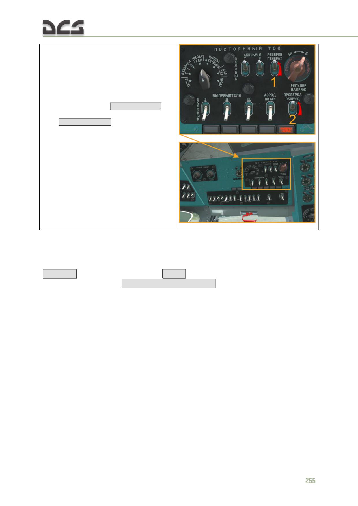
8. If engine startup is performed from batteries
only, then do not turn of the AI-9V until engines
have been warmed up and main rotor has
reached RPM of 88%. To supply onboard
consumers during the idle mode and when the
first engine has been started and second has
not, enable the STG-3 (see phase 5.) generator
by switching the "РЕЗЕРВН. ГЕНЕРАТ."
(STANDBY GENERATOR)
[LCtrl + LShift + 3]
и
"ПРОВЕРКА ОБОРУД.") (EQUIPMENT
TEST)
[LCtrl + LShift + 8]
to the "ВКЛ." (ON)
positions. Note. If before APU start the transfer
pumps were off, to safe batteries power, now it
is time to enable them.
9.4. Engines warm up, Flight controls and Hydraulic systems
checks
Engine warm up is performed at idle power with collective lowered to minimum
[Num - ]
, throttle turned fully left
[PgDn]
, engine condition levers set in the idle
detent (middle) position
[RCtrl + Home / RCtrl + End]
Monitor the powerplant instrumentation during engine warm up. Warm up should not
exceed 1 minute.
Test the flight controls and hydraulic systems at idle power as follows:
*alternatively move the cyclic and pedals to make sure the controls move
smoothly without jamming;
*as the controls are moved, the main hydraulic system pressure should
vary within a range of 45±3 to 65±82 kg/cm2. Pressure in the reserve
hydraulic system should be approximately 5 kg/cm2.
The throttle can be set from full left to full right to accelerate the engines out of idle
power once the engine outlet oil temperature reaches +30°C and the main gearbox
oil temperature reaches at least -15°C.
Additional checks at idle (for in-depth study of the helicopter):
1. Check the utility and standby hydraulic systems;
2. Check the engine anti-icing system at idle;
3. Check the electronic engine governor, using channels ST1 and ST2:
switch on the "ЭРД ЛЕВ. ПРАВ" (ELECTRONIC ENGINE GOVERNOR LEFT RIGHT);
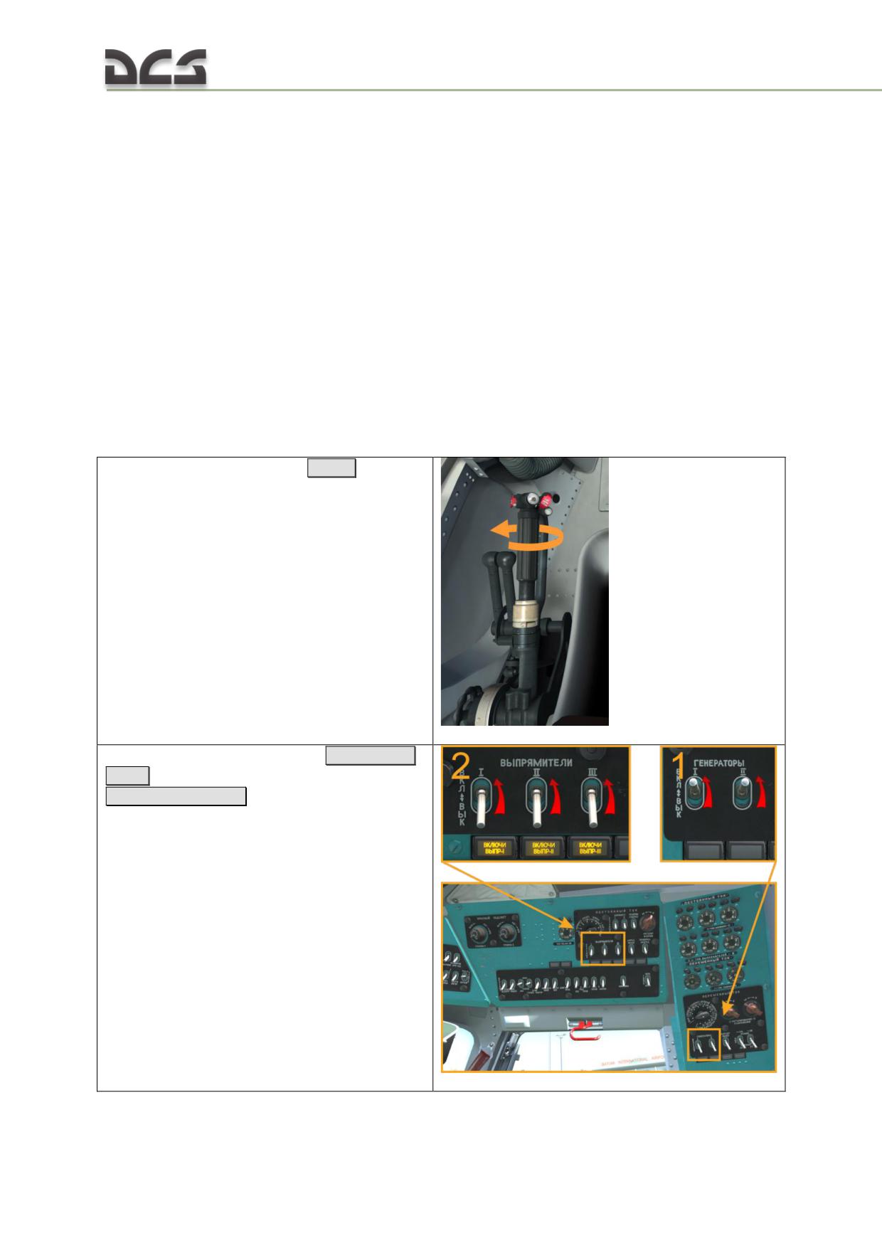
set the "КОНТРОЛЬ СТ-1 - РАБОТА - КОНТРОЛЬ СТ-2" (CHECK ST1 - OPERATION -
CHECK ST2) into the "СТ-1" (ST1) positiion;
gradually increase the main rotor RPM by twisting the throttle grip to the right (main
rotor pitch should be in the lower stop position), if nesessary, use the ECL handles, until
the yellow warning panels "ПРЕВ. Nст ЛЕВ. ДВ" (EXCEEDING RPM LEFT ENGINE),
"ПРЕВ. Nст ПРАВ (EXCEEDING RPM RIGHT ENGINE) go on. It should happen when
Nr (main rotor) = 91.5±2%;
gradually reduce Nr at 5÷7%, but not less than 88%, warning panels, mentioned above,
should remain on;
set the switch to the "СТ-2" (ST-2) position and repeat the check.
WARNING: When switching from position "СТ-1" (ST-1) to "СТ-2" (ST-2) one must hold
them in intermediate state for some time. Fast toggling from "СТ-1" (ST-1) to "СТ-2"
(ST-2) can cause engines shut off (not implemented in the game).
9.5. Engine run up, switching ON generators and rectifiers.
Avionics checks
А. Switching ON generators and rectifiers
1. Rotate the throttle full right
[PgUp]
2. Set the AC generators 1 and 2
[LAlt + LShift
+ 1..2] and rectifiers switches (1..3) to ON
[LCtrl + LShift + 4..6]
256
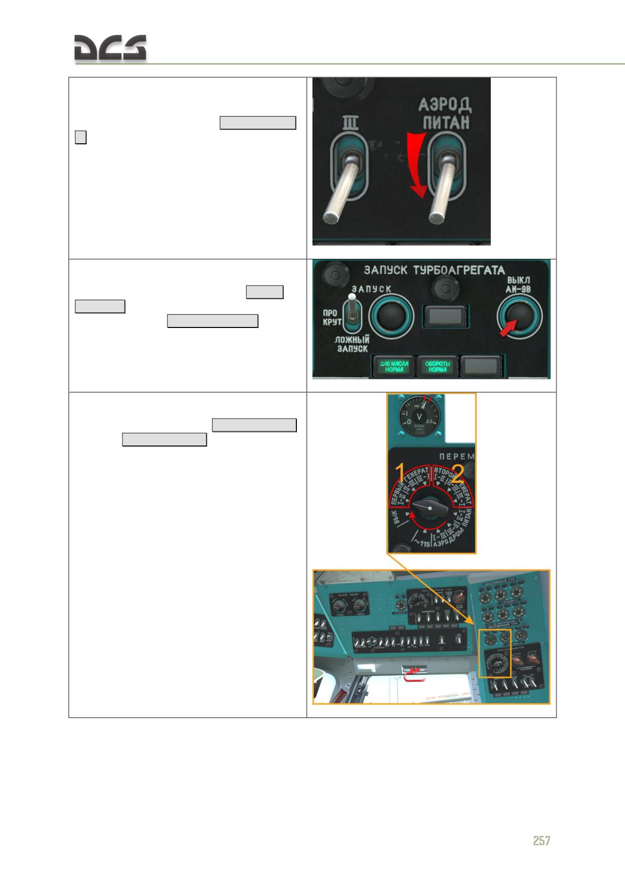
3. Request external power to be switched off.
When the "АЭР. ПИТ. ВКЛЮЧЕНО" (EXT PWR)
light turns off, set the "АЭРОДР. ПИТАН." (EXT
PWR) selector switches of OFF
[LCtrl + LShift +
7]
4. If APU generator was enabled, now it is time
to turn it off, by setting the "РЕЗЕРВН.
ГЕНЕРАТ." (STANDBY GENERATOR)
[LCtrl +
LShift + 3]
и "ПРОВЕРКА ОБОРУД.")
(EQUIPMENT TEST)
[LCtrl + LShift + 8]
into the
"ВЫКЛ." (OFF) positions and the disable the
APU.
5*. Check
the AC generators output voltage to be
within 200 to 205 V,
[LAlt + LShift + 7]
/
[LAlt + LShift + 8]
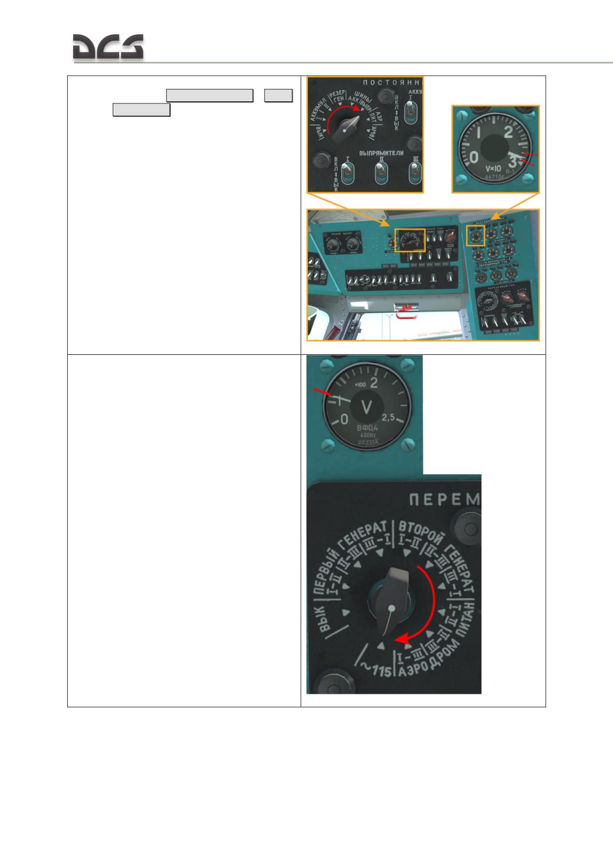
the rectifiers output voltage to be within
27 to 29 V, [LCtrl + LShift + 9]
/
[LCtrl
+ LShift + 0]
the transformer output voltage to be
115 V.
258
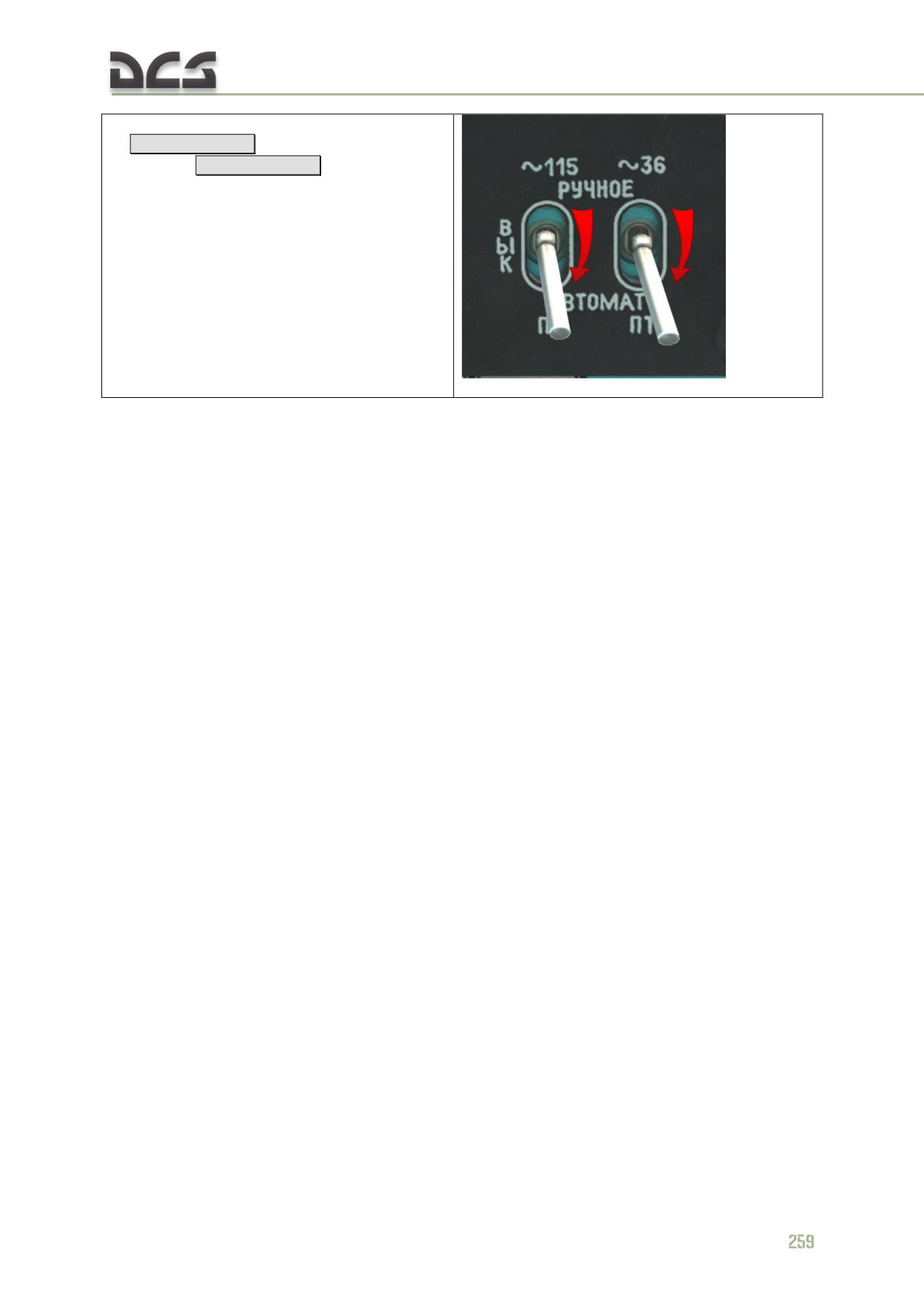
6. Set (or check) the ПО-500 ~115 V (Inverter
1)
[LAlt + LShift + 3] and ПТ-500 ~36 V
(Inverter 2)
[LAlt + LShift + 5]
inverters to the
АВТОМАТ (AUTO (down)) position.
Additional checks
at with fully opened (all the way to the right) throttle (for in-depth study of the helicopter):
1. Check the anti-icing system of the engines at right throttle. After 25-40 seconds from the moment
when the system was enabled, can increase: the gas temperature in front of compressor’s rotor (not
more than 600C) and Ntc (Turbine compressor RPM) (not more than 2%).
2. Check engines response:
rotate the throttle twister all the way to the right (clockwise) and operate in this mode
for 1 min;
remember RPM of the turbine compressor;
rotate twister all the way to the left (counterclockwise);
rotate throttle twister all the way to the right within 1-2 seconds and measure time from
the beginning of rotation to the moment when the RPM of turbine compressor reaches
RPM, which is 1-1.5% less than one, observed on the fully opened throttle;
engines response should be within 3-6 seconds range.
3. Transition to the generator mode: 1st generator -"вкл" (on), using the rotating switch, measure the
interphase voltage, 2nd generator -"вкл" (on), measure the interphase voltage, set the rotating switch
to the "115 в" (115 V) position.
4. Enable and check rectifiers (ВУ) - "вкл" (ON), enabling them one by one and checking current
using ampermeter;
5. Check the system adjusting main rotor RPM:
set the collective to 3o according to the main rotor pitch angle indicator, when throttle is
twisted all the way to the right, oil temperature in the main driveshaft must be not less
than 300 C;
deflect the N2 trim INCR-DEC switch downward and after main rotor RPM has settled,
check the value of main rotor RPM, it should be within 91±2%;
deflect the switch upward and make sure that the main rotor RPM is within 96..99%;
if the upper limit of the main rotor RPM has not been reached, warm up oil in the main
driveshaft to 40-60°С and repeat the check;
after checking the main rotor RPM range, by deflecting the N2 trim INCR-DEC switch, set
a main rotor RPM of 94..95% and lower the collective all the way down.
5. Check anti-icing system of main rotor, tail rotor, windshileds and dust protection devices (if
necessary) according to 7.4.6
7. "Обогрев ПВД" (Pitot tube heating) - check (if necessary);
8. SPUU-52- check:
enable the circuit breaker on the right circuit breaker console, enable the "СПУУ-52"
(SPUU-52) on the left triangular panel;
return pedals to the neutral position;
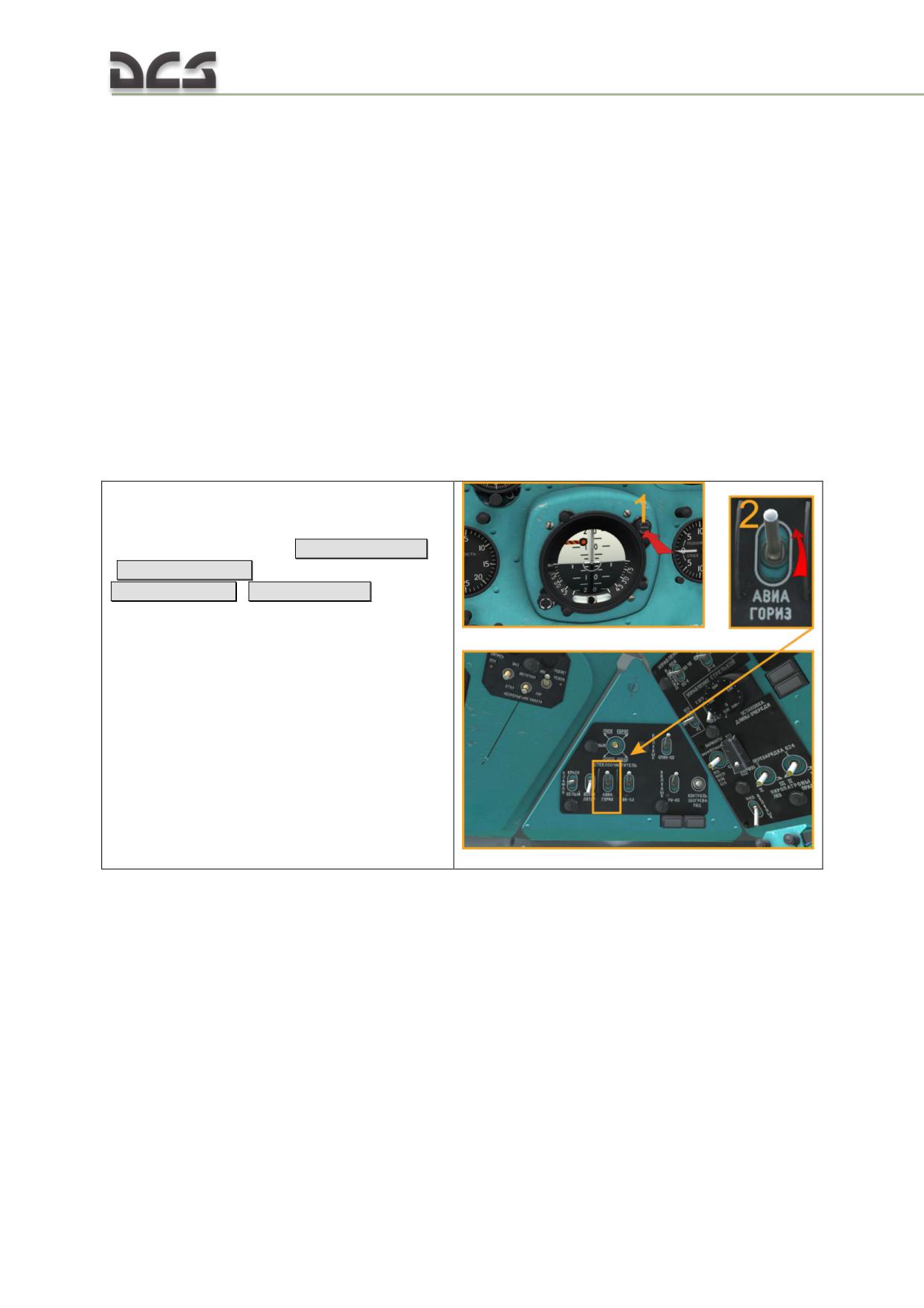
press the "откл" button (lamp goes on), set the indicator to the middle position;
by keeping the the "откл" button pressed, set the spring loaded switch to the “t”
position, pointer on the indicator deflects to the right mark, then to the “P” position -
pointer deflects to the left mark;
release the button and the switch - lamp button goes off, and pointer on the indicator
returns to the middle position;
press the "откл" button and while keeping it pressed, by rotating the "Контроль"
(CHECK) knob, deflect the pointer all the way to the right;
disable the the "СПУУ-52" (SPUU-52) and release the lamp-button, pointer on the
indicator should deflect all the way to the left, while lamp-button continues being on;
enable the the "СПУУ-52" (SPUU-52), press the lamp-button and while keeping it
pressed, by the "Контроль" (CHECK) knob set the pointer to the middle position;
during flight the zero pointer on the indicator can deflect itself to the left, when ambient
temperature increases or air pressure reduces.
B. Avionics check
Switch on all the flight, navigation, radio communication and electronic equipment
required for the flight, and test for proper functioning.
7. Prior to powering up the АГБ-3К (AGB-3K)
attitude indicator, cage the device by pressing
the "АРРЕТИР" (CAGE) button: pressing the
"АРРЕТИР" (CAGE) button
[LCtrl + LShift + N]
(
[RCtrl + RShift + N] for right) and switch on
[LAlt + LShift + G]
(
[RAlt + RCtrl + P]
for right)
and test the attitude indicator
260
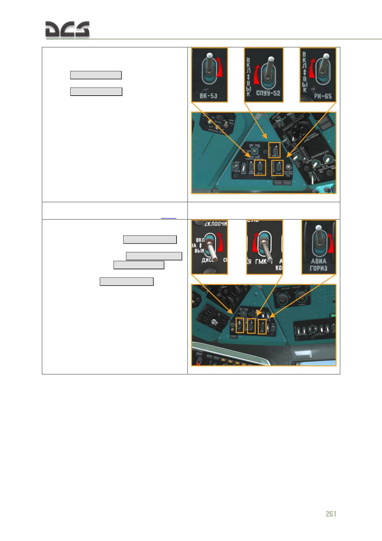
8. Switch on:
the ВК-53РШ (VK-53RSh) gyro
correction cutout switch
[LAlt + LShift + F]
;
the СПУУ-52 (PITH LIM SYS)
[LAlt + LShift + T]
;
the РИ-65 (INF REP) [not assigned]
9*. Switch on the ADF and tune to the desired
channel/frequency (detailed instructions here);
10. Switch on:
the "ДИСС-15" (DISS-15) Doppler
navigation system
[RAlt + RShift + T]
;
the right AGB-3K: pressing the
"АРРЕТИР" (CAGE) [RCtrl + RShift + N]
and switch on
[RAlt + RCtrl + P]
;
the gyromagnetic compass ГМК-1А
(GMK-1A)
[RAlt + RShift + U]
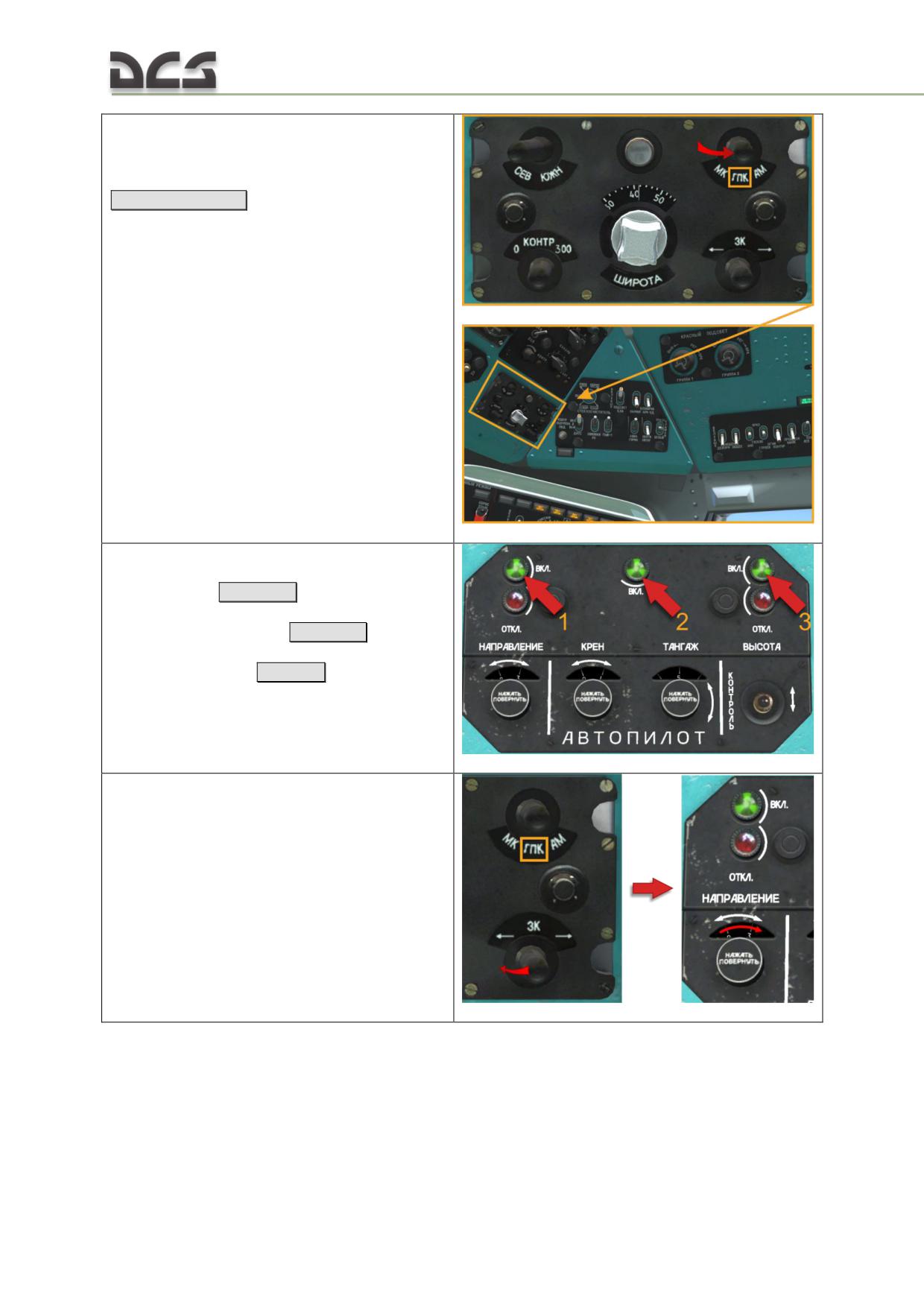
11*. When directional gyro heading arrow
settles on the starting ground course, set the
ГМК-1А (GMK-1A) gyromagnetic compass to
ГПК (directional gyro) mode
[RCtrl + RShift + O]
12*. Test the autopilot by pressing:
yaw channel - the "НАПРАВЛЕНИЕ"
(YAW)
[ LCtrl + A]
,
roll-pitch chanel - "КРЕН-ТАНГАЖ"
(ROLL- PITCH) -
[LWin + A]
,
altitude chanel - "ВЫСОТА"
(ALTITUDE)
[LAlt + A]
button-lamps on the autopilot control panel.
13*. With feet off the pedals, press the "3K"
momentary switch on the PU-26 control panel
for a short time to the left or right [not
assigned]. The YAW channel scale on the
autopilot control panel should rotate in response
to the manual heading change input.
Another translate var
13*. Deflect the spring-loaded "ЗК" switch to
the left for or to the right momentary. Due to
that the "НАПРАВЛЕНИЕ" (DIRECTION) scale
should begin rotating to the corresponding
direction.
262
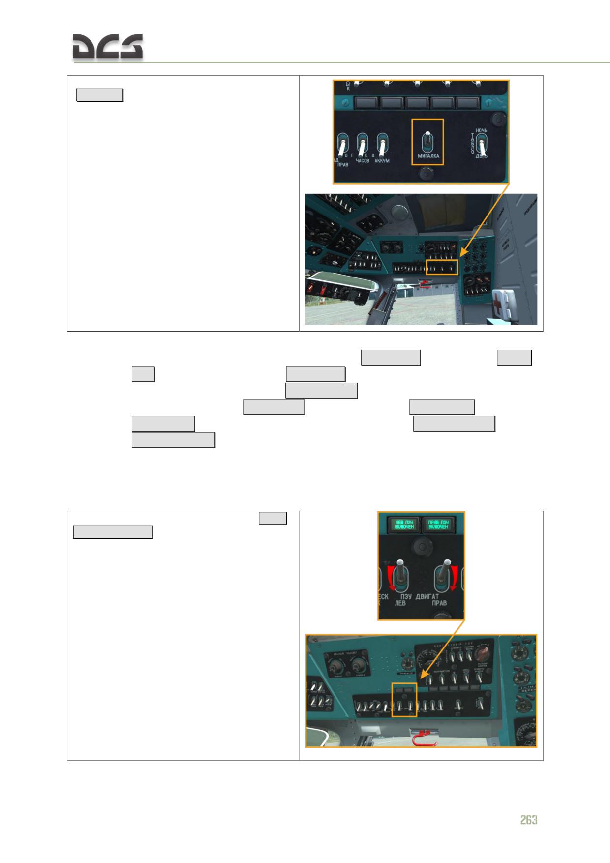
14. Enable the MIGALKA (FLASH) system
[RCtrl + -]
For night flights:
enable (if no before) the navigation lights
[RCtrl + 1]
(dimmed) or
[RCtrl
+ 2]
(bright), MSL-3 flasher
[RCtrl + 6] and rotor tip lights. If necessary,
turn on the formation lights [RCtrl + 3..4]
;
enable the taxi light
[ RCtrl + L]
and landing lights
[ LShift + L] (left),
[RShift - L] (right); lights can by controlled by the
[LShift + 9-;-0]
(left),
[RShift + 9-;-0]
(right), more in details in the chapter 7.8.1.
9.6. Engine shutdown
In preparation for idle power setting:
1. Switch off the PZU particle separators
[LCtrl
+ D] / [RCtrl + D]
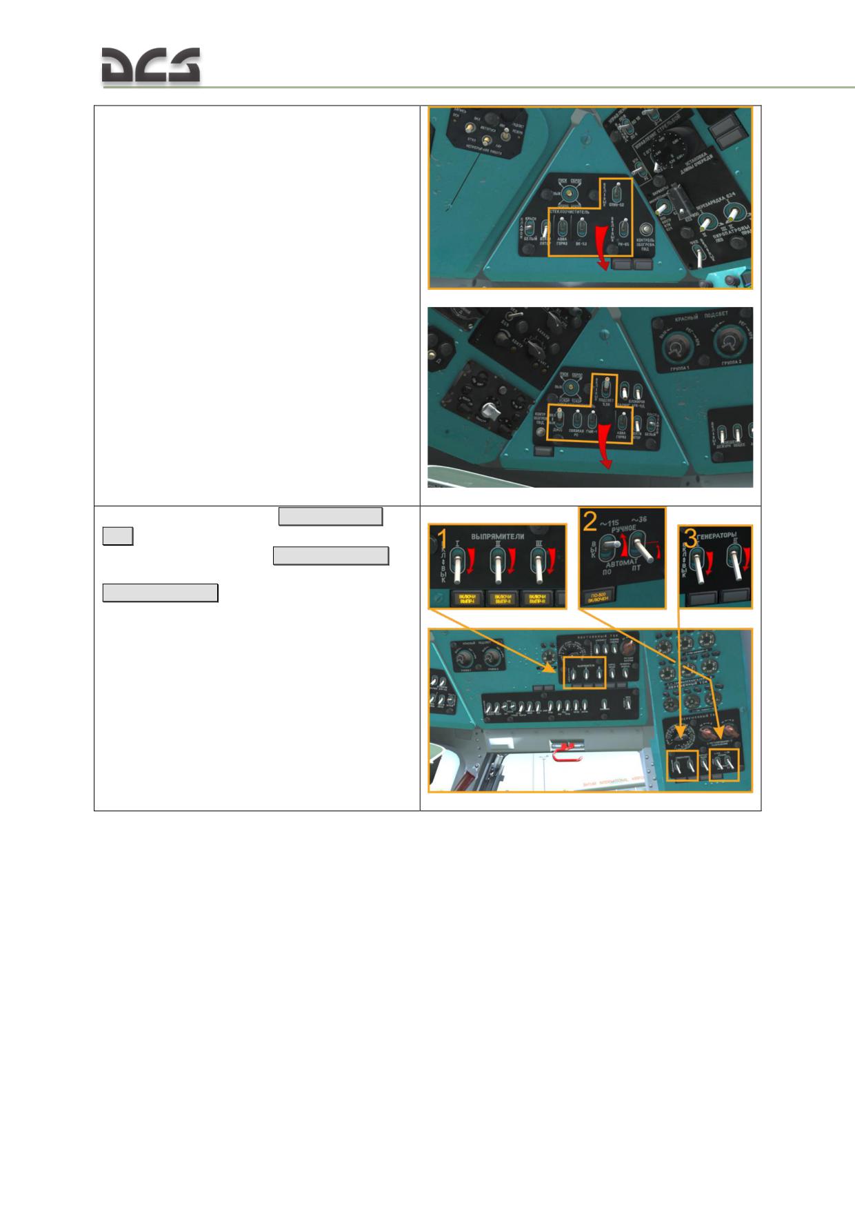
2. Switch off all electrical power consumers
apart from powerplant monitoring and control
systems (left and right side):
3. Switch OFF the rectifiers
[LCtrl + LShift +
4..6]
, set the "ПО-500А" (Inverter 1) switch to
"РУЧНОЕ" (MANUAL (up))
[LAlt + LShift + 4]
,
switch OFF the AC generators
[LAlt + LShift + 6]
264
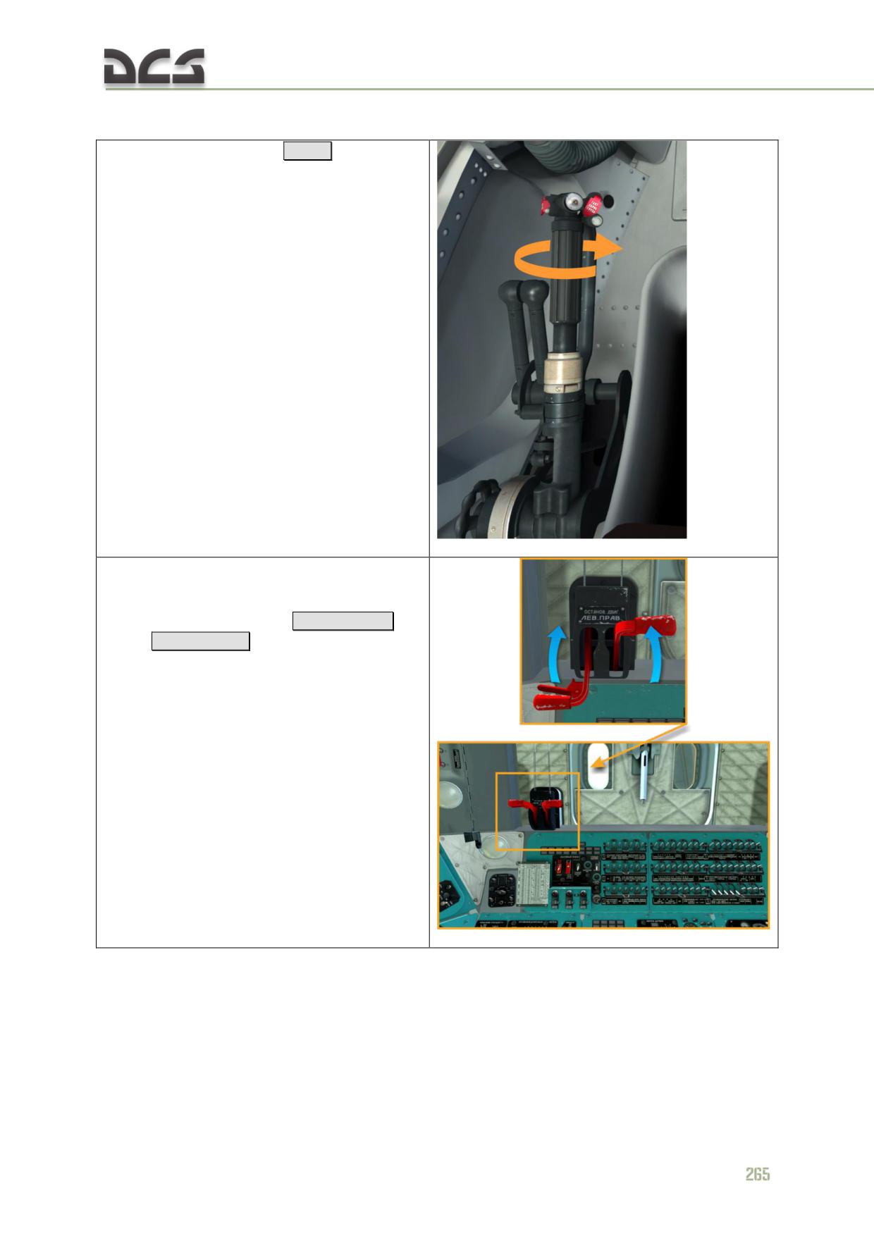
engines idle power and stop:
4. Turn the throttle full left
[PgDn]
and perform
the following steps:
5. After allowing the engines a 2 minute cool
down period in idle power, close (pull aft) the
"ОСТАНОВ. ДВИГ. ЛЕВ. ПРАВ." (ENGINE STOP
LFT/RGT) fuel shutoff levers
[ RCtrl + PgUp]
(left) /
[RCtrl + PgDn]
(right)

6. After Nr <15% - engage the rotor brake
[RCtrl + R]
7. With engines fully stopped, switch off the fuel
fire (shutoff) valves
[LAlt + 5..6]
(for cover up)
then
[RAlt + 5..6]
266
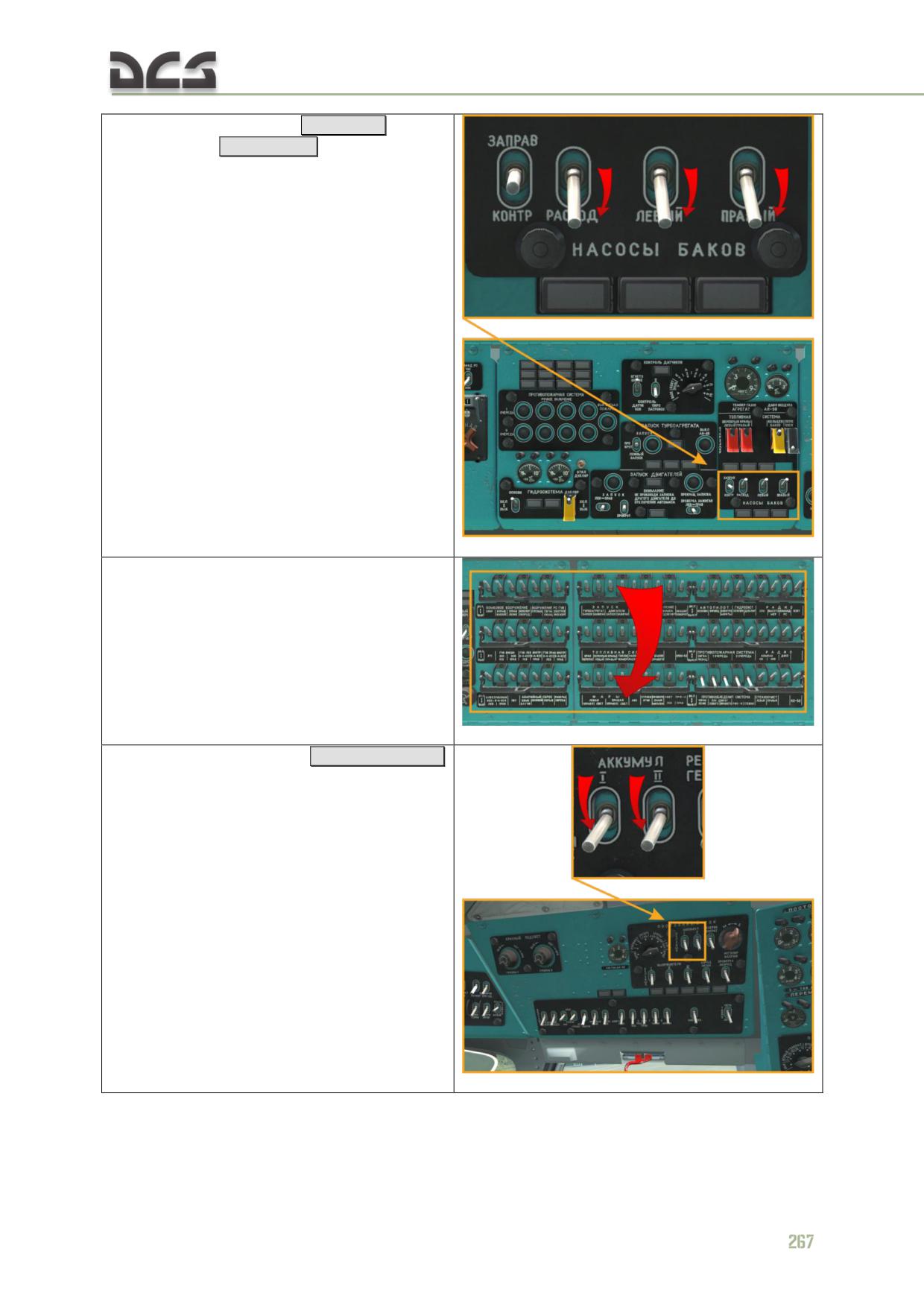
8. Switch off the fuel boost [RShift + 1]
and
transfer pumps
[RShift + 2..3]
9. Switch off all of the circuit breakers and set
all other control switches to OFF positions, apart
from the reserve hydraulic system
10. Switch OFF the batteries
[ LCtrl + LShift + 1]
11*. Set the "САРПП-12Д1М "РУЧН - АВТОМ"
(FLIGHT RECORDER) switch to the "АВТОМ"
(AUTO) position (down)
[LAlt + LCtrl + LShift + 6]
9.7. Preparing for taxi and taxiing
А. Prior to taxi, perform a taxi check:
external power cables are disconnected:
[\]
(Radio Menu),
[F8]
,
[F2]
,
[F2]
;
fuel pumps are on (check switch positions and indicator lights);
APU is shut down;
all circuit breakers are switched ON.
B. Check the taxiway is clear of obstructions and proceed to:
set throttle full right;
switch ON PZU particle separators;
check main rotor RPM to be within 95±2%;
request clearance to taxi;
release the wheel brakes [W]
Increase collective to set 1-2° of collective pitch and slightly push forward on the
cyclic to begin forward movement.
C. Maintain weight on wheels during taxi.
If the ground surface prevents safe taxiing, perform hover taxi using low speed/low
altitude flight.
D. Taxi speed should not exceed 15 - 20 km/h. Perform taxi turns using smooth
pedal input and small moving the Cyclic to side of turn. Avoid completely unloading
weight off the nose wheel shock strut.
E. Wind speed during taxi must not exceed 15 m/s. In crosswind conditions, the
helicopter tends to turn into the wind. Correct any uncommanded turning tendency
with slight opposite pedal and any uncommanded roll with slight opposite cyclic.
268
F. Upon reaching the takeoff position, check the flight and navigation indicators,
ensure the attitude indicator is powered up (no warning flag present), the heading
indicator shows correct bearing to the selected ADF beacon, and the compass set is
slaved and indicating correct takeoff heading.
Start the flight timer on the AChS-1 cockpit clock by pressing the left red knob
[RALT + RCTRL + RSHIFT + C]
9.8. HOVER
А. The following maximum hover altitude limitations apply depending on helicopter
gross weight (GW):
GW ≤ 11,100 kg: 10 m
GW > 11,100 kg: 5 m
Hover altitudes greater than above limitations are allowed when carrying external
sling loads or if dictated by tactical requirements.
B. Yaw rate in hover must not exceed 12°/sec.
C. To perform a hover:
position the helicopter into the wind if possible
check throttle set full right
smoothly increase collective to set collective pitch to 3°
check main rotor RPM to be 95%. If necessary adjust main rotor RPM
using the N2 TRIM INCR-DECR switch on the collective control handle
turn off the autopilot (all channel)
[LWin + LShift + A] and then turn on
the autopilot "КРЕН-ТАНГАЖ" (ROLL-PITCH)
[LWin + A]
channel by
pressing the corresponding button-lamps and checking for green light
illumination
continue to smoothly increase collective to lift the helicopter off the
ground and climb until reaching desired hover altitude
D. Increase of collective control during liftoff must be smooth and gradual, allowing
no less than 5 seconds for the engines to attain Takeoff power, ensuring main rotor
RPM is maintained within normal limits of 92 - 94%.
E. During liftoff, the helicopter tends to drift forward and left.
F. The cyclic control stick deflection in hover is approximately:
1/4 stick travel aft when helicopter CG is at normal to aft limit position;
1/2 stick travel aft when helicopter CG at the forward limit position
1/4 stick travel right regardless of CG position
9.9. Shifts and hops at low aititude
А. Shifts and hops at low aititude may be performed for training purposes, special
purpose operations, and in cases where the ground surface conditions do not allow
for safe ground taxi.
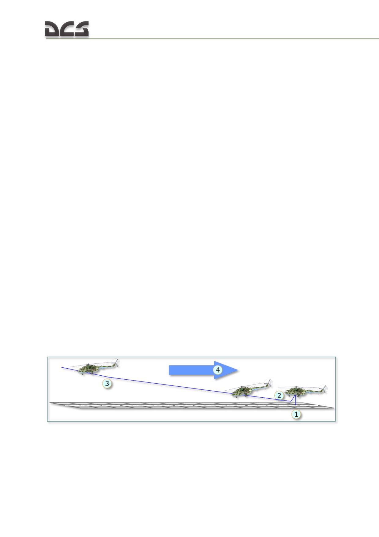
B. Lateral and reverse hover flight speed may not exceed 10 km/h. Use the ground
for visual reference and ensure that the flight path is clear of obstacles.
C. Forward hover flight altitude may not exceed 10 m and speed not exceed 20
km/h. Use the ground for visual reference and the stationary flight indicator of the
Doppler system for precise flight control.
With wind speeds of up to 10 m/s, shifts and hops at low aititude can be performed
into the wind or at 90° to the wind. With wind speeds greater than 10 m/s, hover
taxi should only be performed into the wind.
D. Perform low level flight over uneven terrain (gullies, ditches, drop-offs, etc.) at
altitudes of no less than 20 m and speeds no less than 60 km/h.
9.10. Takeoff
Takeoff is performed using one of the following procedures:
vertical takeoff with acceleration in ground effect
vertical takeoff with acceleration out of ground effect
running takeoff
running nose wheel takeoff
The minimum dimensions of the airfield required for a takeoff or landing at altitudes
of up to 1500 m are as follows:
50 x 50 m for a vertical takeoff/landing free of obstacles
50 x 120 m for a vertical takeoff/landing with an obstacle height of 15 m
at the airfield outer edge
50 x 160 m for a running takeoff/landing free of obstacles
50 x 200 m for a running takeoff/landing with an obstacle height of 15 m
at the airfield outer edge
Vertical takeoff with acceleration in ground effect
A vertical takeoff with acceleration in ground effect may be performed when the
helicopter hovers at an altitude of no less than 3 m with the engines set to Takeoff
power.
Fig. 9.1. Vertical takeoff with acceleration in ground effect
Position the helicopter into the wind (4) and perform a hover safety check to ensure
the helicopter is ready for takeoff (1). Confirm normal indicator readings and a
sufficient hover altitude for a vertical takeoff. Reduce altitude to 0.5-1 m (2) and
begin the takeoff by smoothly pushing the cyclic forward while simultaneously
270
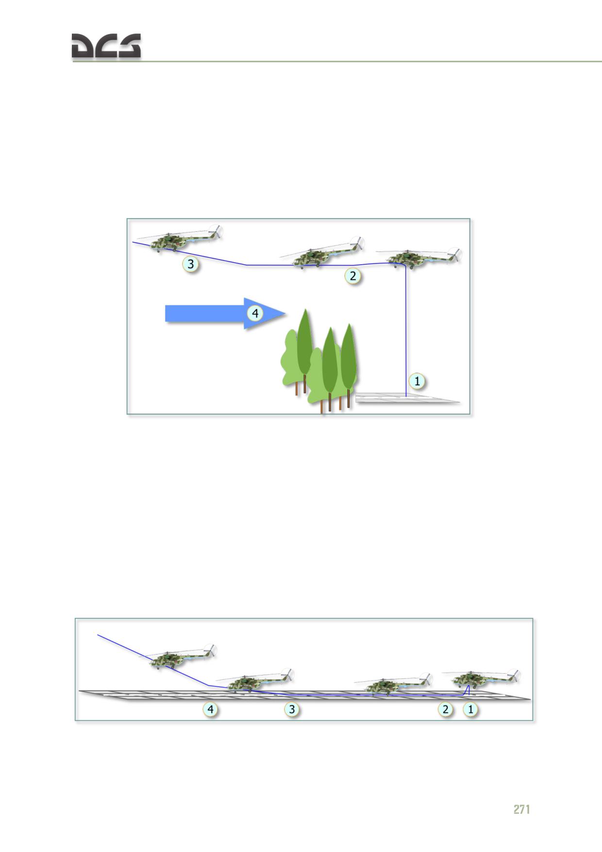
advancing power as required up to Takeoff setting to avoid main rotor RPM drooping
below 92%. Accelerate in ground effect in a shallow climb to reach 60-70 kph at an
altitude of 20-30 m (3). Transition to a climbout attitude while accelerating to 120
kph.
Vertical takeoff with acceleration out of ground effect
A vertical takeoff with acceleration out of ground effect must be performed when the
takeoff area is confined and surrounded with obstacles, and the helicopter’s takeoff
weight allows for a hover out of ground effect.
Fig. 9.2. Vertical takeoff with acceleration out of ground effect
Position the helicopter into the wind (4). Perform a vertical takeoff while minimizing
drift (1) to an altitude of at least 10 m above obstacle height. In the vertical climb,
monitor the main rotor RPM to ensure it does not droop below 92%. Having attained
a hover altitude sufficient for a safe transition to forward flight above obstacle
height, smoothly push the cyclic forward to accelerate up to 20-50 kph
(2).
Transition to a climbout attitude while accelerating up to 120 kph (3).
Running takeoff
A running takeoff may be performed if the helicopter hovers at an altitude of no less
than 1 m with the engines set to Takeoff power. For a running takeoff, only the
ROLL-PITCH channel of the autopilot should be engaged.
Fig. 9.3. Running takeoff
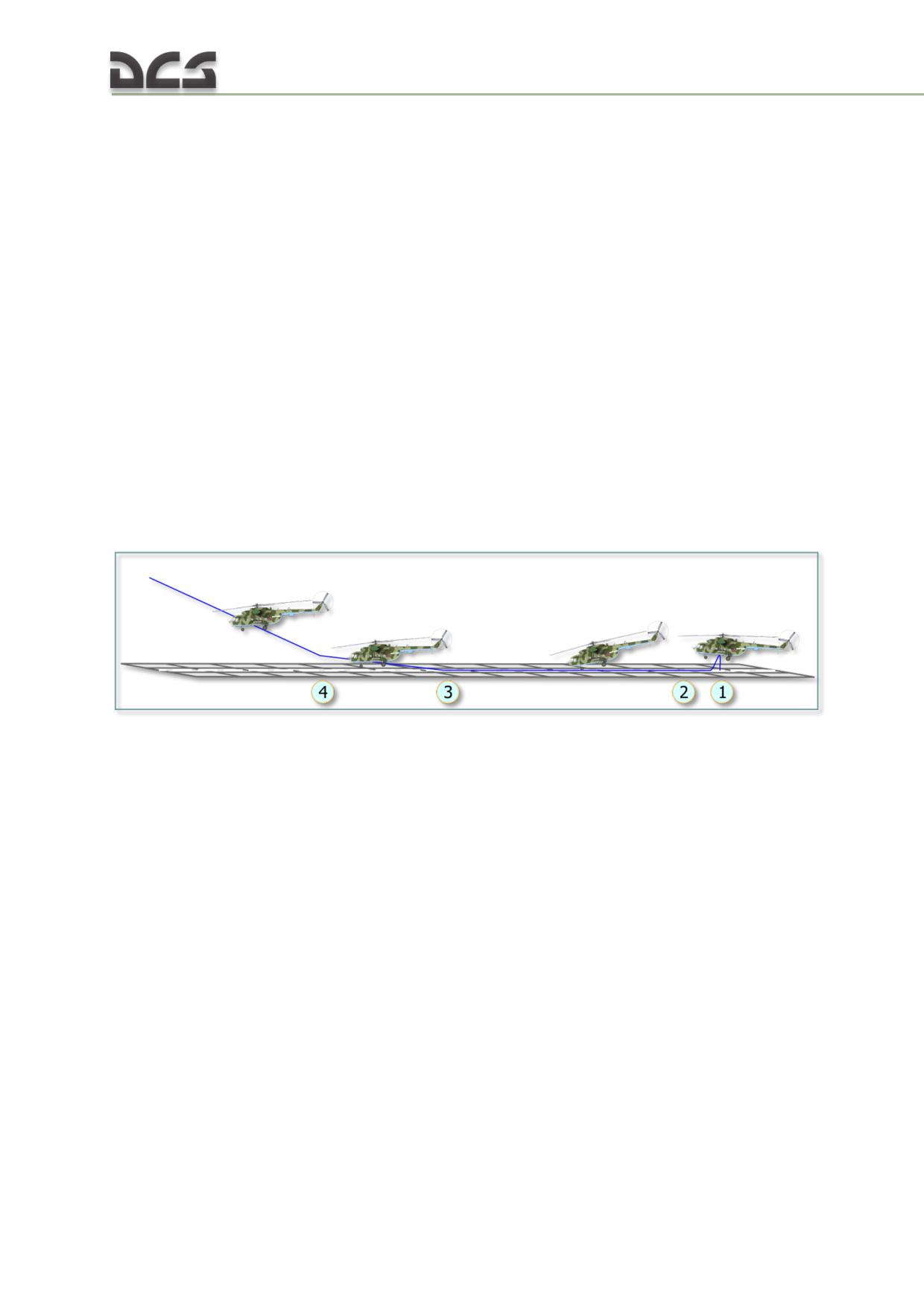
Perform a hover check then land the helicopter (1). Reduce collective until the
helicopter rests on the ground with weight on wheels.
Push the cyclic forward and simultaneously increase collective to establish forward
acceleration up to 20-50 kph (2). Increase collective further to attain Takeoff power
and lift the helicopter off the ground (3).
In the takeoff run, the helicopter tends to lift off the main wheels first, followed by
the nose wheel. Compensate for this tendency with slight pull aft of the cyclic at the
moment of liftoff.
After liftoff, continue to accelerate up to 120 kph in a shallow climb, followed by a
transition to a climbout attitude (4).
The takeoff run requires 250 - 300 m. If the takeoff area is limited or blocked by
obstacles, the transition to climbout can be made at 50 - 60 kph.
Running nose wheel takeoff
A running nose wheel takeoff may be performed to increase takeoff performance
with a high takeoff weight or to reduce the distance of the takeoff run on airfields
that provide for a safe ground run.
Fig. 9.4. Running nose gear takeoff
Perform a hover safety check then land the helicopter (1).
Disable the autopilot by pressing the AUTOPILOT OFF button on the cyclic control
stick. Reduce collective pitch to minimum by lowering the collective control handle to
the lower stop (full down). Apply the wheel brakes. Push the cyclic control stick to
the forward limit and proceed to turn ON the autopilot ROLL-PITCH channel by
pressing the corresponding button-lamp on the autopilot control panel and checking
for green light illumination. Pull the cyclic control stick to the aft limit and release the
stick force by pressing the TRIM button on cyclic control stick. The forward and aft
deflection limits of the cyclic are determined by the absence of thumping noise as the
main rotor blades strike against the flapping hinges of the rotor assembly.
Release the wheel brakes. Smoothly increase collective until the main landing gear
begins to lift off the ground. Maintain the nose gear on the ground. Smoothly (3 - 5
sec) push the cyclic forward 1/2 to 2/3 stick travel to begin the ground run and
establish a nose-down pitch attitude of -8 to -9° below standing pitch (2). Control
the pitch angle during the ground run by maintaining the blade tips of the rotor disc
on the horizon line. Smoothly increase engine power to Takeoff setting in the ground
run.
272
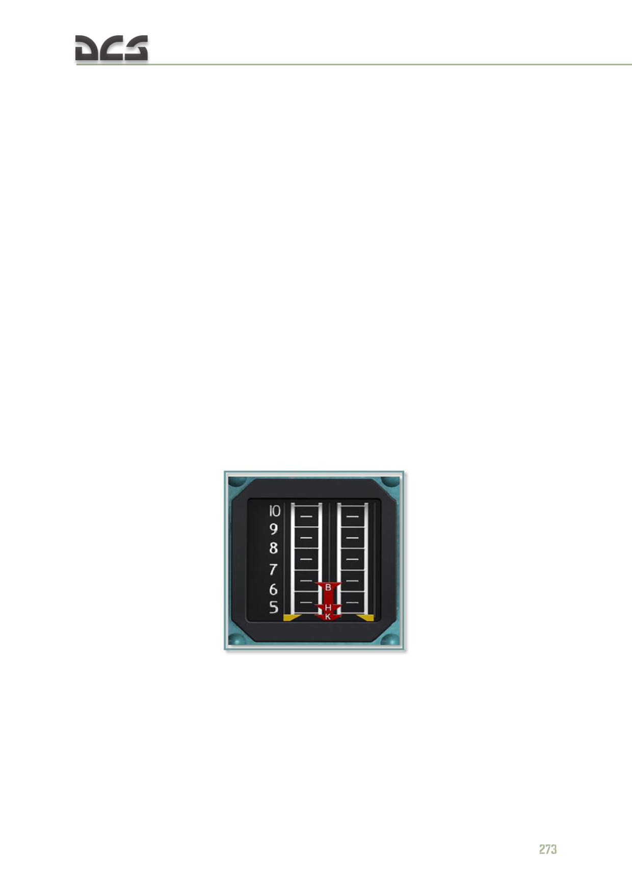
At approximately 40 kph the helicopter exhibits a tendency to pitch up and sink onto
the main gear, followed by a reversal and an energetic pitch down. These tendencies
must be countered with corresponding forward and aft cyclic control adjustments.
Lift off 1 - 2 seconds after the pitch down with a smooth cyclic pull aft as ground
speed reaches 60 - 65 kph (3). Continue to accelerate to 70 - 80 kph up to an
altitude of 10 m. Proceed with climbout at a speed of 120 kph (4).
With a maximum takeoff weight of 1300 kg, a ground run of 150 m is required for a
paved runway or 340 m for a field airstrip. If the helicopter’s CG is close to the aft
limit, the ground run distance increases by a factor of 1.5.
After leveling off at the desired altitude in stabilized in level flight, switch OFF the
autopilot by pressing the AUTOPILOT OFF button on the cyclic control stick, stabilize
the controls and switch ON the autopilot ROLL-PITCH and YAW channels by pressing
the corresponding button-lamps on the autopilot control panel and checking for
green light illumination.
9.11. Climb to altitude
А. The optimal climb speed is 120 kph in altitudes up to 2000 m; 110 kph in altitudes
of 2000 - 4000 m; and 100 kph above 4000 m. Climbs are normally performed in
maximum continuous engine power. If required, the climb may be performed in
Takeoff power (limited to 6 minutes) as well as power settings below maximum
continuous.
After completing the takeoff, establish the desired climb rate and switch OFF the PZU
particle separators.
Fig. 9.5. Engine pressure ratio (EPR) indicator
B. Current engine power setting is monitored on the engine pressure ratio (EPR)
indicator up to an altitude of 2500 m and is determined by the position of the side
indices with respect to the "Н" and "К" markers:
Takeoff power: side indices above "H"
Maximum continuous power: side indices above "K" up to "H"
Cruise power: side indices aligned with or below "K"
C. At altitudes greater than 2500 m, engine power setting is determined based on
corresponding performance charts.
D. In a climb at maximum continuous power with a constant collective pitch angle,
the main rotor RPM is automatically maintained at 95±2% up to a limited altitude.
Further climb will result in the main rotor RPM drooping as engine power output is
reduced due to compressor RPM limits imposed by the engine governor system.
Maintain main rotor RPM above 92% by gradually reducing collective pitch as main
rotor RPM begins to droop. The maximum continuous power limitations begin to
affect main rotor RPM at 1000 - 1500 m.
In a climb at cruise power with a constant collective pitch angle, the main rotor RPM
is automatically maintained constant up to an altitude of 2000 - 2500 m.
In a climb at takeoff power with constant collective pitch angle, the main rotor RPM
is not maintained automatically. Maintain main rotor RPM in the 92-94% range by
gradually reducing collective pitch as altitude increases.
9.12. Level flight
The recommended airspeed for flying an airfield pattern is 160 kph.
Roll angles are limited to 30° at normal takeoff weight and 20° at maximum takeoff
weight.
9.13. Transitional maneuvers
А. To transition from a vertical climb to a hover after reaching the desired altitude,
stop the climb by smoothly reducing collective and maintain altitude with slight
collective adjustments.
B. To transition from a hover to a vertical descent, reduce collective and ensure the
descent rate does not exceed 0.2 m/s near the ground prior to touchdown.
C. To transition from a hover to level flight, push the cyclic forward to establish an
accelerating attitude. Simultaneously adjust (slightly increase) collective to maintain
altitude and counter any lateral drift and yaw with opposite cyclic and pedal input.
When approaching the desired airspeed, pull the cyclic aft to stabilize in a level flight
attitude and maintain airspeed.
D. To transition from level flight to a hover while maintaining altitude, smoothly
reduce collective and pull the cyclic aft to reduce airspeed. Upon reaching airspeed of
50 - 60 kph, the helicopter exhibits a tendency to descend. Counter this tendency by
increasing collective.
At airspeeds below
50 kph, the helicopter develops
vibrations, which disappear as airspeed is reduced further. At airspeeds below 40 -
20 kph, the helicopter exhibits a tendency to yaw left. Timely application of cyclic
and right pedal input is required to avoid uncommanded roll and left yaw in the
transition to hover.
E. To transition from level flight to a power-on glide, reduce collective and apply
cyclic to establish a desired glide speed attitude.
274
F. To transition from a power-on glide to level flight, apply collective to set engine
power as required for level flight and apply cyclic to establish a desired airspeed.
G. In transitional maneuvering, the main rotor RPM is automatically maintained at
95± 2% only within a limited rate of collective application:
when increasing collective, no less than 5 seconds from 1 - 3° collective
pitch up to the pitch angle establishing takeoff power.
when reducing collective, no more than 1°/sec from any starting collective
pitch angle
Collective input rates above these limits can lead to main rotor RPM drooping below
the minimum allowable limit (88%) when increasing collective or overspeed the main
rotor above the maximum allowable limit (103%) when reducing collective.
If main rotor RPM runs outside 95±2%, adjust collective to return RPM to the normal
range.
Large deflections of the cyclic can lead to main rotor RPM drooping in accelerations
and increasing RPM in decelerations. The range of main rotor RPM divergence is
proportional to the rate of cyclic deflection.
When performing transitional maneuvers, unload the forces on the controls with
short presses of the TRIM button on the cyclic control handle as the flight controls
are adjusted.
9.14. Descent
Depending on altitude, power-on descent may be performed either vertically or on a
glideslope. Autorotation may only be performed on a glideslope descent.
Power-on vertical descent
A power-on vertical descent from am altitude of 10 m down to the ground is
permissible in all conditions. From an altitude of 110 m down to 10 m, a vertical
descent is only permissible when a glideslope approach cannot be performed due to
obstacles or out of tactical considerations. Descent from the helicopter’s service
ceiling down to 110 m must be performed on a glideslope and within airspeed
limitations.
In a vertical descent from an altitude of 110 m down to 10 m, the descent rate may
not exceed 3 m/s. If the descent rate increases beyond 3 m/s, smoothly increase
collective to arrest the descent rate. If engine power is insufficient to arrest the
descent and maintain main rotor RPM within limits, transition out of the vertical
descent to a glideslope descend or forward flight to gain airspeed.
From an altitude of 10 m down to the ground, continually reduce the rate of descent
so it does not exceed 0.2 m/s at touchdown.
Power-on gliding descent
In a power-on glideslope descent, maintain main rotor RPM within 95±2% with
collective input as required. Gradual reduction of collective pitch down to the
minimum setting is permissible to maintain a desired descent rate as altitude
decreases as long as main rotor RPM is maintained within limits.
The recommended glide speed at altitudes below 2000 m is 120 - 180 kph. The rate
of descent at this speed should be 3 - 5 m/s.
9.15. Autorotation descent
А. An autorotation descent is used in case of dual engine failure in flight. To perform
an autorotation landing:
establish a desired descent airspeed prior to initiating the descent
reduce collective down to the lower stop (full down) and check the main
rotor RPM to be within normal limits (95±2%)
counter the any tendency to yaw right and pitch down with opposite pedal
and cyclic
set throttle to full left
upon transitioning to an autorotation descent, adjust collective as required
to maintain main rotor RPM within limits
B. Maintain the following airspeeds in a power-on autorotation descent:
altitude 2000 m and greater: 100 - 120 kph
altitude below 2000 m: 120 - 190 kph
The optimum gliding speed for altitudes below 2000 m is 180-190 kph.
C. Maintain a descent rate of 10 - 12 m/s. The minimum rate of descent of 10 m/s
corresponds with a gliding speed of 120 kph.
D. Avoid roll angles of greater than 20° during autorotation descents.
E. To recover from a power-on autorotation descent:
smoothly set throttle to full right while monitoring the engine and main
rotor RPM
at altitudes above 1500 m, counter main rotor overspeeding beyond
maximum limits by increasing collective to set a collective pitch angle of 3
- 4°
at altitudes below 1500 m, increase collective pitch only after setting the
throttle to full right. Avoid drooping the main rotor RPM below 92% by
raising collective gradually
F. Maintain 100 - 120 kph in a power-off autorotation descent
9.16. Landing
Landing is performed using one of the following procedures:
vertical landing from a hover in ground effect
vertical landing from a hover out of ground effect
power-on running landing
single engine landing
power-off autorotation landing (only in emergency situations)
276
When performing any landing with forward airspeed, including autorotation landing,
disengage the autopilot YAW and ALTITUDE channels.
Vertical landing from a hover in ground effect
Perform a glideslope approach at 120 kph. At an altitude of 100 m, smoothly pull
the cyclic aft to begin reducing forward airspeed to attain 60 - 50 kph at an
altitude of 60 - 50 m.
At an altitude of 5 - 8 m, smoothly pull the cyclic further aft and increase
collective as required to establish a hover at a altitude of 2 - 3 m.
The minimum glideslope approach length:
with GW ≤ 11,100 kg is 1000 -1200 m at altitude of 100 m and
airspeed 100-120 kph
with GW > 11,100 kg is 1400 -1500 m at altitude of 100 m and
airspeed 100-120 kph
While performing the deceleration and transitioning to a hover, release the forces
on the controls with frequent presses of the TRIM button on the cyclic control
stick.
Upon stabilizing in a hover, smoothly decrease collective to perform a vertical
descent while gradually reducing vertical speed such that it does not exceed 0.2
m/s at touchdown.
Avoid lateral drifting while in the vertical descent. Reduce collective to minimum
only when certain that the helicopter is firmly on the ground with weight on
wheels.
In a crosswind landing, apply cyclic opposite of the wind direction to maintain
position over the landing point until the helicopter is firmly on the ground with
weight on wheels.
Vertical landing from a hover out of ground effect
Perform a vertical landing from a hover out of ground effect only when obstacles
make it impossible to perform a landing from a hover in ground effect.
The procedure for a vertical landing from a hover out of ground effect is identical
to a vertical landing from a hover in ground effect.
Begin the deceleration at an altitude of 50 m above obstacle height such that a
hover position over the landing point is attained at an altitude of no less than 5
m above obstacle height.
Power-on running landing
A power-on running landing may be performed in cases where engine power is
insufficient to ensure a hover and vertical landing (such as high gross weight, high
altitude, high temperatures).
The landing can be performed on a prepared runway or a an unprepared area known
to be safe for such an approach (must be sufficiently level and large) provided a
clear approach path is available.
Execute the final approach on a glideslope with an airspeed of 120 kph.
Maintain the glideslope such that airspeed is maintained 20 kph faster than current
altitude, i.e. 100 kph at 80 m down to an altitude of 40 m.
Perform the remainder of the descent with a continual reduction of airspeed and rate
of descent such that at 0.5 - 1 m above the ground, the airspeed is reduced to 50 -
40 kph and the rate of descent is reduced to 0.1 - 0.2 m/s.
Perform a smooth touchdown on the main gear and reduce collective to minimum.
Allow the nose gear to touch down. Set throttle to full left and apply the wheel
brakes to brake the helicopter. Anticipate a landing run of 20 - 30 m. The total field
distance for safe operations should be no less than 100 m.
If the airfield dimensions do not allow for a landing run of 20 - 30 m, but it is
necessary to perform a running landing, execute a running landing with a short
landing run.
Begin a smooth reduction of forward airspeed and rate of descent at an altitude of
40 - 50 m above the field by increasing collective and pitching the helicopter up with
aft cyclic while maintaining the main rotor RPM within allowed limits. Perform a
landing deceleration maneuver so as to attain near takeoff engine power at an
altitude of 5 - 10 m with a ground speed of 20 - 40 kph. At an altitude of 5 - 10 m,
push the cyclic forward to
bring the helicopter to a landing attitude while
avoiding a tail boom strike against the ground, but ensuring continued reduction of
ground speed down to 10 - 15 kph for touchdown. At an altitude of 5 - 10 m, raise
collective at a rate of 2 - 4°/sec to reduce the rate of descent such that it is no
greater than 0.2°/sec at touchdown. Upon touchdown, push the cyclic forward 1/3 -
1/4 stick travel, reduce collective down to minimum, set throttle to full left, and apply
the wheel brakes to brake the helicopter.
Single engine landing
Perform a single engine landing onto a flat landing area that provides for a clear
approach or onto a prepared runway. The gross weight of the helicopter for a single
engine landing may not exceed 10,000 kg.
Perform a single engine landing into the wind if possible or with a crosswind not
exceeding 5 m/s.
At an altitude of 300 m, before starting the APU, switch OFF the engine anti-icing
system and PZU particle separators if these were previously switched on. Start the
APU. Confirm successful APU start and illumination of the OIL PRESS NORMAL
(ДАВЛ. МАСЛА НОРМА), NORMAL SPEED (ОБОРОТЫ НОРМА) lights.
Execute a single engine landing so that the helicopter touches down at 10 - 20 kph
or 50 kph (as decided by the pilot in command) as follows:
control collective pitch to maintain main rotor RPM within 95±2%
278
ensure the operating engine attains emergency power setting
maintain an airspeed of 20 kph higher than current altitude (in meters)
during the approach
establish a landing attitude at an altitude of 5- 7 m
from an altitude of 3 - 5 m, reduce the rate of descent by increasing
collective. Simultaneously apply smooth right pedal to counter torque-
induced yaw from increased collective pitch and use cyclic control to
maintain the landing attitude. When increasing collective, ensure that
main rotor RPM does not fall under 88%
upon touchdown immediately decrease collective smoothly and push the
cyclic forward 1/3 - 1/4 stick travel to prevent a tail boom strike
apply wheel brakes after nose gear touchdown to brake the helicopter
Using this procedure the helicopter touches down at a speed of 10 - 20 kph and the
landing run is 5 - 20 m. To touch down at a speed of 50 kph, perform the approach
such that the airspeed is maintained 20 kph higher than current altitude down to an
altitude of 40 m, then maintain 60 km/h down to 5 - 7 m. Perform the touchdown as
described above, which results in a landing run of 80 - 100 m due to the higher
landing speed.
9.17. Search and Rescue (SAR) operations
А. Prior to departure for a SAR mission:
turn on the VHF ADF (РАДИОКОМПАС УКВ) circuit breaker on the right
circuit breaker panel of the overhead console.
on the VHF ADF (АРК - УД) control panel, set the mode selector switch to
NS (ШП), the frequency selector switch to VHF (УКВ), and the CHANNELS
(КАНАЛЫ) selector switch to 4.
on the intercom control box, set the selector switch to PK2 and the INT -
RADIO (СПУ-РАДИО) selector switch to RADIO (РАДИО)
fly the helicopter to enter the search area bearing in mind that the VHF
ADF (АРК - УД) detection and homing ranges increase with altitude (at an
altitude of 500 m the coverage is no less than 25 km)
with the ADF operating in standby reception mode, positive reception of a
beacon signal will be indicated by the corresponding indication light.
B. After detection and identification of the beacon signal, determine its location as
follows:
set the mode selector switch to a position corresponding to the indication
light: narrow band NB (УП) or broadband BB (ШП) if the NB light is on,
set the mode selector switch to NB
test the pointer arrow by pressing the ANT L (AHT. Л) or R (АНТ. П)
buttons to manually turn the arrow and make sure that it returns to the
signal bearing when the buttons are released
turn the helicopter so that the pointer arrow points to "0" and continue to
fly the helicopter to maintain the pointer arrow in this position. At long
ranges to the beacon, begin homing in narrow band NB (УП) mode. As
signal strength increases (indicated by increasing volume in the headset),
select the broadband BB (ШП) mode. The VHF ADF operation is more
reliable in broadband mode.
9.18. Flight (hover) over featureless terrain using the Doppler
Navigation System
А. The stationary flight indicator provides visual indication of the ground speed in the
following speed ranges: 0 - 50 kph in forward flight, 0 -25 kph in reverse flight, 0 -
25 kph in lateral flight.
B. The forward and lateral speeds are indicated by corresponding moving indexes
against a numerical scale (up and down for forward and reverse flight, left and right
for lateral flight). Vertical velocity is indicated by a moving triangular index along the
left side of the indicator.
Before takeoff, turn on the Doppler system by setting the DOPPLER (ДИСС) circuit
breaker on the overhead console and the DOPPLER (ДИСС) switch on the right
switch panel of the overhead console to ON (BKЛ).
C. When hovering, observe the indicators of the Doppler system. Apply cyclic control
opposite of the movement of the line indicators to maintain a hover position by
keeping the indicators inside the center ring position. Maintain the vertical velocity
indicator at “0” to maintain altitude.
In limited visibility conditions when the natural horizon cannot be seen, control the
helicopter’s attitude using the Attitude Indicator and other flight instruments. Control
hover altitude using the radar altimeter. The radar altimeter provides accurate
altitude indication up to 1000 m above ground level (AGL). If airspeed reaches 50
kph, the stationary flight indicator will turn off and the OFF (ВЫКЛ.) light will
illuminate.
9.19. Night operations in visual meteorological conditions
(VMC)
А. The start, ground test, and shutdown procedures for nighttime operations are
identical to daytime operations except the following: additionally turn on the LAND
LIGHTS (ФАРЫ), NAV LTS (АНО), FORM LIGHTS (СТРОЕВ. ОГНИ) and CHK BLINKER
(ПРОВЕРК. ЛАМП-МИГАЛКА) circuit breakers on the overhead console and set the
DOME LT RED - WHITE (ПЛАФОН КРАСНЫЙ - БЕЛЫЙ) selector switches to WHITE
(БЕЛЫЙ) on the left and right switch panels of the overhead console. Turn down the
red lighting rheostats on the left and right side panels of the overhead console and
the flight compartment doorway. Turn on ФР-100 taxi light.
B. After starting the engines and disconnecting the external electrical power source,
switch off the white dome lights, set the DAY - NIGHT (ДЕНЬ - НОЧЬ) selector
switch to NIGHT (НОЧЬ), and turn on the BLINKER
(МИГАЛКА),
ANTI-COLL
LIGHT (ПРОБЛЕСК) and BLADE TIP (КОНТУР. ОГНИ) switches. Set the navigation
and formation lights
switches to BRIGHT (ЯРКО) or DIM (ТУСКЛО) as desired.
280
Taxi with the ФР-100 taxi light on. Use the ФПП-7 landing/search lights only when
required for improved forward visibility or taxi turns. Limit operation of the ФПП-7
landing/search lights to 5 minutes followed by a 5 minute cooling period.
C. Take off with both the ФР-100 taxi and ФПП-7 landing/search lights turned on.
Adjust the direction of the light beams in a hover at an altitude of 3 - 5 m by
operating the corresponding switches on the collective control handle.
D. Accelerate and climb out to an altitude of 50 m more gradually than in daytime
operations. At an altitude of 30 - 50 m, transition to instrument flight and turn off the
taxi and landing/search lights.
E. For night time flying, refer primarily to the flight instruments with occasional
checking of the outside airspace.
F. Perform approach and landing maneuvers as during daytime operations. At an
altitude of 50 - 70 m, turn on the ФПП-7 landing/search lights. If the landing/search
lights make visual perception of the ground more difficult, turn the lights off and use
other light sources for ground reference, such as ground-based light projectors if
available. Use the radar altimeter to control altitude with visual ground checks using
available light source references.
After landing, taxi with the ФР-100 taxi light turned on.
9.20. Day or night operations in instrument meteorological
conditions (IMC)
А. Prior to embarking on any flight in IMC, carefully examine the weather conditions
in the area of operations, paying special attention to possible icing conditions, wind
speeds and directions. Flight inside clouds is permissible up to an altitude of 3500 m.
B. Before taxiing out, check that all circuit breakers and switches required for flight
are turned on and set correctly. Ensure normal operation of the autopilot control
channels, attitude indicators, turn indicators, ADFs, compass system, radar
altimeter, windshield wipers, and the Doppler system speed and drift
indication. Check that the clock is running and set for the correct time. The pressure
on the barometric altimeter should correspond to the actual airfield pressure when
the altimeter is set to 0 altitude. Check that the compass system is turned on and
operating normally, the setting of the latitude correction, selection of magnetic
compass (MK) mode, and the Doppler system is operating normally as indicated by
the FUNC (РАБОТА) light on the control panel.
C. For ambient temperatures of +5°C or below, turn on the pitot tube heaters before
taxiing out of the parking area and turn them off after taxiing to the parking area.
Before taxiing out of the parking area in ambient temperatures of +5°C or below,
turn on the engine anti-ice systems to prevent icing in the air intakes and ingestion
of ice into the engines by setting the ANTI-ICING SYSTEM. ENG DUST PR-LEFT and
ANTI-ICING SYSTEM. ENG DUST PR-RIGHT (ОБОГРЕВ. ДВИГ. ПЗУ ЛЕВ. (ПРАВ))
switches to ON (ВКЛ.).
D. Set the chart angle for the selected route on the coordinate indicator of the
Doppler system, set the range and angle error to 0, and turn off the control panel
using the OFF (ВЫКЛ.) button.
E. After taxiing to the takeoff position, slave the compass system, set heading
pointer of the heading indicator to the takeoff magnetic heading.
F. Request permission for takeoff from the controller. Upon receiving clearance,
proceed with takeoff. Maintain visual contact with the ground in hover.
G. After takeoff and before entering the cloud cover, establish a climbing profile at
an airspeed of 150 kph and a climb rate of 3 - 4 m/s. Transition to complete
instrument flight 25 - 30 m below cloud cover.
When flying in clouds, the following flight profiles are recommended:
climb speed of 150 kph at climb rate of 3 - 4 m/s
descent speed of 120 - 200 kph at rate of descent of 3 - 4 m/s
horizontal flight speed of 160 - 180 kph for a standard approach
Prolonged route flying at altitudes of up to 1000 m at the following airspeed:
220 kph at normal takeoff weight
200 kph at maximum takeoff weight
9.21. Wide rectangle pattern
The wide rectangle pattern is a convenient landing pattern when the approach to the
locator middle marker (LMM) is made within 60° of the magnetic landing course.
Perform an IMC approach and landing by referencing the LMM, which is positioned at
a distance of 1300 m from the landing point. The recommended pattern altitude is
300 m, airspeed is 160 kph, roll angle in turns is 10°.
If flying the pattern after takeoff, establish a climbing profile for an airspeed of 150
kph and a climb rate of 3 - 4 m/s.
Perform the first turn to the crosswind leg at an altitude of no less than 150 m at
distance of 3500 m from the reference startling line (runway takeoff position) or
when the calculated flight time for the initial leg has expired (1 min 32 sec in calm
weather). Upon reaching an altitude of 300 m, establish level flight at 160 kph. In a
missed approach or practice approach without landing, perform the first turn to the
crosswind leg 2 minutes after passing over the LMM.
Perform the second turn to the downwind leg when the LMM relative bearing (RB
(bearing from current heading to marker) equals 240° ± drift angle (DA) (120° ± DA
for a right-hand pattern) or upon reaching the required magnetic radio bearing
(MRB, bearing to marker from due North and indicated on the heading indicator
compass card by the bearing pointer) 3 min 27 sec after takeoff time.
Perform the third turn to the base leg when RB = 240° ± DA (120° ± DA for a right-
hand pattern) or upon reaching the required MRB.
On the base leg, descent at a rate of 2 - 3 m/s and establish an airspeed of 155 kph.
Descend to an altitude of 200 m.
282
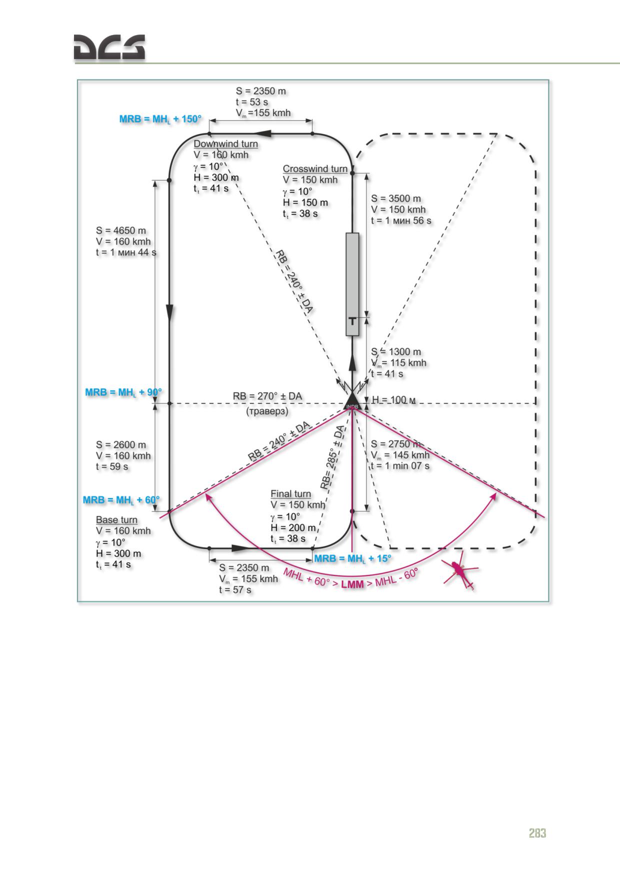
Fig. 9.6. Wide rectangle pattern diagram:
S - Distance
RB - NDB radio bearing
V - Airspeed
DA - Drift angle
H - Altitude
MRB - Magnetic radio bearing to beacon
- Bank angle
MHL - Magnetic landing heading
t - Time
FD - Flight direction
tt - Turn time
Perform the final turn in horizontal flight at an altitude of no less than 200 m at 150
kph. Initiate the final turn at RB = 285 ± SA (75° ± SA for right-hand pattern) or
upon reaching the required MRB.
Control the turn start and pattern leg flight times based on pattern calculations.
On the base leg nearing the fourth turn to final approach, the bearing needle of the
directional gyro will be moving toward the desired course needle (set to magnetic
runway heading). At the start of the turn, the angle between the desired course and
bearing needles should be 15°. When the turn is executed correctly, the two needles
will align approximately 30° prior to reaching final approach course.
Continue the final turn with the desired course and bearing needles aligned.
If during the first half of turn the angle between the bearing needle and the desired
course needle is constant or increasing, the angle of roll should be decreased. If
after the needles align the bearing needle starts falling behind the desired course
needle, the angle of roll should be increased, but by no more than 15°.
After recovering from the final turn, begin to descent at a rate of 2 - 3 m/s and
reduce airspeed to pass over the LMM at 100 - 140 kph at an altitude of 100 m. If an
altitude of 100 m is reached prior to passing over the locator middle marker,
transition to level flight.
If the final turn is recovered on a heading different from the landing course, perform
a course correction while on the descent by checking the course deviation angle
when the bearing needle is centered directly ahead to the LMM. If the difference
exceeds 5°, correct the heading error by turning toward the bearing needle (away
from the desired heading needle) such that the bearing needle is set midway
between the heading index on the compass card and the desired heading needle. If
the course indicator reads a magnetic heading exceeding the landing course, perform
the course correction to the right, otherwise perform the course correction to the
left.
After starting the course correction, maintain the corrective heading until the bearing
needle aligns with the desired heading needle, then turn the helicopter so as to align
the bearing needle and the desired heading needle on the landing course over the
compass card (or with an angle-off the landing course to account for drift).
In a right drift scenario, maintain the bearing and the desired heading needles
aligned along the landing course, but offset to the right along the compass card to
correspond to the drift angle.
Maintain the current landing course after passing over the LMM.
When flying the wide rectangle pattern for landing, maintain the landing course after
passing over the LMM and execute the first turn to the crosswind leg when the
calculated flight time has expired (2 min in calm weather).
9.22. Tight rectangle pattern
When the LMM is approached at an angle of greater than 60°, but less than 120° off
from the landing course, use the tight rectangle landing pattern.
284
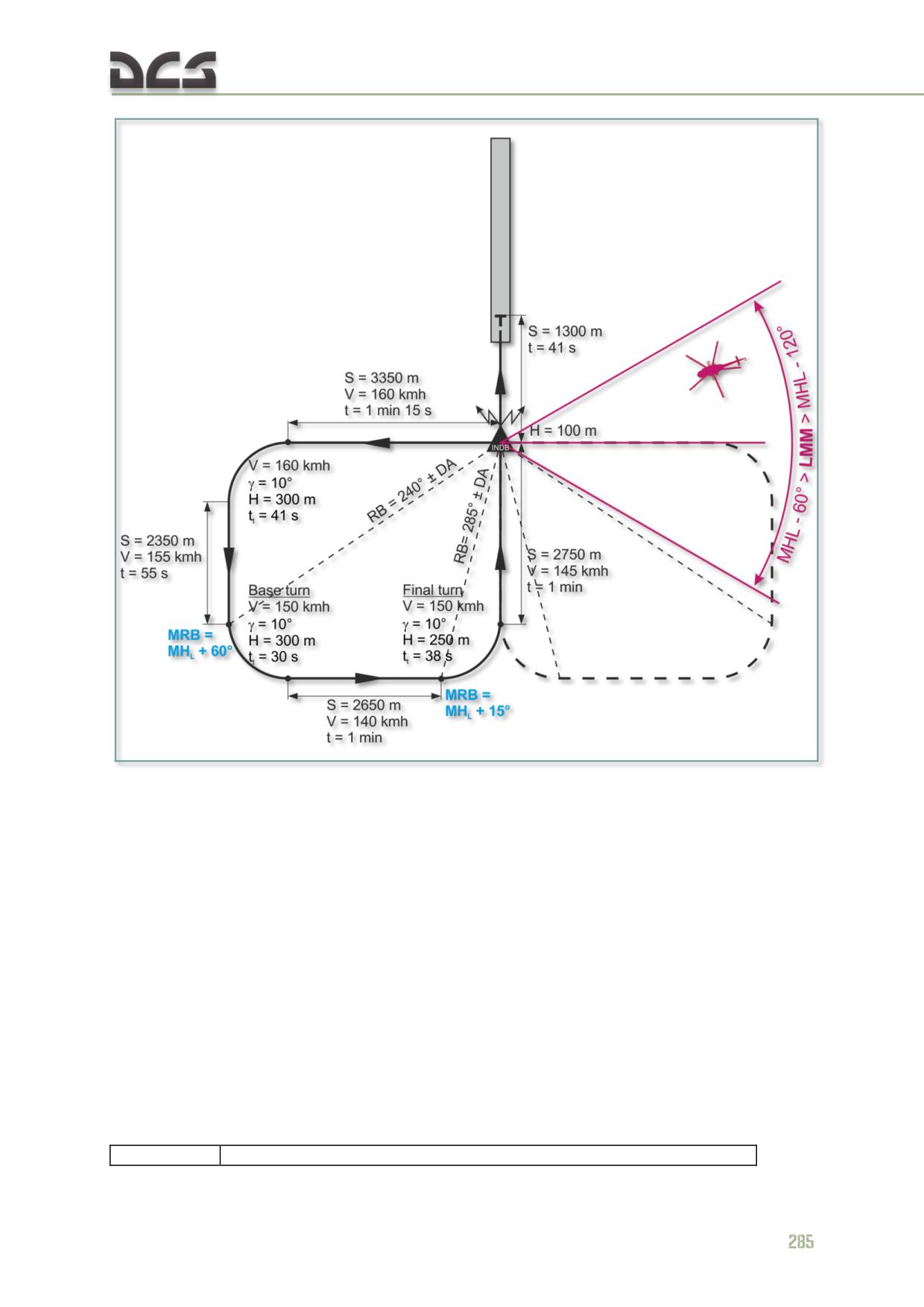
Fig. 9.7. Tight rectangle pattern diagram
After crossing the LMM, turn to a heading perpendicular to the landing (runway)
heading (estimating the drift angle). After the estimated time has been reached (1
min 15 sec for calm weather conditions), turn to a heading opposite the landing
heading and estimate the drift angle. Afterwards, the pattern is to be completed like
the big pattern approach.
9.23. Straight in approach with teardrop procedure turn
If the LMM is approached on a magnetic heading opposite to the landing course
(MHLO) or if the difference does exceed 60°, perform a straight in approach with a
teardrop procedure turn.
The magnetic heading, flight time (HFT), and estimated turn angle (ETA) calculations
for performing the teardrop procedure turn are prepared in advance taking into
consideration approach altitude and anticipated drift angles based on wind
conditions. The resulting values are entered into a reference chart:
Procedure
Н (altitude), m
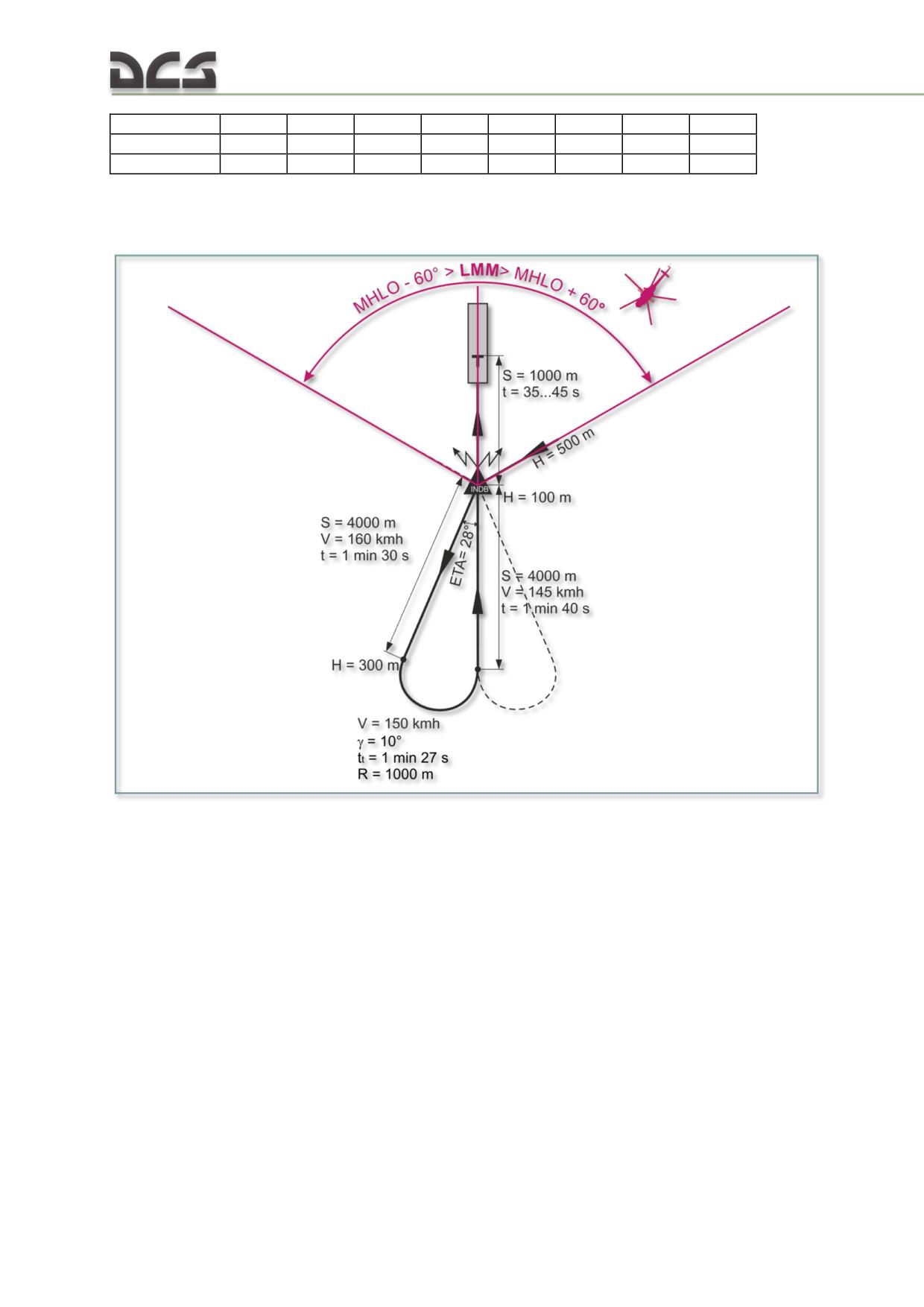
elements
300
400
500
600
700
800
900
1000
ETA, deg
28
19
14
12
10
8
7
6
HFT, min:sec
1:30
2:15
3:00
3:45
4:30
5:15
6:00
6:45
NOTE. chart assumes calm weather:
Vgs = 160 км/ч; V s = 2-3 m/s; AGS = 150 км/ч; = 10°
Fig. 9.8. Straight in approach with a teardrop procedure turn diagram
When performing a straight-in teardrop approach, navigate to the LMM at a selected
altitude. After passing the LMM, execute a right-hand or left-hand procedure turn
corresponding to the calculated turn angle (including drift calculation) and continue
flying on this heading until reaching the estimated turn to final approach position.
When the calculated horizontal leg flight time expires (HFT), proceed to descend at
an airspeed of 150 kph and a vertical speed of 2 - 3 m/s, turn to the landing course
with a roll angle of 10° and a descent of 200 m. In the final approach, compensate
for the drift angle, maintain the desired condition of flight and avoid sideslipping and
skidding. Having reached an altitude of 100 m, transition to horizontal flight, passing
the LMM at 100 m and an airspeed of 100 - 140 kph.
After breaking through the cloud cover, adjust the helicopter’s position on the
descent as required and proceed to land.
286
9.24. Special considerations for takeoff and landing operations
at high altitudes
The minimum field dimensions for a vertical takeoff or landing in ground effect with
no obstacles are 50 x 50 m. With a 15 m obstacle height, minimum dimensions for
the field depend on altitude as follows:
up to 1500 m: 50 x 120
2000 m: 50 x 165
3000 m: 50 x 255
3500 m: 50 x 300
4000 m: 50 x 345
The minimum field dimensions for a running takeoff or landing are:
up to 1500 m: 50 x 200
2000 m: 50 x 225
3000 m: 50 x 350
3500 m: 50 x 410
4000 m: 50 x 475
The minimum dimensions of a field for a single engine running landing at altitudes
up to 1500 m are 50 x 190 m if landing speed is 10 - 20 kph and 50 x 360 m if
landing speed is 50 kph.
Perform a vertical takeoff with acceleration out of ground effect in cases where the
field is of limited dimensions and surrounded with obstacles, and available engine
power is insufficient to allow a hover out of ground effect.
Perform a vertical landing with a hover out of ground effect when landing on a field
of limited dimensions at helicopter gross weights allowing a hover out of ground
effect.
Perform a vertical takeoff with acceleration in ground effect in cases where the
available engine power is sufficient to allow a hover at an altitude of no less than 3
m and the field dimensions allow for acceleration in ground effect.
Perform a vertical landing with a hover in ground effect in cases where the field
dimensions and approach paths, as well as the available engine power allow for a
deceleration and hover in ground effect.
Perform a running takeoff in cases where the available engine power is sufficient for
a hover at an altitude of no less than 1 m, and the field surface properties allow a
safe takeoff run over a distance of 80 to 100 m and subsequent acceleration in
ground effect.
Perform a running landing in cases where the field surface conditions and dimensions
allow for a safe execution of this procedure.
In a landing approach for a vertical landing in ground effect, plan the deceleration
such that the outer edge of the landing point is reached at an altitude of 2 - 3 m at 5
- 10 kph. Attempt to reach a hover position in the center of the landing point with
subsequent assessment of the ground surface and ideal touchdown point. If
necessary, approach the desired touchdown point at an airspeed of 5 - 10 kph.
In case of obstacles on the landing approach, plan the approach to allow a minimum
altitude of 10 m above obstacle height.
When performing an approach to deliver external sling cargo, plan and begin the
deceleration in advance. A high altitude approach with external sling load requires
1.5 - 2 times more distance than a low altitude approach. Aggressive deceleration
leads to more difficult flight control and load instability.
9.25. Takeoff and landing on an incline
Landing fields in mountainous terrain typically consist of inclines of various grades.
Incline grade limits for vertical takeoff and landing operations without engine
shutdown are:
nose up incline: 7°
nose down incline: 5°
left side up incline: 7°
right side up incline: 2°30'
Incline grade limits for vertical takeoff and landing operations with engine shutdown
are:
nose up incline/nose down incline/left side up incline: 3°
right side up incline: 2°30'
Vertical takeoff and landing on an incline in wind speeds up to 5 m/s are permissible
from any wind heading. In wind conditions above 5 m/s, vertical takeoff and landing
on an incline is permissible only into the wind and within above grade limitation
guidelines. Always attempt to perform takeoff and landing from an incline in either a
nose or right side up incline position. A nose up incline position is best.
When landing in a down incline position, hover at an altitude of no less than 3 m
above ground to avoid striking the tail boom on the ground. Descend to touchdown
strictly vertically and avoid any drift, in particular backward.
As the helicopter is hovered 3 m above ground, the height of the tail boom tip from
the ground is 0.6 - 0.8 m. At touchdown and liftoff, the height of the tail boom tip is
0.3 m. Aggressive deceleration just prior to achieving a hover position during landing
or excessive reduction of collective pitch may lead to the tail boom striking the
ground.
When descending to touchdown or taking off from an incline, keep the wheel brakes
depressed.
When landing on an incline in a position perpendicular to the slope, adjust cyclic in
the up slope direction to avoid drifting down slope. A hover over an incline is
maintained with some roll angle.
When lifting off from an incline in a position perpendicular to the slope, climb strictly
vertically and avoid any drift or yaw. As the helicopter lifts off, it will exhibit a
tendency to roll in the up slope direction, requiring opposite cyclic to compensate
and maintain position.
288
EMERGENCY
10
PROCEDURES
DIGITAL COMBAT SIMULATOR Mi-8МТV2
10.
EMERGENCY PROCEDURES
10.1. Single engine failure
Symptoms:
Uncommanded right yaw, the severity of which depends on the engine
power setting and airspeed at the moment of failure (the higher the
engine power setting and the lower the airspeed, the stronger the effect);
Drop of compressor RPM and EGT of the failed engine;
Increase of compressor RPM of the operating engine;
Drooping of main rotor RPM;
Illumination of the ЧР. ЛЕВ. (ПРАВ.) ДВ. (EMER PWR LFT (RGT) ENG)
light depending on the helicopter’s weight and altitude at the moment of
failure.
10.1.1. Crew actions in case of a single engine failure at an altitude above
100 m:
Reduce the collective pitch to maintain main rotor RPM no less than 92%;
Use cyclic and pedal control to correct uncommanded roll and yaw;
Accelerate or decelerate as required to an airspeed of 120 kph;
Determine which engine has failed by observing the instrumentation;
Order the crew chief to close the fuel shutoff lever and the fire valve of
the failed engine;
WARNING
When closing the fuel shutoff levers and fire valves, use extreme caution not to shut
down the operating engine!
Having reached an airspeed of 120 kph, operate the collective to set the
operating engine to a power setting sufficient to maintain level flight;
Make sure engine performance is adequate and sufficient to maintain level
flight. Navigate to the nearest airfield or find a suitable landing location;
Prior to landing, check the helicopter weight.
NOTE
1. In case of a single engine failure, the power setting of the remaining engine is
automatically increased by the electronic engine governor (EEG) system all the way
up to emergency power, depending on helicopter weight.
2. In case of EEG failure in flight, the remaining engine is not automatically set to
emergency power.
Crew actions if helicopter weight is under 12000 kg
Performing a gliding descent, maintain airspeed 20 kph higher than
current altitude until reaching an altitude of 40 m.
At an altitude of 40 m, begin to reduce airspeed by pulling the cyclic aft to
attain an airspeed of 40 kph at an altitude of 5 m with a vertical descent
rate of 2 - 3 m/s;
At an altitude of 5 - 7 m, establish a landing attitude;
From an altitude of 3 - 5 m, reduce vertical speed by increasing collective
pitch at a rate of 2 - 4°/sec. When increasing collective pitch, softly press
the right pedal to counter induced left yaw. Use the cyclic to maintain the
landing pitch angle. While increasing collective pitch, do not allow rotor
RPM to droop below 70%;
Land at a speed of 30 kph;
After landing, immediately proceed to smoothly lower collective to
minimum and simultaneously push the cyclic 1/3 - 1/4 travel forward to
prevent the main rotor blades from striking the tail boom.
After nose wheel touchdown, apply the wheel brakes.
Crew actions if helicopter weight is greater than 12000 kg
The following particulars must be taken into account:
The airspeed on the glideslope must be controlled such that 60 - 70 kph is
maintained as the helicopter reaches an altitude of 5 - 10 m;
Land at a speed of 50 kph;
Before landing, make sure the rotor RPM is no less than 88%.
NOTE
If at the moment of engine failure the airspeed is less than 120 kph and during
acceleration to an altitude of 10 - 20 m the helicopter does not reach sufficient
airspeed to allow level flight with a single engine operating in emergency power
setting, transition to a rapid vertical and forward deceleration to perform a landing as
described above.
10.1.2. Crew actions in case of a single engine failure at an altitude below
100 m
Reduce collective pitch to maintain rotor RPM no less than 92% and
ensure the remaining engine attains increased (emergency) power
setting;
Use cyclic and pedal control to correct uncommanded roll and yaw;
If airspeed is above 120kph, begin to decelerate and climb by increasing
helicopter pitch to 10 - 15°;
Determine which engine has failed by observing the instrumentation;
Order the crew chief to close the fuel shutoff lever and fire valves of the
failed engine;
Having reached an airspeed of 120 kph, operate the collective to set the
operating engine to a power setting sufficient to maintain level flight;
Make sure engine performance is adequate and sufficient to maintain level
flight;
When the airspeed is stabilized, navigate to the nearest airfield or find a
suitable landing location;
If at the moment of engine failure the airspeed is less than 80 kph, actions are as
follows:
Reduce collective pitch to maintain main rotor RPM no less than 92% and
ensure the remaining engine attains increased (emergency) power
setting;
Use cyclic and pedal controls to correct uncommanded roll and yaw;
Accelerate or decelerate as required to an airspeed of 40 - 60 kph,
depending on helicopter weight;
Begin to descend with a vertical speed not exceeding 3 - 4 m/s;
Descend to the chosen airfield;
Land.
10.2. Dual engine failure (Autorotation landing)
Symptoms:
Uncommanded right yaw, the severity of which depends on the airspeed
at the moment of failure (the higher the engine power setting and the
lower the airspeed, the stronger the effect);
Change in the cockpit sound of the powerplant;
Rapid drop of the main rotor RPM;
Drop of RPM and EGT of both engines.
10.2.1. Crew actions in case of dual engine failure at an altitude above
100 m:
Immediately reduce collective pitch to minimum;
Use cyclic and pedal control to correct uncommanded roll and yaw;
Close the engine fuel shutoff levers. Order the crew chief to close the fire
valves, turn off the boost and transfer pumps;
Accelerate or decelerate to reach the indicated glide speed of 100 - 120
kph;
Maintain main rotor RPM at maximum, i.e. 90 - 100% by observing the
indicator and adjusting collective control to avoid peaks over 110% and
droops under 88%;
Jettison all external payload in order to reduce weight;
Trim the helicopter to set a shallow dive, use cyclic control to counter the
rolling moment;
Find a suitable airfield and perform an upwind approach if possible;
If altitude allows, the approach can be adjusted using collective control
while maintaining rotor RPM within permissible limits;
At an altitude of 70 - 100 m, slightly and smoothly adjust cyclic control to
set and maintain a constant airspeed of 100 kph for a running landing or
70 kph for a vertical landing;
Starting from an altitude of 50 - 70 m, use the ground to visually gauge
and control altitude above the landing point. Use cyclic control to maintain
helicopter pitch;
292
Starting from an altitude of 10 - 15 m for a running landing or 15 - 20 m
for a vertical landing, increase collective pitch to 7 - 8° (perform a flare
within approximately 1 sec) and maintain it for 0.5 - 1 sec. If this is not
sufficient to reduce the vertical speed, increase collective pitch to 12°
(within 1 - 1.5 sec) to reduce vertical speed further;
During the flare and with a collective pitch increase rate of 10°/sec,
increase the pitch angle to 5 - 6° in order to reduce forward airspeed for a
running landing or to 8 - 10° for a vertical landing. Maintain the pitch
angle by slightly pushing the cyclic forward;
After landing, set collective pitch to 7 - 8° and maintain it until the landing
run is complete and the helicopter is stopped;
Pull back the cyclic to maintain the required pitch angle during landing
until nose gear touchdown, then smoothly push the cyclic forward 1/3 -
1/4 travel and apply the wheel brakes.
NOTE
1. If the selected landing field is off course from the flight path or the approach heading must be
changed due to wind conditions, perform the required maneuver (provided sufficient altitude is
available).
2. For an autorotation landing with a 180° turn (with a roll angle of 15°) altitude must be at least
650 m.
10.2.2. Crew actions in case of dual engine failure at an altitude of 100 m
and below
If the airspeed is close to 70 kph at the moment of dual engine failure, immediately
reduce collective pitch to maintain rotor RPM of 90 - 100%. Set a gliding speed of 70
kph for a running landing or as described above for a flare maneuver for a vertical
landing in case of a dual engine failure at an altitude above 100 m. After touchdown,
during the landing roll, order the crew chief to close the fuel shutoff levers and fire
valves, switch off the boost and transfer pumps, and turn off all electrical power;
If the airspeed is more than 120 kph at the moment of dual engine failure,
immediately reduce collective pitch to maintain main rotor RPM of 88% and
simultaneously decelerate by setting helicopter pitch up to 20° depending on
airspeed and altitude (the greater the airspeed and the lower the altitude, the higher
the pitch angle) above which the engines had failed. Increase collective pitch to keep
main rotor RPM under 110%.
Close the fuel shutoff levers of both engines. Use cyclic and pedal control to correct
any uncommanded roll and yaw.
If altitude allows for a quick deceleration to 70 kph, balance the helicopter at this
speed, then follow the above recommendations. If altitude is insufficient, maintain
helicopter pitch until ready to flare (fast pitch-up) at an altitude of 15 - 20 m.
If both engines fail in a hover, crew actions are the same as in the case of a single
engine failure, but keep in mind that in a hover, yaw instability, drop of main rotor
RPM, and transition to an uncontrolled descent are more abrupt due to the high
engine power settings required for hover.
CAUTION
In case of dual engine failure, a safe landing can be performed only on a firm and
level surface. Landing in any other conditions may cause damage to the helicopter.
10.3. Onboard fire
Symptoms:
Illumination and flashing of red fire lights ПОЖАР (FIRE) on Left
Instrument Panel;
Illumination and flashing of red fire lights ПОЖАР ЛЕВ. ДВ. (FIRE LFT
ENG) or ПОЖАР ПРАВ. ДВ. (FIRE RGT ENGINE), ПОЖАР К0-50 (FIRE
КO-50) or ПОЖАР РЕД. ВСУ (FIRE XMSN/APU), depending on where
the fire has been detected;
Presence of smoke, fire (not implemented in simulation);
Illumination of the amber light I ОЧЕРЕДЬ (1ST/MAIN DISCH)
corresponding to the compartment where a fire has been detected, upon
automatic initiation of discharge of the first extinguisher.
10.3.1. Crew actions in case of onboard fire:
а) In case of fire in the left (right) engine:
Close the fuel shutoff lever of the affected engine;
Order the crew chief to close the fire valve of the left (right) engine and
confirm that the first fire extinguisher has been automatically discharged;
Abort the mission and find an airfield to land.
WARNING
After the fire has been extinguished, attempting to restart the affected engine is
prohibited.
b) In case of a gearbox or APU fire:
If the APU is operating, shut it down;
Confirm that the first fire extinguisher has been automatically discharged.
c) If the automatic system fails (the I ОЧЕРЕДЬ
(1ST DISCH) light is not
illuminated), engage it manually by pressing the РУЧНОЕ ВКЛЮЧЕНИЕ I
ОЧЕРЕДЬ (MANUAL 1ST DISCH) button for the corresponding compartment.
If the fire has been eliminated, then within 10 seconds from the moment of the first
discharge the ПОЖАР ЛЕВ.ДВ (FIRE LFT ENG) (or ПОЖАР ПPAВ.ДВ. (FIRE RGT
ENG), ПОЖАР КО-50 (FIRE KO-50), ПОЖАР РЕД. ВСУ (FIRE XMSN/APU) -
depending on where the fire has occurred) lights will go off while the I ОЧЕРЕДЬ
(1ST/MAIN DISCH) light will remain on confirming that the first extinguisher has been
discharged.
If the fire has not been eliminated by the first discharge (the ПОЖАР ЛЕВ ДВ.
(FIRE LFT ENG) or ПОЖАР ПРАВ. ДВ. (FIRE RGT ENG), etc. light remains on),
manually initiate the second discharge by pressing the РУЧНОЕ ВКЛЮЧЕНИЕ II
ОЧЕРЕДЬ (MANUAL 2ND DISCH) button for the corresponding compartment.
294
If the first discharge eliminated the fire, but left signs of fire in another
compartment, press the РУЧНОЕ ВКЛЮЧЕНИЕ II ОЧЕРЕДЬ (MANUAL 2ND
DISCH) for the corresponding compartment.
NOTE
To turn off all electrical power:
Set the ГЕНЕРАТОРЫ
1,
2 (GENERATOR 1, 2) switches to neutral (center
position);
Turn the switches АККУМУЛЯТОРЫ 1.2 (BATTERY 1, 2) to ОТКЛ. (OFF);
If the СТГ-3 starter generator is ON, set the РЕЗЕРВ ГЕНЕР (STBY GEN) switch to
ОТКЛ. (OFF).
CAUTION
After eliminating of fire, abort the mission. If the fire persists, start immediate
landing with a parachute (depending on the situation)
- not implemented in
simulation.
10.4. Engine Malfunction
10.4.1. Automatic Control System Malfunction
There are two types of Engine Automatic Control System Malfunctions.
Type 1: N1 split of 2% or more, 3% at maximum power with temp regulator
operating, and/or engine power fails to change during collective movement with Nr
stable at 95 ± 2%.
1. Land as Soon As Practical
Type 2: N1 split greater than 2% with spontaneous increase of Nr above 95 ±2%.
If on takeoff or final approach:
1. Smoothly rotate throttle to left and increase collective to maintain 95 ± 2%
Nr.
For other phases of flight.
1. Increase collective to maintain 95 ± 2% Nr.
2. Determine malfunction by moving collective down then up (maintain Nr <
98%). Resulting engine indications determine what procedures to follow:
Case 1: N1 varies in both engines, Nr maintains 95 ± 2%.
o
1. Maintain 55-80 KIAS (100-150 kph)
o
2. Land as Soon as practical
Case 2: N1 varies in one engine, other engine at takeoff power, Nr
maintains 95 ± 2%.
o
1. Reduce ECL of engine at takeoff power
o
2. Maintain 55 - 80 KIAS (100-150 kph)
o
3. Land as Soon as practical
Case 3: N1 varies in one engine, other engine at take off power, Nr does
not maintain 95 ± 2%. (increases as collective is lowered and droops as
collective is raised)
o
1. Adjust throttle to maintain 95 ± 2% Nr
o
2. Maintain 55 - 80 KIAS (100 - 150 kph)
o
3. Land as Soon as practical
10.4.2. Abnormal Engine Vibration
Engine vibration is a signigicant indicator of potential catastrophic engine failure.
Verify which of the following indications are applicable and respond accordingly
A. Indications:
1. Amber HI VIBE light is illuminated
2. Red SHUT DOWN ENGINE light is illuminated.
B. Procedure:
1. HIGH VIBE LFT/RGT ENG Light On
o a. Monitor engine
o b. continue with mission
2. SHUT OFF LFT/RGT ENG Light On
o a. Reduce power
If light goes out:
o b. Establish 70 - 75 KIAS (130-140 kph)
o c. Land as soon as practical
If light stays on:
o d. Shut down engine (If you do not, possible engine fire after 30s )
o e. Refer to Single Engine Failure Procedure (10.1)
10.4.3. Low Engine Oil Pressure
If oil pressure is between 2-3 kgf/cm2:
o
1. ECL - Reduce (Affected engine)
o
2. Engine oil pressure - Monitor
o
3. Land As Soon As Practical
If oil pressure drops below 2 kgf/cm2 or oil temp exceeds 150°C:
o
1. Shut down engine
o
2. Refer to Single Engine Failure Procedure
10.4.4. Failure of electronic engine governor (EEG) power turbine
channels
Symptoms:
296
Illumination of the yellow ПРЕВ.nст ЛЕВ ДВ. (HIGH N2 LFT ENG) or
ПРЕВ. nст ПРАВ ДВ (HIGH N2 RGT ENG) light on the left instrument
panel;
the engine does not shut down.
Crew actions:
Temporarily switch off the EEG of the affected engine;
Check the ПРЕВ.nст ЛЕВ. (ПРАВ.) ДВ. (HIGH N2 LFT (RGT) ENG) light
to extinguish;
Switch on the EEG;
If the EEG light does not illuminate after resetting the EEG, check engine
operation indicators for normal readings and if no further faults are found,
continue the mission paying particular attention to the engine
performance parameters;
If the EEG light illuminates once again and remains on, abort the mission
and land at the nearest airfield, paying particular attention to the engine
performance parameters.
10.4.5. Failure of electronic engine governor (EEG)
Symptoms:
Illumination of the ОТКЛ.ЭРД ЛЕВ ДВ. (GOV OFF LEFT ENG) or
ОТКЛ.ЭРД ПРАВ.ДВ. (GOV OFF RGT ENG).
Crew actions:
Switch OFF the failed EEG;
Continue the mission paying particular attention to engine performance
parameters.
With a failed (switched off) EEG, the compressor RPM must not exceed
102.5%.
10.5. Main/Intermediate/Tail Rotor Gear Box Malfunction
Main Transmission Malfunction or Failure Main transmission malfunctions normally
procede catastropic failure. Early failure indications may very, depending on the
nature of the problem and the severity of failure. If a malfunction is encountered,
begin immediate decent at 70 - 75 KIAS and execute either a vertical or roll-on
landing as soon a possible. Indications and actions to be taken in the event of a main
transmission malfunction are as follows:
INDICATIONS:
Unusual Noise or Shaking of Aircraft
Transmission Oil Temperature above normal range (see Table 8.8)
Transmission CHIP light illuminated
Transmission Oil Pressure below normal operating range
Transmission Oil Pressure warning light illuminated.
Malfunctions in the drive line can be experienced in either the electornic
synchronisation system or as a mechanical problem in any of the dynamic
components. Nr irregularities, vibrations, oil over temperature or excessive main
gearbox pressure are the basic indications of drive line problems.
10.6. Yaw contol failure
Symptoms:
If the tail rotor or its transmission are damaged in flight, the helicopter
exhibits an abrupt left yaw, right roll, and negative pitch.
Crew actions:
Immediately reduce collective pitch and, if altitude is sufficient, order the
crew to eject from the helicopter.
If altitude is not sufficient for the crew to eject, crew actions are:
o Begin an autorotation descent; maintain heading by setting a roll angle
to the side opposite of the turning tendency;
o Balance the helicopter with sideslip as required; compensate the yaw
moment with lateral cyclic control;
o Find an airfield to land;
o Shut down the engines by closing the fuel shutoff levers;
o Close the fire valves, close the boost and transfer pumps (if possible);
o Perform an autorotation landing. Before landing, set a zero roll attitude
for touchdown.
If the actuator of the tail rotor is operative, but the cockpit controls are damaged
(the helicopter does not respond to pedal inputs), establish an airspeed of 120 - 130
kph, adjust collective as required to establish level flight or a shallow descent and
proceed to an airfield that can be used for a safe landing. Balance the helicopter with
sideslip as required. Execute a running landing. It is PROHIBITED to increase
collective pitch before touchdown to avoid unbalancing the helicopter.
If yaw control fails in hover or while moving at low altitude, crew actions are:
Immediately smoothly reduce collective pitch and descend to touchdown;
During the descent, press the right pedal and deflect the cyclic to the right
to counter left turn and left drift; pull the cyclic aft to counter the negative
pitch;
At the moment of touchdown by the main wheels, immediately and rapidly
minimize collective pitch and shut down the engines.
10.7. Hydraulic system failure
10.7.1. Failure of main hydraulic system
Symptoms:
The red ДУБЛИР.ВКЛЮЧЕНА (B/U SYS ON) light on the center
overhead console illuminates and starts flashing while the ОСНОВН.
ВКЛЮЧЕНА (MAIN SYS ON) extinguishes;
298
The pressure in the main hydraulic system drops down below 42 kgf/cm2,
while the pressure in the backup hydraulic system grows up to 42 - 73
kgf/cm2.
Crew actions:
Set the ОСНОВН ГИДРОСИСТЕМА (MAIN HYD) switch to to ВЫК
(OFF).
NOTE
Switching to the backup system disengages the AP-34B autopilot and the collective
clutch release system. In this case, collective handle friction force can be adjusted
manually using the friction hand wheel (not implemented in simulation).
Disengage the autopilot by pressing the autopilot disconnect button on
the cyclic control stick;
Abort the mission. With a particular attention to the hydraulic system,
perform landing in the nearest airport or onto a chosen airfield.
10.7.2. In case of failure of both main and backup hydraulic systems
Eject from the helicopter (not implemented in model).
10.8. Uncommanded left yaw during takeoff or landing
10.8.1. During a hover check before takeoff
Symptoms:
The helicopter does not respond to right pedal input up to full deflection
and continues to yaw left;
Main rotor RPM droops below the lower limit due to a sharp increase of
collective pitch angle.
Crew actions:
Immediately decrease collective pitch by 1 - 2° to counter uncommanded
roll and pitch;
Disengage the SPUU-52 tail rotor pitch limit system;
Descend to touchdown;
At the moment of touchdown rapidly lower collective to minimum and
order the crew chief to shut down the engines, close the fire valves, and
turn off all electrical power.
10.8.2. During a hover before landing
Symptoms:
The helicopter does not respond to right pedal input up to full deflection
during final deceleration to hover prior to landing and continues to yaw
left;
Main rotor RPM droops below the lower limit due to a sharp increase of
the collective pitch angle during final deceleration to hover prior to
landing;
While turning, the helicopter loses altitude with uncontrollable evolutions
in roll and pitch.
Crew actions:
In a hover at an altitude below 10 m
Immediately decrease collective pitch by 1 - 2° to counter uncommanded
roll and pitch;
Disengage the SPUU-52 tail rotor pitch limit system;
Descend to touchdown;
At the moment of touchdown rapidly lower collective to minimum and
order the crew chief to shut down the engines, close the fire valves, and
turn off all electrical power.
In hover at an altitude above 10 m
While applying full right pedal, quickly decrease collective pitch by 1 - 2°
and simultaneously push the cyclic forward and left to correct
uncommanded roll and pitch angles; transition to forward flight;
Disengage the SPUU-52 tail rotor pitch limit system;
Execute a go-around;
Repeat the landing approach and perform a running landing.
10.9. Vortex ring state (VRS)
The helicopter is susceptible to VRS in a vertical descent of greater than 3 m/s or in
a powered glide with a forward airspeed of less than 40 kph and a vertical speed of
more than 4 m/s.
Symptoms:
Uncommanded rapid increase of vertical speed;
Abrupt attitude changes and severe vibrations;
Loss of flight control effectiveness;
Unstable readings of airspeed and vertical speed indicators.
Crew actions:
Push the cyclic forward to establish a nose-down pitch of -10 to -20°,
increase collective to set engine power up to takeoff setting and begin to
transition into forward flight while avoiding drooping main rotor RPM
below 92%;
Having reached an airspeed of 60 - 80 kph, transition to level flight.
NOTE
1. A transition out of a vortex ring state to level flight may require 50-200 m of
altitude loss, depending on:
initial forward speed at the moment of entry into VRS;
the vertical descent rate at the moment of exiting VRS;
300