Mi-8MTV2 Magnificent Eight. PC flight simulator manual (2016) - page 1
TABLE OF CONTENTS
TABLE OF CONTENTS
1
IMPORTANT NOTICE!
9
1.
MI-8 HISTORY
11
2.
GENERAL DESIGN AND PURPOSE
19
2.1.
HELICOPTER DIMENSIONS
19
2.2.
PERFORMANCE SPECIFICATIONS
20
2.3.
PURPOSE AND MISSIONS
21
3.
HELICOPTER AERODYNAMICS
24
3.1.
GENERAL PRINCIPLES
24
Forces acting on a helicopter
24
CONTROLS
26
Velocity
26
Torque
27
Anti-torque rotor (tail rotor)
27
Gyroscopic precession
28
Dissymmetry of lift
28
Retreating blade stall
29
Settling with power (Vortex Ring State)
31
Hover
33
Ground effect
33
Translational lift
34
Autorotation
35
Summary
38
3.2.
MI-8MTV2 AERODYNAMIC PARTICULARS
38
Power requirement for level flight
39
Main rotor thrust
39
3.3.
MI-8MTV2 PERFORMANCE PARTICULARS
40
Safe altitudes and airspeeds in case of a single engine failure in flight
40
3.4.
MI-8MTV2 CONTROL PARTICULARS
40
3.5.
MI-8MTV2 TRIMMING AND BALANCING
41
Ground trim
41
Helicopter tendencies at liftoff
42
Roll TRIM
42
Yaw TRIM
42
Trimming in turns, spirals, and coordinated sideslips
43
3.6.
MI-8MTV2 STABILITY PARTICULARS
43
3.7.
MI-8MTV2 MANEUVERING PARTICULARS
44
Acceleration in level flight
44
Deceleration in level flight
44
4.
POWERPLANT AND DRIVE SYSTEM
46
4.1.
ENGINES AND RELATED SYSTEMS
46
4.1.1.
Air Inlet Particle Separator System ("PZU")
49
4.1.2.
Engine Anti-Ice System
50
4.1.3.
Engine Fuel System
50
Starting Fuel Flow
50
Steady State Operation
50
Temperature Limiter System Operation
50
Compressor Control System Operation
51
Engine Governor Operation
51
Engine Shutdown
52
Fuel Supply Switches
52
1
Power Controls
52
Engine Power Synchronizers
54
4.1.4.
Engine Oil System
54
Description
54
4.1.5.
Ignition-starting system
55
4.1.6.
Engine Trim Control
56
4.2.
AUXILIARY POWER UNIT
56
4.3.
DRIVE SYSTEM
58
4.4.
AIR COOLING SYSTEM
60
5.
COCKPIT SYSTEMS AND CONTROLS
63
5.1.
COCKPIT LAYOUT
64
5.1.1.
Left Instrument Panel (Pilot)
65
5.1.2.
Right Instrument Panel (Copilot)
67
5.1.3.
Center Console
68
5.1.4.
Left Side Console
69
5.1.5.
Left Triangular Panel
70
5.1.6.
Left Overhead Console
71
5.1.7.
Center Overhead Console
72
5.1.8.
Right Overhead Console
73
5.1.9.
Circuit Breaker Consoles
74
5.1.10.
Right Triangular Panel
75
5.1.11.
Right Side Console
76
5.1.12.
Right Rear Console
77
5.1.13.
Right Auxiliary Panel
78
5.2.
FLIGHT CONTROLS
79
5.2.1.
Cyclic Control System
79
5.2.2.
Directional Control System
80
Tail rotor pitch limit system
81
Directional control system failure in flight
82
5.2.3.
Collective Pitch Control System
83
5.3.
POWERPLANT AND HELICOPTER SYSTEMS CONTROLS AND INDICATORS
85
5.3.1.
ИТЭ-2Т (ITE-2T) Dual engine tachometer
85
5.3.2.
ИТЭ-1Т (ITE-1T) Main rotor tachometer
85
5.3.3.
ЭМИ-3РИ (EMI-3RI ) Engine oil pressure/temperature gauge
86
5.3.4.
ЭМИ-3РВИ (EMI-3RVI) Three pointer drive system oil pressure/temperature gauge .86
5.3.5.
2УТ-6К (2UT-6K) Power turbine inlet temperature (PTIT) gauge
87
5.3.6.
ИР-117 (IR-117) Engine pressure ratio (EPR) indicator
88
5.3.7.
ТУЭ-48 (TUE-48) Main transmission oil temperature gauge
89
5.3.8.
ТВ-19 (TV-19) Cargo cabin temperature gauge
89
5.3.9.
ТСТ-2 (TST-2) APU exhaust gas temperature (EGT) gauge
89
5.3.10.
УИ1-3 (UI1-3) APU air pressure gauge
90
5.3.11.
УИ1-100 (UI1-100) Hydraulic pressure gauges
90
5.3.12.
УП-21-15 (UP-21-15) Rotor pitch indicator
91
5.3.13.
СКЭС-2027В (CKES-2027B) Fuel quantity gauge
91
5.3.14.
ИВ-500Е (IV-500E) Engine vibration monitor
91
5.3.15.
МВУ-100К (MVU-100K) Pneumatic system pressure gauge
92
5.3.16.
МА-6К (MA-6K) Brake pressure gauge
93
5.4.
FLIGHT DATA AND NAVIGATION SYSTEMS CONTROLS AND INDICATORS
93
5.4.1.
Pitot static system
93
5.4.2.
УС-450К (US-450K) airspeed indicator
95
5.4.3.
ВД-10К (VD-10K) pressure altimeter
95
5.4.4.
ВР-30МК (VR-30MK) vertical speed indicator (VSI)
97
5.4.5.
АГБ-3К (AGB-3K) attitude indicator
97
5.4.6.
ЭУП-53 (EUP-53) Turn and Slip indicator
99
5.4.7.
ГМК-1А (GMK-1A) gyromagnetic compass set
100
5.4.8.
КИ-13К (KI-13K) magnetic compass
102
2
5.4.9.
АЧС-1 (AChS-1) clock
103
5.4.10.
ВК-53РШ (VK-53RSh) gyro correction cutout switch
105
5.4.11.
G-load indicator
106
6.
RADIO COMMUNICATION AND NAVIGATION SYSTEMS
108
6.1.
RADIO COMMUNICATION SYSTEMS
108
6.1.1.
СПУ-7 (SPU-7) intercommunications set (ICS)
108
Features of the "СПУ-РАД" (ICS-RADIO) switch
109
6.1.2.
Р-863 (R-863) VHF/UHF command radio set
110
6.1.3.
ЯДРО-1А (YaDRO-1A) HF radio set
112
6.1.4.
Р-828 (R-828) LVHF FM transceiver set
115
6.1.5.
РИ-65 (RI-65) audio warning system
118
6.2.
RADIO NAVIGATION SYSTEMS
119
6.2.1.
АРК-9 (ARK-9) automatic direction finding (ADF) set
120
6.2.2.
АРК-УД (ARK-UD) VHF homing set
123
6.2.3.
ДИСС-15 (DISS-15) doppler navigation set
128
6.2.4.
РВ-5 (RV-5) radar altimeter set
136
6.2.5.
Special purpose radio systems (UV-26 EW countermeasures system)
138
Components
138
УВ-26 (UV-26) control panel
139
7.
SYSTEMS OF HELICOPTER
142
7.1.
ELECTRICAL POWER SUPPLY SYSTEM
142
7.1.1.
Primary Power Sources
142
7.1.2.
Secondary Power Sources
144
Single-Phase 115 VAC System
144
Single-Phase 36 VAC System
144
27 VDC System
144
7.1.3.
Electrical Power Supply System Control
145
DC Power Control
146
AC Power Control
147
7.1.4.
Normal operation
148
7.1.5.
Failures
148
7.2.
FUEL SYSTEM
150
7.2.1.
Fuel Storage Location
151
7.2.2.
Fuel Distribution System
151
Function of Fuel System Units
153
7.2.3.
Monitoring and Control of Fuel System Operation
155
Fuel System Units Control
155
Fuel System Operation Monitoring
156
7.2.4.
Normal Operation
157
Before Start
157
Operation in Flight
158
7.2.5.
Failures
158
Failure of service fuel cell float valve (not implemented)
158
Failure of One/Both Transfer Pump
159
Service fuel cell Backing Pump Failure
159
7.3.
HYDRAULIC SYSTEM
160
7.3.1.
Brief Description
160
Main Hydraulic System
161
Backup Hydraulic System
161
Control of Hydraulic Systems
161
7.3.2.
Normal Operation
163
Check before starting the engine
163
During Engine Start
163
Hydraulic System Check During Power Plant Warm-up
164
7.3.3.
Failures
164
7.4.
ANTI-ICE SYSTEM
165
3
7.4.1.
General Description
165
7.4.2.
Heated Glasses
165
Wipers
166
7.4.3.
Anti-Ice System of air inlet Particle Separator System
167
7.4.4.
Rotors Anti-Ice System
171
7.4.5.
Ice Detectors
172
7.4.6.
Control of Anti-Ice System
173
7.4.7.
The effect of Anti-Ice System system on the flight characteristics
176
Maximum takeoff weight
176
Fuel consumption
176
7.5.
PNEUMATIC SYSTEM
176
Normal Operation
179
7.6.
FIRE PROTECTION SYSTEM
179
7.6.1.
Brief Description
179
7.6.2.
Fire detection and alarm system
180
Fire detection system
180
Fire alarm system
181
7.6.3.
Indication and alarm system check
183
7.6.4.
Fire extinguishing system
185
7.6.5.
Normal Operation
186
Operating Conditions (stages) and required actions
186
The system operation and crew procedure with fire protection equipment in case of fire
187
7.7.
ENVIRONMENTAL AND HEATING SYSTEM
188
7.7.1.
Brief description
188
7.7.2.
Enabling the KO-50 heater in automatic mode
191
7.7.3.
Enabling the KO-50 heater in manual mode
191
7.7.4.
Using the KO-50 heater in ventilation mode
191
7.7.5.
Switching OFF the KO-50 heater
191
7.8.
LIGHTING EQUIPMENT
192
7.8.1.
Exterior lighting equipment
192
FPP-7M search/landing light
193
FR-100 taxi light
196
MSL-3 anti-collision light
196
Navigation lights
197
OPS-57 Formation lights
199
Blade tip lights
200
7.8.2.
Interior lighting equipment
200
Cockpit illumination
200
Illuminaton of cargo cabin and technical compartments
205
In-helicopter light signalization system
205
7.9.
REGISTRATION OF THE FLIGHT PARAMETERS AND VOICE RECORDING
208
7.9.1.
SARPP-12DM flight data recorder
208
7.9.2.
P-503B voice recorder
210
7.10. SLING LOAD EQUIPMENT
211
7.10.1.
General description
211
7.10.2.
Cargo hook controls
212
Automatic opening
213
Manual cargo release
213
7.11. АП-34Б (AP-34B) AUTOPILOT SYSTEM
214
7.11.1.
General description
214
AP-34B autopilot system specifications:
215
7.11.2.
Autopilot system’s unit
215
7.11.3.
Autopilot controls and indicators
216
Control panel
216
ИН-4 (IN-4) zero indicator
217
7.11.4.
Equipment interacting with the autopilot system
218
7.11.5.
Use of autopilot in different flight phases
219
7.11.6.
Explanations of the AP-34B peculiarities and key commands
220
4
Combined operation of hydraulic boosters and the AP-34B autopilot in case of manual control
220
Game peculiarities, when pedals are used and "НАПРАВЛЕНИЕ" (YAW) channel is engaged
221
Trimmer features when autopilot is engaged
221
Positions of Cyclic and zero indicators on IN-4 during Hover and Level fligh (Roll-Pitch channel)
222
AP-34B Key Commands
224
7.12. EXHAUST IR SUPPRESSION DEVICES
224
8.
OPERATING LIMITS AND RESTRICTIONS
227
8.1.
CALCULATING MAXIMUM TAKEOFF WEIGHT
227
8.2.
CALCULATING FLIGHT RANGE, RADIUS, AND TIME
231
8.3.
ENGINES AND TRANSMISSION LIMITS
235
8.3.1.
Engines limits
235
8.3.2.
Transmition limits
238
9.
NORMAL PROCEDURES
240
9.1.
PREFLIGHT COCKPIT CHECK
240
9.1.1.
Simplified procedure
240
9.1.2.
Full procedure
241
9.2.
PREPARATION AND EQUIPMENT CHECK PROCEDURES PRECEDING APU START
242
9.2.1.
Simplified procedure
242
9.2.2.
Full procedure
244
Connection of power supplies
244
Equipment preparation and check procedures, continued
246
9.3.
STARTING THE APU AND MAIN ENGINES
246
Final procedures before APU start
247
Starting the AI-9v APU
248
Starting the TV3-117VM Main Engines
251
Immediately after starting the engine
254
9.4.
ENGINES WARM UP, FLIGHT CONTROLS AND HYDRAULIC SYSTEMS CHECKS
255
9.5.
ENGINE RUN UP, SWITCHING ON GENERATORS AND RECTIFIERS. AVIONICS CHECKS
256
А. Switching ON generators and rectifiers
256
B. Avionics check
260
9.6.
ENGINE SHUTDOWN
263
In preparation for idle power setting:
263
engines idle power and stop:
265
9.7.
PREPARING FOR TAXI AND TAXIING
268
9.8.
HOVER
269
9.9.
SHIFTS AND HOPS AT LOW AITITUDE
269
9.10.
TAKEOFF
270
Vertical takeoff with acceleration in ground effect
270
Vertical takeoff with acceleration out of ground effect
271
Running takeoff
271
Running nose wheel takeoff
272
9.11. CLIMB TO ALTITUDE
273
9.12. LEVEL FLIGHT
274
9.13. TRANSITIONAL MANEUVERS
274
9.14. DESCENT
275
Power-on vertical descent
275
Power-on gliding descent
275
9.15. AUTOROTATION DESCENT
276
9.16. LANDING
276
Vertical landing from a hover in ground effect
277
Vertical landing from a hover out of ground effect
277
Power-on running landing
277
Single engine landing
278
9.17. SEARCH AND RESCUE (SAR) OPERATIONS
279
9.18. FLIGHT (HOVER) OVER FEATURELESS TERRAIN USING THE DOPPLER NAVIGATION SYSTEM
280
9.19. NIGHT OPERATIONS IN VISUAL METEOROLOGICAL CONDITIONS (VMC)
280
9.20. DAY OR NIGHT OPERATIONS IN INSTRUMENT METEOROLOGICAL CONDITIONS (IMC)
281
5
9.21. WIDE RECTANGLE PATTERN
282
9.22. TIGHT RECTANGLE PATTERN
284
9.23. STRAIGHT IN APPROACH WITH TEARDROP PROCEDURE TURN
285
9.24. SPECIAL CONSIDERATIONS FOR TAKEOFF AND LANDING OPERATIONS AT HIGH ALTITUDES
287
9.25. TAKEOFF AND LANDING ON AN INCLINE
288
10.
EMERGENCY PROCEDURES
290
10.1. SINGLE ENGINE FAILURE
290
10.1.1.
Crew actions in case of a single engine failure at an altitude above 100 m:
290
10.1.2.
Crew actions in case of a single engine failure at an altitude below 100 m
291
10.2. DUAL ENGINE FAILURE (AUTOROTATION LANDING)
292
10.2.1.
Crew actions in case of dual engine failure at an altitude above 100 m:
292
10.2.2.
Crew actions in case of dual engine failure at an altitude of 100 m and below
293
10.3. ONBOARD FIRE
294
10.3.1.
Crew actions in case of onboard fire:
294
10.4. ENGINE MALFUNCTION
295
10.4.1.
Automatic Control System Malfunction
295
10.4.2.
Abnormal Engine Vibration
296
10.4.3.
Low Engine Oil Pressure
296
10.4.4.
Failure of electronic engine governor (EEG) power turbine channels
296
10.4.5.
Failure of electronic engine governor (EEG)
297
10.5. MAIN/INTERMEDIATE/TAIL ROTOR GEAR BOX MALFUNCTION
297
10.6. YAW CONTOL FAILURE
298
10.7. HYDRAULIC SYSTEM FAILURE
298
10.7.1.
Failure of main hydraulic system
298
10.7.2.
In case of failure of both main and backup hydraulic systems
299
10.8. UNCOMMANDED LEFT YAW DURING TAKEOFF OR LANDING
299
10.8.1.
During a hover check before takeoff
299
10.8.2.
During a hover before landing
299
10.9. VORTEX RING STATE (VRS)
300
11.
ARMAMENT SYSTEMS
303
11.1. EXTERNAL WEAPON STATIONS
305
11.2. CIRCUIT BREAKERS AND SWITCHES OPERATING WEAPONS INDICATION AND CONTROL SYSTEMS
305
11.3. PILOT'S UPPER AND LOWER ARMAMENT CONTROL PANELS
307
11.3.1.
Upper armament Control Panel
307
11.3.2.
Lower armament Control Panel
309
11.4. BOMBS CONTROL PANEL
312
11.5. ЭСБР-3П/А (ESBR-3P/A) ELECTRICAL RELEASE CONTROL BOX
314
11.6. PKV COLLIMATING SIGHT
315
11.7. WEAPONS FIRE AND BOMB RELEASE SWITCHES
320
11.8. AKS-2 GUN CAMERA
320
11.9. WEAPON SYSTEMS
322
11.9.1.
Unguided rocket system
323
Purpose
323
Components
323
Description
324
11.9.2.
UPK CANNON SYSTEM
326
Purpose
326
Components
326
Description
327
11.9.3.
GUV universal gun or grenade launcher container systems
328
Purpose
328
Components
328
Description
329
Limitations
332
11.9.4.
Weapon, installed in the cargo cabin
333
6
Purpose
333
Components
333
General description
334
Implementation of the 12.7-mm KORD machine gun in the game
336
11.9.5.
Bomb delivery system
337
Purpose
337
Components
337
Description
338
12.
WEAPONS EMPLOYMENT
341
12.1. PREPARING THE MODULE FOR COMBAT DEPLOYMENT
341
12.1.1.
Selecting helicopter’s payload in the mission editor
341
12.1.2.
Snapviews creation for simplifying interaction with cockpit objects while playing
mission
342
12.2. THE PECULIARITY OF PILOTING WITH EXTERNAL PAYLOADS
342
12.3. WEAPON’S SUBSYSTEM ENABLING PROCEDURES
342
12.3.1.
To deploy rockets from the B8V20 launcher
343
12.3.2.
To deploy UPK-23-250 23-mm gun container
346
12.3.3.
To deploy the 12.7-mm (7.62-mm) machine guns and 30-mm grenade launchers from
GUV-1
349
12.3.4.
To deploy machine guns in cargo cabin
354
12.3.5.
To deploy bomb armament
354
12.4. ENABLING THE EQUIPMENT DURING COMBAT DEPLOYMENT
359
12.4.1.
Before taxi (takeoff)
359
12.4.2.
The required PKV elevation angles for various weapons and attack profiles
362
12.4.3.
Attack run
366
12.4.4.
Exiting the attack
369
12.4.5.
Firing the 12.7-mm KORD and 7.62 PKT machine guns
370
Control of AI-gunners
370
First person playing with the 12.7-mm KORD machinegun
371
Use of head tracking devices (of TrackIR type) while playing as a gunner
372
Key commands for playing as a gunner
373
12.5. EMERGENCY JETTISON OF BOMBS AND STORES
373
12.5.1.
General descriptions
373
Cases, when all stores must be jettisoned
373
12.5.2.
Emergency jettison procedure for the pilot
375
12.5.3.
Emergency jettison procedure for the co-pilot
377
13.
SPECIAL TASKS
381
13.1. SLING LOAD OPERATIONS
381
13.1.1.
Game features, related to sling load operations
381
13.1.2.
How to prepare a flight mission with a sling load
386
Placing cargo on map and adjustment of the sling length
386
Creation of the unhook zone
389
13.1.3.
Playing with sling loads
390
Cargo selection
390
Hovering and hooking up the load
392
Take off with a sling load
393
Flight to designated area (drop zone)
393
Approach and hover over the drop zone, cargo unhook
393
13.1.4.
Informational help to player, related to sling load operations
394
13.1.5.
Keyboard commands, related to sling operations
394
14.
HOW TO PLAY
397
14.1. GENERAL INFORMATION
397
Interaction between player and virtual cockpit
397
14.2. BUILT-IN MISSIONS
398
Procedure for built-in mission start:
398
7
14.3. CONTROLLING THE HELICOPTER AND INTERACTING WITH COCKPIT OBJECTS IN THE GAME
399
14.3.1.
Controlling aircraft (airplane or helicopter) with help of a joystick
400
14.3.2.
Controlling helicopter with keyboard
400
14.3.3.
Interacting with cabin objects with the mouse
401
14.4. CONTROLLING VIRTUAL PILOT HEAD POSITION AND VIEWS IN THE 6DOF COCKPIT
401
14.4.1.
Controlling virtual pilot head position in the 6DOF cockpit
401
Head movement, rotation and image zooming with keyboard and mouse
402
14.4.2.
Controlling views in the 6DOF cockpit
404
14.5. SPECIAL SETTINGS OF THE MODULE
406
14.6. ADDITIONAL PROPERTIES OF THE AIRCRAFT IN THE DCS:MI-8MTV2
407
14.7. KNEEBOARD
409
14.8. USE OF AI CREW MEMBERS ASSISTANCE
411
14.8.1.
Autopilot adjustment by the AI crew chief
411
14.8.2.
Commands, given by the AI crew chief, while playing with sling loads
412
15.
ABBREVIATIONS & TERMS
414
16.
THE METRIC SYSTEM AND EQUIVALENTS, CONVERSION FACTORS
423
16.1. THE METRIC SYSTEM AND EQUIVALENTS
423
16.2. Approximate Conversion Factors
424
17.
DEVELOPERS
426
BELSIMTEK
426
Management
426
Documentation
426
Programmers
426
Sounds
426
Designers
426
Tester staff
426
Mission and campaign
427
Voices recording for campaign
427
Training missions
427
Special thanks
427
18.
BIBLIOGRAPHY AND SOURCES
430
8
Important notice!
This document includes the history of the helicopter and provides brief descriptions
of the helicopter’s structural elements, systems, equipment and their corresponding
cockpit controls.
NOTE that the information about individual systems is not concentrated in a single
section, but scattered all over the document, i.e. elements of the helicopter are
described in one section of this manual while the controls and features of operation
are described in another section. For example, the description of the armament
system is divided in two parts: in the first part, the designation, composition and
functional features are described. In the second part, information on how to use
each weapon system for its corresponding tasks is given. This approach is used due
to multiple interconnections between the elements of the helicopter. For this reason,
a system is first described as an element of helicopter design and then as an object
of cockpit control.
If you are willing to get a deeper understanding of the design and features of the Mi-
8MTV2, we recommend that you carefully study all the available references.
Notes in small print are more detailed explanations for users who want to gain a deeper
understanding of a mechanism, system or equipment.
In case you want to jump right into the action and start with combat employment
while studying the helicopter gradually “on the go”, you can begin by reading the
NORMAL PROCEDURES or WEAPONS EMPLOYMENT chapters first.
For convenience, this manual contains cross-references and hyperlinks that connect
all references to the same object throughout the text, or when it is necessary to
describe the operation of an object in conjunction with another one. To follow a
hyperlink in this PDF document, click it with the left mouse button. Use the keys
[Alt
+ <-]
(arrow left) or
[Alt + ->]
(arrow right) to return.
If you are a new player just getting acquainted with DCS World, it is recommended
to visit the HOW TO PLAY section first.
9
1
MI-8 HISTORY

DIGITAL COMBAT SIMULATOR Mi-8МТV2
1. MI-8 HISTORY
In the late
1950s, Mikhail Mil, then chief design engineer of the OKB-329
experimental design bureau, began to consider the development of a second
generation of light and medium class helicopters to be powered by gas turbine
powerplants to replace the previous Mi-1 and Mi-4 models, which were then in serial
production. Single and twin-engine designs were envisioned to replace the Mi-1 and
Mi-4, respectively.
Fig. 1.1. Mi-4, the precursor to the Mi-8
At the preliminary design phase, the new helicopter was proposed as a further
modification of the Mi-4 to be powered by a gas turbine powerplant. The main and
tail rotors, tail boom and stabilizer, transmission, landing gear, control system and
many other components were kept almost unchanged. The forward and mid fuselage
were redesigned: the powerplant was moved to the top of the cargo cabin and the
cockpit took the place of the Mi-4's engine compartment at the front of the fuselage.
The fuselage was redesigned to increase passenger and cargo capacity. The
helicopter was designed to carry oversized equipment or up to 20 passengers. In
addition to basic civilian and military personnel carrying models, combat transport,
anti-submarine and VIP models were planned.
On the insistence of the Soviet Ministry of Civil Aviation, the Council of Ministers of
the USSR decreed on February 20, 1958, that a helicopter designated as the V-8
shall be developed to provide a cargo lifting capacity of 1.5 - 2 tons, powered by a
single AI-24 gas turbine engine originally designed by A. Ivchenko for fixed-wing
aircraft. About a year later, the V-8 project also gained the support of the Soviet Air
Force command. Development of the V-8 was headed by deputy chief design
engineer V. Kuznetsov. G. Remezov was appointed as the lead engineer (later he
was followed by V. Nikiforov). In 1959, after approval of the concept design and full-
scale mock-up, the team proceeded with detailed design of a single-engine V-8
model.
The AI-24V engine produced 1900 horsepower, which allowed the V-8 to retain the
transmission of the Mi-4. However, performance of the AI-24V, especially specific
fuel consumption requirements, was short of expectations. Furthermore, the
11
designers felt a need to move to a safer and more reliable twin-engine design.
Several aircraft engine design bureaus were tasked with creating a 1250 horsepower
turboshaft engine. The engine design challenge was taken with enthusiasm by a
young experimental design bureau, OKB-117, headed by chief designer S. Izotov.
This same team was also assigned the development of a new twin-shaft main
transmission. The resulting increase in overall output of the powerplant provided a
greater lifting capacity for the new helicopter. The contractor approved the proposed
design and on May 30, 1960, a decision was made to build a twin-engine V-8A
demonstrator in parallel with the single-engine V-8.
During the concept and detailed design phases, engineers of the Mil design bureau
improved not only the transmission, but also other components and systems of the
V-8. For example, the quadricycle landing gear was replaced by a tricycle system
with a castering nose gear, hydraulic vertical hinge friction dampers were integrated
in the main rotor assembly, the alcohol-based anti-icing system was replaced by an
electric heating system; the hydraulic actuators of all four control channels were to
be installed as a single hydraulic unit, the control system was enhanced with
trimmers and artificial feel mechanisms, the landing gear and vertical stabilizer were
covered with aerodynamic fairings, etc. The designers planned to retrofit most of
their novelties on the Mi-4 as well to maximize commonality between existing and
new helicopter models. Gradually Mikhail Mil and his team were moving from a deep
upgrade of the Mi-4 to a conceptually new and promising helicopter design.
For the first time the fuselage was designed with die forgings and weld-bonded
joints. The nose section featured a comfortable and unrestrictive cockpit providing an
excellent view and a battery compartment underneath the floor. The helicopter had a
crew of three: commander ("pilot"), navigator ("copilot"), and flight engineer ("crew
chief").
The central fuselage featured a 5.34 х 2.34 х 1.8 m cargo cabin ending with rear
clamshell doors, the engine and gearbox compartments placed on top, and a service
fuel tank to serve as the main fuel source for the powerplant. The cargo cabin of the
V-8 was designed to transport cargo and equipment with an overall weight of up to 2
tons. For rescue missions, the helicopter was equipped with a 150 kg capacity hoist,
mounted outside and above the passenger cabin access door. To transport oversized
cargo, an original hinge-pendulum external stores support system was developed
with a carrying capacity of 2500 kg. The engine and gearbox cowlings allowed
maintenance personnel to inspect all of the components in the upper part of the
helicopter without using ladders. Two main fuel tanks were attached externally on
both sides of the fuselage with steel straps. The tail boom featured a horizontal
stabilizer, the deflection angle for which was preset on the ground.
The single-engine V-8 made its maiden flight on June 24, 1961, piloted by B.
Zemskov. In December of the same year, the first V-8 was presented for joint state
trials. However, the single-engine V-8 was not fated to be the prototype for the
future serial production model and from 1963 onward it was only used as a testbed.
The manufacturer and contractor would place their stakes on the twin-engine design.
Assembled in November 1961, the second prototype of the single-engine V-8 was
12
used for ground tests only and became the original conversion airframe into the
twin-engine V-8A model.
The new TV2-117 turboshaft engines and the VR-8 main transmission developed by
S. Izotov's team were manufactured in the summer of 1962. The engines developed
a takeoff power rating of 1500 horsepower each and demonstrated impressive
performance characteristics. The twin-engine powerplant provided a sufficiently high
power-to-weight ratio to allow the helicopter to maintain level flight with one engine
inoperative. The VR-8 was a three-stage planetary reduction gear with a
transmission ratio of 1:62.6.
On August 2, 1961, test pilot N. Levshin lifted the twin-engine version off the ground
for the first time and on September 17 the helicopter performed its first untethered
flight. In March 1963, the V-8A proceeded to the first phase of joint state trails,
which were generally successful, although at times flights were suspended and the
helicopter was grounded to address defects or retrofit equipment. In the summer of
1963, trials were suspended for nearly two months while additional work was done
on the engines and main transmission.
The design of the prototype was continually modified, over time resembling its Mi-4
predecessor less and less. In particular, a new five-blade main rotor was created to
reduce the intensity of vibrations. The blades were of solid metal construction like
those of the Mi-4, but some of the joints were reinforced. A new electric anti-icing
system was installed. The original wooden tail rotor blades were replaced with all-
metal blades. Monotube landing gear struts were replaced with twin-tube oleo struts
that eliminated the likelihood of dynamic instability. The design of the tail strut was
also changed. The landing gear and wheels were covered with fairings. An automatic
flight control system centered on a four-channel AP-34 autopilot system was
introduced into the control system and significantly improved handling.
As development tests and improvements continued, the new powerplant was
equipped with an automatic governor system that adjusted engine power output as
required to maintain main rotor speed (RPM) within normal limits and synchronized
the operation of the two engines. In case of a single engine failure in flight, the
system automatically commanded the remaining engine to increase power.
All of the improvements were quickly implemented on the third prototype in the
process of assembly. This prototype was built as a troop carrying version and was
designated V-8AT. It featured twenty folding seats arranged along the walls inside
the cargo cabin. Meanwhile the mockup was used to test the loading and securing of
various types of combat and engineering equipment, as well as fitting of an
armament system identical to that of the Mi-4AV. The external appearance of the V-
8AT was somewhat altered compared to the V-8A: side cockpit doors were replaced
with sliding blisters and a sliding door was implemented in the cargo cabin.
Assembly of the V-8AT prototype was completed in the summer of 1963 and it
replaced the V-8A in joint state trials, while the latter continued to be used for flight
and ground fatigue tests. During flight testing on April 19, 1964, the test crew
commanded by B. Koloshenko set two world records on the V-8AT: a closed circuit
distance record (2465.7 km) and a 2000 km straight course speed record (201.8
km/h). Later, in the period of 1967-1969, crews commanded by I. Kopets and I.
Isaeva would set five female world records on the Mi-8.
In May, 1964, assembly of the passenger V-8AP model was completed, featuring a
VIP cabin for official use. It was almost identical to the V-8AT and became the
testbed for tests of an upgraded AP-34B autopilot system and main rotor speed
synchronizer. The same year in September, test flights of the V-8AP initiated the
second phase of joint state trials. One month later, the V-8AT joined this test phase.
The helicopters demonstrated excellent characteristics. In November 1964, the
acceptance committee made a decision to recommend the helicopter for serial
production and its troop carrying version was approved for military service.
In the winter of 1964-1965, the V-8AP was converted into a standard passenger
version with 20 upholstered seats, coat stowage, thermal and sound insulation,
heating, ventilation, air conditioning, and some interior styling. In March 1965, tests
at the GosNIIGA research facility were completed and the passenger version was
recommended for serial production for use by the Aeroflot state airliner. When the
helicopter entered serial production, the troop transport version was designated as
Mi-8T and the passenger version as Mi-8P. By the end of 1965, the Kazan assembly
plant produced the first serial airframes. The serial production Mi-8T differed from
the prototype in having circular windows in the cargo cabin. The rectangular
windows were kept on the Mi-8P and its future modifications.
In 1968, the armed Mi-8TV model completed testing. The Mi-8TV featured an
external weapons assembly with two hardpoints on each side of the fuselage
designed to carry UB-16-57 rocket launchers armed with KARS-57 (S-5) unguided
rockets or 50 to 500 kg free-fall bombs. The designers had planned to add a cockpit
operated machine gun mount in the nose of the helicopter, but had to forego this in
favour of allowing a higher bomb payload.
When armament tests were completed in 1968, the Mi-8T light troop transport
helicopter was officially accepted for service by the Soviet Air Force. By this time, the
helicopter's major parts had accumulated a 1000-hour service life. For its wonderful
performance characteristics, handling, and ease of flight and maintenance
operations, personnel transitioning from the Mi-4 to the Mi-8 dubbed the new
helicopter "Vasilissa the Beautiful".
By 1969, the Mi-8 completely replaced the Mi-4 on the production line. Its production
rates grew year by year reaching several hundred helicopters per year. From 1965 to
1996, the Kazan Helicopter Plant manufactured, in different modifications, a total of
four and a half thousand Mi-8s powered by TV2-117 engines. In 1970, the Ulan-Ude
Helicopter Plant started production of the Mi-8 in parallel with Kazan. To date this
facility has produced more than 3700 Mi-8s powered by TV2-117 engines.
Designs of the helicopter's component systems were continually improved
throughout its lifespan. Engineers of the Mil Moscow Helicopter Plant together with
their colleagues from Kazan and Ulan-Ude significantly improved the design and
extended the service life of the helicopter's systems. The service life of modern Mi-8
models exceeds 20000 hours. In 1980, the Mi-8 obtained its first airworthiness
certificate under American FAR-29 standards to allow operations in Japan. Between
14
1970s and 1990s, Mi-8s were equipped with efficient mast-mounted vibration
dampers, weather radar, a sling load system (in place of the earlier hinge-pendulum
system) with a 3 ton lifting capacity, battle damage tolerance was improved,
armouring added, armament enhanced, various equipment was repeatedly upgraded,
etc. Meeting demands by the Polish Ministry of Defense, a version with 37 troop
seats was developed. The improvements to helicopter components were not made
by the Soviet engineers alone, but also by some foreign operators. For example,
Egyptian airframes were equipped with a British particle separator system ("dust
protectors") and Finland installed a navigation radar on their machines. In the
second half of the 1980s, a series of experimental research efforts were conducted
by the Moscow Helicopter Plant for the purpose of improving the helicopter's
aerodynamic performance - external fuel tanks were removed, new cargo doors
installed, swashplate and exhaust nozzle fairings added, etc.
Upgrades to the powerplant played a key role in further improving helicopter
performance. Soon after launching serial production, helicopters were equipped with
improved ТV2-117А engines. Starting in 1973, airframes delivered to southern
hemisphere countries were equipped with a special modification of the engine
designed for operations in hot weather conditions. By the late 70s, an enhanced
performance ТV2-117F engine model was developed, producing 1700 horsepower in
emergency power mode. This engine was installed on the Mi-8PA model. In the
1980s, the TV2-117A engine was replaced by the higher lifespan TV2-117AG, which
featured carbon seals in the turbo compressor assembly supports. Helicopters
equipped with this engine were again designated as Mi-8AT and are used to this day
as a basis for the development of different new, mainly civilian, modifications. Mi-
8ATs equipped with relatively low-cost TV2-117AG engines are widely used in areas
of flat terrain and moderate air temperatures. In 1987, the Mi-8TG prototype model
was created to test the TV2-117TG engine, for the first time in the world fuelled by
liquid methane. To enhance powerplant reliability, particle separator systems of
various designs were developed. The so-called "mushroom" type separators were
eventually preferred, entering serial production and first being fielded in 1977.
A critical event in the Mi-8 development history was the upgrade of the powerplant
to a more powerful engine. By the late 60s, S. Izotov's team in Leningrad had
developed the TV3-117 engine, which produced 1900 horsepower. A version of this
engine was also planned to be installed on the Mi-24 gunship helicopter as the
designers focused on maximizing commonality in the powerplants, transmission, and
rotors on all three production helicopter types.
In 1971, the TV2-117 engines and transmission of the Mi-8T were replaced by TV3-
117MT engines, a new VR-14 main gearbox and a reinforced transmission. The
upgraded helicopter was also equipped with the AI-9 auxiliary power unit (APU) with
a starter generator, and a redesigned tail rotor. The tail rotor design was changed
from a "pushing" to a "pulling" rotor. This change, where the lower blade now moved
towards instead of away from the main rotor downwash, combined with increased
tail rotor blade chord, significantly improved yaw control.
The Mi-4 began to be withdrawn from service in the early 1970s, but the TV2-117
powered Mi-8 was not yet able to completely replace it for "hot and high" operations.
The designers had to work fast provide a solution. An upgraded helicopter was built
by the summer of 1975 and performed its maiden flight on August 17 of the same
year. Flight tests demonstrated a significant improvement in performance, in
particular in ceiling and climb rate. The number of weapons stations was increased
from two to three on each side. The helicopter was approved for military service and
designated as Mi-8MT, entering serial production at the Kazan Helicopter Plant in
1977. Starting the following year, it was built with the upgraded TV3-117MT Series
III engines. Initially the production rate of TV3-117-powered helicopters was
considerably lower than that of previous models, but the war in Afghanistan
demanded a revision of the order portfolio and by the mid-80s, the Mi-8MT and its
modifications dominated the assembly lines. From
1977 to
1997, the Kazan
Helicopter Plant produced more than 3500 helicopters with TV3-117MT and TV3-
117VM engines.
In 1981, the Mi-8MT debuted at the Paris air show. For promotional reasons it was
designated Mi-17, which became its export designation on the world market. A
passenger version, in its interior styling similar to the Mi-8P, was designated Mi-17P.
The basic Mi-8MT model, like its predecessor, gave rise to numerous civilian and
military variants.
The next important step in the evolution of the Mi-8 was equipping it with high-
altitude TV3-117VM engines, the first prototypes of which were tested in 1985. It
took the Mikhail Mil Design Bureau two years to create the new Mi-8MTV model (and
its export version, Mi-17-1V). A high-altitude engine allowed the helicopter to take
off and land at altitudes of up to 4000 m and maintain level flight at 6000 m. In
addition to a higher ceiling, other characteristics were also improved: climb rate,
range, etc. The new model included advanced equipment such as weather radar, a
long range radio navigation system, armouring, self-sealing fuel tanks with a
urethane foam filler, nose and tail PKT machine gun mounts, six external weapons
stations and cabin gun mounts for the troops. Having analyzed the experience in
Afghanistan, the designers enhanced the durability of helicopter parts and
components. To improve operational safety, the Mi-8MTV was equipped with an
emergency ditching system. The Mi-8MTV (Mi-8MTV-1) entered serial production in
1988. The basic model is available in transport, troop transport, air assault,
ambulance, and ferry versions, as well as fire support and a minelaying
modifications.
In 1991, the Mi-8MTV also entered serial production at the Ulan-Ude Helicopter Plant
with some minor equipment modifications designated Mi-8AMT (Mi-171). This
helicopter is produced in transport, troop transport, ambulance, and passenger
versions. The Mi-171A obtained a type certificate in Russia in 1997. In 1999, the
passenger and cargo versions of the Mi-171 obtained a type certificate in China
under American FAR-29 standards for operations over land and water.
Following the Mi-8MTV-1 (Mi-17-1V), the Kazan Helicopter Plant received new Mi-
8MTV-2 and Mi-8MTV-3 model specifications in the 1990s. These increased the
number of transportable troops to 30, featured better armouring and upgraded
systems. For the Mi-8MTV-3, only four of six weapons stations were kept, but the
number of supported payload combinations (profiles) was increased from 8 to 24.
16
The chord of the tail rotor blades was increased and tail rotor control cables
reinforced. A rope deployment system for assault troops was added, as well as a
higher capacity hoist. In 1991, the Mi-8MTV-3 became the prototype for the Mi-172
export model, which became certified by the Indian aviation register under American
FAR-29 standards in 1994. In Russia, it was certified as the Mi-172A.
In 1992, all of the improvements were integrated in a new demonstrator model, the
Mi-17M. The latter also had an international navigation system and improved radar,
bigger side doors, rear cargo doors similar to those of the Mi-26 (utilizing smaller
doors and a folding ramp). Under a contract with a Canadian company, a Mi-17KF
joint modification was created featuring a western avionics suite and a glass cockpit
design.
In 1997 in Kazan, the Mi-17M demonstrator became the basis for a new basic model:
Mi-8MTV-5 (Mi-17V-5). The new model features an improved layout and airframe
structure, including an additional passenger/troop access door on the right side of
the cargo cabin and a wider left door. The clamshell rear cargo doors are replaced by
a hydraulically actuated ramp, and the number of troop seats is increased to 36.
Troops can now egress from the helicopter in three directions through the two doors
and the ramp in just 15 seconds. The wider left door also made it possible to fit a
new rescue hoist with a 300 kg lifting capacity, allowing it to lift up to three people
simultaneously. A large hatch in the floor allows for use of an external stores support
system with a 4.5 ton carrying capacity. The nose section is completely redesigned,
featuring a nose fairing to cover a weather radar and new radio equipment (resulting
in the distinctive "dolphin-nosed" namesake of this model variety). The Mi-8MTV-5
also features an upgraded navigation system. The cockpit is adopted for night-vision
goggles, so the helicopter can be used in any time of the day in all seasons and in a
broader range of weather conditions. The design of other equipment has also been
improved, in particular the electrical power system, which now features new
brushless generators.
Information for this history chapter taken from publications of the Mikhail Mil Moscow
Helicopter Plant (http://www.Mi-Helicopter.Ru).
GENERAL DESIGN
2
AND PURPOSE

2. GENERAL DESIGN AND PURPOSE
2.1. Helicopter dimensions
Length:
nose to vertical fin trailing edge
18.424 m
with turning (main and tail) rotors
25.352 m
Height:
without tail rotor
4.756 m
with turning tail rotor
5.321 m
Ground clearance at lowest point of fuselage
0.445 m
Horizontal stabilizer surface area
2.0 m2
Cargo cabin interior dimensions:
length (floor)
5.34 m
width
2.3 m
height
1.8 m
Clamshell door clearance
height
1.620 m
width (at waterline)
2.288 m
Sliding door clearance:
height
1.405 m
width
0.825 m
Main rotor:
diameter
21.294 m
number of blades
5
direction of turn
forward, right, back
Tail rotor:
type
universal joint
diameter
3.908 m
direction of turn
down, forward, up
number of blades
3
Tail rotor blade pitch (R = 0.7):
minimum (full left pedal)
110'
6
50'
maximum (full right pedal)
30'
23
15'
Landing gear:
type
tricycle, non-
retractable
main wheel track
4.510 m
wheel base
4.281 m
Wheel dimensions:
nose wheels
595 x 185 mm
main wheels
865 x 280 mm
Static ground angle (forward and up)
4°10'
Tail strut
shock absorbing
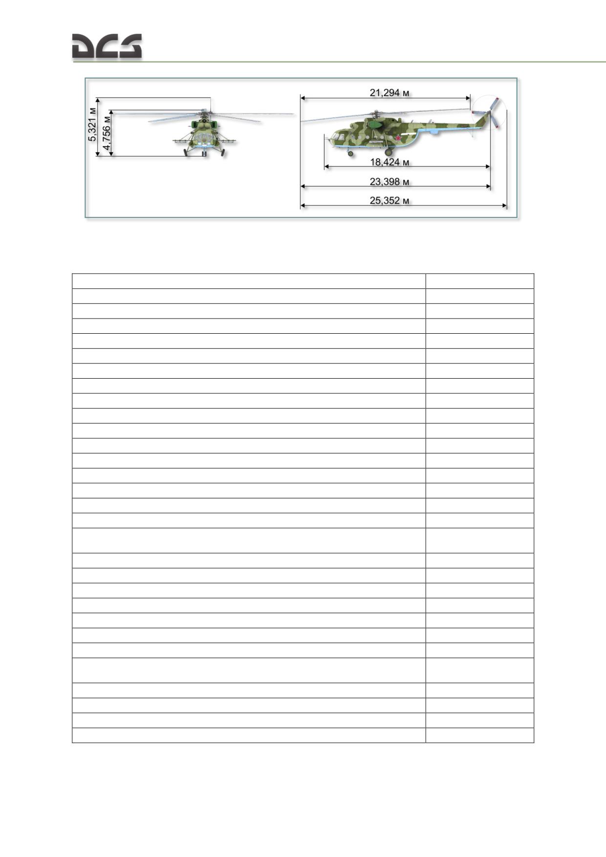
Fig. 2.1. Mi-8 dimensions
2.2. Performance specifications
Normal takeoff weight
11100 kg
Maximum takeoff weight
13000 kg
Cargo capacity:
normal
2000 kg
maximum (with full main fuel tanks)
4000 kg
troops
21-24
medical stretchers
12
Maximum level flight speed at altitudes 0 - 1000 m:
normal takeoff weight
250 km/h
maximum takeoff weight
230 km/h
Cruising speed at altitudes 0 - 1000 m:
normal takeoff weight
220-240 km/h
maximum takeoff weight
205-215 km/h
Hover ceiling with normal takeoff weight OGE (standard atmosphere)
3960 m
Service ceiling:
normal takeoff weight
5500 m
maximum takeoff weight
3900 m
Time required to reach altitude at nominal engine power and ideal climbing
speed (120 km/h), anti-icing system disabled:
normal takeoff weight
1000 m
1.8+0,5 min
3000 m
6+1 min
4000 m
9.5+2 min
maximum takeoff weight
1000 m
2.4+0,5 min
3000 m
10.9+1 min
Service range at an altitude of 500 m and cruising speed with full main
fuel tanks before 5% fuel reserve reached:
cargo load 2117 kg
495 km
cargo load 4000 kg
465 km
one full internal auxiliary fuel tank
725 km
two full internal auxiliary fuel tanks (ferry range)
950 km
20
2.3. Purpose and missions
The Mi-8MTV2 is designed to enhance mobility of ground forces and provide fire
support on the battlefield.
The primary missions performed by the helicopter include:
tactical air assault
air mobility of ground forces
transport of internal and external cargo
destruction of ground targets in the forward edge of the battle area
(FEBA) and within tactical depth, such as: infantry, lightly armored
vehicles, anti-tank positions, artillery positions, surveillance and
reconnaissance positions, air defense positions, forward command posts,
helicopters and other aircraft positioned on the ground
destruction of deployed hostile airborne (naval) assault forces
support (escort) of friendly airborne assault forces to the deployment area
and subsequent combat support
airborne reconnaissance
airborne minelaying
search and rescue operations
medical evacuation
search and destruction of air reconnaissance balloons
The Mi-8MTV2 can be configured as follows to meet mission requirements:
1. Transport:
no auxiliary fuel tanks (internal cargo capacity up to 4000 kg)
single auxiliary fuel tank (cargo cabin)
two auxiliary fuel tanks (cargo cabin)
transport of external load up to 3000 kg
2. Air assault:
transport up to 24 armed troops
3. Medevac:
up to twelve patients on stretchers plus medical assistant
mixed configuration (up to 20 men - 3 stretchers and 17 seats or 15 seats
and one auxiliary fuel tank)
4. Airborne minelaying:
equipped with VSM-1 minelaying system
5. Combat support (up to six B8-V20A rocket launchers or bombs, cannon pods,
GUV universal machine gun or automatic grenade launcher pods)
6. Ferry configuration
To facilitate transportation of special and oversize cargo (such as main rotor blades)
as well as parachute jump training, the rear cargo clamshell doors can be maintained
partially open or removed entirely.
The Mi-8MTV2 is capable of operating in day or night time conditions, visual or
instrument meteorological conditions, from prepared or unprepared airfields.
The helicopter crew consists of three crew members: pilot, copilot, and crew chief.
22
3
HELICOPTER AERODYNAMICS
DIGITAL COMBAT SIMULATOR Mi-8МТV2
3. HELICOPTER AERODYNAMICS
3.1. General principles
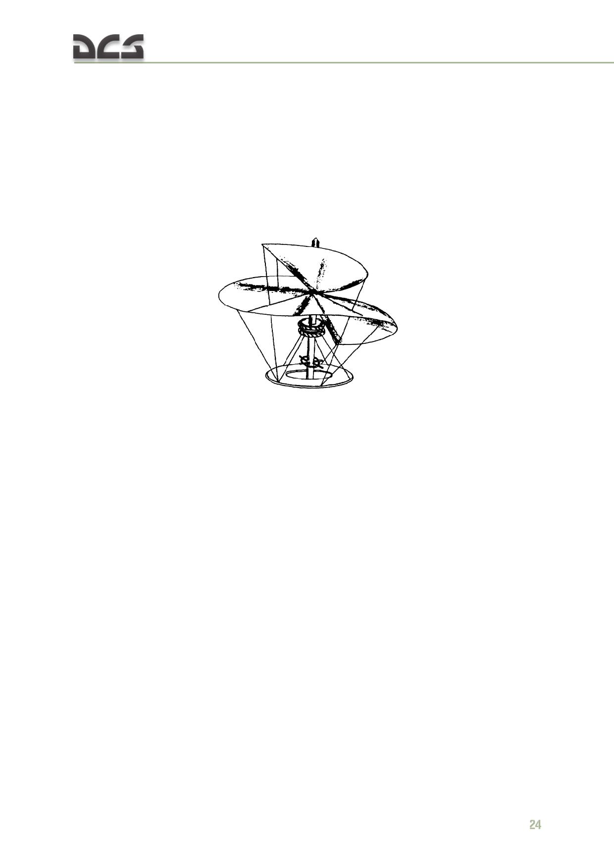
If developing vertical flight had been as simple as the idea itself, the helicopter would
have undoubtedly been the first practical aircraft. In its earliest form, the helicopter
was conceived by Leonardo da Vinci in the early 1500's. In his notes, da Vinci used
the Greek word “helix”, meaning a spiral, and combined this word with the Greek
word “pteron”, meaning wing. It is from this combination of Greek words that our
word helicopter is derived.
Fig. 3.1. Da Vinci sketch of the Helixpteron
Development proved too difficult and complicated for the early experimenters,
because they did not have an engine of sufficient power to ensure flight. When
larger, lighter, and more reliable engines were developed hundreds of years later,
the dream of a helicopter became a reality.
The same laws of force and motion that apply to fixed wing aircraft also apply to
helicopters. Helicopter controls are complex; torque, gyroscopic precession, and
dissymmetry of lift must be dealt with. Retreating blade stall also limits a helicopter's
forward airspeed.
This chapter provides a basic explanation of helicopter controls, velocity, torque,
gyroscopic precession, dissymmetry of lift, retreating blade stall, settling with power,
pendular action, hovering, ground effect, translational lift, and autorotation.
Forces acting on a helicopter
Weight (G) and drag (Q) act on a helicopter as they do on any aircraft; however, lift
(Ty) and thrust (Tx) for a helicopter are obtained from the main rotor (Trotor). In a
very basic sense, the helicopter's main rotor does what wings and a propeller do for
a fixed-wing aircraft. Moreover, by tilting the main rotor, the pilot can make the
helicopter fly to either side, forward, or backwards.
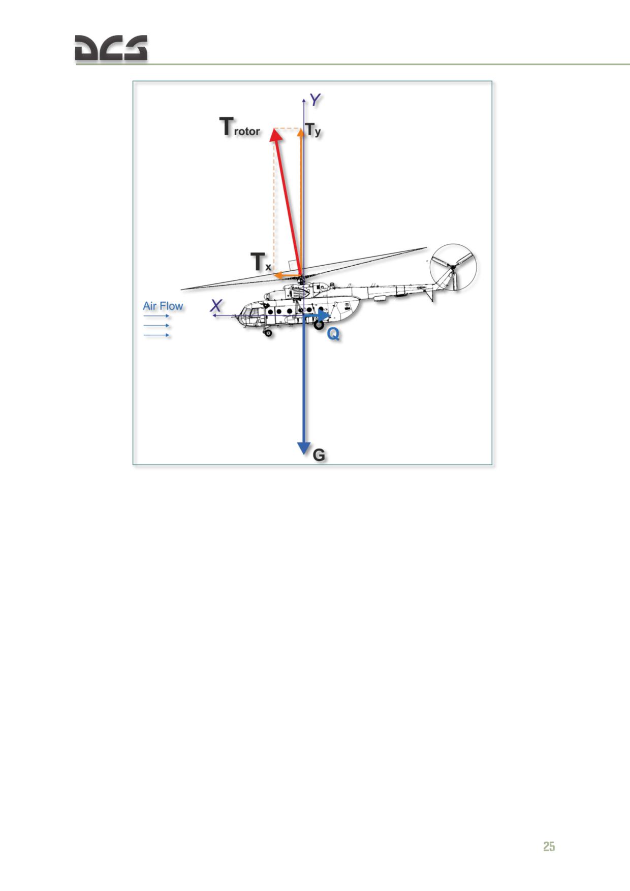
Fig. 3.2. Forces acting on a helicopter
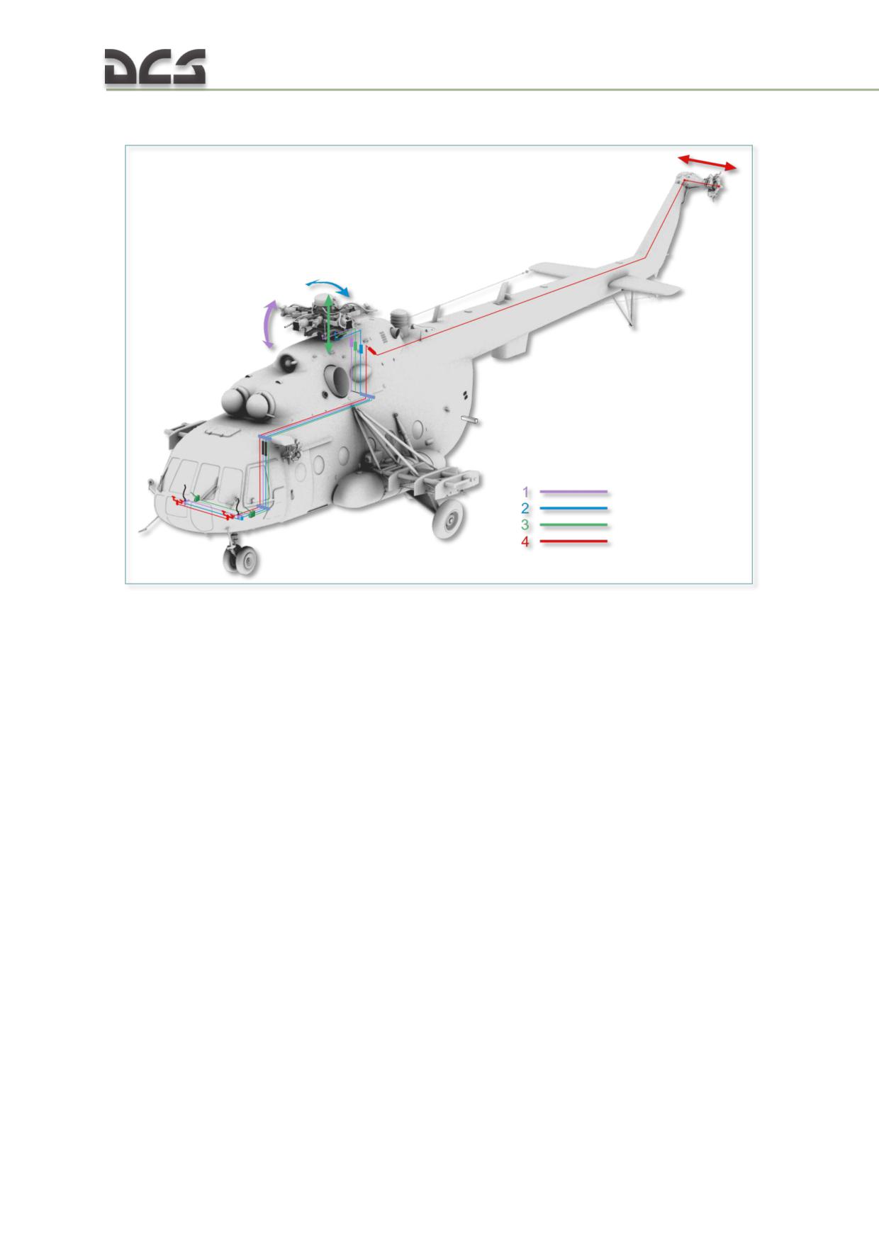
CONTROLS
Fig. 3.3. Helicopter controls
1. Longitudinal cyclic control: moving the
3. Collective pitch control: moving the
cyclic control stick forward/backward tilts the
collective lever up/down increases/decreases
main rotor disc forward/backward and causes
the pitch angle of all main rotor blades equally
the helicopter to pitch down/up
and causes an increase/decrease of main rotor
2. Lateral cyclic control: moving the cyclic
thrust (ascend/descend)
control stick left/right tilts the main rotor disc
4. Yaw control: applying the anti-torque
left/right and causes the helicopter to roll
pedals left/right makes the nose yaw in the
left/right
direction of the applied pedal and the tail yaw
right/left
The sketch in Fig. 3.3 shows the main rotor, cyclic and collective, anti-torque pedals,
and anti-torque (tail) rotor. Basically, the cyclic control is a mechanical linkage used
to change the pitch of the main rotor blades. Pitch change is accomplished at a
specific point in the plane of rotation to tilt the main rotor disc. Most current military
helicopters now have hydraulic assistance in addition to the mechanical linkages. The
collective changes the pitch of all the main rotor blades equally and simultaneously.
The anti-torque pedals are used to adjust the pitch in the anti-torque rotor blades to
compensate for main rotor torque.
Velocity
A helicopter's main rotor blades must move through the air at a relatively high speed
in order to produce enough lift to raise the helicopter and keep it in the air. When
26
the main rotor reaches required takeoff speed and generates a great deal of torque,
the anti-torque rotor can negate fuselage rotation.
The helicopter can fly forward, backward, and sideways according to pilot control
inputs. It can also remain stationary in the air (hover) with the main rotor blades
developing enough lift to hover the helicopter.
Torque
The torque problem is related to a helicopter's single-main-rotor design. The reason
for this is that the helicopter's main rotor turns in one direction while the fuselage
wants to turn in the opposite direction. This effect is based on Newton's third law
that states "To every action there is an opposite and equal reaction." The torque
problem on single-rotor helicopters is counteracted and controlled by an anti-torque
(tail) rotor.
On coaxial helicopters, the main rotors turn in opposite directions and thereby
eliminate the torque effect.
Anti-torque rotor (tail rotor)
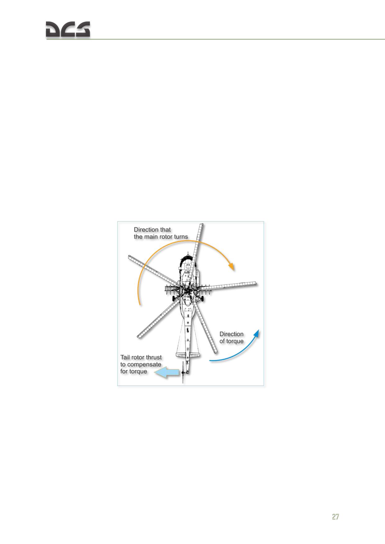
Fig. 3.4. Tail rotor and thrust
Fig. 3.4 shows the direction of travel of the main rotor, the direction of torque of the
fuselage, and the location of the anti-torque (tail) rotor.
An anti-torque rotor located on the end of a tail boom provides torque compensation
for single-main-rotor helicopters. The tail rotor, driven by the engine at a constant
speed, produces thrust in a horizontal plane opposite to the torque reaction
developed by the main rotor.
Gyroscopic precession
Controlling the rotor lift vector through gyroscopic precession is only applicable for
rotor systems utilizing a single blade hinge.
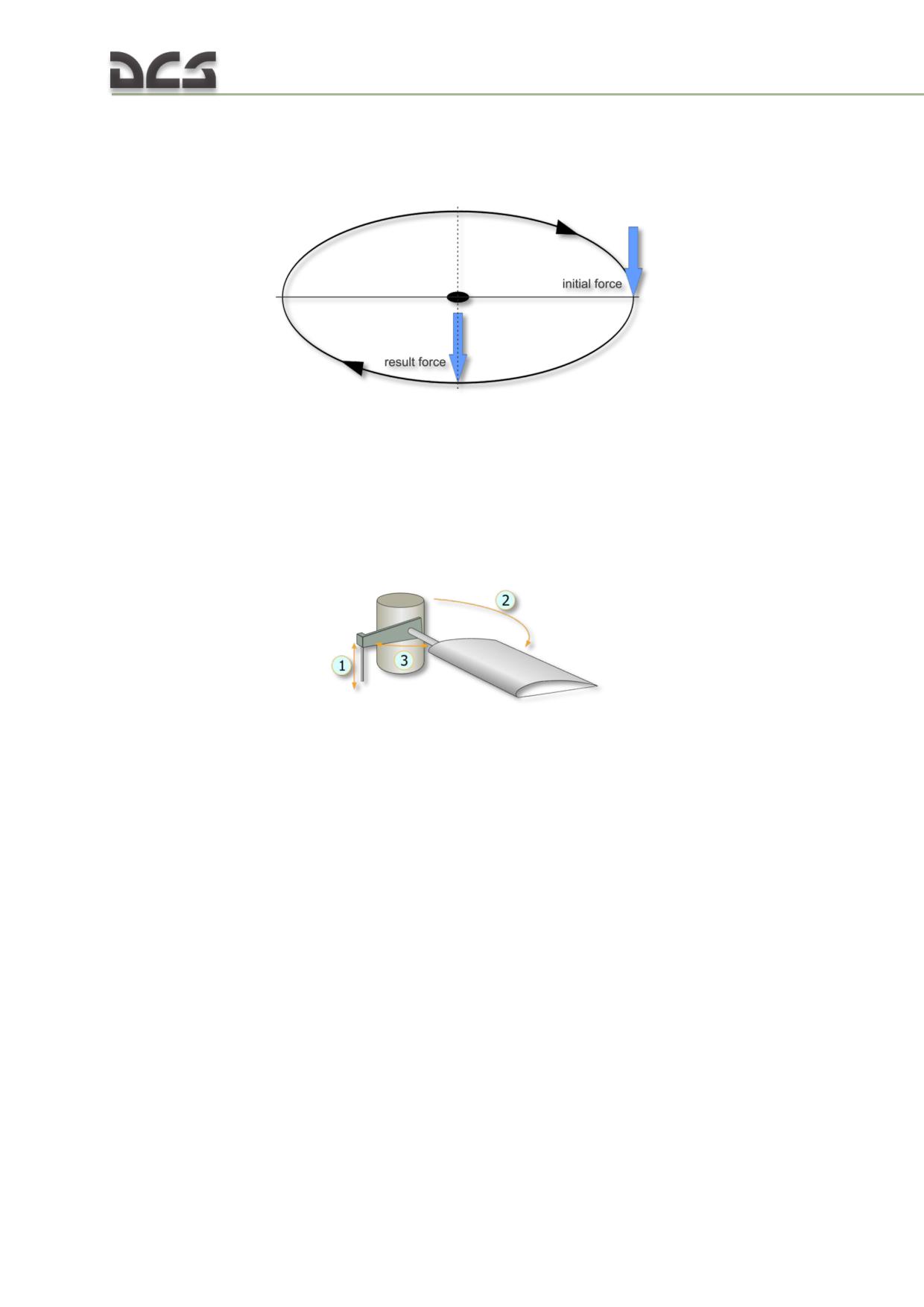
Fig. 3.5. Gyroscopic precession
The result of applying force against a rotating body occurs at 90° in the direction of
rotation from where the force is applied. This effect is called gyroscopic precession
and it is illustrated in Fig. 3.5. For example: if a downward force is applied at the 3
o'clock position in the diagram, then the result appears at the 6 o'clock position as
shown. This will result in the 12 o'clock position tilting up an equal amount in the
opposite direction.
Fig. 3.6. Offset control linkage
1. Direction of control link input and cyclic blade
3. 90 degree position ahead of the current blade
pitch adjustment
position
2. Direction of blade turn
Fig. 3.6 illustrates the offset control linkage needed to tilt the main rotor disc in the
direction the pilot inputs with the cyclic. If such a linkage were not used, the pilot
would have to move the cyclic 90° ahead of the desired direction along the direction
of turn. For example, to move the helicopter forward, he would need to move the
stick to the left. The offset control linkage is attached to a lever extending 90° in the
direction of rotation from the main rotor blade.
Dissymmetry of lift
The area within the circle made by the rotating blade tips of a helicopter is known as
the disc area or rotor disc. When hovering in still air, lift generated by the rotor
blades is equal within all parts of the disc. Dissymmetry of lift is the difference in lift
that exists between the advancing half of the disc and the retreating half; this is
created by horizontal flight and/or wind.
28
When a helicopter is hovering in still air, the tip speed of the advancing blade is
approximately 600 feet per second (~ 183 m/s) and the tip speed of the retreating
blade is the same. Dissymmetry of lift is created by the movement of the helicopter
in forward flight. The advancing blade has the combination of blade speed velocity
and that of the helicopter's forward airspeed. The retreating blade however loses
speed in proportion to the forward speed of the helicopter.
180
Airflow
230 m/sec
270°
90°
Retreating blade::
50
Advancing blade:
180-50
180+50
=130 m/sec
=230 m/sec
Helicopter forward
speed: 50 m/sec
130 m/sec
360°
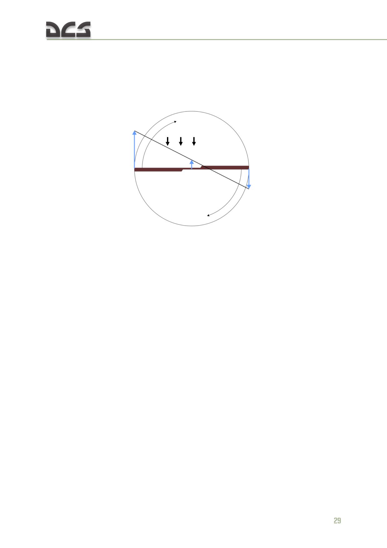
Fig. 3.7. Dissymmetry of lift: (ROTATIONAL VELOCITY) ± (HEL FORWARD SPEED) =
(AIRSPEED OF BLADE)
Fig. 3.7 illustrates dissymmetry of lift and shows the arithmetic involved in calculating
the differences between the velocities of the advancing and retreating blades. In the
figure, the helicopter is moving forward at a speed of 50 m/s, the velocity of the
rotor disc is equal to approximately 180 m/s, and the advancing blade speed is 230
m/s. The speed of the retreating blade is 130 m/s. This speed is obtained by
subtracting the speed of the helicopter (50 m/s) from the tip speed of 180 m/s. As
can be seen from the difference between the advancing and retreating blade
velocities, a large speed and lift variation exists.
Cyclic pitch control, a design feature that permits changes in the angle of attack
during each revolution of the rotor, compensates for the dissymmetry of lift. As the
forward speed of the helicopter is increased, the pilot must apply more and more
cyclic to hold a given rotor disc attitude. The mechanical addition of more pitch to
the retreating blade and less to the advancing blade is continued throughout the
helicopter's range.
Retreating blade stall
Retreating blade stall is the tendency of a helicopter's retreating blades to stall in
forward flight. This is a major factor in limiting a helicopter's maximum forward
airspeed. Just as the stall of a fixed wing aircraft wing limits the low-airspeed flight
envelope, the stall of a rotor blade limits the high-speed potential of a helicopter.
The airspeed of a retreating blade slows down as forward airspeed is increased. The
retreating blade must produce an amount of lift equal to that of the advancing blade.
As the airspeed of the retreating blade is decreased with forward airspeed, the blade
angle of attack must be increased to equalize lift throughout the rotor disc area. As
this angle of attack is increased, the blade will eventually stall at some high, forward
airspeed as shown in Fig. 3.10.
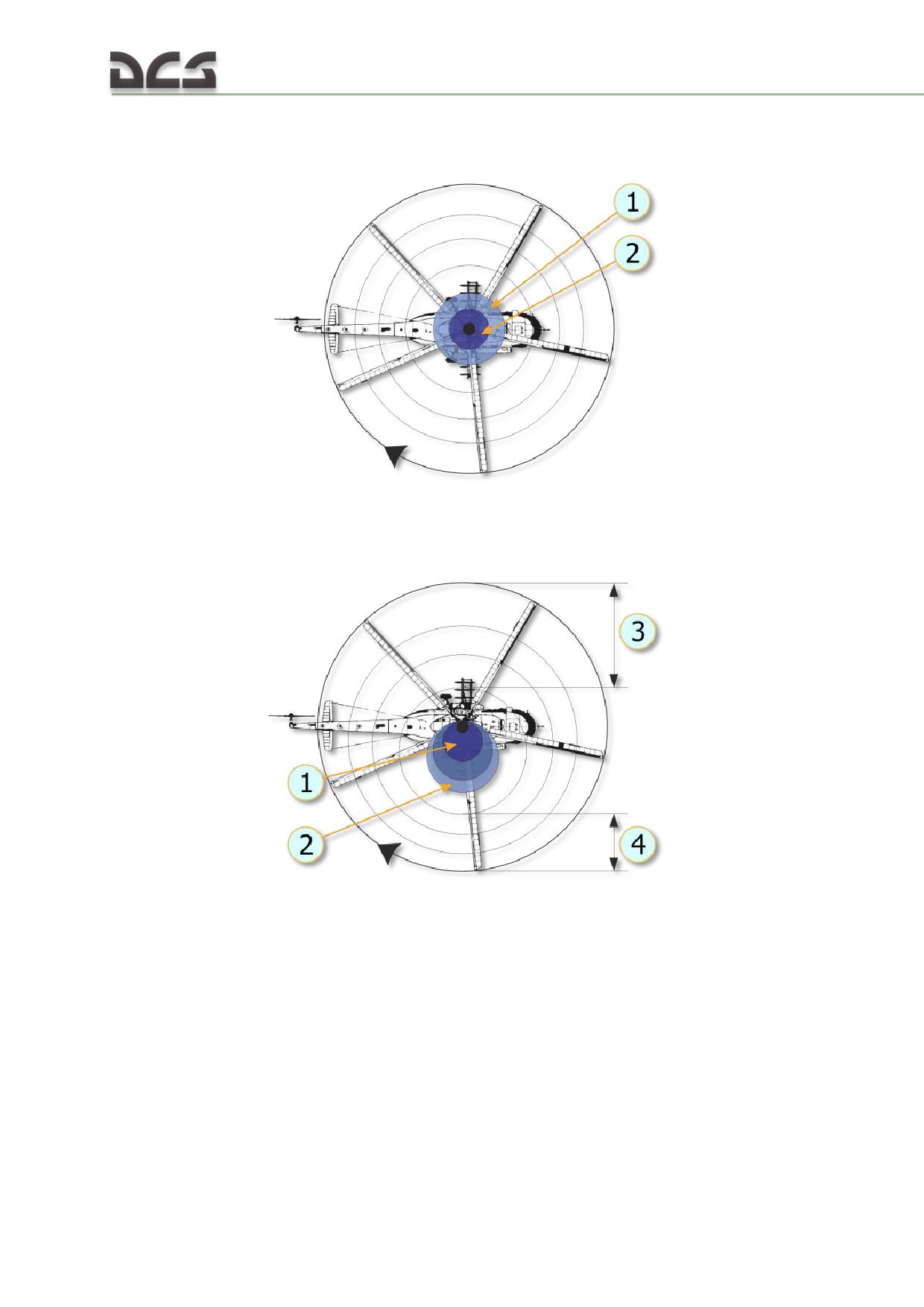
Fig. 3.8. Hovering lift pattern
1. No lift area
2. Blade root area
Fig. 3.9. Normal cruise lift pattern
1. Reverse airflow area
4. Lift produced in this area requires greater
2. No lift area
blade angle of attack (lift must equal that of zone
3. Lift produced in this area requires low blade
3)
angle of attack
30
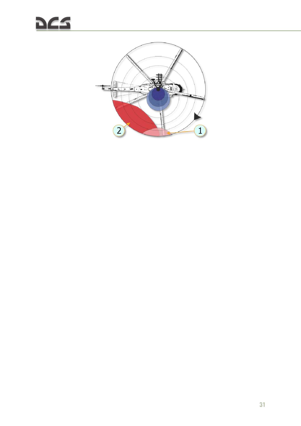
Fig. 3.10. Lift pattern at critical airspeed
1. Area of blade tip stall, causes vibration and
2. If blade angle of attack continues to remain
buffeting
high, stall area increases. The helicopter pitches
up and rolls right (stalling)
Upon entry into a retreating blade stall, the first noticeable effect is vibration of the
helicopter. This vibration is followed by the helicopter's nose lifting with a rolling
tendency. If the cyclic is held forward and the collective is not reduced, the stall will
become aggravated and the vibration will increase greatly. Soon thereafter, the
helicopter may become uncontrollable.
To recover from a stall:
reduce collective pitch
neutralize cyclic
reduce airspeed
increase rotor RPM
Settling with power (Vortex Ring State)
Settling with power is a condition of powered flight when the helicopter settles into
its own main rotor downwash; this is also known as Vortex Ring State (VRS).
Conditions conducive to settling with power include a vertical, or nearly vertical,
descent of at least 4 m/s with low forward airspeed. The rotor system must also be
using some of the available engine power (from 20 to 100%) with insufficient power
available to retard the sink rate. These conditions occur during approaches with a
tailwind or during formation approaches when some aircraft are flying in the
downwash of other aircraft.
Under the conditions described above, the helicopter may descend at a high rate that
exceeds the normal downward induced flow rate of the inner blade sections. As a
result, the airflow of the inner blade sections is upward relative to the disk. This
produces a secondary vortex ring in addition to the normal tip vortex. The secondary
vortex ring is generated at about the point on the blade where airflow changes from
up to down. The result is an unsteady turbulent flow over a large area of the disk
that causes loss of rotor efficiency, even though power is still applied.
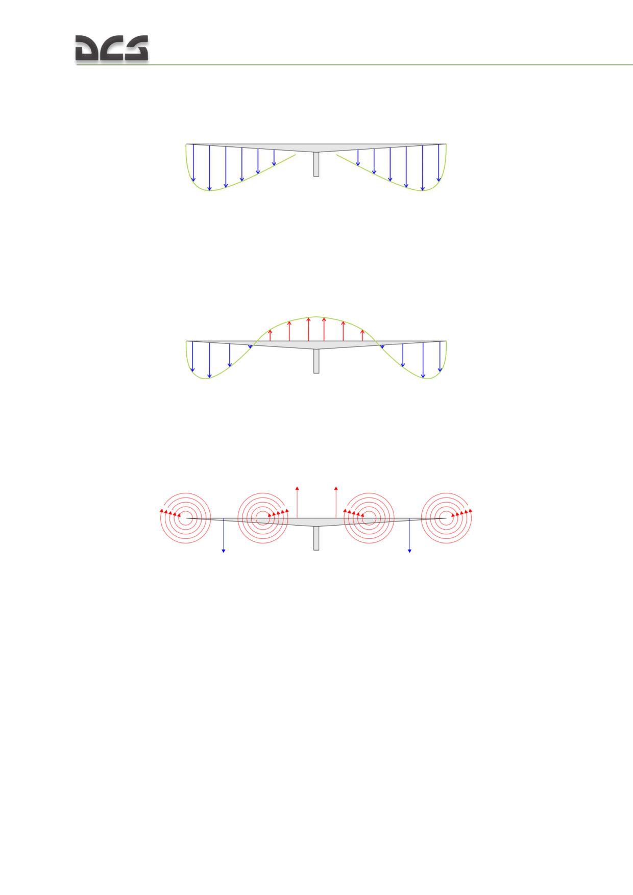
Fig. 3.11. Induced flow velocity during hovering flight
The downward velocity is highest at the blade tip where blade airspeed is highest. As
blade airspeed decreases towards the center of the disk, downward velocity is less.
Fig. 3.12 shows the induced airflow velocity pattern along the blade span during a
descent conducive to settling with power.
Fig. 3.12. Induced flow velocity during Vortex Ring State
The descent is so rapid that the induced flow at the inner portion of the blades is
upward rather than downward. The upward flow caused by the descent can
overcome the downward flow produced by blade rotation.
Fig. 3.13. Vortex rotation flows along the blades during VRS
If the helicopter descends under these conditions, with insufficient power to slow or
stop the descent, it will enter a vortex ring state.
During a vortex ring state, roughness and loss of control is experienced because of
the turbulent rotational flow on the blades and the unsteady shifting of the flow
along the blade span.
Power settling is an unstable condition, and if allowed to continue, the sink rate will
reach sufficient proportions for the flow to be entirely up through the rotors. This can
result in very high descent rates. Recovery may be initiated during the early stages
of power settling by putting on a large amount of excess power. This excess power
may be sufficient to overcome the upward flow near the center of the rotor disc. If
the sink rate reaches a higher rate, power will not be available to break this upward
flow and thus alter the vortex ring state of flow.
32
Normal tendency is for pilots to recover from a descent by application of collective
pitch and power. If insufficient power is available for recovery, this action may
aggravate power settling and result in more turbulence and a higher rate of descent.
Recovery can be accomplished by lowering collective pitch and increasing forward
speed (pushing the cyclic forward). Both of these methods of recovery require
sufficient altitude to be successful.
Hover
A helicopter hovers when it maintains a constant position over a point on the ground,
usually a few feet above the ground. To hover, a helicopter's main rotor must supply
lift equal to the total weight of the helicopter, including crew, fuel, and if applicable,
passengers, cargo, and armaments. The necessary lift is generated by rotating the
blades at high velocity and increasing the collective pitch angle of the rotor blades.
When hovering, the rotor system requires a large volume of air upon which to work.
This air must be pulled from the surrounding air mass; this is an expensive maneuver
that takes a great deal of engine horsepower. The air delivered through the rotating
blades is pulled from above at a relatively high velocity, forcing the rotor system to
work in a descending column of air.
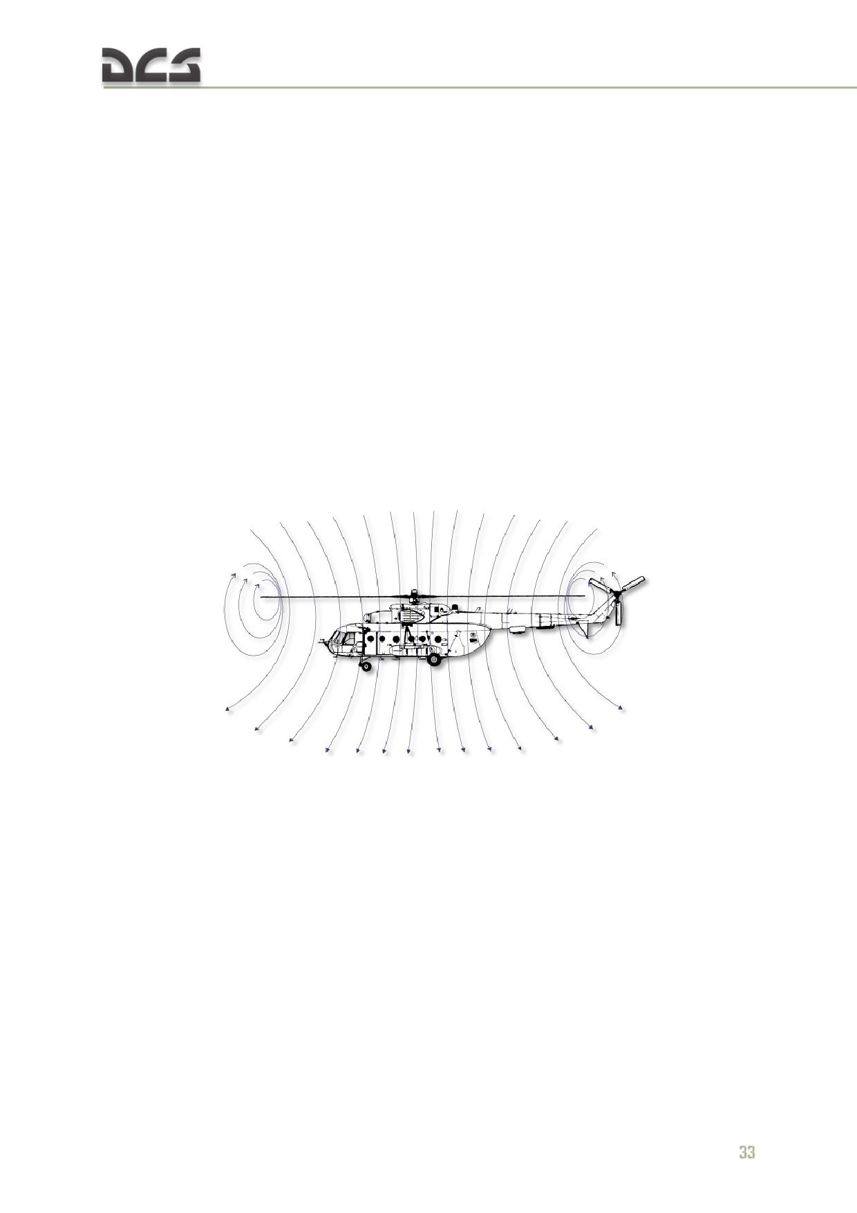
Fig. 3.14. Airflow when out of ground effect
The main rotor vortex and the recirculation of turbulent air add resistance to the
helicopter while hovering. Such an undesirable air supply requires higher blade
angles of attack and an expenditure of more engine power and fuel. Additionally, the
main rotor is often operating in air filled with abrasive materials that cause heavy
wear on helicopter parts while hovering in the ground effect.
Ground effect
Ground effect is a condition of improved performance found when hovering near the
ground. The effect begins to occur when hovering at an altitude equal to
approximately the radius of the main rotor (5-10 m for most helicopters) and
increases as altitude decreases.
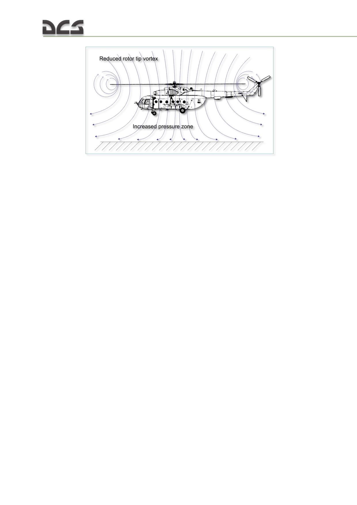
Fig. 3.15. Airflow when in ground effect
The improved lift and airfoil efficiency while operating in ground effect is due to a
number of effects. First, and most importantly, the main rotor-tip vortex is reduced.
When operating in the ground effect, the downward and outward airflow reduces the
vortex. A vortex is an airflow rotating around an axis or center. This makes the
outward portion of the main rotor blade more efficient. Reducing the vortex also
reduces the turbulence caused by recirculation of the vortex.
The second important factor is a reduction in the downwash airflow velocity by the
ground, which produces a zone of increased air pressure below the helicopter. This
affects the rotor system and increases lift. The maximum lift coefficient produced by
ground effect at zero altitude is 1.2.
Translational lift
The efficiency of the hovering rotor system is improved by each knot of incoming
wind gained by forward motion of the helicopter or by a surface headwind. As the
helicopter moves forward, fresh air enters in an amount sufficient to relieve the
hovering air-supply problem and improve performance. At approximately 40 km/h,
the rotor system receives enough free, undisturbed air to eliminate the air supply
problem. At this time, lift noticeably improves and the helicopter begins to climb.
This distinct change is referred to as translational lift. At the instant of translational
lift, and as the hovering air supply pattern is broken, dissymmetry of lift is created.
As airspeed increases, translational lift continues to improve up to the speed that is
used for best climb.
34
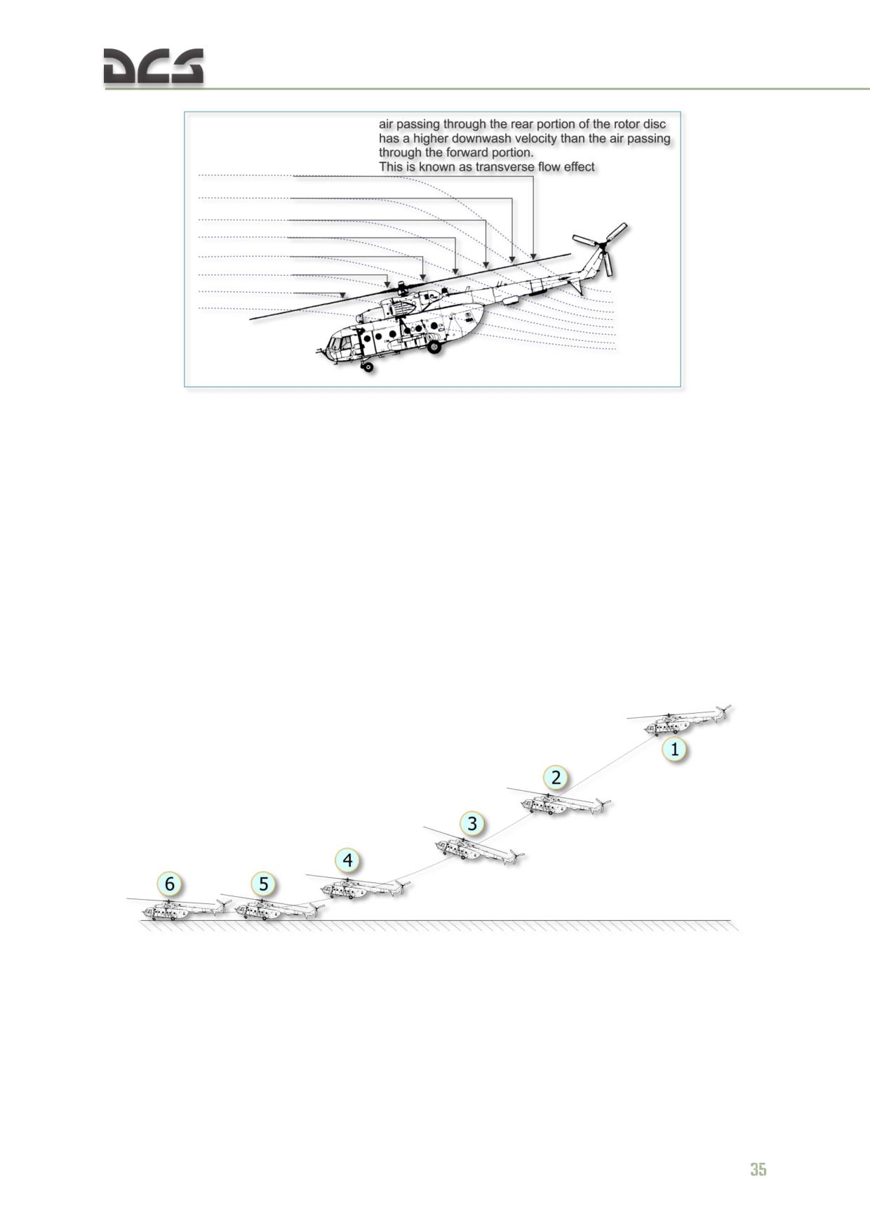
Fig. 3.16. Translational lift
In forward flight, air passing through the rear portion of the rotor disc has a higher
downwash velocity than the air passing through the forward portion. This is known
as transverse flow effect and is illustrated in Fig. 3.16. This effect, in combination
with gyroscopic precession, causes the rotor to tilt sideward and results in vibration
that is most noticeable on entry into effective translation.
Autorotation
If engine power fails, or other emergencies occur, autorotation is a means of safely
landing a helicopter. The transmission in a helicopter is designed to allow the main
rotor to turn freely in its original direction when the engine stops. Fig. 3.17 illustrates
how the helicopter is allowed to glide to earth and by using the main rotor rpm,
make a soft landing.
Fig. 3.17. Approach to landing, power off
1. While descending, establish 70-80 km/h IAS,
3. At 20-30 m altitude, raise collective to reduce
lower collective to maintain safe rotor RPM
rate of descent. This requires precise control and
(collective full down)
timing
2. At 35-50 m altitude, increase pitch to 10
4. At 4-6 m altitude, set landing pitch attitude
degrees above horizon
5. Landing
6. Short landing run to complete stop
In autorotation, the helicopter pilot exchanges potential energy (altitude) for kinetic
energy (speed) required to maintain rotor RPM. This is accomplished by establishing
a gliding descent to provide sufficient continuous airflow for the rotor system.
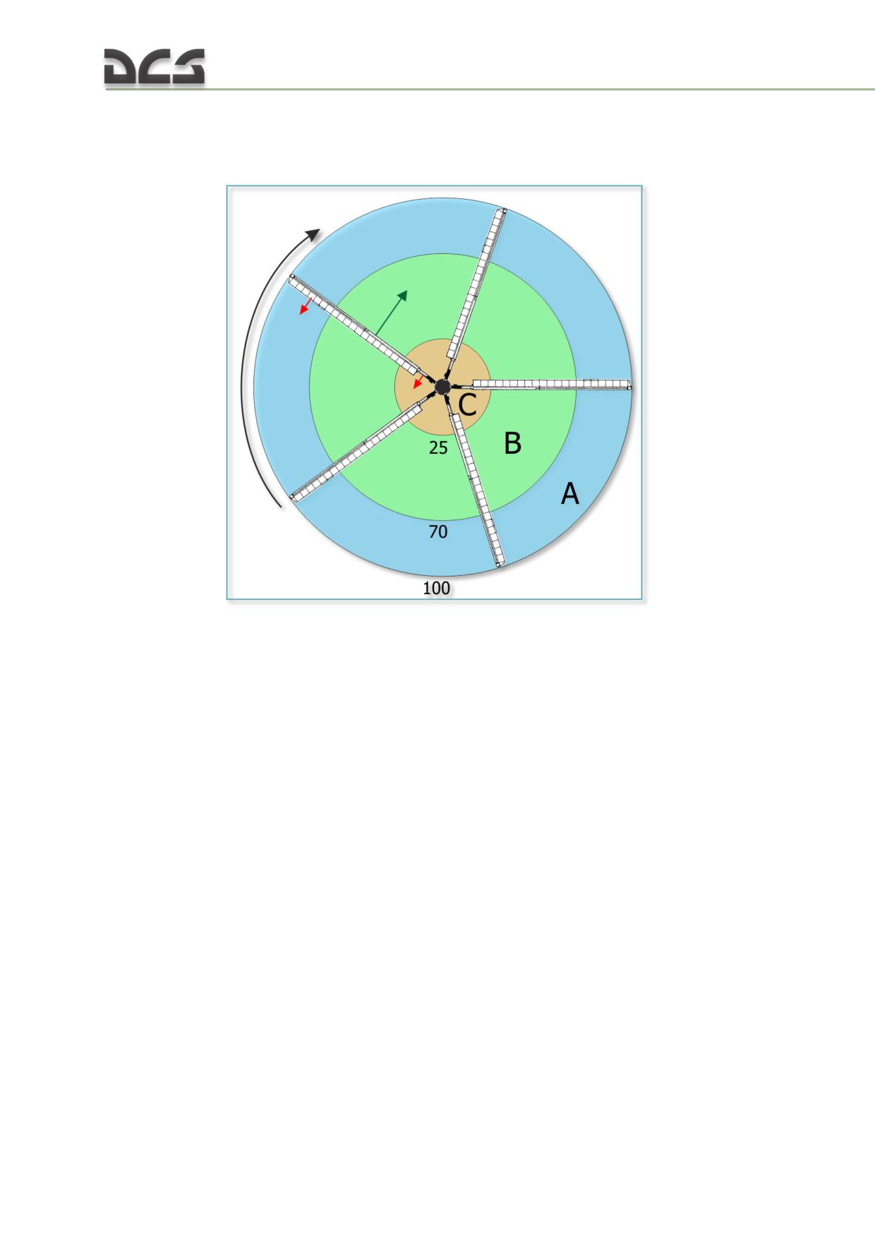
Fig. 3.18. The rotor blade autorotative regions
As shown in Fig. 3.19, the rotor disc dynamics during autorotation can be broken into
three regions: outboard, middle, and inboard.
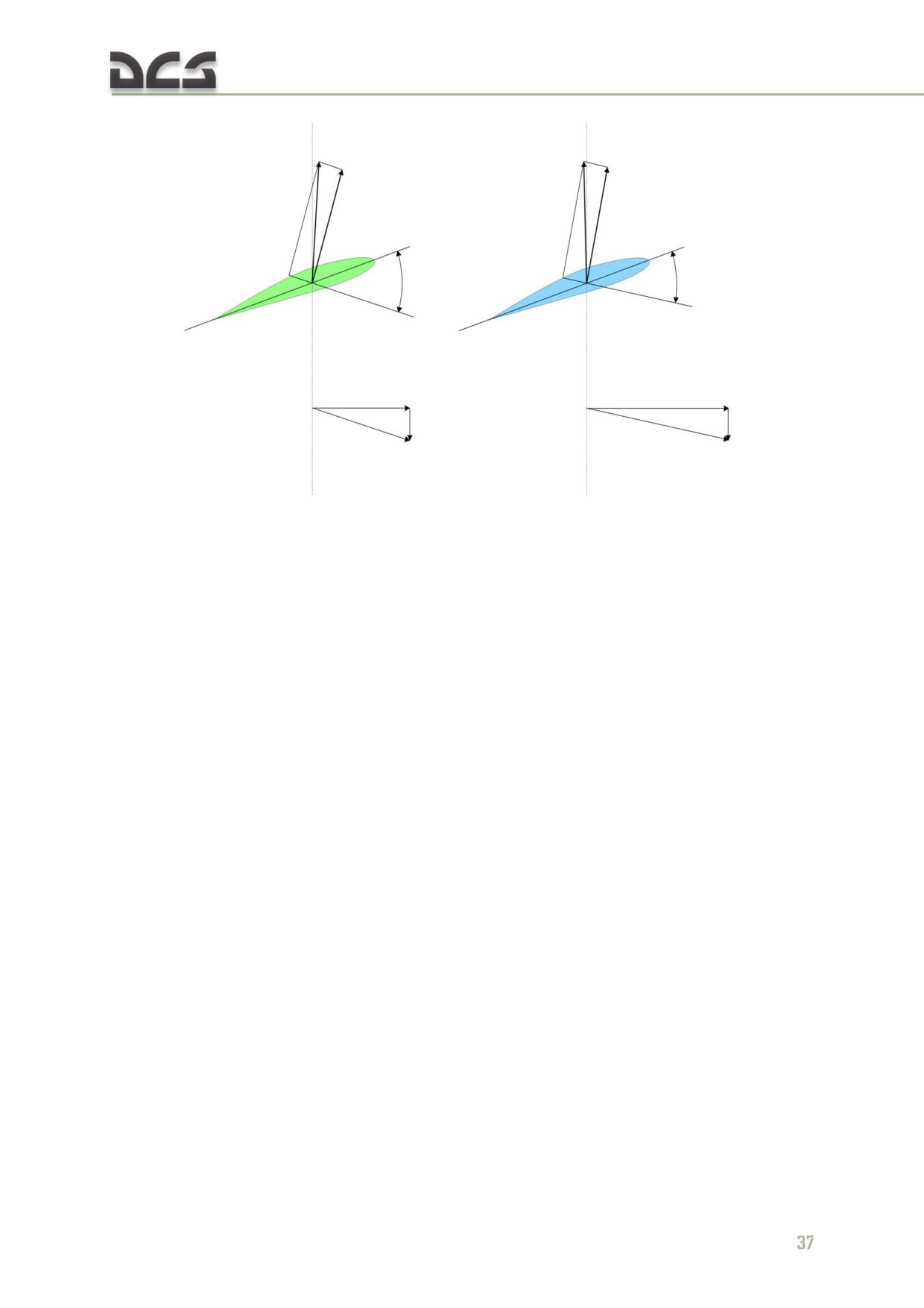
A: The outboard blade area is known as the propeller or driven region. Analysis of
blade region A indicates the aerodynamic force inclines slightly behind the rotating
axis. This inclination causes a small drag force that tends to slow the tip portion of
the blade.
B: The rotor blade autorotative driving region is the portion of the blade between 25
to 70 percent radius. Because this region operates at a comparatively high angle of
attack, the result is a slight but important forward inclination of aerodynamic forces.
This inclination supplies thrust slightly ahead of the rotating axis and tends to speed
up this portion of the blade during autorotation.
C: The blade area inboard of the 25% circle is known as the stall region, because it
operates above its maximum angle of attack. This region contributes considerable
drag that tends to slow the blade.
36
In driving or autorotative area
In driven or propeller area
Autorotative
Anti-autorotative
force
force
а
а
VT
VT
Resultant
Rate of descent
Resultant
Rate of
Axis of Rotation
descent
Axis of Rotation
Fig. 3.19. Autorotation blade forces
When performing an autorotation landing, the pilot must maintain an efficient
approach speed and glide slope of 14 - 16°. The approximate distance to the
planned landing point can be estimated by multiplying current altitude by a factor of
4. Prior to touchdown, the descent rate must be arrested by increasing collective to
ensure a safe landing. This “flare” requires precise timing. A useful rule of thumb is
that the altitude of the flare is equal to the vertical velocity multiplied by a factor of 3
- 4. For example, if the vertical velocity equals 10 m/s, the flare is performed at an
altitude of 30 - 40 meters. If the flare is particularly aggressive, the initial flare
altitude must be reduced by half.
All helicopters carry an operator's manual that has an airspeed versus altitude chart
similar to the one shown in Fig. 3.20. The shaded areas on this chart must be
avoided. This area is referred to as the "dead man's curve" and "avoid curve". The
proper maneuvers for a safe landing during engine failure cannot be accomplished in
these areas.
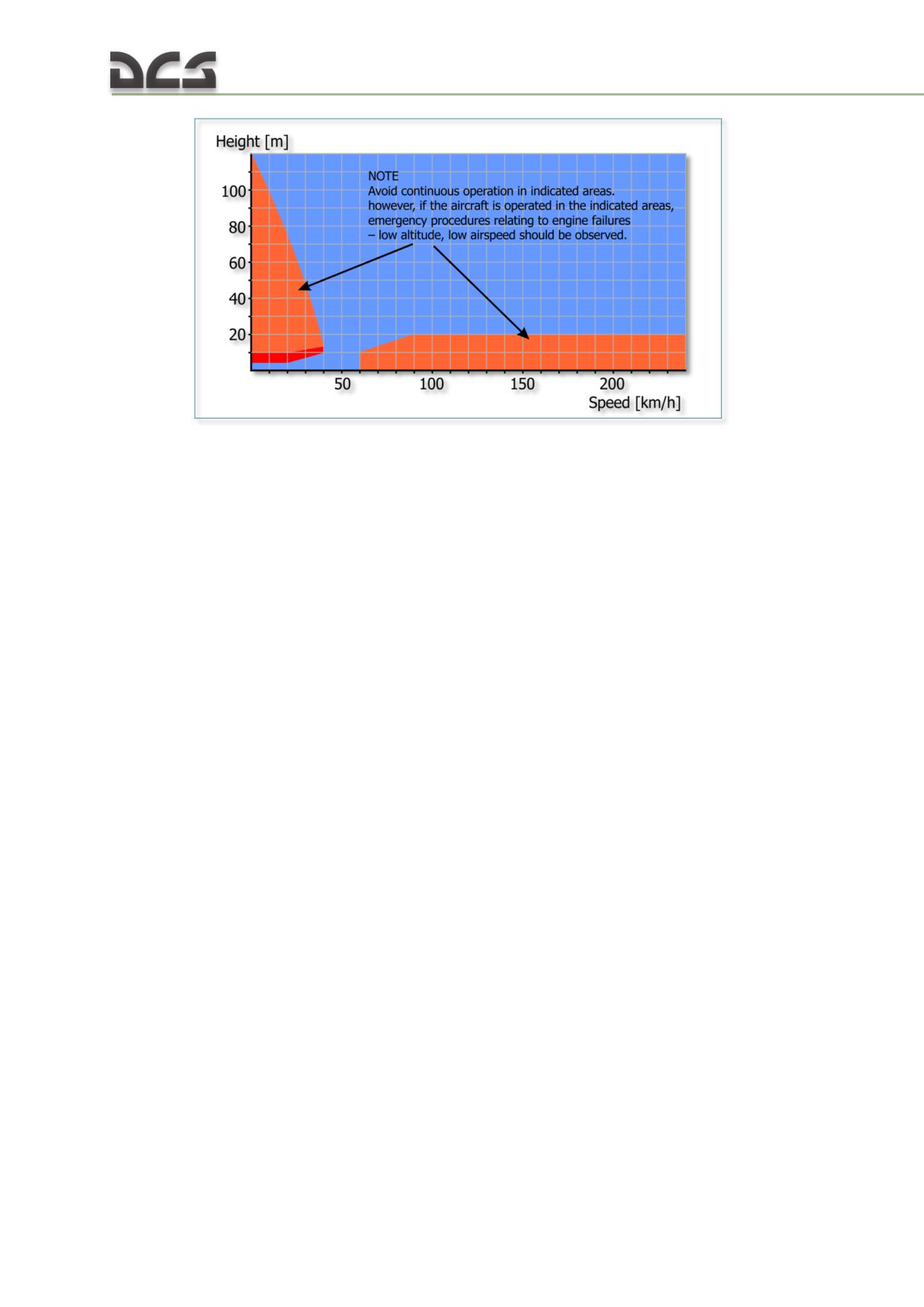
Fig. 3.20. Height-velocity diagram
Summary
Weight, lift, thrust, and drag are the four forces acting on a helicopter. The cyclic for
directional control, the collective pitch for altitude control, and the anti-torque pedals
to compensate for main rotor torque are the three main controls used in a helicopter.
Torque is an inherent problem with single-main-rotor helicopters. Gyroscopic
precession occurs at approximately 90° in the direction of rotation from the point
where the force is applied. Dissymmetry of lift is the difference in lift that exists
between the advancing and retreating halves of the rotor disc.
Settling with power can occur when the main rotor system is using from 20 to 100%
of the available engine power, and the horizontal velocity is under 20 km/h. At a
hover, the rotor system requires a great volume of air upon which to generate lift.
This air must be pulled from the surrounding air mass. This is a costly maneuver that
takes a great amount of engine power.
Ground effect provides improved performance when hovering near the ground at a
height of no more than approximately one-half the main rotor diameter. Translational
lift is achieved at approximately 20 km/h, and the rotor system receives enough free,
undisturbed air to improve performance. At the instant translational lift is in effect
and the hovering air-supply pattern is broken, dissymmetry of lift is created.
Autorotation is a means of safely landing a helicopter after engine failure or other
emergencies. A helicopter transmission is designed to allow the main rotor to turn
freely in its original direction if the engine fails.
3.2. Mi-8MTV2 aerodynamic particulars
The Mi-8MTV2 is a conventional helicopter with a single clockwise rotating main rotor
and a single anti-torque tail rotor.
The fuselage of the helicopter is a solid-metal semi-monocoque construction with a
variable cross section. It consists of the forward and central parts, tail boom and
vertical stabilizer.
38
The horizontal stabilizer installed on the tail boom is adjusted on the ground and is
non-controllable in flight. The stabilizer improves longitudinal stability and
controllability, and ensures that required pitch control authority is available
throughout the flight envelope.
For takeoff and landing, the helicopter is equipped with non-retractable landing gear
and a tail strut. These are equipped with hydro-pneumatic shock absorbers. The tail
strut prevents the tail rotor from striking the ground in case of a landing with a large
positive pitch angle.
A five-blade main rotor creates the lifting force and thrust required for the helicopter
to perform forward flight. Additionally, the main rotor is used to control the
helicopter along the pitch and roll axes. The blades have a rectangular planform.
The tail rotor creates the side force to counter the torque from the main rotor and is
used for yaw control. The three-blade tail rotor is a pulling type with variable blade
pitch for yaw control. Rotation of the tail rotor is mechanically driven by the main
rotor via the transmission system. The direction of rotation is forward - up - back.
Tail rotor pitch is controlled from the cockpit by the anti-torque pedals operated by
the pilot(s).
The helicopter is powered by two TV3-117VM turboshaft engines. From the two-
stage power turbines, engine power is transmitted via two main power shafts to the
main gearbox. The engines are positioned on top of the cabin in front of the main
gearbox.
The helicopter has an external stores support system that allows transportation of
cargo on an external sling.
These special features determine the helicopter’s aerodynamic characteristics,
stability and controllability.
Power requirement for level flight
The power requirements for level flight depend heavily on flight speed. Maximum
power demand occurs at zero forward speed (for hovering out of ground effect) and
in horizontal flight at maximum airspeed. In the speed range of 0 to 110-120 km/h,
power requirements for level flight decrease as airspeed increases, but further
increases of airspeed demand increasing power.
Main rotor thrust
With the PZU particle separator system switched off, the free thrust of the main rotor
is 13200 kg with the engines operating in takeoff power mode (3800 hp) in standard
atmosphere at sea level in calm winds. In the same conditions, in nominal engine
power mode (MAX LTD CRUISE) (3400 hp), the thrust is 12040 kg. Activation of the
PZU particle separator system reduces thrust by approximately 200 - 300 kg.
Main rotor thrust varies strongly depending on atmospheric conditions: free air
temperature (FAT), wind speed and direction, and barometric pressure at the altitude
of the airfield. This variability necessitates performing a hover safety check prior to
initiating any takeoff to ensure safe flight operations. For a takeoff In Ground Effect
(IGE), the hover check is performed at 3 m above ground at airfields located at
altitudes of up to 3000 m and at least 4 m above ground at airfields located at
altitudes higher than 3000 m. The height of the hover safety check for a takeoff Out
of Ground Effect (OGE) must be at least 10 m.
3.3. Mi-8MTV2 performance particulars
Minimum flight speed with normal takeoff weight for altitudes below 4000 m and
with maximum takeoff weight for altitudes below 3000 m is 60 km/h. Maximum flight
speed for altitudes below 1000 m is 250 km/h with normal takeoff weight and 230
km/h with maximum takeoff weight. The speed limit lowers as altitude increases up
to the operational ceiling. Optimum climbing speeds are 120 km/h for altitudes below
2000 m and 100 km/h for altitudes of 4000 m and higher. Optimum cruising speed is
10 km/h above optimum climbing speed.
The vertical rate of climb near the ground is 9 m/s with normal takeoff weight (anti-
icing system switched off) and 7 m/s with maximum takeoff weight without the
external weapons stations fitted. Activation of the anti-icing system reduces rate of
climb by 1 m/s.
The operational ceiling with normal takeoff weight without external station racks is
5000 (anti-icing system off) or 4900 (anti-icing system on) m. With maximum takeoff
weight it is 3900 m (anti-icing system off) and 3600 m (anti-icing system on).
Activation of the PZU particle separator system reduces the rate of climb by 0.6 m/s.
Fitting of exhaust gas suppression (EGS) devices reduces the operational ceiling by
150 - 200 m and the rate of climb by 0.5 - 1 m/s.
Safe altitudes and airspeeds in case of a single engine failure in
flight
In case of a single engine failure in flight, a certain time is required to detect the
failure and take corrective actions. During this time, the helicopter may lose about 10
m of altitude as the automatic control system cannot set the remaining engine into
takeoff power mode immediately. If the helicopter is at a low altitude and high speed
at the moment of failure, required crew actions are to quickly gain altitude, establish
a safe flight attitude and, if necessary, find a suitable location for an emergency
landing. Altitude is gained by a 10 - 15° pitch up maneuver and deceleration of the
helicopter. For example, initial level flight airspeed of 130 - 230 km/h may result in a
deceleration to 80 km/h and an altitude gain of 30 - 100 m.
When performing a landing or hover approach, an altitude safety margin is required
in case of an engine failure in order to provide sufficient time to perform a short
ground run landing and correct any instability as a result of sudden changes in
engine power output or landing gear ground contact.
3.4. Mi-8MTV2 control particulars
The kinematic connection of the cyclic control stick with the swashplate is rigged
such that the neutral position of the stick corresponds to a forward-left tilt of the
swashplate. This is designed to minimize cyclic stick deflection from the neutral
40
position in cruise flight. Similarly, the neutral position of the pedals corresponds to a
positive pitch of the tail rotor blades, which allows the pilot to maintain the pedals in
a position near neutral in cruise flight.
The pitch control system includes a hydraulic stop that restricts the aft deflection of
the swashplate to 2°12'. Further deflection is possible only with application of greater
aft cyclic stick force (about 15 kg). The hydraulic stop is activated by a weight-on-
wheels microswitch and is designed to protect the tail boom from being struck by
rotor blades in case of an abrupt or large pull of the cyclic control during helicopter
taxi.
The yaw control system includes the SPUU-52 tail rotor pitch limit system, which
maintains required yaw authority in hovering flight in varying weather conditions
(temperature and pressure). In a hover, the required right pedal application reduces
as ambient air pressure increases. The SPUU-52 automatically adjusts the variable
stop to restrict tail rotor pitch in order to prevent overloading of the transmission or
overstressing the tail boom.
3.5. Mi-8MTV2 trimming and balancing
Ground trim
As the helicopter is initiated into motion on the ground, during taxi, ground run, and
at the moments of takeoff and touchdown, conditions may develop in which the
helicopter will tend to roll on its side with respect to an imaginary diagonal between
the nose gear and one of the main gear wheels, a condition known as a dynamic
rollover.
When positioned on the ground, the forces acting on the helicopter with running
engines are gravity, main rotor thrust, tail rotor thrust and the ground reaction forces
acting on the wheels. The tilting forces that may result in a dynamic rollover are tail
rotor thrust, lateral components of ground reaction, lateral forces acting on the
helicopter during taxi turns and, in case of incorrect pilot actions, a component of
main rotor thrust. The corrective forces are the vertical components of ground
reaction and, in case of correct pilot actions, a component of main rotor thrust.
As main rotor thrust increases, the vertical component of ground reaction forces is
reduced and its stabilizing effect weakened. The addition of any roll angle shortens
the arm of this force and further reduces its stabilizing effect. Crosswind, low
stiffness of the landing gear, a high center of gravity (CG) position - all contribute to
a potential dynamic rollover condition.
On a slippery or inclined surface with the main rotor turning, the helicopter may skid
sideways. The likelihood of a rollover or skid increases as main rotor thrust increases.
For takeoff and landing on an incline, it is preferable to align the helicopter along the
slope (nose to tail). If doing so is not possible, then the left side of the helicopter
should be positioned facing the slope (so that the right side is below the left side),
because tail rotor thrust tends to roll the helicopter left.
When taking off from an incline, rapidly increase collective pitch in the final phase up
to the moment of takeoff; when landing, rapidly reduce collective pitch to minimize
the duration of instability on the ground. In case of a sudden roll angle increase on
the ground, i.e. at the start of a dynamic rollover, either quickly reduce collective to
settle the helicopter on the ground or quickly increase collective to lift the helicopter
off the ground.
Helicopter tendencies at liftoff
In a vertical takeoff, increased power applied to the main rotor increases torque-
induced yaw if rotor RPM is constant, resulting in a left yaw tendency.
If tail rotor thrust is not increased by right pedal application at the moment of
takeoff, the helicopter yaws to the left due to torque-induced yaw.
In addition to exhibiting left yaw, at the moment of takeoff the helicopter tends to
roll and drift to the left under the force of tail rotor thrust directed to the right. These
tendencies are corrected by adjusting cyclic position to the right to direct the
downward vector of main rotor thrust to the left to counteract tail rotor thrust.
Because the rotation axis of the tail rotor is below the plane of the main rotor hub, in
a hover the helicopter is trimmed with 2 - 2.5° of roll.
When accelerating from a hover to 30 - 35 km/h, balancing the helicopter requires
moving the cyclic control significantly forward. Maximum required deflection is
reached at 40 km/h.
When accelerating from 40 - 45 km/h to 90 - 100 km/h, balancing the helicopter
requires pulling the cyclic aft from the forward position reached during initial
acceleration from a hover.
Between 100 - 130 km/h, cyclic trim is almost unchanged. As airspeed increases
beyond 120 km/h, balancing the helicopter requires progressive forward cyclic.
Maximum required deflection is reached at maximum airspeed.
This pattern of cyclic deflection versus airspeed is a result of the variations in pitch
moments of the main rotor and the fuselage at different airspeeds.
The most significant balance shift occurs in a transition from a climb at maximum
(takeoff) engine power to an autorotation glide.
Required collective pitch is reduced as airspeed increases from 0 - 100 km/h, then
begins to progressively increase as airspeed increases.
Roll TRIM
In a hover, the helicopter is trimmed with 2 - 2.5° of roll with a slight right cyclic
position.
Transitioning from a hover to forward flight up to maximum airspeed, the cyclic is
trimmed progressively left to maintain balanced flight. Maximum left deflection is
reached in a high speed autorotation glide.
Yaw TRIM
Maximum stroke travel of the tail rotor shaft (maximum right pedal application) is
required in a hover as maximum engine power output is demanded.
42
Tail rotor efficiency increases as airspeed increases, resulting in minimum required
pedal deflection in level flight at airspeeds of 170 - 180 km/h. Right pedal application
increases as airspeed increases beyond 180 km/h.
In autorotation, the friction forces in the gearbox and transmission create a turning
moment that acts in the direction of the main rotor rotation (clockwise). In this case,
yaw trim requires left pedal application to maintain heading.
Trimming in turns, spirals, and coordinated sideslips
Increased roll angles in turns and spirals, as well as the accompanying increases in
vertical G loads, require considerable pulling of the cyclic control aft. In left turns and
spirals, the required pull is greater than in right turns and spirals. Reduced engine
power modes reduce the required cyclic pull.
In spirals, roll and yaw trim do not change significantly.
Coordinated sideslips are executed with pedal application in the corresponding
direction. Induced roll angles produced as a result of pedal application are corrected
with opposite cyclic control deflection.
The Mi-8MTV2 helicopter has good static sideslip stability throughout the range of
operating airspeeds. At large sideslip angles, the required opposite deflection of the
cyclic to either side per unit of roll is reduced. At roll angles of 9 - 14°, the helicopter
becomes statically neutral in the lateral axis.
3.6. Mi-8MTV2 stability particulars
Helicopter stability is the ability to automatically return to a steady flight attitude
after an outside disturbance is neutralized. Helicopter stability can be static and
dynamic.
Static stability is the ability of the helicopter to resist changes to current flight
conditions (airspeed, angles of attack and sideslip).
Dynamic stability characterizes the helicopter’s recovery to the reference flight
condition. Dynamic stability is determined by a combination of static stability,
damping characteristics, and relationship between longitudinal and lateral axes
oscillations for current flight conditions.
Throughout the envelope of operating airspeeds, the Mi-8MTV2 demonstrates high
static sideslip stability, but low angle of attack and airspeed static stability.
The damping characteristics of a single-rotor helicopter are much weaker than those
of a fixed-wing aircraft. Besides, a helicopter has a strong dependence between the
lateral-directional and longitudinal motion.
The helicopter’s behaviour after a disturbance in the air has an oscillating character
in terms of airspeed, bank and pitch angles. The amplitude of these parameters
varies over time. Additionally, the helicopter has a slow aperiodic tendency to drift
away from a trimmed flight condition. That is, like other helicopters, the Mi-8MTV2
demonstrates an acceptable dynamic instability throughout the range of airspeeds,
including in hover, which is demonstrated by the relatively long duration (two and
more minutes in the air with the autopilot disengaged) that it maintains a trimmed
flight condition with the flight controls released in calm atmosphere conditions before
roll angle changes reach 10°.
When the autopilot is engaged, the stability characteristics of the helicopter improve
and piloting becomes easier.
3.7. Mi-8MTV2 maneuvering particulars
The capability of the helicopter to change its attitude in space, i.e. the airspeed,
altitude and flight direction, characterizes its maneuverability. To perform maneuvers
on this helicopter, you need to be aware of some of its special characteristics.
Acceleration in level flight
To accelerate, the main rotor (propulsive) thrust component directed along the flight
path must be increased. To increase this force, pitch the helicopter nose down by
pushing the cyclic control forward.
As the result of the increase of the tilt of the main rotor thrust together with the tilt
of the helicopter, the vertical component of thrust reduces, and the helicopter tends
to descend which must be compensated by increasing the collective pitch of the
rotor.
To execute horizontal acceleration at maximum rate, engine power must be
increased within 9-10 sec to takeoff power and helicopter pitch set to -15 to -20°.
While accelerating at constant engine power, maintain level flight by simultaneously
reducing the helicopter pitch angle. The acceleration time at maximum rate from 60
to 220 km/h is 26 - 36 sec. The maximum possible acceleration per second is 6-9
km/h.
Deceleration in level flight
To decelerate in level flight, increase the pitch angle of the helicopter and reduce
collective pitch.
To execute a strong level flight deceleration from airspeeds close to maximum,
increase the pitch angle of the helicopter by
10
- 15° within 8-12 sec and
simultaneously reduce collective pitch in order to maintain altitude. Collective pitch
should be reduced by no more than 2.5 - 3° on the collective pitch indicator.
During deceleration, maintain level flight by controlling the pitch angle, and when
minimum speed is approached at the end of deceleration, increase engine power and
reduce helicopter pitch angle. The average time of horizontal deceleration from 220
to 60 km/h at maximum rate is 28 sec.
44
POWERPLANT AND
4
DRIVE SYSTEM
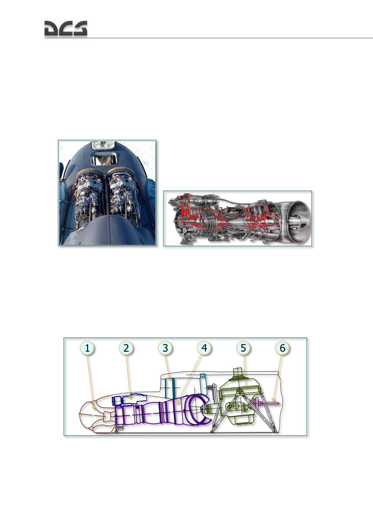
4. POWERPLANT AND DRIVE SYSTEM
This chapter contains descriptions about Engines And Related Systems, Auxiliary
Power Unit (APU), Drive System, Air Cooling System.
4.1. Engines and related systems
The Mi-8MTV2 helicopter powerplant consists of two TV3-117VM turboshaft engines.
The engines are installed on the fuselage deck in a common nacelle with the oil
cooler fan of the air cooling system.
Fig. 4.1. Engine diagram and installation on the Mi-8MTV2
The engines are situated parallel to the helicopter’s longitudinal centerline at a
distance of 600 mm from each other and are tilted downward, toward the front, at
an angle of 4°30’ relative to the fuselage horizontal reference line. The rear output
shafts of the engines are connected, via a uniball coupling, to the main transmission,
which transmits power to the main rotor, AC generators, tail rotor, and accessories.
Utilizing a twin engine system increases operational safety as one engine can provide
sufficient power for controlled flight in case of a single engine failure.
Fig. 4.2. Powertrain system diagram (side view)
1. Engine inlet and particle separator head
4. TV3-117VM engine;
("PZU");
5. VR-14 main transmission;
46
2. Air starter and accessory gearbox;
6. Tail rotor driveshaft.
3. Oil cooler fan;
TV3-117VM performance characteristics See in Table 4.1
Table 4.1
№
Performance characteristics
Value
1
direction of turbines rotation
Left
2
Engine Weight
285(+5.7) kg
3
Dimensions
length
2055 mm
width
650 mm
height
728 mm
4
Air temperature range which provide engine start
at Altitude 0 m
-60…+60°С
at Altitude 4000 m
-60…+30°С
5
Time to idle after pressing the start button (no more)
60 s
6
Fuel
T-1,TS-1 (in Russian)
7
Oil
B-3V (in Russian)
TV3-117VM general performance parameters
Engine Specifications in different Power Setting (for ISA) see Table 4.2
Table 4.2
SHAFT
RPM %
PTIT - °C
Power Setting
HORSEPOWER
N1 - All are ± 0.5%
Nr
W/O PSS
W/ PSS
W/O PSS
W/ PSS
W/O PSS
W/ PSS
MAX RATED
2200
2100
97.7
97.7
92 - 94%
920
915
TAKEOFF
2000
1900
96.6
96.6
92 - 94%
890
885
MAX LTD CRUISE
1700
1700
95.0
95.5
93 - 97%
845
855
LTD CRUISE
1500
1500
93.9
94.4
93 - 97%
815
825
CRUISE
1200
1200
92.0
92.5
93 -97%
770
780
IDLE
200
200
45 -70%
780
780
NOTE. 1. Values are shown with and without Particle Separators System (PSS) installed
2. PTIT - Power Turbine Inlet Temperature
3. N1 - Turbine RPM
4. Nr - Main Rotor RPM
5. When one engine has failed, the operating engine automatically elevates power to MAX Rated
available. MAX Rated Power operating mode can not be active for both engines simultaneously.
Other translate: MAX Rated Power operating mode one of two engine can be activated only when the
other engine failure (ie any action of the crew with (for) two simultaneously operating engines can not
be set MAX Rated Power).
TV3-117VM - Idle Speed and Maximum Starting Temperature (Fig. 4.3)
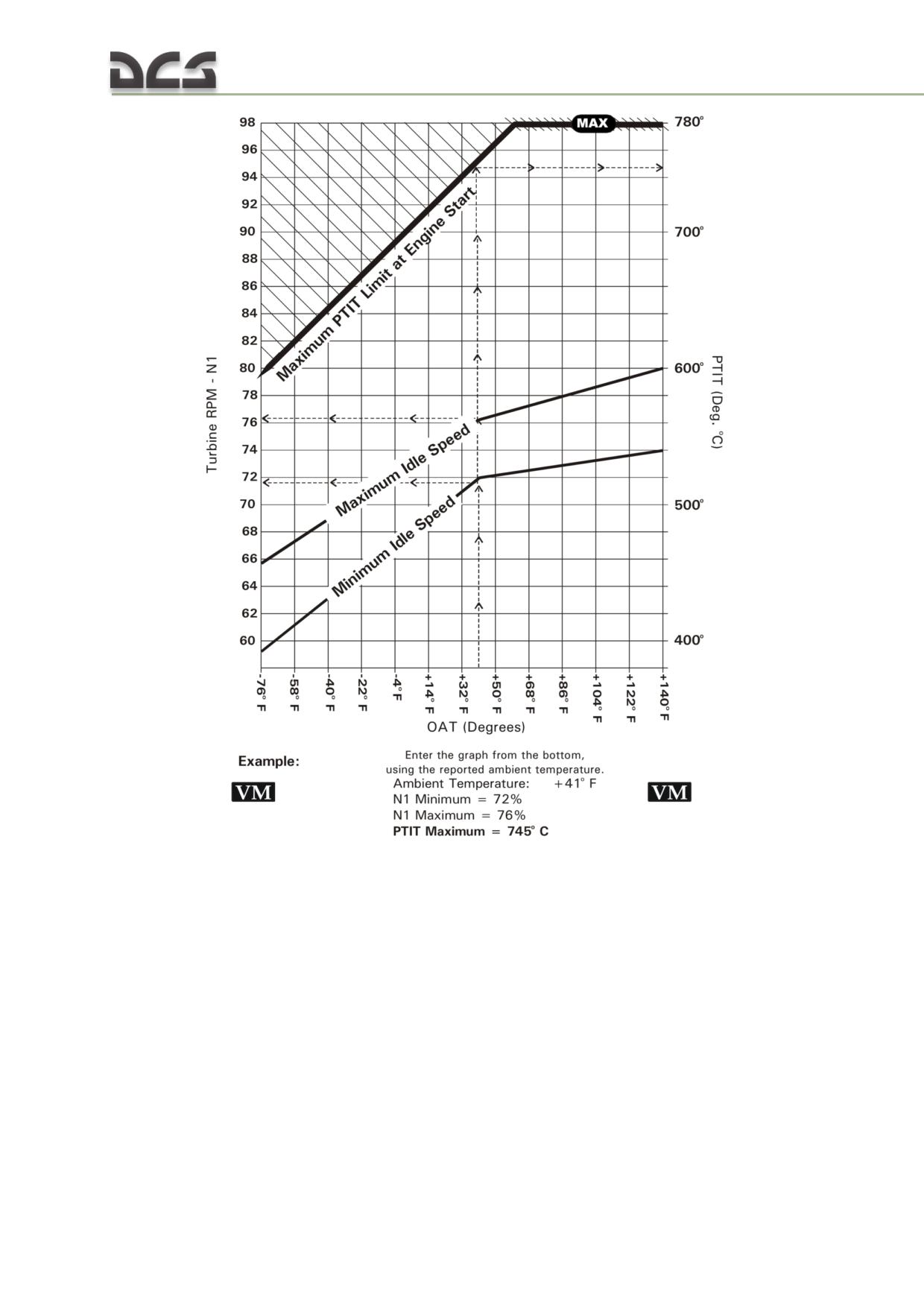
Fig. 4.3. Maximum Idle N1/Starting Temperature
The Systems of engine consists of:
Air Inlet Particle Separator
Engine Anti-Ice System
Engine Fuel System
Engine Oil System
Ignition-starting system
Engine Trim Control
The engines have an integrated regulating system which provides main rotor speed
control and synchronizes the power output of both engines. They have both
automatic and manual throttle control systems. Either engine may be operated
independently to allow for flight or emergency takeoff with one engine inoperative.
48
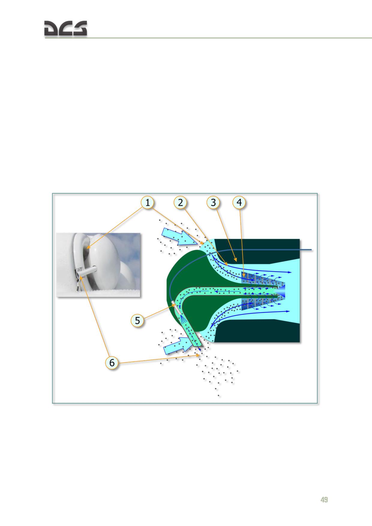
4.1.1. Air Inlet Particle Separator System ("PZU")
The "PZU" air inlet Particle Separator System (PSS), or Dust Protection Device (DPD),
protects the engine inlet during taxi, takeoff, and landing at unprepared airstrips and
in sandy/dusty environments. In addition, the system provides electrical and bleed
air anti-ice heating.
The system mounts on the front of the engine, in place of the nose cone assembly.
Each engine has an independent particle separator system. The system begins to
operate when bleed air is supplied to the ejector by opening the flow control valve.
When the system is running, suction pulls contaminated air into the inlet duct
passages (1). Centrifugal forces throw the dust particles toward the aft dome surface
(2) where they are driven by the air flow through the separator baffles (4). The main
portion of the air, with the dust removed, passes through the duct to the engine air
inlet (3). The contaminated air (dust concentrate) is pulled into the dust ejector duct
(5) and discharged overboard (6).
Fig. 4.4. Air inlet particle separator system functional diagram
The PZU anti-icing system utilizes a combination of heated air and electrical heating
to provide deicing to various helicopter components. The heated air elements of the
PZU deicing system are turned on simultaneously with the engine deicing system.
4.1.2. Engine Anti-Ice System
See 7.4.3
4.1.3. Engine Fuel System
The engine fuel system supplies and controls the fuel flow to the combustion
chamber, controls the inlet and compressor variable guide vanes and air discharge
valves, and shuts down the engine in the event of power turbine overspeed. The fuel
components mounted on the engine include the fuel control, fuel nozzle/manifold
assembly, fuel boost pump, fuel/drain valve, filters, and an emergency fuel shutoff
valve. The aircraft fuel system supplies fuel to the input of the fuel boost pump. The
fuel boost pump increases the fuel pressure to the required level and feeds it to the
main fuel filter. The main fuel filter supplies filtered fuel to the inlet of the fuel
control. The fuel control’s high pressure pump increases the pressure of the fuel. The
fuel control meters the fuel and sends the fuel in two flows through the fuel/drain
valve unit into the start and main fuel rings of the fuel nozzle/manifold assembly.
Fuel seepage from the accessory seals passes through the drainage system lines to
the ejector which discharges it into the exhaust pipe. Fuel drainage from the
combustion chamber and the air intake valve reaches the fuel/drain valve unit which
sends it to the drainage tank on the left side of the fuselage.
Starting Fuel Flow
To start the engine fuel supply, the fuel boost pumps must be operating, the engine
fire valves and service cell shutoff valve open, the twist grip throttle control rotated
full left, and the engine fuel shutoff lever (FSL) set to the OPEN (full forward)
position. During engine start, fuel is supplied to the start fuel nozzles. Air is supplied
to the main fuel nozzles during engine start to improve atomization of the start fuel.
When N1 reaches sufficient speed, fuel begins to flow through the main fuel nozzles.
Steady State Operation
The N1 regulator, droop compensator, engine governor, and temperature limiter
automatically control the fuel flow into the combustion chamber during steady state
operations. Each element affects the fuel flow only during specific conditions. The N1
RPM regulator controls the fuel flow at idle power. The droop compensator adjusts
the fuel flow at operational power conditions from flight idle up to limited takeoff.
This includes flat pitch descents. The engine governor system and the gas
temperature limiter control maximum fuel flow at limited takeoff and takeoff power.
Temperature Limiter System Operation
When power turbine inlet gas temperatures reach 985±5°C (1796-1814°F), the
temperature limiter begins to send signals to the temp limiter actuator (IM-47). The
RT LEFT (or RIGHT) ON caution light on the pilot’s left side console begins to flash.
As the PTIT continues to increase, the signal pulse duration and the flashing speed
of the caution light also increases. This results in increased fuel spillage from the
throttle control chamber through the temp limiter actuator, decreasing the amount of
fuel fed to the combustion chamber. The gas temperature limits at all power settings
50
are between 980 and 990°C (1796 and 1814°F). The fuel control includes a slide
valve that blocks the actuator if the temperature limiter fails. If the temperature
limiter sends a constant false signal or a very high temperature signal to the
actuator, the slide valve disengages the actuator when the N1 RPM decreases to
85±1%.
Compressor Control System Operation
The variable inlet guide vanes (VIGV), variable guide vanes (VGV), and two air discharge valves
maintain the basic engine performance parameters and stability margin. The guide vane controller in
the fuel control operates the compressor control system as a function of derived (corrected) N1 RPM.
During engine start, when the N1 RPM is below 81%, the VGIV and VGV are set against the upper
stop (closed) at an angle of 27 to 28.5°. When the N1 RPM reaches 81%, the guide vanes start to
open at a linear rate. When the N1 RPM reaches 100%, the guide vanes are set to an angle of 0o.
When N1 exceeds 102%, the guide vanes are fully open against the lower stop at an angle of -
3±0.5°. Reversal of the guide vane setting occurs in a similar manner as the N1 RPM decreases until
the vanes close at an N1 RPM of 81%. The air discharge controller operates the air discharge valves
at the seventh compressor stage. During engine start and low RPM operation, fuel pressure holds the
valves open. When the N1 RPM is between 84 to 87%, (VGV setting of 22°), the air discharge
controller diverts fuel to the drain line and the valves close. The valves open during engine
deceleration in the same manner.
NOTE. On TV3-117VM engines, the variable guide vanes are set to an angle of -6.5° when fully open.
Engine Governor Operation
A. N1 LOOP. The engine governor N1 loop prevents compressor overspeed by
reducing the fuel flow to the combustion chamber when the preset maximum RPM is
reached. The system uses inputs from the N1 RPM transducer mounted on the
engine accessory drive, pressure readings from a pressure transducer mounted in
the cargo cabin, and temperature readings from the engine inlet temperature probe
to monitor and correct the maximum N1 limit. The temperature limiter actuator (IM-
3A) controls the amount of fuel reduction.
B. N2 LOOP. The N2 loop activates and automatically shuts down the engine in the
event of power turbine overspeed (118±2%). The N2 loop uses the input from a pair
of N2 transducers mounted in the aft support housing to determine actual N2 speed.
The emergency fuel shutoff valve cuts off the fuel flow into the combustion chamber
and the engine shuts down if the maximum N2 speed is reached.
NOTE. TV3-117VM engines use an ERD-3VM engine governor system. On Mi-8MTV2 helicopters with
TV3-117VM engines, a power boost circuit is included in the governor system to allow maximum
power for emergency takeoff with one engine.
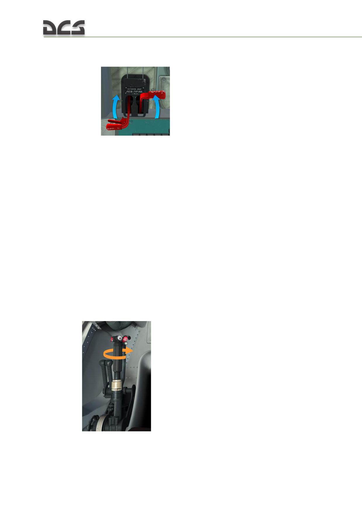
Engine Shutdown
Moving the fuel shutoff lever in the cockpit to the STOP (full aft) position controls
engine shutdown
. When this occurs, the stop valve in the fuel
control closes, diverting the fuel to the drain line. Fuel flow into the combustion
chamber terminates
Fuel Supply Switches
Fuel supply system switches and indicators are located on the center overhead
console (see Fig. 7.7). The panel includes switches for the fuel valves and transfer
pumps. Fuel supply system operation is described in Fuel System.
Power Controls
Joint engine operation is controlled using the twist grip throttle control on the pilot or
copilot collective sticks. The engines are controlled individually by the pilot’s engine
condition levers (ECLs). If one engine fails when the engines are operating at power
settings above flight idle, as long as the collective pitch remains unchanged, the
droop compensator will engage and automatically bring the operating engine to MAX
RATED (or Emergency) Power Setting to maintain the main rotor RPM. If the
automatic control systems fail, the engine power setting can be controlled by manual
adjustment of the twist grip throttle, the collective pitch, and the engine condition
levers to maintain the main rotor RPM.
A. TWIST GRIP THROTTLE/COLLECTIVE CONTROL. With the throttle turned to the full left
position and the collective stick in the full down position, the engines operate at
ground idle
. An idle stop is incorporated in the throttle linkage
to prevent inadvertent throttle closure. Rotating the throttle control to the full open
(clockwise) position allows the engine fuel control systems to maintain constant main
52
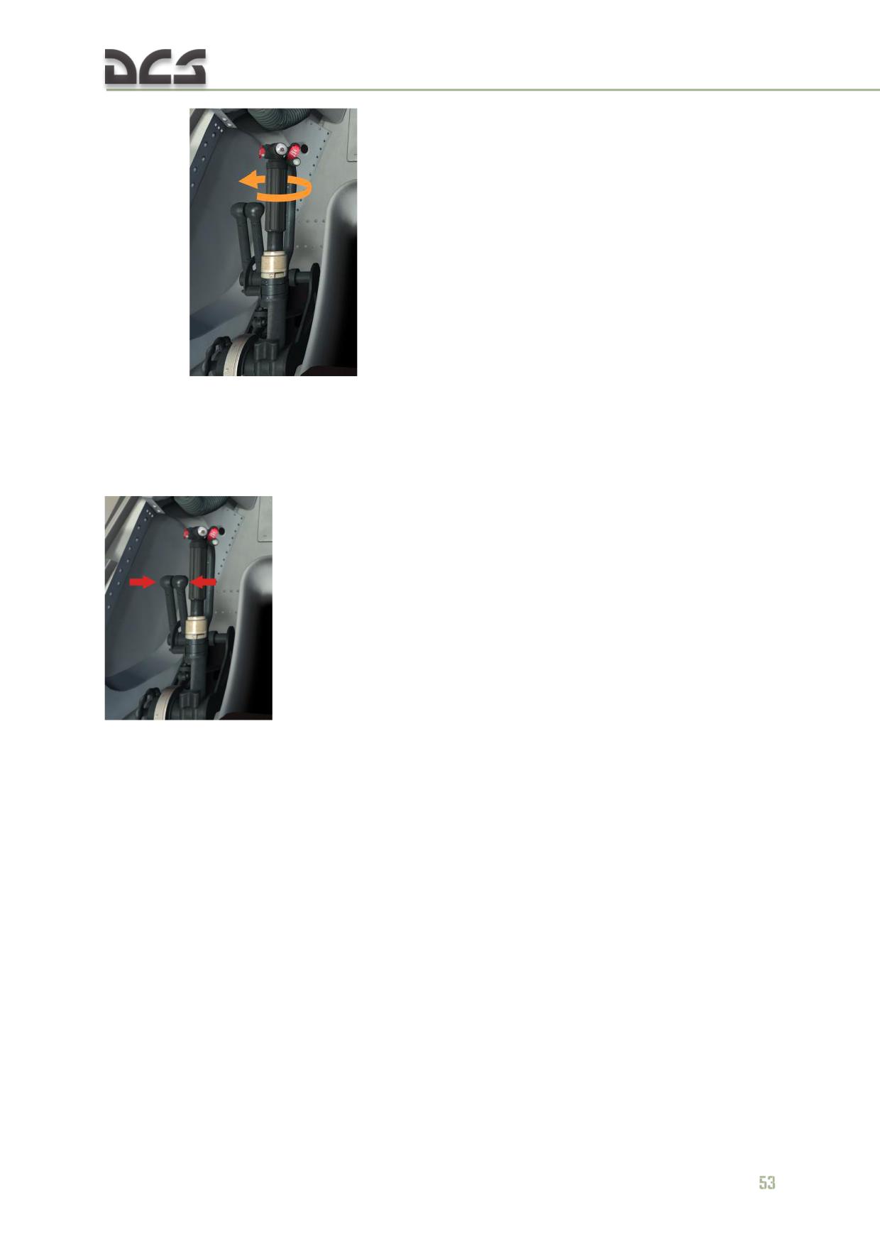
rotor RPM
. With full right throttle and the collective full down,
the engines operate at flight idle. Higher power settings are controlled by increasing
the collective pitch. At main rotor pitch of 12o and higher, the engines operate at
limited takeoff power, with maximum fuel flow controlled by the engine governor and
gas temperature limiter.
B. ENGINE CONDITION LEVERS (ECL). The ECLs
("РРУД" (RRUD) in RU)
vary the N1 control lever (throttle) settings from minimum to
maximum power separately for each engine. They are used to control the engine
power setting during ground testing and in special flight conditions such as failure
ERD-3VM engine governor system, training purposes to practice landing with one
engine shut off (for cool the engine, which will be shut down, not necessary in
game). The normal position of the ECLs is in the center detents. The engines can be
brought to takeoff power by moving the engine condition levers to the maximum
settings
C. EMERGENCY POWER OVERRIDE. In helicopters equipped with TV3-117VM engines, a
power limiter override circuit is included in the engine governor system. The circuit
resets the maximum N1 setting of the governor system to allow the engine to gain
maximum power (+0.8-1% N1: limiter increases the upper bound limit by 0.8-1%),
the resulting maximum power of operation engine will be increased by 200 hp
(+200 hp to TAKE OFF Power Setting). The pilot can activate the emergency power
circuit by setting the EMERG POWER LH (RH) switches on the engine governor
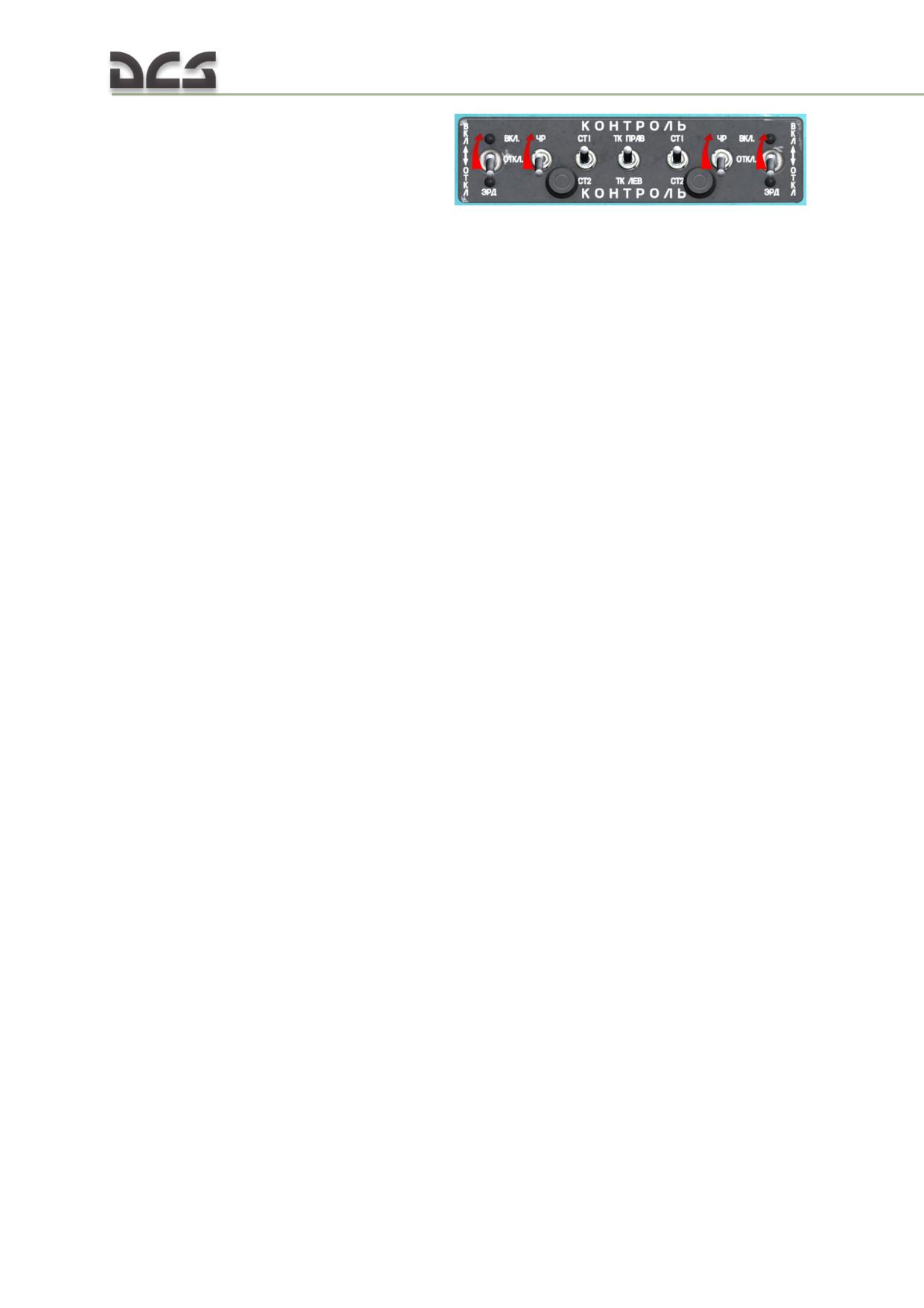
control panel to the ON (up) positions
When activated and one of two engine is failure, the EMERG PWR LH (or RH) ENG
caution light on the pilot’s master caution panel illuminates.
Engine Power Synchronizers
The engine fuel controls are linked by power synchronizers to balance joint engine
operation. The power synchronizers measure and compare the compressor delivery
pressure of both engines. The engine with the lower delivery pressure (the driven
engine) receives an increase in fuel flow which increases the N1 RPM. This action
also causes an increase in the N1 RPM of the engine with the higher compressor
delivery pressure (the driving engine). The droop compensator of the driving engine
then reduces the fuel flow and thus, the RPM of the driving engine. The power
synchronizers and droop compensators of both engines counterbalance each other
until the compressor delivery pressure of both engines is equal. The power
synchronizer only affects the fuel flow of the driven engine, while the droop
compensator affects the driving engine. If the main rotor RPM surges above 107%,
the synchronizer cutoff valve in the engine fuel control disconnects the power
synchronizer of the driven engine. The driven engine drops to flight idle, while the
driving engine continues to operate at maximum power. To adjust and maintain the
correct M/R RPM if the power synchronizer disengages, the pilot must manually
adjust the collective pitch, twist grip throttle control, or ECL.
4.1.4. Engine Oil System
The engine oil system provides lubrication, cooling, and ventilation of the engine
support bearings, drives, gears, and other moving parts of the engine. Each engine
has an independent, self-contained oil system.
Description
The engine oil system is entirely automatic in its operation. The system includes an
oil tank with deaeration provisions and sight gage, breather and vent lines, oil cooler
with an inlet chip detector, pressure sensor, pressure-activated relief and cutoff
valves, filters, and lines. Drain valves are provided for draining the oil tank and
cooler. Pressure for engine lubrication and scavenging of return oil is provided by an
integrated oil delivery and scavenge pump unit with pressure regulating and shutoff
valves, and by a separate pump which scavenges oil from the engine accessory
drive. Engine oil cooling is accomplished by an oil cooler with a thermally-activated
bypass valve. Hot oil is supplied to the oil cooler from the scavenge section of the oil
pump unit. Cooled oil is returned to the oil tank. If the temperature of the oil
scavenged from the engine is below 50°C (122°F), the thermal bypass valve opens
and the oil is diverted directly to the return line. Air circulation for oil cooling is
supplied by a turbine fan that is driven by the main transmission. The fan is powered
at all times when the engine is operating; no additional control is required.
54
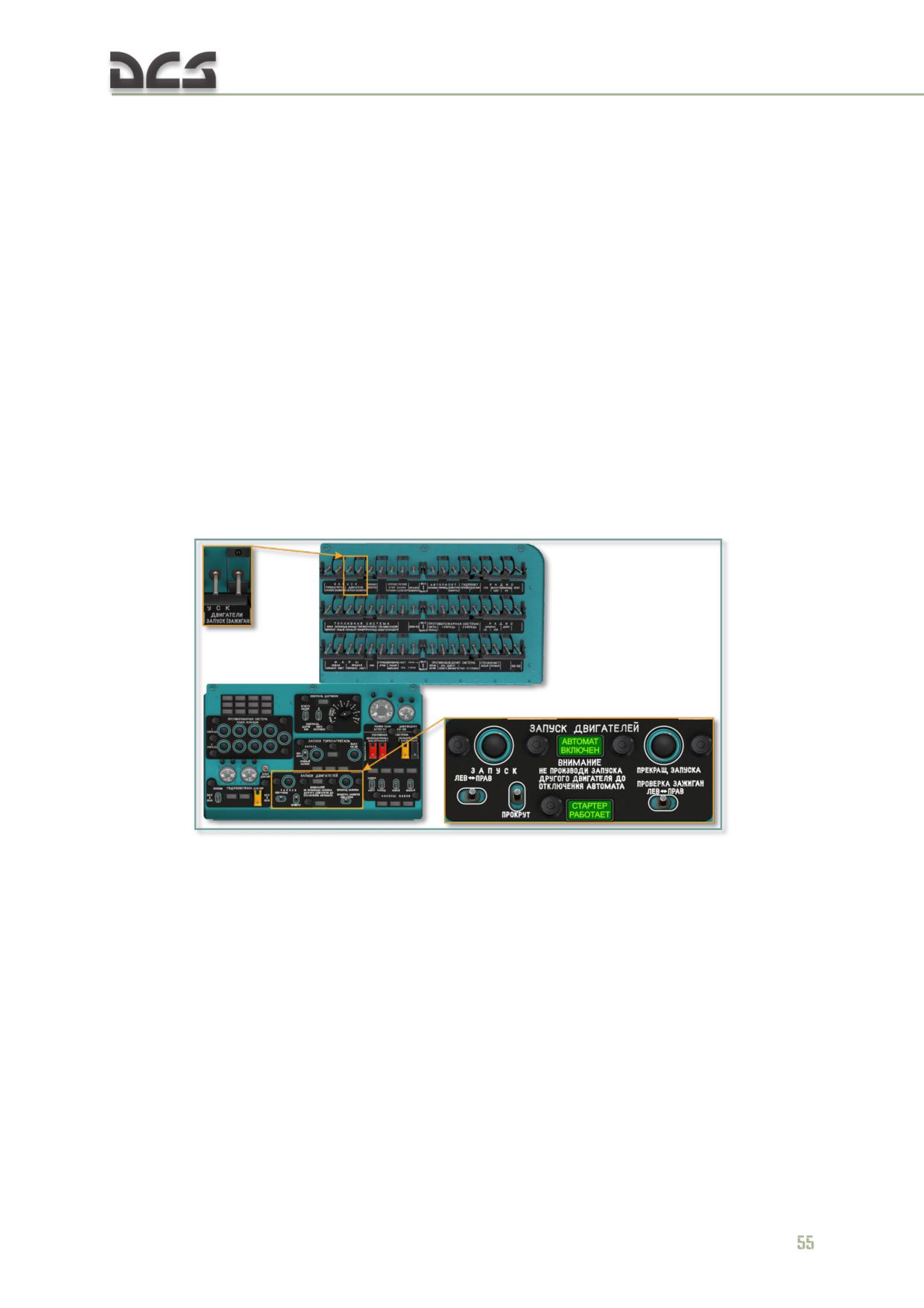
Engine Oil System оperating range see in Table 8.8
4.1.5. Ignition-starting system
Starting the APU and main engines procedure see 9.3.
The TV3-117VM engines are started by the SV-78B starter turbine, supplied with
compressed air by the APU, which begins to turn the engine compressor rotor. The
starter turbine also provides for engine cranking and false start.
The ignition-starting system includes the following components:
SV-78B starter turbine;
SK-22-2 ignition exciter;
SP-26P3 igniters (two);
APD-78A start control box (one for both engines);
protection, multiplexing, control, and signal generating equipment.
The starter turbine, ignition exciter, and igniters are installed on the engines. The
start control box, protection, multiplexing, control and signal generating equipment
are installed separately in the helicopter.
Fig. 4.5. Engine start control panel
When starting the TV3-117VM engines, turn on the START ENGINES - “START” and
“IGNIT” (ЗАПУСК - ДВИГАТЕЛИ - "ЗАЖИГАН." and "ЗАПУСК") circuit breakers. Set
the MODE ("ЗАПУСК -ПРОКРУТ.") selector on the engine start control panel to the
START (up) position and set the ENGINE (ЗАПУСК - "ЛЕВ. - ПРАВ.") selector to
correspond to the engine being started (LH or RH).
To perform an engine crank or false start, set the MODE ("ЗАПУСК -ПРОКРУТ.")
selector to the CRANK (down) position. A false start is performed with the fuel fire
(shutoff) valve open, fuel shutoff lever full forward (open), and fuel service cell boost
pump engaged. A crank is performed as a false start, except the fuel shutoff lever is
held in the aft position (closed).
The start control program is engaged by pressing the START ("ЗАПУСК") pushbutton
and can be aborted manually at any time by pressing the ABORT START
("ПРЕКРАЩ. ЗАПУСКА") pushbutton on the engine start control panel.
The AUTO IGNITION ON ("АВТОМАТ ВКЛЮЧЕН") light illuminates to advise that the
start cycle is in progress. It is controlled by the engine start control box. The
STARTER ON ("СТАРТЕР РАБОТАЕТ") light illuminates when sufficient air pressure is
delivered to the engine starter.
If the engine has not attained an N1 (compressor) RPM of 55% within 55 seconds,
the starting cycle is automatically aborted.
4.1.6. Engine Trim Control
The engine control system includes a manual adjustment for N2 RPM. The pilot
introduces trim changes with the INCR-DECR switch on the collective stick
. The switch is a three-position type and is held in the INCR
(up) position to increase the power turbine speed or down to the DECR position to
decrease the power turbine speed. The trim adjustment range is from 91±2% to
97+2-1%. The engine condition levers and manual trim control are used to control the
engines during engine testing and during special flight conditions (such as failure of
one engine) to adjust the M/R RPM to 95%.
4.2. Auxiliary power unit
The AI-9V auxiliary power unit (APU) supplies compressed air to crank the TV3-
117VM main engine compressor rotors during engine start. It can also be used to
supply 27 VDC power to the onboard electrical systems on the ground and in flight if
the generators fail. The APU has its own fuel control, oil system, regulating system,
starter-generator unit, and ignition unit. It consists of a centrifugal-type compressor,
single stage axial turbine, ring-shaped combustion chamber, exhaust nozzle, drive
housing, and integrated oil tank. The APU is mounted in the aft nacelle
compartment. It is separated from the transmission compartment by a lateral
firewall.
56
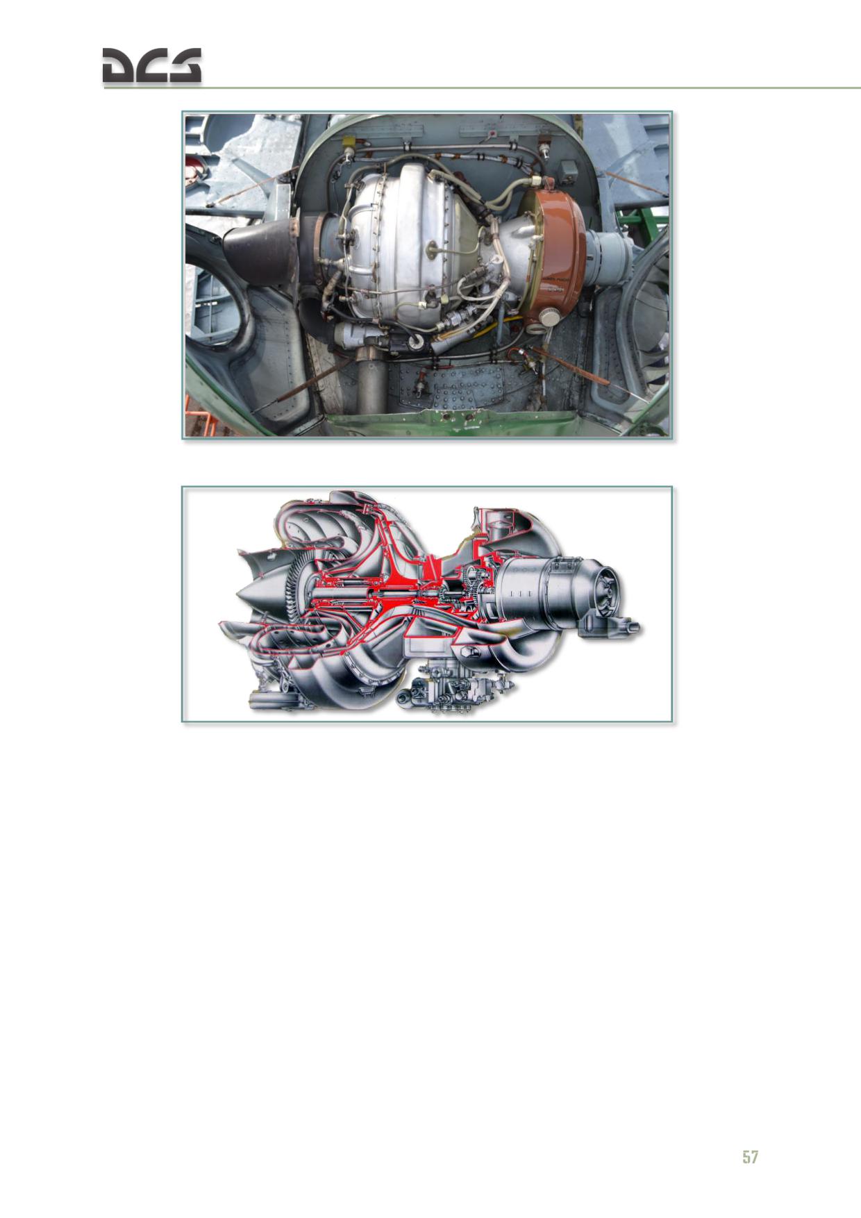
Fig. 4.6. AI-9V APU mounted on the helicopter
Fig. 4.7. AI-9V cutout
The start sequence is automated and controlled by the APD-9V start control box
(located in the radio compartment), which produces control signals to engage and
disengage components of the system according to the programmed sequence.
The APU start control box controls:
APU ground start;
APU false start;
APU crank cycle;
APU shutdown at any time during the start, false start or crank cycle.
The AI-9V starting circuits are protected by the START APU - “START” and “IGNIT”
(ЗАПУСК ТУРБОАГРЕГАТ "ЗАПУСК" и "ЗАЖИГАН.") circuit breakers on the right
circuit breaker console.
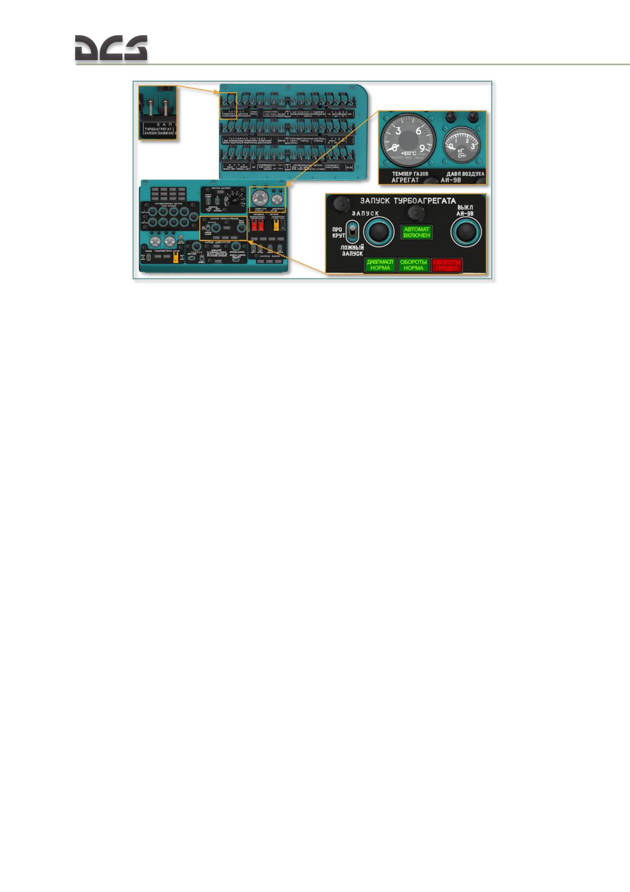
Fig. 4.8. APU start control panel and circuit breakers
The starting system is operated by the START-CRANK-FALSE START ("ЗАПУСК-
ПРОКРУТ-ЛОЖНЫЙ ЗАПУСК") switch, the START
("ЗАПУСК") and APU OFF
("ВЫКЛ. АИ-9В") pushbuttons on the APU start control panel.
APU exhaust gas temperature is displayed by the APU EGT ("ТЕМПЕР. ГАЗОВ")
gauge. The pressure in the APU main bleed air channel is displayed by the APU air
pressure ("ДАВЛ. ВОЗДУХА") gauge.
The lamp indicators on the APU start control panel include the APU OIL PRESSURE
NORMAL ("ДАВЛ. МАСЛА НОРМА") light, APU RPM NORMAL ("ОБОРОТЫ НОРМА")
light, and APU OVERSPEED ("ОБОРОТЫ ПРЕДЕЛ") light.
When the starting sequence is engaged, the APU AUTOSTART
("АВТОМАТ.
ВКЛЮЧЕН") light illuminates.
4.3. Drive system
The VR-14 main transmission is mounted on top of the center fuselage deck. The
mounting struts attach at four points to the fuselage. The transmission is essentially
a reduction gearbox designed to transmit the sum power of both TV3-117VM engines
to the main rotor, tail rotor, oil cooler fan, and accessories (two hydraulic pumps,
two AC generators, two rotor tachometers, and an air compressor) at a reduced and
adjustable RPM. The drive system includes:
intermediate gearbox;
tail rotor gearbox;
transmission driveshafts;
rotor brake system.
The main transmission includes freewheeling clutches in the input quills to provide a
quick-disconnect of one or both engines in case of a power failure. This allows for
safe flight with one engine inoperative and allows main and tail rotors to rotate in
order to accomplish a safe autorotation landing.
58
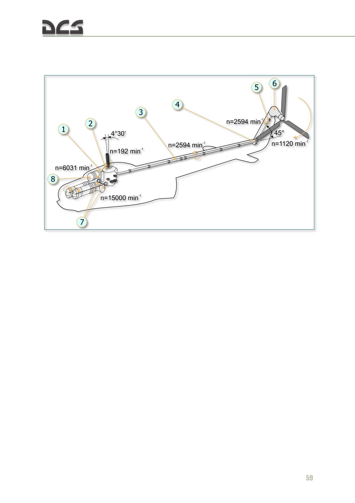
Magnetic chip detectors and warning lamps are provided to control accumulation of
metal shavings in the transmission oil system. An oil temperature probe and an oil
pressure sensor are incorporated.
Fig. 4.9. Helicopter drive system
1. Oil cooler driveshaft;
5. Rear tail rotor driveshaft section;
2. VR-14 main transmission;
6. Tail rotor gearbox;
3. Tail rotor driveshaft;
7. TV3-117VM engine driveshafts;
4. Intermediate gearbox;
8. Oil cooler fan.
The intermediate gearbox is designed to change the angle of the tail rotor
driveshaft axis by 45° to conform with the angle between the tail boom and vertical
stabilizer.
The tail rotor gearbox is designed to rotate the tail rotor at the required RPM. The
last linked section of the tail rotor driveshaft is coupled to the tail rotor gearbox input
flange. The tail rotor hub mounts on the tail rotor gearbox output flange. Tail rotor
pitch is changed by the control rod, located inside the output shaft.
The transmission driveshafts include the tail rotor driveshaft and oil cooler fan
driveshaft.
The tail rotor driveshaft is designed to pass the torque from the main transmission
via the intermediate gearbox and the tail rotor gearbox to the tail rotor. The main
transmission and intermediate gearbox are connected by the horizontal section of the
tail rotor driveshaft. The intermediate gearbox and tail rotor gearbox are connected
by the angled rear section of the tail rotor driveshaft housed inside the vertical
stabilizer.
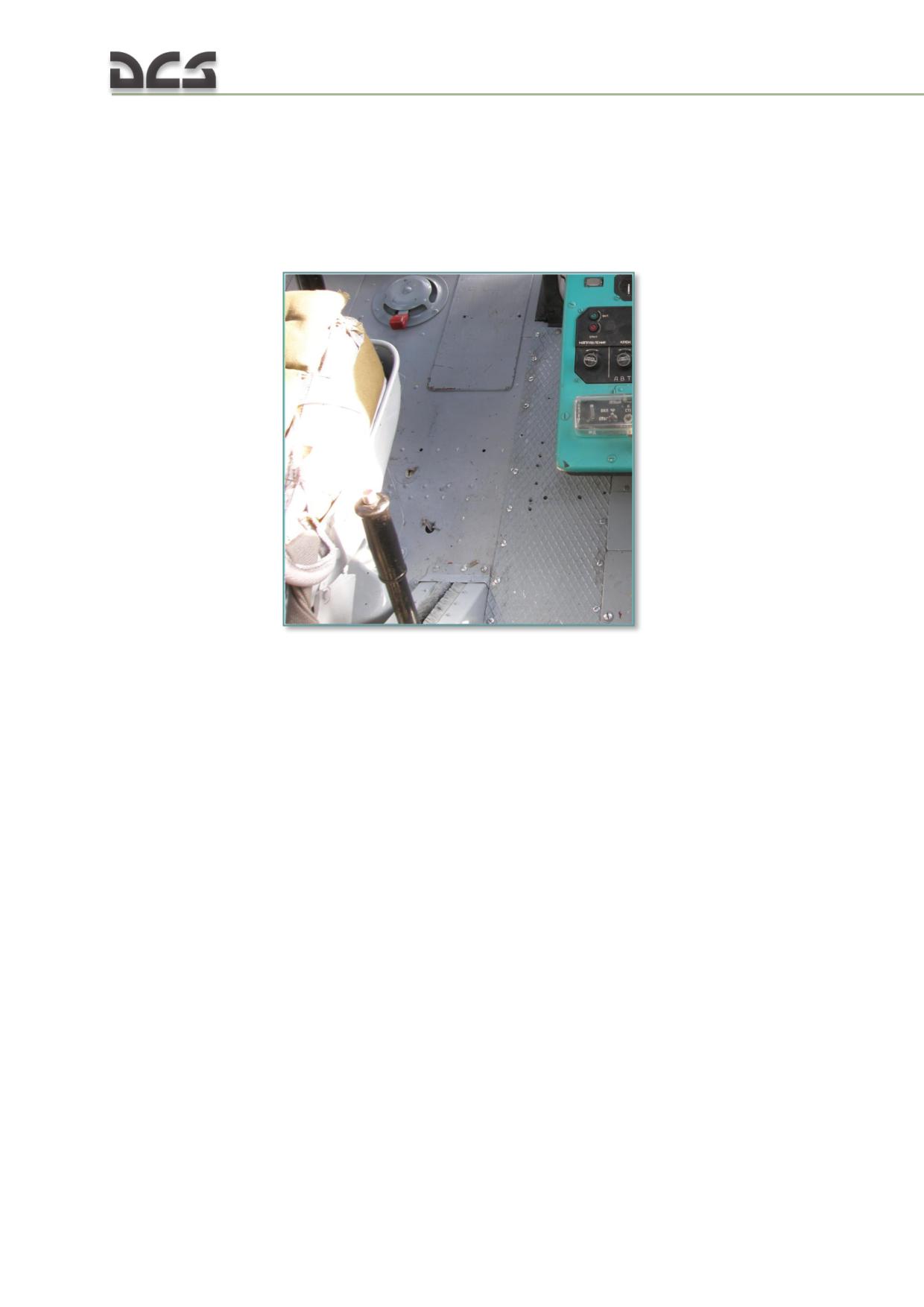
The oil cooler fan driveshaft transmits power from the transmission to the oil cooler
fan. The driveshaft is bolted to the transmission offset quill at the front of the
transmission. It connects to the oil cooler fan via a splined coupling.
The rotor brake reduces the time required to stop the main rotor. It is also used to
block the transmission while the helicopter is parked and during maintenance
operations.
Fig. 4.10. Rotor brake control lever
The rotor brake consists of a drum and shoes assembly mounted on the main
transmission tail rotor output quill. The brake is operated by a cable linkage from the
rotor brake control lever located to the right of the pilot's seat.
4.4. Air cooling system
The air cooling system includes the oil cooler fan assembly, distribution lines, and
cooling shrouds. The oil cooler fan cools the oil in the engine and transmission oil
coolers, the AC generators, the hydraulic pumps, and the air compressor. The oil
cooler fan assembly mounts over the rear section of the engine compartment as part
of a common nacelle. The oil cooler fan collects air via a dedicated oil cooler fan
inlet.
60
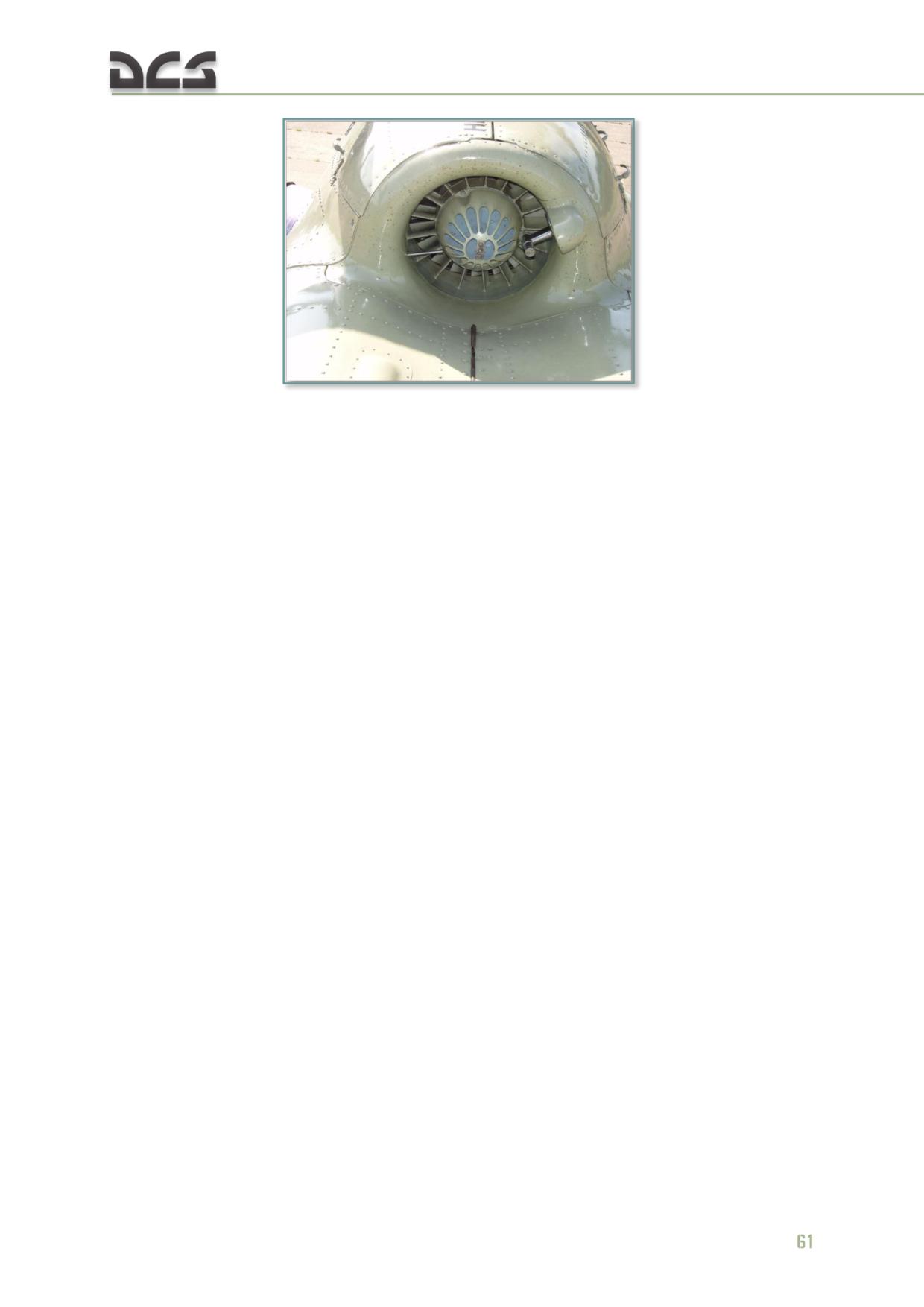
Fig. 4.11. Oil cooler fan
The fan cools the oil in the engine and transmission by blowing air directly through
the oil coolers. Hot air vents from the transmission compartment via an exhaust
shroud at the rear of the oil coolers. The remainder of the air passes through
protective shrouds to flexible lines to cool the generators, hydraulic pumps, and the
air compressor.
5
COCKPIT SYSTEMS AND CONTROLS
5. COCKPIT SYSTEMS AND CONTROLS
The cockpit includes control panels with various systems and equipment (Cockpit
layout), flight controls, Powerplant and Helicopter systems controls and indicators,
Flight data and Navigation Systems controls and indicators.
The helicopter's cockpit systems and controls suite provides for:
a) flight control and navigation in day and night time conditions in visual or
instrument meteorological conditions;
b) control of engine, transmission, and flight performance.
c) control of all helicopter systems.
DCS provides pop-up "hints" to identify all of the interactive cockpit controls/switches
to ease familiarization with helicopter systems. To see the hint for a particular
control/switch, simply hover the mouse over it in the cockpit. Pop-up hints can be
enabled/disabled in the OPTIONS menu.
In the simulation, the mouse can be used to perform the following actions:
- left-click to engage a switch/button;
- right-click or left-click to manipulate a multi-position switch;
- rotate the mouse wheel or left-click, hold and drag the mouse to turn a rotary
switch/dial.
When the mouse cursor is placed over an interactive cockpit control, the yellow cross
icon changes color to green to indicate the control is clickable and changes shape to
indicate whether the control is discrete or rotary type. All of the mouse clickable
controls are provided a keyboard shortcut, which can be found in the INPUT
OPTIONS menu. Keyboard shortcuts are also provided in this manual in blue color.
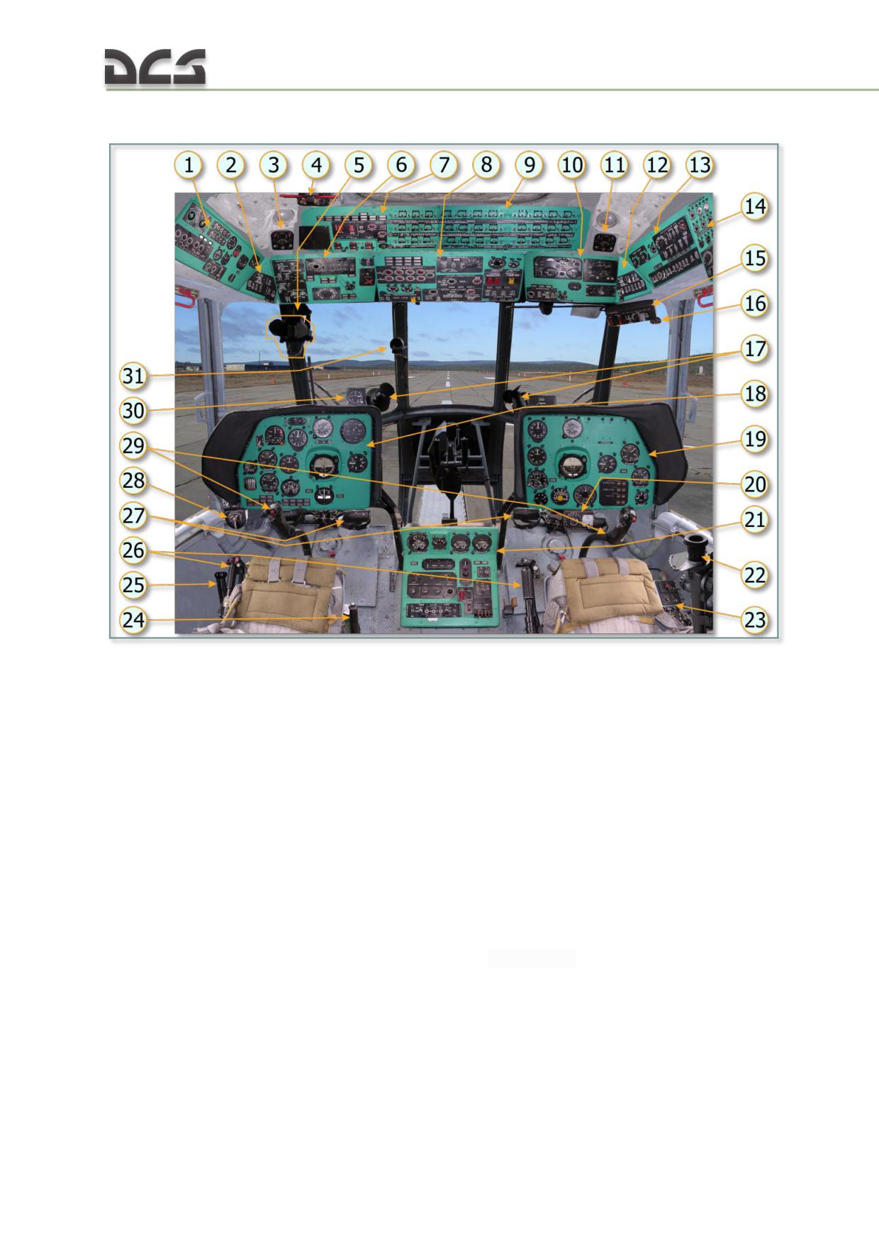
5.1. Cockpit layout
Fig. 5.1. Cockpit layout
1. Left side console
17. Cockpit funs
2. Left triangular panel
18. Left instrument panel
3. Intercommunications set SPU-7 control boxes
19. Right instrument panel
for pilot
20. ЭСБР-3П/А (ESBR-3P/A) Electrical release
4. Fuel shutoff levers (fuel cut-off triggers) of the
control box
engines
21. Center console
5. Pilot Sight PKV
22. Copilot Sight ОПБ-1р (OPB-1R) - bombing
6. Left overhead console
sight, not modeled
7. Left circuit breaker console
23. Right auxiliary panel
8. Center overhead console
24. Rotor brake lever
9. Right circuit breaker console
25. Throttle handles
10. Right overhead console
26. Collective control handle
11. Intercommunications set SPU-7 control boxes
27. Anti-torque pedals
for copilot
28. Pitot tube selector
12. Right triangular panel
29. Cyclic control stick
13. Right side console
30. G-load indicator
14. Right rear console
31. Magnetic compas КИ-13 (KI-13)
15. Copilot's weapons control panel
16. Outdoor temperature gauge
64
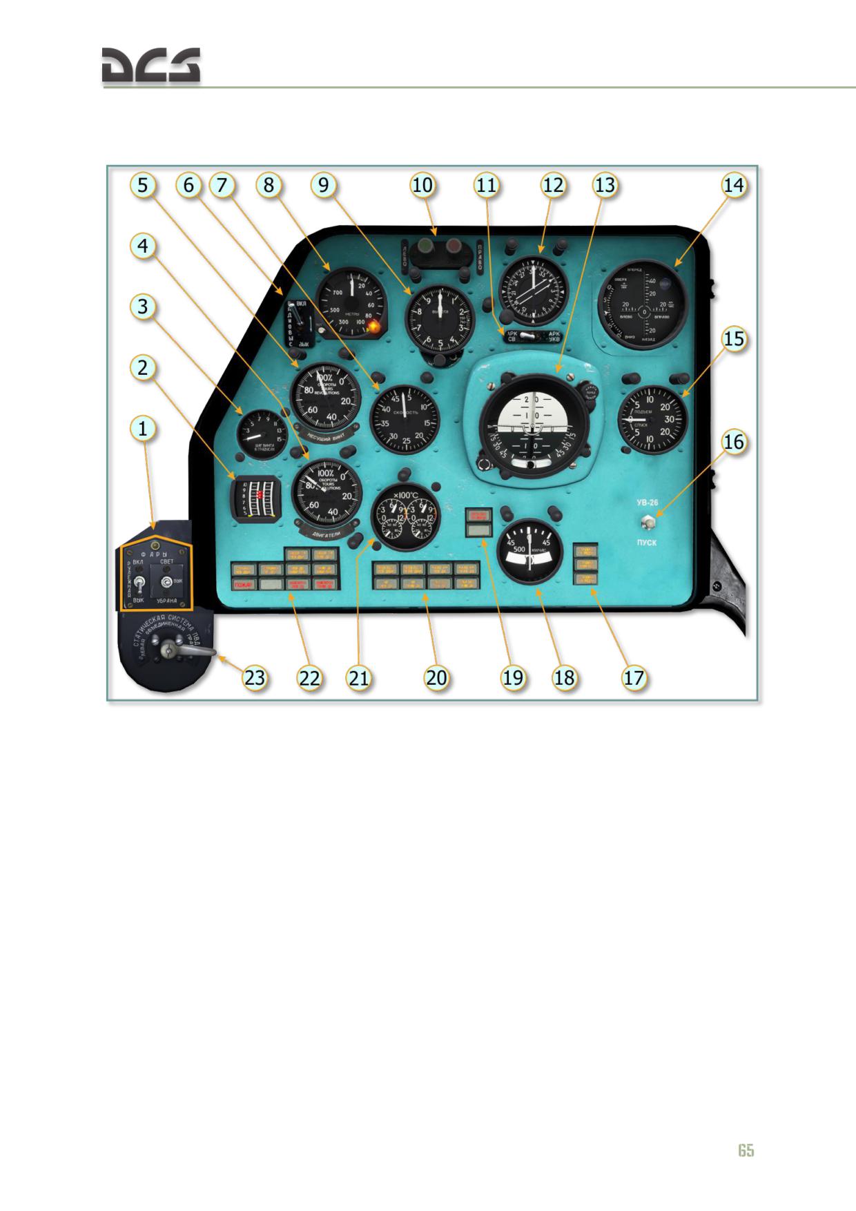
DIGITAL COMBAT SIMULATOR Mi-8МТV2
5.1.1. Left Instrument Panel (Pilot)
Fig. 5.2. Left instrument panel (pilot)
1. Pilot's landing/search and taxi light controls
11. АРК СВ-УКВ (ADF HF-VHF) switch
2. УР-117М (UR-117M) engine pressure radio
12. УГР-4УК (UGR-4UK) directional gyro
(EPR) indicator
13. АГБ-3К (AGB-3K) attitude indicator
3. ИП-21 (IP-21) main rotor pitch angle indicator
14. Hover and low speed control indicator
4. ИТЭ-2Т (ITE-2T) two-pointer engine
15. ВР-30МК (VR-30MK) vertical velocity indicator
tachometer indicator
16. Manual flare dispersion button at UV-26
5. ИТЭ-1Т (ITE-1T) main rotor tachometer
countermeasures
indicator
17. Annunciators (lights)
6. Radar altimeter switch
18. ЭУП-53 (EUP-53) turn indicator
7. УС-450К (US-450K) airspeed indicator
19. "СЕТЬ ПИТ.ОТ АКК" ("BATTARY IN USE")
8. УВ-5M (UV-5M) radar altimeter indicator
light (above) and “ОТАКАЗ 6201” (“6201 FAIL”)
9. ВД-10ВК (VD-10VK) pressure altimeter
(below)
indicator
20. Annunciators (lights)
10. ОПБ-1Р (OPB-1R) bomb sight course
21. 2УТ-6К (2UT-6K) exhaust gas temperature
indicator
indicator
22. Annunciators (lights)
23. Pitot tube selector
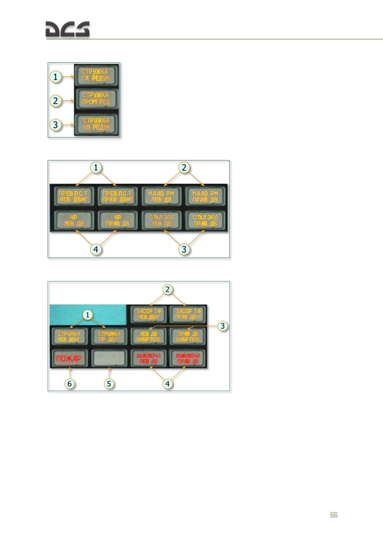
DIGITAL COMBAT SIMULATOR Mi-8МТV2
(17) Warning light:
1. Сhips in Main Gearbox
2. Сhips in Intermediate Gearbox
3. Сhips in Tail Rotor Gearbox
(20) Warning light:
1. Left (right) engine Free
Turbin Overspeeding
2. Left (right) engine Oil
Pressure is Low
3. Electronic Control left
(right) engine OFF
4. Emergency Power (ЧР -
Чрезвычайный Режим) left
(right) engine
(22) Warning light:
1. Сhips in left (right) engine Oil
2. Fuel Filter Clogging left
(right) engine
3. Left (right) engine Abnormal
vibration
4. Left (right) engine Excursion
Limit vibration
5. Light is not used
6. Fire
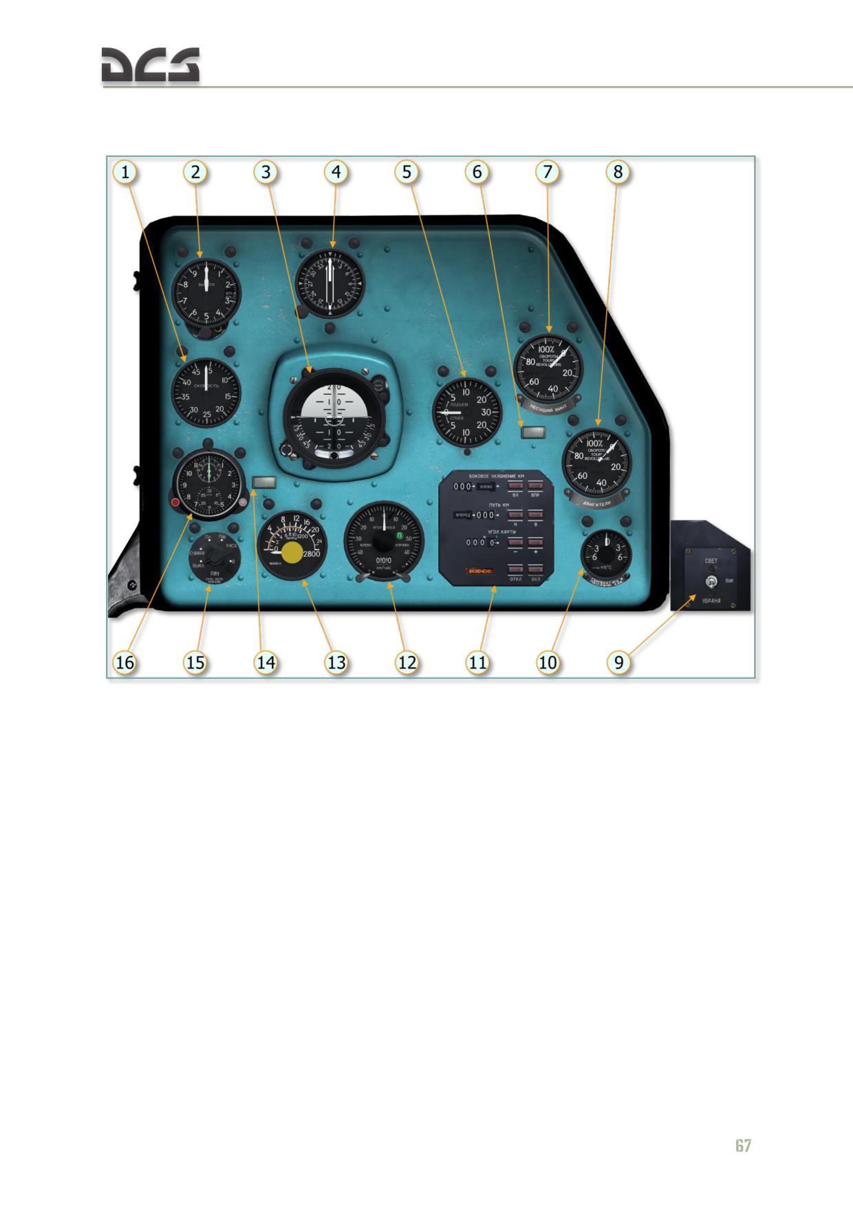
DIGITAL COMBAT SIMULATOR Mi-8МТV2
5.1.2. Right Instrument Panel (Copilot)
Fig. 5.3. Right instrument panel (copilot)
1. УС-450К (US-450K) airspeed indicator
9. Copilot's landing/search light switch
2. ВД-10ВК (VD-10VK) pressure altimeter
10. ТВ-1 (TV-1) cabin temperature indicator
indicator
11. ДИСС-15 (DISS-15) Doppler system
3. АГБ-3К (AGB-3K) attitude indicator
coordinate indicator
4. УГР-4УК (UGR-4UK) directional gyro
12. ДИСС-15 (DISS-15) Doppler system ground
5. ВР-30МК (VR-30MK) vertical velocity indicator
speed and drift indicator
6. “ДИСС ОТКАЗАЛ” Doppler system fail
13. БЭ-09К (BE-09K) fuel quantity indicator
annunciator
14. Low Fuel (270 L) annunciator
7. ИТЭ-1Т (ITE-1T) main rotor tachometer
15. П-8УК (P-8UK) fuel meter switch
indicator
АЧС-1 (AChS-1) clo
8. ИТЭ-2Т (ITE-2T) two-pointer engine
tachometer indicato

DIGITAL COMBAT SIMULATOR Mi-8МТV2
5.1.3. Center Console
Fig. 5.4. Center console
1. УИЗ-6 (UIZ-6) main transmission oil temp,
7. Р-863 (R-863) VHF radio frequency select
intermediate and tail rotor gearbox oil pressure
panel
indicator
8. Engine governor control panel
2. ТУЭ-48 (TUE-48) main transmission oil temp
9. Lamp test and electrical system backup
indicator
switches
3. УИЗ-3 (UIZ-3) left engine oil pressure and
10. АП-34Б (AP-34B) autopilot control panel
temp indicator
11. БУ-32-1 (BU-32-1) control unit for the СПУУ-
4. УИЗ-3 (UIZ-3) right engine oil pressure and
52 (SPUU-52) pitch limit system
temp indicator
12. ИН-4 (IN-4) trim indicator of the automatic
5. Р-863 (R-863) VHF radio manual/preset
flight control system
selector
6. Р-863 (R-863) VHF radio control panel
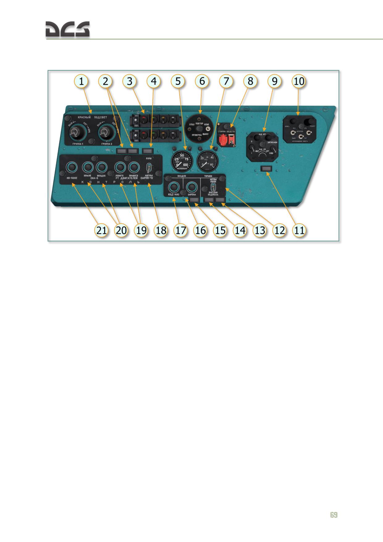
DIGITAL COMBAT SIMULATOR Mi-8МТV2
5.1.4. Left Side Console
Fig. 5.5. Left side console
1. Left side group 1/2 red lighting dimmers
10. П-503Б (P-503B) cockpit voice recorder (CVR)
2. “РТ ЛЕВ РАБОТАЕТ” “РТ ПРАВ РАБОТАЕТ”
control panel
LH/RH engine temp regulator operating
11. “ВКЛЮЧИ ЗАПАСНОЙ” (“Set Reserve”)
annunciators
annunciator
3. ЭП-662 (EP-662) signal flares control panel
12. External cargo auto release switch
4. “САРПП РАБОТАЕТ” flight data recorder (FDR)
13. “СТВОРКИ ОТКРЫТЫ” (“Doors open”)
operating annunciator
annunciator
5. МВУ-10К (MVU-10K) pneumatic system air
14. “ЗАМОК ОТКРЫТ” (“Shackle open”)
pressure gauge
annunciator
6. РИ-65Б (RI-65B) voice warning system remote
15. “СИРЕНА ВКЛЮЧЕНА” (“Horn on”)
control panel
annunciator
7. МА-60К (MA-60K) air pressure gauge for the
16. Air horn button
landing gear wheel brake system
17. Code NAV lights button
8. Control panel 484 of “device 6201” (IFF
18. FDR power switch
responder)
19. LH/RH engine temp regulator test buttons
9. Control panel 485 of “device 6201” (IFF
20. EGT gauge ground and air test buttons
responder)
21. ИВ-500Е (IV-500E) engine vibration indicator
test button
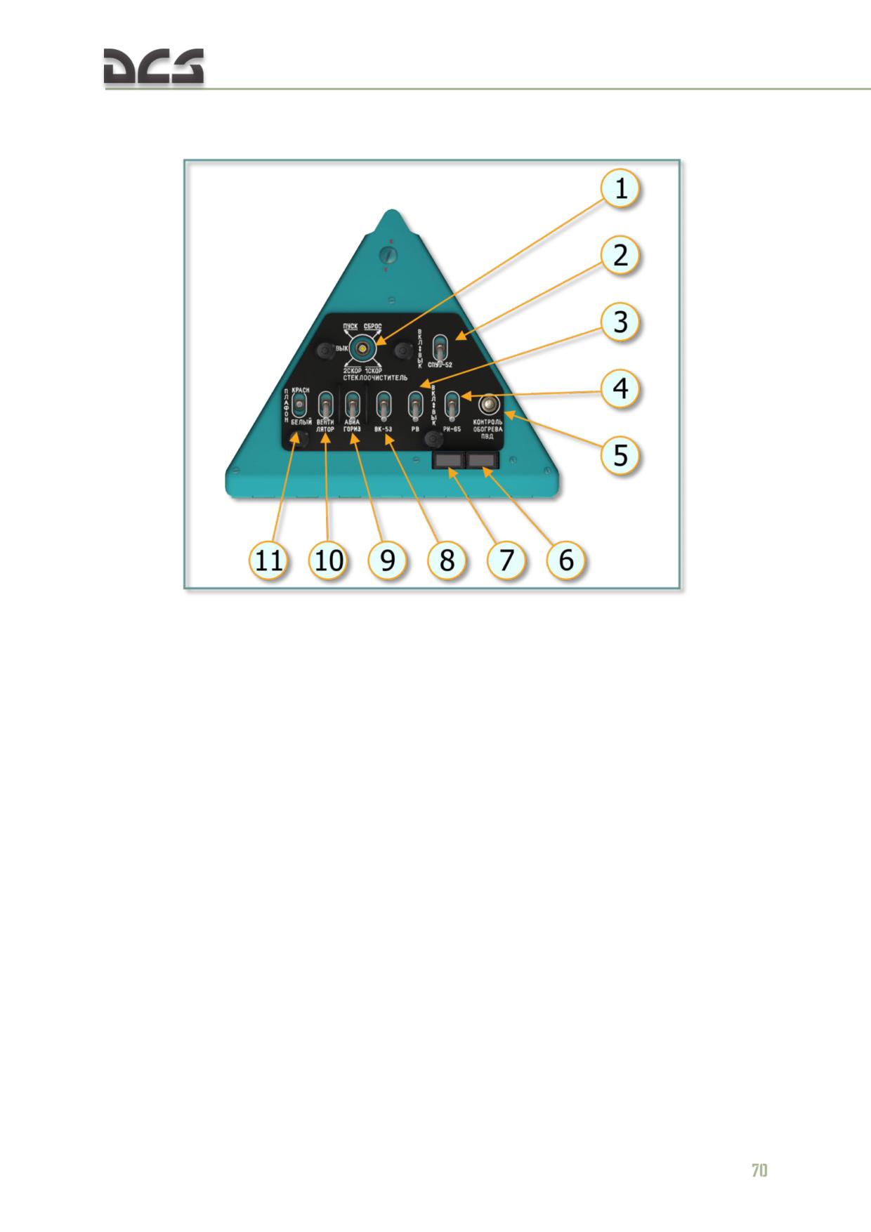
DIGITAL COMBAT SIMULATOR Mi-8МТV2
5.1.5. Left Triangular Panel
Fig. 5.6. Left triangular panel
1. Windshield wiper switch
7. “ВКЛЮЧИ РИ-65” (Turn on VWS) annunciator
2. СПУУ-52 (SPUU-52) tail rotor pitch limit system
8. ВК-53 (VK-53) gyro correction cutout power
power switch
switch
3. Radar altimeter power switch
9. Left attitude indicator power switch
4. РИ-65 (RI-65) voice warning system (VWS)
10. Fan power switch
power switch
11. Dome light switch
5. Pitot tube heating test switch
6. “ОБОГРЕВ ИСПРАВЕН” (Heater OK)
annunciator
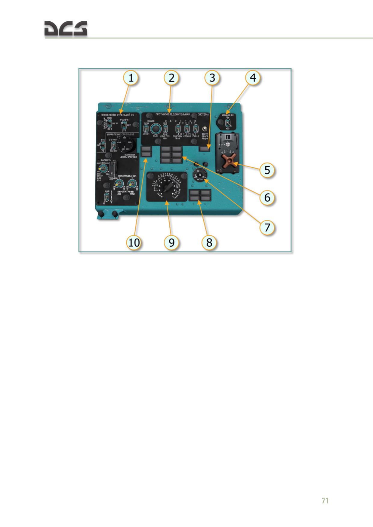
DIGITAL COMBAT SIMULATOR Mi-8МТV2
5.1.6. Left Overhead Console
Fig. 5.7. Left overhead console
1. Pilot’s weapons control panel
6. Anti-ice system annunciator panel
2. Anti-ice system control panel
7. АФ1-150 (AF1-150) ammeter
3. “ОБОГРЕВ ИСПРАВЕН” (Anti-ice normal)
8. Section 1…4 annunciator panel
annunciator
9. Ammeter load current selector switch
4. Р-863 (R-863) VHF radio FM/AM switch
“ОБЛЕДЕН” (Icing) “ПОС ВКЛЮЧЕНА” (Anti-ice
5. Р-863 (R-863) VHF radio channel selector
ON) annunciators
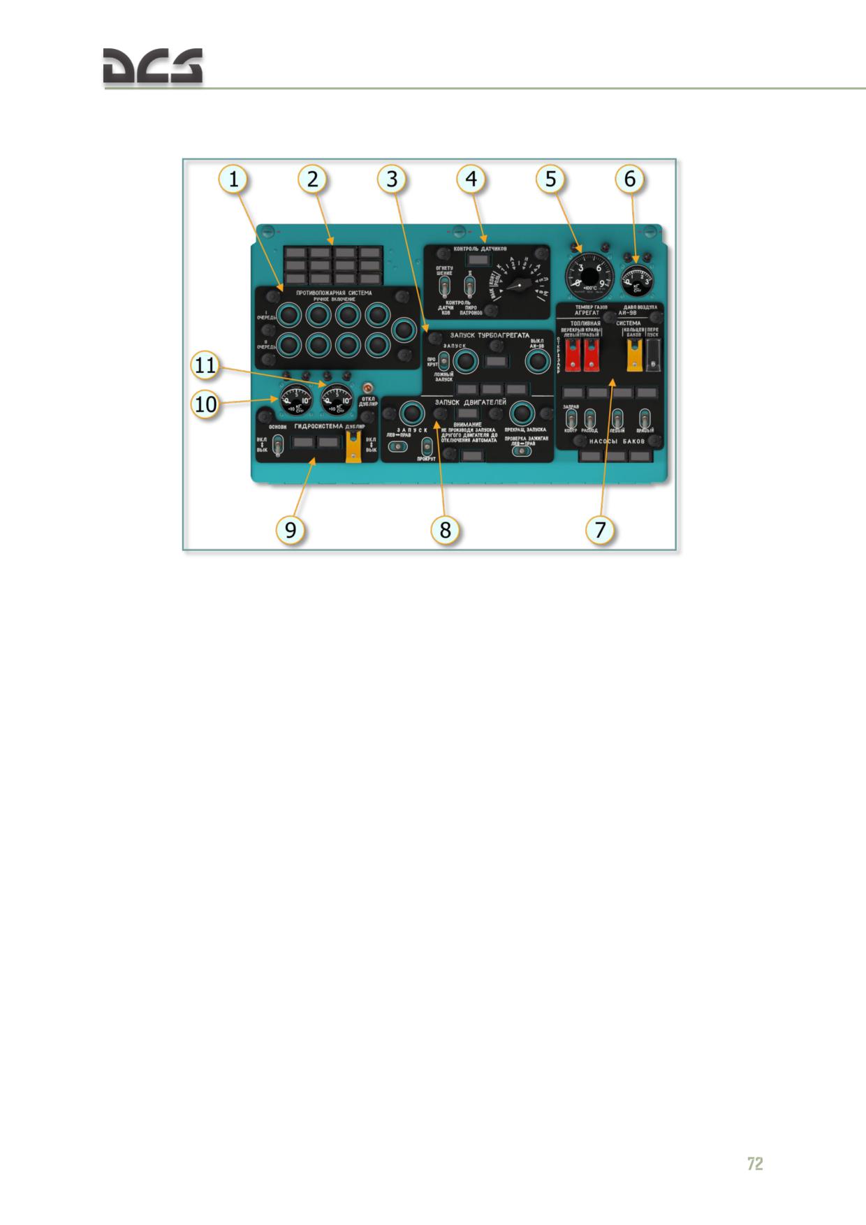
DIGITAL COMBAT SIMULATOR Mi-8МТV2
5.1.7. Center Overhead Console
Fig. 5.8. Center overhead console
1. Fire protection system panel
7. Fuel system control panel
2. Fire protection system panel annunciators
8. Engine start control panel
3. APU start control panel
9. Hydraulic system control panel
4. Fire protection system test panel
10. Main hydraulic system pressure indicator
5. APU EGT indicator
11. Reserve hydraulic system pressure indicator
6. APU air pressure indicator
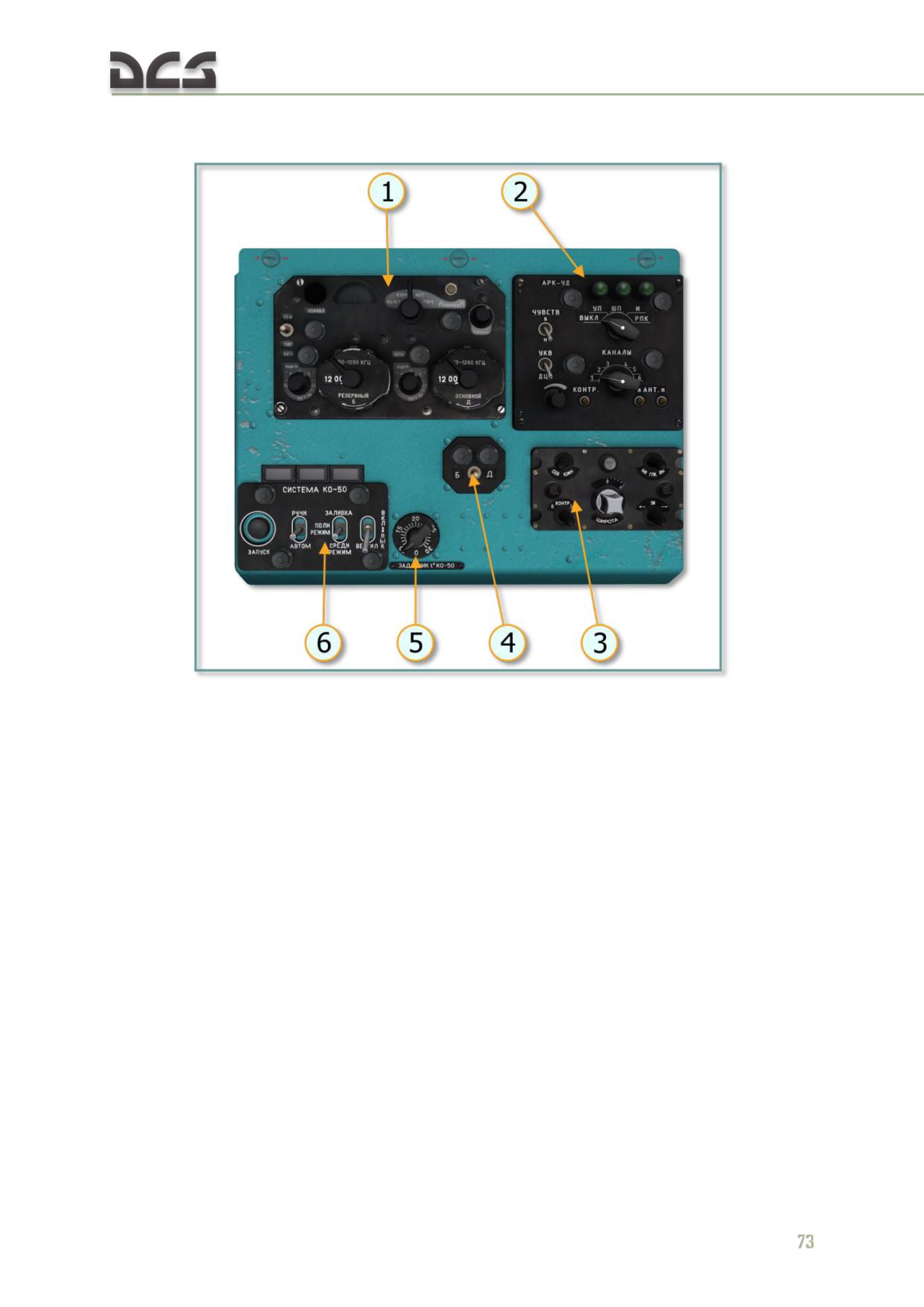
DIGITAL COMBAT SIMULATOR Mi-8МТV2
5.1.8. Right Overhead Console
Fig. 5.9. Right overhead console
1. АРК-15 (ARK-15) ADF control panel
4. АРК-15 (ARK-15) frequency selector
2. АРК-УД (ARK-UD) ADF control panel
5. КО-50 (KO-50) heater temp regulator switch
3. ПУ-26 (PU-26) control panel of the ГМК-1А
6. КО-50 (KO-50) heater control panel with
(GMK-1A) gyrocompass system
annunciators
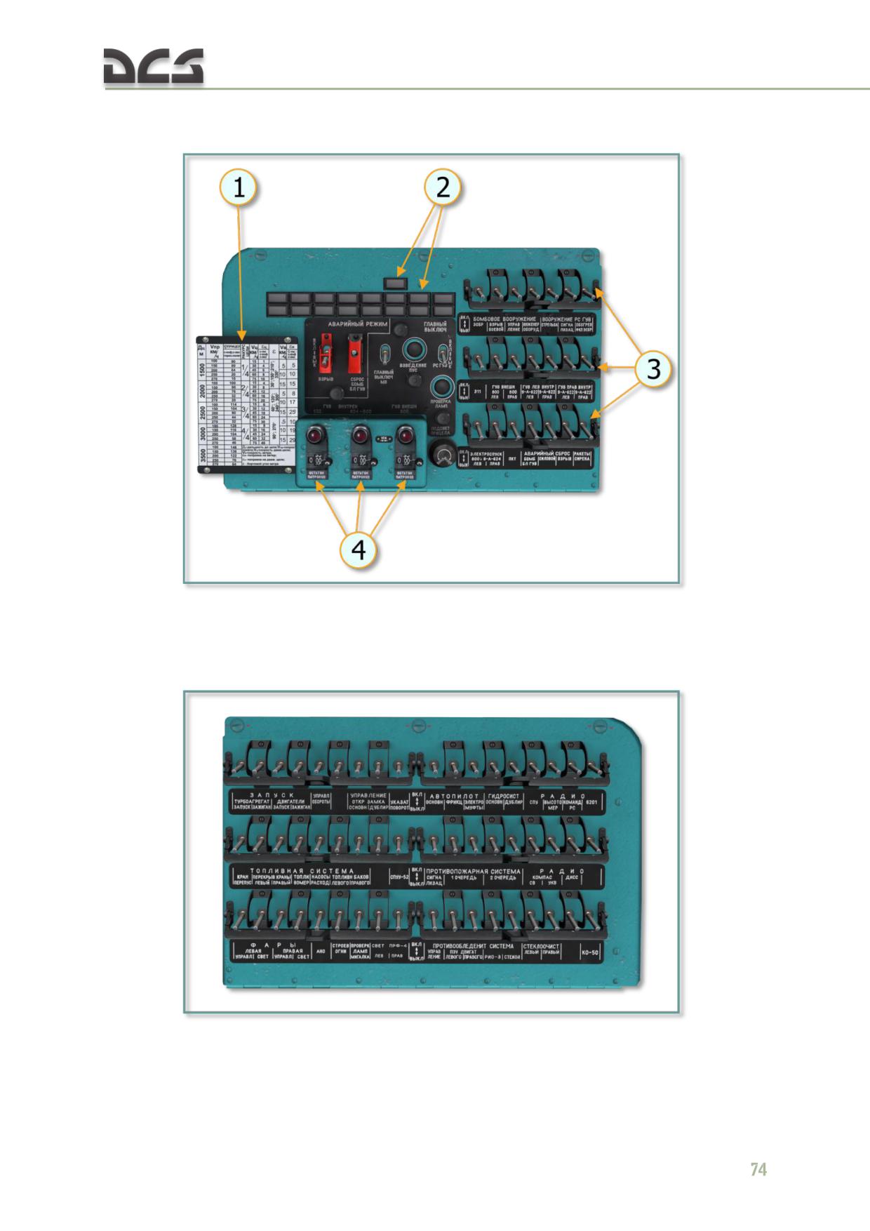
DIGITAL COMBAT SIMULATOR Mi-8МТV2
5.1.9. Circuit Breaker Consoles
Fig. 5.10. Left circuit breaker console
1. Aiming correction table
3. Weapon systems circuit breakers
2. Weapons arming panel
4. Remaining ammunition indicators
Fig. 5.11. Right circuit breaker console
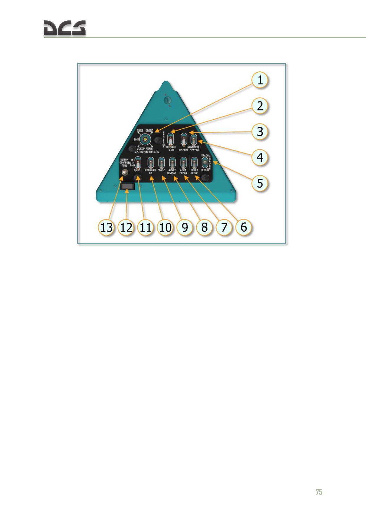
5.1.10. Right Triangular Panel
Fig. 5.12. Right triangular panel
1. Windshield wiper switch
8. Astrocompass power switch
2. ДИСС-15 (DISS-15) Doppler system and
9. ГМК-1 (GMK-1) gyrocompass system power
ЯДРО-1А (Yadro-1A) radio control panel lighting
switch
switch
10. Yadro-1A HF radio power switch
3. Microphone power switch
11. Doppler system power switch
4. VHF-ADF interlock switch
12. “ОБОГРЕВ ИСПРАВЕН” (Heater OK)
5. Dome light switch
annunciator
6. Fan power switch
13. Pitot tube heating test switch
7. Right attitude indicator power switch
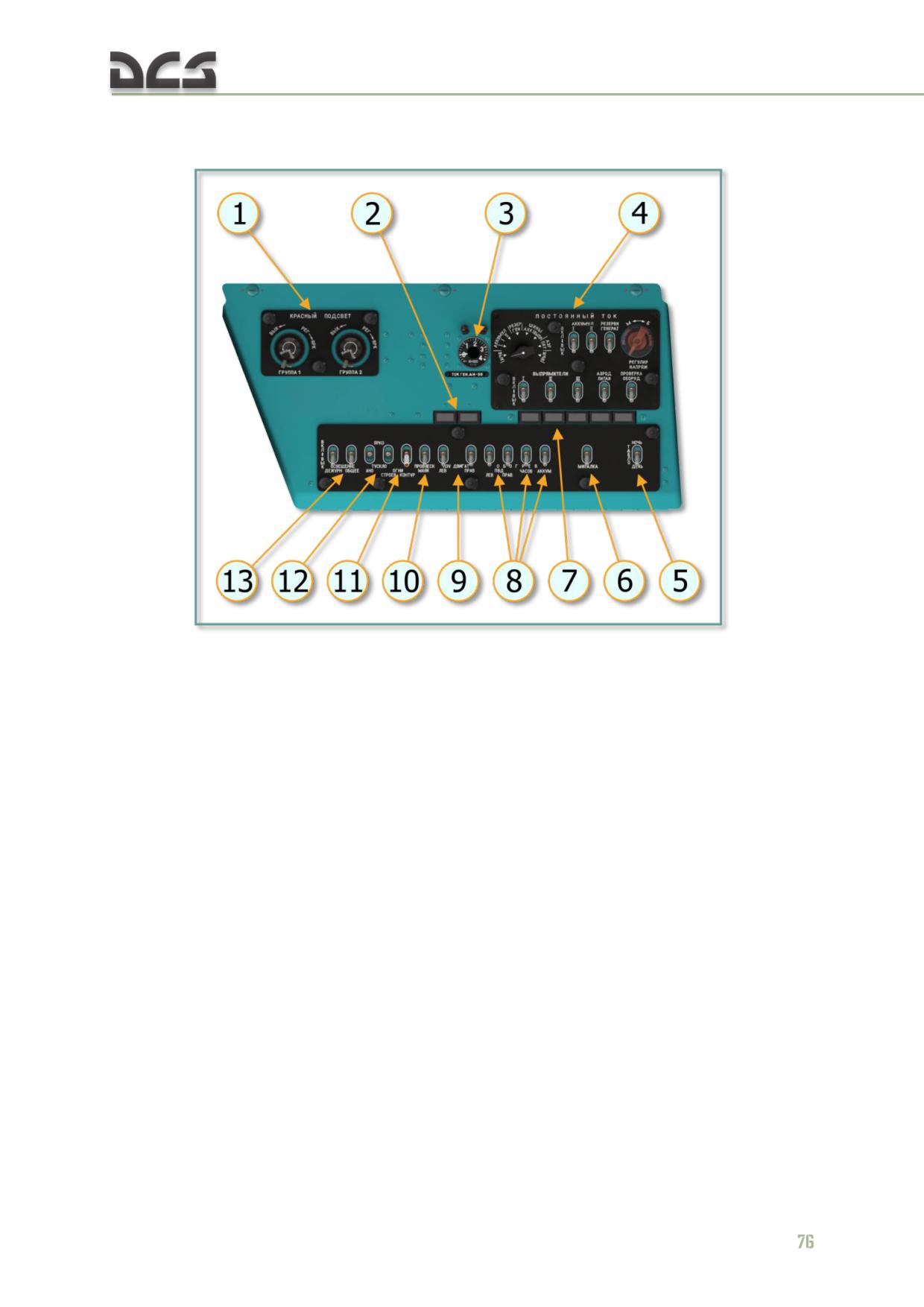
DIGITAL COMBAT SIMULATOR Mi-8МТV2
5.1.11. Right Side Console
Fig. 5.13. Right side console
1. Right side group 1/2 red lighting dimmers
8. LH/RH pitot tube, clock, and battery heating
2. “ЛЕВ/ПРАВ ПЗУ ВКЛЮЧЕН”(L/R Dust
switches
Protection ON) annunciators
9. L/R engine dust protection switches
3. APU generator load indicator
10. Strobe light switch
4. DC power control panel
11. Rotor tip and formation light switches
5. Annunciators brightness switch
12. Navigation and formation lights brightness
6. Warning blinker switch
switches
7. Rectifiers, external power, and BIT
13. General and standby cabin lighting switches
annunciators
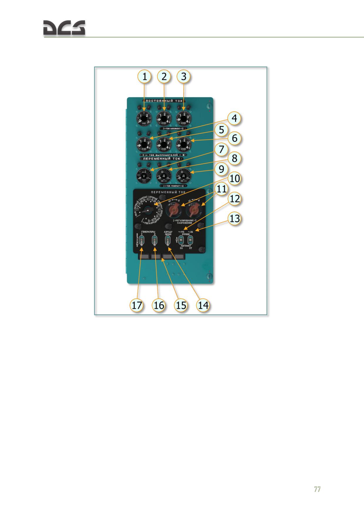
DIGITAL COMBAT SIMULATOR Mi-8МТV2
5.1.12. Right Rear Console
Fig. 5.14. Right rear console
1. DC voltmeter
11. AC voltage control rotary 1/2
2. DC battery 1 ammeter
12. Inverter 1 MAN/AUTO switch
3. DC battery 2 ammeter
13. Inverter 2 MAN/AUTO switch
4. AC rectifier 1 voltmeter
14. External power switch
5. AC rectifier 2 voltmeter
15. Generator 1, 2 fail; External power, PO-500
6. AC rectifier 3 voltmeter
heater annunciators
7. AC generator voltmeter
16. Generator 2 switch
8. AC generator 1 ammeter
17. Generator 1 switch
9. AC generator 2 ammeter
10. AC power control panel
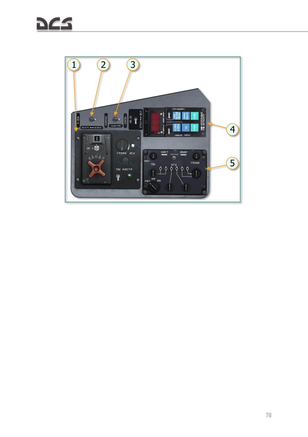
DIGITAL COMBAT SIMULATOR Mi-8МТV2
5.1.13. Right Auxiliary Panel
Fig. 5.15. Right auxiliary panel
1. Р-828 (R-828) radio control panel
4. УВ-26 (UV-26) countermeasures control panel
2. Р-828 (R-828) radio power switch
5. Yadro-1I HF radio set control panel
3. Р-828 (R-828) ANT-ADF switch
DIGITAL COMBAT SIMULATOR Mi-8МТV2
5.2. Flight controls
The helicopter is equipped with lateral, longitudinal, integrated collective pitch-
throttle, and directional flight control subsystems. Control inputs are transferred from
the cockpit to the rotor blades by mechanical linkages and hydraulic servos. Cables
are utilized in the rotor brake system and partially for tail rotor pitch control. Pilot
control is assisted by an automatic flight control system (AFCS) with an integrated
four channel autopilot, the hydraulic flight control servos, and pitch, roll, and yaw
trim systems. Both the pilot and copilot have collective, cyclic, and directional
controls, which are carried by mechanical linkage to the first and second stage
control units which combine, sum, and couple the cyclic, collective, and yaw inputs.
Resultant output signals are boosted and routed to the main and tail rotors through
mechanical linkages with the hydraulic servos.
Force centering devices are incorporated in the cyclic control system. The devices
furnish a force gradient or “feel” to the cyclic sticks. The farther the stick is deflected,
the more force is applied. A TRIM DISENGAGE button is located on the pilot and
copilot cyclic stick grips. Pressing and holding the TRIM DISENGAGE button will
immediately reduce the forces on stick to zero. Releasing the button reengages the
trim.
5.2.1. Cyclic Control System
Lateral and longitudinal control of the helicopter is by movement of the cyclic sticks
through push rods, bellcranks, and servos to the main rotor swashplate. Movement
in any direction tilts the plane of the main rotor blades in the same direction, thereby
causing the helicopter to move in that direction.
The pilot's (left) and copilot's (right) cyclic control sticks are nearly identical in design
and construction and are installed symmetrically on the cockpit floor relative to the
longitudinal axis of the helicopter.
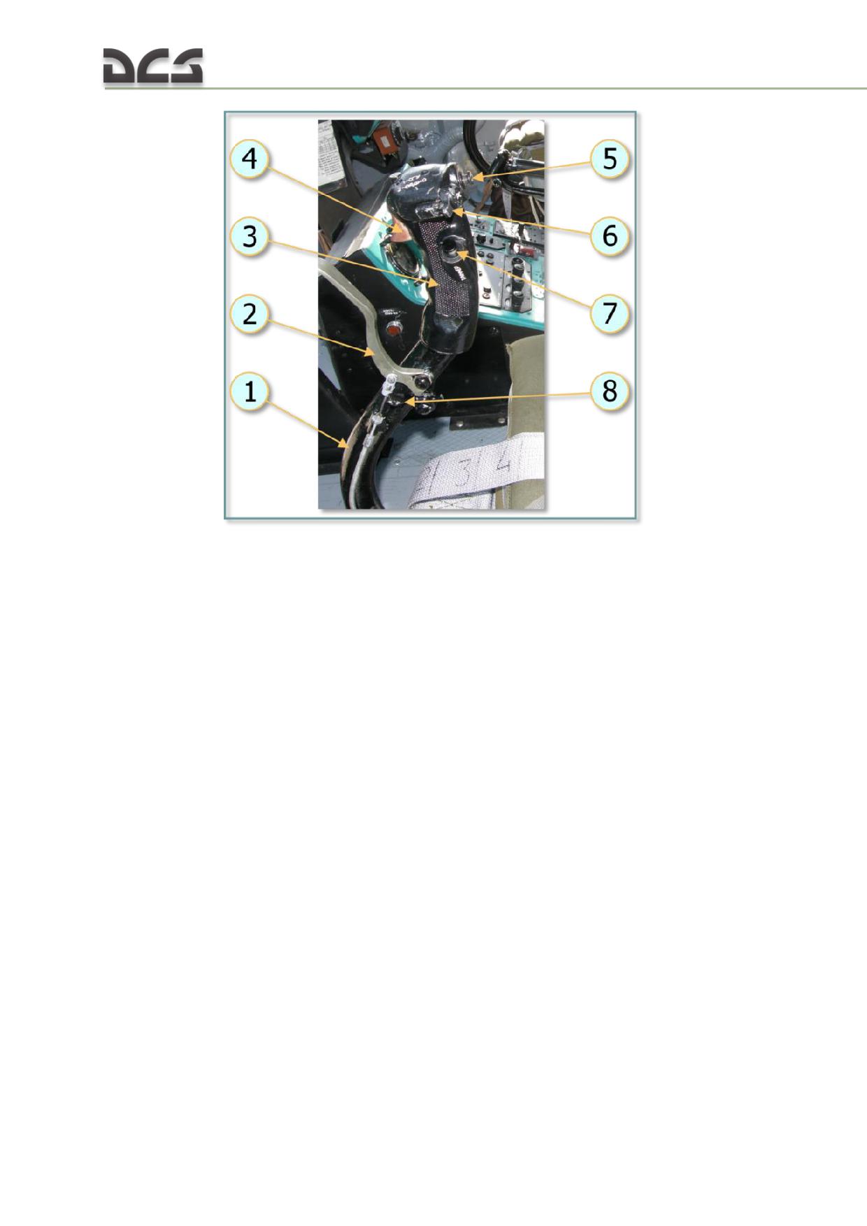
Fig. 5.16. Pilot's cyclic control stick
The cyclic control stick is constructed out of a shaped metal tube assembly (1) with a
hard rubber hand grip (3), which includes four buttons: ICS/RADIO keying button
(trigger position) (4), Autopilot OFF button (5), FIRE button (6), TRIM button (7).
The pilot's (left) cyclic also includes a wheel brake control lever (2) and a latch to
maintain it in the locked position (8).
Longitudinal stop: A hydraulic cylinder and mechanical stop are included in the longitudinal control
linkage to limit swashplate aft tilt to a maximum of 2º12' when the helicopter is on the ground or
taxiing. The stop is controlled by weight-on-wheels microswitches mounted on the main landing gear
strut supports. As the pilot pulls back on the cyclic, the longitudinal stop causes a sharp increase in
the force required to move the stick when the swashplate aft tilt reaches 2º12'. As the helicopter lifts
off the ground, the microswitch contacts open and the stop disengages, releasing the limit on aft
swashplate tilt.
5.2.2. Directional Control System
The directional control system is operated by the pilot or copilot pedal assemblies.
From the pedals to the directional servo, the control linkage consists of a system of
push/pull rods and bellcranks. Cables are used to pass control inputs to the tail rotor
gearbox. The pitch change mechanism for the gearbox consists of a chain, sprocket,
and worm gear, which extends or retracts the pitch control rod. Rod movement is
transmitted via the pitch change links to the blade grips, resulting in a change of
blade angle. Pushing the left pedal forward causes the pitch control rod to retract.
The blade pitch angle decreases and the helicopter turns to the left. Pushing the
right pedal forward extends the pitch control rod, increasing the blade pitch angle,
and the helicopter turns to the right. Right pedal movement is limited by a moveable
stop (pitch limiter) system which uses air density and temperature to adjust the
80
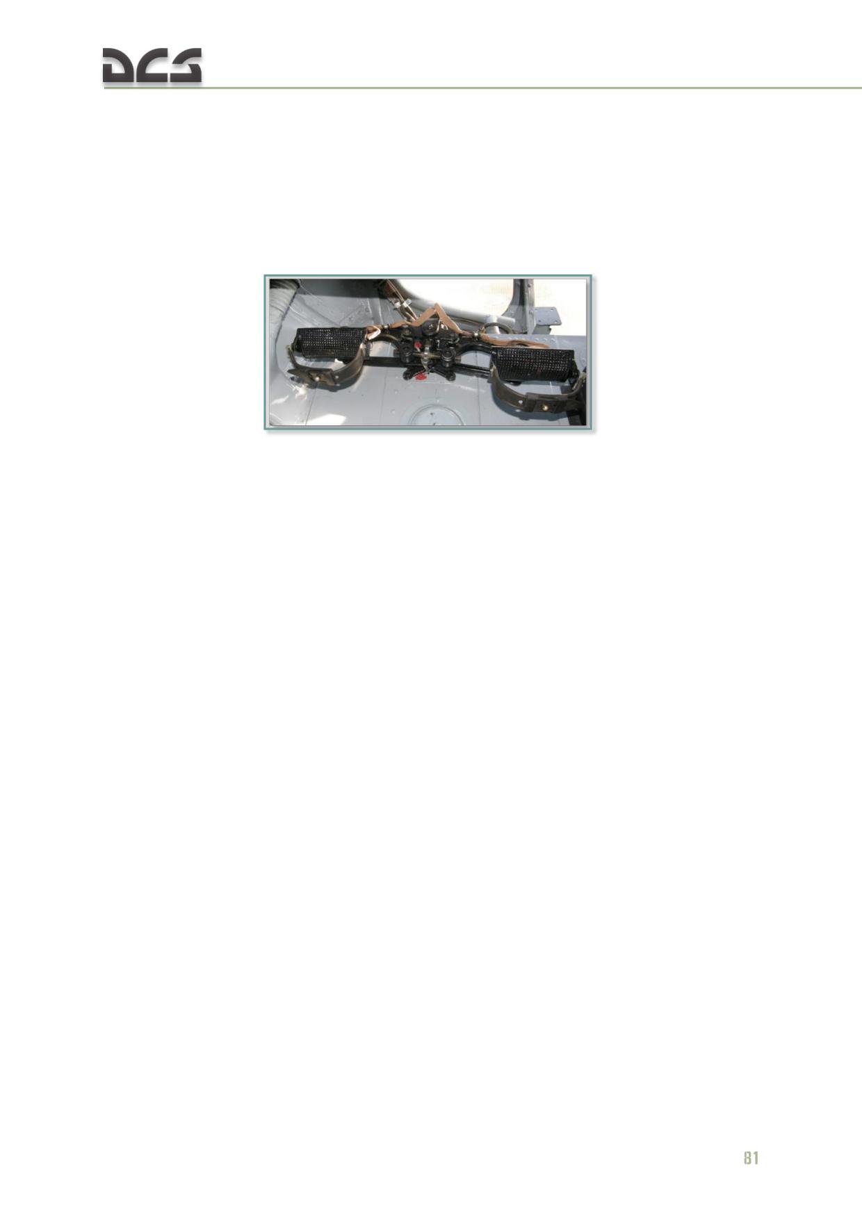
maximum tail rotor pitch angle and prevent overloading the tail rotor and drive
system.
The pedals are mounted on a bracket on the cockpit floor in front of the seat. Pedal
adjusters are provided to adjust the pedal distance for individual comfort. The
adjustment range is ±2.9 inches. Microswitches are mounted in each sub-pedal
assembly to allow the pilot to introduce directional control inputs while the autopilot
yaw channel is engaged.
Fig. 5.17. Anti-torque pedals
Force centering devices are incorporated in the directional control system. The
devices furnish a force gradient or “feel” to the pedals. The farther the pedals are
deflected, the more force is applied. A TRIM DISENGAGE button is located on the
pilot and copilot cyclic stick grips. Pressing and holding the TRIM DISENGAGE button
will immediately reduce the forces on the pedals to zero. Releasing the button
reengages the trim.
Tail rotor pitch limit system
The SPUU-52-1 tail rotor pitch limit system uses a linear actuator linked to a
mechanical stop to adjust the maximum tail rotor blade pitch angle within a range of
16º20' to 20º30'. The adjustment is based on air temperature and density:
increased density (low altitude or/and low temperature)results in a
decrease in the maximum blade pitch angle,
decreased density (high altitude or/and high temperature) results in a
increase in the maximum blade pitch angle.
When the system is disengaged, the stop resets and allows full right pedal travel.
The tail rotor pitch limit system is controlled and monitored via the SPUU-52-1
control panel. The panel is located in the right center area of the cockpit center
console. The main power switch for the system is located on the pilot’s left triangular
panel. When the system is disengaged, the red OFF lamp-button on the control panel
will illuminate. To engage the system, set the SPUU-52-1 main power switch to the
ON (up) position.
When the right pedal is fully pressed in, the AFCS heading channel disengages.
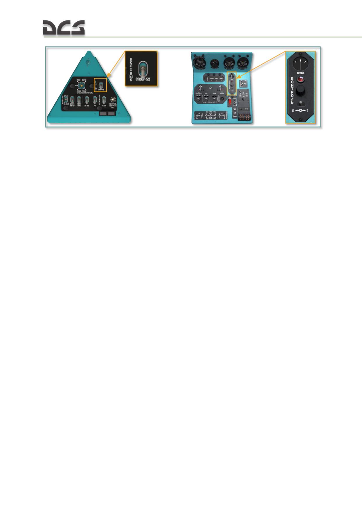
Fig. 5.18. SPUU-52-1 cockpit controls
If the SPUU-52-1 system fails in flight, the red OFF lamp-button on the control panel
will illuminate. In this case, the SPUU-52-1 main power switch on the left triangular
panel should be set to the OFF (down) position. This will set the limiter needle on the
SPUU-52-1 control panel to the full left position, indicating the removal of limits on
right pedal travel. Hover and landing with the limiter disengaged should be
performed as much as possible into the wind while avoiding large or sudden pedal
inputs.
Directional control system failure in flight
In case of directional control system failure in flight, the helicopter exhibits a strong
tendency to yaw left and, if roll angle is maintained neutral, a tendency to sideslip
right and turn left.
If the helicopter does not respond to pedal input, maintain an airspeed of 60-200
km/h and establish a right roll angle to maintain forward flight. Optimal airspeed is
approximately 150 km/h, which produces minimal sideslip with a roll angle of 5-7°
right in forward flight.
Test the helicopter response to pedal input throughout the pedal travel range in case
limited control is possible within a specific input range. Attempt to find a suitable
landing area allowing for a landing with an airspeed of 70-80 km/h.
Perform transitional maneuvers with gradual adjustments of collective control. When
raising collective, the cyclic requires adjustment to the right and increased right roll
angle. When lowering collective (for example to make a landing attempt), the cyclic
requires adjustment to the left and reduced right roll angle.
Perform turns and heading changes using roll control. Turns are best performed to
the left.
Once a suitable landing area is selected, begin a descent maintaining an airspeed of
150 km/h with 3-4 m/s descent rate.
At an altitude of 25 - 30 m, begin an aggressive deceleration. In the deceleration
avoid left yaw by measured and if necessary progressive reductions in collective
pitch.
At an altitude of 10 - 15 m, while continuing to decelerate, quickly reduce collective
pitch by 1.5 - 2.5° and level out any present roll. As collective is reduced, the
82
helicopter tends to yaw right and reduce slip (drift) angle. Control the rate of descent
and slip visually by referencing the ground and using collective pitch.
At an altitude of 3 - 4 m, increase collective pitch to establish a rate of descent of 1 -
2 m/s at touchdown. Keep in mind that yaw and slip/drift response occurs 1 - 2 sec
after collective increase.
After touchdown reduce collective pitch to minimum.
5.2.3. Collective Pitch Control System
The collective pitch control system includes integrated throttle and main rotor
collective pitch control linkages. The collective inputs raise or lower the swashplate
slide. This changes the pitch of the main rotor blades, causing an increase or
decrease in lift on the entire rotor disc. When the collective stick is moved upward,
main rotor collective pitch increases. At the same time, the engines increase to a
higher power setting. When the collective stick is moved downward, main rotor pitch
and engine power decreases. The collective control inputs reach the main engine
throttle controls via a series of bellcranks and push rods. The collective inputs to the
main rotor swashplate slide are routed via bellcranks and push rods to the collective
flight control servo and collective lever/rocker.
The collective sticks are mounted on the cockpit floor to the left of the pilot’s and
copilot's seats. A hydraulic clutch holds the stick securely in any position, allowing
the pilot to make smooth pitch adjustments and preventing the stick from creeping.
Ordinarily, the clutch is adjusted manually using the handwheel to allow the stick to
be moved, without releasing the clutch, with a force of 45 to 55 lb. The CLUTCH
RELEASE button activates the hydraulic clutch release system, allowing the stick to
be moved with a force no greater than 3.3 lb. When the button is released, the
clutch re-engages. The CLUTCH RELEASE button also disengages the autopilot
altitude channel.
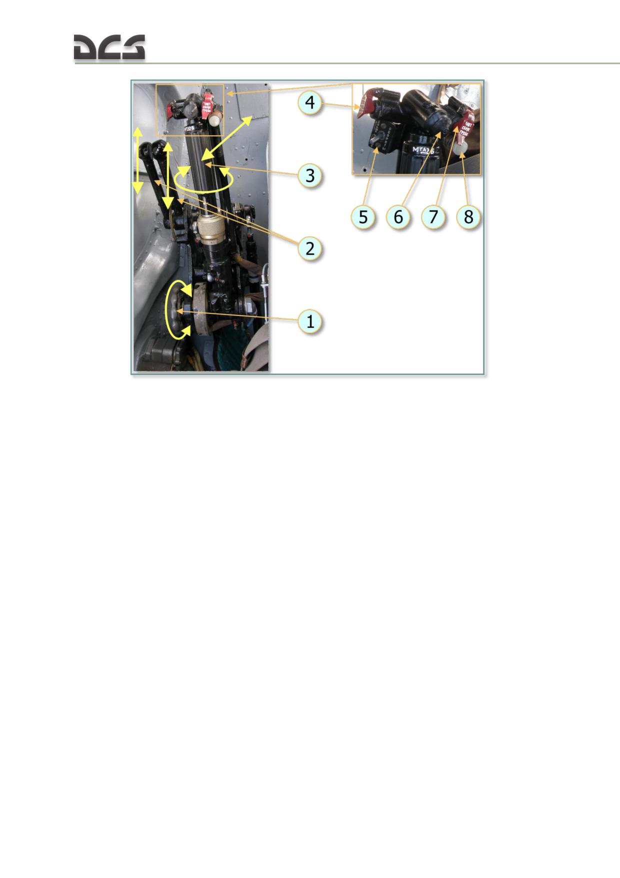
Fig. 5.19. Pilot's (left) collective control group
1. Hand wheel (friction adjust)
5. N2 trim INCR-DEC switch
2. Engine condition levers (ECLs)
6. Searchlight control button
3. Twist throttle
7. Tactical external stores jettison button
4. Emerg cargo release button
8. CLUTCH RELEASE button
The copilot’s collective stick is located to the left of the copilot seat. It is similar in
design to the pilot’s collective, but does not include a friction clutch, cargo release
buttons, or engine condition levers (ECLs).
Joint (dual) engine operation is controlled using the twist grip throttle control on the
pilot or copilot collective sticks. The throttle is rotated right (clockwise) from the
closed position through an idle detent, to fully open.
The engines are controlled individually by the pilot's ECLs. The ECLs vary the engine
compressor (N1) control lever (throttle) settings from minimum to maximum power
separately for each engine. They are used to control the engine power setting during
ground testing and in special flight conditions, such as failure of one engine. The
normal position of the ECLs is in the center detents. The engines can be brought to
takeoff power by moving the engine condition levers to the maximum settings.
The collective control system is a reserve, manual method of rotor RPM control.
Under normal conditions, rotor RPM is maintained automatically by the engine
governor system.
Transition between automatic and manual rotor RPM control is accomplished using
the twist throttle. When the throttle is fully open, the governor system automatically
maintains rotor RPM. Twisting the throttle left (counterclockwise) disengages
84
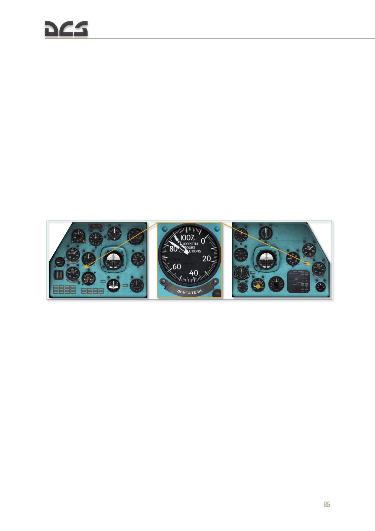
automatic RPM control. The transition can be verified by reducing rotor RPM as the
throttle is twisted further left.
To assist with setting a nominal rotor RPM of 95% for takeoff, the collective control
handle features the N2 trim INCR-DECR switch to allow for gradual adjustment of the
engine power turbine RPM.
5.3. Powerplant and helicopter systems controls and indicators
5.3.1. ИТЭ-2Т (ITE-2T) Dual engine tachometer
The dual tachometer is used to monitor compressor (N1) RPM of each engine.
Rotational speed is expressed as a percentage of maximum speed. The "1" needle
indicates left engine RPM and the "2" needle indicates right engine RPM. The scale
range is 0 - 110%, graduated to 1%.
The tachometer is located in the bottom left area of the pilot’s instrument panel. A
second engine dual tachometer is located on the copilot’s instrument panel. The
tachometers receive power from the tach generators mounted on the engine
accessory drives, one on each engine.
Fig. 5.20. Pilot's and copilot's dual engine tachometers
5.3.2. ИТЭ-1Т (ITE-1T) Main rotor tachometer
The tachometer is located in the left center area of the pilot’s instrument panel. The
main rotor tachometer is used to monitor the main rotor RPM. Rotational speed is
expressed as a percentage of maximum speed. A second main rotor tachometer is
located in the right center area of the copilot’s instrument panel. The tachometers
receive power from the tach generators mounted on the main transmission.
The scale range is 0 - 110%, graduated to 1%.
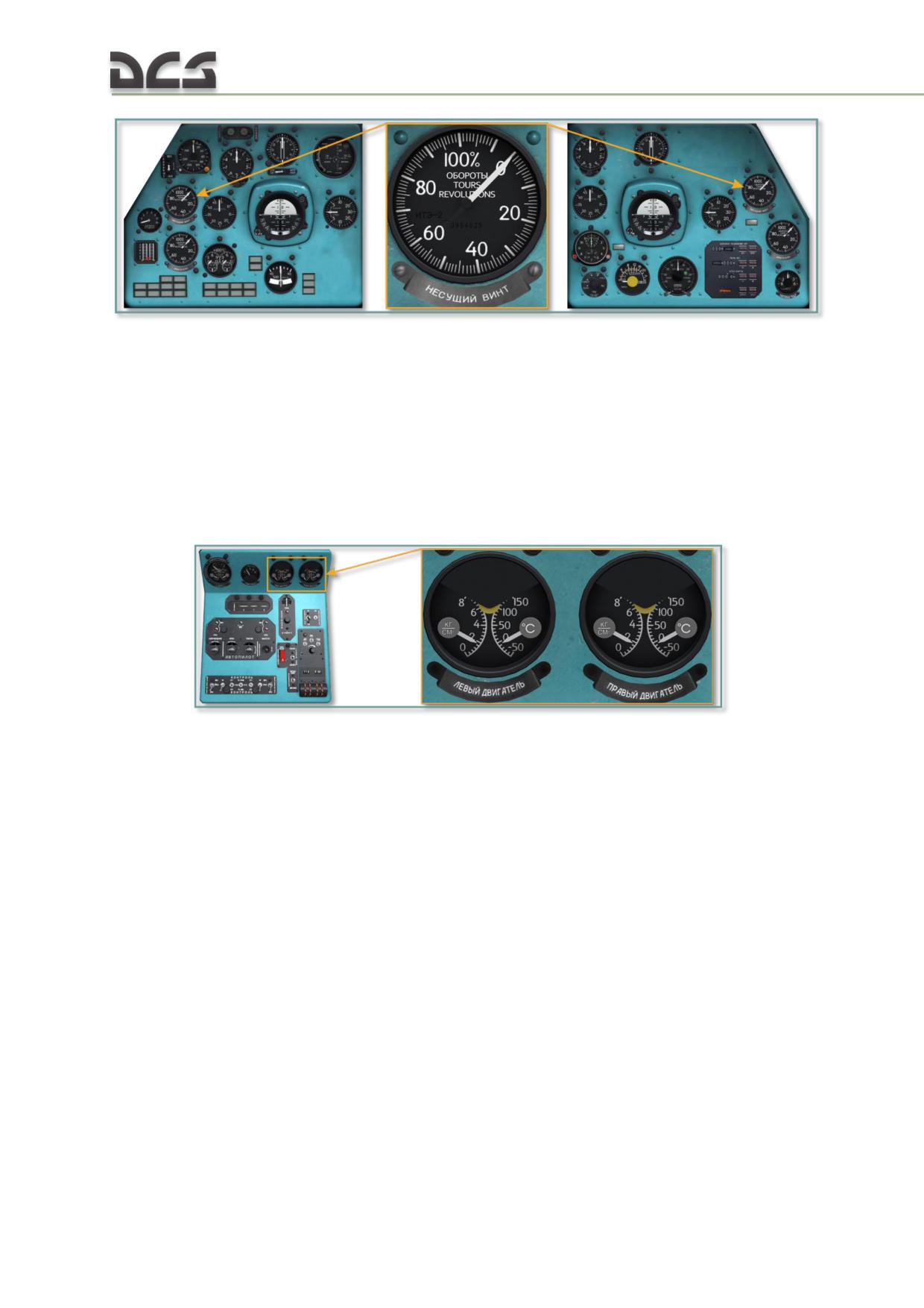
Fig. 5.21. Pilot's and copilot's main rotor tachometers
5.3.3. ЭМИ-3РИ (EMI-3RI ) Engine oil pressure/temperature gauge
The engine oil pressure/temperature gauges, one for each engine, are mounted on
the center console.
The gauge has three scales. The upper scale is not used. The lower left scale
displays the oil pressure on a scale of 0 to 8 kg/cm2. The lower right scale displays
the oil temperature in degrees centigrade on a scale of -70°C to +150°C.
Fig. 5.22. Oil pressure/temperature gauges, center console
5.3.4. ЭМИ-3РВИ (EMI-3RVI) Three pointer drive system oil
pressure/temperature gauge
The drive system oil pressure and temperature gauge is installed on the left of the
upper section of the center console. The gauge has three scales. The upper scale
displays the oil pressure in the main transmission in kg/cm2. The lower left scale
displays the oil temperature in the intermediate gearbox while the lower right scale
displays the oil temperature in the tail rotor gearbox.
86
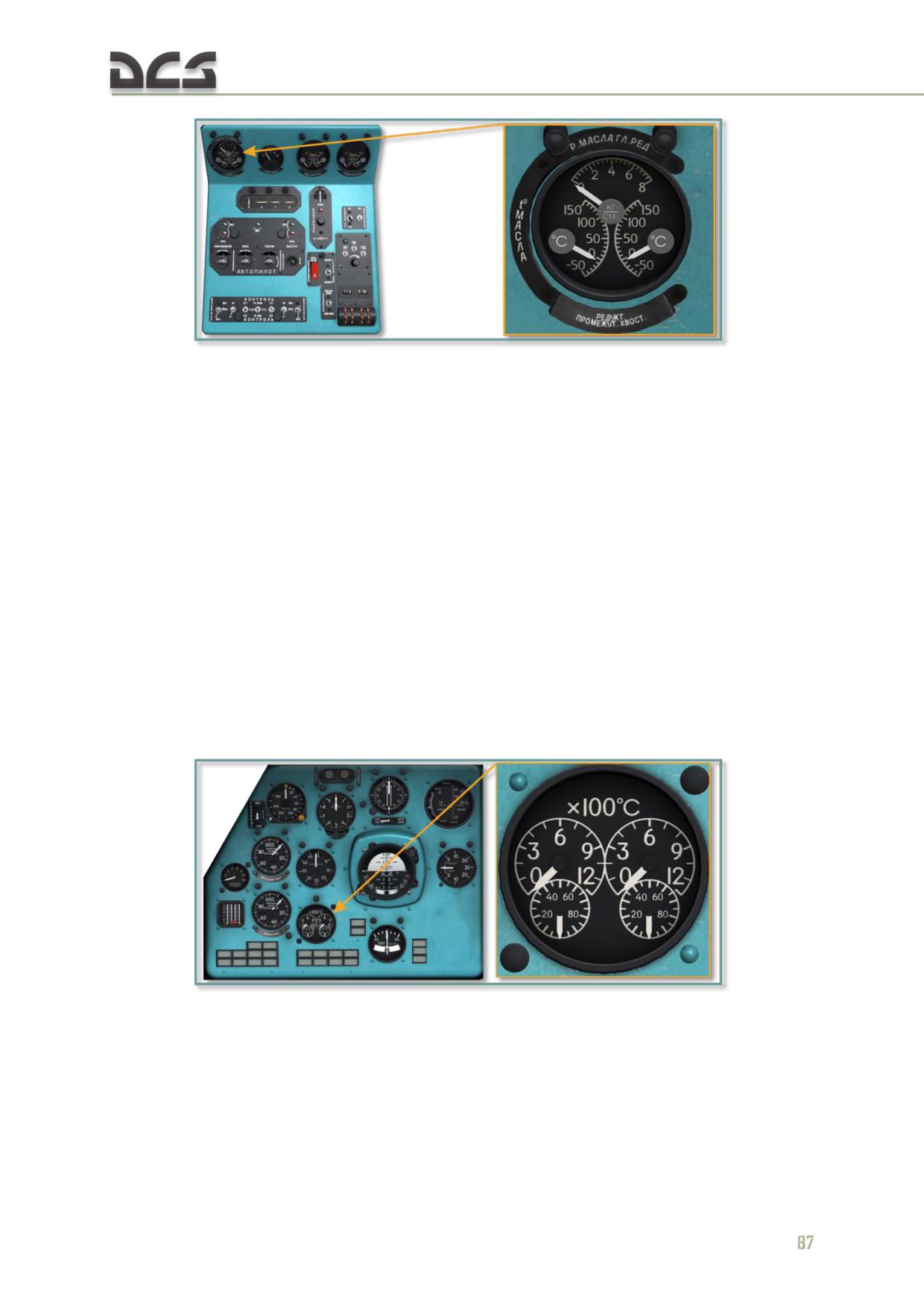
Fig. 5.23. Three pointer drive system oil pressure/temperature gauge, center console
The gauges receive temperature indications from oil temperature probes installed the
transmission gearboxes. Pressure indications are provided by a pressure transducer
in the transmission oil system.
All temperature indications are in degrees centigrade. The pressure scale displays the
oil pressure on a scale of 0 to 8 kg/cm2, graduated to 0.5 kg/cm2. The temperature
scale displays the oil temperature in degrees centigrade on a scale of -70°C to
+150°C, graduated to 10°C.
5.3.5. 2УТ-6К (2UT-6K) Power turbine inlet temperature (PTIT) gauge
The power turbine inlet temperature (PTIT) gauge is located in the lower center area
of the pilot’s instrument panel. The indicator receives temperature indications from
the thermocouple probes mounted on the engine power turbine housings. The gauge
has two scales for each engine. The large scales read in hundreds of degrees; the
small scales read in 5 degree increments. The temperature indications are in degrees
centigrade.
Fig. 5.24. PTIT gauge
The HOT ("ВОЗДУХ") and COLD ("ЗЕМЛЯ") test buttons, located on the pilot’s left
console, are used to confirm proper operation of the gauge. With the engines shut
down, the needles should move toward 960° when the COLD button is pressed. The
needles should return to zero when the COLD button is released. With the engines
running, the needles should move toward zero when the HOT button is pressed and
return to the actual PTIT readings when it is released.
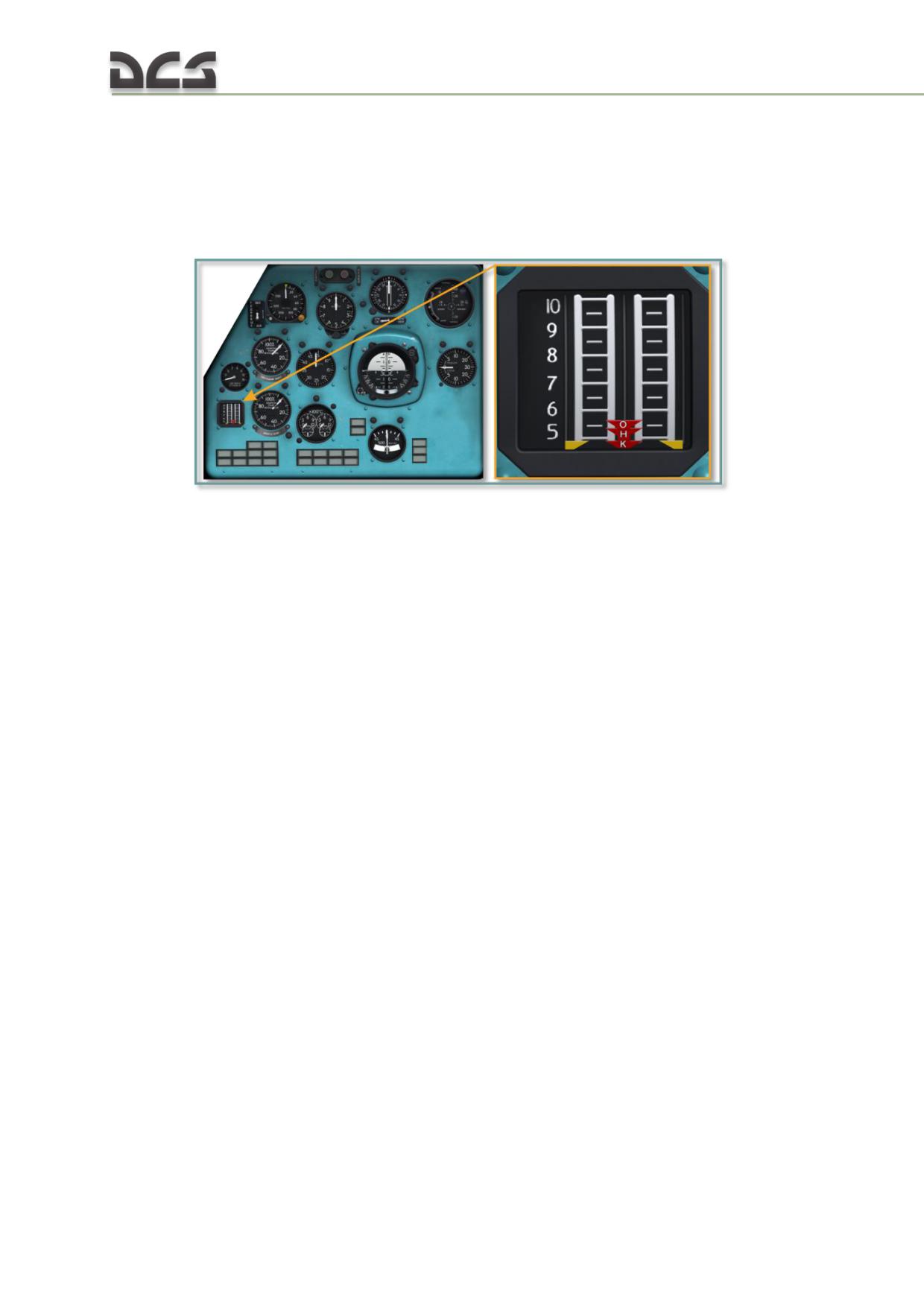
5.3.6. ИР-117 (IR-117) Engine pressure ratio (EPR) indicator
The engine pressure ratio indicator is located in the lower left area of the pilot’s
instrument panel. It is used to monitor the engine power settings. The indicator
displays current engine compressor delivery pressure in reference to takeoff,
nominal, and cruise power settings under current ambient atmosphere conditions.
Fig. 5.25. Engine pressure ratio (EPR) indicator
The indicator is connected to a pair of pressure tubes, an altitude sensor, and an
outside air temperature probe. The power setting is determined by comparing the
compressor delivery pressure pointers on the side indices (one for each engine - LH
and RH) with the power setting pointers displayed in the center scale. The position of
the power pointers in the center scale is proportional to the atmospheric pressure
and ambient temperature. The center pointer marks "O", "H", and "K" correspond to
takeoff, nominal, and cruise power settings, respectively. The indicator is scaled from
5 to 10 atmospheres.
The EPR indicates total power demand response to throttle, ECL, and collective input.
Actual power output is determined by the alignment of the two outer markers with
the center index, marked "O", "H", and "K".
The EPR indicator is used to monitor engine power settings in ambient air
temperatures of up to +24°C. Above this temperature, the dual engine tachometer is
used as the engine power settings indicator.
The reading error is ±1.5%, measured pressure range is 4.6 - 8.5 atmospheres,
effective operational altitude range is 0.5 - 2.5 km.
88
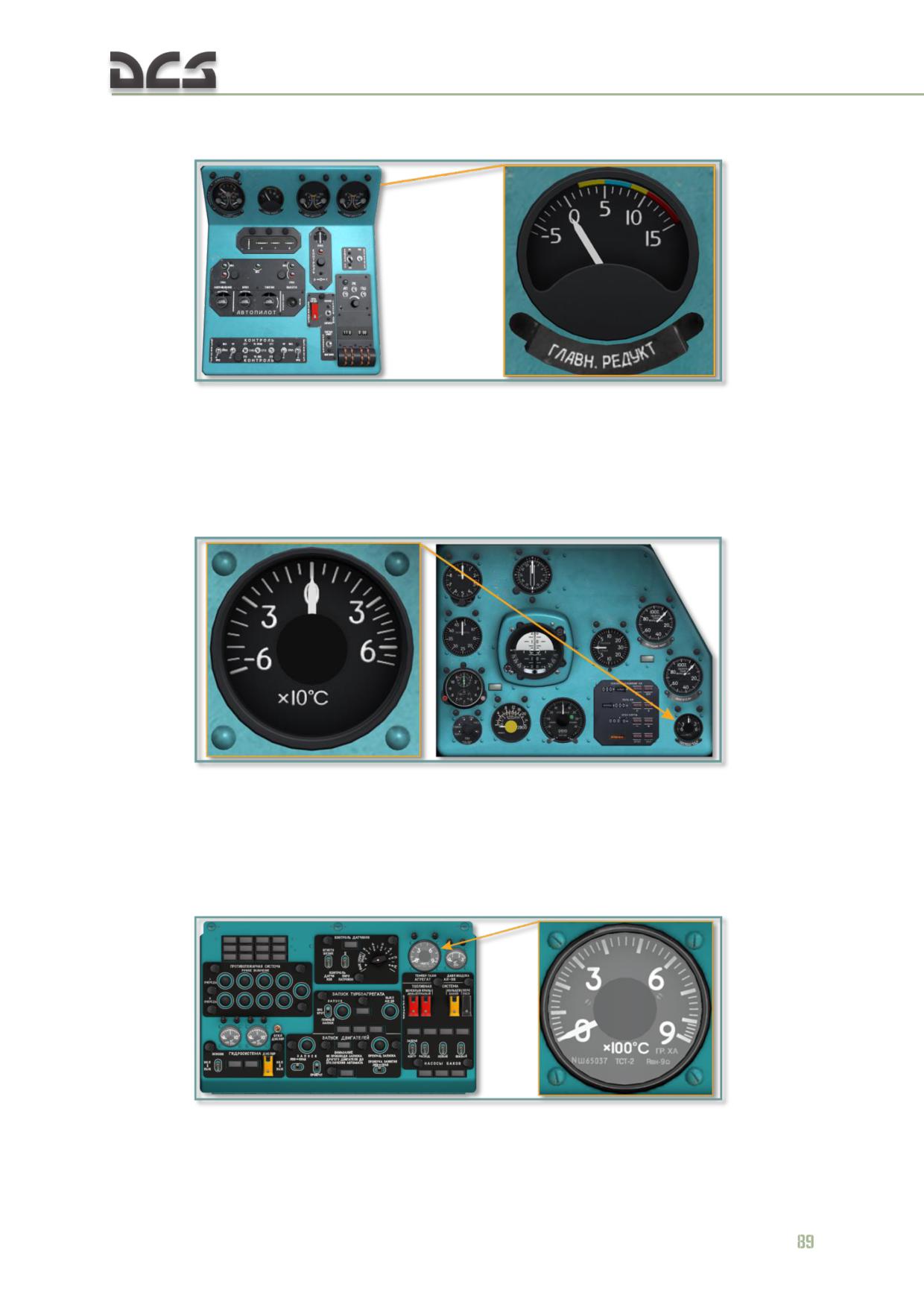
5.3.7. ТУЭ-48 (TUE-48) Main transmission oil temperature gauge
Fig. 5.26. Main transmission oil temp gauge, center console
The main transmission oil temperature gauge displays the oil temperature in degrees
centigrade. The gauge is scaled from -50°C to +150°C, graduated to 10°C.
5.3.8. ТВ-19 (TV-19) Cargo cabin temperature gauge
Fig. 5.27. Cargo cabin temp gauge (TODO: New left picture)
The cargo cabin temperature gauge displays the cargo compartment temperature in
degrees centigrade. The gauge is scaled from -60°C to +70°C, graduated to 5°C.
5.3.9. ТСТ-2 (TST-2) APU exhaust gas temperature (EGT) gauge
Fig. 5.28. APU EGT gauge, center overhead console
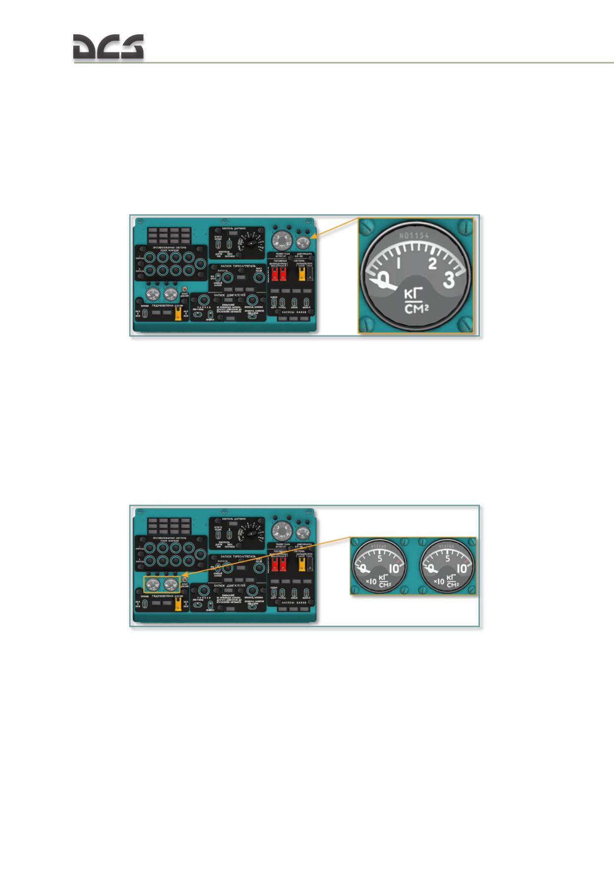
The APU exhaust gas temperature gauge is located in the upper right corner of the
center overhead console, to the left of the APU air pressure gauge. The gauge reads
in degrees centigrade. Gauge readings must be multiplied by 100 to obtain the
correct temperature. The gauge is scaled from 0 to 900°C, graduated to 20°C.
During APU start, the EGT should not exceed 880°C. Normal EGT readings should be
between 720 and 750°C.
5.3.10. УИ1-3 (UI1-3) APU air pressure gauge
Fig. 5.29. APU air pressure gauge, center overhead console
The APU air pressure gauge is located in the upper corner of the center overhead
console, to the right of the APU EGT gauge. The gauge displays the pressure in the
main bleed air channel of the AI-9V APU feeding the SV-78B air starters of the TV3-
117VM engines.
The gauge reads in kg/cm2. The gauge is scaled 0 to 3 kg/cm2, graduated to 0.2
kg/cm2.
5.3.11. УИ1-100 (UI1-100) Hydraulic pressure gauges
Fig. 5.30. Hydraulic pressure gauges, center overhead console
The MAIN and BACKUP system hydraulic pressure gauges are located in the lower
left area of the center overhead console. The gauges display the system pressure in
kg/cm2. Scale indications must be multiplied by 10 to obtain the correct pressure
reading. The gauges are scaled 0 to 100 kg/cm2 graduated to 10 kg/cm2. Normal
readings should be in the range of 45 to 68 kg/cm2.
90
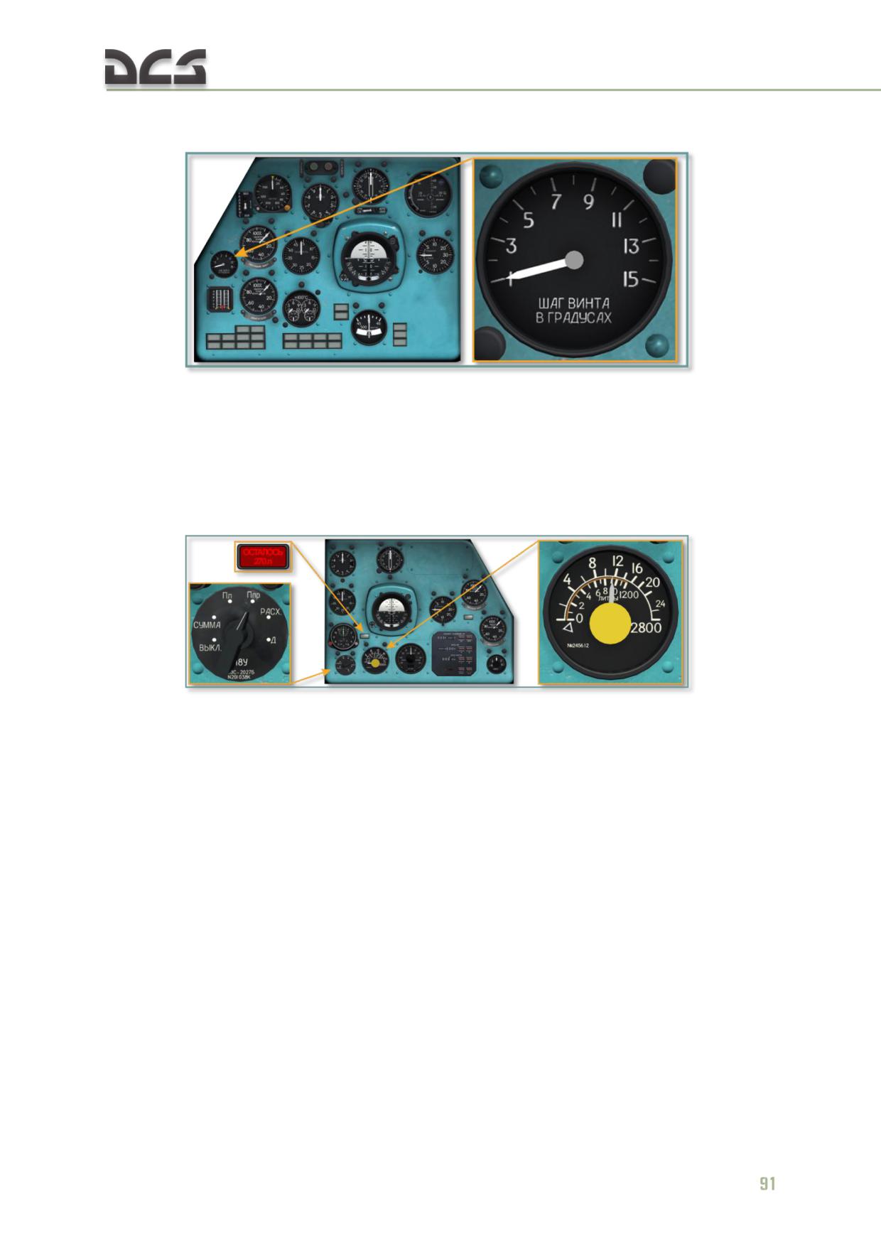
5.3.12. УП-21-15 (UP-21-15) Rotor pitch indicator
Fig. 5.31. Rotor pitch indicator
The rotor pitch indicator is used to display the collective pitch of the main rotor in
degrees. It is located on the left side of the pilot's instrument panel. The indicator is
scaled 1° to 15°, graduated to 1°.
5.3.13. СКЭС-2027В (CKES-2027B) Fuel quantity gauge
Fig. 5.32. Fuel quantity gauge
The fuel quantity gauge and selector are located in the lower left corner of the
copilot’s instrument panel. The gauge continuously indicates the quantity of fuel in
the selected tank in liters. The fuel gauge is connected to the fuel sensors installed in
the individual fuel cells. The gauge has two indicator scales. The outer scale displays
the total quantity of fuel in all tanks. The inner scale shows the fuel quantity in the
selected tank. The selector position controls the active scale. The selector positions,
from left to right, include "ВЫК" (OFF), "СУММА" (TOTAL), "Пл" (LEFT MAIN), "Ппр"
(RIGHT MAIN), "РАСХ" (SVC CELL), "Д" (LEFT AUX - not modeled in DCS: Mi-
8MTV2) positions. The scale indications must be multiplied by 100 liters to obtain the
correct quantity of fuel.
The "ОСТАЛОСЬ 270л" (270 L FUEL) warning light is located on the copilot’s
instrument panel, above the fuel gauge. The low level transmitter activates when
there are approximately 270 liters of fuel remaining in the SVC cell.
5.3.14. ИВ-500Е (IV-500E) Engine vibration monitor
The engine vibration monitor activates the caution and warning lights on the pilot’s
master caution panel if the vibration increases significantly or reaches a critical level.
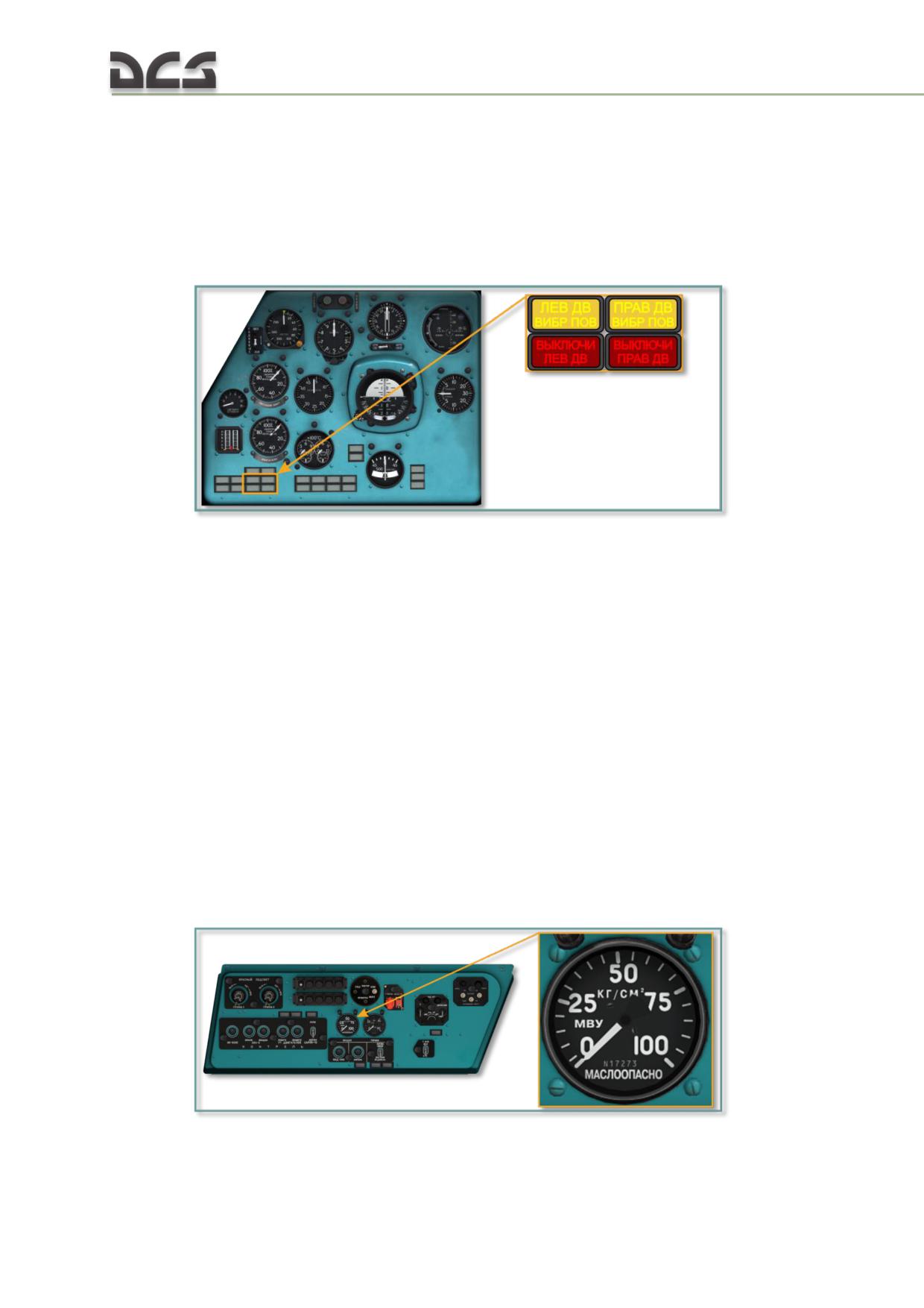
If the level of vibration reaches 45 mm/s (1.8 in/s), the system illuminates the yellow
caution light labeled "ЛЕВ (ПРАВ) ДВ ВИБР ПОВ" (LEFT (RIGHT) ENG HIGH VIBE).
It also sends a signal to the audio warning system which transmits an audio warning
over the helicopter intercom system. If the level of vibration reaches 60 mm/s (2.4
in/s), it illuminates the red warning light labeled "ВЫКЛЮЧИ ЛЕВ (ПРАВ) ДВ" (SHUT
OFF LEFT (RIGHT) ENG) and sends a signal to be recorded by the flight parameter
recorder.
Fig. 5.33. Engine vibration monitor annunciators
The vibration monitor system includes a built-in test circuit. When the "КОНТРОЛЬ
ИВ-500Е" (ENGINE VIBE TEST) button on the pilot’s left side console is pressed, all
four caution/warning lights must illuminate.
If the "ВЫКЛЮЧИ ЛЕВ (ПРАВ) ДВ" (SHUT OFF LEFT (RIGHT) ENG) light illuminates,
attempt to reduce vibration by lowering the engine power settings. If the warning
extinguishes, maintain 130-140 km/h and proceed to the nearest airfield.
If the warning persists, the faulty engine must be shut down. Flashing of both yellow
and red annunciators is permissible in a power-on glide.
IV-500E technical specifications:
monitored frequency range: 190 - 340 Hz
monitored vibration speed range: 5 - 100 mm/s
continuous operating duration: 10 h.
5.3.15. МВУ-100К (MVU-100K) Pneumatic system pressure gauge
Fig. 5.34. Pneumatic system pressure gauge, left side panel
92
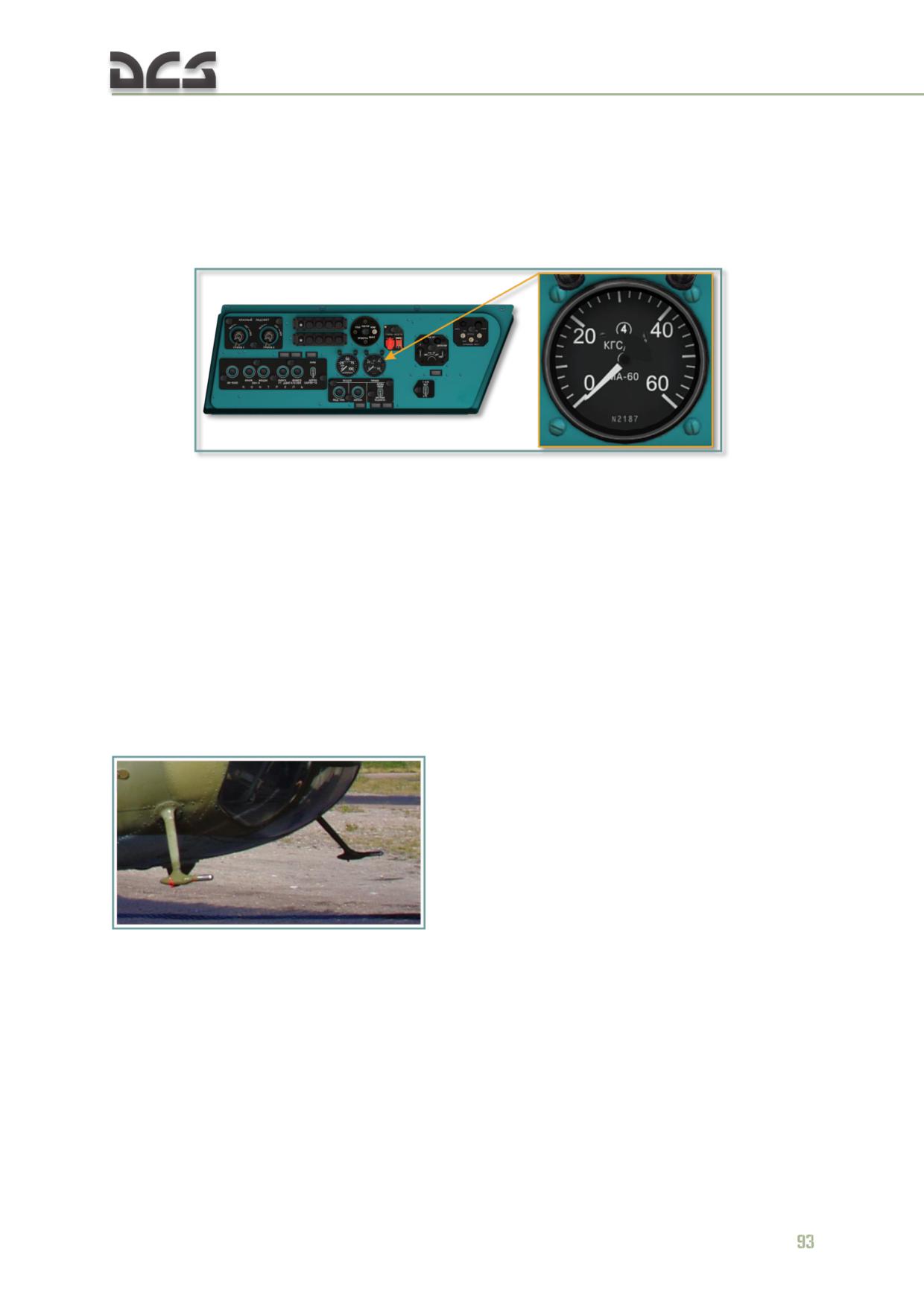
The pneumatic system pressure gauge is located on the left side console next to the
brake pressure gauge. The gauge displays pressure in the pneumatic system in
kg/cm2. Normal reading is 40-50 kg/cm2. The gauge is scaled 0 to 100 kg/cm2,
graduated to 5 kg/cm2.
5.3.16. МА-6К (MA-6K) Brake pressure gauge
Fig. 5.35. Brake pressure gauge, left side panel
The brake pressure gauge is located on the left side console next to the pneumatic
system pressure gauge. The gauge displays pressure in the main brake line in
kg/cm2. Normal reading is 30-36 kg/cm2 when the brakes are applied.
The gauge is scaled 0 to 60 kg/cm2, graduated to 2 kg/cm2.
5.4. Flight data and Navigation Systems controls and indicators
Flight data and navigation equipment includes flight instruments and related gauges,
clock, and the AP-34B autopilot (described in chapter 7.11).
5.4.1. Pitot static system
Two ПВД-6М (PVD-6M) pitot tubes are
installed on the left and right side of the
fuselage nose. The pitot tubes supply
both dynamic (impact) pressure of the
incidental airflow and static (ambient)
air pressure. Static pressure is provided
via a series of eight static pressure ports
spaced around the aft circumference of
Fig. 5.1. Left and right pitot tubes
the pitot tubes. To increase reliability,
the static ports are connected to the
instruments through a 3-position switch. The pitot tubes are equipped with electrical
heaters to protect them from freezing.
Static port switching valve. The static port switching valve allows the pilot to
select a specific port or both ports as the source of static pressure for the
instruments. The static port switching valve is mounted at the lower left corner of
the pilot’s instrument panel. With the lever set to the "О" (BOTH) (middle) position,
static pressure from the left and right ports is combined by the valve and supplied to
all of the connected instruments. When the lever is placed in the "Л" (LEFT) or "П"
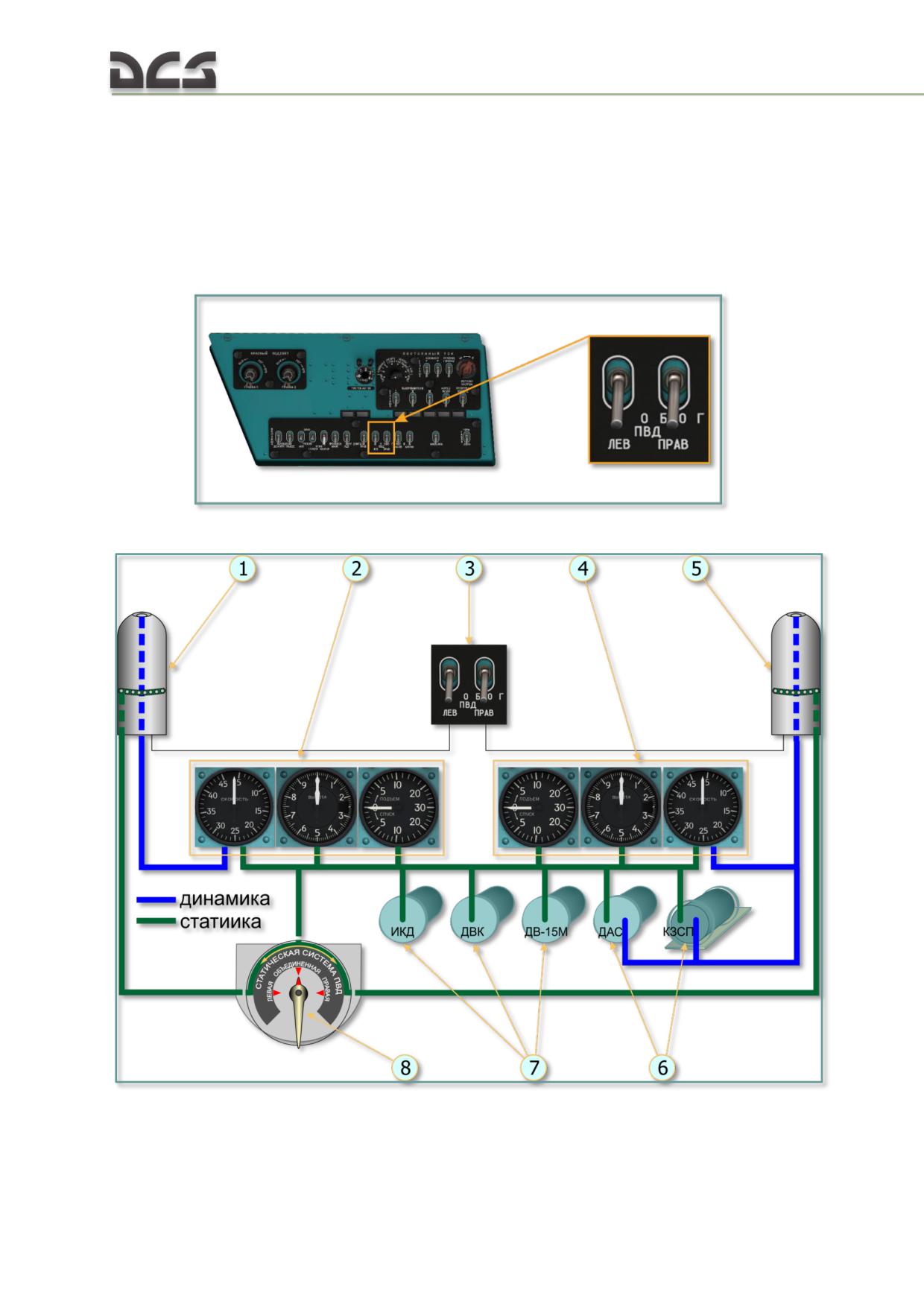
(RIGHT) position, static pressure is supplied only from the left or right port,
respectively. The left pitot tube supplies only the left (pilot's) airspeed indicator. The
right pitot tube supplies the right (copilot's) airspeed indicator and the ДАС (DAS)
airspeed sensor and КЗСП (KZSP) airspeed correction unit.
The pitot tubes are equipped with heaters to prevent obstruction of the inlets by ice.
The heaters are controlled by the "ОБОГРЕВ ПВД ЛЕВ (ПРАВ)" (LEFT (RIGHT)
PITOT HEAT) switches on the copilot's right side console.
Fig. 5.36. Pitot tube heat switches, right side panel
Fig. 5.37. Pitot static system diagram
1. Left pitot tube
5. Right pitot tube
2. Pilot's airspeed indicator, pressure altimeter,
6. Pressure data consumers
94
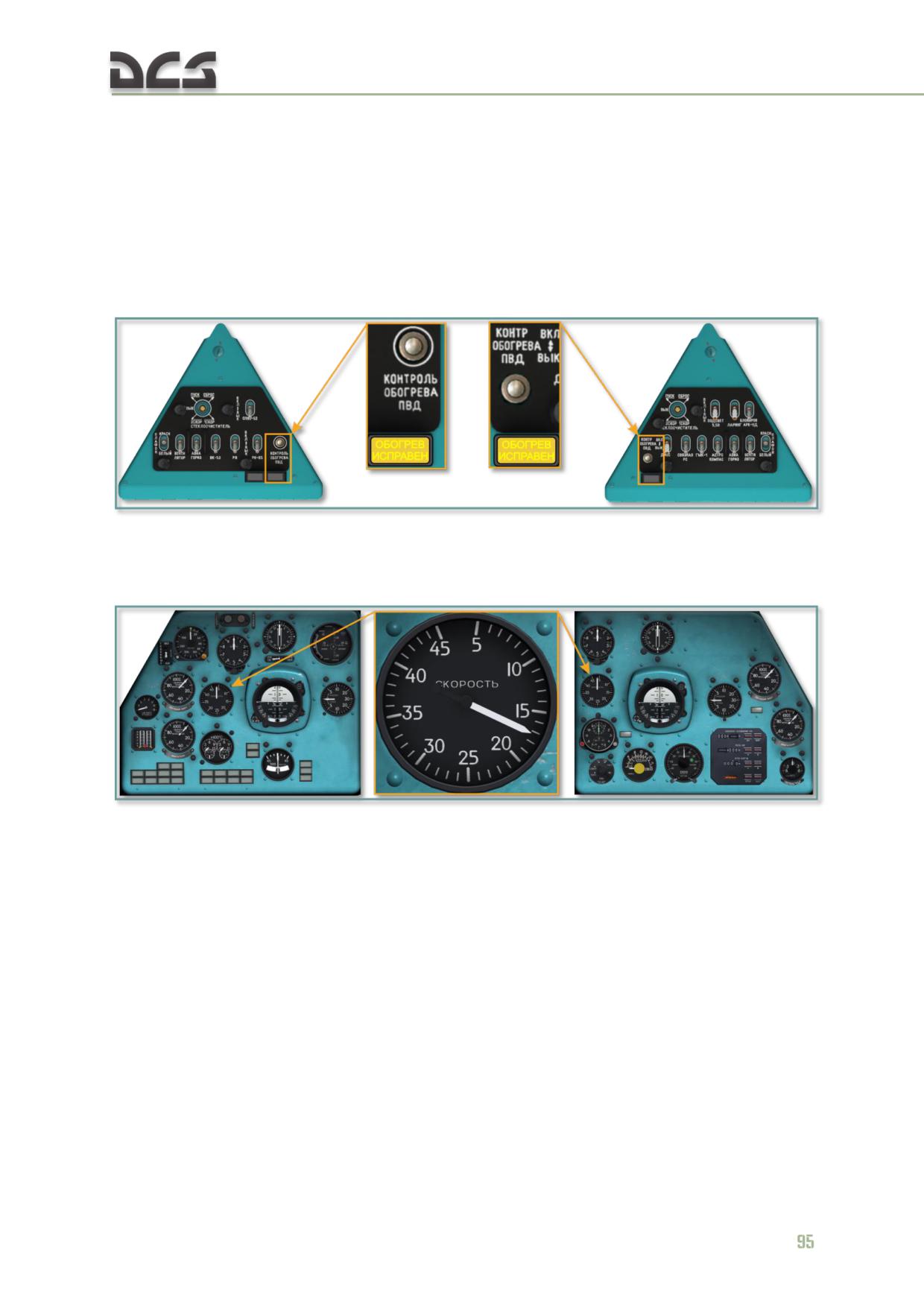
and vertical velocity indicator
7. Pressure data consumers
3. Pitot tube heat switches
8. Static port switching valve.
4. Copilot's airspeed indicator, pressure altimeter,
and vertical velocity indicator
The pitot heaters have a built-in test circuit consisting of a "КОНТРОЛЬ ОБОГРЕВА
ПВД" (PITOT HEATER TEST) button, a "ОБОГРЕВ ИСПРАВЕН" (HEATER OK)
indicator light, and a relay and microswitch for each pitot tube. The test buttons and
lights are located on the left and right triangular panels in the cockpit.
Fig. 5.38. Pitot heat test buttons and HEATER OK annunciators
5.4.2. УС-450К (US-450K) airspeed indicator
Fig. 5.39. Airspeed indicators
Two airspeed indicators are installed on the helicopter, one on the pilot's instrument
panel and one on the copilot's instrument panel. The airspeed indicators display the
indicated airspeed in a range of 0 to 450 km/h on a scale graduated to 10 km/h.
5.4.3. ВД-10К (VD-10K) pressure altimeter
Two pressure altimeters are installed on the helicopter, one on the pilot's instrument
panel and one on the copilot's instrument panel. The pressure altimeters display
barometric altitude. The indicators utilize two arrows: the large arrow displays
altitude in meters, the small arrow in thousands of meters (kilometers). The indicator
reading range is 0 to 10,000 m. The scale is graduated to 10 m for the large arrow
and 100 m for the small arrow.
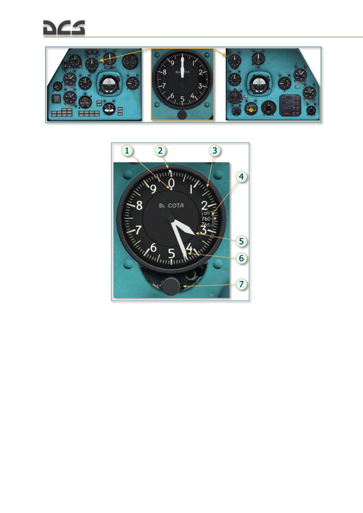
Fig. 5.40. Pressure altimeters
Fig. 5.41. Pressure altimeter function elements
1. Triangular index thousand meters
5. Arrow thousand meters
2. Triangular index hundred meters
6. Arrow hundred meters
3. The scale of the altimeter
7. Adjustment knob
4. The scale of pressure (mm Hg)
The pressure altimeter adjustment knob is used to set the arrows to 0 altitude and
adjust the reference barometric pressure. Turning the knob also moves the two
triangular indexes around the altitude scale, one around the outside scale and one
around the inside scale. The indexes are used to set the altitude difference for a
landing point located at a higher elevation than the takeoff airfield in case the actual
pressure at the landing field is unknown. Fig. 5.42 shows an example, the setting
helipad altitude 3.400m using ajustment knob (triangular indices (1) and (2) set on
3400 m altitude). The arrows indicates the barometric altitude regarding this helipad
(50 m).
96
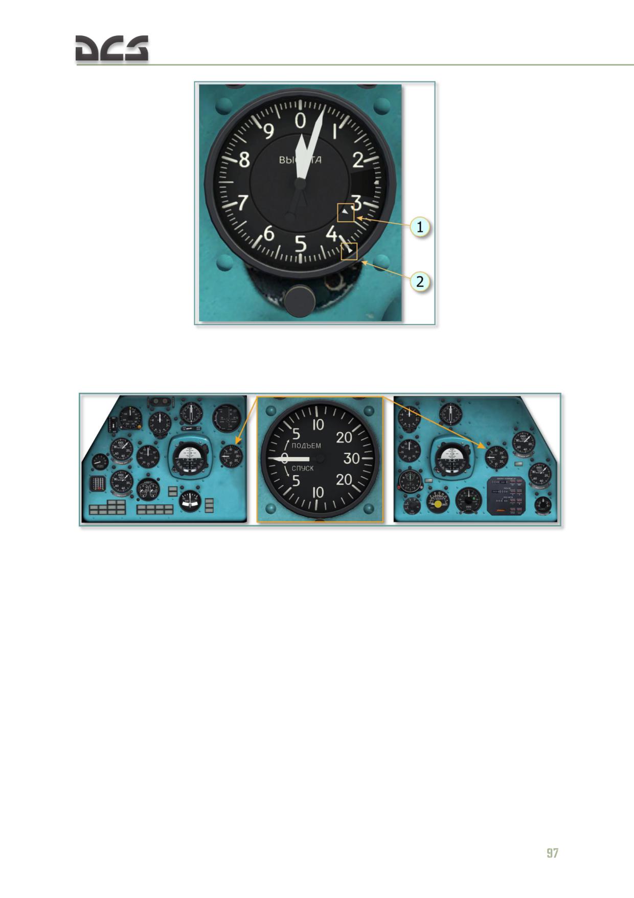
Fig. 5.42. Setting helipad altitude using ajustment knob
5.4.4. ВР-30МК (VR-30MK) vertical speed indicator (VSI)
Fig. 5.43. Vertical speed indicator (VSI)
The vertical speed indicator (VSI) is mounted in the pilot’s instrument panel. It
displays the helicopter’s rate of ascent/descent in a range of ±30 meters per second
(m/s) on a scale graduated to 1 m/s. The indicator is actuated by the rate of
atmospheric pressure change. It is connected to the static pressure system.
5.4.5. АГБ-3К (AGB-3K) attitude indicator
Attitude indicators are installed on both the pilot's and copilot's instrument panels.
The indicators display the attitude of the helicopter (roll and pitch angles) relative to
the horizon and sideslip.
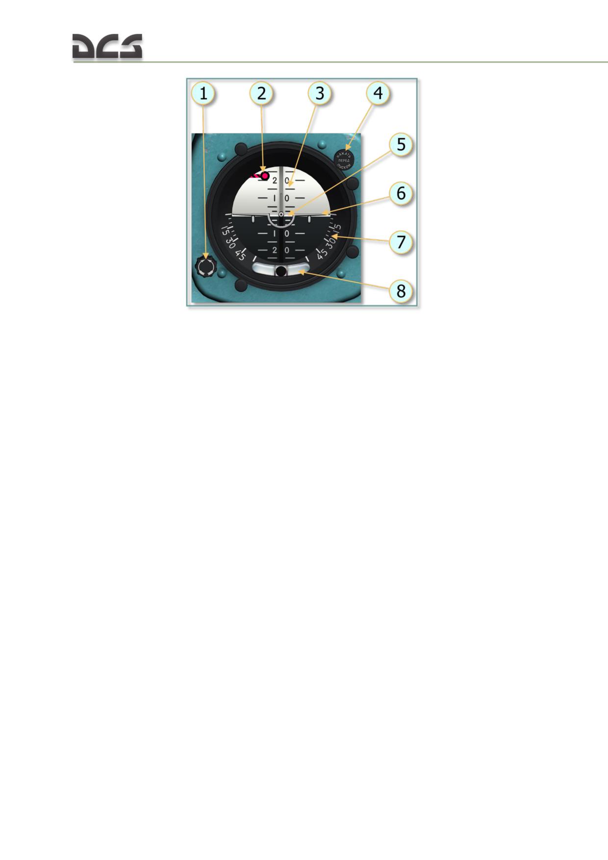
Fig. 5.44. AGB-3K attitude indicator
1. Horizon elevation adjustment knob;
5. Horizon line;
2. Warning flag;
6. Aircraft symbol;
3. Pitch scale;
7. Roll scale;
4. "АРРЕТИР" (CAGE) button (press before start);
8. Slip indicator
The pilot's AGB-3K attitude indicator supplies pitch and roll data to the flight data
recorder and to the DISS-15D Doppler system. The copilot's attitude indicator
supplies pitch and roll data to the autopilot system.
The attitude indicators utilize a free-mounted gyroscope with a three-phase
gyromotor. Roll angles of 85-87˚ will cause the gyromotor to gimbal lock (lose one of
three degrees of freedom).
A warning flag appears at the top of the instrument face in the event of power
failure.
The gyromotor is connected to the ВК-53РШ (VK-53RSh) gyro correction cutout
switch to reduce accumulated error during prolonged unilateral acceleration
(increasing speed, braking, and banked turns).
AGB-3K attitude indicator specifications:
time to readiness, no more than:
1.5 min
error:
o up to 30° of deflection, no more than:
±1°
o over 30° of deflection, no more than:
±2°
To test the AGB-3K attitude indicator:
ensure AC and DC power is on
press the "АРРЕТИР" (CAGE) button on the indicator (all three axes of the
gyroscope are set perpendicular to each other);
98
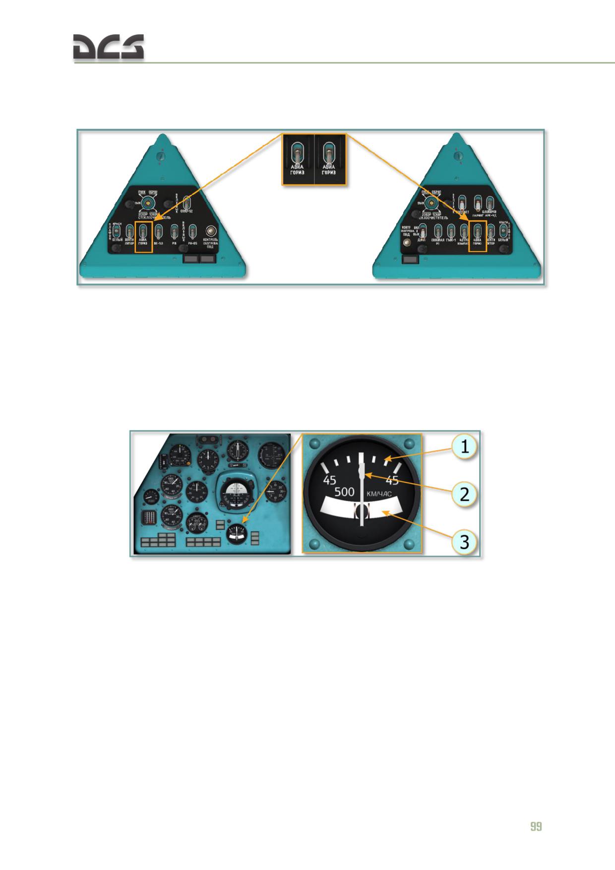
turn on the "АВИАГОРИЗОНТ" (GYRO HORIZON) switch on the left and
right triangular panels;
verify the indicator functionality (flags should stow away).
Fig. 5.45. "АВИАГОРИЗОНТ" (GYRO HORIZON) switches on the left and right triangular
panels
A failure of the copilot's (right) attitude indicator will result in the failure of the АПБ-
34Б (APB-34B) autopilot system. Use the pilot's (left) attitude indicator to continue
the flight. The autopilot system is not designed to interact with the pilot's attitude
indicator.
5.4.6. ЭУП-53 (EUP-53) Turn and Slip indicator
Fig. 5.46. Turn and slip indicator
1. Display scale
3. Slip ball
2. Rate of turn needle
The turn and slip indicator is mounted on the pilot’s instrument panel. The
instrument scale displays in degrees with a range of ±45° in 15° increments.
The indicator displays the helicopter's angular velocity around the vertical axis. Below
the center of the indicator is a slip ball tube.
When performing properly balanced (coordinated) turns, the rate of turn needle
indicates current bank angle.
The indicator utilizes rate gyros. It is powered with 27 VDC via the "УКАЗАТЕЛЬ
ПОВОРОТА" (TURN IND) circuit breaker on the right circuit breaker panel.
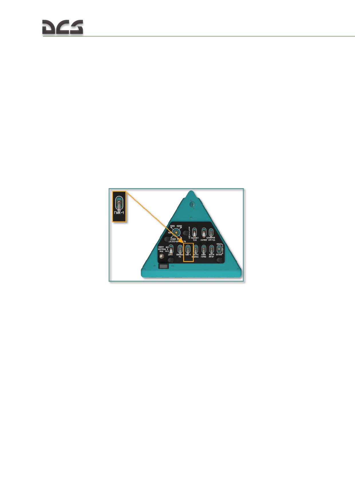
One must take into account that while performing coordinated turns, readings of the
EUP-53 turn and slip indicator are not corresponding to actual roll angles. Thus,
while turning at a speed of 160-200 km/h with roll angle of 5, 10 or 15°, readings of
the turn and slip indicator will be 15-10, 30-25 or 45-35° correspondingly. Note, that
due to high sensitivity of this indicator, it’s needle will be constantly oscillating,
therefore pilot must read average value.
5.4.7. ГМК-1А (GMK-1A) gyromagnetic compass set
The GMK-1A gyromagnetic compass set is a direction sensing system which provides
a visual indication of the helicopter heading, required turn angle, and magnetic or
true navigation bearing. The system consists of a number of interconnected magnetic
and gyroscopic devices. Course information is displayed on the УГР-4УК (UGR-4UK)
directional gyros installed in both the pilot and co-pilot instrument panels.
The system is turned on by setting the "ГМК-1" (COMPASS SYSTEM) switch on the
right triangular panel to the ON (up) position.
Fig. 5.47. "ГМК-1" (COMPASS SYSTEM) switch, right triangular panel
The ПУ-26 (PU-26) control panel located on the lower right corner of the right
overhead console is used to:
set the compass system operating mode ("МК" (MK, magnetic compass
mode) or "ГПК" (GPK, directional gyro mode));
input latitude correction using the "ШИРОТА" (LATITUDE) knob to correct
for apparent drift due to the Earth's rotation;
correct for mechanical drift due to friction and imperfect balancing within
the gyro;
set the assigned course on the directional gyro indicator using the "ЗК"
(3K, assigned course) selector in GPK operating mode;
perform fast alignment using the ЗК selector in MK operating mode;
monitoring and control of the system.
100
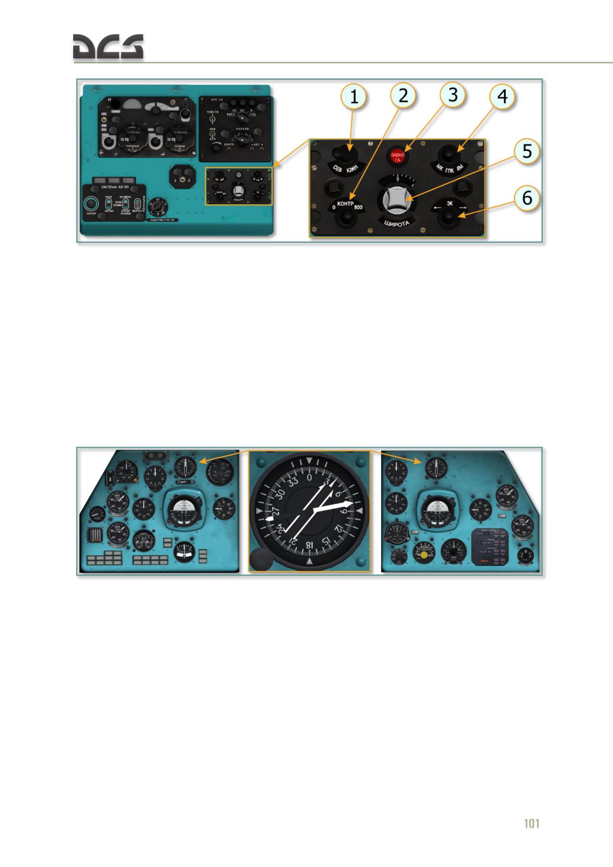
Fig. 5.48. PU-26 control panel, right overhead console
1. "СЕВ-ЮЖН" (NORTH-SOUTH) switch
4. "МК. ГПК. АМ" (MK-GPK-AK) mode selector
2. "КОНТРОЛЬ" (TEST) selector
5. "ШИРОТА" (LATITUDE) knob
3. "ЗАВАЛ ГА" (BANK CORR) light
6. "ЗК" (assigned course) select or
The УГР-4УК (UGR-4UK) directional gyro displays the helicopter heading, required
turn angles, and bearings. Two directional gyros are installed, one on the pilot's and
one on the copilot's instrument panel. The helicopter heading is indicated by a
moving compass card relative to a fixed index at the top of the compass. The
compass card is graduated to 2° and marked numerically for each 30° (divided by
10).
Magnetic heading error does not exceed ±1.5°.
Fig. 5.49. UGR-4UK directional gyro
In GPK mode, the cumulative error of the system does not exceed ±2,5° per hour.
Time to readiness in MK mode does not exceed 3 min, in GPK mode does not exceed
5 min.
Normal alignment rate in MK mode is no less than 1.5° - 7°/min. Fast alignment rate
in MK mode is no less than 6°/sec. Alignment rate using the 3K switch is no less than
2°/sec.
The system utilizes a flux detector providing automatic magnetic heading corrections
to the gyro, eliminating the need for frequent manual realignment. The system can
operate in one of two modes: MK or GPK.
GPK is the primary mode, utilizing the flux detector and a magnetic deviation
compensator to correct gyro drift. When operating in GPK mode, the gyro is the
source of heading data.
The gyro gradually accumulates error in azimuth due to the earth's rotation
(apparent drift) as well as mechanical friction and imbalances within the device
(mechanical drift). The latitude corrector is used to correct these errors.
To select GPK mode, set the mode selector to the "ГПК" (GPK) position on the PU-26
control panel.
MK mode is used to align the gyro to the signal provided by the flux detector and
magnetic deviation compensator. To select MK mode, set the mode selector to the
MK position on the PU-26 control panel.
The system is initialized in MK mode to allow the unit to establish baseline heading
data.
The gyro can be aligned at normal speed (via the ЗК switch on the control panel) or
fast speed.
Automatic fast alignment occurs whenever the operating mode is switched from GPK
to MK.
Heading indication accuracy is checked periodically using the TEST switch. The
switch is toggled to the 0° and 300° positions, the resulting indication cannot vary by
more than +/- 10°. Testing the system must also illuminate the "ЗАВАЛ ГА" (BANK
CORR) warning light.
Preparing the compass set for operation:
set the "СЕВ-ЮЖН" (NORTH-SOUTH) selector to correspond to current
hemisphere;
set current latitude using the "ШИРОТА" (LATITUDE) knob;
test the set using the "КОНТРОЛЬ" (TEST) switch;
align the gyro to the correct magnetic heading by pressing the 3K switch
(in MK mode) or by turning the compass card using the 3K switch until the
correct heading is set (in GPK mode);
verify proper alignment and correct magnetic heading prior to takeoff.
5.4.8. КИ-13К (KI-13K) magnetic compass
The magnetic compass is mounted on the center windshield left frame. The magnetic
compass is used to indicate the magnetic helicopter heading and acts as an
autonomous reserve heading indicator. The compass scale is graduated in 5°
increments with number markings every 30°. The cardinal points are marked with
Cyrillic characters: "C" - North, "Ю" - South, "B" - East, and "3" - West.
102
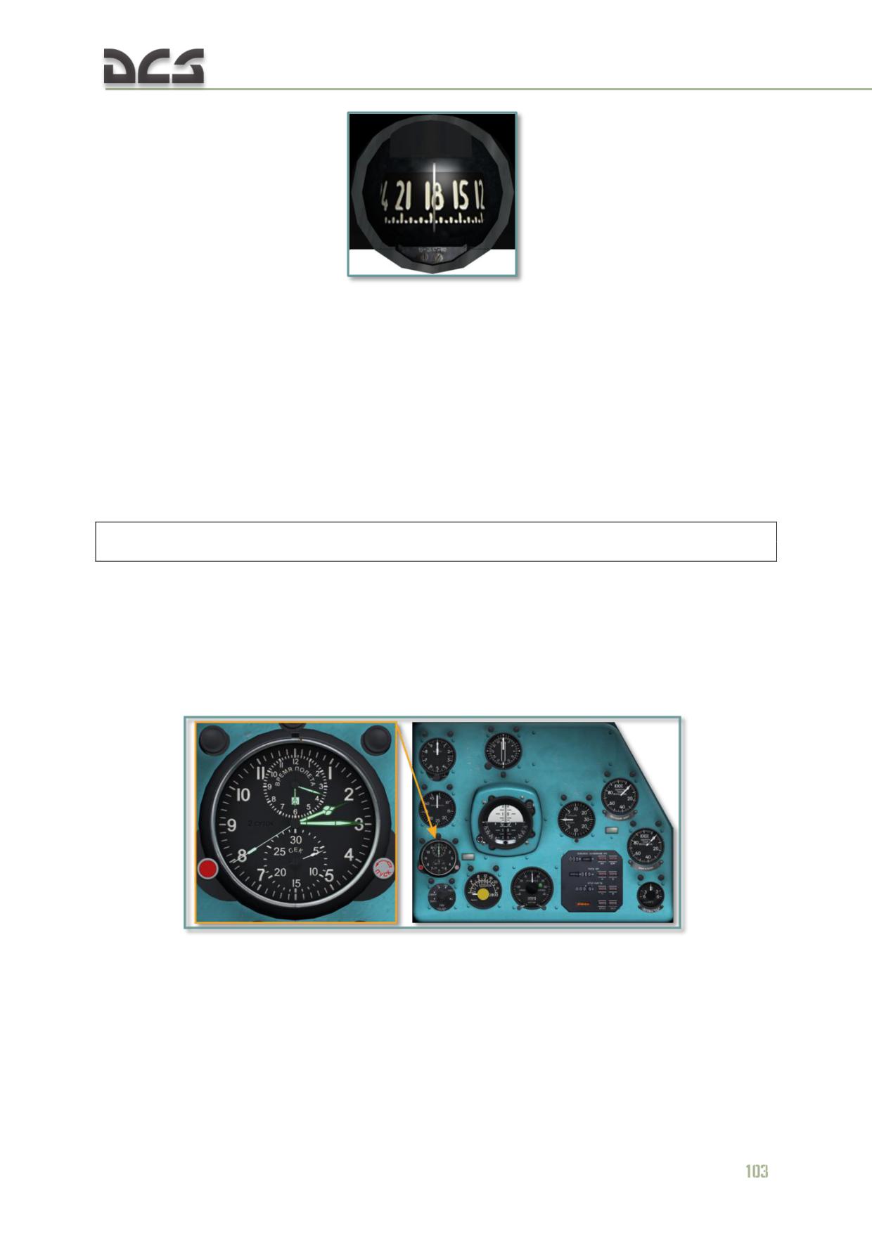
Fig. 5.50. Magnetic compass
Magnetic compass specifications:
magnetic deviation (with no deviation compensator): ±1°;
pivot friction: no more than 1°;
magnetic deviation on courses of 0°, 90°, 180°, 270°: no more than
±2.5°;
The compass period (time required to settle oscillations) in temperatures of
-60°C to +50°C is no greater than 17 seconds.
The compass is designed to function properly at roll angles of up to 17°.
Because the magnetic compass displays a compass heading, local magnetic variation as well compass
deviation must be corrected to determine required true heading.
5.4.9. АЧС-1 (AChS-1) clock
The mechanical clock Molnija AChS-1 is installed on the copilot's instrument panel.
The clock displays the current time of day in hours, minutes, and seconds. It can also
be used to measure mission/flight time in hours and minutes, and as a chronometer
to accurately measure short time periods (up to an hour) in minutes and seconds.
Fig. 5.51. Clock
The clock is equipped with electrical heating elements for cold weather operation.
The clock heater is controlled by the "ОБОГРЕВ ЧАСОВ" (CLOCK HEAT) switch on
the right side console. The heater allows clock operation at temperatures below
+5°C.
Operating in normal temperatures, the clock is accurate to ±20 sec/24 hrs.
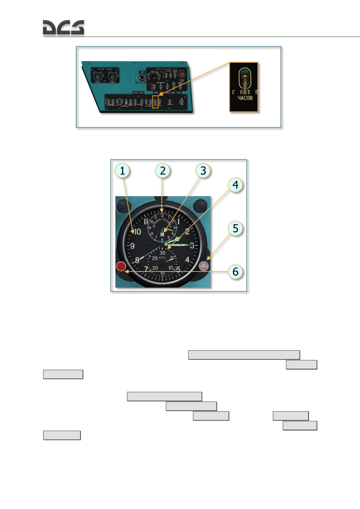
Fig. 5.52. "ОБОГРЕВ ЧАСОВ" (CLOCK HEAT) switch, right side console
Fig. 5.53. Clock functional elements
1. Outer dial and time-of-day clock hands
4. Stopwatch clock dial 5. right knob: clock /
2. 12 h mission (flight) time clock dial
stopwatch start button
3. Mode indicator window
6. Left knob.
The time of day display operates continuously. Flight (mission) time can be activated
as desired by pressing the left red knob (6)
[RALT + RCTRL + RSHIFT + C]. The
stopwatch can be activated as desired by pressing the right knob (5)
[RALT +
RSHIFT + C]
To set the time, first stop the clock by rotating the right button crown (5), labeled
ПУСК (START), clockwise
[RCTRL + RSHIFT + .] when the second hand points to 12.
Then pull the left button crown (6)
[RSHIFT + M] while holding down the right
mouse button, and rotate it counter-clockwise
[LALT + ,]
or clockwise
[LALT + .]to
set the desired time. Rotating the right button crown counter-clockwise
[RCTRL +
RSHIFT + ,]
again resumes clock operation with the new time setting.
104
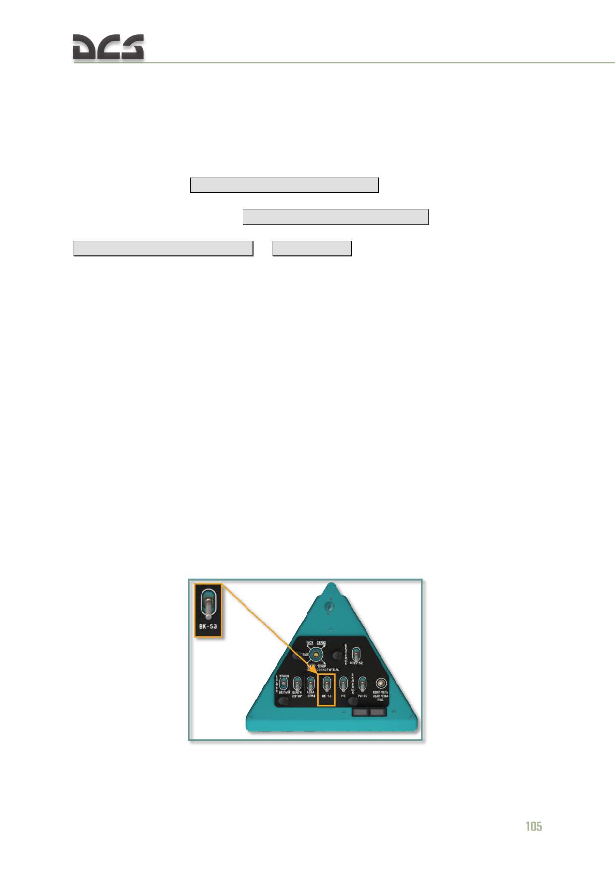
Flight (mission) time is indicated on the small scale at the top of the clock face. Flight
time mode is indicated by the following three markings inside the mode indicator
window (3):
Red: Flight time is running.
Red-white: Flight time is stopped.
White: Flight time is reset (standby).
Press the left button
[RALT + RCTRL + RSHIFT + C]
to start the timer. The mode
indicator window will show red and the timer will start ticking. To stop the timer,
press the left button (6) again
[RALT + RCTRL + RSHIFT + C]
. The mode indicator
window will show red-white. To reset the timer, press the left button once again
[RALT + RCTRL + RSHIFT + C]
or
[RSHIFT + M]
. The mode indicator will now show
white.
The stopwatch (4) is the small scale at the bottom of the clock face and is used to
accurately measure short time spans (up to 1 hour). It is controlled with the right
button (5), in a similar fashion as the mission time clock: Press the right button to
start the timer, press it again to stop the timer and press it once again to reset the
timer.
The clock spring is wound manually by rotating the left button crown counter-
clockwise to its mechanical stop. The spring contains enough energy for two days of
operation.
5.4.10. ВК-53РШ (VK-53RSh) gyro correction cutout switch
The VK-53RSh gyro correction cutout switch is designed to automatically disable
lateral gyro correction for the attitude indicator and gyro compass set gyroscopes to
reduce accumulated error during prolonged unilateral acceleration (increasing speed,
braking, and banked turns). Correction cutout occurs whenever angular velocity is
greater than 0.3°/sec. Correction cutout does not occur from abrupt and unsustained
changes in flight conditions.
The gyro correction cutout switch is turned on via the "ВК-53" (VK-53) switch on the
left triangular panel.
Fig. 5.54. "ВК-53" (VK-53) gyro correction cutout switch, left triangular panel
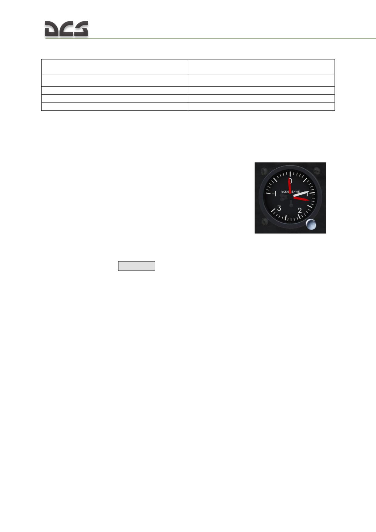
VK-53RSh specifications:
Power voltage:
36 VAC ±5% 3-phase power; 400 Hz;
27 VDC ±10%.
Correction cutout angular velocity
0.3°/sec.
Duration of correction cutout
3 - 15 sec.
Time to readiness:
no more than 1 min
Mass:
2.7 kg
5.4.11. G-load indicator
The accelerometer (or "G-meter") indicates the current maneuver loading on the
helicopter; it is measured in regards to normal gravity (1G). The red needles
indicate the highest and lowest G attained during a sortie. A button in the lower right
of the scale is used to reset the lowest and highest attained G
The scale starts at 1 G (the earth's normal gravity) and is demarcated from -1 to +3
G.
Reset needles button
[LShift + -]
106
RADIO COMMUNICATION
6
AND NAVIGATION SYSTEMS
DIGITAL COMBAT SIMULATOR Mi-8МТV2
6. RADIO COMMUNICATION AND NAVIGATION SYSTEMS
Radio communication and navigation systems of the Mi-8MTV2 include:
voice communication systems
radio navigation systems
transponder and warning systems
special purpose radio systems
Radio communication and navigation systems provide:
communication between crew members
communication with ground stations
communication between aircraft
transmission of audio warnings to crew members and ground control
stations
transmission of identification responses and emergency signals
radio homing on navigation beacons
Electrical power to the radio systems is provided via:
28.5 VDC from three ВУ-6А (VU-6A) rectifiers, each rated at 6 kW
115 VAC 400 Hz single-phase ТС/1-2 (TS/1-2) power transformer
36 VAC 400 Hz three-phase ТС 330С04Б (TS 330S04B) power transformer
Emergency power sources:
two 12САМ-28 (12SAM-28) batteries and the СТГ-3 STG-3 AC generator
ПО-500А (PO-500A) 115 VAC and ПТ-200Ц (PTs-200Ts) 36 VAC 400 Hz
inverters
All radio equipment is housed in the tail cone, radio compartment, and cockpit.
6.1. Radio communication systems
Radio communication systems installed on the Mi-8MTV2 include:
СПУ-7 (SPU-7) intercommunications set (ICS)
Р-863 (R-863) VHF/UHF command radio set (AM/FM 2-way air-to-ground
and air-to-air communication)
Ядро-1А (YaDRO-1A) HF radio set
Р-828 (R-828) LVHF radio set
П-503Б (P-503B) recording equipment (not implemented)
РИ-65 (RI-65) audio warning system
commutation and volume leveling system
6.1.1. СПУ-7 (SPU-7) intercommunications set (ICS)
The SPU-7 intercommunications set (ICS) is a signal distribution system designed to
provide internal crew communication, airwave transmission via the R-863, R-828,
YaDRO-1A radio sets, monitoring of ADF code ID signals, as well as transmission of
signals from the audio warning system and radar altimeter.
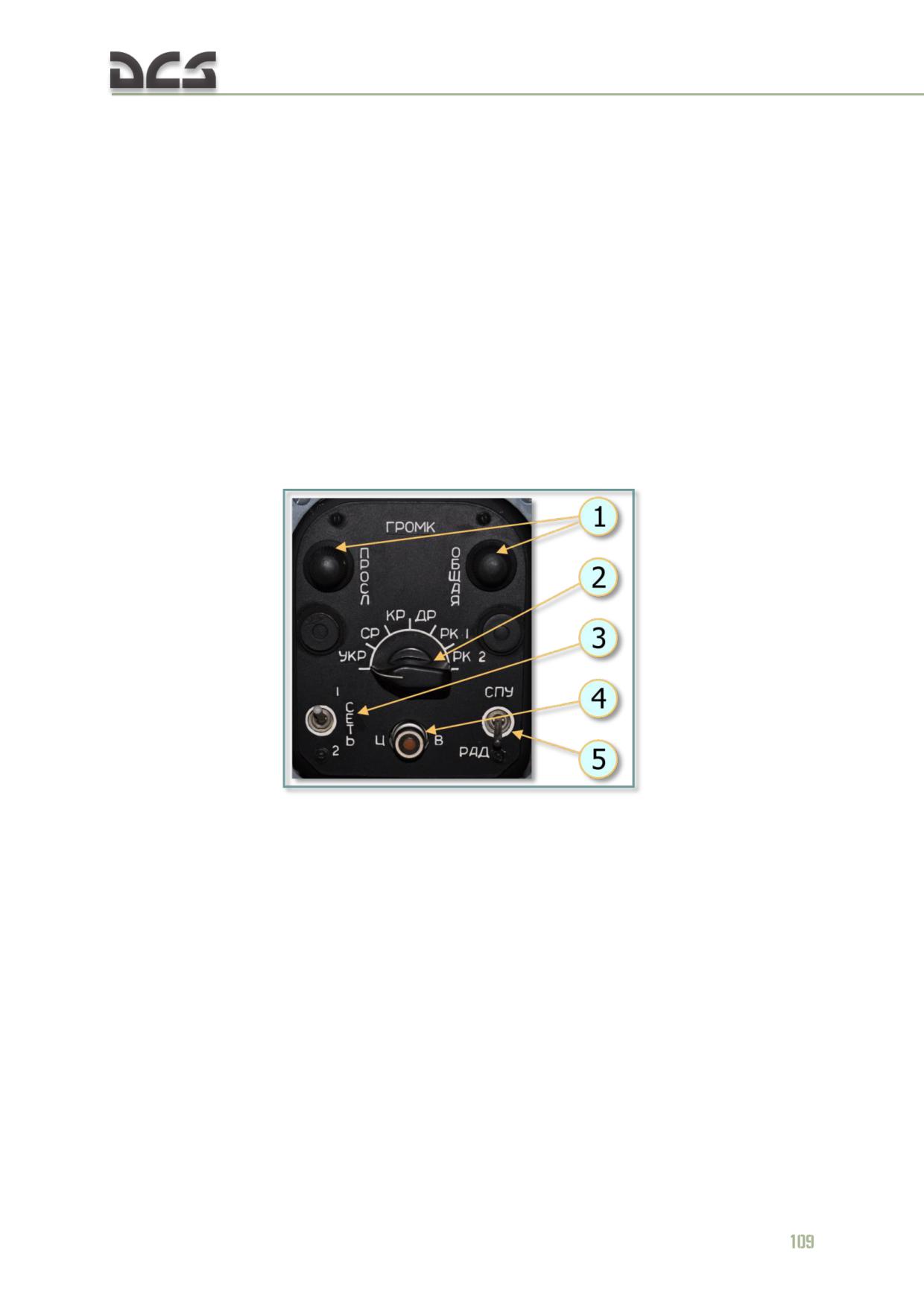
SPU-7 components:
amplifier
distribution unit
control boxes for pilot and copilot located to the left and right of the
circuit breaker consoles, respectively
control box in the troop commander station in the cargo cabin, as well as
the "ЛАРИНГ ВКЛ. - ВЫКЛ." (MIC) switch
three additional ICS tie-in points:
o crew chief station;
o winch operator station;
o tail gunner station;
"ЛАРИНГ ВКЛ.- ВЫКЛ." (MIC) switch on the right triangular panel
"СПУ - РАДИО" (ICS RADIO PTT) buttons on the pilot and copilot cyclic
control stick
"СПУ-7" (SPU-7) circuit breaker on the right circuit breaker panel
Fig. 6.1. SPU-7 control panel
1. "ОБЩАЯ" (MASTER) and "ПРОСЛ" (MONITOR)
3. "СЕТЬ 1-2" (NET 1-2) - not utilized;
volume control knobs to set volume of internal
4. "ЦВ" (ALL CALL) button for transmission of
and external comms.;
emergency messages (when pressed, interphone
2. rotary selector to select source to monitor:
signal is transmitted to all ICS stations at doubled
"УКР" (UHF) - R-863 UHF/VHF radio set
volume level, audio warning messages are
"СР" (HF) - YaDRO-1A radio set
transmitted with maximum volume level);
"КР" (VHF) - R-828 UHF radio set
5. "СПУ-РАД" (ICS-RADIO) selects
"ДР" (SW) - not utilized
communication via ICS or the selected radio
"РК 1" (ADF) - ARK-9 ADF set
"РК 2" (SAR) - ARK-UD VHF homing set
Features of the "СПУ-РАД" (ICS-RADIO) switch
When this switch is set to the СПУ (ICS) position and the unified ICS RADIO PTT
button on the pilot or copilot cyclic control stick is pressed to the first position (one click)
or second position (second click) intercom is used. When this switch is set to the РАД
(RADIO) position and the unified ICS RADIO PTT button on the pilot or copilot cyclic
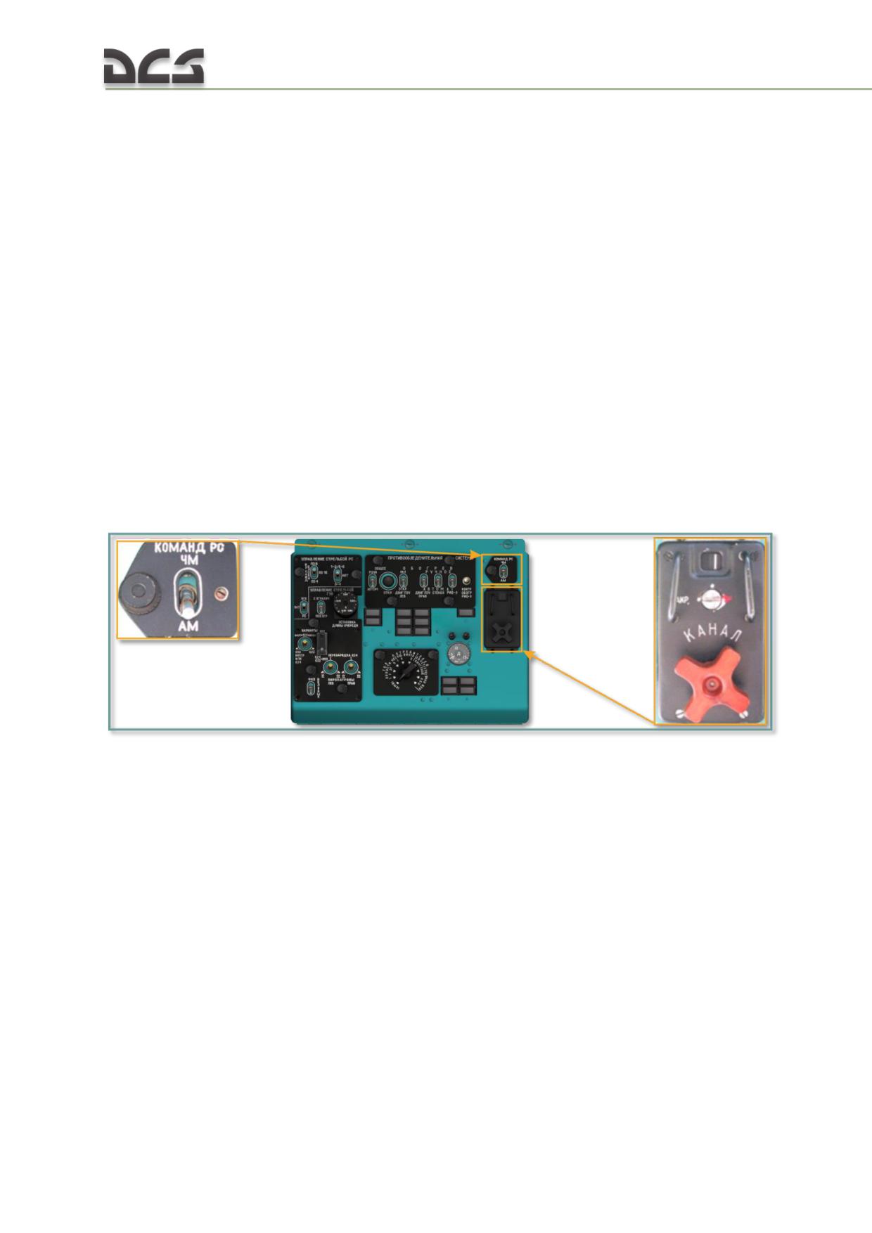
control stick is pressed to the first position (one click), then intercom is used. When
pressed to the second position (second click) - radio is used.
When in РАД (RADIO) position, broadcast transmissions are heard at a normal volume
level, while crew is heard with reduced volume. To adjust volume, pilot should use the
ОБЩАЯ (MASTER) and ПРОСЛ (MONITOR) knobs.
When the SPU-RAD switch is set to СПУ (ICS) position, intercom volume is controlled by
the ОБЩАЯ (MASTER) knob and radio volume by the ПРОСЛ (MONITOR) knob.
When the SPU-RAD switch is set to РАД (RADIO) position, intercom volume is controlled by the
ПРОСЛ (MONITOR) knob and radio volume by the ОБЩАЯ (MASTER) knob.
6.1.2. Р-863 (R-863) VHF/UHF command radio set
The R-863 radio set provides two-way voice communications in the VHF range of 100
to 149.975 MHz and UHF range of 220 to 399.975 MHz in AM or FM modes. Minimum
frequency separation between adjacent channels is 25 kHz. Frequency stabilization is
achieved by means of a digital synthesizer which provides instant selection of 20
fixed frequencies that are preset on the ground (R-863 channel selector panel) or
manual frequency control (R-863 frequency control unit). An emergency receiver
built into the radio set provides standby reception of one preset emergency
frequency (121.5 MHz or 243 MHz).
Fig. 6.2. Left overhead console: R-863 "КОМАНД. РС АМ-ЧМ" (AM-FM) switch (FM up
position, AM down position); R-863 "КАНАЛ" (CHANNEL) selector panel
with 20 available channels
110
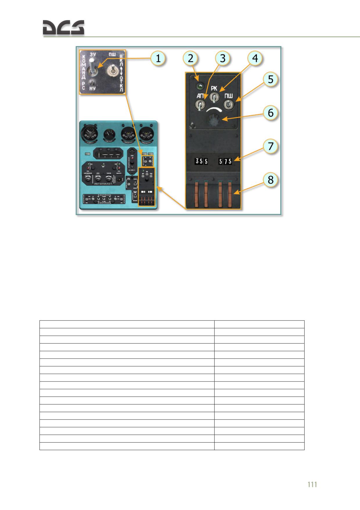
Fig. 6.3. R-863 frequency selector unit
1. "ЗУ-НУ" (PRESETS-MANUAL) switch selects
4. "РК" (RK) switch is not used on the Mi-8MT, -
between preset channels and manual frequency
MTV2..5
control;
5. "ПШ" (SQUELCH) switch to activate the noise
2. "АП" (EMERG) - lamp is not engaged on the
suppression circuit;
Mi-8MT, -MTV2..5 because there is no emergency
6. "РГ" (VOLUME) control knob;
receiver;
7. Frequency scale (now 355.575 MHz);
3. "АП" (EMERG RCVR) - switch is not engaged
8. Wheels for setting frequency.
on the Mi-8MT, -MTV2..5 because there is no
emergency receiver;
R-863 SPECIFICATIONS:
Frequency range:
VHF
100-149.975 MHz
UHF
220-399.975 MHz
Frequency separation
25 kHz
Number of discrete frequencies:
VHF
2000
UHF
7200
Power output:
VHF
10 W
UHF
8 W
Receiver sensitivity
3 µV
Emergency receiver frequency:
VHF
121.5 MHz
UHF
243 MHz
Frequency tuning time, no more than
1.5 sec
Time to readiness
5 min
Power voltage
28.5 V
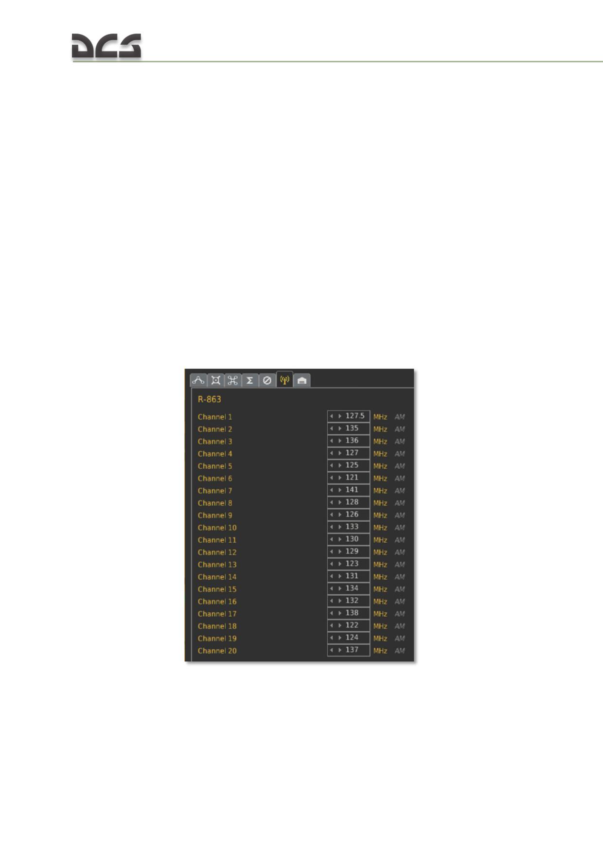
R-863 OPERATION:
Turn ON the "КОМАНД. РС" (CMND RADIO) and "СПУ" (ICS) circuit breakers on the
right circuit breaker panel. Set radio selector on the ICS control box to the "УКР"
(VHF1) position and the "СПУ-РАДИО" (ICS-RADIO) selector to the RADIO (down)
position. On the R-863 control panels:
SQUELCH (AS) switch to the OFF (down) position
AM-FM switch to the appropriate position for the desired channel
CHANNEL selector to the desired channel
volume control to maximum
In case of poor reception, turn off the squelch. To switch off the radio set, set the
"КОМАНД. РС" (CMND RADIO) circuit breaker on the right circuit breaker panel to
OFF (down).
Notes. 1. The АП (EMERG RCVR) switch, enabling the emergency receiver and сorresponding lamp
signalization when emergency signal is received, is not used, because there is no emergency receiver
on this helicopter.
2. The РК (Radio compass) switch, enabling simultaneous listening of the ARK-9 signals, is not used,
because they are listened via the SPU-7 intercom.
CONFIGURING THE R-863 CHANNEL PRESET FREQUENCIES IN DCS:
Fig. 6.4. The R-863 channel preset frequencies
6.1.3. ЯДРО-1А (YaDRO-1A) HF radio set
The YaDRO-1A HF radio set is designed to provide simplex, fixed-tuned, air-to-
ground and air-to- air voice communications. The radio set offers tuning in flight to
112
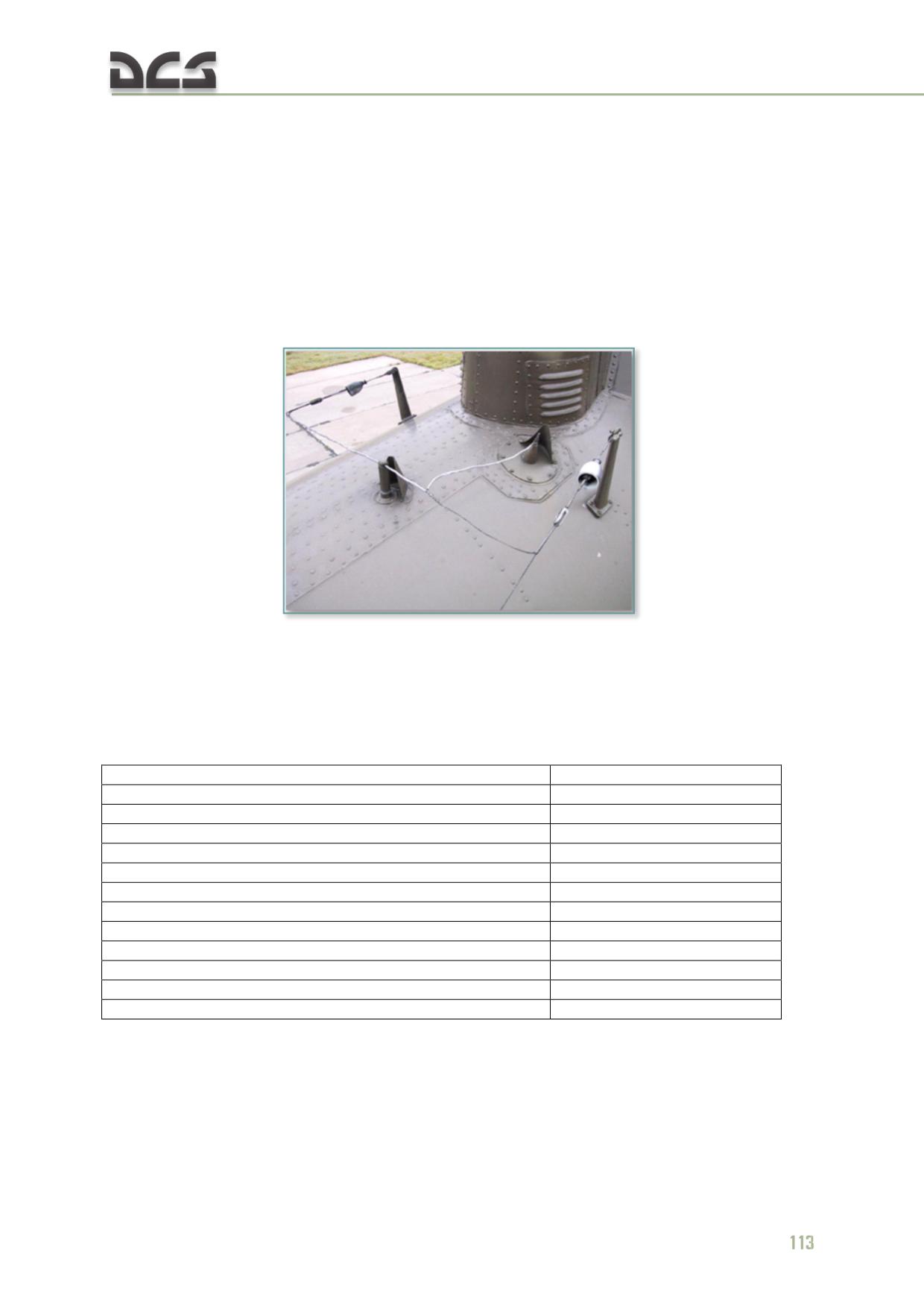
any communication frequency within a range of 2 to 17.999 MHz in 100 Hz
increments in AM or SSB (single sideband) modes. The radio set operates via a wire
antenna. The radio set is supplied with 27 VDC from the rectifier bus via the "СВЯЗН
РС" (COMM RADIO) circuit breaker on the right circuit breaker panel, and with 115
VAC from the 115 VAC primary bus via a fuse located in the main fuse box.
YADRO-1A COMPONENTS:
transceiver and automatic tuning control unit
wire antenna (steel cable strung along the upper left and right sides of the
tail boom to the outboard leading edges of the horizontal stabilizers)
Fig. 6.5. Wire antenna
control panel located on the right auxiliary panel
"СВЯЗН РС" (COMM RADIO) circuit breaker on the right circuit breaker
panel
YADRO-1A SPECIFICATIONS:
Frequency range
2-17.999 MHz
Frequency separation
100 Hz
Effective range
no less than 900 km
Time to readiness
2 min
Continuous operation time
6 hrs
Receiver sensitivity:
AM mode
5 µV
SSB mode
3 µV
Transmitter output power:
below 12.000 MHz
100 W
in range 12.000 - 17.999 MHz
50 W
Frequency tuning time
5 sec
Power voltage
28.5 V
YaDRO-1A control panel:
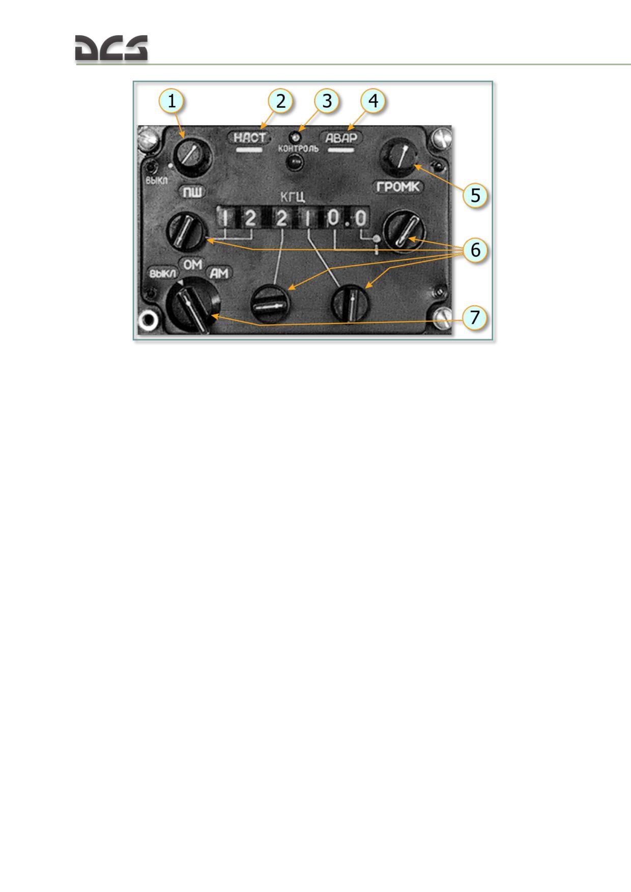
Fig. 6.6. YaDRO-1A control panel
1. "ПШ" (SQUELCH) knob for incremental control
4. "АВАР" (EMERG) light to indicate the radio set
of the noise reduction circuit;
is in emergency status;
2. "НАСТ" (TUNING) light to indicate that the
5."ГРОМК" (VOLUME) control knob;
radio set is tuning;
6. Four knobs for frequency setting;
3. "КОНТРОЛЬ" (TEST) button and light to
7. Three position selector: "ВЫКЛ" (OFF) - radio
activate and indicate progress of the radio set
set is switched off, "ОМ" (SSB), "АМ" (AM) -
self-test;
selection of operating mode.
YADRO-1A OPERATION:
Turn ON the "СВЯЗН РС" (COMM RADIO) and "СПУ" (ICS) circuit breakers on the
right circuit breaker panel. Set radio selector on the ICS control box to the "СР" (HF)
position and the "СПУ-РАДИО" (ICS-RADIO) selector to the RADIO (down) position.
On the YaDRO-1A control panel:
power up the radio set by setting the "ВЫКЛ. - ОМ - АМ" (OFF - SSB -
AM) selector to the position corresponding to the desired mode of
operation
set the "ПШ" (SQUELCH) knob to the OFF position to disable the noise
reduction circuit
set volume control to maximum
set the desired frequency using the frequency selection knobs. The
"НАСТ" (TUNING) light will illuminate. Tuning should be complete within 5
seconds and the light should go off.
A built-in test facility is provided to check the serviceability of the receive, transmit,
and tuning functions. The self-test is initiated by pressing the "КОНТР" (TEST)
button. If the radio set is operational, the "КОНТР" (TEST) light will be on and noise
heard in the headset when the radio is in receiving mode or a signal when it is in
transmission mode.
114
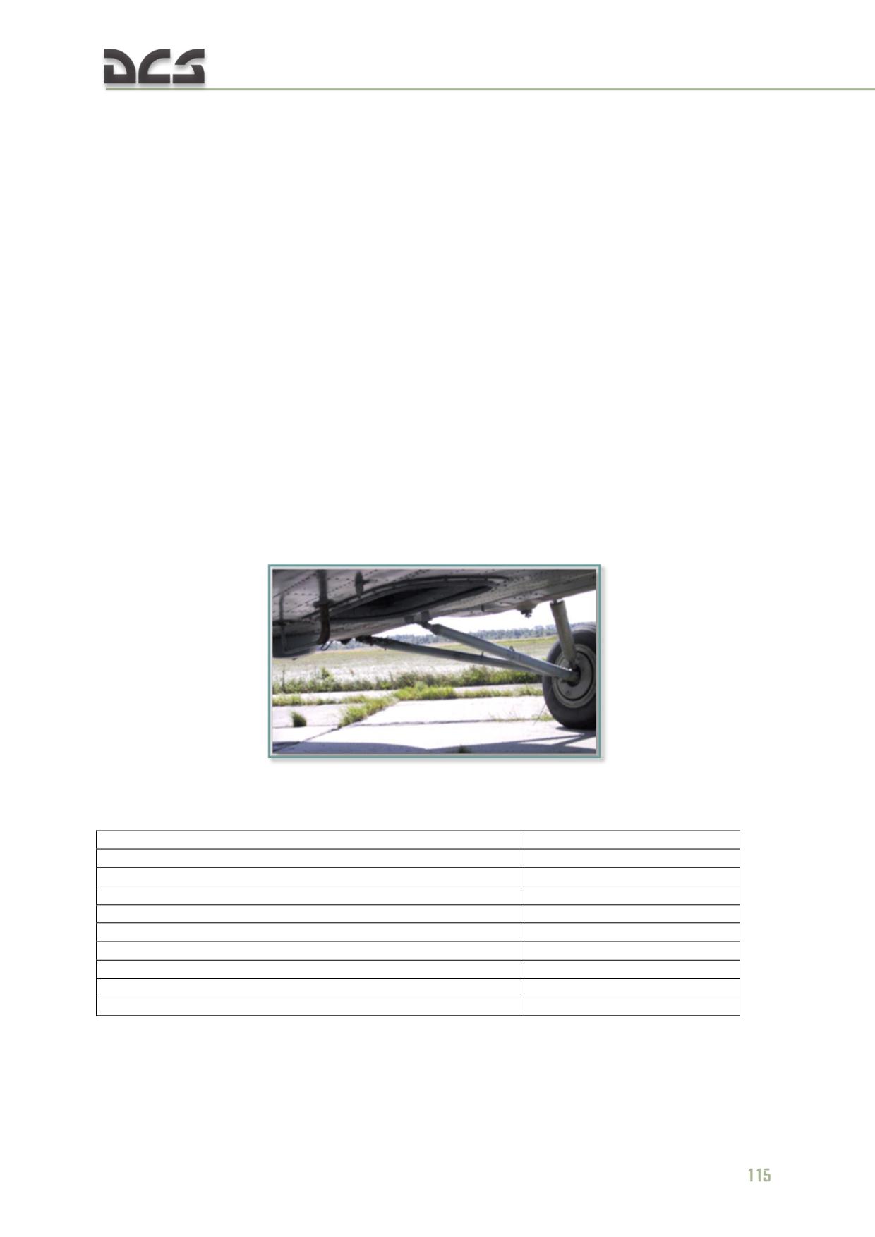
To disable the radio set, set the "СВЯЗН РС" (COMM RADIO) circuit breaker on the
right circuit breaker panel to OFF (down).
6.1.4. Р-828 (R-828) LVHF FM transceiver set
The R-828 LVHF FM transceiver set provides VHF homing in conjunction with the
"АРК-УД" (ARK-UD) VHF homing set and standby 2-way voice communications. The
radio provides instant tuning to one of ten frequencies preset on the ground. The
frequency range is 20 - 59.975 MHz in 25 kHz increments.
The radio set operates in one of two modes: VOICE (voice communication) and
HOMING (VHF homing using the ARK-UD system).
R-828 COMPONENTS:
transceiver
control panel located on the right auxiliary panel;
"Р-828 ВКЛ - ВЫКЛ" (R-828 RADIO) power switch and "Р-828 КОМПАС-
СВЯЗЬ" (R-828 VOICE-HOMING) mode switch located on the right
auxiliary panel
the NIPV-type antenna mounted at the bottom of the fuselage. The
antenna-feeder system includes a phase sensor, an antenna matching
device, and an automatic tuning control unit
Fig. 6.7. NIPV-type antenna of the R-828 radio set
R-828 SPECIFICATIONS:
Frequency range
20-59.975 MHz
Frequency separation
25 kHz
Time to readiness, no more than
3 min
Number of discrete frequencies
1600
Number of preset channels
10
Receiver sensitivity, at least
2 µV
Transmitter output power
10 W
Effective range at altitude of 1000 m
120 km
Frequency tuning time, no more than
5 sec
Power voltage
28.5 V
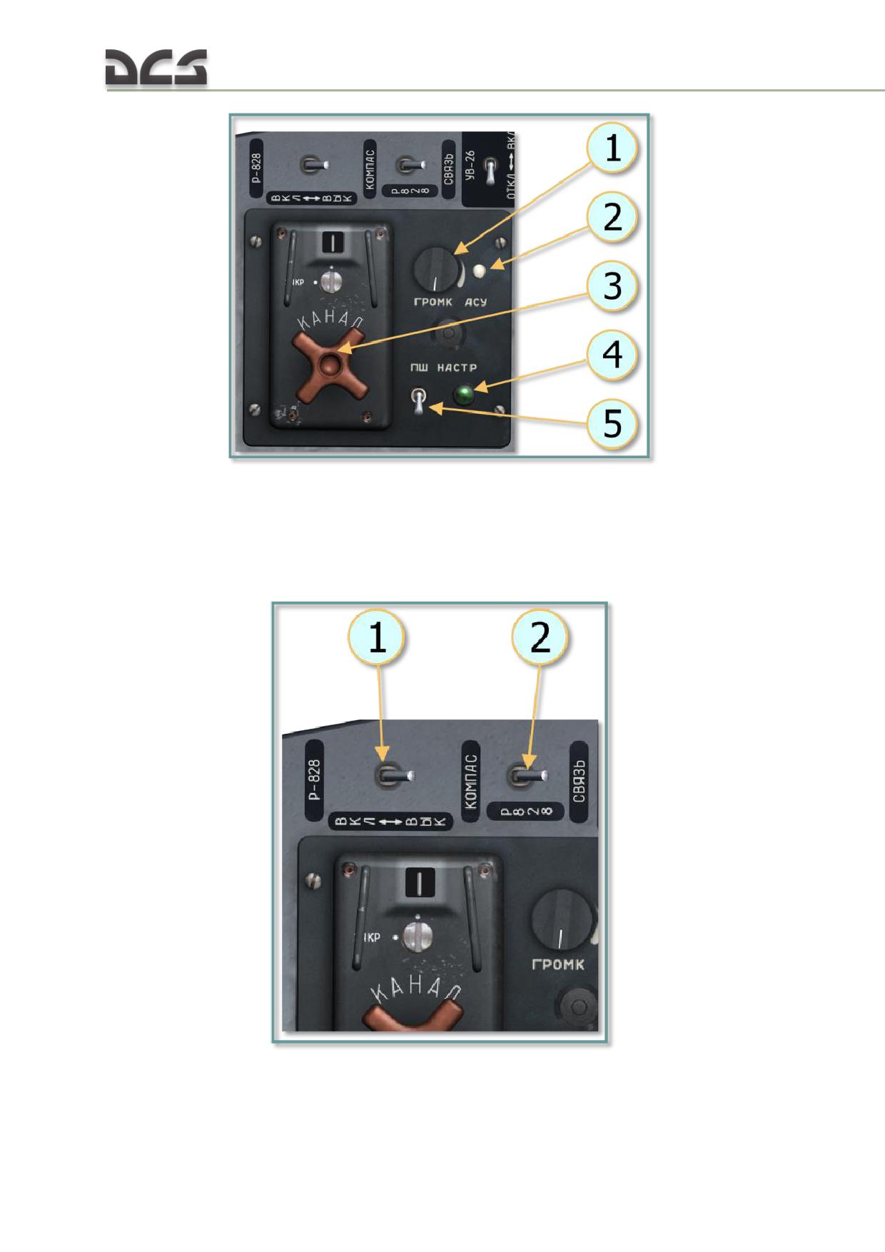
Fig. 6.8. R-828 radio set control panel
1. "ГРОМК" (VOLUME) control knob;
3. "КАНАЛ" (CHANNEL) selector to set one of 10
2. "АСУ" (AGC, automatic gain control) button to
preset frequencies;
enable automatic gain control to adapt the output
4. "НАСТР" (TUNING) light;
of the transmitter to the antenna;
5. "ПШ" (SQUELCH) switch.
Fig. 6.9. R-828 power and mode switches
1. "Р-828 ВКЛ - ВЫКЛ" (R-828 RADIO) power
2. "Р-828 СВЯЗЬ - КОМПАС" (R-828 VOICE-
switch;
HOMING) mode switch.
116
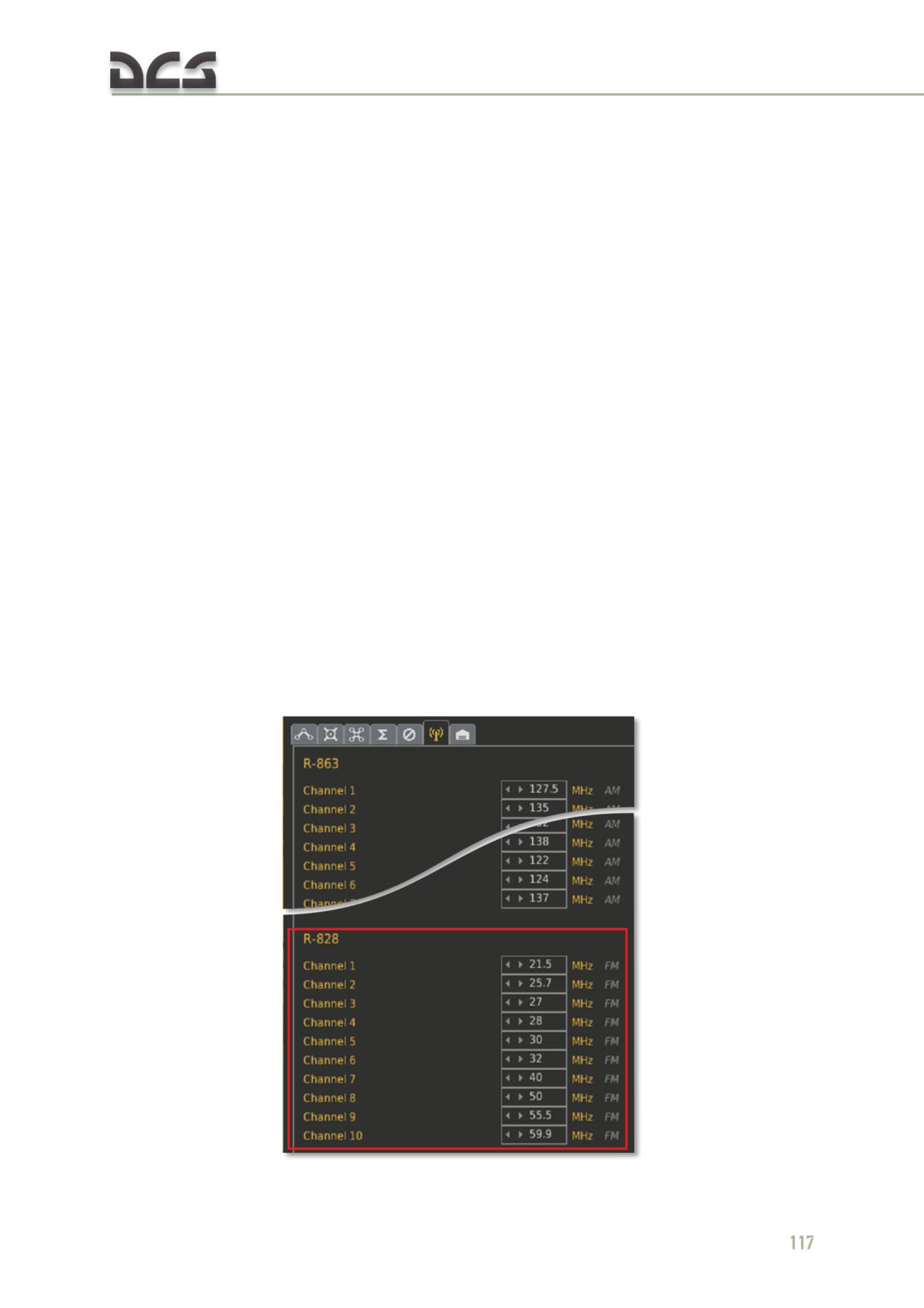
R-828 OPERATION:
Turn ON the "СПУ" (ICS) circuit breaker on the right circuit breaker panel. Set radio
selector on the ICS control box to the "КР" (KR) position and the "СПУ-РАДИО" (ICS-
RADIO) selector to the RADIO (down) position.
On the right auxiliary panel:
turn on (set forward) the "Р-828 ВКЛ - ВЫКЛ" (R-828 RADIO) switch
set the "Р-828 СВЯЗЬ-КОМПАС" (R-828 VOICE-HOMING) switch to
"СВЯЗЬ" (VOICE) (set back)
On the R-828 radio set control panel:
"ПШ" (SQUELCH) switch OFF
"ГРОМК" (VOLUME) control to maximum
"КАНАЛ" (CHANNEL) selector to the desired channel. "НАСТР" (TUNING)
light should turn on for 1-5 sec.
To disable the radio set, set the "Р-828 ВКЛ - ВЫКЛ" (R-828 RADIO) switch to the
"ВЫКЛ" (OFF) position (back).
To use the R-828 radio in conjunction with the ARK-UD homing set to home on to a
ground station, first establish voice contact with the station and request a tone
modulated signal from the ground station operator for the desired frequency. Once
the tone signal is confirmed in the headset, set the Р-828 СВЯЗЬ-КОМПАС" (R-828
VOICE-HOMING) mode switch to "КОМПАС" (HOMING). Observe the needle on the
UGR-4UK directional gyro for signal bearing.
CONFIGURING THE R-828 CHANNEL PRESET FREQUENCIES IN DCS:
Fig. 6.10. The R-828 channel preset frequencies
6.1.5. РИ-65 (RI-65) audio warning system
The RI-65 audio warning system is designed to alert the crew of in-flight emergency
situations over the intercom system. The audio warning system consists of a control
unit which receives input from the onboard sensors and plays back the appropriate
advisories and a control panel which allows for testing, repeating an advisory, and
shutting off an advisory message. The audio warning unit is installed in the radio
compartment on the left side. The control panel is located in the upper center area
of the left side console.
The audio warning unit automatically broadcasts the recorded advisory message over
the intercom when an activation signal is received from the onboard sensors. The fire
warning messages (channels 1 through 4) are also automatically broadcast over the
VHF (R-863) radio. If multiple alerts occur simultaneously, audio warnings are
broadcast in order of priority.
The following advisories are recorded:
Aircraft (tail #)... fire in left engine compartment
Aircraft (tail #)... fire in right engine compartment
Aircraft (tail #)... fire in transmission compartment
Aircraft (tail #)... fire in heater compartment
Dangerous vibration, left engine
Dangerous vibration, right engine
Main hydraulic system failure
Low fuel emergency
Service cell fuel pump failure, check remaining fuel
Saddle tank fuel pump failure
Ice formation warning
Generator 1 failure
Generator 2 failure
Audio warning system operational
RI-65 components:
message broadcasting equipment
switch and warning annunciator "ВКЛЮЧИ РИ-65" (TURN ON RI-65) on
the left triangular panel, Fig. 6.11
control panel, Fig. 6.12
118
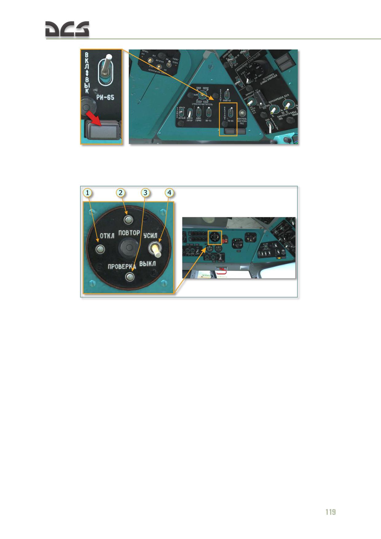
Fig. 6.11. Switch and warning annunciator "ВКЛЮЧИ РИ-65" (TURN ON RI-65)
on the left triangular panel
Fig. 6.12. Control panel of audio warning system RI-65
1. Button ОТКЛ. (OFF) for turn off listening
3. Button ПРОВЕРКА (TEST) is designed to
information and switching R-863 from the
test equipment operability
transmit mode to the receive mode
4. Swith УСИЛ (GAIN) is not engaged
2. Button ПОВТОР (REPEAT) for replay the
current voice message
The warning annunciator is removed when the system is turned on with the "РИ-65"
(AUDIO WARN) switch.
The audio warning system receives 27 VDC from the battery bus. The system is
engaged using the "РИ-65" (AUDIO WARN) switch located on the left triangular
panel.
6.2. Radio navigation systems
Radio communication systems installed on the Mi-8MTV2 include:
АРК-9 (ARK-9) automatic direction finding (ADF) set
АРК-УД (ARK-UD) VHF homing set
ДИСС-15 (DISS-15) Doppler navigation set
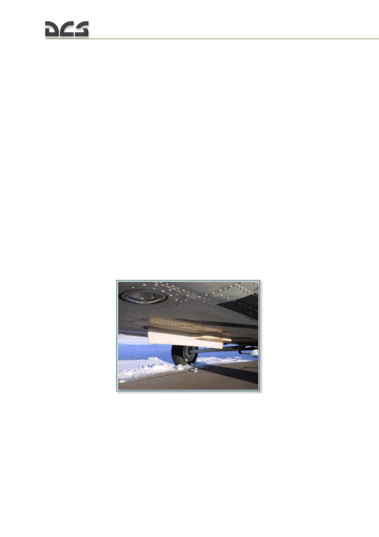
РВ-5 (RV-5) radar altimeter set
6.2.1. АРК-9 (ARK-9) automatic direction finding (ADF) set
The ARK-9 ADF set is designed to use non-directional radio beacons (NDB),
broadcasting radio stations or compass locators for in-flight navigation. Frequency
range of the set is 150 to 1300 kHz. The relative bearing is displayed by needle No. 1
(narrow) on the UGR-4UK directional gyro on the pilot and copilot instrument panels.
The LF-ADF is used for the following situations:
Flying to or from a radio station or NDB with visual display of the relative
bearing.
Station identification by monitoring the audio call signs.
Determination and continuous display of the relative bearings to a radio
beacon or broadcasting radio station.
Performing non-precision instrument landing approaches or navigating to
the inner and outer ILS marker beacons.
The ADF can be used as a reserve voice communication receiver. Three operating
modes are provided: "АНТ." (ANT, antenna), "КОМП." (COMP, compass), "РАМК."
(LOOP).
ARK-9 сomponents:
receiver unit;
power supply;
antenna assembly in a common housing along the bottom of the fuselage;
Fig. 6.13. Loop antenna and nondirectional antenna
remote tuner switching unit;
control panel on the right overhead console;
"АРК СВ - АРК УКВ" (ADF-MW - ADF USW) switch on the left instrument
panel under the UGR-4UK directional gyro to select between ARK-9 and
ARK-UD to drive the bearing needle;
"КОМПАС СВ" (COMPASS MW) circuit breaker on the right circuit breaker
panel.
120
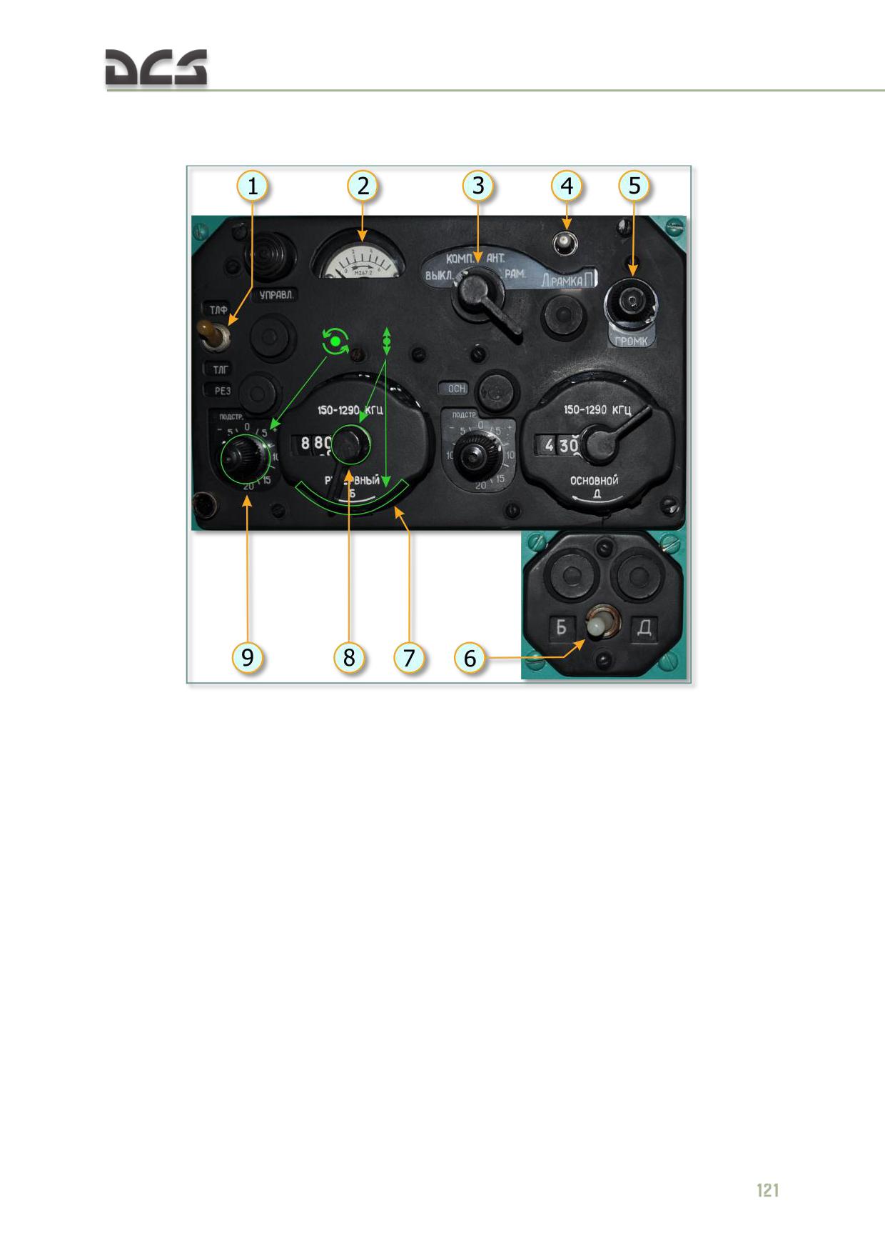
Heading/bearing information is displayed on the UGR-4UK directional gyros on the
left and right instrument panels.
Fig. 6.14. ARK-9 control panel
1. "ТЛФ-ТЛГ" (VOICE - CW) switch
4. "Л рамка П" (LOOP) spring-load switch.
2. Signal power indicator
Initiates manual rotation of the search coil
3. "АРК ВЫКЛ., КОМП., АНТ., РАМ." (OFF -
5. "ГРОМК." (GAIN) volume control knob
COMP - ANT - LOOP) mode selector:
6. "Б - Д" (B - D CHANNEL) switch to select main
"ВЫКЛ." (OFF): powers down the ADF
("Д" (D), right) or reserve ("Б" (B), left) channel
set;
frequency
"КОМП." (COMP, compass): powers up
and prepares the set for operation in
7-9 FREQUENCY SETTING DIALS:
ADF mode, audio monitoring of the
The 100 kHz (7) and 10 kHz (8) discrete
selected frequency and automatic
frequency dials (switch and drum) set the main
direction finding are functional. Primary
(right dial) and reserve (left dial) frequency in the
operating mode;
range of 150 kHz - 1290 kHz in 10 kHz steps. The
"АНТ." (ANT, antenna): allows audio
"НАСТР." (TUNE) knobs (9) adjust the set
monitoring of the selected frequency for
frequency from -10 kHz to +20 kHz;
tuning or for listening to call letters of
signal tones, no direction finding occurs
"УПРАВЛ." (CONTROL) button. Not utilized
in this mode;
"РАМ." (LOOP): allows audio monitoring
of the loop antenna output for direction
finding by ear, based on signal fade in
and out if the COMPASS mode fails
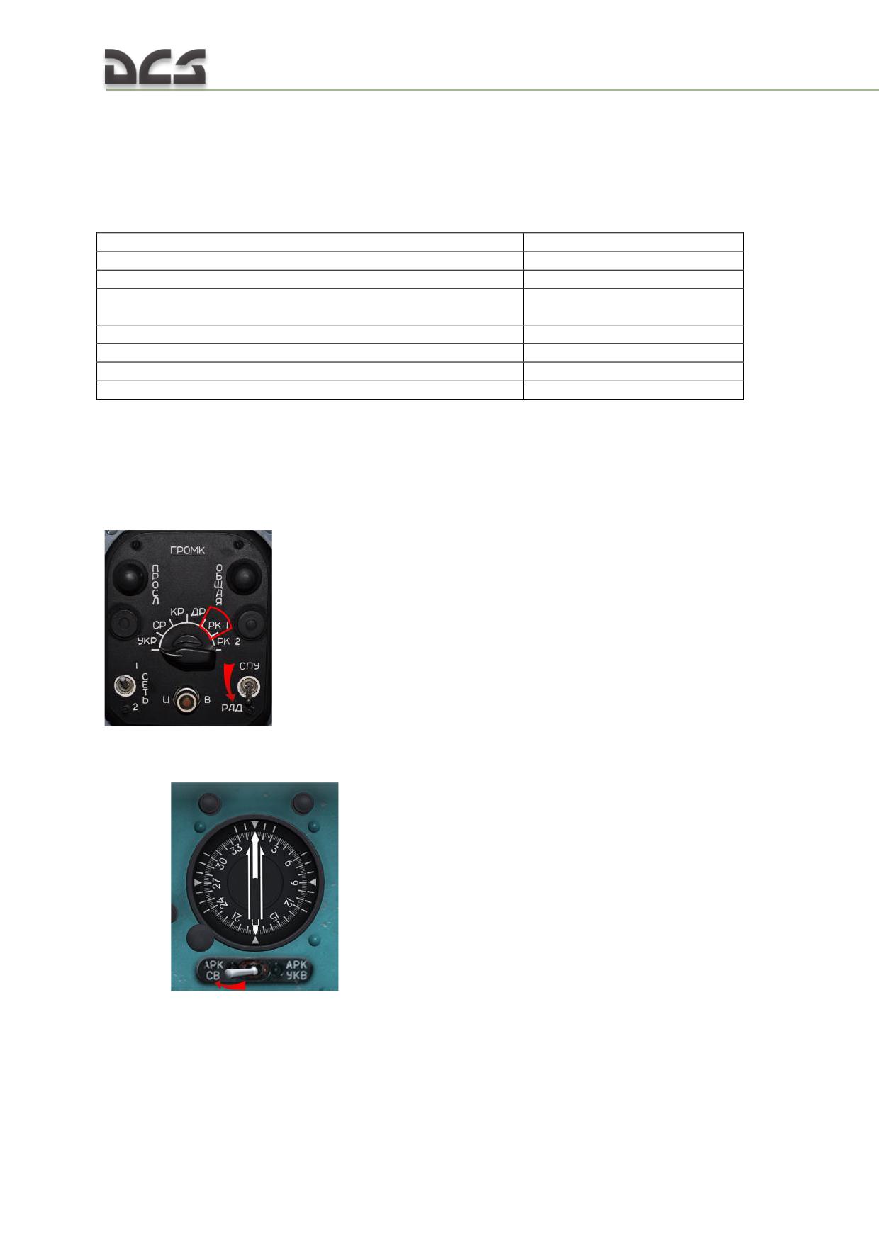
Set to "ТЛФ" (VOICE) to monitor a broadcasting station or demodulate a carrier
signal to identify locator beacon call letters. Set to "ТЛГ" (CW) to home on a
continuous wave signal. SPU-7 source selector must be set to "РК 1" (ADF) for signal
to be heard in headset;
ARK-9 SPECIFICATIONS:
Frequency range
150-1300 kHz
Frequency tuning precision
±10 kHz
Frequency separation
10 kHz
Effective homing range to ПАР-10 (PAR-10) type NDB at an
no less than 160 km
altitude of 1000 m
Channel switching time
2-4 sec
Signal bearing error
no more than 2°
Time to readiness
1-2 min
Receiver sensitivity in ANT mode
5-8 µV
ARK-9 OPERATION:
1. Turn on the ARK-9 LF-ADF set (27V, 115V 400Hz) and the ICS with the "КОМПАС
СВ" (COMPASS MW) and "СПУ" (SPU) circuit breakers on the right circuit breaker
panel.
2. Set the source selector on the ICS control box to the "РК
1" (ADF1)
position and the "СПУ-РАДИО" (ICS-RADIO) selector to the
"РАД" (RADIO, down) position.
3. Set the selector knob for the UGR-4UK needle No.1 to the "АРК-СВ" (ADF-MW)
position
for visual bearing needle control by the ARK-9 LF-ADF
system.
4. On the ARK-9 control panel (Fig. 6.14):
o mode selector to "AНТ" (ANT) (3);
122
o "ТЛФ - ТЛГ" (VOICE - CW) switch to "ТЛГ" (CW). A signal should be
heard in the headset and disappear when the switch is set to "ТЛФ"
(VOICE) (1);
o "ГРОМК." (GAIN) volume control to maximum (5);
o "Б - Д" (B - D CHANNEL) switch to "Б" (B, reserve channel) (6);
o dial the frequency of the desired beacon using the left frequency
setting dial and confirm the beacon call letters (Morse ID) (7-9)
o mode selector to "КОМП." (COMP) (3). The No.1 bearing indicator on
the UGR-4UK directional gyro should display the bearing to the selected
beacon transmitter
o press the "Л-РАМКА-П" (LOOP) switch (4) to turn the No.1 arrow on
the directional gyro 150° - 170° off the beacon bearing. Upon releasing
the switch, confirm the No.1 arrow returns to the correct beacon
bearing.
5. Set the "Б - Д" (B - D CHANNEL) switch (Fig. 6.14, 6) to "Д" (D, main channel)
and tune the main channel following the same process as the reserve channel.
In case radio interference hampers operation of the ADF, use the "Л-РАМКА-П" (Fig.
6.14, 4) (LOOP) mode to determine bearing to the transmitter based on fading signal
volume (Fig. 6.14, 2).
6.2.2. АРК-УД (ARK-UD) VHF homing set
The ARK-UD VHF homing set is designed primarily for search and rescue of downed
aircraft and aircrews. The system will home on radio stations (beacons), such as Р-
855УМ (R-855UM) portable emergency radio, emitting CW or pulse signals over one
of six VHF or one UHF preset frequencies. The secondary purpose of the system is to
direct aircraft to airfields using VHF ground stations and assist in joining aircraft in
flight.
The ARK-UD provides:
homing on VHF and UHF beacons for search and rescue helicopters
Indication of the moment a homing beacon is flown over by a reversal of
the bearing indicator on the directional gyro.
audio identification of a homing beacon by the pilot
ARK-UD СOMPONENTS:
loop antenna installed on the bottom of the center fuselage
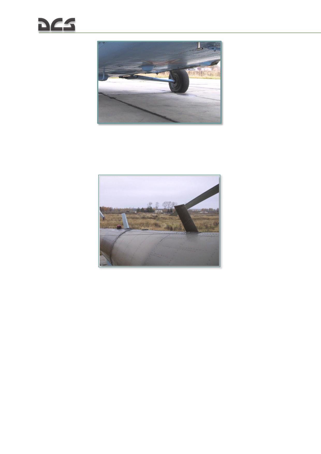
Fig. 6.15. ARK-UD loop antenna housing
antenna amplifier
control panel located on the right overhead console
direction-finding receiver
АШС-УД (AShS-UD) blade antenna on the tail boom
Fig. 6.16. AShS-UD blade antenna
"БЛОКИРОВКА АРК-УД" (VHF-ADF INTERLOCK) switch on the right
triangular panel used to prevent interference with the R-863 radio
"РАДИОКОМПАС УКВ" (ARK-UD) circuit breaker on the right circuit
breaker console
"АРК СВ - АРК УКВ" (ARK-MW - ARK-USW) switch on the left instrument
panel to select between ARK-9 and ARK-UD bearing source for the
directional gyro indicator.
Operation in VHF and UHF bands is less accurate than MW due to:
1. VHF and UHF wavelengths affected by fuselage elements of equal size causing
directional error in the bearings displayed by the directional gyro. In this case the
ARK-UD provides only a general direction to the beacon.
2. VHF wavelengths being reflected by fuselage elements causing the bearing
indicator to oscillate as the helicopter approaches the homing beacon.
ARK-UD SPECIFICATIONS:
124
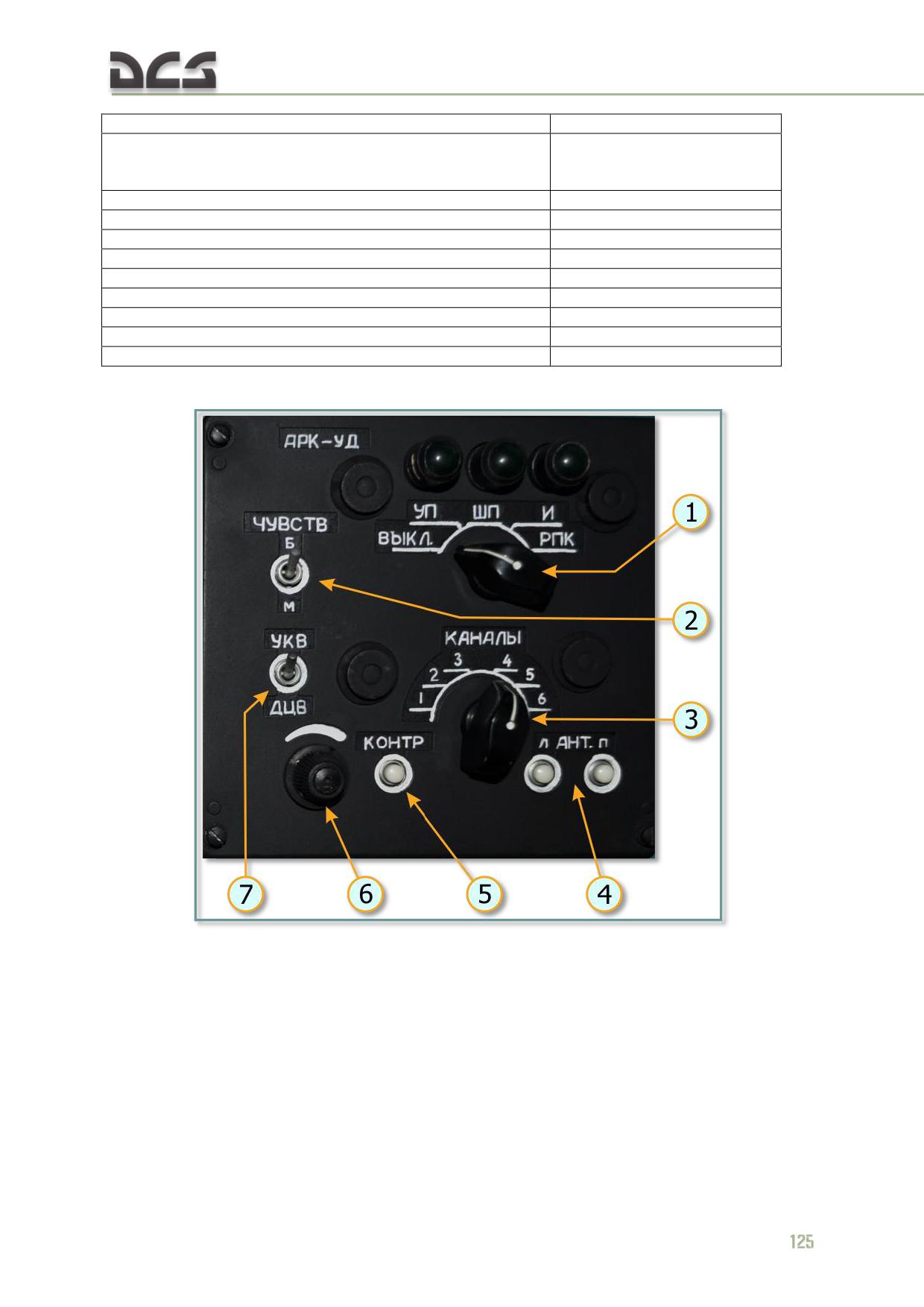
VHF frequency range
114.166-124.1 MHz
VHF preset frequencies
114.166 МГц; 121.5 MHz
114.333 МГц; 123.1 MHz
114.583 МГц; 124.1 MHz
UHF frequency range
243-248 MHz
UHF preset frequency
243 MHz
Effective range to R-855UM type beacon at altitudes:
3000 m
55 km
1000 m
35 km
500 m
25 km
300 m
15 km
Bearing error
no more than ±3
Beacon location error at altitude of 1000 m
no more than ±200 m
Fig. 6.17. ARK-UD control panel
1. "ВЫКЛ., УП., ШП, И, РПК." (OFF - NARROW
3. "КАНАЛЫ" (CHANNEL) selector: sets preset
BAND - WIDE BAND - PULSE - RPK) MODE
VHF frequency
selector:
4. "Л -АНТ.- П." (ANTENNA L/R) buttons: pressed
"ВЫКЛ." (OFF): ARK-UD system is
to manualy rotate loop antenna left or right
switched off
5. "КОНТР." (TEST) button: self-test mode
"УП" (NARROW BAND): CW narrow band
operation
reception, illuminates corresponding
6. Volume control knob
lamp
7. "УКВ-ДЦВ" (FQ BAND) switch: sets VHF (up)
"ШП" (WIDE BAND): CW wide band
or UHF (down) operating band. When set to VHF,
reception, illuminates corresponding
use channel selector to tune receiver to the
lamp
desired frequency channel. When set to UHF,
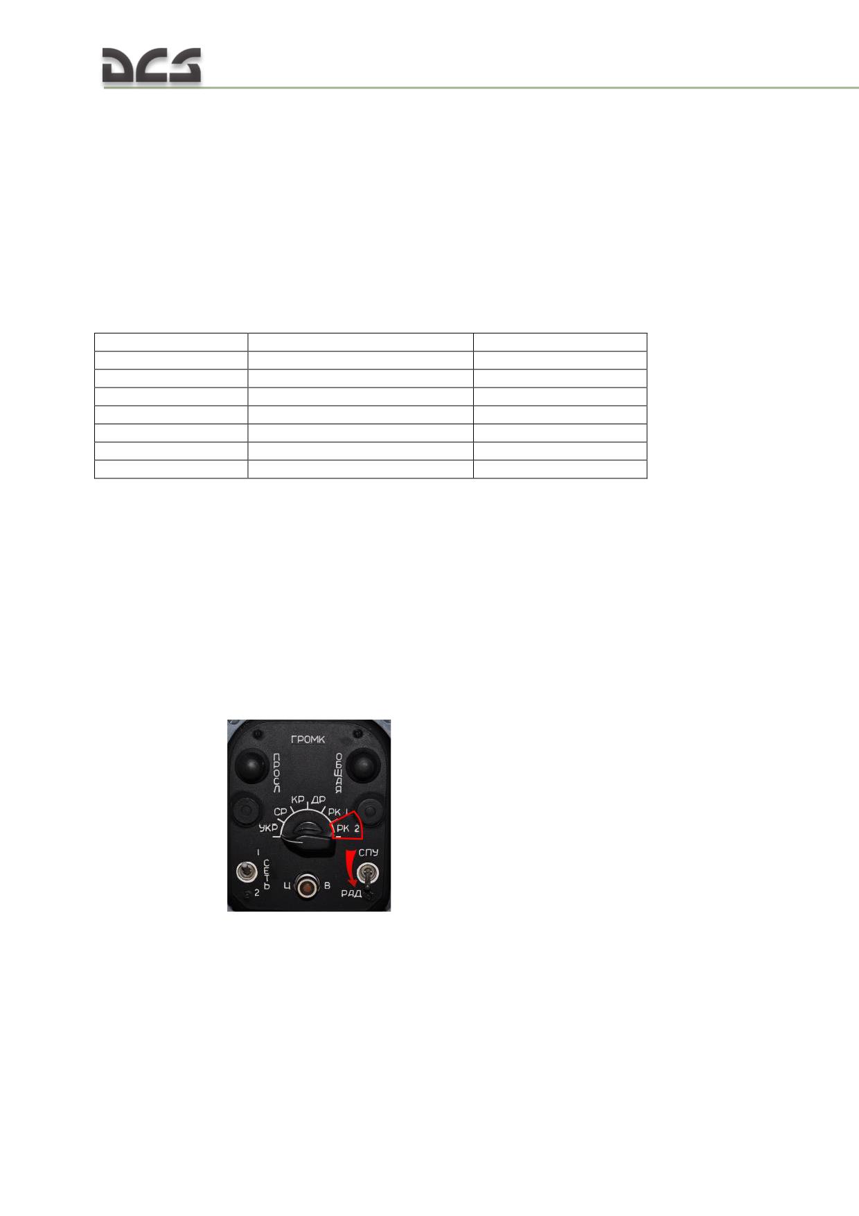
"И" (PULSE): the homing channel
receiver tunes to 243.000 MHz
transduces 40 µs pulse signals sent at
300 Hz while the audio output channel
operates over the wideband component
of the receiver. Operation in PULSE
mode illuminates the corresponding
"РПК" (RPK): not utilized
2. "ЧУВСТВ. Б-М" (SENSITIVITY HIGH - LOW)
switch: sets antenna sensitivity for the homing
channel
The ARK-UD operates on the following preset frequencies:
Band
Frequency, МНz
Channel #
VHF
114.166
1
VHF
114.333
2
VHF
114.583
3
VHF
121.5
4
VHF
123.1
5
VHF
124.1
6
UHF
243.0
any
In TEST mode, the bearing needle of the UGR-4UK directional gyro points to
180°±10° and the currently set operating mode lamp illuminates.
Heading/bearing information is displayed on the UGR-4UK directional gyros on the
left (only) instrument panels.
ARK-UD OPERATION:
1. Turn on the ARK-UD ADF set
(27V,
115V
400Hz) and the ICS with the
"РАДИОКОМПАС УКВ" (ARK-UD) and "СПУ" (SPU) circuit breakers on the right
circuit breaker panel. Set the source selector on the ICS control box to the "РК 2"
(SAR) position (only required for audio signal monitoring; not required for radio
compass operation) and the "СПУ-РАДИО" (ICS-RADIO) selector to the RADIO
(down) position
126
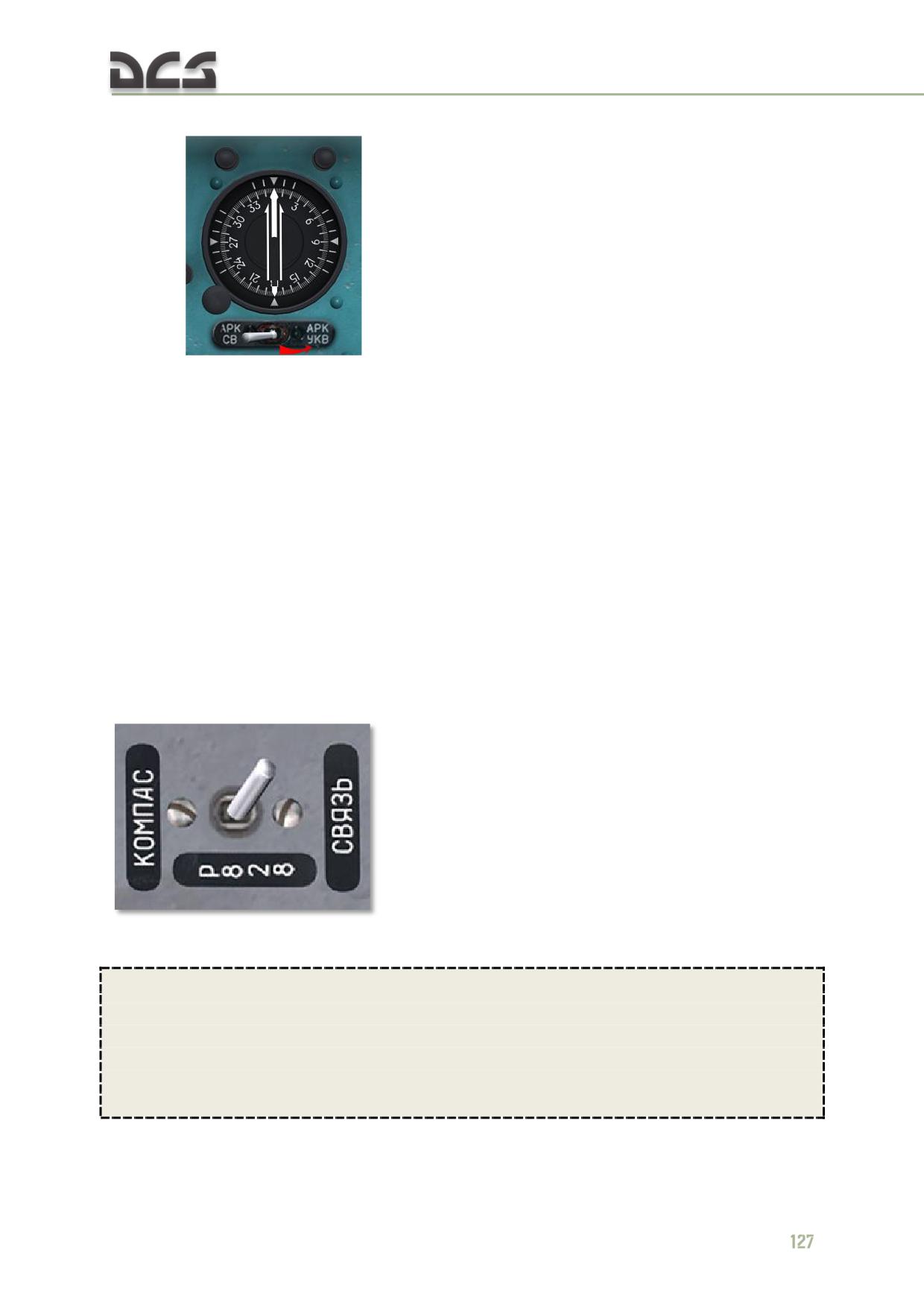
2. Set the selector knob for the UGR-4UK needle No.1 to the "АРК-УКВ" (ADF-USW)
position f
or bearing needle control by the ARK-UD system.
3. On the ARK-UD control panel (Fig. 6.17):
MODE selector (1) set to "УП" (NARROW BAND). When the "ШП" (WIDE
BAND) lamp illuminates as the helicopter nears the beacon, switch to ШП
(WIDE BAND) mode
FQ BAND switch (7) and CHANNEL selector (3) set to correspond to
required band and channel for reception of desired signal. If operating in
UHF mode, channel setting is irrelevant.
4. Ready.
In PUSLE mode, a tone signal with a reduced frequency is heard in the headset (not
currently implemented in DCS).
The ARK-UD set can be utilized in conjunction with the R-828 radio set allowing for
homing on frequencies outside the normal ARK-UD presets. Selection of R-828
antenna is made by setting the "Р-828 СВЯЗЬ - КОМПАС" (R-828 VOICE-HOMING)
mode switch on the right auxiliary panel to "КОМПАС" (COMASS)
For more information, see the R-828 section of the manual.
ARK-UD operation in DCS:
Utilizing the ARK-UD set in DCS requires that a transmitter is created and added to
the world by placement on the map or attached to an airborne or ground unit. The
transmitter must be configured to transmit over the correct frequency and
modulation setting compatible with the ARK-UD set. See the DCS User Manual for
more information on unit placement and configuration in DCS World.
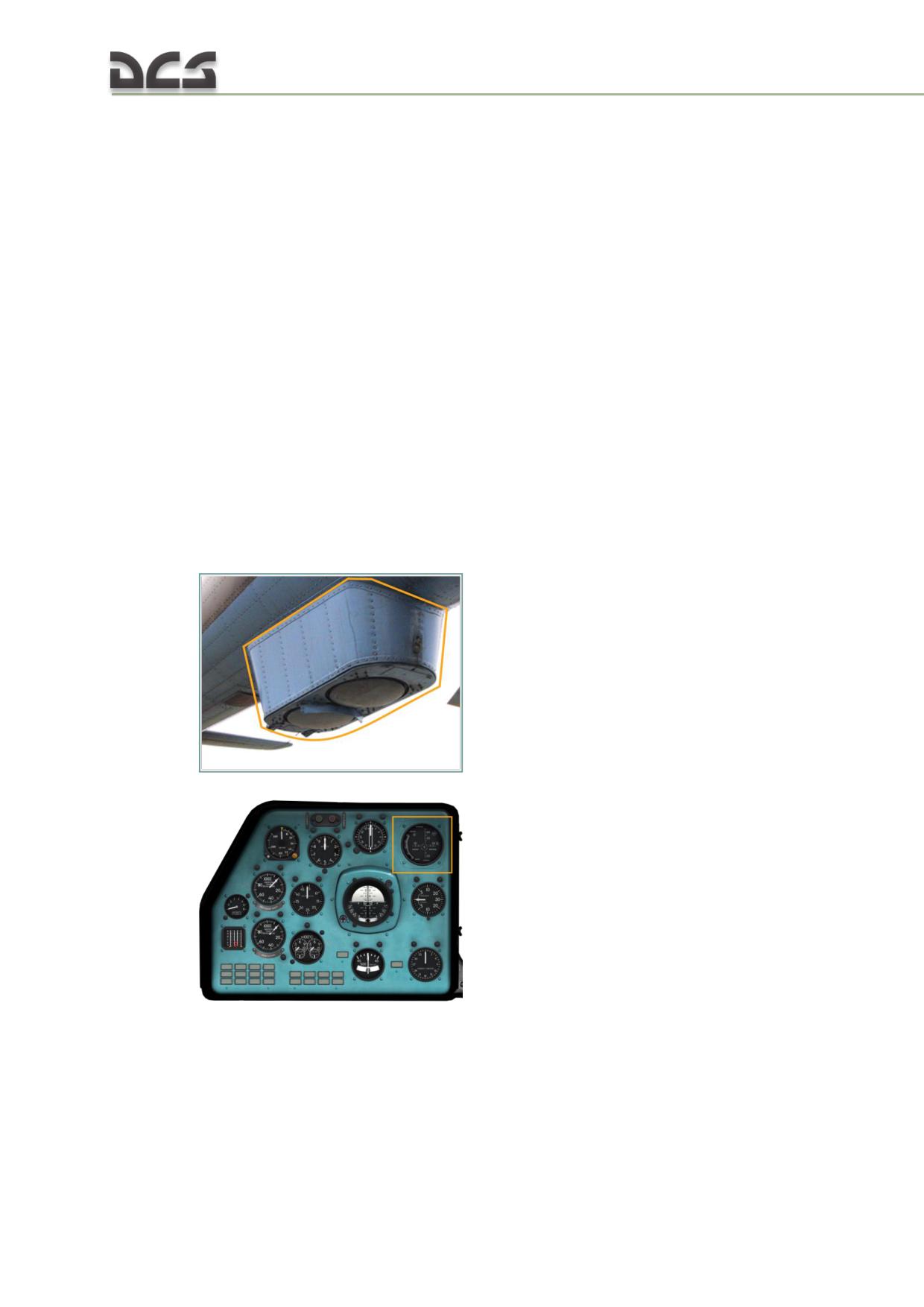
6.2.3. ДИСС-15 (DISS-15) doppler navigation set
The DISS-15 Doppler system, operating in conjunction with the AGB-3K gyro-horizon
and the GMK-1A gyro-compass system, is designed for continuous automatic
measurement and display of the ground speed components in the low speed (hover)
mode; ground speed and drift angle in the navigation mode; computation and
indication of the helicopter positional coordinates; and for delivery of these data to
other onboard systems.
The Doppler system, in conjunction with other onboard instruments (i.e., autopilot,
radar altimeter, etc.) assists the pilot in solving the following navigational and flight
problems:
navigation to waypoint coordinates;
precision approaches;
hovering and landing when current wind information is not available;
hovering and controlling helicopter movement in poor visibility or IMC.
DISS-15 COMPONENTS:
low frequency unit (inside of tailboom);
coordinate computer (inside of tailboom);
high frequency unit (underside of the tail boom)
;
stationary flight indicator located on the pilot's (left) instrument panel
;
128
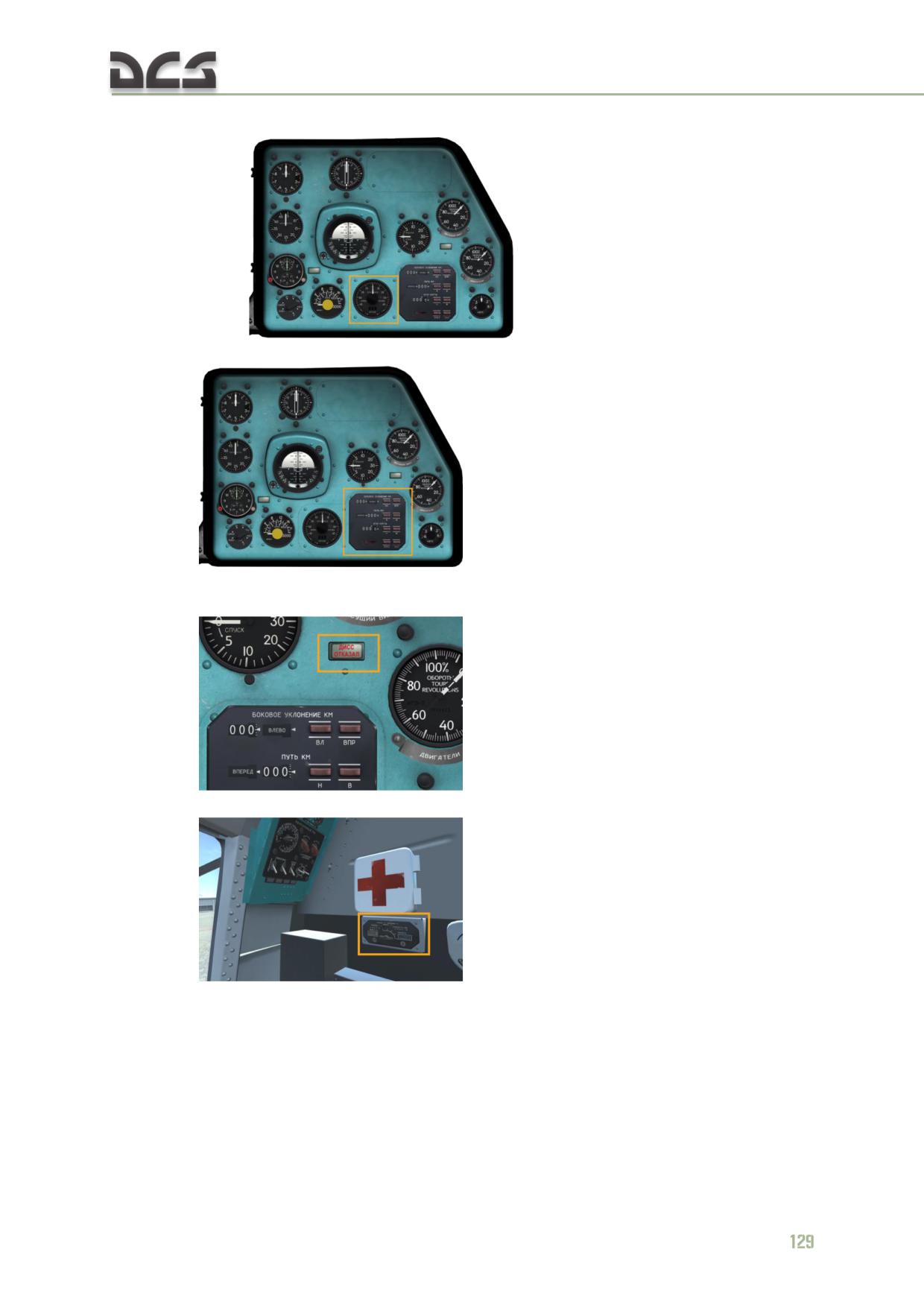
ground speed and drift angle indicator on the copilot (right) instrument
panel
;
digital display unit located on the copilot instrument panel
;
"ДИСС ОТКАЗАЛ" (DISS FAILURE) light on the copilot instrument panel
(illuminates when the system is in MEMORY mode or in case of failure)
;
control panel on the right rack in the cockpit (behind the copilot)
;
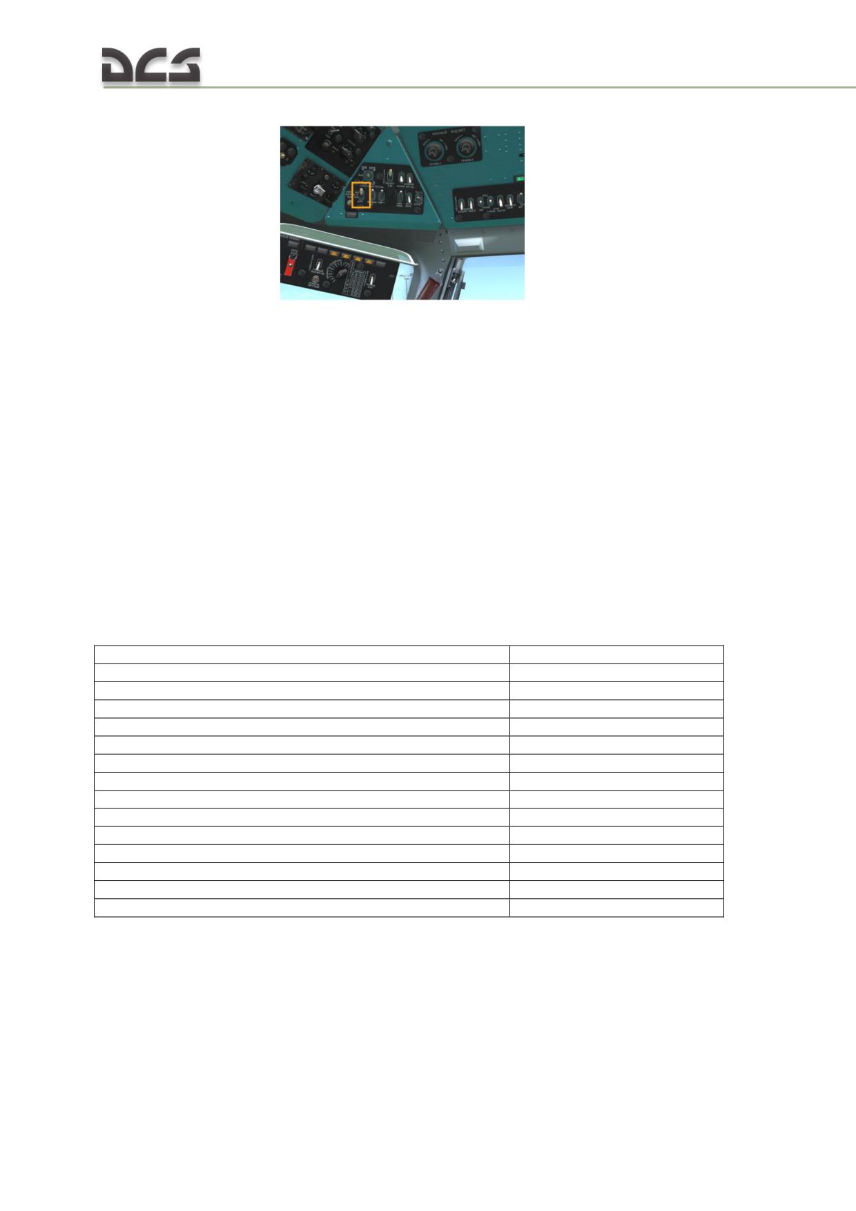
"ДИСС" (DOPPLER) circuit breaker on the right circuit breaker console and
DISS switch
The Doppler transceiver/antenna unit is located at the bottom of the tail boom. It
generates, transmits, and receives microwave energy. It sends the energy it receives
to the low frequency signal converter unit for conversion into DC signals that are
proportional to the lateral, longitudinal, and vertical components of ground speed.
The unit is equipped with a fan for air cooling.
Ground speed data is supplied to the following indicators:
low speed (hover) indicator;
ground speed and drift angle indicator;
digital display unit.
When flying over water with a sea state of greater than 1 - 2, the Doppler system
switches to MEMORY mode. Previously measured readings are displayed on the
indicators. The system also switches to MEMORY mode at roll angles of greater than
30° and pitch angles of greater than 7°.
DISS-15 SPECIFICATIONS:
Emission type
continuous
Emission frequency
13325 + 20 - 30 MHz
Emission power output
no less than 2 W
Altitude limits
10-3000 m
Altitude limits in hover mode:
over land surface
2-1000 m
over water surface (sea state greater than 1)
2-500 m
Measured ground speed range
0-400 km/h
Measured drift angle range
±45°
Measurement error:
ground speed
0.5% ± 1, 5 km/h
drift angle
25 minutes
coordinates
1% ± 1 km/h
Longitudinal and lateral components calculation error
± 1.5 km/h
Vertical component calculation error
± 0.4 m/s
DISS-15 DOPPLER SYSTEM CONTROLS AND INDICATORS:
DOPPLER CONTROL PANEL: used to select the operating mode of the system and to
introduce three test functions. Additionally, the following failures are continually
monitored and reported by the system:
the ground speed and drift angle indicator "П" (P) warning light
illuminates whenever the radio signal ground return is too weak or absent
130
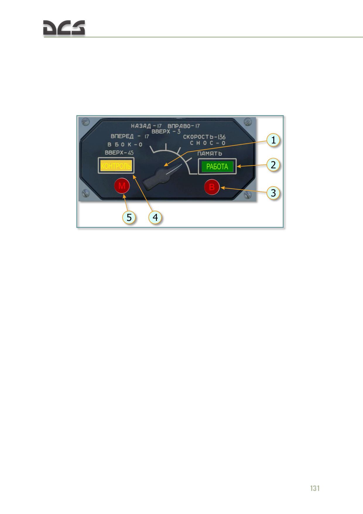
the Doppler control panel "M" (M) warning light illuminates in case of
Doppler system magnetron failure
the Doppler control panel "В" (V) warning light illuminates in case of
Doppler computer failure
The "ДИСС ОТКАЗАЛ" (DISS FAILURE) annunciator on the copilot instrument panel
illuminates whenever either the "М" (M) or "В" (V) light illuminates on the Doppler
control panel.
Fig. 6.18. Doppler control panel
1. MODE selector: positions 1-4 perform test
3. "В" (V) light: illuminates if the Doppler
functions and do not initiate radio emissions.
computer fails;
Position 5, "РАБОТА" (OPERATE) is the normal
4. "КОНТРОЛЬ" (TEST) light: indicates the
functional mode and initiates radio emissions and
system is in test mode;
measurement of ground speed and drift angle
5. "М" (M) light: illuminates in the event of
components;
magnetron failure.
2. "РАБОТА" (OPERATE) light: indicates the
system is operating normally;
STATIONARY FLIGHT INDICATOR: continuously displays the vertical, lateral, and
longitudinal components of helicopter ground speed during hover and low speed
flight.
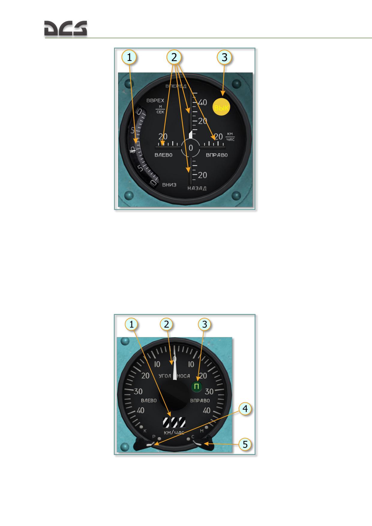
Fig. 6.19. Stationary flight indicator
1. Vertical pointer: displays vertical speed within
3. "ВЫК." (OFF) light: illuminates whenever:
a range of ±10 m/s on a scale graduated to 1
forward speed passes 50 km/h (stationary flight
m/s;
indicator disengages, ground speed and drift
2. Lateral and longitudinal indexes: display the
angle indicator engages);
lateral speed within a range of 25 km/h, forward
the Doppler system is in MEMORY mode;
speed up to 50 km/h and rearward speed up to
25 km/h. Scales graduated to 5 km/h;
GROUND SPEED AND DRIFT ANGLE INDICATOR: displays the ground speed and drift angles
when the helicopter is traveling at speeds in excess of 50 KPH.
Fig. 6.20. Ground speed and drift indicator
132
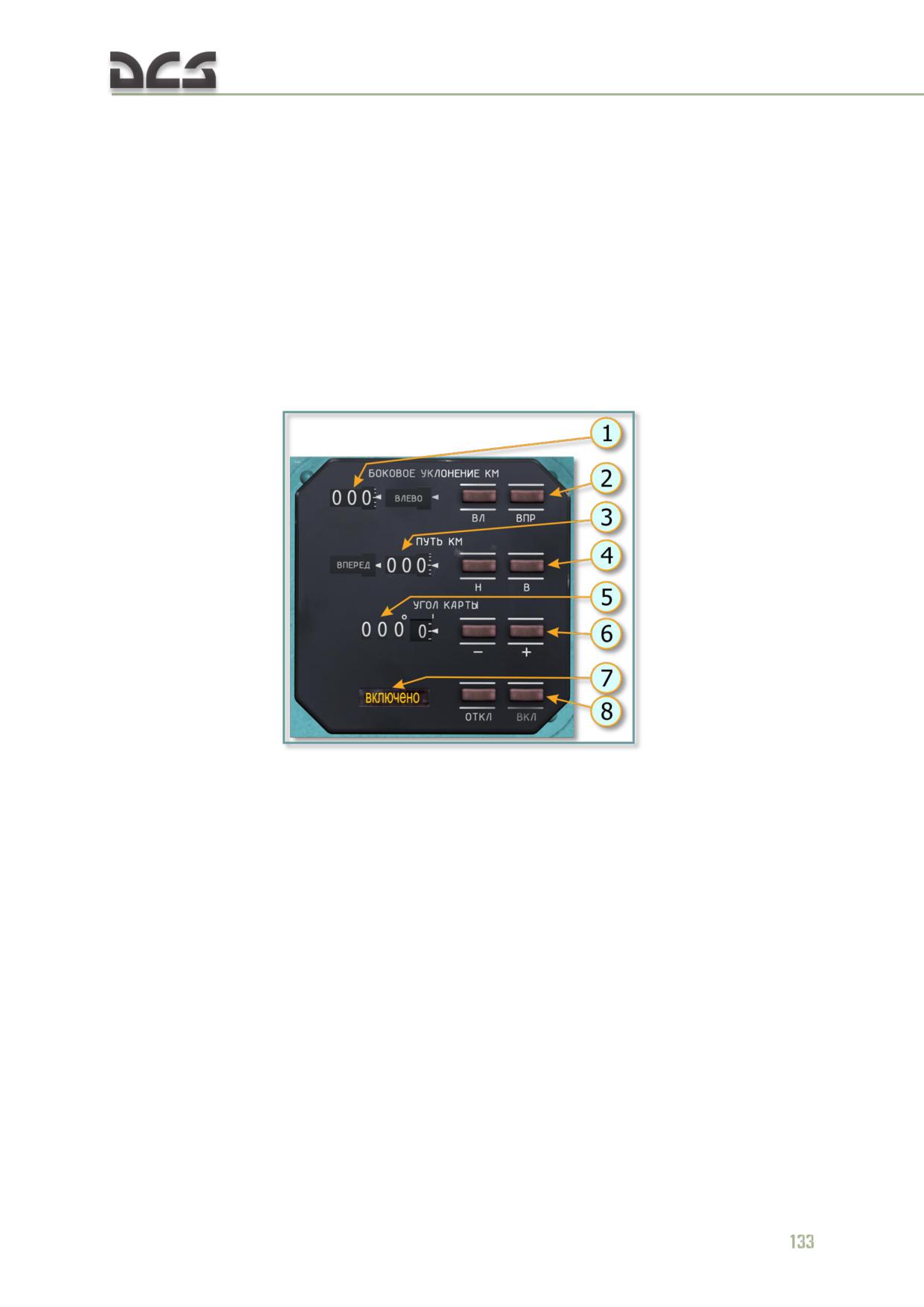
1. Ground speed window: displays ground speed
4. "Р-К" (TEST - OPERATE) knob: selects either
in kilometers per hour (KPH) within a range of 50
test or normal indicator operation mode. In TEST
- 400 KPH. At speed below 50 KPH, the window is
mode, the indicator shows 306 ±3.5 KPH and
blanked out;
15± 1° of drift;
2. Drift indicator needle: indicates the drift angle,
5. "С-М" (LAND - SEA) knob: used to select the
to the right or left, in degrees within a range of
characteristics of the surface the helicopter is
±45° on a scale graduated to 2°;
traveling over;
3. "П" (P) light: illuminates when the Doppler
system is operating in MEMORY mode;
DIGITAL DISPLAY UNIT: displays the distance the helicopter has flown from the starting
point and the lateral distance to the left or right of the course that the pilot enters on
the "УГОЛ КАРТЫ" (COURSE ANGLE) counter. The readout information is provided
by the Doppler computer.
Fig. 6.21. Digital display unit
1. "БОКОВОЕ УКЛОНЕНИЕ КМ" (LATERAL
4. "Н" (AFT), "В" (FWD) buttons: used to reset
DEVIATION) counter: drum-type counter with
the DISTANCE counter;
four wheels, right window displays direction of
5. "УГОЛ КАРТЫ" (COURSE ANGLE) counter:
deviation from course ("ВЛЕВО" (LEFT) or
drum-type counter with four wheels, displays the
"ВПРАВО" (RIGHT)); numerical counter displays
desired course in degrees (first three digits) and
the amount of lateral deviation in kilometers in
minutes (last two digits) in 6 minute steps;
200 m steps;
6. "-" and "+" buttons: used to set the counters
2. "ВЛ" (LEFT), "ВПР" (RIGHT) buttons: used to
to the desired course; counter does not rollover
reset the LATERAL DEVIATION counter;
between 0 and 360 degrees;
3. "ПУТЬ КМ" (DISTANCE) counter: drum-type
7. "ВКЛЮЧЕНО" (ON) light: indicates operation
counter with four wheels, dislpays the distance
of the unit;
the helicopter has flown from the starting point.
8. "ВКЛ" (ON) and "ОТКЛ" (OFF) buttons:
The left window displays the relative direction,
engage/disengage digital readout.
"ВПЕРЕД" (FORWARD) or "НАЗАД" AFT of the
starting point; numerical counters dislpay the
distance traveled in kilometers in 200 m steps;
DISS-15 OPERATION:
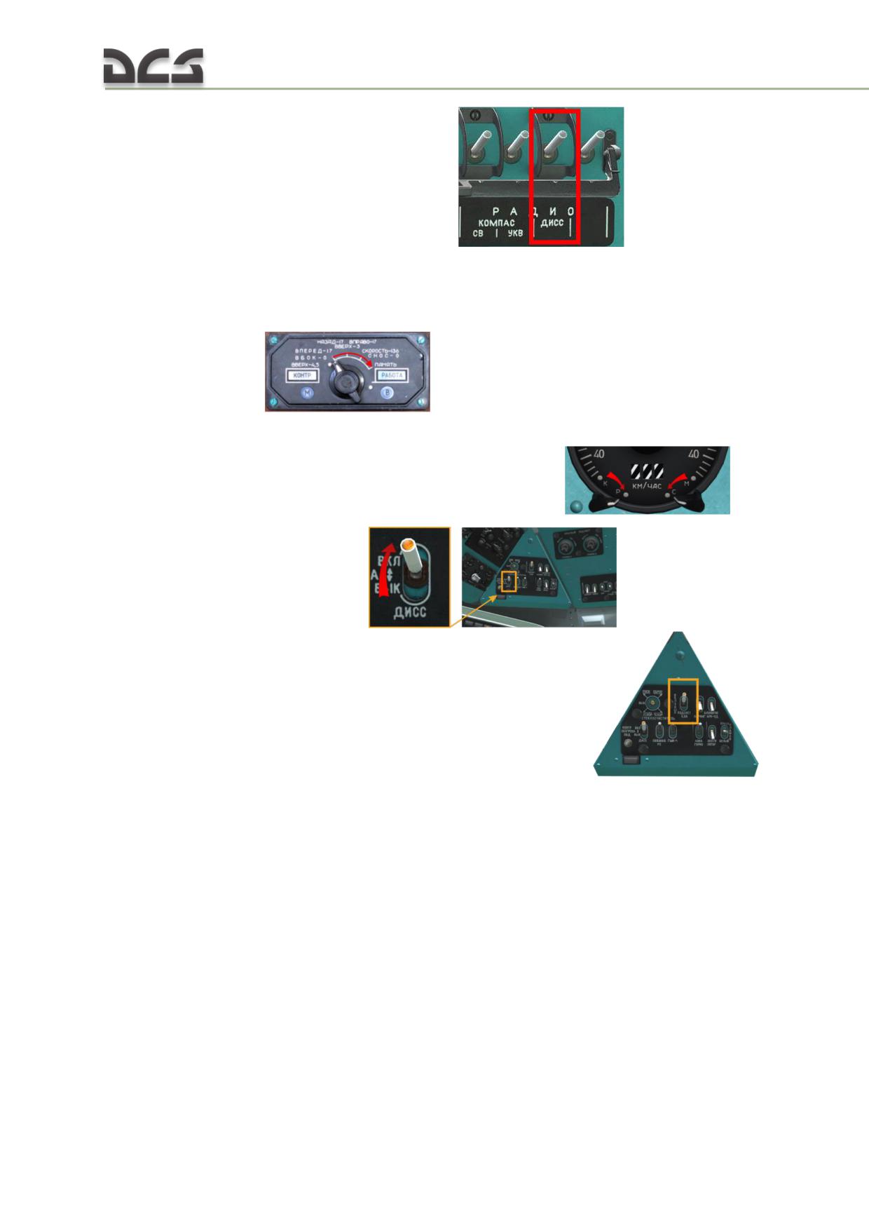
1. Close the DOPPLER (ДИСС) circuit breaker
After powering the circuits 27V and 115V 400Hz is necessary functionally check the
ДИСС-15 Doppler system proceeding as follows:
2. Set the selector switch on the Doppler monitor panel (behind of the co-pilot) to
MEMORY (ПАМЯТЬ)
3. Set the LAND-SEA
("C-M") and OPERATION-MONITORING
("K-P") selector
switches to LAND ("C") and OPERATION ("P"), respectively
4. Set the DOPP (ДИСС) switch
and, if necessary,
the DOPPLER LIGHT (ПОДСВЕТ ДИСС) switch to ON (BKЛ)
The TEST (KOHTP), "M" and "В" annunciators on the monitor panel and the "П"
annunciator on the ground speed and drift angle indicator, and the DOPP FAIL
(ДИСС ОТКАЗАЛ) annunciator on the RH instrument panel should come on.
5. Test the Doppler system for solving the test problems by successively setting the
selector switch on the Doppler monitor panel to 1, 2 and 3. The readings of the
hovering and low speed indicator should not differ by more than ±2.5 km/h and
±0.5 m/s respectively, from the values indicated on the monitor panel, and the
readings of the ground speed and drift angle indicator should be 136 ±3.5 km/h and
0 ± 1°, respectively.
6. Test the Doppler system in the SEA (MOPE) mode by setting the "C-M" (land-sea)
selector switch on the ground speed and drift angle indicator to "M"
134
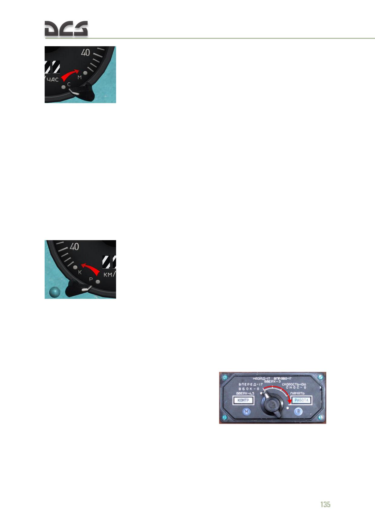
with the monitor panel selector switch set to SPEED - 136
(СКОРОСТЬ - 136), DRIFT - 0 (CHOC - 0). The ground speed should rise by 3
km/h. Leave the "C-M" selector switch either in "C" or "M" position depending on the
type of an anticipated flight - overterrain or over sea.
7. Test the coordinate indicator, for which purpose set the TRACK-KM (ПУТЬ KM),
XTK DISTANCE-КМ (БОКОВОЕ УКЛОНЕНИЕ-КМ), GRIVATION (УГОЛ КАРТЫ) digital
readouts to zero by operating the "H" (backward), "В" (forward), "ВЛ" (to left),
"ВПР" (to right), "-" and "+" keys. With the Doppler monitor panel selector switch
set to SPEED-136 (СКОРОСТЬ - 136), DRIFT - 0 (CHOC - 0), a ground speed
reading of 136 ± 3.5 km/h and a drift angle reading of 0 ± 1°, depress the ON (ВКЛ)
key on the coordinate indicator. With the Doppler system operating properly, the
FORWARD (ВПЕРЁД) digital readout of the coordinate indicator should display
11.3 km in 5 min and XTK DISTANCE-КМ - 0.
8. Check the computer for correct processing of the test problem introduced from the
ground speed and drift angle indicator by setting the "K-P" selector switch to "K"
. The ground speed reading should be 306 ±3.5 km/h, and the
drift angle reading should be to left 15±1°.
Check the doppler system for selection of the MEMORY mode by setting the monitor
panel selector switch to MEMORY (ПАМЯТЬ), and the ground speed reading should
change by not more than ±9 km/h and the drift angle reading by not more than ±3°.
The "П" annunciator on the ground speed and drift angle indicator should come on
simultaneously.
9. After completion of the above checks set the "К-P" selector switch to "P" and the
monitor panel selector switch to OPERAT (РАБОТА)
10. For using Digital display unit it necessary to set УГОЛ КАРТЫ (ROUTE (magnetic)
angle direction) as magnetic heading at map is required. Then the push "ВКЛ" (ON)
button for engage digital readout in begin route.
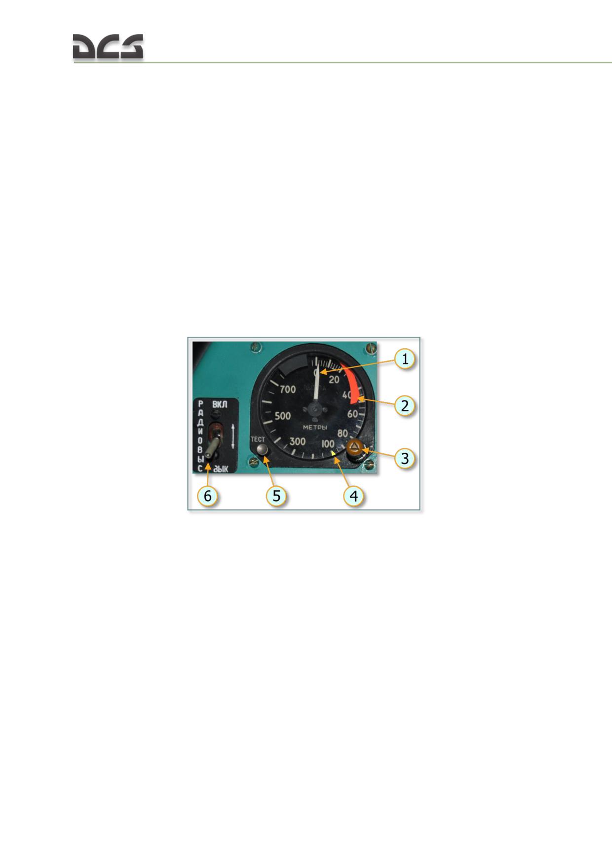
6.2.4. РВ-5 (RV-5) radar altimeter set
The radar altimeter set continuously indicates absolute altitude. The system is a
"look down" device which accurately measures the distance between the aircraft and
the highest terrain from 0 to 750 meters. The system accuracy is ±2 m at altitudes
up to 20 m and ±0.1 x N (where N equals altitude) at altitudes above 20 m.
RV-5 components:
The RV-5 radar altimeter set includes the following components:
transceiver
altimeter indicator on the pilot's (left) instrument panel
receiving and transmitting antennas installed on the bottom of the tail
boom
"РАДИОВЫСОТОМЕР" (RV-5) circuit breaker on the right circuit breaker
console
"РАДИОВЫСОТОМЕР ВКЛ. - ОТКЛ." (RADAR ALTIMETER) power switch on
the left instrument panel
Fig. 6.22. Radar altimeter indicator
1. Altimeter pointer
4. low altitude pointer shows low altitude setting
2. Altimeter fail flag
5. "ТЕСТ" (TEST) button to test the altimeter
3. SET ALTITUDE knob used to adjust ground-
6. "РАДИОВЫСОТОМЕР ВКЛ. - ОТКЛ." (RADAR
proximity warning setting. The SET ALTITUDE
ALTIMETER) power switch.
knob incorporates a yellow LOW ALT caution light
which illuminates when the helicopter descends
below preset altitude
The radar altimeter does not require additional adjustment or tuning for in-flight use
(except setting of ground proximity warning altitude).
Reliance on the radar altimeter is not recommended whenever:
flying in mountainous terrain where absolute altitude variations may
exceed the altimeter's limitations
roll or pitch angle exceeds 40°
136
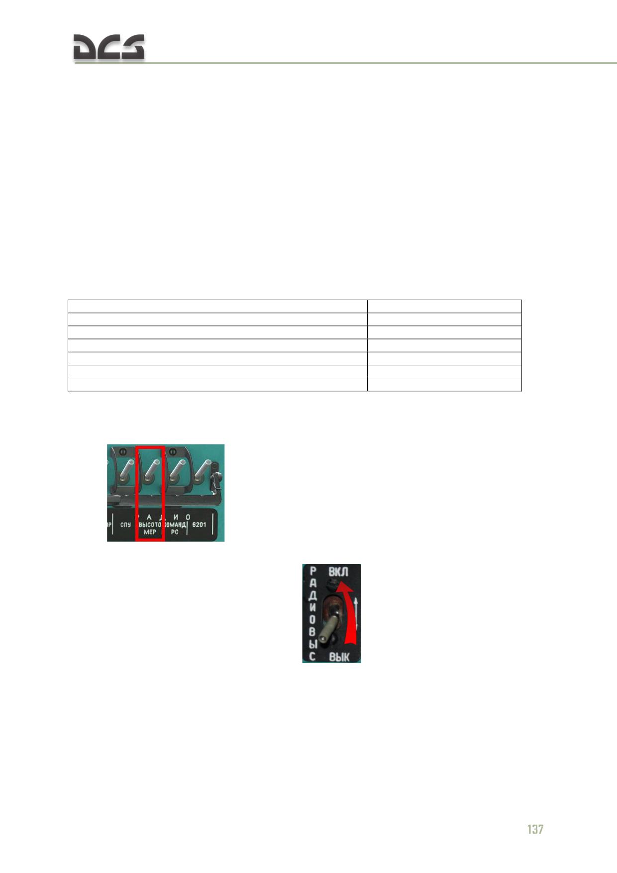
At roll angles greater than 20° the reading accuracy diminishes due to slant range
effects.
If helicopter altitude exceeds the altimeter's limitations or in case of failure, the red
fail flag appears along the scale on the right side of the indicator.
The LOW ALT caution light illuminates and an audio warning tone is heard when the
helicopter descends to the set ground proximity warning altitude.
The radar altimeter may indicate an erroneous reading if large sized cargo is
transported on external sling.
Switching off power to the radar altimeter will raise the power/failure warning flag on
the indicator and may leave the pointer indicating along the altitude scale.
The radar altimeter is powered with 27 VDC and 115 VAC 400 Hz.
RV-5 SPECIFICATIONS:
Frequency range
4200-4400 MHz
Altitude range
0-750 m
Modulation type
frequency
Audio warning duration
3-9 sec
Accuracy:
altitude: 0-20 m
±2 m
altitude:20-750 m
± 0.1 x N (N = altitude)
RV-5 OPERATION:
1. Turn on the "РАДИОВЫСОТОМЕР" (RV-5) circuit breaker on the right CB
panel
2. Set the "РАДИОВЫС. ВКЛ.- ВЫК." (RADAR ALTIMETER) switch on the left
instrument panel to the ON (UP) position
3. When turned on, the radar altimeter performs a self-test indicated by the
pointer turning to the blanked area at the top of the scale and returning to the
double-graduated area at the start of the scale within 1-2 min. When complete, the
test should result in the warning flag disappearing.
4. If the ground proximity warning altitude is set to at least 5 meters, descent
past the warning altitude setting will trigger a 3 - 9 second audio warning tone and
illuminate the LOW ALT caution light.
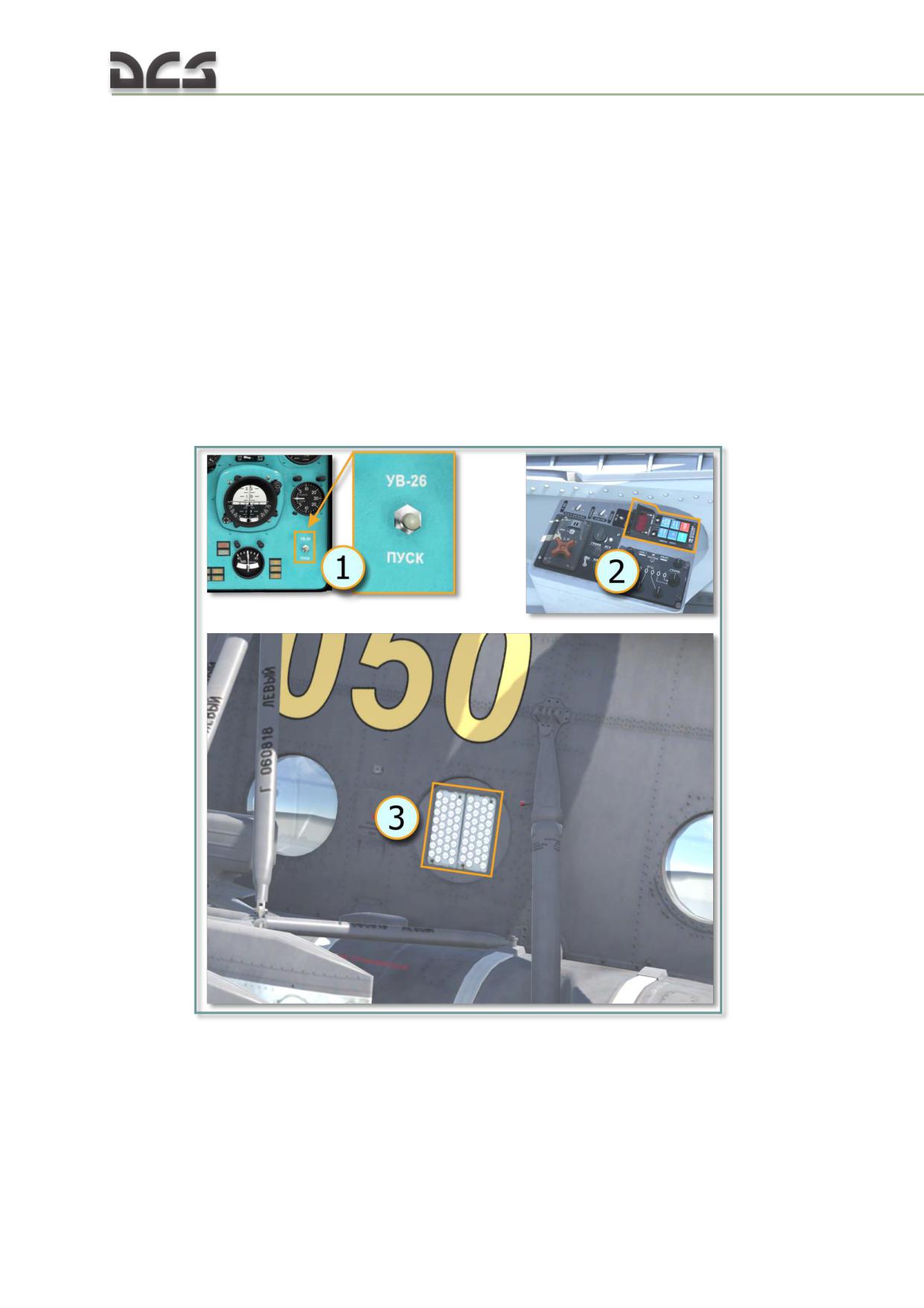
5. Press the "ТЕСТ" (TEST) button to test the indicator. Pressing the "ТЕСТ"
(TEST) button should turn the arrow around the scale to the banked out area at the
top.
6. Release the "ТЕСТ" (TEST) button to allow the arrow to return to its starting
position.
6.2.5. Special purpose radio systems (UV-26 EW countermeasures system)
The UV-26 EW countermeasures system (Flare Dispenser) are used as decoys
against heat-seeking missiles like the Igla (SA-16), FIM-92 Stinger, AIM-9
Sidewinder, R-60 (AA-8 Aphid), and R-73 (AA-11 Archer), etc.
Components
The UV-26 countermeasures system includes:
Fig. 6.23. The УВ-26 elements
(1) button for release flare on the Left Instrument Panel;
(2) UV-26 control panel, at Right Auxiliary Panel;
(3) four mounts (2x2) with Flares (at Left and Right side of fuselage). A
total of 4 mounts - 128 PPI-26 flare cartridges.
138
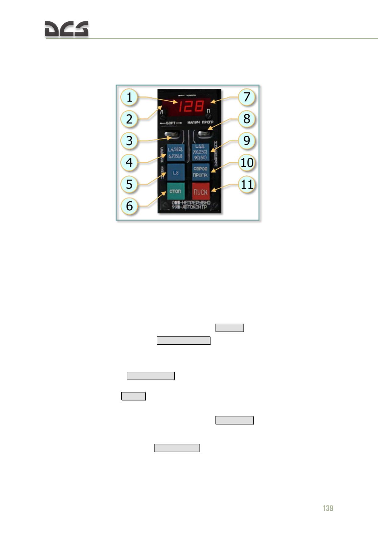
УВ-26 (UV-26) control panel
The UV-26 countermeasures control panel is located to the right of the overhead
panel and it is used to configure the release of infrared (IR) flare countermeasures.
Fig. 6.24. UV-26 control panel:
1. Program display. The digital read-out indicates the currently selected flare dispensing
parameters. When the "НАЛИЧ-ПРОГР" (REMAIN-PROGRAM) switch is in the "НАЛИЧ" (REMAIN)
position, the display shows the remaining quantity of flares (the Mi-8 can carry a maximum of 128).
When in the "ПРОГР" (PROGRAM) position, the first number indicates the "СЕРИЯ" (SEQUENCES)
setting, the second number indicates "ЗАЛП" (SALVO) setting, and the third number shows the
setting for "ИНТЕРВАЛ" (INTERVAL).
2. Dispenser side lamp - Indication that flares will be dispensed from the left dispenser.
3. "БОРТ" (LFT-RGT, left/right) release select switch. This is a three position switch that can be set
to the center position for release of flares from both sides; to the left for release of flares from the left
side or to the right for release of flares just from the right side. Depending on the selection, the
appropriate lamp(s) will be visible in the display field above.
[RAlt + ] ]
4. "СЕРИЯ" (SEQUENCUES) button
[RShift + Insert]
. Pressing this button cycles through the
number of flare sequences options. The number of sequences is equal to the number of times the
program will be run (except for 5 when the number of sequences is 12 and for 7 when the number of
sequences is 15). When the value is set to 0, flares will be dispensed continuously.
5. "ЗАЛП" (SALVO) button
[RCtrl + Insert]
. Press this button to cycle between the number of flares
to be released in a single program sequence. Values range 1 through
6. "СТОП" (STOP) button
[Delete]
. Stops the currently running program.
7. Dispenser side lamp - Indication that flares will be dispensed from the right dispenser.
8. "НАЛИЧИЕ - ПРОГР" (REMAIN - PROGRAM) switch
[RCTRL+ ] ]
. When set to "НАЛИЧИЕ"
(REMAIN), the display indicates the number of flares remaining; when set to "ПРОГР" (PROGRAM), it
shows the current flare program numeric code.
9. "ИНТЕРВАЛ" (INTERVAL) button
[RAlt + Insert]
. Pressing this button cycles between the time-
delay between flare release settings. The delay is in seconds and is equal to the displayed number
except for the cases of 7, 9 and 0, for which the intervals are 0.25, 0.5 and 0.125 seconds
respectively.
10. "СБРОС ПРОГР" (RESET) button
[RCtrl + Delete]
. This button resets the programmed
parameters to the default, "110".
11. "ПУСК" (DISPENSE) button
[Insert]
. Pressing this button executes the configured flare
dispersion program.
Example programs:
110: 1 sequence, dispense 1 flare, delay of 0.125s. Pressing "ПУСК" releases a
single flare from the selected side container (depending on the position of the
"БОРТ" (SIDE) switch). This is the default program.
622: 6 sequences, 2 flares in a sequence, 2 second interval. Flares will be dispensed
in pairs, one from each side or from one side only, again depending on the "БОРТ"
(SIDE) switch position.
529: 12 sequences, 2 flares in a sequence, interval of 0.5 s between releases.
140
7
SYSTEMS OF HELICOPTER
DIGITAL COMBAT SIMULATOR Mi-8МТV2
7. SYSTEMS OF HELICOPTER
7.1. Electrical Power Supply System
The helicopter power supply systems include primary and secondary power
sources as well as gound power sources, Fig. 7.1.
7.1.1. Primary Power Sources
The primary power source is AC electrical power system. This system includes
two 3-phase 208 VAC 400 Hz СГС-40ПУ (SGS- 40PU) generators. The primary
power source is rated at 80 kVA.
The No. 1 generator supplies power to:
The No.1 ВУ-6А (VU-6A) rectifier
A ТС310С04Б (TS310S04B) (208/36) power transformer
The main and tail rotor deice system.
The No. 2 generator supplies power to:
The No. 2 and No. 3 ВУ-6А (VU-6A) rectifiers
A ТС/1-2 (TS/1-2) (208/115) power transformer
The windshield deice system and the air inlet Particle Separator
System (PSS).
If one of the generators fails, power can be supplied to all systems, except the
main and tail rotor deice system, by switching the secondary power supply
sources (ТС310С04Б (TS310S04B) and ТС/1-2 (TS/1-2) transformers) to the
channel of the operational generator. Therewith, the No. 3 rectifier serves as a
backup and, in event of the No.1 generator fails, it connects to the No.1
generator channel. So that, if one of the generators fails, two generators
always operate.
If both generators fail, the components and systems required to safely
complete the flight are powered by the emergency power sources.
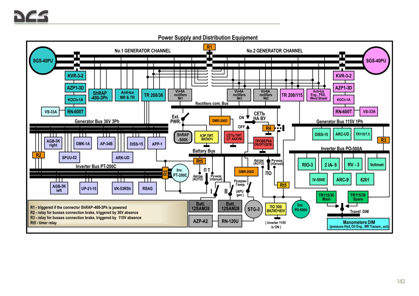
DIGITAL COMBAT SIMULATOR Mi-8МТV2
Fig. 7.1. Electrical Power Supply System Scheme
DIGITAL COMBAT SIMULATOR Mi-8МТV2
7.1.2. Secondary Power Sources
The helicopter electrical components are supplied AC and DC power by the following
single-channel power sources:
A Single-Phase 115 VAC 400 Hz System
A Single-Phase 36 VAC 400 Hz System
A 3-Phase 36 VAC 400 Hz System
A 27 VDC System
An Emergency Power Sources.
Single-Phase
115 VAC System
The single-phase 115 VAC 400 Hz system is powered by the No. 2 generator channel
through the ТС/1-2 (TS/1-2) power transformer. The transformer is rated at 2 kVA.
During normal operation, it supplies power to all installed components that require
115 VAC 400 Hz singlephase power. If the No. 2 generator fails, the ТС/1-2 (TS/1-2)
transformer is switched by a relay to receive power from the No. 1 generator
channel.
If both generators or the ТС/1-2 (TS/1-2) transformer fails, the 115 VAC components
and systems required for safe completion of the flight are powered by the ПО-500А
(PO-500A) backup inverter.
Single-Phase
36 VAC System
The single-phase 36 VAC 400 Hz system is powered by the single-phase 115 VAC
400 Hz Inverter Bus via the main and ТР 115/36 (TR115/36) standby power
transformers. The ТР 115/36 (TR115/36) power transformer supplies power to the
engine and drive system monitoring instruments.
3-Phase 36 VAC System
The 3-phase 36 VAC 400 Hz system is powered by the No. 1 generator channel
through the ТС310С04Б (TS310S04B) transformer. The transformer is rated at
1 kVA. During normal operation, the transformer provides power to all 3-phase 36
VAC components and systems. If the No.
1 generator fails, the ТС310С04Б
(TS310S04B) transformer is automatically switched to receive power from the No. 2
generator channel.
If both generators or the ТС310С04Б (TS310S04B) transformer fails, the 3-phase 36
VAC components and systems required for safe completion of the flight are powered
by the ПТ-200Ц (PT-200Ts) inverter.
27 VDC System
The 27 VDC system is powered by the AC generators through three ВУ-6А (VU-6A)
rectifiers, each rated at 6 kW. All three rectifiers are connected in parallel to a
common bus. The Rectifier Bus is linked to the Battery Bus through a ДМР-200Д
(DMR-200D) reverse current relay.
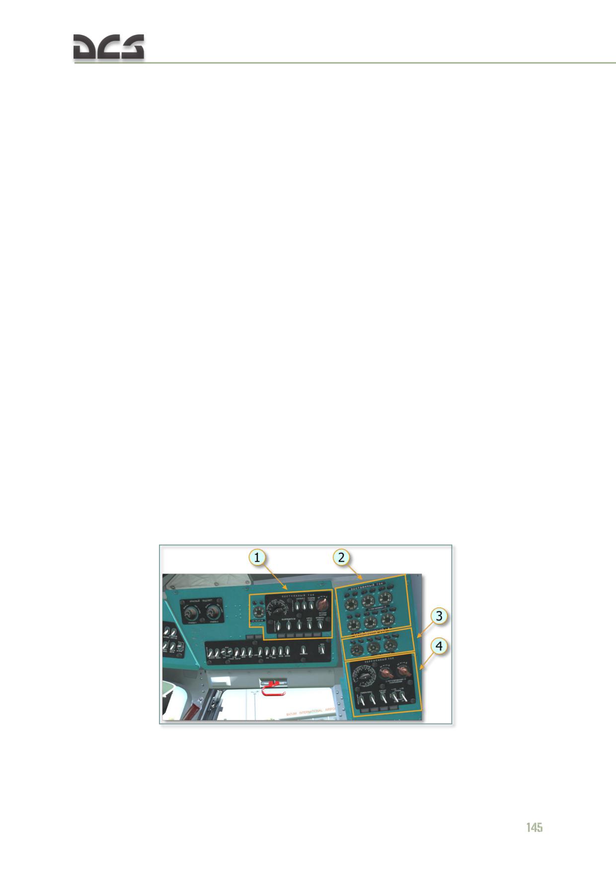
All 27 VDC components and systems can be powered by two of the rectifiers. The
No. 3 ВУ-6А (VU-6A) rectifier is connected to the No. 2 rectifier channel and serves
as a backup. If the No. 2 generator fails, the No. 3 rectifier switches automatically to
the No. 1 generator channel and along with the No. 1 ВУ-6А (VU-6A) rectifier powers
all 27 VDC components.
If both generators fail, or if there is a fault in the rectifier circuits, the flight essential
27 VDC components are powered by the emergency power sources, as two 12САМ-
28 (12SAM-28) batteries and the АИ-9В (AI-9V) engine СТГ-3 (STG-3) starter-
generator.
THE HELICOPTER EMERGENCY POWER SOURCES include:
two 12САМ-28 (12SAM-28) batteries
the ПО-500А (PО-500А) inverter
the ПТ-200Ц (PT-200Ts) inverter
the АИ-9В (AI-9V) engine СТГ-3 (STG-3) starter-generator.
Two batteries and the ПО-500А (PО-500А) and ПТ-200Ц (PT-200Ts) inverters serve
for safe completion of the helicopter flight. Emergency completion of the flight is
possible only when the batteries and the АИ-9В (AI-9V) engine СТГ-3 (STG-3)
starter-generator operate simultaneously. For this purpose, the starter-generator
should operate in a generator mode in 30 min.
Therewith, the АИ-9В (AI-9V) engine СТГ-3 (STG-3) starter-generator and ПО-500А
(PО-500А) and ПТ-200Ц (PT-200Ts) inventers can also be used for checking aircraft
systems on the ground under field conditions. The starter-generator is rated at 3 kW.
If it is used for ground testing, the DC components and systems must be checked
one at a time to prevent overloading.
7.1.3. Electrical Power Supply System Control
Electrical Power Supply System is controlled by the right side console in the cockpit,
Fig. 7.2.
Fig. 7.2. Location of the controls of electrical power supply system
1. DC Power Panel
3. AC system controls and indicators
2. DC system controls and indicators
4. AC Power Panel
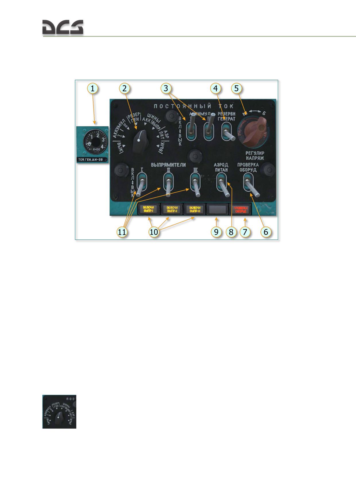
DC Power Control
DC power control (energizing, voltage control, load control) is exercised by DC Power
Panel, Fig. 7.3.
Fig. 7.3. Location of the controls of DC power
1. АИ-9В (AI-9V) generator ammeter (during
6. ПРОВЕРКА ОБОРУДОВАНИЯ (EQUIPMENT
operating as starter-generator, current should
TEST) switch, for connecting starter-generator
not exceed 100 A)
to battery bus)
2. Rotary switch, for connecting DC power
7. Lamp indicating ПРОВЕРКА
sources to control devices
ОБОРУДОВАНИЯ (EQUIPMENT TEST) switch
3. (I, II) batteries switches
ВКЛ. (ON) position
4. Starter-generator switch (installed on the
8. External DC 27-29 V Power switch
АИ-9В (AI-9V) engine)
9. Lamp indicating ШРАП-500К (SHRAP-500K)
5. External resistance to (I, II, III) rectifiers
connection to the board
voltage control, not used in the game
10. Lamp indicating disconnecting (I, II, III)
rectifiers from rectifiers battery bus when AC
generators operating
11. (I, II, III) rectifiers switches
The rectifiers and batteries load is controlled by ammeter indications. Each DC power
potential is controlled by DC voltmeter indications. The DC voltmeter and ammeter
are located on the right side console (Fig. 7.2, 2). Each DC power potential is
controlled by connecting the DC voltmeter to this DC power by the rotary switch
146
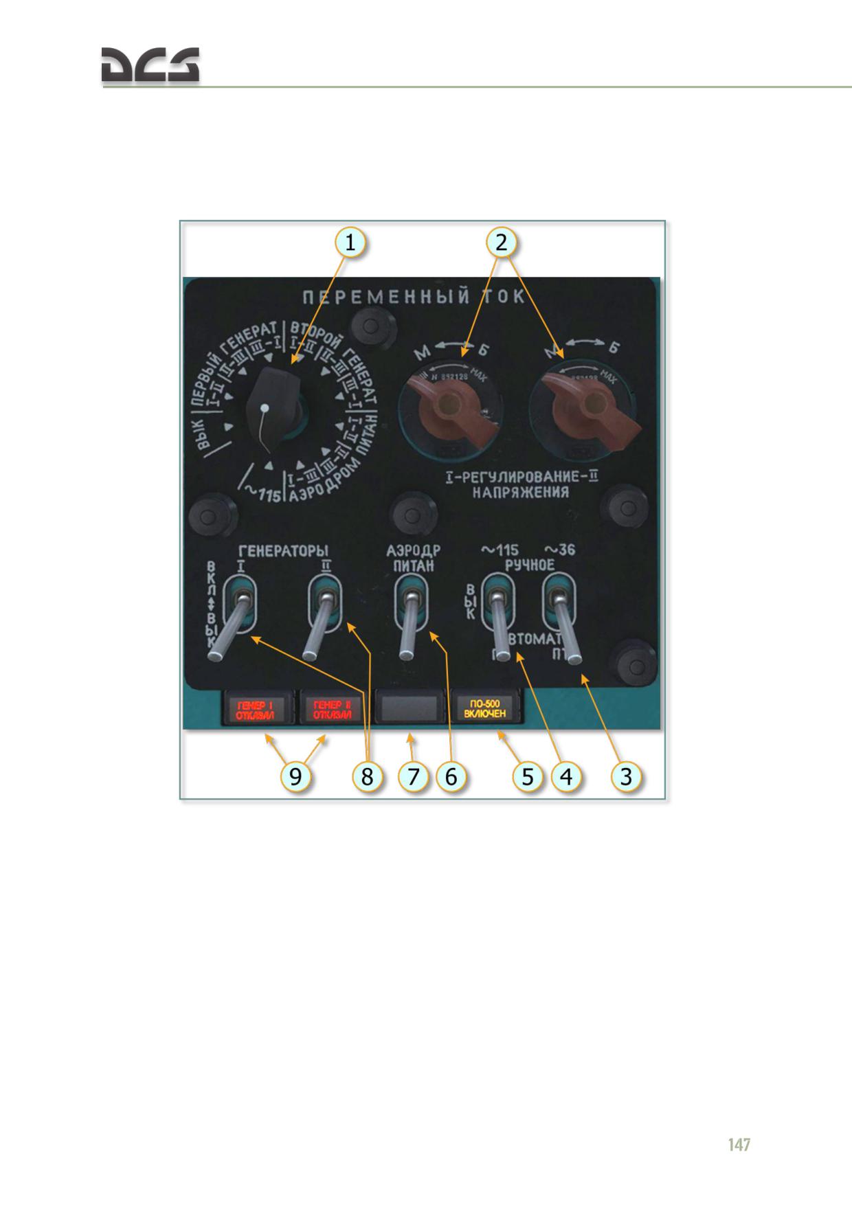
AC Power Control
AC power control (energizing, voltage control, load control) is exercised by AC Power
Panel, Fig. 7.4.
Fig. 7.4. Location of the controls of AC power
1. Rotary switch, for connecting AC power
5. Lamp indicating single-phase 115 VAC
sources to control devices
inverter operation
2. External resistance to (I, II) AC generators
6. External 208 VAC Power switch
voltage control, not used in the game
7. Lamp indicating ШРАП-400-3Ф (SHRAP-
3. 36 VAC ПТ (PT) Inverter switch. Three
400-3F) connection to the board
position switch, РУЧНОЕ (MANUAL) (up),
8. (I, II) AC generators switches
ВЫКЛ (OFF) (center), and АВТОМАТ (AUTO)
9. Lamp indicating (I, II) AC generators failure
(down).
4. 115 VAC ПO (PO) Inverter switch. Three
position switch, РУЧНОЕ (MANUAL) (up),
ВЫКЛ (OFF) (center), and АВТОМАТ (AUTO)
(down).
The rectifiers load is controlled by ammeter indications. Each AC power potential is
controlled by AC voltmeter indications. The AC voltmeter and ammeter are located
on the right side console (Fig. 7.2, 3), Each AC power potential is controlled by
connecting the AC voltmeter to this AC power by the rotary switch
7.1.4. Normal operation
Flight preparation and flight operation electric equipment procedures are set forth in
the section 9.1.
7.1.5. Failures
INDICATIONS:
the РИ-65 (RI-65) voice recorder message: "Отказал первый генератор"
(“The first generator failure”)
("Отказал второй генератор")
(“The
second generator failure”);
the ГЕНЕРАТОР I ОТКАЗАЛ (I GENERATOR FAILURE) (ГЕНЕРАТОР II
ОТКАЗАЛ) (II GENERATOR FAILURE) indicator lamp on the AC Power
Panel comes on;
Failed generator ammeter indicator goes to zero
After setting voltage control switch to the position of failed generator,
voltmeter indicator goes to zero.
CREW PROCEDURE:
Set failed generator ГЕНЕРАТОРЫ I (II) (GENERATORS I (II)) switch to
the ВЫК. (OFF) position;
Turn the main and tail rotor deice system off. For this purpose, on the
Deice System panel of the left side console:
o In case of flight operation with manually energized Deice System,
make sure that the ДВИГ. ПЗУ ЛЕВ. (ENGINE DUST PROTECTION
DEVICE LEFT) switch set to the ВКЛ. (ON) position, ДВИГ. ПЗУ ПРАВ.
(ENGINE DUST PROTECTION DEVICE RIGHT), СТЕКОЛ
(WINDSHIELD) switches set to the РУЧНОЕ (MANUAL) position. Then
set the ОБЩЕЕ РУЧН.-АВТОМ. (GENERAL MANUAL-AUTO) switch to
the АВТОМ. (AUTO) position and press the ВЫК. (OFF) button.
o In case of flight operation with automatically energized Deice System,
make sure that the ОБЩЕЕ РУЧН.-АВТОМ. (GENERAL MANUAL-
AUTO) switch set to the АВТОМ. (AUTO) position and the ДВИГ. ПЗУ
ЛЕВ. (ENGINE DUST PROTECTION DEVICE LEFT) switch set to the
ВКЛ. (ON) position. Then set ДВИГ. ПЗУ ПРАВ. (ENGINE DUST
PROTECTION DEVICE RIGHT), СТЕКОЛ (WINDSHIELD) switches to
the РУЧНОЕ (MANUAL) positions and press the ВЫК. (OFF) button.
Decide about further mission completion.
148
NOTE. After one generator failing, another operating generator fully supplies power to all helicopter
electrical components except for the main and tail rotors deice system.
BOTH AC GENERATORS FAILURE
INDICATIONS:
The РИ-65 (RI-65) voice recorder message: "Отказал первый генератор"
(“The first generator failure”), "Отказал второй генератор" (“The second
generator failure”);
The ГЕНЕРАТОР I ОТКАЗАЛ (I GENERATOR FAILURE), ГЕНЕРАТОР II
ОТКАЗАЛ (II GENERATOR FAILURE) indicator lamps on the AC Power
Panel come on;
Both generator ammeter indicators go to zero
After setting voltage control switch to the ПЕРВЫЙ ГЕНЕРАТОР (I
GENERATOR), ВТОРОЙ ГЕНЕРАТОР (II GENERATOR) positions voltmeter
indicators go to zero.
Failure of both generators results in automatically connecting of power to the battery
bus. The following flight essential equipment and systems will receive power:
The АИ-9В (AI-9V) Engine
The ПО-500 (PO-500) and ПТ-200Ц (PT-200Ts) Inverters
ЭМИ-ЗРИ (EMI-3RI) and ЭМИ-3РВИ (EMI-3RVI) Three-pointer indicators
The rotor pitch indicator
The 2ИА-6 (2IA-6) engine gauge and РТ12-6-20 (RT12-6-20) engine
temperature limiters
The ИВ-500Е (IV-500E) engine vibration monitors
The ИР-117 (IR-117) mode indicator
The main and backup hydraulic systems
The ГА-19 (GA-19) magnet crane in the engine control system
The left pitot tube heater
The fire protection system
Cockpit dome lights and group 2 red lighting
Cargo cabin lighting
The navigation lights
The copilot’s ФПП-7 (FPP-7) search/landing light
МСЛ-3 (MSL-3) anticollision light
The АРК-9 (ARK-9) ADF set and the Р-860 (R-860) radio set
The СПУ-7 (SPU-7) interphone system
The pilot’s attitude indicator АГБ-ЗК (AGB-3K)
Radar altimeter РВ-5 (RV-5)
Magnetic recording system МС-61 (MS-61)
Equipment САРПП-12ДМ (SARPP-12DM)
The external cargo hook ДГ-64 (DG-64)
The external store emergency jettison circuits
The pilot’s windshield wiper
The fuel pumps
The fuel valve
The fuel system fire valves
The engine inlet anti-ice system (bleed air)
The РИО-3 (RIO-3) ice formation warning sensor
The ЭКСР-46 (EKSR-46) signal flares
ЛПГ-150М (LPG-150M) winch (rescue hoist)
The СПУУ-52-1 (SPUU-52) tail rotor pitch limit control panel
РИ-65 (RI-65) voice data equipment
The ЭМТ-2М (EMT-2M) mag brakes
The ГА-192 (GA-192) collective clutch release valve solenoid.
CREW PROCEDURE:
Set ГЕНЕРАТОРЫ I, II (GENERATORS I, II) switches to the ВЫК. (OFF)
position;
Turn the main and tail rotor deice system off. For this purpose, on the
Deice System panel of the left side console:
o In case of flight operation with manually energized Deice System,
make sure that the ДВИГ. ПЗУ ЛЕВ. (ENGINE DUST PROTECTION
DEVICE LEFT) switch set to the ВКЛ. (ON) position, the ДВИГ. ПЗУ
ПРАВ. (ENGINE DUST PROTECTION DEVICE RIGHT) switch set to the
РУЧНОЕ (MANUAL) position. Then set ОБЩЕЕ РУЧН.-АВТОМ.
(GENERAL MANUAL-AUTO), СТЕКОЛ (WINDSHIELD) switches to the
АВТОМ. (AUTO) positions and press the ВЫК. (OFF) button.
o In case of flight operation with automatically energized Deice System,
make sure that ОБЩЕЕ РУЧН.-АВТОМ. (GENERAL MANUAL-AUTO),
СТЕКОЛ (WINDSHIELD) switches set to the АВТОМ. (AUTO) position
and the ДВИГ. ПЗУ ЛЕВ. (ENGINE DUST PROTECTION DEVICE LEFT)
switch set to the ВКЛ. (ON) position. Then set the ДВИГ. ПЗУ ПРАВ.
(ENGINE DUST PROTECTION DEVICE RIGHT) switch to the РУЧНОЕ
(MANUAL) position and press the ВЫК. (OFF) button.
Start the АИ-9В (AI-9V) engine, see section …
After the engine starting, set the РЕЗЕРВН. ГЕНЕРАТ. (STARTER-
GENERATOR) switch to the ВКЛ. (ON) position. Set the rotary switch on
the DC Power control to the РЕЗЕР. ГЕН. (STARTER-GENERATOR)
position. Check the generator potential by the voltmeter; the potential
should be within 27-29 V. Check the generator load by the ammeter, the
load should not exceed 100 A. The АИ-9В (AI-9V) Engine operating time
in the "Генератор" (GENERATOR) mode is up to 30 min
During specified time, Captain should decide about mission termination
and returning to the departure aerodrome or landing on the alternate
aerodrome.
NOTE. If all set above electrical components are supplied power only by batteries, their capacity will
be sufficient for 6-7 min flight.
7.2. Fuel System
Fuel system allocates appropriate quantity of fuel onboard and ensures uninterrupted
fuel feeding of main engines, auxiliary power unit and kerosene-combustion heater in
150