ROTORCRAFT FLYING HANDBOOK (2000) - page 3
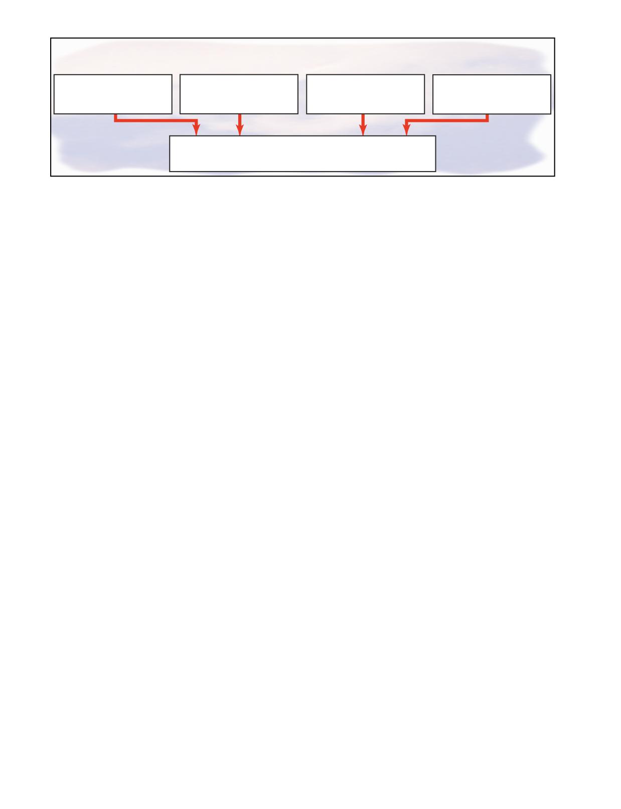
RISK ELEMENTS
Pilot
Aircraft
Environment
Operation
The pilot's fitness to fly must
The aircraft's performance,
Factors, such as weather,
The purpose of the flight is a
be evaluated including
limitations, equipment, and
airport conditions, and the
factor which influences the
competency in the aircraft,
airworthiness must be deter-
availability of air traffic control
pilot's decision on undertaking
currency, and flight experience.
mined.
services must be examined.
or continuing the flight.
Situation
To maintain situational awareness, an accurate perception must be
attained of how the pilot, aircraft, environment, and operation
combine to affect the flight.
Figure 14-3. When situationally aware, you have an overview of the total operation and are not fixated on one perceived signifi-
cant factor.
landing areas, and surrounding obstacles. Weather is
RISK MANAGEMENT
one element that can change drastically over time and
During each flight, decisions must be made regarding
distance. Imagine you are ferrying a helicopter cross
events that involve interactions between the four risk
country and encounter unexpected low clouds and rain
elements-the pilot in command, the aircraft, the envi-
in an area of rising terrain. Do you try to stay under
ronment, and the operation. The decision-making
them and “scud run,” or turn around, stay in the clear,
process involves an evaluation of each of these risk ele-
and obtain current weather information?
ments to achieve an accurate perception of the flight
situation. [Figure 14-3]
Operation-The interaction between you as the pilot,
your aircraft, and the environment is greatly influenced
One of the most important decisions that a pilot in com-
by the purpose of each flight operation. You must eval-
mand must make is the go/no-go decision. Evaluating
uate the three previous areas to decide on the desirabil-
each of these risk elements can help you decide
ity of undertaking or continuing the flight as planned. It
whether a flight should be conducted or continued. Let
is worth asking yourself why the flight is being made,
us evaluate the four risk elements and how they affect
how critical is it to maintain the schedule, and is the
our decision making regarding the following situations.
trip worth the risks? For instance, you are tasked to take
some technicians into rugged mountains for a routine
Pilot-As a pilot, you must continually make decisions
survey, and the weather is marginal. Would it be prefer-
about your own competency, condition of health, mental
able to wait for better conditions to ensure a safe flight?
and emotional state, level of fatigue, and many other
How would the priorities change if you were tasked to
variables. For example, you are called early in the morn-
search for cross-country skiers who had become lost in
ing to make a long flight. You have had only a few hours
deep snow and radioed for help?
of sleep, and are concerned that the congestion you feel
could be the onset of a cold. Are you safe to fly?
ASSESSING RISK
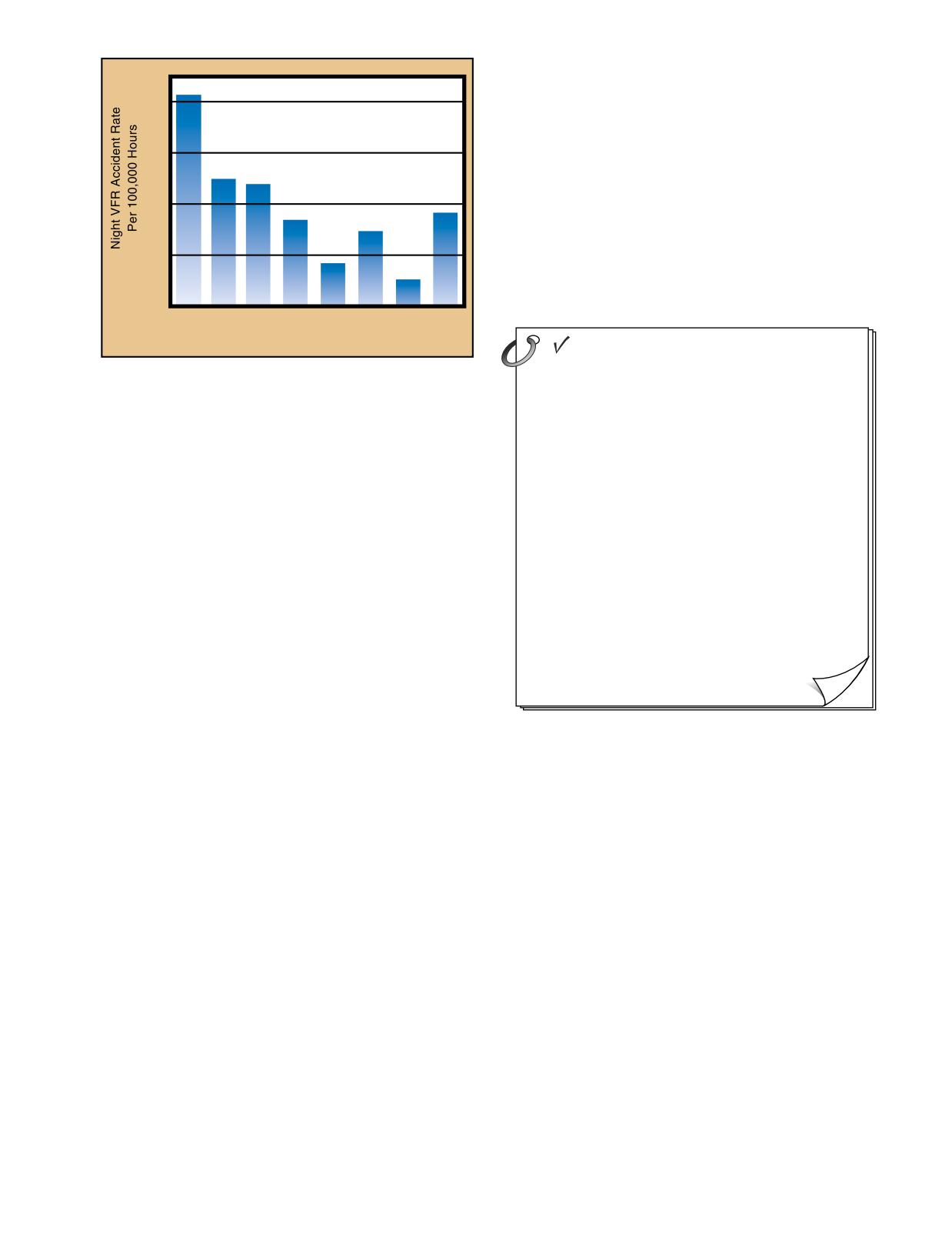
Examining NTSB reports and other accident research
Aircraft-You will frequently base decisions on your
can help you to assess risk more effectively. For exam-
evaluations of the aircraft, such as its powerplant, per-
ple, the accident rate decreases by nearly 50 percent once
formance, equipment, fuel state, or airworthiness. Picture
a pilot obtains 100 hours, and continues to decrease until
yourself in this situation: you are en route to an oil rig an
the 1,000 hour level. The data suggest that for the first
hour’s flight from shore, and you have just passed the
500 hours, pilots flying VFR at night should establish
shoreline. Then you notice the oil temperature at the high
higher personal limitations than are required by the reg-
end of the caution range. Should you continue out to sea,
ulations and, if applicable, apply instrument flying skills
or return to the nearest suitable heliport/airport?
in this environment. [Figure 14-4]
Environment-This encompasses many elements not
Studies also indicate the types of flight activities that
pilot or aircraft related. It can include such factors as
are most likely to result in the most serious accidents.
weather, air traffic control, navaids, terrain, takeoff and
The majority of fatal general aviation accident causes
fall under the categories of maneuvering flight,
Risk Elements-The four compo-
approaches, takeoff/initial climb, and weather. Delving
nents of a flight that make up the
deeper into accident statistics can provide some impor-
overall situation.
tant details that can help you to understand the risks
NTSB-National Transportation
involved with specific flying situations. For example,
Safety Board.
maneuvering flight is one of the largest single produc-
14-4
is used when preflighting an aircraft, a personal
checklist based on such factors as experience, cur-
40
rency, and comfort level can help determine if you are
prepared for a particular flight. Specifying when
refresher training should be accomplished and desig-
30
nating weather minimums, which may be higher than
those listed in Title 14 of the Code of Federal
20
Regulations (14 CFR) part 91, are elements that may
be included on a personal checklist. In addition to a
review of personal limitations, you should use the I’M
10
SAFE Checklist to further evaluate your fitness for
flight. [Figure 14-5]
<51
101
201
501 <1000 <2000 10,000 Total
Pilot's Total Time (Hours)
I'M SAFE CHECKLIST
Figure 14-4. Statistical data can identify operations that have
more risk.
Illness-Do I have any symptoms?
ers of fatal accidents. Fatal accidents, which occur
Medication-Have I been taking prescription or
during approach, often happen at night or in IFR condi-
over-the-counter drugs?
tions. Takeoff/initial climb accidents frequently are due
to the pilot’s lack of awareness of the effects of density
Stress-Am I under psychological pressure from
altitude on aircraft performance or other improper take-
the job? Worried about financial matters, health
problems, or family discord?
off planning resulting in loss of control during, or
shortly after takeoff. The majority of weather-related
Alcohol-Have I been drinking within 8 hours?
accidents occur after attempted VFR flight into IFR
Within 24 hours?
conditions.
Fatigue-Am I tired and not adequately rested?
FACTORS AFFECTING DECISION
Eating-Am I adequately nourished?
MAKING
It is important to point out the fact that being familiar
with the decision-making process does not ensure that
you will have the good judgment to be a safe pilot. The
Figure 14-5. Prior to flight, you should assess your fitness,
ability to make effective decisions as pilot in
just as you evaluate the aircraft’s airworthiness.
command depends on a number of factors. Some
circumstances, such as the time available to make a
decision, may be beyond your control. However, you
can learn to recognize those factors that can be man-
RECOGNIZING HAZARDOUS ATTITUDES
aged, and learn skills to improve decision-making
Being fit to fly depends on more than just your physi-
ability and judgment.
cal condition and recency of experience. For example,
attitude affects the quality of your decisions. Attitude
can be defined as a personal motivational predisposi-
PILOT SELF-ASSESSMENT
tion to respond to persons, situations, or events in a
The pilot in command of an aircraft is directly responsi-
given manner. Studies have identified five hazardous
ble for, and is the final authority as to, the operation of
attitudes that can interfere with your ability to make
that aircraft. In order to effectively exercise that respon-
sound decisions and exercise authority properly.
sibility and make effective decisions regarding the
[Figure 14-6]
outcome of a flight, you must have an understanding of
your limitations. Your performance during a flight is
Hazardous attitudes can lead to poor decision making
affected by many factors, such as health, recency of
and actions that involve unnecessary risk. You must
experience, knowledge, skill level, and attitude.
examine your decisions carefully to ensure that your
choices have not been influenced by hazardous
Exercising good judgment begins prior to taking the
attitudes, and you must be familiar with positive alter-
controls of an aircraft. Often, pilots thoroughly check
natives to counteract the hazardous attitudes. These
their aircraft to determine airworthiness, yet do not
substitute attitudes are referred to as antidotes. During
evaluate their own fitness for flight. Just as a checklist
a flight operation, it is important to be able to recognize
14-5
THE FIVE HAZARDOUS ATTITUDES
1. Anti-Authority:
This attitude is found in people who do not like anyone telling them what to do. In a sense, they
"Don't tell me."
are saying, "No one can tell me what to do." They may be resentful of having someone tell them
what to do, or may regard rules, regulations, and procedures as silly or unnecessary. However, it
is always your prerogative to question authority if you feel it is in error.
2. Impulsivity:
This is the attitude of people who frequently feel the need to do something, anything, immediately.
"Do it quickly."
They do not stop to think about what they are about to do; they do not select the best alternative,
and they do the first thing that comes to mind.
3. Invulnerability:
Many people feel that accidents happen to others, but never to them. They know accidents can
"It won't happen to me."
happen, and they know that anyone can be affected. They never really feel or believe that they will
be personally involved. Pilots who think this way are more likely to take chances and increase risk.
4. Macho:
Pilots who are always trying to prove that they are better than anyone else are thinking, "I can do it
"I can do it."
-I'll show them." Pilots with this type of attitude will try to prove themselves by taking risks in order
to impress others. While this pattern is thought to be a male characteristic, women are equally
susceptible.
5. Resignation:
Pilots who think, "What's the use?" do not see themselves as being able to make a great deal of
"What's the use?"
difference in what happens to them. When things go well, the pilot is apt to think that it is good luck.
When things go badly, the pilot may feel that someone is out to get me, or attribute it to bad luck.
The pilot will leave the action to others, for better or worse. Sometimes, such pilots will even go
along with unreasonable requests just to be a "nice guy."
Figure 14-6. You should examine your decisions carefully to ensure that your choices have not been influenced by a hazardous
attitude.
a hazardous attitude, correctly label the thought, and
HAZARDOUS ATTITUDES
ANTIDOTES
then recall its antidote. [Figure 14-7]
Macho-Brenda often brags to her
Taking
friends about her skills as a pilot and
chances is
STRESS MANAGEMENT
wants to impress them with her abilities.
foolish.
Everyone is stressed to some degree all the time. A cer-
During her third solo flight she decides to
tain amount of stress is good since it keeps a person
take a friend for a helicopter ride.
alert and prevents complacency. However, effects of
Anti-authority-In the air she thinks "It's
Follow the
stress are cumulative and, if not coped with adequately,
great to be up here without an instructor
rules. They are
they eventually add up to an intolerable burden.
usually right.
criticizing everything I do. His do-it-by-the-
Performance generally increases with the onset of
book attitude takes all of the fun out of
flying."
stress, peaks, and then begins to fall off rapidly as stress
levels exceed a person’s ability to cope. The ability to
Invulnerability-As she nears her friends
It could
make effective decisions during flight can be impaired
farm, she remembers that it is about eight
happen to me.
miles from the closest airport. She thinks,
by stress. Factors, referred to as stressors, can increase
"I'll land in the pasture behind the barn at
a pilot’s risk of error in the cockpit. [Figure 14-8]
Sarah's farm. It won't be dangerous at
all... the pasture is fenced and mowed
and no animals are in the way. It's no
There are several techniques to help manage the accu-
more dangerous than landing at a
mulation of life stresses and prevent stress overload.
heliport."
For example, including relaxation time in a busy sched-
ule and maintaining a program of physical fitness can
Impulsivity-After a short look, Brenda
Not so fast.
initiates an approach to her friend's
Think first.
help reduce stress levels. Learning to manage time
pasture. Not realizing that she is landing
more effectively can help you avoid heavy pressures
with a tail wind, she makes a hard landing
imposed by getting behind schedule and not meeting
in the pasture and nearly hits the fence
deadlines. Take an assessment of yourself to determine
with the tail rotor before she gets the
helicopter stopped.
your capabilities and limitations and then set realistic
goals. In addition, avoiding stressful situations and
Resignation-A policeman pulls up to
I'm not
encounters can help you cope with stress.
investigate what he believes to be an
helpless. I can
emergency landing. As Brenda is walking
make a
from the helicopter, she is supprised that
difference.
USE OF RESOURCES
anyone observed her landing. Her first
To make informed decisions during flight operations,
thought is "if it weren't for my bad luck, this
policeman wouldn't have come along and
you must be aware of the resources found both inside
this would have been a great afternoon."
and outside the cockpit. Since useful tools and sources
of information may not always be readily apparent,
Figure 14-7. You must be able to identify hazardous attitudes
learning to recognize these resources is an essential
and apply the appropriate antidote when needed.
part of ADM training. Resources must not only be iden-
14-6
STRESSORS
Physical Stress-Conditions associated with the environment, such as temperature and
humidity extremes, noise, vibration, and lack of oxygen.
Physiological Stress-Physical conditions, such as fatigue, lack of physical fitness, sleep
loss, missed meals (leading to low blood sugar levels), and illness.
Psychological Stress-Social or emotional factors, such as a death in the family, a divorce, a
sick child, or a demotion at work. This type of stress may also be related to mental workload,
such as analyzing a problem, navigating an aircraft, or making decisions.
Figure 14-8. The three types of stressors that can affect a pilot’s performance.
tified, but you must develop the skills to evaluate
information in an irregular situation, especially if they
whether you have the time to use a particular resource
are familiar with flying. A strange smell or sound may
and the impact that its use will have upon the safety of
alert a passenger to a potential problem. As pilot in
flight. For example, the assistance of ATC may be very
command, you should brief passengers before the
useful if you are lost. However, in an emergency situa-
flight to make sure that they are comfortable voicing
tion when action needs be taken quickly, time may not
any concerns.
be available to contact ATC immediately.
EXTERNAL RESOURCES
INTERNAL RESOURCES
Possibly the greatest external resources during flight
Internal resources are found in the cockpit during
are air traffic controllers and flight service specialists.
flight. Since some of the most valuable internal
ATC can help decrease pilot workload by providing
resources are ingenuity, knowledge, and skill, you can
traffic advisories, radar vectors, and assistance in emer-
expand cockpit resources immensely by improving
gency situations. Flight service stations can provide
these capabilities. This can be accomplished by fre-
updates on weather, answer questions about airport
quently reviewing flight information publications, such
conditions, and may offer direction-finding assistance.
as the CFRs and the AIM, as well as by pursuing addi-
The services provided by ATC can be invaluable in
tional training.
enabling you to make informed in-flight decisions.
A thorough understanding of all the equipment and sys-
WORKLOAD MANAGEMENT
tems in the aircraft is necessary to fully utilize all
Effective workload management ensures that essential
resources. For example, advanced navigation and
operations are accomplished by planning, prioritizing,
autopilot systems are valuable resources. However, if
and sequencing tasks to avoid work overload. As
pilots do not fully understand how to use this equip-
experience is gained, you learn to recognize future
ment, or they rely on it so much that they become
workload requirements and can prepare for high
complacent, it can become a detriment to safe flight.
workload periods during times of low workload.
Reviewing the appropriate chart and setting radio fre-
Checklists are essential cockpit resources for verifying
quencies well in advance of when they are needed
that the aircraft instruments and systems are checked,
helps reduce workload as your flight nears the airport.
set, and operating properly, as well as ensuring that the
In addition, you should listen to ATIS, ASOS, or
proper procedures are performed if there is a system
AWOS, if available, and then monitor the tower fre-
malfunction or in-flight emergency. In addition, the
quency or CTAF to get a good idea of what traffic
FAA-approved rotorcraft flight manual, which is
conditions to expect. Checklists should be performed
required to be carried on board the aircraft, is essential
well in advance so there is time to focus on traffic and
for accurate flight planning and for resolving in-flight
ATC instructions. These procedures are especially
equipment malfunctions. Other valuable cockpit
important prior to entering a high-density traffic area,
resources include current aeronautical charts, and pub-
such as Class B airspace.
lications, such as the Airport/Facility Directory.
To manage workload, items should be prioritized. For
example, during any situation, and especially in an
Passengers can also be a valuable resource. Passengers
emergency, you should remember the phrase “aviate,
can help watch for traffic and may be able to provide
14-7
navigate, and communicate.” This means that the first
of the environmental conditions of the flight, such as
thing you should do is make sure the helicopter is under
spatial orientation of the helicopter, and its relation-
ship to terrain, traffic, weather, and airspace must be
maintained.
Pilot Capabilities
To maintain situational awareness, all of the skills
involved in aeronautical decision making are used. For
Margin
example, an accurate perception of your fitness can be
of Safety
achieved through self-assessment and recognition of
hazardous attitudes. A clear assessment of the status of
navigation equipment can be obtained through work-
Task
load management, and establishing a productive
Requirements
relationship with ATC can be accomplished by effec-
Time
tive resource use.
Preflight
Taxi
Takeoff
Cruise
Approach &
Taxi
Landing
OBSTACLES TO MAINTAINING SITUATIONAL
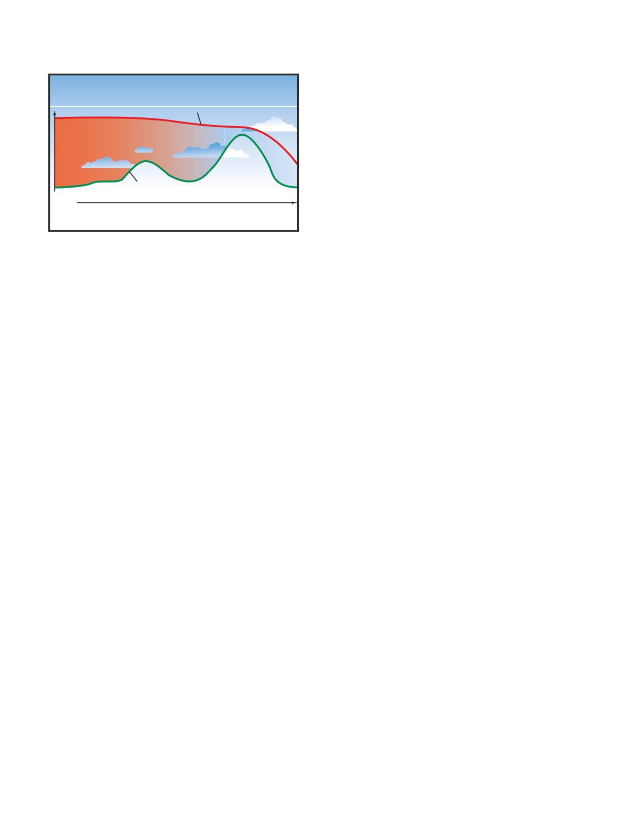
Figure 14-9. Accidents often occur when flying task require-
AWARENESS
ments exceed pilot capabilities. The difference between
Fatigue, stress, and work overload can cause you to fix-
these two factors is called the margin of safety. Note that in
this idealized example, the margin of safety is minimal during
ate on a single perceived important item rather than
the approach and landing. At this point, an emergency or dis-
maintaining an overall awareness of the flight situa-
traction could overtax pilot capabilities, causing an accident.
tion. A contributing factor in many accidents is a
distraction that diverts the pilot’s attention from moni-
toring the instruments or scanning outside the
control. Then begin flying to an acceptable landing
aircraft. Many cockpit distractions begin as a minor
area. Only after the first two items are assured, should
problem, such as a gauge that is not reading correctly,
you try to communicate with anyone.
but result in accidents as the pilot diverts attention to
the perceived problem and neglects to properly control
Another important part of managing workload is rec-
the aircraft.
ognizing a work overload situation. The first effect of
high workload is that you begin to work faster. As
Complacency presents another obstacle to maintaining
workload increases, attention cannot be devoted to sev-
situational awareness. When activities become routine,
eral tasks at one time, and you may begin to focus on
you may have a tendency to relax and not put as much
one item. When you become task saturated, there is no
effort into performance. Like fatigue, complacency
awareness of inputs from various sources, so decisions
reduces your effectiveness in the cockpit. However,
may be made on incomplete information, and the pos-
complacency is harder to recognize than fatigue, since
sibility of error increases. [Figure 14-9]
everything is perceived to be progressing smoothly. For
example, you have just dropped off another group of
When becoming overloaded, you should stop, think,
fire fighters for the fifth time that day. Without think-
slow down, and prioritize. It is important that you
ing, you hastily lift the helicopter off the ground, not
understand options that may be available to decrease
realizing that one of the skids is stuck between two
workload. For example, tasks, such as locating an item
rocks. The result is dynamic rollover and a destroyed
on a chart or setting a radio frequency, may be dele-
helicopter.
gated to another pilot or passenger, an autopilot, if
available, may be used, or ATC may be enlisted to
provide assistance.
OPERATIONAL PITFALLS
There are a number of classic behavioral traps into
SITUATIONAL AWARENESS
which pilots have been known to fall. Pilots, particu-
Situational awareness is the accurate perception of the
larly those with considerable experience, as a rule,
operational and environmental factors that affect the
always try to complete a flight as planned, please pas-
aircraft, pilot, and passengers during a specific period
sengers, and meet schedules. The basic drive to meet
of time. Maintaining situational awareness requires
or exceed goals can have an adverse effect on safety,
an understanding of the relative significance of these
and can impose an unrealistic assessment of piloting
factors and their future impact on the flight. When sit-
skills under stressful conditions. These tendencies ulti-
uationally aware, you have an overview of the total
mately may bring about practices that are dangerous
operation and are not fixated on one perceived signif-
and often illegal, and may lead to a mishap. You will
icant factor. Some of the elements inside the aircraft
develop awareness and learn to avoid many of these
to be considered are the status of aircraft systems, you
operational pitfalls through effective ADM training.
as the pilot, and passengers. In addition, an awareness
[Figure 14-10]
14-8
OPERATIONAL PITFALLS
Peer Pressure-Poor decision making may be based upon an emotional response to peers, rather than evaluating a situation
objectively.
Mind Set-A pilot displays mind set through an inability to recognize and cope with changes in a given situation.
Get-There-Itis-This disposition impairs pilot judgment through a fixation on the original goal or destination, combined with a
disregard for any alternative course of action.
Scud Running-This occurs when a pilot tries to maintain visual contact with the terrain at low altitudes while instrument
conditions exist.
Continuing Visual Flight Rules (VFR) into Instrument Conditions-Spatial disorientation or collision with ground/obstacles
may occur when a pilot continues VFR into instrument conditions. This can be even more dangerous if the pilot is not
instrument-rated or current.
Getting Behind the Aircraft-This pitfall can be caused by allowing events or the situation to control pilot actions. A constant
state of surprise at what happens next may be exhibited when the pilot is getting behind the aircraft.
Loss of Positional or Situational Awareness-In extreme cases, when a pilot gets behind the aircraft, a loss of positional or
situational awareness may result. The pilot may not know the aircraft's geographical location, or may be unable to recognize
deteriorating circumstances.
Operating Without Adequate Fuel Reserves-Ignoring minimum fuel reserve requirements is generally the result of
overconfidence, lack of flight planning, or disregarding applicable regulations.
Flying Outside the Envelope-The assumed high performance capability of a particular aircraft may cause a mistaken belief
that it can meet the demands imposed by a pilot's overestimated flying skills.
Neglect of Flight Planning, Preflight Inspections, and Checklists-A pilot may rely on short- and long-term memory,
regular flying skills, and familiar routes instead of established procedures and published checklists. This can be particularly true
of experienced pilots.
Figure 14-10. All experienced pilots have fallen prey to, or have been tempted by, one or more of these tendencies in their flying
careers.
14-9
14-10
autorotation. The first successful example of this type
January 9th, 1923, marked the first officially observed
of aircraft was the British Fairy Rotodyne, certificated
flight of an autogyro. The aircraft, designed by Juan de
to the Transport Category in 1958. During the 1960s
la Cierva, introduced rotor technology that made for-
and 1970s, the popularity of gyroplanes increased with
ward flight in a rotorcraft possible. Until that time,
the certification of the McCulloch J-2 and Umbaugh.
rotary-wing aircraft designers were stymied by the
The latter becoming the Air & Space 18A.
problem of a rolling moment that was encountered
when the aircraft began to move forward. This rolling
There are several aircraft under development using the
moment was the product of airflow over the rotor disc,
free spinning rotor to achieve rotary wing takeoff per-
causing an increase in lift of the advancing blade and
formance and fixed wing cruise speeds. The gyroplane
decrease in lift of the retreating blade. Cierva’s success-
offers inherent safety, simplicity of operation, and out-
ful design, the C.4, introduced the articulated rotor, on
standing short field point-to-point capability.
which the blades were hinged and allowed to flap. This
solution allowed the advancing blade to move upward,
decreasing angle of attack and lift, while the retreating
TYPES OF GYROPLANES
blade would swing downward, increasing angle of
Because the free spinning rotor does not require an
attack and lift. The result was balanced lift across the
antitorque device, a single rotor is the predominate
rotor disc regardless of airflow. This breakthrough was
configuration. Counter-rotating blades do not offer
instrumental in the success of the modern helicopter,
any particular advantage. The rotor system used in a
which was developed over 15 years later. (For more
gyroplane may have any number of blades, but the
information on dissymmetry of lift, refer to Chapter 3-
most popular are the two and three blade systems.
Aerodynamics of Flight.) On April 2, 1931, the Pitcairn
Propulsion for gyroplanes may be either tractor or
PCA-2 autogyro was granted Type Certificate No. 410
pusher, meaning the engine may be mounted on the
and became the first rotary wing aircraft to be certified
front and pull the aircraft, or in the rear, pushing it
in the United States. The term “autogyro” was used to
through the air. The powerplant itself may be either
describe this type of aircraft until the FAA later desig-
reciprocating or turbine. Early gyroplanes were
nated them “gyroplanes.”
often a derivative of tractor configured airplanes
with the rotor either replacing the wing or acting in
By definition, the gyroplane is an aircraft that achieves
conjunction with it. However, the pusher configura-
lift by a free spinning rotor. Several aircraft have used
tion is generally more maneuverable due to the
the free spinning rotor to attain performance not avail-
placement of the rudder in the propeller slipstream,
able in the pure helicopter. The “gyrodyne” is a hybrid
and also has the advantage of better visibility for the
rotorcraft that is capable of hovering and yet cruises in
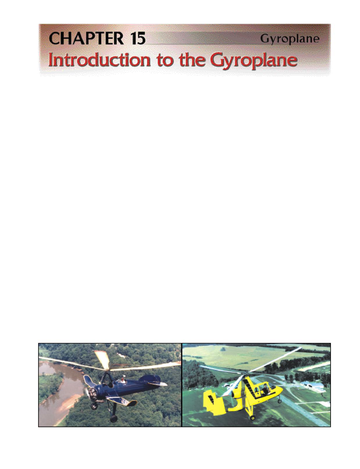
pilot. [Figure 15-1]
Figure 15-1. The gyroplane may have wings, be either tractor or pusher configured, and could be turbine or propeller powered.
Pictured are the Pitcairn PCA-2 Autogyro (left) and the Air & Space 18A gyroplane.
15-1
When direct control of the rotor head was perfected,
the welded tube structure, which has been in use for a
the jump takeoff gyroplane was developed. Under the
number of years.
proper conditions, these gyroplanes have the ability to
lift off vertically and transition to forward flight. Later
POWERPLANT
developments have included retaining the direct con-
The powerplant provides the thrust necessary for forward
trol rotor head and utilizing a wing to unload the rotor,
flight, and is independent of the rotor system while in
which results in increased forward speed.
flight. While on the ground, the engine may be used as
a source of power to prerotate the rotor system. Over
COMPONENTS
the many years of gyroplane development, a wide
Although gyroplanes are designed in a variety of config-
variety of engine types have been adapted to the gyro-
urations, for the most part the basic components are the
plane. Automotive, marine, ATV, and certificated
same. The minimum components required for a func-
aircraft engines have all been used in various
tional gyroplane are an airframe, a powerplant, a rotor
gyroplane designs. Certificated gyroplanes are
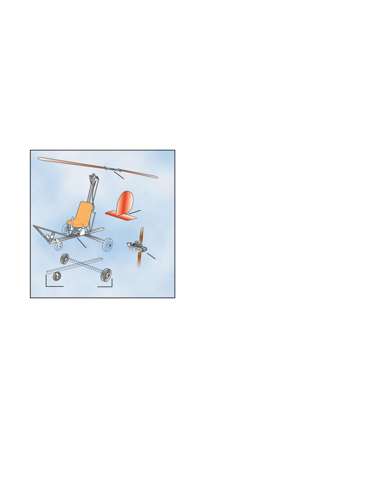
system, tail surfaces, and landing gear. [Figure 15-2] An
required to use FAA certificated engines. The cost of a
optional component is the wing, which is incorporated
new certificated aircraft engine is greater than the cost
into some designs for specific performance objectives.
of nearly any other new engine. This added cost is the
primary reason other types of engines are selected for
use in amateur built gyroplanes.
ROTOR SYSTEM
The rotor system provides lift and control for the gyro-
Rotor
plane. The fully articulated and semi-rigid teetering
rotor systems are the most common. These are
explained in-depth in Chapter 5-Main Rotor System.
The teeter blade with hub tilt control is most common
Tail
in homebuilt gyroplanes. This system may also employ
Surfaces
a collective control to change the pitch of the rotor
blades. With sufficient blade inertia and collective
pitch change, jump takeoffs can be accomplished.
Airframe
TAIL SURFACES
The tail surfaces provide stability and control in the pitch
Powerplant
and yaw axes. These tail surfaces are similar to an air-
plane empennage and may be comprised of a fin and
rudder, stabilizer and elevator. An aft mounted duct
Landing Gear
enclosing the propeller and rudder has also been used.
Many gyroplanes do not incorporate a horizontal tail
surface.
Figure 15-2. Gyroplanes typically consist of five major com-
ponents. A sixth, the wing, is utilized on some designs.
On some gyroplanes, especially those with an enclosed
cockpit, the yaw stability is marginal due to the large
AIRFRAME
fuselage side area located ahead of the center of grav-
The airframe provides the structure to which all other
ity. The additional vertical tail surface necessary to
components are attached. Airframes may be welded
compensate for this instability is difficult to achieve as
tube, sheet metal, composite, or simply tubes bolted
the confines of the rotor tilt and high landing pitch atti-
together. A combination of construction methods may
tude limits the available area. Some gyroplane designs
also be employed. The airframes with the greatest
incorporate multiple vertical stabilizers and rudders to
strength-to-weight ratios are a carbon fiber material or
add additional yaw stability.
Direct Control-The capacity for
Unload-To reduce the compo-
Prerotate-Spinning a gyroplane
the pilot to maneuver the aircraft
nent of weight supported by the
rotor to sufficient r.p.m. prior to
by tilting the rotor disc and, on
rotor system.
flight.
some gyroplanes, affect changes in
pitch to the rotor blades. These
equate to cyclic and collective con-
trol, which were not available in
earlier autogyros.
15-2
LANDING GEAR
of the aircraft. This will allow rotary wing takeoff
The landing gear provides the mobility while on the
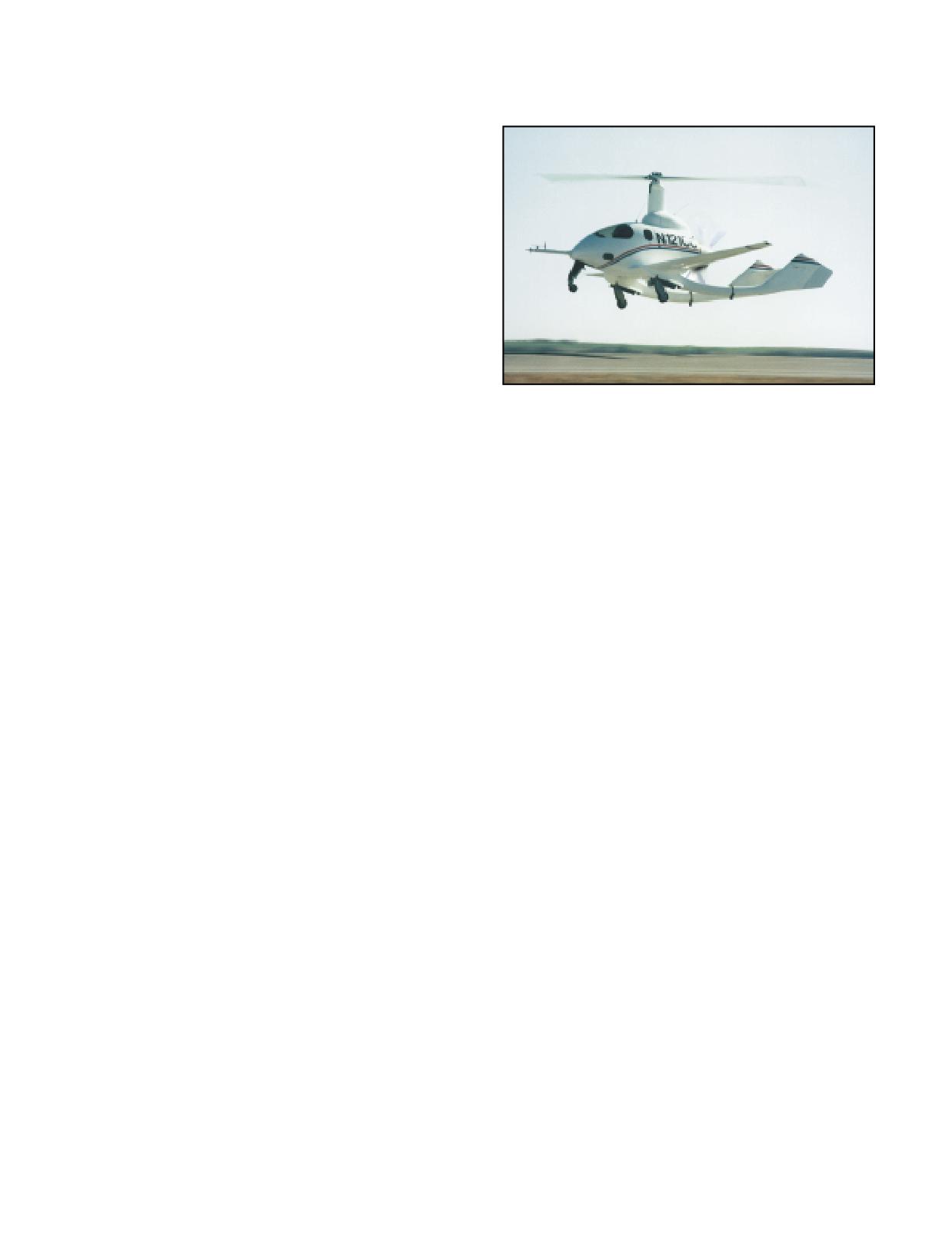
performance with fixed wing cruise speeds. [Figure
ground and may be either conventional or tricycle.
15-3]
Conventional gear consists of two main wheels, and one
under the tail. The tricycle configuration also uses two
mains, with the third wheel under the nose. Early auto-
gyros, and several models of gyroplanes, use conven-
tional gear, while most of the later gyroplanes
incorporate tricycle landing gear. As with fixed wing
aircraft, the gyroplane landing gear provides the ground
mobility not found in most helicopters.
WINGS
Wings may or may not comprise a component of the
gyroplane. When used, they provide increased per-
formance, increased storage capacity, and increased
stability. Gyroplanes are under development with
wings that are capable of almost completely unload-
Figure 15-3. The CarterCopter uses wings to enhance
ing the rotor system and carrying the entire weight
performance.
15-3
15-4
Helicopters and gyroplanes both achieve lift through
for a given flight condition. The other component is the
the use of airfoils, and, therefore, many of the basic
rotational airflow, which is the wind velocity across the
aerodynamic principles governing the production of lift
blades as they spin. This component varies signifi-
apply to both aircraft. These concepts are explained in
cantly based upon how far from the rotor hub it is
depth in Chapter 2-General Aerodynamics, and con-
measured. For example, consider a rotor disc that is 25
stitute the foundation for discussing the aerodynamics
feet in diameter operating at 300 r.p.m. At a point one
of a gyroplane.
foot outboard from the rotor hub, the blades are travel-
ing in a circle with a circumference of 6.3 feet. This
AUTOROTATION
equates to 31.4 feet per second (f.p.s.), or a rotational
A fundamental difference between helicopters and
blade speed of 21 m.p.h. At the blade tips, the circum-
gyroplanes is that in powered flight, a gyroplane rotor
ference of the circle increases to 78.5 feet. At the same
system operates in autorotation. This means the rotor
operating speed of 300 r.p.m., this creates a blade tip
spins freely as a result of air flowing up through the
blades, rather than using engine power to turn the
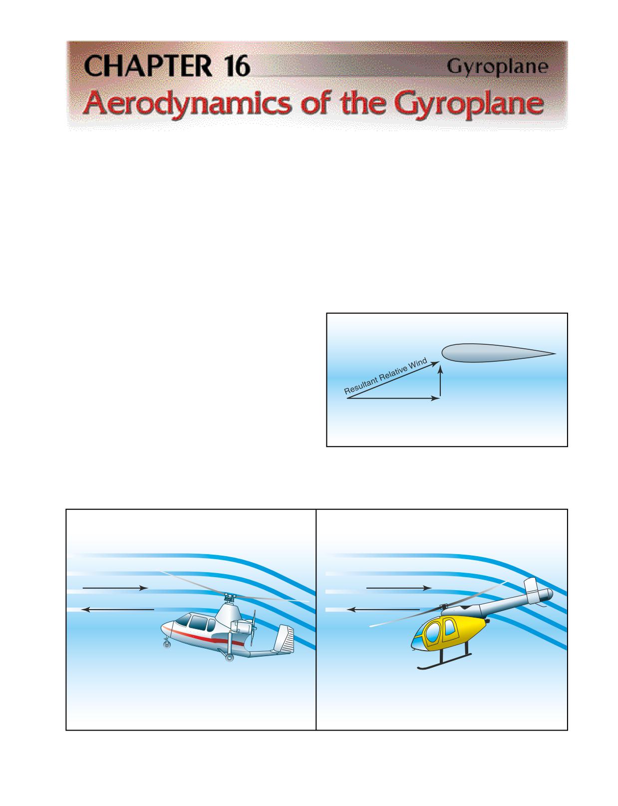
blades and draw air from above. [Figure 16-1] Forces
are created during autorotation that keep the rotor
blades turning, as well as creating lift to keep the air-
craft aloft. Aerodynamically, the rotor system of a
Upward
gyroplane in normal flight operates like a helicopter
Airflow
rotor during an engine-out forward autorotative
descent.
Wind due to Blade Rotation
VERTICAL AUTOROTATION
During a vertical autorotation, two basic components
contribute to the relative wind striking the rotor blades.
Figure 16-2. In a vertical autorotation, the wind from the
[Figure 16-2] One component, the upward flow of air
rotation of the blade combines with the upward airflow to
through the rotor system, remains relatively constant
produce the resultant relative wind striking the airfoil.
Relative Wind
Relative Wind
Direction of Flight
Direction of Flight
Figure 16-1. Airflow through the rotor system on a gyroplane is reversed from that on a powered helicopter. This airflow is the
medium through which power is transferred from the gyroplane engine to the rotor system to keep it rotating.
16-1
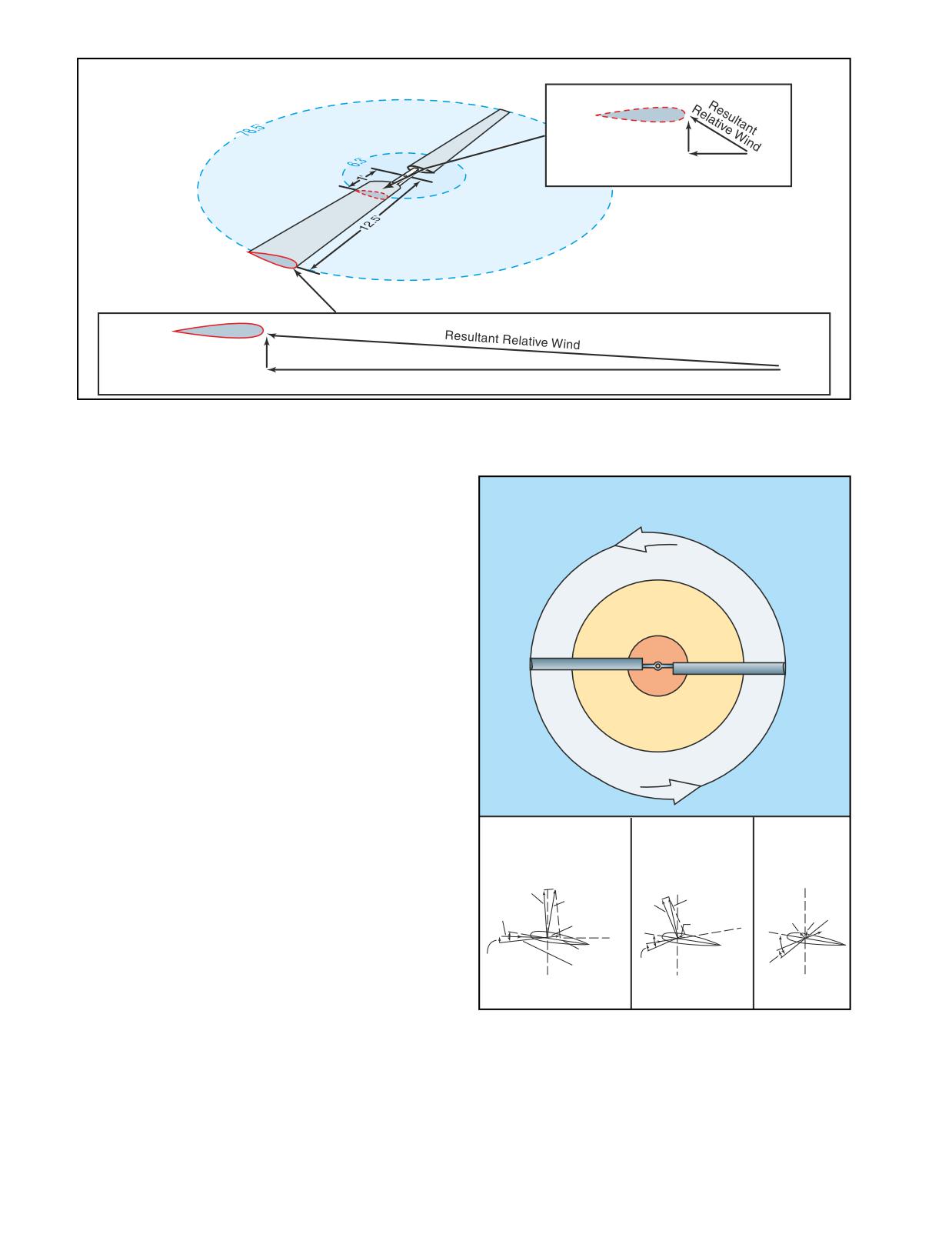
VERTICAL AUTOROTATION
HUB
Upward Airflow
(17 m.p.h. or 25 f.p.s.)
Rotational Airflow
(21 m.p.h. or 31 f.p.s.)
Rotor Speed: 300 r.p.m.
TIP
Upward Airflow
(17 m.p.h. or 25 f.p.s.)
Rotational Airflow (267 m.p.h. or 393 f.p.s.)
Figure 16-3. Moving outboard on the rotor blade, the rotational velocity increasingly exceeds the upward component of airflow,
resulting in a higher relative wind at a lower angle of attack.
speed of 393 feet per second, or 267 m.p.h. The result
is a higher total relative wind, striking the blades at a
VERTICAL AUTOROTATION
lower angle of attack. [Figure 16-3]
ROTOR DISC REGIONS
Driven Region
As with any airfoil, the lift that is created by rotor
blades is perpendicular to the relative wind. Because
Driving Region
the relative wind on rotor blades in autorotation shifts
from a high angle of attack inboard to a lower angle of
Stall
attack outboard, the lift generated has a higher forward
component closer to the hub and a higher vertical com-
Region
ponent toward the blade tips. This creates distinct
regions of the rotor disc that create the forces neces-
sary for flight in autorotation. [Figure 16-4] The
autorotative region, or driving region, creates a total
aerodynamic force with a forward component that
exceeds all rearward drag forces and keeps the blades
spinning. The propeller region, or driven region, gen-
Driven Region
Driving Region
Stall Region
erates a total aerodynamic force with a higher vertical
(Propeller)
(Autorotative)
component that allows the gyroplane to remain aloft.
Total
Total
(Blade is Stalled)
Near the center of the rotor disc is a stall region where
Aerodynamic
Aerodynamic
TAF
Force Aft
Force
the rotational component of the relative wind is so low
Lift
of Axis of
TAF
Forward
Rotation
Lift
of Axis of
that the resulting angle of attack is beyond the stall
Rotational
Rotation
Relative Wind
Lift
TAF
Drag
Drag
limit of the airfoil. The stall region creates drag against
Drag
the direction of rotation that must be overcome by the
Inflow Up
Chord Line
Through Rotor
Inflow
forward acting forces generated by the driving region.
Resultant
Inflow
Relative Wind
Axis of
Axis of
Axis of
Rotation
Rotation
Rotation
AUTOROTATION IN FORWARD FLIGHT
As discussed thus far, the aerodynamics of autorotation
Figure 16-4. The total aerodynamic force is aft of the axis of
rotation in the driven region and forward of the axis of rota-
apply to a gyroplane in a vertical descent. Because
tion in the driving region. Drag is the major aerodynamic
gyroplanes are normally operated in forward flight, the
force in the stall region. For a complete depiction of force
component of relative wind striking the rotor blades as
vectors during a vertical autorotation, refer to Chapter 3-
a result of forward speed must also be considered. This
Aerodynamics of Flight (Helicopter), Figure 3-22.
component has no effect on the aerodynamic principles
that cause the blades to autorotate, but causes a shift in
As a gyroplane moves forward through the air, the for-
the zones of the rotor disc.
ward speed of the aircraft is effectively added to the
16-2
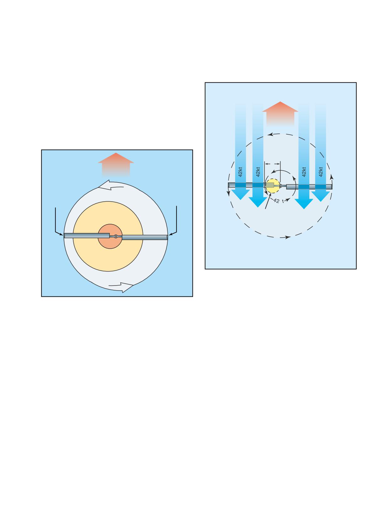
relative wind striking the advancing blade, and sub-
rily on the forward speed of the aircraft, with higher
tracted from the relative wind striking the retreating
speed creating a larger region of reverse flow. To some
blade. To prevent uneven lifting forces on the two sides
degree, the operating speed of the rotor system also has
of the rotor disc, the advancing blade teeters up,
an effect on the size of the region, with systems operat-
decreasing angle of attack and lift, while the retreating
ing at lower r.p.m. being more susceptible to reverse
blade teeters down, increasing angle of attack and lift.
flow and allowing a greater portion of the blade to
(For a complete discussion on dissymmetry of lift, refer
experience the effect.
to Chapter 3-Aerodynamics of Flight.) The lower
angles of attack on the advancing blade cause more of
the blade to fall in the driven region, while higher
angles of attack on the retreating blade cause more of
Forward
the blade to be stalled. The result is a shift in the rotor
Flight at
regions toward the retreating side of the disc to a degree
42 kt
directly related to the forward speed of the aircraft.
[Figure 16-5]
Forward
2'
Retreating
Driven Region
Advancing
Side
Side
k
Area of
Driving Region
Reverse flow
Stall
Region
Rotor Speed 300 r.p.m.
Figure 16-6. An area of reverse flow forms on the retreating
blade in forward flight as a result of aircraft speed exceeding
blade rotational speed.
Figure 16-5. Rotor disc regions in forward autorotative flight.
RETREATING BLADE STALL
The retreating blade stall in a gyroplane differs from
REVERSE FLOW
that of a helicopter in that it occurs outboard from the
On a rotor system in forward flight, reverse flow occurs
rotor hub at the 20 to 40 percent position rather than at
near the rotor hub on the retreating side of the rotor
the blade tip. Because the gyroplane is operating in
disc. This is the result of the forward speed of the air-
autorotation, in forward flight there is an inherent stall
craft exceeding the rotational speed of the rotor blades.
region centered inboard on the retreating blade. [Refer
For example, two feet outboard from the rotor hub, the
to figure 16-5] As forward speed increases, the angle of
blades travel in a circle with a circumference of 12.6
attack on the retreating blade increases to prevent dis-
feet. At a rotor speed of 300 r.p.m., the blade speed at
symmetry of lift and the stall region moves further
the two-foot station is 42 m.p.h. If the aircraft is being
outboard on the retreating blade. Because the stalled
operated at a forward speed of 42 m.p.h., the forward
portion of the rotor disc is inboard rather than near the
speed of the aircraft essentially negates the rotational
tip, as with a helicopter, less force is created about the
velocity on the retreating blade at the two-foot station.
aircraft center of gravity. The result is that you may feel
Moving inboard from the two-foot station on the
a slight increase in vibration, but you would not experi-
retreating blade, the forward speed of the aircraft
ence a large pitch or roll tendency.
increasingly exceeds the rotational velocity of the
blade. This causes the airflow to actually strike the
ROTOR FORCE
trailing edge of the rotor blade, with velocity increas-
As with any heavier than air aircraft, the four forces
ing toward the rotor hub. [Figure 16-6] The size of the
acting on the gyroplane in flight are lift, weight, thrust
area that experiences reverse flow is dependent prima-
and drag. The gyroplane derives lift from the rotor and
16-3
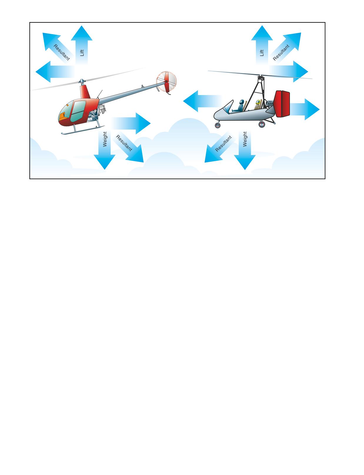
Rotor
Thrust
Drag
Thrust
Fuselage
Drag
Drag
Figure 16-7. Unlike a helicopter, in forward powered flight the resultant rotor force of a gyroplane acts in a rearward direction.
thrust directly from the engine through a propeller.
rotor blades turn, rapid changes occur on the airfoils
[Figure 16-7]
depending on position, rotor speed, and aircraft speed.
A change in the angle of attack of the rotor disc can
The force produced by the gyroplane rotor may be
effect a rapid and substantial change in total rotor drag.
divided into two components; rotor lift and rotor drag.
The component of rotor force perpendicular to the
Rotor drag can be divided into components of induced
flight path is rotor lift, and the component of rotor force
drag and profile drag. The induced drag is a product of
parallel to the flight path is rotor drag. To derive the
lift, while the profile drag is a function of rotor r.p.m.
total aircraft drag reaction, you must also add the drag
Because induced drag is a result of the rotor providing
of the fuselage to that of the rotor.
lift, profile drag can be considered the drag of the rotor
when it is not producing lift. To visualize profile drag,
ROTOR LIFT
consider the drag that must be overcome to prerotate
Rotor lift can most easily be visualized as the lift
the rotor system to flight r.p.m. while the blades are
required to support the weight of the aircraft. When an
producing no lift. This can be achieved with a rotor sys-
airfoil produces lift, induced drag is produced. The
tem having a symmetrical airfoil and a pitch change
most efficient angle of attack for a given airfoil pro-
capability by setting the blades to a 0° angle of attack.
duces the most lift for the least drag. However, the air-
A rotor system with an asymmetrical airfoil and a built
foil of a rotor blade does not operate at this efficient
in pitch angle, which includes most amateur-built
angle throughout the many changes that occur in each
teeter-head rotor systems, cannot be prerotated without
revolution. Also, the rotor system must remain in the
having to overcome the induced drag created as well.
autorotative (low) pitch range to continue turning in
order to generate lift.
THRUST
Thrust in a gyroplane is defined as the component of
Some gyroplanes use small wings for creating lift when
total propeller force parallel to the relative wind. As
operating at higher cruise speeds. The lift provided by
with any force applied to an aircraft, thrust acts around
the wings can either supplement or entirely replace
the center of gravity. Based upon where the thrust is
rotor lift while creating much less induced drag.
applied in relation to the aircraft center of gravity, a rel-
atively small component may be perpendicular to the
ROTOR DRAG
relative wind and can be considered to be additive to
Total rotor drag is the summation of all the drag forces
lift or weight.
acting on the airfoil at each blade position. Each blade
position contributes to the total drag according to the
In flight, the fuselage of a gyroplane essentially acts as
speed and angle of the airfoil at that position. As the
a plumb suspended from the rotor, and as such, it is
16-4
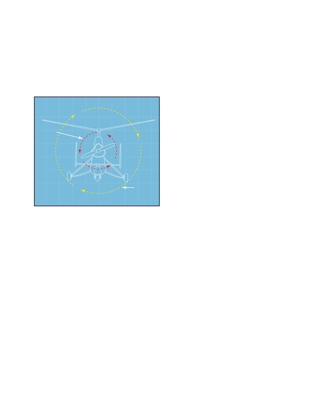
subject to pendular action in the same way as a heli-
There are several factors that contribute to the stability
copter. Unlike a helicopter, however, thrust is applied
of a gyroplane. One is the location of the horizontal
directly to the airframe of a gyroplane rather than being
stabilizer. Another is the location of the fuselage drag
obtained through the rotor system. As a result, different
in relation to the center of gravity. A third is the
forces act on a gyroplane in flight than on a helicopter.
inertia moment around the pitch axis, while a fourth is
Engine torque, for example, tends to roll the fuselage
the relation of the propeller thrust line to the vertical
in the direction opposite propeller rotation, causing it
location of the center of gravity (CG). However, the
to be deflected a few degrees out of the vertical plane.
one that is probably the most critical is the relation of
[Figure 16-8] This slight “out of vertical” condition is
the rotor force line to the horizontal location of the
usually negligible and not considered relevant for most
center of gravity.
flight operations.
HORIZONTAL STABILIZER
A horizontal stabilizer helps in longitudinal stability,
with its efficiency greater the further it is from the
center of gravity. It is also more efficient at higher
airspeeds because lift is proportional to the square of
Torque
the airspeed. Since the speed of a gyroplane is not very
Applied to
Prop
eller
high, manufacturers can achieve the desired stability
by varying the size of the horizontal stabilizer, chang-
ing the distance it is from the center of gravity, or by
placing it in the propeller slipstream.
FUSELAGE DRAG
R
eactive
(CENTER OF PRESSURE)
Torque on
If the location, where the fuselage drag or center of
Fuselage
pressure forces are concentrated, is behind the CG,
the gyroplane is considered more stable. This is espe-
Figure 16-8. Engine torque applied to the propeller has an
cially true of yaw stability around the vertical axis.
equal and opposite reaction on the fuselage, deflecting it a
However, to achieve this condition, there must be a
few degrees out of the vertical plane in flight.
sufficient vertical tail surface. In addition, the gyro-
plane needs to have a balanced longitudinal center of
pressure so there is sufficient cyclic movement to
prevent the nose from tucking under or lifting, as
STABILITY
pressure builds on the frontal area of the gyroplane as
Stability is designed into aircraft to reduce pilot work-
airspeed increases.
load and increase safety. A stable aircraft, such as a typ-
ical general aviation training airplane, requires less
attention from the pilot to maintain the desired flight
PITCH INERTIA
attitude, and will even correct itself if disturbed by a
Without changing the overall weight and center of
gust of wind or other outside forces. Conversely, an
gravity of a gyroplane, the further weights are placed
unstable aircraft requires constant attention to maintain
from the CG, the more stable the gyroplane. For exam-
control of the aircraft.
ple, if the pilot's seat could be moved forward from the
CG, and the engine moved aft an amount, which keeps
the center of gravity in the same location, the gyroplane
becomes more stable. A tightrope walker applies this
same principle when he uses a long pole to balance
himself.
PROPELLER THRUST LINE
Pendular Action-The lateral or
Considering just the propeller thrust line by itself, if the
longitudinal oscillation of the fuse-
thrust line is above the center of gravity, the gyroplane
lage due to it being suspended
from the rotor system. It is similar
has a tendency to pitch nose down when power is
to the action of a pendulum.
applied, and to pitch nose up when power is removed.
Pendular action is further dis-
cussed in Chapter 3-
The opposite is true when the propeller thrust line is
Aerodynamics of Flight.
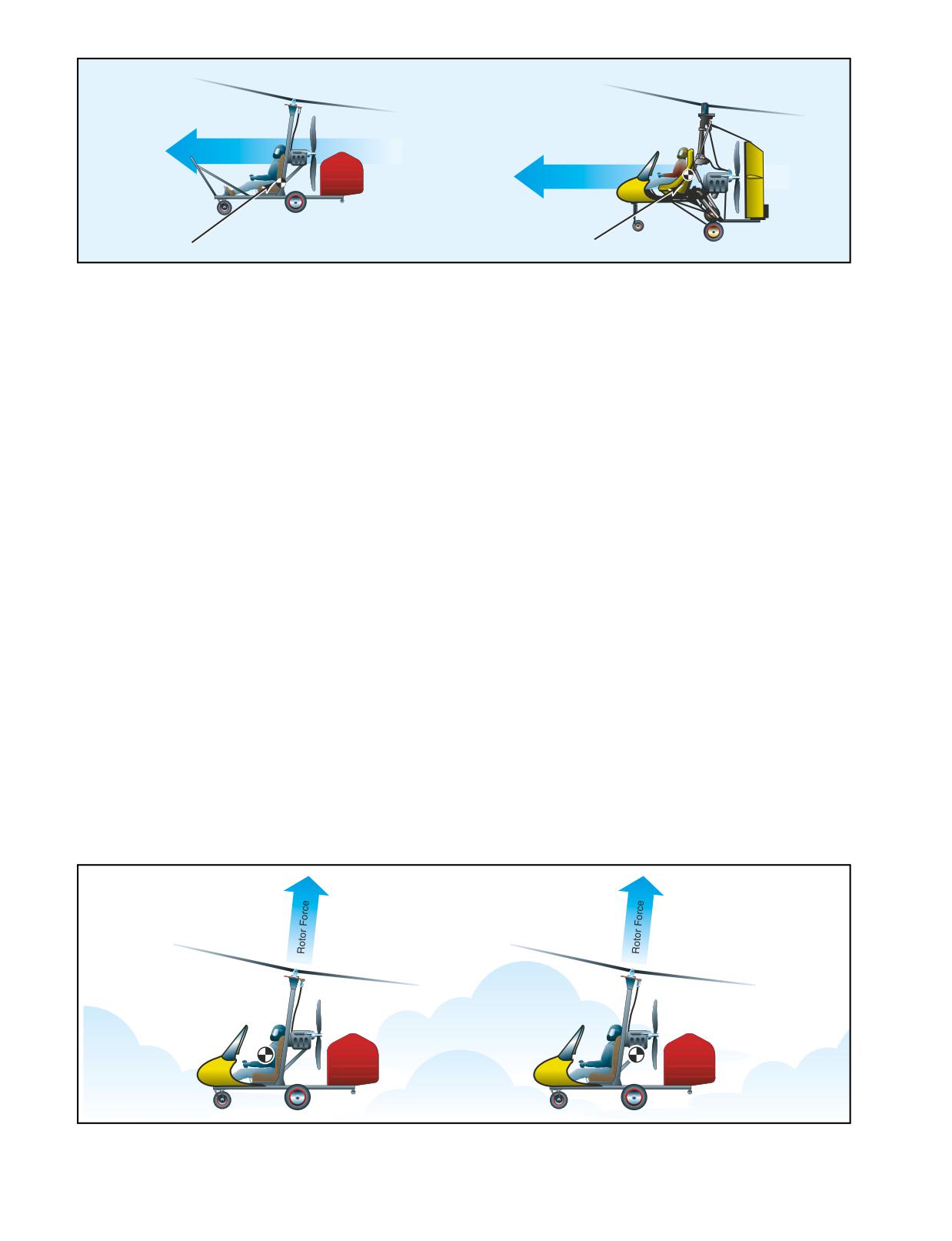
below the CG. If the thrust line goes through the CG or
16-5
Low Profile
High Profile
Propeller Thrust
Propeller Thrust
Center of Gravity
Center of Gravity
Figure 16-9. A gyroplane which has the propeller thrust line above the center of gravity is often referred to as a low profile gyro-
plane. One that has the propeller thrust line below or at the CG is considered a high profile gyroplane.
nearly so there is no tendency for the nose to pitch up
TRIMMED CONDITION
or down. [Figure 16-9]
As was stated earlier, manufacturers use a combination
of the various stability factors to achieve a trimmed
ROTOR FORCE
gyroplane. For example, if you have a gyroplane where
Because some gyroplanes do not have horizontal stabi-
the CG is below the propeller thrust line, the propeller
lizers, and the propeller thrust lines are different, gyro-
thrust gives your aircraft a nose down pitching moment
plane manufacturers can achieve the desired stability
when power is applied. To compensate for this pitching
by placing the center of gravity in front of or behind the
moment, the CG, on this type of gyroplane, is usually
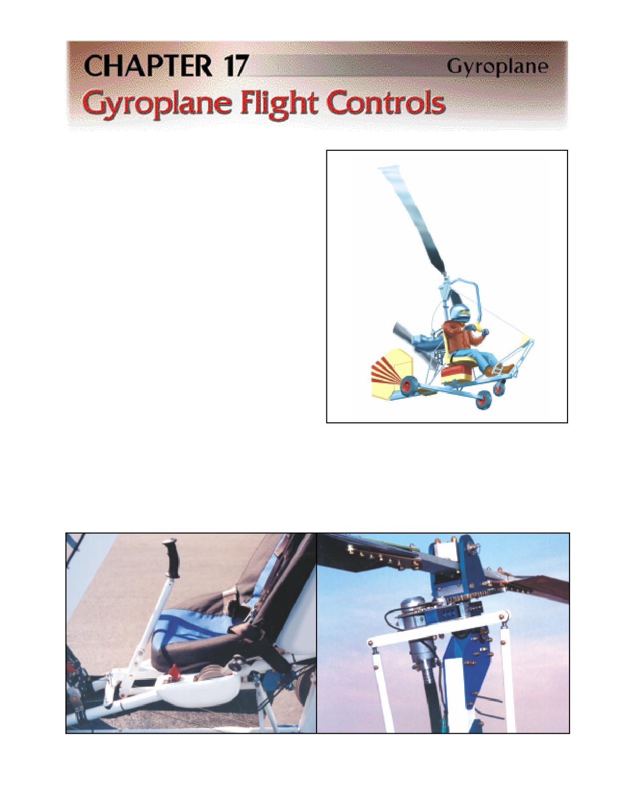
rotor force line. [Figure 16-10]
located behind the rotor force line. This location pro-
duces a nose up pitching moment.
Suppose the CG is located behind the rotor force line in
forward flight. If a gust of wind increases the angle of
Conversely, if the CG is above the propeller thrust line,
attack, rotor force increases. There is also an increase
the CG is usually located ahead of the rotor force line.
in the difference between the lift produced on the
Of course, the location of fuselage drag, the pitch iner-
advancing and retreating blades. This increases the
tia, and the addition of a horizontal stabilizer can alter
flapping angle and causes the rotor to pitch up. This
where the center of gravity is placed.
pitching action increases the moment around the center
of gravity, which leads to a greater increase in the angle
of attack. The result is an unstable condition.
If the CG is in front of the rotor force line, a gust of
wind, which increases the angle of attack, causes the
rotor disc to react the same way, but now the increase
in rotor force and blade flapping decreases the
Blade Flapping-The upward or downward movement of the rotor-
moment. This tends to decrease the angle of attack, and
blades during rotation.
creates a stable condition.
Figure 16-10. If the CG is located in front of the rotor force line, the gyroplane is more stable than if the CG is located behind the
rotor force line.
16-6
Due to rudimentary flight control systems, early gyroplanes
suffered from limited maneuverability. As technology
improved, greater control of the rotor system and more
effective control surfaces were developed. The modern
gyroplane, while continuing to maintain an element of
simplicity, now enjoys a high degree of maneuver-
ability as a result of these improvements.
CYCLIC CONTROL
The cyclic control provides the means whereby you are
able to tilt the rotor system to provide the desired
results. Tilting the rotor system provides all control for
climbing, descending, and banking the gyroplane. The
most common method to transfer stick movement to
the rotor head is through push-pull tubes or flex cables.
[Figure 17-1] Some gyroplanes use a direct overhead
stick attachment rather than a cyclic, where a rigid con-
trol is attached to the rotor hub and descends over and
in front of the pilot. [Figure 17-2] Because of the
nature of the direct attachment, control inputs with this
system are reversed from those used with a cyclic.
Pushing forward on the control causes the rotor disc to
tilt back and the gyroplane to climb, pulling back on
Figure 17-2. The direct overhead stick attachment has been
the control initiates a descent. Bank commands are
used for control of the rotor disc on some gyroplanes.
reversed in the same way.
the control is designed, control movement may or
THROTTLE
may not be proportional to engine power. With many
The throttle is conventional to most powerplants, and
gyroplane throttles, 50 percent of the control travel
provides the means for you to increase or decrease
may equate to 80 or 90 percent of available power.
engine power and thus, thrust. Depending on how
This varying degree of sensitivity makes it necessary
Figure 17-1. A common method of transferring cyclic control inputs to the rotor head is through the use of push-pull tubes,
located outboard of the rotor mast pictured on the right.
17-1
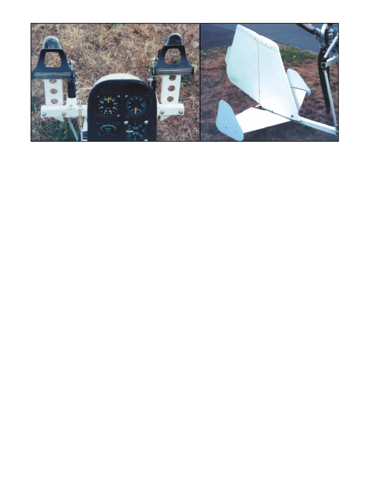
Figure 17-3. Foot pedals provide rudder control and operation is similar to that of an airplane.
for you to become familiar with the unique throttle
stabilizers, are incorporated into gyroplane designs to
characteristics and engine responses for a particular
increase the pitch stability of the aircraft. Some gyro-
gyroplane.
planes use very little, if any, horizontal surface. This
translates into less stability, but a higher degree of
RUDDER
maneuverability. When used, a moveable horizontal
The rudder is operated by foot pedals in the cockpit
surface, or elevator, adds additional pitch control of the
and provides a means to control yaw movement of the
aircraft. On early tractor configured gyroplanes, the
aircraft. [Figure 17-3] On a gyroplane, this control is
elevator served an additional function of deflecting the
achieved in a manner more similar to the rudder of an
propeller slipstream up and through the rotor to assist
airplane than to the antitorque pedals of a helicopter.
in prerotation.
The rudder is used to maintain coordinated flight, and
at times may also require inputs to compensate for
COLLECTIVE CONTROL
propeller torque. Rudder sensitivity and effectiveness
The collective control provides a means to vary the
are directly proportional to the velocity of airflow over
rotor blade pitch of all the blades at the same time, and
the rudder surface. Consequently, many gyroplane
is available only on more advanced gyroplanes. When
rudders are located in the propeller slipstream and
incorporated into the rotor head design, the collective
provide excellent control while the engine is developing
allows jump takeoffs when the blade inertia is suffi-
thrust. This type of rudder configuration, however, is
cient. Also, control of in-flight rotor r.p.m. is available
less effective and requires greater deflection when the
to enhance cruise and landing performance. A simple
engine is idled or stopped.
two position collective does not allow unlimited control
of blade pitch, but instead has one position for prerotation
HORIZONTAL TAIL SURFACES
and another position for flight. This is a performance
The horizontal tail surfaces on most gyroplanes are
compromise but reduces pilot workload by simplifying
not controllable by the pilot. These fixed surfaces, or
control of the rotor system.
17-2
Gyroplanes are available in a wide variety of designs
rotating portion of the head to the non-rotating torque
that range from amateur built to FAA-certificated air-
tube. The torque tube is mounted to the airframe
craft. Similarly, the complexity of the systems inte-
through attachments allowing both lateral and longitu-
grated in gyroplane design cover a broad range. To
dinal movement. This allows the movement through
ensure the airworthiness of your aircraft, it is important
which control is achieved.
that you thoroughly understand the design and opera-
tion of each system employed by your machine.
Tower Plates
Teeter Bolt
PROPULSION SYSTEMS
Most of the gyroplanes flying today use a reciprocating
Tower Block
engine mounted in a pusher configuration that drives
either a fixed or constant speed propeller. The engines
Hub Bar
used in amateur-built gyroplanes are normally proven
Spindle Bolt
powerplants adapted from automotive or other uses.
Some amateur-built gyroplanes use FAA-certificated air-
craft engines and propellers. Auto engines, along with
some of the other powerplants adapted to gyroplanes,
Bearing Block
operate at a high r.p.m., which requires the use of a reduc-
tion unit to lower the output to efficient propeller speeds.
Torque Tube
Early autogyros used existing aircraft engines, which
Fore / Aft Pivot Bolt
drove a propeller in the tractor configuration. Several
amateur-built gyroplanes still use this propulsion con-
Lateral Pivot Bolt
figuration, and may utilize a certificated or an uncer-
tificated engine. Although not in use today, turboprop
and pure jet engines could also be used for the propul-
sion of a gyroplane.
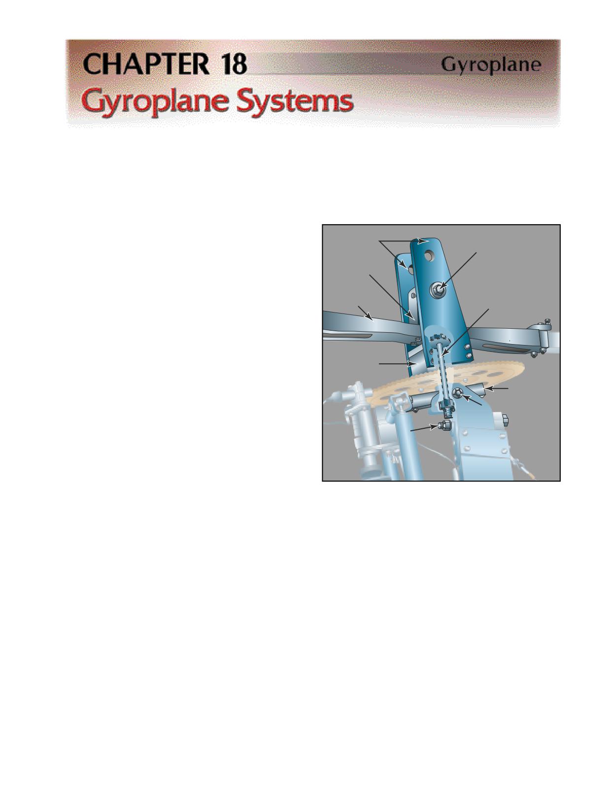
Figure 18-1. The semirigid, teeter-head system is found on
most amateur-built gyroplanes. The rotor hub bar and blades
ROTOR SYSTEMS
are permitted to tilt by the teeter bolt.
SEMIRIGID ROTOR SYSTEM
Any rotor system capable of autorotation may be utilized
in a gyroplane. Because of its simplicity, the most widely
FULLY ARTICULATED ROTOR SYSTEM
used system is the semirigid, teeter-head system. This
The fully articulated rotor system is found on some
system is found in most amateur-built gyroplanes.
gyroplanes. As with helicopter-type rotor systems, the
[Figure 18-1] In this system, the rotor head is mounted
articulated rotor system allows the manipulation of
on a spindle, which may be tilted for control. The rotor
blades are attached to a hub bar that may or may not
have adjustments for varying the blade pitch. Aconing
angle, determined by projections of blade weight,
Coning Angle-An angular
Undersling-A design character-
rotor speed, and load to be carried, is built into the hub
deflection of the rotor blades
istic that prevents the distance
upward from the rotor hub.
between the rotor mast axis and
bar. This minimizes hub bar bending moments and
the center of mass of each rotor
eliminates the need for a coning hinge, which is used
blade from changing as the
in more complex rotor systems. A tower block pro-
blades teeter. This precludes
Coriolis Effect from acting on the
vides the undersling and attachment to the rotor head
speed of the rotor system.
by the teeter bolt. The rotor head is comprised of a
Undersling is further explained
in Chapter 3-Aerodynamics of
bearing block in which the bearing is mounted and
Flight, Coriolis Effect (Law of
onto which the tower plates are attached. The spindle
Conservation of Angular
(commonly, a vertically oriented bolt) attaches the
Momentum).
18-1
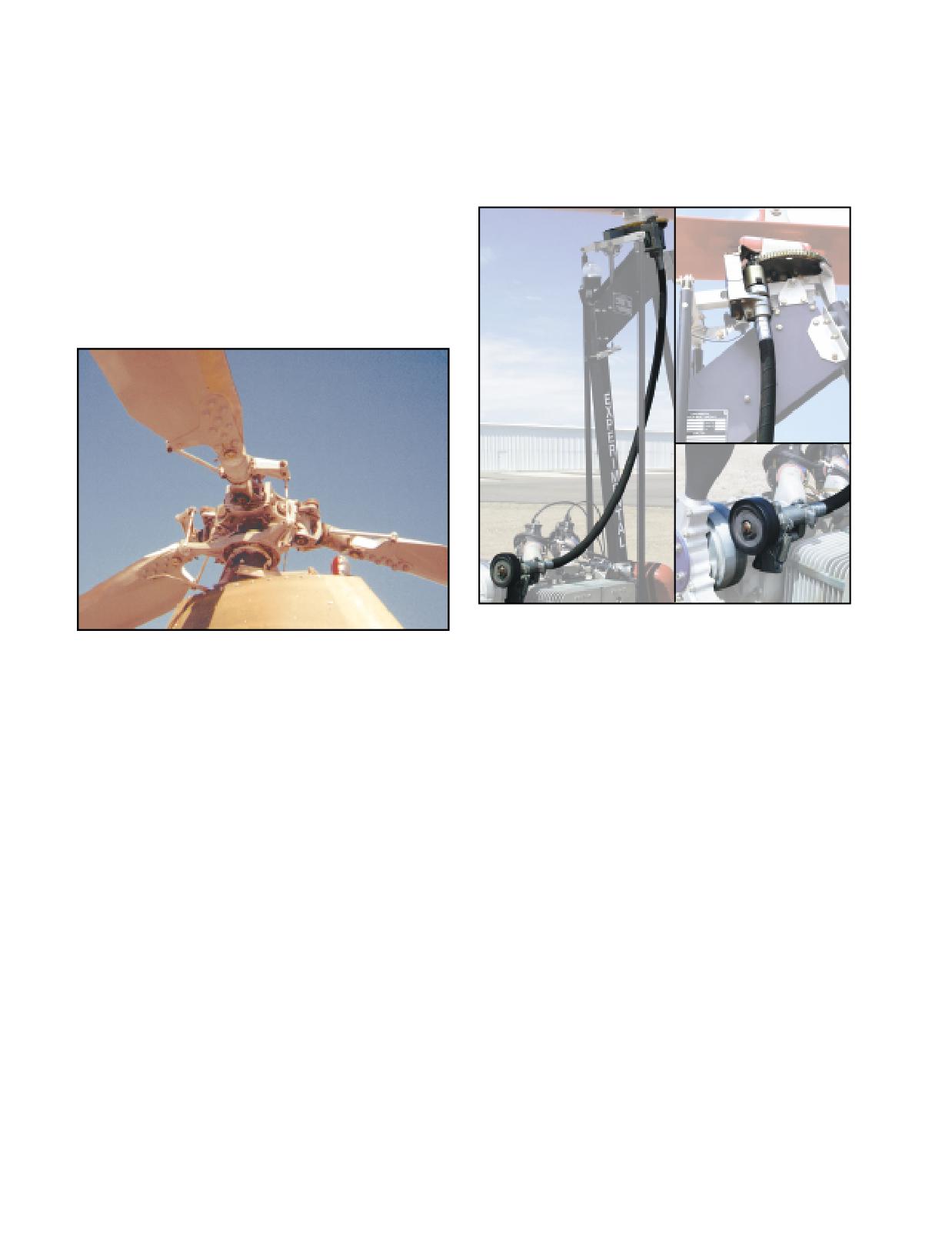
rotor blade pitch while in flight. This system is signifi-
MECHANICAL PREROTATOR
cantly more complicated than the teeter-head, as it
Mechanical prerotators typically have clutches or belts
requires hinges that allow each rotor blade to flap,
for engagement, a drive train, and may use a transmis-
feather, and lead or lag independently. [Figure 18-2]
sion to transfer engine power to the rotor. Friction
When used, the fully articulated rotor system of a gyro-
drives and flex cables are used in conjunction with an
plane is very similar to those used on helicopters, which
automotive type bendix and ring gear on many gyro-
is explained in depth in Chapter 5-Helicopter Systems,
planes. [Figure 18-3]
Main Rotor Systems. One major advantage of using a
fully articulated rotor in gyroplane design is that it usu-
ally allows jump takeoff capability. Rotor characteristics
required for a successful jump takeoff must include a
method of collective pitch change, a blade with sufficient
inertia, and a prerotation mechanism capable of approxi-
mately 150 percent of rotor flight r.p.m.
Figure 18-3. The mechanical prerotator used by many gyro-
planes uses a friction drive at the propeller hub, and a flexi-
Figure 18-2. The fully articulated rotor system enables the
ble cable that runs from the propeller hub to the rotor mast.
pilot to effect changes in pitch to the rotor blades, which is
When engaged, the bendix spins the ring gear located on the
necessary for jump takeoff capability.
rotor hub.
Incorporating rotor blades with high inertia potential is
desirable in helicopter design and is essential for jump
The mechanical prerotator used on jump takeoff gyro-
takeoff gyroplanes. A rotor hub design allowing the
planes may be regarded as being similar to the helicopter
rotor speed to exceed normal flight r.p.m. by over
main rotor drive train, but only operates while the air-
50 percent is not found in helicopters, and predicates a
craft is firmly on the ground. Gyroplanes do not have an
rotor head design particular to the jump takeoff
antitorque device like a helicopter, and ground contact is
gyroplane, yet very similar to that of the helicopter.
necessary to counteract the torque forces generated by
the prerotation system. If jump takeoff capability is
PREROTATOR
designed into a gyroplane, rotor r.p.m. prior to liftoff
Prior to takeoff, the gyroplane rotor must first achieve
must be such that rotor energy will support the air-
a rotor speed sufficient to create the necessary lift.
craft through the acceleration phase of takeoff. This
This is accomplished on very basic gyroplanes by ini-
combination of rotor system and prerotator utilizes
tially spinning the blades by hand. The aircraft is then
the transmission only while the aircraft is on the
taxied with the rotor disc tilted aft, allowing airflow
ground, allowing the transmission to be disconnected
through the system to accelerate it to flight r.p.m.
from both the rotor and the engine while in normal
More advanced gyroplanes use a prerotator, which
flight.
provides a mechanical means to spin the rotor. Many
prerotators are capable of only achieving a portion of
HYDRAULIC PREROTATOR
the speed necessary for flight; the remainder is
The hydraulic prerotator found on gyroplanes uses
gained by taxiing or during the takeoff roll. Because
engine power to drive a hydraulic pump, which in turn
of the wide variety of prerotation systems available,
drives a hydraulic motor attached to an automotive type
you need to become thoroughly familiar with the
bendix and ring gear. [Figure 18-4] This system also
characteristics and techniques associated with your
requires that some type of clutch and pressure regula-
particular system.
tion be incorporated into the design.
18-2
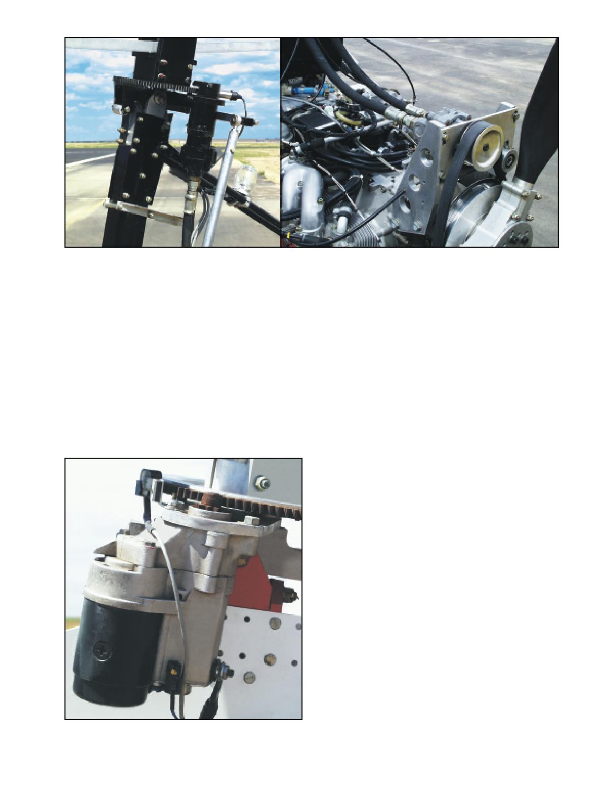
Figure 18-4. This prerotator uses belts at the propeller hub to drive a hydraulic pump, which drives a hydraulic motor on the
rotor mast.
ELECTRIC PREROTATOR
TIP JETS
The electric prerotator found on gyroplanes uses an
Jets located at the rotor blade tips have been used in sev-
automotive type starter with a bendix and ring gear
eral applications for prerotation, as well as for hover
mounted at the rotor head to impart torque to the rotor
flight. This system has no requirement for a transmission
system. [Figure 18-5] This system has the advantage of
or clutches. It also has the advantage of not imparting
simplicity and ease of operation, but is dependent on
torque to the airframe, allowing the rotor to be powered
having electrical power available. Using a “soft start”
in flight to give increased climb rates and even the ability
device can alleviate the problems associated with the
to hover. The major disadvantage is the noise generated
high starting torque initially required to get the rotor
by the jets. Fortunately, tip jets may be shut down while
system turning. This device delivers electrical pulses to
operating in the autorotative gyroplane mode.
the starter for approximately 10 seconds before con-
necting uninterrupted voltage.
INSTRUMENTATION
The instrumentation required for flight is generally
related to the complexity of the gyroplane. Some gyro-
planes using air-cooled and fuel/oil-lubricated engines
may have limited instrumentation.
ENGINE INSTRUMENTS
All but the most basic engines require monitoring
instrumentation for safe operation. Coolant tempera-
ture, cylinder head temperatures, oil temperature, oil
pressure, carburetor air temperature, and exhaust gas
temperature are all direct indications of engine opera-
tion and may be displayed. Engine power is normally
indicated by engine r.p.m., or by manifold pressure on
gyroplanes with a constant speed propeller.
ROTOR TACHOMETER
Most gyroplanes are equipped with a rotor r.p.m. indica-
tor. Because the pilot does not normally have direct
control of rotor r.p.m. in flight, this instrument is most
useful on the takeoff roll to determine when there is suf-
ficient rotor speed for liftoff. On gyroplanes not
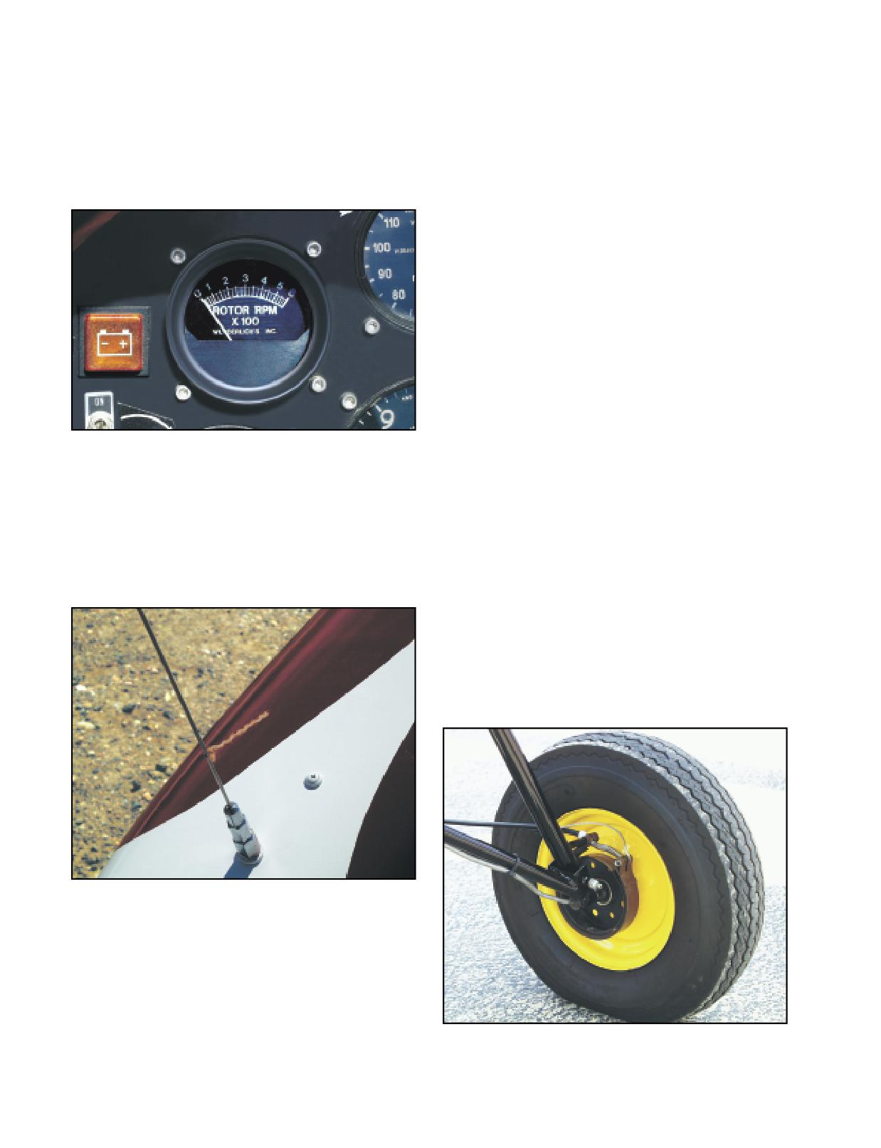
Figure 18-5. The electric prerotator is simple and easy to use,
equipped with a rotor tachometer, additional piloting
but requires the availability of electrical power.
skills are required to sense rotor r.p.m. prior to takeoff.
18-3
Certain gyroplane maneuvers require you to know pre-
speed indicator is used, as in some very basic
cisely the speed of the rotor system. Performing a jump
amateur-built machines, you must have a very acute
takeoff in a gyroplane with collective control is one
sense of “q” (impact air pressure against your body).
example, as sufficient rotor energy must be available
for the successful outcome of the maneuver. When
ALTIMETER
variable collective and a rotor tachometer are used,
For the average pilot, it becomes increasingly difficult
more efficient rotor operation may be accomplished by
to judge altitude accurately when more than several
using the lowest practical rotor r.p.m. [Figure 18-6]
hundred feet above the ground. A conventional altime-
ter may be used to provide an altitude reference when
flying at higher altitudes where human perception
degrades.
IFR FLIGHT INSTRUMENTATION
Gyroplane flight into instrument meteorological condi-
tions requires adequate flight instrumentation and navi-
gational systems, just as in any aircraft. Very few
gyroplanes have been equipped for this type of operation.
The majority of gyroplanes do not meet the stability
requirements for single-pilot IFR flight. As larger and
more advanced gyroplanes are developed, issues of IFR
flight in these aircraft will have to be addressed.
Figure 18-6. A rotor tachometer can be very useful to deter-
mine when rotor r.p.m. is sufficient for takeoff.
GROUND HANDLING
The gyroplane is capable of ground taxiing in a manner
similar to that of an airplane. A steerable nose wheel,
SLIP/SKID INDICATOR
which may be combined with independent main wheel
A yaw string attached to the nose of the aircraft and a
brakes, provides the most common method of control.
conventional inclinometer are often used in gyroplanes
[Figure 18-8] The use of independent main wheel
to assist in maintaining coordinated flight. [Figure 18-7]
brakes allows differential braking, or applying more
braking to one wheel than the other to achieve tight
radius turns. On some gyroplanes, the steerable nose
wheel is equipped with a foot-operated brake rather
than using main wheel brakes. One limitation of this
system is that the nose wheel normally supports only a
fraction of the weight of the gyroplane, which greatly
reduces braking effectiveness. Another drawback is the
Figure 18-7. A string simply tied near the nose of the gyro-
plane that can be viewed from the cockpit is often used to
indicate rotation about the yaw axis. An inclinometer may
also be used.
AIRSPEED INDICATOR
Airspeed knowledge is essential and is most easily
obtained by an airspeed indicator that is designed for
Figure 18-8. Depending on design, main wheel brakes can be
accuracy at low airspeeds. Wind speed indicators
operated either independently or collectively. They are con-
have been adapted to many gyroplanes. When no air-
siderably more effective than nose wheel brakes.
18-4
inability to use differential braking, which increases
brake that may be used to slow the rotor after landing,
the radius of turns.
or to secure the blades while parked. A parked gyro-
plane should never be left with unsecured blades,
The rotor blades demand special consideration during
because even a slight change in wind could cause the
ground handling, as turning rotor blades can be a haz-
blades to turn or flap.
ard to those nearby. Many gyroplanes have a rotor
18-5
18-6
As with most certificated aircraft manufactured after
This format is the same as that used by helicopters,
March 1979, FAA-certificated gyroplanes are required
which is explained in depth in Chapter 6-Rotorcraft
to have an approved flight manual. The flight manual
Flight Manual (Helicopter).
describes procedures and limitations that must be
adhered to when operating the aircraft. Specification
Amateur-built gyroplanes may have operating limita-
for Pilot’s Operating Handbook, published by the
tions but are not normally required to have an approved
General Aviation Manufacturers Association (GAMA),
flight manual. One exception is an exemption granted
provides a recommended format that more recent gyro-
by the FAA that allows the commercial use of
plane flight manuals follow. [Figure 19-1]
two-place, amateur-built gyroplanes for instructional
purposes. One of the conditions of this exemption is to
have an approved flight manual for the aircraft. This
ROTORCRAFT FLIGHT MANUAL
manual is to be used for training purposes, and must be
GENERAL-Presents basic information, such as loading,
carried in the gyroplane at all times.
handling, and preflight of the gyroplane. Also includes
definitions, abbreviations, symbology, and terminology
explanations.
USING THE FLIGHT MANUAL
LIMITATIONS-Includes operating limitations, instrument
markings, color coding, and basic placards necessary for the
The flight manual is required to be on board the aircraft
safe operation of the gyroplane.
to guarantee that the information contained therein is
EMERGENCY PROCEDURES-Provides checklists followed
readily available. For the information to be of value,
by amplified procedures for coping with various types of
you must be thoroughly familiar with the manual and
emergencies or critical situations. Related recommended
be able to read and properly interpret the various charts
airspeeds are also included. At the manufacturer's option, a
section of abnormal procedures may be included to describe
and tables.
recommendations for handling equipment malfunctions or other
abnormalities that are not of an emergency nature.
NORMAL PROCEDURES-Includes checklists followed by
WEIGHT AND BALANCE SECTION
amplified procedures for conducting normal operations.
The weight and balance section of the flight manual
Related recommended airspeeds are also provided.
contains information essential to the safe operation of
PERFORMANCE-Gives
performance
information
the gyroplane. Careful consideration must be given to
appropriate to the gyroplane, plus optional information
the weight of the passengers, baggage, and fuel prior to
presented in the most likely order for use in flight.
each flight. In conducting weight and balance compu-
WEIGHT AND BALANCE-Includes weighing procedures,
weight and balance records, computation instructions, and
tations, many of the terms and procedures are similar to
the equipment list.
those used in helicopters. These are further explained
AIRCRAFT AND SYSTEMS DESCRIPTION-Describes the
in Chapter 7-Weight and Balance. In any aircraft,
gyroplane and its systems in a format considered by the
failure to adhere to the weight and balance limita-
manufacturer to be most informative.
tions prescribed by the manufacturer can be
HANDLING, SERVICE, AND MAINTENANCE-Includes
extremely hazardous.
information on gyroplane inspection periods, preventative
maintenance that can be performed by the pilot, ground
handling procedures, servicing, cleaning, and care instructions.
SAMPLE PROBLEM
SUPPLEMENTS-Contains information necessary to safely
As an example of a weight and balance computation,
and efficiently operate the gyroplane's various optional
systems and equipment.
assume a sightseeing flight in a two-seat, tandem-con-
figured gyroplane with two people aboard. The pilot,
SAFETY AND OPERATIONAL TIPS-Includes optional
seated in the front, weighs 175 pounds while the rear
information from the manufacturer of a general nature
addressing safety practices and procedures.
seat passenger weighs 160 pounds. For the purposes of
this example, there will be no baggage carried. The
Figure 19-1. The FAA-approved flight manual may contain as
basic empty weight of the aircraft is 1,315 pounds with
many as ten sections, as well as an optional alphabetical
index.
a moment, divided by 1,000, of 153.9 pound-inches.
19-1
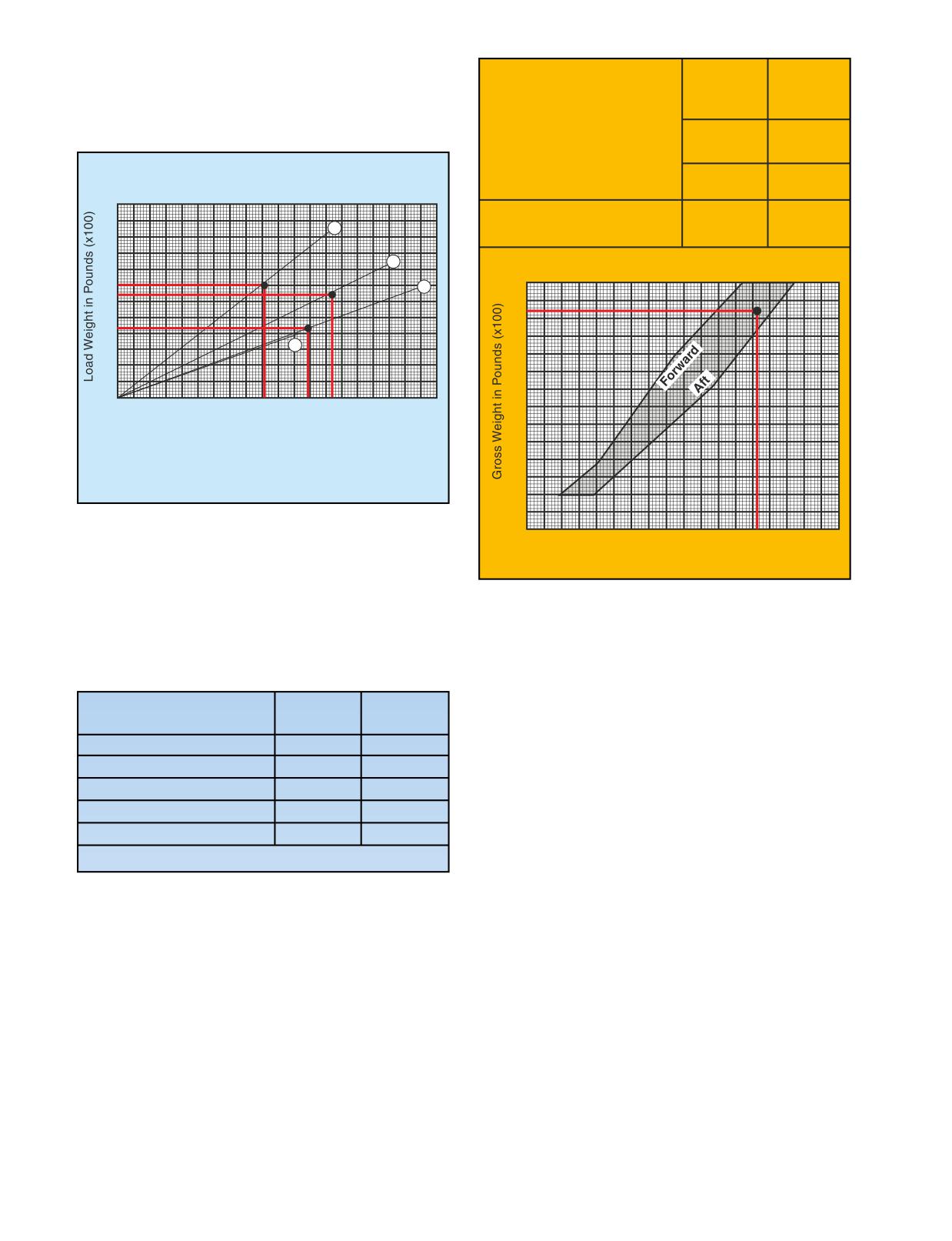
Using the loading graph [Figure
19-2], the
Moment
Weight
moment/1000 of the pilot is found to be 9.1 pound-
(lb.-ins.
(lbs.)
inches, and the passenger has a moment/1000 of 13.4
/1,000)
pound-inches.
1. Total Aircraft Weight
(Less Fuel)
1,650
176.4
3. Fuel
108
11.9
LOADING GRAPH
3
A
TOTALS
1,758
188.3
B
2
CENTER OF GRAVITY ENVELOPE
18
C
1
D
17
0
2
4
6
8
10
12
14
16
18
20
16
Load Moment in Thousands of LBS - IN
A = Pilot
C = Fuel
B = Passenger
D = Baggage
15
Figure 19-2. A loading graph is used to determine the load
moment for weights at various stations.
160
170
180
190
200
Gross Moment in Thousands of LBS-IN.
Figure 19-4. Center of gravity envelope chart.
Adding these figures, the total weight of the aircraft for
this flight (without fuel) is determined to be 1,650
pounds with a moment/1000 of 176.4 pound-inches.
[Figure 19-3]
PERFORMANCE SECTION
The performance section of the flight manual contains
data derived from actual flight testing of the aircraft.
Weight
Moment
Because the actual performance may differ, it is pru-
(pounds)
(lb.-in./1,000)
dent to maintain a margin of safety when planning
Basic Empty Weight
1,315
153.9
operations using this data.
Pilot
175
9.1
Passenger
160
13.4
SAMPLE PROBLEM
Baggage
0
0
For this example, a gyroplane at its maximum gross
Total Aircraft (Less Fuel)
1,650
176.4
weight (1,800 lbs.) needs to perform a short field take-
Max Gross Weight = 1,800 lbs.
off due to obstructions in the takeoff path. Present
weather conditions are standard temperature at a pres-
Figure 19-3. Loading of the sample aircraft, less fuel.
sure altitude of 2,000 feet, and the wind is calm.
Referring to the appropriate performance chart [Figure
19-5], the takeoff distance to clear a 50-foot obstacle is
The maximum gross weight for the sample aircraft is
determined by entering the chart from the left at the
1,800 pounds, which allows up to 150 pounds to be car-
pressure altitude of 2,000 feet. You then proceed hori-
ried in fuel. For this flight, 18 gallons of fuel is deemed
zontally to the right until intersecting the appropriate
sufficient. Allowing six pounds per gallon of fuel, the
temperature reference line, which in this case is the
fuel weight on the aircraft totals 108 pounds. Referring
dashed standard temperature line. From this point,
again to the loading graph [Figure 19-2], 108 pounds of
descend vertically to find the total takeoff distance to
fuel would have a moment/1000 of 11.9 pound-inches.
clear a 50-foot obstacle. For the conditions given, this
This is added to the previous totals to obtain the total
particular gyroplane would require a distance of 940
aircraft weight of 1,758 pounds and a moment/1000 of
feet for ground roll and the distance needed to climb 50
188.3. Locating this point on the center of gravity enve-
feet above the surface. Notice that the data presented in
lope chart [Figure 19-4], shows that the loading is
this chart is predicated on certain conditions, such as a
within the prescribed weight and balance limits.
running takeoff to 30 m.p.h., a 50 m.p.h. climb speed, a
19-2
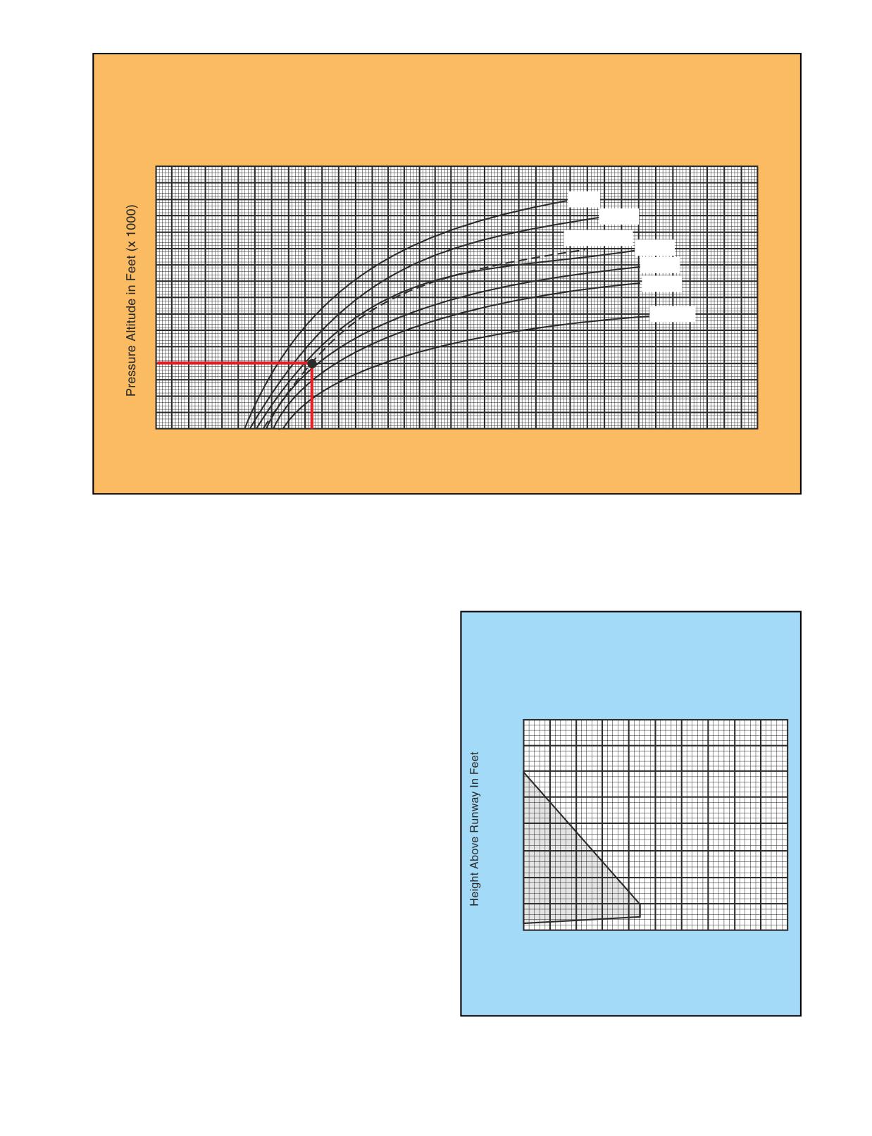
TOTAL TAKEOFF DISTANCE
TO CLEAR 50 FT. OBSTACLE
Running Takeoff to 30 MPH & Climb out at 50 MPH CAS
Weight 1800 LBS
Rotor Prerotated to 370 RPM
Zero Wind
8
7
0° F
20° F
6
Std. Temp.
40° F
5
60° F
80° F
4
100° F
3
2
1
2
4
6
8
10
12
14
16
18
20
22
24
26
28
30
32
34
36
Total Takeoff Distance to Clear 50 FT Obstacle in Feet (x 100)
Figure 19-5. Takeoff performance chart.
rotor prerotation speed of 370 r.p.m., and no wind.
which provide important information that may not be
Variations from these conditions alter performance,
committed to memory.
possibly to the point of jeopardizing the successful out-
come of the maneuver.
HEIGHT/VELOCITY DIAGRAM
HEIGHT vs. VELOCITY
FOR SAFE LANDING
Like helicopters, gyroplanes have a height/velocity
diagram that defines what speed and altitude combina-
Avoid Continuous Operation In
tions allow for a safe landing in the event of an engine
Shaded Area.
failure. [Figure 19-6]
400
During an engine-out landing, the cyclic flare is used to
300
arrest the vertical velocity of the aircraft and most of the
forward velocity. On gyroplanes with a manual collec-
tive control, increasing blade pitch just prior to touch-
200
down can further reduce ground roll. Typically, a
gyroplane has a lower rotor disc loading than a helicop-
ter, which provides a slower rate of descent in autorota-
100
tion. The power required to turn the main transmission,
tail rotor transmission, and tail rotor also add to the
higher descent rate of a helicopter in autorotation as
0
compared with that of a gyroplane.
0
20
40
60
80
100
Indicated Airspeed In MPH
EMERGENCY SECTION
Because in-flight emergencies may not allow enough
time to reference the flight manual, the emergency sec-
tion should be reviewed periodically to maintain
Figure
19-6. Operations within the shaded area of a
familiarity with these procedures. Many aircraft also
height/velocity diagram may not allow for a safe landing and
use placards and instrument markings in the cockpit,
are to be avoided.
19-3
gyroplane hangs. This number must be within the
HANG TEST
range specified by the manufacturer. For the test to
The proper weight and balance of a gyroplane without
reflect the true balance of the aircraft, it is important
a flight manual is normally determined by conducting
that it be conducted using the actual weight of the pilot
a hang test of the aircraft. This is achieved by remov-
and all gear normally carried in flight. Additionally,
ing the rotor blades and suspending the aircraft by its
the measurement should be taken both with the fuel
teeter bolt, free from contact with the ground. A meas-
tank full and with it empty to ensure that fuel burn
urement is then taken, either at the keel or the rotor
does not affect the loading.
mast, to determine how many degrees from level the
19-4
The diversity of gyroplane designs available today
potential. The placement and accessibility of charts,
yields a wide variety of capability and performance.
writing materials, and other necessary items must be
For safe operation, you must be thoroughly familiar
carefully considered. Gyroplanes with open cockpits
with the procedures and limitations for your particular
add the challenge of coping with wind, which further
aircraft along with other factors that may affect the
increases the need for creative and resourceful cockpit
safety of your flight.
management for optimum efficiency.
PREFLIGHT
ENGINE STARTING
As pilot in command, you are the final authority in
The dissimilarity between the various types of engines
determining the airworthiness of your aircraft.
used for gyroplane propulsion necessitates the use of
Adherence to a preflight checklist greatly enhances
an engine start checklist. Again, when a checklist is not
your ability to evaluate the fitness of your gyroplane by
provided, it is advisable to create one for the safety of
ensuring that a complete and methodical inspection of
yourself and others, and to prevent inadvertent damage
all components is performed. [Figure 20-1] For aircraft
to the engine or propeller. Being inherently dangerous,
without a formal checklist, it is prudent to create one
the propeller demands special attention during engine
that is specific to the aircraft to be sure that important
starting procedures. Always ensure that the propeller
items are not overlooked. To determine the status of
area is clear prior to starting. In addition to providing
required inspections, a preflight review of the aircraft
an added degree of safety, being thoroughly familiar
records is also necessary.
with engine starting procedures and characteristics can
also be very helpful in starting an engine under various
weather conditions.
TAXIING
The ability of the gyroplane to be taxied greatly
enhances its utility. However, a gyroplane should not
be taxied in close proximity to people or obstructions
while the rotor is turning. In addition, taxi speed should
be limited to no faster than a brisk walk in ideal condi-
tions, and adjusted appropriately according to the
circumstances.
BLADE FLAP
On a gyroplane with a semi-rigid, teeter-head rotor sys-
tem, blade flap may develop if too much airflow passes
through the rotor system while it is operating at low
r.p.m. This is most often the result of taxiing too fast
Figure 20-1. A checklist is extremely useful in conducting a
thorough preflight inspection.
for a given rotor speed. Unequal lift acting on the
advancing and retreating blades can cause the blades to
teeter to the maximum allowed by the rotor head
design. The blades then hit the teeter stops, creating a
COCKPIT MANAGEMENT
vibration that may be felt in the cyclic control. The fre-
As in larger aircraft, cockpit management is an impor-
quency of the vibration corresponds to the speed of the
tant skill necessary for the safe operation of a
rotor, with the blades hitting the stops twice during
gyroplane. Intrinsic to these typically small aircraft is a
each revolution. If the flapping is not controlled, the
limited amount of space that must be utilized to its
situation can grow worse as the blades begin to flex and
20-1
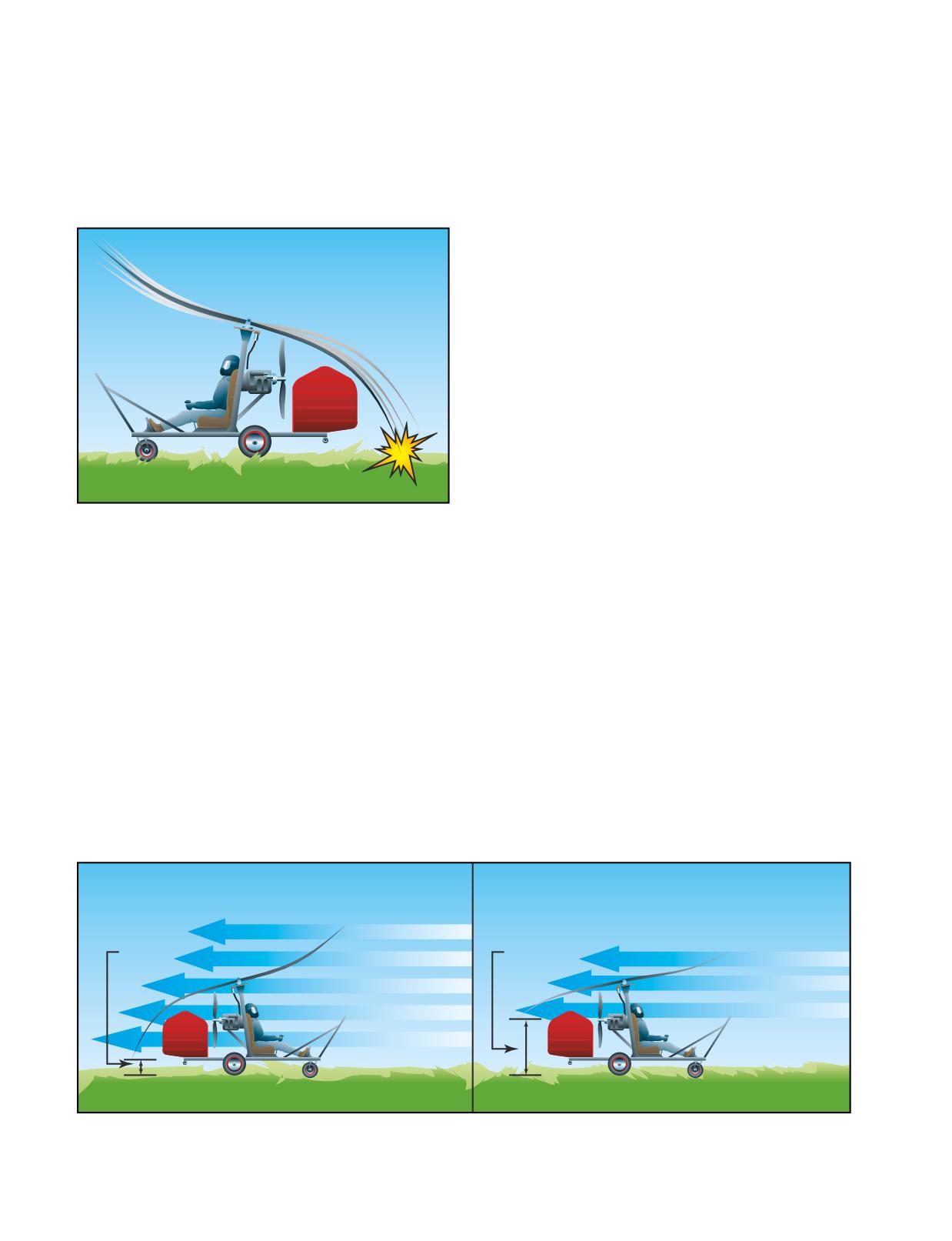
bend. Because the system is operating at low r.p.m.,
BEFORE TAKEOFF
there is not enough centrifugal force acting on the
For the amateur-built gyroplane using single ignition
blades to keep them rigid. The shock of hitting the
and a fixed trim system, the before takeoff check is
teeter stops combined with uneven lift along the length
quite simple. The engine should be at normal operating
of the blade causes an undulation to begin, which can
temperature, and the area must be clear for prerotation.
increase in severity if allowed to progress. In extreme
Certificated gyroplanes using conventional aircraft
cases, a rotor blade may strike the ground or propeller.
engines have a checklist that includes items specific to
[Figure 20-2]
the powerplant. These normally include, but are not
limited to, checks for magneto drop, carburetor heat,
and, if a constant speed propeller is installed, that it be
cycled for proper operation.
Following the engine run-up is the procedure for
accomplishing prerotation. This should be reviewed
and committed to memory, as it typically requires both
hands to perform.
PREROTATION
Prerotation of the rotor can take many forms in a
gyroplane. The most basic method is to turn the rotor
blades by hand. On a typical gyroplane with a counter-
clockwise rotating rotor, prerotation by hand is done on
the right side of the rotor disk. This allows body
Figure 20-2. Taxiing too fast or gusting winds can cause
movement to be directed away from the propeller to
blade flap in a slow turning rotor. If not controlled, a rotor
minimize the risk of injury. Other methods of prerota-
blade may strike the ground.
tion include using mechanical, electrical, or hydraulic
means for the initial blade spin-up. Many of these
systems can achieve only a portion of the rotor speed
To avoid the onset of blade flap, always taxi the gyro-
that is necessary for takeoff. After the prerotator is
plane at slow speeds when the rotor system is at low
disengaged, taxi the gyroplane with the rotor disk tilted
r.p.m. Consideration must also be given to wind speed
aft to allow airflow through the rotor. This increases
and direction. If taxiing into a 10-knot headwind, for
rotor speed to flight r.p.m. In windy conditions, facing
example, the airflow through the rotor will be 10 knots
the gyroplane into the wind during prerotation assists
faster than the forward speed of the gyroplane, so the
in achieving the highest possible rotor speed from the
taxi speed should be adjusted accordingly. When pre-
prerotator. A factor often overlooked that can nega-
rotating the rotor by taxiing with the rotor disc tilted
tively affect the prerotation speed is the cleanliness of
aft, allow the rotor to accelerate slowly and smoothly.
the rotor blades. For maximum efficiency, it is recom-
In the event blade flap is encountered, apply forward
mended that the rotor blades be cleaned periodically.
cyclic to reduce the rotor disc angle and slow the gyro-
By obtaining the maximum possible rotor speed
plane by reducing throttle and applying the brakes, if
through the use of proper prerotation techniques, you
needed. [Figure 20-3]
Rotor
Rotor
Ground
Ground
Clearance
Clearance
Airflow
Airflow
Figure 20-3. Decreasing the rotor disc angle of attack with forward cyclic can reduce the excessive amount of airflow causing
the blade flap. This also allows greater clearance between the rotor blades and the surface behind the gyroplane, minimizing
the chances of a blade striking the ground.
20-2
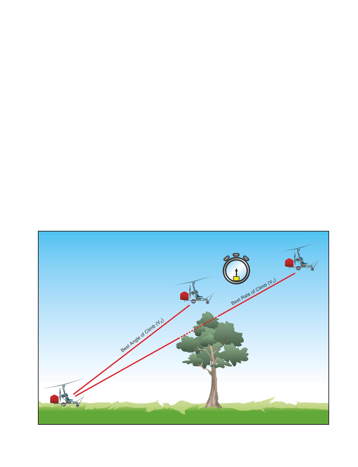
minimize the length of the ground roll that is required
NORMAL TAKEOFF
to get the gyroplane airborne.
The normal takeoff assumes that a prepared surface of
adequate length is available and that there are no high
The prerotators on certificated gyroplanes remove the
obstructions to be cleared within the takeoff path. The
possibility of blade flap during prerotation. Before the
normal takeoff for most amateur-built gyroplanes is
clutch can be engaged, the pitch must be removed from
accomplished by prerotating to sufficient rotor r.p.m. to
the blades. The rotor is then prerotated with a 0° angle
prevent blade flapping and tilting the rotor back with
of attack on the blades, which prevents lift from being
cyclic control. Using a speed of 20 to 30 m.p.h., allow
produced and precludes the possibility of flapping.
the rotor to accelerate and begin producing lift. As lift
When the desired rotor speed is achieved, blade pitch is
increases, move the cyclic forward to decrease the pitch
increased for takeoff.
angle on the rotor disc. When appreciable lift is being
produced, the nose of the aircraft rises, and you can feel
an increase in drag. Using coordinated throttle and
TAKEOFF
flight control inputs, balance the gyroplane on the main
Takeoffs are classified according to the takeoff surface,
gear without the nose wheel or tail wheel in contact
obstructions, and atmospheric conditions. Each type of
with the surface. At this point, smoothly increase power
takeoff assumes that certain conditions exist. When
to full thrust and hold the nose at takeoff attitude with
conditions dictate, a combination of takeoff techniques
cyclic pressure. The gyroplane will lift off at or near
can be used. Two important speeds used for takeoff and
the minimum power required speed for the aircraft. VX
initial climbout are VX and VY. VX is defined as the
should be used for the initial climb, then VY for the
speed that provides the best angle of climb, and will
remainder of the climb phase.
yield the maximum altitude gain over a given distance.
This speed is normally used when obstacles on the
A normal takeoff for certificated gyroplanes is accom-
ground are a factor. Maintaining VY speed ensures the
plished by prerotating to a rotor r.p.m. slightly above
aircraft will climb at its maximum rate, providing the
that required for flight and disengaging the rotor drive.
most altitude gain for a given period of time.
The brakes are then released and full power is applied.
[Figure 20-4] Prior to any takeoff or maneuver, you
Lift off will not occur until the blade pitch is increased
should ensure that the area is clear of other traffic.
to the normal in-flight setting and the rotor disk tilted
30
Figure 20-4. Best angle-of-climb (VX) speed is used when obstacles are a factor. VY provides the most altitude gain for a given
amount of time.
20-3
aft. This is normally accomplished at approximately 30
power applied as soon as appreciable lift is felt. VX
to 40 m.p.h. The gyroplane should then be allowed to
climb speed should be maintained until the obstruction
accelerate to VX for the initial climb, followed by VY
is cleared. Familiarity with the rotor acceleration
for the remainder of the climb. On any takeoff in a
characteristics and proper technique are essential for
gyroplane, engine torque causes the aircraft to roll
optimum short-field performance.
opposite the direction of propeller rotation, and
adequate compensation must be made.
If the prerotator is capable of spinning the rotor in
excess of normal flight r.p.m., the stored energy may be
CROSSWIND TAKEOFF
used to enhance short-field performance. Once maxi-
A crosswind takeoff is much like a normal takeoff,
mum rotor r.p.m. is attained, disengage the rotor drive,
except that you have to use the flight controls to
release the brakes, and apply power. As airspeed and
compensate for the crosswind component. The term
rotor r.p.m. increase, apply additional power until full
crosswind component refers to that part of the wind
power is achieved. While remaining on the ground,
which acts at right angles to the takeoff path. Before
accelerate the gyroplane to a speed just prior to VX. At
attempting any crosswind takeoff, refer to the flight
that point, tilt the disk aft and increase the blade pitch
manual, if available, or the manufacturer’s recommen-
to the normal in-flight setting. The climb should be at a
dations for any limitations.
speed just under VX until rotor r.p.m. has dropped to
normal flight r.p.m. or the obstruction has been cleared.
Begin the maneuver by aligning the gyroplane into the
When the obstruction is no longer a factor, increase the
wind as much as possible. At airports with wide
airspeed to VY.
runways, you might be able to angle your takeoff roll
down the runway to take advantage of as much head-
COMMON ERRORS
wind as you can. As airspeed increases, gradually tilt
1.
Failure to position gyroplane for maximum
the rotor into the wind and use rudder pressure to
utilization of available takeoff area.
maintain runway heading. In most cases, you should
2.
Failure to check rotor for proper operation, track,
accelerate to a speed slightly faster than normal liftoff
and r.p.m. prior to takeoff.
speed. As you reach takeoff speed, the downwind wheel
lifts off the ground first, followed by the upwind wheel.
3.
Improper initial positioning of flight controls.
Once airborne, remove the cross-control inputs and
4.
Improper application of power.
establish a crab, if runway heading is to be maintained.
5.
Improper use of brakes.
Due to the maneuverability of the gyroplane, an immedi-
ate turn into the wind after lift off can be safely executed,
6.
Poor directional control.
if this does not cause a conflict with existing traffic.
7.
Failure to lift off at proper airspeed.
COMMON ERRORS FOR NORMAL AND
8.
Failure to establish and maintain proper climb
CROSSWIND TAKEOFFS
attitude and airspeed.
1.
Failure to check rotor for proper operation, track,
9.
Drifting from the desired ground track during the
and r.p.m. prior to takeoff.
climb.
2.
Improper initial positioning of flight controls.
HIGH-ALTITUDE TAKEOFF
3.
Improper application of power.
A high-altitude takeoff is conducted in a manner very
similar to that of the short-field takeoff, which achieves
4.
Poor directional control.
maximum performance from the aircraft during each
5.
Failure to lift off at proper airspeed.
phase of the maneuver. One important consideration is
6.
Failure to establish and maintain proper climb
that at higher altitudes, rotor r.p.m. is higher for a given
attitude and airspeed.
blade pitch angle. This higher speed is a result of thin-
ner air, and is necessary to produce the same amount of
7.
Drifting from the desired ground track during the
lift. The inertia of the excess rotor speed should not be
climb.
used in an attempt to enhance climb performance.
SHORT-FIELD TAKEOFF
Another important consideration is the effect of alti-
Short-field takeoff and climb procedures may be
tude on engine performance. As altitude increases, the
required when the usable takeoff surface is short, or
amount of oxygen available for combustion decreases.
when it is restricted by obstructions, such as trees,
In normally aspirated engines, it may be necessary to
powerlines, or buildings, at the departure end. The
technique is identical to the normal takeoff, with
performance being optimized during each phase. Using
the help from wind and propwash, the maximum rotor
Normally Aspirated-An engine that does not compensate for decreases
in atmospheric pressure through turbocharging or other means.
r.p.m. should be attained from the prerotator and full
20-4
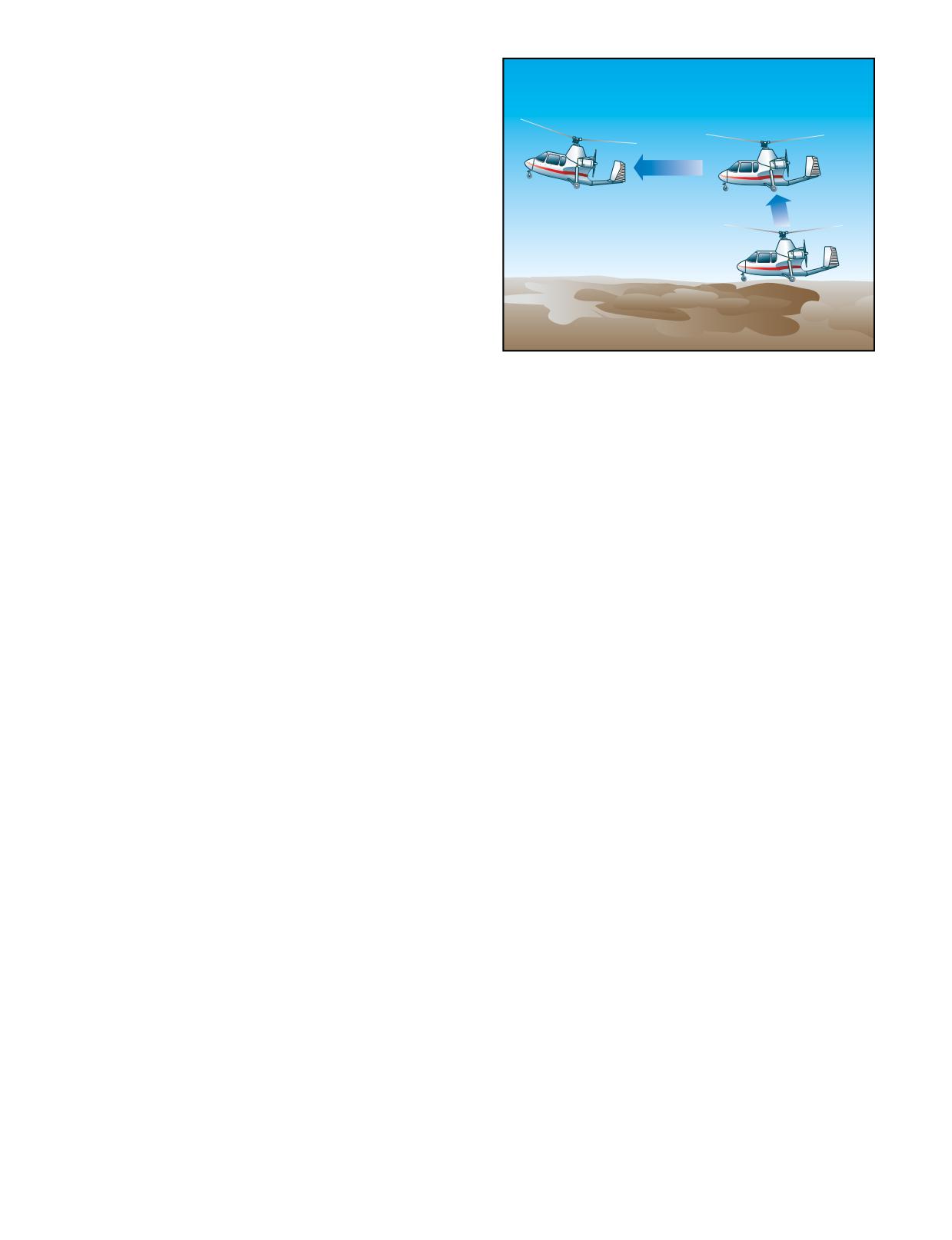
adjust the fuel/air mixture to achieve the best possible
power output. This process is referred to as “leaning
the mixture.” If you are considering a high-altitude
takeoff, and it appears that the climb performance limit
of the gyroplane is being approached, do not attempt a
takeoff until more favorable conditions exist.
SOFT-FIELD TAKEOFF
A soft field may be defined as any takeoff surface that
measurably retards acceleration during the takeoff roll.
The objective of the soft-field takeoff is to transfer the
weight of the aircraft from the landing gear to the rotor
as quickly and smoothly as possible to eliminate the
drag caused by surfaces, such as tall grass, soft dirt, or
snow. This takeoff requires liftoff at a speed just above
the minimum level flight speed for the aircraft. Due to
design, many of the smaller gyroplanes have a limited
Figure 20-5. During a jump takeoff, excess rotor inertia is
used to lift the gyroplane nearly vertical, where it is then
pitch attitude available, as tail contact with the ground
accelerated through minimum level flight speed.
prevents high pitch attitudes until in flight. At mini-
mum level flight speed, the pitch attitude is often such
that the tail wheel is lower than the main wheels. When
performing a soft-field takeoff, these aircraft require
minimum level flight speed. Failure to have sufficient
slightly higher liftoff airspeeds to allow for proper tail
rotor r.p.m. for a jump takeoff results in the gyroplane
clearance.
settling back to the ground. Before attempting a jump
takeoff, it is essential that you first determine if it is
COMMON ERRORS
possible given the existing conditions by consulting the
1.
Failure to check rotor for proper operation, track,
relevant performance chart. Should conditions of
and r.p.m. prior to takeoff.
weight, altitude, temperature, or wind leave the suc-
cessful outcome of the maneuver in doubt, it should not
2.
Improper initial positioning of flight controls.
be attempted.
3.
Improper application of power.
The prudent pilot may also use a “rule of thumb” for
4.
Allowing gyroplane to lose momentum by
predicting performance before attempting a jump take-
slowing or stopping on takeoff surface prior to
off. As an example, suppose that a particular gyroplane
initiating takeoff.
is known to be able to make a jump takeoff and remain
5.
Poor directional control.
airborne to accelerate to VX at a weight of 1,800 pounds
and a density altitude of 2,000 feet. Since few takeoffs
6.
Improper pitch attitude during lift-off.
are made under these exact conditions, compensation
7.
Settling back to takeoff surface after becoming
must be made for variations in weight, wind, and den-
airborne.
sity altitude. The “rule of thumb” being used for this
particular aircraft stipulates that 1,000 feet of density
8.
Failure to establish and maintain proper climb
altitude equates with 10 m.p.h. wind or 100 pounds of
attitude and airspeed.
gross weight. To use this equation, you must first deter-
9.
Drifting from the desired ground track during the
mine the density altitude. This is accomplished by
climb.
setting your altimeter to the standard sea level pressure
setting of 29.92 inches of mercury and reading the pres-
JUMP TAKEOFF
sure altitude. Next, you must correct for nonstandard
Gyroplanes with collective pitch change, and the
temperature. Standard temperature at sea level is 59°F
ability to prerotate the rotor system to speeds approxi-
(15°C) and decreases 3.5°F (2°C) for every additional
mately 50 percent higher than those required for
normal flight, are capable of achieving extremely short
takeoff rolls. Actual jump takeoffs can be performed
under the proper conditions. A jump takeoff requires no
ground roll, making it the most effective soft-field and
crosswind takeoff procedure. [Figure 20-5] A jump
takeoff is possible because the energy stored in the
Density Altitude-Pressure altitude corrected for nonstandard temper-
blades, as a result of the higher rotor r.p.m., is used to
ature. This is a theoretical value that is used in determining aircraft
performance.
keep the gyroplane airborne as it accelerates through
20-5
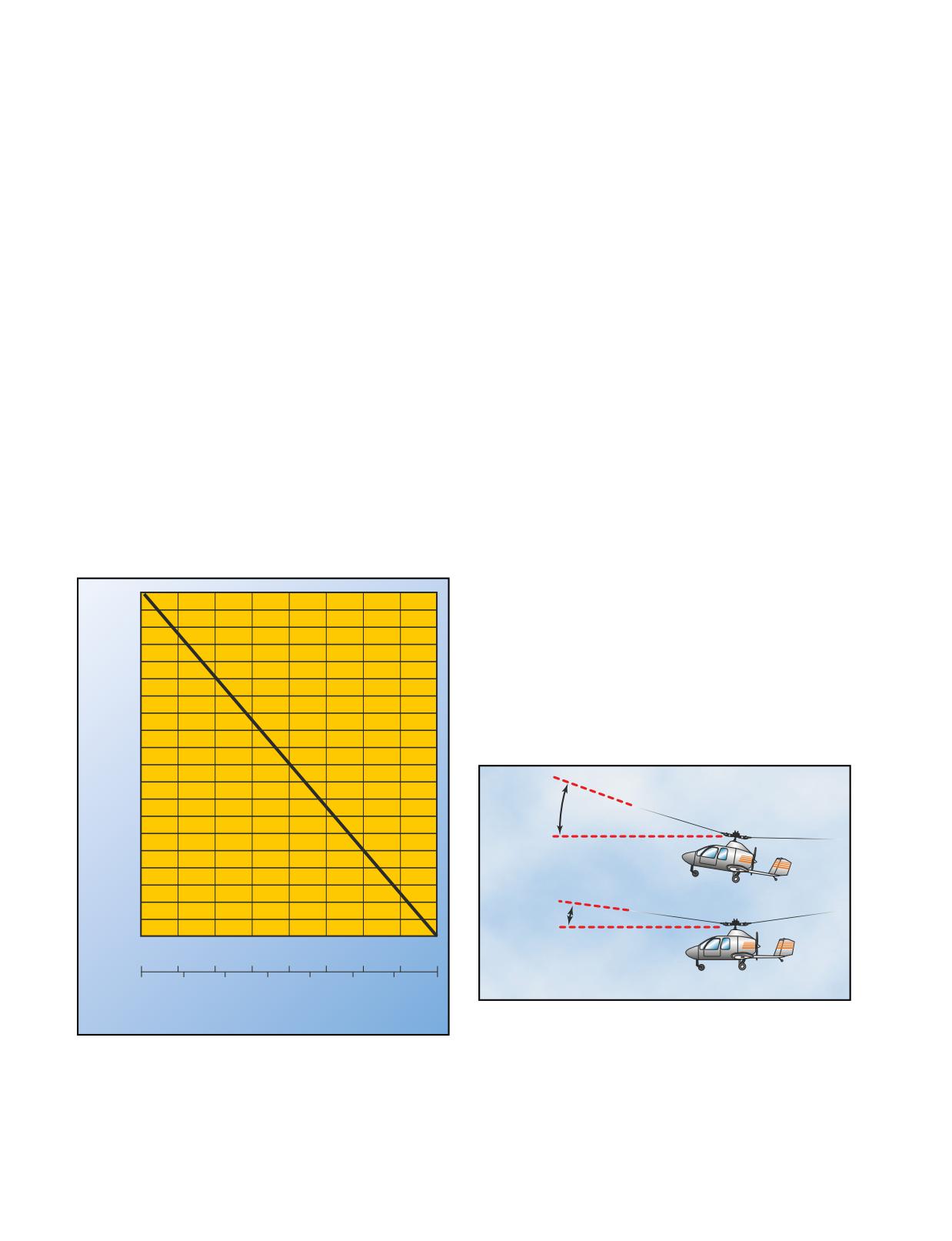
one thousand feet of pressure altitude. [Figure 20-6]
variety in designs, many gyroplanes have only basic
Once you have determined the standard temperature
instruments available, and the pilot is often exposed to
for your pressure altitude, compare it with the actual
the airflow. In addition, the visual clues found on other
existing conditions. For every 10°F (5.5°C) the actual
aircraft, such as cowlings, wings, and windshields
temperature is above standard, add 750 feet to the
might not be part of your gyroplane’s design.
pressure altitude to estimate the density altitude. If the
Therefore, much more reliance is placed on pilot
density altitude is above 2,000 feet, a jump takeoff in
interpretation of flight attitude and the “feel” of the
this aircraft should not be attempted unless wind and/or
gyroplane than in other types of aircraft. Acquiring the
a weight reduction would compensate for the decrease
skills to precisely control a gyroplane can be a
in performance. Using the equation, if the density alti-
challenging and rewarding experience, but requires
tude is 3,000 feet (1,000 feet above a satisfactory jump
dedication and the direction of a competent instructor.
density altitude), a reduction of 100 pounds in gross
weight or a 10 m.p.h. of wind would still allow a satis-
STRAIGHT-AND-LEVEL FLIGHT
factory jump takeoff. Additionally, a reduction of 50
Straight-and-level flight is conducted by maintaining a
pounds in weight combined with a 5 m.p.h. wind would
constant altitude and a constant heading. In flight, a
also allow a satisfactory jump. If it is determined that a
gyroplane essentially acts as a plumb suspended from
jump takeoff should not be conducted because the
the rotor. As such, torque forces from the engine cause
weight cannot be reduced or an appropriate wind is not
the airframe to be deflected a few degrees out of the
blowing, then consideration should be given to a
vertical plane. This very slight “out of vertical”
rolling takeoff. A takeoff roll of 10 m.p.h. is equivalent
condition should be ignored and the aircraft flown to
to a wind speed of 10 m.p.h. or a reduction of 100
maintain a constant heading.
pounds in gross weight. It is important to note that a
jump takeoff is predicated on having achieved a spe-
The throttle is used to control airspeed. In level flight,
cific rotor r.p.m. If this r.p.m. has not been attained,
when the airspeed of a gyroplane increases, the rotor
performance is unpredictable, and the maneuver should
disc angle of attack must be decreased. This causes
not be attempted.
pitch control to become increasingly more sensitive.
[Figure 20-7] As this disc angle becomes very small, it
is possible to overcontrol a gyroplane when encounter-
20,000
ing turbulence. For this reason, when extreme
19,000
turbulence is encountered or expected, airspeed should
18,000
17,000
be decreased. Even in normal conditions, a gyroplane
16,000
requires constant attention to maintain straight-and-
15,000
level flight. Although more stable than helicopters,
14,000
gyroplanes are less stable than airplanes. When cyclic
13,000
trim is available, it should be used to relieve any stick
12,000
forces required during stabilized flight.
11,000
10,000
9,000
8,000
7,000
6,000
5,000
Rotor
4.000
Disk
3,000
Angle
Low Speed
2,000
1,000
Sea Level
-25
-20
-15
-10
-5
°C
0
5
10
15
–12
0
10
20
°F
30
40
50
59
High Speed
Figure 20-7. The angle of the rotor disc decreases at higher
cruise speeds, which increases pitch control sensitivity.
Figure 20-6. Standard temperature chart.
CLIMBS
A climb is achieved by adding power in excess of what
BASIC FLIGHT MANEUVERS
is required for straight-and-level flight at a particular
Conducting flight maneuvers in a gyroplane is differ-
airspeed. The amount of excess power used is directly
ent than in most other aircraft. Because of the wide
proportional to the climb rate. For maneuvers when
20-6
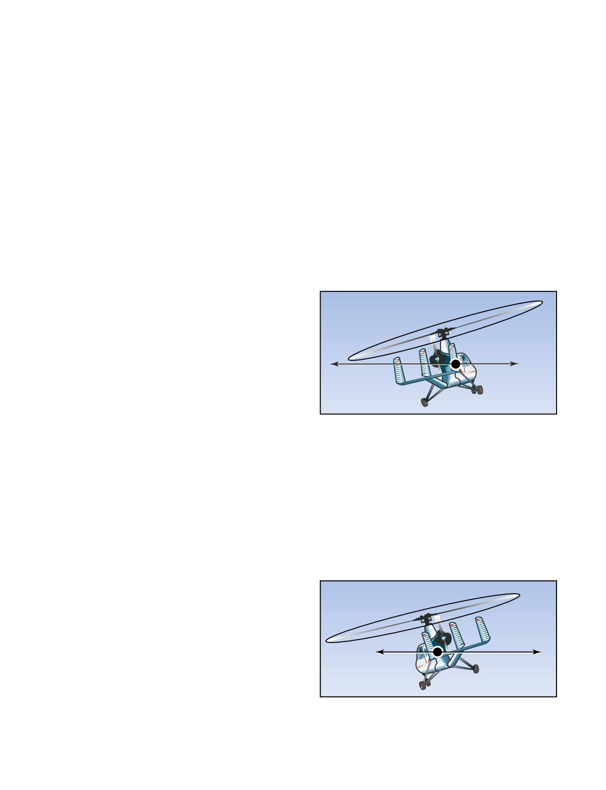
maximum performance is desired, two important climb
The bank angle used for a turn directly affects the rate
speeds are best angle-of-climb speed and best rate-of-
of turn. As the bank is steepened, the turn rate
climb speed.
increases, but more power is required to maintain alti-
tude. A bank angle can be reached where all available
Because a gyroplane cannot be stalled, it may be tempt-
power is required, with any further increase in bank
ing to increase the climb rate by decreasing airspeed.
resulting in a loss of airspeed or altitude. Turns during a
This practice, however, is self-defeating. Operating
climb should be made at the minimum angle of bank
below the best angle-of-climb speed causes a diminish-
necessary, as higher bank angles would require more
ing rate of climb. In fact, if a gyroplane is slowed to the
power that would otherwise be available for the climb.
minimum level flight speed, it requires full power just
Turns while gliding increase the rate of descent and may
to maintain altitude. Operating in this performance
be used as an effective way of losing excess altitude.
realm, sometimes referred to as the “backside of the
power curve,” is desirable in some maneuvers, but can
SLIPS
be hazardous when maximum climb performance is
A slip occurs when the gyroplane slides sideways
required. For further explanation of a gyroplane power
toward the center of the turn. [Figure 20-8] It is caused
curve, see Flight at Slow Airspeeds, which is discussed
by an insufficient amount of rudder pedal in the direc-
later in this chapter.
tion of the turn, or too much in the direction opposite
the turn. In other words, holding improper rudder pedal
DESCENTS
pressure keeps the nose from following the turn, the
A descent is the result of using less power than that
gyroplane slips sideways toward the center of the turn.
required for straight-and-level flight at a particular
airspeed. Varying engine power during a descent allows
Slip
you to choose a variety of descent profiles. In a power-off
descent, the minimum descent rate is achieved by using
the airspeed that would normally be used for level flight
at minimum power, which is also very close to the speed
used for the best angle of climb. When distance is a factor
during a power-off descent, maximum gliding distance
HCL
Inertia
can be achieved by maintaining a speed very close to the
best rate-of-climb airspeed. Because a gyroplane can be
safely flown down to zero airspeed, a common error in
this type of descent is attempting to extend the glide by
Figure 20-8. During a slip, the rate of turn is too slow for the
raising the pitch attitude. The result is a higher rate of
angle of bank used, and the horizontal component of lift
descent and less distance being covered. For this reason,
(HCL) exceeds inertia. You can reestablish equilibrium by
decreasing the angle of bank, increasing the rate of turn by
proper glide speed should be adhered to closely. Should a
applying rudder pedal, or a combination of the two.
strong headwind exist, while attempting to achieve the
maximum distance during a glide, a rule of thumb to
achieve the greatest distance is to increase the glide speed
SKIDS
by approximately 25 percent of the headwind. The atti-
A skid occurs when the gyroplane slides sideways away
tude of the gyroplane for best glide performance is
from the center of the turn. [Figure 20-9] It is caused by
learned with experience, and slight pitch adjustments are
too much rudder pedal pressure in the direction of the
made for the proper airspeed. If a descent is needed to
turn, or by too little in the direction opposite the turn. If
lose excess altitude, slowing the gyroplane to below the
the gyroplane is forced to turn faster with increased
best glide speed increases the rate of descent. Typically,
pedal pressure instead of by increasing the degree of
slowing to zero airspeed results in a descent rate twice
that of maintaining the best glide speed.
Skid
TURNS
Turns are made in a gyroplane by banking the rotor disc
with cyclic control. Once the area, in the direction of the
turn, has been cleared for traffic, apply sideward pres-
HCL
Inertia
sure on the cyclic until the desired bank angle is
achieved. The speed at which the gyroplane enters the
bank is dependent on how far the cyclic is displaced.
When the desired bank angle is reached, return the
Figure 20-9. During a skid, inertia exceeds the HCL. To
cyclic to the neutral position. The rudder pedals are used
reestablish equilibrium, increase the bank angle or reduce
to keep the gyroplane in longitudinal trim throughout
the rate of turn by applying rudder pedal. You may also use a
the turn, but not to assist in establishing the turn.
combination of these two corrections.
20-7
bank, it skids sideways away from the center of the turn
aircraft in the vicinity. Prior to each maneuver, a clear-
instead of flying in its normal curved pattern.
ing turn should be accomplished to ensure the practice
area is free of conflicting traffic.
COMMON ERRORS DURING BASIC FLIGHT
MANEUVERS
RECTANGULAR COURSE
The rectangular course is a training maneuver in which
1.
Improper coordination of flight controls.
the ground track of the gyroplane is equidistant from
2.
Failure to cross-check and correctly interpret
all sides of a selected rectangular area on the ground.
outside and instrument references.
[Figure 20-10] While performing the maneuver, the
altitude and airspeed should be held constant. The rec-
3.
Using faulty trim technique.
tangular course helps you to develop a recognition of a
drift toward or away from a line parallel to the intended
STEEP TURNS
ground track. This is helpful in recognizing drift toward
A steep turn is a performance maneuver used in
or from an airport runway during the various legs of the
training that consists of a turn in either direction at a
airport traffic pattern.
bank angle of approximately 40°. The objective of
performing steep turns is to develop smoothness, coor-
For this maneuver, pick a square or rectangular field, or
dination, orientation, division of attention, and control
an area bounded on four sides by section lines or roads,
techniques.
where the sides are approximately a mile in length. The
Prior to initiating a steep turn, or any other flight
area selected should be well away from other air traf-
maneuver, first complete a clearing turn to check the
fic. Fly the maneuver approximately 600 to 1,000 feet
area for traffic. To accomplish this, you may execute
above the ground, which is the altitude usually required
either one 180° turn or two 90° turns in opposite
for an airport traffic pattern. You should fly the
directions. Once the area has been cleared, roll the
gyroplane parallel to and at a uniform distance, about
gyroplane into a
40° angle-of-bank turn while
one-fourth to one-half mile, from the field boundaries,
smoothly adding power and slowly moving the cyclic
not above the boundaries. For best results, position
aft to maintain altitude. Maintain coordinated flight
your flight path outside the field boundaries just far
with proper rudder pedal pressure. Throughout the turn,
enough away that they may be easily observed. You
cross-reference visual cues outside the gyroplane with
should be able to see the edges of the selected field
the flight instruments, if available, to maintain a con-
while seated in a normal position and looking out the
stant altitude and angle of bank. Anticipate the roll-out
side of the gyroplane during either a left-hand or right-
by leading the roll-out heading by approximately 20°.
hand course. The distance of the ground track from the
Using section lines or prominent landmarks to aid in
edges of the field should be the same regardless of
orientation can be helpful in rolling out on the proper
whether the course is flown to the left or right. All turns
heading. During roll-out, gradually return the cyclic to
should be started when your gyroplane is abeam the
the original position and reduce power to maintain
corners of the field boundaries. The bank normally
altitude and airspeed.
should not exceed 30°.
COMMON ERRORS
Although the rectangular course may be entered from
any direction, this discussion assumes entry on a down-
1.
Improper bank and power coordination during
wind heading. As you approach the field boundary on
entry and rollout.
the downwind leg, you should begin planning for your
2.
Uncoordinated use of flight controls.
turn to the crosswind leg. Since you have a tailwind on
the downwind leg, the gyroplane’s groundspeed is
3.
Exceeding manufacturer’s recommended maxi-
increased (position 1). During the turn onto the cross-
mum bank angle.
wind leg, which is the equivalent of the base leg in a
4.
Improper technique in correcting altitude
traffic pattern, the wind causes the gyroplane to drift
deviations.
away from the field. To counteract this effect, the roll-
in should be made at a fairly fast rate with a relatively
5.
Loss of orientation.
steep bank (position 2).
6.
Excessive deviation from desired heading during
rollout.
As the turn progresses, the tailwind component
decreases, which decreases the groundspeed.
GROUND REFERENCE MANEUVERS
Consequently, the bank angle and rate of turn must be
Ground reference maneuvers are training exercises
reduced gradually to ensure that upon completion of
flown to help you develop a division of attention
the turn, the crosswind ground track continues to be the
between the flight path and ground references, while
same distance from the edge of the field. Upon comple-
controlling the gyroplane and watching for other
tion of the turn, the gyroplane should be level and
20-8
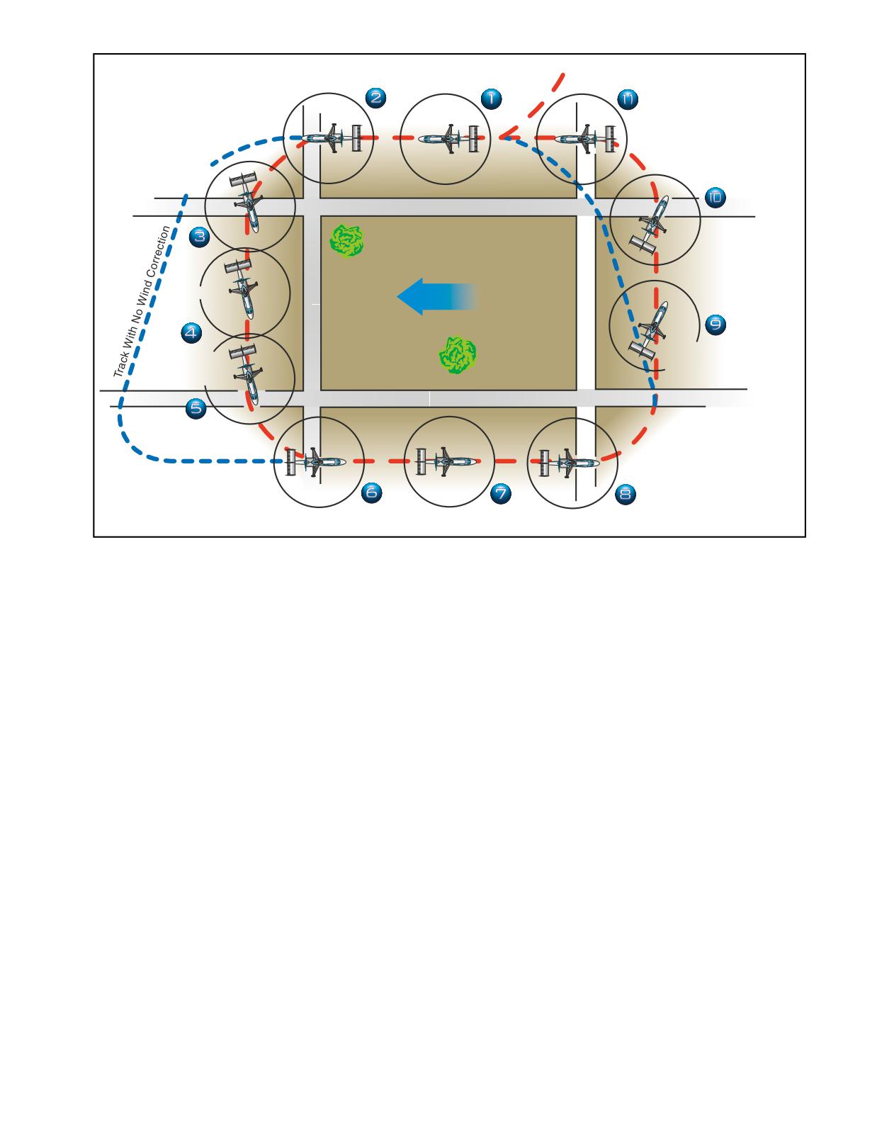
Start Turn
Enter
No Crab
Pattern
At Boundary
Turn More Than
90°-Roll Out
Complete Turn
With Crab Established
At Boundary
Turn More
Complete Turn
Than 90°
At Boundary
Start Turn
At Boundary
Crab Into
Crab Into
WIND
Wind
Wind
Turn less Than
Start Turn
90°-Roll Out
At Boundary
With Crab Established
Complete Turn
Turn Less
At Boundary
Than 90°
Start Turn
At Boundary
Complete Turn
At Boundary
No Crab
Figure 20-10. Rectangular course. The numbered positions in the text refer to the numbers in this illustration.
aligned with the downwind corner of the field.
On the upwind leg, the wind is a headwind, which
However, since the crosswind is now pushing you
results in an decreased groundspeed (position
7).
away from the field, you must establish the proper drift
Consequently, enter the turn onto the next leg with a
correction by flying slightly into the wind. Therefore,
fairly slow rate of roll-in, and a relatively shallow bank
the turn to crosswind should be greater than a 90°
(position 8). As the turn progresses, gradually increase
change in heading (position 3). If the turn has been
the bank angle because the headwind component is
made properly, the field boundary again appears to be
diminishing, resulting in an increasing groundspeed.
one-fourth to one-half mile away. While on the cross-
During and after the turn onto this leg, the wind tends
wind leg, the wind correction should be adjusted, as
to drift the gyroplane toward the field boundary. To
necessary, to maintain a uniform distance from the field
compensate for the drift, the amount of turn must be
boundary (position 4).
less than 90° (position 9).
As the next field boundary is being approached (posi-
Again, the rollout from this turn must be such that as
tion 5), plan the turn onto the upwind leg. Since a wind
the gyroplane becomes level, the nose of the gyroplane
correction angle is being held into the wind and toward
is turned slightly away the field and into the wind to
the field while on the crosswind leg, this next turn
correct for drift. The gyroplane should again be the
requires a turn of less than 90°. Since the crosswind
same distance from the field boundary and at the same
becomes a headwind, causing the groundspeed to
altitude, as on other legs. Continue the crosswind leg
decrease during this turn, the bank initially must be
until the downwind leg boundary is approached (posi-
medium and progressively decreased as the turn pro-
tion 10). Once more you should anticipate drift and
ceeds. To complete the turn, time the rollout so that the
turning radius. Since drift correction was held on the
gyroplane becomes level at a point aligned with the
crosswind leg, it is necessary to turn greater than 90° to
corner of the field just as the longitudinal axis of the
align the gyroplane parallel to the downwind leg
gyroplane again becomes parallel to the field boundary
boundary. Start this turn with a medium bank angle,
(position 6). The distance from the field boundary
gradually increasing it to a steeper bank as the turn pro-
should be the same as on the other sides of the field.
gresses. Time the rollout to assure paralleling the
20-9
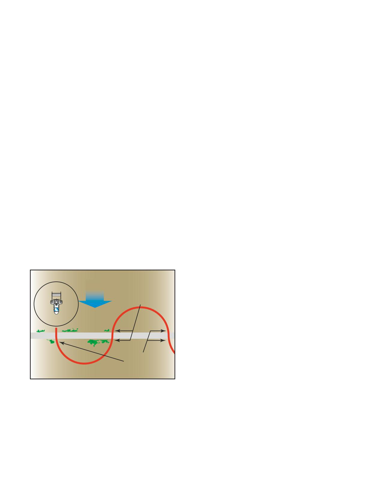
boundary of the field as the gyroplane becomes level
used throughout the maneuver since the gyroplane is
(position 11).
headed directly downwind and the groundspeed is at its
highest. Gradually reduce the bank, as necessary, to
If you have a direct headwind or tailwind on the upwind
describe a ground track of a half circle. Time the turn
and downwind leg, drift should not be encountered.
so that as the rollout is completed, the gyroplane is
However, it may be difficult to find a situation where
crossing the reference line perpendicular to it and head-
the wind is blowing exactly parallel to the field bound-
ing directly upwind. Immediately enter a bank in the
aries. This makes it necessary to use a slight wind
opposite direction to begin the second half of the “S.”
correction angle on all the legs. It is important to antici-
Since the gyroplane is now on an upwind heading, this
pate the turns to compensate for groundspeed, drift, and
bank (and the one just completed before crossing the
turning radius. When the wind is behind the gyroplane,
reference line) is the shallowest in the maneuver.
the turn must be faster and steeper; when it is ahead of
Gradually increase the bank, as necessary, to describe a
the gyroplane, the turn must be slower and shallower.
ground track that is a half circle identical in size to the
These same techniques apply while flying in an airport
one previously completed on the other side of the refer-
traffic pattern.
ence line. The steepest bank in this turn should be
attained just prior to rollout when the gyroplane is
S-TURNS
approaching the reference line nearest the downwind
Another training maneuver you might use is the S-turn,
heading. Time the turn so that as the rollout is com-
which helps you correct for wind drift in turns. This
plete, the gyroplane is perpendicular to the reference
maneuver requires turns to the left and right. The refer-
line and is again heading directly downwind.
ence line used, whether a road, railroad, or fence,
should be straight for a considerable distance and
In summary, the angle of bank required at any given
should extend as nearly perpendicular to the wind as
point in the maneuver is dependent on the ground-
possible.
speed. The faster the groundspeed, the steeper the
bank; the slower the groundspeed, the shallower
The object of S-turns is to fly a pattern of two half
the bank. To express it another way, the more nearly
circles of equal size on opposite sides of the reference
the gyroplane is to a downwind heading, the steeper the
line. [Figure
20-11] The maneuver should be
bank; the more nearly it is to an upwind heading, the
performed at a constant altitude of 600 to 1,000 feet
shallower the bank. In addition to varying the angle of
above the terrain. S-turns may be started at any point;
bank to correct for drift in order to maintain the proper
however, during early training it may be beneficial to
radius of turn, the gyroplane must also be flown with a
start on a downwind heading. Entering downwind
drift correction angle (crab) in relation to its ground
permits the immediate selection of the steepest bank
track; except of course, when it is on direct upwind or
downwind headings or there is no wind. One would
normally think of the fore and aft axis of the gyroplane
as being tangent to the ground track pattern at each
Points of
point. However, this is not the case. During the turn on
WIND
Shallowest Bank
the upwind side of the reference line (side from which
the wind is blowing), crab the nose of the gyroplane
toward the outside of the circle. During the turn on the
downwind side of the reference line (side of the refer-
ence line opposite to the direction from which the wind
is blowing), crab the nose of the gyroplane toward the
inside of the circle. In either case, it is obvious that the
Points of
gyroplane is being crabbed into the wind just as it is
Steepest Bank
when trying to maintain a straight ground track. The
amount of crab depends upon the wind velocity and
how nearly the gyroplane is to a crosswind position.
Figure 20-11. S-turns across a road.
The stronger the wind, the greater the crab angle at any
given position for a turn of a given radius. The more
nearly the gyroplane is to a crosswind position, the
that is desired throughout the maneuver. The discus-
greater the crab angle. The maximum crab angle should
sion that follows is based on choosing a reference line
be at the point of each half circle farthest from the
that is perpendicular to the wind and starting the
reference line.
maneuver on a downwind heading.
A standard radius for S-turns cannot be specified, since
As the gyroplane crosses the reference line, immedi-
the radius depends on the airspeed of the gyroplane, the
ately establish a bank. This initial bank is the steepest
20-10
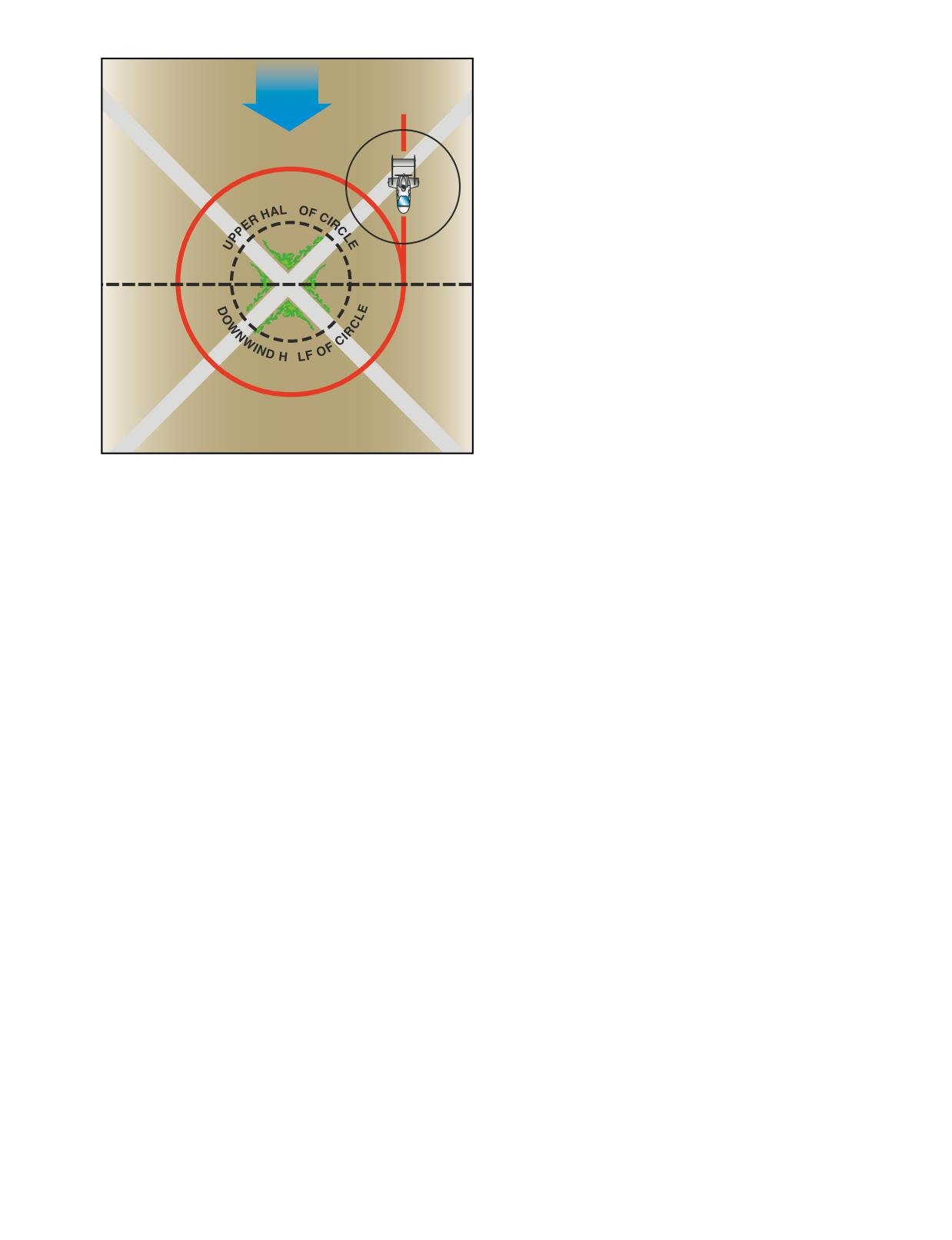
crossroads, or other similar small landmarks are usu-
ally suitable. The point should be in an area away from
WIND
communities, livestock, or groups of people on the
ground to prevent possible annoyance or hazard to
Steeper
others. Since the maneuver is performed between 600
Bank
and 1,000 feet AGL, the area selected should also
afford an opportunity for a safe emergency landing in
the event it becomes necessary.
F
To enter turns around a point, fly the gyroplane on a
downwind heading to one side of the selected point at a
Shallowest
Steepest
distance equal to the desired radius of turn. When any
Bank
Bank
significant wind exists, it is necessary to roll into the
initial bank at a rapid rate so that the steepest bank is
attained abeam the point when the gyroplane is headed
A
directly downwind. By entering the maneuver while
heading directly downwind, the steepest bank can be
attained immediately. Thus, if a bank of 40° is desired,
Shallower
the initial bank is 40° if the gyroplane is at the correct
Bank
distance from the point. Thereafter, the bank is gradu-
ally shallowed until the point is reached where the
Figure 20-12. Turns around a point.
gyroplane is headed directly upwind. At this point, the
bank is gradually steepened until the steepest bank is
again attained when heading downwind at the initial
velocity of the wind, and the initial bank chosen for
point of entry.
entry.
Just as S-turns require that the gyroplane be turned into
TURNS AROUND A POINT
the wind, in addition to varying the bank, so do turns
This training maneuver requires you to fly constant
around a point. During the downwind half of the circle,
radius turns around a preselected point on the ground
the gyroplane’s nose must be progressively turned
using a maximum bank of approximately 40°, while
toward the inside of the circle; during the upwind half,
maintaining a constant altitude. [Figure 20-12] Your
the nose must be progressively turned toward the out-
objective, as in other ground reference maneuvers, is to
side. The downwind half of the turn around the point
develop the ability to subconsciously control the gyro-
may be compared to the downwind side of the S-turn,
plane while dividing attention between the flight path
while the upwind half of the turn around a point may be
and ground references, while still watching for other
compared to the upwind side of the S-turn.
air traffic in the vicinity.
The factors and principles of drift correction that are
As you become experienced in performing turns
involved in S-turns are also applicable in this maneu-
around a point and have a good understanding of the
ver. As in other ground track maneuvers, a constant
effects of wind drift and varying of the bank angle and
radius around a point will, if any wind exists, require a
wind correction angle, as required, entry into the
constantly changing angle of bank and angles of wind
maneuver may be from any point. When entering this
correction. The closer the gyroplane is to a direct
maneuver at any point, the radius of the turn must be
downwind heading where the groundspeed is greatest,
carefully selected, taking into account the wind veloc-
the steeper the bank, and the faster the rate of turn
ity and groundspeed, so that an excessive bank is not
required to establish the proper wind correction angle.
required later on to maintain the proper ground track.
The more nearly it is to a direct upwind heading where
the groundspeed is least, the shallower the bank, and
COMMON ERRORS DURING GROUND
the slower the rate of turn required to establish
REFERENCE MANEUVERS
the proper wind correction angle. It follows then,
1.
Faulty entry technique.
that throughout the maneuver, the bank and rate of
turn must be gradually varied in proportion to the
2.
Poor planning, orientation, or division of
groundspeed.
attention.
3.
Uncoordinated flight control application.
The point selected for turns around a point should be
prominent and easily distinguishable, yet small enough
4.
Improper correction for wind drift.
to present a precise reference. Isolated trees,
20-11
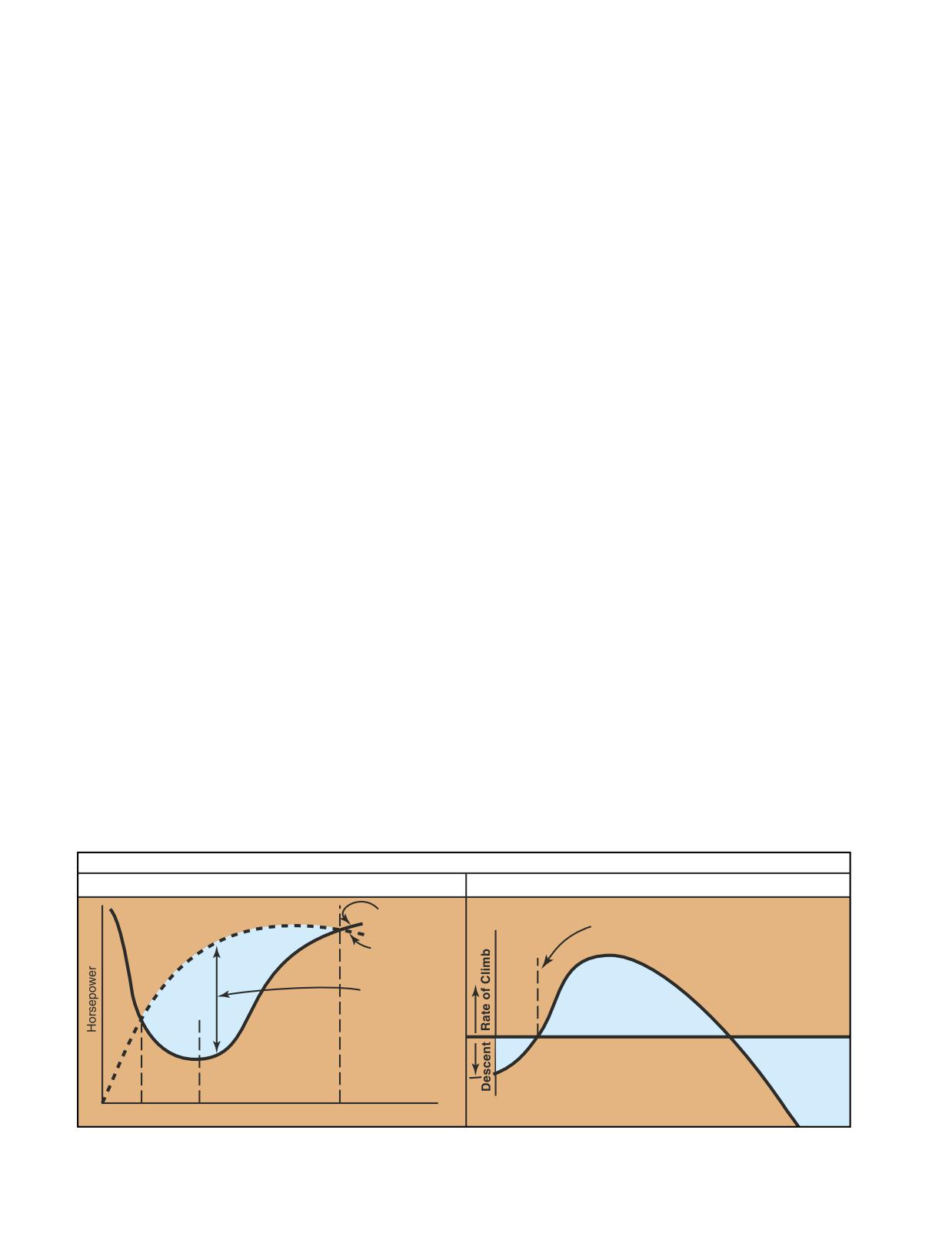
5.
An unsymmetrical ground track during S-turns
hazardous. Should a go-around become necessary,
across a road.
sufficient altitude to regain airspeed and initiate a climb
may not be available, and ground contact may be
6.
Failure to maintain selected altitude or airspeed.
unavoidable.
7.
Selection of a ground reference where there is no
suitable emergency landing site.
Flight at slow airspeeds is usually conducted at air-
speeds 5 to 10 m.p.h. above the minimum level flight
FLIGHT AT SLOW AIRSPEEDS
airspeed. When flying at slow airspeeds, it is important
The purpose of maneuvering during slow flight is to
that your control inputs be smooth and slow to prevent
help you develop a feel for controlling the gyroplane at
a rapid loss of airspeed due to the high drag increases
slow airspeeds, as well as gain an understanding of how
with small changes in pitch attitude. In addition, turns
load factor, pitch attitude, airspeed, and altitude control
should be limited to shallow bank angles. In order to
relate to each other.
prevent losing altitude during turns, power must be
added. Directional control remains very good while
flying at slow airspeeds, because of the high velocity
Like airplanes, gyroplanes have a specific amount of
slipstream produced by the increased engine power.
power that is required for flight at various airspeeds, and
a fixed amount of power available from the engine. This
Recovery to cruise flight speed is made by lowering
data can be charted in a graph format. [Figure 20-13]
the nose and increasing power. When the desired speed
The lowest point of the power required curve represents
is reached, reduce power to the normal cruise power
the speed at which the gyroplane will fly in level flight
setting.
while using the least amount of power. To fly faster than
this speed, or slower, requires more power. While
COMMON ERRORS
practicing slow flight in a gyroplane, you will likely be
operating in the performance realm on the chart that is
1.
Improper entry technique.
left of the minimum power required speed. This is often
2.
Failure to establish and maintain an appropriate
referred to as the “backside of the power curve,” or
airspeed.
flying “behind the power curve.” At these speeds, as
pitch is increased to slow the gyroplane, more and more
3.
Excessive variations of altitude and heading
power is required to maintain level flight. At the point
when a constant altitude and heading are
where maximum power available is being used, no
specified.
further reduction in airspeed is possible without initiat-
4.
Use of too steep a bank angle.
ing a descent. This speed is referred to as the minimum
level flight speed. Because there is no excess power
5.
Rough or uncoordinated control technique.
available for acceleration, recovery from minimum level
flight speed requires lowering the nose of the gyroplane
HIGH RATE OF DESCENT
and using altitude to regain airspeed. For this reason, it is
A gyroplane will descend at a high rate when flown at
essential to practice slow flight at altitudes that allow
very low forward airspeeds. This maneuver may be
sufficient height for a safe recovery. Unintentionally
entered intentionally when a steep descent is desired,
flying a gyroplane on the backside of the power curve
and can be performed with or without power. An unin-
during approach and landing can be extremely
tentional high rate of descent can also occur as a result
TYPICAL GYROPLANE
Power Required & Power Available vs. Airspeed
Rates of Climb & Descent at Full Throttle
Power
Required
Minimum Level Flight Speed
Engine Power
Available at
Full Throttle
Power Available
for Climb and
Acceleration
0
20
45
85
Airspeed, MPH
0
20
40
85 Airspeed, MPH
Figure 20-13. The low point on the power required curve is the speed that the gyroplane can fly while using the least amount of
power, and is also the speed that will result in a minimum sink rate in a power-off glide.
20-12
of failing to monitor and maintain proper airspeed. In
apparent during the sensitive maneuvering required
powered flight, if the gyroplane is flown below mini-
for landing, and care must be taken to avoid overcor-
mum level flight speed, a descent results even though
recting for deviations from the desired approach path.
full engine power is applied. Further reducing the air-
After the turn to final, the approach airspeed appropri-
speed with aft cyclic increases the rate of descent. For
ate for the gyroplane should be established. This speed
gyroplanes with a high thrust-to-weight ratio, this
is normally just below the minimum power required
maneuver creates a very high pitch attitude. To recover,
speed for the gyroplane in level flight. During the
the nose of the gyroplane must lowered slightly to
approach, maintain this airspeed by making adjust-
exchange altitude for an increase in airspeed.
ments to the gyroplane’s pitch attitude, as necessary.
Power is used to control the descent rate.
When operating a gyroplane in an unpowered glide,
slowing to below the best glide speed can also result in
Approximately 10 to 20 feet above the runway, begin
a high rate of descent. As airspeed decreases, the rate of
the flare by gradually increasing back pressure on the
descent increases, reaching the highest rate as forward
cyclic to reduce speed and decrease the rate of descent.
speed approaches zero. At slow airspeeds without the
The gyroplane should reach a near-zero rate of descent
engine running, there is very little airflow over the tail
approximately 1 foot above the runway with the power
surfaces and rudder effectiveness is greatly reduced.
at idle. Low airspeed combined with a minimum of
Rudder pedal inputs must be exaggerated to maintain
propwash over the tail surfaces reduces rudder
effective yaw control. To recover, add power, if avail-
effectiveness during the flare. If a yaw moment is
able, or lower the nose and allow the gyroplane to
encountered, use whatever rudder control is required
accelerate to the proper airspeed. This maneuver
to maintain the desired heading. The gyroplane should
demonstrates the importance of maintaining the proper
be kept laterally level and with the longitudinal axis in
glide speed during an engine-out emergency landing.
the direction of ground track. Landing with sideward
Attempting to stretch the glide by raising the nose
motion can damage the landing gear and must be
results in a higher rate of descent at a lower forward
avoided. In a full-flare landing, attempt to hold the
speed, leaving less distance available for the selection
gyroplane just off the runway by steadily increasing
of a landing site.
back pressure on the cyclic. This causes the gyroplane
to settle slowly to the runway in a slightly nose-high
COMMON ERRORS
attitude as forward momentum dissipates.
1.
Improper entry technique.
Ground roll for a full-flare landing is typically under
2.
Failure to recognize a high rate of descent.
50 feet, and touchdown speed under 20 m.p.h. If a 20
3.
Improper use of controls during recovery.
m.p.h. or greater headwind exists, it may be necessary
to decrease the length of the flare and allow the gyro-
4.
Initiation of recovery below minimum recovery
plane to touch down at a slightly higher airspeed to
altitude.
prevent it from rolling backward on landing. After
touchdown, rotor r.p.m. decays rather rapidly. On
LANDINGS
landings where brakes are required immediately after
Landings may be classified according to the landing
touchdown, apply them lightly, as the rotor is still car-
surface, obstructions, and atmospheric conditions.
rying much of the weight of the aircraft and too much
Each type of landing assumes that certain conditions
braking causes the tires to skid.
exist. To meet the actual conditions, a combination of
techniques may be necessary.
SHORT-FIELD LANDING
A short-field landing is necessary when you have a rel-
NORMAL LANDING
atively short landing area or when an approach must be
The procedure for a normal landing in a gyroplane is
made over obstacles that limit the available landing
predicated on having a prepared landing surface and no
area. When practicing short-field landings, assume you
significant obstructions in the immediate area. After
are making the approach and landing over a 50-foot
entering a traffic pattern that conforms to established
obstruction in the approach area.
standards for the airport and avoids the flow of fixed
wing traffic, a before landing checklist should be
reviewed. The extent of the items on the checklist is
To conduct a short-field approach and landing, fol-
dependent on the complexity of the gyroplane, and can
low normal procedures until you are established on
include fuel, mixture, carburetor heat, propeller, engine
the final approach segment. At this point, use aft
instruments, and a check for traffic.
cyclic to reduce airspeed below the speed for mini-
mum sink. By decreasing speed, sink rate increases
Gyroplanes experience a slight lag between control
and a steeper approach path is achieved, minimizing
input and aircraft response. This lag becomes more
the distance between clearing the obstacle and
20-13
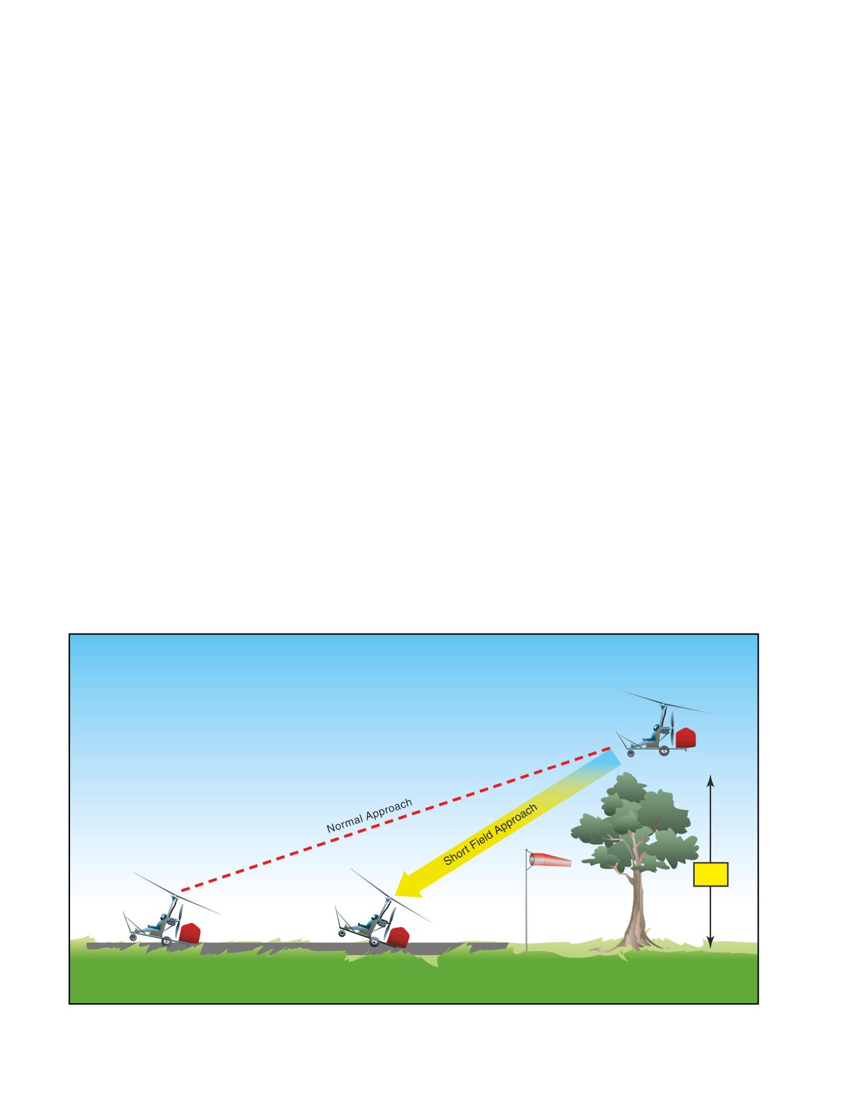
making contact with the surface. [Figure 20-14] The
CROSSWIND LANDING
approach speed must remain fast enough, however,
Crosswind landing technique is normally used in gyro-
to allow the flare to arrest the forward and vertical
planes when a crosswind of approximately 15 m.p.h. or
speed of the gyroplane. If the approach speed is too
less exists. In conditions with higher crosswinds, it
low, the remaining vertical momentum will result in
becomes very difficult, if not impossible, to maintain
a hard landing. On a short-field landing with a slight
adequate compensation for the crosswind. In these con-
headwind, a touchdown with no ground roll is possi-
ditions, the slow touchdown speed of a gyroplane
ble. Without wind, the ground roll is normally less
allows a much safer option of turning directly into the
than 50 feet.
wind and landing with little or no ground roll. Deciding
when to use this technique, however, may be
SOFT-FIELD LANDING
complicated by gusting winds or the characteristics of
Use the soft-field landing technique when the landing
the particular landing area.
surface presents high wheel drag, such as mud, snow,
sand, tall grass or standing water. The objective is to
On final approach, establish a crab angle into the wind
transfer the weight of the gyroplane from the rotor to
to maintain a ground track that is aligned with the
the landing gear as gently and slowly as possible. With
extended centerline of the runway. Just before
a headwind close to the touchdown speed of the
touchdown, remove the crab angle and bank the
gyroplane, a power approach can be made close to the
gyroplane slightly into the wind to prevent drift.
minimum level flight speed. As you increase the nose
Maintain longitudinal alignment with the runway using
pitch attitude just prior to touchdown, add additional
the rudder. In higher crosswinds, if full rudder deflec-
power to cushion the landing. However, power should
tion is not sufficient to maintain alignment with the run-
be removed, just as the wheels are ready to touch. This
way, applying a slight amount of power can increase
results is a very slow, gentle touchdown. In a strong
rudder effectiveness. The length of the flare should be
headwind, avoid allowing the gyroplane to roll rear-
reduced to allow a slightly higher touchdown speed than
ward at touchdown. After touchdown, smoothly and
that used in a no-wind landing. Touchdown is made on
gently lower the nosewheel to the ground. Minimize
the upwind main wheel first, with the other main wheel
the use of brakes, and remain aware that the nosewheel
settling to the runway as forward momentum is lost.
could dig in the soft surface.
After landing, continue to keep the rotor tilted into the
wind to maintain positive control during the rollout.
When no wind exists, use a steep approach similar to a
short-field landing so that the forward speed can be dis-
HIGH-ALTITUDE LANDING
sipated during the flare. Use the throttle to cushion the
A high-altitude landing assumes a density altitude near
touchdown.
the limit of what is considered good climb performance
50'
Figure 20-14. The airspeed used on a short-field approach is slower than that for a normal approach, allowing a steeper
approach path and requiring less runway.
20-14
for the gyroplane. When using the same indicated
to go around. Also, the pitch attitude of the gyroplane
airspeed as that used for a normal approach at lower
in the flare is high enough that the tail would be con-
altitude, a high density altitude results in higher rotor
siderably lower than the main gear, and a touch down
r.p.m. and a slightly higher rate of descent. The greater
with power on would result in a sudden pitch down and
vertical velocity is a result of higher true airspeed as
acceleration of the aircraft. Control of the gyroplane
compared with that at low altitudes. When practicing
under these circumstances may be difficult.
high-altitude landings, it is prudent to first learn normal
Consequently, the decision to go around should be
landings with a flare and roll out. Full flare, no roll
made as early as possible, before the speed is reduced
landings should not be attempted until a good feel for
below the point that power required exceeds power
aircraft response at higher altitudes has been acquired.
available.
As with high-altitude takeoffs, it is also important to
consider the effects of higher altitude on engine
COMMON ERRORS
performance.
1.
Failure to recognize a situation where a go-
around is necessary.
COMMON ERRORS DURING LANDING
2.
Improper application of power.
1.
Failure to establish and maintain a stabilized
approach.
3.
Failure to control pitch attitude.
2.
Improper technique in the use of power.
4.
Failure to maintain recommended airspeeds.
3.
Improper technique during flare or touchdown.
5.
Failure to maintain proper track during climb out.
4.
Touchdown at too low an airspeed with strong
headwinds, causing a rearward roll.
AFTER LANDING AND SECURING
The after-landing checklist should include such items
5.
Poor directional control after touchdown.
as the transponder, cowl flaps, fuel pumps, lights, and
6.
Improper use of brakes.
magneto checks, when so equipped. The rotor blades
demand special consideration after landing, as turning
GO-AROUND
rotor blades can be hazardous to others. Never enter an
The go-around is used to abort a landing approach
area where people or obstructions are present with the
when unsafe factors for landing are recognized. If the
rotor turning. To assist the rotor in slowing, tilt the
decision is made early in the approach to go around,
cyclic control into the prevailing wind or face the gyro-
normal climb procedures utilizing VX and VY should
plane downwind. When slowed to under approximately
be used. A late decision to go around, such as after the
75 r.p.m., the rotor brake may be applied, if available.
full flare has been initiated, may result in an airspeed
Use caution as the rotor slows, as excess taxi speed or
where power required is greater than power available.
high winds could cause blade flap to occur. The blades
When this occurs, a touchdown becomes unavoidable
should be depitched when taxiing if a collective control
and it may be safer to proceed with the landing than to
is available. When leaving the gyroplane, always
sustain an extended ground roll that would be required
secure the blades with a tiedown or rotor brake.
20-15
20-16
Gyroplanes are quite reliable, however emergencies do
safe takeoff, but having this distance available does not
occur, whether a result of mechanical failure or pilot
necessarily guarantee a safe aborted takeoff is possible
error. By having a thorough knowledge of the
for every situation. If the decision to abort is made after
gyroplane and its systems, you will be able to more
liftoff, for example, the gyroplane will require consid-
readily handle the situation. In addition, by knowing
erably more distance to stop than the accelerate/stop
the conditions which can lead to an emergency, many
figure, which only considers the ground roll require-
potential accidents can be avoided.
ment. Planning a course of action for an abort decision
at various stages of the takeoff is the best way to ensure
the gyroplane can be brought safely to a stop should the
ABORTED TAKEOFF
need arise.
Prior to every takeoff, consideration must be given to a
course of action should the takeoff become undesirable
For a gyroplane without a flight manual or other pub-
or unsafe. Mechanical failures, obstructions on the
lished performance data, the accelerate/stop distance
takeoff surface, and changing weather conditions are
can be reasonably estimated once you are familiar with
all factors that could compromise the safety of a take-
the performance and takeoff characteristics of the air-
off and constitute a reason to abort. The decision to
craft. For a more accurate figure, you can accelerate the
abort a takeoff should be definitive and made as soon
gyroplane to takeoff speed, then slow to a stop, and
as an unsafe condition is recognized. By initiating the
note the distance used. Doing this several times gives
abort procedures early, more time and distance will be
you an average accelerate/stop distance. When per-
available to bring the gyroplane to a stop. A late deci-
formance charts for the aircraft are available, as in the
sion to abort, or waiting to see if it will be necessary to
flight manual of a certificated gyroplane, accurate
abort, can result in a dangerous situation with little time
accelerate/stop distances under various conditions can
to respond and very few options available.
be determined by referring to the ground roll informa-
tion contained in the charts.
When initiating the abort sequence prior to the
gyroplane leaving the surface, the procedure is quite
simple. Reduce the throttle to idle and allow the
LIFT-OFF AT LOW AIRSPEED AND
gyroplane to decelerate, while slowly applying aft
HIGH ANGLE OF ATTACK
cyclic for aerodynamic braking. This technique pro-
Because of ground effect, your gyroplane might be able
vides the most effective braking and slows the aircraft
to become airborne at an airspeed less than minimum
very quickly. If the gyroplane has left the surface when
level flight speed. In this situation, the gyroplane is fly-
the decision to abort is made, reduce the throttle until
ing well behind the power curve and at such a high
an appropriate descent rate is achieved. Once contact
angle of attack that unless a correction is made, there
with the surface is made, reduce the throttle to idle and
will be little or no acceleration toward best climb
apply aerodynamic braking as before. The wheel
speed. This condition is often encountered in
brakes, if the gyroplane is so equipped, may be applied,
gyroplanes capable of jump takeoffs. Jumping without
as necessary, to assist in slowing the aircraft.
sufficient rotor inertia to allow enough time to acceler-
ate through minimum level flight speed, usually results
ACCELERATE/STOP DISTANCE
in your gyroplane touching down after liftoff. If you do
An accelerate/stop distance is the length of ground roll
touch down after performing a jump takeoff, you
an aircraft would require to accelerate to takeoff speed
should abort the takeoff.
and, assuming a decision to abort the takeoff is made,
bring the aircraft safely to a stop. This value changes
During a rolling takeoff, if the gyroplane is forced into
for a given aircraft based on atmospheric conditions,
the air too early, you could get into the same situation.
the takeoff surface, aircraft weight, and other factors
It is important to recognize this situation and take
affecting performance. Knowing the accelerate/stop
immediate corrective action. You can either abort the
value for your gyroplane can be helpful in planning a
takeoff, if enough runway exists, or lower the nose and
21-1
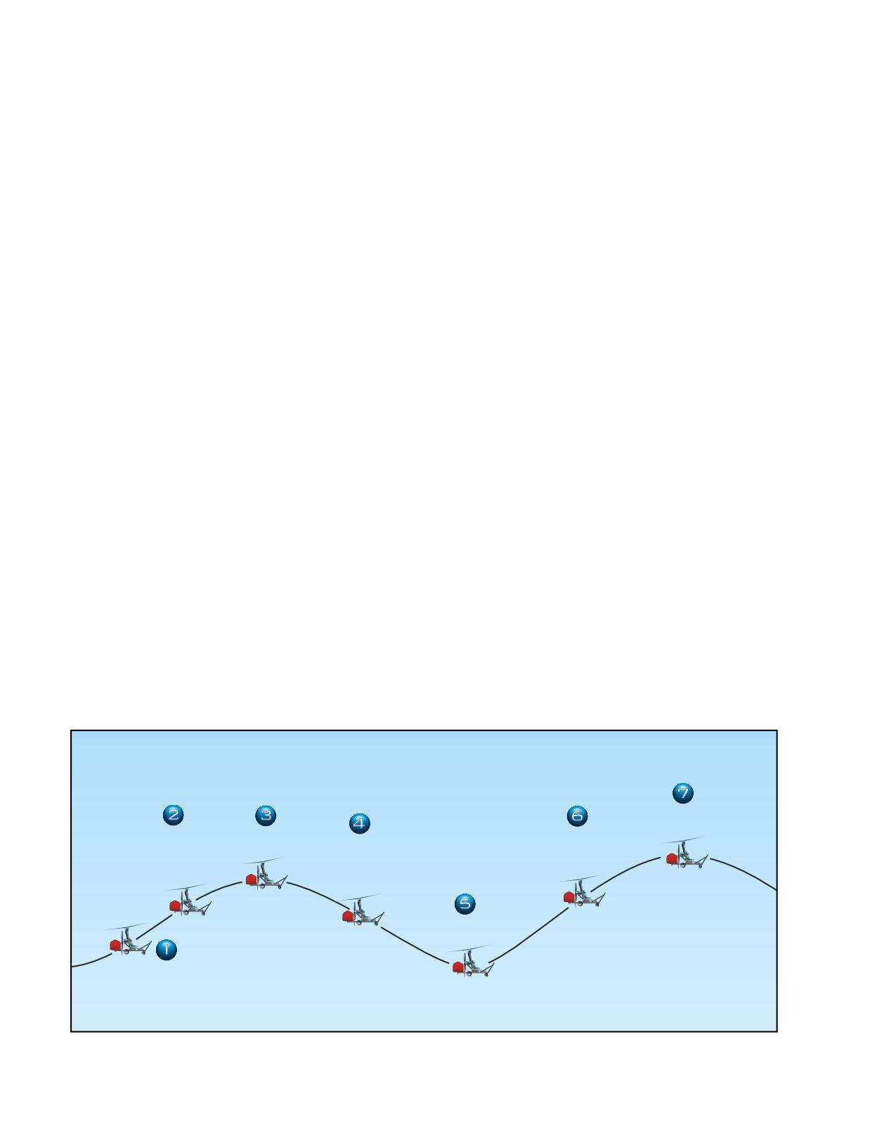
accelerate to the best climb speed. If you choose to con-
As with most other rotor-wing aircraft, gyroplanes
tinue the takeoff, verify that full power is applied, then,
experience a slight delay between control input and the
slowly lower the nose, making sure the gyroplane does
reaction of the aircraft. This delay may cause an inex-
not contact the surface. While in ground effect, acceler-
perienced pilot to apply more control input than
ate to the best climb speed. Then, adjust the nose pitch
required, causing a greater aircraft response than was
attitude to maintain that airspeed.
desired. Once the error has been recognized, opposite
control input is applied to correct the flight attitude.
COMMON ERRORS
Because of the nature of the delay in aircraft response,
The following errors might occur when practicing a
it is possible for the corrections to be out of synchro-
lift-off at a low airspeed.
nization with the movements of the aircraft and aggra-
vate the undesired changes in attitude. The result is
1.
Failure to check rotor for proper operation, track,
PIO, or unintentional oscillations that can grow rapidly
and r.p.m. prior to initiating takeoff.
in magnitude. [Figure 21-1]
2.
Use of a power setting that does not simulate a
“behind the power curve” situation.
In gyroplanes with an open cockpit and limited flight
instruments, it can be difficult for an inexperienced
3.
Poor directional control.
pilot to recognize a level flight attitude due to the lack
4.
Rotation at a speed that is inappropriate for the
of visual references. As a result, PIO can develop as the
maneuver.
pilot chases a level flight attitude and introduces climb-
ing and descending oscillations. PIO can also develop
5.
Poor judgement in determining whether to abort
if a wind gust displaces the aircraft, and the control
or continue takeoff.
inputs made to correct the attitude are out of phase with
6.
Failure to establish and maintain proper climb
the aircraft movements. Because the rotor disc angle
attitude and airspeed, if takeoff is continued.
decreases at higher speeds and cyclic control becomes
more sensitive, PIO is more likely to occur and can be
7.
Not maintaining the desired ground track during
more pronounced at high airspeeds. To minimize the
the climb.
possibility of PIO, avoid high-speed flight in gusty
conditions, and make only small control inputs. After
PILOT-INDUCED OSCILLATION (PIO)
making a control input, wait briefly and observe the
Pilot-induced oscillation, sometimes referred to as por-
reaction of the aircraft before making another input. If
poising, is an unintentional up-and-down oscillation of
PIO is encountered, reduce power and place the cyclic
the gyroplane accompanied with alternating climbs and
in the position for a normal climb. Once the oscillations
descents of the aircraft. PIO is often the result of an
have stopped, slowly return the throttle and cyclic to
inexperienced pilot overcontrolling the gyroplane, but
their normal positions. The likelihood of encountering
this condition can also be induced by gusty wind con-
PIO decreases greatly as experience is gained, and the
ditions. While this condition is usually thought of as a
ability to subconsciously anticipate the reactions of the
longitudinal problem, it can also happen laterally.
gyroplane to control inputs is developed.
Gyroplane
reacts
Variance from desired
Gyroplane
Overcorrection recognized,
Overcorrection
flight path recognized,
reacts
larger input control made
recognized, larger
control input made
to correct
control input made
to correct
to correct
Gyroplane
reacts
Normal
Flight
Figure 21-1. Pilot-induced oscillation can result if the gyroplane’s reactions to control inputs are not anticipated and become
out of phase.
21-2
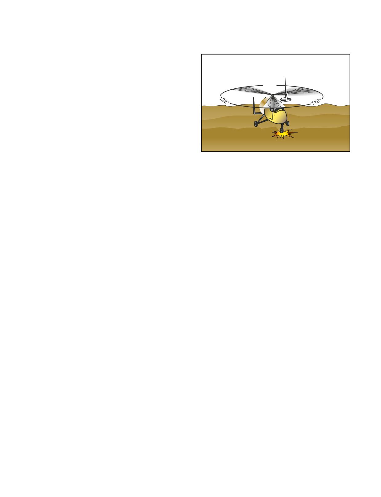
imbalance causing the rotor center of gravity to rotate
BUNTOVER (POWER PUSHOVER)
around the hub. This phenomenon is not unlike an out-
As you learned in Chapter
16-Gyroplane
of-balance washing machine. [Figure 21-2]
Aerodynamics, the stability of a gyroplane is greatly
influenced by rotor force. If rotor force is rapidly
removed, some gyroplanes have a tendency to pitch
forward abruptly. This is often referred to as a forward
Rotor
Center of Gravity
tumble, buntover, or power pushover. Removing the
rotor force is often referred to as unloading the rotor,
122°
and can occur if pilot-induced oscillations become
excessive, if extremely turbulent conditions are
encountered, or the nose of the gyroplane is pushed for-
ward rapidly after a steep climb.
A power pushover can occur on some gyroplanes that
have the propeller thrust line above the center of grav-
ity and do not have an adequate horizontal stabilizer. In
this case, when the rotor is unloaded, the propeller
Figure 21-2. Taxiing on rough terrain can send a shock wave
thrust magnifies the pitching moment around the center
to the rotor system, resulting in the blades of a three-bladed
of gravity. Unless a correction is made, this nose
rotor system moving from their normal 120° relationship to
pitching action could become self-sustaining and
each other.
irreversible. An adequate horizontal stabilizer slows the
pitching rate and allows time for recovery.
To reduce the chance of experiencing ground reso-
Since there is some disagreement between manufactur-
nance, every preflight should include a check for
ers as to the proper recovery procedure for this
proper strut inflation, tire pressure, and lag-lead
situation, you must check with the manufacturer of
damper operation. Improper strut or tire inflation can
your gyroplane. In most cases, you need to remove
change the vibration frequency of the airframe, while
power and load the rotor blades. Some manufacturers,
improper damper settings change the vibration fre-
especially those with gyroplanes where the propeller
quency of the rotor.
thrust line is above the center of gravity, recommend that
you need to immediately remove power in order to pre-
If you experience ground resonance, and the rotor
vent a power pushover situation. Other manufacturers
r.p.m. is not yet sufficient for flight, apply the rotor
recommend that you first try to load the rotor blades. For
brake to maximum and stop the rotor as soon as possi-
the proper positioning of the cyclic when loading up the
ble. If ground resonance occurs during takeoff, when
rotor blades, check with the manufacturer.
rotor r.p.m. is sufficient for flight, lift off immediately.
Ground resonance cannot occur in flight, and the rotor
When compared to other aircraft, the gyroplane is just
blades will automatically realign themselves once the
as safe and very reliable. The most important factor, as
gyroplane is airborne. When prerotating the rotor sys-
in all aircraft, is pilot proficiency. Proper training and
tem prior to takeoff, a slight vibration may be felt that
flight experience helps prevent the risks associated
is a very mild form of ground resonance. Should this
with pilot-induced oscillation or buntover.
oscillation amplify, discontinue the prerotation and
apply maximum rotor brake.
GROUND RESONANCE
Ground resonance is a potentially damaging aerody-
EMERGENCY APPROACH AND
namic phenomenon associated with articulated rotor
LANDING
systems. It develops when the rotor blades move out of
The modern engines used for powering gyroplanes are
phase with each other and cause the rotor disc to
generally very reliable, and an actual mechanical mal-
become unbalanced. If not corrected, ground resonance
function forcing a landing is not a common occurrence.
can cause serious damage in a matter of seconds.
Failures are possible, which necessitates planning for
and practicing emergency approaches and landings.
Ground resonance can only occur while the gyroplane
The best way to ensure that important items are not
is on the ground. If a shock is transmitted to the rotor
overlooked during an emergency procedure is to use a
system, such as with a hard landing on one gear or
checklist, if one is available and time permits. Most
when operating on rough terrain, one or more of the
gyroplanes do not have complex electrical, hydraulic,
blades could lag or lead and allow the rotor system’s
or pneumatic systems that require lengthy checklists.
center of gravity to be displaced from the center of rota-
In these aircraft, the checklist can be easily committed
tion. Subsequent shocks to the other gear aggravate the
to memory so that immediate action can be taken if
21-3
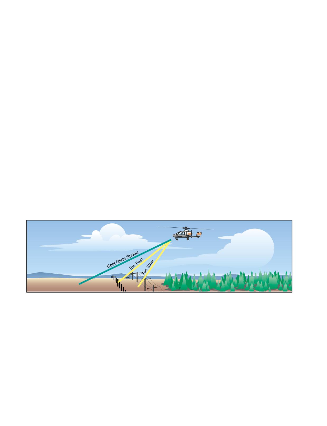
needed. In addition, you should always maintain an
smaller area than would normally be considered. On
awareness of your surroundings and be constantly on
landing, use short or soft field technique, as appropri-
the alert for suitable emergency landing sites.
ate, for the site selected. A slightly higher-than-normal
approach airspeed may be required to maintain ade-
When an engine failure occurs at altitude, the first
quate airflow over the rudder for proper yaw control.
course of action is to adjust the gyroplane’s pitch atti-
tude to achieve the best glide speed. This yields the
EMERGENCY EQUIPMENT AND
most distance available for a given altitude, which in
SURVIVAL GEAR
turn, allows for more possible landing sites. A common
On any flight not in the vicinity of an airport, it is
mistake when learning emergency procedures is
highly advisable to prepare a survival kit with items
attempting to stretch the glide by raising the nose,
that would be necessary in the event of an emergency.
which instead results in a steep approach path at a slow
A properly equipped survival kit should be able to
airspeed and a high rate of descent. [Figure 21-3] Once
provide you with sustenance, shelter, medical care, and
you have attained best glide speed, scan the area within
a means to summon help without a great deal of effort
gliding distance for a suitable landing site. Remember
on your part. An efficient way to organize your survival
to look behind the aircraft, as well as in front, making
kit is to prepare a basic core of supplies that would be
gentle turns, if necessary, to see around the airframe.
necessary for any emergency, and allow additional
When selecting a landing site, you must consider the
space for supplementary items appropriate for the
wind direction and speed, the size of the landing site,
terrain and weather you expect for a particular flight.
obstructions to the approach, and the condition of the
The basic items to form the basis of your survival kit
surface. A site that allows a landing into the wind and
would typically include: a first-aid kit and field
has a firm, smooth surface with no obstructions is the
medical guide, a flashlight, water, a knife, matches,
most desirable. When considering landing on a road, be
some type of shelter, and a signaling device. Additional
alert for powerlines, signs, and automobile traffic. In
items that may be added to meet the conditions, for
many cases, an ideal site will not be available, and it
example, would be a lifevest for a flight over water, or
will be necessary for you to evaluate your options and
heavy clothing for a flight into cold weather. Another
choose the best alternative. For example, if a steady
consideration is carrying a cellular phone. Several
wind will allow a touchdown with no ground roll, it
pilots have been rescued after calling someone to
may be acceptable to land in a softer field or in a
indicate there had been an accident.
Figure 21-3. Any deviation from best glide speed will reduce the distance you can glide and may cause you to land short of a
safe touchdown point.
21-4
As with any aircraft, the ability to pilot a gyroplane
assembled at home. This makes the airworthiness of
safely is largely dependent on the capacity of the pilot
these gyroplanes ultimately dependent on the vigilance
to make sound and informed decisions. To this end,
of the one assembling and maintaining the aircraft.
techniques have been developed to ensure that a pilot
Consider the following scenario.
uses a systematic approach to making decisions, and
that the course of action selected is the most appropri-
Jerry recently attended an airshow that had a gyro-
ate for the situation. In addition, it is essential that you
plane flight demonstration and a number of gyroplanes
learn to evaluate your own fitness, just as you evaluate
on display. Being somewhat mechanically inclined and
the airworthiness of your aircraft, to ensure that your
retired with available spare time, Jerry decided that
physical and mental condition is compatible with a safe
building a gyroplane would be an excellent project for
flight. The techniques for acquiring these essential
him and ordered a kit that day. When the kit arrived,
skills are explained in depth in Chapter
14-
Jerry unpacked it in his garage and immediately began
Aeronautical Decision Making (Helicopter).
the assembly. As the gyroplane neared completion,
Jerry grew more excited at the prospect of flying an air-
As explained in Chapter 14, one of the best methods to
craft that he had built with his own hands. When the
develop your aeronautical decision making is learning
gyroplane was nearly complete, Jerry noticed that a
to recognize the five hazardous attitudes, and how to
rudder cable was missing from the kit, or perhaps lost
counteract these attitudes. [Figure 22-1] This chapter
during the assembly. Rather than contacting the manu-
focuses on some examples of how these hazardous atti-
facturer and ordering a replacement, which Jerry
tudes can apply to gyroplane operations.
thought would be a hassle and too time consuming, he
went to his local hardware store and purchased some
HAZARDOUS ATTITUDE
ANTIDOTE
cable he thought would work. Upon returning home, he
was able to fashion a rudder cable that seemed func-
Impulsivity:
tional and continued with the assembly.
"Do something-quickly!"
"Not so fast. Think first."
Invulnerability:
Jerry is exhibiting “impulsivity.” Rather than taking the
"It won't happen to me!"
"It could happen to me."
time to properly build his gyroplane to the specifica-
Macho:
tions set forth by the manufacturer, Jerry let his
"I can do it."
"Taking chances is foolish."
excitement allow him to cut corners by acting on
impulse, rather than taking the time to think the matter
Resignation:
"I'm not helpless. I can make the
through. Although some enthusiasm is normal during
"What's the use?"
difference."
assembly, it should not be permitted to compromise the
airworthiness of the aircraft. Manufacturers often use
Anti-authority:
"Follow the rules. They are
high quality components, which are constructed and
"Don't tell me!"
usually right."
tested to standards much higher than those found in
hardware stores. This is particularly true in the area of
Figure 22-1. To overcome hazardous attitudes, you must
cables, bolts, nuts, and other types of fasteners where
memorize the antidotes for each of them. You should know
strength is essential. The proper course of action Jerry
them so well that they will automatically come to mind when
should have taken would be to stop, think, and consider
you need them.
the possible consequences of making an impulsive
decision. Had he realized that a broken
IMPULSIVITY
rudder cable in flight could cause a loss of control of
Gyroplanes are a class of aircraft which can be acquired,
the gyroplane, he likely would have taken the time to
constructed, and operated in ways unlike most other air-
contact the manufacturer and order a cable that met the
craft. This inspires some of the most exciting and
design specifications.
rewarding aspects of flying, but it also creates a unique
set of dangers to which a gyroplane pilot must be alert.
INVULNERABILITY
For example, a wide variety of amateur-built gyroplanes
Another area that can often lead to trouble for a gyro-
are available, which can be purchased in kit form and
plane pilots is the failure to obtain adequate flight
22-1
instruction to operate their gyroplane safely. This can
tempted to operate progressively closer to the edge of
be the result of people thinking that because they can
the safe operating envelope. Consider the following
build the machine themselves, it must be simple
scenario.
enough to learn how to fly by themselves. Other
reasons that can lead to this problem can be simply
Pat has been flying gyroplanes for years and has an
monetary, in not wanting to pay the money for adequate
excellent reputation as a skilled pilot. He has recently
instruction, or feeling that because they are qualified in
built a high performance gyroplane with an advanced
another type of aircraft, flight instruction is not neces-
rotor system. Pat was excited to move into a more
sary. In reality, gyroplane operations are quite unique,
advanced aircraft because he had seen the same design
and there is no substitute for adequate training by a
performing aerobatics in an airshow earlier that year.
competent and authorized instructor. Consider the
He was amazed by the capability of the machine. He
following scenario.
had always felt that his ability surpassed the capability
of the aircraft he was flying. He had invested a large
amount of time and resources into the construction of
Jim recently met a coworker who is a certified pilot and
the aircraft, and, as he neared completion of the assem-
owner of a two-seat gyroplane. In discussing the gyro-
bly, he was excited about the opportunity of showing
plane with his coworker, Jim was fascinated and
his friends and family his capabilities.
reminded of his days in the military as a helicopter
pilot many years earlier. When offered a ride, Jim read-
During the first few flights, Pat was not completely
ily accepted. He met his coworker at the airport the
comfortable in the new aircraft, but he felt that he was
following weekend for a short flight and was immedi-
progressing through the transition at a much faster
ately hooked. After spending several weeks researching
pace than the average pilot. One morning, when he was
available designs, Jim decided on a particular
with some of his fellow gyroplane enthusiasts, Pat
gyroplane and purchased a kit. He had it assembled in
began to brag about the superior handling qualities of
a few months, with the help and advice of his new friend
the machine he had built. His friends were very excited,
and fellow gyroplane enthusiast. When the gyroplane
and Pat realized that they would be expecting quite a
was finally finished, Jim asked his friend to take him
show on his next flight. Not wanting to disappoint them,
for a ride in his two-seater to teach him the basics of
he decided that although it might be early, he would
flying. The rest, he said, he would figure out while
give the spectators on the ground a real show. On his
flying his own machine from a landing strip that he had
first pass he came down fairly steep and fast and recov-
fashioned in a field behind his house.
ered from the dive with ease. Pat then decided to make
another pass only this time he would come in much
Jim is unknowingly inviting disaster by allowing him-
steeper. As he began to recover, the aircraft did not
self to be influenced by the hazardous attitude of
climb as he expected and almost settled to the ground.
“invulnerability.” Jim does not feel that it is possible to
Pat narrowly escaped hitting the spectators as he was
have an accident, probably because of his past experi-
trying to recover from the dive.
ence in helicopters and from witnessing the ease with
which his coworker controlled the gyroplane on their
Pat had let the “macho” hazardous attitude influence
flight together. What Jim is failing to consider, how-
his decision making. He could have avoided the conse-
ever, is the amount of time that has passed since he was
quences of this attitude if he had stopped to think that
proficient in helicopters, and the significant differences
taking chances is foolish.
between helicopter and gyroplane operations. He is
also overlooking the fact that his friend is a certificated
RESIGNATION
pilot, who has taken a considerable amount of instruc-
Some of the elements pilots face cannot be controlled.
tion to reach his level of competence. Without adequate
Although we cannot control the weather, we do have
instruction and experience, Jim could, for example,
some very good tools to help predict what it will do,
find himself in a pilot-induced oscillation without
and how it can affect our ability to fly safely. Good
knowing the proper technique for recovery, which
pilots always make decisions that will keep their
could ultimately be disastrous. The antidote for an
options open if an unexpected event occurs while
attitude of invulnerability is to realize that accidents
flying. One of the greatest resources we have in the
can happen to anyone.
cockpit is the ability to improvise and improve the
overall situation even when a risk element jeopardizes
MACHO
the probability of a successful flight. Consider the fol-
Due to their unique design, gyroplanes are quite
lowing scenario.
responsive and have distinct capabilities. Although
gyroplanes are capable of incredible maneuvers, they
Judi flies her gyroplane out of a small grass strip on
do have limitations. As gyroplane pilots grow more
her family’s ranch. Although the rugged landscape of
comfortable with their machines, they might be
the ranch lends itself to the remarkable scenery, it
22-2
leaves few places to safely land in the event of an emer-
regulations, or on the ragged edge, eventually get
gency. The only suitable place to land other than the
caught, or even worse, they end up having an accident.
grass strip is to the west on a smooth section of the road
Consider the following scenario.
leading to the house. During Judi’s training, her traffic
patterns were always made with left turns. Figuring
Dick is planning to fly the following morning and real-
this was how she was to make all traffic patterns, she
izes that his medical certificate has expired. He knows
applied this to the grass strip at the ranch. In addition,
that he will not have time to take a flight physical
she was uncomfortable with making turns to the right.
before his morning flight. Dick thinks to himself “The
Since, the wind at the ranch was predominately from
rules are too restrictive. Why should I spend the time
the south, this meant that the traffic pattern was to the
and money on a physical when I will be the only one at
east of the strip.
risk if I fly tomorrow?”
Judi’s hazardous attitude is “resignation.” She has
Dick decides to fly the next morning thinking that no
accepted the fact that her only course of action is to fly
harm will come as long as no one finds out that he is
east of the strip, and if an emergency happens, there is
flying illegally. He pulls his gyroplane out from the
not much she can do about it. The antidote to this
hangar, does the preflight inspection, and is getting
hazardous attitude is “I’m not helpless, I can make a dif-
ready to start the engine when an FAA inspector walks
ference.” Judi could easily modify her traffic pattern so
up and greets him. The FAA inspector is conducting a
that she is always within gliding distance of a
random inspection and asks to see Dick’s pilot and
suitable landing area. In addition, if she was uncomfort-
medical certificates.
able with a maneuver, she could get additional training.
Dick subjected himself to the hazardous attitude of “anti-
ANTI-AUTHORITY
authority.” Now, he will be unable to fly, and has invited
Regulations are implemented to protect aviation
an exhaustive review of his operation by the FAA. Dick
personnel as well as the people who are not involved in
could have prevented this event if had taken the time to
aviation. Pilots who choose to operate outside of the
think, “Follow the rules. They are usually right.”
22-3
22-4
GLOSSARY
ABSOLUTE ALTITUDE-The act-
ANGLE OF ATTACK-The angle
BLADE FLAP-The ability of the
ual distance an object is above the
between the airfoil’s chord line and
rotor blade to move in a vertical direc-
ground.
the relative wind.
tion. Blades may flap independently
or in unison.
ADVANCING BLADE-The blade
ANTITORQUE PEDAL-The pedal
moving in the same direction as the
used to control the pitch of the tail
BLADE GRIP-The part of the hub
helicopter or gyroplane. In rotorcraft
rotor or air diffuser in a NOTAR®
assembly to which the rotor blades are
that have counterclockwise main rotor
system.
attached, sometimes referred to as
blade rotation as viewed from above,
blade forks.
the advancing blade is in the right half
ANTITORQUE ROTOR-See tail
of the rotor disc area during forward
BLADE LEAD OR LAG-The fore
rotor.
movement.
and aft movement of the blade in the
plane of rotation. It is sometimes
ARTICULATED ROTOR-A rotor
called hunting or dragging.
AIRFOIL-Any surface designed to
system in which each of the blades is
obtain a useful reaction of lift, or neg-
connected to the rotor hub in such a
BLADE LOADING-The load
ative lift, as it moves through the air.
way that it is free to change its pitch
imposed on rotor blades, determined
angle, and move up and down and
by dividing the total weight of the hel-
AGONIC LINE-A line along which
fore and aft in its plane of rotation.
icopter by the combined area of all the
there is no magnetic variation.
rotor blades.
AUTOPILOT-Those units and
AIR DENSITY-The density of the
components that furnish a means of
BLADE ROOT-The part of the
air in terms of mass per unit volume.
automatically controlling the aircraft.
blade that attaches to the blade grip.
Dense air has more molecules per unit
volume than less dense air. The densi-
AUTOROTATION-The condition
BLADE SPAN-The length of a
ty of air decreases with altitude above
of flight during which the main rotor
blade from its tip to its root.
the surface of the earth and with
is driven only by aerodynamic forces
increasing temperature.
with no power from the engine.
BLADE STALL-The condition of
the rotor blade when it is operating at
AIRCRAFT PITCH-When refer-
AXIS-OF-ROTATION-The imagi-
an angle of attack greater than the
enced to an aircraft, it is the move-
nary line about which the rotor
maximum angle of lift.
ment about its lateral, or pitch axis.
rotates. It is represented by a line
Movement of the cyclic forward or aft
drawn through the center of, and per-
BLADE TIP-The further most part
causes the nose of the helicopter or
pendicular to, the tip-path plane.
of the blade from the hub of the rotor.
gyroplane to pitch up or down.
BASIC EMPTY WEIGHT-The
BLADE TRACK-The relationship
AIRCRAFT ROLL-Is the move-
weight of the standard rotorcraft,
of the blade tips in the plane of rota-
ment of the aircraft about its
operational equipment, unusable fuel,
tion. Blades that are in track will move
longitudinal axis. Movement of the
and full operating fluids, including
through the same plane of rotation.
cyclic right or left causes the helicop-
full engine oil.
ter or gyroplane to tilt in that direction.
BLADE TRACKING-The mechan-
BLADE CONING-An upward
ical procedure used to bring the blades
AIRWORTHINESS DIRECTIVE
sweep of rotor blades as a result of lift
of the rotor into a satisfactory relation-
-When an unsafe condition exists
and centrifugal force.
ship with each other under dynamic
with an aircraft, the FAA issues an air-
conditions so that all blades rotate on a
worthiness directive to notify con-
BLADE DAMPER-A device
common plane.
cerned parties of the condition and to
attached to the drag hinge to restrain
describe the appropriate corrective
the fore and aft movement of the rotor
BLADE TWIST-The variation in
action.
blade.
the angle of incidence of a blade
between the root and the tip.
ALTIMETER-An instrument that
BLADE FEATHER OR FEATH-
indicates flight altitude by sensing
ERING-The rotation of the blade
BLOWBACK-The tendency of the
pressure changes and displaying alti-
around the spanwise (pitch change)
rotor disc to tilt aft in forward flight as
tude in feet or meters.
axis.
a result of flapping.
G-1
BUNTOVER-The tendency of a
COLLECTIVE PITCH CON-
DISC AREA-The area swept by the
gyroplane to pitch forward when rotor
TROL-The control for changing the
blades of the rotor. It is a circle with
force is removed.
pitch of all the rotor blades in the main
its center at the hub and has a radius of
rotor system equally and simultane-
one blade length.
CALIBRATED AIRSPEED (CAS)
ously and, consequently, the amount
-Indicated airspeed of an aircraft,
of lift or thrust being generated.
DISC LOADING-The total heli-
corrected for installation and instru-
copter weight divided by the rotor disc
mentation errors.
CONING-See blade coning.
area.
CENTER OF GRAVITY-The the-
CORIOLIS EFFECT-The tenden-
DISSYMMETRY OF LIFT-The
oretical point where the entire weight
cy of a rotor blade to increase or
unequal lift across the rotor disc
of the helicopter is considered to be
decrease its velocity in its plane of
resulting from the difference in the
concentrated.
rotation when the center of mass
velocity of air over the advancing
moves closer or further from the axis
blade half and retreating blade half of
of rotation.
the rotor disc area.
CENTER OF PRESSURE-The
point where the resultant of all the
CYCLIC FEATHERING-The
DRAG-An aerodynamic force on a
aerodynamic forces acting on an air-
mechanical change of the angle of
body acting parallel and opposite to
foil intersects the chord.
incidence, or pitch, of individual rotor
relative wind.
blades independently of other blades
CENTRIFUGAL FORCE-The
in the system.
DUAL ROTOR-A rotor system uti-
apparent force that an object moving
lizing two main rotors.
along a circular path exerts on the
CYCLIC PITCH CONTROL-The
body constraining the object and that
control for changing the pitch of each
DYNAMIC ROLLOVER-The ten-
acts outwardly away from the center
rotor blade individually as it rotates
dency of a helicopter to continue
of rotation.
through one cycle to govern the tilt of
rolling when the critical angle is
the rotor disc and, consequently, the
exceeded, if one gear is on the ground,
CENTRIPETAL
FORCE-The
direction and velocity of horizontal
and the helicopter is pivoting around
force that attracts a body toward its
movement.
that point.
axis of rotation. It is opposite centrifu-
gal force.
DELTA HINGE-A flapping hinge
FEATHERING-The action that
with a skewed axis so that the flapping
changes the pitch angle of the rotor
CHIP DETECTOR-A warning
motion introduces a component of
blades by rotating them around their
device that alerts you to any abnormal
feathering that would result in a restor-
feathering (spanwise) axis.
wear in a transmission or engine. It
ing force in the flap-wise direction.
consists of a magnetic plug located
FEATHERING AXIS-The axis
within the transmission. The magnet
DENSITY ALTITUDE-Pressure
about which the pitch angle of a rotor
attracts any metal particles that have
altitude corrected for nonstandard
blade is varied. Sometimes referred to
come loose from the bearings or other
temperature variations.
as the spanwise axis.
transmission parts. Most chip detec-
tors have warning lights located on the
instrument panel that illuminate when
DEVIATION-A compass error
FEEDBACK-The transmittal of
metal particles are picked up.
caused by magnetic disturbances from
forces, which are initiated by aerody-
the electrical and metal components in
namic action on rotor blades, to the
the aircraft. The correction for this
cockpit controls.
CHORD-An imaginary straight line
error is displayed on a compass cor-
between the leading and trailing edges
rection card place near the magnetic
FLAPPING HINGE-The hinge
of an airfoil section.
compass of the aircraft.
that permits the rotor blade to flap and
thus balance the lift generated by the
CHORDWISE AXIS-A term used
DIRECT CONTROL-The ability
advancing and retreating blades.
in reference to semirigid rotors
describing the flapping or teetering
to maneuver a rotorcraft by tilting the
axis of the rotor.
rotor disc and changing the pitch of
FLAPPING-The vertical move-
the rotor blades.
ment of a blade about a flapping
COAXIL ROTOR-A rotor system
hinge.
utilizing two rotors turning in opposite
DIRECT SHAFT TURBINE-A
directions on the same centerline. This
shaft turbine engine in which the com-
FLARE-A maneuver accomplished
system is used to eliminated the need
pressor and power section are mount-
prior to landing to slow down a rotor-
for a tail rotor.
ed on a common driveshaft.
craft.
G-2
FREE TURBINE-A turboshaft
tion and communication with other
LIFT-One of the four main forces
engine with no physical connection
participants in the aviation communi-
acting on a rotorcraft. It acts perpendi-
between the compressor and power
ty, such as other crew members and air
cular to the relative wind.
output shaft.
traffic control personnel.
LOAD FACTOR-The ratio of a
HUNTING-Movement of a blade
specified load to the total weight of
FREEWHEELING UNIT-A com-
with respect to the other blades in the
the aircraft.
ponent of the transmission or power
plane of rotation, sometimes called
train that automatically disconnects
the main rotor from the engine when
leading or lagging.
MARRIED NEEDLES-A term
the engine stops or slows below the
used when two hands of an instrument
equivalent rotor r.p.m.
INERTIA-The property of matter
are superimposed over each other, as
by which it will remain at rest or in a
on the engine/rotor tachometer.
state of uniform motion in the same
FULLY ARTICULATED ROTOR
direction unless acted upon by some
MAST-The component that sup-
SYSTEM-See articulated rotor sys-
external force.
ports the main rotor.
tem.
IN GROUND EFFECT (IGE)
MAST BUMPING-Action of the
GRAVITY-See weight.
HOVER-Hovering close to the sur-
rotor head striking the mast, occurring
face (usually less than one rotor diam-
on underslung rotors only.
GROSS WEIGHT-The sum of the
eter distance above the surface) under
basic empty weight and useful load.
the influence of ground effect.
MINIMUM LEVEL FLIGHT
SPEED-The speed below which a
GROUND EFFECT-A usually
INDUCED DRAG-That part of the
gyroplane, the propeller of which is
beneficial influence on rotorcraft per-
total drag that is created by the pro-
producing maximum thrust, loses alti-
formance that occurs while flying
duction of lift.
tude.
close to the ground. It results from a
reduction in upwash, downwash, and
INDUCED FLOW-The component
NAVIGATIONAL AID (NAVAID)
bladetip vortices, which provide a cor-
of air flowing vertically through the
-Any visual or electronic device, air-
responding decrease in induced drag.
rotor system resulting from the pro-
borne or on the surface, that provides
duction of lift.
point-to-point guidance information,
GROUND RESONANCE-Self-
or position data, to aircraft in flight.
excited vibration occurring whenever
ISOGONIC LINES-Lines on
the frequency of oscillation of the
charts that connect points of equal
NIGHT-The time between the end
blades about the lead-lag axis of an
magnetic variation.
of evening civil twilight and the
articulated rotor becomes the same as
beginning of morning civil twilight, as
the natural frequency of the fuselage.
KNOT-A unit of speed equal to one
published in the American Air
nautical mile per hour.
Almanac.
GYROCOPTER-Trademark
L/DMAX-The maximum ratio
applied to gyroplanes designed and
NORMALLY ASPIRATED ENGINE
produced by the Bensen Aircraft
between total lift (L) and total drag
-An engine that does not compen-
Company.
(D). This point provides the best glide
sate for decreases in atmospheric pres-
speed. Any deviation from the best
sure through turbocharging or other
GYROSCOPIC PRECESSION-
glide speed increases drag and reduces
means.
An inherent quality of rotating bodies,
the distance you can glide.
which causes an applied force to be
ONE-TO-ONE VIBRATION-A
manifested 90° in the direction of
LATERIAL VIBRATION-A vibra-
low frequency vibration having one
rotation from the point where the
tion in which the movement is in a lat-
beat per revolution of the rotor. This
force is applied.
eral direction, such as imbalance of the
vibration can be either lateral, vertical,
main rotor.
or horizontal.
HUMAN FACTORS-The study of
how people interact with their
LEAD AND LAG-The fore (lead)
OUT OF GROUND EFFECT
environment. In the case of general
and aft (lag) movement of the rotor
(OGE) HOVER-Hovering greater
aviation, it is the study of how pilot
blade in the plane of rotation.
than one diameter distance above the
performance is influenced by such
surface. Because induced drag is
issues as the design of cockpits, the
LICENSED EMPTY WEIGHT-
greater while hovering out of ground
function of the organs of the body, the
Basic empty weight not including full
effect, it takes more power to achieve
effects of emotions, and the interac-
engine oil, just undrainable oil.
a hover out of ground effect.
G-3
PARASITE DRAG-The part of
ROTATIONAL VELOCITY-The
STANDARD ATMOSPHERE-A
total drag created by the form or shape
component of relative wind produced
hypothetical atmosphere based on
of helicopter parts.
by the rotation of the rotor blades.
averages in which the surface temper-
ature is 59°F (15°C), the surface pres-
PAYLOAD-The term used for pas-
sure is 29.92 in. Hg (1013.2 Mb) at
ROTOR-A complete system of
sengers, baggage, and cargo.
sea level, and the temperature lapse
rotating airfoils creating lift for a heli-
rate is approximately 3.5°F (2°C) per
copter or gyroplane.
1,000 feet.
PENDULAR ACTION-The lateral
or longitudinal oscillation of the fuse-
ROTOR DISC AREA-See disk
STATIC STOP-A device used to
lage due to it being suspended from
area.
limit the blade flap, or rotor flap, at
the rotor system.
low r.p.m. or when the rotor is
ROTOR BRAKE-A device used to
stopped.
PITCH ANGLE-The angle between
stop the rotor blades during shutdown.
the chord line of the rotor blade and
STEADY-STATE FLIGHT-A con-
the reference plane of the main rotor
ROTOR FORCE-The force pro-
dition when a rotorcraft is in straight-
hub or the rotor plane of rotation.
duced by the rotor in a gyroplane. It is
and-level, unaccelerated flight, and all
comprised of rotor lift and rotor drag.
forces are in balance.
PREROTATION-In a gyroplane, it
is the spinning of the rotor to a suffi-
SYMMETRICAL AIRFOIL-An
SEMIRIGID ROTOR-A rotor sys-
cient r.p.m. prior to flight.
airfoil having the same shape on the
tem in which the blades are fixed to the
top and bottom.
hub but are free to flap and feather.
PRESSURE ALTITUDE-The height
above the standard pressure level of
TAIL ROTOR-A rotor turning in a
SETTLING WITH POWER-See
29.92 in. Hg. It is obtained by setting
plane perpendicular to that of the main
vortex ring state.
29.92 in the barometric pressure win-
rotor and parallel to the longitudinal
dow and reading the altimeter.
axis of the fuselage. It is used to con-
SHAFT TURBINE-A turbine
trol the torque of the main rotor and to
engine used to drive an output shaft
provide movement about the yaw axis
PROFILE DRAG-Drag incurred
commonly used in helicopters.
of the helicopter.
from frictional or parasitic resistance
of the blades passing through the air. It
does not change significantly with the
SKID-A flight condition in which
TEETERING HINGE-A hinge
angle of attack of the airfoil section,
the rate of turn is too great for the
that permits the rotor blades of a semi-
but it increases moderately as airspeed
angle of bank.
rigid rotor system to flap as a unit.
increases.
THRUST-The force developed by
SKID SHOES-Plates attached to
the rotor blades acting parallel to the
RESULTANT RELATIVE WIND-
the bottom of skid landing gear pro-
relative wind and opposing the forces
Airflow from rotation that is modified
tecting the skid.
of drag and weight.
by induced flow.
SLIP-A flight condition in which
TIP-PATH PLANE-The imaginary
RETREATING BLADE-Any blade,
the rate of turn is too slow for the
circular plane outlined by the rotor
located in a semicircular part of the rotor
angle of bank.
blade tips as they make a cycle of
disc, where the blade direction is oppo-
rotation.
site to the direction of flight.
SOLIDITY RATIO-The ratio of
TORQUE-In helicopters with a sin-
the total rotor blade area to total rotor
RETREATING BLADE STALL-
gle, main rotor system, the tendency of
disc area.
A stall that begins at or near the tip of
the helicopter to turn in the opposite
a blade in a helicopter because of the
direction of the main rotor rotation.
high angles of attack required to com-
SPAN-The dimension of a rotor
pensate for dissymmetry of lift. In a
blade or airfoil from root to tip.
TRAILING EDGE-The rearmost
gyroplane the stall occurs at 20 to 40
edge of an airfoil.
percent outboard from the hub.
SPLIT NEEDLES-A term used to
describe the position of the two nee-
TRANSLATING TENDENCY-
RIGID ROTOR-A rotor system
dles on the engine/rotor tachometer
The tendency of the single-rotor heli-
permitting blades to feather but not
when the two needles are not superim-
copter to move laterally during hover-
flap or hunt.
posed.
ing flight. Also called tail rotor drift.
G-4
TRANSLATIONAL LIFT-The
UNDERSLUNG-A rotor hub that
VORTEX RING STATE-A tran-
additional lift obtained when entering
rotates below the top of the mast, as
sient condition of downward flight
forward flight, due to the increased
on semirigid rotor systems.
(descending through air after just pre-
efficiency of the rotor system.
viously being accelerated downward
UNLOADED ROTOR-The state of
by the rotor) during which an appre-
a rotor when rotor force has been
ciable portion of the main rotor sys-
T R A N S V E R S E - F L O W
removed, or when the rotor is operating
tem is being forced to operate at
EFFECT-A condition of increased
under a low or negative G condition.
angles of attack above maximum.
drag and decreased lift in the aft por-
Blade stall starts near the hub and pro-
tion of the rotor disc caused by the air
USEFUL LOAD-The difference
gresses outward as the rate of descent
having a greater induced velocity and
between the gross weight and the
increases.
angle in the aft portion of the disc.
basic empty weight. It includes the
flight crew, usable fuel, drainable oil,
WEIGHT-One of the four main
TRUE ALTITUDE-The actual
if applicable, and payload.
forces acting on a rotorcraft.
height of an object above mean sea
Equivalent to the actual weight of the
level.
VARIATION-The angular differ-
rotorcraft. It acts downward toward
ence between true north and magnetic
the center of the earth.
TURBOSHAFT ENGINE-A tur-
north; indicated on charts by isogonic
bine engine transmitting power
lines.
YAW-The movement of a rotorcraft
through a shaft as would be found in a
about its vertical axis.
turbine helicopter.
VERTICAL VIBRATION-A vibra-
tion in which the movement is up and
TWIST GRIP-The power control
down, or vertical, as in an out-of-track
on the end of the collective control.
condition.
G-5
G-6
INDEX
normal to a hover, 9-19
A
normal to the surface, 9-20
pinnacle, 10-8
ABORTED TAKEOFF, GYROPLANE 21-1
shallow approach, 10-5
ACCELERATE/STOP DISTANCE 21-1
steep, 10-4
AERODYNAMICS 2-1, 3-1, 16-1
ARM 7-4
autorotation, 3-8
ASYMMETRICAL AIRFOIL 2-1
forward flight, 3-5
ATTITUDE INDICATOR 12-3
general, 2-1
ATTITUDE INSTRUMENT FLYING 12-1
gyroplane, 16-1
AUTOKINESIS 13-3
helicopter, 3-1
AUTOPILOT 5-10
hovering flight, 3-1
AUTOROTATION 11-1
rearward flight, 3-8
aerodynamics, 3-8, 16-1
sideward flight, 3-8
during instrument flight, 12-19
turning flight, 3-8
from a hover, 11-4
vertical flight, 3-4, 16-1
power recovery, 11-3
AERONAUTICAL DECISION MAKING (ADM) 14-1, 22-1
straight-in, 11-2
decision-making process, 14-3
with turn, 11-3
definitions, 14-2
AXIS OF ROTATION 2-2
error chain, 14-1
factors affecting decision making, 14-5
hazardous attitudes, 14-6, 22-1
B
operational pitfalls, 14-8
origin, 14-2
pilot error, 14-1
BASIC EMPTY WEIGHT 7-1
risk management, 14-4
BERNOULLI’S PRINCIPLE 2-3
situational awareness, 14-8
BLADE
stress management, 14-6
coning, 3-2
use of resources, 14-6
driven region, 3-9, 16-2
workload management, 14-7
driving region, 3-9, 16-2
AGONIC LINE 12-5
feather, 1-1
AIRCRAFT LIGHTING 13-3
flap, 1-1, 16-6, 20-1
AIRFOIL 2-1
lead/lag, 1-1
angle of attack, 2-2
reverse flow, 16-3
camber, 2-2
stall, 11-10
center of pressure, 2-1
stall region, 3-9, 16-2
chord line, 2-2
BLOWBACK 3-8
leading edge, 2-2
BUNTOVER 21-3
pitch angle, 2-2
relative wind, 2-2
resultant relative wind, 3-6
C
rotational relative wind, 3-6
span, 2-1
CARBURETOR 5-7
trailing edge, 2-2
heat, 5-8
twist, 2-1
ice, 5-7
AIRSPEED INDICATOR 12-1, 18-4
CENTER OF GRAVITY 7-2
AIR TAXI 9-9
aft CG, 7-2
AIRWORTHINESS DIRECTIVE 6-4
forward CG, 7-2
ALTIMETER 12-2, 18-4
lateral, 7-3, 7-7
ANGLE OF ATTACK 2-2
CENTER OF PRESSURE 2-1, 16-5
ANTI-ICING SYSTEMS 5-11
CENTRIFUGAL FORCE 3-2, 3-8
ANTITORQUE PEDALS 4-3
CENTRIPETAL FORCE 3-8
ANTITORQUE SYSTEM FAILURE 11-11
CLUTCH
ANTITORQUE SYSTEMS 1-2
belt drive, 5-4
tail rotor, 1-2
centrifugal, 5-4
fenestron, 1-2
freewheeling unit, 5-4
NOTAR®, 1-2
sprag, 5-4
APPROACHES
COANDA EFFECT 1-3
confined area, 10-7
COCKPIT MANAGEMENT 20-1
crosswind, 9-20
COLLECTIVE CONTROL, GYROPLANE 17-2
night, 13-5
COLLECTIVE PITCH CONTROL 4-1
I-1
COLLECTIVE PITCH/THROTTLE COORDINATION 4-2
turbine, 5-1
COMPASS CORRECTION CARD 12-5
ENGINE INSTRUMENTS 18-3
COMPASS DEVIATION 12-5
ENGINE STARTING PROCEDURE 9-2, 20-1
COMPASS ERRORS 12-4
ENVIRONMENTAL SYSTEMS 5-10
COMPASS TURNS 12-17
EYE 13-1
CONFINED AREA OPERATIONS
cones, 13-1
approach, 10-7
rods, 13-2
takeoff, 10-8
CONING 3-2
CONING ANGLE 18-1
F
CORIOLIS EFFECT 3-2
CORRELATOR/GOVERNOR 4-2
FALSE HORIZON 13-3
CREW RESOURCE MANAGEMENT 14-2
FENESTRON TAIL ROTOR 1-2
CYCLIC CONTROL, GYROPLANE 17-1
FLIGHT AT SLOW AIRSPEEDS 20-12
CYCLIC PITCH CONTROL 4-2
FLIGHT CONTROLS 1-3, 4-1
antitorque pedals, 4-3
collective pitch, 4-1, 17-2
cyclic pitch, 4-2, 17-1
D
rudder, 17-2
DATUM 7-3
swash plate assembly, 5-5
DECISION-MAKING PROCESS 14-3
throttle, 4-1, 17-1
DENSITY ALTITUDE 8-1, 20-5
FLIGHT DIVERSION 11-15
DIRECT CONTROL 15-2
FLIGHT INSTRUMENTS 12-1
DISC LOADING 2-4
airspeed indicator, 12-1, 18-4
DISSYMMETRY OF LIFT 3-6, 16-3, 20-1
altimeter, 12-2, 18-4
DIVERSION 11-15
attitude indicator, 12-3
DRAG 2-5
heading indicator, 12-3
form, 2-5
magnetic compass, 12-4
induced, 2-5
turn-indicators, 12-4
parasite, 2-6
vertical speed indicator, 12-2
profile, 2-5
FLIGHT MANUAL (See rotorcraft flight manual)
rotor, 16-4
FORCES IN A TURN 3-8
skin friction, 2-5
FOUR FORCES
total, 2-6
drag, 2-5, 16-4
DUAL ROTOR SYSTEM 1-1
lift, 2-3, 16-4
DYNAMIC ROLLOVER 11-7
thrust, 2-5, 16-4
weight, 2-4
FREEWHEELING UNIT 5-4
FUEL INJECTION 5-8
E
FUEL SYSTEMS 5-6
FULLY ARTICULATED ROTOR 1-1, 5-4, 18-1
EFFECTIVE TRANSLATIONAL LIFT 3-5
ELECTRICAL SYSTEMS 5-8
EMERGENCIES
aborted takeoff, 21-1
G
approach and landing, 21-3
autorotation, 11-1
GO-AROUND 9-20, 20-15
buntover, 21-3
GOVERNOR 4-2
dynamic rollover, 11-7
failure, 11-14
ground resonance, 11-7, 21-3
GROSS WEIGHT 7-1
instrument flight, 12-18
GROUND EFFECT 3-3
lift-off at low airspeeds and high angles of attack, 21-1
GROUND HANDLING 18-4
lost procedures, 11-16
GROUND REFERENCE MANEUVERS 9-14, 20-8
low G conditions, 11-10
rectangular course, 9-14, 20-8
low rotor r.p.m. and blade stall, 11-10
s-turns, 9-16, 20-10
mast bumping, 11-10
turns around a point, 9-17, 20-11
pilot-induced oscillation, 21-2
GROUND RESONANCE 11-7, 21-3
power pushover, 21-3
GYROPLANE
retreating blade stall, 11-6
components, 15-2
settling with power, 11-5
instruments, 18-3
systems malfunction, 11-11
stability, 16-5
vortex ring state, 11-5
types, 15-1
EMERGENCY EQUIPMENTAND SURVIVAL GEAR 11-16, 21-4
GYROSCOPIC INSTRUMENTS 12-3
ENGINE
attitude indicator, 12-3
reciprocating, 5-1, 18-1
heading indicator, 12-3
I-2
turn indicators, 12-4
unusual attitudes, 12-18
GYROSCOPIC PRECESSION 3-4
INSTRUMENT INTERPRETATION 12-6
INSTRUMENT TURNS 12-15
30° bank turn, 12-17
climbing and descending turns, 12-17
H
compass turns, 12-17
timed turns, 12-16
HANG TEST 19-4
turns to a predetermined heading, 12-16
HAZARDOUS ATTITUDES 14-5
ISOGONIC LINES 12-5
anti-authority, 14-6, 22-3
impulsivity, 14-6, 22-1
invulnerability, 14-6, 22-1
macho, 14-6, 22-2
L
resignation, 14-6, 22-2
HEADING INDICATOR 12-3
LANDING
HEIGHT/VELOCITY DIAGRAM 11-4, 19-3
crosswind, 9-11, 20-14
HELICOPTER SYSTEMS 5-1
high-altitude, 20-14
anti-icing, 5-11
illusions, 13-4
autopilot, 5-10
night, 13-5
carburetor, 5-7
normal, 20-13
clutch, 5-4
running/roll-on, 10-5
electrical, 5-8
short-field, 20-13
engine, 5-1
slope, 10-6
environmental, 5-10
soft-field, 20-14
flight control, 4-1
LANDING GEAR 1-2, 15-3, 18-4
fuel, 5-6
LAW OF CONSERVATION OF ANGULAR MOMENTUM 3-2
hydraulics, 5-9
L/DMAX 2-6
main rotor, 5-4
LIFT 2-3, 16-4
pitot-static, 12-1
Bernoulli’s Principle, 2-3
stability augmentation system, 5-10
magnus effect, 2-3
swash plate assembly, 5-5
Newton’s Third Law of Motion, 2-4
tail rotor drive, 5-3
LIFT-OFF AT LOW AIRSPEED AND HIGH ANGLE OF
transmission, 5-3
ATTACK 21-1
HIGH RATE OF DESCENT 20-12
LIFT-TO-DRAG RATIO 2-6
HINGES 5-5
LOAD FACTOR 2-4
HOVERING
LOSS OF TAIL ROTOR EFFECTIVENESS 11-12
aerodynamics, 3-1
LOST PROCEDURES 11-16
flight, 9-5
LOW G CONDITIONS 11-10
HOVERING OPERATIONS
LOW ROTOR RPM 11-10
autorotation, 11-4
LTE (See loss of tail rotor effectiveness)
forward flight, 9-7
rearward flight, 9-8
sideward flight, 9-7
turn, 9-6
M
vertical takeoff, 9-5
HOVER TAXI 9-9
MAGNETIC COMPASS 12-4
HUMAN FACTORS 14-1
acceleration/deceleration error, 12-5
HYDRAULIC FAILURE 11-14
compass correction card, 12-5
magnetic deviation, 12-5
magnetic dip, 12-5
I
turning error, 12-5
variation, 12-4
INDUCED DRAG 2-5
MAGNUS EFFECT 2-3
INDUCED FLOW 3-6
MAIN ROTOR SYSTEM 1-1, 5-4
INSTRUMENT CROSS-CHECK 12-5
combination, 5-5
INSTRUMENT FLIGHT 12-5
fully articulated, 1-1, 5-4
aircraft control, 12-7
rigid, 1-2, 5-5
bank control, 12-9
semirigid, 1-2, 5-5
emergencies, 12-18
MANEUVERS 9-1, 10-1, 20-1
straight-and-level flight, 12-7
after landing and securing, 9-20, 20-15
straight climbs, 12-11
approaches, 9-19
straight descents, 12-14
climb, 9-13, 20-6
takeoff, 12-19
confined area operations, 10-7
turns, 12-15
crosswind landing, 9-20, 20-14
I-3
crosswind takeoff, 9-11, 20-4
NIGHT VISION 13-2
descent, 9-14, 20-6
NOISE ABATEMENT PROCEDURES 9-20
engine start, 9-2, 20-1
NO TAIL ROTOR 1-2
flight at slow airspeeds, 20-12
go-around, 9-20, 20-15
ground reference maneuvers, 9-14, 20-8
high-altitude landing, 20-14
O
high-altitude takeoff, 20-4
high rate of descent, 20-12
hovering, 9-5
OPERATIONAL PITFALLS 14-8
jump takeoff, 20-5
maximum performance takeoff, 10-2
normal landing, 20-13
normal takeoff, 20-3
P
pinnacle operations, 10-8
preflight, 9-1, 20-1
PARASITE DRAG 2-6
prerotation, 20-2
PAYLOAD 1-1, 7-1
quick stop, 10-3
PENDULAR ACTION 3-2, 16-5
rapid deceleration, 10-3
PERFORMANCE CHARTS 8-3, 19-2
ridgeline operations, 10-8
climb, 8-5
rotor engagement, 9-2
hovering, 8-3
running/rolling landing, 10-5
takeoff, 8-5
running/rolling takeoff, 10-2
PERFORMANCE FACTORS 8-1
shallow approach, 10-5
altitude, 8-2
short-field landing, 20-13
atmospheric pressure, 8-1
short-field takeoff, 20-4
density altitude, 8-1
slope operations, 10-6
humidity, 8-2
soft-field landing, 20-14
temperature, 8-2
soft-field takeoff, 20-5
weight, 8-2
steep approach, 10-4
winds, 8-2
straight-and-level flight, 9-12, 20-6
PILOT ERROR 14-1
takeoff from a hover, 9-10
PILOT-INDUCED OSCILLATION (PIO) 21-2
takeoff from the surface, 9-11
PINNACLE OPERATIONS
taxiing, 9-8, 20-1
approach, 10-8
traffic patterns, 9-18
landing, 10-8
turns, 9-12, 20-7
takeoff, 10-9
vertical takeoff, 9-5
PITCH, AIRCRAFT 2-2
MAST BUMPING 11-10
PITCH HORN 5-4
MAXIMUM GROSS WEIGHT 7-1
PITOT-STATIC INSTRUMENTS 12-1
MAXIMUM PERFORMANCE TAKEOFF 10-2
airspeed indicator, 12-1, 18-4
MEL (See minimum equipment list)
altimeter, 12-2, 18-4
MINIMUM EQUIPMENT LIST 9-1
errors, 12-2
MOMENT 7-4
vertical speed indicator (VSI), 12-2
PLACARDS 6-3
POH (See rotorcraft flight manual)
POWERPLANT 1-3, 15-2
N
POWER PUSHOVER 21-3
PREFLIGHT INSPECTION 9-1, 20-1
NEVER EXCEED SPEED (VNE) 3-7, 6-2
night, 13-4
NEWTON’S THIRD LAW OF MOTION 2-4
PREROTATE 15-2, 18-2, 20-2
NIGHT APPROACH 13-5
PREROTATOR 18-2
NIGHT FLIGHT 13-4
electrical, 18-3
approach, 13-5
hydraulic, 18-2
collision avoidance, 13-5
mechanical, 18-2
engine starting and rotor engagement, 13-4
tip jets, 18-3
en route procedures, 13-5
PRESSURE ALTITUDE, 8-1
landing, 13-5
PROFILE DRAG 2-5
preflight, 13-4
PROPELLER THRUST LINE 16-5
takeoff, 13-4
taxi technique, 13-4
NIGHT MYOPIA 13-3
NIGHT OPERATIONS 13-1
Q
NIGHT PHYSIOLOGY 13-1
NIGHT SCANNING 13-2
QUICK STOP 10-3
I-4
horizontal stabilizer, 16-5
R
pitch inertia, 16-5
propeller thrust line, 16-5
RAPID DECELERATION 10-3
rotor force, 16-6
RECIPROCATING ENGINE 5-1
trimmed condition, 16-6
RECONNAISSANCE PROCEDURES
STANDARD ATMOSPHERE 8-1
ground, 10-1
STANDARD-RATE TURN 12-4
high, 10-1
STARTING PROCEDURE 9-2
low, 10-1
STATIC STOPS 5-5
RECTANGULAR COURSE 9-14, 20-8
STEADY-STATE FLIGHT 2-4
REFERENCE DATUM 7-3
STEEP TURNS 20-8
RELATIVE WIND 2-2
STRESS MANAGEMENT 14-6
RESULTANT RELATIVE WIND 3-6
S-TURNS 9-16, 20-10
RETREATING BLADE STALL 11-6, 16-3
SWASH PLATE ASSEMBLY 5-5
REVERSE FLOW 16-3
SYMMETRICAL AIRFOIL 2-1
RIGID ROTOR 1-2, 5-5
SYSTEM MALFUNCTIONS 11-11
RISK ELEMENTS 14-4
antitorque, 11-11
RISK MANAGEMENT 14-4
governor, 11-14
ROLL, AIRCRAFT 2-2
hydraulic, 11-14
ROTATIONAL RELATIVE WIND 3-6
main drive shaft, 11-14
ROTORCRAFT FLIGHT MANUAL 6-1, 19-1
aircraft systems and description, 6-4
emergency procedures, 6-3, 19-3
general information, 6-1
T
gyroplane, 19-1
handling, servicing, and maintenance, 6-4
TACHOMETER 5-3, 18-3
helicopter, 6-1
TAIL ROTOR 1-2, 5-3
normal procedures, 6-3
TAIL ROTOR FAILURE 11-11
operating limitations, 6-1
TAIL SURFACES 15-2
performance, 6-3, 19-2
TAKEOFF
safety and operational tips, 6-4
confined area, 10-8
supplements, 6-4
crosswind, 9-11, 20-4
weight and balance, 6-4, 19-1
from a hover, 9-10
ROTOR DRAG 16-4
from the surface, 9-11
ROTOR ENGAGEMENT 9-2
high altitude, 20-4
ROTOR FORCE 16-3
jump, 20-5
ROTOR LIFT 16-4
maximum performance, 10-2
ROTOR SAFETY 9-2
night, 13-4
ROTOR SYSTEMS 5-4, 18-1
normal, 20-3
combination, 5-5
pinnacle, 10-9
fully articulated, 1-2, 5-4, 18-1
running/rolling, 10-2
semirigid, 1-2, 5-5, 18-1
short-field, 20-4
rigid, 1-2, 5-5
slope, 10-6
RUDDER 17-2
soft-field, 20-5
to a hover, 9-5
TAXIING 9-8, 20-1
air, 9-9
S
hover, 9-9
night, 13-4
SAFETY CONSIDERATIONS 9-2
surface, 9-9
SEMIRIGID ROTOR SYSTEM 1-2, 5-5, 18-1
TEETER BOLT 18-1
SETTLING WITH POWER 11-5
TEETERING HINGE 5-5
SITUATIONAL AWARENESS 14-8
THROTTLE 4-1, 17-1
SKID 9-13, 20-7
THRUST 2-5, 16-4
SKIN FRICTION DRAG 2-5
TIP JETS 18-3
SLIP 9-13, 20-7
TIP-PATH PLANE 2-2, 9-5
SLIP/SKID INDICATOR 12-4, 18-4
TIP SPEED 3-7, 16-1
SLOPE OPERATIONS
TORQUE 1-1, 3-1
landing, 10-6
TOTAL DRAG 2-6
takeoff, 10-6
TOWER BLOCK 18-1
STABILITY AUGMENTATION SYSTEM (SAS) 5-10
TOWER PLATE 18-1
STABILITY, GYROPLANE 16-5
TRAFFIC PATTERNS 9-18
center of pressure, 16-5
TRANSLATING TENDENCY 3-1
fuselage drag, 16-5
TRANSLATIONAL LIFT 3-5
I-5
TRANSMISSION 5-3
VISUAL ILLUSIONS 13-3
TRANSVERSE FLOW EFFECT 3-6
autokinesis, 13-3
TRUE ALTITUDE 8-1
false horizon, 13-3
TURBINE ENGINE 5-1
landing, 13-4
TURN COORDINATOR 12-4
night myopia, 13-3
TURN-AND-SLIP INDICATOR 12-4
VNE (See never exceed speed)
TURNS 9-12, 12-15, 20-7
VORTEX RING STATE 11-5
aerodynamics, 3-8
VSI 12-2
TURNS AROUND A POINT 9-17, 20-11
VX 20-3
VY 20-3
U
UNANTICIPATED YAW 11-12
W
UNDERSLING ROTOR 3-3, 18-1
UNLOADED ROTOR 21-3
WEIGHT 2-4, 7-1
UNUSUAL ATTITUDES 12-18
limitations, 7-1
USEFUL LOAD 7-1
WEIGHT AND BALANCE 7-1, 19-1
definitions, 7-1, 7-3, 7-4
WEIGHT AND BALANCE METHODS 7-4
combination method, 7-6
computational method, 7-4
V
loading-chart method, 7-5
WINGS 15-3
WORKLOAD MANAGEMENT 14-7
VENTURI EFFECT 2-3
VERTICAL SPEED INDICATOR (VSI) 12-2
VIBRATIONS 11-14
low frequency, 11-15
medium and high frequency, 11-15
Y
VISION IN FLIGHT 13-1
night, 13-2
YAW, AIRCRAFT 2-5
I-6