ROTORCRAFT FLYING HANDBOOK (2000) - page 1
ROTORCRAFT FLYING
HANDBOOK
2000
U.S. DEPARTMENT OF TRANSPORTATION
FEDERAL AVIATION ADMINISTRATION
Flight Standards Service
PREFACE
The Rotorcraft Flying Handbook is designed as a technical manual for applicants who are preparing for their pri-
vate, commercial, or flight instructor pilot certificates with a helicopter or gyroplane class rating. Certificated flight
instructors may find this handbook a valuable training aid, since detailed coverage of aerodynamics, flight controls,
systems, performance, flight maneuvers, emergencies, and aeronautical decision making is included. Topics, such
as weather, navigation, radio navigation and communications, use of flight information publications, and regula-
tions are available in other Federal Aviation Administration (FAA) publications.
This handbook conforms to pilot training and certification concepts established by the FAA. There are different
ways of teaching, as well as performing flight procedures and maneuvers, and many variations in the explanations
of aerodynamic theories and principles. This handbook adopts a selective method and concept to flying helicopters
and gyroplanes. The discussion and explanations reflect the most commonly used practices and principles.
Occasionally, the word “must” or similar language is used where the desired action is deemed critical. The use of
such language is not intended to add to, interpret, or relieve a duty imposed by Title 14 of the Code of Federal
Regulations (14 CFR). This handbook is divided into two parts. The first part, chapters 1 through 14, covers
helicopters, and the second part, chapters 15 through 22, covers gyroplanes. The glossary and index apply to
both parts.
It is essential for persons using this handbook to also become familiar with and apply the pertinent parts of 14 CFR
and the Aeronautical Information Manual (AIM). Performance standards for demonstrating competence required
for pilot certification are prescribed in the appropriate rotorcraft practical test standard.
This handbook supersedes Advisory Circular (AC) 61-13B, Basic Helicopter Handbook, dated 1978. In addition,
all or part of the information contained in the following advisory circulars are included in this handbook: AC 90-
87, Helicopter Dynamic Rollover; AC 90-95, Unanticipated Right Yaw in Helicopters; AC 91-32B, Safety in and
around Helicopters; and AC 91-42D, Hazards of Rotating Propeller and Helicopter Rotor Blades.
This publication may be purchased from the Superintendent of Documents, U.S. Government Printing Office
(GPO), Washington, DC 20402-9325, or from U.S. Government Bookstores located in major cities throughout the
United States.
The current Flight Standards Service airman training and testing material and subject matter knowledge
codes for all airman certificates and ratings can be obtained from the Flight Standards Services web site at
http://av-info.faa.gov.
Comments regarding this handbook should be sent to U.S. Department of Transportation, Federal Aviation
Administration, Airman Testing Standards Branch, AFS-630, P.O. Box 25082, Oklahoma City, OK 73125.
AC 00-2, Advisory Circular Checklist, transmits the current status of FAA advisory circulars and other flight infor-
mation publications. This checklist is free of charge and may be obtained by sending a request to U.S. Department
of Transportation, Subsequent Distribution Office, SVC-121.23, Ardmore East Business Center, 3341 Q 75th
Avenue, Landover, MD 20785.
AC00-2 also is available on the Internet at http://www.faa.gov/abc/ac-chklst/actoc.htm.
i
CONTENTS
HELICOPTER
Chapter 1-Introduction to the Helicopter
Chapter 4-Helicopter Flight Controls
The Main Rotor System
1-1
Collective Pitch Control
4-1
Fully Articulated Rotor System
1-1
Throttle Control
4-1
Semirigid Rotor System
1-2
Collective Pitch / Throttle Coordination
4-2
Rigid Rotor System
1-2
Correlator / Governor
4-2
Antitorque Systems
1-2
Cyclic Pitch Control
4-2
Tail Rotor
1-2
Antitorque Pedals
4-3
Fenestron
1-2
Heading Control
4-3
NOTAR®
1-2
Landing Gear
1-2
Chapter 5-Helicopter Systems
Powerplant
1-3
Engines
5-1
Flight Controls
1-3
Reciprocating Engine
5-1
Turbine Engine
5-1
Chapter 2-General Aerodynamics
Compressor
5-2
Airfoil
2-1
Combustion Chamber
5-2
Relative Wind
2-2
Turbine
5-2
Blade Pitch Angle
2-2
Transmission System
5-3
Angle of Attack
2-2
Main Rotor Transmission
5-3
Lift
2-3
Tail Rotor Drive System
5-3
Magnus Effect
2-3
Clutch
5-4
Bernoulli’s Principle
2-3
Centrifugal Clutch
5-4
Newton’s Third Law of Motion
2-4
Belt Drive Clutch
5-4
Weight
2-4
Freewheeling Unit
5-4
Thrust
2-5
Main Rotor System
5-4
Drag
2-5
Fully Articulated Rotor System
5-4
Profile Drag
2-5
Semirigid Rotor System
5-5
Induced Drag
2-5
Rigid Rotor System
5-5
Parasite Drag
2-6
Combination Rotor Systems
5-5
Total Drag
2-6
Swash Plate Assembly
5-5
Fuel Systems
5-6
Chapter 3-Aerodynamics of Flight
Fuel Supply System
5-6
Powered Flight
3-1
Engine Fuel Control System
5-6
Hovering Flight
3-1
Reciprocating Engines
5-7
Translating Tendency or Drift
3-1
Carburetor
5-7
Pendular Action
3-2
Carburetor Ice
5-7
Coning
3-2
Fuel Injection
5-8
Coriolis Effect (Law of Conservation of
Turbine Engines
5-8
Angular Momentum)
3-2
Electrical Systems
5-8
Ground Effect
3-3
Hydraulics
5-9
Gyroscopic Precession
3-4
Stability Augmentations Systems
5-10
Vertical Flight
3-4
Autopilot
5-10
Forward Flight
3-5
Environmental Systems
5-10
Translational Lift
3-5
Anti-Icing Systems
5-11
Induced Flow
3-6
Transverse Flow Effect
3-6
Dissymmetry of Lift
3-6
Chapter 6-Rotorcraft Flight Manual (Helicopter)
Sideward Flight
3-8
Preliminary Pages
6-1
Rearward Flight
3-8
General Information
6-1
Turning Flight
3-8
Operating Limitations
6-1
Autorotation
3-8
Airspeed Limitation
6-1
Autorotation (Vertical Flight)
3-9
Altitude Limitations
6-2
Autorotation (Forward Flight)
3-11
Rotor Limitations
6-2
v
Powerplant Limitations
6-2
Takeoff Performance
8-5
Weight and Loading Distribution
6-2
Sample Problem 3
8-5
Flight Limitations
6-3
Climb Performance
8-5
Placards
6-3
Sample Problem 4
8-6
Emergency Procedures
6-3
Normal Procedures
6-3
Performance
6-3
Chapter 9-Basic Flight Maneuvers
Weight and Balance
6-4
Preflight
9-1
Aircraft and Systems Description
6-4
Minimum Equipment Lists (MELS) and
Handling, Servicing, and Maintenance
6-4
Operations With Inoperative Equipment
9-1
Supplements
6-4
Engine Start and Rotor Engagement
9-2
Safety and Operational Tips
6-4
Rotor Safety Considerations
9-2
Safety In and Around Helicopters
9-3
Chapter 7-Weight and Balance
Ramp Attendants and Aircraft
Weight
7-1
Servicing Personnel
9-3
Basic Empty Weight
7-1
Aircraft Servicing
9-3
Useful Load
7-1
External-Load Riggers
9-3
Payload
7-1
Pilot at the Flight Controls
9-3
Gross Weight
7-1
External-Load Hookup Personnel
9-3
Maximum Gross Weight
7-1
Passengers
9-4
Weight Limitations
7-1
Vertical Takeoff to a Hover
9-5
Determining Empty Weight
7-1
Technique
9-5
Balance
7-2
Common Errors
9-5
Center of Gravity
7-2
Hovering
9-5
CG Forward of Forward Limit
7-2
Technique
9-5
CG Aft of Aft Limit
7-2
Common Errors
9-5
Lateral Balance
7-3
Hovering Turn
9-6
Weight and Balance Calculations
7-3
Technique
9-6
Reference Datum
7-3
Common Errors
9-7
Arm
7-4
Hovering-Forward Flight
9-7
Moment
7-4
Technique
9-7
Center of Gravity Computation
7-4
Common Errors
9-7
Weight and Balance Methods
7-4
Hovering-Sideward Flight
9-7
Computational Method
7-4
Technique
9-7
Loading Chart Method
7-5
Common Errors
9-8
Sample Problem 1
7-5
Hovering-Rearward Flight
9-8
Sample Problem 2
7-5
Technique
9-8
Sample Problem 3
7-6
Common Errors
9-8
Combination Method
7-6
Taxiing
9-8
Calculating Lateral CG
7-7
Hover Taxi
9-9
Air Taxi
9-9
Chapter 8-Performance
Technique
9-9
Factors Affecting Performance
8-1
Common Errors
9-9
Density Altitude
8-1
Surface Taxi
9-9
Atmospheric Pressure
8-1
Technique
9-9
Altitude
8-2
Common Errors
9-10
Temperature
8-2
Normal Takeoff From a Hover
9-10
Moisture (Humidity)
8-2
Technique
9-10
High and Low Density Altitude Conditions
8-2
Common Errors
9-10
Weight
8-2
Normal Takeoff From the Surface
9-11
Winds
8-2
Technique
9-11
Performance Charts
8-3
Common Errors
9-11
Hovering Performance
8-3
Crosswind Considerations
Sample Problem 1
8-4
During Takeoffs
9-11
Sample Problem 2
8-4
Straight-and-Level Flight
9-12
vi
Technique
9-12
Technique
10-6
Common Errors
9-12
Common Errors
10-6
Turns
9-12
Slope Takeoff
10-6
Technique
9-12
Technique
10-7
Slips
9-13
Common Errors
10-7
Skids
9-13
Confined Area Operations
10-7
Common Errors
9-13
Approach
10-7
Normal Climb
9-13
Takeoff
10-8
Technique
9-13
Common Errors
10-8
Common Errors
9-14
Pinnacle and Ridgeline Operations
10-8
Normal Descent
9-14
Approach and Landing
10-8
Technique
9-14
Takeoff
10-9
Common Errors
9-14
Common Errors
10-9
Ground Reference Maneuvers
9-14
Rectangular Course
9-14
Chapter 11-Helicopter Emergencies
S-Turns
9-16
Autorotation
11-1
Turns Around a Point
9-17
Straight-in Autorotation
11-2
Common Errors During Ground
Technique
11-2
Reference Maneuvers
9-18
Common Errors
11-3
Traffic Patterns
9-18
Power Recovery From Practice
Approaches
9-19
Autorotation
11-3
Normal Approach to a Hover
9-19
Technique
11-3
Technique
9-19
Common Errors
11-3
Common Errors
9-19
Autorotation With Turns
11-3
Normal Approach to the Surface
9-20
Technique
11-3
Technique
9-20
Power Failure in a Hover
11-4
Common Errors
9-20
Technique
11-4
Crosswind During Approaches
9-20
Common Errors
11-4
Go-Around
9-20
Height/Velocity Diagram
11-4
After Landing and Securing
9-20
The Effect of Weight Versus
Noise Abatement Procedures
9-20
Density Altitude
11-5
Vortex Ring State (Settling With Power)
11-5
Chapter 10-Advanced Maneuvers
Retreating Blade Stall
11-6
Reconnaissance Procedures
10-1
Ground Resonance
11-7
High Reconnaissance
10-1
Dynamic Rollover
11-7
Low Reconnaissance
10-1
Critical Conditions
11-8
Ground Reconnaissance
10-1
Cyclic Trim
11-8
Maximum Performance Takeoff
10-2
Normal Takeoffs and Landings
11-8
Technique
10-2
Slope Takeoffs and Landings
11-8
Common Errors
10-2
Use of Collective
11-9
Running/Rolling Takeoff
10-2
Precautions
11-9
Technique
10-3
Low G Conditions and Mast Bumping
11-10
Common Errors
10-3
Low Rotor RPM and Blade Stall
11-10
Rapid Deceleration (Quick Stop)
10-3
Recovery From Low Rotor RPM
11-10
Technique
10-3
Systems Malfunctions
11-11
Common Errors
10-4
Antitorque System Failure
11-11
Steep Approach to a Hover
10-4
Landing-Stuck Left Pedal
11-11
Technique
10-4
Landing-Stuck Neutral or
Common Errors
10-5
Right Pedal
11-12
Shallow Approach and Running/Roll-On
Unanticipated Yaw / Loss of Tail Rotor
Landing
10-5
Effectiveness (LTE)
11-12
Technique
10-5
Main Rotor Disc Interference
Common Errors
10-5
(285-315°)
11-12
Slope Operations
10-6
Weathercock Stability
Slope Landing
10-6
(120-240°)
11-13
vii
Tail Rotor Vortex Ring State
Power Control During
(210-330°)
11-13
Straight-and-Level Flight
12-11
LTE at Altitude
11-13
Common Errors During
Reducing the Onset of LTE
11-13
Airspeed Changes
12-11
Recovery Technique
11-14
Straight Climbs (Constant Airspeed
Main Drive Shaft Failure
11-14
and Constant Rate)
12-11
Hydraulic Failures
11-14
Entry
12-12
Governor Failure
11-14
Leveloff
12-14
Abnormal Vibrations
11-14
Straight Descents (Constant Airspeed and
Low Frequency Vibrations
11-15
Constant Rate)
12-14
Medium and High Frequency
Entry
12-14
Vibrations
11-15
Leveloff
12-15
Tracking and Balance
11-15
Common Errors During
Flight Diversion
11-15
Straight Climbs and Descents
12-15
Lost Procedures
11-16
Turns
12-15
Emergency Equipment and Survival Gear
11-16
Turns to a Predetermined Heading
12-16
Timed Turns
12-16
Change of Airspeed in Turns
12-16
Chapter 12-Attitude Instrument Flying
30° Bank Turn
12-17
Flight Instruments
12-1
Climbing and Descending Turns
12-17
Pitot-Static Instruments
12-1
Compass Turns
12-17
Airspeed Indicator
12-1
Common Errors During Turns
12-18
Instrument Check
12-1
Unusual Attitudes
12-18
Altimeter
12-2
Common Errors During Unusual
Instrument Check
12-2
Attitude Recoveries
12-18
Vertical Speed Indicator
12-2
Emergencies
12-18
Instrument Check
12-2
Autorotations
12-19
System Errors
12-2
Common Errors During
Gyroscopic Instruments
12-3
Autorotations
12-19
Attitude Indicator
12-3
Servo Failure
12-19
Heading Indicator
12-3
Instrument Takeoff
12-19
Turn Indicators
12-4
Common Errors During
Instrument Check
12-4
Instrument Takeoffs
12-20
Magnetic Compass
12-4
Compass Errors
12-4
Magnetic Variation
12-4
Chapter 13-Night Operations
Compass Deviation
12-5
Night Flight Physiology
13-1
Magnetic Dip
12-5
Vision in Flight
13-1
Instrument Check
12-5
The Eye
13-1
Instrument Flight
12-5
Cones
13-1
Instrument Cross-Check
12-5
Rods
13-2
Instrument Interpretation
12-6
Night Vision
13-2
Aircraft Control
12-7
Night Scanning
13-2
Straight-and-Level Flight
12-7
Aircraft Lighting
13-3
Pitch Control
12-7
Visual Illusions
13-3
Attitude Indicator
12-8
Autokinesis
13-3
Altimeter
12-8
Night Myopia
13-3
Vertical Speed Indicator
12-8
False Horizon
13-3
Airspeed Indicator
12-9
Landing Illusions
13-4
Bank Control
12-9
Night Flight
13-4
Attitude Indicator
12-9
Preflight
13-4
Heading Indicator
12-10
Engine Starting and Rotor Engagement
13-4
Turn Indicator
12-10
Taxi Technique
13-4
Common Errors During
Takeoff
13-4
Straight-and-Level Flight
12-10
En route Procedures
13-5
viii
Collision Avoidance at Night
13-5
Propeller Thrust Line
16-5
Approach and Landing
13-5
Rotor Force
16-6
Trimmed Condition
16-6
Chapter 14-Aeronautical Decision Making
Origins of ADM Training
14-2
Chapter 17-Gyroplane Flight Controls
The Decision-Making Process
14-3
Cyclic Control
17-1
Defining the Problem
14-3
Throttle
17-1
Choosing a Course of Action
14-3
Rudder
17-2
Implementing the Decision and
Horizontal Tail Surfaces
17-2
Evaluating the Outcome
14-3
Collective Control
17-2
Risk Management
14-4
Assessing Risk
14-4
Chapter 18-Gyroplane Systems
Factors Affecting Decision Making
14-5
Propulsion Systems
18-1
Pilot Self-Assessment
14-5
Rotor Systems
18-1
Recognizing Hazardous Attitudes
14-5
Semirigid Rotor System
18-1
Stress management
14-6
Fully Articulated Rotor System
18-1
Use of Resources
14-6
Prerotator
18-2
Internal Resources
14-7
Mechanical Prerotator
18-2
External Resources
14-7
Hydraulic Prerotator
18-2
Workload Management
14-7
Electric Prerotator
18-3
Situational Awareness
14-8
Tip Jets
18-3
Obstacles to Maintaining
Instrumentation
18-3
Situational Awareness
14-8
Engine Instruments
18-3
Operational Pitfalls
14-8
Rotor Tachometer
18-3
Slip/Skid Indicator
18-4
Airspeed Indicator
18-4
Altimeter
18-4
IFR Flight Instrumentation
18-4
Ground Handling
18-4
GYROPLANE
Chapter 15-Introduction to the Gyroplane
Chapter 19-Rotorcraft Flight Manual
(Gyroplane)
Types of Gyroplanes
15-1
Components
15-2
Using the Flight Manual
19-1
Airframe
15-2
Weight and Balance Section
19-1
Powerplant
15-2
Sample Problem
19-1
Rotor System
15-2
Performance Section
19-2
Tail Surfaces
15-2
Sample Problem
19-2
Landing Gear
15-3
Height/Velocity Diagram
19-3
Wings
15-3
Emergency Section
19-3
Hang Test
19-4
Chapter 16-Aerodynamics of the Gyroplane
Autorotation
16-1
Chapter 20-Flight Operations
Vertical Autorotation
16-1
Preflight
20-1
Rotor Disc Regions
16-2
Cockpit Management
20-1
Autorotation in Forward Flight
16-2
Engine Starting
20-1
Reverse Flow
16-3
Taxiing
20-1
Retreating Blade Stall
16-3
Blade Flap
20-1
Rotor Force
16-3
Before Takeoff
20-2
Rotor Lift
16-4
Prerotation
20-2
Rotor Drag
16-4
Takeoff
20-3
Thrust
16-4
Normal Takeoff
20-3
Stability
16-5
Crosswind Takeoff
20-4
Horizontal Stabilizer
16-5
Common Errors for Normal and
Fuselage Drag (Center of Pressure)
16-5
Crosswind Takeoffs
20-4
Pitch Inertia
16-5
Short-Field Takeoff
20-4
ix
Common Errors
20-4
High-Altitude Landing
20-14
High-Altitude Takeoff
20-4
Common Errors During Landing
20-15
Soft-Field Takeoff
20-5
Go-Around
20-15
Common Errors
20-5
Common Errors
20-15
Jump Takeoff
20-5
After Landing and Securing
20-15
Basic Flight Maneuvers
20-6
Straight-and-Level Flight
20-6
Chapter 21-Gyroplane Emergencies
Climbs
20-6
Aborted Takeoff
21-1
Descents
20-7
Accelerate/Stop Distance
21-1
Turns
20-7
Lift-off at Low Airspeed and
Slips
20-7
High Angle of Attack
21-1
Skids
20-7
Common Errors
21-2
Common Errors During Basic
Pilot-Induced Oscillation (PIO)
21-2
Flight Maneuvers
20-8
Buntover (Power Pushover)
21-3
Steep Turns
20-8
Ground Resonance
21-3
Common Errors
20-8
Emergency Approach and Landing
21-3
Ground Reference Maneuvers
20-8
Emergency Equipment and Survival Gear
21-4
Rectangular Course
20-8
S-Turns
20-10
Turns Around a Point
20-11
Chapter 22-Gyroplane Aeronautical Decision
Common Errors During
Making
Ground Reference Maneuvers
20-11
Impulsivity
22-1
Flight at Slow Airspeeds
20-12
Invulnerability
22-1
Common Errors
20-12
Macho
22-2
High Rate of Descent
20-12
Resignation
22-2
Common Errors
20-13
Anti-Authority
22-3
Landings
20-13
Normal Landing
20-13
Glossary
G-1
Short-Field Landing
20-13
Soft-Field Landing
20-14
Index
I-1
Crosswind Landing
20-14
x
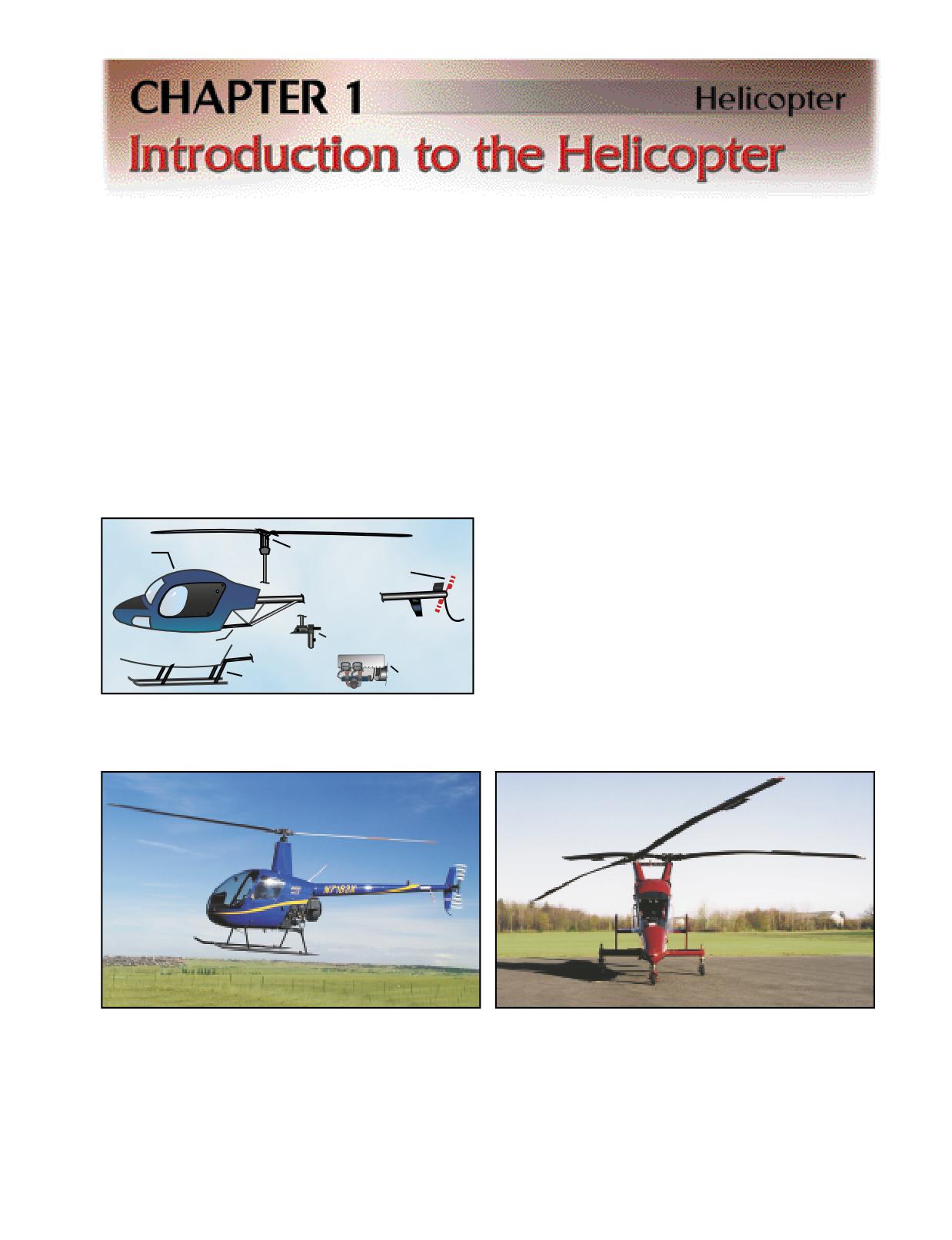
Helicopters come in many sizes and shapes, but most
THE MAIN ROTOR SYSTEM
share the same major components. These components
The rotor system found on helicopters can consist of a
include a cabin where the payload and crew are car-
single main rotor or dual rotors. With most dual rotors,
ried; an airframe, which houses the various compo-
the rotors turn in opposite directions so the torque from
nents, or where components are attached; a powerplant
one rotor is opposed by the torque of the other. This
or engine; and a transmission, which, among other
cancels the turning tendencies. [Figure 1-2]
things, takes the power from the engine and transmits it
to the main rotor, which provides the aerodynamic
In general, a rotor system can be classified as either
forces that make the helicopter fly. Then, to keep the
fully articulated, semirigid, or rigid. There are varia-
helicopter from turning due to torque, there must be
tions and combinations of these systems, which will be
some type of antitorque system. Finally there is the
discussed in greater detail in Chapter 5-Helicopter
landing gear, which could be skids, wheels, skis, or
Systems.
floats. This chapter is an introduction to these compo-
nents. [Figure 1-1]
FULLY ARTICULATED ROTOR SYSTEM
A fully articulated rotor system usually consists of
Main Rotor
Tail Rotor
three or more rotor blades. The blades are allowed to
Cabin
System
System
flap, feather, and lead or lag independently of each
other. Each rotor blade is attached to the rotor hub by a
horizontal hinge, called the flapping hinge, which per-
mits the blades to flap up and down. Each blade can
Airframe
Transmission
move up and down independently of the others. The
Powerplant
flapping hinge may be located at varying distances
Landing Gear
from the rotor hub, and there may be more than one.
Figure 1-1. The major components of a helicopter are the
The position is chosen by each manufacturer, primarily
cabin, airframe, landing gear, powerplant, transmission, main
with regard to stability and control.
rotor system, and tail rotor system.
Figure 1-2. Helicopters can have a single main rotor or a dual rotor system.
Payload-The term used for pas-
Blade Flap-The upward or
Blade Lead or Lag-The fore and
sengers, baggage, and cargo.
downward movement of the rotor
aft movement of the blade in the
blades during rotation.
plane of rotation. It is sometimes
Torque-In helicopters with a sin-
called hunting or dragging.
gle, main rotor system, the ten-
Blade Feather or Feathering-The
dency of the helicopter to turn in
rotation of the blade around the
the opposite direction of the main
spanwise (pitch change) axis.
rotor rotation.
1-1
Each rotor blade is also attached to the hub by a verti-
thrust of the antitorque system to maintain directional
cal hinge, called a drag or lag hinge, that permits each
control whenever the main rotor torque changes, or to
blade, independently of the others, to move back and
make heading changes while hovering.
forth in the plane of the rotor disc. Dampers are nor-
mally incorporated in the design of this type of rotor
FENESTRON
system to prevent excessive motion about the drag
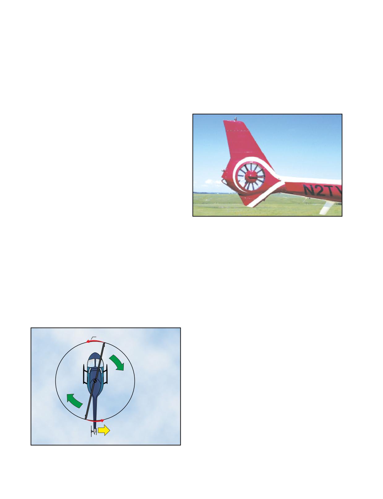
Another form of antitorque rotor is the fenestron or
hinge. The purpose of the drag hinge and dampers is to
“fan-in-tail” design. This system uses a series of rotat-
absorb the acceleration and deceleration of the rotor
ing blades shrouded within a vertical tail. Because the
blades.
blades are located within a circular duct, they are less
likely to come into contact with people or objects.
The blades of a fully articulated rotor can also be feath-
[Figure 1-4]
ered, or rotated about their spanwise axis. To put it
more simply, feathering means the changing of the
pitch angle of the rotor blades.
SEMIRIGID ROTOR SYSTEM
A semirigid rotor system allows for two different
movements, flapping and feathering. This system is
normally comprised of two blades, which are rigidly
attached to the rotor hub. The hub is then attached to
the rotor mast by a trunnion bearing or teetering hinge.
This allows the blades to see-saw or flap together. As
one blade flaps down, the other flaps up. Feathering is
accomplished by the feathering hinge, which changes
the pitch angle of the blade.
Figure 1-4. Compared to an unprotected tail rotor, the fene-
RIGID ROTOR SYSTEM
stron antitorque system provides an improved margin of
The rigid rotor system is mechanically simple, but
safety during ground operations.
structurally complex because operating loads must be
absorbed in bending rather than through hinges. In this
NOTAR®
system, the blades cannot flap or lead and lag, but they
can be feathered.
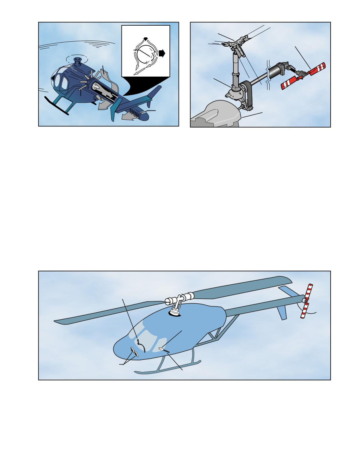
The NOTAR® system is an alternative to the antitorque
rotor. The system uses low-pressure air that is forced
ANTITORQUE SYSTEMS
into the tailboom by a fan mounted within the helicop-
TAIL ROTOR
ter. The air is then fed through horizontal slots, located
Most helicopters with a single, main rotor system
on the right side of the tailboom, and to a controllable
require a separate rotor to overcome torque. This is
rotating nozzle to provide antitorque and directional
accomplished through a variable pitch, antitorque rotor
control. The low-pressure air coming from the horizon-
or tail rotor. [Figure 1-3]. You will need to vary the
tal slots, in conjunction with the downwash from the
main rotor, creates a phenomenon called “Coanda
Blade Rotation
Effect,” which produces a lifting force on the right side
of the tailboom. [Figure 1-5]
LANDING GEAR
The most common landing gear is a skid type gear,
Torque
which is suitable for landing on various types of sur-
faces. Some types of skid gear are equipped with
Torque
dampers so touchdown shocks or jolts are not transmit-
ted to the main rotor system. Other types absorb the
shocks by the bending of the skid attachment arms.
Landing skids may be fitted with replaceable heavy-
duty skid shoes to protect them from excessive wear
Tail Rotor Thrust
and tear.
to Compensate for Torque
Helicopters can also be equipped with floats for water
Figure 1-3. The antitorque rotor produces thrust to oppose
operations, or skis for landing on snow or soft terrain.
torque and helps prevent the helicopter from turning in the
Wheels are another type of landing gear. They may be
opposite direction of the main rotor.
in a tricycle or four point configuration. Normally, the
1-2
Main
Downwash
Rotor
Antitorque
Air
Rotor
Jet
Main Rotor
Wake
Lift
Main
Transmission
Air Intake
Rotating
Nozzle
Engine
Figure 1-5. While in a hover, Coanda Effect supplies approxi-
Figure 1-6. Typically, the engine drives the main rotor through
mately two-thirds of the lift necessary to maintain directional
a transmission and belt drive or centrifugal clutch system.
control. The rest is created by directing the thrust from the
The antitorque rotor is driven from the transmission.
controllable rotating nozzle.
large horsepower output. The engine drives the main
transmission, which then transfers power directly to the
nose or tail gear is free to swivel as the helicopter is
main rotor system, as well as the tail rotor.
taxied on the ground.
POWERPLANT
FLIGHT CONTROLS
A typical small helicopter has a reciprocating engine,
When you begin flying a helicopter, you will use four
which is mounted on the airframe. The engine can be
basic flight controls. They are the cyclic pitch control;
mounted horizontally or vertically with the transmis-
the collective pitch control; the throttle, which is
sion supplying the power to the vertical main rotor
usually a twist grip control located on the end of the
shaft. [Figure 1-6]
collective lever; and the antitorque pedals. The col-
lective and cyclic controls the pitch of the main rotor
Another engine type is the gas turbine. This engine is
blades. The function of these controls will be explained
used in most medium to heavy lift helicopters due to its
in detail in Chapter 4-Flight Controls. [Figure 1-7]
Cyclic
Throttle
Antitorque
Pedals
Collective
Figure 1-7. Location of flight controls.
1-3
1-4
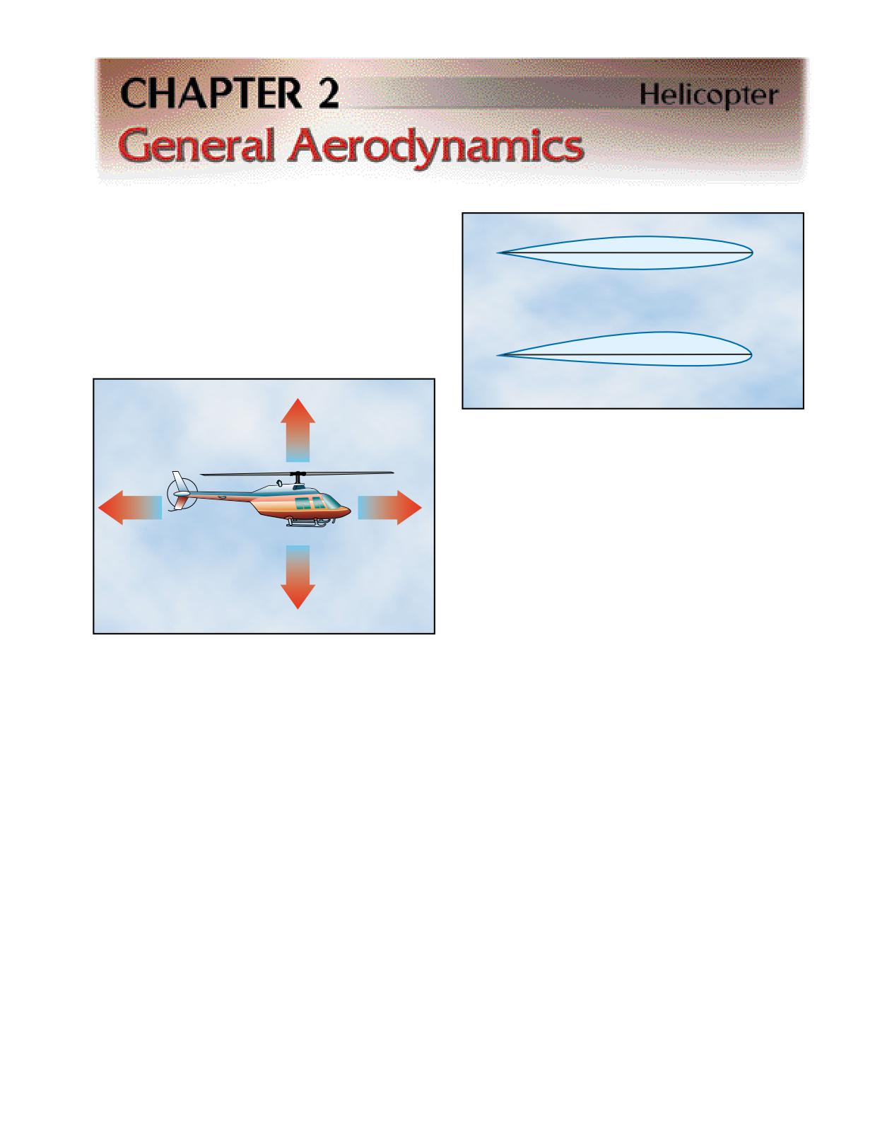
There are four forces acting on a helicopter in flight.
They are lift, weight, thrust, and drag. [Figure 2-1] Lift
is the upward force created by the effect of airflow as it
passes around an airfoil. Weight opposes lift and is
Symmetrical
caused by the downward pull of gravity. Thrust is the
force that propels the helicopter through the air.
Opposing lift and thrust is drag, which is the retarding
force created by development of lift and the movement
of an object through the air.
Asymmetrical
Lift
Figure 2-2. The upper and lower curvatures are the same on a
symmetrical airfoil and vary on an asymmetrical airfoil.
Thrust
Symmetrical blades are very stable, which helps keep
blade twisting and flight control loads to a minimum.
Drag
[Figure 2-2] This stability is achieved by keeping the
center of pressure virtually unchanged as the angle of
attack changes. Center of pressure is the imaginary
point on the chord line where the resultant of all aero-
dynamic forces are considered to be concentrated.
Weight
Today, designers use thinner airfoils and obtain the
Figure 2-1. Four forces acting on a helicopter in forward flight.
required rigidity by using composite materials. In addi-
tion, airfoils are asymmetrical in design, meaning the
upper and lower surface do not have the same camber.
AIRFOIL
Normally these airfoils would not be as stable, but this
can be corrected by bending the trailing edge to produce
Before beginning the discussion of lift, you need to be
the same characteristics as symmetrical airfoils. This is
aware of certain aerodynamic terms that describe an
called “reflexing.” Using this type of rotor blade allows
airfoil and the interaction of the airflow around it.
the rotor system to operate at higher forward speeds.
An airfoil is any surface, such as an airplane wing or a
helicopter rotor blade, which provides aerodynamic
One of the reasons an asymmetrical rotor blade is not
force when it interacts with a moving stream of air.
as stable is that the center of pressure changes with
Although there are many different rotor blade airfoil
changes in angle of attack. When the center of pressure
designs, in most helicopter flight conditions, all airfoils
lifting force is behind the pivot point on a rotor blade, it
perform in the same manner.
tends to cause the rotor disc to pitch up. As the angle of
attack increases, the center of pressure moves forward.
Engineers of the first helicopters designed relatively
If it moves ahead of the pivot point, the pitch of the
thick airfoils for their structural characteristics.
rotor disc decreases. Since the angle of attack of the
Because the rotor blades were very long and slender, it
rotor blades is constantly changing during each cycle
was necessary to incorporate more structural rigidity
of rotation, the blades tend to flap, feather, lead, and
into them. This prevented excessive blade droop when
lag to a greater degree.
the rotor system was idle, and minimized blade twist-
ing while in flight. The airfoils were also designed to
When referring to an airfoil, the span is the distance
be symmetrical, which means they had the same cam-
from the rotor hub to the blade tip. Blade twist refers to
ber (curvature) on both the upper and lower surfaces.
a changing chord line from the blade root to the tip.
2-1
BLADE PITCH ANGLE
Leading
Edge
The pitch angle of a rotor blade is the angle between its
Upper
chord line and the reference plane containing the rotor
Camber
hub. [Figure 2-4] You control the pitch angle of the blades
with the flight controls. The collective pitch changes each
rotor blade an equal amount of pitch no matter where it is
Angle of
Attack
located in the plane of rotation (rotor disc) and is used to
change rotor thrust. The cyclic pitch control changes the
pitch of each blade as a function of where it is in the plane
Lower
of rotation. This allows for trimming the helicopter in
Camber
Trailing
pitch and roll during forward flight and for maneuvering
Edge
in all flight conditions.
Figure 2-3. Aerodynamic terms of an airfoil.
Axis of Rotation
Twisting a rotor blade causes it to produce a more even
amount of lift along its span. This is necessary because
Pitch
rotational velocity increases toward the blade tip. The
Angle
Reference Plane
leading edge is the first part of the airfoil to meet the
oncoming air. [Figure 2-3] The trailing edge is the aft
portion where the airflow over the upper surface joins
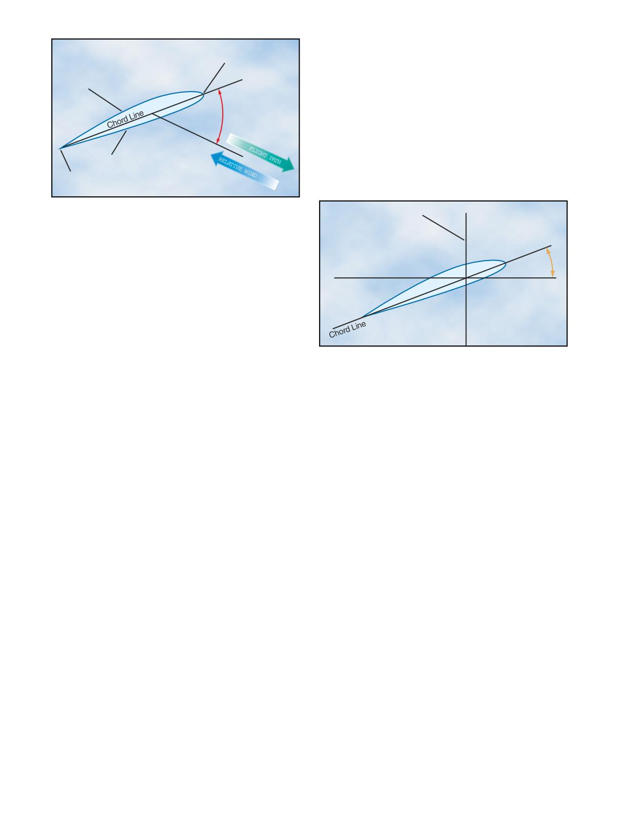
the airflow under the lower surface. The chord line is
an imaginary straight line drawn from the leading to
the trailing edge. The camber is the curvature of the air-
Figure 2-4. Do not confuse the axis of rotation with the rotor
foil’s upper and lower surfaces. The relative wind is the
mast. The only time they coincide is when the tip-path plane
wind moving past the airfoil. The direction of this wind
is perpendicular to the rotor mast.
is relative to the attitude, or position, of the airfoil and
is always parallel, equal, and opposite in direction to
the flight path of the airfoil. The angle of attack is the
ANGLE OF ATTACK
angle between the blade chord line and the direction of
When the angle of attack is increased, air flowing over
the relative wind.
the airfoil is diverted over a greater distance, resulting
in an increase of air velocity and more lift. As angle of
RELATIVE WIND
attack is increased further, it becomes more difficult for
Relative wind is created by the motion of an airfoil
air to flow smoothly across the top of the airfoil. At this
through the air, by the motion of air past an airfoil, or by
point the airflow begins to separate from the airfoil and
a combination of the two. Relative wind may be
enters a burbling or turbulent pattern. The turbulence
affected by several factors, including the rotation of the
results in a large increase in drag and loss of lift in the
rotor blades, horizontal movement of the helicopter,
area where it is taking place. Increasing the angle of
flapping of the rotor blades, and wind speed and direction.
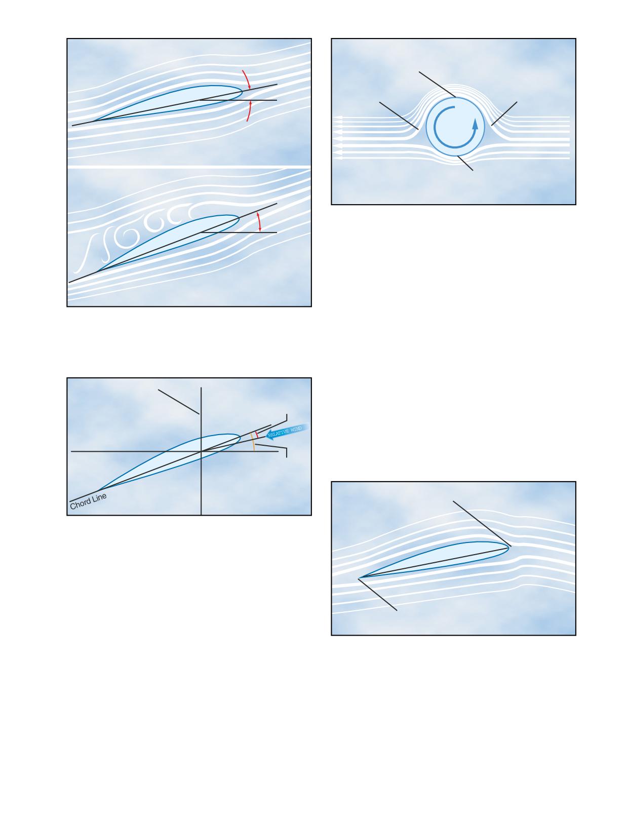
attack increases lift until the critical angle of attack is
reached. Any increase in the angle of attack beyond this
For a helicopter, the relative wind is the flow of air with
point produces a stall and a rapid decrease in lift.
respect to the rotor blades. If the rotor is stopped, wind
[Figure 2-5]
blowing over the blades creates a relative wind. When
the helicopter is hovering in a no-wind condition, rela-
tive wind is created by the motion of the rotor blades
Angle of attack should not be confused with pitch
through the air. If the helicopter is hovering in a wind,
angle. Pitch angle is determined by the direction of the
the relative wind is a combination of the wind and the
relative wind. You can, however, change the angle of
motion of the rotor blades through the air. When the
attack by changing the pitch angle through the use of
helicopter is in forward flight, the relative wind is a
the flight controls. If the pitch angle is increased, the
combination of the rotation of the rotor blades and the
angle of attack is increased, if the pitch angle is
forward speed of the helicopter.
reduced, the angle of attack is reduced. [Figure 2-6]
Axis-of-Rotation-The imaginary
Tip-Path Plane-The imaginary
Aircraft Pitch-When referenced
Aircraft Roll-Is the movement of
line about which the rotor rotates.
circular plane outlined by the
to a helicopter, is the movement of
the helicopter about its longitudi-
It is represented by a line drawn
rotor blade tips as they make a
the helicopter about its lateral, or
nal, or nose to tail axis. Movement
through the center of, and perpen-
cycle of rotation.
side to side axis. Movement of the
of the cyclic right or left causes the
dicular to, the tip-path plane.
cyclic forward or aft causes the
helicopter to tilt in that direction.
nose of the helicopter to move up
or down.
2-2
Increased Local Velocity
(Decreased pressure)
8°
Downwash
Upwash
B
A
LIFT
Decreased Local Velocity
Figure 2-7. Magnus Effect is a lifting force produced when a
12-16°
rotating cylinder produces a pressure differential. This is the
same effect that makes a baseball curve or a golf ball slice.
now have upwash ahead of the rotating cylinder and
STALL
downwash at the rear.
Figure 2-5. As the angle of attack is increased, the separation
The difference in surface velocity accounts for a differ-
point starts near the trailing edge of the airfoil and pro-
ence in pressure, with the pressure being lower on the
gresses forward. Finally, the airfoil loses its lift and a stall
top than the bottom. This low pressure area produces
condition occurs.
an upward force known as the “Magnus Effect.” This
mechanically induced circulation illustrates the rela-
tionship between circulation and lift.
Axis of Rotation
ngle of
A
Attack
An airfoil with a positive angle of attack develops air
circulation as its sharp trailing edge forces the rear
stagnation point to be aft of the trailing edge, while the
Reference Plane
front stagnation point is below the leading edge.
[Figure 2-8]
Pitch
Angle
Leading Edge
Stagnation Point
Figure 2-6. Angle of attack may be greater than, less than, or
the same as the pitch angle.
A
LIFT
B
MAGNUS EFFECT
The explanation of lift can best be explained by looking
at a cylinder rotating in an airstream. The local velocity
Trailing Edge
near the cylinder is composed of the airstream velocity
Stagnation Point
and the cylinder’s rotational velocity, which decreases
with distance from the cylinder. On a cylinder, which is
Figure 2-8. Air circulation around an airfoil occurs when the
front stagnation point is below the leading edge and the aft
rotating in such a way that the top surface area is rotating
stagnation point is beyond the trailing edge.
in the same direction as the airflow, the local velocity at
the surface is high on top and low on the bottom.
As shown in figure 2-7, at point “A,” a stagnation point
BERNOULLI’S PRINCIPLE
exists where the airstream line that impinges on the sur-
Air flowing over the top surface accelerates. The airfoil
face splits; some air goes over and some under. Another
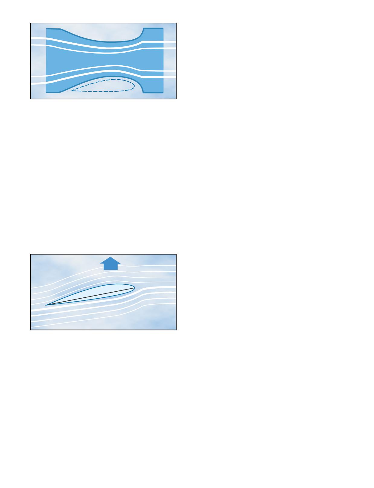
is now subjected to Bernoulli’s Principle or the “venturi
stagnation point exists at “B,” where the two air
effect.” As air velocity increases through the constricted
streams rejoin and resume at identical velocities. We
portion of a venturi tube, the pressure decreases.
2-3
ward. According to Newton’s Third Law of Motion,
“for every action there is an equal and opposite reac-
tion,” the air that is deflected downward also produces
an upward (lifting) reaction.
Increased Velocity
Decreased Pressure
Since air is much like water, the explanation for this
source of lift may be compared to the planing effect of
skis on water. The lift which supports the water skis
(and the skier) is the force caused by the impact pres-
sure and the deflection of water from the lower surfaces
of the skis.
Figure 2-9. The upper surface of an airfoil is similar to the
constriction in a venturi tube.
Under most flying conditions, the impact pressure and
the deflection of air from the lower surface of the rotor
blade provides a comparatively small percentage of the
Compare the upper surface of an airfoil with the con-
total lift. The majority of lift is the result of decreased
striction in a venturi tube that is narrower in the middle
pressure above the blade, rather than the increased
than at the ends. [Figure 2-9]
pressure below it.
The upper half of the venturi tube can be replaced by
layers of undisturbed air. Thus, as air flows over the
WEIGHT
upper surface of an airfoil, the camber of the airfoil
Normally, weight is thought of as being a known, fixed
causes an increase in the speed of the airflow. The
value, such as the weight of the helicopter, fuel, and
increased speed of airflow results in a decrease in pres-
occupants. To lift the helicopter off the ground verti-
sure on the upper surface of the airfoil. At the same
cally, the rotor system must generate enough lift to
time, air flows along the lower surface of the airfoil,
overcome or offset the total weight of the helicopter
building up pressure. The combination of decreased
and its occupants. This is accomplished by increasing
pressure on the upper surface and increased pressure
the pitch angle of the main rotor blades.
on the lower surface results in an upward force.
[Figure 2-10]
The weight of the helicopter can also be influenced by
aerodynamic loads. When you bank a helicopter while
maintaining a constant altitude, the “G” load or load
Lift
Decreased Pressure
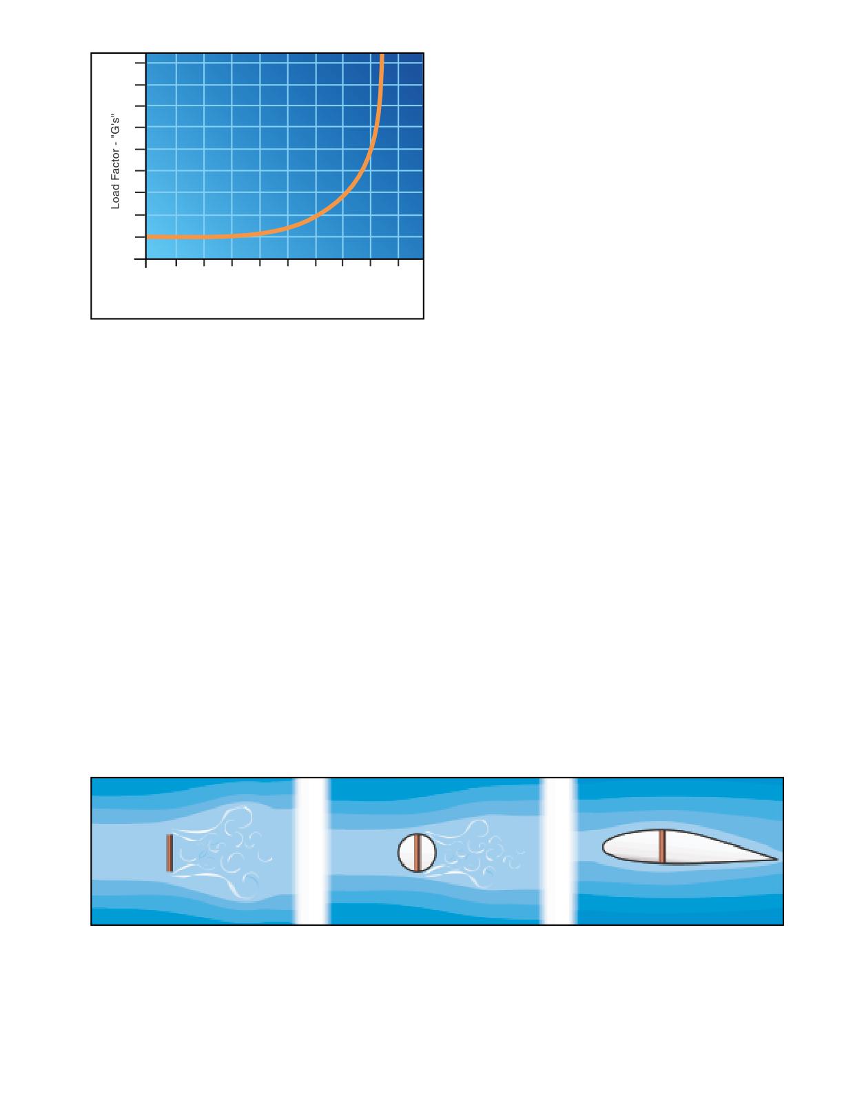
factor increases. Load factor is the ratio of the load sup-
ported by the main rotor system to the actual weight of
the helicopter and its contents. In steady-state flight,
the helicopter has a load factor of one, which means the
main rotor system is supporting the actual total weight
of the helicopter. If you increase the bank angle to 60°,
Increased Pressure
while still maintaining a constant altitude, the load fac-
tor increases to two. In this case, the main rotor system
has to support twice the weight of the helicopter and its
contents. [Figure 2-11]
Figure 2-10. Lift is produced when there is decreased pres-
sure above and increased pressure below an airfoil.
Disc loading of a helicopter is the ratio of weight to the
total main rotor disc area, and is determined by divid-
As angle of attack is increased, the production of lift is
ing the total helicopter weight by the rotor disc area,
increased. More upwash is created ahead of the airfoil
which is the area swept by the blades of a rotor. Disc
as the leading edge stagnation point moves under the
area can be found by using the span of one rotor blade
leading edge, and more downwash is created aft of the
as the radius of a circle and then determining the area
trailing edge. Total lift now being produced is perpen-
the blades encompass during a complete rotation. As
dicular to relative wind. In summary, the production of
the helicopter is maneuvered, disc loading changes.
lift is based upon the airfoil creating circulation in the
The higher the loading, the more power you need to
airstream (Magnus Effect) and creating differential
maintain rotor speed.
pressure on the airfoil (Bernoulli’s Principle).
Steady-State Flight-A condition
NEWTON’S THIRD LAW OF MOTION
when an aircraft is in straight-
Additional lift is provided by the rotor blade’s lower
and-level, unaccelerated flight,
surface as air striking the underside is deflected down-
and all forces are in balance.
2-4
9
DRAG
8
The force that resists the movement of a helicopter
through the air and is produced when lift is developed
7
is called drag. Drag always acts parallel to the relative
6
wind. Total drag is composed of three types of drag:
5
profile, induced, and parasite.
4
3
PROFILE DRAG
Profile drag develops from the frictional resistance of
2
the blades passing through the air. It does not change
1
significantly with the airfoil’s angle of attack, but
0
increases moderately when airspeed increases. Profile
0
10
20
30
40
50
60
70
80
90
drag is composed of form drag and skin friction.
Bank Angle (in Degrees)
Form drag results from the turbulent wake caused by
the separation of airflow from the surface of a struc-
Figure 2-11. The load factor diagram allows you to calculate
the amount of “G” loading exerted with various angle of
ture. The amount of drag is related to both the size and
bank.
shape of the structure that protrudes into the relative
wind. [Figure 2-12]
THRUST
Skin friction is caused by surface roughness. Even
Thrust, like lift, is generated by the rotation of the
though the surface appears smooth, it may be quite
main rotor system. In a helicopter, thrust can be for-
rough when viewed under a microscope. A thin layer of
ward, rearward, sideward, or vertical. The resultant of
air clings to the rough surface and creates small eddies
lift and thrust determines the direction of movement of
that contribute to drag.
the helicopter.
INDUCED DRAG
Induced drag is generated by the airflow circulation
The solidity ratio is the ratio of the total rotor blade
around the rotor blade as it creates lift. The high-pres-
area, which is the combined area of all the main rotor
sure area beneath the blade joins the low-pressure air
blades, to the total rotor disc area. This ratio provides a
above the blade at the trailing edge and at the rotor tips.
means to measure the potential for a rotor system to
This causes a spiral, or vortex, which trails behind each
provide thrust.
blade whenever lift is being produced. These vortices
deflect the airstream downward in the vicinity of the
blade, creating an increase in downwash. Therefore,
The tail rotor also produces thrust. The amount of
the blade operates in an average relative wind that is
thrust is variable through the use of the antitorque ped-
inclined downward and rearward near the blade.
als and is used to control the helicopter’s yaw.
Because the lift produced by the blade is perpendicular
Figure 2-12. It is easy to visualize the creation of form drag by examining the airflow around a flat plate. Streamlining decreases
form drag by reducing the airflow separation.
Aircraft Yaw-The movement of
the helicopter about its vertical
axis.
2-5
to the relative wind, the lift is inclined aft by the same
with increasing airspeed, parasite drag is the major cause
amount. The component of lift that is acting in a rear-
of drag at higher airspeeds. Parasite drag varies with the
ward direction is induced drag. [Figure 2-13]
square of the velocity. Doubling the airspeed increases
the parasite drag four times.
Induced Drag
TOTAL DRAG
Total drag for a helicopter is the sum of all three drag
forces. [Figure 2-14] As airspeed increases, parasite
drag increases, while induced drag decreases. Profile
drag remains relatively constant throughout the speed
range with some increase at higher airspeeds.
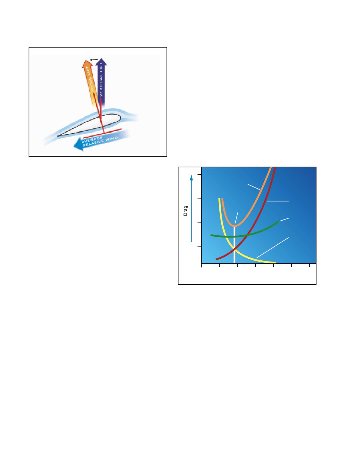
Combining all drag forces results in a total drag curve.
The low point on the total drag curve shows the air-
speed at which drag is minimized. This is the point
where the lift-to-drag ratio is greatest and is referred to
as L/Dmax. At this speed, the total lift capacity of the
helicopter, when compared to the total drag of the heli-
copter, is most favorable. This is important in helicopter
performance.
Figure 2-13. The formation of induced drag is associated with
the downward deflection of the airstream near the rotor
blade.
Total Drag
As the air pressure differential increases with an
Minimum
increase in angle of attack, stronger vortices form, and
Parasite
Drag or
induced drag increases. Since the blade’s angle of
L/Dmax
Drag
attack is usually lower at higher airspeeds, and higher
Profile
at low speeds, induced drag decreases as airspeed
Drag
increases and increases as airspeed decreases. Induced
drag is the major cause of drag at lower airspeeds.
Induced
Drag
PARASITE DRAG
Parasite drag is present any time the helicopter is moving
through the air. This type of drag increases with airspeed.
0
25
50
75
100
125
150
Nonlifting components of the helicopter, such as the
Speed
cabin, rotor mast, tail, and landing gear, contribute to par-
asite drag. Any loss of momentum by the airstream, due
Figure 2-14. The total drag curve represents the combined
to such things as openings for engine cooling, creates
forces of parasite, profile, and induced drag; and is plotted
additional parasite drag. Because of its rapid increase
against airspeed.
L/Dmax-The maximum ratio
between total lift (L) and the total
drag (D). This point provides the
best glide speed. Any deviation
from best glide speed increases
drag and reduces the distance you
can glide.
2-6
Once a helicopter leaves the ground, it is acted upon by
The weight that must be supported is the total weight of the
the four aerodynamic forces. In this chapter, we will
helicopter and its occupants. If the amount of thrust is
examine these forces as they relate to flight maneuvers.
greater than the actual weight, the helicopter gains altitude;
if thrust is less than weight, the helicopter loses altitude.
POWERED FLIGHT
The drag of a hovering helicopter is mainly induced drag
In powered flight (hovering, vertical, forward, side-
incurred while the blades are producing lift. There is,
ward, or rearward), the total lift and thrust forces of a
however, some profile drag on the blades as they rotate
rotor are perpendicular to the tip-path plane or plane of
through the air. Throughout the rest of this discussion,
rotation of the rotor.
the term “drag” includes both induced and profile drag.
HOVERING FLIGHT
An important consequence of producing thrust is
For standardization purposes, this discussion assumes
torque. As stated before, for every action there is an
a stationary hover in a no-wind condition. During hov-
equal and opposite reaction. Therefore, as the engine
ering flight, a helicopter maintains a constant position
turns the main rotor system in a counterclockwise
over a selected point, usually a few feet above the
direction, the helicopter fuselage turns clockwise. The
ground. For a helicopter to hover, the lift and thrust
amount of torque is directly related to the amount of
produced by the rotor system act straight up and must
engine power being used to turn the main rotor system.
equal the weight and drag, which act straight down.
Remember, as power changes, torque changes.
While hovering, you can change the amount of main
To counteract this torque-induced turning tendency, an
rotor thrust to maintain the desired hovering altitude.
antitorque rotor or tail rotor is incorporated into most
This is done by changing the angle of attack of the main
helicopter designs. You can vary the amount of thrust
rotor blades and by varying power, as needed. In this
produced by the tail rotor in relation to the amount of
case, thrust acts in the same vertical direction as lift.
torque produced by the engine. As the engine supplies
[Figure 3-1]
more power, the tail rotor must produce more thrust.
This is done through the use of antitorque pedals.
TRANSLATING TENDENCY OR DRIFT
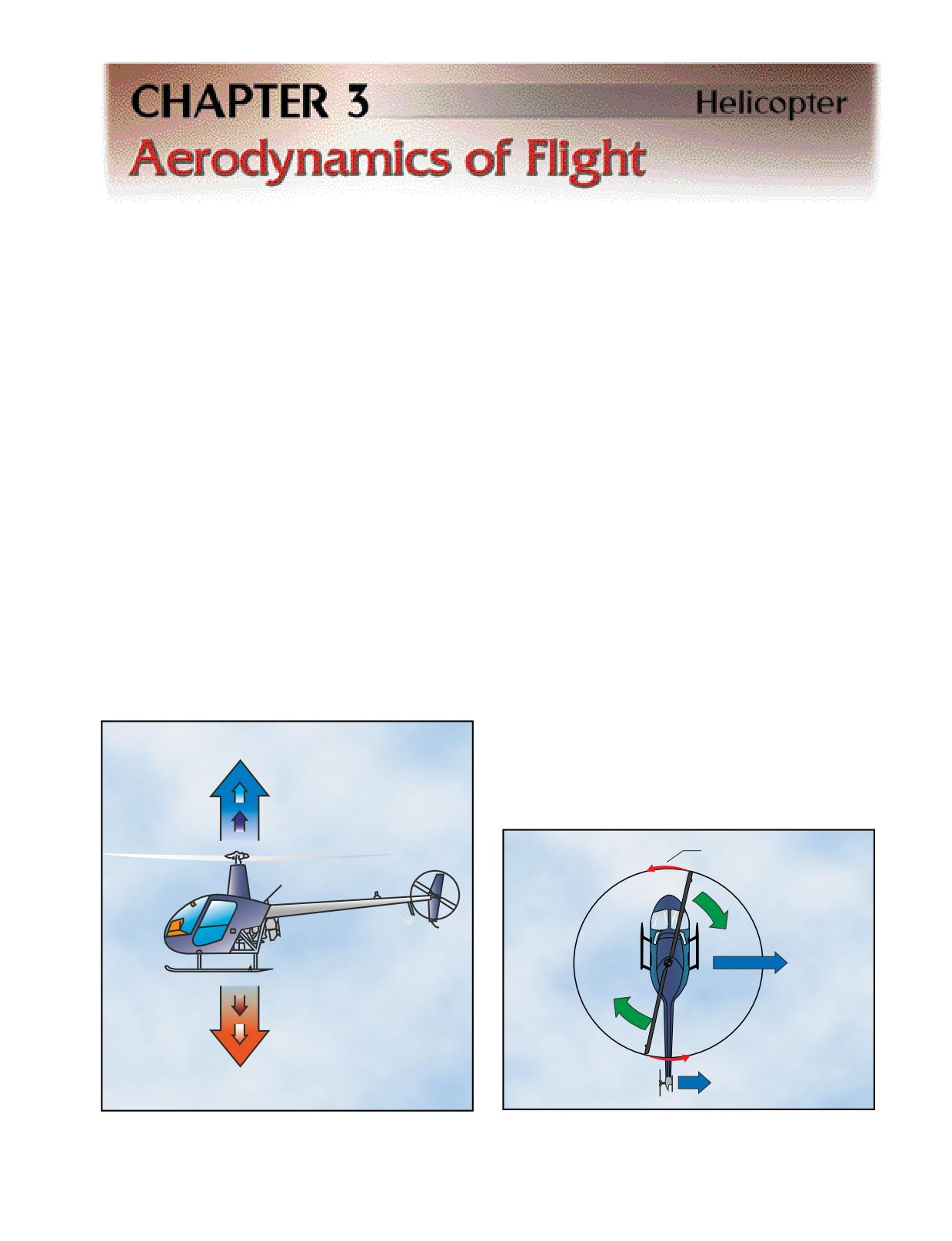
During hovering flight, a single main rotor helicopter tends
to drift in the same direction as antitorque rotor thrust. This
Thrust
drifting tendency is called translating tendency. [Figure 3-2]
Lift
Blade Rotation
Torque
Drift
Torque
Weight
Drag
Tail Rotor Thrust
Figure 3-1. To maintain a hover at a constant altitude, enough
Figure 3-2. A tail rotor is designed to produce thrust in a
lift and thrust must be generated to equal the weight of the
direction opposite torque. The thrust produced by the tail
helicopter and the drag produced by the rotor blades.
rotor is sufficient to move the helicopter laterally.
3-1
To counteract this drift, one or more of the following
greater the centrifugal force. This force gives the rotor
features may be used:
blades their rigidity and, in turn, the strength to support
the weight of the helicopter. The centrifugal force gen-
•
The main transmission is mounted so that the rotor
erated determines the maximum operating rotor r.p.m.
mast is rigged for the tip-path plane to have a built-
due to structural limitations on the main rotor system.
in tilt opposite tail thrust, thus producing a small
sideward thrust.
As a vertical takeoff is made, two major forces are act-
ing at the same time-centrifugal force acting outward
•
Flight control rigging is designed so that the rotor
and perpendicular to the rotor mast, and lift acting
disc is tilted slightly opposite tail rotor thrust when
upward and parallel to the mast. The result of these two
the cyclic is centered.
forces is that the blades assume a conical path instead
of remaining in the plane perpendicular to the mast.
•
The cyclic pitch control system is designed so that
[Figure 3-4]
the rotor disc tilts slightly opposite tail rotor thrust
when in a hover.
Counteracting translating tendency, in a helicopter with a
counterclockwise main rotor system, causes the left skid
Resultant
Before Takeoff
Blade
to hang lower while hovering. The opposite is true for
Lift
Angle
rotor systems turning clockwise when viewed from above.
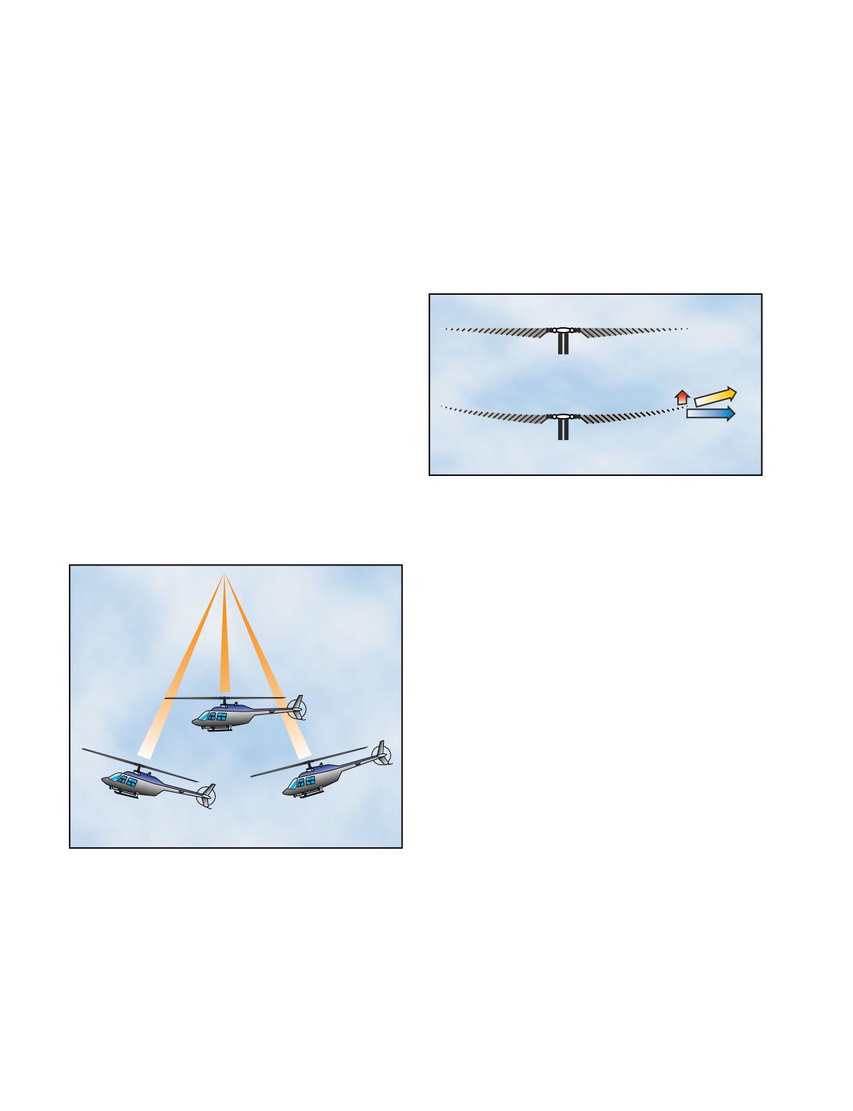
PENDULAR ACTION
Centrifugal
Since the fuselage of the helicopter, with a single main
Force
During Takeoff
rotor, is suspended from a single point and has consider-
able mass, it is free to oscillate either longitudinally or
laterally in the same way as a pendulum. This pendular
Figure 3-4. Rotor blade coning occurs as the rotor blades
action can be exaggerated by over controlling; therefore,
begin to lift the weight of the helicopter. In a semirigid and
rigid rotor system, coning results in blade bending. In an
control movements should be smooth and not exagger-
articulated rotor system, the blades assume an upward angle
ated. [Figure 3-3]
through movement about the flapping hinges.
CORIOLIS EFFECT
(LAW OF CONSERVATION
OF ANGULAR MOMENTUM)
Coriolis Effect, which is sometimes referred to as con-
servation of angular momentum, might be compared to
spinning skaters. When they extend their arms, their
rotation slows down because the center of mass moves
farther from the axis of rotation. When their arms are
retracted, the rotation speeds up because the center of
Hover
mass moves closer to the axis of rotation.
When a rotor blade flaps upward, the center of mass of
that blade moves closer to the axis of rotation and blade
Rearward
Forward
acceleration takes place in order to conserve angular
Flight
Flight
momentum. Conversely, when that blade flaps down-
ward, its center of mass moves further from the axis of
Figure 3-3. Because the helicopter’s body has mass and is
suspended from a single point (the rotor mast head), it tends
to act much like a pendulum.
CONING
In order for a helicopter to generate lift, the rotor blades
must be turning. This creates a relative wind that is
Centrifugal Force-The apparent
opposite the direction of rotor system rotation. The
force that an object moving along
a circular path exerts on the body
rotation of the rotor system creates centrifugal force
constraining the obect and that
(inertia), which tends to pull the blades straight outward
acts outwardy away from the cen-
from the main rotor hub. The faster the rotation, the
ter of rotation.
3-2
rotation and blade deceleration takes place. [Figure 3-5]
subject to Coriolis Effect comparable to that of a fully
Keep in mind that due to coning, a rotor blade will not
articulated system.
flap below a plane passing through the rotor hub and
perpendicular to the axis of rotation. The acceleration
and deceleration actions of the rotor blades are absorbed
CM
CM
by either dampers or the blade structure itself, depend-
ing upon the design of the rotor system.
Mast
Axis
Axis of
Blade
CM
Flapping
Rotation
CM
This elbow moves away from
This elbow moves toward
the mast as the rotor is tilted.
the mast as the rotor is tilted.
Figure 3-6. Because of the underslung rotor, the center of
mass remains approximately the same distance from the
Center of Mass
mast after the rotor is tilted.
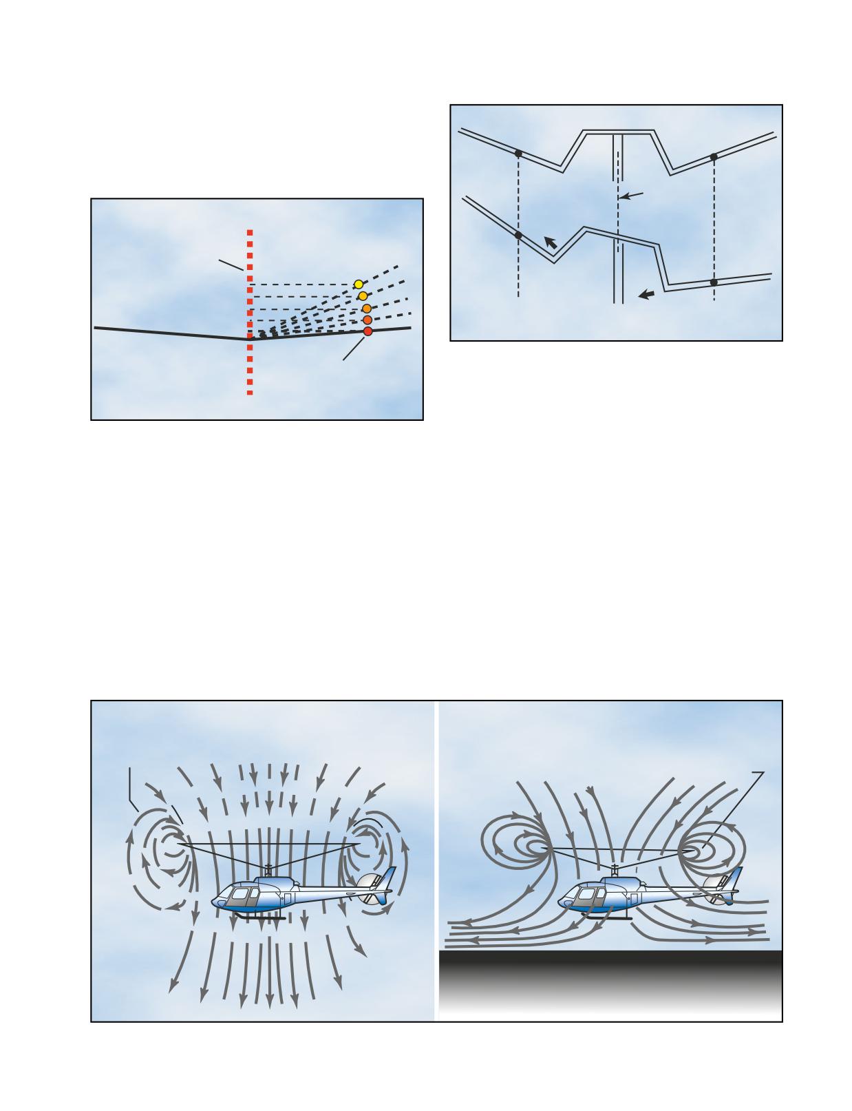
GROUND EFFECT
Figure 3-5. The tendency of a rotor blade to increase or
decrease its velocity in its plane of rotation due to mass
When hovering near the ground, a phenomenon known
movement is known as Coriolis Effect, named for the mathe-
as ground effect takes place. [Figure 3-7] This effect
matician who made studies of forces generated by radial
usually occurs less than one rotor diameter above the
movements of mass on a rotating disc.
surface. As the induced airflow through the rotor disc is
reduced by the surface friction, the lift vector increases.
This allows a lower rotor blade angle for the same
Two-bladed rotor systems are normally subject to
amount of lift, which reduces induced drag. Ground
Coriolis Effect to a much lesser degree than are articu-
effect also restricts the generation of blade tip vortices
lated rotor systems since the blades are generally
due to the downward and outward airflow making a
“underslung” with respect to the rotor hub, and the
larger portion of the blade produce lift. When the heli-
change in the distance of the center of mass from the
copter gains altitude vertically, with no forward air-
axis of rotation is small. [Figure 3-6] The hunting
speed, induced airflow is no longer restricted, and the
action is absorbed by the blades through bending. If a
blade tip vortices increase with the decrease in outward
two-bladed rotor system is not “underslung,” it will be
airflow. As a result, drag increases which means a
OUT OF GROUND EFFECT (OGE)
IN GROUND EFFECT (IGE)
Large Blade
Tip Vortex
Blade Tip
No Wind Hover
Vortex
Downwash Pattern
Equidistant 360°
Figure 3-7. Air circulation patterns change when hovering out of ground effect (OGE) and when hovering in ground effect (IGE).
3-3
Axis
New Axis
Old Axis
Gyro Tips
Down Here
90°
Upward
Reaction
Gyro Tips
Force
Occurs
Up Here
Applied
Here
Here
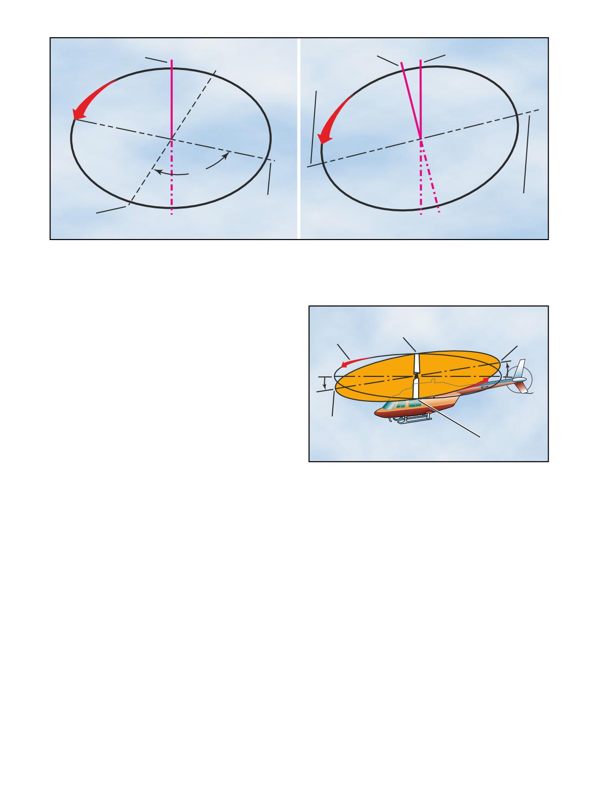
Figure 3-8. Gyroscopic precession principle-when a force is applied to a spinning gyro, the maximum reaction occurs approx-
imately 90° later in the direction of rotation.
higher pitch angle, and more power is needed to move
the air down through the rotor.
Angle of Attack
Maximum
Blade
Decreased
Upward
Rotation
Deflection
Ground effect is at its maximum in a no-wind condition
over a firm, smooth surface. Tall grass, rough terrain,
revetments, and water surfaces alter the airflow pattern,
causing an increase in rotor tip vortices.
GYROSCOPIC PRECESSION
Maximum
The spinning main rotor of a helicopter acts like a gyro-
Downward
scope. As such, it has the properties of gyroscopic
Angle of Attack
Deflection
action, one of which is precession. Gyroscopic preces-
Increased
sion is the resultant action or deflection of a spinning
object when a force is applied to this object. This action
Figure 3-9. With a counterclockwise main rotor blade rota-
tion, as each blade passes the 90° position on the left, the
occurs approximately 90° in the direction of rotation
maximum increase in angle of attack occurs. As each blade
from the point where the force is applied. [Figure 3-8]
passes the 90° position to the right, the maximum decrease
in angle of attack occurs. Maximum deflection takes place
Let us look at a two-bladed rotor system to see how
90° later-maximum upward deflection at the rear and maxi-
gyroscopic precession affects the movement of the tip-
mum downward deflection at the front-and the tip-path
plane tips forward.
path plane. Moving the cyclic pitch control increases
the angle of attack of one rotor blade with the result
that a greater lifting force is applied at that point in the
plane of rotation. This same control movement simul-
taneously decreases the angle of attack of the other
In a rotor system using three or more blades, the move-
blade the same amount, thus decreasing the lifting force
ment of the cyclic pitch control changes the angle of
applied at that point in the plane of rotation. The blade
attack of each blade an appropriate amount so that the
with the increased angle of attack tends to flap up; the
end result is the same.
blade with the decreased angle of attack tends to flap
down. Because the rotor disk acts like a gyro, the
VERTICAL FLIGHT
blades reach maximum deflection at a point approxi-
Hovering is actually an element of vertical flight.
mately 90° later in the plane of rotation. As shown in
Increasing the angle of attack of the rotor blades (pitch)
figure 3-9, the retreating blade angle of attack is
while their velocity remains constant generates addi-
increased and the advancing blade angle of attack is
tional vertical lift and thrust and the helicopter ascends.
decreased resulting in a tipping forward of the tip-path
Decreasing the pitch causes the helicopter to descend.
plane, since maximum deflection takes place 90° later
In a no wind condition when lift and thrust are less than
when the blades are at the rear and front, respectively.
weight and drag, the helicopter descends vertically. If
3-4
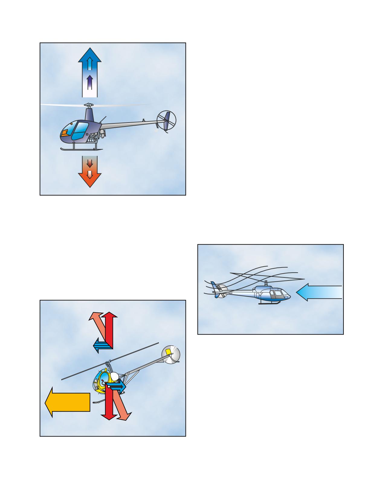
lift and thrust are greater than weight and drag, the hel-
In straight-and-level, unaccelerated forward flight, lift
icopter ascends vertically. [Figure 3-10]
equals weight and thrust equals drag (straight-and-level
flight is flight with a constant heading and at a constant
altitude). If lift exceeds weight, the helicopter climbs;
if lift is less than weight, the helicopter descends. If
thrust exceeds drag, the helicopter speeds up; if thrust
Thrust
is less than drag, it slows down.
Vertical Ascent
Lift
As the helicopter moves forward, it begins to lose alti-
tude because of the lift that is lost as thrust is diverted
forward. However, as the helicopter begins to acceler-
ate, the rotor system becomes more efficient due to the
increased airflow. The result is excess power over that
which is required to hover. Continued acceleration
causes an even larger increase in airflow through the
rotor disc and more excess power.
TRANSLATIONAL LIFT
Weight
Translational lift is present with any horizontal flow of
air across the rotor. This increased flow is most notice-
Drag
able when the airspeed reaches approximately 16 to 24
knots. As the helicopter accelerates through this speed,
the rotor moves out of its vortices and is in relatively
Figure 3-10. To ascend vertically, more lift and thrust must be
undisturbed air. The airflow is also now more horizontal,
generated to overcome the forces of weight and the drag.
which reduces induced flow and drag with a correspon-
ding increase in angle of attack and lift. The additional
lift available at this speed is referred to as “effective
FORWARD FLIGHT
translational lift” (ETL). [Figure 3-12]
In or during forward flight, the tip-path plane is tilted for-
ward, thus tilting the total lift-thrust force forward from
the vertical. This resultant lift-thrust force can be resolved
into two components-lift acting vertically upward and
No Recirculation
of Air
thrust acting horizontally in the direction of flight. In
More Horizontal
addition to lift and thrust, there is weight (the downward
Flow of Air
acting force) and drag (the rearward acting or retarding
force of inertia and wind resistance). [Figure 3-11]
16 to 24
Knots
Tail Rotor Operates in
Resultant
Reduced
Relatively Clean Air
Induced Flow
Increases
Lift
Angle of Attack
Figure 3-12. Effective translational lift is easily recognized in
Thrust
actual flight by a transient induced aerodynamic vibration
and increased performance of the helicopter.
When a single-rotor helicopter flies through translational
Drag
lift, the air flowing through the main rotor and over the
tail rotor becomes less turbulent and more aerodynami-
Helicopter
cally efficient. As the tail rotor efficiency improves,
Movement
more thrust is produced causing the aircraft to yaw left
in a counterclockwise rotor system. It will be necessary
Weight
Resultant
to use right torque pedal to correct for this tendency on
takeoff. Also, if no corrections are made, the nose rises
or pitches up, and rolls to the right. This is caused by
Figure 3-11. To transition into forward flight, some of the ver-
combined effects of dissymmetry of lift and transverse
tical thrust must be vectored horizontally. You initiate this by
forward movement of the cyclic control.
flow effect, and is corrected with cyclic control.
3-5
Translational lift is also present in a stationary hover if
ates through approximately 20 knots or if the headwind
the wind speed is approximately 16 to 24 knots. In nor-
is approximately 20 knots.
mal operations, always utilize the benefit of translational
lift, especially if maximum performance is needed.
You can recognize transverse flow effect because of
increased vibrations of the helicopter at airspeeds just
INDUCED FLOW
below effective translational lift on takeoff and after
As the rotor blades rotate they generate what is called
passing through effective translational lift during land-
rotational relative wind. This airflow is characterized
ing. To counteract transverse flow effect, a cyclic input
as flowing parallel and opposite the rotor’s plane of
needs to be made.
rotation and striking perpendicular to the rotor blade’s
leading edge. This rotational relative wind is used to
DISSYMMETRY OF LIFT
generate lift. As rotor blades produce lift, air is acceler-
When the helicopter moves through the air, the relative
ated over the foil and projected downward. Anytime a
airflow through the main rotor disc is different on the
helicopter is producing lift, it moves large masses of air
advancing side than on the retreating side. The relative
vertically and down through the rotor system. This
wind encountered by the advancing blade is increased
downwash or induced flow can significantly change
by the forward speed of the helicopter, while the rela-
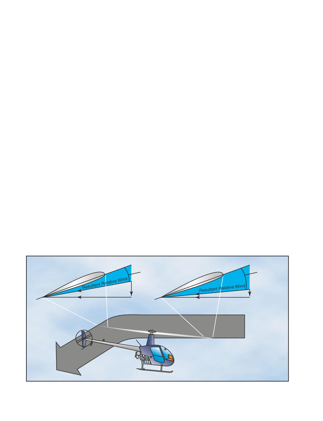
the efficiency of the rotor system. Rotational relative
tive wind speed acting on the retreating blade is
wind combines with induced flow to form the resultant
reduced by the helicopter’s forward airspeed.
relative wind. As induced flow increases, resultant rel-
Therefore, as a result of the relative wind speed, the
ative wind becomes less horizontal. Since angle of
advancing blade side of the rotor disc produces more
attack is determined by measuring the difference
lift than the retreating blade side. This situation is
between the chord line and the resultant relative wind,
defined as dissymmetry of lift. [Figure 3-14]
as the resultant relative wind becomes less horizontal,
angle of attack decreases. [Figure 3-13]
If this condition was allowed to exist, a helicopter with
TRANSVERSE FLOW EFFECT
a counterclockwise main rotor blade rotation would roll
As the helicopter accelerates in forward flight, induced
to the left because of the difference in lift. In reality, the
flow drops to near zero at the forward disc area and
main rotor blades flap and feather automatically to
increases at the aft disc area. This increases the angle
equalize lift across the rotor disc. Articulated rotor sys-
of attack at the front disc area causing the rotor blade to
tems, usually with three or more blades, incorporate a
flap up, and reduces angle of attack at the aft disc area
horizontal hinge (flapping hinge) to allow the individ-
causing the rotor blade to flap down. Because the rotor
ual rotor blades to move, or flap up and down as they
acts like a gyro, maximum displacement occurs 90° in
rotate. A semirigid rotor system (two blades) utilizes a
the direction of rotation. The result is a tendency for
teetering hinge, which allows the blades to flap as a
the helicopter to roll slightly to the right as it acceler-
unit. When one blade flaps up, the other flaps down.
Angle of
Angle of
Attack
A
B
Attack
Induced
Induced
Flow
Flow
Rotational Relative Wind
Rotational Relative Wind
10 to 20
A
Knots
B
Figure 3-13. A helicopter in forward flight, or hovering with a headwind or crosswind, has more molecules of air entering the aft
portion of the rotor blade. Therefore, the angle of attack is less and the induced flow is greater at the rear of the rotor disc.
3-6
which reduces the amount of lift produced by the blade.
Direction
At position (C) the rotor blade is now at its maximum
of Flight
Retreating
Advancing
downflapping velocity. Due to downflapping, the angle
Side
Side
between the chord line and the resultant relative wind
increases. This increases the angle of attack and thus
Blade Tip
Blade Tip
Speed Minus
Speed Plus
the amount of lift produced by the blade.
Helicopter
Helicopter
Speed
Speed
The combination of blade flapping and slow relative wind
(200 KTS)
(400 KTS)
acting on the retreating blade normally limits the maxi-
Blade
mum forward speed of a helicopter. At a high forward
Rotation
Forward Flight
speed, the retreating blade stalls because of a high angle of
100 KTS
attack and slow relative wind speed. This situation is
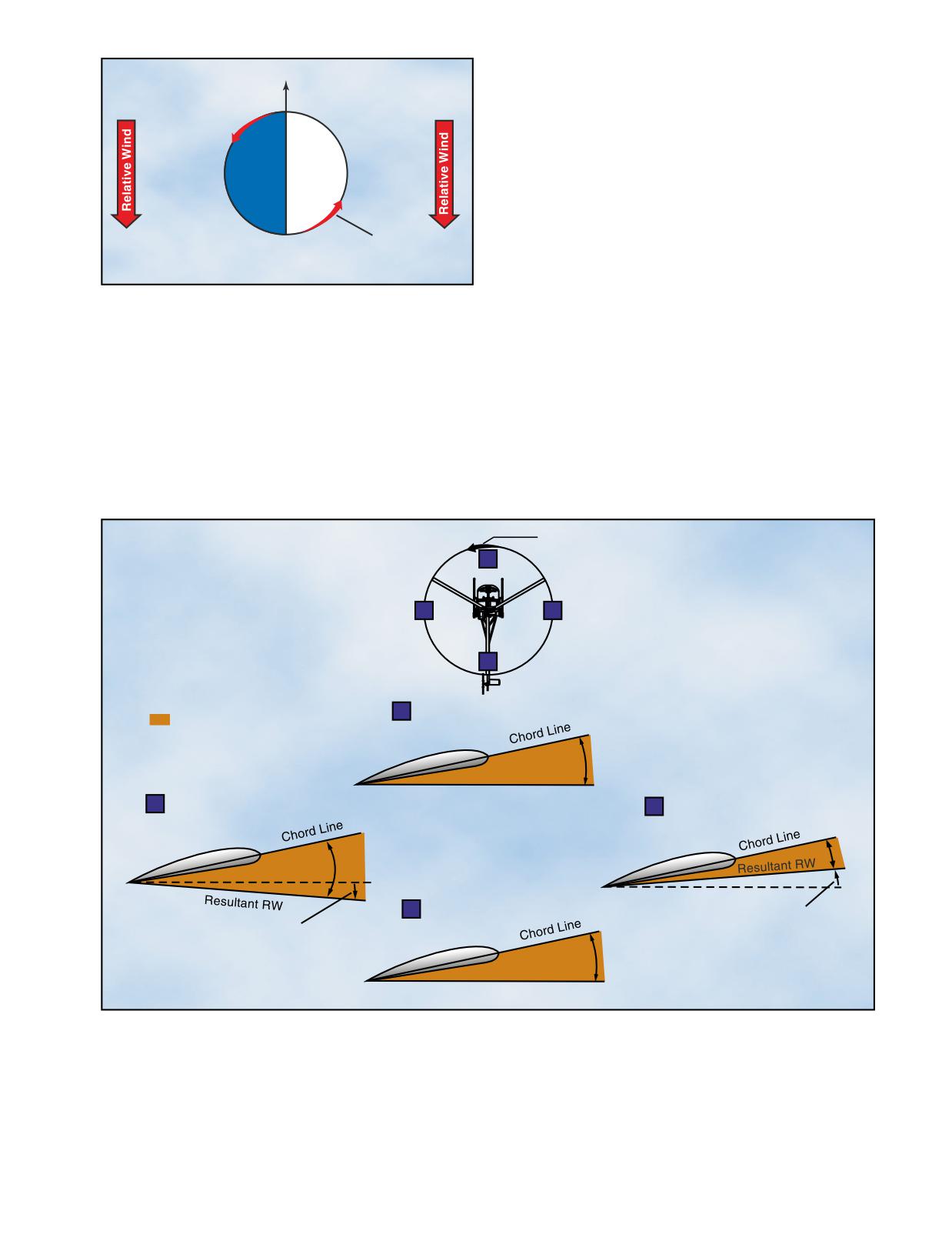
Figure 3-14. The blade tip speed of this helicopter is approxi-
called retreating blade stall and is evidenced by a nose
mately 300 knots. If the helicopter is moving forward at 100
pitch up, vibration, and a rolling tendency-usually to the
knots, the relative wind speed on the advancing side is 400
left in helicopters with counterclockwise blade rotation.
knots. On the retreating side, it is only 200 knots. This differ-
ence in speed causes a dissymmetry of lift.
You can avoid retreating blade stall by not exceeding
the never-exceed speed. This speed is designated VNE
As shown in figure 3-15, as the rotor blade reaches the
and is usually indicated on a placard and marked on the
advancing side of the rotor disc (A), it reaches its max-
airspeed indicator by a red line.
imum upflap velocity. When the blade flaps upward,
the angle between the chord line and the resultant rela-
During aerodynamic flapping of the rotor blades as they
tive wind decreases. This decreases the angle of attack,
compensate for dissymmetry of lift, the advancing blade
Direction of Rotation
B
C
A
D
RW = Relative Wind
B
Angle of Attack over
= Angle of Attack
Nose
Resultant RW
C
Angle of Attack at
A
Angle of Attack at
9 O'Clock Position
3 O'Clock Position
Angle of Attack over
D
Upflap Velocity
Tail
Downflap Velocity
Resultant RW
Figure 3-15. The combined upward flapping (reduced lift) of the advancing blade and downward flapping (increased lift) of the
retreating blade equalizes lift across the main rotor disc counteracting dissymmetry of lift.
VNE -The speed beyond which an aircraft should never be
operated. VNE can change with altitude, density altitude, and
weight.
3-7
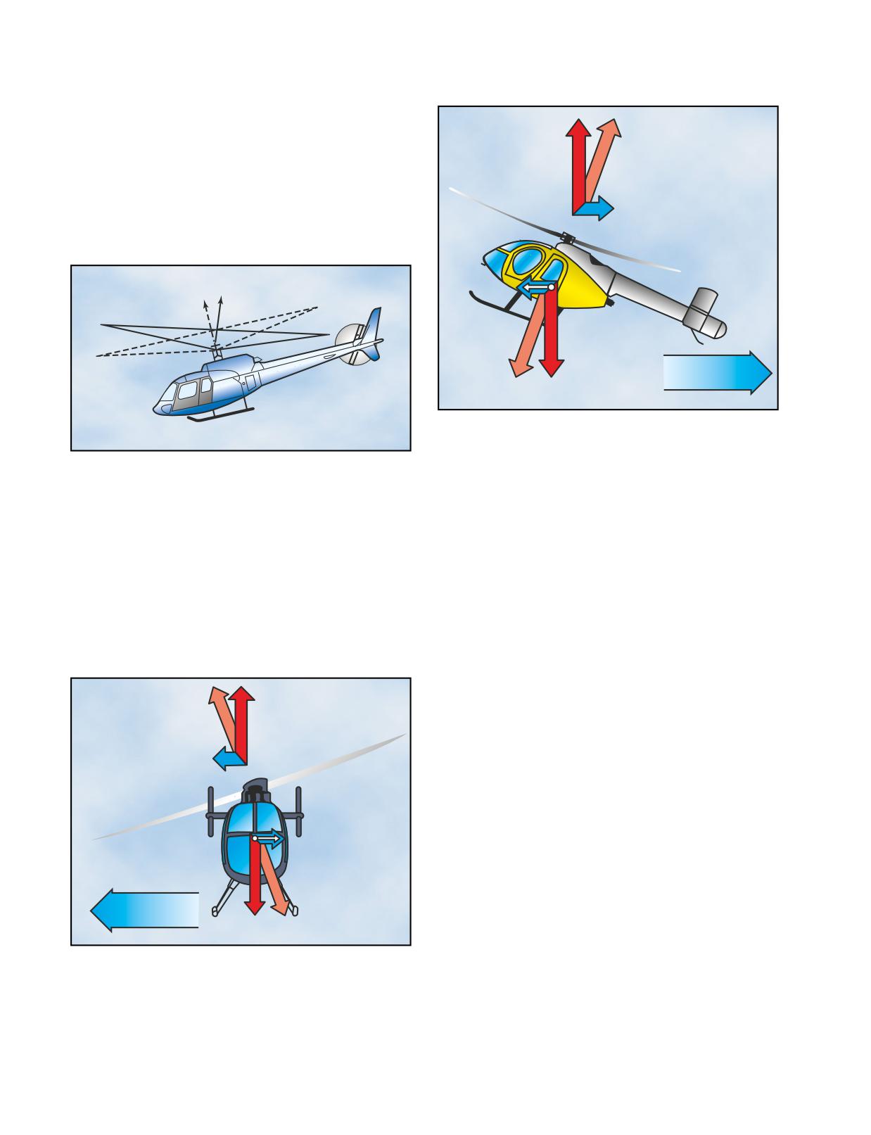
achieves maximum upflapping displacement over the
ward. Drag now acts forward with the lift component
nose and maximum downflapping displacement over the
straight up and weight straight down. [Figure 3-18]
tail. This causes the tip-path plane to tilt to the rear and is
referred to as blowback. Figure 3-16 shows how the rotor
Resultant
disc was originally oriented with the front down follow-
Lift
ing the initial cyclic input, but as airspeed is gained and
flapping eliminates dissymmetry of lift, the front of the
disc comes up, and the back of the disc goes down. This
reorientation of the rotor disc changes the direction in
Thrust
which total rotor thrust acts so that the helicopter’s for-
ward speed slows, but can be corrected with cyclic input.
Drag
Resultant
Helicopter
Movement
Weight
Figure 3-18. Forces acting on the helicopter during rearward
flight.
Figure 3-16. To compensate for blowback, you must move
TURNING FLIGHT
the cyclic forward. Blowback is more pronounced with higher
airspeeds.
In forward flight, the rotor disc is tilted forward, which
also tilts the total lift-thrust force of the rotor disc for-
ward. When the helicopter is banked, the rotor disc is
SIDEWARD FLIGHT
tilted sideward resulting in lift being separated into two
In sideward flight, the tip-path plane is tilted in the direc-
components. Lift acting upward and opposing weight is
tion that flight is desired. This tilts the total lift-thrust
called the vertical component of lift. Lift acting hori-
vector sideward. In this case, the vertical or lift compo-
zontally and opposing inertia (centrifugal force) is the
nent is still straight up and weight straight down, but the
horizontal component of lift (centripetal force).
horizontal or thrust component now acts sideward with
[Figure 3-19]
drag acting to the opposite side. [Figure 3-17]
As the angle of bank increases, the total lift force is tilted
Lift
more toward the horizontal, thus causing the rate of turn
Resultant
to increase because more lift is acting horizontally. Since
the resultant lifting force acts more horizontally, the
effect of lift acting vertically is deceased. To compen-
Thrust
sate for this decreased vertical lift, the angle of attack of
the rotor blades must be increased in order to maintain
altitude. The steeper the angle of bank, the greater the
angle of attack of the rotor blades required to maintain
altitude. Thus, with an increase in bank and a greater
Drag
angle of attack, the resultant lifting force increases and
the rate of turn is faster.
Helicopter
AUTOROTATION
Movement
Weight
Autorotation is the state of flight where the main rotor
system is being turned by the action of relative wind
Figure 3-17. Forces acting on the helicopter during sideward
flight.
REARWARD FLIGHT
Centripetal Force-The force
opposite centrifugal force and
For rearward flight, the tip-path plane is tilted rear-
attracts a body toward its axis of
ward, which, in turn, tilts the lift-thrust vector rear-
rotation.
3-8
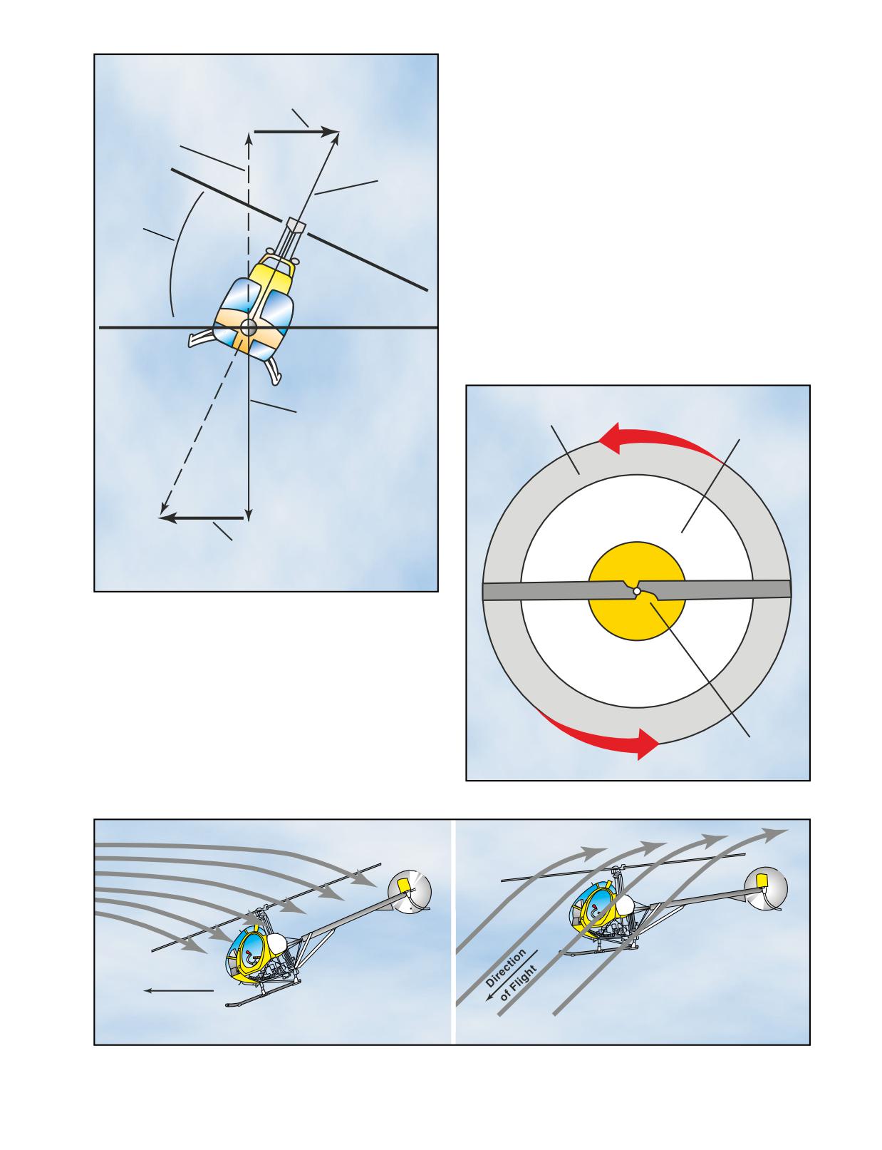
tinue turning even if the engine is not running. In nor-
mal powered flight, air is drawn into the main rotor sys-
Centripetal Force
(Horizontal Component of Lift)
tem from above and exhausted downward. During
Vertical
autorotation, airflow enters the rotor disc from below
Component
as the helicopter descends. [Figure 3-20]
of Lift
Resultant
AUTOROTATION (VERTICAL FLIGHT)
Lift
Most autorotations are performed with forward speed.
For simplicity, the following aerodynamic explanation
Bank
is based on a vertical autorotative descent (no forward
Angle
speed) in still air. Under these conditions, the forces
that cause the blades to turn are similar for all blades
regardless of their position in the plane of rotation.
Therefore, dissymmetry of lift resulting from helicop-
ter airspeed is not a factor.
During vertical autorotation, the rotor disc is divided
into three regions as illustrated in figure 3-21-the
Driven
Weight
Region 30%
Driving
Region 45%
Centrifugal
Force (Inertia)
Figure 3-19. The horizontal component of lift accelerates the
helicopter toward the center of the turn.
rather than engine power. It is the means by which a
helicopter can be landed safely in the event of an
engine failure. In this case, you are using altitude as
potential energy and converting it to kinetic energy dur-
ing the descent and touchdown. All helicopters must
Stall
have this capability in order to be certified.
Region 25%
Autorotation is permitted mechanically because of a
freewheeling unit, which allows the main rotor to con-
Figure 3-21. Blade regions in vertical autorotation descent.
Direction
of Flight
Normal Powered Flight
Autorotation
Figure 3-20. During an autorotation, the upward flow of relative wind permits the main rotor blades to rotate at their normal
speed. In effect, the blades are “gliding” in their rotational plane.
3-9
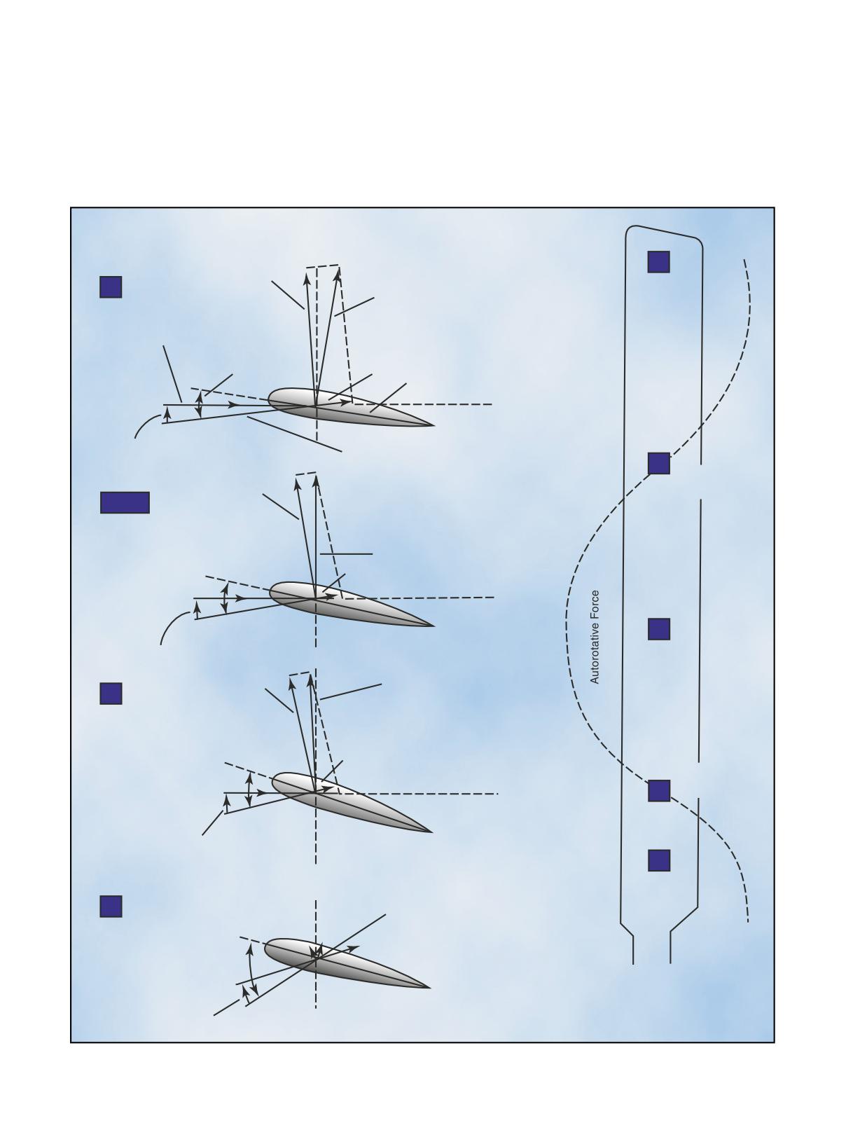
driven region, the driving region, and the stall region.
angle of attack in the driving region than in the driven
Figure 3-22 shows four blade sections that illustrate
region. The combination of the inflow up through the
force vectors. Part A is the driven region, B and D are
rotor with rotational relative wind produces different
points of equilibrium, part C is the driving region, and
combinations of aerodynamic force at every point
part E is the stall region. Force vectors are different in
along the blade.
each region because rotational relative wind is slower
near the blade root and increases continually toward
The driven region, also called the propeller region, is
the blade tip. Also, blade twist gives a more positive
nearest the blade tips. Normally, it consists of about 30
TAF
A
Lift
Total
Driven
A
Aerodynamic
Region
Force Aft
Drag
of Axis of
Rotational
Rotation
Relative Wind
Angle of
Attack 2°
Drag
Chord Line
Driven
Range
Resultant
Inflow Up
Relative Wind
Through Rotor
TAF
B
Point of
Lift
Equilibrium
B&D
Equilibrium
Drag
C
Driving
Inflow
TAF
Total
Region
Aerodynamic
Lift
Force Forward
C
of Axis of
Rotation
Drag
Driving
Angle of
Region
Point of
Attack 6°
Equilibrium
D
Inflow
E
Axis of
Stall
Rotation
Region
E
Drag
Lift
TAF
Stall
Drag
Region
Angle of
Attack 24°
(Blade is Stalled)
Inflow
Figure 3-22. Force vectors in vertical autorotation descent.
3-10
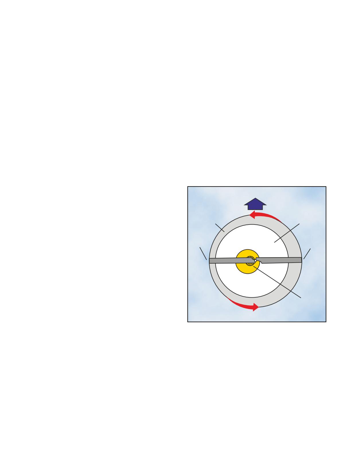
percent of the radius. In the driven region, part A of fig-
rotation of the blade. Part E of figure 3-22 depicts the
ure 3-22, the total aerodynamic force acts behind the
stall region.
axis of rotation, resulting in a overall drag force. The
driven region produces some lift, but that lift is offset
A constant rotor r.p.m. is achieved by adjusting the col-
by drag. The overall result is a deceleration in the rota-
lective pitch so blade acceleration forces from the driv-
tion of the blade. The size of this region varies with the
ing region are balanced with the deceleration forces
blade pitch, rate of descent, and rotor r.p.m. When
from the driven and stall regions.
changing autorotative r.p.m., blade pitch, or rate of
descent, the size of the driven region in relation to the
AUTOROTATION (FORWARD FLIGHT)
other regions also changes.
Autorotative force in forward flight is produced in
exactly the same manner as when the helicopter is
There are two points of equilibrium on the blade-one
descending vertically in still air. However, because for-
between the driven region and the driving region, and
ward speed changes the inflow of air up through the
one between the driving region and the stall region. At
rotor disc, all three regions move outboard along the
points of equilibrium, total aerodynamic force is
blade span on the retreating side of the disc where angle
aligned with the axis of rotation. Lift and drag are pro-
of attack is larger, as shown in figure 3-23. With lower
duced, but the total effect produces neither acceleration
angles of attack on the advancing side blade, more of
nor deceleration.
that blade falls in the driven region. On the retreating
side, more of the blade is in the stall region. A small
The driving region, or autorotative region, normally
section near the root experiences a reversed flow, there-
lies between 25 to 70 percent of the blade radius. Part
fore the size of the driven region on the retreating side
C of figure 3-22 shows the driving region of the blade,
is reduced.
which produces the forces needed to turn the blades
during autorotation. Total aerodynamic force in the
Forward
driving region is inclined slightly forward of the axis of
rotation, producing a continual acceleration force. This
inclination supplies thrust, which tends to accelerate
Driven
Driving
the rotation of the blade. Driving region size varies
Region
Region
with blade pitch setting, rate of descent, and rotor r.p.m.
Retreating
Advancing
By controlling the size of this region you can adjust
Side
Side
autorotative r.p.m. For example, if the collective pitch
is raised, the pitch angle increases in all regions. This
causes the point of equilibrium to move inboard along
the blade’s span, thus increasing the size of the driven
region. The stall region also becomes larger while the
driving region becomes smaller. Reducing the size of
the driving region causes the acceleration force of the
driving region and r.p.m. to decrease.
Stall
Region
The inner 25 percent of the rotor blade is referred to as
the stall region and operates above its maximum angle
of attack (stall angle) causing drag which tends to slow
Figure 3-23. Blade regions in forward autorotation descent.
3-11
3-12
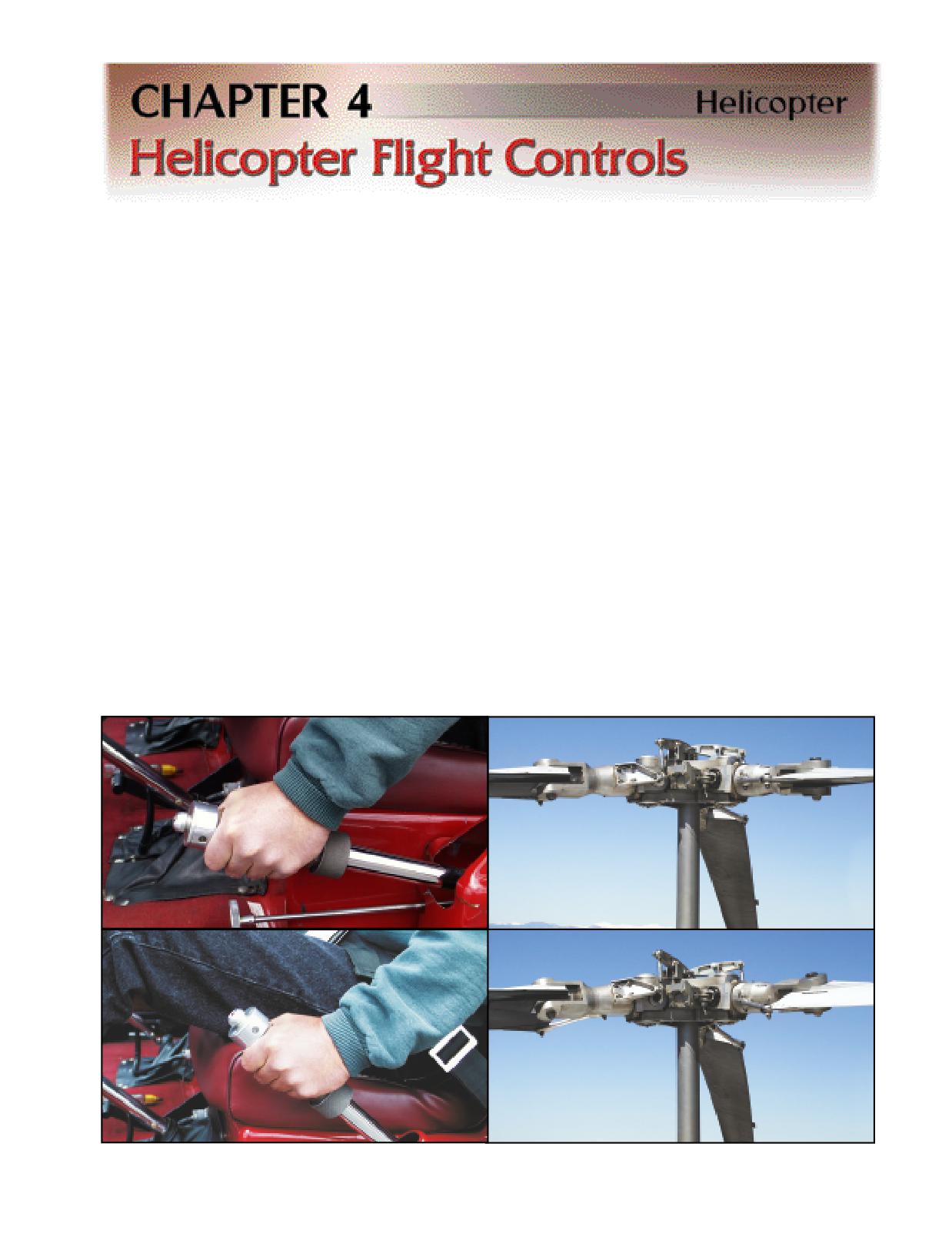
Note: In this chapter, it is assumed that the helicopter has
adjustable friction control helps prevent inadvertent
a counterclockwise main rotor blade rotation as viewed
collective pitch movement.
from above. If flying a helicopter with a clockwise rota-
tion, you will need to reverse left and right references,
Changing the pitch angle on the blades changes the
particularly in the areas of rotor blade pitch change, anti-
angle of attack on each blade. With a change in angle
torque pedal movement, and tail rotor thrust.
of attack comes a change in drag, which affects the
speed or r.p.m. of the main rotor. As the pitch angle
There are four basic controls used during flight. They
increases, angle of attack increases, drag increases,
are the collective pitch control, the throttle, the cyclic
and rotor r.p.m. decreases. Decreasing pitch angle
pitch control, and the antitorque pedals.
decreases both angle of attack and drag, while rotor
r.p.m. increases. In order to maintain a constant rotor
COLLECTIVE PITCH CONTROL
r.p.m., which is essential in helicopter operations, a
The collective pitch control, located on the left side of
proportionate change in power is required to com-
the pilot’s seat, changes the pitch angle of all main rotor
pensate for the change in drag. This is accomplished
blades simultaneously, or collectively, as the name
with the throttle control or a correlator and/or gover-
implies. As the collective pitch control is raised, there
nor, which automatically adjusts engine power.
is a simultaneous and equal increase in pitch angle of
all main rotor blades; as it is lowered, there is a simul-
THROTTLE CONTROL
taneous and equal decrease in pitch angle. This is done
The function of the throttle is to regulate engine r.p.m.
through a series of mechanical linkages and the amount
If the correlator or governor system does not maintain
of movement in the collective lever determines the
the desired r.p.m. when the collective is raised or low-
amount of blade pitch change. [Figure 4-1] An
ered, or if those systems are not installed, the throttle
Figure 4-1. Raising the collective pitch control increases the pitch angle the same amount on all blades.
4-1
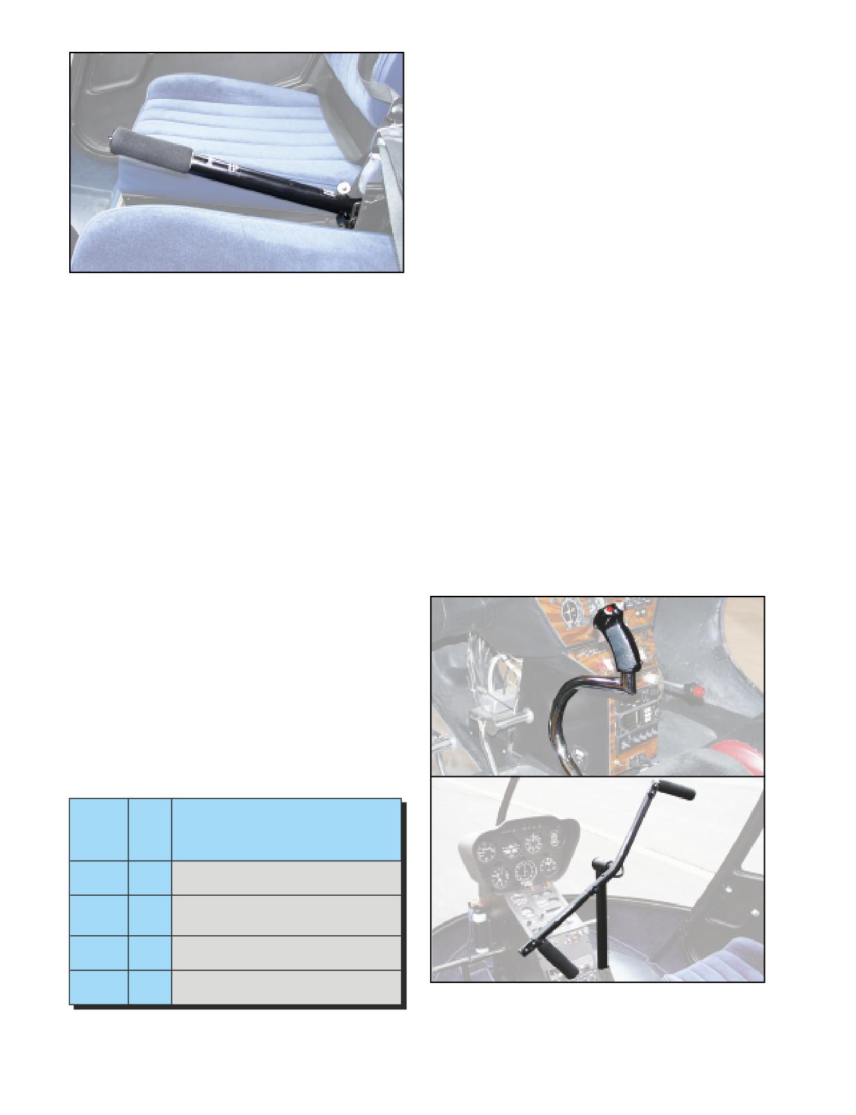
CORRELATOR / GOVERNOR
A correlator is a mechanical connection between the
collective lever and the engine throttle. When the col-
lective lever is raised, power is automatically increased
and when lowered, power is decreased. This system
maintains r.p.m. close to the desired value, but still
requires adjustment of the throttle for fine tuning.
A governor is a sensing device that senses rotor and
engine r.p.m. and makes the necessary adjustments in
order to keep rotor r.p.m. constant. In normal operations,
once the rotor r.p.m. is set, the governor keeps the r.p.m.
constant, and there is no need to make any throttle adjust-
Figure 4-2. A twist grip throttle is usually mounted on the end
ments. Governors are common on all turbine helicopters
of the collective lever. Some turbine helicopters have the
and used on some piston powered helicopters.
throttles mounted on the overhead panel or on the floor in
the cockpit.
Some helicopters do not have correlators or governors
and require coordination of all collective and throttle
movements. When the collective is raised, the throttle
has to be moved manually with the twist grip in order
must be increased; when the collective is lowered, the
to maintain r.p.m. Twisting the throttle outboard
throttle must be decreased. As with any aircraft control,
increases r.p.m.; twisting it inboard decreases r.p.m.
large adjustments of either collective pitch or throttle
[Figure 4-2]
should be avoided. All corrections should be made
through the use of smooth pressure.
COLLECTIVE PITCH / THROTTLE
CYCLIC PITCH CONTROL
COORDINATION
The cyclic pitch control tilts the main rotor disc by
When the collective pitch is raised, the load on the
changing the pitch angle of the rotor blades in their
engine is increased in order to maintain desired r.p.m.
cycle of rotation. When the main rotor disc is tilted, the
The load is measured by a manifold pressure gauge
horizontal component of lift moves the helicopter in
in piston helicopters or by a torque gauge in turbine
the direction of tilt. [Figure 4-4]
helicopters.
In piston helicopters, the collective pitch is the primary
control for manifold pressure, and the throttle is the pri-
mary control for r.p.m. However, the collective pitch
control also influences r.p.m., and the throttle also
influences manifold pressure; therefore, each is consid-
ered to be a secondary control of the other’s function.
Both the tachometer (r.p.m. indicator) and the manifold
pressure gauge must be analyzed to determine which
control to use. Figure 4-3 illustrates this relationship.
If
Manifold
and
Solution
Pressure
R.P.M.
is
is
Low
Low
Increasing the throttle increases manifold
pressure and r.p.m.
High
Low
Lowering the collective pitch decreases
manifold pressure and increases r.p.m.
Low
High
Raising the collective pitch increases
manifold pressure and decreases r.p.m.
High
High
Reducing the throttle decreases manifold
pressure and r.p.m.
Figure 4-4. The cyclic pitch control may be mounted verti-
cally between the pilot’s knees or on a teetering bar from a
Figure 4-3. Relationship between manifold pressure, r.p.m.,
single cyclic located in the center of the helicopter. The cyclic
collective, and throttle.
can pivot in all directions.
4-2
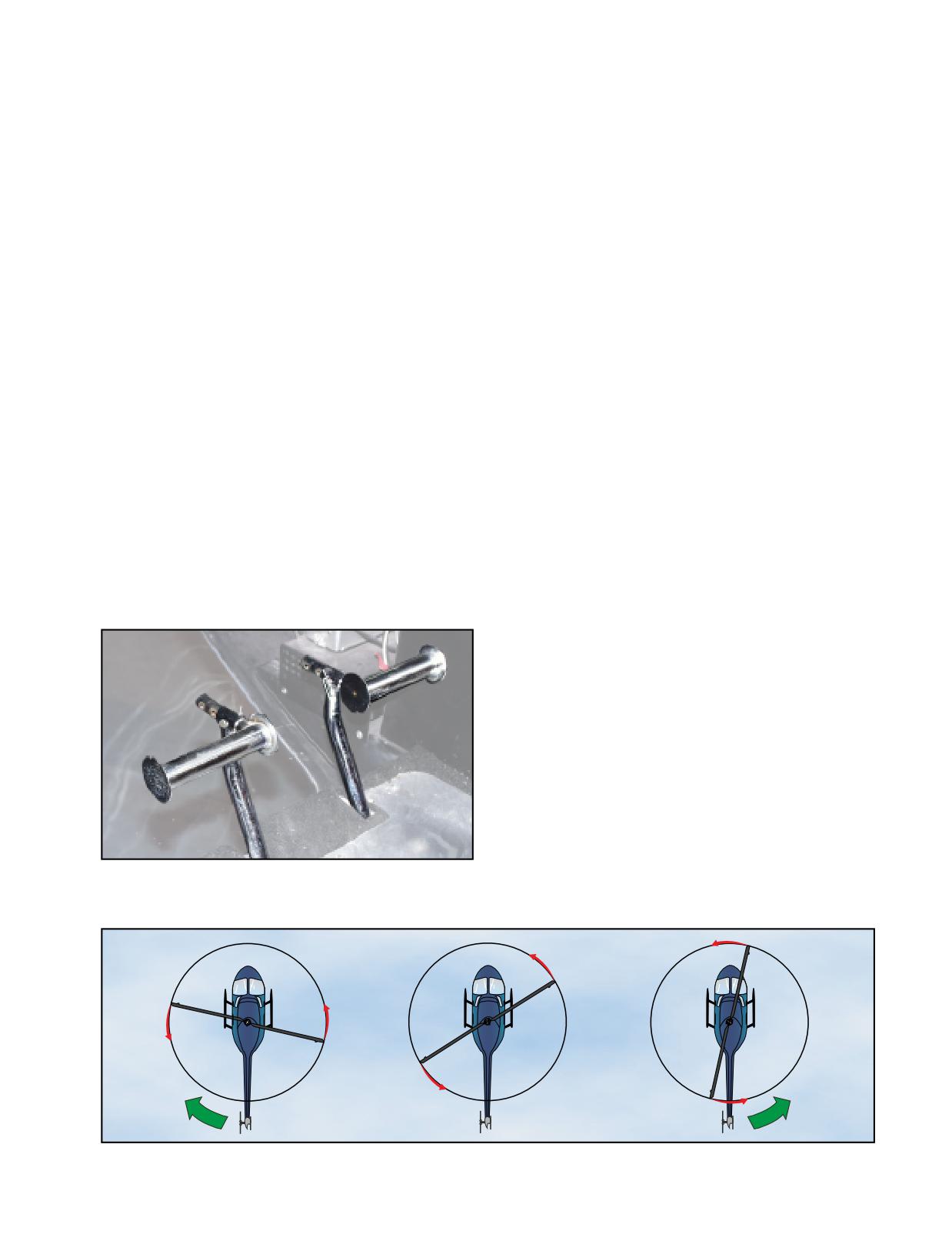
The rotor disc tilts in the direction that pressure is applied
HEADING CONTROL
to the cyclic pitch control. If the cyclic is moved forward,
Besides counteracting torque of the main rotor, the tail
the rotor disc tilts forward; if the cyclic is moved aft, the
rotor is also used to control the heading of the helicopter
disc tilts aft, and so on. Because the rotor disc acts like a
while hovering or when making hovering turns. Hovering
gyro, the mechanical linkages for the cyclic control rods
turns are commonly referred to as “pedal turns.”
are rigged in such a way that they decrease the pitch angle
of the rotor blade approximately 90° before it reaches the
In forward flight, the antitorque pedals are not used to
direction of cyclic displacement, and increase the pitch
control the heading of the helicopter, except during por-
angle of the rotor blade approximately 90° after it passes
tions of crosswind takeoffs and approaches. Instead they
the direction of displacement. An increase in pitch angle
are used to compensate for torque to put the helicopter in
increases angle of attack; a decrease in pitch angle
longitudinal trim so that coordinated flight can be main-
decreases angle of attack. For example, if the cyclic is
tained. The cyclic control is used to change heading by
moved forward, the angle of attack decreases as the rotor
making a turn to the desired direction.
blade passes the right side of the helicopter and increases
The thrust of the tail rotor depends on the pitch angle of
on the left side. This results in maximum downward
the tail rotor blades. This pitch angle can be positive, neg-
deflection of the rotor blade in front of the helicopter and
ative, or zero. A positive pitch angle tends to move the tail
maximum upward deflection behind it, causing the rotor
to the right. A negative pitch angle moves the tail to the
disc to tilt forward.
left, while no thrust is produced with a zero pitch angle.
ANTITORQUE PEDALS
With the right pedal moved forward of the neutral posi-
The antitorque pedals, located on the cabin floor by the
tion, the tail rotor either has a negative pitch angle or a
pilot’s feet, control the pitch, and therefore the thrust,
small positive pitch angle. The farther it is forward, the
of the tail rotor blades. [Figure 4-5] . The main purpose
larger the negative pitch angle. The nearer it is to neu-
of the tail rotor is to counteract the torque effect of the
tral, the more positive the pitch angle, and somewhere
main rotor. Since torque varies with changes in power,
in between, it has a zero pitch angle. As the left pedal is
the tail rotor thrust must also be varied. The pedals are
moved forward of the neutral position, the positive pitch
connected to the pitch change mechanism on the tail
angle of the tail rotor increases until it becomes maxi-
rotor gearbox and allow the pitch angle on the tail rotor
mum with full forward displacement of the left pedal.
blades to be increased or decreased.
If the tail rotor has a negative pitch angle, tail rotor
thrust is working in the same direction as the torque of
the main rotor. With a small positive pitch angle, the
tail rotor does not produce sufficient thrust to overcome
the torque effect of the main rotor during cruise flight.
Therefore, if the right pedal is displaced forward of
neutral during cruising flight, the tail rotor thrust does
not overcome the torque effect, and the nose yaws to
the right. [Figure 4-6]
With the antitorque pedals in the neutral position, the tail
rotor has a medium positive pitch angle. In medium pos-
itive pitch, the tail rotor thrust approximately equals the
Figure 4-5. Antitorque pedals compensate for changes in
torque of the main rotor during cruise flight, so the heli-
torque and control heading in a hover.
copter maintains a constant heading in level flight.
Negative or Low
Medium
High Positive
T
ail Moves
Positive Pitch
Positive Pitch
Pitch
Tail Moves
Figure 4-6. Tail rotor pitch angle and thrust in relation to pedal positions during cruising flight.
4-3
If the left pedal is in a forward position, the tail rotor
right pedal; the greater the power, the greater the forward
has a high positive pitch position. In this position, tail
displacement of the left pedal.
rotor thrust exceeds the thrust needed to overcome
torque effect during cruising flight so the helicopter
The maximum positive pitch angle of the tail rotor is
yaws to the left.
generally somewhat greater than the maximum nega-
The above explanation is based on cruise power and air-
tive pitch angle available. This is because the primary
speed. Since the amount of torque is dependent on the
purpose of the tail rotor is to counteract the torque of
amount of engine power being supplied to the main rotor,
the main rotor. The capability for tail rotors to produce
the relative positions of the pedals required to counteract
thrust to the left (negative pitch angle) is necessary,
torque depend upon the amount of power being used at
because during autorotation the drag of the transmis-
any time. In general, the less power being used, the
sion tends to yaw the nose to the left, or in the same
greater the requirement for forward displacement of the
direction the main rotor is turning.
4-4
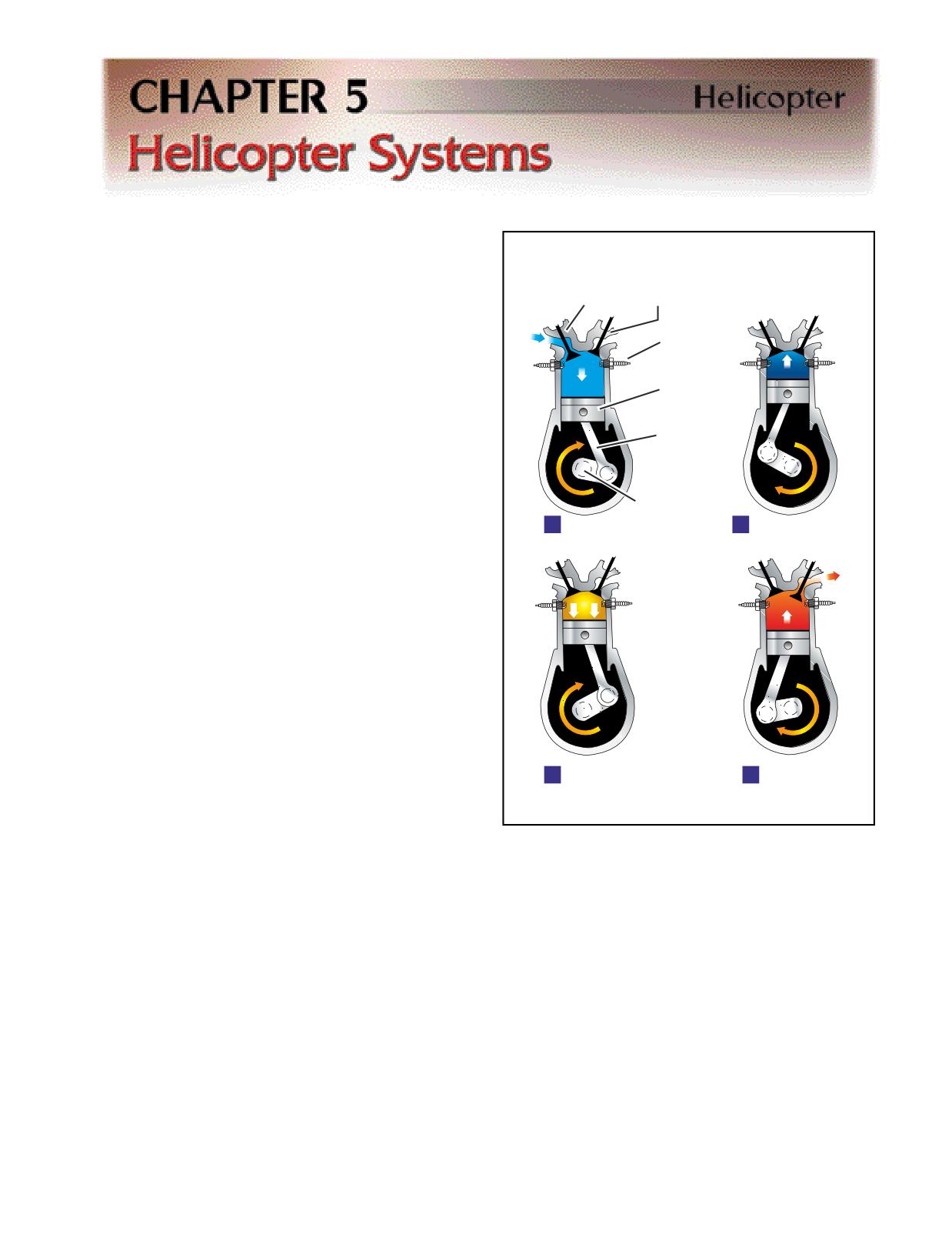
By knowing the various systems on a helicopter, you
will be able to more easily recognize potential problems,
and if a problem arises, you will have a better under-
Intake
Exhaust
standing of what to do to correct the situation.
Valve
Valve
Spark
ENGINES
Plug
The two most common types of engines used in heli-
copters are the reciprocating engine and the turbine
Piston
engine. Reciprocating engines, also called piston
engines, are generally used in smaller helicopters. Most
Connecting
Rod
training helicopters use reciprocating engines because
they are relatively simple and inexpensive to operate.
Turbine engines are more powerful and are used in a
wide variety of helicopters. They produce a tremen-
Crankshaft
dous amount of power for their size but are generally
1
Intake
2
Compression
more expensive to operate.
RECIPROCATING ENGINE
The reciprocating engine consists of a series of pistons
connected to a rotating crankshaft. As the pistons move
up and down, the crankshaft rotates. The reciprocating
engine gets its name from the back-and-forth movement
of its internal parts. The four-stroke engine is the most
common type, and refers to the four different cycles the
engine undergoes to produce power. [Figure 5-1]
When the piston moves away from the cylinder head on
3
Power
4
Exhaust
the intake stroke, the intake valve opens and a mixture
of fuel and air is drawn into the combustion chamber.
As the cylinder moves back towards the cylinder head,
the intake valve closes, and the fuel/air mixture is com-
Figure 5-1. The arrows in this illustration indicate the direc-
pressed. When compression is nearly complete, the
tion of motion of the crankshaft and piston during the four-
spark plugs fire and the compressed mixture is ignited
stroke cycle.
to begin the power stroke. The rapidly expanding gases
from the controlled burning of the fuel/air mixture
drive the piston away from the cylinder head, thus pro-
viding power to rotate the crankshaft. The piston then
TURBINE ENGINE
moves back toward the cylinder head on the exhaust
The gas turbine engine mounted on most helicopters is
stroke where the burned gasses are expelled through
made up of a compressor, combustion chamber, turbine,
the opened exhaust valve.
and gearbox assembly. The compressor compresses the
air, which is then fed into the combustion chamber
Even when the engine is operated at a fairly low speed,
where atomized fuel is injected into it. The fuel/air
the four-stroke cycle takes place several hundred times
mixture is ignited and allowed to expand. This com-
each minute. In a four-cylinder engine, each cylinder
bustion gas is then forced through a series of turbine
operates on a different stroke. Continuous rotation of a
wheels causing them to turn. These turbine wheels
crankshaft is maintained by the precise timing of the
provide power to both the engine compressor and the
power strokes in each cylinder.
main rotor system through an output shaft. The
5-1
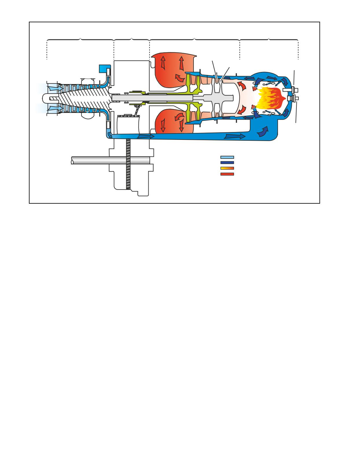
Compression Section
Gearbox Section
Turbine Section
Combustion Section
Exhaust Air Outlet
Stator
Rotor
Igniter Plug
Air
Gear
N2
Combustion
Compressor Rotor
Turbine to Compressor Coupling
N1
Liner
Inlet
Fuel Nozzle
Compressor Discharge Air Tube
Inlet Air
Output Shaft
Compressor Discharge Air
Combustion Gasses
Exhaust Gasses
Figure 5-2. Many helicopters use a turboshaft engine to drive the main transmission and rotor systems. The main difference
between a turboshaft and a turbojet engine is that most of the energy produced by the expanding gases is used to drive a tur-
bine rather than producing thrust through the expulsion of exhaust gases.
combustion gas is finally expelled through an exhaust
COMBUSTION CHAMBER
outlet. [Figure 5-2]
Unlike a piston engine, the combustion in a turbine
engine is continuous. An igniter plug serves only to
COMPRESSOR
ignite the fuel/air mixture when starting the engine.
The compressor may consist of an axial compressor, a
Once the fuel/air mixture is ignited, it will continue to
centrifugal compressor, or both. An axial compressor
burn as long as the fuel/air mixture continues to be
consists of two main elements, the rotor and the stator.
present. If there is an interruption of fuel, air, or both,
The rotor consists of a number of blades fixed on a
combustion ceases. This is known as a “flame-out,” and
rotating spindle and resembles a fan. As the rotor
the engine has to be restarted or re-lit. Some helicopters
turns, air is drawn rearwards. Stator vanes are arranged
are equipped with auto-relight, which automatically
in fixed rows between the rotor blades and act as a
activates the igniters to start combustion if the engine
diffuser at each stage to decrease air velocity and
flames out.
increase air pressure. There may be a number of rows
of rotor blades and stator vanes. Each row constitutes
a pressure stage, and the number of stages depends on
TURBINE
the amount of air and pressure rise required for the
The turbine section consists of a series of turbine
particular engine.
wheels that are used to drive the compressor section
and the rotor system. The first stage, which is usually
A centrifugal compressor consists of an impeller, dif-
referred to as the gas producer or N1 may consist of
fuser, and a manifold. The impeller, which is a forged
one or more turbine wheels. This stage drives the
disc with integral blades, rotates at a high speed to
components necessary to complete the turbine cycle
draw air in and expel it at an accelerated rate. The air
making the engine self-sustaining. Common compo-
then passes through the diffuser which slows the air
nents driven by the N1 stage are the compressor, oil
down. When the velocity of the air is slowed, static
pump, and fuel pump. The second stage, which may
pressure increases, resulting in compressed, high-pres-
also consist of one or more wheels, is dedicated to
sure air. The high pressure air then passes through the
driving the main rotor system and accessories from
compressor manifold where it is distributed to the
the engine gearbox. This is referred to as the power
combustion chamber.
turbine (N2 or Nr).
5-2
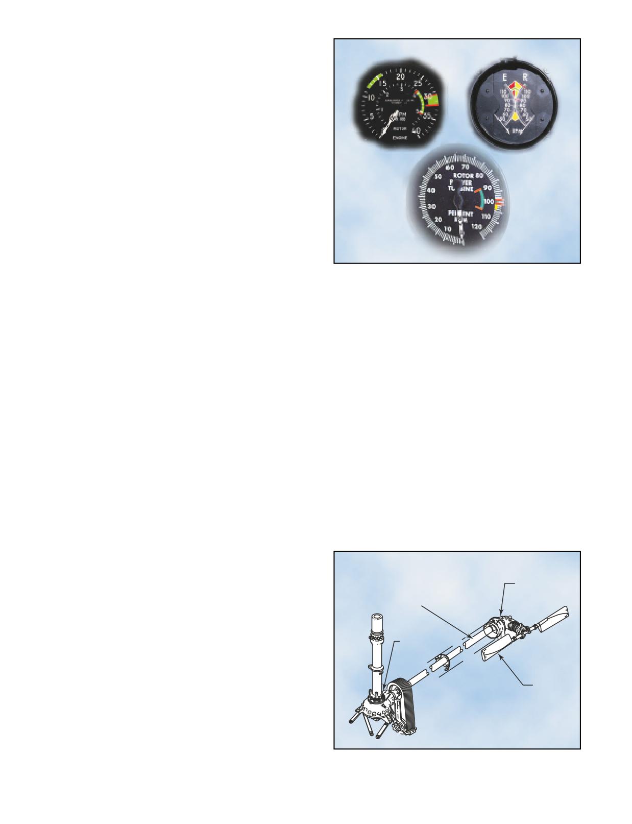
If the first and second stage turbines are mechanically cou-
pled to each other, the system is said to be a direct-drive
engine or fixed turbine. These engines share a common
shaft, which means the first and second stage turbines, and
thus the compressor and output shaft, are connected.
On most turbine assemblies used in helicopters, the
first stage and second stage turbines are not mechani-
cally connected to each other. Rather, they are mounted
on independent shafts and can turn freely with respect to
each other. This is referred to as a “free turbine.” When
the engine is running, the combustion gases pass
through the first stage turbine to drive the compressor
rotor, and then past the independent second stage tur-
bine, which turns the gearbox to drive the output shaft.
TRANSMISSION SYSTEM
The transmission system transfers power from the
engine to the main rotor, tail rotor, and other acces-
Figure 5-3. There are various types of dual-needle tachome-
sories. The main components of the transmission sys-
ters, however, when the needles are superimposed or married,
the ratio of the engine r.p.m. is the same as the gear reduction
tem are the main rotor transmission, tail rotor drive
ratio.
system, clutch, and freewheeling unit. Helicopter trans-
missions are normally lubricated and cooled with their
own oil supply. A sight gauge is provided to check the
In helicopters with horizontally mounted engines,
oil level. Some transmissions have chip detectors
another purpose of the main rotor transmission is to
located in the sump. These detectors are wired to warn-
change the axis of rotation from the horizontal axis of
ing lights located on the pilot’s instrument panel that
the engine to the vertical axis of the rotor shaft.
illuminate in the event of an internal problem.
TAIL ROTOR DRIVE SYSTEM
MAIN ROTOR TRANSMISSION
The tail rotor drive system consists of a tail rotor drive
The primary purpose of the main rotor transmission
shaft powered from the main transmission and a tail
is to reduce engine output r.p.m. to optimum rotor
rotor transmission mounted at the end of the tail boom.
r.p.m. This reduction is different for the various heli-
The drive shaft may consist of one long shaft or a series
copters, but as an example, suppose the engine r.p.m. of
of shorter shafts connected at both ends with flexible
a specific helicopter is 2,700. To achieve a rotor speed of
couplings. This allows the drive shaft to flex with the
450 r.p.m. would require a 6 to 1 reduction. A 9 to 1
tail boom. The tail rotor transmission provides a right
reduction would mean the rotor would turn at
angle drive for the tail rotor and may also include gear-
300 r.p.m.
ing to adjust the output to optimum tail rotor r.p.m.
[Figure 5-4]
Most helicopters use a dual-needle tachometer to show
both engine and rotor r.p.m. or a percentage of engine
and rotor r.p.m. The rotor r.p.m. needle normally is
Tail Rotor
used only during clutch engagement to monitor rotor
Transmission
acceleration, and in autorotation to maintain r.p.m.
Drive Shaft
within prescribed limits. [Figure 5-3]
Main
Transmission
Chip Detector-A chip detector is
a warning device that alerts you to
any abnormal wear in a transmis-
Tail Rotor
sion or engine. It consists of a
magnetic plug located within the
transmission. The magnet attracts
any ferrous metal particles that
have come loose from the bearings
or other transmission parts. Most
chip detectors send a signal to
lights located on the instrument
panel that illuminate when ferrous
Figure 5-4. The typical components of a tail rotor drive sys-
metal particles are picked up.
tem are shown here.
5-3
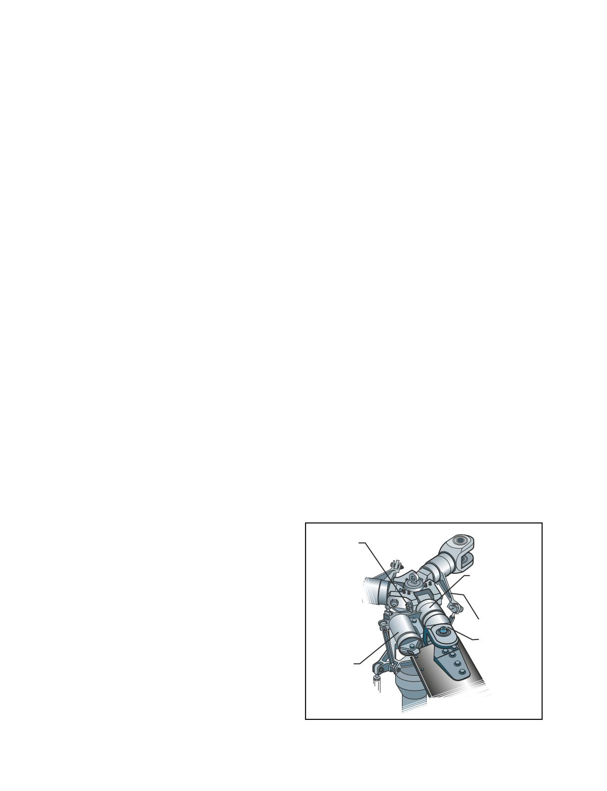
CLUTCH
Advantages of this system include vibration isolation,
In a conventional airplane, the engine and propeller are
simple maintenance, and the ability to start and warm
permanently connected. However, in a helicopter there
up the engine without engaging the rotor.
is a different relationship between the engine and the
FREEWHEELING UNIT
rotor. Because of the greater weight of a rotor in rela-
Since lift in a helicopter is provided by rotating airfoils,
tion to the power of the engine, as compared to the
these airfoils must be free to rotate if the engine fails. The
weight of a propeller and the power in an airplane, the
freewheeling unit automatically disengages the engine
rotor must be disconnected from the engine when you
from the main rotor when engine r.p.m. is less than main
engage the starter. A clutch allows the engine to be
rotor r.p.m. This allows the main rotor to continue turning
started and then gradually pick up the load of the rotor.
at normal in-flight speeds. The most common freewheel-
On free turbine engines, no clutch is required, as the
ing unit assembly consists of a one-way sprag clutch
gas producer turbine is essentially disconnected from
located between the engine and main rotor transmission.
the power turbine. When the engine is started, there is
This is usually in the upper pulley in a piston helicopter
little resistance from the power turbine. This enables
or mounted on the engine gearbox in a turbine helicopter.
the gas producer turbine to accelerate to normal idle
When the engine is driving the rotor, inclined surfaces in
speed without the load of the transmission and rotor
the spray clutch force rollers against an outer drum. This
system dragging it down. As the gas pressure increases
prevents the engine from exceeding transmission r.p.m. If
through the power turbine, the rotor blades begin to
the engine fails, the rollers move inward, allowing the
turn, slowly at first and then gradually accelerate to
outer drum to exceed the speed of the inner portion. The
normal operating r.p.m.
transmission can then exceed the speed of the engine. In
this condition, engine speed is less than that of the drive
On reciprocating helicopters, the two main types of
system, and the helicopter is in an autorotative state.
clutches are the centrifugal clutch and the belt drive clutch.
CENTRIFUGAL CLUTCH
MAIN ROTOR SYSTEM
The centrifugal clutch is made up of an inner assembly
Main rotor systems are classified according to how the
and a outer drum. The inner assembly, which is con-
main rotor blades move relative to the main rotor hub.
nected to the engine driveshaft, consists of shoes lined
As was described in Chapter 1-Introduction to the
with material similar to automotive brake linings. At
Helicopter, there are three basic classifications: fully
low engine speeds, springs hold the shoes in, so there is
articulated, semirigid, or rigid. Some modern rotor sys-
no contact with the outer drum, which is attached to the
tems use a combination of these types.
transmission input shaft. As engine speed increases,
centrifugal force causes the clutch shoes to move out-
FULLY ARTICULATED ROTOR SYSTEM
ward and begin sliding against the outer drum. The
In a fully articulated rotor system, each rotor blade is
transmission input shaft begins to rotate, causing the
attached to the rotor hub through a series of hinges,
rotor to turn, slowly at first, but increasing as the friction
which allow the blade to move independently of the
increases between the clutch shoes and transmission
others. These rotor systems usually have three or more
drum. As rotor speed increases, the rotor tachometer
blades. [Figure 5-5]
needle shows an increase by moving toward the engine
tachometer needle. When the two needles are superim-
posed, the engine and the rotor are synchronized,
Flapping
indicating the clutch is fully engaged and there is no
Hinge
further slippage of the clutch shoes.
Pitch Change
BELT DRIVE CLUTCH
Axis
Some helicopters utilize a belt drive to transmit power
(Feathering)
from the engine to the transmission. A belt drive con-
sists of a lower pulley attached to the engine, an upper
Pitch Horn
pulley attached to the transmission input shaft, a belt
or a series of V-belts, and some means of applying
Drag Hinge
tension to the belts. The belts fit loosely over the
Damper
upper and lower pulley when there is no tension on
the belts. This allows the engine to be started without
any load from the transmission. Once the engine is
running, tension on the belts is gradually increased.
When the rotor and engine tachometer needles are
superimposed, the rotor and the engine are synchro-
Figure 5-5. Each blade of a fully articulated rotor system can
nized, and the clutch is then fully engaged.
flap, drag, and feather independently of the other blades.
5-4
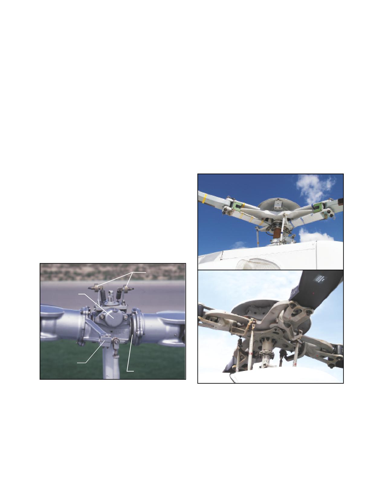
The horizontal hinge, called the flapping hinge, allows
they can be feathered. Flapping and lead/lag forces are
the blade to move up and down. This movement is
absorbed by blade bending.
called flapping and is designed to compensate for dis-
symetry of lift. The flapping hinge may be located at
COMBINATION ROTOR SYSTEMS
varying distances from the rotor hub, and there may be
Modern rotor systems may use the combined princi-
more than one hinge.
ples of the rotor systems mentioned above. Some
rotor hubs incorporate a flexible hub, which allows
The vertical hinge, called the lead-lag or drag hinge,
for blade bending (flexing) without the need for bear-
allows the blade to move back and forth. This move-
ings or hinges. These systems, called flextures, are
ment is called lead-lag, dragging, or hunting.
usually constructed from composite material.
Dampers are usually used to prevent excess back
Elastomeric bearings may also be used in place of
and forth movement around the drag hinge. The pur-
conventional roller bearings. Elastomeric bearings are
pose of the drag hinge and dampers is to compensate
bearings constructed from a rubber type material and
for the acceleration and deceleration caused by
have limited movement that is perfectly suited for hel-
Coriolis Effect.
icopter applications. Flextures and elastomeric bear-
ings require no lubrication and, therefore, require less
Each blade can also be feathered, that is, rotated around
maintenance. They also absorb vibration, which
its spanwise axis. Feathering the blade means changing
means less fatigue and longer service life for the heli-
the pitch angle of the blade. By changing the pitch
copter components. [Figure 5-7]
angle of the blades you can control the thrust and direc-
tion of the main rotor disc.
SEMIRIGID ROTOR SYSTEM
A semirigid rotor system is usually composed of two
blades which are rigidly mounted to the main rotor hub.
The main rotor hub is free to tilt with respect to the
main rotor shaft on what is known as a teetering
hinge. This allows the blades to flap together as a
unit. As one blade flaps up, the other flaps down.
Since there is no vertical drag hinge, lead-lag forces
are absorbed through blade bending. [Figure 5-6]
Static Stops
Teetering
Hinge
Pitch Horn
Feathering Hinge
Figure 5-6. On a semirigid rotor system, a teetering hinge
allows the rotor hub and blades to flap as a unit. A static flap-
Figure 5-7. Rotor systems, such as Eurocopter’s Starflex or
ping stop located above the hub prevents excess rocking
Bell’s soft-in-plane, use composite material and elastomeric
when the blades are stopped. As the blades begin to turn,
bearings to reduce complexity and maintenance and,
centrifugal force pulls the static stops out of the way.
thereby, increase reliability.
RIGID ROTOR SYSTEM
SWASH PLATE ASSEMBLY
In a rigid rotor system, the blades, hub, and mast are
The purpose of the swash plate is to transmit control
rigid with respect to each other. There are no vertical or
inputs from the collective and cyclic controls to the main
horizontal hinges so the blades cannot flap or drag, but
rotor blades. It consists of two main parts: the stationary
5-5
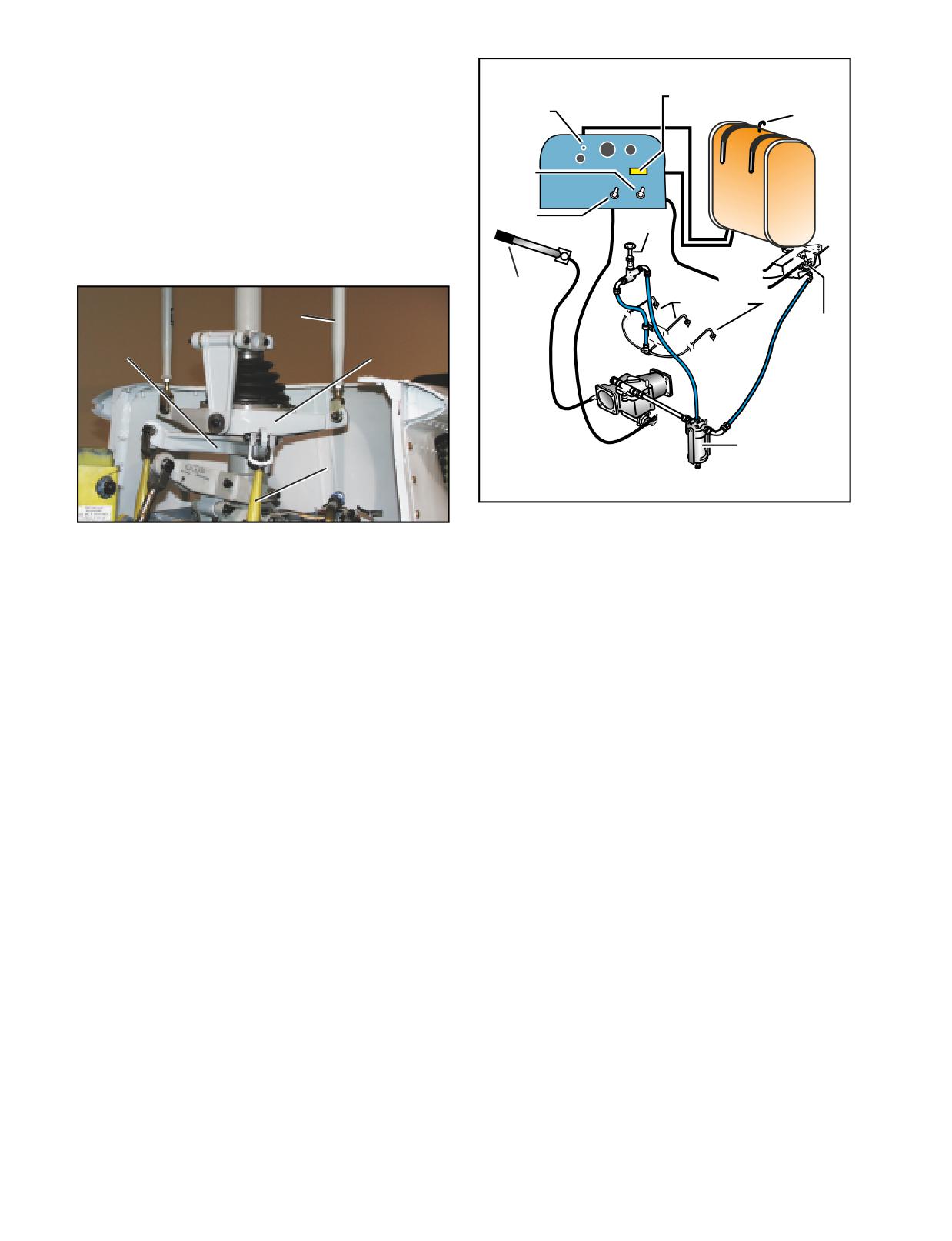
swash plate and the rotating swash plate. [Figure 5-8]
The stationary swash plate is mounted around the main
Low Level
Fuel Quantity
rotor mast and connected to the cyclic and collective
Warning
Gauge
Vent
controls by a series of pushrods. It is restrained from
Light
rotating but is able to tilt in all directions and move verti-
Fuel
cally. The rotating swash plate is mounted to the sta-
Shutoff
tionary swash plate by means of a bearing and is
Tank
allowed to rotate with the main rotor mast. Both swash
Mixture
Control
plates tilt and slide up and down as one unit. The rotat-
Primer
ing swash plate is connected to the pitch horns by the
pitch links.
Throttle
Primer Nozzle
Pitch
at Cylinder
Link
Stationary
Shut-off
Rotating
Valve
Swash
Swash
Plate
Plate
Carburetor
Fuel
Control
Strainer
Rod
Figure 5-9. A typical gravity feed fuel system, in a helicopter
with a reciprocating engine, contains the components
Figure 5-8. Collective and cyclic control inputs are transmit-
shown here.
ted to the stationary swash plate by control rods causing it to
tilt or to slide vertically. The pitch links attached from the
rotating swash plate to the pitch horns on the rotor hub
flow to the engine in the event of an emergency or fire.
transmit these movements to the blades.
The shut-off valve remains in the open position for all
normal operations.
Most non-gravity feed fuel systems contain both an
FUEL SYSTEMS
electric pump and a mechanical engine driven pump.
The fuel system in a helicopter is made up of two
The electrical pump is used to maintain positive fuel
groups of components: the fuel supply system and the
pressure to the engine pump and also serves as a
engine fuel control system.
backup in the event of mechanical pump failure. The
electrical pump is controlled by a switch in the cockpit.
FUEL SUPPLY SYSTEM
The engine driven pump is the primary pump that sup-
The supply system consists of a fuel tank or tanks, fuel
plies fuel to the engine and operates any time the
quantity gauges, a shut-off valve, fuel filter, a fuel line
engine is running.
to the engine, and possibly a primer and fuel pumps.
[Figure 5-9]
A fuel filter removes moisture and other sediment from
the fuel before it reaches the engine. These contami-
The fuel tanks are usually mounted to the airframe as
nants are usually heavier than fuel and settle to the bot-
close as possible to the center of gravity. This way, as
tom of the fuel filter sump where they can be drained
fuel is burned off, there is a negligible effect on the cen-
out by the pilot.
ter of gravity. A drain valve located on the bottom of
the fuel tank allows the pilot to drain water and sedi-
Some fuel systems contain a small hand-operated pump
ment that may have collected in the tank. A fuel vent
called a primer. A primer allows fuel to be pumped
prevents the formation of a vacuum in the tank, and an
directly into the intake port of the cylinders prior to
overflow drain allows for fuel to expand without rup-
engine start. The primer is useful in cold weather when
turing the tank. A fuel quantity gauge located on the
fuel in the carburetor is difficult to vaporize.
pilot’s instrument panel shows the amount of fuel
measured by a sensing unit inside the tank. Some
gauges show tank capacity in both gallons and pounds.
ENGINE FUEL CONTROL SYSTEM
The purpose of the fuel control system is to bring out-
The fuel travels from the fuel tank through a shut-off
side air into the engine, mix it with fuel in the proper
valve, which provides a means to completely stop fuel
proportion, and deliver it to the combustion chamber.
5-6
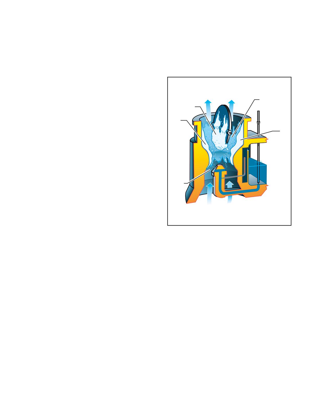
RECIPROCATING ENGINES
days with temperatures as high as 38°C (100°F) and
Fuel is delivered to the cylinders by either a carburetor
the humidity as low as 50 percent. However, it is more
or fuel injection system.
likely to occur when temperatures are below 21°C
(70°F) and the relative humidity is above 80 percent.
The likelihood of icing increases as temperature
CARBURETOR
decreases down to 0°C (32°F), and as relative humidity
In a carburetor system, air is mixed with vaporized fuel as
increases. Below freezing, the possibility of carburetor
it passes through a venturi in the carburetor. The metered
icing decreases with decreasing temperatures.
fuel/air mixture is then delivered to the cylinder intake.
Carburetors are calibrated at sea level, and the correct
fuel-to-air mixture ratio is established at that altitude
Fuel/Air
To Engine
with the mixture control set in the FULL RICH posi-
Mixture
tion. However, as altitude increases, the density of air
Ice
entering the carburetor decreases while the density of
the fuel remains the same. This means that at higher
Ice
altitudes, the mixture becomes progressively richer. To
maintain the correct fuel/air mixture, you must be able
Ice
to adjust the amount of fuel that is mixed with the
incoming air. This is the function of the mixture con-
trol. This adjustment, often referred to as “leaning the
mixture,” varies from one aircraft to another. Refer to
the FAA-Approved Rotocraft Flight Manual (RFM) to
determine specific procedures for your helicopter. Note
that most manufacturers do not recommend leaning hel-
icopters in-flight.
Venturi
Most mixture adjustments are required during changes of
altitude or during operations at airports with field eleva-
tions well above sea level. A mixture that is too rich can
Incoming Air
result in engine roughness and reduced power. The rough-
ness normally is due to spark plug fouling from exces-
sive carbon buildup on the plugs. This occurs because
Figure 5-10. Carburetor ice reduces the size of the air pas-
the excessively rich mixture lowers the temperature inside
sage to the engine. This restricts the flow of the fuel/air
the cylinder, inhibiting complete combustion of the fuel.
mixture, and reduces power.
This condition may occur during the pretakeoff runup at
high elevation airports and during climbs or cruise flight
at high altitudes. Usually, you can correct the problem by
Although carburetor ice can occur during any phase of
leaning the mixture according to RFM instructions.
flight, it is particularly dangerous when you are using
reduced power, such as during a descent. You may not
If you fail to enrich the mixture during a descent from
notice it during the descent until you try to add power.
high altitude, it normally becomes too lean. High
engine temperatures can cause excessive engine wear
Indications of carburetor icing are a decrease in engine
or even failure. The best way to avoid this type of situ-
r.p.m. or manifold pressure, the carburetor air tempera-
ation is to monitor the engine temperature gauges regu-
ture gauge indicating a temperature outside the safe
larly and follow the manufacturer’s guidelines for
operating range, and engine roughness. Since changes
maintaining the proper mixture.
in r.p.m. or manifold pressure can occur for a number
of reasons, it is best to closely check the carburetor air
CARBURETOR ICE
temperature gauge when in possible carburetor icing
The effect of fuel vaporization and decreasing air pres-
conditions. Carburetor air temperature gauges are
sure in the venturi causes a sharp drop in temperature
marked with a yellow caution arc or green operating
in the carburetor. If the air is moist, the water vapor in
arcs. You should refer to the FAA-Approved Rotorcraft
the air may condense. When the temperature in the car-
Flight Manual for the specific procedure as to when
buretor is at or below freezing, carburetor ice may form
and how to apply carburetor heat. However, in most
on internal surfaces, including the throttle valve.
cases, you should keep the needle out of the yellow arc
[Figure 5-10] Because of the sudden cooling that takes
or in the green arc. This is accomplished by using a car-
place in the carburetor, icing can occur even on warm
buretor heat system, which eliminates the ice by
5-7
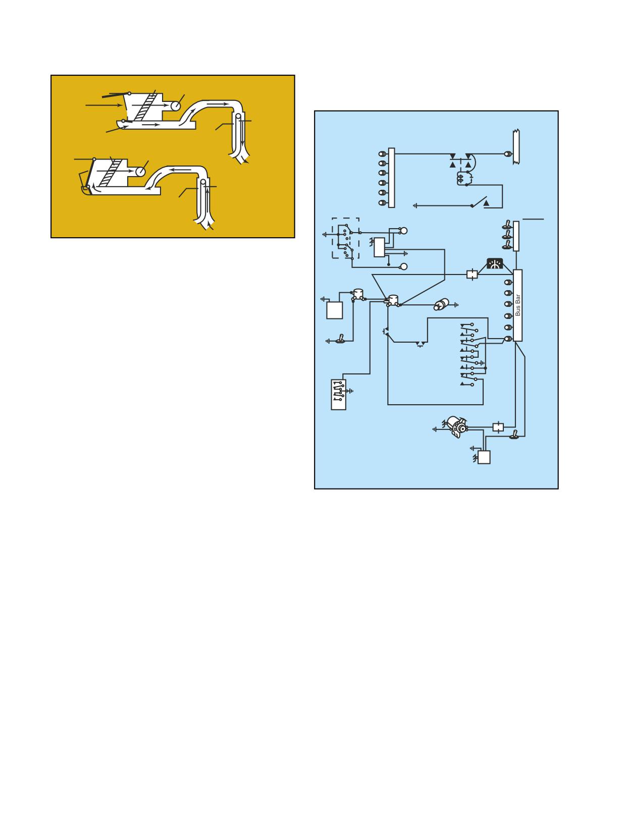
routing air across a heat source, such as an exhaust
driven alternator. These alternators have advantages
manifold, before it enters the carburetor. [Figure 5-11].
over older style generators as they are lighter in
weight, require lower maintenance, and maintain a
uniform electrical output even at low engine r.p.m.
Filter
To Carb
[Figure 5-12]
Door
Manifold
Pipe
(Optional Avionics)
Carb Heat
Avionic
Avionic
Carb Heat Off
Bus
Collector
Avionics Relay
Bus
Filter
Bar
To Carb
Door
Manifold
Heated Air
On
Pipe
Carb Heat On
Carb Heat
Off
Collector
Mag Switch
Avionics Master
Lights
Off
Ret
Switch
L
L
Left
Panel
G
R
Adv
Magneto
Position
Both
Figure 5-11. When you turn the carburetor heat ON, normal
Beacon
Ammeter
air flow is blocked, and heated air from an alternate source
R
Starting
Right
Vibrator
flows through the filter to the carburetor.
Adv
Magneto
Battery
Relay
Starter
Trim
Engine
Relay
Starter
Instr
FUEL INJECTION
-
+
Lndg Lt
In a fuel injection system, fuel and air are metered at
24V
Radio
the fuel control unit but are not mixed. The fuel is
Battery
Starter
Release
Xpdr
Switch
injected directly into the intake port of the cylinder
Clutch
Hold
where it is mixed with the air just before entering the
Battery
M/R Gearbox
Switch
cylinder. This system ensures a more even fuel distri-
Press Switch
bution in the cylinders and better vaporization, which
Engage
in turn, promotes more efficient use of fuel. Also, the
Clutch
fuel injection system eliminates the problem of carbu-
Switch
retor icing and the need for a carburetor heat system.
Clutch Actuator
Alternator
-
(Internal Limit Switches
+
Shown in Full
F2
F1
TURBINE ENGINES
Disengage Position)
Alternator
The fuel control system on the turbine engine is fairly
Switch
complex, as it monitors and adjusts many different
Alternator
parameters on the engine. These adjustments are done
Control Unit
automatically and no action is required of the pilot
other than starting and shutting down. No mixture
Figure 5-12. An electrical system scematic like this sample is
adjustment is necessary, and operation is fairly simple
included in most POHs. Notice that the various bus bar
accessories are protected by circuit breakers. However, you
as far as the pilot is concerned. New generation fuel
should still make sure all electrical equipment is turned off
controls incorporate the use of a full authority digital
before you start the engine. This protects sensitive compo-
engine control (FADEC) computer to control the
nents, particularly the radios, from damage which may be
engine’s fuel requirements. The FADEC systems
caused by random voltages generated during the starting
increase efficiency, reduce engine wear, and also
process.
reduce pilot workload. The FADEC usually incorpo-
rates back-up systems in the event of computer failure.
Turbine powered helicopters use a starter/generator
system. The starter/generator is permanently coupled
ELECTRICAL SYSTEMS
to the engine gearbox. When starting the engine, elec-
The electrical systems, in most helicopters, reflect the
trical power from the battery is supplied to the
increased use of sophisticated avionics and other elec-
starter/generator, which turns the engine over. Once the
trical accessories. More and more operations in today’s
engine is running, the starter/generator is driven by the
flight environment are dependent on the aircraft’s elec-
engine and is then used as a generator.
trical system; however, all helicopters can be safely
flown without any electrical power in the event of an
Current from the alternator or generator is delivered
electrical malfunction or emergency.
through a voltage regulator to a bus bar. The voltage
Helicopters have either a 14- or 28-volt, direct-cur-
regulator maintains the constant voltage required by
rent electrical system. On small, piston powered
the electrical system by regulating the output of the
helicopters, electrical energy is supplied by an engine-
alternator or generator. An over-voltage control may be
5-8
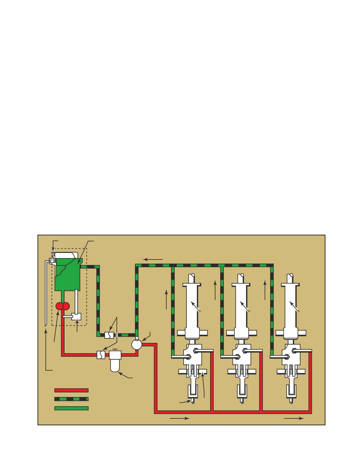
incorporated to prevent excessive voltage, which may
expect. Loss of the alternator or generator causes the
damage the electrical components. The bus bar serves
loadmeter to indicate zero.
to distribute the current to the various electrical com-
ponents of the helicopter.
Electrical switches are used to select electrical compo-
nents. Power may be supplied directly to the component
A battery is mainly used for starting the engine. In
or to a relay, which in turn provides power to the
addition, it permits limited operation of electrical
component. Relays are used when high current and/or
components, such as radios and lights, without the
heavy electrical cables are required for a particular com-
engine running. The battery is also a valuable source
ponent, which may exceed the capacity of the switch.
of standby or emergency electrical power in the event
of alternator or generator failure.
Circuit breakers or fuses are used to protect various
electrical components from overload. A circuit breaker
An ammeter or loadmeter is used to monitor the
pops out when its respective component is overloaded.
electrical current within the system. The ammeter
The circuit breaker may be reset by pushing it back in,
reflects current flowing to and from the battery. A
unless a short or the overload still exists. In this case,
charging ammeter indicates that the battery is being
the circuit breaker continues to pop, indicating an elec-
charged. This is normal after an engine start since
trical malfunction. A fuse simply burns out when it is
the battery power used in starting is being replaced.
overloaded and needs to be replaced. Manufacturers
After the battery is charged, the ammeter should sta-
usually provide a holder for spare fuses in the event one
bilize near zero since the alternator or generator is
has to be replaced in flight. Caution lights on the instru-
supplying the electrical needs of the system. A dis-
ment panel may be installed to show the malfunction of
charging ammeter means the electrical load is
an electrical component.
exceeding the output of the alternator or generator,
and the battery is helping to supply electrical power.
HYDRAULICS
This may mean the alternator or generator is mal-
Most helicopters, other than smaller piston powered
functioning, or the electrical load is excessive. A
helicopters, incorporate the use of hydraulic actuators
loadmeter displays the load placed on the alternator
to overcome high control forces. [Figure 5-13] A typi-
or generator by the electrical equipment. The RFM
cal hydraulic system consists of actuators, also called
for a particular helicopter shows the normal load to
Vent
Reservoir
Servo
Servo
Servo
Quick
Actuator,
Actuator,
Actuator,
Disconnects
Lateral
Fore and
Collective
Cyclic
Aft
Solenoid
Cyclic
Valve
Pressure
Regulator
Pump
Valve
Scupper
Drain
Filter
Pressure
Return
Rotor
Pilot
Control
Input
Supply
Figure 5-13. A typical hydraulic system for helicopters in the light to medium range is shown here.
5-9
servos, on each flight control, a pump which is usually
igation capabilities, such as VOR, ILS, and GPS
driven by the main rotor gearbox, and a reservoir to
intercept and tracking, which is especially useful in
store the hydraulic fluid. A switch in the cockpit can
IFR conditions. The most advanced autopilots can
turn the system off, although it is left on under normal
fly an instrument approach to a hover without any
conditions. A pressure indicator in the cockpit may also
additional pilot input once the initial functions have
be installed to monitor the system.
been selected.
When you make a control input, the servo is activated
The autopilot system consists of electric actuators or
and provides an assisting force to move the respective
servos connected to the flight controls. The number and
flight control, thus lightening the force required by the
location of these servos depends on the type of system
pilot. These boosted flight controls ease pilot workload
installed. A two-axis autopilot controls the helicopter
and fatigue. In the event of hydraulic system failure,
in pitch and roll; one servo controls fore and aft cyclic,
you are still able to control the helicopter, but the con-
and another controls left and right cyclic. A three-axis
trol forces will be very heavy.
autopilot has an additional servo connected to the anti-
torque pedals and controls the helicopter in yaw. A
In those helicopters where the control forces are so
four-axis system uses a fourth servo which controls the
high that they cannot be moved without hydraulic
collective. These servos move the respective flight con-
assistance, two or more independent hydraulic systems
trols when they receive control commands from a cen-
may be installed. Some helicopters use hydraulic accu-
tral computer. This computer receives data input from
mulators to store pressure, which can be used for a
the flight instruments for attitude reference and from
short period of time in an emergency if the hydraulic
the navigation equipment for navigation and tracking
pump fails. This gives you enough time to land the hel-
reference. An autopilot has a control panel in the cock-
icopter with normal control
pit that allows you to select the desired functions, as
well as engage the autopilot.
S
TABILITY AUGMENTATIONS SYSTEMS
Some helicopters incorporate stability augmentations
For safety purposes, an automatic disengage feature is
systems (SAS) to aid in stabilizing the helicopter in
usually included which automatically disconnects the
flight and in a hover. The simplest of these systems is a
autopilot in heavy turbulence or when extreme flight
force trim system, which uses a magnetic clutch and
attitudes are reached. Even though all autopilots can be
springs to hold the cyclic control in the position where
overridden by the pilot, there is also an autopilot disen-
it was released. More advanced systems use electric
gage button located on the cyclic or collective which
servos that actually move the flight controls. These
allows you to completely disengage the autopilot with-
servos receive control commands from a computer that
out removing your hands from the controls. Because
senses helicopter attitude. Other inputs, such as
autopilot systems and installations differ from one hel-
heading, speed, altitude, and navigation information
icopter to another, it is very important that you refer to
may be supplied to the computer to form a complete
the autopilot operating procedures located in the
autopilot system. The SAS may be overridden or
Rotorcraft Flight Manual.
disconnected by the pilot at any time.
ENVIRONMENTAL SYSTEMS
Stability augmentation systems reduce pilot workload
Heating and cooling for the helicopter cabin can be
by improving basic aircraft control harmony and
provided in different ways. The simplest form of cool-
decreasing disturbances. These systems are very useful
ing is ram air cooling. Air ducts in the front or sides of
when you are required to perform other duties, such as
the helicopter are opened or closed by the pilot to let
sling loading and search and rescue operations.
ram air into the cabin. This system is limited as it
requires forward airspeed to provide airflow and also
AUTOPILOT
Helicopter autopilot systems are similar to stability
VOR-Ground-based navigation system consisting of very high fre-
augmentations systems except they have additional
quency omnidirectional range (VOR) stations which provide course
guidance.
features. An autopilot can actually fly the helicopter
and perform certain functions selected by the pilot.
ILS (Instrument Landing System)-A precision instrument approach
system, which normally consists of the following electronic components
These functions depend on the type of autopilot and
and visual aids: localizer, glide slope, outer marker, and approach
systems installed in the helicopter.
lights.
GPS (Global Positioning System)-A satellite-based radio positioning,
The most common functions are altitude and heading
navigation, and time-transfer system.
hold. Some more advanced systems include a vertical
speed or indicated airspeed (IAS) hold mode, where a
IFR (Instrument Flight Rules)-Rules that govern the procedure for
conducting flight in weather conditions below VFR weather minimums.
constant rate of climb/descent or indicated airspeed is
The term IFR also is used to define weather conditions and the type of
maintained by the autopilot. Some autopilots have nav-
flight plan under which an aircraft is operating.
5-10
depends on the temperature of the outside air. Air con-
The anti-icing system found on most turbine-powered
ditioning provides better cooling but it is more com-
helicopters uses engine bleed air. The bleed air flows
plex and weighs more than a ram air system.
through the inlet guide vanes to prevent ice formation on
the hollow vanes. A pilot-controlled, electrically operated
Piston powered helicopters use a heat exchanger
valve on the compressor controls the air flow. The pitot
shroud around the exhaust manifold to provide cabin
heat system uses an electrical element to heat the pitot
heat. Outside air is piped to the shroud and the hot
tube, thus melting or preventing ice formation.
exhaust manifold heats the air, which is then blown
into the cockpit. This warm air is heated by the exhaust
Airframe and rotor anti-icing may be found on some
manifold but is not exhaust gas. Turbine helicopters
larger helicopters, but it is not common due to the
use a bleed air system for heat. Bleed air is hot, com-
complexity, expense, and weight of such systems. The
pressed, discharge air from the engine compressor. Hot
leading edges of rotors may be heated with bleed air or
air is ducted from the compressor to the helicopter
electrical elements to prevent ice formation. Balance and
cabin through a pilot-controlled, bleed air valve.
control problems might arise if ice is allowed to form
unevenly on the blades. Research is being done on
ANTI-ICING SYSTEMS
lightweight ice-phobic (anti-icing) materials or coatings.
Most anti-icing equipment installed on small helicopters
These materials placed in strategic areas could signifi-
is limited to engine intake anti-ice and pitot heat systems.
cantly reduce ice formation and improve performance.
5-11
5-12
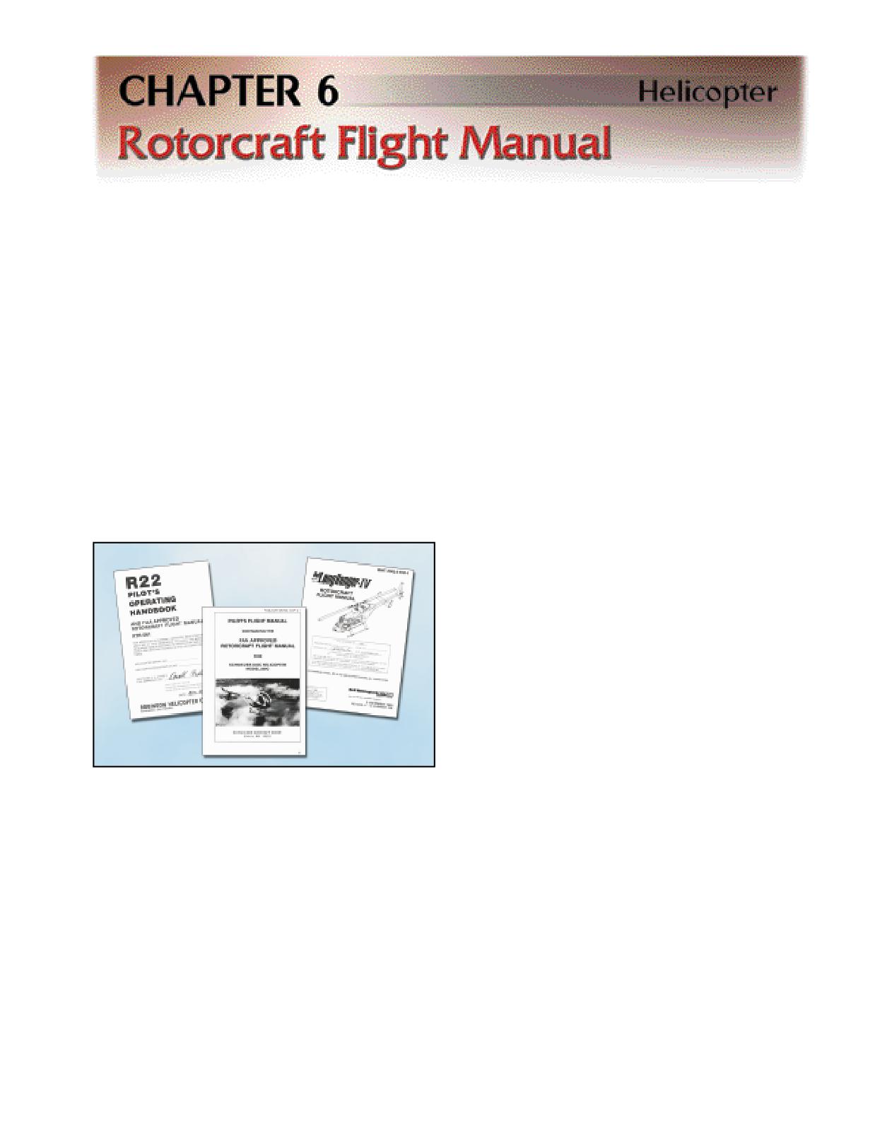
Title 14 of the Code of Federal Regulations (14 CFR)
ual is unique since it contains specific information
part 91 requires that pilots comply with the operating
about a particular aircraft, such as the equipment
limitations specified in approved rotorcraft flight man-
installed, and weight and balance information.
uals, markings, and placards. Originally, flight manuals
Therefore, manufacturers are required to include the
were often characterized by a lack of essential infor-
serial number and registration on the title page to iden-
mation and followed whatever format and content the
tify the aircraft to which the flight manual belongs. If a
manufacturer felt was appropriate. This changed with
flight manual does not indicate a specific aircraft regis-
the acceptance of the General Aviation Manufacturers
tration and serial number, it is limited to general study
Association’s (GAMA) Specification for Pilot’s
purposes only.
Operating Handbook, which established a standardized
format for all general aviation airplane and rotorcraft
Most manufacturers include a table of contents, which
flight manuals. The term “Pilot’s Operating Handbook
identifies the order of the entire manual by section num-
(POH)” is often used in place of “Rotorcraft Flight
ber and title. Usually, each section also contains its own
Manual (RFM).” However, if “Pilot’s Operating
table of contents. Page numbers reflect the section you
Handbook” is used as the main title instead of “Rotorcraft
are reading, 1-1, 2-1, 3-1, and so on. If the flight manual
Flight Manual,” a statement must be included on the title
is published in looseleaf form, each section is usually
page indicating that the document is the FAA-Approved
marked with a divider tab indicating the section number
Rotorcraft Flight Manual. [Figure 6-1]
or title, or both. The Emergency Procedures section may
have a red tab for quick identification and reference.
GENERAL INFORMATION
The General Information section provides the basic
descriptive information on the rotorcraft and the power-
plant. In some manuals there is a three-view drawing of
the rotorcraft that provides the dimensions of various
components, including the overall length and width, and
the diameter of the rotor systems. This is a good place to
quickly familiarize yourself with the aircraft.
You can find definitions, abbreviations, explanations of
symbology, and some of the terminology used in the
manual at the end of this section. At the option of the
manufacturer, metric and other conversion tables may
Figure 6-1. The Rotorcraft Flight Manual is a regulatory docu-
ment in terms of the maneuvers, procedures, and operating
also be included.
limitations described therein.
OPERATING LIMITATIONS
Besides the preliminary pages, an FAA-Approved
The Operating Limitations section contains only those
Rotorcraft Flight Manual may contain as many as ten sec-
limitations required by regulation or that are necessary
tions. These sections are: General Information; Operating
for the safe operation of the rotorcraft, powerplant, sys-
Limitations; Emergency Procedures; Normal Procedures;
tems, and equipment. It includes operating limitations,
Performance; Weight and Balance; Aircraft and Systems
instrument markings, color coding, and basic placards.
Description; Handling, Servicing, and Maintenance; and
Some of the areas included are: airspeed, altitude, rotor,
Supplements. Manufacturers have the option of including
and powerplant limitations, including fuel and oil
a tenth section on Safety and Operational Tips and an
requirements; weight and loading distribution; and
alphabetical index at the end of the handbook.
flight limitations.
PRELIMINARY PAGES
AIRSPEED LIMITATIONS
While rotorcraft flight manuals may appear similar for
Airspeed limitations are shown on the airspeed indica-
the same make and model of aircraft, each flight man-
tor by color coding and on placards or graphs in the
6-1
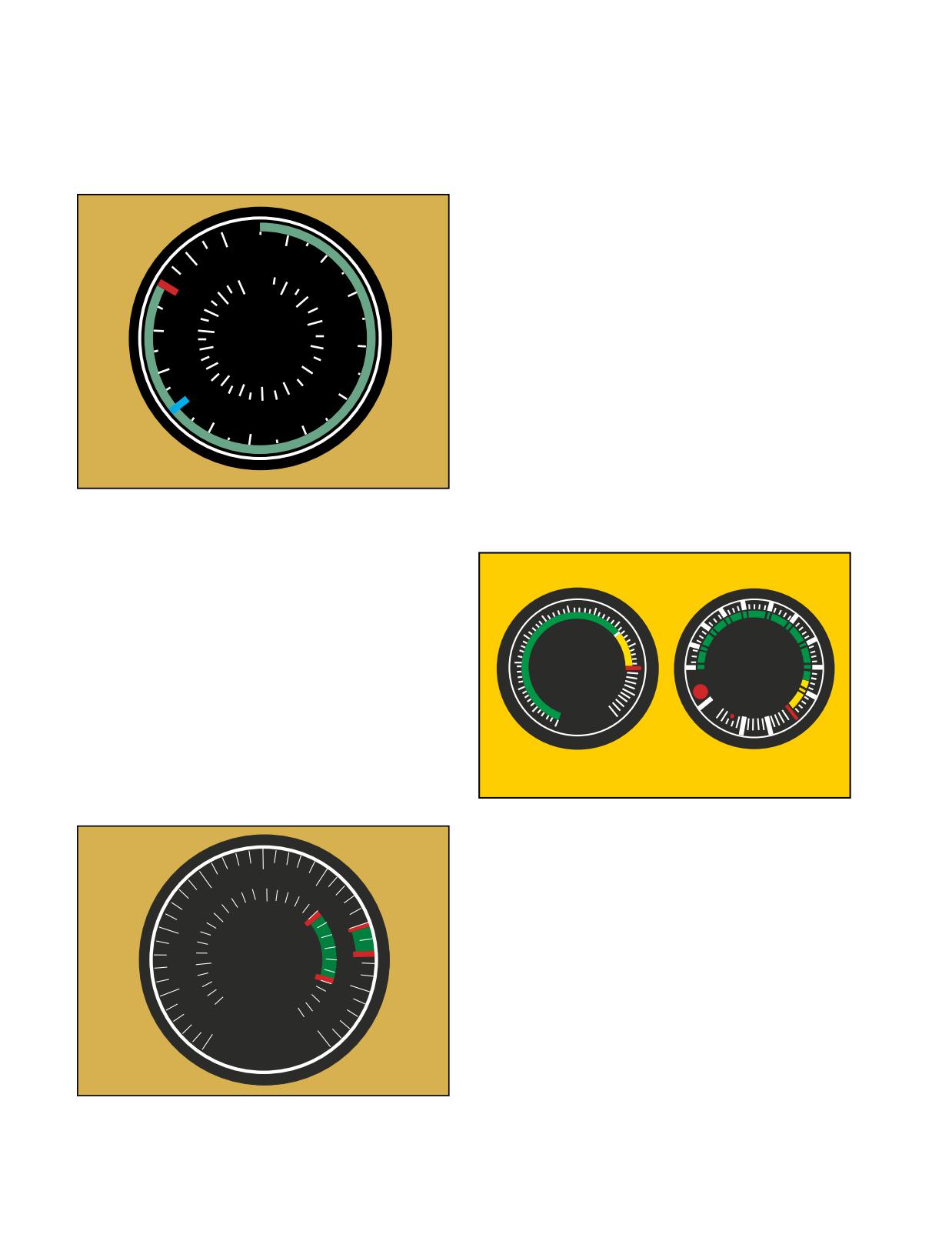
aircraft. A red line on the airspeed indicator shows the
There are two different rotor r.p.m. limitations: power-on
airspeed limit beyond which structural damage could
and power-off. Power-on limitations apply anytime the
occur. This is called the never exceed speed, or VNE.
engine is turning the rotor and is depicted by a fairly nar-
The normal operating speed range is depicted by a green
row green band. A yellow arc may be included to show a
arc. A blue line is sometimes added to show the maxi-
transition range, which means that operation within this
mum safe autorotation speed. [Figure 6-2]
range is limited. Power-off limitations apply anytime the
engine is not turning the rotor, such as when in an autoro-
tation. In this case, the green arc is wider than the power-
on arc, indicating a larger operating range.
150
20
POWERPLANT LIMITATIONS
The Powerplant Limitations area describes operating
limitations on the rotorcraft’s engine including such
17
40
4
items as r.p.m. range, power limitations, operating tem-
AIRSPEED
120
14
peratures, and fuel and oil requirements. Most turbine
MPH
6
12
X 10
engines and some reciprocating engines have a maxi-
8
mum power and a maximum continuous power rating.
100
60
The “maximum power” rating is the maximum power
KNOTS
the engine can generate and is usually limited by time.
80
The maximum power range is depicted by a yellow arc
on the engine power instruments, with a red line indi-
cating the maximum power that must not be exceeded.
“Maximum continuous power” is the maximum power
Figure 6-2. Typical airspeed indicator limitations and mark-
the engine can generate continually, and is depicted by
ings.
a green arc. [Figure 6-4]
ALTITUDE LIMITATIONS
If the rotorcraft has a maximum operating density alti-
tude, it is indicated in this section of the flight manual.
Sometimes the maximum altitude varies based on differ-
60 70
45
50
6
80
3
ent gross weights.
40
TURB
TORQUE
90
2
OUT
30
1
100
7
ROTOR LIMITATIONS
20
PERCENT
TEMP
110
10
°C X 100
Low rotor r.p.m. does not produce sufficient lift, and
120
8
0
9
high r.p.m. may cause structural damage, therefore
rotor r.p.m. limitations have minimum and maximum
values. A green arc depicts the normal operating range
with red lines showing the minimum and maximum
limits. [Figure 6-3]
Figure 6-4. Torque and turbine outlet temperature (TOT)
gauges are commonly used with turbine-powered aircraft.
20
l5
25
Like on a torque and turbine outlet temperature gauge,
3
the red line on a manifold pressure gauge indicates the
2
4
30
maximum amount of power. A yellow arc on the gauge
l0
warns of pressures approaching the limit of rated
l
5
power. A placard near the gauge lists the maximum
RPM
35
5
readings for specific conditions. [Figure 6-5]
100
ROTOR
40
WEIGHT AND LOADING DISTRIBUTION
The Weight and Loading Distribution area contains the
ENGINE
maximum certificated weights, as well as the center of
gravity (CG) range. The location of the reference datum
used in balance computations should also be included in
Figure 6-3. Markings on a typical dual-needle tachometer in a
this section. Weight and balance computations are not
reciprocating-engine helicopter. The outer band shows the
limits of the superimposed needles when the engine is turn-
provided here, but rather in the Weight and Balance
ing the rotor. The inner band indicates the power-off limits.
Section of the FAA-Approved Rotocraft Flight Manual.
6-2
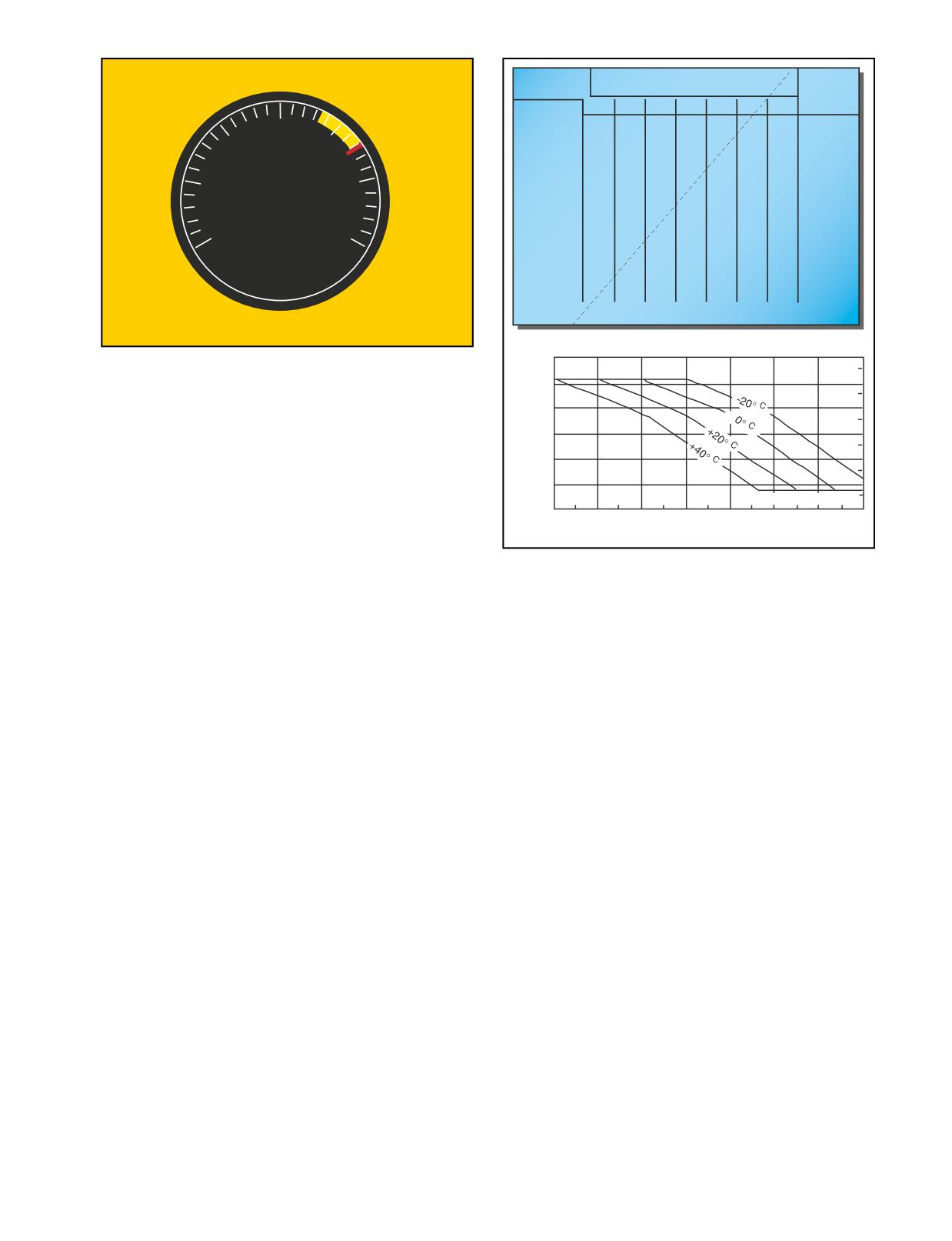
Press Alt.
VNE - MPH IAS
1,000 FT
GROSS
F OAT
8
4
6
8
10
12
14
WEIGHT
0
109
109
105
84
61
--
--
MORE
20
l5
20
109
109
94
72
49
--
--
THAN
25
1,700
40
09
103
81
59
--
--
--
MANIFOLD
LBS
60
109
91
70
48
--
--
--
PRESSURE
80
109
80
59
--
--
--
--
l0
30
100
109
70
48
--
--
--
--
0
109
109
109
109
98
77
58
1,700
INCHES
20
109
109
109
109
85
67
48
LBS
5
OF MERCURY
35
40
109
109
109
96
75
57
--
OR
60
109
109
108
84
66
48
--
LESS
80
109
109
95
74
57
--
--
100
109
108
84
66
48
--
--
MAXIMUM VNE DOORS OFF - 102 MPH IAS
NEVER EXCEED SPEED
110
Figure 6-5. A manifold pressure gauge is commonly used
with piston-powered aircraft.
100
VNE
90
FLIGHT LIMITATIONS
80
This area lists any maneuvers which are prohibited,
KIAS
70
such as acrobatic flight or flight into known icing con-
ditions. If the rotorcraft can only be flown in VFR
60
MAX ALT.
conditions, it will be noted in this area. Also included
50
0
2
4
6
8
10
12
14
are the minimum crew requirements, and the pilot seat
Pressure Alt. 1,000 Feet
location, if applicable, where solo flights must be con-
ducted.
Figure 6-6. Various VNE placards.
PLACARDS
All rotorcraft generally have one or more placards dis-
Manufacturers also are encouraged to include an optional
played that have a direct and important bearing on the
area titled “Abnormal Procedures,” which describes rec-
safe operation of the rotorcraft. These placards are
ommended procedures for handling malfunctions that are
located in a conspicuous place within the cabin and
not considered to be emergencies. This information
normally appear in the Limitations Section. Since VNE
would most likely be found in larger helicopters.
changes with altitude, this placard can be found in all
helicopters. [Figure 6-6]
NORMAL PROCEDURES
The Normal Procedures is the section you will proba-
EMERGENCY PROCEDURES
bly use the most. It usually begins with a listing of the
Concise checklists describing the recommended proce-
airspeeds, which may enhance the safety of normal
dures and airspeeds for coping with various types of
operations. It is a good idea to memorize the airspeeds
emergencies or critical situations can be found in this
that are used for normal flight operations. The next part
of the section includes several checklists, which take
section. Some of the emergencies covered include:
you through the preflight inspection, before starting
engine failure in a hover and at altitude, tail rotor fail-
procedure, how to start the engine, rotor engagement,
ures, fires, and systems failures. The procedures for
ground checks, takeoff, approach, landing, and shut-
restarting an engine and for ditching in the water might
down. Some manufacturers also include the procedures
also be included.
for practice autorotations. To avoid skipping an impor-
tant step, you should always use a checklist when one is
Manufacturers may first show the emergencies check-
available. (More information on maneuvers can be
lists in an abbreviated form with the order of items
found in Chapter 9-Basic Maneuvers, Chapter 10-
reflecting the sequence of action. This is followed by
Advanced Maneuvers, and Chapter 20-Gyroplane
amplified checklists providing additional information
Flight Operations.)
to help you understand the procedure. To be prepared
for an abnormal or emergency situation, memorize the
first steps of each checklist, if not all the steps. If time
PERFORMANCE
permits, you can then refer to the checklist to make sure
The Performance Section contains all the information
all items have been covered. (For more information on
required by the regulations, and any additional per-
emergencies, refer to Chapter 11-Helicopter Emergencies
formance information the manufacturer feels may
and Chapter 21-Gyroplane Emergencies.)
enhance your ability to safely operate the rotorcraft.
6-3
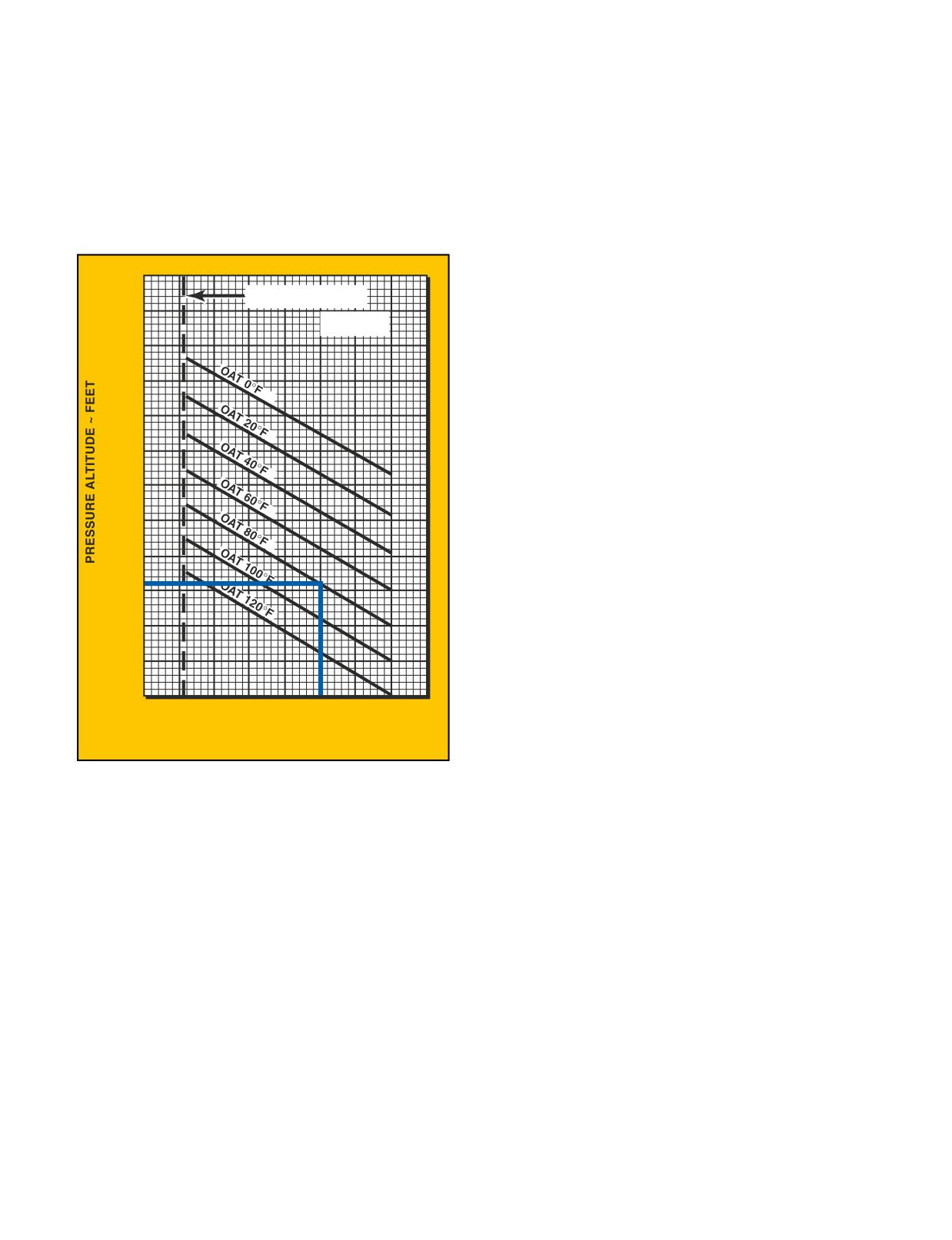
These charts, graphs, and tables vary in style but all
ers should describe the systems in a manner that is
contain the same basic information. Some examples
understandable to most pilots. For larger, more com-
of the performance information that can be found in
plex rotorcraft, the manufacturer may assume a higher
most flight manuals include a calibrated versus indi-
degree of knowledge. (For more information on rotor-
cated airspeed conversion graph, hovering ceiling
craft systems, refer to Chapter 5-Helicopter Systems
versus gross weight charts, and a height-velocity dia-
and Chapter 18-Gyroplane Systems.)
gram. [Figure 6-7] For information on how to use the
charts, graphs, and tables, refer to Chapter 8-
HANDLING, SERVICING, AND
Performance.
MAINTENANCE
The Handling, Servicing, and Maintenance section
describes the maintenance and inspections recom-
12,000
mended by the manufacturer, as well as those required
8,000 FT.
DENSITY ALTITUDE
by the regulations, and Airworthiness Directive (AD)
MIXTURE
compliance procedures. There are also suggestions on
FULL RICH
how the pilot/operator can ensure that the work is done
10,000
properly.
This section also describes preventative maintenance
that may be accomplished by certificated pilots, as
8,000
well as the manufacturer’s recommended ground han-
dling procedures, including considerations for
hangaring, tie down, and general storage procedures
6,000
for the rotorcraft.
SUPPLEMENTS
The Supplements Section describes pertinent informa-
4,000
tion necessary to operate optional equipment installed on
the rotorcraft that would not be installed on a standard
aircraft. Some of this information may be supplied by the
2,000
aircraft manufacturer, or by the maker of the optional
equipment. The information is then inserted into the
flight manual at the time the equipment is installed.
0
SAFETY AND OPERATIONAL TIPS
1,400
1,500
1,600
1,700
1,800
The Safety and Operational Tips is an optional section
GROSS WEIGHT ~ LBS
that contains a review of information that could
enhance the safety of the operation. Some examples of
the information that might be covered include: physio-
Figure 6-7. One of the performance charts in the Performance
Section is the “In Ground Effect Hover Ceiling versus Gross
logical factors, general weather information, fuel con-
Weight” chart. This chart allows you to determine how much
servation procedures, external load warnings, low rotor
weight you can carry and still operate at a specific pressure
altitude, or if you are carrying a specific weight, what is your
r.p.m. considerations, and recommendations that if not
altitude limitation.
adhered to could lead to an emergency.
WEIGHT AND BALANCE
The Weight and Balance section should contain all the
Airworthiness Directive (AD)-A
information required by the FAA that is necessary to
regulatory notice that is sent out
calculate weight and balance. To help you correctly
by the FAA to the registered own-
compute the proper data, most manufacturers include
ers of aircraft informing them of
the discovery of a condition that
sample problems. (Weight and balance is further dis-
keeps their aircraft from continu-
cussed in Chapter 7-Weight and Balance.)
ing to meet its conditions for air-
worthiness. Airworthiness
Directives must be complied with
AIRCRAFT AND SYSTEMS
within the required time limit, and
the fact of compliance, the date of
DESCRIPTION
compliance, and the method of
compliance must be recorded in
The Aircraft and Systems Description section is an
the aircraft maintenance records.
excellent place to study and familiarize yourself with
all the systems found on your aircraft. The manufactur-
6-4
It is vital to comply with weight and balance limits
WEIGHT LIMITATIONS
established for helicopters. Operating above the maxi-
Weight limitations are necessary to guarantee the struc-
mum weight limitation compromises the structural
tural integrity of the helicopter, as well as enabling you
integrity of the helicopter and adversely affects per-
to predict helicopter performance accurately. Although
formance. Balance is also critical because on some
aircraft manufacturers build in safety factors, you
fully loaded helicopters, center of gravity deviations as
should never intentionally exceed the load limits for
small as three inches can dramatically change a heli-
which a helicopter is certificated. Operating above a
copter’s handling characteristics. Taking off in a heli-
maximum weight could result in structural deformation
copter that is not within the weight and balance
or failure during flight if you encounter excessive load
limitations is unsafe.
factors, strong wind gusts, or turbulence. Operating
below a minimum weight could adversely affect the
handling characteristics of the helicopter. During sin-
WEIGHT
gle-pilot operations in some helicopters, you may have
When determining if your helicopter is within the
to use a large amount of forward cyclic in order to
weight limits, you must consider the weight of the basic
maintain a hover. By adding ballast to the helicopter,
helicopter, crew, passengers, cargo, and fuel. Although
the cyclic will be closer to the center, which gives you
the effective weight (load factor) varies during maneu-
a greater range of control motion in every direction.
vering flight, this chapter primarily considers the
Additional weight also improves autorotational charac-
weight of the loaded helicopter while at rest.
teristics since the autorotational descent can be estab-
The following terms are used when computing a heli-
lished sooner. In addition, operating below minimum
copter’s weight.
weight could prevent you from achieving the desirable
rotor r.p.m. during autorotations.
BASIC EMPTY WEIGHT-The starting point for
weight computations is the basic empty weight, which
Although a helicopter is certificated for a specified
is the weight of the standard helicopter, optional
maximum gross weight, it is not safe to take off with
equipment, unusable fuel, and full operating fluids
this load under all conditions. Anything that adversely
including full engine oil. Some helicopters might use
affects takeoff, climb, hovering, and landing perform-
the term “licensed empty weight,” which is nearly the
ance may require off-loading of fuel, passengers, or
same as basic empty weight, except that it does not
baggage to some weight less than the published maxi-
include full engine oil, just undrainable oil. If you fly a
mum. Factors which can affect performance include
helicopter that lists a licensed empty weight, be sure to
high altitude, high temperature, and high humidity con-
add the weight of the oil to your computations.
ditions, which result in a high density altitude.
USEFUL LOAD-The difference between the gross
DETERMINING EMPTY WEIGHT
weight and the basic empty weight is referred to as
A helicopter’s weight and balance records contain
useful load. It includes the flight crew, usable fuel,
essential data, including a complete list of all installed
drainable oil, if applicable, and payload.
optional equipment. Use these records to determine the
weight and balance condition of the empty helicopter.
PAYLOAD-The weight of the passengers, cargo, and
baggage.
When a helicopter is delivered from the factory, the basic
empty weight, empty weight center of gravity (CG), and
GROSS WEIGHT-The sum of the basic empty weight
useful load are recorded on a weight and balance data
and useful load.
sheet included in the FAA-Approved Rotocraft Flight
MAXIMUM GROSS WEIGHT- The maximum
Manual. The basic empty weight can vary even in the
weight of the helicopter. Most helicopters have an inter-
same model of helicopter because of differences in
nal maximum gross weight, which refers to the weight
installed equipment. If the owner or operator of a heli-
within the helicopter structure and an external maximum
copter has equipment removed, replaced, or additional
gross weight, which refers to the weight of the helicopter
equipment installed, these changes must be reflected in
with an external load.
the weight and balance records. In addition, major
7-1
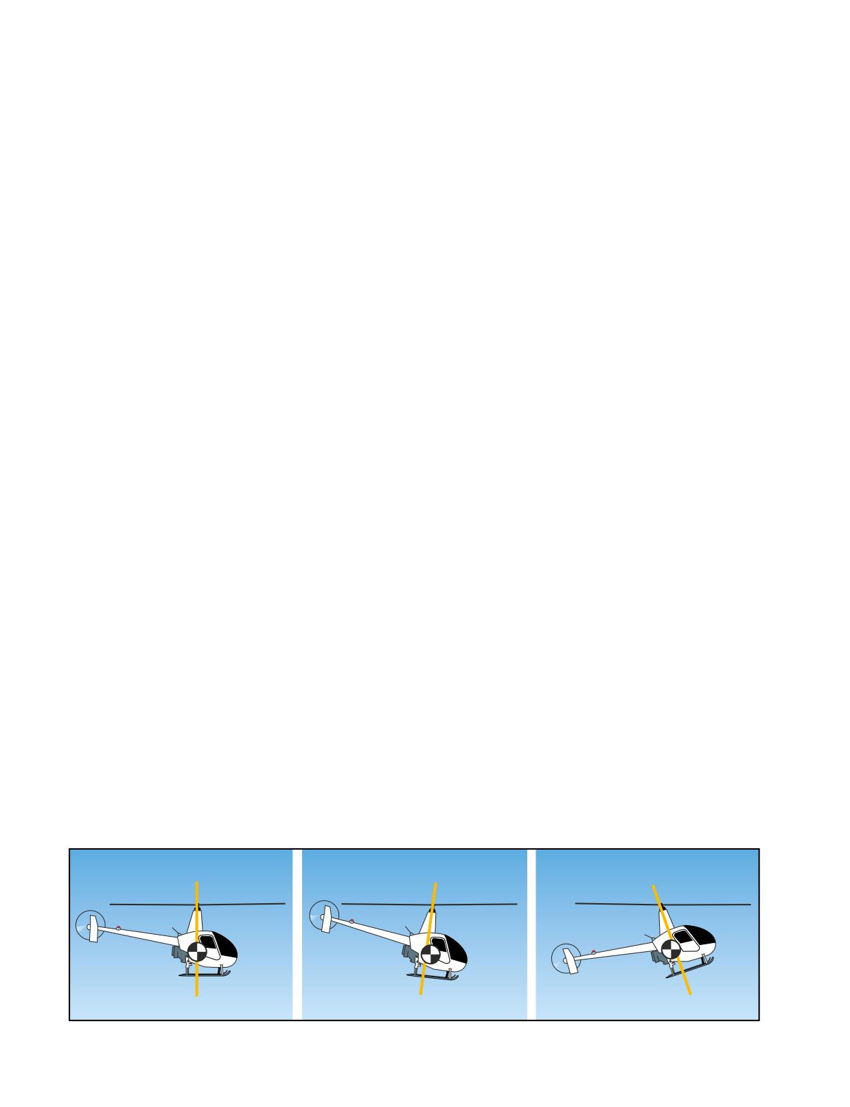
repairs or alterations must be recorded by a certified
CG FORWARD OF FORWARD LIMIT
mechanic. When the revised weight and moment are
A forward CG may occur when a heavy pilot and pas-
recorded on a new form, the old record is marked with
senger take off without baggage or proper ballast
the word “superseded” and dated with the effective
located aft of the rotor mast. This situation becomes
date of the new record. This makes it easy to determine
worse if the fuel tanks are located aft of the rotor mast
which weight and balance form is the latest version.
because as fuel burns the weight located aft of the rotor
You must use the latest weight and balance data for
mast becomes less.
computing all loading problems.
You can recognize this condition when coming to a
BALANCE
hover following a vertical takeoff. The helicopter will
Helicopter performance is not only affected by gross
have a nose-low attitude, and you will need excessive
weight, but also by the position of that weight. It is
rearward displacement of the cyclic control to maintain
essential to load the aircraft within the allowable center-
a hover in a no-wind condition. You should not continue
of-gravity range specified in the rotorcraft flight man-
flight in this condition, since you could rapidly run out
ual’s weight and balance limitations.
of rearward cyclic control as you consume fuel. You also
may find it impossible to decelerate sufficiently to bring
CENTER OF GRAVITY (CG)
the helicopter to a stop. In the event of engine failure and
The center of gravity is defined as the theoretical point
the resulting autorotation, you may not have enough
where all of the aircraft’s weight is considered to be
cyclic control to flare properly for the landing.
concentrated. If a helicopter was suspended by a cable
attached to the center-of-gravity point, it would balance
A forward CG will not be as obvious when hovering into
like a teeter-totter. For helicopters with a single main
a strong wind, since less rearward cyclic displacement is
rotor, the CG is usually close to the main rotor mast.
required than when hovering with no wind. When deter-
mining whether a critical balance condition exists, it is
Improper balance of a helicopter’s load can result in
essential to consider the wind velocity and its relation to
serious control problems. The allowable range in which
the rearward displacement of the cyclic control.
the CG may fall is called the “CG range.” The exact
CG location and range are specified in the rotorcraft
CG AFT OF AFT LIMIT
flight manual for each helicopter. In addition to making
Without proper ballast in the cockpit, exceeding the aft
a helicopter difficult to control, an out-of-balance load-
CG may occur when:
ing condition also decreases maneuverability since
cyclic control is less effective in the direction opposite
•
A lightweight pilot takes off solo with a full load
to the CG location.
of fuel located aft of the rotor mast.
Ideally, you should try to perfectly balance a helicopter
•
A lightweight pilot takes off with maximum bag-
so that the fuselage remains horizontal in hovering
gage allowed in a baggage compartment located
flight, with no cyclic pitch control needed except for
aft of the rotor mast.
wind correction. Since the fuselage acts as a pendulum
suspended from the rotor, changing the center of grav-
•
A lightweight pilot takes off with a combination
ity changes the angle at which the aircraft hangs from
of baggage and substantial fuel where both are aft
the rotor. When the center of gravity is directly under
of the rotor mast.
the rotor mast, the helicopter hangs horizontal; if the
CG is too far forward of the mast, the helicopter hangs
You can recognize the aft CG condition when coming
with its nose tilted down; if the CG is too far aft of the
to a hover following a vertical takeoff. The helicopter
mast, the nose tilts up. [Figure 7-1]
will have a tail-low attitude, and you will need exces-
CG Directly Under The Rotor Mast
Forward CG
Aft CG
Figure 7-1. The location of the center of gravity strongly influences how the helicopter handles.
7-2
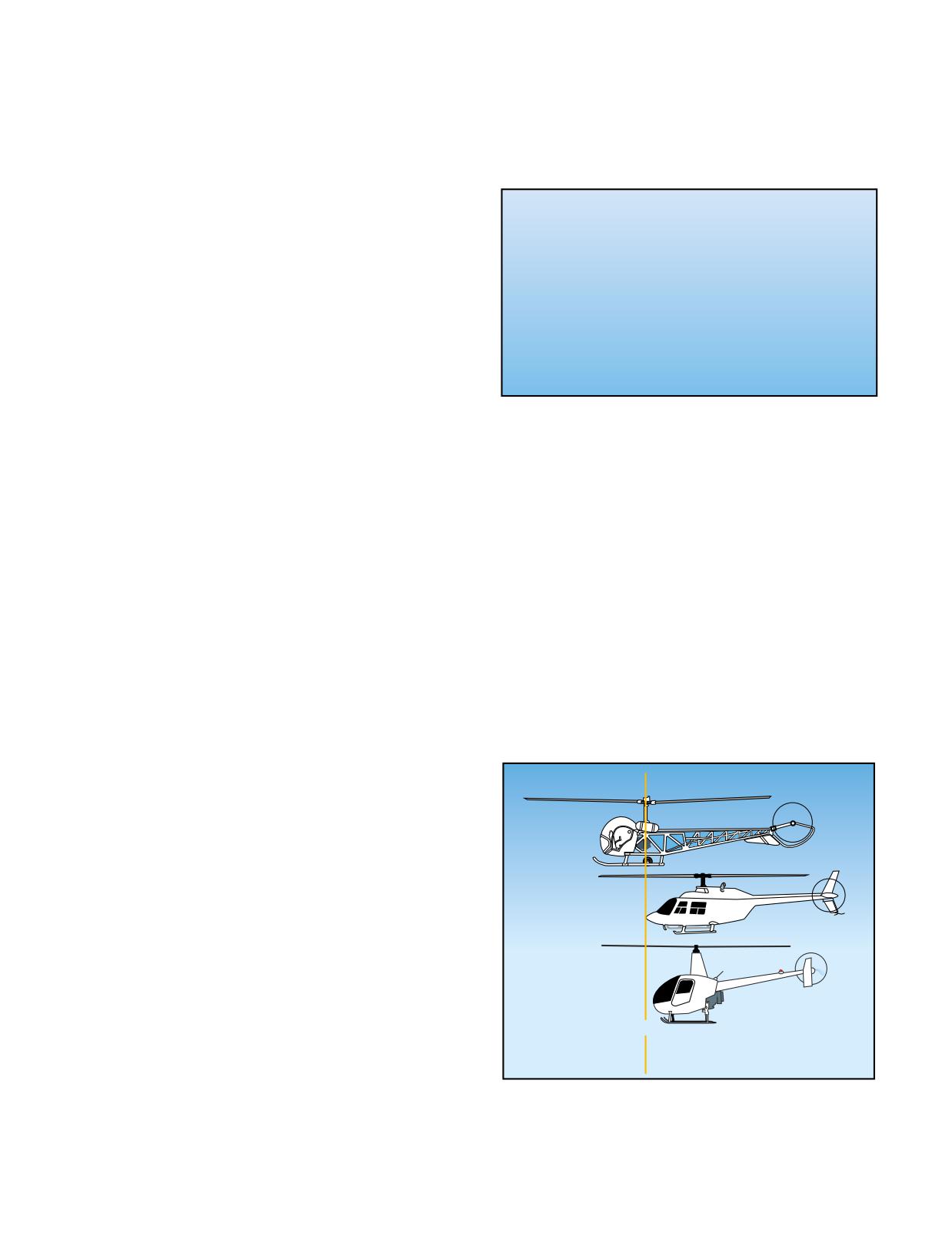
sive forward displacement of cyclic control to main-
and add a few pounds to cover the additional weight of
tain a hover in a no-wind condition. If there is a wind,
clothing, especially during the winter months. The bag-
you need even greater forward cyclic.
gage weight should be determined by the use of a scale, if
practical. If a scale is not available, be conservative and
If flight is continued in this condition, you may find it
overestimate the weight. Figure 7-2 indicates the stan-
impossible to fly in the upper allowable airspeed range
dard weights for specific operating fluids.
due to inadequate forward cyclic authority to maintain a
nose-low attitude. In addition, with an extreme aft CG,
Aviation Gasoline (AVGAS)
6 lbs. / gal.
gusty or rough air could accelerate the helicopter to a
speed faster than that produced with full forward cyclic
Jet Fuel (JP-4)
6.5 lbs. / gal.
control. In this case, dissymmetry of lift and blade flap-
Jet Fuel (JP-5)
6.8 lbs. / gal.
ping could cause the rotor disc to tilt aft. With full for-
Reciprocating Engine Oil
7.5 lbs. / gal.*
ward cyclic control already applied, you might not be
Turbine Engine Oil . . Varies between 7.5 and 8.5 lbs. / gal.*
able to lower the rotor disc, resulting in possible loss of
Water
8.35 lbs. / gal.
control, or the rotor blades striking the tailboom.
* Oil weight is given in pounds per gallon while oil capacity
LATERAL BALANCE
is usually given in quarts; therefore, you must convert the
amount of oil to gallons before calculating its weight.
For most helicopters, it is usually not necessary to
determine the lateral CG for normal flight instruction
Figure 7-2. When making weight and balance computations,
and passenger flights. This is because helicopter cab-
always use actual weights if they are available, especially if
ins are relatively narrow and most optional equip-
the helicopter is loaded near the weight and balance limits.
ment is located near the center line. However, some
helicopter manuals specify the seat from which you
The following terms are used when computing a heli-
must conduct solo flight. In addition, if there is an
copter’s balance.
unusual situation, such as a heavy pilot and a full
load of fuel on one side of the helicopter, which could
REFERENCE DATUM-Balance is determined by the
affect the lateral CG, its position should be checked
location of the CG, which is usually described as a
against the CG envelope. If carrying external loads in
given number of inches from the reference datum. The
a position that requires large lateral cyclic control
horizontal reference datum is an imaginary vertical
displacement to maintain level flight, fore and aft
plane or point, arbitrarily fixed somewhere along the
cyclic effectiveness could be dramatically limited.
longitudinal axis of the helicopter, from which all hori-
zontal distances are measured for weight and balance
WEIGHT AND BALANCE
purposes. There is no fixed rule for its location. It may
CALCULATIONS
be located at the rotor mast, the nose of the helicopter,
When determining whether your helicopter is properly
or even at a point in space ahead of the helicopter.
loaded, you must answer two questions:
[Figure 7-3]
1.
Is the gross weight less than or equal to the max-
imum allowable gross weight?
2.
Is the center of gravity within the allowable CG
range, and will it stay within the allowable range
as fuel is burned off?
To answer the first question, just add the weight of the
items comprising the useful load (pilot, passengers,
fuel, oil, if applicable, cargo, and baggage) to the basic
empty weight of the helicopter. Check that the total weight
does not exceed the maximum allowable gross weight.
To answer the second question, you need to use CG or
moment information from loading charts, tables, or graphs
Datum
in the rotorcraft flight manual. Then using one of the
-
+
methods described below, calculate the loaded moment
and/or loaded CG and verify that it falls within the allow-
able CG range shown in the rotorcraft flight manual.
Figure 7-3. While the horizontal reference datum can be any-
where the manufacturer chooses, most small training heli-
It is important to note that any weight and balance com-
copters have the horizontal reference datum 100 inches
putation is only as accurate as the information provided.
forward of the main rotor shaft centerline. This is to keep all
Therefore, you should ask passengers what they weigh
the computed values positive.
7-3
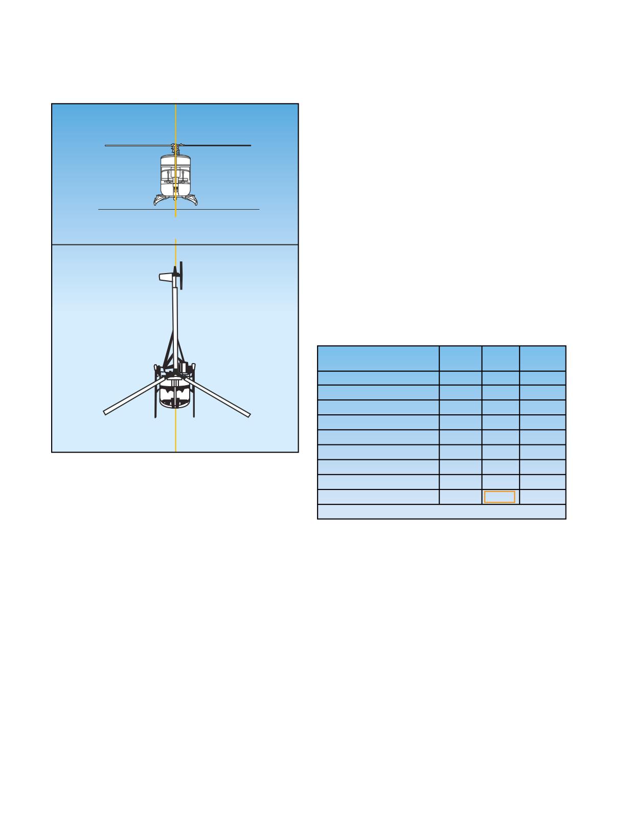
The lateral reference datum, is usually located at the
CENTER OF GRAVITY COMPUTATION-By totaling the
center of the helicopter. The location of the reference
weights and moments of all components and objects car-
datums is established by the manufacturer and is
ried, you can determine the point where a loaded heli-
defined in the rotorcraft flight manual. [Figure 7-4]
copter would balance. This point is known as the center
of gravity.
Front View
WEIGHT AND BALANCE METHODS
+
-
Since weight and balance is so critical to the safe oper-
ation of a helicopter, it is important to know how to
check this condition for each loading arrangement.
Most helicopter manufacturers use one of two meth-
ods, or a combination of the methods, to check weight
and balance conditions.
Lateral
COMPUTATIONAL METHOD
Datum
With the computational method, you use simple math-
ematics to solve weight and balance problems. The first
step is to look up the basic empty weight and total
Top View
moment for the particular helicopter you fly. If the cen-
ter of gravity is given, it should also be noted. The
empty weight CG can be considered the arm of the
empty helicopter. This should be the first item recorded
on the weight and balance form. [Figure 7-5]
Weight
Arm
Moment
(pounds)
(inches)
(lb/inches)
Basic Empty Weight
1,700
116.5
198,050
Oil
12
179.0
2,148
Pilot
190
65.0
12,350
Forward Passenger
170
65.0
11,050
+
-
Passengers Aft
510
104
53,040
Baggage
40
148
5,920
Figure 7-4. The lateral reference datum is located longitudi-
Fuel
553
120
66,360
nally through the center of the helicopter; therefore, there are
Total
3,175
348,918
positive and negative values.
CG
109.9
Max Gross Weight = 3,200 lbs. CG Range 106.0 - 114.2 in.
Figure 7-5. In this example, the helicopter’s weight of 1,700
ARM-The horizontal distance from the datum to any
pounds is recorded in the first column, its CG or arm of 116.5
component of the helicopter or to any object located
inches in the second, and its moment of 198,050 pound-
within the helicopter is called the arm. Another term
inches in the last. Notice that the weight of the helicopter,
multiplied by its CG, equals its moment.
that can be used interchangeably with arm is station.
If the component or object is located to the rear of the
datum, it is measured as a positive number and usu-
ally is referred to as inches aft of the datum.
Next, the weights of the oil, if required, pilot, passen-
Conversely, if the component or object is located for-
gers, baggage, and fuel are recorded. Use care in
ward of the datum, it is indicated as a negative num-
recording the weight of each passenger and baggage.
ber and is usually referred to as inches forward of the
Recording each weight in its proper location is
datum.
extremely important to the accurate calculation of a
CG. Once you have recorded all of the weights, add
MOMENT-If the weight of an object is multiplied by
them together to determine the total weight of the
its arm, the result is known as its moment. You may
loaded helicopter.
think of moment as a force that results from an object’s
weight acting at a distance. Moment is also referred to
Now, check to see that the total weight does not exceed
as the tendency of an object to rotate or pivot about a
the maximum allowable weight under existing condi-
point. The farther an object is from a pivotal point, the
tions. In this case, the total weight of the helicopter is
greater its force.
under the maximum gross weight of 3,200 pounds.
7-4
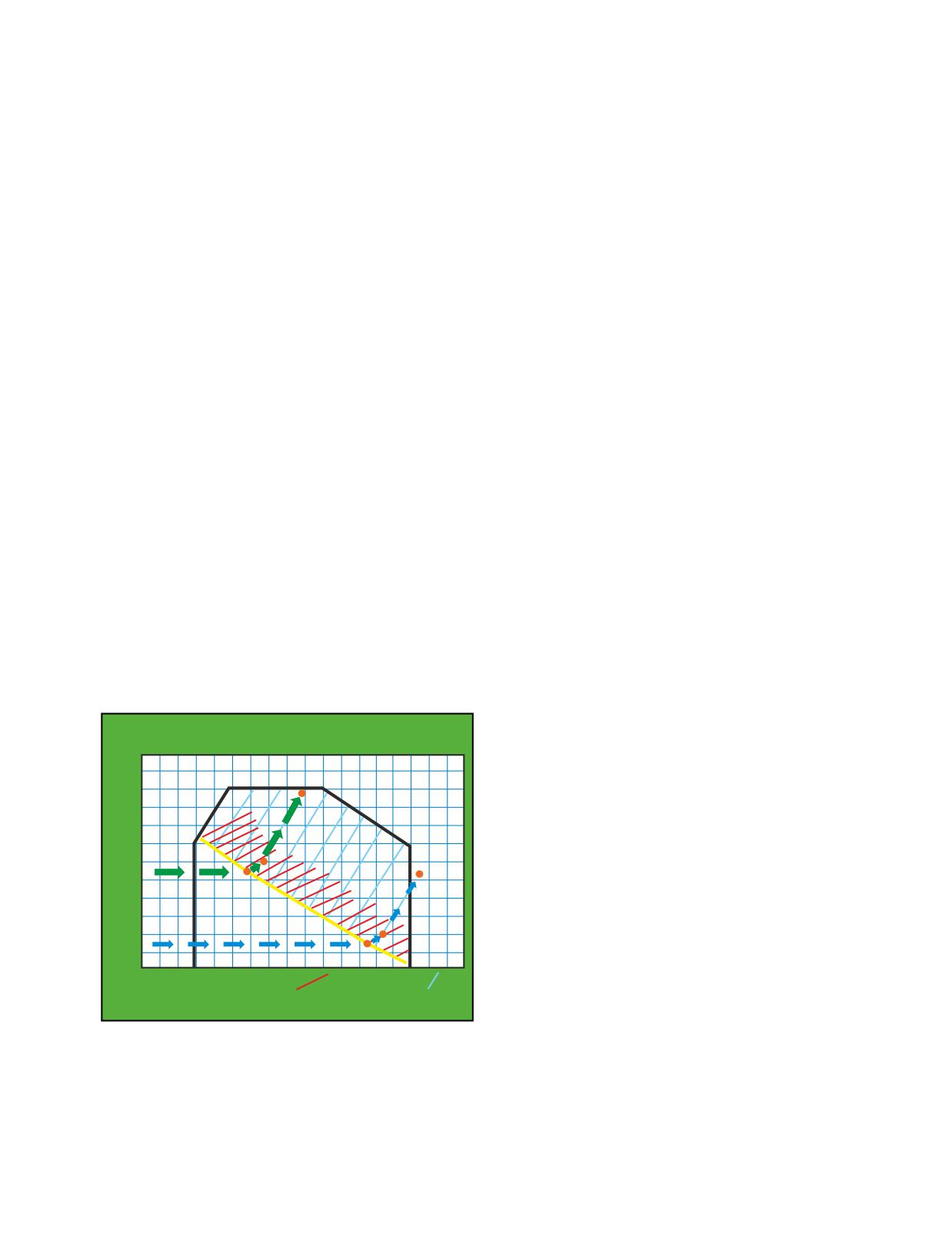
Once you are satisfied that the total weight is within
ITEM
POUNDS
prescribed limits, multiply each individual weight by
Basic empty weight
1,040
its associated arm to determine its moment. Then, add
Pilot
135
the moments together to arrive at the total moment for
Passenger
200
the helicopter. Your final computation is to find the
Subtotal
1,375 (point A)
center of gravity of the loaded helicopter by dividing
Baggage compartment load
25
the total moment by the total weight.
Subtotal
1,400 (point B)
Fuel load (30 gallons)
180
After determining the helicopter’s weight and center
Total weight
1,580 (point C)
of gravity location, you need to determine if the CG
is within acceptable limits. In this example, the
1.
Follow the green arrows in figure 7-6. Enter the
allowable range is between 106.0 inches and 114.2
graph on the left side at 1,375 lb., the subtotal of
inches. Therefore, the CG location is within the
the empty weight and the passenger weight.
acceptable range. If the CG falls outside the accept-
Move right to the yellow line. (point A)
able limits, you will have to adjust the loading of the
helicopter.
2.
Move up and to the right, parallel to the baggage
compartment loading lines to 1,400 lb. (Point B)
LOADING CHART METHOD
You can determine if a helicopter is within weight and
3.
Continue up and to the right, this time parallel to
CG limits using a loading chart similar to the one in
the fuel loading lines, to the total weight of 1,580
figure 7-6. To use this chart, first subtotal the empty
lb. (Point C).
weight, pilot, and passengers. This is the weight at
which you enter the chart on the left. The next step is to
Point C is within allowable weight and CG limits.
follow the upsloping lines for baggage and then for fuel
to arrive at your final weight and CG. Any value on or
SAMPLE PROBLEM 2
inside the envelope is within the range.
Assume that the pilot in sample problem 1 discharges
the passenger after using only 20 pounds of fuel.
SAMPLE PROBLEM 1
ITEM
POUNDS
Determine if the gross weight and center of gravity are
Basic empty weight
1,040
within allowable limits under the following loading
Pilot
135
conditions for a helicopter based on the loading chart
Subtotal
1,175 (point D)
in figure 7-6.
Baggage compartment load
25
Subtotal
1,200 (point E)
Fuel load
160
Total weight
1,360 (point F)
104
105
106
107
108
109
Follow the blue arrows in figure 7-6, starting at 1,175
1,600
C
lb. on the left side of the graph, then to point D, E, and
F. Although the total weight of the helicopter is well
1,500
below the maximum allowable gross weight, point F
falls outside the aft allowable CG limit.
1,400
F
A
B
As you can see, it is important to reevaluate the balance
1,300
in a helicopter whenever you change the loading. Unlike
E
most airplanes, where discharging a passenger is
1,200
unlikely to adversely affect the CG, off-loading a pas-
D
1,100
senger from a helicopter could make the aircraft unsafe
Baggage Compartment
Fuel Loading
Loading Lines
Lines
to fly. Another difference between helicopter and air-
plane loading is that most small airplanes carry fuel in
the wings very near the center of gravity. Burning off
Figure 7-6. Loading chart illustrating the solution to sample
fuel has little effect on the loaded CG. However, heli-
problems 1 and 2.
copter fuel tanks are often significantly behind the center
of gravity. Consuming fuel from a tank aft of the rotor
mast causes the loaded helicopter CG to move forward.
To use the loading chart for the helicopter in this exam-
As standard practice, you should compute the weight
ple, you must add up the items in a certain order. The
and balance with zero fuel to verify that your helicopter
maximum allowable gross weight is 1,600 pounds.
remains within the acceptable limits as fuel is used.
7-5
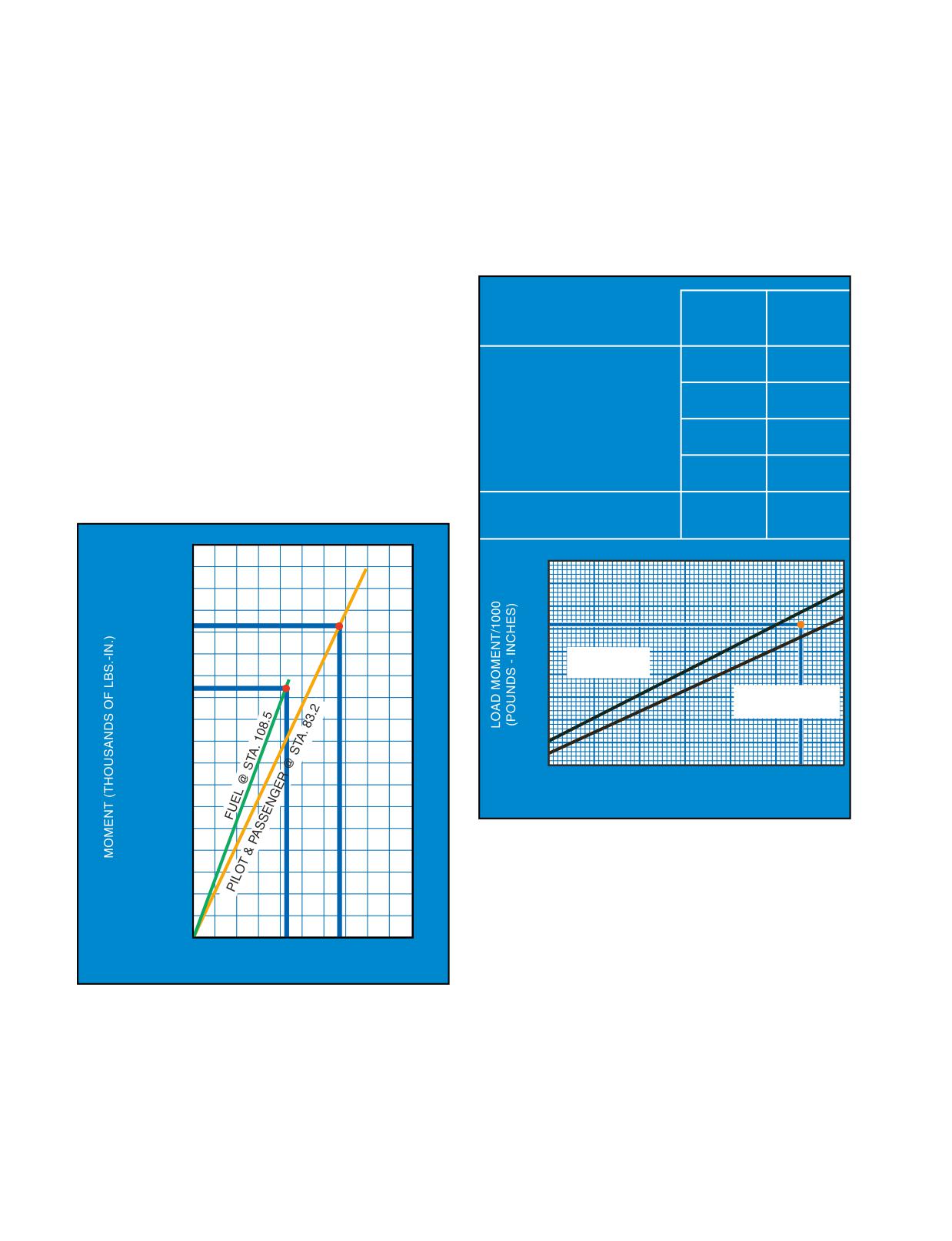
SAMPLE PROBLEM 3
@STA. 83.2.” Go left and read the pilot/passenger
The loading chart used in the sample problems 1 and 2
moment (28.3 thousand lb.-inches).
is designed to graphically calculate the loaded center of
gravity and show whether it is within limits, all on a
Reduction factors are often used to reduce the size of
single chart. Another type of loading chart calculates
large numbers to manageable levels. In figure 7-7, the
moments for each station. You must then add up these
scale on the loading graph gives you moments in thou-
moments and consult another graph to determine
sands of pound-inches. In most cases, when using this
whether the total is within limits. Although this method
type of chart, you need not be concerned with reduc-
has more steps, the charts are sometimes easier to use.
tion factors because the CG/moment envelope chart
normally uses the same reduction factor. [Figure 7-8]
To begin, record the basic empty weight of the helicop-
ter, along with its total moment. Remember to use the
actual weight and moment of the helicopter you are fly-
Weight
Moment
(lbs.)
(lb.-ins.
ing. Next, record the weights of the pilot, passengers,
/1,000)
fuel, and baggage on a weight and balance worksheet.
Then, determine the total weight of the helicopter.
1. Basic Empty Weight
1,102
110.8
Once you have determined the weight to be within pre-
scribed limits, compute the moment for each weight
2. Pilot and Front Passenger
340
28.3
and for the loaded helicopter. Do this with a loading
3. Fuel
211
22.9
graph provided by the manufacturer. Use figure 7-7 to
determine the moments for a pilot and passenger
5. Baggage
weighing 340 pounds and for 211 pounds of fuel.
TOTALS
1,653
162.0
36
190
180
32
170
28
160
150
Aft CG Limit
24
140
Station 101.0
130
Forward CG Limit
Station 95.0
20
120
110
16
100
1,100
1,200
1,300
1,400
1,500
1,600
1,700
12
LOADED WEIGHT (POUND)
Figure 7-8. CG/Moment Chart.
8
4
After recording the basic empty weight and moment of
the helicopter, and the weight and moment for each
item, total and record all weights and moments. Next,
0
100
200
300
400
500
plot the calculated takeoff weight and moment on the
LOAD WEIGHT (LBS)
sample moment envelope graph. Based on a weight of
1,653 pounds and a moment/1,000 of 162 pound-inches,
Figure 7-7. Moments for fuel, pilot, and passenger.
the helicopter is within the prescribed CG limits.
Start at the bottom scale labeled LOAD WEIGHT.
COMBINATION METHOD
Draw a line from 211 pounds up to the line labeled
The combination method usually uses the computa-
“FUEL @ STA108.5.” Draw your line to the left to
tion method to determine the moments and center of
intersect the MOMENT scale and read the fuel moment
gravity. Then, these figures are plotted on a graph to
(22.9 thousand lb.-inches). Do the same for the pilot/pas-
determine if they intersect within the acceptable enve-
senger moment. Draw a line from a weight of 340
lope. Figure 7-9 illustrates that with a total weight of
pounds up to the line labeled “PILOT & PASSENGER
2,399 pounds and a total moment of 225,022 pound-
7-6
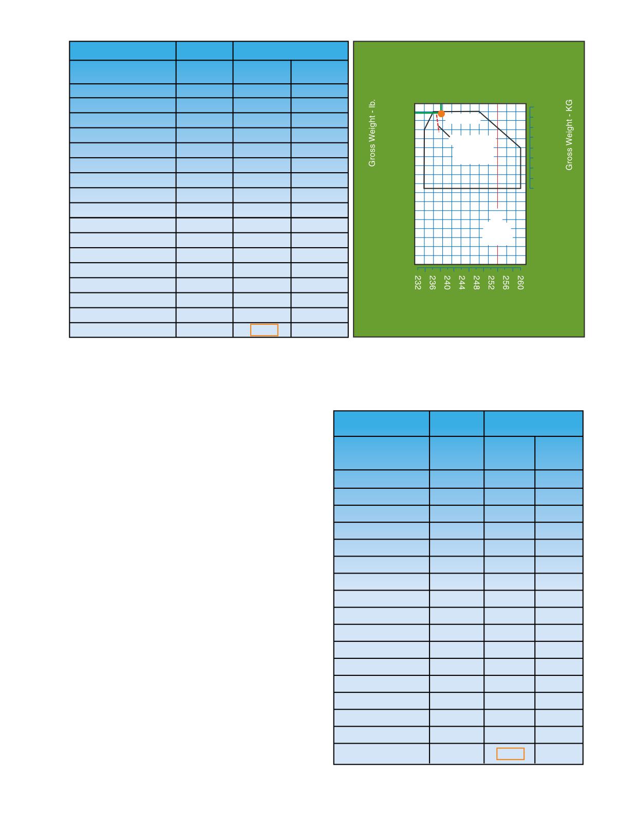
Longitudinal
Longitudinal
Weight
Arm
Moment
Fuselage Station (in. from Datum)
(pounds)
(inches)
(lb/inches)
Basic Empty Weight
1,400
107.75
150,850
91
93
95
97
99 101 103
170
49.5
8,415
2,500
Pilot
1,100
(Point A)
1,050
Fwd Passenger
250
49.5
12,375
2,300
1,000
Right Fwd Baggage
44
0
2,100
950
Most Fwd
Left Fwd Baggage
44
0
CG with
900
1,900
850
Full Fuel
Right Aft Passenger
79.5
0
800
1,700
Left Aft Passenger
185
79.5
14,708
750
700
1,500
Right Aft Baggage
50
79.5
3,975
Left Aft Baggage
50
79.5
3,975
C
L
Main
Totals with Zero Fuel
2,105
194,298
Rotor
Main Fuel Tank
184
106
19,504
Aux Fuel Tank
110
102
11,220
Fuselage Station (CM from Datum)
Totals with Fuel
2,399
225,022
CG
93.8
Figure 7-9. Use the longitudinal CG envelope along with the computed CGs to determine if the helicopter is loaded properly.
inches, the CG is 93.8. Plotting this CG against the
Lateral
weight indicates that the helicopter is loaded within
the longitudinal limits (point A).
Weight
Arm
Moment
(pounds)
(inches)
(lb/inches)
CALCULATING LATERAL CG
Some helicopter manufacturers require that you also
Basic Empty Weight
1,400
0
0
determine the lateral CG limits. These calculations are
Pilot
170
12.2
2,074
similar to longitudinal calculations. However, since the
Fwd Passenger
250
-10.4
-2,600
lateral CG datum line is almost always defined as the
center of the helicopter, you are likely to encounter
Right Fwd Baggage
11.5
0
negative CGs and moments in your calculations.
Left Fwd Baggage
-11.5
0
Negative values are located on the left side while posi-
Right Aft Passenger
12.2
0
tive stations are located on the right.
Left Aft Passenger
185
-12.2
-2,257
Refer to figure 7-10. When computing moment for the
Right Aft Baggage
50
12.2
610
pilot, 170 pounds is multiplied by the arm of 12.2 inches
Left Aft Baggage
50
-12.2
-610
resulting in a moment of 2,074 pound-inches. As with
any weight placed right of the aircraft centerline, the
moment is expressed as a positive value. The forward
Totals with Zero Fuel
2,105
-2,783
passenger sits left of the aircraft centerline. To compute
this moment, multiply 250 pounds by -10.4 inches. The
result is in a moment of -2,600 pound-inches. Once the
Main Fuel Tank
184
-13.5
-2,484
aircraft is completely loaded, the weights and moments
Aux Fuel Tank
110
13
1,430
are totaled and the CG is computed. Since more weight
is located left of the aircraft centerline, the resulting
total moment is -3,837 pound-inches. To calculate CG,
Totals with Fuel
2,399
-3,837
divide -3,837 pound-inches by the total weight of 2,399
CG
-1.6
pounds. The result is -1.6 inches, or a CG that is 1.6
inches left of the aircraft centerline.
Figure 7-10. Computed Lateral CG.
7-7
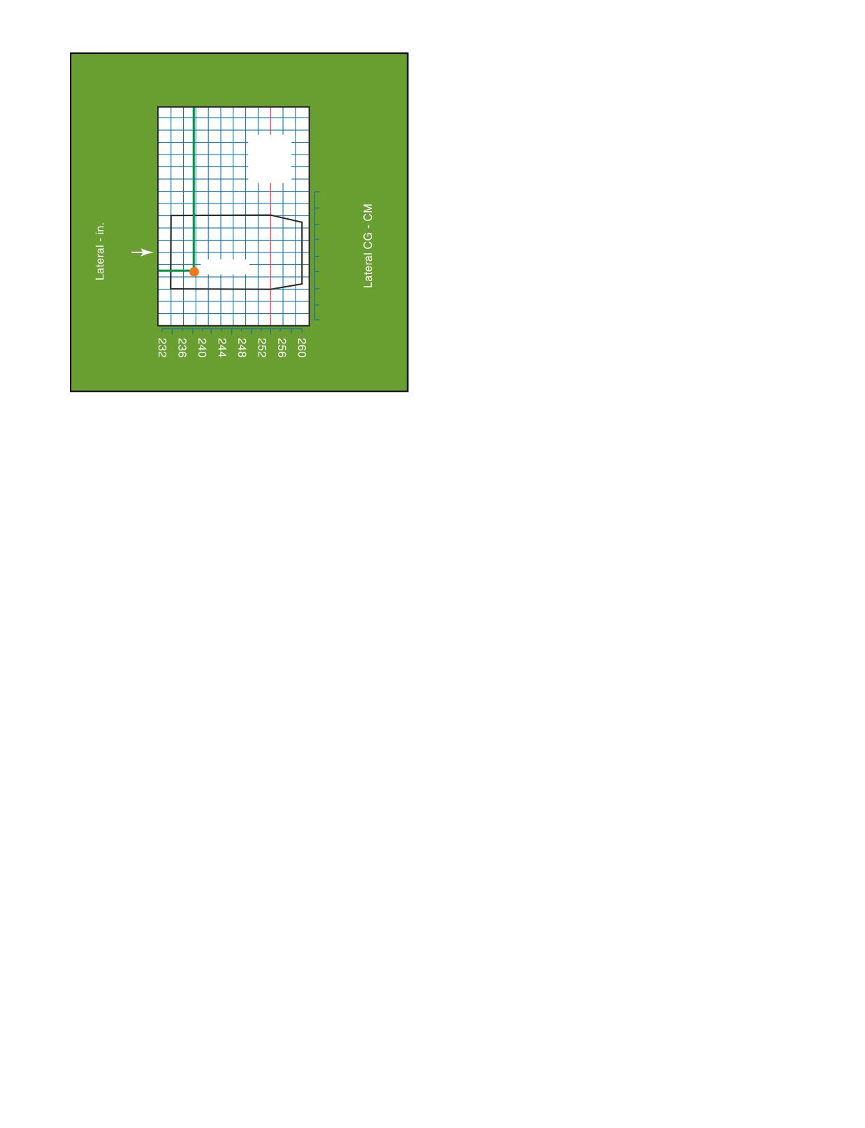
Lateral
Lateral CG is often plotted against the longitudinal CG.
Fuselage Station (in. from Datum)
[Figure 7-11] In this case, -1.6 is plotted against 93.8,
91
93
95
97
99 101 103
which was the longitudinal CG determined in the previ-
ous problem. The intersection of the two lines falls well
within the lateral CG envelope.
C
L
Main
Rotor
8R
6R
3R
4R
1R
2R
C
L
0
1L
(Point A)
2L
3L
4L
6L
8L
Fuselage Station (CM from Datum)
Figure 7-11. Use the lateral CG envelope to determine if the
helicopter is properly loaded.
7-8
Your ability to predict the performance of a helicopter
and pressure altitude must be clearly understood. True
is extremely important. It allows you to determine
altitude means the vertical height above mean sea level
how much weight the helicopter can carry before
and is displayed on the altimeter when the altimeter is
takeoff, if your helicopter can safely hover at a spe-
correctly adjusted to the local setting.
cific altitude and temperature, how far it will take to
climb above obstacles, and what your maximum
For example, if the local altimeter setting is 30.12 in.
climb rate will be.
Hg., and the altimeter is adjusted to this value, the
altimeter indicates exact height above sea level.
FACTORS AFFECTING PERFORMANCE
However, this does not reflect conditions found at this
A helicopter’s performance is dependent on the power
height under standard conditions. Since the altimeter
output of the engine and the lift production of the
setting is more than 29.92 in. Hg., the air in this exam-
rotors, whether it is the main rotor(s) or tail rotor. Any
ple has a higher pressure, and is more compressed,
factor that affects engine and rotor efficiency affects
indicative of the air found at a lower altitude.
performance. The three major factors that affect per-
Therefore, the pressure altitude is lower than the actual
formance are density altitude, weight, and wind.
height above mean sea level.
DENSITY ALTITUDE
To calculate pressure altitude without the use of an
The density of the air directly affects the performance
altimeter, remember that the pressure decreases
of the helicopter. As the density of the air increases,
approximately 1 inch of mercury for every 1,000-foot
engine power output, rotor efficiency, and aerodynamic
increase in altitude. For example, if the current local
lift all increase. Density altitude is the altitude above
altimeter setting at a 4,000-foot elevation is 30.42, the
mean sea level at which a given atmospheric density
pressure altitude would be 3,500 feet. (30.42 - 29.92 =
occurs in the standard atmosphere. It can also be
.50 in. Hg. 3 1,000 feet = 500 feet. Subtracting 500 feet
interpreted as pressure altitude corrected for nonstan-
from 4,000 equals 3,500 feet).
dard temperature differences.
The four factors that most affect density altitude are:
Pressure altitude is displayed as the height above a
atmospheric pressure, altitude, temperature, and the
standard datum plane, which, in this case, is a theoret-
moisture content of the air.
ical plane where air pressure is equal to 29.92 in. Hg.
Pressure altitude is the indicated height value on the
altimeter when the altimeter setting is adjusted to
ATMOSPHERIC PRESSURE
29.92 in. Hg. Pressure altitude, as opposed to true alti-
Due to changing weather conditions, atmospheric pres-
tude, is an important value for calculating perform-
sure at a given location changes from day to day. If the
ance as it more accurately represents the air content at
pressure is lower, the air is less dense. This means a
a particular level. The difference between true altitude
higher density altitude and less helicopter performance.
Density Altitude-Pressure altitude corrected for nonstandard temper-
Pressure Altitude-The height above the standard pressure level of
ature variations. Performance charts for many older aircraft are based
29.92 in. Hg. It is obtained by setting 29.92 in the barometric pressure
on this value.
window and reading the altimeter.
Standard Atmosphere-At sea level, the standard atmosphere consists
True Altitude-The actual height of an object above mean sea level.
of a barometric pressure of 29.92 inches of mercury (in. Hg.) or 1013.2
millibars, and a temperature of 15°C (59°F). Pressure and temperature
normally decrease as altitude increases. The standard lapse rate in the
lower atmosphere for each 1,000 feet of altitude is approximately 1 in.
Hg. and 2°C (3.5°F). For example, the standard pressure and tempera-
ture at 3,000 feet mean sea level (MSL) is 26.92 in. Hg. (29.92 - 3) and
9°C (15°C - 6°C).
8-1
ALTITUDE
One of the ways you can determine density altitude is
As altitude increases, the air becomes thinner or less
through the use of charts designed for that purpose.
dense. This is because the atmospheric pressure acting
[Figure 8-1]. For example, assume you are planning to
on a given volume of air is less, allowing the air mole-
depart an airport where the field elevation is 1,165 feet
cules to move further apart. Dense air contains more air
MSL, the altimeter setting is 30.10, and the tempera-
molecules spaced closely together, while thin air con-
ture is 70°F. What is the density altitude? First, correct
tains less air molecules because they are spaced further
for nonstandard pressure (30.10) by referring to the
apart. As altitude increases, density altitude increases.
right side of the chart, and subtracting 165 feet from
the field elevation. The result is a pressure altitude of
TEMPERATURE
1,000 feet. Then, enter the chart at the bottom, just
Temperature changes have a large affect on density alti-
above the temperature of 70°F (21°C). Proceed up the
tude. As warm air expands, the air molecules move fur-
chart vertically until you intercept the diagonal 1,000-
ther apart, creating less dense air. Since cool air
foot pressure altitude line, then move horizontally to
contracts, the air molecules move closer together, cre-
the left and read the density altitude of approximately
ating denser air. High temperatures cause even low ele-
2,000 feet. This means your helicopter will perform as
vations to have high density altitudes.
if it were at 2,000 feet MSL on a standard day.
Most performance charts do not require you to com-
MOISTURE (HUMIDITY)
pute density altitude. Instead, the computation is built
The water content of the air also changes air density
into the performance chart itself. All you have to do is
because water vapor weighs less than dry air.
enter the chart with the correct pressure altitude and the
Therefore, as the water content of the air increases, the
temperature.
air becomes less dense, increasing density altitude and
decreasing performance.
WEIGHT
Lift is the force that opposes weight. As weight
Humidity, also called “relative humidity,” refers to the
increases, the power required to produce the lift needed
amount of water vapor contained in the atmosphere,
to compensate for the added weight must also increase.
and is expressed as a percentage of the maximum
Most performance charts include weight as one of the
amount of water vapor the air can hold. This amount
variables. By reducing the weight of the helicopter, you
varies with temperature; warm air can hold more water
may find that you are able to safely take off or land at a
vapor, while colder air can hold less. Perfectly dry air
location that otherwise would be impossible. However,
that contains no water vapor has a relative humidity of
if you are ever in doubt about whether you can safely
0 percent, while saturated air that cannot hold any more
perform a takeoff or landing, you should delay your
water vapor, has a relative humidity of 100 percent.
takeoff until more favorable density altitude conditions
exist. If airborne, try to land at a location that has more
Humidity alone is usually not considered an important
favorable conditions, or one where you can make a
factor in calculating density altitude and helicopter per-
landing that does not require a hover.
formance; however, it does contribute. There are no
rules-of-thumb or charts used to compute the effects of
In addition, at higher gross weights, the increased
humidity on density altitude, so you need to take this
power required to hover produces more torque, which
into consideration by expecting a decrease in hovering
means more antitorque thrust is required. In some heli-
and takeoff performance in high humidity conditions.
copters, during high altitude operations, the maximum
antitorque produced by the tail rotor during a hover
HIGH AND LOW
may not be sufficient to overcome torque even if the
DENSITY ALTITUDE CONDITIONS
gross weight is within limits.
You need to thoroughly understand the terms “high
density altitude” and “low density altitude.” In general,
WINDS
high density altitude refers to thin air, while low den-
Wind direction and velocity also affect hovering, take-
sity altitude refers to dense air. Those conditions that
off, and climb performance. Translational lift occurs
result in a high density altitude (thin air) are high ele-
anytime there is relative airflow over the rotor disc.
vations, low atmospheric pressure, high temperatures,
This occurs whether the relative airflow is caused by
high humidity, or some combination thereof. Lower
helicopter movement or by the wind. As wind speed
elevations, high atmospheric pressure, low tempera-
increases, translational lift increases, resulting in less
tures, and low humidity are more indicative of low
power required to hover.
density altitude (dense air). However, high density
altitudes may be present at lower elevations on hot
The wind direction is also an important consideration.
days, so it is important to calculate the density altitude
Headwinds are the most desirable as they contribute to
and determine performance before a flight.
the most increase in performance. Strong crosswinds
8-2
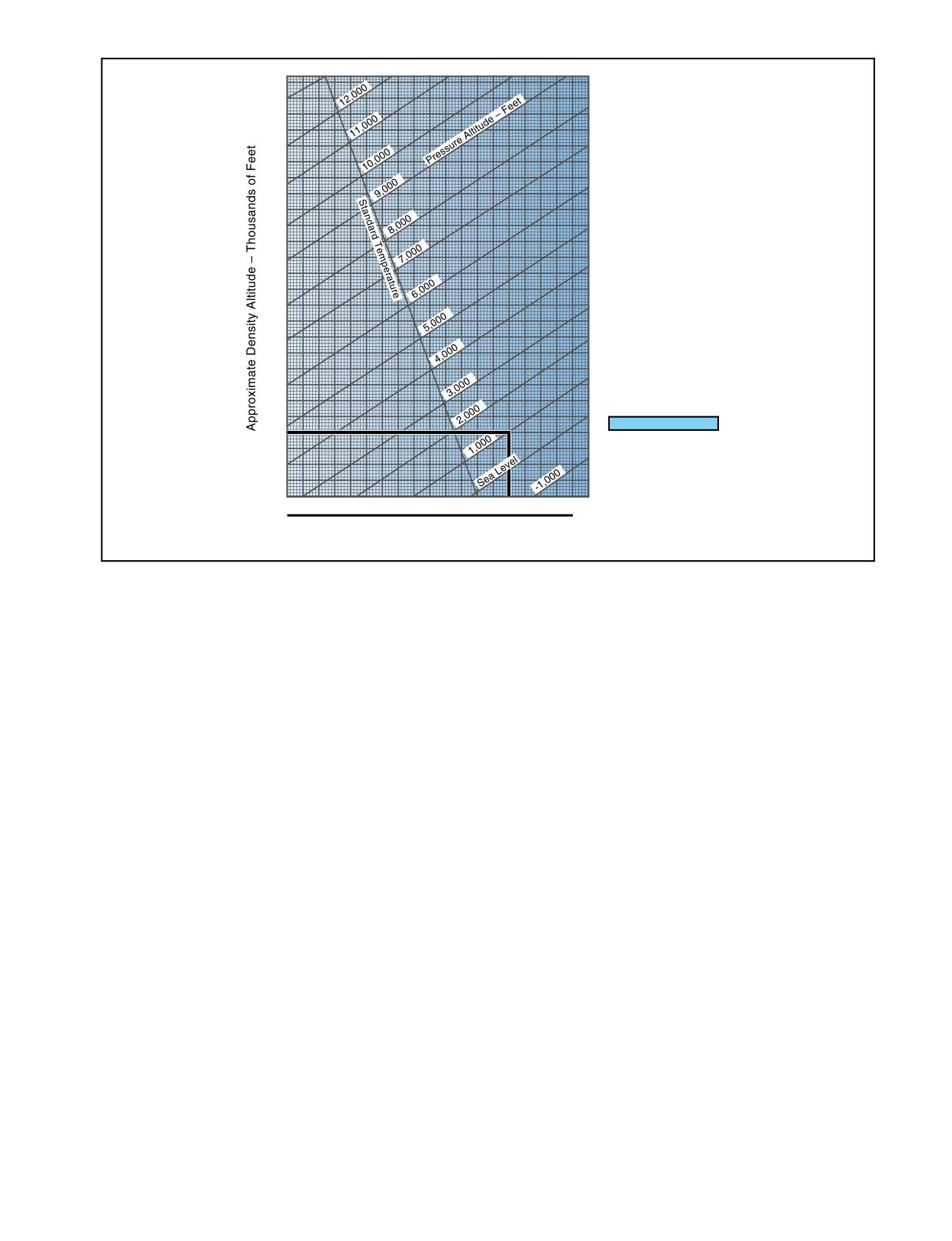
13
Altimeter
Pressure
Setting
Altitude
12
Conversion
Factor
11
28.0
1,824
28.1
1,727
10
28.2
1,630
28.3
1,533
28.4
1,436
9
28.5
1,340
28.6
1,244
8
28.7
1,148
28.8
1,053
28.9
957
7
29.0
863
29.1
768
6
29.2
673
29.3
579
29.4
485
5
29.5
392
29.6
298
29.7
205
4
29.8
112
29.9
20
3
29.92
0
30.0
-73
30.1
-165
2
30.2
-257
30.3
-348
1
30.4
-440
30.5
-531
30.6
-622
SL
30.7
-712
°C
-18
-12
-7
-1
4
10
16
21
27
32
30.8
-803
°F
0
10
20
30
40
50
60
70
80
90
30.9
-893
31.0
-983
Outside Air Temperature
Figure 8-1. Density Altitude Chart.
and tailwinds may require the use of more tail rotor
actual flight tests. However, they do not test the hel-
thrust to maintain directional control. This increased
icopter under each and every condition shown on a
tail rotor thrust absorbs power from the engine, which
performance chart. Instead, they evaluate specific
means there is less power available to the main rotor
data and mathematically derive the remaining data.
for the production of lift. Some helicopters even have a
critical wind azimuth or maximum safe relative wind
HOVERING PERFORMANCE
chart. Operating the helicopter beyond these limits
Helicopter performance revolves around whether or
could cause loss of tail rotor effectiveness.
not the helicopter can be hovered. More power is
required during the hover than in any other flight
Takeoff and climb performance is greatly affected by
regime. Obstructions aside, if a hover can be maintained,
wind. When taking off into a headwind, effective trans-
a takeoff can be made, especially with the additional
lational lift is achieved earlier, resulting in more lift and
benefit of translational lift. Hover charts are provided for
a steeper climb angle. When taking off with a tailwind,
in ground effect (IGE) hover and out of ground effect
more distance is required to accelerate through transla-
(OGE) hover under various conditions of gross weight,
tion lift.
altitude, temperature, and power. The “in ground effect”
hover ceiling is usually higher than the “out of ground
PERFORMANCE CHARTS
effect” hover ceiling because of the added lift benefit
In developing performance charts, aircraft manufactur-
produced by ground effect.
ers make certain assumptions about the condition of the
helicopter and the ability of the pilot. It is assumed that
the helicopter is in good operating condition and the
In Ground Effect (IGE) Hover-Hovering close to the surface (usually
engine is developing its rated power. The pilot is
less than one rotor diameter above the surface) under the influence of
ground effect.
assumed to be following normal operating procedures
and to have average flying abilities. Average means a
pilot capable of doing each of the required tasks cor-
Out of Ground Effect (OGE) Hover-Hovering greater than one rotor
rectly and at the appropriate times.
diameter distance above the surface. Because induced drag is greater
while hovering out of ground effect, it takes more power to achieve a
hover. See Chapter 3-Aerodynamics of Flight for more details on IGE
Using these assumptions, the manufacturer devel-
and OGE hover.
ops performance data for the helicopter based on
8-3
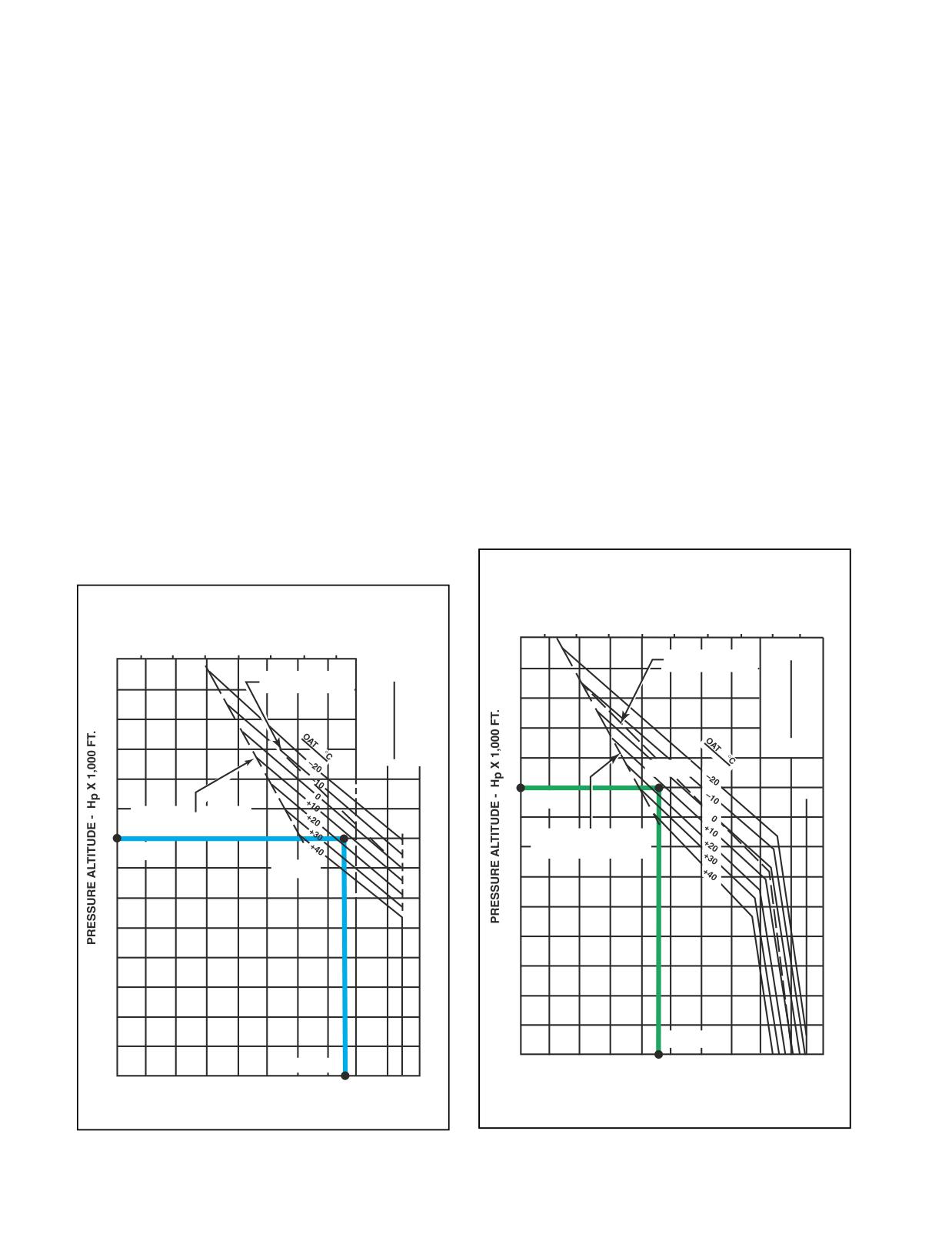
As density altitude increases, more power is required to
Since the gross weight of your helicopter is less than
hover. At some point, the power required is equal to the
this, you can safely hover with these conditions.
power available. This establishes the hovering ceiling
under the existing conditions. Any adjustment to the
SAMPLE PROBLEM 2
gross weight by varying fuel, payload, or both, affects
Once you reach the remote location in the previous
the hovering ceiling. The heavier the gross weight, the
problem, you will need to hover out of ground effect
lower the hovering ceiling. As gross weight is
for some of the pictures. The pressure altitude at the
decreased, the hover ceiling increases.
remote site is 9,000 feet, and you will use 50 pounds
of fuel getting there. (The new gross weight is now
SAMPLE PROBLEM 1
1,200 pounds.) The temperature will remain at +15°C.
You are to fly a photographer to a remote location to
Using figure 8-3, can you accomplish the mission?
take pictures of the local wildlife. Using figure 8-2, can
you safely hover in ground effect at your departure
Enter the chart at 9,000 feet (point A) and proceed to
point with the following conditions?
point B (+15°C). From there determine that the maxi-
mum gross weight to hover out of ground effect is
Pressure Altitude
8,000 feet
approximately 1,130 pounds (point C). Since your
Temperature
+15°C
gross weight is higher than this value, you will not be
Takeoff Gross Weight
1,250 pounds
able to hover with these conditions. To accomplish the
R.P.M
104%
mission, you will have to remove approximately 70
pounds before you begin the flight.
First enter the chart at 8,000 feet pressure altitude
(point A), then move right until reaching a point mid-
way between the +10°C and +20°C lines (point B).
These two sample problems emphasize the importance of
From that point, proceed down to find the maximum
determining the gross weight and hover ceiling throughout
gross weight where a 2 foot hover can be achieved. In
this case, it is approximately 1,280 pounds (point C).
OUT OF GROUND EFFECT
FULL THROTTLE ( OR LIMIT MANIFOLD
PRESSURE) AND 104% RPM
IN GROUND EFFECT AT 2 FOOT SKID CLEARANCE
GROSS WEIGHT - KGS.
FULL THROTTLE AND 104% RPM
425
450
475
500
525
550
575
600
625
GROSS WEIGHT - KGS.
14
OAT
425
450
475
500
525
550
575
14
STANDARD DAY
OAT
13
°C °F
- 20
-
4
13
STANDARD DAY
°C °F
- 10
+
14
– 20
-
4
12
0
+
32
– 10
+
14
+ 10
+
50
12
0
+
32
+ 20
+
68
+ 10
+
50
11
+ 30
+
86
+ 20
+
68
+ 40
+ 104
11
+ 30
+
86
+ 40
+ 104
10
(Point B)
10
9
(Point A)
9
DENSITY ALTITUDE
8
12,600 FT
1,370
8
DENSITY ALTITUDE
7
(Point A)
12,600 FT
7
(Point B)
6
6
5
5
4
4
3
3
2
2
1
(Point C)
1
(Point C)
0900
1,000
1,100
1,200
1,300
1,400
0
GROSS WEIGHT - LBS.
900
1,000
1,100
1,200
1,300
1,400
MAX CONT. OR FULL THROTTLE
GROSS WEIGHT - LBS.
OGE HOVER CEILING VS. GROSS WEIGHT
IGE HOVER CEILING VS. GROSS WEIGHT
Figure 8-2. In Ground Effect Hover Ceiling versus Gross
Figure 8-3. Out of Ground Effect Hover Ceiling versus Gross
Weight Chart.
Weight Chart.
8-4
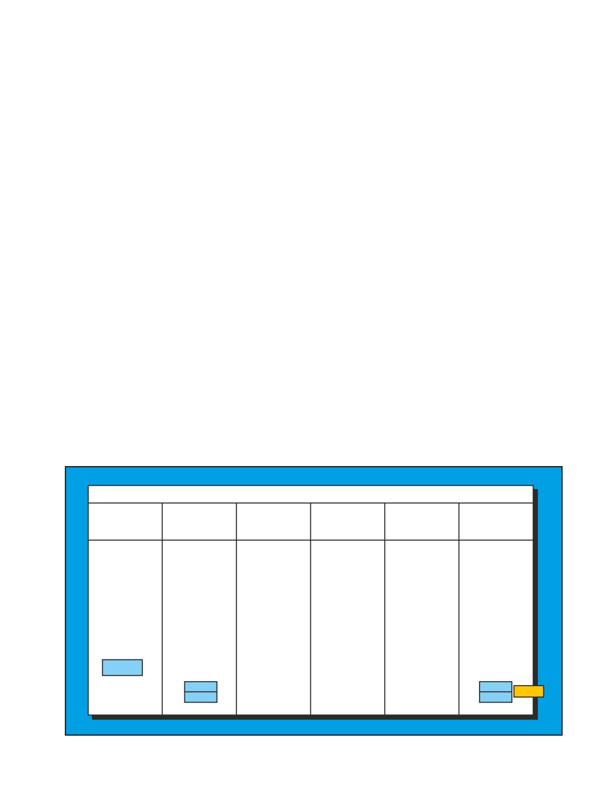
the entire flight operation. Being able to hover at the take-
headed by 95°F. The values are 1,102 feet and 1,538
off location with a certain gross weight does not ensure the
feet. Since 5,000 is halfway between 4,000 and 6,000,
same performance at the landing point. If the destination
the interpolated value should be halfway between these
point is at a higher density altitude because of higher ele-
two values or 1,320 feet ([1,102 + 1,538] 4 2 = 1,320).
vation, temperature, and/or relative humidity, more power
is required to hover. You should be able to predict whether
CLIMB PERFORMANCE
hovering power will be available at the destination by
Most of the factors affecting hover and takeoff per-
knowing the temperature and wind conditions, using the
formance also affect climb performance. In addition,
performance charts in the helicopter flight manual, and
turbulent air, pilot techniques, and overall condition of
making certain power checks during hover and in flight
the helicopter can cause climb performance to vary.
prior to commencing the approach and landing.
A helicopter flown at the “best rate-of-climb” speed
TAKEOFF PERFORMANCE
will obtain the greatest gain in altitude over a given
If takeoff charts are included in the rotorcraft flight man-
period of time. This speed is normally used during the
ual, they usually indicate the distance it takes to clear a 50-
climb after all obstacles have been cleared and is usu-
foot obstacle based on various conditions of weight,
ally maintained until reaching cruise altitude. Rate of
pressure altitude, and temperature. In addition, the values
climb must not be confused with angle of climb.
computed in the takeoff charts usually assume that the
Angle of climb is a function of altitude gained over a
flight profile is per the applicable height-velocity diagram.
given distance. The best rate-of-climb speed results in
the highest climb rate, but not the steepest climb angle
and may not be sufficient to clear obstructions. The
SAMPLE PROBLEM 3
“best angle-of-climb” speed depends upon the power
In this example, determine the distance to clear a 50-
available. If there is a surplus of power available, the
foot obstacle with the following conditions:
helicopter can climb vertically, so the best angle-of-
Pressure Altitude
5,000 feet
climb speed is zero.
Takeoff Gross Weight
2,850 pounds
Temperature
95°F
Wind direction and speed have an effect on climb per-
formance, but it is often misunderstood. Airspeed is
Using figure 8-4, locate 2,850 pounds in the first col-
the speed at which the helicopter is moving through
umn. Since the pressure altitude of 5,000 feet is not one
the atmosphere and is unaffected by wind.
of the choices in column two, you have to interpolate
Atmospheric wind affects only the groundspeed, or
between the values from the 4,000- and 6,000-foot
speed at which the helicopter is moving over the
lines. Follow each of these rows out to the column
earth’s surface. Thus, the only climb performance
TAKE-OFF DISTANCE (FEET TO CLEAR 50 FOOT OBSTACLE)
Pressure
At
At
Gross
At
At
Altitude
-13°F
23°F
Weight
59°F
95°F
Feet
-25°C
-5°C
Pounds
15°C
35°C
2,150
SL
373
401
430
458
2,000
400
434
461
491
4,000
428
462
494
527
6,000
461
510
585
677
8,000
567
674
779
896
2,500
SL
531
569
613
652
2,000
568
614
660
701
4,000
611
660
709
759
6,000
654
727
848
986
8,000
811
975
1,144
1,355
2,850
SL
743
806
864
929
2,000
770
876
929
1,011
4,000
861
940
1,017
1,102
1,320
6,000
939
1,064
1,255
1,538
8,000
1,201
1,527
-
-
Figure 8-4. Takeoff Distance Chart.
8-5
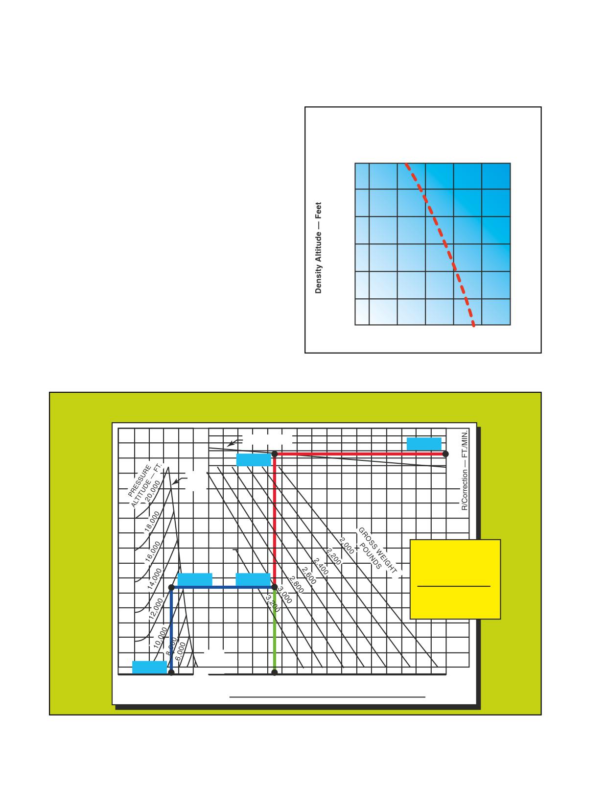
affected by atmospheric wind is the angle of climb and
Other rate-of-climb charts use density altitude as a
not the rate of climb.
starting point. [Figure 8-6] While it cleans up the chart
somewhat, you must first determine density altitude.
SAMPLE PROBLEM 4
Notice also that this chart requires a change in the indi-
Determine the best rate of climb using figure 8-5. Use
cated airspeed with a change in altitude.
the following conditions:
RATE OF CLIMB/DENSITY ALTITUDE
Pressure Altitude
12,000 feet
2,350 LBS. GROSS WEIGHT
Outside Air Temperature
+10°C
BEST RATE OF CLIMB SPEED VARIES WITH
Gross Weight
3,000 pounds
ALTITUDE; 57 MPH AT S.L. DECREASING TO 49
Power
Takeoff Power
MPH, IAS AT 12,000 FT.
12,000
Anti-ice
ON
Indicated Airspeed
52 knots
10,000
With this chart, first locate the temperature of +10°C
(point A). Then proceed up the chart to the 12,000-foot
8,000
pressure altitude line (point B). From there, move hori-
zontally to the right until you intersect the 3,000-foot
6,000
line (point C). With this performance chart, you must
now determine the rate of climb with anti-ice off and
4,000
then subtract the rate of climb change with it on. From
point C, go to the bottom of the chart and find that the
2,000
maximum rate of climb with anti-ice off is approxi-
mately 890 feet per minute. Then, go back to point C
and up to the anti-ice-on line (point D). Proceed hori-
0
400
600
800
1,000
1,200
1,400
zontally to the right and read approximately 240 feet
Rate of Climb, Feet Per Minute
per minute change (point E). Now subtract 240 from
890 to get a maximum rate of climb, with anti-ice on,
Figure 8-6. This chart uses density altitude in determining
maximum rate of climb.
of 650 feet per minute.
This Chart is Based on:
RATE OF CLIMB - MAXIMUM
Indicated Airspeed 60 MPH 52 KNOTS
TAKEOFF POWER
N2 ENGINE RPM 100%
0
ANTI-ICE ON
(Point E)
100
200
(Point D)
300
400
500
HOT
DAY
890 ft/min.
(Point B)
(Point C)
- 240 ft/min.
650 ft/min.
4,000
2,000
(Point A)
S.L.
-40 -20
0
20
40
0
2
4
6
8
10 12 14
16
18
20 22
24 26
28 30
32
OAT - ° C
ANTI-ICE OFF RATE OF CLIMB - FT./MIN. (X 100)
Figure 8-5. Maximum Rate-of-Climb Chart.
8-6
From the previous chapters, it should be apparent that
your responsibility to ensure the aircraft is in an air-
no two helicopters perform the same way. Even when
worthy condition.
flying the same model of helicopter, wind, temperature,
humidity, weight, and equipment make it difficult to
In preparation for flight, the use of a checklist is important
predict just how the helicopter will perform. Therefore,
so that no item is overlooked. Follow the manufacturer’s
this chapter presents the basic flight maneuvers in a
suggested outline for both the inside and outside inspec-
way that would apply to a majority of the helicopters.
tion. This ensures that all the items the manufacturer
In most cases, the techniques described apply to small
feels are important are checked. Obviously, if there are
training helicopters with:
other items you feel might need attention, inspect
them as well.
•
A single, main rotor rotating in a counterclock-
wise direction (looking downward on the rotor).
MINIMUM EQUIPMENT LISTS (MELS) AND
OPERATIONS WITH INOPERATIVE
•
An antitorque system.
EQUIPMENT
The Code of Federal Regulations (CFRs) requires that
Where a technique differs, it will be noted. For example,
all aircraft instruments and installed equipment be
a power increase on a helicopter with a clockwise rotor
operative prior to each departure. However, when the
system requires right antitorque pedal pressure instead
FAA adopted the minimum equipment list (MEL)
of left pedal pressure. In many cases, the terminology
concept for 14 CFR part 91 operations, flights were
“apply proper pedal pressure” is used to indicate both
allowed with inoperative items, as long as the inopera-
types of rotor systems. However, when discussing throt-
tive items were determined to be nonessential for safe
tle coordination to maintain proper r.p.m., there will be
flight. At the same time, it allowed part 91 operators,
no differentiation between those helicopters with a gov-
without an MEL, to defer repairs on nonessential
ernor and those without. In a sense, the governor is doing
equipment within the guidelines of part 91.
the work for you. In addition, instead of using the terms
collective pitch control and the cyclic pitch control
There are two primary methods of deferring maintenance
throughout the chapter, these controls are referred to as
on rotorcraft operating under part 91. They are the defer-
just collective and cyclic.
ral provision of 14 CFR part 91, section 91.213(d) and an
FAA-approved MEL.
Because helicopter performance varies with different
weather conditions and aircraft loading, specific nose
The deferral provision of section 91.213(d) is widely
attitudes and power settings will not be discussed. In
used by most pilot/operators. Its popularity is due to
addition, this chapter does not detail each and every
simplicity and minimal paperwork. When inoperative
attitude of a helicopter in the various flight maneuvers,
equipment is found during preflight or prior to depar-
nor each and every move you must make in order to
ture, the decision should be to cancel the flight, obtain
perform a given maneuver.
maintenance prior to flight, or to defer the item or
equipment.
When a maneuver is presented, there will be a brief
description, followed by the technique to accomplish
Maintenance deferrals are not used for in-flight discrep-
the maneuver. In most cases, there is a list of common
ancies. The manufacturer's RFM/POH procedures are
errors at the end of the discussion.
to be used in those situations. The discussion that
PREFLIGHT
Before any flight, you must ensure the helicopter is
airworthy by inspecting it according to the rotorcraft
flight manual, pilot’s operating handbook, or other
Minimum Equipment List (MEL)-An inventory of instruments and
information supplied either by the operator or the man-
equipment that may legally be inoperative, with the specific conditions
ufacturer. Remember that as pilot in command, it is
under which an aircraft may be flown with such items inoperative.
9-1
follows assumes that the pilot wishes to defer mainte-
With an approved MEL, if the position lights were dis-
nance that would ordinarily be required prior to flight.
covered inoperative prior to a daytime flight, the pilot
would make an entry in the maintenance record or dis-
Using the deferral provision of section 91.213(d), the
crepancy record provided for that purpose. The item is
pilot determines whether the inoperative equipment is
then either repaired or deferred in accordance with the
required by type design, the CFRs, or ADs. If the inop-
MEL. Upon confirming that daytime flight with inopera-
erative item is not required, and the helicopter can be
tive position lights is acceptable in accordance with the
safely operated without it, the deferral may be made.
provisions of the MEL, the pilot would leave the position
The inoperative item shall be deactivated or removed and
lights switch OFF, open the circuit breaker (or whatever
an INOPERATIVE placard placed near the appropriate
action is called for in the procedures document), and plac-
switch, control, or indicator. If deactivation or removal
ard the position light switch as INOPERATIVE.
involves maintenance (removal always will), it must be
accomplished by certificated maintenance personnel.
There are exceptions to the use of the MEL for deferral.
For example, should a component fail that is not listed
For example, if the position lights (installed equipment)
in the MEL as deferrable (the rotor tachometer, engine
were discovered to be inoperative prior to a daytime
tachometer, or cyclic trim, for example), then repairs
flight, the pilot would follow the requirements of sec-
are required to be performed prior to departure. If main-
tion 91.213(d).
tenance or parts are not readily available at that
location, a special flight permit can be obtained from
The deactivation may be a process as simple as the pilot
the nearest FSDO. This permit allows the helicopter to
positioning a circuit breaker to the OFF position, or as
be flown to another location for maintenance. This
complex as rendering instruments or equipment totally
allows an aircraft that may not currently meet applica-
inoperable. Complex maintenance tasks require a cer-
ble airworthiness requirements, but is capable of safe
tificated and appropriately rated maintenance person to
flight, to be operated under the restrictive special terms
perform the deactivation. In all cases, the item or equip-
and conditions attached to the special flight permit.
ment must be placarded INOPERATIVE.
All rotorcraft operated under part 91 are eligible to use
Deferral of maintenance is not to be taken lightly, and
the maintenance deferral provisions of section 91.213(d).
due consideration should be given to the effect an inop-
However, once an operator requests an MEL, and a Letter
erative component may have on the operation of a
of Authorization (LOA) is issued by the FAA, then the
helicopter, particularly if other items are inoperative.
use of the MEL becomes mandatory for that helicopter.
Further information regarding MELs and operations
All maintenance deferrals must be accomplished in
with inoperative equipment can be found in AC 91-67,
accordance with the terms and conditions of the MEL and
Minimum Equipment Requirements for General
the operator-generated procedures document.
Aviation Operations Under FAR Part 91.
The use of an MEL for rotorcraft operated under part 91
ENGINE START
also allows for the deferral of inoperative items or
AND ROTOR ENGAGEMENT
equipment. The primary guidance becomes the FAA-
During the engine start, rotor engagement, and systems
approved MEL issued to that specific operator and
ground check, use the manufacturer’s checklists. If a
N-numbered helicopter.
problem arises, have it checked before continuing.
Prior to performing these tasks, however, make sure
The FAA has developed master minimum equipment
the area near the helicopter is clear of personnel and
lists (MMELs) for rotorcraft in current use. Upon writ-
equipment. Helicopters are safe and efficient flying
ten request by a rotorcraft operator, the local FAA Flight
machines as long as they are operated within the
Standards District Office (FSDO) may issue the appro-
parameters established by the manufacturer.
priate make and model MMEL, along with an LOA, and
the preamble. The operator then develops operations
ROTOR SAFETY CONSIDERATIONS
and maintenance (O&M) procedures from the MMEL.
The exposed nature of the main and tail rotors deserve
This MMEL with O&M procedures now becomes the
special caution. You must exercise extreme care when
operator's MEL. The MEL, LOA, preamble, and proce-
taxiing near hangars or obstructions since the distance
dures document developed by the operator must be on
between the rotor blade tips and obstructions is very
board the helicopter when it is operated.
difficult to judge. [Figure 9-1] In addition, you cannot
The FAA considers an approved MEL to be a supple-
see the tail rotor of some helicopters from the cabin.
mental type certificate (STC) issued to an aircraft by
Therefore, when hovering backwards or turning in
serial number and registration number. It therefore
those helicopters, allow plenty of room for tail rotor
becomes the authority to operate that aircraft in a condi-
clearance. It is a good practice to glance over your
tion other than originally type certificated.
shoulder to maintain this clearance.
9-2
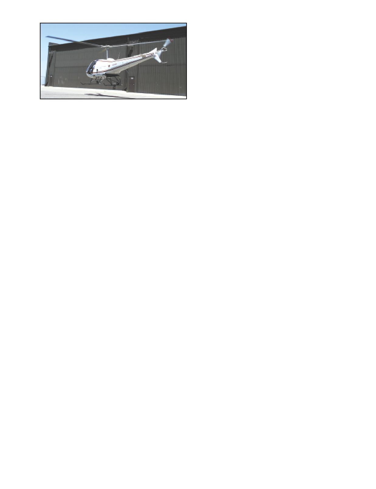
2.
brief passengers on the best way to approach and
board a helicopter with its rotors turning.
AIRCRAFT SERVICING-The helicopter rotor blades
should be stopped, and both the aircraft and the refuel-
ing unit properly grounded prior to any refueling oper-
ation. You, as the pilot, should ensure that the proper
grade of fuel and the proper additives, when required,
are being dispensed.
Figure 9-1. Exercise extreme caution when hovering near
Refueling the aircraft, while the blades are turning,
buildings or other aircraft.
known as "hot refueling," may be practical for certain
types of operation. However, this can be hazardous if
not properly conducted. Pilots should remain at the
Another rotor safety consideration is the thrust a heli-
flight controls; and refueling personnel should be
copter generates. The main rotor system is capable of
knowledgeable about the proper refueling procedures
blowing sand, dust, snow, ice, and water at high veloci-
and properly briefed for specific helicopter makes and
ties for a significant distance causing injury to nearby
models.
people and damage to buildings, automobiles, and other
aircraft. Loose snow, can severely reduce visibility and
Refueling units should be positioned to ensure ade-
obscure outside visual references. Any airborne debris
quate rotor blade clearance. Persons not involved with
near the helicopter can be ingested into the engine air
the refueling operation should keep clear of the area.
intake or struck by the main and tail rotor blades.
Smoking must be prohibited in and around the aircraft
SAFETY IN AND AROUND HELICOPTERS
during all refueling operations.
People have been injured, some fatally, in helicopter
accidents that would not have occurred had they been
EXTERNAL-LOAD RIGGERS-Rigger training is
informed of the proper method of boarding or deplan-
possibly one of the most difficult and continually
ing. A properly briefed passenger should never be
changing problems of the helicopter external-load
endangered by a spinning rotor. The simplest method
operator. A poorly rigged cargo net, light standard, or
of avoiding accidents of this sort is to stop the rotors
load pallet could result in a serious and costly accident.
before passengers are boarded or allowed to depart.
It is imperative that all riggers be thoroughly trained to
Because this action is not always practicable, and to
meet the needs of each individual external-load opera-
realize the vast and unique capabilities of the helicop-
tion. Since rigging requirements may vary several
ter, it is often necessary to take on passengers or to
times in a single day, proper training is of the utmost
deplane them while the engine and rotors are turning.
importance to safe operations.
To avoid accidents, it is essential that all persons asso-
ciated with helicopter operations, including passengers,
PILOT AT THE FLIGHT CONTROLS-Many heli-
be made aware of all possible hazards and instructed as
copter operators have been lured into a "quick turn-
to how they can be avoided.
around" ground operation to avoid delays at airport
terminals and to minimize stop/start cycles of the
Persons directly involved with boarding or deplaning
engine. As part of this quick turnaround, the pilot might
passengers, aircraft servicing, rigging, or hooking up
leave the cockpit with the engine and rotors turning.
external loads, etc., should be instructed as to their
Such an operation can be extremely hazardous if a gust
duties. It would be difficult, if not impossible, to cover
of wind disturbs the rotor disc, or the collective flight
each and every type of operation related to helicopters.
control moves causing lift to be generated by the rotor
A few of the more obvious and common ones are cov-
system. Either occurrence may cause the helicopter to
ered below.
roll or pitch, resulting in a rotor blade striking the tail-
boom or the ground. Good operating procedures dictate
RAMP ATTENDANTS AND AIRCRAFT SERVIC-
that pilots remain at the flight controls whenever the
ING PERSONNEL-These personnel should be
engine is running and the rotors are turning.
instructed as to their specific duties, and the proper
method of fulfilling them. In addition, the ramp atten-
EXTERNAL-LOAD HOOKUP PERSONNEL-
dant should be taught to:
There are several areas in which these personnel
should be knowledgeable. First, they should know the
1.
keep passengers and unauthorized persons out of
lifting capability of the helicopters involved. Since
the helicopter landing and takeoff area.
some operators have helicopter models with almost
9-3
identical physical characteristics but different lifting
5.
hold firmly to hats and loose articles.
capabilities, this knowledge is essential. For example,
6.
never reach up or dart after a hat or other object
a hookup person may be working with a turbocharged
that might be blown off or away.
helicopter on a high altitude project when a non-tur-
bocharged helicopter, which looks exactly the same to
7.
protect eyes by shielding them with a hand or by
the ground crew, comes to pick up a load. If the
squinting.
hookup person attaches a load greater than the
non-turbocharged helicopter can handle, a potentially
8.
if suddenly blinded by dust or a blowing object,
dangerous situation could exist.
stop and crouch lower; or better yet, sit down and
wait for help.
Second, know the pilots. The safest plan is to stan-
dardize all pilots in the manner in which sling loads
9.
never grope or feel your way toward or away
are picked up and released. Without pilot standardiza-
from the helicopter.
tion, the operation could be hazardous. The operator
should standardize the pilots on operations while
Since few helicopters carry cabin attendants, you, as
personnel are beneath the helicopter.
the pilot, will have to conduct the pre-takeoff and pre-
landing briefings. The type of operation dictates what
Third, know the cargo. Many items carried via sling are
sort of briefing is necessary. All briefings should
very fragile, others can take a beating. The hookup per-
include the following:
son should always know when a hazardous article is
involved and the nature of the hazard, such as explo-
1.
The use and operation of seatbelts for takeoff, en
sives, radioactive materials, and toxic chemicals. In
route, and landing.
addition to knowing this, the hookup person should be
2.
For overwater flights, the location and use of
familiar with the types of protective gear or clothing
flotation gear and other survival equipment that
and the actions necessary to protect their own safety
might be on board. You should also include how
and that of the operation.
and when to abandon the helicopter should a
ditching be necessary.
Fourth, know appropriate hand signals. When direct
radio communications between ground and flight per-
3.
For flights over rough or isolated terrain, all
sonnel are not used, the specific meaning of hand
occupants should be told where maps and sur-
signals should be coordinated prior to operations.
vival gear are located.
Fifth, know emergency procedures. Ground and flight
4.
Passengers should be instructed as to what
personnel should fully agree to and understand the
actions and precautions to take in the event of an
actions to be taken by all participants in the event of
emergency, such as the body position for best
emergencies. This prior planning is essential to avoid
spinal protection against a high vertical impact
injuries to all concerned.
landing (erect with back firmly against the seat
back); and when and how to exit after landing.
PASSENGERS-All persons who board a helicopter
Ensure that passengers are aware of the location
while its rotors are turning should be instructed in the
of the fire extinguisher and survival equipment.
safest means of doing so. Naturally, if you are at the
controls, you may not be able to conduct a boarding
5.
Smoking should not be permitted within 50 feet
briefing. Therefore, the individual who arranged for the
of an aircraft on the ground. Smoking could be
passengers' flight or is assigned as the ramp attendant
permitted, at the discretion of the pilot, except
should accomplish this task. The exact procedures may
under the following conditions:
vary slightly from one helicopter model to another, but
•
during all ground operations.
in general the following should suffice.
•
during, takeoff or landing.
When boarding-
•
when carrying flammable or hazardous
1.
stay away from the rear of the helicopter.
materials.
2.
approach or leave the helicopter in a crouching
manner.
When passengers are approaching or leaving a helicop-
ter that is sitting on a slope with the rotors turning, they
3.
approach from the side or front, but never out of
should approach and depart downhill. This affords the
the pilot's line of vision.
greatest distance between the rotor blades and the
4.
carry tools horizontally, below waist level, never
ground. If this involves walking around the helicopter,
upright or over the shoulder.
they should always go around the front, never the rear.
9-4
3.
Overcontrolling the antitorque pedals, which not
VERTICAL TAKEOFF TO A HOVER
only changes the handling of the helicopter, but
A vertical takeoff, or takeoff to a hover, is a maneuver
also changes the r.p.m.
in which the helicopter is raised vertically from the sur-
face to the normal hovering altitude (2 to 5 feet) with a
4.
Reducing throttle rapidly in situations where
minimum of lateral or longitudinal movement.
proper r.p.m. has been exceeded. This usually
results in exaggerated heading changes and loss
TECHNIQUE
of lift, resulting in loss of altitude.
Prior to any takeoff or maneuver, you should ensure
that the area is clear of other traffic. Then, head the hel-
icopter into the wind, if possible. Place the cyclic in the
HOVERING
neutral position, with the collective in the full down
Hovering is a maneuver in which the helicopter is main-
position. Increase the throttle smoothly to obtain and
tained in a nearly motionless flight over a reference
maintain proper r.p.m., then raise the collective. Use
point at a constant altitude and on a constant heading.
smooth, continuous movement, coordinating the throt-
The maneuver requires a high degree of concentration
tle to maintain proper r.p.m. As you increase the collec-
and coordination.
tive, the helicopter becomes light on the skids, and
torque tends to cause the nose to swing or yaw to the
TECHNIQUE
right unless sufficient left antitorque pedal is used to
To maintain a hover over a point, you should look for
maintain the heading. (On helicopters with a clockwise
small changes in the helicopter’s attitude and altitude.
main rotor system, the yaw is to the left and right pedal
When you note these changes, make the necessary con-
must be applied.)
trol inputs before the helicopter starts to move from the
point. To detect small variations in altitude or position,
As the helicopter becomes light on the skids, make nec-
your main area of visual attention needs to be some
essary cyclic pitch control adjustments to maintain a
distance from the aircraft, using various points on the
level attitude. When airborne, use the antitorque pedals
helicopter or the tip-path plane as a reference. Looking
to maintain heading and the collective to ensure contin-
too close or looking down leads to overcontrolling.
uous vertical assent to the normal hovering altitude.
Obviously, in order to remain over a certain point, you
When hovering altitude is reached, use the throttle and
should know where the point is, but your attention
collective to control altitude, and the cyclic to maintain
should not be focused there.
a stationary hover. Use the antitorque pedals to main-
tain heading. When a stabilized hover is achieved,
check the engine instruments and note the power
As with a takeoff, you control altitude with the collec-
required to hover. You should also note the position of
tive and maintain a constant r.p.m. with the throttle.
the cyclic. Cyclic position varies with wind and the
Use the cyclic to maintain the helicopter’s position and
amount and distribution of the load.
the pedals to control heading. To maintain the
helicopter in a stabilized hover, make small, smooth,
Excessive movement of any flight control requires a
coordinated corrections. As the desired effect occurs,
change in the other flight controls. For example, if
remove the correction in order to stop the helicopter’s
while hovering, you drift to one side, you naturally
movement. For example, if the helicopter begins to
move the cyclic in the opposite direction. When you do
move rearward, you need to apply a small amount of
this, part of the vertical thrust is diverted, resulting in a
forward cyclic pressure. However, neutralize this pres-
loss of altitude. To maintain altitude, you must increase
sure just before the helicopter comes to a stop, or it will
the collective. This increases drag on the blades and
begin to move forward.
tends to slow them down. To counteract the drag and
maintain r.p.m., you need to increase the throttle.
After you gain experience, you will develop a certain
Increased throttle means increased torque, so you must
“feel” for the helicopter. You will feel and see small
add more pedal pressure to maintain the heading. This
deviations, so you can make the corrections before the
can easily lead to overcontrolling the helicopter.
helicopter actually moves. A certain relaxed looseness
However, as your level of proficiency increases, prob-
develops, and controlling the helicopter becomes sec-
lems associated with overcontrolling decrease.
ond nature, rather than a mechanical response.
COMMON ERRORS
COMMON ERRORS
1.
Failing to ascend vertically as the helicopter
1.
Tenseness and slow reactions to movements of
becomes airborne.
the helicopter.
2.
Pulling through on the collective after becoming
airborne, causing the helicopter to gain too much
2.
Failure to allow for lag in cyclic and collective
altitude.
pitch, which leads to overcontrolling.
9-5
//////////////////////////////////////////